treatment and surgery guide - cochlear
TRANSCRIPT
| 1
Treatment and Surgery Guide
FOR PROFESSIONALS
A BONE ANCHORED FACIAL PROSTHETIC SOLUTION

ContentsIntroduction 4
Preparations 6
Vistafix one-stage surgery 19
Vistafix two-stage surgery 27
Aftercare 34
Complications and troubleshooting 37
Making and fitting the prosthesis 41
Cleaning and sterilization guidelines 47
AcknowledgementsThe protocols detailed in this manual originate from the clinical work carried out by:Anders Tjellström, M.D., Ph.D, D.SC.hcDr. Joacim Stalfors, M.D., Ph.DKerstin Bergström, C.D.T., M.D.hc and colleagues.
Department of Otolaryngology, Sahlgrenska University Hospital, Gothenburg, Sweden.
This publication sets forth detailed recommended procedures for using Cochlear™ Vistafix® surgical components and instruments. It offers guidance needed for performing the procedure but, as with any technical guide, the surgeon must consider the particular needs of each patient and make appropriate adjustments when and as required. The techniques shown in this guide are provided for your consideration only, and do not constitute direct medical or anaplastological advice from Cochlear. This guide is not a substitute for actual medical education and hands-on training.
Cochlear accepts no responsibility for any adverse outcomes if used with products not recommended by Cochlear. Close cooperation in an interdisciplinary team is essential for a successful outcome. Hands-on surgical workshops are available from Cochlear. Contact your local Cochlear office for details.
Products in this manual are protected by the following patents: US 5 735 790, US 5 935 170, EP 0715839, EP 0715838, US 07074222, WO 02/09622, US 7409070, EB 01633284, US 27009853, WO 04105650 and corresponding patents in other countries and pending patent applications. All products can be subject to change without notice. No part of this publication may be replaced, stored in a retrieval system, or transmitted, in any form by any electronic or mechanical means photocopying, recording or otherwise, without the prior written permission of the publisher.
NOTE: • Imagesinthisguidearenottoscale. • Notallproductsareavailableinallmarkets.Productavailabilityissubjecttoregulatory approval in the respective markets.

| 54 |
IntroductionSince 1979, the Cochlear™ Vistafix® bone anchored facial prosthetic solution has proven successful for thousands of patients worldwide. The Cochlear Vistafix System* – which combines titanium implants, abutments, and retention components for prostheses – has yielded excellent results for patients with craniofacial defects due to congenital conditions, trauma or cancer surgery.1
The Vistafix System builds on the technology of the Brånemark system, providing a means of offering permanent and secure retention for facial prostheses. The long-term predictability and success of this treatment is based on the creation of an active bond between the implant and the surrounding bone tissue – a process known as osseointegration.
The use of a precise implantation technique and attention to detail in soft tissue management is of utmost importance for a successful outcome and for a reaction-free implant site. This material offers guidance for you to consider in performing the surgical procedure and fitting the prosthesis. In order to obtain optimal results, surgeons, prosthodontists, anaplastologists and technicians should work in close collaboration, which should continue during the follow-up period.
* The Vistafix 3 System consists of: Cochlear Vistafix VXI300 Implants (Vistafix 3 Implants) and Cochlear Vistafix VXA300 Abutments (Vistafix 3 Abutments).
The prior generation Vistafix System consists of: Cochlear Vistafix ST Fixtures (flangeless) and Standard abutments.
| 76 |
Preliminary examination and consultationA thorough examination of the defect tissue bed should be performed and etiology of the defect should be determined: congenital, trauma or tumor surgery. Make sure that the patient has realistic expectations of the Vistafix® treatment. If the patient wishes to pursue osseointegrated implants, the sequence of therapy and the possible morbidities should be carefully described. Sketches, photographs, models and computer-manipulated photos are useful in this respect.
Multidisciplinary collaboration between maxillofacial surgeons, plastic surgeons and anaplastologists/prosthetists is always essential if optimal results are to be achieved. Inviting the members of the multidisciplinary team to surgery and making templates for implant placement in surgery is recommended.
External ear
Congenital and trauma patients
To optimize aesthetic results, auricular remnants are often removed. It is, however, important that the patient makes this decision and is aware that this removal is irreversible.
Tumor patients
For patients undergoing auriculectomy, a pre-surgical impression could facilitate future prosthetic procedures. In addition, specific surgical issues such as position of the tragus, and lining the tissue bed with a hairless split-thickness skin graft etc., should be discussed.
For tumor surgery, Vistafix Implants may be placed at the time of surgery in order to shorten the rehabilitation time. The patient’s age and the psychosocial implications of rehabilitation also need to be considered during treatment planning.
Orbit and midface defectsThe nature of the orbital defect and the morphology of the residual bone elements of the orbital rim need careful evaluation prior to implant placement. In addition, the prospective contours of the future orbital prosthesis should be anticipated so as to avoid the placement of implants in locations and directions that may adversely affect the aesthetic contours, or make it more difficult for the patient to attach or remove the prosthesis.
It is important to note that anaplastologists/prosthetists need to be able to conceal hardware within the prosthetic. Care should be taken in consultation with the entire multidisciplinary team to ensure appropriate placement of implants in a way that will facilitate an optimal aesthetic outcome.
The same principles should guide clinicians regarding implant placement in patients with nasal defects — namely, the needs of stability, support and retention, while avoiding implant placement which could adversely affect the aesthetic contours of the nasal prosthesis.
Treatment planning
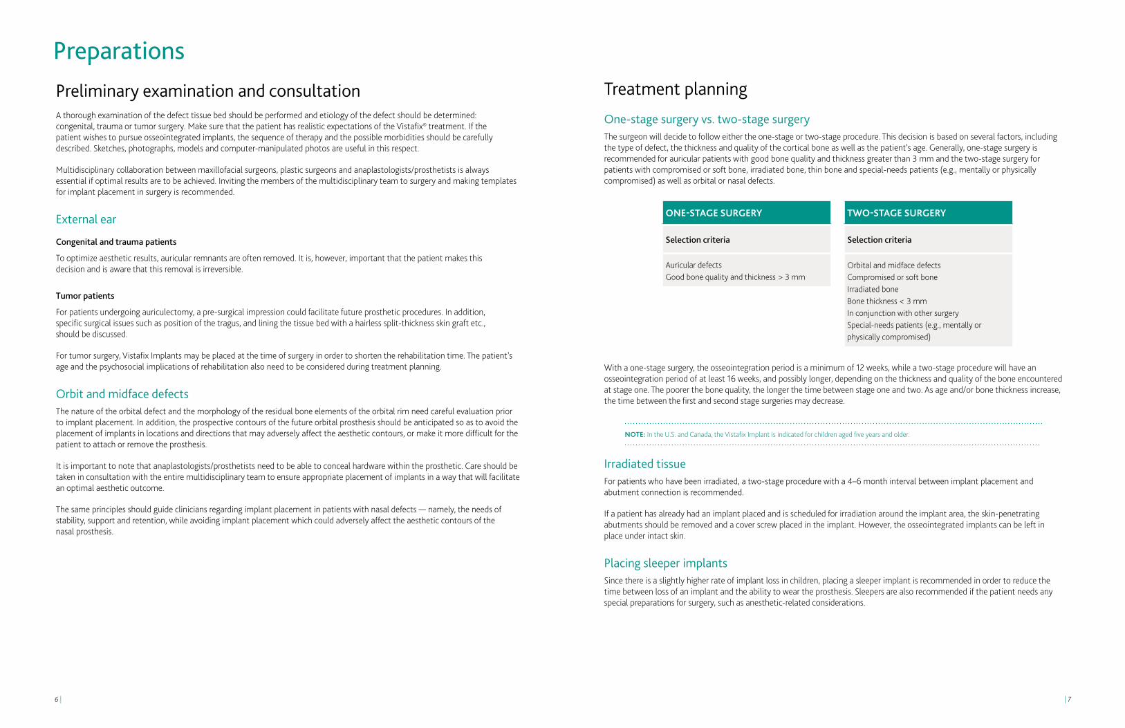
One-stage surgery vs. two-stage surgery The surgeon will decide to follow either the one-stage or two-stage procedure. This decision is based on several factors, including the type of defect, the thickness and quality of the cortical bone as well as the patient’s age. Generally, one-stage surgery is recommended for auricular patients with good bone quality and thickness greater than 3 mm and the two-stage surgery for patients with compromised or soft bone, irradiated bone, thin bone and special-needs patients (e.g., mentally or physically compromised) as well as orbital or nasal defects.
With a one-stage surgery, the osseointegration period is a minimum of 12 weeks, while a two-stage procedure will have an osseointegration period of at least 16 weeks, and possibly longer, depending on the thickness and quality of the bone encountered at stage one. The poorer the bone quality, the longer the time between stage one and two. As age and/or bone thickness increase, the time between the first and second stage surgeries may decrease.
NOTE: In the U.S. and Canada, the Vistafix Implant is indicated for children aged five years and older.
Irradiated tissueFor patients who have been irradiated, a two-stage procedure with a 4–6 month interval between implant placement and abutment connection is recommended.
If a patient has already had an implant placed and is scheduled for irradiation around the implant area, the skin-penetrating abutments should be removed and a cover screw placed in the implant. However, the osseointegrated implants can be left in place under intact skin.
Placing sleeper implantsSince there is a slightly higher rate of implant loss in children, placing a sleeper implant is recommended in order to reduce the time between loss of an implant and the ability to wear the prosthesis. Sleepers are also recommended if the patient needs any special preparations for surgery, such as anesthetic-related considerations.
Preparations
ONE-STAgE SURgERy
Selection criteria
Auricular defectsGood bone quality and thickness > 3 mm
TwO-STAgE SURgERy
Selection criteria
Orbital and midface defectsCompromised or soft boneIrradiated boneBone thickness < 3 mmIn conjunction with other surgery Special-needs patients (e.g., mentally or physically compromised)

| 98 |
Selecting the implant siteThe position of the implants should be selected in collaboration with the anaplastologist and/or prosthetic team for the best aesthetic and functional outcome. The implant sites should be carefully marked, using a thin needle or surgical ink, down to the bone while the patient is sitting and the face can still be easily seen. The location of specific anatomical landmarks such as the linea temporalis, suprameatal spine, foramen mastoideum etc., is often helpful. Anatomical variations due to congenital malformation and prior surgery should be considered.
Two implants are often sufficient for satisfactory retention. Three implants may be needed for optimal retention. An additional implant can also be placed as a sleeper implant in children or patients with irradiated bone.
Three implants are often used in conjunction with magnetic retention (Fig 1). When using a bar and clip retention, to obtain a good depth for the auricular prosthesis, the retention bar should be located under the anti-helix part of the prosthesis; therefore the implants should also be located directly under the anti-helix (Fig. 2).
The ideal position is approximately 20 mm from the center of the external ear canal opening or, in the case of the atretic ear, the anticipated opening. On the patient’s left side, the positions are at 4 o’clock and 1:30 (Fig. 3a). On the right side the corresponding positions are at 8 o’clock and 10:30 (Fig. 3b). When using three implants, placing the implants at 1:30, 3:00 and 4:30 (for left ear), and 10:30, 9:00 and 7:30 (for a right ear) is appropriate. The distance between the implants should be at least 10 mm to facilitate cleaning around the abutment.
Preparations for surgeryThe operating room should be prepared as for any other implant surgical procedure, where all instruments are available, functional and sterile.
Prepare the patient as for any surgical procedure, i.e., shave if needed and sterilize the incision area.
Local or general anesthesia can be used for adult patients. General anesthesia is most commonly used when children undergo Vistafix® surgery.
NOTE: • OnlysterileproductsdesignedfortheVXI300implantsystemshouldbeusedtogether. • Allsterileproductsareforsingleuseonly.Donotuseproductswithdamaged packaging or which are past their expiration date (Fig. 4). • Thepeel-openpackinsidethesterileproductboxactsasthesterilebarrier.Theplastic ampule is only a container for the sterile product (Fig. 5). Inside the plastic ampule, a titanium casing holds the product. The product should only be picked up by the relevant instrument. • Asetofallsterileproductsshouldalwaysbeavailable,asone-stagesurgerymay change to two-stage surgery. It is also recommended that for each component, an extra should be available in case it is dropped.
ONE-STAgE PROCEDURE
Implant installation and abutment connection
SURgICAL FOLLOw-UP TIME AFTER SURgERy
Change dressing and remove sutures, if healed
1 week
Remove final dressing 2-3 weeks
Osseointegration period Minimum of 12 weeks
Clean the implant area Daily by patient
Check by treatment team 3 weeks
MAKINg AND FITTINg THE PROSTHESIS
Make an impression of the defect area
12 weeks after surgery, given that the soft tissue is sufficiently healed
Fabricate the prosthesis 3-4 days
TwO-STAgE PROCEDURE
First stage: Implant installation
SURgICAL FOLLOw-UP TIME AFTER 1ST SURgERy
Remove sutures, if healed 1 week
Osseointegration period Minimum of 12 weeks
Second stage: Abutment connection
SURgICAL FOLLOw-UP TIME AFTER 2ND SURgERy
Change dressing and remove sutures, if healed
1 week
Remove final dressing and healing cap
2-3 weeks
Clean the implant area Daily by patient
Post-surgery check by treatment team
2-6 weeks depending on healing
MAKINg AND FITTINg THE PROSTHESIS
Make an impression of the defect area
2-6 weeks after surgery
Fabricate the prosthesis 3-4 days
Treatment schedule
NOTE: As technology develops, new ways of producing guides for surgery and planning for the prothesis may alter the timing for making and fitting the prosthesis.
5
4Measuring implant stabilityResonance frequency analysis (RFA) is an option that can supply clinically relevant information about the state of the implant-bone interface at any stage of the treatment or follow-up examinations. The measurement is performed with a small SmartPeg, which acts as a transducer attached to the implant or abutment.
For more information about the Osstell device and SmartPeg, please visit www.osstell.com. Studies indicate that implants with high and increasing implant stability quotient (ISQ) values are successfully integrated. At the same time, low and decreasing ISQ values may be a sign of ongoing implant failure and/or marginal bone loss.2
3a
3b
2
1
Bar and clip attachment
Magnet retention

| 1110 |
Component selection
Auricular prosthesesThe most common abutment lengths for auricular prostheses are 3.5 and 4.5 mm. A low profile on the anchoring system will often offer a more aesthetic prothesis, however, the ability to clean the abutment area is important. For patients with special anatomy or very thick skin around the abutments, longer abutments may be necessary. When a one-stage surgical procedure is planned, it is recommended to always have cover screws available during surgery in case bone quality is softer than anticipated and a two-stage procedure is required instead.
It is recommended that you always keep additional components for a 3 mm implant insertion available during surgery in case bone thickness is less than expected.
Orbital and midface prosthesesFor orbital and midface prostheses a two-stage procedure is recommended. The patient’s unique clinical needs determine the selection of implant and abutment used in surgery. The case should be carefully planned with anaplastologists and experienced clinicians. In general, it is recommended to use a 4 mm implant when bone volume allows and place sleeper implants with cover screws in irradiated or soft bone.
NOTE: • Avoidlongcantileverforces. • TheCochlear™ Vistafix® System is contraindicated for patients with insufficient bone quality and quantity to provide stability and support for the implant.
Stage 2
90940 Biopsy punch Ø4 mm
Typical set-up for Vistafix 3 one-stage surgery (4 mm)
92139 Guide drill 3+4 mm, Ø2.3 mm
93101 VXI300Implant 4 mm,
Ø4.5 mm
92141 Widening drill
with countersink 4 mm,
Ø4.1 mm
90802 Healing cap
Ø14 mm
92994 VXA300
Abutment 3.5 mm
92995 VXA300
Abutment 4.5 mm
92996 VXA300
Abutment 6 mm
90940 Biopsy punch
Ø4 mm
92997 VXA300
Abutment 7.5 mm
92998 VXA300Healingabutment
Typical set-up for Vistafix 3 two-stage surgery (4 mm)
90802 Healing cap
Ø14 mm
92994 VXA300
Abutment 3.5 mm
92995 VXA300
Abutment 4.5 mm
92996 VXA300
Abutment 6 mm
92997 VXA300
Abutment 7.5 mm
92998 VXA300Healingabutment
92139 Guide drill 3+4 mm, Ø2.3 mm
93102Cover screw conical
for Vistafix VXI300Implant
Stage 1
93100 VXI300Implant 4 mm,
Ø4.5 mm
92141 Widening drill
with countersink 4 mm,
Ø4.1 mm

| 1312 |
Bar or magnet retention
Bar construction A bar construction with clips is one option for retaining the prosthesis with a strong, secure connection. Ferro-magnetic components need to be removed prior to MRI scanning. For most auricular prostheses it is possible to choose a bar construction.
Magnetic attachment In cases where space is limited, where cleaning under the bar would be difficult, or where the patient has reduced motor skills, a magnetic attachment* can be an alternate retention solution. If magnets are used, a magnacap attached to an abutment is preferable, compared to a magnabutment mounted directly on the implant. This is because it is not possible to apply a counter torque when attaching the magnabutment to the implant. Magnabutments are a contraindication to MRI. After removal of the magnabutments it is safe to perform MRI (up to 3T).
BAR CONSTRUCTION
Silicone
Acrylic plate
Clips
Bar
Gold cylinder
Abutment
Implant
MAgNETS
Silicone
Acrylic plate
Magnet*
Magnacap* Magnabutment*
Abutment Implant
Implant
Typical set-up for prior generation Vistafix two-stage surgery (4 mm)
Typical set-up for prior generation Vistafix® one-stage surgery (4 mm)
90415 Guide Drill 3+4 mm, Ø1.8 mm
90417Countersink
4 mm, Ø3.3 mm
90802 Healing cap
Ø14 mm
90780 3 mm
90778 4 mm
90776 5.5 mm
90774 7 mm
90436 Healing abutment
90440 4 mm,
Ø3.75 mm
90940 Biopsy punch
Stage 2
90940 Biopsy punch Ø4 mm
90436 Healing abutment
90802 Healing cap
Ø14 mm
90780 3 mm
90778 4 mm
90776 5.5 mm
90774 7 mm
Stage 1
90417Countersink
4mm, Ø3.3 mm
90440 4 mm,
Ø3.75 mm
90620 Screw space with internal
hexagon
90415 Guide Drill 3+4mm, Ø1.8 mm
*See www.technovent.com for more information on magnetic attachments such as magnets, magnacaps and magnabutments.

| 1514 |
FOR HEALINg ABUTMENT
90397 Machine
screwdriver abutment
93183 Counter torque
wrench for VistafixVXA300
92143 Multi wrench with
ISO adapter
Vistafix® 3 System — Retention component guide
BAR RETENTION MAGNET RETENTION*
93184 Gold cylinder
4 mm for VistafixVXA300
93101 VXI300Implant
4 mm
93100 VXI300Implant
3 mm
90338 Gold screw
Unigrip
92994 VXA300Abutment
3.5 mm
92995 VXA300Abutment
4.5 mm
92996 VXA300Abutment
6 mm
92997 VXA300Abutment
7.5 mm
90842 Clip attachment
Ø2 mm
90446 or 90448
Gold bar Ø2 x 50 mm Ø2 x 100 mm
VF-MC1-S VF-MC2-S
Magnacaps for Vistafix 3 System*
MLL2-OR-S Auricular magnet
VF-MC2-OR-S Auricular magnacap for
Vistafix 3 System
M0-SM3-S ML0-SML3-S
MLL3-S Prosthesis magnets*
92994 3.5 mm
92995 4.5 mm
92996 6 mm
92997 7.5 mm
Vistafix 3 System — Instrument and component guide
Osscora surgical set The unit has dedicated programs for each step of Vistafix surgery. Program two (high speed, 2,000 rpm) is for drilling and the third program (low speed, 15 rpm) is for implant placement.
90944 Raspatorium
91116 Drill indicator
for WS-75 and Osscora
90381 Machine screw- driver
Unigrip 25 mm
90943 Dissector
Addi
tiona
l ins
trum
ents
PATIENT COMPONENTS
VX
I300
Impl
ants
Cove
r scr
ewV
XA
300
Abu
tmen
tsH
ealin
g ca
p an
d ab
utm
ent
ASSOCIATED INSTRUMENTS
FOR TIgHTENINg
FOR HEALINg CAP
FOR COUNTER TORqUE
90802 Healing cap
Ø14 mm
92143 Multi wrench with
ISO adapter
FOR INSERTION
93100 3 mm
93101 4 mm 92142
Implant inserter
93102 Cover screw conical for VistafixVXI300Implant
90459 Screwdriver Unigrip
20 mm
90469 Screwdriver
Unigrip 95 mm
90397 Machine screwdriver
abutment
93183 Counter torque
wrench for Vistafix 3 Abutment
92998 VXA300Healing
abutment
90469 Screwdriver
Unigrip 95 mm
90459 Screwdriver
Unigrip 20 mm
IMPORTAnT: Only the listedguide drills are compatible with the Vistafix 3 Systemimplants. The guide drill andwidening drills CAnnOT beused with the prior generation Vistafix implants.
92139 Guide drill 3+4 mm, Ø2.3 mm
92140 Widening drill
with countersink 3 mm, Ø4.1 mm
92141 Widening drill
with countersink 4 mm, Ø4.5 mm
*See www.technovent.com for more information on magnetic attachments such as magnets, magnacaps and magnabutments.
| 1716 |
Prior generation Vistafix — Instrument and component guide
Osscora surgical set The unit has dedicated programs for each step of Vistafix surgery. Program two (high speed, 2,000 rpm) is for drilling and the third program (low speed, 15 rpm) is for implant placement.
90944 Raspatorium
91116 Drill indicator
for WS-75 and Osscora
90381 Machine screw- driver
Unigrip 25 mm
90943 Dissector
Addi
tiona
l ins
trum
ents
PATIENT COMPONENTS
Prio
r gen
erat
ion
Vis
tafix
Impl
ants
Cove
r scr
ewPr
ior g
ener
atio
n V
ista
fix
Abu
tmen
tsH
ealin
g ca
p an
d ab
utm
ent
ASSOCIATED INSTRUMENTS
FOR TIgHTENINg
FOR HEALINg CAP
FOR COUNTER TORqUE
90802 Healing cap
Ø14 mm
92143 Multi wrench with
ISO adapter
FOR HEALINg ABUTMENT
90438 3 mm,
Ø3.75 mm
90440 4 mm,
Ø3.75 mm
90620 Cover screw space w.
internal hexaon
90408 Screwdriver for internal
hexagon long
90453 Screwdriver for internal
hexagon
90778 4 mm
90397 Machine screwdriver
abutment
90397 Machine
screwdriver abutment
90436 Prior generation
Healing abutment
90941 Abutment clamp
90469 Screwdriver
Unigrip 95 mm
92143 Multi wrench with
ISO adapter
90459 Screwdriver
Unigrip 20 mm
IMPORTAnT: Only the listedguide drills are compatible with the prior generation Vistafix implants. The guide drill and countersink drills CAnnOT be used with the Vistafix 3 System implants.
90417 Countersink
4 mm, Ø3.3 mm
90416 Countersink
3 mm, Ø3.3 mm
90478 Connection to
handpiece
90780 3 mm
90776 5.5 mm
90774 7 mm
90941 Abutment clamp
Prior generation Vistafix® — Retention component guide
* See www.technovent.com
BAR RETENTION MAGNET RETENTION*
90772 Gold cylinder
for prior generation Vistafix
90338 Gold screw
Unigrip
90780 3mm
90778 4mm
90776 5.5 mm
90774 7 mm
90842 Clip attachment
Ø2 mm
MLL2-OR-S Auricular magnet
B-MC2-S Auricular magnacap for prior generation
Vistafix
90446 or 90448
Gold bar Ø2 x 50 mm Ø2 x 100 mm
MM0-S M0-SM3-S
ML0-SML3-S MLL3-S
Prosthesis magnets*
MC1-S MC2-S
Magnacap
E-MA1-S E-MA2-S
Magnabutment
90440 4 mm
90438 3 mm
90415 3+4 mm, Ø1.8 mm
STANDARD ABUTMENTS FOR PRIOR gENERATION VISTAFIx IMPLANTS
PRIOR gENERATION VISTAFIx IMPLANTS

| 1918 |
Vistafix® one-stage surgeryIn the one-stage procedure, implant, healing abutment andhealing cap, or alternatively implant, abutment, and healing cap are placed at the same time.

| 2120 |
11
1. PREPARE THE SITE
• Thepositionoftheimplantsshouldbeselectedincollaborationwiththeanaplastologistand/or prosthetic team for the best aesthetic and functional outcome. The angle of the implant after placement is an important consideration, as it could influence the prosthetic outcome.
• Theimplantsitesshouldbecarefullymarked,usingathinneedleorsurgicalink,downtothe bone. The surgeon should use a template, prepared by the anaplastologist, to mark the implant sites prior to the surgical procedure.
• Toobtainagooddepthfortheauricularprosthesis,theretentionbarshouldbelocatedunderthe anti-helix part of the prosthesis; therefore the implants should also be located directly under the anti-helix (Fig. 1).
• Twoimplantsareoftensufficientforsatisfactoryretention,thoughthreemaybeneeded for optimal retention. The ideal position is approximately 20 mm from the center of the external ear canal opening or, in the case of the atretic ear, the anticipated opening. On the patient’s left side, the positions are at 4 o’clock and 1:30 (Fig. 2a). On the right side the corresponding positions are at 8 o’clock and 10:30 (Fig. 2b). When using 3 implants, placing the implants at 1:30, 3:00 and 4:30 (for left ear), and 10:30, 9:00 and 7:30 (for a right ear) is appropriate. The distance between the implants should be at least 10 mm to facilitate cleaning around the abutment.
2. MAKE THE INCISION
• Makeanincisionapproximately10mmbehindtheimplantsite.Performasharpdissectiondown to the periosteum. When the periosteum is exposed, a cruciate incision is made (Fig. 3) in the periosteum at each implant site. Raise the edges with skin hooks.
NOTE: Electrocoagulation should be used with care in order to minimize tissue trauma.
3. REDUCE SUBCUTANEOUS TISSUE
There are three prerequisites for establishing and maintaining a reaction-free skin-penetration. First, the skin surrounding the implants should be hairless to help keep the implant site clean. Second, all subcutaneous tissue may be removed in order to minimize skin mobility in relation to the implant. Third, the soft tissue should be carefully trimmed to its innermost layer (periosteum), and the flap then sutured down to the periosteum.
Attention to detail during skin preparation is vital to avoid tissue and hair regrowth, which can increase the risk of irritation or wound healing problems around the abutment.
• Scrapehairfromtheflap(Fig.4).
• Removeallsubcutaneoustissuewithhairfolliclesundertheskinflaptominimizeskinmobility in relation to the implant (Fig. 5).
• Removesubcutaneoustissueattheperipheryoftheflapholdingthebladeparalleltotheskin (Fig. 6). When the depth of the tissue is about 6 mm it is advisable to remove soft tissue approximately 20 mm outwards from the flap edges. The thicker the subcutaneous tissue is, the larger the reduction should be.
• Trimthesofttissuedowntotheinnermostlayer(periosteum)toavoidregrowthoftissueandto avoid mobility. However, the periosteum must remain intact to maintain the blood supply required for healing (Fig. 7).
4. DRILL wITH THE gUIDE DRILL
NOTE: Drilling and placing the implant are generally done in one sequence. It is recommended to start with the inferior implant due to the higher likelihood of air cells in this area. Section 3-5 in this guide illustrate the drilling and placement of the superior implant.
Be certain to drill at an angle perpendicular to the bone surface. The drill indicator facilitates correct drill orientation and should be used during drilling and implant placement.
• Setthedrillunittothehigh-speedsetting:2,000rpm(program2fortheOsscora surgical set) (Fig.8).
• Acontinuousmanualirrigationdripisusedinconjunctionwiththeguidedrill.
• Begindrillingwiththeguidedrilland3mmspacer(Fig.9).
• Whiledrilling,movetheburrupanddownandslightlyenlargetheholetoensurevisualinspection, and that the coolant reaches the tip of the drill. Cooling is critical, as an osteocyte will die after 1 minute at 42°C.
• Palpatethebaseoftheimplantsiterepeatedlyforbonepresencewiththedissectorandperform visual inspection (Fig. 10).
• Ifthebonehasadequatethickness,removethewhitespacerontheguidedrillandcontinuedrilling to a depth of 4 mm (Fig. 11). If, however, soft tissue is encountered when drilling with the white spacer, drilling should be terminated and the procedure completed with the 3 mm components.
NOTE: Observe the quality and quantity of the cortical bone and spongiosa air cells during initial penetration. Proceed with care to avoid penetrating the wall of the sigmoid sinus or damaging the dura mater.
8
2a
103
9
1
Dril
l ind
icat
or
Spac
er
2b
4
7
5
6
| 2322 |
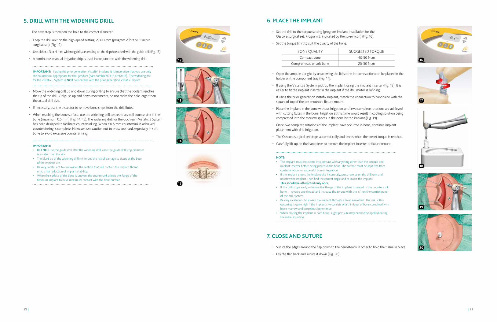
6. PLACE THE IMPLANT
• Setthedrilltothetorquesetting(programImplantinstallationforthe Osscora surgical set: Program 3, indicated by the screw icon) (Fig. 16).
• Setthetorquelimittosuitthequalityofthebone.
• Opentheampuleuprightbyunscrewingthelidsothebottomsectioncanbeplacedintheholder on the component tray (Fig. 17).
• IfusingtheVistafix3System,pickuptheimplantusingtheimplantinserter(Fig.18).Itiseasier to fit the implant inserter in the implant if the drill motor is running.
• IfusingthepriorgenerationVistafixImplant,matchtheconnectiontohandpiecewiththesquare of top of the pre-mounted fixture mount.
• Placetheimplantinthebonewithoutirrigationuntiltwocompleterotationsareachievedwith cutting flutes in the bone. Irrigation at this time would result in cooling solution being compressed into the marrow spaces in the bone by the implant (Fig. 19).
• Oncetwocompleterotationsoftheimplanthaveoccurredinbone,continueimplantplacement with drip irrigation.
• TheOsscorasurgicalsetstopsautomaticallyandbeepswhenthepresettorqueisreached.
• Carefullyliftuponthehandpiecetoremovetheimplantinserterorfixturemount.
NOTE: • Theimplantmustnotcomeintocontactwithanythingotherthantheampuleand implant inserter before being placed in the bone. The surface must be kept free from contamination for successful osseointegration. • Iftheimplantenterstheimplantsiteincorrectly,pressreverseonthedrillunitand unscrew the implant. Then find the correct angle and re-insert the implant. This should be attempted only once. • Ifthedrillstopsearly—beforetheflangeoftheimplantisseatedinthecountersunk bone — reverse one thread and increase the torque with the +/- on the control panel of the drill system. • Beverycarefulnottoloosentheimplantthroughaleverarmeffect.Theriskofthis occurring is quite high if the implant site consists of a thin layer of bone combined with loose marrow and cancellous bone tissue. • Whenplacingtheimplantinhardbone,slightpressuremayneedtobeappliedduring the initial insertion.
7. CLOSE AND SUTURE
• Suturetheedgesaroundtheflapdowntotheperiosteuminordertoholdthetissueinplace.
• Laytheflapbackandsutureitdown(Fig.20).
BONE QUALITY SUGGESTED TORQUECompact bone 40-50 Ncm
Compromised or soft bone 20-30 Ncm16
19
17
18
20
5. DRILL wITH THE wIDENINg DRILL
The next step is to widen the hole to the correct diameter.
• Keepthedrillunitonthehigh-speedsetting:2,000rpm(program2fortheOsscora surgical set) (Fig. 12).
• Useeithera3or4mmwideningdrill,dependingonthedepthreachedwiththeguidedrill(Fig.13).
• Acontinuousmanualirrigationdripisusedinconjunctionwiththewideningdrill.
IMPORTANT: If using the prior generation Vistafix® implant, it is imperative that you use only the countersink appropriate for that product (part number 90416 or 90417). The widening drill for the Vistafix 3 System is NOT compatible with the prior generation Vistafix Implant.
• Movethewideningdrillupanddownduringdrillingtoensurethatthecoolantreaches the tip of the drill. Only use up and down movements, do not make the hole larger than the actual drill size.
• Ifnecessary,usethedissectortoremovebonechipsfromthedrillflutes.
• Whenreachingthebonesurface,usethewideningdrilltocreateasmallcountersinkinthebone (maximum 0.5 mm) (Fig. 14, 15). The widening drill for the Cochlear™ Vistafix 3 System has been designed to facilitate countersinking. When a 0.5 mm countersink is achieved, countersinking is complete. However, use caution not to press too hard, especially in soft bone to avoid excessive countersinking.
IMPORTANT: • DO NOT use the guide drill after the widening drill since the guide drill stop diameter is smaller than the site. • Theblunttipofthewideningdrillminimizestheriskofdamagetotissueatthebase of the implant site. • Beverycarefulnottoover-widenthesectionthatwillcontaintheimplantthreads or you risk reduction of implant stability. • Whenthesurfaceoftheboneisuneven,thecountersinkallowstheflangeofthe titanium implant to have maximum contact with the bone surface.
12
14
13
15
| 2524 |
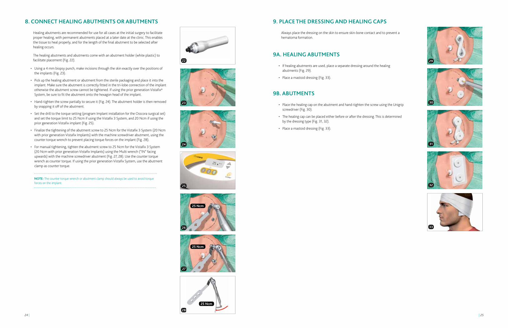
8. CONNECT HEALINg ABUTMENTS OR ABUTMENTS
Healing abutments are recommended for use for all cases at the initial surgery to facilitate proper healing, with permanent abutments placed at a later date at the clinic. This enables the tissue to heal properly, and for the length of the final abutment to be selected after healing occurs.
The healing abutments and abutments come with an abutment holder (white plastic) to facilitate placement (Fig. 22).
• Usinga4mmbiopsypunch,makeincisionsthroughtheskinexactlyoverthepositionsof the implants (Fig. 23).
• Pickupthehealingabutmentorabutmentfromthesterilepackagingandplaceitintotheimplant. Make sure the abutment is correctly fitted in the tri-lobe connection of the implant otherwise the abutment screw cannot be tightened. If using the prior generation Vistafix® System, be sure to fit the abutment onto the hexagon head of the implant.
• Hand-tightenthescrewpartiallytosecureit(Fig.24).Theabutmentholderisthenremovedby snapping it off of the abutment.
• Setthedrilltothetorquesetting(programImplantinstallationfortheOsscorasurgicalset)and set the torque limit to 25 Ncm if using the Vistafix 3 System, and 20 Ncm if using the prior generation Vistafix implant (Fig. 25).
• Finalizethetighteningoftheabutmentscrewto25NcmfortheVistafix3System(20Ncmwith prior generation Vistafix Implants) with the machine screwdriver abutment, using the counter torque wrench to prevent placing torque forces on the implant (Fig. 28).
• Formanualtightening,tightentheabutmentscrewto25NcmfortheVistafix3System (20 Ncm with prior generation Vistafix Implants) using the Multi wrench (“IN” facing upwards) with the machine screwdriver abutment (Fig. 27, 28). Use the counter torque wrench as counter torque. If using the prior generation Vistafix System, use the abutment clamp as counter torque.
NOTE: The counter torque wrench or abutment clamp should always be used to avoid torque forces on the implant.
23
22 29
24
30
27
31
32
3326
25
25 Ncm
25 Ncm
28
25 Ncm
9. PLACE THE DRESSINg AND HEALINg CAPS
Always place the dressing on the skin to ensure skin-bone contact and to prevent a hematoma formation.
9A. HEALINg ABUTMENTS
• Ifhealingabutmentsareused,placeaseparatedressingaroundthehealing abutments (Fig. 29).
• Placeamastoiddressing(Fig.33).
9B. ABUTMENTS
• Placethehealingcapontheabutmentandhand-tightenthescrewusingtheUnigripscrewdriver (Fig. 30).
• Thehealingcapcanbeplacedeitherbeforeorafterthedressing.Thisisdetermined by the dressing type (Fig. 31, 32).
• Placeamastoiddressing(Fig.33).

| 2726 |
Vistafix® two-stage surgeryWhen using the two-stage procedure, auricular tags and remnants are often left in place at the first stage and not removed until the second operation. Subcutaneous tissue reduction is often carried out at stage two of the procedure to ensure successful implantation prior to the tissue reduction.

| 2928 |
First stage of the two-stage surgery1. PREPARE THE SITE
• Thepositionoftheimplantsshouldbeselectedincollaborationwiththeanaplastologistand/or prosthetic team for the best aesthetic and functional outcome.
• Theimplantsitesshouldbecarefullymarked,usingathinneedleorsurgicalink,downtothe bone. The surgeon should use a template, prepared by the anaplastologist, to mark the implant sites prior to the surgical procedure.
Auricular prosthesis• Toobtainagooddepthfortheauricularprosthesistheretentionbarshouldbelocatedunder
the anti-helix part of the prosthesis; therefore the implants should also be located directly under the anti-helix (Fig. 1).
• Twoimplantsareoftensufficientforsatisfactoryretention,thoughthreeimplantsmay be needed for optimal retention. The ideal position is approximately 20 mm from the center of the external ear canal opening or, in the case of the atretic ear, the anticipated opening. On the patient’s left side, the positions are at 4 o’clock and 1:30 (Fig. 2a). On the right side the corresponding positions are at 8 o’clock and 10:30 (Fig. 2b). When using 3 implants, placing the implants at 1:30, 3:00 and 4:30 (for left ear), and 10:30, 9:00 and 7:30 (for a right ear) is appropriate. The distance between the implants should be at least 10 mm to facilitate cleaning around the abutment.
Midface and orbital prosthesis• Whenplacingimplantsintheorbitandinthemidfaceitisveryimportantthatthesurgeon
works with the anaplastologist in detail regarding the positions and directions of the implants. A template may be used in order to achieve a successful result. If not, the final aesthetic result could be jeopardized. It is also critical to consider the position and orientation of the implant in order to obtain a good retention and to facilitate cleaning around the abutment.3
2. MAKE THE INCISION
• Makeanincisionapproximately10mmbehindtheimplantsite.Performasharpdissectiondown to the periosteum. When the periosteum is exposed, a cruciate incision is made (Fig. 3) in the periosteum at each implant site.
NOTE: Electrocoagulation should be used with care in order to minimize tissue trauma.
3. DRILL wITH THE gUIDE DRILL
NOTE: Drilling and placing the implant are generally done in one sequence. It is recommended to start with the inferior implant due to the higher likelihood of air cells in the area. Sections 3-5 in this guide illustrate the drilling and placement of the superior implant.
Be certain to drill at an angle perpendicular to the patient and bone surface. The drill indicator facilitates correct drill orientation and should be used during drilling and implant placement.
• Setthedrillunittothehigh-speedsetting,2,000rpm(program2fortheOsscora surgical set) (Fig. 4).
• Acontinuousmanualirrigationdripisusedinconjunctionwiththewideningdrill.
• Begindrillingwiththeguidedrilland3mmspacer(Fig.5).
• Whiledrilling,movetheburrupanddownandslightlyenlargetheholetoensurevisualinspection, and that the coolant reaches the tip of the drill. Cooling is critical, as an osteocyte will die after 1 minute at 42°C.
• Palpatethebaseoftheimplantsiterepeatedlyforbonepresencewiththedissectorandperform visual inspection (Fig. 6).
• Ifthebonehasadequatethickness,removethewhitespacerontheguidedrillandcontinuedrilling to a depth of 4 mm (Fig. 7). If, however, soft tissue is encountered when drilling with the white spacer, drilling should be terminated and the procedure completed with the 3 mm components.
NOTE: Observe the quality and quantity of the cortical bone and spongiosa air cells during initial penetration. Proceed with care to avoid penetrating the wall of the sigmoid sinus or damaging the dura mater.
4. DRILL wITH THE wIDENINg DRILL
The next step is to widen the hole to the right diameter.
• Keepthedrillunitonthehigh-speedsetting,2,000rpm(program2fortheOsscora surgical set) (Fig. 4).
• Useeithera3or4mmwideningdrill,dependingonthedepthreachedwiththe guide drill (Fig. 8).
IMPORTANT: If using the prior generation Vistafix Implant, it is imperative that you use only the countersink appropriate for that product (part number 90416 or 90417). The widening drill for the Vistafix 3 System is NOT compatible with the prior generation Vistafix Implant.
• Movethewideningdrillupanddownduringdrillingtoensurethatthecoolantreachesthe tip of the drill. Only use up and down movements, do not make the hole larger than the actual drill size.
• Ifnecessary,usethedissectortoremovebonechipsfrequentlyfromthedrillflutes.
• Whenreachingthebonesurface,usethewideningdrilltocreateasmallcountersinkinthebone (maximum 0.5 mm) (Fig. 9, 10). The widening drill for the Cochlear™ Vistafix® 3 System has been designed to facilitate countersinking. When a 0.5 mm countersink is achieved, countersinking is complete. However, use caution not to press too hard, especially in soft bone to avoid excessive countersinking..
IMPORTANT: • DO NOT use the guide drill after the widening drill since the guide drill stop diameter is smaller than the site. • Theblunttipofthewideningdrillminimizestheriskofdamagetotissueatthebottom of the hole. • Beverycarefulnottoover-widenthesectionthatwillcontaintheimplantthreadsoryou risk losing initial implant stability. • Whenthesurfaceoftheboneisuneven,thecountersinkallowstheflangeofthe titanium implant to have maximum contact with the bone surface.
5
4
6
7
9
8
10
Dril
l ind
icat
or
Spac
er
1
2a
2b
3

| 3130 |
Second stage of the two-stage surgery1. REDUCE SUBCUTANEOUS TISSUE
There are three prerequisites for establishing and maintaining a reaction-free skin-penetration. First, the skin surrounding the implants should be hairless to help keep the implant site clean. Second, all subcutaneous tissue may be removed in order to minimize skin mobility in relation to the implant. Third, the soft tissue should be carefully trimmed to its innermost layer (periosteum), and the flap then sutured down to the periosteum.
Attention to detail during skin preparation is vital to avoid tissue and hair regrowth, which can increase the risk of irritation or wound healing problems around the abutment.
• Scrapehairfromtheflap(Fig.17).
• Removeallsubcutaneoustissuewithhairfolliclesundertheskinflaptominimizeskinmobility in relation to the implant (Fig. 18).
• Removesubcutaneoustissueattheperipheryoftheflapholdingthebladeparalleltotheskin(Fig. 19). When the depth of the tissue is about 6 mm it is advisable to remove soft tissue approximately 20 mm outwards from the flap edges. The thicker the subcutaneous tissue is, the larger the reduction should be.
• Trimanyremainingperiosteumthatcanberaiseddowntotheinnermostlayertoavoidregrowth of tissue and to avoid mobility. However, the periosteum must remain intact to maintain the blood supply required for healing (Fig. 20).
• Suturetheflapdowntotheperiosteumatthebaseoftheskinflap.
2. REMOVE THE COVER SCREw
• Usinga4mmbiopsypunch,makeincisionsthroughtheskinexactlyoverthepositions of the implants (Fig. 23).
• LiftuptheflapandremovethecoverscrewsusingthescrewdriverUnigrip95mm(Fig.22).
• Laytheflapbackandsutureitdown(Fig23).
11 17
14 20
12 18
13 19
15
16
21
22
5. PLACE THE IMPLANT
• Setthedrilltothetorquesetting(programImplantinstallationforthe Osscora surgical set: Program 3, indicated by the screw icon.) (Fig. 16).
• Setthetorquelimittosuitthequalityofthebone.
• Opentheampuleuprightbyunscrewingthelidsothebottomsectioncanbeplacedintheholder on the component tray (Fig. 12).
• IfusingtheVistafix3Systempickuptheimplantusingtheimplantinserter(Fig.13).Itiseasier to fit the implant inserter in the implant if the drill motor is running.
• IfusingthepriorgenerationVistafiximplant,matchtheconnectiontohandpiecewiththesquare of top of the pre-mounted fixture mount.
• Placetheimplantwithoutirrigationuntilthefirstthreadsoftheimplantarewellwithinthe bone. Irrigation at this time would result in cooling solution being compressed into the marrow spaces in the bone by the implant (Fig. 14).
• Onceinthebone,continueimplantplacementwithirrigation.
• TheOsscorasurgicalsetstopsautomaticallyandbeepswhenthepresettorqueisreached.
• Carefullyliftupthehandpiecetoremovetheimplantinserterorconnectiontohandpiecefrom the implant.
NOTE: • Theimplantmustnotcomeintocontactwithanythingotherthantheampuleand implant inserter before being placed in the bone. The surface must be kept free from contamination for successful osseointegration. • Iftheimplantenterstheimplantsiteincorrectly,pressreverseonthedrillunitand unscrew the implant. Then find the correct angle and re-insert the implant. This should be attempted only once. • Ifthedrillstopsearly-beforetheflangeoftheimplantisseatedinthecountersunk bone - reverse one thread and increase the torque with the +/- on the control panel of the drill system. • Beverycarefulnottoloosentheimplantthroughaleverarmeffect.Theriskofthis occurring is quite high if the implant site consists of a thin layer of bone combined with loose marrow and cancellous bone tissue. • Whenplacingtheimplantinhardbone,slightpressuremayneedtobeappliedduring the initial insertion.
6. PLACE THE COVER SCREw
Inserting a cover screw protects the internal threads of the implant from tissue and bone overgrowth during the healing phase.
• PlaceandhandtightenthecoverscrewusingthescrewdriverUnigrip95mm(Fig.15).
• Suturedowntheperiosteumwithresorbablesuturesovertheimplant.
• Suturetheflapintoposition(Fig.16).
• Placeamastoiddressing.
BONE QUALITY SUGGESTED TORQUECompact bone 40-50 Ncm
Compromised or soft bone 20-30 Ncm
23

| 3332 |
25
29
28
27
4. PLACE THE DRESSINg AND HEALINg CAPS
Always place the dressing on the skin to ensure skin-bone contact and to prevent a hematoma formation.
4A. HEALINg ABUTMENTS
• Ifhealingabutmentsareused,placeadressingaroundthehealingabutments(Fig.31).
• Placeamastoiddressing(Fig.35).
4B. ABUTMENTS
• Placethehealingcapontheabutmentandhand-tightenthescrewusingtheUnigripscrewdriver (Fig. 32).
• Thehealingcapcanbeplacedeitherbeforeorafterthedressing.Thisisdetermined by the dressing type (Fig. 33, 34).
• Placeamastoiddressing(Fig.35).
31
32
33
34
35
3. CONNECT HEALINg ABUTMENTS OR ABUTMENTS
Healing abutments are typically used during the initial healing stage, with the permanent abutments placed at a later date at the clinic. This enables the tissue to heal properly before the length of the final abutment is chosen.
If permanent abutments are placed at this stage as an alternative to healing abutments, the tissue will alter during healing, and this could mean that a different height abutment may be needed before making the final prosthesis.
The healing abutments and abutments come with an abutment holder (white plastic) to facilitate placement (Fig. 25).
• Pickupthehealingabutmentorabutmentfromthesterilepackagingandplaceitintotheimplant. Make sure the abutment is correctly fitted in the tri-lobe connection of the implant otherwise the abutment screw cannot be tightened. If using the prior generation Vistafix® System, be sure to fit the abutment onto the hexagon head of the implant.
• Hand-tightenthescrewpartiallytosecureit(Fig.26).Theabutmentholderisthenremovedby snapping it off of the abutment.
• Setthedrilltothetorquesetting(programImplantinstallationfortheOsscorasurgicalset)and set the torque limit to 25 Ncm if using the Vistafix 3 System, and 20 Ncm if using the prior generation Vistafix implant (Fig. 27).
• Finalizethetighteningoftheabutmentscrewto25NcmfortheVistafix3System(20Ncmwith prior generation Vistafix implants) with the machine screwdriver abutment, using the counter torque wrench to prevent placing torque forces on the implant (Fig. 28).
• Formanualtightening,tightentheabutmentscrewto25NcmusingtheMultiwrench (“IN” facing upwards) with the machine screwdriver abutment (Fig. 29, 30). Use the counter torque wrench as counter torque. If using the prior generation Vistafix System, use the abutment clamp as counter torque.
NOTE: The counter torque wrench or abutment clamp should always be used to avoid torque forces on the implant.
26
25 Ncm
25 Ncm
25 Ncm
30

| 3534 |
AftercareDressing guidelines
1 day post-op 5-7 days post-op 10-14 days post-op
•Removethemastoiddressing.
•Leavethedressingandhealing cap in situ.
•Ensurethatthepatientdoesnot allow any water to come in contact with the wound for 5–7 days after surgery.
•Removethehealingcap.
•Carefullyremovethedressing.
•Removethesutures(ifapplicable).
•Gentlycleanthewoundwithwaterand gauze.
•Gentlyremoveanydried blood or debris.
•Assessthewoundsiteand treat accordingly.
•Ifhealed,nofurtherdressing is required.
•Applyatopicalantibiotictotheincision and abutment area.
•Providethepatientwithaftercareinstructions and emphasize the importance of daily cleaning.
•Patientcanwashhairifdressing is protected.
•Ifnecessary,repeatrelevantstepsas in the previous visit.
•Ifthewoundsitehasnothealed,consult a wound care specialist.
•Patientcanwashhair.
Patient aftercare instructionsThe prosthesis can be worn for all normal activities including swimming and sports. It may be advisable to remove it and wear some protection, for example a headband, over the bar if you take part in contact sports. The prosthesis should be removed when sleeping.
Good hygiene is critical to maintaining normal usage of the prosthesis. Patients who are unable to clean the skin around the abutment need help from their family or caregivers.
In case of infection, cleaning routines should be checked. If infection persists, it may be controlled by applying a course of topical antimicrobial cream to the skin surrounding the abutment. Topical antimicrobial cream may be administered by wrapping ointment-soaked ribbon gauze around the abutment when positioning the healing cap.
Daily care – the abutment areaThe area around the abutment should be cleaned on a daily basis to avoid debris build up. A soft cleaning brush (Fig. 1), or non-alcohol wipes (such as unscented wipes) can be used around the base of abutment. The soft cleaning brush (obtained from the clinic) should be changed every 3 months. Cleaning this area is most easily done when the patient takes a bath or takes a shower as plenty of warm water and soap on the area will help to soften any crust that may have developed around the base of the abutment. Any mild soap or shampoo may be used, but some recipients have found anti-dandruff shampoo particularly effective.
Care of the prosthesisThe prosthesis should be cleaned regularly by gently brushing with soap and water. Abrasive powders and bleaches should be avoided. The edges of the prosthesis are very thin, so care must be taken when handling it. In the early stages following the fitting of the prosthesis there should be regular visits to the outpatient clinic to make sure that all is well. The patient should be instructed to contact a Vistafix health professional if experiencing any persistent irritation, soreness or inflammation around the abutment.
Hair CarePatients who wish to have their hair permed or colored should remove the prosthesis and protect the abutments with a small amount of cotton wool and cling film secured with a small elastic band. This will prevent the solution or dye from irritating the tissue around the abutment. The hair should not be permed or colored until the surgical site is fully healed.
1
| 3736 |
Complications and troubleshootingThe success rate for Vistafix surgery is very high, however, unexpected situations, both intra-operatively and postoperatively, may occur. Below is a list of potential complications and recommendations for handling them. Importantly, the patient must be informed of all complications related to safety and effectiveness prior to surgery.
The regulation of medical devices requires the manufacturer to report adverse events to the appropriate authority. Should such an incident occur, notify your local Cochlear™ office or its official distributor as soon as possible.
Complications during surgery
The implant becomes stuck during insertionThis can occur if the implant alignment is incorrect. Set the drill unit to reverse mode before unscrewing the implant. Find the correct alignment and re-insert the implant. If the same happens again, select a new implant site nearby.
The implant continues to rotate when the flange is downThis happens most often when dealing with compromised and soft bone, and when the torque is set too high in relation to the quality of the bone. Prepare a new implant site at least 5 mm from the first site and then place the implant with lower torque.
Exposure of dura mater and perforation of the sigmoid sinusAlthough rare, a mild CSF or blood leak can occur during guide hole drilling. If this occurs, it is a low pressure system that can be sealed easily. For a patient with good bone volume, place the implant to seal the leak. If the bone is too thin, choose a new implant site at least 5 mm from the original site (as close as possible as long as the two sites don’t intersect), after sealing the leak with soft tissue or bone wax.
Subdural hematomaThis condition, caused by venous bleeding under the dura, is rare and typically slow developing. It is not often identified during surgery, but is more likely caused by direct trauma and will develop gradually over time and give general neurological symptoms.Should this occur, a CT or MRI can be used to verify the diagnosis. Treat this condition according to general practice.
Postoperative soft tissue complications
Inflammation and infection around the abutmentPoor or excessive personal hygiene is a common reason for skin irritation, but irritation could also be due to movement of the skin caused by a too thick soft tissue layer, a loose abutment, or insufficient osseointegration.
If the skin around the abutment becomes inflamed, thoroughly clean the entire implant site and, if appropriate, apply antimicrobial ointment/cream. Provide the patient with the appropriate aftercare instructions.
Persistent soft tissue complicationsWhen patients have a persistent problem around the abutment, remove the abutment and clean the skin thoroughly. Perform a culture before providing the appropriate antimicrobial and anti-inflammatory treatment. A steroid ointment can also be used. Allow the area to heal for 1–2 weeks before placing a new abutment.
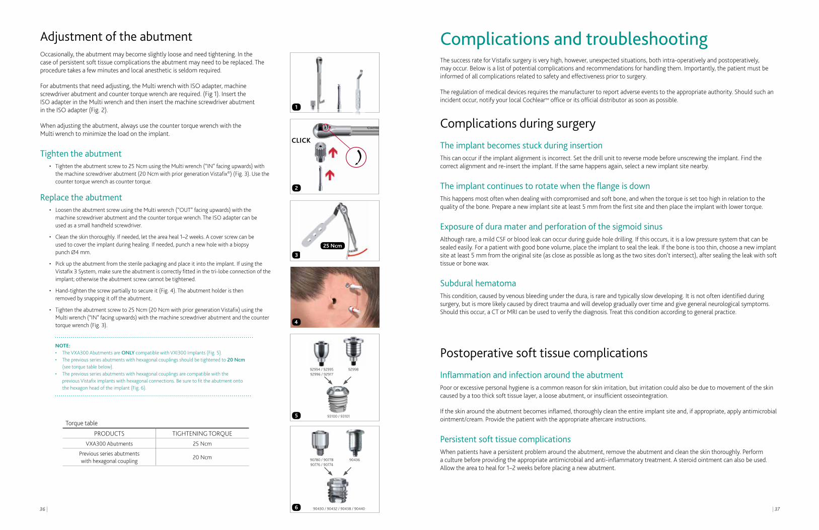
Adjustment of the abutmentOccasionally, the abutment may become slightly loose and need tightening. In the case of persistent soft tissue complications the abutment may need to be replaced. The procedure takes a few minutes and local anesthetic is seldom required.
For abutments that need adjusting, the Multi wrench with ISO adapter, machine screwdriver abutment and counter torque wrench are required. (Fig 1). Insert the ISO adapter in the Multi wrench and then insert the machine screwdriver abutment in the ISO adapter (Fig. 2).
When adjusting the abutment, always use the counter torque wrench with the Multi wrench to minimize the load on the implant.
Tighten the abutment• Tightentheabutmentscrewto25NcmusingtheMultiwrench(“IN”facingupwards)with
the machine screwdriver abutment (20 Ncm with prior generation Vistafix®) (Fig. 3). Use the counter torque wrench as counter torque.
Replace the abutment• LoosentheabutmentscrewusingtheMultiwrench(“OUT”facingupwards)withthe
machine screwdriver abutment and the counter torque wrench. The ISO adapter can be used as a small handheld screwdriver.
• Cleantheskinthoroughly.Ifneeded,lettheareaheal1–2weeks.Acoverscrewcanbe used to cover the implant during healing. If needed, punch a new hole with a biopsy
punch Ø4 mm.
• Pickuptheabutmentfromthesterilepackagingandplaceitintotheimplant.IfusingtheVistafix 3 System, make sure the abutment is correctly fitted in the tri-lobe connection of the implant; otherwise the abutment screw cannot be tightened.
• Hand-tightenthescrewpartiallytosecureit(Fig.4).Theabutmentholderisthen removed by snapping it off the abutment.
• Tightentheabutmentscrewto25Ncm(20NcmwithpriorgenerationVistafix)usingtheMulti wrench (“IN” facing upwards) with the machine screwdriver abutment and the counter torque wrench (Fig. 3).
NOTE: • TheVXA300AbutmentsareONlycompatiblewithVXI300Implants(Fig.5). • Thepreviousseriesabutmentswithhexagonalcouplingsshouldbetightenedto20 Ncm (see torque table below). • Thepreviousseriesabutmentswithhexagonalcouplingsarecompatiblewiththe previous Vistafix implants with hexagonal connections. Be sure to fit the abutment onto the hexagon head of the implant (Fig. 6).
93100 / 93101
92994 / 92995 92996 / 92977
90780 / 90778 90776 / 90774
90436
92998
90430 / 90432 / 90438 / 90440
4
5
6
3
2
1
25 Ncm
CLICK
Torque table
PRODUCTS TIGHTENING TORQUEVXA300Abutments 25 Ncm
Previous series abutmentswith hexagonal coupling
20 Ncm

| 3938 |
Skin overgrowthIf the skin grows back to its original thickness, skin reduction surgery is indicated. In some patients (predominantly male teenagers) an inflammatory reaction may occur and result in complete overgrowth of the abutment by soft tissue. Treatment with topical steroid cream or a steroid injection may be considered.4,5
Persistent skin overgrowthUse a longer abutment if a patient has persistent regrowth of the subcutaneous tissue, which is common in patients with very thick skin.
KeloidsIn the case of keloids that do not subside over time, place a silicone disc over the keloid and keep pressure on the silicone disc for 7–10 days.
Skin flap necrosisSkin flap necrosis can occur within the immediate postoperative period. Simply remove any necrotic tissue and apply a mild antibiotic ointment. Systemic antibiotic treatment is an alternative. Major or even total flap necrosis will often heal, but this could take several months. A skin graft is seldom required.
Postoperative numbness — parasthesiaPostoperative numbness after tissue reduction may occur. Usually this will disappear after a few months. For those who have had significant amounts of subcutaneous tissue removed this may be permanent.
Postoperative bone tissue complications
Implant lossPotential causes of the failure of osseointegration include lack of adequate bone quantity/quality, trauma, infection, generalized diseases and surgical complications.
Bony overgrowthThe potential for a bony overgrowth around the implant increases in children who are implanted. Removal of some bone at the time of soft tissue revision surgery will allow maximum clearance between the skin and the lateral surface of the abutment.
Pain when touching the abutmentIf the patient experiences pain when touching the abutment, there may be an increased risk of implant loss. In most cases, the loose implant can be removed and another one placed in adjacent bone. In others, the implant must be removed and the defect then carefully curetted and filled with blood coagulates. In most cases adjacent bone is available and suitable for the placement of another implant.
Bone infection leading to osteonecrosisThis is seen almost exclusively in patients with previously irradiated implant sites.
Special considerations
MRI and magnetic fieldsBe certain to caution patients about procedures such as MRI and any others involving magnetic fields. Patients fitted with facial or auricular prostheses can undergo an MRI, as long as the prosthesis and the bar construction, any fixation magnets, magnabutments or magnacaps attached to the implants are removed prior to the procedure. This will eliminate the risk of implant loss and minimize the artifacts. The implant itself and the abutment are not ferromagnetic and will not cause any problems for the patient during an MRI 6-8 (up to 3T).
Radiation therapyIf a patient already has implants placed, and is scheduled for radiation therapy around the implant areas, the abutments should be removed but implants could be left in place to allow healing of the site before radiation is performed. A cover screw can be used to cover the implant until the abutment is replaced.
Sporting activitiesIt is important to educate the parents and caregivers about the need for helmets and other safety precautions during sporting activities to minimize traumatic events. Traumatic implant loss can still occur across all age groups.
| 4140 |
Making and fitting the prosthesis
| 4342 |
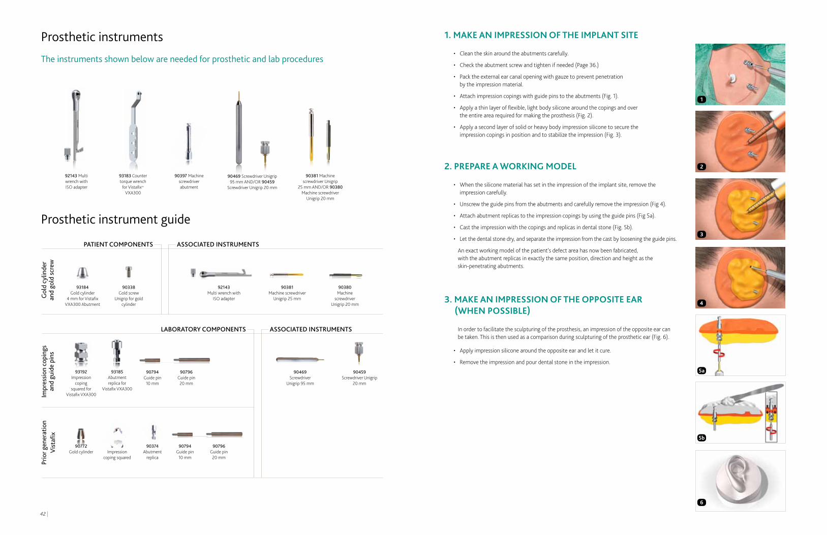
1. MAKE AN IMPRESSION OF THE IMPLANT SITE
• Cleantheskinaroundtheabutmentscarefully.
• Checktheabutmentscrewandtightenifneeded(Page36.)
• Packtheexternalearcanalopeningwithgauzetopreventpenetration by the impression material.
• Attachimpressioncopingswithguidepinstotheabutments(Fig.1).
• Applyathinlayerofflexible,lightbodysiliconearoundthecopingsandover the entire area required for making the prosthesis (Fig. 2).
• Applyasecondlayerofsolidorheavybodyimpressionsiliconetosecurethe impression copings in position and to stabilize the impression (Fig. 3).
2. PREPARE A wORKINg MODEL
• Whenthesiliconematerialhassetintheimpressionoftheimplantsite,removetheimpression carefully.
• Unscrewtheguidepinsfromtheabutmentsandcarefullyremovetheimpression(Fig4).
• Attachabutmentreplicastotheimpressioncopingsbyusingtheguidepins(Fig5a).
• Casttheimpressionwiththecopingsandreplicasindentalstone(Fig.5b).
• Letthedentalstonedry,andseparatetheimpressionfromthecastbylooseningtheguidepins.
An exact working model of the patient’s defect area has now been fabricated, with the abutment replicas in exactly the same position, direction and height as the skin-penetrating abutments.
3. MAKE AN IMPRESSION OF THE OPPOSITE EAR (wHEN POSSIBLE)
In order to facilitate the sculpturing of the prosthesis, an impression of the opposite ear can be taken. This is then used as a comparison during sculpturing of the prosthetic ear (Fig. 6).
• Applyimpressionsiliconearoundtheoppositeearandletitcure.
• Removetheimpressionandpourdentalstoneintheimpression.
Prosthetic instruments
The instruments shown below are needed for prosthetic and lab procedures
2
1
4
3
5a
5b
PATIENT COMPONENTS
lABORATORy COMPONENTS
Gol
d cy
linde
r an
d go
ld s
crew
Impr
essi
on c
opin
gs
and
guid
e pi
nsPr
ior g
ener
atio
n V
ista
fix
ASSOCIATED INSTRUMENTS
ASSOCIATED INSTRUMENTS
90380 Machine
screwdriver Unigrip 20 mm
Prosthetic instrument guide
90469 Screwdriver Unigrip 95 mm AND/OR 90459
Screwdriver Unigrip 20 mm
93183 Counter torque wrench
for Vistafix™ VXA300
92143 Multi wrench with ISO adapter
90381 Machine screwdriver Unigrip
25 mm AND/OR 90380 Machine screwdriver
Unigrip 20 mm
90397 Machine screwdriver abutment
90381 Machine screw driver
Unigrip 25 mm
92143 Multi wrench with
ISO adapter
90338 Gold screw
Unigrip for gold cylinder
93184 Gold cylinder
4 mm for Vistafix VXA300Abutment
90469 Screwdriver
Unigrip 95 mm
90459 Screwdriver Unigrip
20 mm
90794 Guide pin
10 mm
90796 Guide pin 20 mm
90794 Guide pin
10 mm
90796 Guide pin 20 mm
93192 Impression
coping squared for
VistafixVXA300
93185 Abutment replica for
VistafixVXA300
6
90374 Abutment
replica
90379 Impression
coping squared
90772 Gold cylinder

| 4544 |
6. SCULPT AND FIT THE wAx MODEL
• Sculptawaxmodeloftheprosthesis(Fig.13).
TIP: If available, use the impression of the opposite ear as a guide when sculpting the wax model or scan the opposite plaster ear and reverse.
• Softenthewaxmodelandpositionthewaxearontotheacrylicplateonthepatient(Fig.14).
• Makesurethatthereisa2mmspacebetweentheskinandthebackoftheplate/prosthesis.The skin must have access to air in order to prevent irritation due to moisture accumulation.
• Checkthemodel’sfitfromallangleswiththepatient’smouthopenandclosed,movingtheirface and standing up/sitting down.
• Theanteriormarginofthewaxearshouldbemadeverythin.
7. MAKE THE PLASTER MOLD
• Placeabutmentreplicasontothegoldcylindersofthebarconstructionandpositionthebarand abutment replicas into the clips of the acrylic plate (Fig. 15).
• Fabricateathree-pieceplastermold(Fig.16).Embedthefittingsideofthewaxearandbarinto plaster. Separate the plaster with a separating agent. Make key holes in the mold to ensure correct fit between the parts. Pour the second part of the mold up to the middle of the helix. Use the separation agent and make key holes and pour the third part of the mold with plaster.
• Oncethemoldisset,separatethemoldpiecesbyusinghot/boilingwater(Fig.17).
4. DESIgN THE FRAMEwORK
At this stage, the design of the framework is determined and a drawing of the shape of the bar construction is made.
• Placethegoldcylindersontheabutmentreplicasoftheworkingmodel(Fig.7). Tighten the gold screws to 10 Ncm using the Multi wrench with ISO adapter and the machine screwdriver Unigrip.
• CutandgrindaØ2mmgoldalloybarsothatitstretchesbetweenandbeyondtheabutments with an appropriate shape (Fig. 8).
NOTE: It is desirable to place the bar under the anti-helix part of the ear (Fig. 8). In order to minimize torque on the implants the bar should not extend more than 8–10 mm beyond the abutments (Fig. 9).
• Attachthebartothegoldcylinderswithstickywaxoracrylic(Fig.10).
• Removethebarconstructionfromtheworkingmodelandembeditintheinvestment in preparation for soldering (Fig. 10).
• Solderthebartothegoldcylinders.Aweldingtechniquecanalsobeused.
• Checkthebarconstructioncarefullyontheworkingcastandonthepatient for a perfect fit.
5. MAKE THE ACRyLIC PLATE
• Placethebarconstructionontheworkingmodelandpositiontheretentionclipsonthebar.
• Makeanundercutblockwithwaxtopreventthefinishedacrylicplatefromtouchingtheskin.Make sure that the sides of the clips are protected by wax from the acrylic resin. This will facilitate their activation and adjustment (Fig. 11).
• Pourauto-polymerizingacrylicresinoverthebarandclipconstruction(Fig.12).Maketheacrylic plate as flat as possible so as not to compromise the shape of the prosthesis.
TIP: Reinforce the plate with fibers to minimize the risk of breakage.
• Trytheacrylicresinplateonthepatienttoverifyfitandcontours.
8
13
11
12
16
10
14
15
17
7
9
| 4746 |
8. PRIME THE ACRyLIC PLATE
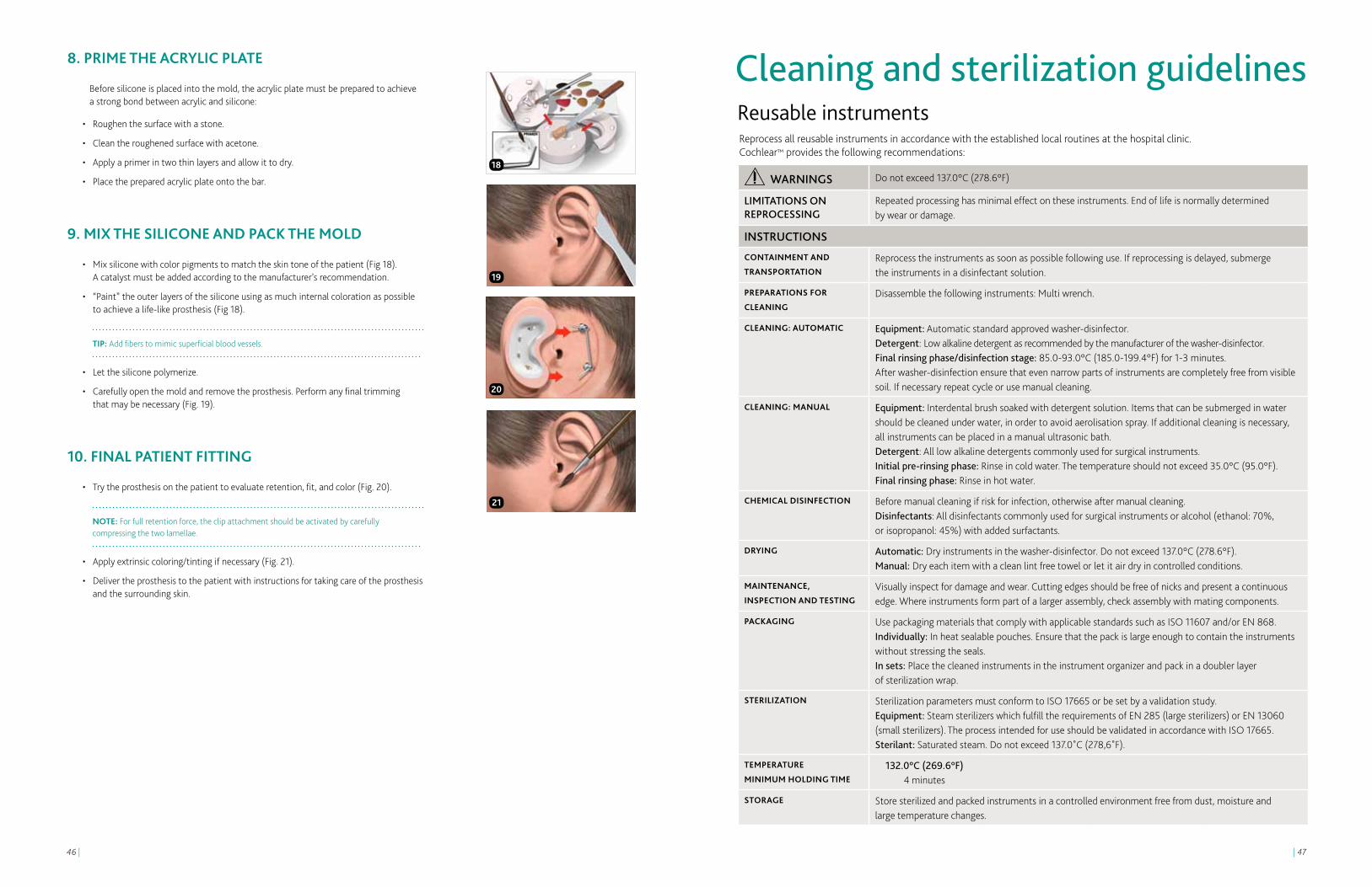
Before silicone is placed into the mold, the acrylic plate must be prepared to achieve a strong bond between acrylic and silicone:
• Roughenthesurfacewithastone.
• Cleantheroughenedsurfacewithacetone.
• Applyaprimerintwothinlayersandallowittodry.
• Placethepreparedacrylicplateontothebar.
9. MIx THE SILICONE AND PACK THE MOLD
• Mixsiliconewithcolorpigmentstomatchtheskintoneofthepatient(Fig18). A catalyst must be added according to the manufacturer’s recommendation.
• “Paint”theouterlayersofthesiliconeusingasmuchinternalcolorationaspossible to achieve a life-like prosthesis (Fig 18).
TIP: Add fibers to mimic superficial blood vessels.
• Letthesiliconepolymerize.
• Carefullyopenthemoldandremovetheprosthesis.Performanyfinaltrimming that may be necessary (Fig. 19).
10. FINAL PATIENT FITTINg
• Trytheprosthesisonthepatienttoevaluateretention,fit,andcolor(Fig.20).
NOTE: For full retention force, the clip attachment should be activated by carefully compressing the two lamellae.
• Applyextrinsiccoloring/tintingifnecessary(Fig.21).
• Delivertheprosthesistothepatientwithinstructionsfortakingcareoftheprosthesis and the surrounding skin.
18
21
19
20
Cleaning and sterilization guidelines
WARNINGS Do not exceed 137.0°C (278.6°F)
lIMITATIONS ON REPROCESSING
Repeated processing has minimal effect on these instruments. End of life is normally determined by wear or damage.
INSTRUCTIONS
CONTAINMENT AND
TRANSPORTATIONReprocess the instruments as soon as possible following use. If reprocessing is delayed, submerge the instruments in a disinfectant solution.
PREPARATIONS FOR
CLEANINgDisassemble the following instruments: Multi wrench.
CLEANINg: AUTOMATIC Equipment: Automatic standard approved washer-disinfector.Detergent: Low alkaline detergent as recommended by the manufacturer of the washer-disinfector.Final rinsing phase/disinfection stage: 85.0-93.0°C (185.0-199.4°F) for 1-3 minutes.After washer-disinfection ensure that even narrow parts of instruments are completely free from visible soil. If necessary repeat cycle or use manual cleaning.
CLEANINg: MANUAL Equipment: Interdental brush soaked with detergent solution. Items that can be submerged in water should be cleaned under water, in order to avoid aerolisation spray. If additional cleaning is necessary, all instruments can be placed in a manual ultrasonic bath.Detergent: All low alkaline detergents commonly used for surgical instruments.Initial pre-rinsing phase: Rinse in cold water. The temperature should not exceed 35.0°C (95.0°F).Final rinsing phase: Rinse in hot water.
CHEMICAL DISINFECTION Before manual cleaning if risk for infection, otherwise after manual cleaning. Disinfectants: All disinfectants commonly used for surgical instruments or alcohol (ethanol: 70%, or isopropanol: 45%) with added surfactants.
DRyINg Automatic: Dry instruments in the washer-disinfector. Do not exceed 137.0°C (278.6°F).Manual: Dry each item with a clean lint free towel or let it air dry in controlled conditions.
MAINTENANCE,
INSPECTION AND TESTINgVisually inspect for damage and wear. Cutting edges should be free of nicks and present a continuous edge. Where instruments form part of a larger assembly, check assembly with mating components.
PACKAgINg Use packaging materials that comply with applicable standards such as ISO 11607 and/or EN 868.Individually: In heat sealable pouches. Ensure that the pack is large enough to contain the instruments without stressing the seals. In sets: Place the cleaned instruments in the instrument organizer and pack in a doubler layer of sterilization wrap.
STERILIzATION Sterilization parameters must conform to ISO 17665 or be set by a validation study. Equipment: Steam sterilizers which fulfill the requirements of EN 285 (large sterilizers) or EN 13060 (small sterilizers). The process intended for use should be validated in accordance with ISO 17665. Sterilant: Saturated steam. Do not exceed 137.0˚C (278,6˚F).
TEMPERATURE
MINIMUM HOLDINg TIME132.0°C (269.6°F)
4 minutes
STORAgE Store sterilized and packed instruments in a controlled environment free from dust, moisture and large temperature changes.
Reprocess all reusable instruments in accordance with the established local routines at the hospital clinic. Cochlear™ provides the following recommendations:
Reusable instruments

Cochlear and the elliptical logo are trademarks of Cochlear Limited. Hear now. And always and Nucleus are registered trademarks of Cochlear Limited. Baha and Vistafix are registered trademarks of Cochlear Bone Anchored Solutions AB, a Cochlear Group Company. The names of actual companies and products mentioned herein may be the trademarks of their respective owners. © Cochlear Limited 2012.
VFX001 ISS1 MAY12
REFEREnCES
1. Westin T, Tjellström A, Hammerlid E, BergströmK,RangertB.Long-termstudyof quality and safety of osseointegration for the retention of auricular prostheses. Otolaryngology; Head and Neck Surgery. 1999; 121(1): 133-43.
2. Sennerby L, Meredith N. Implant stability measurements using resonance frequency analysis: biological and biomechanical aspects and clinical implications. Periodontology. 2000; 47:51-66.
3. Reisberg D, Habakuk S. Use of a surgical positioner for bone-anchored facial prosthesis. 1997; 12:376-379.
4. FalconeMT,KaylieDM,LabadieRF,HaynesDS. Bone-anchored hearing aid abutment skin overgrowth reduction with clobetasol. Otolaryngology; Head and Neck Surgery. 2008; 139(6):829-32.
5. Ghossaini SN, Spitzer JB. Local steroid injections in the management of skin growth over the abutment in Baha patients. Otolaryngology; Head and Neck Surgery. 2009; 141(4):530-2.
6. Devge C, Tjellström A, Nellström H. Magnetic resonance imaging in patients with dental implants: a clinical report. 1997;12(3):354-9.
7. FritschMH,NaumannIC,Mosier,KM.Bahadevices and magnetic resonance imaging scanners. Otology & Neurotology. 2008; 29(8):1095–9.
8. ArndtS,KromeierJ,BerlisA,MaierW,LaszigR, Aschendorff, A. Imaging procedures after bone anchored hearing aid implantation. Laryngoscope. 2007; 117(10):1815–8.
Cochlear Americas13059 East Peakview AvenueCentennial CO 80111USA
Tel: 1 303 790 9010 Fax: 1 303 792 9025
Cochlear Canada Inc2500-120 Adelaide Street WestToronto, ON M5H 1T1 Canada
Tel: 1 416 972 5082 Fax: 1 416 972 5083
www.CochlearAmericas.com
As your patient’s partner, Cochlear™ believes it is important to convey not only the benefits, but also the potential risks associated with a Cochlear Vistafix® procedure.
Vistafix is contraindicated in patients with inadequate bone quality or quantity to provide stability and support for the implant, or in patients who will be unable to maintain and clean the skin around the abutment. In the U.S. and Canada, use of the implanted fixture is also contraindicated in children under age five years.
All surgical procedures include an element of risk, and it is impossible to guarantee success. The device may fail to osseointegrate for a number of reasons, including physiological and surgical issues as well as traumatic impact to the implant site. On rare occasions the skin around the abutment may become inflamed from a mild infection or the skin may grow back towards its original thickness. For complete information regarding the risks and benefits of a Vistafix procedure, please refer to the Instructions for use for the Vistafix implant available at www.CochlearAmericas.com/VistafixIndications