trb webinar: encouraging innovation in locating...
TRANSCRIPT

TRB Webinar: Encouraging Innovation in Locating & Characterizing Underground Utilities

Today’s Presenter and Moderator
Raymond Sterling, Louisiana Tech University, [email protected]
Monica Starnes, Transportation Research Board, [email protected]

Download the Reporthttp://onlinepubs.trb.org/onlinepubs/shrp2/shrp2_S2-R01-RW.pdf

R. Sterling, J. Anspach, E. Allouche, J. Simicevic, C. Rogers
Findings from a Research Project carried out for the TRANSPORTATION RESEARCH BOARD NAS-NRC
By the Trenchless Technology CenterLouisiana Tech University
Contract # SHRP-R-01

1. The project2. Urban utility issues3. Utility locating and characterization for
transportation projects4. Utility locating technology developments5. Utility characterization technology
developments6. Ongoing and future research7. Preliminary tour of website

Encouraging Innovation in Locating and characterizing Underground Utilities
Web-based tool: quick technology reference
Products Report documenting◦ frequent barriers in locating and characterizing underground
utilities.◦ currently available techniques and practices◦ technologies potentially useful
R&D Plan
Focus on Identifying technologies to better locate and identify underground utilities and developing a research plan that will encourage their development

Monica A. Starnes, PhD (SHRP 2 Project Manager) Raymond L. Sterling, PhD, P.E. (Principal
Investigator), TTC E. Allouche, PhD, P.Eng., TTC James H. Anspach, P.G., So-Deep, Inc. K. Weston, P.E., Transportation Design
Consultant) Chris Rogers, PhD, C.Eng., University of
Birmingham, U.K. Kate Hayes, Nat. Agric. Lib. (retired) Jadranka Simicevic, Research Engineer, TTC John Matthews, Ph.D. candidate, TTC Joseph Berchmans, Consultant Programmer

More than 11 million miles in U.S.Existing investment in the trillions of dollarsHaphazard, poorly documented, neglected
Wall Street NY 1918


France

Horizontal directional drilling◦ Remarkable advances in
installation technology◦ Utility location issues Plastic pipe Curved alignment Depth easily increased◦ Utility damage issues Cross-bores
Courtesy: Ditchwitch

Differences between damage prevention and effective management of utility information for transportation projects
Utility coordination issues dealt with in a separate SHRP 2 project
Subsurface Utility Engineering approaches important issues in both studies

Geophysical technology used to detect and image underground utilities
Processes, procedures, and techniques used by the field technicians in collecting the geophysical data in the field

Means and methods of transferring data from the instrumentation to the data users
Other sources of information regarding utility location, such as visual observation and/or existing records
Integration and validation of data sources
Formatting and display of data to the data users
Retention of and record-keeping practices for the data
Use of the recorded data for the next “locating” exercise at this location

STANDARD GUIDELINE FOR THE COLLECTION AND DEPICTION OF
EXISTING SUBSURFACE UTILITY DATA
C-I /ASCE 38-02
Chairman ASCE C/I 38-02 – J.H. Anspach
[email protected] 541-678-2151

Plotted on plans from records. Sometimes a field visit - to look for utility
indications on the site - is made. Sometimes “verbal recollections” are plotted.
The least reliable data
Courtesy, J. Anspach and So-Deep

Curb / EOP
Courtesy, J. Anspach and So-Deep

Curb / EOP
Water Record says 4” pipe is two feet off of curb
Courtesy, J. Anspach and So-Deep

Surface Appurtenances are surveyed and accurately plotted on a current site plan
Utility data from records (QL D) are correlated to the appurtenances
“Quality Level C”The “traditional” utility depiction
Courtesy, J. Anspach and So-Deep

Curb / EOP
Courtesy, J. Anspach and So-Deep

Curb / EOP
Water Record says 4” pipe is two feet off of curb
Courtesy, J. Anspach and So-Deep

Curb / EOP
Water Record says pipe is two feet off of curb, but
Valves are 6 feet off curb
Surveyed & Plotted Water Valves
Courtesy, J. Anspach and So-Deep

Curb / EOP
Water Record says pipe is two feet off of curb.
Engineer makes judgment that water line depiction should be moved
Surveyed & Plotted Water Valves
Courtesy, J. Anspach and So-Deep

Curb / EOP
Water Record says pipe is two feet off of curb.
Engineer makes judgment that water line depiction should be moved
Surveyed & Plotted Water Valves
Courtesy, J. Anspach and So-Deep

Curb / EOP
Water Record says pipe is two feet off of curb.
Engineer makes judgment that water line depiction should be re-configured.
Surveyed & Plotted Water Valves
Courtesy, J. Anspach and So-Deep
OR

Surface Geophysical Methods used to search for and trace existing utilities.
Designated utilities are then surveyed and plotted on site plan.
“Quality Level B”A significant upgrade in quality
Courtesy, J. Anspach and So-Deep

Curb / EOP
Courtesy, J. Anspach and So-Deep

Curb / EOP
Water Record says 4” pipe is two feet off of curb
Courtesy, J. Anspach and So-Deep

Curb / EOP
Water Record says pipe is two feet off of curb.
Designating indicates otherwise.
Surveyed & Plotted Water Valves
QL D and QL C interpretationsBy engineer were in error
Courtesy, J. Anspach and So-Deep

Utilities exposed via non-destructive air-vacuum means
Exposed utilities are then surveyed and plotted on site plan Elevations, Size, Condition, Materials, Precise Horizontal Positions are measured and documented
“Quality Level A”A Guarantee in 3-D
Courtesy, J. Anspach and So-Deep

Ground surface
Water line found at CL Station 23+40, L10to be 6 3/4” in diameter and 5.56’ deep, slightly corroded and cast iron rather than ductile
Courtesy, J. Anspach and So-Deep

The end result is a map suitable for current needs, and retrievable for future needs, with the reliability of the utilities clearly indicated
Courtesy, J. Anspach and So-Deep

Technological◦ Surface geophysical equipment◦ Data processing◦ Survey / data retention
Social◦ Training
Political◦ Policies, statutes◦ Ratepayer v. taxpayer

Most studied object in history
Consists of widely different materials
Research into imaging in the billions of dollars for CAT, Ultrasound, MRI, etc.
Highly controlled imaging environment
Great records
No one method works for everything
Exploratory surgery still common
Highly trained interpreters of data

Single multi-sensor system Locates all types of utilities Does not require prior knowledge of
approximate location or access to utility Can operate in urban conditions in street
right-of-way Covers necessary range of depths and utility
diameters Has acceptable cost

Geophysical Methods◦ Electromagnetic Methods◦ Resistivity Measurements◦ Magnetic Methods◦ Elastic Waves (Acoustics / Sound / Mechanical)◦ Borehole Geophysics◦ Data-Processing Techniques
Marker Methods◦ Passive markers◦ RFID markers
Excavation Methods of Locating Data Management◦ Record generation during utility installation◦ Record updates and maintenance

Introduce wave or signal into ground
Response affected by physical properties of object located in the ground
Information about the properties of the object and its location is inferred from the response
Courtesy of N. Simicevic, Louisiana Tech Univ.
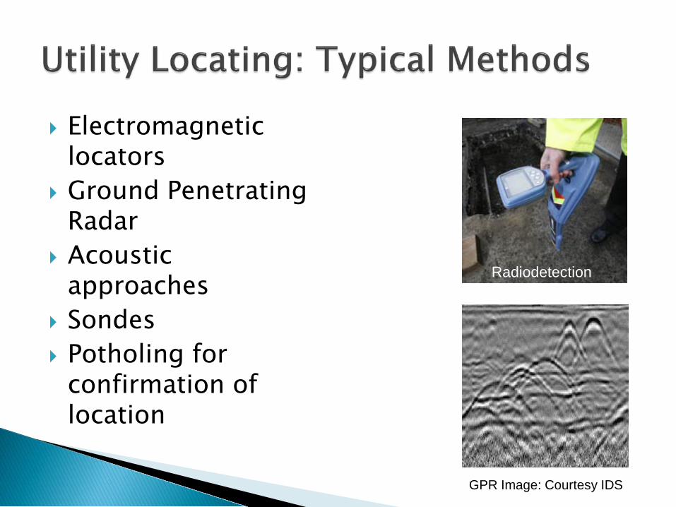
Electromagnetic locators
Ground Penetrating Radar
Acoustic approaches
Sondes Potholing for
confirmation of location
GPR Image: Courtesy IDS
Radiodetection
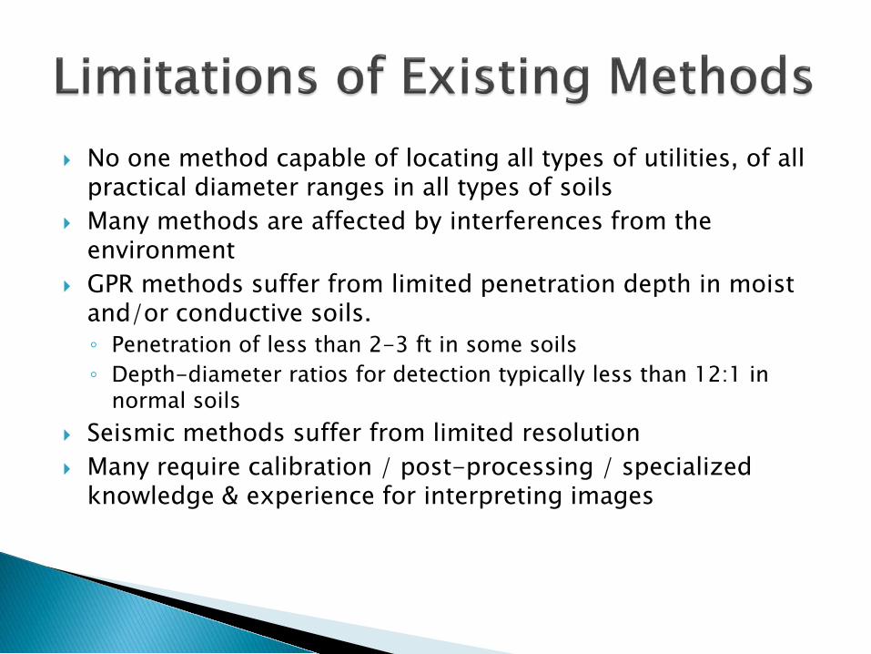
No one method capable of locating all types of utilities, of all practical diameter ranges in all types of soils
Many methods are affected by interferences from the environment
GPR methods suffer from limited penetration depth in moist and/or conductive soils.◦ Penetration of less than 2-3 ft in some soils◦ Depth-diameter ratios for detection typically less than 12:1 in
normal soils Seismic methods suffer from limited resolution Many require calibration / post-processing / specialized
knowledge & experience for interpreting images
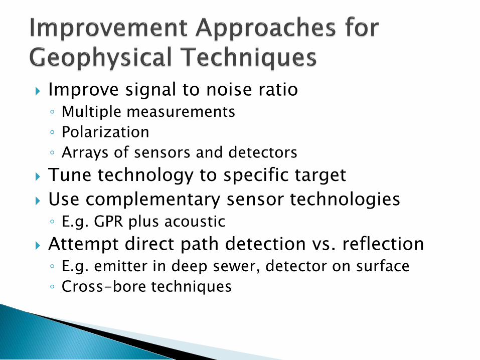
Improve signal to noise ratio◦ Multiple measurements◦ Polarization◦ Arrays of sensors and detectors
Tune technology to specific target Use complementary sensor technologies◦ E.g. GPR plus acoustic
Attempt direct path detection vs. reflection◦ E.g. emitter in deep sewer, detector on surface◦ Cross-bore techniques

Detector moves within potential detection zone Speed of identification and reaction still an issue Does not help with transportation planning

Recent GPS/GIS innovations allow rapid and accurate mapping of surface features of utility systems
Combined with 3-D profile mapping of u/g pipes, offers the ability to build accurate 3-D maps of buried utilities
Guardian Prostar

Mapping the Underworld / VISTA ORFEUS / GIGA OPS / PHMSA Multi-sensor platform development Utility locating test sites◦ Europe◦ USA◦ Brazil

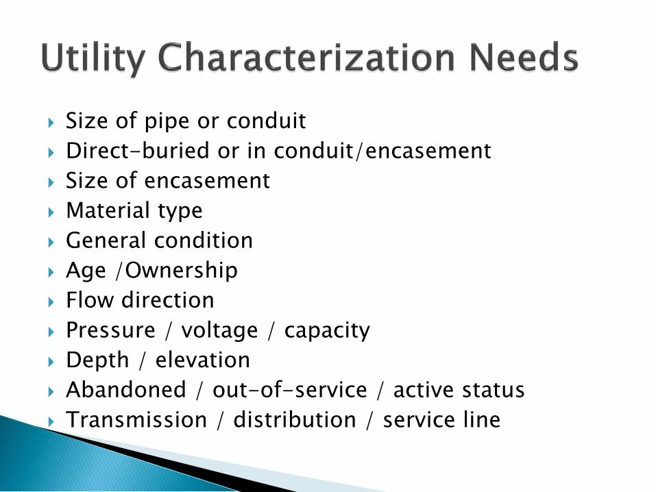
Size of pipe or conduit Direct-buried or in conduit/encasement Size of encasement Material type General condition Age /Ownership Flow direction Pressure / voltage / capacity Depth / elevation Abandoned / out-of-service / active status Transmission / distribution / service line


High quality images
Ability to see water flow, etc.

High resolution, high rate 360º images
Virtual video PTZ at any point
IntegrityMetadata always travels with inspection dataGPS coordinates stored on robot when launched
Coded in a controlled environment
High efficiencyQuality auditsAutomation
Courtesy: Redzone Robotics


Consistent condition and defect assessment (e.g. PACP coding)
Effective asset management
Example: Flexidata Software

Experience Over 200 miles of global Critical Pipe inspected
Multiple Sensors
Integrated, expandable sensor suite to collect accurate data
Distance 8,000’ cable and deployment capability
Depth Down to 150 feet submerged depths
Power Hydraulic tracked platform can operate in high flows and maneuver over, around, or through debris
Access Single access point via 22.5” opening
Mult i -sensor Large Diameter P lat formMulti Sensor Inspection of 36” and larger pipe
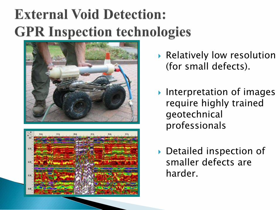
Relatively low resolution (for small defects).
Interpretation of images require highly trained geotechnical professionals
Detailed inspection of smaller defects are harder.

Pulsed radar signal Easier interpretation

Gradual deformation of plastic pipes is difficult to detect with CCTV
Need to measure cross-section dimensions and shape accurately
Need to tie measurement to accurate longitudinal or 3-D position
Conceptually simple but systematic errors possible


Recent Study Recommendations◦ NRC Report “Seeing into the Earth”◦ OPS/PHMSA Initiatives◦ Gas Technology Institute◦ UKWIR/AWWARF Initiatives
Utility Locating Improvements◦ Active technology developments◦ Technological Areas of Improvement
Utility Characterization Improvements◦ Active Technology Developments◦ Technological Areas of Improvement

Storage, Retrieval and Utilization of Utility Data Multi-Sensor Platforms /Improved Signal Coupling Development of guidelines Smart tagging Initiation of Education and Training Location of deep utilities External Soil Void Detection Technologies Bench Marking of Current Technologies Deformation Characterization Technologies
Recommendations

Report published and available for download at:http://www.trb.org/StrategicHighwayResearchProgram2SHRP2/SHRP2ResearchReports.aspx
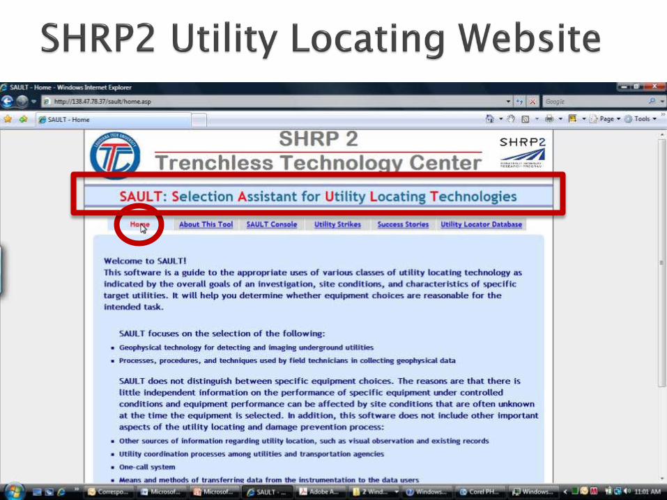
Web-based informational tools nearing completion (preliminary site tour at the end of this presentation)
Three follow-on projects underway based on the R-01 recommendations.


Focus on field technology and its application

Uses “JESS” – an expert system platform
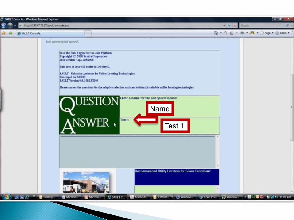
Name
Test 1

Enter “2”
Pipe

Contents
“1” Water

Metallic?
“2” Non-metallic

Conductive soil?
“2” No
History

Used before?
“2” No

Depth Range?
“2” 7 – 12 ft.
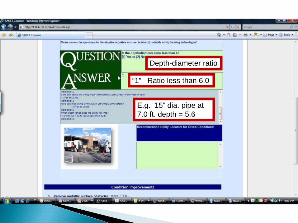
Depth-diameter ratio
“1” Ratio less than 6.0
E.g. 15” dia. pipe at 7.0 ft. depth = 5.6

Recommendation

Surface condition improvement

60 case histories currently included in database


12 cases found

One call made, water utility not marked

59 case histories currently included in database
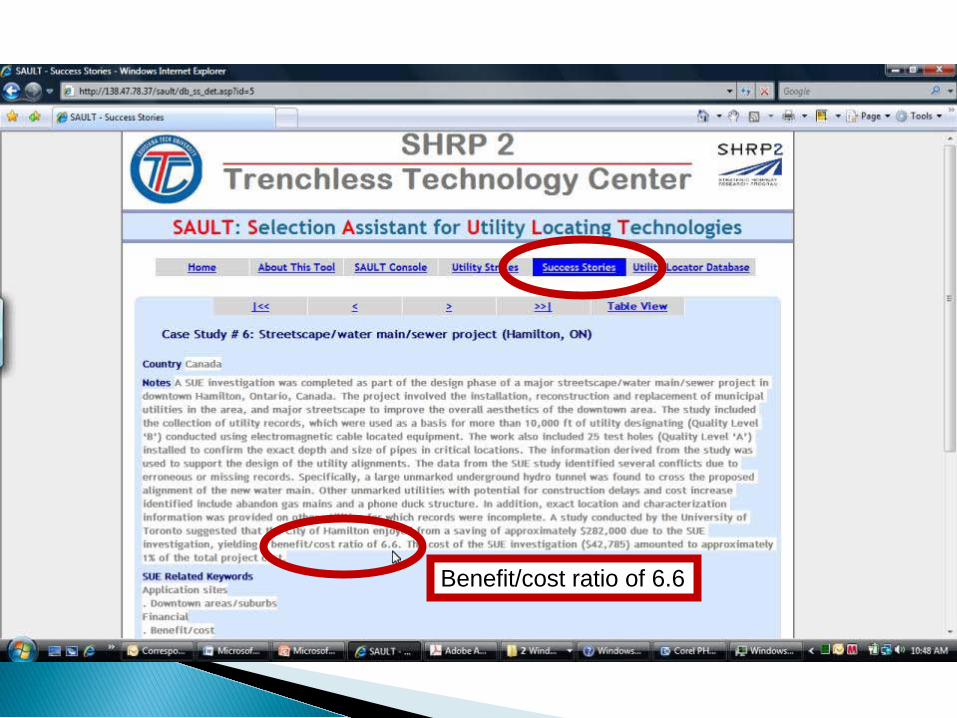
Benefit/cost ratio of 6.6
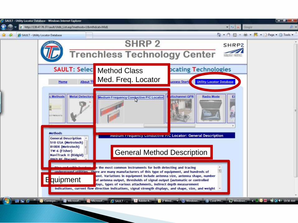
General Method Description
Equipment
Method Class Med. Freq. Locator


Ray Sterling, Professor Emeritus, Louisiana Tech [email protected] Anspach, J.H. Anspach [email protected] Allouche, TTC Research Director, Louisiana [email protected] Starnes, SHRP2 Program, [email protected]