travelling planar wave antenna for wireless...
TRANSCRIPT

3
Travelling Planar Wave Antenna for Wireless Communications
Onofrio Losito and Vincenzo Dimiccoli Itel Telecomunicazioni srl, Ruvo di Puglia (BA)
Italy
1. Introduction
Microstrip antennas are one of the most widely used types of antennas in the microwave frequency range, and they are often used in the millimeter-wave frequency range. Actually as the demand for high data rates grows and microwave frequency bands become congested, the millimeter-wave spectrum is becoming increasingly attractive for emerging wireless applications. The abundance of bandwidth and large propagation losses at millimeter-wave frequencies makes these bands best-suited for short-range or localized systems that provide broad bandwidth. Automotive radar systems including cruise control, collision avoidance and radiolocation with operation up to 10 GHz have a large market potential in the near future of millimetre wave applications.
One advantage of the microstrip antenna is easy matching, fabrication simplicity and low profile, in the sense that the substrate is fairly thin. If the substrate is thin enough, the antenna actually becomes conformal, meaning that the substrate can be bent to conform to a curved surface. Disadvantages of the microstrip antenna include the fact that it is usually narrowband, with bandwidths of a few percent being typical. Also, the radiation efficiency of the microstrip antenna tends to be lower than some other types of antennas, with efficiencies between 70% and 90% being typical. A microstrip antenna operating in a travelling wave configuration could provide the bandwidth and the efficiencies needed.
Travelling-wave antennas are a class of antennas that use a travelling wave on a guiding
structure as the main radiating mechanism. It is well known that antennas with open-ended
wires where the current must go to zero (dipoles, monopoles, etc.) can be characterized as
standing wave antennas or resonant antennas. The current on these antennas can be written
as a sum of waves traveling in opposite directions (waves which travel toward the end of
the wire and are reflected in the opposite direction). For example, the current on a dipole of
length l is given by:
(1)
www.intechopen.com

Wireless Communications and Networks – Recent Advances
48
Traveling wave antennas are characterized by matched terminations (not open circuits) so
that the current is defined in terms of waves traveling in only one direction (a complex
exponential as opposed to a sine or cosine). A traveling wave antenna can be formed by a
single wire transmission line (single wire over ground) which is terminated with a matched
load (no reflection). Typically, the length of the transmission line is several wavelengths.
Fig. 1. Beverage or wave antenna.
The antenna shown in Fig. 1 above is commonly called a Beverage or wave antenna. This
antenna can be analyzed as a rectangular loop, according to image theory. However, the
effects of an imperfect ground may be significant and can be included using the reflection
coefficient approach. The contribution to the far fields due to the vertical conductors is
typically neglected since it is small if l >> h. Note that the antenna does not radiate
efficiently if the height h is small relative to wavelength. In an alternative technique of
analyzing this antenna, the far field produced by a long isolated wire of length l can be
determined and the overall far field found using the 2 element array factor. Traveling wave
antennas are commonly formed using wire segments with different geometries. Therefore,
the antenna far field can be obtained by superposition using the far fields of the individual
segments. Thus, the radiation characteristics of a long straight segment of wire carrying a
traveling wave type of current are necessary to analyze the typical traveling wave antenna.
Traveling-wave antennas are distinguished from other antennas by the presence of a
traveling wave along the structure and by the propagation of power in a single direction.
Linear wire antennas are the dominant type of traveling-wave antennas.
There are in general two types of traveling-wave antennas [1-2]. The first one is the surface-wave antenna, which is a slow-wave structure, where the phase velocity of the wave is smaller than the velocity of light in free space and the radiation occurs from discontinuities in the structure (typically the feed and the termination regions). The propagation wavenumber of the traveling wave is therefore a real number (ignoring conductors or other losses). Because the wave radiates only at the discontinuities, the radiation pattern physically arises from two equivalent sources, one at the beginning and one at the end of the
www.intechopen.com

Travelling Planar Wave Antenna for Wireless Communications
49
structure. This makes it difficult to obtain highly-directive singlebeam radiation patterns. However, moderately directly patterns having a main beam near endfire can be achieved, although with a significant sidelobe level. For these antennas there is an optimum length depending on the desired location of the main beam. Examples include wires in free space or over a ground plane, helixes, dielectric slabs or rods, corrugated conductors, ‘‘beverage’’ antenna, or the V antenna. An independent control of the beam angle and the beam width is not possible.
The second type of the travelling wave antennas are a fast-wave structure as leaky-wave antenna (LWA) where the phase velocity of the wave is greater than the velocity of light in free space. The structure radiates all its power with the fields decaying in the direction of wave travel.
A popular and practical traveling-wave antenna is the Yagi–Uda antenna It uses an
arrangement of parasitic elements around the feed element to act as reflectors and directors
to produce an endfire beam. The elements are linear dipoles with a folded dipole used as the
feed. The mutual coupling between the standing-wave current elements in the antenna is
used to produce a traveling-wave unidirectional pattern. Recently has been developed a
new simple analytical and technical design of meanderline antenna, taped leaky wave
antenna (LWA) and taped composite right/left-handed transmission-line (CRLHTL) LWA.
The meanderline antenna is a traveling-wave structure, which enables reduction of the
antenna length. It has a periodical array structure of alternative square patterns. With this
pattern, the extended wire can be made much longer than the initial antenna (dipole) length,
so that the selfresonance can be attained. The resonance frequency is then lower and
radiation resistance is higher than that of a dipole of the same length. This in turn implies
that the antenna is effectively made small.
2. Leaky wave antennas
In detail this type of wave radiates continuously along its length, and hence the propagation
wavenumber kz is complex, consisting of both a phase and an attenuation constant. Highly-
directive beams at an arbitrary specified angle can be achieved with this type of antenna,
with a low sidelobe level. The phase constant of the wave controls the beam angle (and
this can be varied changing the frequency), while the attenuation constant controls the
beamwidth. The aperture distribution can also be easily tapered to control the sidelobe level
or beam shape.
All kinds of open planar transmission lines are predisposed to excite leaky waves. There are
two kinds of leaky waves. Surface leaky waves radiate power into the substrate. These
waves are in most cases undesirable as they increase losses, cause distortion of the
transmitted signal and cross-talk to other parts of the circuit. Space leaky waves radiate
power into a space and mostly also into the substrate. These waves can be utilized in leaky
wave antennas. Leaky-wave antennas can be divided into two important categories,
uniform and periodic, depending on the type of guiding structure. A uniform structure has
a cross section that is uniform (constant) along the length of the structure, usually in the
form of a waveguide that has been partially opened to allow radiation to occur. The guided
wave on the uniform structure is a fast wave, and thus radiates as it propagates.
www.intechopen.com

Wireless Communications and Networks – Recent Advances
50
As said previously leaky-wave antennas form part of the general class of travelling-wave antennas which are a class of antennas that use a travelling wave on a guiding structure as the main radiating mechanism [3], as defined by standard IEEE 145-1993: “An antenna that couples power in small increments per unit length, either continuously or discretely, from a travelling wave structure to free space”.
Fig. 2. Rectangular metal waveguide with a slit, aperture of the leaky wave antenna.
Leaky-wave antennas are a fast-wave travelling-wave antennas in wich the guided wave is a fast wave, meaning a wave that propagates with a phase velocity that is more than the speed of light in free space.
The slow wave travelling antenna does not fundamentally radiate by its nature, and radiation occurs only at discontinuities (typically the feed and the termination regions). The propagation wavenumber of the travelling wave is therefore a real number (ignoring conductors or other losses). Because the wave radiates only at the discontinuities, the radiation pattern physically arises from two equivalent sources, one at the beginning and one at the end of the structure. This makes it difficult to obtain highly-directive singlebeam radiation patterns. However, moderately directly patterns having a main beam near endfire can be achieved, although with a significant sidelobe level. For these antennas there is an optimum length depending on the desired location of the main beam. An independent control of the beam angle and the beam width is not possible. By contrast, the wave on a leaky-wave antenna (LWA) may be a fast wave, with a phase velocity greater than the speed of light. Leakage is caused by asymmetry, introduced in radiating structure transversal section (e.g.: aperture offset, waveguide shape, etc…), feeding modes or a combination of
them. In this type of antennas, the power flux leaking from waveguide to free space ( outP in
Fig. 2 and Fig. 3), introduces a loss inside structure, determining a complex propagation
wavenumber zk [4-5]:
( zk j ) (2)
Where is the leakage constant and is the propagation constant . The phase constant
of the wave controls the beam angle (and this can be varied changing the frequency), while the attenuation constant controls the beamwidth. Highly-directive beams at an arbitrary
specified angle can be achieved with this type of antenna, with a low sidelobe level.
www.intechopen.com

Travelling Planar Wave Antenna for Wireless Communications
51
Moreover the aperture distribution can also be easily tapered to control the sidelobe level or beam shape. Leaky-wave antennas can be divided into two important categories, uniform and periodic, depending on the type of guiding structure.
Fig. 3. Example of periodic leaky wave antenna, using a dielectric substrate upon which are placed rods of other material, even metal, in a periodic layout.
A uniform structure has a cross section that is uniform (constant) along the length of the
structure, usually in the form of a waveguide that has been partially opened to allow
radiation to occur [6]. The guided wave on the uniform structure is a fast wave, and thus
radiates as it propagates. A periodic leaky-wave antenna structure is one that consists of a
uniform structure that supports a slow (non radiating) wave that has been periodically
modulated in some fashion. Since a slow wave radiates at discontinuities, the periodic
modulations (discontinuities) cause the wave to radiate continuously along the length of the
structure. From a more sophisticated point of view, the periodic modulation creates a
guided wave that consists of an infinite number of space harmonics (Floquet modes) [7].
Although the main (n = 0) space harmonic is a slow wave, one of the space harmonics
(usually the n = −1) is designed to be a fast wave, and hence a radiating wave.
3. LWA in waveguide
A typical example of a uniform leaky-wave antenna is a rectangular waveguide with a
longitudinal slot. This simple structure illustrates the basic properties common to all
uniform leaky-wave antennas. The fundamental 10TE waveguide mode is a fast wave, with
2 20 ( )k
a
lower than 0k . As mentioned, the radiation causes the wavenumber zk of
the propagating mode within the open waveguide structure to become complex. By means
of an application of the stationary-phase principle, it can be found in fact that [5]:
0
sin mph
c
k v
(3)
www.intechopen.com

Wireless Communications and Networks – Recent Advances
52
where m is the angle of maximum radiation taken from broadside. As is typical for a
uniform LWA, the beam cannot be scanned too close to broadside ( 0m ), since this
corresponds to the cutoff frequency of the waveguide. In addition, the beam cannot be
scanned too close to endfire ( m = 90) since this requires operation at frequencies
significantly above cutoff, where higher-order modes is in a bound condition or can propagate, at least for an air-filled waveguide. Scanning is limited to the forward quadrant
only (0 < m < 2
) for a wave travelling in the positive z direction.
Fig. 4. Slotted guide (patented by W. W. Hansen in 1940).
This one-dimensional (1D) leaky-wave aperture distribution (see Fig. 4), results in a “fan beam” having a narrow beam in the x-z plane (H plane), and a broad beam in the cross-plane. Unlike the slow-wave structure, a very narrow beam can be created at any angle by choosing a sufficiently small value of . From diffraction theory, a simple formula for the
beam width, measured between half power points (3dB), is:
0
cos m
const
L
(4)
“const” is a parameter which is influenced by the type of aperture and illumination; for
example, if at the aperture there’s a constant field, const = 0.88 and, if the structure is
uniform, const =0.91. As a rule of thumb, supposing:
0
1
cos mL
(5)
a good approximation of beamwidth is yielded, where L is the length of the leaky-wave
antenna, and is expressed in radians. For 90% of the power radiated it can be assumed:
0
0
0.18L
k
www.intechopen.com

Travelling Planar Wave Antenna for Wireless Communications
53
0k
If the antenna has a constant attenuation throughout its length ( )z zz results:
2( ) (0) zP z P e
Therefore, being L the length of antenna, if a perfectly matched load is connected at the end of it, it’s possible to express antenna efficiency as:
2(0) ( ) ( )1 1
(0) (0)zL
radP P L P L
eP P
(6)
Rearranging:
ln(1 )
2rad
z
L
(7)
For most application, to gain a 90% efficiency, means that the antenna length is within
0 010 100 interval.
Fixing the antenna efficiency, using (7), makes possible to express attenuation constant in terms of antenna length, and vice versa. Using antenna efficiencies grater than 90%-95% is not advisable; in fact, supposing constant antenna cross section and, as a consequence, fixed
leakage constant, the necessary length L grows exactly as zL , which increases
asymptotically, as shown in Fig 5. If we want a 100% efficiency ( 1rad ) from (6):
2( ) 0 0zLP L e L
we note that is necessary an infinite antenna length.
Substuting (7) in (5), being 0 02 / k :
0
4
ln(1 )cosz
rad m k
Because 2cos 1 sin ,m m considering (7)
2
0
0
4
ln(1 ) 1
z
zrad
k
k
(8)
Since 2 2 20 c zk k k and having supposed the attenuation constant much smaller than the
phase constant, z zk , getting:
www.intechopen.com

Wireless Communications and Networks – Recent Advances
54
0
0
4
ln(1 )
z
crad
k kk
(9)
where ck is the transverse propagation constant. Alternatively, considering (7):
2
cL k
Using waveguide theory notation, supposing c the cut-off wavelength:
c
L
(10)
(3) and (10), provided the approximations used to be valid, are a valid tool for describing the main parameters of radiated beam.
Fig. 5. Variation of zL versus antenna efficiency.
Radiation properties of leaky wave antennas are well described by dispersion diagrams. In
fact since leakage occurs over the length of the slit in the waveguiding structure, the whole
length constitutes the antenna’s effective aperture unless the leakage rate is so great that the
power has effectively leaked away before reaching the end of the slit. A large attenuation
constant implies a short effective aperture, so that the radiated beam has a large beamwidth.
Conversely, a low value of results in a long effective aperture and a narrow beam,
provided the physical aperture is sufficiently long.
www.intechopen.com

Travelling Planar Wave Antenna for Wireless Communications
55
Moreover since power is radiated continuously along the length, the aperture field of a leakywave antenna with strictly uniform geometry has an exponential decay (usually slow), so that the sidelobe behaviour is poor. The presence of the sidelobes is essentially due to the fact that the structure is finite along z.
When we change the cross-sectional geometry of the guiding structure to modify the value
of at some point z, however, it is likely that the value of at that point is also modified
slightly. However, since must not be changed, the geometry must be further altered to
restore the value of , thereby changing somewhat as well.
In practice, this difficulty may require a two-step process. The practice is then to vary the
value of slowly along the length in a specified way while maintaining constant (that is
the angle of maximum radiation), so as to adjust the amplitude of the aperture distribution to yield the desired sidelobe performance.
Radiation modes
Let us consider a generic plane wave, whose propagation vector belongs to plane (y-z),
directed towards a dielectric film grounded on a perfect electric conductor (PEC) parallel to
plane (x-z), as shown in Fig. 6 [8-9].
Fig. 6. Incident wave on a grounded dielectric film, whose thickness is t.
If the incident wave polarization is linear and parallel to the x axis, since both reflection and refraction occur:
0 0
0
( ) ( )
cos( ) sin( )
y yjk y t jk y tx
x y y
E Ae Ce
E B k y D k y
0
y t
t y
Being the tangent components of electric field null on a PEC surface, B = 0:
0 0
0
( ) ( )
sin( )
y yjk y t jk y tx
x y
E Ae Ce
E D k y
0
y t
t y
(11)
One constant can be expressed by the remaining two, as soon as continuity of tangent components of electric field is considered in y = t. First equation of (11) contains an exponential term which, diverging for y → ∞ , violates the radiation condition at infinite
distance. Therefore, C ≠ 0 only near plane y = t , at the incidence point. zk can assume any
www.intechopen.com

Wireless Communications and Networks – Recent Advances
56
value from 0 to 0k (i.e.: radiating modes); above it, only discrete values of kz exist,
identifying the associated guided modes. Since separability condition must be satisfied, in air:
0
2 2 2 20 0 0 y zk k k where 0k (12)
For every zk , it’s now possible calculate 0yk . In fact, considering only positive solutions:
0
2 20y zk k k
Obtaining:
Mode Wave numbers
Guided 0zk k 0yk
Radiating 0 0zk k 00 0yk k
Evanescent 0 zk j 0 0yk k
Table 1. Wave modes identified by zk .
Thus, a spectral representation of electromagnetic field near the air-dielectric interface, must
contain all values of 0yk , from 0 to ∞: the associated integral is complex and slowly
convergent. Alternatively, a description, which uses leaky waves and guided modes, both
discrete, can well approximate such field.
It’s been observed that it’s often enough a single leaky wave to obtain a good far field description.
Letting 0y yk k , from (2) and (12), in general:
2 2 2 20
0
y z y z
y y z z
k
alternatively
0
222
0
k
(13)
Having defined the attenuation and the phase vectors, respectively, as:
0 0y zy z
0 0y zy z
www.intechopen.com

Travelling Planar Wave Antenna for Wireless Communications
57
Being 0k , from (9) 0 , and
Considering waves propagating in the positive direction of z axis, 0z and supposing no
losses in z direction, 0z , from (13):
0
Leaving out , 0y y , two situations can occur: 0y and 0y . If 0y , equations
describe a uniform plane wave passing the air-dielectric interface. On the other hand, if
0y , two types of superficial waves exist, depending on 0y sign:
0y
Confined superficial wave
0y
Improper superficial wave
Fig. 7. Superficial waves at air-dielectric interface when 0y .
Because confined superficial waves amplitude decreases exponentially as distance from interface increases, when y is greater than 10 times radiation wavelength, electromagnetic field practically ceases to exist. Improper superficial wave, whose amplitude increases exponentially as distance from interface increases, are not physically possible because they violate the infinite radiation condition.
Removing the hypothesis 0,z both 0,y and 0.y
Losses in Dielectric
Leaky Wave
Fig. 8. General mutual ┚ and ┙ configurations depicting condition 0 .
When losses in dielectric occur, must point towards the inner part of dielectric to
compensate such losses (see Fig.8). In the other configuration, when points upwards,
even though a non-physical solution is described, the associated wave is useful to describe
electromagnetic field near air-dielectric interface.
4. LWA in microstrip
Microstrip antenna technology has been the most rapidly developing topic in antennas during the last twenty years [10]. Microstrip is an open structure that consists of a very thin metallic strip or patch of a width, w, separated from a ground plate by a dielectric sheet
www.intechopen.com

Wireless Communications and Networks – Recent Advances
58
called substrate (Fig. 9). The thickness of the conductor, t, is much less than a wavelength, and may be of various shapes. The height of the substrate, h, is usually very thin compared
to the wavelength (.0003 ≤ h ≤ 0.05 ) [11]. The substrate is designed to have a known
relative permittivity, r , that is homogeneous within specified temperature limits.
Fig. 9. Geometry of a microstrip transmission line.
The antenna can be excited directly by a microstrip line, by a coaxial cable, or a combination
of the two. The antenna can also be fed from a microstrip line without direct contact through
electromagnetic coupling. Feeding by electromagnetic coupling through an aperture in the
ground plane tends to improve bandwidth. To maximize efficiency, the impedance of the
feed must be matched to the input impedance of the antenna. There are a variety of stubs,
shunts, and other devices used for matching. The major disadvantages of microstrip are
lower gain, very narrow bandwidth, low efficiency and low power handling ability. In
addition, antennas made with microstrip typically have poor polarization purity and poor
scan performance [12].
Operating above the cutoff frequency, the field lines of microstrip extend throughout the
substrate as well as into the free space region above the substrate, as seen in Fig. 10. The
phase velocity of the field in the free space surrounding the structure is the speed of light, c,
and the phase velocity of the field in the substrate is given by Equation (14)
pr
cv (14)
This difference in phase velocity at the interface between the substrate and free space makes
the TEM mode impossible. Instead, the fundamental mode for microstrip is a quasi-TEM
mode, in which both the electric and magnetic fields have a component in the direction of
propagation. Likewise, a higher order mode in microstrip is not purely TE or TM, but a
hybrid combination of the two. The nth higher order mode is termed the nTE mode. The
fundamental mode of microstrip, as seen in Fig. 10, does not radiate since the fields
produced do not decouple from the structure. If the fundamental mode is not allowed to
propagate, the next higher order mode will dominate. Fig. 11 shows the fields due to the
first higher order mode, 10TE . A phase reversal, or null, appears along the centerline,
allowing the fields to decouple and radiate.
www.intechopen.com

Travelling Planar Wave Antenna for Wireless Communications
59
Fig. 10. Field pattern associated with the fundamental mode of microstrip.
Fig. 11. Field pattern associated with the first higher order mode of microstrip.
Recently, there has been significant interest in the microstrip leaky-wave antenna which
utilizes a higher order radiative microstrip mode. Since Menzel in 1979, published the first
account of a travelling wave microstrip antenna that used a higher order mode to produce
leaky waves [13], many microstrip leaky-wave antenna designs incorporating various
modifications have been investigated. The design of Menzel antenna [13], can be seen in Fig.
12. Menzel’s antenna uses seven slots cut from the conductor along the centerline to
suppress the fundamental mode allowing leaky wave radiation via the first higher order
mode. Menzel’s antenna has been analyzed by a host of researchers over the past 25 years
[14] and its performance is known and reproducible. Instead of transverse slots, we can uses
a metal wall down the centerline of the antenna to block the fundamental mode. Symmetry
along this metal wall invites the application of image theory. One entire side of the antenna
Fig. 12. Menzel’s original antenna [13].
www.intechopen.com
Wireless Communications and Networks – Recent Advances
60
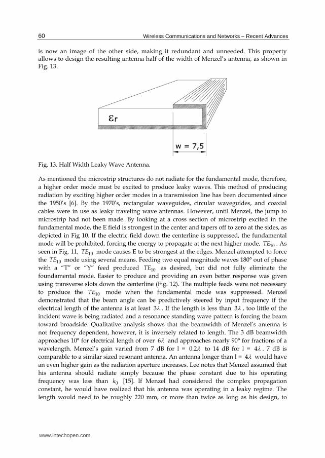
is now an image of the other side, making it redundant and unneeded. This property allows to design the resulting antenna half of the width of Menzel’s antenna, as shown in Fig. 13.
Fig. 13. Half Width Leaky Wave Antenna.
As mentioned the microstrip structures do not radiate for the fundamental mode, therefore,
a higher order mode must be excited to produce leaky waves. This method of producing
radiation by exciting higher order modes in a transmission line has been documented since
the 1950’s [6]. By the 1970’s, rectangular waveguides, circular waveguides, and coaxial
cables were in use as leaky traveling wave antennas. However, until Menzel, the jump to
microstrip had not been made. By looking at a cross section of microstrip excited in the
fundamental mode, the E field is strongest in the center and tapers off to zero at the sides, as
depicted in Fig 10. If the electric field down the centerline is suppressed, the fundamental
mode will be prohibited, forcing the energy to propagate at the next higher mode, 10TE . As
seen in Fig. 11, 10TE mode causes E to be strongest at the edges. Menzel attempted to force
the 10TE mode using several means. Feeding two equal magnitude waves 180° out of phase
with a “T” or “Y” feed produced 10TE as desired, but did not fully eliminate the
foundamental mode. Easier to produce and providing an even better response was given
using transverse slots down the centerline (Fig. 12). The multiple feeds were not necessary
to produce the 10TE mode when the fundamental mode was suppressed. Menzel
demonstrated that the beam angle can be predictively steered by input frequency if the
electrical length of the antenna is at least 3 . If the length is less than 3 , too little of the
incident wave is being radiated and a resonance standing wave pattern is forcing the beam
toward broadside. Qualitative analysis shows that the beamwidth of Menzel’s antenna is
not frequency dependent, however, it is inversely related to length. The 3 dB beamwidth
approaches 10° for electrical length of over 6 and approaches nearly 90° for fractions of a
wavelength. Menzel’s gain varied from 7 dB for l = 0.2 to 14 dB for l = 4 . 7 dB is
comparable to a similar sized resonant antenna. An antenna longer than l = 4 would have
an even higher gain as the radiation aperture increases. Lee notes that Menzel assumed that
his antenna should radiate simply because the phase constant due to his operating
frequency was less than 0k [15]. If Menzel had considered the complex propagation
constant, he would have realized that his antenna was operating in a leaky regime. The
length would need to be roughly 220 mm, or more than twice as long as his design, to
www.intechopen.com

Travelling Planar Wave Antenna for Wireless Communications
61
radiate at 90% efficiency. Radiation patterns in Menzel’s paper clearly show the presence of
a large backlobe due to the reflected traveling wave.
Now this class of printed antennas that is particularly well suited for operation at mm-wave frequencies, alleviate some of the problems associated with resonant antennas since they provide higher gain, broader bandwith performance, and frequency scanning capabilities. These microwave and millimeter leaky wave antennas, have the same properties of the waveguide leaky wave antennas described previously. In addition, when opening a waveguide to free space, a discrete spectrum is not enough to express an arbitrary solution [16].
In fact, when considering a closed region, all characteristic solutions, individuated by the associated eigenvalues, constitute a complete and orthogonal set of modes, whose linear combination can express any field satisfying boundary conditions. As soon as the region is not perfectly bounded, an arbitrary field solution cannot be expressed only using discrete eigenmodes but, generally, a continuous spectrum of modes, which don’t necessarily have finite energy (e.g.: plane waves), must be considered, too.
Fortunately, for leaky wave antennas, an approximation that uses particular waves, called leaky, can be used instead of the continuous spectrum. Moreover, leaky waves are well described by dispersion constants (i.e.: leakage and phase constants) that strongly affect the radiated beam width and elevation.
5. Dispersion curves, spectral-gap
Dispersion curves, describing how attenuation and phase vectors, solutions of dispersion equation (12), evolve, are a valid tool to study leaky waves.
As discussed previously, the radiation mechanism of higher order modes on microstrip
LWA is attributed to a traveling wave instead of the standing wave as in patch antennas and
above cutoff frequency, where the phase constant equals the attenuation constant ( c = c ),
it is possible to observe three different range of propagation: bound wave, surface wave and
leaky wave [15]. At low frequency, below the cutoff frequency, we have the reactive region
due to evanescent property of LWA.
From (3) we can observe that the leaky mode leaks away in the form of space wave when
0K , therefore we can define the radiation leaky region from the cutoff frequency to the
frequency at which the phase constant equals the free-space wavenumber 0( )K . For
( )sK we have the bound mode region and for 0 sK K , exists a narrow frequency
range (1
sr
K ), in which we can have surface-wave leakage, where sK is the surface
wavenumber.
Moreover the transition region between surface wave leakage and space wave leakage including a small range in frequency for which the solution is non-physical, and it therefore cannot be seen. For this reason, the transition region is called a spectral gap. Such a spectral gap occurs commonly (but not always) at such transitions in printed circuits, but it also occurs in almost all situations for which there is a change from a bound mode to a leaky
www.intechopen.com

Wireless Communications and Networks – Recent Advances
62
Fig. 14. The typical normalized attenuation constant, 0/ k , and phase constant 0/ k , in
the direction of propagation of the first higher order mode, 10TE . There are four frequency
regions associated with propagation regimes: Reactive, Leaky, Surface, and Bound.
mode, or vice versa. For example, a spectral gap will appear when the beam approaches
endfire in all leaky-wave antennas whose cross section is partly loaded with dielectric
material. It is necessary to employ a greatly enlarged scale, on which the dispersion plot is
sketched qualitatively. The transition region itself is divided into two distinct frequency
ranges, one from point A to point B and the second from point B to point C. Before point B, a
leaky wave occurs. As soon as frequency reaches 1f (point B), an improper superficial wave
is solution of dispersion equation [9]. Because, both z and z cannot increase with
frequency between 1f and 2f , their trend will change until point C, from which a confined
superficial wave is an acceptable solution for increasing values of frequency.
To depict normalized constants behaviour around the spectral-gap, it’s necessary a very
precise numerical method since, leaving out particular structures, its width ( f ) is very
small compared to working frequencies.
The dispersion characteristics for microstrip has been investigated by a number of authors
using different full wave methods and evaluating different regimes of the dispersion
characteristic.
The spectral domain analysis has proven to be one of the most efficient and fruitful
techniques to study the dispersion characteristics of printed circuit lines [17]. As is explained
in literature, the Galerkin method in conjunction with Parseval theorem can be used to pose
the dispersion relation of an infinite printed circuit line as the zeros of the following
equation:
www.intechopen.com

Travelling Planar Wave Antenna for Wireless Communications
63
2;( ) ( ) ( ) 0
x
z zz x z x x
C
F k G k k T k dk (15)
where ( )xT k , is the Fourier transform of the basis function ( )xT k used to expand the
longitudinal current density on the strip conductor as
( , ) ( ) zjk zszJ x z T x e
The term ; ,( )zz x zG k k is the zz component of the spectral dyadic Green’s function, and xC is
an appropriate integration path in the complex xk plane to allow for an inverse Fourier
transform non uniformly convergent function. The spectral dyadic Green’s function has the
following singularities in the complex xk plane: branch point, a finite set of poles on the
proper sheet and a infinite set of poles on the improper sheet. For a fixed frequency, the
function ( )zF k is not uniquely defined because of the many possible different xC integration
paths that can be used to carry out the integral (15) [18].
Fig. 15. Transition region between leaky wave and confined superficial wave showing the
spectral-gap occurring 1f and 2f .
The different xC paths come from the different singularities of the spectral dyadic Green’s
function, that can be detoured around. For complex leaky mode solution, an integration
path detouring around only the proper poles of the spectral dyadic Green’s function is
associated with an surface-wave leaky mode solution. If the path also detours around the
branch points, passing trough the branch cuts and, therefore, lying partly on the lower
Riemann sheet, the path will be associated with an space-wave leaky mode solution (see Fig.
16). This procedure, is not trivial. We shown in the next chapters how it is possible to extract
the propagation constant of a microstrip LWA more simply using an FDTD code with
UPML boundary condition, who directly solves the _elds in the time domain using
Maxwell's equations and with which the analysis is easy modifying the geometries of the
LWAs. The results are in a good agreement with transverse resonance approximation (a full
wave method) derived by Kuestner [19].
www.intechopen.com

Wireless Communications and Networks – Recent Advances
64
Fig. 16. Possible integration paths C . The three different are denoted as 0C for the real-axis
path (bound mode solution), 1C for the path that detours around only the spectral dyadic
Green’s function poles (surface-wave leaky modes solution), and 2C for the path that also
passes around the branch points (space-wave leaky modes solution).
6. Tapered leaky wave antennas
Nowdays, some applications especially with regard to communication applications like the indoor wireless LAN(WLAN) actually are increasing the use of millimeterwave antennas like leaky-wave antennas (LWA), suited for more purpose. In detail, the transmitting/ receiving antennas with relatively broadbeam and broadband can be obtained from the curved and tapered leakywave structures. In fact, the microstrips (LWA), are very popular and widely used in applications thanks to their advantages of low-profile, easy matching, narrow beamwidth, fabrication simplicity, and frequency/electrical scanning capability. Is well know that the radiation mechanism of the higher order mode on microstrip LWAs is attributed to a traveling wave instead of the standing wave as in patch antennas. Moreover the symmetry of the structure along this physical grounding structure, thanks to the image theory, allows to design only half of an antenna with the same property of one in its entirety, and reducing up to 60% the antenna’s dimensions. Using this tapered antenna we can obtained a quasi linear variations of the phase normalized constant and than a quasi linear variations of the its radiation angle. Moreover the profile of the longitudinal edges of the LWA, was designed, by means of the reciprocal slope of the cutoff curve, symmetrically to the centerline of the antenna, allows a liner started of leaky region.
Nevertheless the variation of the cross section of the antenna, allowing a non-parallel emitted rays, such as happens in a non-tapered LWA. In fact, using the alternative geometrical optics approach proposed in the tapering of the LWA, for a fixed frequency, involves the variation of the phase constant ┚ and the attenuation constant ┙, obtained as a cut plane of 3D dispersion surface plot varying width and frequency. We can be determined a corresponding beam radiation interval with respect to endfire direction. As mentioned previously, for a tapered antenna with a curve profile (square root law profile) the radiation angle in the leaky regions, vary quasi linearly whit the longitudinal dimension, so it is possible to calculate the radiation angle of the antenna as a average of the phase constant using the simple formula.
www.intechopen.com

Travelling Planar Wave Antenna for Wireless Communications
65
Alternatively using the geometrical optics approach it is easy to determine the closed formula to predict the angle of main beam of a tapered LWA.
7. Design of tapered LWA
The radiation mechanism of the higher order mode on microstrip LWAs is attributed to a traveling wave instead of the standing wave as in patch antennas [13,20].
We can explain the character of microstrip LWAs trough the complex propagation constant
k j , where is the phase constant of the first higher mode, and is the leakage
constant. Above the cutoff frequency, where the phase constant equals the attenuation
constant ( c = c ), it is possible to observe three different propagation regions: bound wave,
surface wave and leaky wave.
The main-beam radiation angle of LWA can be approximated by:
1
0
cosK
(16)
where is the angle measured from the endfire direction and 0K is the free space
wavenumber. According to (16) we can observe that the leaky mode leaks away in the form
of space wave when 0K , therefore we can define the radiation leaky region, from the
cutoff frequency to the frequency at which the phase constant equals the free-space
wavenumber 0( )K . An example of tapered LWA was proposed in [21-22], using an
appropriate curve design to taper LWA.
In fact through the dispersion characteristic equation, evaluated with FDTD code, we can obtain the radiation region of the leaky waves indicated in the more useful way for the design of our antenna:
2 1
c rc
eff r r
fcf f
w
. (17)
From equation (17) we can observe that the cutoff frequency increases when the width of the
antenna decrease, shift toward high frequencies, the beginning of the radiation region as
shown in Fig. 17. 1.
Therefore it is possible to design a multisection microstrip antenna [as Type I antenna in Fig.
17.a], in which each section able to radiate at a desired frequency range, can be
superimposed, obtaining an antenna with the bandwidth more than an uniform microstrip
antenna. In this way every infinitesimal section of the multisection LWA obtained
overlapping different section should be into bound region, radiation region or reactive
region, permitting the power, to uniformly radiated at different frequencies.
Using the same start width and substrate of Menzel travelling microstrip antenna (TMA)
[13], and total length of 120 mm., we have started the iterative procedure mentioned in [23]
to obtain the number, the width and the length of each microstrip section. From Menzel
www.intechopen.com

Wireless Communications and Networks – Recent Advances
66
TMA width, we have calculated the STARTf (onset cutoff frequency) of the curve tapered
LWA, than, choosing the survival power ratio ( 2 i iLe ) opportunely, at the end of the
first section, we have obtained the length of this section. The cutoff frequency of subsequent
section ( if ), was determined by FDTD code, while the length of this section was
determined, repeating the process described previously. This iterative procedure was
repeated, until the upper cutoff frequency of the last microstrip section.
0
10
20
30
40
50
60
70
80
5,94 6,85 8,03 9,51 11,52
Frequency [Ghz]
[rad
/m]
Fig. 17.1 Cutoff frequency of multisection microstrip LWA.
The presence of ripples in return loss curve and the presence of spurious sidelobes shows
the impedence mismatch and discontinuity effect of this multisection LWA that reduce the
bandwidth. A simple way to reducing these effects is to design a tapered antenna in which
the begin and the end respectively of the first and the last sections are linearly connected
together (as the Type II antenna in Fig. 17.a).
Alternatively the ours idea was to design a LWA using a physical grounding structure along
the length of the antenna, with the same contour of the cutoff phase constant or attenuation
constant curve ( c = c ), obtained varying the frequency (the cutoff frequency fc is the
frequency at which c = c ) , for different width and length of each microstrip section as
shown in Fig. 17.1, employing the following simple equation (18):
21 2 3c c f c f c (18)
obtained from linear polynomials interpolation, where 1c = 0.0016, 2c = 0.03, 3c = -15.56.
The antenna layout (as the Type III antenna in Fig. 17.a), was optimized through an 3D
electromagnetic simulator, and the return loss and the radiation pattern was compared with
Type I antenna and Type II antenna.
www.intechopen.com

Travelling Planar Wave Antenna for Wireless Communications
67
8. Simulation results
An asymmetrical planar 50 Ω feeding line was used to excite the first higher-order mode while a metal wall down the centerline connecting the conductor strip and the ground plate was used to suppress the dominant mode for Type I - III. The chosen substrate had a dielectric constant of 2.32 and a thickness of 0.787 mm, while the total length of the leaky wave antenna was chosen to be 120 mm.
The leaky multisection tapered antenna Type I was open-circuited, with a 15 mm start width, and 8.9 mm of final width obtained according to [23]. For LWA layout Type I, we used four microstrip steps, for layout Type II we tapered the steps linearly, while the curve contour of the LWA layout Type III, was designed through equation (18).
Fig. 17.b shows the simulated return loss of three layouts. We can see that the return loss (S11) of Type I is below -5 dB from 6 to 10.3 GHz, but only three short-range frequencies are below -10 dB. S11 of Type II is below -5 dB from 6.1 to 9.1 GHz, and below -10 dB from 6.8 to 8.6 GHz. At last, S11 of Type III is below -5 dB from 6.8 to 11.8 GHz, and below -10 dB from 8.0 to 11.2 GHz. In Fig.17.c are shows the mainlobe direction at 9.5 GHz for the different Type I to Type III. We can see a reduction of sidelobe and only few degrees of mainlobe variation between Type I to Type III. Moreover, in Fig. 18 is shown the variation of mainlobe of antenna Type III, for different frequency, while in Fig. 19 is shown the trend of gain versus frequency of the same antenna. It is clear that, the peak power gain is more than 12 dBi, which is almost 3 dBi higher than uniform LWAs.
Finally the simulated VSWR is less than 2 between 8.01 and 11.17 GHz (33%), yielding an interesting relative bandwidth of 1.39:1, as shown in Fig. 20, compared with uniform microstrip LWAs (20% for VSWR < 2) as mentioned in [24].
Fig. 17a. Layout of leaky wave antennas Type I-III. A physical grounding structure was used to connecting the conductor strip and the ground plane.
Type I
Type II
Type III
www.intechopen.com

Wireless Communications and Networks – Recent Advances
68
Fig. 17b. Simulated Return loss of Type I-III LWA.
These results indicate a high performance of Type III LWA: high efficiency excitation of the
leaky mode, increases of the bandwidth, improves the return loss and reduction of 19% of
metallic surface with respect to uniform LWA. Moreover, these results are in a good
agreement whit the experimental results of return loss and radiation pattern of a prototype
made using a RT/Duroid 5880 substrate with thickness of 0.787 mm and relative dielectric
constant of 2.32, as shown in Fig.21 and Fig.22.
www.intechopen.com

Travelling Planar Wave Antenna for Wireless Communications
69
Fig. 17c. Radiation patterns of Electric field (H plane) of Type I-III, LWA at 9.5 GHZ.
a)
Fig. 18. a) Simulated radiation patterns of E field of LWA Type III for different frequency. b) 3-D radiation pattern of Electric field.
0
2
4
6
8
10
12
14
6 6,7 7,2 8 8,2 9 9,5 10,5
Frequency [GHz]
Gai
n [d
Bi]
Gain LWA Type III\
Fig. 19. The gain versus frequency of the LWA Type III.
www.intechopen.com

Wireless Communications and Networks – Recent Advances
70
Fig. 20. Simulated VSWR of LWA Type III.
Fig. 21. A prototype of tapered LWA Type III with holes made in the centerline of the antenna.
a) b)
Fig. 22. a) Measurement set-up of LWA Type III. b) Experimental and simulated return loss of LWA Type III.
www.intechopen.com

Travelling Planar Wave Antenna for Wireless Communications
71
Fig. 23. A prototype of half tapered LWA.
Moreover the use of a physical grounding structure along the length of the antenna, as suggested in [21-22], allows the suppression of the dominant mode (the bound mode), the adoption of a simple feeding, and due to the image theory, it is also possible to design only half LWA (see Fig. 23) with the same property of one entire, as shown in Fig. 24 and in Fig. 25, reducing up to 60% the antenna’s dimensions compared to uniform LWAs [24].
Fig. 24. Measured return loss of full and half Leaky Wave Antennas
Fig. 25. The measured and simulated radiation patterns of E field of half tapered LWA at 8 GHz.
www.intechopen.com

Wireless Communications and Networks – Recent Advances
72
9. Focusing-diverging property
As described in [21-22], the profile of the longitudinal edges of the LWA, was designed, by
means of the reciprocal slope of the cutoff curve, symmetrically to the centerline of the antenna,
allows a liner started of leaky region. Using this tapered antenna we can obtained a quasi linear
variations of the phase normalized constant and than a quasi linear variations of the its
radiation angle as we can see in Fig. 26 and in Fig. 27. Nevertheless the variation of the cross
section of the antenna, allowing a non-parallel emitted rays, such as happens in a non-tapered
LWA (see Fig. 28). In fact, as was described in the alternative geometrical optics approach
proposed in [24] the tapering of the LWA, for a fixed frequency, involves the variation of the
phase constant and the attenuation constant , as shown in Fig. 29, obtained as a cut plane
of 3D dispersion surface plot varying width and frequency (see Fig. 30).
Fig. 26. The variation of the main beam radiation angle versus length of the antenna, at f= 8 GHz, for linear, square and square root profile of the LWA.
Fig. 27. The variation of the phase constant versus length of the antenna, at f= 8 GHz, for linear, square and square root profile of the LWA.
www.intechopen.com

Travelling Planar Wave Antenna for Wireless Communications
73
From (16) can be determined in the leaky regions of the antenna, a corresponding beam
radiation interval [ min, max
], , with respect to endfire direction.
As mentioned previously, for a tapered antenna with a curve profile (square root law
profile) the radiation angle in the leaky regions, vary quasi linearly whit the longitudinal
dimension, so it is possible to calculate the radiation angle of the antenna as a average of the
phase constant using the simple equation (19).
1
00
1( )
L
m sen z dzK L
(19)
Alternatively using the geometrical optics it is easy to determine the closed formula to predict the angle of main beam of a tapered LWA. Through simple mathematical passages,
the main beam angle m can be obtained by the equation (20).
1 min
2 2min max
1(2 ) ( 2 cos )
2
mAsen
sen
Asen L C
(20)
Where A and C are respectively the distance between real focus F and the beginning and
the end of the length of the antenna L . Therefore, if we know the begin width and the end
width of the antenna, from the curves of normalized phase and attenuation constant at fixed
frequency, we can determine the beam radiation range from (16), and the main beam angle
through (20).
Fig. 28. The ray optical model for a tapered Leaky Wave antenna.
Furthermore this focusing phenomena of a tapered LWA can determine a wide-beam pattern in a beam radiation range which is evident when the antenna length is increased
( 050L ) [25].
www.intechopen.com

Wireless Communications and Networks – Recent Advances
74
Fig. 29. The curve of normalized phase and attenuation constants versus the width, at 8 GHz for the LWA with the angular range [28°, 76°]. The leaky region start from 10.8 mm. (cutoff frequency).
To obtain a broad beam pattern without the use of a longer LWA, we can bend a tapered
LWA (see Fig. 31), leading the electromagnetic waves to diverge. This, increases the beam of
the radiation pattern and reduce furthermore the back lobes as we can see compared the
curves of Fig. 32. Finally in Fig. 33 is shown the measured return loss of half bend LWA
Type III.
Fig. 30. The 3D normalized phase constant and attenuation constant of tapered LWA versus frequency and width.
www.intechopen.com

Travelling Planar Wave Antenna for Wireless Communications
75
a)
b)
Fig. 31. a)Layout of a bend tapered LWA. b) A prototype of bend half LWA Type III made
using Roger 5880 RT/Duroid.
a) b)
Fig. 32. a)The radiation patterns of E field of tapered LWA at f= 8 GHz. b) The radiation
patterns of E field of bend tapered LWA at f= 8 GHz.
www.intechopen.com

Wireless Communications and Networks – Recent Advances
76
Fig. 33. Experimental return loss of half bend LWA Type III.
10. Tapered composite right/left-hande d transmission-line (CRLH-TL) leaky-wave antennas (LWAs)
Recently composite right/left-handed (CRLH) leaky-wave antennas (LWAs) have been
shown as one of the applications of the CRLH transmission line (TL) metamaterials thanks
to their advantages of fabrication simplicity and frequency/electrically scanning capability
without any complex feeding network. Neverthless the fixed geometrical size of a unit cell
of the CRLH-TL Leaky-wave antennas, prevents the possibility to improve the antenna
bandwidth “tapering” the geometrical size of unit cell.
It is well known as a composite right/left-handed transmission-line (CRLH-TL) metamaterials, used for the leaky-wave antennas (LWAs) allow to obtain a superior frequency scanning ability than its conventional counterpart [26-27]. The leaky-wave antennas possess the advantages of low-profile, easy matching, fabrication simplicity, and frequency/electrically scanning capability without any complex feeding network.
However, the conventional leaky-wave antennas suffer from major limitations in their
scanning capabilities. In fact the radiation pattern is restricted to strictly positive for
uniform configurations, or to a discontinuous range of negative or positive excluding
broadside direction, for periodic configurations. The CRLH LWAs have essentially
suppressed these limitations, being able to scans the entire space from = -90° to = +90°
and thereby paved the way for novel perspectives for leaky-wave antennas.
Although actually the designs of CRLH-TL for LWAs available in the literature, are developed as a different number of unit cell with a fixed geometrical size for all the unit cells of the entire antenna.
These design prevents the possibility to improve the antenna bandwidth “tapering” the geometrical size of unit cell. In order to obtain an improvement of the antenna bandwidth a novel design of CRLH LWAs was used in our work. The simulation results of the the CRLH
www.intechopen.com

Travelling Planar Wave Antenna for Wireless Communications
77
unit-cell with different size, obtained by a commercial 3D EM simulator has shown the good performance of this antenna compared with the performance of the uniform CRLH TL LWA antenna.
The good performance of this composite right/left-handed LWA are also demonstrated by measured results, which shown a good agreement with simulation results paving the way for the future applications of the antenna.
11. Antenna design
It has been shown that the leakage rate of the CRLH-TL LWA can be altered by using different sizes of the unit-cell [27] as shown in Fig.34.
Fig. 34. Different size and number of fingers of CRLH-TL unit cell.
In detail the radiation resistance, of the unit-cell having four fingers and the unit-cell of six
fingers, both the unit-cells designed to have the phase origin at the same frequency, shows
two different bandwidth as mentioned in [27-28].
The radiation resistance of the four finger antenna is always higher than that of the six-
finger one, which implies faster decay of power (more leakage) along the structure for the
former.
Moreover it should be noted that increasing the number of fingers the size of the unit-cell
has to be reduced in order to have the same centre-frequency for the antenna antennas,
otherwise, the centre-frequency for the antenna with unit-cell which have the larger number
of fingers will shift down to a lower frequency [29-30].
As shown in [21-22] for a simple microstrip leaky wave antenna the radiation bandwidth is
governed by the line width once the substrate is fixed. The bandwidth can be improved by
adopting a tapered line structure (Fig.35), where, the radiation of different frequency
regions leaks from different parts of the antenna.
Fig. 35. A taper layout of LWA with a different frequency regions leaks from different parts of the antenna.
www.intechopen.com

Wireless Communications and Networks – Recent Advances
78
In fact from the propagation characteristics of the leaky wave antenna, we known that the
leakage radiate phenomena, can only be noted above the cutoff frequency of higher order
mode, and below the frequency such that, the phase constant is equal at the free space wave
number. Decreasing the width of the antenna for a microstrip leaky-wave antenna the cutoff
frequency increases shift toward high frequency. This behaviour allows to design a
multisection microstrip LWA according [21-22] superimposing different section, in which
each section can radiate in a different and subsequence frequency range, obtaining a
broadband antennas. In this way each section should be into bound region, radiation region
or reactive region, permitting the power, to uniformly radiated at different frequencies.
Following these idea in the our developed procedure we have applied a process to get the
dimension of the physical parameters of the unit cell shows in Fig. 36 whit different
optimized number of fingers (see Fig. 37). Naturally we have calculated the extraction
parameters of every cell of CRLH implementation: LR, CR, LL, and CL using the equation
mentioned in [26].
In the case of CRLH transmission line based LWA the amount of radiation by the unit cell
can be related to the beam shape required and thus can be used to determine the total size of
the structure as mentioned in [31].
Fig. 36. Unit cell equivalent circuit with radiation resistance.
Given the unit cell equivalent circuit in Fig. 36, we have the per unit length series impedance and per unit length shunt admittance as follows [31]:
' ' ' ''a l RL
jZ R R j L
C (21)
' ' ' ''l RL
jY G R j C
L (22)
Where 'aR represents radiation resistance per unit length, '
lR represents the per unit length
resistance associated with transmission loss, 'RL and '
RC denotes per unit length parasitic
inductance and capacitance respectively, 'LC and '
LL denotes times unit cell length left-hand
capacitance and inductance respectively.
Propagation constant and characteristics impedance are given by the following relations:
www.intechopen.com

Travelling Planar Wave Antenna for Wireless Communications
79
' 'j ZY (23)
'
'cZ
ZY
(24)
From the above expression of propagation constant and line impedance we can find the centre frequency of the CRLH LWA [31].
These procedure was applied for subsequency frequency range of interest able to obtain a broadband antenna and a narrow-beam radiation pattern more than the uniform CRLH-TL LWA.
Fig. 37. Layout of a single unit cell of CRLH-TL LWA were p is the length of the unit cell period, lc, is the length of the capacitor w and ws represent, the overall width of its finger and the width of the stub respectively.
The optimized antenna design as we can see in Fig. 38 was obtained considering the
sequence of 16 cells composed respectively by 4 cell with 12 fingers, 4 cells with 10 fingers,
Fig. 38. Layout of the 16 unit-cell CRLH-TL LWA with cells of 10, 8 and 6 fingers.
www.intechopen.com

Wireless Communications and Networks – Recent Advances
80
4 cell with 8 fingers and 4 cell with 6 fingers for the entire length of the antenna of 207.55 mm and width between 2.9 mm (cells with 12 fingers) and 5.9 mm (cells with 6 fingers).
12. Simulation and experimental results
In the following Fig. 39 and Fig. 40 are showing the simulation data of the return loss
obtained with a 3D EM commercial software, of the uniform 16 unit-cell CRLH-TL LWA of
10 fingers compared with the results of tapered 16 unit-cell CRLH-TL LWA. Instead in Fig.
41 and in Fig. 42, are shown the results of the radiation pattern of the uniform CRLH-TL
LWA compared with 16 unit-cell of 10 fingers and tapered 16 unit-cell CRLH-TL LWA. It is
evident the good performance of the tapered 16 unit-cell CRLH-TL LWA compared with
uniform CRLH-TL LWA in term of broadband and narrowbeam.
Fig. 39. Return loss (S11) of the uniform 16 unit-cell CRLH-TL LWA with 10 fingers.
Fig. 40. Return loss (S11) of the 16 unit-cell CRLH-TL LWA with cells of 12, 10, 8 and 6
fingers.
www.intechopen.com

Travelling Planar Wave Antenna for Wireless Communications
81
Fig. 41. Radiation pattern of the E field of the uniform CRLH-TL LWA for f=1.12 GHz (red line), f=2.30 GHz (brown line), f= 3.20 GHz (blu line).
Fig. 42. Radiation pattern of the E field of the tapered CRLH-TL LWA for f=1.12 GHz (red line), f=2.30 GHz (brown line), f= 3.20 GHz (blu line).
The simulation results were compared with experimental results made on a prototype of
CRLH-TL LWA (see Fig. 43) designed with 16 unit-cell on Rogers RT/duroid 5880 substrate
with dielectric constant εr = 2.2 and thickness h = 62 mil (loss tangent = 0.0009) showing a
quite good agreement with simulated results of tapered 16 unit-cell CRLH-TL LWA as we
can see in Fig. 44 and Fig. 45.
www.intechopen.com

Wireless Communications and Networks – Recent Advances
82
Fig. 43. A prototype and its detail of Radiation patter of tapered 16 unit-cell CRLH-TL LWA made on Rogers RT/duroid 5880.
Fig. 44. Experimental return loss (S11) of the 16 unit-cell prototype CRLH-TL LWA with cells of 12, 10, 8 and 6 fingers.
Fig. 45. Experimental E field radiation pattern of tapered prototype CRLH-TL LWA for f=1.12 GHz (red line), f=2.30 GHz (brown line), f= 3.20 GHz (blu line).
13. Meander antenna
Nowadays, miniaturization of electronic devices is the main request that productions have to fulfil. In this process, the reduction of the antenna size is the crucial challenge to face, being its dimensions related to the working frequency.
The rapid developing of the modern society has become to a crescent interest for the wireless communications. Nowadays, everybody wants to be connected everywhere
www.intechopen.com

Travelling Planar Wave Antenna for Wireless Communications
83
without the use of cumbersome devices. The current tendency goes towards portable terminals that have to be light and hand pocket. A suitable antenna for the portable terminals should be low cost, low profile, light weight and especially small size.
Printed antennas are commonly used for their simple structure and easy fabrication. As applications are space limited, it is challenging to design an antenna of small size but with simple tunable feature. For microstrip antennas, some techniques, such as making slots in their structure or using high dielectric constant substrates, can be used to reduce the antenna size. However, it results in the narrow bandwidths for its high Q factor and the low radiation efficiency.
In the following sentences is described an antenna printed on a substrate with low dielectric constant in order to get a reliable bandwidth. Moreover, the meander configuration allows us to reduce the antenna size keeping good radiation performance.
Meander dipole antennas have been already designed through numerical techniques that apply either time- or frequency-domain algorithms demanding high computational efforts and long-time processing. The common approach in the design of meander antenna is to draw a meander path with a suited length to the working frequency in commercial software and run simulations. Nevertheless, This empirical approach may lead to several consecutive trials and verifications. In order to decrease the long-time processing and avoid these cut and try methods, it would be convenient to start simulations with a commercial software having an antenna size close to its optimized dimensions. Thus, a good initial configuration can strongly affect the numerical convergence efficiency and the design process would be quicker.
This paper presents a transmission line model that provides an initial geometrical configuration of the antenna that allows us a computational improvement in the design of meander antennas. The dimensions obtained from the model have been used to run a simulation with a commercial software and an antenna resonating very close to that working frequency has been achieved. Finally, a quick optimization has been performed to definitely tune the antenna according to the ISM band.
14. TL model for meander antennas
Commercial and military mobile wireless systems demand for high compactness devices.
An important component of any wireless system is its antenna. Whereas significant efforts
have been devoted towards achieving low power and miniaturized electronic and RF
components, issues related to design and fabrication of efficient, miniaturized, and easily
integrable antennas have been overlooked. In this paper a novel approach for antenna
miniaturization is presented. The meander topology is proposed as a good approach to
achieve miniaturization and a transmission line model for the analysis and synthesis of
meander antennas is developed.
Indeed, the miniaturization of an antenna can be accomplished through loads placed on the radiating structure. [32-33]. For example, monopoles were made shorter through center loaded (inductive) or top loaded (capacitive). Hence appropriate loading of a radiating element can drastically reduce the size, however, antenna efficiency may be reduced as well. To overcome this drawback, lumped elements of large dimensions can be created using
www.intechopen.com

Wireless Communications and Networks – Recent Advances
84
distributed reactive elements. For this reason, we propose a meander topology that allows us to distribute loading through short-circuited transmission lines.
In the past, meander structures were suitably introduced to reduce the resonant length of an antenna without great deterioration of its performances [34-36].
To exploit the meander topology to miniaturize printed antennas and develop a
transmission line model for the analysis and the synthesis of this kind of antennas is
proposed an antenna shown in Fig 46. It is a meander printed on the same side of the chassis
of a circuit board on a FR4 substrate with r =3.38 and thickness 0.787 mm. The feeding is
between the meander structure and the ground plane. Even if the antenna is a printed
monopole, it can be studied as an asymmetric dipole and its input reactance has been
studied through a transmission line model. It is well known that the resonance condition is
obtained when the input impedance is purely resistive [37-39]. The antenna has been
modelled as a transmission line periodically loaded from inductive reactances Xm
represented by the half meanders shown in Fig 46. We have named half-meander the
shorted transmission line of length w/2.
Fig. 46. Meander antenna monopole printed on the same side of the ground plane of the substrate.
The height b of each half meander and their total number 2n are related to the total length of the monopole Lax with the following formula:
(2 1)axL n b (25)
Each half meander was studied as a short transmission line w/2 long with a characteristic impedance Zcm obtained as:
120ln( / )cmZ b a (26)
and terminating with a metallic strip having an inductance Lsc:
72 10 [ln(8 / ) 1] scL b b a . (27)
www.intechopen.com

Travelling Planar Wave Antenna for Wireless Communications
85
The inductance Lsc of the strip with the length b and width a was substituted by a line Lall long terminating with a short circuit. The length Lall was properly chosen because this line had the same inductance of the strip (Lsc ).
At the end, the inductance of each meander Xm was obtained by the formula (28):
[2 ( / 2 / 2)]effm cm e allX Z tg w L a (28)
The total characteristic impedance of the transmission line with a length Lax and loaded by 2n half meanders was:
120[ln(8 / ) 1]c axZ L a (29)
In Fig. 47 the normalized length Lax of the printed monopole versus the normalized
thickness a according to the transmission line model for w / b = 1 is shown. It is pointed out
from the figure that, when b=w, the meander length is smaller than the conventional
monopole at its resonant frequency.
In Fig 48, for several values of the parameter x=w/, the resonant length Lax/ versus the
ratio w/b is plotted.
It can be seen that, for each value of w/b, a remarkable reduction of the antenna length
is obtained by increasing the values of w at the resonant frequency. Therefore, by
choosing a value of w/b, the model allows to detect the correspondent resonant length of
the antenna.
Fig. 47. The normalized length Lax of the printed monopole versus the normalized thickness a according to the transmission line model for w / b = 1.
www.intechopen.com

Wireless Communications and Networks – Recent Advances
86
Fig. 48. Transmission line model for meander antenna printed on substrate with r =3.38 and
s = 0.81 mm for different x=w/┣.
15. Simulated and experimental results
To test the validity of the model, simulations were run with full wave commercial software
CST Microwave Studio © at a frequency of 2.45 GHz with appropriate model as shows in
Fig 49.
Fig. 49. Top and bottom model of meander antenna monopole designed with CST
Microwave Studio ©.
The transmission line model (TLM) and the full wave simulation were in a good agreement
and the difference between the resonant length obtained by TLM and the full wave
www.intechopen.com

Travelling Planar Wave Antenna for Wireless Communications
87
simulations was within 250 MHz as it has been summarised in Table 2. Figs 47 and Fig. 48
show, respectively, the normalized length Lax versus antenna thickness a for different
values of w/b and the normalized length Lax versus w/b for different values of x=w/┣.
w/b=1.4
model 1° run 2° run
w/ n Lax/ fr sim. Lax/ fr sim. Lax/ fr sim.
[GHz] [GHz] [GHz]
0.029 3 0.158 2.26 0.137 2.54 0.143 2.448
0.025 4 0.177 2.13 0.154 2.40 - -
0.021 5 0.185 2.12 0.162 2.37 0.157 2.430
0.017 6 0.180 2.23 0.159 2.49 - -
w/b=1
model 1° run 2° run
w/ n Lax/ fr sim. Lax/ fr sim. Lax/ fr sim.
[GHz] [GHz] [GHz]
0.029 2 0.155 2.43 - - - -
0.025 3 0.189 2.14 0.160 2.446 - -
0.021 3 0.160 2.45 - - - -
0.017 4 0.169 2.41 - - - -
Table 2. Resonant frequencies calculated with FIT method.
The antenna sizes derived from the model allow us to obtain a design very close to the final
project which can be quickly optimized by avoiding long simulations with commercial
software.
Table 2 shows that the antenna sizes derived from the model allow us to get antenna sizes
close to the final structure as the antenna resonates almost at 2.45 GHz. Moreover, in order
to get exactly 2.45GHz, a quick optimization has to be carried out by running few
simulations with a commercial software.
To validate the proposed TLM method, simulations and measurements have been
performed. The antenna has been printed on a Rogers R04003C with r =3.38 and
thickness 0.81 mm. A prototype is presented in Fig 50. The geometrical sizes chosen were
a=0.5 mm, b=8 mm and w=b that has led to a length Lax =56mm by considering 6 half
meanders (Fig 50). The board total size is L1=72mm and W1=32mm, by considering also
the chassis. The antenna is fed by a microstrip printed on the back of the chassis by
terminating with a stub for achieving good matching. The microstrip is 20mm length and
the stub is L2=8mm and W2= 4mm. The dimensions of the microstrip line has been
optimized using full wave software to provide better impedance matching for the
frequency antenna-resonance.
The simulated and measured return loss is shown in Fig 51. Simulation has been performed by using CST Microwave Studio © 2009 and it has shown a value of -44dB at 2.45 GHz.
www.intechopen.com

Wireless Communications and Networks – Recent Advances
88
Fig. 50. Meander antenna monopole printed on the Rogers R04003C substrate.
The measurements were carried out in an anechoic chamber by connecting the antenna at a network analyser through coaxial cables.
The measured return loss in Fig 51 shows a slight shift of the antenna resonant frequency
towards lower frequencies from 2.45 GHz to 2.42 GHz. Nevertheless, a good matching
is still observed because the reflection coefficient assumes the value -26 dB instead of
-44 dB.
-45
-35
-25
-15
-5
5
1.5 1.66 1.82 1.98 2.14 2.3 2.46 2.62 2.78 2.94 3.1 3.26 3.42
Frequency [GHz]
S11
[dB
]
Simulated Measured
Fig. 51. Comparison of S11 simulation results with measured results.
Fig. 52 shows the E field radiation patterns of the antenna at 2.45 GHz on two principal
planes, xz plane (Ф=0°) and yz plane (Ф=90°). The comparison of the radiation patterns
shows that simulations and measurements are in a good agreement.
www.intechopen.com

Travelling Planar Wave Antenna for Wireless Communications
89
-3,0E+04
-2,0E+04
-1,0E+04
0,0E+00
1,0E+04
2,0E+04
3,0E+04
Simulated Measured
E field [dBV/m] - = 90°
270°
180°
0°
90°
a)
-3,0E+04
-2,0E+04
-1,0E+04
0,0E+00
1,0E+04
Simulated Measured
E field [dBV/m] - = 0°
270°
180°
0°
90°
b)
Fig. 52. Comparison of measured and simulated E-field at 2.45 GHz for a) = 0° and
b) = 90°.
Fig 53 shows the current distribution on the antenna. It can be observed that the current is
particularly intense at the end of each half meander. Full wave simulations confirm that
each half meander can be studied as a transmission line terminating in a short circuit.
www.intechopen.com

Wireless Communications and Networks – Recent Advances
90
Fig. 53. Current distribution on the meander antenna.
16. Reference
[1] T. Tamir, \Leaky-wave antennas", ch. 20 in Antenna Theory, Part 2, R. E. Colin and F. J. Zucher, Eds., McGraw-Hill, New York, 1969.
[2] A. A. Oliner, \Leaky-wave antennas", ch. 10 in Antenna Engineering Handbook, 3rd ed., R. C. Hansen, Ed., McGraw-Hill, New York, 1993.
[3] C. H. Walter, \Traveling Wave Antennas", McGraw-Hill, New York, 1965. [4] T. Tamir, A. A. Oliner, \Guided complex waves, part I: _elds at an interface", Proc. Inst.
Elec. Eng., vol. 110, pp. 310-324, Feb. 1963. [5] T. Tamir, A. A. Oliner, \Guided complex waves, part II: relation to radiation patterns",
Proc. Inst. Elec. Eng., vol. 110, pp. 325-334, Feb. 1963. [6] L. O. Goldstone and A. a. Oliner, \Leaky-wave antennas I: rectangular waveguide", IRE
Trans. Antennas and Propagation, vol. AP-7, pp. 307-319, Oct. 1959. [7] A. Hessel, \General characteristics of traveling -wave antennas", ch. 19 in Antenna
Theory, Part 2, R. E. Colin and F. J. Zucher, Eds., McGraw-Hill, New York, 1969. [8] G. Gerosa and P. Lampariello, \Lezioni di Campi Elettromagnetici I", Edizioni
Ingegneria 2000, 1995. [9] F. Frezza, Lezioni di Campi Elettromagnetici II, March 2004. [10] Pozar, David M. and David H. Schaubert, \Microstrip Antennas: The Analysis and
Design of Microstrip Antennas and Arrays", John Wiley, New York, NY, 1995. [11] Pozar, David M., \Microwave Engineering", John Wiley, New York, NY, second
edition, 1998. [12] Kumar, Girish and K. P. Ray, \Broadband Microstrip Antennas", Artech House, Boston,
MA, 2003. [13] Menzel Wolfgang, \A New Travelling-Wave Antenna in Microstrip", Archiv fur
Elektronik und Ubertragungstechnik (AEU), Band 33, Heft 4, pp. 137-140, April 1979. [14] Yau, D., N. V. Shuley, and L. O. McMillan, \Characteristics of Microstrip Leaky-Wave
Antenna Using the Method of Moments", IEE Proc. Microwave Antennas and Propag, Vol. 146, No. 5, pp. 324-328, October 1999.
www.intechopen.com

Travelling Planar Wave Antenna for Wireless Communications
91
[15] Lee, Kun Sam, \Microstrip Line Leaky Wave Antennas", Ph.D. thesis, Polytechnic Institute of New York, 1986.
[16] N. Marcuvitz, \On _eld representations in terms of leaky waves or Eigenmodes", IRE Transactions on Antenna and Propagation, Vol. AP-4, pp. 192-194, July 1956.
[17] T. Itoh, R. Mittra, \Spectral domain approach for calculating the dispersion characteristics of microstrip lines", IEEE Trans. Microwave Theory Techn., Vol. MTT-21, pp. 496-499, 1973.
[18] Mesa, Francisco and David R. Jackson, \Investigation of Integration Paths in the Spectral Domain Analysis of Leaky Modes on Printed Circuit Lines", IEEE Trans. Microwave Theory Techn., Vol.50, No. 10, pp. 2267-2275, October 2002.
[19] Kuester, Edward F., Robert T. Johnk, and David C. Chang, \The Thin-Substrate Approximation for Reection from the End of a Slab-loaded Parallel-Plate Waveguide with Applications to Microstrip Patch Antennas", IEEE Transactions on Antennas and Propagation, Vol. AP-30, No.5, pp. 910-917, September 1982.
[20] A. Oliner, “Leakage from higher modes on microstrip line with application to antennas,” Radio Scienze, Vol. 22, pp. 907-912, 1987.
[21] O. Losito, “A New Broadband Microstrip Leaky-Wave Antenna” Applied Computational Electromagnetics Society Journal, Vol.23, n.3, Pg. 243-248 September 2008.
[22] O. Losito, “A Simple Design of Broadband Tapered Leaky-Wave Antenna” Microwave and Optical Technology Letters, vol. 49, pp.2833-2838, 2007.
[23] W. Hong, T. L. Chen, C. Y. Chang, J. W. Sheen, Y. D. Lin “Broadband Tapered Microstrip Leaky-Wave Antenna”, IEEE Trans. Antennas and Propagation, Vol. 51, pp. 1922-1928, 2003.
[24] Y. Qian, B. C. C. Chang, T. Itoh, K. C. Chen and C. K. C. Tzuang, “High Efficiency and Broadband Excitation of Leaky mode in Microstrip Structures”, IEEE MTT-S Microwave Symposium Digest, vol. 4, pp. 1419-1422, 1999.
[25] P. Burghignoli, F. Frezza, A. Galli, G. Schettini “Synthesis of broad-beam patterns through leaky-wave antennas with rectilinear geometry” IEEE Antennas and Wireless Prop. Letters., vol. 2, pp. 136-139, 2003.
[26] Christophe Caloz, Tatsuo Itoh, 'Electromagnetic Metamaterials: transmission line theory and microwave applications', Wiley-IEEE Press December 2005, Chapter 3, pp. 122-124.
[27] A. Rahman, Y. Hao, Y. Lee and C.G. Parini, “Effect of unit-cell size on performance of composite right/left-handed transmission line based leaky-wave antenna”, Electronics Letters, 19th June 2008 Vol. 44 No. 13.
[28] C. Caloz and T. Itoh, “Novel microwave devices and structures based o n the transmission line approach of meta-materials”, in IEEE-MTT Int. Symp. Dig., June 2003, pp. 195–198.
[29] C. Caloz, I. Lin, and T. Itoh, “Orthogonal anisotropy in 2-D PBG structures and metamaterials," in IEEE-APS Int. Symp. Dig., vol. 1, June 2003, p. 199.11.
[30] C. Caloz and T. Itoh, “Application of the transmission line theory of lefthanded (LH) materials to the realization of a microstrip LH transmission line”, in IEEE-APS Int. Symp. Dig., vol. 2, June 2002, pp. 412–415.
[31] A. Rahman, Y. Lee, Y.Hao and C. G. Parini “Limitations in bandwidth and unit cell size of composite right-left handed transmission line based leaky-wave antenna”. Proceeding of EuCAP 2007 11 - 16 November 2007, EICC, Edinburgh, UK.
www.intechopen.com

Wireless Communications and Networks – Recent Advances
92
[32] L.C. Godara, Handbook on antennas in wireless communications, CRC Press, Boca Raton, FL, 2002, Ch. 12.
[33] C.W.Harrison, "Monopole with inductive loading", IEEE Trans. Antennas Propagation Vol AP-11,pp 394-400, 1963.
[34] R.C. Hansen, "Efficiency and matching tradeoffs for inductively loaded short antennas", IEEE Trans. Commun., vol. COM-23, pp 430-435, 1975.
[35] H.Nakano, H. Tagami, A.Yoshizawa, and J. Yamauchi, "Shortening ratio of modified dipole antennas", IEEE Trans . Antennas Propagation, Vol. AP-32, pp. 385-386, 1984.
[36] J. Rashed and C.Tai, "A new class of resonant antennas", IEEE Trans. Antennas Propagation, Vol 39, Sett. 1991.
[37] C. T. P. Song, Peter S. Hall, and H. Ghafouri-Shiraz, "Perturbed Sierpinski Multiband Fractal Antenna With Improved Feeding Technique", IEEE Transactions On Antennas And Propagation, Vol. 51, No. 5, May 2003.
[38] R.P. Clayton, Compatibilità Elettromagnetica, Ulrico Hoepli Milano, 1992. [39] R.K. Hoffmann, "Handbook of Microwave Integrated Circuits", Artech House,
Norwood, MA, 1987.
www.intechopen.com

Wireless Communications and Networks - Recent AdvancesEdited by Dr. Ali Eksim
ISBN 978-953-51-0189-5Hard cover, 596 pagesPublisher InTechPublished online 14, March, 2012Published in print edition March, 2012
InTech EuropeUniversity Campus STeP Ri Slavka Krautzeka 83/A 51000 Rijeka, Croatia Phone: +385 (51) 770 447 Fax: +385 (51) 686 166www.intechopen.com
InTech ChinaUnit 405, Office Block, Hotel Equatorial Shanghai No.65, Yan An Road (West), Shanghai, 200040, China
Phone: +86-21-62489820 Fax: +86-21-62489821
This book will provide a comprehensive technical guide covering fundamentals, recent advances and openissues in wireless communications and networks to the readers. The objective of the book is to serve as avaluable reference for students, educators, scientists, faculty members, researchers, engineers and researchstrategists in these rapidly evolving fields and to encourage them to actively explore these broad, exciting andrapidly evolving research areas.
How to referenceIn order to correctly reference this scholarly work, feel free to copy and paste the following:
Onofrio Losito and Vincenzo Dimiccoli (2012). Travelling Planar Wave Antenna for Wireless Communications,Wireless Communications and Networks - Recent Advances, Dr. Ali Eksim (Ed.), ISBN: 978-953-51-0189-5,InTech, Available from: http://www.intechopen.com/books/wireless-communications-and-networks-recent-advances/travelling-planar-wave-antenna-for-wireless-communications

© 2012 The Author(s). Licensee IntechOpen. This is an open access articledistributed under the terms of the Creative Commons Attribution 3.0License, which permits unrestricted use, distribution, and reproduction inany medium, provided the original work is properly cited.