2.10: multibeam planar lens antenna arraysecee.colorado.edu/microwave/docs/publications/2003/... ·...
TRANSCRIPT

MULTIBEAM PLANAR LENS ANTENNA ARRAYS Darko Popovic, Stefania Romisch, Naoyuki Shino, Zoya Popovic
Dept. of Electrical and Computer Engineering, Univ. of Colorado, Boulder, Colorado1-303-492-0374 / [email protected]
AbstractThis paper presents discrete lens antenna arrays developed formulti-beam communication applications. Two prototype arraysat X and K band will be presented. The 10-GHz lens array isdesigned to have multiple beams up to ±45 degrees off boresiteand dual polarization. The array is characterized and appliedin a multipath fading channel. The K-band array is a full-duplex array operating around 25 and 27GHz with the twofrequencies at two polarizations. The applications for this arrayare formation-flying satellites. A dual–beam prototype deliveredto NASA will be described. Further, the possibility of amplitudebeam-steering will be discussed and measured resultspresented.
1. INTRODUCTIONIn this paper, we present multibeam antenna arrays for
(1) diversity communications and (2) point-to-pointcommunications. For the first application, we examine the use ofmore than one type of diversity [1] in the same front-endantenna array – in specific, polarization and angle diversity [2].For the second application, a full-duplex multibeam array isinvestigated for inter-satellite links [3]. The antenna in bothcases is a discrete lens array (DLA), inherently having multiplebeams with a single spatial feed, and designed to have duallinear polarization. The lens array is planar and lightweight,fabricated using standard printed circuit technology [4]. Asshown in Figure 1, a standard N-element antenna array followedby a feed network is replaced by a discrete lens array in which Narray element pairs perform a Fourier transform operation on theincoming wave front, and M<N receivers are placed on a focalsurface sampling this image. The lens array can includeintegrated amplifiers in each element.
Incident wave 2
Receiver 2
Incident
wave 1Receiver 1
Lens array
Feed-side antennas
Non-feed-sideantennas
Optical axis
Focal arc
Delaylines
Figure 1. The schematic of a lens antenna array.
The lens array is here discussed in receive mode,although the lens is reciprocal and can also be used in atransmitter. The unit element of the lens array consists of twoantennas, interconnected with a delay line. The length of thedelay varies across the array such that an incident plane wave isfocused onto a focal point in the near field on the feed side ofthe array in Figure 1. Plane waves incident from differentdirections are focused onto different points on the focal surface,where receiving antennas and circuitry are placed to sample theimage, which is a discrete Fourier transform of the incomingwavefront. The discrete lens has improved focusing propertiesover some dielectric lenses and reflector antennas, as it can bedesigned for low sidelobe levels at large steering angles.Multiple receivers correspond to multiple antenna radiationpattern beams, enabling beam steering and beam forming withno microwave phase shifters. In a multipath environment, eachof the reflected waves is focused onto a different receiver, givingangle diversity. Likewise, when transmitters are placed at feedpoints on the focal surface, multiple beams are radiated since thelens is linear and superposition of the beams applies.
2. X-BAND CYLINDRICAL WIDE-SCANLENS ARRAY
The lens array designed for this study is a cylindrical45-element array with three 15-element rows, which serve toprovide a fan-shaped beam in the vertical direction. Thephotograph of one side of the lens, Figure 2, shows the patchantenna elements with dual-polarization feed lines and themicrostrip delay lines connected with via holes to orthogonallypolarized patches on the other side of the two-layer lens array.Orthogonal polarization between the non-feed and feed sides ofthe lens improves the isolation between the two sides of the lens.
27 cm
12 c
m
Figure 2. Photograph of a cylindrical lens array.
The element spacing in the array from Figure 2 is halfof a free space wavelength in one plane and 0.85λ0 in the otherplane. The delay lines and the positions of the antenna elements
57
at the feed side with respect to the ones at the non-feed side areused as the design variables. They are calculated to give twoperfect focal points located at the angles θ0=±45°. The designequations are given in [4]. The feeds are not positioned at thefocal arc with a constant radius equal to the focal distance, butrather at the optimum focal arc which minimizes the path lengtherrors. The difference in length between the longest and shortestdelay line is 0.35λ, the focal distance–to–diameter ratio isF/D=1.5, with F=324 mm.
Figure 3. Measured multibeam radiation patterns.
The lens was characterized in an anechoic chamber and theresulting normalized radiation patterns for receivers positionedbetween –45 and +45 degrees along the focal arc are shown inFigure 3. As the scan angle increases, the beam widens and thefirst sidelobe increases. The maximum received power for eachof the patterns varies by about 1.5 dB, and the half-powerbeamwidth varies by 2.5 degrees. The agreement betweencalculated and measured radiation patterns is shown in Figure 4for one large scan angle. Since the lens employs both angle andpolarization diversity, the polarization properties werecharacterized and for the isolated unit cell the measured cross-polarization is better than 30dB.
Figure 4. Calculated (dashed) and measured (solid)radiation patterns for a beam steered to –45º.
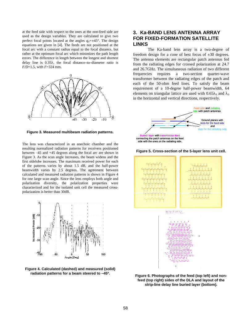
3. Ka-BAND LENS ANTENNA ARRAYFOR FIXED-FORMATION SATELLITELINKS
The Ka-band lens array is a two-degree offreedom design for a cone of best focus of ±30 degrees.The antenna elements are rectangular patch antennas fedfrom the radiating edges for crossed polarization at 24.7and 26.7GHz. The simultaneous radiation of two differentfrequencies requires a two-section quarter-wavetransformer between the radiating edges of the patch andeach of the 50-ohm feed lines. To satisfy the beamrequirement of a 10-degree half-power beamwidth, 64elements on triangular lattice are used with 0.65λ0 and λ0
in the horizontal and vertical directions, respectively.
Feed side and radiating side with patch antennas
Ground planes with slots for the feed side
andslots for the radiating side
Buried layer with transmission lines connecting the patch antennas on the feed
side with the ones on the radiating side.
Feed side and radiating side with patch antennas
Ground planes with slots for the feed side
andslots for the radiating side
Buried layer with transmission lines connecting the patch antennas on the feed
side with the ones on the radiating side.
Figure 5. Cross-section of the 5-layer lens unit cell.
Figure 6. Photographs of the feed (top left) and non-feed (top right) sides of the DLA and layout of the
strip-line delay line buried layer (bottom).
58

The patch pair is connected with slot couplers in theantenna ground planes to a common buried delay-line striplinelayer, as shown in Figure 5. The delay line lengths range from0.11λ to 1.05λ with the longest corresponding to the centralarray element. The array lattice is triangular, chosen to minimizegrating lobes when the beam is scanned. The photograph of thefabricated lens is shown in Figure 6. All substrates are TMM6Rogers substrates with a permittivity of 6 and a thickness of0.38mm. The measured radiation patterns are similar to thoseshown in Figure 3 [3].
4. LENS BEHAVIOR IN A MULTIPATHFADING CHANNEL
Based on the characterization of the arrays shown inthe previous sections, we expect to see improvements in a linkin a multipath fading environment when the lens is used at thefront end. In order to test this, the lens is placed in a simplecontrollable multipath environment consisting of a single metalreflector in an anechoic chamber, as shown schematically inFigure 7. The reflector is 15x15 free-space wavelengths largeand is translated in the x direction over three free-spacewavelengths. The reflector is positioned so that at x=0, thereflected wave from the transmitting horn falls into the secondnull of the lens antenna pattern for a receiver on the optical axis.In the first set of measurements, Figure 8a, the received powerin a line-of-sight link between the transmitting horn antenna andthe receiver patch, with no lens array present, was measuredwithout the presence of the mirror, and then as the mirror wastranslated in the x direction. The straight horizontal lines on theplots in Figure 8 are the measured power for the direct link only,without the reflector present. When the reflector is added, thereis a standing wave behavior typical of a multipath environment.When the lens array is placed in front of the receiving antenna,the multipath peak-to-null ratio is significantly reduced, partlydue to the gain of the array, and partly due to the built-in anglediversity.
MetallicMirror
Tx
Absorber
Lens Array
200 cm 158 cm42 cm42 cm
15°
−x
+x0
Focal Arc
A
B
Figure 7. Multipath measurement setup
When the receiver is positioned at point B on thefocal arc corresponding to a beam at 15 degrees, the referencelevel of the received signal without the mirror is 30 dB belowthe reference level measured with the feed on optical axis(straight solid lines in Figure 8). When the metallic mirror isplaced in the experiment, the level of the signal is on averageraised by 20 dB compared to the reference power level measuredwithout the mirror. Therefore, the reflected multipath signal isspatially separated from the direct signal, and the two arereceived separately and can subsequently be combined to obtainan increased signal level.
-25
-23
-21
-19
-17
-3 -2 -1 0 1 2 3 4 5 6
x [cm]
Po
wer
[d
Bm
]
(a)
-55
-45
-35
-25
-15
-3 -2 -1 0 1 2 3 4 5 6
x [cm]
Po
wer
[d
Bm
]
(b)
Figure 8. Multipath measurements for a beamat 0º (a) and at 15º (b).
5. AMPLITUDE CONTROLED SMALL-ANGLE BEAM STEERING OF A LENSARRAY
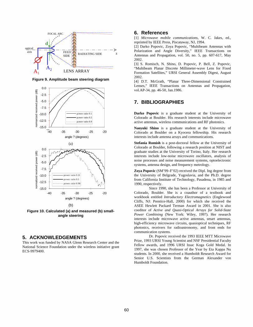
The lens array performs a discrete Fourier transform,in analogy to an optical dielectric lens performing a Fouriertransform. Because of this property of DLAs, amplitudevariations at the feed on the focal surface correspond to phaseshifts at the non-feed side, which in turn correspond to asteering of the beam. In order to demonstrate this principle, eachfeed of the dual-beam array was implemented with a 2-elementarray of patch antennas, spaced λ apart. The powerradiated/received by each element is controlled with variable-gain attenuators or amplifiers so that the ratio between them canbe varied to steer the beam, as illustrated in Fig.9.
The measured and simulated small-angle steering ofthe beam around its fixed position at +30 degrees, are shown inFig.10. The calculations were performed in Matlab, taking intoaccount the lens configuration, positions of the feeds andsimulated radiation patterns for the antenna elements. Theboundaries for small-angle steering are set by the angularpositions of the 2 elements of the feed, but depend also on thehalf-power beamwidth of the DLA.
59
LENS ARRAY
RADIATING SIDEFEEDSIDE
zoptical
axis
FOCAL ARC
d
A1A2
Figure 9. Amplitude beam steering diagram
-15.0
-12.5
-10.0
-7.5
-5.0
-2.5
0.0
-40 -35 -30 -25 -20
angle ? (degrees)
norm
ariz
ed r
ecei
ved
pow
er (
dB)
power ratio 0.1
power ratio 0.5
power ratio 0.9
(a)
-15.0
-12.5
-10.0
-7.5
-5.0
-2.5
0.0
-40 -35 -30 -25 -20
angle ? (degrees)
norm
aliz
ed r
ecei
ved
pow
er (
dB)
power ratio 0.13
power ratio 0.5
power ratio 0.98
(b)
Figure 10. Calculated (a) and measured (b) small-angle steering
5. ACKNOWLEDGEMENTSThis work was funded by NASA Glenn Research Center and theNational Science Foundation under the wireless initiative grantECS-9979400.
6. References[1] Microwave mobile communications, W. C. Jakes, ed.,reprinted by IEEE Press, Piscataway, NJ, 1994.[2] Darko Popovic, Zoya Popovic, “Multibeam Antennas withPolarization and Angle Diversity,” IEEE Transactions onAntennas and Propagation, vol. 50, no. 5, pp. 607-617, May2002.[3] S. Romisch, N. Shino, D. Popovic, P. Bell, Z. Popovic,“Multibeam Planar Discrete Millimeter-wave Lens for FixedFormation Satellites,” URSI General Assembly Digest, August2002.[4] D.T. McGrath, “Planar Three-Dimensional ConstrainedLenses,” IEEE Transactions on Antennas and Propagation,vol.AP-34, pp. 46-50, Jan.1986.
7. BIBLIOGRAPHIES
Darko Popovic is a graduate student at the University ofColorado at Boulder. His research interests include microwaveactive antennas, wireless communications and RF photonics.
Naoyuki Shino is a graduate student at the University ofColorado at Boulder on a Kyocera fellowship. His researchinterests include antenna arrays and communications.
Stefania Romish is a post-doctoral fellow at the University ofColorado at Boulder, following a research position at NIST andgraduate studies at the University of Torino, Italy. Her researchinterests include low-noise microwave oscillators, analysis ofnoise processes and noise measurement systems, optoelectronicsystems, antenna design, and frequency metrology.
Zoya Popovic (SM’99–F’02) received the Dipl. Ing degree fromthe University of Belgrade, Yugoslavia, and the Ph.D. degreefrom California Institute of Technology, Pasadena, in 1985 and1990, respectively.
Since 1990, she has been a Professor at University ofColorado, Boulder. She is a coauthor of a textbook andworkbook entitled Introductory Electromagnetics (EnglewoodCliffs, NJ: Prentice-Hall, 2000) for which she received theASEE Hewlett Packard Terman Award in 2001. She is alsocoeditor of Active and Quasi-Optical Arrays for Solid-StatePower Combining (New York: Wiley, 1997). Her researchinterests include microwave active antennas, smart antennas,high-efficiency microwave circuits, quasioptical techniques, RFphotonics, receivers for radioastronomy, and front ends forcommunication systems.
Dr. Popovic received the 1993 IEEE MTT MicrowavePrize, 1993 URSI Young Scientist and NSF Presidential FacultyFellow awards, and 1996 URSI Issac Koga Gold Medal. In1997, she was chosen Professor of the Year by Eta Kappa Nustudents. In 2000, she received a Humboldt Research Award forSenior U.S. Scientists from the German Alexander vonHumboldt Foundation.
60