transport platform sep serie · transport platform sep serie installation manual sep page 4 of 42...
TRANSCRIPT

Transport platform SEP Serie
Installation Manual SEP Page 2 of 42 Doc no. RD-7243-MA-002-02
Table of contents 1. Foreword .............................................................................................................................................................3
1.1. Revision table ................................................................................................................................................. 3
1.2. Documents and applied standards ................................................................................................................. 3
1.3. Manual content ............................................................................................................................................... 4
1.3.1. What does this manual hold contain? .................................................................................................... 4
1.3.2. Who must peruse this manual? ............................................................................................................. 4
1.3.3. Manual exclusions ................................................................................................................................ 4
2. Safety ..................................................................................................................................................................5 2.1. Warnings and symbols ................................................................................................................................... 5
2.2. Residual risks ................................................................................................................................................. 7
2.3. Operational and transport safety ..................................................................................................................... 7
2.4. Safety instructions .......................................................................................................................................... 8
2.4.1. Safety perimeter ................................................................................................................................... 8
2.4.2. Assembly and dismantling safety .......................................................................................................... 8
2.4.3. Maintenance safety ............................................................................................................................... 9
2.4.4. Promoting use of the user manual ........................................................................................................ 9
3. Installation instructions ................................................................................................................................... 10 4. Foundation ....................................................................................................................................................... 12 5. Bases ................................................................................................................................................................ 13
5.1. Base with adjustable jacks ............................................................................................................................ 13
6. Ground protection mesh .................................................................................................................................. 14 6.1. Assembly of the ground protection mesh, single mast .................................................................................. 15
7. Assembly .......................................................................................................................................................... 18 7.1. Installation of the first two mast sections ....................................................................................................... 19
7.2. Preparation of the platform ........................................................................................................................... 20
7.3. Lifting of the platform .................................................................................................................................... 22
7.4. Installation of the platform (continued) .......................................................................................................... 23
7.5. Close the top and bottom of the frame .......................................................................................................... 24
7.6. Slinging of the mast sections ........................................................................................................................ 25
7.7. Installation of mast attachments and anchors ............................................................................................... 26
7.8. Installation of the end mast section ............................................................................................................... 31
7.9. Installation with the self-erecting device (optional) ........................................................................................ 32
8. Dismantling ...................................................................................................................................................... 34 9. Level detection pads ........................................................................................................................................ 35
9.1. Buffer detection pads .................................................................................................................................... 35
9.2. 10'-0" (3,0m) descent detection pad ............................................................................................................. 36
9.3. DOWN detection pad .................................................................................................................................... 37
9.4. INTERMEDIATE and UP detection pads intermédiaire et haut ..................................................................... 38
9.5. End travel switches....................................................................................................................................... 39
10. Electrical connections ..................................................................................................................................... 40 Passing the cable through the mobile cable support .................................................................................................... 40
11. Cable guides ..................................................................................................................................................... 42
Transport platform SEP Serie
Installation Manual SEP Page 3 of 42 Doc no. RD-7243-MA-002-02
1. Foreword
1.1. Revision table
Revision no. Description Date (yyyy-mm-dd)
00 First issue 2017-10-16
01 Revision for first installation and test 2017-11-08
02 Revision after first installation and test 2017-12-12
1.2. Documents and applied standards • CSA B354.12-17 - Design, calculations, safety requirements, and test methods for mast
climbing transport platforms (MCTPs)
• CSA B354.13/14-17 - Safe use and best practices for mast climbing transport platforms (MCTPs)/ Training for mast climbing transport platforms (MCTPs)
• ANSI/SIA A92.10 – 2008 – American National standard for transport platforms Other documentation:
• User’s manual (RD-7243-MA-001)
• Parts book (RD-7243-MA-003)
• Safety device reset procedure SD2 (emergency centrifugal brake)
Transport platform SEP Serie
Installation Manual SEP Page 4 of 42 Doc no. RD-7243-MA-002-02
1.3. Manual content The present installation manual conveys all the important and necessary information to perform
the assembly and dismantling of the machine. This information is necessary for safe and
economic work with the machine.
Carefully read the present manual upon reception of the machine, before proceeding to assembly
and commissioning. Take time to observe all notes and pay attention to the safety instructions.
1.3.1. What is included in this manual? In this manual you will find information’s, advices and instructions regarding;
• Intended use and application domain
• Inherent and residual risks
• Safety
• Technical data
• Installation requirements
• Operation
• Fault, cause and troubleshoot
• Maintenance
• Customer’s service
1.3.2. Who must read this manual? • Installer and operator working on the machine.
• Machine maintenance staff (cleaning/maintenance)
1.3.3. Manual exclusions • This manual is not a user’s guide. For operation instructions and the option list, please
refer to the user’s manual (RD-7243-MA-001).

Transport platform SEP Serie
Installation Manual SEP Page 5 of 42 Doc no. RD-7243-MA-002-02
2. Safety
2.1. Warnings and symbols This manual is intended for any person called upon to proceed with assembly or dismantling of the platform and its structure. The machine is manufactured and assembled according to current technology and is safe for use. However, because of the nature of its utilization, the machine has components and sections that cannot be protected without preventing its proper functioning. For this reason, good personal safety practices must be followed to protect the staff and equipment. Risks may occur if the equipment is used incorrectly by untrained staff or to perform unintended operations. Training requirements:
• An operator must have successfully completed Level 1 (Safety and user) training and hold a valid training card, be familiar with the content of the present manual and master operation rules/regulations for the platform;
• An installer must have successfully completed Level 2A or 2B (Installation) training and hold a valid training card, be familiar with the content of the present manual and master operation rules/regulations for the platform;
• Before assembly, disassembly, operation or maintenance of the platform, you must read and perfectly understand instructions found in the present manual, as well as the installation manual. Not conforming to these safety instructions may general material damages, severe wounds and even death. FRACO and/or its representative can in no case be held responsible. All local norms and regulations applicable concerning safety and prevention of accidents, environmental protection and all other activity related to assembly, disassembly, operation and maintenance of this type of equipment are considered a supplement to the present manual and must imperatively be respected, for example; the use of individual protection equipment (harness, helmet, boots, etc.).
• If the machine is installed in an area accessible to the public, access to the working zone must be restrained with a fence of MINIMUM 8,20 ft (2,5 m) high. The operator of the machine has the responsibility to check the stability and solidity of the fence.
• Safety is our priority! For this reason, never remove of modify a part to adapt the platform to a different condition. Contact FRACO or its representative for any assistance.
• Use only parts from the official list of parts. ∞ REFER TO THE PARTS BOOK (RD-7243-MA-003).
• Keep this manual close to the machine. This manual is considered an integral part of the platform and is mandatory to communicate the necessary safety information to the operators and installers. A copy of this manual must always be included in the waterproof tool compartment of the platform intended for this purpose.
• Stickers and warnings. Make sure to read and understand all the stickers, warnings and instructions posted on the equipment, or to get explanation from a qualified person.

Transport platform SEP Serie
Installation Manual SEP Page 6 of 42 Doc no. RD-7243-MA-002-02
Remember:
• For safety reasons, a minimum of two (2) persons must be present on each platform at all time during assembly, dismantling, maintenance or operation.
• Local regulation may require that the platform be permanently equipped with a fire extinguisher. Its location on the platform must be clearly indicated to be easily found.
• In case of FIRE: Remain calm and warn the persons present on the platform. If available, use the fire extinguisher and follow its instructions. If the fire is out of control, evacuate the platform by the nearest exit access.
• Local regulation may require appropriate protection of the platform in case of an electrical storm.
• Work on the platform only if wearing tight-fitting clothing, security boots and a helmet in accordance with local regulation in effect. Do not wear jewelry such at necklaces and rings as it may induce a risk of jamming and pulling.
• IMPORTANT! Refer to the SECTION 2 SAFETY, ON PAGE 5 for the additional safety instructions regarding the operation of the platform. ∞SEE SECTION 2 SAFETY, ON PAGE 5. If, after having consulted this manual, you have doubts regarding the assembly, dismantling, maintenance and use of the platform, contact your FRACO representative.
• Consequences of violation of safety instructions; violation of safety instructions may put staff, environment and machine in danger. Violation may lead to the cancellation of all indemnities.
In this manual, the following symbols and annotations are used:
Symbols Description
Danger
Major risks for physical and/or material damages for survival and safety
Warning! Risks of physical and/or material damages
Important! Important points to monitor to conform with proper functioning of the machine
Note Additional of complementary information
Table 1 - Symbols and annotations

Transport platform SEP Serie
Installation Manual SEP Page 7 of 42 Doc no. RD-7243-MA-002-02
2.2. Residual risks Despite all precautions taken, potential residual risks remain such as:
• Wounds from uncoordinated tasks
• Malfunction of a control system
• Work with an electric system
• Damage to the transport equipment
• Fall of inappropriately secured objects
• Strong winds
• Entrance and exit
• Loud noises
• Dust
• Or any other work-related inherent risk, etc.
2.3. Operational and transport safety During the operation of the machine, be sure to follow the following safety instructions;
• Respect the load capacity of the equipment.
• Use the machine only in the absence of technical defects; use being conscious of the safety measures and risks while observing the user guide.
• Immediately correct defects that may affect safety.
• Immediately stop the machine if there are changes relative to the safety of the machine or its operative behaviour and report the problem to management or its representative.
• Do not modify the machine by adding parts that are not included in the original parts list. This also applies the installation and adjustments of security devices, such as end travel detectors.
• Do not modify, replace or bypass safety devices. • Immediately replace damaged, illegible or missing signs and notices, as well as safety
stickers. ∞ SEE THE LIST OF DATA PLATES AND STICKERS IN THE USER GUIDE (RD-7243-MA-001).
• If work is interrupted, turn off the machine with the main switch and lock with a padlock.
In situations representing a danger for the operating staff of the machine, turn off the machine by pressing the EMERGENCY STOP button. ∞ SEE SECTION "EMERGENCY STOP BUTTON" IN THE USER’S GUIDE (RD-7243-MA-001).
• Lower and stop the machine when winds exceed > 35 mi/h (> 55 km/h). If winds exceeding >70 mi/h (> 117 km/h) are expected, secure the unit to the ground. If in doubt, consult effective local regulation and/or your FRACO representative.
• Always protect the machine from unauthorized use.
• Safely distribute load on the platform. Any material that may slide or fall must be anchored correctly.
• Do not stand or work beneath the platform!
• Do not place objects beneath the platform.
(Image for reference only))
(Image for reference only)

Transport platform SEP Serie
Installation Manual SEP Page 8 of 42 Doc no. RD-7243-MA-002-02
• Evenly position loads on the platform and respect maximum distribution.
• Store materials at a secure distance of at least 20" (50cm) of any moving part of the machine.
• The user must ensure that the area where the machine is installed is clean and uncluttered, as specified in the instructions.
• Any person accompanying the operator must conform to its given instructions. More particularly, the person must not step over the material being transported in the platform.
• Identify damages, sounds and defects externally recognizable. Immediately signal all functioning changes or defect to the management of the company or its authorised representatives and turn off and secure the machine immediately.
• Important! Adequately illuminate the platform during night shifts and where light is necessary.
2.4. Safety instructions
2.4.1. Safety perimeter • Limit a sufficient safety perimeter and prohibit access around the base, platform and any
risk area around the later. This must be done in accordance with effective local safety standards and regulations. No object or debris should be stored within this perimeter.
2.4.2. Assembly and dismantling safety • Important! Observe the specified tightening torques for the bolting of risk elements (mast
sections and rack segments).
• The machine must be assembled and dismantled in accordance with the installation manual and under the supervision of an authorized person specified by the contractor.
• The user is responsible, during assembly/dismantling, as well as during operation and maintenance, of dictating instructions concerning the machine to any persons present for all to be effectively informed of safety instructions.
• The user must make sure no unauthorized person is present on or in proximity of the machine.
• Assemble the equipment in an exactly vertical and stable position, and anchor it to the building.
• Before beginning work on the place of use, familiarize yourself with the work environment, for example obstacles in the work area, bearing capacity of the ground and necessary protection of the construction site.
• Load and transport only material that has been carefully dismantled, wrapped and solidly anchored.

Transport platform SEP Serie
Installation Manual SEP Page 9 of 42 Doc no. RD-7243-MA-002-02
2.4.3. Maintenance safety • Inspect before putting into service. Recurrent and periodic inspections must be performed
according to the instructions in this manual, as well as according to local standards and regulations.
• Workers must be informed regarding type and scope of periodic inspections.
• Results of periodic inspections must be recorded in the appendix of the present user’s manual.
• Turn off the machine (turn off main power supply) before maintenance.
• The platform must be secured with the appropriate material (travel blocking mechanism) when work is being undertaken under the machine.
• Authorised maintenance and repair work must be performed only by authorised and qualified persons. Pay attention to the risks inherent to work on electric systems. Respect local standards and regulations in effect regarding electrical work.
• Correctly reassemble and verify all dismantled safety devices when maintenance is completed.
• Important! Independent conversions and modifications made to the machine compromise safety and are not authorised.
• All spare parts must comply to the technical requirements of the manufacturer. Only use replacement parts of FRACO origin.
∞ REFER TO THE PARTS BOOK (RD-7243-MA-003).
2.4.4. Promoting use of the user’s manual User’s/installation manuals contain rules and reference to be considered by a contractor or
group of contractors and are contractual instructions delivered as part of management rights.
Employees are required to follow these instructions. The contractor must follow the
instructions for the prevention of working accidents and must inform the insured of the risks
inherent to their work as well as takes measures to avoid these risks
Transport platform SEP Serie
Installation Manual SEP Page 10 of 42 Doc no. RD-7243-MA-002-02
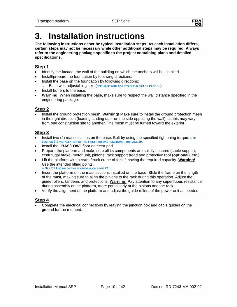
3. Installation instructions The following instructions describe typical installation steps. As each installation differs, certain steps may not be necessary while other additional steps may be required. Always refer to the engineering package specific to the project containing plans and detailed specifications.
Step 1 • Identify the facade, the wall of the building on which the anchors will be installed.
• Install/prepare the foundation by following directions.
• Install the base on the foundation by following directions: o Base with adjustable jacks (SEE BASE WITH ADJUSTABLE JACKS ON PAGE 13)
• Install buffers to the base.
• Warning! When installing the base, make sure to respect the wall distance specified in the engineering package.
Step 2 • Install the ground protection mesh. Warning! Make sure to install the ground protection mesh
in the right direction (loading landing door on the side opposing the wall), as this may vary from one construction site to another. The mesh must be turned toward the exterior.
Step 3
• Install two (2) mast sections on the base. Bolt by using the specified tightening torque. SEE
SECTION 7.1 INSTALLATION OF THE FIRST TWO MAST SECTIONS , ON PAGE 19.
• Install the "BAS/LOW" floor detector pad.
• Prepare the platform and make sure all its components are solidly secured (cable support, centrifugal brake, motor unit, pinions, rack support tread and protective roof (optional), etc.).
• Lift the platform with a crane/truck crane of forklift having the required capacity. Warning! Use the intended lifting points. ∞ SEE 7.3 LIFTING OF THE PLATFORM, ON PAGE 22.
• Insert the platform on the mast sections installed on the base. Slide the frame on the length of the mast, making sure to align the pinions to the rack during this operation. Adjust the guide rollers, tandems and protections. Warning! Pay attention to any superfluous resistance during assembly of the platform, more particularly at the pinions and the rack.
• Verify the alignment of the platform and adjust the guide rollers of the power unit as needed.
Step 4 • Complete the electrical connections by leaving the junction box and cable guides on the
ground for the moment.

Transport platform SEP Serie
Installation Manual SEP Page 11 of 42 Doc no. RD-7243-MA-002-02
Step 5 • Assemble up to six (6) mast sections together on the ground. Warning! Make sure that you
have the correct mast sections during the entire the assembly process (correct model number, direction of the rack). Also make sure that the mast sections are in good condition; no steel deformation may be present.
• Lift the assembled mast using a crane/truck crane.
• By using a crane/truck crane or an access scaffolding, bolt the mast sections together. Warning! If you dispose of a self-erecting device (available on option), refer to SECTION 7.9
INSTALLATION WITH THE SELF-ERECTING DEVICE (OPTIONAL), ON PAGE 32.
• Progressively install the «INTERMÉDIAIRE/INTERMEDIATE» floor detector pads.
Step 6
• By using a crane/truck crane, an access scaffolding, or the platform installation tailgate, install the anchors to the wall.
• Install the mast attachments to the mast and fasten the turnbuckles to the anchors.
• Adjust the turnbuckles to correct the verticality of the mast. Warning! Refer to the engineering package for instructions specific to the type of anchor and levels of installation.
WARNING! Never install more than 30'-0" (9,15m) of mast sections over the last anchor installed (the highest anchor).
• When the two first mast tie systems are installed, the adjustable jacks outriggers from the ground base must be removed (SEE BASE WITH ADJUSTABLE JACKS, ON PAGE 13).
Step 7 • Repeat steps 5 and 6 until the total height specified in the engineering package is reached.
• Install the "HAUT/HIGH" floor detector pad.
• Install the junction box(es)
• Install a cable guide every 20'-0" (6,0m) maximum.
• Complete the final electrical installation. ∞ REFER TO THE ELECTRICAL DIAGRAM SPECIFIC TO THE PROJECT. ∞ REFER TO SECTION 10 ELECTRICAL CONNECTIONS, ON PAGE 40.
Step 8 • Complete assembly by installing the end mast section (mast section with no rack and painted
red).
Step 9 Validate the position of all floor detector pads. ∞ SEE SECTION 9 LEVEL DETECTOR PADS, FROM PAGE 35
Step 10 Install the landing doors. Connect the landing doors to the safety line, in accordance with the electrical diagram.

Transport platform SEP Serie
Installation Manual SEP Page 12 of 42 Doc no. RD-7243-MA-002-02
4. Foundation
Place the foundation on the
ground and install high enough
to be above the level of the
threshold of the ground mesh.
No drain required.
Place the foundation on the
ground and install high enough
to be level with the threshold of
the ground mesh. No drain
required.
Place the foundation on the
ground and install low enough
to be below the level of the
threshold of the ground mesh.
A drain is required!
Install a foundation sufficiently resistant to distribute the load of the mast in the ground. This foundation may be made of a steel plate, a concrete slab, or crushed stone. The following example suggests the use of crushed stone overlayered with a concrete slab. Steps: 1. Level the ground under the base with 0-
3/4″ crushed stone for a [4,0″ (100 mm) à 6″ (150 mm)] thickness respecting the dimensions of the base.
2. Depending of the height of installation, it is possible to use another type of foundation (concrete slab, steel plate, supporting structure, etc.) provided it is signed and approved by a sufficiently experienced engineer.
3. Mark the dimension of the ground base on
the crushed stone foundation with precision. Respecting a clearing of MINIMUM 4,0″ (100 mm) around tour. Mark the center in front of the foundation, facing the wall.
4. The dimensions of the foundation are
specific to the installation (model, height of installation, platform configuration) and are specified in the engineering package specific to the project.
5. Verify leveling of the stone foundation with
a spirit level and verify perpendicularity in relation to the wall.
6. The foundation must be level with the
ground. If not, the ground must be drained.
7. If there is a risk of freezing, the foundation must be isolated.
8. Complete foundation specifications must
be detailed in the engineering package specific to the project.
9. The total weight of the SEP and mast
sections is transferred to the ground through the base of the machine. (REFER TO
THE USER’S MANUAL RD-7243-MA-001).
Central mark
WA
LL
MIN 4,0"
(100 mm)
MIN
4,0"
(100 mm)
Steel plate – concrete slab – crushed stone

Transport platform SEP Serie
Installation Manual SEP Page 13 of 42 Doc no. RD-7243-MA-002-02
Figure 1 –Base with jacks and buffer assembly
5. Bases
5.1. Base with adjustable jacks • Install the base by respecting the distances specified in the engineering package.
• Warning! Install the installation outriggers. Remove these outriggers once the first two (2) mast anchors are installed.
• Warning! Do not forget to later remove the outriggers as they are useful only during assembly and will interfere with the functioning of the buffers during normal operation. Must be removed once the first two (2) mast anchors are installed.
• Assemble the buffers to the base by using the supplied bolting kits.
No. Qty Item Description
1 1 RD-7243-BA-100 Bolted base for mast section 26" x 26"
2 1 RD-7243-BA-102 Left base outrigger
3 1 RD-7243-BA-106 Right base outrigger
4 1 RD-7243-BA-107 SEP Spring buffer assembly
5 2 BOZ-7221 Bolt 5/8"-11unc x 5-1/2" gr5 zinc
6 8 BOZ-7227 Bolt 3/4"-10unc x 2-1/2" gr5 zinc
7 2 NYL-2040 Nylon lock nut 5/8"-11unc gr5 zinc
8 8 NYL-2050 Nylon lock nut 3/4"-10unc gr5 zinc
9 4 WAZ-7041 Washer 5/8" SAE zinc
10 16 WAZ-7051 Washer 3/4" SAE zinc
2
1
4
3
5
3
4
4
3
5
1
Foundation

Transport platform SEP Serie
Installation Manual SEP Page 14 of 42 Doc no. RD-7243-MA-002-02
Variable dim.
17'-4"
(5,3 m)
11'-3"
(3,4 m)
5'-0"
(1,5 m)
12"
(304 mm)
Figure 2 – Ground mesh (example)
6. Ground protection mesh
Standard application
• Side « A » is the platform ground access.
• Side « B » is the level transfert point. Note: Sides « A » and « B » may be inverted as needed during assembly.
• Side « C » (optional) is linked to Side « A » or « B » during assembly.
Ground protection mesh
Platform Side A Side B
Side C
MAST
Variable dim.
13'-2" (4,0 m)
4'-9"
(1,4 m)

Transport platform SEP Serie
Installation Manual SEP Page 15 of 42 Doc no. RD-7243-MA-002-02
Figure 3 – Ground protection mesh and adjustment
6.1. Ground protection mesh assembly, single mast This example displays a single mast machine, assembled to the right side of the mast. Note
that the direction of the assembly must be inverted for a machine assembled to the left of the
mast.
Step 1 – Left panel Install the left panel of the mesh (RD-7243-GS-102), with the mesh turned outwards. Place the mesh panel against the ground base and refer to the dimensions below.
Adjust the height of the feet of the base.
(RD-7243-GS-102) 30-9/16" (776mm)
24" (610mm)
Example: dimensions for platform installed to
the right of the mast
Transport platform SEP Serie
Installation Manual SEP Page 16 of 42 Doc no. RD-7243-MA-002-02
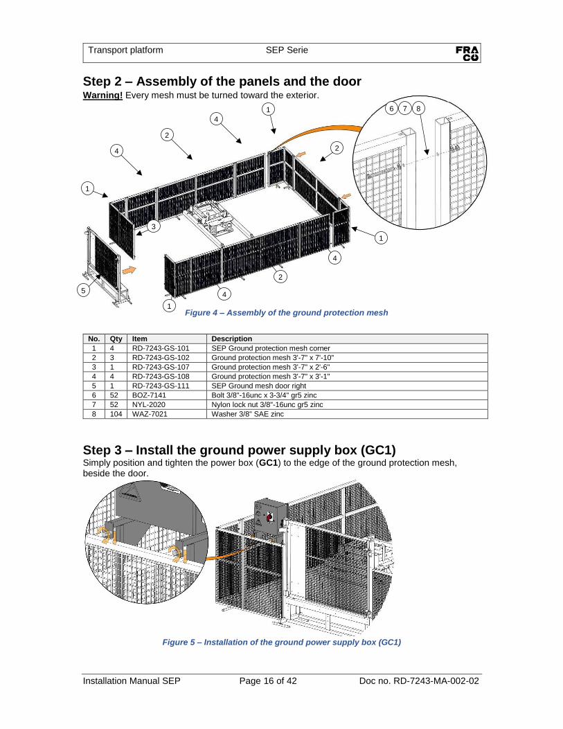
Figure 4 – Assembly of the ground protection mesh
Step 2 – Assembly of the panels and the door Warning! Every mesh must be turned toward the exterior.
No. Qty Item Description
1 4 RD-7243-GS-101 SEP Ground protection mesh corner
2 3 RD-7243-GS-102 Ground protection mesh 3'-7" x 7'-10"
3 1 RD-7243-GS-107 Ground protection mesh 3'-7" x 2'-6"
4 4 RD-7243-GS-108 Ground protection mesh 3'-7" x 3'-1"
5 1 RD-7243-GS-111 SEP Ground mesh door right
6 52 BOZ-7141 Bolt 3/8"-16unc x 3-3/4" gr5 zinc
7 52 NYL-2020 Nylon lock nut 3/8"-16unc gr5 zinc
8 104 WAZ-7021 Washer 3/8" SAE zinc
Step 3 – Install the ground power supply box (GC1) Simply position and tighten the power box (GC1) to the edge of the ground protection mesh, beside the door.
Figure 5 – Installation of the ground power supply box (GC1)
2
4
4
1
1
1
2
4
4
1
3
2
5
8
7
6

Transport platform SEP Serie
Installation Manual SEP Page 17 of 42 Doc no. RD-7243-MA-002-02
Figure 6 - Installation of the cable barrel
Step 4 – Install the power cable barrel Install the barrel to the left of the base and bolt it to the base.
No. Qty Item Description
1 1 RD-7243-ME-100 Electric cable barrel SEP
2 2 BOZ-7227 Bolt 3/4"-10unc x 2-1/2" gr5 zinc
3 2 NYL-2050 Nylon lock nut 3/4"-10unc gr5 zinc
4 4 WAZ-7051 Washer 3/4" SAE zinc
4
3
2
1
Warning! Verify the verticality of the barrel with a level. If
the barrel is not straight, there is possibility of conflict with
the platform when it descends.
Warning! Possibility of
conflict if the barrel is
not level Adjust the level

Transport platform SEP Serie
Installation Manual SEP Page 18 of 42 Doc no. RD-7243-MA-002-02
Figure 7 - Installation of the platform cable support
7. Assembly Complete the assembly of the platform, including options (protection roof, cable support, etc.). For more detail on the options and their installation, refer to the User’s manual (RD-7243-MA-001).
No. Qty Item Description
1 1 RD-7243-ME-114 SEP cable support cable 30mm - 40mm diameter
2 4 BOZ-7157 Bolt 1/2"-13unc x 1-3/4" gr5 zinc
3 2 LOZ-5030 Lock washer 1/2" zinc
4 2 NYL-2030 Nylon lock nut 1/2"-13unc gr5 zinc
5 4 WAZ-7031 Washer 1/2" SAE zinc
1
5
4
2
5
3
2
Transport platform SEP Serie
Installation Manual SEP Page 19 of 42 Doc no. RD-7243-MA-002-02
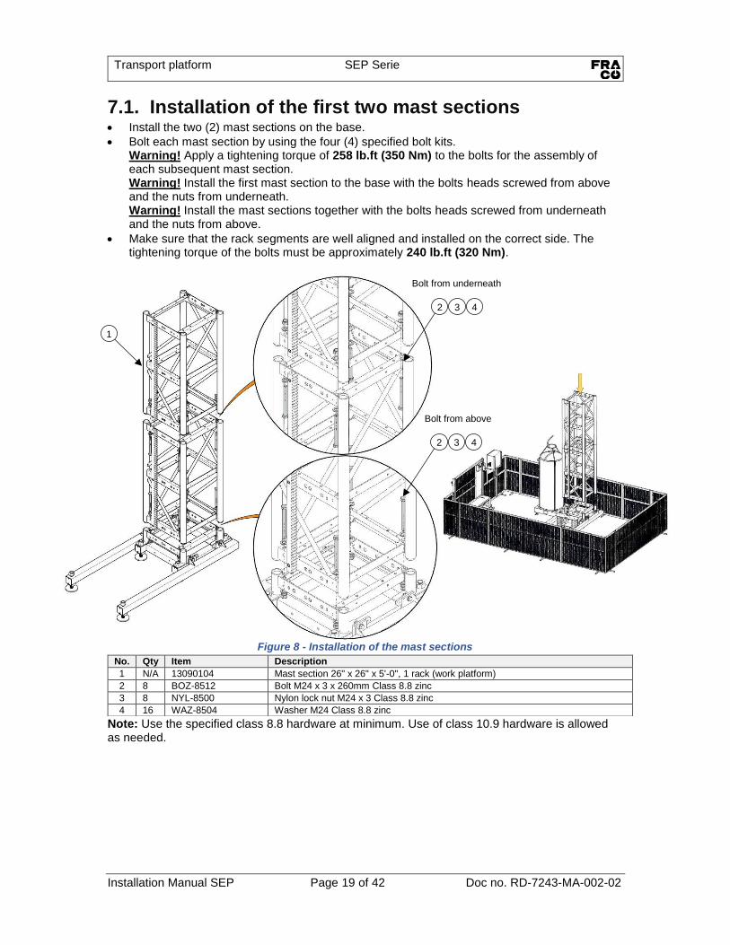
Figure 8 - Installation of the mast sections
7.1. Installation of the first two mast sections • Install the two (2) mast sections on the base.
• Bolt each mast section by using the four (4) specified bolt kits. Warning! Apply a tightening torque of 258 lb.ft (350 Nm) to the bolts for the assembly of each subsequent mast section. Warning! Install the first mast section to the base with the bolts heads screwed from above and the nuts from underneath. Warning! Install the mast sections together with the bolts heads screwed from underneath and the nuts from above.
• Make sure that the rack segments are well aligned and installed on the correct side. The tightening torque of the bolts must be approximately 240 lb.ft (320 Nm).
Note: Use the specified class 8.8 hardware at minimum. Use of class 10.9 hardware is allowed as needed.
No. Qty Item Description
1 N/A 13090104 Mast section 26" x 26" x 5'-0", 1 rack (work platform)
2 8 BOZ-8512 Bolt M24 x 3 x 260mm Class 8.8 zinc
3 8 NYL-8500 Nylon lock nut M24 x 3 Class 8.8 zinc
4 16 WAZ-8504 Washer M24 Class 8.8 zinc
1
4
3
2
Bolt from underneath
4
3
2
Bolt from above
Transport platform SEP Serie
Installation Manual SEP Page 20 of 42 Doc no. RD-7243-MA-002-02
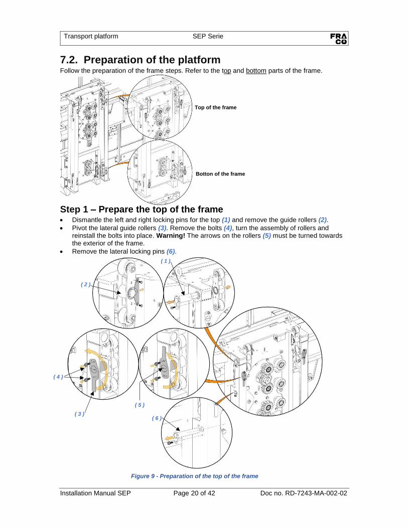
Figure 9 - Preparation of the top of the frame
7.2. Preparation of the platform Follow the preparation of the frame steps. Refer to the top and bottom parts of the frame.
Step 1 – Prepare the top of the frame • Dismantle the left and right locking pins for the top (1) and remove the guide rollers (2).
• Pivot the lateral guide rollers (3). Remove the bolts (4), turn the assembly of rollers and reinstall the bolts into place. Warning! The arrows on the rollers (5) must be turned towards the exterior of the frame.
• Remove the lateral locking pins (6).
Top of the frame
Botton of the frame
( 2 )
( 1 )
( 3 )
( 4 )
( 5 )
( 6 )
Transport platform SEP Serie
Installation Manual SEP Page 21 of 42 Doc no. RD-7243-MA-002-02
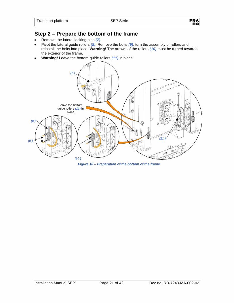
Step 2 – Prepare the bottom of the frame • Remove the lateral locking pins (7).
• Pivot the lateral guide rollers (8). Remove the bolts (9), turn the assembly of rollers and reinstall the bolts into place. Warning! The arrows of the rollers (10) must be turned towards the exterior of the frame.
• Warning! Leave the bottom guide rollers (11) in place.
(7 )
(9 )
(8 )
(10 )
Leave the bottom guide rollers (11) in
place
(11 )
Figure 10 – Preparation of the bottom of the frame
Transport platform SEP Serie
Installation Manual SEP Page 22 of 42 Doc no. RD-7243-MA-002-02
Figure 12 - Lifting with a crane
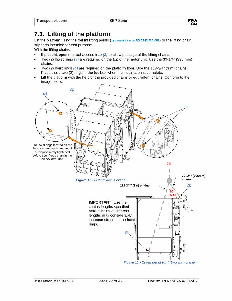
7.3. Lifting of the platform Lift the platform using the forklift lifting points (SEE USER’S GUIDE RD-7243-MA-001) or the lifting chain
supports intended for that purpose.
With the lifting chains;
• If present, open the roof access trap (2) to allow passage of the lifting chains.
• Two (2) lhoist rings (3) are required on the top of the motor unit. Use the 39-1/4" (996 mm) chains.
• Two (2) hoist rings (4) are required on the platform floor. Use the 118-3/4" (3 m) chains. Place these two (2) rings in the toolbox when the installation is complete.
• Lift the platform with the help of the provided chains or equivalent chains. Conform to the image below.
118-3/4" (3m) chains
39-1/4" (996mm) chains
CG
(2)
(3)
60° MAX
(3)
(1)
(2)
Figure 11 - Chain detail for lifting with crane
The hoist rings located on the floor are removable and must
be appropriately tightened before use. Place them in the
toolbox after use.
IMPORTANT! Use the chains lengths specified here. Chains of different lengths may considerably increase stress on the hoist rings.

Transport platform SEP Serie
Installation Manual SEP Page 23 of 42 Doc no. RD-7243-MA-002-02
Figure 13 – Installation of the platform on the first mast sections
7.4. Installation of the platform (continued) • Lift the platform and position it with the frame beside the mast. Gently slide the frame by the
side and align the gears and the segments of the rack. Warning! At all times during the
installation of the platform, pay attention to any resistance, particularly at the pinions and
rack. Cease installation and isolate the source of the conflict before proceeding. The pinions
must mesh and turn easily. • It is recommended to position yourself behind the mast to visualise correctly the inside of the
frame during installation. Warning! Keep the platform supported at all time until the installation of the first two mast anchors.
Place yourself behind the mast and insure the alignment of the gears and the rack.
Important! The arrows of the four (4) guide roller supports must be turned outwards.
Warning! Make sure to remove the final end travel detector. It is not necessary to disconnect the detector. Important! Do not forget to reinstall the detector once the installation of the frame is completed.
Warning! Conflict during installation of the frame.
Remove detector temporarily

Transport platform SEP Serie
Installation Manual SEP Page 24 of 42 Doc no. RD-7243-MA-002-02
Figure 14 – Closing of the frame
7.5. Close the top and bottom of the frame • Always install the four (4) safety locking pins (1) first, starting with the top of the frame.
• Next, install the top guide rollers (2). Make sur to install the axes of the left rollers (3) on the left and do the same for the right rollers. There is a left "L" symbol and a right "R" symbol at the ends of the axes.
• Put back the four (4) axes of the lateral guide rollers (4) in the right direction. The arrows must point towards the interior of frame.
( 1 )
( 3 )
( 2 ) ( 2 )
( 4 )
( 4 )
Important! Keep the assembly suspended and secured during installation until the installation of the first two (2) wall anchors.
Transport platform SEP Serie
Installation Manual SEP Page 25 of 42 Doc no. RD-7243-MA-002-02
Figure 15 – Slinging of the mast sections
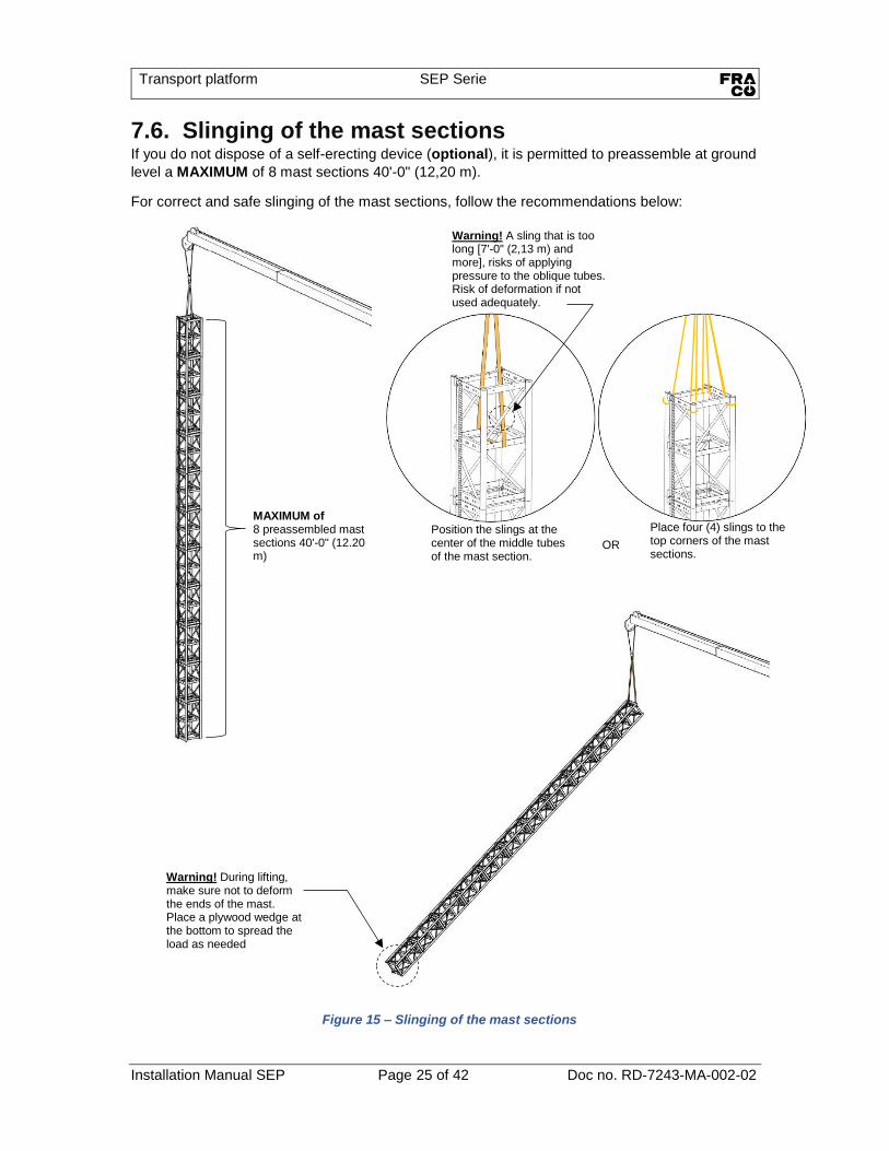
7.6. Slinging of the mast sections If you do not dispose of a self-erecting device (optional), it is permitted to preassemble at ground
level a MAXIMUM of 8 mast sections 40'-0" (12,20 m).
For correct and safe slinging of the mast sections, follow the recommendations below:
MAXIMUM of 8 preassembled mast sections 40'-0" (12.20 m)
Position the slings at the center of the middle tubes of the mast section.
Place four (4) slings to the top corners of the mast sections.
OR
Warning! A sling that is too long [7'-0" (2,13 m) and more], risks of applying pressure to the oblique tubes. Risk of deformation if not used adequately.
Warning! During lifting, make sure not to deform the ends of the mast. Place a plywood wedge at the bottom to spread the load as needed

Transport platform SEP Serie
Installation Manual SEP Page 26 of 42 Doc no. RD-7243-MA-002-02
7.7. Installation of mast attachments and anchors • Install mast sections by completing assembly of mast attachments and anchors
progressively. For the bolting of the mast sections, conform to the instructions of SECTION 7.1
INSTALLATION OF THE FIRST TWO MAST SECTIONS , ON PAGE 19.
• Install the first anchor at MAX 20'-0" (6,0m) from the ground.
• The typical distance between the following anchors is 30'-0" (9,0m) [MIN 20'-0" (6,0m) - MAX 40'-0" (12,0m)]. Important! Follow the assembly specifications described in the user guide. ∞ SEE USER’S MANUAL RD-7243-MA-001, SECTION 4 TECHNICAL DATA.
MAST ATTACHMENTS AND ANCHORS For any information on detailed parts, on FRACO part numbers and engineering data specific to different mast anchor devices, refer to the most recent "MAST ANCHOR SPECIFICATIONS" documents available and the engineering package specific to the project. Contact your FRACO representative for a copy of these documents. Attachments may be installed from above of from below to satisfy at best the MAXIMUM inclination of 15°.
Attachments installed from above
Attachments installed from below
Figure 16 - Installation of mast attachments

Transport platform SEP Serie
Installation Manual SEP Page 27 of 42 Doc no. RD-7243-MA-002-02
Installation of mast ties Step 1 Use the roof access trap to access installation bolts.
No. Qty Item Description
1 2 21010037 Wall tie fixation
2 8 BOZ-8569 Bolt 5/8"-11unc x 2" gr8 zinc
3 8 NYL-8512 Nylon lock nut 5/8"-11unc gr8 zinc
4 8 WAZ-7041 Washer 5/8" SAE zinc
Attachments installed from above
Attachments installed from bellow
1
4
3
2
Figure 17 - Installation of mast attachment fixtures
Transport platform SEP Serie
Installation Manual SEP Page 28 of 42 Doc no. RD-7243-MA-002-02
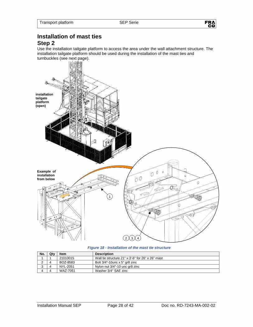
Figure 18 - Installation of the mast tie structure
Installation of mast ties Step 2 Use the installation tailgate platform to access the area under the wall attachment structure. The installation tailgate platform should be used during the installation of the mast ties and turnbuckles (see next page).
No. Qty Item Description
1 1 21010015 Wall tie structure 21" x 3'-6" for 26" x 26" mast
2 4 BOZ-8583 Bolt 3/4"-10unc x 5" gr8 zinc
3 4 NYL-2051 Nylon nut 3/4''-10 unc gr8 zinc
4 4 WAZ-7051 Washer 3/4" SAE zinc
4
3
2
1
installation tailgate platform (open)
Example of installation from below

Transport platform SEP Serie
Installation Manual SEP Page 29 of 42 Doc no. RD-7243-MA-002-02
Figure 19 - Installation of mast tie turnbuckles
Installation of mast ties Step 3
No. Qty Item Description
1 3 23080014 Turnbuckle 3.000" x 4'-7" to 7'-1" Assembly
2 3 BOZ-7250 Bolt 3/4"-10unc x 5" gr5 zinc
3 6 BOZ-8584 Bolt 1"-8unc x 5" gr8 zinc
4 3 NYL-2050 Nylon lock nut 3/4"-10unc gr5 zinc
5 6 NYL-2061 Nylon lock nut 1"-8unc gr8 zinc
6 3 WAZ-7051 Washer 3/4" SAE zinc
7 12 WAZ-7071 Washer 1" SAE zinc
1
6
4
2
7
5
3
15°
15°
MAX distance
9,5" (240 mm)
Attention! MAXIMUM permitted angle for the turnbuckles is ±15°.
Alternate the side of the center turnbuckle at each mast tie alternate installation
Figure 20 – Turnbuckles installation details

Transport platform SEP Serie
Installation Manual SEP Page 30 of 42 Doc no. RD-7243-MA-002-02
Figure 22 - Installation of wall anchors
Distance « L=100" (2,54 m) » and « B=30" (0.76 m) ». For anchor forces to the wall, refer to the user guide. Important! Always refer to the engineering package specific to the project.
Step 4 Install the concrete anchor bolts or other fixations approved and specified in the engineering package.
No. Qty Item Description
1 2 24030010 SEH 2 point concrete anchors 8" x 8"
2 2 BOZ-7304 Bolt 1"-8unc x 6-1/2" gr8 zinc yellow
3 2 NYL-2061 Nylon lock nut 1"-8unc gr8 zinc
« L »
« B » « B/2 »
By
Ay
Ax
F
Figure 21 - Dimensions and forces to the wall
concrete anchor bolts
or other
3
2
1
Transport platform SEP Serie
Installation Manual SEP Page 31 of 42 Doc no. RD-7243-MA-002-02
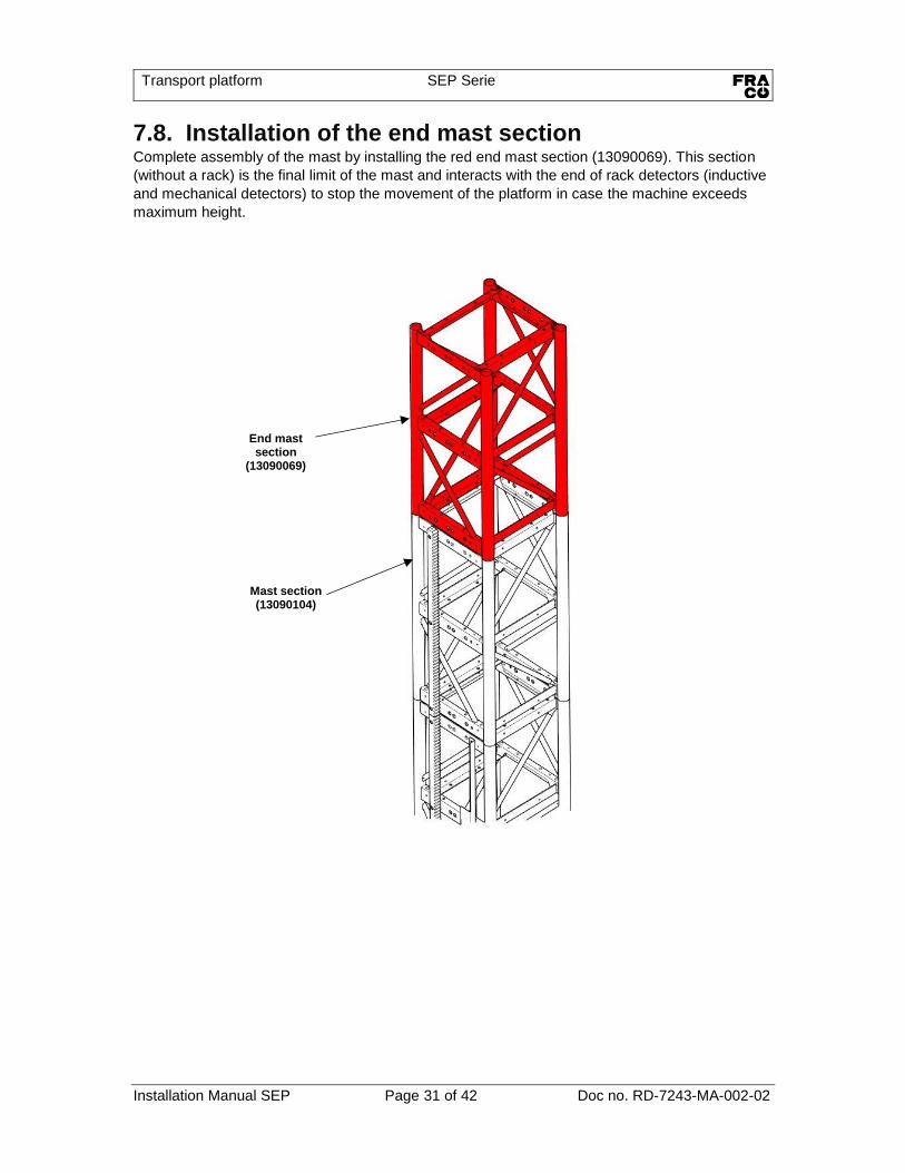
7.8. Installation of the end mast section Complete assembly of the mast by installing the red end mast section (13090069). This section
(without a rack) is the final limit of the mast and interacts with the end of rack detectors (inductive
and mechanical detectors) to stop the movement of the platform in case the machine exceeds
maximum height.
End mast section
(13090069)
Mast section (13090104)

Transport platform SEP Serie
Installation Manual SEP Page 32 of 42 Doc no. RD-7243-MA-002-02
Figure 23 - Installation of the self-erecting device
Figure 24 – Self-erecting device operation
7.9. Installation with the self-erecting device (optional) • It is possible to use the self-erecting device (optional) to gradually install mast sections
from the platform.
• Install the self-erecting device in accordance with the instructions and operate the device
in accordance with the information provided in the user’s manual (RD-7243-MA-001).
• Important! The first two (2) mast anchors must be installed before using the device.
Limit switch
Spring-plunger
Important! Install the safety pin
(GOU-5040)
Boom of self-erecting device
(RD-7243-AE-100)
Operating the platform is not possible if the limit switch is disactivated
and/or the roof access trap is
open

Transport platform SEP Serie
Installation Manual SEP Page 33 of 42 Doc no. RD-7243-MA-002-02
Figure 25 - Installation of mast section with the self-erecting device

Transport platform SEP Serie
Installation Manual SEP Page 34 of 42 Doc no. RD-7243-MA-002-02
8. Dismantling Before proceeding with dismantling, authorised staff should verify the following: • Verify that there were no significant changes or modifications compared to the original
assembly. Examples of changes that may affect the safety of dismantling operations: freed or missing mast ties, loose bolts, different ground load distribution conditions or alterations of the base, etc.
• Verify the presence of signs of stress or weakness on mast sections, mast ties, platform or base that may affect the safety of dismantling operations.
• Verify that the base provides sufficient stability in all directions to support the structure while dismantling the last two (2) mast anchors.
• Know the maximum quantity of mast ties and additional equipment the platform can transport during the different steps of dismantling, so as not to exceed load capacity. Important! Be aware at all time of restrictions regarding different assembly and dismantling configurations.
• Important! Pay attention not to overload the platform during dismantling of the structure. Dismantle following the same instructions as when assembling the platform. ∞ SEE SECTION 7 ASSEMBLY, ON PAGE 18.
Important! During dismantling of the first two (2) mast anchors, the platform must absolutely be secured/supported with an independent hoisting device (crane/truck, crane, forklift, etc.).
Transport platform SEP Serie
Installation Manual SEP Page 35 of 42 Doc no. RD-7243-MA-002-02
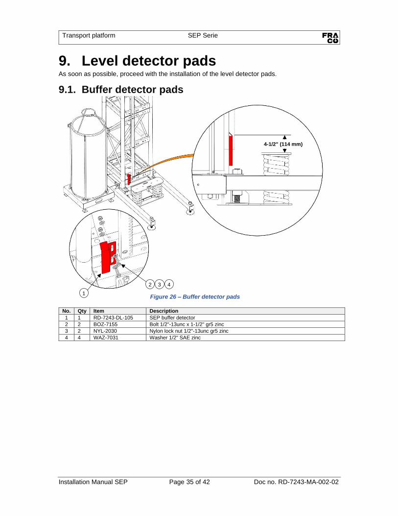
9. Level detector pads As soon as possible, proceed with the installation of the level detector pads.
9.1. Buffer detector pads
No. Qty Item Description
1 1 RD-7243-DL-105 SEP buffer detector
2 2 BOZ-7155 Bolt 1/2"-13unc x 1-1/2" gr5 zinc
3 2 NYL-2030 Nylon lock nut 1/2"-13unc gr5 zinc
4 4 WAZ-7031 Washer 1/2" SAE zinc
4-1/2" (114 mm)
4
3
2
1
Figure 26 – Buffer detector pads
Transport platform SEP Serie
Installation Manual SEP Page 36 of 42 Doc no. RD-7243-MA-002-02
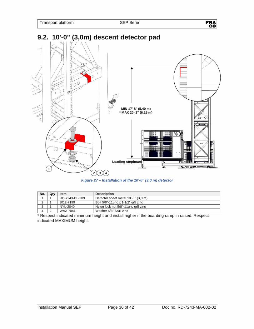
9.2. 10'-0" (3,0m) descent detector pad
* Respect indicated minimum height and install higher if the boarding ramp in raised. Respect
indicated MAXIMUM height.
No. Qty Item Description
1 1 RD-7243-DL-309 Detector sheet metal 10’-0’’ (3,0 m)
2 1 BOZ-7199 Bolt 5/8"-11unc x 1-1/2" gr5 zinc
3 1 NYL-2040 Nylon lock nut 5/8"-11unc gr5 zinc
4 2 WAZ-7041 Washer 5/8" SAE zinc
Figure 27 – Installation of the 10'-0'' (3,0 m) detector
MIN 17'-8" (5,40 m) * MAX 20'-2" (6,15 m)
4
3
2
1
Loading stepboard
Transport platform SEP Serie
Installation Manual SEP Page 37 of 42 Doc no. RD-7243-MA-002-02
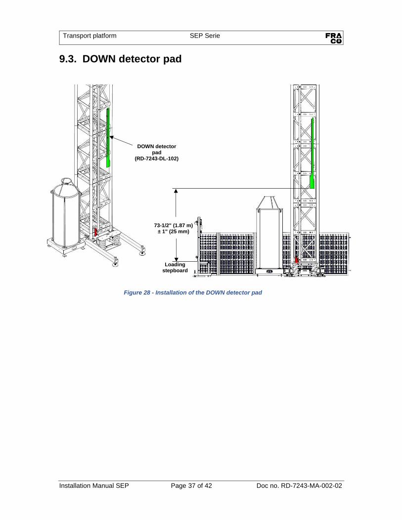
9.3. DOWN detector pad
Figure 28 - Installation of the DOWN detector pad
73-1/2" (1.87 m) ± 1" (25 mm)
DOWN detector pad
(RD-7243-DL-102)
Loading stepboard
Transport platform SEP Serie
Installation Manual SEP Page 38 of 42 Doc no. RD-7243-MA-002-02
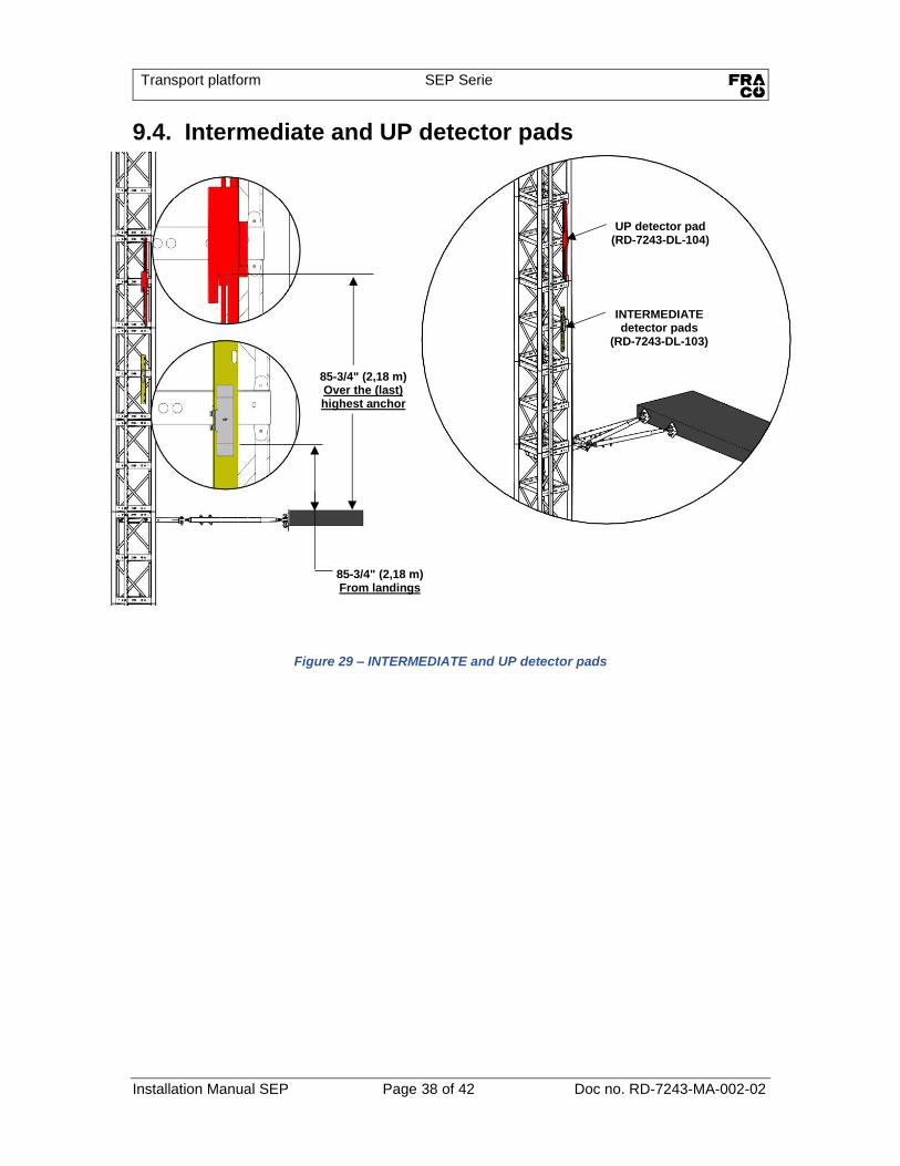
9.4. Intermediate and UP detector pads
85-3/4" (2,18 m) From landings
85-3/4" (2,18 m) Over the (last) highest anchor
UP detector pad (RD-7243-DL-104)
INTERMEDIATE detector pads
(RD-7243-DL-103)
Figure 29 – INTERMEDIATE and UP detector pads

Transport platform SEP Serie
Installation Manual SEP Page 39 of 42 Doc no. RD-7243-MA-002-02
Figure 31 – End travel switches
Figure 30 – Final limit detector HIGH
9.5. End travel switches
Final limit swich (LS15)
Final limit swich (LS15)
HIGH limit switch (LS5)
HIGH limit switch (LS5)
LOW limit switch (LS6)
LOW limit switch (LS6)
Position switch (LS7)
Position switch (LS7)
Final limit detector HIGH
(RD-7243-ME-122)
Mechanical redundancy of the end
for mast inductive detector.
Warning! If you have dismantled this detector during assembly of the frame (SEE SECTION
7.4 INSTALLATION OF THE
PLATFORM (CONTINUED), ON
PAGE 23) do not forget to reinstall it against the rack.
Transport platform SEP Serie
Installation Manual SEP Page 40 of 42 Doc no. RD-7243-MA-002-02
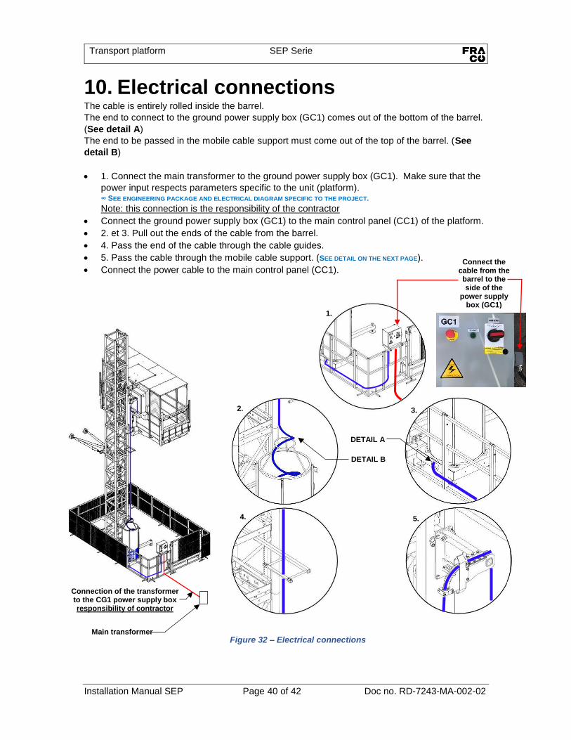
10. Electrical connections The cable is entirely rolled inside the barrel.
The end to connect to the ground power supply box (GC1) comes out of the bottom of the barrel.
(See detail A)
The end to be passed in the mobile cable support must come out of the top of the barrel. (See
detail B)
• 1. Connect the main transformer to the ground power supply box (GC1). Make sure that the
power input respects parameters specific to the unit (platform). ∞ SEE ENGINEERING PACKAGE AND ELECTRICAL DIAGRAM SPECIFIC TO THE PROJECT.
Note: this connection is the responsibility of the contractor
• Connect the ground power supply box (GC1) to the main control panel (CC1) of the platform.
• 2. et 3. Pull out the ends of the cable from the barrel.
• 4. Pass the end of the cable through the cable guides.
• 5. Pass the cable through the mobile cable support. (SEE DETAIL ON THE NEXT PAGE).
• Connect the power cable to the main control panel (CC1).
1.
2.
3.
4.
5.
Figure 32 – Electrical connections
DETAIL B
DETAIL A
Main transformer
Connection of the transformer to the CG1 power supply box responsibility of contractor
Connect the cable from the barrel to the side of the
power supply box (GC1)

Transport platform SEP Serie
Installation Manual SEP Page 41 of 42 Doc no. RD-7243-MA-002-02
Passing the cable through the mobile cable support Push the cable through the mobile cable support and connect to the main control panel CC1.
Tighten the cable in the mobile cable guide.
No. Qty Item Description
1 2 RD-7243-ME-305 Flat bar 0.125" x 1.178" x 3.000" x 11.072"
2 8 BOZ-7050 Bolt 5/16"-18unc x 7/8" gr5 zinc
3 2 BOZ-8634 Bolt 1/4"-20unc x 3" gr5 zinc
4 1 FSQ-0067 Assembled cable support 1-1/2''
5 8 LOZ-5015 Lock washer 5/16" zinc
6 2 NYL-2010 Nylon lock nut 1/4"-20unc gr5 zinc
7 4 WAZ-7011 Washer 1/4" SAE zinc
8 8 WAZ-7017 Washer 5/16" SAE zinc
4
1
2
5
8
7
3
6
Towards the barrel
Towards main control panel
CC1

Transport platform SEP Serie
Installation Manual SEP Page 42 of 42 Doc no. RD-7243-MA-002-02
11. Cable guides Install the cable guides at MAXIMUM intervals of 20'-0" (6,0m) along the mast. The cable guides
must be installed at the center of the mast sections with the open part turned towards the
platform.
No. Qty Item Description
1 1 RD-7243-AT-100 Cable guide
2 2 BOZ-7205 Bolt 5/8"-11unc x 3" gr5 zinc
3 2 NYL-2040 Nylon lock nut 5/8"-11unc gr5 zinc
4 4 WAZ-7041 Washer 5/8" SAE zinc
20'-0" (6,0 m) MAXIMUM
With regards to the barrel
20'-0" (6,0 m) MAXIMUM
1
4
3
2
Figure 33 - Installation of the cable guides
Always install on the center of the mast sections.