transmission: subject: application: chrysler issue date ... · transmission: subject: application:...
TRANSCRIPT
Transmission:Subject:
Application:Issue Date:
RFE SeriesDelay or Double Bump ForwardChryslerOctober, 2015
Technical Bulletin #1705
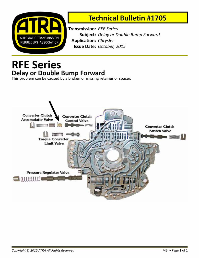
RFE SeriesDelay or Double Bump ForwardThis problem can be caused by a broken or missing retainer or spacer.
MB • Page 1 of 1Copyright © 2015 ATRA All Rights Reserved


Transmission:Subject:
Application:Issue Date:
41TEP1745 Transmission Line Pressure Too HIgh for Too Long After Repair08 Dodge CaravanOctober, 2015
Technical Bulletin #1706
41TEP1745 Transmission Line Pressure Too HighThis DTC is an informational DTC to inform the tech that the transmission has been operating in an open-loop line pressure control for 2000 miles or 1000 2-3 upshifts resulting from a line pressure DTC. The transmission is not designed to operate in open-loop line pressure control for an extended period time. This DTC is intended to protect the transmission. If the DTC sets, the transmission controller will place the transmission into limp-in mode. In order to erase this DTC you must reset (erase) the VLP shift counter and the output tooth counter which is a single procedure under Miscellaneous functions in the scan tool called “Clear Variable Line Pressure (VLP) counters”.
The line pressure sensor (2) is mounted on the top of the valve body, next to the pressure control solenoid (1). The TCM utilizes a closed-loop system to control transmission ine pressure. The system contains a variable force style solenoid, the Pressure Control Solenoid. The solenoid is duty cycle con-trolled by the TCM to vent the unnecessary line pressure supplied by the oil pump back to the sump. The system also contains a variable pressure style sensor, the Line Pressure Sensor, which is a direct in-put to the TCM. The line pressure solenoid monitors the transmission line pressure and completes the feedback loop to the TCM. The TCM uses this information to adjust its control of the pressure control solenoid to achieve the desired line pressure.
MB • Page 1 of 2Copyright © 2015 ATRA All Rights Reserved

MB • Page 2 of 2 Copyright © 2015 ATRA All Rights Reserved
#170641TEP1745 Transmission Line Pressure Too High
1
2

Transmission:Subject:
Application:Issue Date:
6L SeriesErratic TCC Operation, Harsh TCC Apply, Excessive TCC Slip, Harsh ShiftsGMOctober, 2015
Technical Bulletin #1707
6L SeriesErratic TCC Operation, Harsh TCC Apply, Excessive TCC SlipWhile working on a GM vehicle equipped with a 6L series transmission, you may encounter erratic TCC operation, harsh TCC apply, excessive TCC slip, harsh shifts, overheated fluid, codes 218 (over-temp), 741 (TCC off) & 742 (TCC stuck on) may set. These concerns may be caused by a worn TCC control valve located in the pump.
PH • Page 1 of 1Copyright © 2015 ATRA All Rights Reserved

Transmission:Subject:
Application:Issue Date:
722.6N3/N2 ID & Sensor FunctionChrysler/MercedesOctober, 2015
Technical Bulletin #1708
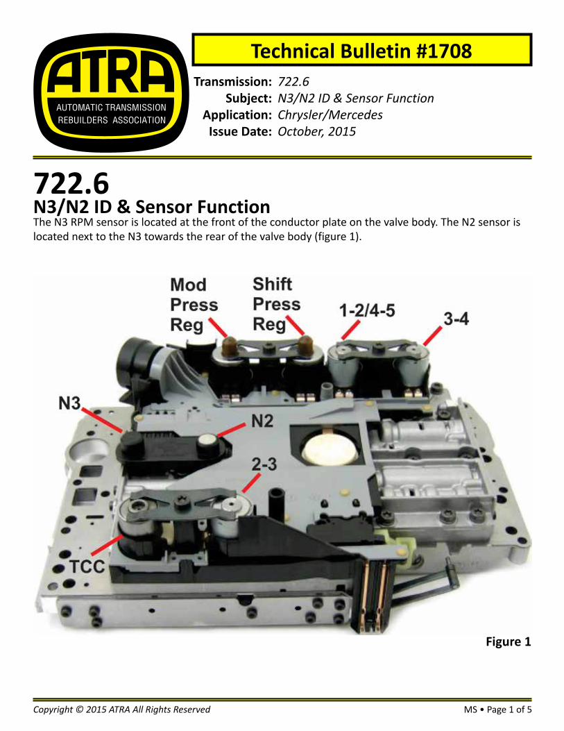
722.6N3/N2 ID & Sensor FunctionThe N3 RPM sensor is located at the front of the conductor plate on the valve body. The N2 sensor is located next to the N3 towards the rear of the valve body (figure 1).
Figure 1
MS • Page 1 of 5Copyright © 2015 ATRA All Rights Reserved

MS • Page 2 of 5 Copyright © 2015 ATRA All Rights Reserved
#1708The N3 and N2 RPM sensors are both Hall Effect type sensors. They are supplied 4-8 volts and grounded by the TCM. The RPM sensor signal is a pulsed square wave (DC Hz) to the TCM. The approximate resistance of both sensors is 4.5 ohms (figure 2) see chart below.
1: N3 RPM sensor signal (pulsed voltage)2: Modulated Pressure Regulator solenoid (Y3/6y1) (5.5 Ω)3: N3 RPM sensor signal (pulsed voltage)4: ATF Temperature sensor / Starter Lock-Out 5: Not Used6: Solenoid supply voltage (system voltage)7: RPM sensor supply voltage (4-8 volts)8: 2-3 Shift solenoid (Y3/6y5) (4.5 Ω)9: 3-4 Shift solenoid (Y3/6y4) (4.5 Ω)10: Shift Pressure Regulator solenoid (Y3/6y2) (5.5 Ω)11: PWM TCC solenoid (Y3/6y6) (2.7 Ω)12: Sensor ground (0.1 volts or less)13: 1-2/4-5 Shift solenoid (Y3/6y3) (4.5 Ω)
722.6N3/N2 ID & Sensor Function
Figure 2

MS • Page 3 of 5Copyright © 2015 ATRA All Rights Reserved
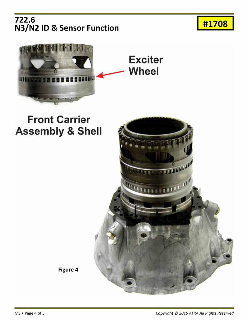
#1708The N3 sensor reads the exciter wheel on the K1 Clutch Drum which contains the F1 Sprag and the B1 Clutch Hub (figure 3). The N2 sensor reads the exciter wheel on the Front Carrier assembly and Shell that rotates around the Front Sun Gear (figure 4). The Front Sun Gear is part of the K1 Drum.
722.6N3/N2 ID & Sensor Function
Figure 3
MS • Page 4 of 5 Copyright © 2015 ATRA All Rights Reserved
#1708722.6N3/N2 ID & Sensor Function
Figure 4
MS • Page 5 of 5Copyright © 2015 ATRA All Rights Reserved
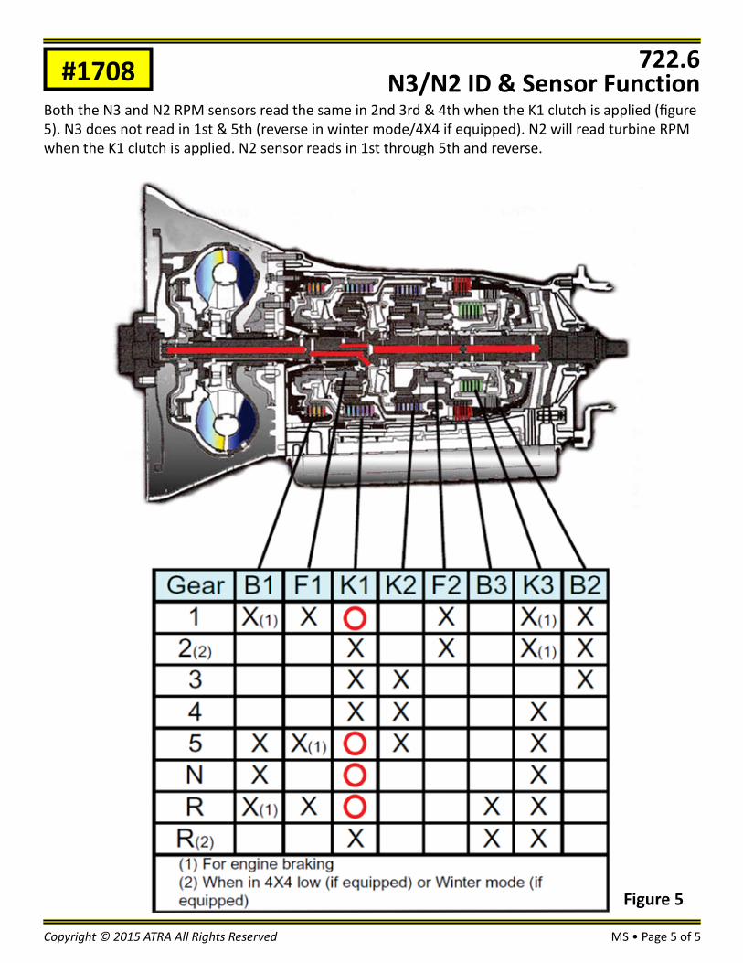
#1708Both the N3 and N2 RPM sensors read the same in 2nd 3rd & 4th when the K1 clutch is applied (figure 5). N3 does not read in 1st & 5th (reverse in winter mode/4X4 if equipped). N2 will read turbine RPM when the K1 clutch is applied. N2 sensor reads in 1st through 5th and reverse.
722.6N3/N2 ID & Sensor Function
Figure 5


Transmission:Subject:
Application:Issue Date:
BVGAOne-Way ClutchHondaOctober, 2015
Technical Bulletin #1709
Honda BVGAOne-Way ClutchWhen checking the one way clutch on a BVGA unit on a Honda Transmission mounted on a Pilot; you can either hold hub A or gear B. Hub C should turn freely in the direction of the arrow shown. Also always make sure it locks in the opposite direction.
RA • Page 1 of 1Copyright © 2015 ATRA All Rights Reserved
