transmission removal
TRANSCRIPT

MAG-00601 GM CORVETTE 1955-1962 (C1) TKO Installation Manual, Rev A 05/27/14
CORVETTE 1955-1962
TKO 5-SPEED MANUAL TO MANUAL
TRANSMISSION CONVERSION INSTALLATION MANUAL
2 MAG-00601 GM CORVETTE 1955-1962 (C1) TKO Installation Manual, Rev A 05/27/14
FOLLOW FACTORY SERVICE MANUAL (FSM) RECOMMENDED SAFETY PRECAUTIONS. TRANSMISSION REMOVAL AND INSTALLATION IS A LABOR INTENSIVE JOB, WHICH CAN RESULT IN SERIOUS INJURY OR DEATH IF CAUTION IS NOT TAKEN. PLEASE BE CAREFUL PERFORMING THIS JOB, OR HAVE A PROFESSIONAL PERFORM THE JOB FOR YOU. REFER TO FACTORY SERVICE MANUAL (FSM) FOR ADDITIONAL DETAILS OF THE PROCEDURES BELOW, AS REQUIRED.
FOR BOLT TORQUE SPECIFICATIONS, REFER TO YOUR FACTORY SERVICE MANUAL.
The material herein is the intellectual property of Silver Sport Transmissions (“SST”) and is to be used by SST customers or their authorized installers for the sole purpose of installing SST-supplied transmissions and related parts. Under no circumstances shall the manual or any portion thereof be copied,
duplicated, distributed or incorporated in any written or printed document without the express written approval of Silver Sport Transmissions.
Before you start:
Test drive the vehicle, if possible, before you begin. Pay attention to noise and vibration and record your observations. At the end of the installation, perform another test drive to compare.
In addition to this manual, you should have received instructions for checking your bellhousing runout. The bellhousing runout must be checked (and corrected if necessary) for Tremec’s warranty coverage.
You should also verify the parts you received. Compare the received items to the detailed invoice provided in your shipment.
PLEASE READ ALL INSTRUCTIONS BEFORE INSTALLATION In addition to these instructions, you should receive the following instructions based on your order, if applicable:
1. All kits –MAA-00101 Inspection and Correction of Bellhousing to Crankshaft Runout 2. Hydraulic throw out bearing kit – MAG-00402 Hydraulic Kit Instructions for GM 3. MAA-00201 – Automatic to Manual conversion, General Guidelines
Your invoice lists the individual hardware packs and where they are used.
NOTE: Transmission must be test shifted before installation. Due to jostling during shipping, some transmissions will not shift properly when removed from the box. Please make sure that the gear
selector will move into each of the six possible positions while rotating the input shaft and checking for output shaft rotation. The rubber sleeve may need to be removed from the output shaft to allow it
to turn easier (see photo on page 5). If the input shaft will not turn, slide the clutch disc over the input shaft and jerk the clutch disc left and right to break it free. If this does not correct the issue,
call Silver Sport Transmissions at 865-609-8187 extension 118 for instructions.
THIS CANNOT BE CORRECTED WITH THE TRANSMISSION INSTALLED IN THE CAR!
TEST SHIFT FIRST!
3 MAG-00601 GM CORVETTE 1955-1962 (C1) TKO Installation Manual, Rev A 05/27/14
A. REMOVE EXISTING EQUIPMENT
1. Disconnect negative (-) battery cable. 2. Remove console top plate. Disconnect power window switch connector, if equipped (note
orientation of connection). Remove power window switch heat shield cup and switch, if equipped. 3. Remove shifter knob & boot. Place shifter in neutral. 4. Remove breather assembly & ignition cluster cover/distributor cap from engine. The fan shroud
may need to be loosened as fan blades may contact it as the engine is lowered in the back during transmission removal.
5. Disconnect tachometer drive from distributor, if equipped. 6. Disconnect throttle linkage at carburetor. 7. Raise car securely on lift or jack stands. 6 ton jack stands will allow you to raise the car higher than
3 ton jack stands will, which makes the installation easier. 8. Loosen exhaust pipes at manifold and remove as required for working clearance and to allow the
engine to tilt rearward. 9. Unbolt starter and set aside. 10. Disconnect clutch fork pushrod from the clutch fork. 11. Remove bellhousing dust cover. 12. Remove driveshaft. 13. Remove shifter assembly. 14. Remove speedometer cable. 15. Secure rear of engine with hydraulic jack. 16. Remove transmission crossmember. 17. Secure transmission (jack recommended) and unbolt from bellhousing, then move rearward in
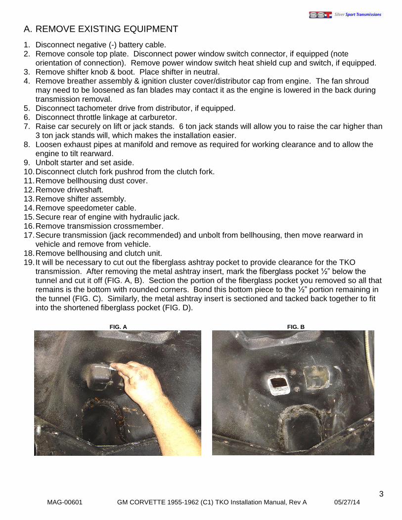
vehicle and remove from vehicle. 18. Remove bellhousing and clutch unit. 19. It will be necessary to cut out the fiberglass ashtray pocket to provide clearance for the TKO
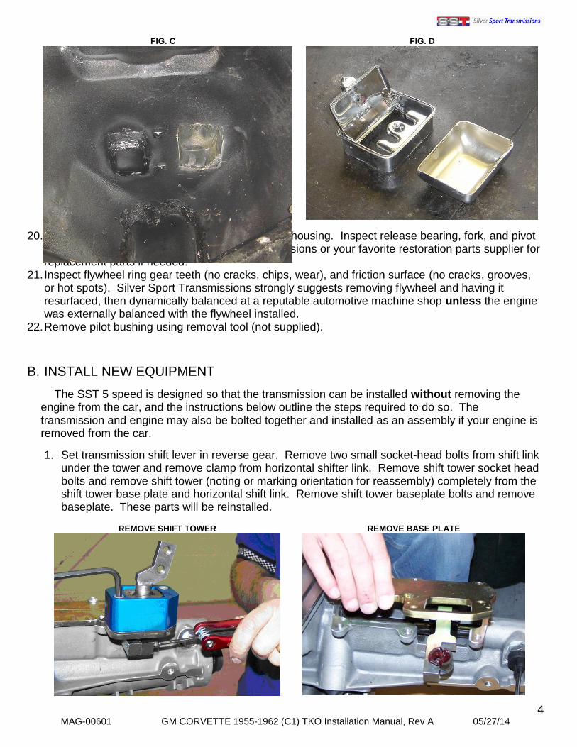
transmission. After removing the metal ashtray insert, mark the fiberglass pocket ½” below the tunnel and cut it off (FIG. A, B). Section the portion of the fiberglass pocket you removed so all that remains is the bottom with rounded corners. Bond this bottom piece to the ½” portion remaining in the tunnel (FIG. C). Similarly, the metal ashtray insert is sectioned and tacked back together to fit into the shortened fiberglass pocket (FIG. D).
FIG. B
FIG. A
4 MAG-00601 GM CORVETTE 1955-1962 (C1) TKO Installation Manual, Rev A 05/27/14
20. Remove clutch fork and release bearing from bellhousing. Inspect release bearing, fork, and pivot
ball stud for wear. Contact Silver Sport Transmissions or your favorite restoration parts supplier for replacement parts if needed.
21. Inspect flywheel ring gear teeth (no cracks, chips, wear), and friction surface (no cracks, grooves, or hot spots). Silver Sport Transmissions strongly suggests removing flywheel and having it resurfaced, then dynamically balanced at a reputable automotive machine shop unless the engine was externally balanced with the flywheel installed.
22. Remove pilot bushing using removal tool (not supplied).
B. INSTALL NEW EQUIPMENT
The SST 5 speed is designed so that the transmission can be installed without removing the engine from the car, and the instructions below outline the steps required to do so. The transmission and engine may also be bolted together and installed as an assembly if your engine is removed from the car.
1. Set transmission shift lever in reverse gear. Remove two small socket-head bolts from shift link under the tower and remove clamp from horizontal shifter link. Remove shift tower socket head bolts and remove shift tower (noting or marking orientation for reassembly) completely from the shift tower base plate and horizontal shift link. Remove shift tower baseplate bolts and remove baseplate. These parts will be reinstalled.
REMOVE SHIFT TOWER
REMOVE BASE PLATE
FIG. C
FIG. D
5 MAG-00601 GM CORVETTE 1955-1962 (C1) TKO Installation Manual, Rev A 05/27/14
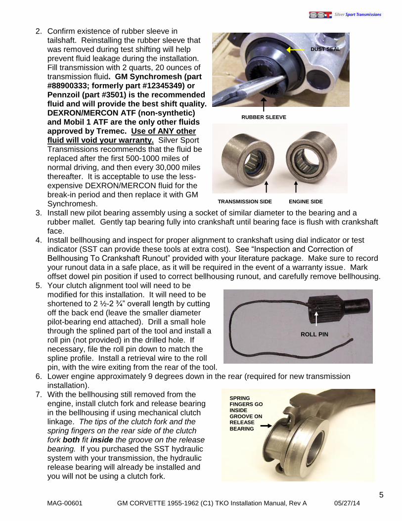
2. Confirm existence of rubber sleeve in tailshaft. Reinstalling the rubber sleeve that was removed during test shifting will help prevent fluid leakage during the installation. Fill transmission with 2 quarts, 20 ounces of transmission fluid. GM Synchromesh (part #88900333; formerly part #12345349) or Pennzoil (part #3501) is the recommended fluid and will provide the best shift quality. DEXRON/MERCON ATF (non-synthetic) and Mobil 1 ATF are the only other fluids approved by Tremec. Use of ANY other fluid will void your warranty. Silver Sport Transmissions recommends that the fluid be replaced after the first 500-1000 miles of normal driving, and then every 30,000 miles thereafter. It is acceptable to use the less-expensive DEXRON/MERCON fluid for the break-in period and then replace it with GM Synchromesh.
3. Install new pilot bearing assembly using a socket of similar diameter to the bearing and a rubber mallet. Gently tap bearing fully into crankshaft until bearing face is flush with crankshaft face.
4. Install bellhousing and inspect for proper alignment to crankshaft using dial indicator or test indicator (SST can provide these tools at extra cost). See “Inspection and Correction of Bellhousing To Crankshaft Runout” provided with your literature package. Make sure to record your runout data in a safe place, as it will be required in the event of a warranty issue. Mark offset dowel pin position if used to correct bellhousing runout, and carefully remove bellhousing.
5. Your clutch alignment tool will need to be modified for this installation. It will need to be shortened to 2 ½-2 ¾” overall length by cutting off the back end (leave the smaller diameter pilot-bearing end attached). Drill a small hole through the splined part of the tool and install a roll pin (not provided) in the drilled hole. If necessary, file the roll pin down to match the spline profile. Install a retrieval wire to the roll pin, with the wire exiting from the rear of the tool.
6. Lower engine approximately 9 degrees down in the rear (required for new transmission installation).
7. With the bellhousing still removed from the engine, install clutch fork and release bearing in the bellhousing if using mechanical clutch linkage. The tips of the clutch fork and the spring fingers on the rear side of the clutch fork both fit inside the groove on the release bearing. If you purchased the SST hydraulic system with your transmission, the hydraulic release bearing will already be installed and you will not be using a clutch fork.
TRANSMISSION SIDE ENGINE SIDE
DUST SEAL
RUBBER SLEEVE
ROLL PIN
SPRING FINGERS GO INSIDE GROOVE ON RELEASE
BEARING

6 MAG-00601 GM CORVETTE 1955-1962 (C1) TKO Installation Manual, Rev A 05/27/14
8. Set transmission into tunnel, sliding rearward until rear of case stops against the x-frame.
Transmission tailhousing should be centered in the tunnel, while the front should be angled towards the passenger side to facilitate installation of the bellhousing. Transmission input shaft should be pointed downwards as far as possible to provide clearance for the bellhousing.
9. With the input shaft pointed down as far as possible, slide the bellhousing over the input shaft and up against the transmission case. The bellhousing may need to be upside down while being slid into place.
10. Insert pressure plate into bellhousing over input shaft. This may also be easier with the
bellhousing upside down. 11. Orient the bellhousing so it is right side up. Loosely install one transmission to bellhousing bolt.
Do not tighten. This will keep the bellhousing secured during the next step. 12. Raise transmission nose enough to insert clutch disc into bellhousing against flywheel and fully
insert modified alignment tool through clutch disc and into pilot bearing. Raise transmission as required to allow pressure plate to be brought forward for assembly on the flywheel. It may be necessary to remove the transmission-to-bellhousing bolt in order to fit your hand in the bellhousing and move the pressure plate at the same time. Begin installing pressure plate bolts, using flywheel spanner tool to rotate engine counter clockwise (facing flywheel) to access each of the six clutch plate bolts. Install each one only finger tight on the first round, then incrementally tighten each one in an alternating sequence until all six are snug. Then tighten each one in the same alternating sequence to 35 lb.-ft.
CLUTCH DISC
PRESSURE PLATE
ALIGNMENT TOOL
CLUTCH FORK SHOULD ALREADY BE INSTALLED AT THIS POINT, REMOVED FOR CLARITY IN PHOTO

7 MAG-00601 GM CORVETTE 1955-1962 (C1) TKO Installation Manual, Rev A 05/27/14
13. Lower the nose of the transmission enough to remove alignment tool using retrieval wire. 14. Begin raising transmission. As needed, raise engine up to permit attaching the bellhousing to
the engine. 15. Remove transmission to bellhousing securing bolt if not already removed, and attach
bellhousing to engine. Ensure that there are no hoses, cables, or wires caught between the bellhousing and engine block.
16. Move the transmission further forward, inserting the input shaft into the clutch disc and pilot bearing. Due to the tight clearance around the upper right transmission to bellhousing bolt, a socket head bolt can be substituted for the hex head bolt if you do not have a suitable hex head wrench. Use caution while engaging transmission input shaft into clutch disc and pilot bearing. Do not allow weight of transmission to rest on assembly until fully engaged (doing so can misalign disc or damage pilot bearing). The rubber sleeve may be temporarily removed from the output shaft, and the slip yoke inserted and the output shaft rotated, as required, to facilitate engagement into clutch disk. DO NOT use the transmission to bellhousing bolts to draw the transmission up to the bellhousing! Once the transmission is fully seated by hand against bellhousing, fasten with ½” x 1-3/4” bolts and washers provided (HWG-PACK A). Torque to 50 - 60 lb.-ft.
17. While the transmission tailhousing is sitting directly on the x-frame, re-install shifter baseplate
and bolts. Tighten to 20 lb.-ft. Re-install shift tower using two (2) socket head cap screws. Re-install the horizontal shifter link clamp and bolts.
18. Install shifter dust cover using two small screws provided and seal around the cover and the vertical seams with RTV silicone (not supplied).
19. Raise up engine/transmission until it rests firmly against floor pan. 20. Attach rubber isolator mount loosely to the transmission M10-1.5 x 30 bolts and lock washers
(HWG-PACK H). Install crossmember to x-frame using the original hardware you removed
NOTE: Photos above show the transmission installed in a 1965 model. Your shift mechanism and dust cover
will be very similar to the one above.
NOTE: If the transmission stops approximately ½ inch away from seating fully against the bellhousing, install and finger-tighten bellhousing to transmission bolts. Connect clutch linkage and depress pedal lightly while pushing transmission forward to facilitate alignment of clutch disk to input shaft and pilot bearing. DO NOT force
the transmission into engagement – damage to the pilot bearing may result. Tighten bellhousing to engine bolts once the transmission is seated against the bellhousing.
8 MAG-00601 GM CORVETTE 1955-1962 (C1) TKO Installation Manual, Rev A 05/27/14
earlier. Lower transmission onto crossmember. Place 3 ¼” x 1 ½” flat reinforcement plate (supplied) under crossmember, and attach isolator mount to crossmember by passing the bolts from hardware pack HWG-PACK B through the reinforcement plate and crossmember, and into the isolator mount. Tighten all mount and crossmember fasteners.
21. Confirm no interference to car body exists or noise will occur as the driveline moves under load. If tunnel contact exists, check for deteriorated body isolating strips or bushings. Failure to correct body bushing problems can result in transmission contact with the body, which will cause a gear-like “rattle” or “clunking” that is not associated with the gearbox internals, particularly when driving in the higher gears.
22. Confirm transmission is centered in floor tunnel. If the shifter tower is located less than 1/8” from either edge of the shifter hole, slot the holes in the transmission crossmember, as required, to provide the required clearance for the tower in the shifter hole. Cutting of the shifter hole is not required and should not be done. Please contact Silver Sport Transmissions if you need more information or support regarding this portion of the installation.
23. Remove the rubber sleeve from the output shaft (see step B-2 and photo on pg. 5). 24. Mark slip yoke to driveshaft orientation with a paint marker. Remove slip yoke from new
driveshaft, and insert slip yoke fully into the tailhousing, until the shoulder on the slip yoke is touching the rubber dust seal. Set driveshaft into place rear-end first, and seat u-joints into differential yoke. Install rear straps and torque to factory specs. Make certain all parts are clean and properly assembled. Double check your assembly. Assemble driveshaft to front yoke, making sure that the alignment marks line up. Assembling the slip yoke to the driveshaft improperly will cause a vibration. Again, make certain all parts are clean and properly assembled.
25. Reinstall bellhousing inspection cover and starter. 26. Connect clutch linkage - do not preload mechanical release bearing. Adjust linkage as required.
If using a SST hydraulic system (available separately), follow instructions provided. 27. Wrap tape around speedometer cable ends to
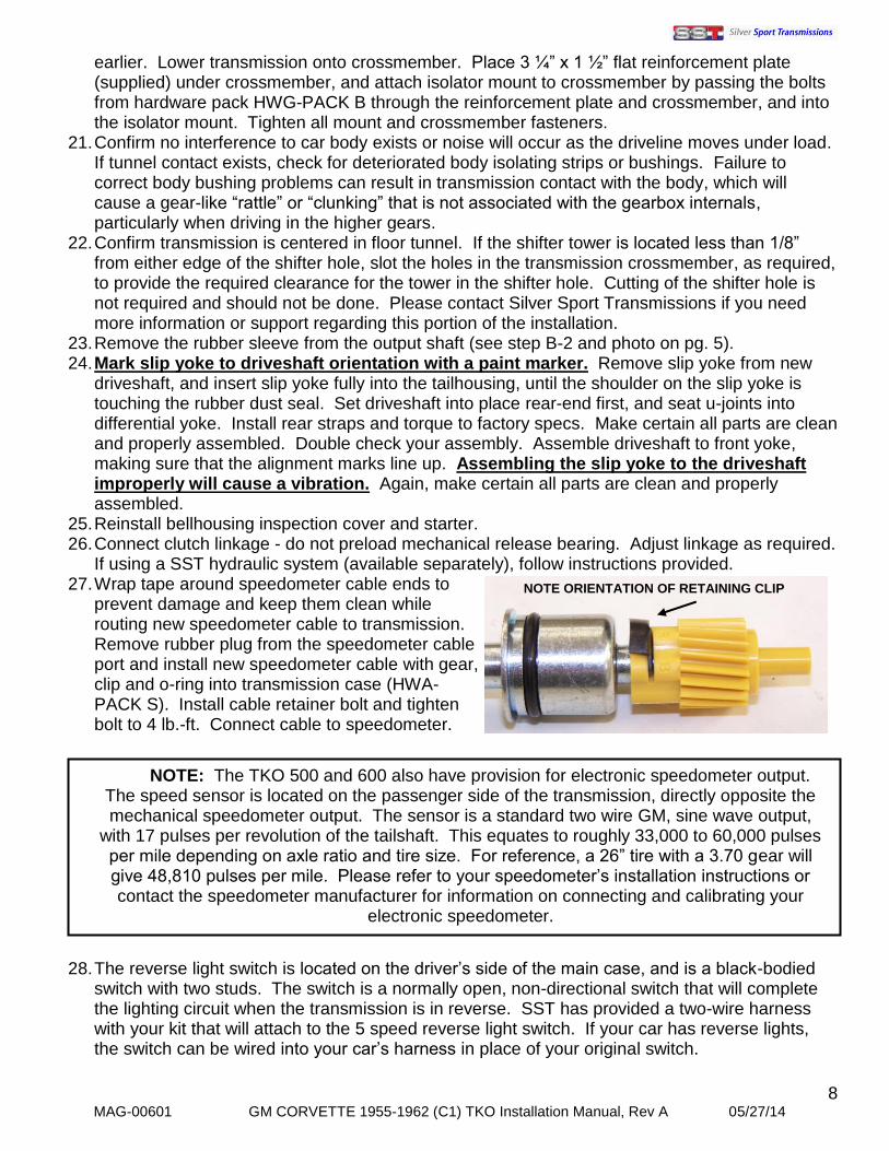
prevent damage and keep them clean while routing new speedometer cable to transmission. Remove rubber plug from the speedometer cable port and install new speedometer cable with gear, clip and o-ring into transmission case (HWA- PACK S). Install cable retainer bolt and tighten bolt to 4 lb.-ft. Connect cable to speedometer.
28. The reverse light switch is located on the driver’s side of the main case, and is a black-bodied
switch with two studs. The switch is a normally open, non-directional switch that will complete the lighting circuit when the transmission is in reverse. SST has provided a two-wire harness with your kit that will attach to the 5 speed reverse light switch. If your car has reverse lights, the switch can be wired into your car’s harness in place of your original switch.
NOTE: The TKO 500 and 600 also have provision for electronic speedometer output. The speed sensor is located on the passenger side of the transmission, directly opposite the mechanical speedometer output. The sensor is a standard two wire GM, sine wave output,
with 17 pulses per revolution of the tailshaft. This equates to roughly 33,000 to 60,000 pulses per mile depending on axle ratio and tire size. For reference, a 26” tire with a 3.70 gear will give 48,810 pulses per mile. Please refer to your speedometer’s installation instructions or contact the speedometer manufacturer for information on connecting and calibrating your
electronic speedometer.
NOTE ORIENTATION OF RETAINING CLIP
9 MAG-00601 GM CORVETTE 1955-1962 (C1) TKO Installation Manual, Rev A 05/27/14
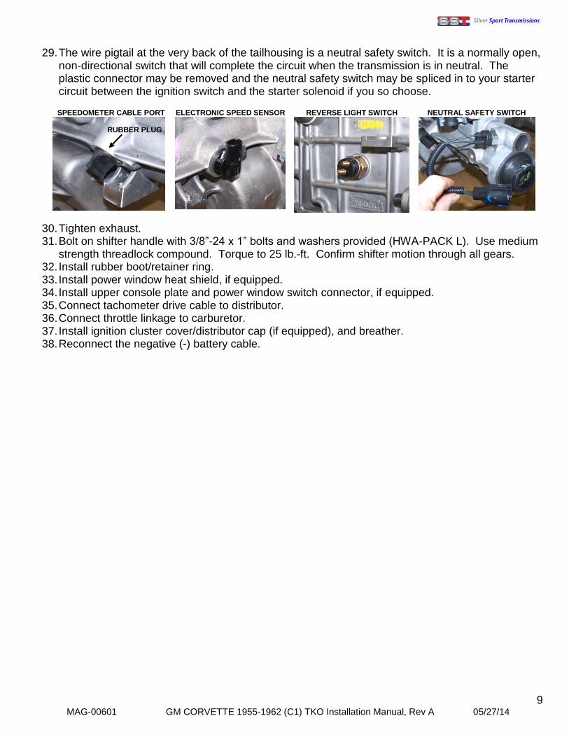
29. The wire pigtail at the very back of the tailhousing is a neutral safety switch. It is a normally open,
non-directional switch that will complete the circuit when the transmission is in neutral. The plastic connector may be removed and the neutral safety switch may be spliced in to your starter circuit between the ignition switch and the starter solenoid if you so choose.
30. Tighten exhaust. 31. Bolt on shifter handle with 3/8”-24 x 1” bolts and washers provided (HWA-PACK L). Use medium
strength threadlock compound. Torque to 25 lb.-ft. Confirm shifter motion through all gears. 32. Install rubber boot/retainer ring. 33. Install power window heat shield, if equipped. 34. Install upper console plate and power window switch connector, if equipped. 35. Connect tachometer drive cable to distributor. 36. Connect throttle linkage to carburetor. 37. Install ignition cluster cover/distributor cap (if equipped), and breather. 38. Reconnect the negative (-) battery cable.
REVERSE LIGHT SWITCH
SPEEDOMETER CABLE PORT
NEUTRAL SAFETY SWITCH
ELECTRONIC SPEED SENSOR
RUBBER PLUG
10 MAG-00601 GM CORVETTE 1955-1962 (C1) TKO Installation Manual, Rev A 05/27/14
FINAL INSTALLATION STEPS
1. If you did not fill the transmission with fluid before installation, remove the fill plug on the passenger’s side of the transmission and fill with 2 quarts, 20 ounces of transmission fluid, or until fluid runs out of the fill hole with the vehicle level. GM Synchromesh (part #88900333; formerly Part #12345349) or Pennzoil (part #3501) is the recommended fluid and will provide the best shift quality. DEXRON/MERCON ATF (non-synthetic) and Mobil 1 ATF are the only other fluids approved by Tremec. Use of ANY other fluid will void your warranty. Silver Sport Transmissions recommends that the fluid be replaced after the first 500-1000 miles of normal driving, and then every 30,000 miles thereafter. It is acceptable to use the less-expensive DEXRON/MERCON fluid for the break-in period and then replace it with GM Synchromesh. Reinstall the fill plug after adding fluid.
2. Start engine and allow engine to idle for a few minutes. 3. Check for leaks while warming up. 4. Slowly rev engine in neutral and listen for any unusual sounds or vibration. 5. Shift through all forward gears with the clutch disengaged (clutch pedal depressed). 6. Do not shift into reverse above idle speed, reverse is not synchronized. Shifting into reverse may
require shifting into a forward gear first to prevent grinding. 7. Test drive at low speeds and low RPM. 8. Gradually increase engine RPM and vehicle speed. 9. Compare this test drive to the pre-installation test drive. 10. Drive conservatively for the first 500-1000 miles for transmission break-in. 11. If you experience vibration at highway speeds, verify that there is no body contact with the new
transmission. If there is no contact, it may be necessary to adjust your driveline angle. Much has been written about driveline angles and how to determine them, and there is a lot of great information available online from multiple websites. If you need further help with your driveline angle, call Silver Sport Transmissions’ Customer Service at 865-609-8187 extension 118.
11 MAG-00601 GM CORVETTE 1955-1962 (C1) TKO Installation Manual, Rev A 05/27/14
SPECIFICATIONS AND MAINTENANCE
GM Synchromesh (part #88900333; formerly part #12345349) or Pennzoil (part #3501) is the recommended fluid and will provide the best shift quality. DEXRON/MERCON ATF (non-synthetic) and Mobil 1 ATF are the only other fluids approved by Tremec. Use of ANY other fluid will void your warranty. Silver Sport Transmissions recommends that the fluid be replaced after the first 500-1000 miles of normal driving, and then every 30,000 miles thereafter. It is acceptable to use the less-expensive DEXRON/MERCON fluid for the break-in period and then replace it with GM Synchromesh.
FLUID CAPACITY: 2 QUARTS, 20 OUNCES (U.S.)
DO NOT EXCEED MAXIMUM INPUT TORQUE:
TKO 500: 500 lb.-ft. in 4th gear
TKO 600: 600 lb.-ft. in 4th gear GEAR RATIOS:
o TKO 500 1ST 3.27 2ND 1.98 3RD 1.34 4TH 1.00 5TH 0.68
o TKO 600
1ST 2.87 2ND 1.89 3RD 1.28 4TH 1.00 5TH 0.64 (0.82 OPTIONAL)
CONTACT INFORMATION
SILVER SPORT TRANSMISSIONS 2250 STOCK CREEK BOULEVARD
ROCKFORD, TENNESSEE 37853-3043 Phone: (865) 609-8187
Toll Free: (888) 609-0094 Fax: (865) 609-8287
SALES EXTENSION: 113
CUSTOMER SERVICE AND TECH SUPPORT EXTENSION: 118
WWW.SHIFTSST.COM
SILVER SPORT TRANSMISSIONS IS DEDICATED TO
YOUR SATISFACTION AND ENJOYMENT OF THIS PRODUCT. PLEASE SEND US PICTURES OF YOUR CAR ALONG WITH A TESTIMONIAL OF HOW YOU RATE THIS PRODUCT. WE WILL BE POSTING MANY CUSTOMER
FEEDBACK LETTERS AND PICTURES ON OUR WEBSITE AND BROCHURES.
ENJOY YOUR SILVER SPORT TRANSMISSION SYSTEM!