transmission line fault location in mmc-hvdc grids based
TRANSCRIPT

1728 IEEE INTERNET OF THINGS JOURNAL, VOL. 8, NO. 3, FEBRUARY 1, 2021
ViPSN: A Vibration-Powered IoT PlatformXin Li , Graduate Student Member, IEEE, Li Teng, Graduate Student Member, IEEE,
Hong Tang, Student Member, IEEE, Jingying Chen, Haoyu Wang , Senior Member, IEEE,
Yu Liu, Member, IEEE, Minfan Fu , Senior Member, IEEE, and Junrui Liang , Member, IEEE
Abstract—In this article, we introduce a vibration-poweredsensing node (ViPSN), a programmable Internet-of-Things (IoT)platform for the development of vibration-powered or motion-powered sensing and transmitting systems. It leverages theexploitation and utilization of ambient vibration energy by usinga piezoelectric transducer. The roles and relations of six nec-essary modules, including energy generation unit (EGU), energytransduction unit (ETU), energy enhancement unit (EEU), energymanagement unit (EMU), energy user unit (EUU), and edgedemonstration unit (EDU) are discussed in detail. In particular,an enhanced EMU is proposed by making necessary complementsto an extensively used off-the-shelf integrated circuit (IC) solutionfor piezoelectric transducers. It provides more comprehensiveenergy storage indicating signals, such that the sensing, comput-ing, and transmitting tasks can be carried out more robustly bykeeping a good awareness of the remaining energy. Owing tothe enhanced EMU design, vibration energy in various forms,such as intermittent and transient ones, can be more effectivelyharvested and utilized. The performance of ViPSN is evaluated,in terms of its lifetime and Quality of Service (QoS), under dif-ferent vibration scenarios. The inclusive design and affiliatedopensource project of ViPSN help build a new ecosystem for theresearch and development of vibration- or motion-powered IoTsystems.
Index Terms—Battery-free system, energy management,kinetic energy harvesting, piezoelectric transducer, wireless sen-sor network.
I. INTRODUCTION
OVER the last decades, researchers have worked towardthe realization of the Internet of Everything by deploying
long-lasting, low-cost, environmental-friendly, and sustainablesensing nodes. They have continually redecorated and refined
Manuscript received May 30, 2020; revised June 25, 2020 and July 23,2020; accepted July 31, 2020. Date of publication August 17, 2020; date ofcurrent version January 22, 2021. This work was supported in part by theNational Natural Science Foundation of China under Grant 61401277; in partby ShanghaiTech University under Grant F-0203-13-003; and in part by theShanghai Key Laboratory of Mechanics in Energy Engineering under GrantORF-202001. (Corresponding author: Junrui Liang.)
Xin Li is with the Center for Intelligent Power and Energy Systems andthe School of Information Science and Technology, ShanghaiTech University,Shanghai 201210, China, also with the Shanghai Institute of Microsystem andInformation Technology, Chinese Academy of Sciences, Shanghai 200050,China, and also with the University of Chinese Academy of Sciences, Beijing100049, China.
Li Teng, Hong Tang, Jingying Chen, Haoyu Wang, Yu Liu, Minfan Fu, andJunrui Liang are with the Center for Intelligent Power and Energy Systemsand the School of Information Science and Technology, ShanghaiTechUniversity, Shanghai 201210, China (e-mail: [email protected];[email protected]; [email protected]; [email protected]; [email protected]; [email protected];[email protected]).
Digital Object Identifier 10.1109/JIOT.2020.3016993
this shared vision by creating new terms, such as “ubiquitoussensing,” “smart dust,” “TerraSwarm,” and the most recent“Internet of Things (IoT)” [1]. However, the state-of-the-artbattery-powered IoT sensing nodes are incapable of dispersedand everlasting deployments. Especially, in some applications,such as smart building and environmental monitoring, the laborcost for replacing or recharging batteries is too high to enableall the things with sensory ability [2], [3]. The battery-freesolution is necessary and the only option for extensive andeverlasting deployment of smart sensor networks. The energyharvesting (EH) technologies provide the feasibility of self-contained and self-powered IoT nodes by scavenging energyin different physical forms from the environment.
Compared with sensors powered by solar and radiofrequency (RF), the deployment of vibration-powered sen-sors is not limited by illumination or RF signal intensity. Itcan be applied to any place where vibrations, or more gen-erally speaking, mechanical movements, exist. For example,the vibration-powered sensors can be deployed in large infras-tructures, which undergo vibrations, or other moving objectssuch as vehicles, human, or animal bodies. It was reportedthat walking could generate approximately 120–270 μWpower [4]; writing, spinning in a swivel chair, or opening adrawer can provide 10–15 μW power [5]. Therefore, vibra-tion EH (VEH) can serve as a complementary power solutionin these scenarios, where illumination is poor (unsuitable forthe solar harvester), RF signal is weak (unsuitable for theRF energy harvester), and the temperature difference is notsignificant (unsuitable for the thermoelectric energy harvester).
Challenges: The features of different sources have a lot todo with the energy harvester design and optimization. Thereare several challenges for implementing the vibration-poweredIoT systems. For example, most vibration energy is sparselydistributed, which is not convenient for centralized utilization.The level of available vibration power is low, much lowerthan that of the grid power. Moreover, ambient vibrations areusually broadband. Some vibrations occur in an intermittentmode, while some others might occur in a transient mode.In general, the design and optimization of vibration-poweredIoT systems require a joint effort from many related disci-plines, such as mechanical engineering, electrical engineering,computer engineering, and material science.
Motivation: Although the energy density of ambient vibra-tion (about 200 μW/cm2) is larger than that of ambient RFwaves (about 0.0002–1 μW/cm2) [6], compared with the for-merly proposed RF-powered devices, such as RF-poweredcamera [7], [8], the vibration-powered IoT applications are
2327-4662 c© 2020 IEEE. Personal use is permitted, but republication/redistribution requires IEEE permission.See https://www.ieee.org/publications/rights/index.html for more information.

LI et al.: ViPSN: VIBRATION-POWERED IoT PLATFORM 1729
(a) (b) (c)
Fig. 1. ViPSN prototype including six modules. (a) System assembly.(b) Module breakdown. (c) EDU.
less mature. Most of them are still at the developing stage ofsimple temperature or humidity sensing. Given the aforemen-tioned challenges and aiming to power more wireless sensorsin vibration environments, we develop a vibration-poweredsensor node (ViPSN), which includes a full set of necessarymodules of a vibration-powered IoT system. It serves as areconfigurable developing platform for vibration-powered IoTapplications. The whole set of ViPSN assembles six basicmodules: 1) a vibration emulator as the energy generation unit(EGU); 2) a piezoelectric transducer as the energy transductionunit (ETU); 3) a power-boosting interface circuit as the energyenhancement unit (EEU); 4) a dc–dc regulator with energylevel indicating signals as the energy management unit (EMU);5) a Bluetooth low-energy (BLE) module as the energy userunit (EUU); and 6) a mobile app as the edge demonstrationunit (EDU). All units or modules are connected with easymechanical joggle joints and electrical plunger pin contacts.The system assembly and module breakdown are shown inFig. 1.
Contributions: ViPSN is designed to promote the prosper-ity of the VEH research community. It offers standardizedmechanical and electrical interfaces, as well as replaceableand extensible modules for handy customization of dif-ferent vibration-powered IoT devices. The computer-aideddesign (CAD) model of mechanical frame, circuit schemat-ics and printed circuit board (PCB) layout, and fundamentalfirmware codes are all opensource by Mechatronics andEnergy Transformation Laboratory (METAL) at ShanghaiTechUniversity.1 The most significant contributions of ViPSN aretwo-fold.
1) ViPSN is the first opensource development platformspecified for vibration-powered IoT devices. It includesall the necessary modules for rapid prototyping andcustomizing VEH systems. For almost two decadessince the earliest literature, most VEH related studies
1https://github.com/METAL-ShanghaiTech/ViPSN
emphasized in either transducer materials, mechani-cal dynamics, circuit design, or low-power electronics.An inclusive co-design, in particular, as an opensourceproject, is very helpful for promoting the concreteprosperity of VEH technology.
2) In the EMU, by adding some complementary energyindicating signals, the stored energy is better monitoredby the user module. Therefore, the software program canrun more efficiently and robustly under various forms ofvibration excitations, such as harmonic, intermittent, ortransient cases.
Outline: The remainder of this article is organized as fol-lows. Section II discusses the related work on the battery-freeIoT system and VEH. Section III gives an overview of dif-ferent modules of ViPSN. Section IV introduces some designconsiderations of its energy management toward more reli-able utilization of the harvested energy. Section V describesthe implementation details. Section VI provides experimentalevaluations. Section VII concludes this article.
II. RELATED WORK
A. Battery-Free IoT Systems
The EH technology enables maintenance-free and unteth-ered power solutions for some low-power IoT systems, inparticular, for those operating in hard-to-reach or dangerousplaces [1], [9]. Given the fluctuating feature of most ambi-ent energy sources, there are more challenges by replacingconventional batteries with EH sources. In battery-free IoTsystems, the operation somehow depends on energy income.In recent years, how to better coordinate different functions,such as energy harvesting, sensing, computing, and com-munication, in these systems has attracted many interestsfrom the IoT research community. Research efforts have beendevoted to reshape the hardware platforms, tools, program-ming languages, runtime, and intermittent networks towardsuch sustainable battery-free IoT systems. In particular, open-sourced hardware platforms enable developer communities togrow and thrive.
Advancements on solar EH made it possible to implementsome IoT applications without using large battery storage.For example, Permamote [10], which integrates a photovoltaic(PV) harvester, a small backup battery, and the up-to-date low-power components, can continuously operate for more thanten years as a sensor mote. In [11], a solar-powered, long-lasting autonomous image sensor is implemented for realizingrich-data acquisition. A tradeoff was made by balancing allingredients, such as the nonvolatile memory hierarchy, storagecapacitor, harvester size, according to their dynamic energyburst scaling technique.
Besides using solar technology, some battery-free IoTdevices were developed based on RF energy harvesting.WISP [12] is a battery-free sensing and transmitting platformbased on RF sources. Since its release, WISP and its deriva-tives have become a preferred platform for the research ofRF-powered IoT systems. WISP has extended the utilizationof the RF EH technology beyond passive RF identification(RFID) tags. One of its derivatives, WISPCam [7] is a passive
1730 IEEE INTERNET OF THINGS JOURNAL, VOL. 8, NO. 3, FEBRUARY 1, 2021
wireless RFID tag with camera function. The RF wave actssimultaneously as a carrier of power and signal. Battery-freecellphone [13], which is powered by RF or photodiode har-vesters, can sense speech, drive earphones, and switch betweenuplink and downlink communications, all in real time. Abattery-free video streaming camera [8] has also been imple-mented. Its power comes from a hybrid power harvester, whichcombines solar and RF technologies.
A more versatile platform, which is called Flicker, for pro-totyping battery-free embedded sensors, was proposed in [14].It supports solar, RF, and VEH sources, as well as a varietyof peripherals, such as accelerometer, thermometer, Bluetooth,and sub-1-GHz RF transceivers. The modular hardware can bereconfigured into devices with multiple functions. The VEHmodule of Flicker has fully adopted the typical design ofa commercialized integrated circuit (IC) LTC3588. Differentfrom Flicker, ViPSN proposed in this article enclosed six mod-ules, which reflect full consideration of the specific researchand development demands of VEH-based IoT systems.
B. VEH Systems
A practical VEH system includes six necessary parts:1) vibration excitation; 2) mechanical structure (harvester);3) transducer; 4) interface circuit; 5) energy storage (buffer);and 6) dc load (IoT device) [15].
Excitation: The features of different mechanical vibra-tion sources matter for the design of their correspondingVEH systems. The most studied excitations include constantflows [16], [17], harmonic [18], [19], periodic [20], [21],impactive [22], [23], and stochastic [24], [25] vibrations.
Harvester: Given the mismatch between the source andtransducer, in terms of strain and stress range, resonantfrequency, etc., mechanical structure designs are necessaryfor bridging these two parts. Tremendous efforts have beentaken to match the strain ranges [26], [27] and operat-ing frequencies [28]. In particular, regarding to the latterissue, people proposed various mechanical designs, such asresonance tuning [29], multimode harvester [30], frequencyupconversion [21], and nonlinear structure [31].
Transducer: An electromechanical transducer convertsmechanical energy into an electrical one. It is the key compo-nent for realizing the microenergy generation. The transducerscommonly used for VEH include piezoelectric [32], electro-magnetic [33], and electrostatic [34] ones. Among those trans-ducers, the piezoelectric type has relatively simpler mechanicalstructures and easier power-conditioning circuits; therefore, itis more suitable for compact and self-contained applications.
Interface Circuit: The interface circuit, which is immedi-ately connected to a transducer, plays an essential role inharvested power improvement. It is a special ac–dc rectifiercircuit, whose design should closely meet the specific featuresof different transducers and vibration sources. Many interfacecircuits were proposed for piezoelectric sources, such as stan-dard EH (SEH) [35], synchronous electric charge extraction(SECE) [36], and synchronized switch harvesting on inductor(SSHI) [37]. Compared with SEH, the SCE and SSHI solu-tions can increase the harvesting capability by several folds.
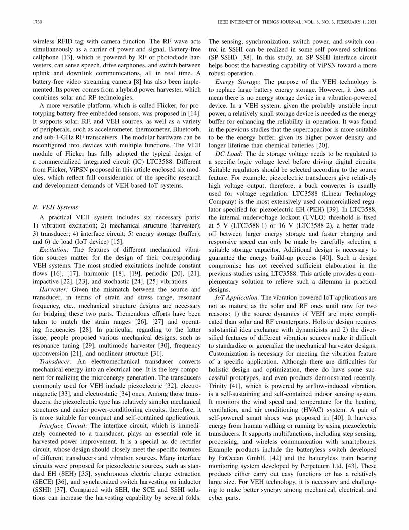
The sensing, synchronization, switch power, and switch con-trol in SSHI can be realized in some self-powered solutions(SP-SSHI) [38]. In this study, an SP-SSHI interface circuithelps boost the harvesting capability of ViPSN toward a morerobust operation.
Energy Storage: The purpose of the VEH technology isto replace large battery energy storage. However, it does notmean there is no energy storage device in a vibration-powereddevice. In a VEH system, given the probably unstable inputpower, a relatively small storage device is needed as the energybuffer for enhancing the reliability in operation. It was foundin the previous studies that the supercapacitor is more suitableto be the energy buffer, given its higher power density andlonger lifetime than chemical batteries [20].
DC Load: The dc storage voltage needs to be regulated toa specific logic voltage level before driving digital circuits.Suitable regulators should be selected according to the sourcefeature. For example, piezoelectric transducers give relativelyhigh voltage output; therefore, a buck converter is usuallyused for voltage regulation. LTC3588 (Linear TechnologyCompany) is the most extensively used commercialized regu-lator specified for piezoelectric EH (PEH) [39]. In LTC3588,the internal undervoltage lockout (UVLO) threshold is fixedat 5 V (LTC3588-1) or 16 V (LTC3588-2), a better trade-off between larger energy storage and faster charging andresponsive speed can only be made by carefully selecting asuitable storage capacitor. Additional design is necessary toguarantee the energy build-up process [40]. Such a designcompromise has not received sufficient elaboration in theprevious studies using LTC3588. This article provides a com-plementary solution to relieve such a dilemma in practicaldesigns.
IoT Application: The vibration-powered IoT applications arenot as mature as the solar and RF ones until now for tworeasons: 1) the source dynamics of VEH are more compli-cated than solar and RF counterparts. Holistic design requiressubstantial idea exchange with dynamicists and 2) the diver-sified features of different vibration sources make it difficultto standardize or generalize the mechanical harvester designs.Customization is necessary for meeting the vibration featureof a specific application. Although there are difficulties forholistic design and optimization, there do have some suc-cessful prototypes, and even products demonstrated recently.Trinity [41], which is powered by airflow-induced vibration,is a self-sustaining and self-contained indoor sensing system.It monitors the wind speed and temperature for the heating,ventilation, and air conditioning (HVAC) system. A pair ofself-powered smart shoes was proposed in [40]. It harvestsenergy from human walking or running by using piezoelectrictransducers. It supports multifunctions, including step sensing,processing, and wireless communication with smartphones.Example products include the batteryless switch developedby EnOcean GmbH. [42] and the batteryless train bearingmonitoring system developed by Perpetuum Ltd. [43]. Theseproducts either carry out easy functions or has a relativelylarge size. For VEH technology, it is necessary and challeng-ing to make better synergy among mechanical, electrical, andcyber parts.

LI et al.: ViPSN: VIBRATION-POWERED IoT PLATFORM 1731
(a) (b) (c) (d)
Fig. 2. ViPSN hardware architecture. (a) EGU. (b) ETU. (c) EEU. (d) EMU. (e) EUU.
III. VIPSN MODULES
The hardware architecture of ViPSN is shown in Fig. 2. Itencapsulates five units: 1) EGU; 2) ETU; 3) EEU; 4) EMU;and 5) EUU. Besides the hardware, an EDU with a customizedapp receives standard BLE signals sent from EUU for thedemo purpose.
A. EGU
For EGU, a commercial portable resonance speaker servesas the vibrator, like the demo design in [50]. It generates vibra-tions according to the records from real-world environments.It is self-contained with a battery pack inside and standardauxiliary port (AUX) for audio input. Different from a normalloudspeaker, it does not have a diaphragm. It produces soundsby vibrating the contacting hard medium. In other words, a res-onance speaker can convert the audio signal into a structuralvibration. Compared with the expensive and heavy profes-sional vibrator, this portable solution is a better option forthe developer working on vibration-powered IoT applications.
B. ETU
For ETU, the piezoelectric transducer is made of a circu-lar low-cost piezoelectric buzzer, whose rim is fixed at themoving part of the resonance speaker. The low-cost generatoris good for popularization. If this cheap and underperform-ing structure works well, there is no doubt for other moresophisticated designs. A mass is bonded at the center of theround-shape transducer, as shown in Fig. 2(a). When the base(moving part of the vibrator) undergoes vibration, the piezo-electric structure deflects. Such base excitation can be modeledwith the following dynamic equation:
− My(t) = Mx(t) + Dx(t) + Kx(t) (1)
where y is the displacement of the vibrating base, x is therelative beam deflection; and M, D, and K are the mass,damping coefficient, and stiffness of the piezoelectric struc-ture, respectively. The relation between input y and output xcan be expressed as follows in the frequency domain:
X(s)
Y(s)= − s2
s2 + 2ζωns + ω2n
(2)
where ωn = √K/M is a natural frequency and ζ = D/2/
√MK
is the damping ratio. From (2), the base-excited ETU actsas a high-pass unit-gain filter, whose cutoff frequency is ωn.Given a specific piezoelectric structure, the resonance and passband can be tuned by adjusting the weight of the proof mass;therefore, the base-excited structure is good at reproducing thevibration excitation above the designed ωn.
C. EEU
Under vibration excitation, the piezoelectric transducer pro-duces an alternating or fluctuating voltage. We can use asimple full-wave bridge rectifier for ac–dc power conversion,in order to power digital electronics. The full-wave bridge,i.e., SEH is regarded as the benchmark interface circuit forPEH. In this design, an SP-SSHI interface circuit is adopted.SP-SSHI increases the harvested power by realizing runningpower factor correction [44]. Like most renewable sources,such as solar and wind ones, maximum output power, but notconversion efficiency, is the most important design criteria ofthe interface circuit (first-stage power conditioning circuit).Compared with SEH, SP-SSHI can harvest a larger amount ofenergy under the same vibration excitation.
A piezoelectric structure can be modeled as an equivalentcurrent source ieq in parallel with its clamped capacitanceCp and dielectric leakage resistance Rp, as shown in Fig. 3.The equivalent current source is proportional to the relativevelocity, i.e.,
ieq(t) = αx(t) (3)
where ieq is the equivalent current source, and α is theforce–voltage factor of the piezoelectric structure. Because dis-placement x is alternating in vibration, ieq is also alternating.Thus, the voltage vp across the clamped capacitance Cp isalternating. SEH uses a bridge rectifier and filter capacitor toconvert the ac input into a smooth dc output. However, usingSEH cannot ensure that the energy is always flowing from themechanical part to the electrical part. In SEH, there is a phasedifference between the zero-crossing points of ieq and piezo-electric voltage vp, as shown by the dotted and dashed linesin Fig. 3(b). Therefore, energy returns from the electrical partto the mechanical part in some intervals [45].

1732 IEEE INTERNET OF THINGS JOURNAL, VOL. 8, NO. 3, FEBRUARY 1, 2021
(a) (b)
Fig. 3. SP-SSHI interface circuit used in the EEU. (a) Circuit topology. (b) Operating waveforms under harmonic excitation.
(a) (b)
Fig. 4. Charging history. (a) Using SP-SSHI. (b) Using SEH. (Storage capac-itor Cr: 47 μF, vibration frequency: 120 Hz, and acceleration magnitudes:0.33, 0.43, and 0.80 g.)
The SP-SSHI circuit [38] overcomes this problem by addinga synchronized switch branch in parallel with the piezoelec-tric output, as shown in Fig. 3(a). An inductive synchronizedswitch branch can make a rapid voltage inversion for vp whenieq crosses 0, as shown by the solid line in Fig. 3(b), so theextracted power becomes always positive. In other words, itmaintains unidirectional energy conversion from mechanicalto electrical domains. The envelope detectors and compara-tors are used for detecting the extreme instants of vp, whichare equivalent to the zero-crossing instants of ieq, and car-rying out switching actions. The positive envelope detectorsare composed of R1, D1, and C1. The transistors T1 acts asa comparator comparing the base voltage (vp) and the emittervoltage (vp envelop). Once vp attains a maximum value andbegins to drop, T1 conducts. The current from T1 collectorturns on the corresponding transistor switch T3. An inductiveswitching path is formed by D5, T3, and inductor Li. It realizesa rapid positive to negative voltage inversion for vp. The com-plementary part of the circuit is used for negative-to-positivevoltage inversion at minimum vp. A more detailed principleof SP-SSHI can be referred to [38] and [44].
The charging history of the storage capacitor (Vstore) withdifferent interface circuits, i.e., SEH and SP-SSHI, is shownin Fig. 4. The charging tests are carried out with 120-Hzharmonic excitations at different vibration levels (accelerationmagnitudes ranges from 0.33, 0.43, to 0.80 g). The minimumstartup voltage of the buck converter for generating a con-stant output voltage is Vstore = 5 V. As we can observe from
Fig. 4, under small excitation, i.e., 0.33 g acceleration, nei-ther SP-SSHI nor SEH can reach this 5-V threshold. Whenacceleration magnitude rises to a critical value 0.43 g, SP-SSHI can make the task, but SEH cannot. Both SEH andSP-SSHI can properly work under 0.80 g excitation. Yet, whenfully charged, under this excitation level, SP-SSHI can offer(13.5/8.2)2 = 2.71 folds of energy, compared with SEH.
D. EMU
In a VEH system, EMU plays an essential role to guaranteea robust and reliable operation under complicated vibrationconditions. It is responsible not only for providing tempo-rary capacitive energy storage for the extra harvested energyfrom ETU but also for supplying power at a constant volt-age to EUU. On the other hand, many vibration sources areintermittent, variable, and unpredictable, so vibration-powereddevices should operate in various vibration environments,such as intermittent mode or transient mode. EMU has tomaximize the harvested energy income from the supply side,minimize the energy dissipation in energy conversion, andproperly deliver power on the user’s demand. The softwareprogram should be carried out with an awareness of the storedenergy level. However, most off-the-shelf commercial regula-tors IC only emphasized stable logic voltage output. Necessaryinteractions between energy storage and EUU were not suf-ficiently supported. For example, LTC3588, as mentioned inSection II-B, integrates a low-loss full-wave bridge rectifierand a high-efficiency buck converter for PEH power condi-tioning. Its power good output pin (PGOOD) is actually usedfor indicating the availability of stable output voltage, ratherthan the stored energy level [39].
In this article, an enhanced EMU is developed by makinga complementary design to LTC3588. It produces necessaryenergy-level indicating signals to the energy user for bet-ter operation under fluctuating or intermittent vibrations. Asshown in Fig. 2(c), the EMU has three parts: 1) a dc–dc buckconverter; 2) an energy storage capacitor; and 3) a comparatorwith adjustable hysteresis. An external comparator is responsi-ble for detecting the energy level of the storage capacitor. Twoadditional energy-level indicating signals Pgood and Psleep areadded beyond the two internal fixed-level UVLO signals (Pstartand Pclose) in LTC3588.

LI et al.: ViPSN: VIBRATION-POWERED IoT PLATFORM 1733
(a)
(b)
(c)
(d)
(e)(f)
Fig. 5. Workflow of ViPSN under harmonic excitation. (a) Voltage history of Vstore and Vcc. (b) Load current. (c) Harmonic excitation (magnitude: 1.67g, frequency: 150 Hz, and duration: 48 s). (d) Working phases. (e) Enlarged view during periodical sensing and transmitting. (f) Enlarged view duringinitialization.
During the operation, the EMU provides two internalenergy-level indicating signals to itself and three external sig-nals to the EUU, such that ViPSN can properly handle differenttasks. Pstart sets when Vstore > 5 V and Pclose sets whenVstore < 3.4 V. Pstart starts the dc–dc power conversion ofLTC3588. Pclose turns off the converter. There might be sev-eral rounds of lockouts and restarts before the output voltagereaches a stable level, because of the depletion and refill ofthe storage capacitor. Besides the fixed UVLO thresholds, thePGOOD pin of LTC3588 offers further information on theoutput voltage stability. The PGOOD pin is logic high whenthe output voltage of LTC3588 is above 92% of the desiredregulation voltage (3.3 V in this study). If Vcc falls below thisthreshold, it turns to logic low. It should be noted that PGOODis not a storage-level indicating signal. Pgood added in thisstudy provides a real storage-level indicating signal. It comeswith the rising edge of the comparator’s output. It denotesthat the storage capacitor of EMU has gained sufficient energyto ensure the execution of the most power-consuming atomicoperation. Psleep comes with the falling edge of the compara-tor’s output. It warns that the energy storage of EMU is inshortage; therefore, the EUU must take an emergent process tosave the critical data and then go to the ultralow-power deep-sleep mode. In addition, via adjusting the resistor network ofthe comparator, we can change the voltage thresholds for gen-erating Pgood and Psleep so as to ensure proper operations underdifferent excitation conditions.
E. EUU
A BLE node as the EUU is used to carry out temperaturesensing and transmitting functions. Fig. 5(a) and (b) shows thestorage voltage profile and the current consumption in a wholeoperation cycle under harmonic excitation. First, the capacitorneeds to be charged above VPstart the UVLO rising threshold,
such that the dc–dc regulator starts. Once Vcc attains the min-imum workable digital level, it performs the most necessaryinitialization, then immediately goes to sleep and waits forstable supply voltage, which is indicated by PGOOD. Undera stable supply voltage, further initialization can be carriedout. The energy build-up phase starts as well. During theenergy build-up phase, EUU stays in the deep-sleep mode andwaits for the Pgood interruption indicating there is sufficientstored energy, such that to avoid wasting the harvested energy.This phase ends until the storage voltage reaches the VPgoodthreshold. After the EMU setting Pgood, EUU starts to exe-cute some functions. In the periodical sensing and transmittingphase, ViPSN periodically senses the temperate and trans-mits the signal to the remote receiver. To keep ViPSN in thepower-on state for a longer time, EMU also sends out a Psleepinterrupt signal at the falling edge of the comparator output.With this low-energy indicating signal, EUU could stop exe-cuting energy-consuming functions and enter the deep-sleepphase. The energy build-up process restarts. ViPSN remainsin hibernation until the next round of intensive vibration.
IV. EMU DESIGN CONSIDERATIONS
As an IoT platform designed for developers, who want tobuild VEH battery-free devices, ViPSN provides a solutionto better coordinate the energy income and IoT demands.It should be adaptive to a wide range of vibration excita-tions, including the intermittent and fluctuating ones. It shouldalso be reconfigurable to support a wide range of peripher-als regarding their operation features and power requirements.EMU plays an essential role in fulfilling these tasks.
A. Energy Build-Up Phase
Fig. 6 shows the voltage traces of ViPSN in operationwith or without energy indicating signals. Fig. 7 further

1734 IEEE INTERNET OF THINGS JOURNAL, VOL. 8, NO. 3, FEBRUARY 1, 2021
(a)
(b)
(c)
Fig. 6. Operation phases with or without additional energy indicat-ing signals under the same harmonic excitation (magnitude: 0.97 g andfrequency: 150 Hz). (a) Unsuccessful startup using a small storage capacitor(Cr = 10 μF) without the additional energy indicating signal. (b) Successfulbut slow startup using a large storage capacitor (100 μF) without additionalenergy indicating signal. (c) Successful startup using a small storage capacitor(10 μF) with additional energy indicating signals.
illustrates the energy quotas in the conventional fixed stor-age thresholds scheme offered by LTC3588 and the newViPSN EMU solution with two more tunable thresholds. Underthe same harmonic excitation, ViPSN with energy indicatingsignals can perform sensing and transmitting operations suc-cessfully even using a small capacitor as the energy buffer.When there is no energy indicating signal, ViPSN cannotprovide a stable voltage Vcc. Because the available energy,which is determined by the fixed VPstart and VPclose threshold,i.e., (1/2)Cr(V2
Pstart − V2Pclose), might be sufficient to ener-
gize neither initialization nor normal operation. Under sucha condition, the system cannot successfully startup, given thecontinuous power supply outage, as shown in Fig. 6(a) andthe corresponding red segment in Fig. 7(a).2 It is possible torealize successful startup by adopting larger storage capacitor(Cr increases from 10 to 100 μF), as shown in Fig. 6(b) andthe corresponding green segment in Fig. 7(a). This requires alonger cold-start time. On the other hand, by adding an addi-tional Pgood indicating signal, we insert an energy build-upphase right after the necessary initialization. Such a new phaseensures that the stored energy is sufficient to meet the require-ments of normal operations, including temperature sensing,wireless communication, etc. The successful startup processwith the help of energy indicating signals is shown in Fig. 6(c)and the corresponding green segment of the lower curve inFig. 7(b). The energy quota increases after inserting VPgoodand VPsleep can be observed by comparing Fig. 7(a) and (b).
ViPSN can better operate under different vibration condi-tions by tuning the VPgood level. Especially, in transient mode
2The absolute energy quota provided by the storage in Fig. 6(a) case is67 μJ, which is more than the required energy for initialization as listed inTable I. However, considering that conversion efficiency is not perfectly 100%,67-μJ stored energy is still insufficient to initialize ViPSN.
(a) (b)
(c) (d)
Fig. 7. Storage energy versus threshold voltages under different storagecapacitance. (a) and (c) Conventional scheme without energy indicating signal.(b) and (d) ViPSN EMU with two energy indicating signals. VPstart and VPcloseare fixed thresholds, while VPgood and VPsleep are tunable according to themost energy-consuming atomic operation.
TABLE IVIPSN POWER AND ENERGY STATISTICS
vibration, the energy that can be harvested is limited, we canlower the threshold (VPgood) for generating Pgood, so that EUUcan be activated more rapidly after initialization and then com-plete the easy transient sensing and transmission tasks. Incontinuous vibration, we can increase the threshold for gen-erating Pgood accordingly, so as to provide sufficient energyto EUU for performing more comprehensive tasks. It is alsopossible to shorten the active period by increasing the thresh-old (VPsleep) for generating Psleep. Given that ViPSN is drivenby an intermittent vibration, starting from a higher level ofresidual energy can shorten the next energy build-up interval.
Via the energy-warning interrupt signal Psleep offered byEMU, EUU can keep track of the energy storage conditionpassively and economically. The passive solution consumesless power than the energy-expensive active polling, whichsamples the storage voltage all the time. More importantly,in this EMU solution, the VPgood and VPsleep thresholds canbe tuned by adjusting the resistor ladder according to theenergy demands of all atomic operations of EUU, as shown inFig. 7(c) and (d). ViPSN is ready to be extended to embracemore types of peripherals. EUU does not need to be repro-grammed for energy monitoring. It enables developers tocreate new applications more easily.
B. Energy Consumption and Storage Capacitor Selection
The amount of energy stored in EMU should be esti-mated according to the harvested power, on-demand dynamic

LI et al.: ViPSN: VIBRATION-POWERED IoT PLATFORM 1735
energy consumption, and static power. The equation govern-ing the time-dependent energy level in the stored capacitor isformulated as follows:
η
[∫ t
t0Ph(τ )dτ − Estore(t)
]=
∫ t
t0Pstatic(τ )dτ +
t0<t<τ∑i
Etask,i
(4)
where Ph is the harvested power, which is obtained after theEEU. η is the average dc–dc energy conversion efficiency.The EUU carries out various tasks, including initialization,sensing, transmitting, and sleeping. The energy consumptionEtask,i of these tasks are listed in Table I. Pstatic representsthe static power consumption of the system. It includes theoperating power of comparator Pcomp, buck converter Pdc-dc,and leakage power Pleak, which is caused by the parallelleakage resistor of the storage capacitor. Considering thesenonnegligible energy consumption, Pstatic is summarized asfollows:
Pstatic(t) = Pcomp(t) + Pdc-dc(t) + Pleak(t). (5)
Owing to the UVLO capability, the buck converter willnot turn on until the storage voltage (Vstore) reaches theUVLO threshold (VPstart), as shown in Fig. 6. During thecold-start phase, there is only Pleak leakage power consump-tion. However, the buck converter has a much higher powerconsumption during the operation. That explains the suddenstorage voltage drops in the initialization phase, as shown inFigs. 4 and 5(a). In addition, once the converter is switchedon, the system starts to perform initialization, in which thecomparator and EUU are enabled at the same time. As shownin Fig. 5(b), the load current reaches a peak value during theinitialization phase. Therefore, in this study, initialization isthe most energy-consuming task. More generally speaking, thestorage capacitor needs to satisfy the following equations, sothat the system has enough energy to exit the cold-start phase,and complete the most energy-consuming task:
Cstore ≥ max{Ci} (6)
Ci =2[∫
TiPstatic(t)dt + Etask,i
η V2task,i − V2
Pclose
. (7)
In (6), Cstore indicates the value of the storage capacitance, andCi and Vtask,i represent the minimum capacitance and voltagethreshold for successfully carrying out the ith task. In thisdesign, the minimum kick-off voltage Vtask,i for initializationis VPstart (5 V). Other Vtask,i must be larger than VPclose (3.4 V)to avoid sudden power outage.
V. IMPLEMENTATION
A. Hardware
A prototyped ViPSN is implemented, as shown in Fig. 1.The specifications are listed in Table II. An LTC3588-1 ICis used for a regulation purpose. Its dc–dc power conversionefficiency is around 80%–90% under different input volt-age, output voltage, and loading current [39]. MIC841 [46],a micropower, precision-voltage comparator with adjustable
TABLE IIVIPSN SPECIFICATIONS
Fig. 8. Package transaction for ESB. ViPSN is used as the transmitter. In thisexample, the packet is delivered successfully at the second retransmission.
Fig. 9. Acceleration records at three spots of the Clifton Suspension Bridgein U.K.
hysteresis is used to provide energy indicating signals. Aprogrammable BLE System on Chip (SoC) nRF52832 byNordic Inc. [47] serves as the EUU. The EUU has three parts:1) transceiver; 2) sensor; and 3) CPU. The sensor part uses theon-chip temperature sensor in nRF52832. Two remote edgedevices are designed for receiving the signals sent out byViPSN. One is a cell phone, which runs a customized mobileapp, as shown in Fig. 1(c). Another is a host PC, which installsa USB BLE receiver module and data processing program.
B. Overhead and Minimum Storage Capacitor
The statistics of power and energy of different tasks areshown in Table I. Before performing regular sensing and trans-mission tasks, for both EMU and EUU, the initialization phaseis necessary. So the harvested energy must first satisfy theinitialization consumption. The listed initialization energy con-sumption (56.8 μJ) is the sum of the initial configurationpower of the buck converter, comparator, and EUU. The staticaverage power consumption of EMU (8.0 μW) includes that of

1736 IEEE INTERNET OF THINGS JOURNAL, VOL. 8, NO. 3, FEBRUARY 1, 2021
(b) (c) (d)
(a)
Fig. 10. Workflow of ViPSN under intermittent mode excitation. (a) Vstore and Vcc under the bridge vibration excitation. (b) Acceleration at location #1.(c) Enlarged view during initialization. (d) Enlarged view during periodical sensing and transmitting.
the comparator, buck converter, and leakage power. The mini-mum storage capacitance can be derived as 8.46 μF accordingto (7). Since initialization is the most energy-consuming taskin this study, this is the minimum capacitance for ensuringsuccessful initialization.
C. Dependability Communication
In this study, we use Enhanced ShockBurst (ESB) [48] fordependability wireless transmission. ESB is a basic protocolthat supports two-way data packet communication, includ-ing packet buffering, packet acknowledgment, and automaticretransmission of lost packets. It supports a star network topol-ogy with one receiver and up to eight transmitters. For ViPSN,energy and its relationship to wireless communication is acritical subject. Fig. 8 shows a typical wireless communica-tion process with several important parameter configurationsthat can be optimized to accommodate the vibration-poweredsystem. For enhancing the transmission reliability, the trans-mitter has opportunities to retransmit the packet until theACK is finally received. In this case, considering the trade-off between the reliability and power consumption power, weset the delay as 600 μs and the retransmission number as 3.
VI. EVALUATION AND CASE STUDY
A. Setting
Via configuring the thresholds of VPgood and VPsleep, ViPSNcan perform new use cases and applications under differ-ent excitation conditions, including intermittent and transientvibrations. We evaluate the performance of ViPSN basedon the power lifetime and Quality of Service (QoS). Thepower lifetime means the time when EUU remains power on.The QoS is the number of successful packets transmitted byViPSN.
B. Harmonic Vibrations
Fig. 5 shows the operation under harmonic vibration, whoseduration is 48 s, frequency is 150 Hz, and peak acceleration is1.67 g. In the experiment, we use a 47-μF capacitor as the stor-age component in EMU. Fig. 5(e) shows the enlarged view ofthe current waveform in one round of temperature sensing and
(a) (b)
Fig. 11. Performance of ViPSN under simulated bridge vibrations. (a) QoS.(b) Power lifetime.
transmission. The system wakes up from the low-power mode,and immediately carries out temperature sampling, preprocess-ing, and crystal upgrading, finally, processes and transmits thedata. Fig. 5(f) shows the current waveform in the initializationphase.
C. Intermittent Vibrations
In this case, we use the resonant speaker to simulate the real-world vibration of a suspended bridge. The vibration data set isprovided by the EH Network Data Repository.3 It is an onlinerepository that provides a common resource for sharing dataon energy availability. The data used in the case are recordedfrom different locations at some suspension segments of theClifton Suspension Bridge in the U.K. When cars pass bya suspended segment of the bridge, significant vibrations areinduced at some locations.
Fig. 9 shows the vibration records at three positions.Location #1 is at the end of the suspended bridge segment,which is close to the pillars. Location #2 and location #3 areon the protective metal railing, which separates the sidewalk.In our study, we use a GY-61 DXL335 3-axis accelerometermodule [49] for providing feedback, such that to make surethe reproduction of the bridge vibration is credible.
We configure ViPSN to periodically sense the local temper-ature and transmit the result to the host device. In order to
3http://eh-network.org/data/

LI et al.: ViPSN: VIBRATION-POWERED IoT PLATFORM 1737
(a)
(b)
(c)
(d)
Fig. 12. Workflow of ViPSN under transient mode excitation. (a) Vstore and Vcc of ViPSN with SP-SSHI. (b) Enlarged view of the transient transmittingand excitation. (c) Burst vibration acceleration. (d) Enlarged view of the excitation.
fulfill such periodic tasks, we select a 47-μF storage capaci-tor. We set the voltage thresholds VPgood and VPsleep as 6.6 and5.5 V, which guarantee that the system can perform at leastfive rounds of temperature sensing and transmissions.
As shown in Fig. 10(a) and (b), we record the traces ofVstore, Vcc, and acceleration at location #1. The peak accelera-tion of this vibration excitation is around 2 g, and the durationis 60 s. At the instant of Pstart interrupt, the voltage suddenlydrops from 5.0 to 4.7 V. Owing to the 47-μF storage capac-itor, the BLE sensor is able to remain power-on after thissudden voltage drop, so that it can proceed into the followingphases. The enlarged view of the initialization instant is shownin Fig. 10(c). Fig. 10(d) shows that during periodical sensingand transmitting every second in normal operation.
Fig. 11(a) and (b) shows the performance of ViPSN withSP-SSHI or SEH interface circuits, in terms of QoS and powerlifetime, respectively. Under the same vibration excitation,ViPSN using SP-SSHI can sense and transmit 30% more datapackets compared with that using SEH. At location #2, theQoS of ViPSN is less. Because the vibration at location #2is weaker and sparser, the harvested energy can hardly reachthe threshold for enabling sensing and transmitting functions.Therefore, the corresponding QoS is smaller. On the otherhand, even under such a weak vibration, ViPSN using SP-SSHIcan guarantee at least five rounds of sensing and transmissions,while that using SEH makes nothing.
The newly proposed EMU defines two more thresholds,which respectively generate Pgood and Psleep control sig-nals. We give a preference to response Psleep before Pgood.Therefore, once the initialization is finished, ViPSN can sleepand maintain in the power-on state for a long time, regardlessof using SP-SSHI or SEH, as shown in Fig. 11(b). As we canobserve, the power lifetime of ViPSN using SP-SSHI is longerthan that using SEH.
D. Transient Excitation
In this case, we use a transient signal to excite the speaker.ViPSN is reconfigured to catch this burst-mode vibrationenergy. As shown in Fig. 12(c), the transient excitation onlylasts for 780 ms. Its peak acceleration is around 2 g. In
(a) (b)
Fig. 13. Performance of ViPSN under pulse excitation. (a) QoS. (b) Powerlifetime.
response to such a transient mode vibration excitation, wechoose a 10-μF storage capacitor, whose capacitance is abovethe lower limit of the successful operation. In order to shortenthe duration of the cold-start and energy build-up phases, wetune the voltage threshold VPgood to 5.0 V, which is the sameas VPstart.
For this case, we set ViPSN to do one transmission as soonas Pgood is triggered, which is different from the periodic tasks.As shown in Fig. 12, through the power conditioning processof the SP-SSHI interface circuit and the optimized EMU andEUU, ViPSN can carry out six rounds of transmitting functionsand later maintain the power-on state for up to 10 s. However,as reliable transmission requires an accurate and stable high-frequency clock, we can observe some transmission failuresduring the unstable Vcc period (1.38–1.53 s) in the cold-startphase.
We also compare the performance of ViPSN when using SP-SSHI or SEH. Fig. 13 shows that under the transient excitation,ViPSN can achieve better QoS and longer power lifetime whenusing SP-SSHI. The QoS with SP-SSHI is about 1.5 times ofthat with SEH.
VII. CONCLUSION
This article introduced ViPSN, a new opensource IoT plat-form built for VEH, battery-free sensing, and computing.Based on the specific design considering various vibrationconditions, ViPSN can harvest considerable energy underharmonic, intermittent, or transient mechanical vibrations for
1738 IEEE INTERNET OF THINGS JOURNAL, VOL. 8, NO. 3, FEBRUARY 1, 2021
supporting different types of IoT functions. By using ViPSN,developers with different academic backgrounds can quicklyprototype their vibration-powered or motion-powered devicestoward new applications in different scenarios. We imple-mented ViPSN in the modular forms in order to supportrapid reconfiguration and future extensibility. We evaluatedthe usability and performances of ViPSN in three study cases.The results showed that the prototyped ViPSN device canrobustly operate under different forms of vibration excitations.We look forward that ViPSN can make a valuable contributionto the prosperity of both research communities of VEH andbattery-free IoT systems.
REFERENCES
[1] J. Hester and J. Sorber, “The future of sensing is batteryless, intermittent,and awesome,” in Proc. 15th ACM Conf. Embedded Netw. Sens. Syst.(Sensys’17), 2017, p. 21.
[2] P. Rawat, K. D. Singh, H. Chaouchi, and J. M. Bonnin, “Wireless sensornetworks: A survey on recent developments and potential synergies,” J.Supercomput., vol. 68, no. 1, pp. 1–48, 2014.
[3] X. Li, X. Ma, P. Zhang, P. Tian, and J. Wei, “Escape or exploit?:A noise-modulation-based communication under harsh interference,” inProc. 7th Int. Workshop Real World Embedded Wireless Syst. Netw.,2018, pp. 31–36.
[4] M. Gorlatova, J. Sarik, G. Grebla, M. Cong, I. Kymissis, andG. Zussman, “Movers and shakers: Kinetic energy harvesting for theInternet of Things,” in Proc. ACM Int. Conf. Meas. Model. Comput.Syst., 2014, pp. 407–419.
[5] T. Starner, “Human-powered wearable computing,” IBM Syst. J., vol. 35,nos. 3–4, pp. 618–629, 1996.
[6] D. Ma, G. Lan, M. Hassan, W. Hu, and S. K. Das, “Sensing, comput-ing, and communications for energy harvesting IoTs: A survey,” IEEECommun. Surveys Tuts., vol. 22, no. 2, pp. 1222–1250, 2nd Quart., 2019.
[7] S. Naderiparizi, Z. Kapetanovic, and J. R. Smith, “WISPCam: An RF-powered smart camera for machine vision applications,” in Proc. 4thInt. Workshop Energy Harvesting Energy Neutral Sens. Syst., 2016,pp. 19–22.
[8] A. Saffari, M. Hessar, S. Naderiparizi, and J. R. Smith, “Battery-freewireless video streaming camera system,” in Proc. IEEE Int. Conf. RFID(RFID), Phoenix, AZ, USA, 2019, pp. 1–8.
[9] J. Hester and J. Sorber, “Batteries not included,” XRDS Crossroads ACMMag. Students, vol. 26, no. 1, pp. 23–27, 2019.
[10] N. Jackson, J. Adkins, and P. Dutta, “Capacity over capacitance forreliable energy harvesting sensors,” in Proc. 18th Int. Conf. Inf. Process.Sens. Netw., Montreal, QC, Canada, 2019, pp. 193–204.
[11] A. Gomez, L. Sigrist, T. Schalch, L. Benini, and L. Thiele, “Efficient,long-term logging of rich data sensors using transient sensor nodes,”ACM Trans. Embedded Comput. Syst., vol. 17, no. 1, p. 4, 2018.
[12] A. P. Sample, D. J. Yeager, P. S. Powledge, A. V. Mamishev, andJ. R. Smith, “Design of an RFID-based battery-free programmablesensing platform,” IEEE Trans. Instrum. Meas., vol. 57, no. 11,pp. 2608–2615, Nov. 2008.
[13] V. Talla, B. Kellogg, S. Gollakota, and J. R. Smith, “Battery-free cell-phone,” Proc. ACM Interact. Mobile Wearable Ubiquitous Technol.,vol. 1, no. 2, pp. 1–20, 2017.
[14] J. Hester and J. Sorber, “Flicker: Rapid prototyping for the batterylessInternet-of-Things,” in Proc. 15th ACM Conf. Embedded Netw. Sens.Syst. (Sensys), 2017, p. 19.
[15] J. Liang and W.-H. Liao, “Impedance network for power optimisationin piezoelectric energy harvesting systems,” HKIE Trans., vol. 18, no. 4,pp. 32–38, Jan. 2011.
[16] L. Zhao, L. Tang, J. Liang, and Y. Yang, “Synergy of windenergy harvesting and synchronized switch harvesting interface cir-cuit,” IEEE/ASME Trans. Mechatronics, vol. 22, no. 2, pp. 1093–1103,Apr. 2017.
[17] T. Tan and Z. Yan, “Analytical solution and optimal design for galloping-based piezoelectric energy harvesters,” Appl. Phys. Lett., vol. 109,no. 25, 2016, Art. no. 253902.
[18] J. Liang and W. Liao, “Impedance modeling and analysis for piezo-electric energy harvesting systems,” IEEE/ASME Trans. Mechatronics,vol. 17, no. 6, pp. 1145–1157, Dec. 2012.
[19] M. Safaei, H. A. Sodano, and S. R. Anton, “A review of energy harvest-ing using piezoelectric materials: State-of-the-art a decade later (2008–2018),” Smart Mater. Struct., vol. 28, no. 11, 2019, Art no. 113001.
[20] M. Guan and W.-H. Liao, “Design and analysis of a piezoelectricenergy harvester for rotational motion system,” Energy Convers. Manag.,vol. 111, pp. 239–244, Mar. 2016.
[21] S. Fang, X. Fu, X. Du, and W.-H. Liao, “A music-box-like extended rota-tional plucking energy harvester with multiple piezoelectric cantilevers,”Appl. Phys. Lett., vol. 114, no. 23, Jun. 2019, Art. no. 233902.
[22] L. Gu and C. Livermore, “Impact-driven, frequency up-converting cou-pled vibration energy harvesting device for low frequency operation,”Smart Mater. Struct., vol. 20, no. 4, Mar. 2011, Art. no. 045004.
[23] X. Fu and W.-H. Liao, “Nondimensional model and parametric studiesof impact piezoelectric energy harvesting with dissipation,” J. SoundVib., vol. 429, pp. 78–95, Sep. 2018.
[24] J. T. Scruggs, “On the causal power generation limit for a vibratoryenergy harvester in broadband stochastic response,” J. Intell. Mater. Syst.Struct., vol. 21, no. 13, pp. 1249–1262, Feb. 2010.
[25] Y. Jia, “Review of nonlinear vibration energy harvesting: Duffing, bista-bility, parametric, stochastic and others,” J. Intell. Mater. Syst. Struct.,vol. 31, no. 7, pp. 921–944, Apr. 2020.
[26] M. Evans, L. Tang, K. Tao, and K. Aw, “Design and optimisation of anunderfloor energy harvesting system,” Sens. Actuat. A, Phys., vol. 285,pp. 613–622, Jan. 2019.
[27] H. Liu, R. Hua, Y. Lu, Y. Wang, E. Salman, and J. Liang, “Boosting theefficiency of a footstep piezoelectric-stack energy harvester using thesynchronized switch technology,” J. Intell. Mater. Syst. Struct., vol. 30,no. 6, pp. 813–822, Apr. 2019.
[28] L. Tang, Y. Yang, and C. K. Soh, “Toward broadband vibration-basedenergy harvesting,” J. Intell. Mater. Syst. Struct., vol. 21, no. 18,pp. 1867–1897, Dec. 2010.
[29] E. S. Leland and P. K. Wright, “Resonance tuning of piezoelectric vibra-tion energy scavenging generators using compressive axial preload,”Smart Mater. Struct., vol. 15, no. 5, p. 1413, 2006.
[30] S. Shahruz, “Design of mechanical band-pass filters for energy scaveng-ing,” J. Sound Vib., vol. 292, nos. 3–5, pp. 987–998, 2006.
[31] M. F. Daqaq, R. Masana, A. Erturk, and D. Dane Quinn, “On the roleof nonlinearities in vibratory energy harvesting: A critical review anddiscussion,” Appl. Mech. Rev., vol. 66, no. 4, p. 23, 2014.
[32] S. Roundy, P. K. Wright, and J. Rabaey, “A study of low level vibrationsas a power source for wireless sensor nodes,” Comput. Commun., vol. 26,no. 11, pp. 1131–1144, 2003.
[33] S. P. Beeby et al., “A micro electromagnetic generator for vibrationenergy harvesting,” J. Micromech. Microeng., vol. 17, no. 7, p. 1257,2007.
[34] E. O. Torres and G. A. Rincón-Mora, “Electrostatic energy-harvestingand battery-charging CMOS system prototype,” IEEE Trans. CircuitsSyst. I, Reg. Papers, vol. 56, no. 9, pp. 1938–1948, Sep. 2008.
[35] E. Lefeuvre, A. Badel, C. Richard, L. Petit, and D. Guyomar, “Acomparison between several vibration-powered piezoelectric genera-tors for standalone systems,” Sens. Actuat. A, Phys., vol. 126, no. 2,pp. 405–416, 2006.
[36] E. Lefeuvre, A. Badel, C. Richard, and D. Guyomar, “Piezoelectricenergy harvesting device optimization by synchronous electric chargeextraction,” J. Intell. Mater. Syst. Struct., vol. 16, no. 10, pp. 865–876,2005.
[37] D. Guyomar, A. Badel, E. Lefeuvre, and C. Richard, “Toward energyharvesting using active materials and conversion improvement by non-linear processing,” IEEE Trans. Ultrason., Ferroelect., Freq. Control,vol. 52, no. 4, pp. 584–595, Apr. 2005.
[38] J. Liang and W.-H. Liao, “Improved design and analysis of self-poweredsynchronized switch interface circuit for piezoelectric energy harvestingsystems,” IEEE Trans. Ind. Electron., vol. 59, no. 4, pp. 1950–1960,Apr. 2012.
[39] LTC3588-1 Data Sheet, Linear Technologie, Milpitas, CA, USA, 2010.[40] Q. Huang, Y. Mei, W. Wang, and Q. Zhang, “Toward battery-free wear-
able devices: The synergy between two feet,” ACM Trans. Cyber Phys.Syst., vol. 2, no. 3, pp. 1–18, 2018.
[41] T. Xiang et al., “Powering indoor sensing with airflows: A trinity ofenergy harvesting, synchronous duty-cycling, and sensing,” in Proc. 11thACM Conf. Embedded Netw. Sens. Syst. (Sensys’13), 2013, p. 16.
[42] Technology of EnOcean GmbH. Accessed: 2020. [Online]. Available:https://www.enocean.com/en/products/
[43] Technology of Perpetuum Ltd. Accessed: 2020. [Online]. Available:https://perpetuum.com/technology/

LI et al.: ViPSN: VIBRATION-POWERED IoT PLATFORM 1739
[44] K. Zhao, Y. Zhao, and J. Liang, “A vibration-powered bluetooth wirelesssensor node with running PFC power conditioning,” in Proc. IEEE Int.Symp. Circuits Syst. (ISCAS), Baltimore, MD, USA, 2017, pp. 1–4.
[45] J. Liang and W. Liao, “Piezoelectric energy harvesting and dissipationon structural damping,” J. Intell. Mater. Syst. Struct., vol. 20, no. 5,pp. 515–527, 2009.
[46] MIC841/2 Data Sheet, Microchip Technol., Chandler, AZ, USA, 2017.[47] nRF52832 Data Sheet, Nordic Semicond., Trondheim, Norway, 2016.[48] (2019). Enhanced ShockBurst (ESB). [Online]. Available: https://
developer.nordicsemi.com/nRF_Connect_SDK/doc/0.4.0/nrf/ug_esb.html/
[49] ADXL335 Data Sheet, Analog Devices, Norwood, MA, USA, 2010.[50] C.-L. Kuo, S.-C. Lin, and W.-J. Wu, “Fabrication and performance eval-
uation of a metal-based bimorph piezoelectric MEMS generator forvibration energy harvesting,” Smart Mater. Struct., vol. 25, no. 10, 2016,Art no. 105016.
Xin Li (Graduate Student Member, IEEE) receivedthe B.E. and B.Ec. degrees from the NorthUniversity of China, Taiyuan, China, in 2016. Heis currently pursuing the Ph.D. degree with theSchool of Information Science and Technology,ShanghaiTech University, Shanghai, China.
He is also with the Shanghai Institute ofMicrosystem and Information Technology, ChineseAcademy of Sciences, Beijing, China, and withthe University of Chinese Academy of Sciences,Beijing. His research interests include vibration
energy harvesting, ubiquitous computing, and Internet of Things.Dr. Li was a recipient of the First Place of the International Conference
on Embedded Wireless Systems and Networks Dependability Competition in2019 and the First Runner Up of the IEEE Industrial Electronics SocietyInter-Chapter Paper Competition in 2019.
Li Teng (Graduate Student Member, IEEE) receivedthe B.S. degree in microelectronics from HefeiUniversity of Technology, Hefei, China, in 2015.He is currently pursuing the Ph.D. degree with theSchool of Information Science and Technology,ShanghaiTech University, Shanghai, China.
He worked as a Power Management IntegratedCircuit Design Engineer with Wuxi ETEKMicroelectronics Company Ltd., Wuxi, China. Hisresearch interests include low-power analog andmixed-signal integrated circuit, energy harvesting,
and high-efficiency power management.
Hong Tang (Student Member, IEEE) received theB.E. degree in telecommunication engineering fromFuzhou University, Fuzhou, China, in 2017. Heis currently pursuing the master’s degree with theSchool of Information Science and Technology,ShanghaiTech University, Shanghai, China.
His research interests includes vibration-poweredIoT system and mobile computing, especially theirpower solution, cyber-electromechanical synergy,and applications of IoT systems.
Jingying Chen received the B.E. degree in automa-tion from Jilin Engineering Normal University,Changchun, China, in 2011.
He has worked with Shanghai Shipyard ShippingCompany Ltd., Shanghai, China, and involved inmany hands-on engineering projects, such as geolog-ical exploration equipment. Since 2018, he has beenwith the Mechatronics and Energy TransformationLaboratory, School of Information Science andTechnology, ShanghaiTech University, Shanghai, asa Research Engineer.
Haoyu Wang (Senior Member, IEEE) receivedthe bachelor’s degree (with Distinguished Hons.)in electrical engineering from Zhejiang University,Hangzhou, China, in 2009, and the Ph.D. degreein electrical engineering from the University ofMaryland at College Park, College Park, MD, USA,in 2014.
In 2014, he joined the School of InformationScience and Technology, ShanghaiTech University,Shanghai, China, where he is currently a tenuredAssociate Professor. His research interests include
power electronics, plug-in electric and hybrid electric vehicles, the appli-cations of wide-bandgap semiconductors, renewable energy harvesting, andpower management integrated circuits.
Dr. Wang is an Associate Editor of the IEEE TRANSACTIONS
ON INDUSTRIAL ELECTRONICS, the IEEE TRANSACTIONS ON
TRANSPORTATION ELECTRIFICATION, and the CPSS Transactions onPower Electronics and Applications.
Yu Liu (Member, IEEE) received the B.S. andM.S. degrees in electrical power engineering fromShanghai Jiao Tong University, Shanghai, China, in2011 and 2013, respectively, and the Ph.D. degreein electrical and computer engineering from theGeorgia Institute of Technology, Atlanta, GA, USA,in 2017.
He is currently a Tenure-Track Assistant Professorwith the School of Information Science andTechnology, ShanghaiTech University, Shanghai. Hisresearch interests include modeling, protection, fault
location, state/parameter estimation of power systems, and power electronicsystems.
Minfan Fu (Senior Member, IEEE) received theB.S., M.S., and Ph.D. degrees in electrical and com-puter engineering from the UM-SJTU Joint Institute,Shanghai Jiao Tong University, Shanghai, China, in2010, 2013, and 2016, respectively.
From 2016 to 2018, he was a PostdoctoralFellow with the Center for Power ElectronicsSystems, Virginia Polytechnic Institute and StateUniversity, Blacksburg, VA, USA. He is currently anAssistant Professor with the School of InformationScience and Technology, ShanghaiTech University,
Shanghai. His research interests include megahertz wireless power transfer,high-frequency power conversion, high-frequency magnetic design, and appli-cation of wide-bandgap devices.
Dr. Fu won the IES-SYPA Competition for a conference paper at IECON2019. He is currently an Associate Editor for IEEE IES Industrial ElectronicsTechnology News.
Junrui Liang (Member, IEEE) received the B.E.and M.E. degrees in instrumentation engineeringfrom Shanghai Jiao Tong University, Shanghai,China, in 2004 and 2007, respectively, and thePh.D. degree in mechanical and automation engi-neering from the Chinese University Hong Kong,Hong Kong, in 2010.
He is currently an Assistant Professor with theSchool of Information Science and Technology,ShanghaiTech University, Shanghai. His researchinterests include energy conversion and power con-
ditioning circuits, kinetic energy harvesting and vibration suppression, IoTdevices, and mechatronics.
Dr. Liang is a recipient of two Best Paper Awards in the IEEE InternationalConference on Information and Automation in 2009 and 2010, respectively.He is an Associate Editor of IET Circuits, Devices and Systems and theGeneral Chair of the second International Conference on Vibration and EnergyHarvesting Applications in 2019.