transformer experiements
TRANSCRIPT

8/15/2019 Transformer Experiements
http://slidepdf.com/reader/full/transformer-experiements 1/40

8/15/2019 Transformer Experiements
http://slidepdf.com/reader/full/transformer-experiements 2/40
Experiment No.:1
Aim: TO PERFORM OPEN CIRCUIT & SHORT CIRCUIT TEST ON A SINGLE-PHASE
TRANSFORMER.
Apparatus: 1) 230/115V, 1KVA Single Phase transformer (1No.)
2) 0-250V, Single Phase dimmerstat (1No.)
FOR O.C. TEST FOR S.C. TEST3) Voltmeter (0-300 V) (0-150 V) AC. each 1 No. 6) Voltmeter (0-75 V.) AC. 1No.
4) Ammeter (0-1 A) AC, 1 No. 7) Ammeter (0-5 A), (0-10 A) Ac. 1 each.
5) Wattmeter (300V, 1A) 1No. 8) Wattmeter (75 V, 5 A) 1No.
Circuit Diagram:FOR O.C. TEST.
V
A
V
0-150 V0-300 V
0-1 A
M
C
L
V
1- PH230 V
SUPPLY
1 PHASE
DIMMERSTAT
WATTMETER
300 V,1A
230/115 V, 1 PHASE
TRANSFORMER
FOR S.C. TEST.
V
A
A
0-10 A0-75 V
0-5 A
M
C
L
V
1- PH
230 VSUPPLY
1 PHASEDIMMERSTAT
WATTMETER75 V, 5 A
230/115 V,1 PHASE
TRANSFORMER
Theory: It should cover the following
1) Purpose of O.C. & S.C. test.
1) Brief explanation about connection diagram.
2) Simplified equivalent circuit of a transformer and its parameters.

8/15/2019 Transformer Experiements
http://slidepdf.com/reader/full/transformer-experiements 3/40
3) Formulae for efficiency and regulation.
4) Formulae for voltage drop for different power factor loads.
Procedure: FOR O.C. TEST
1) Connect the circuit as shown.
2) Ensure that the dimmerstat Position is at zero.
3) Switch on the single phase AC. Supply.
4) Apply rated voltage of 230V, to the primary side of transformer.5) Note the ammeter, voltmeter and wattmeter readings.
FOR S.C. TEST
1) Connect the circuit as shown.2) Ensure that the dimmerstat position is at ‘0’ (zero).
3) Switch on the single phase AC. Supply.
4) Slowly increase the output voltage of the dimmerstat till the
ammeter on primary side shows rated current of 4.35 amp.
5) Note the ammeter, voltmeter & wattmeter readings.
Precautions:
1) All the connections should be perfectly tight.2) Supply should not be switched ON until& unless the connections are checked by the teacher.
3) Do not bend while taking the readings
4) No loose wires should lie on the work table.
5) Thick wires should be used for current circuit and flexible wires for voltage circuits.
6) The multiplying factor of wattmeter should be correctly used.
Observations:
FOR O.C.TEST (Read on primary side.)
Rated input Voltage
V0
No load current
I0
No load power
W0
230V
FOR S.C. TEST (Read on primary side)
Short circuit voltage
Vsc
Rated primary current
(i.e full load value)
Isc
Short circuit power
Wsc
4.35amp
Calculations:
FOR O.C. TEST
No load power factor =coso = Wo / (Vo Io)
Magnetising component of Io = Iµ = Io sino amps.
Core loss component of Io = Ic = Io coso amps.
Core loss resistance Ro = Vo/ Ic ohm.Magnetising reactance Xo = Vo/ Iµ ohms.
Core loss in transformer at any load = Wo
8/15/2019 Transformer Experiements
http://slidepdf.com/reader/full/transformer-experiements 4/40
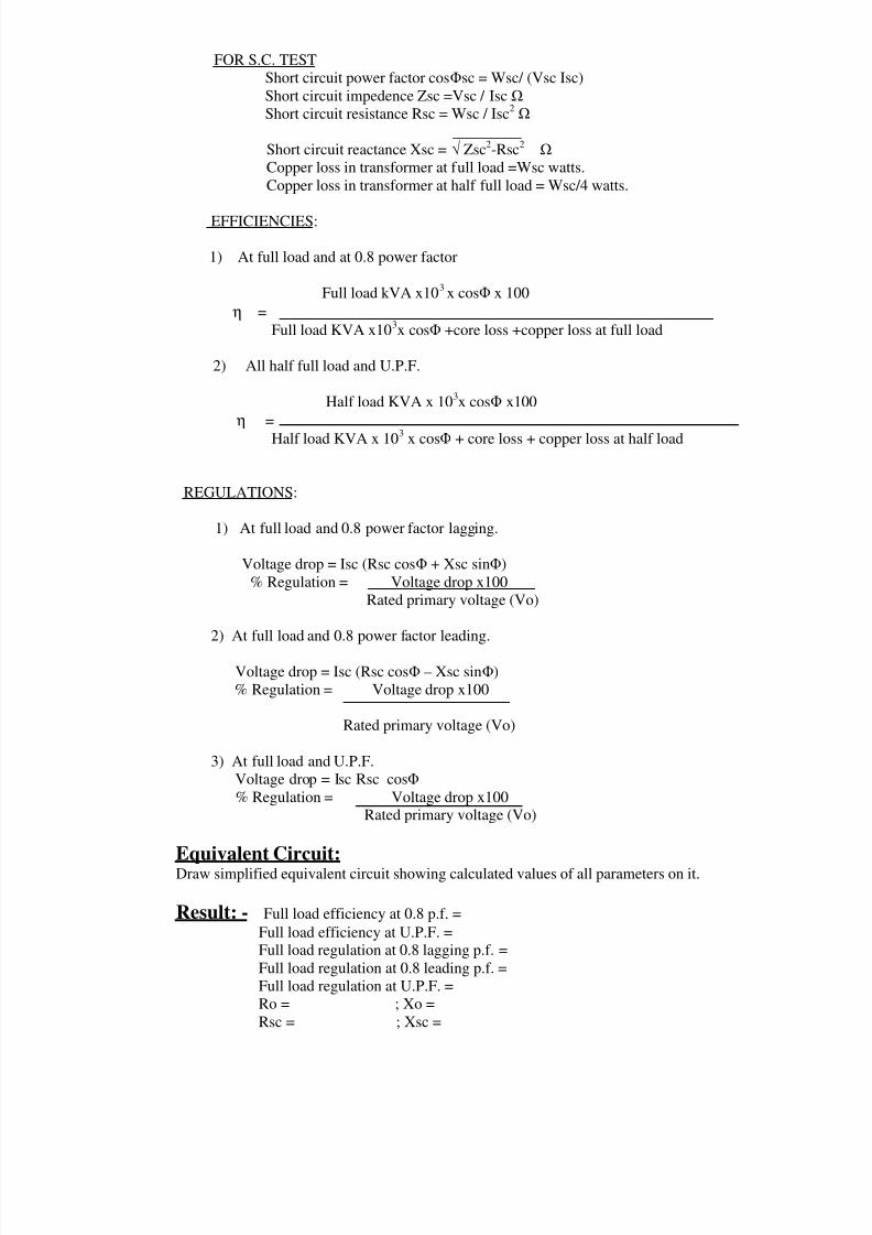
FOR S.C. TEST
Short circuit power factor cossc = Wsc/ (Vsc Isc)
Short circuit impedence Zsc =Vsc / Isc
Short circuit resistance Rsc = Wsc / Isc2
_________
Short circuit reactance Xsc = Zsc2-Rsc2
Copper loss in transformer at full load =Wsc watts.
Copper loss in transformer at half full load = Wsc/4 watts.
EFFICIENCIES:
1) At full load and at 0.8 power factor
Full load kVA x103x cos x 100
η =
Full load KVA x103x cos +core loss +copper loss at full load
2) All half full load and U.P.F.
Half load KVA x 103x cos x100
η =
Half load KVA x 103 x cos + core loss + copper loss at half load
REGULATIONS:
1) At full load and 0.8 power factor lagging.
Voltage drop = Isc (Rsc cos + Xsc sin)
% Regulation = Voltage drop x100
Rated primary voltage (Vo)
2) At full load and 0.8 power factor leading.
Voltage drop = Isc (Rsc cos – Xsc sin)
% Regulation = Voltage drop x100
Rated primary voltage (Vo)
3) At full load and U.P.F.
Voltage drop = Isc Rsc cos
% Regulation = Voltage drop x100Rated primary voltage (Vo)
Equivalent Circuit:Draw simplified equivalent circuit showing calculated values of all parameters on it.
Result: - Full load efficiency at 0.8 p.f. =
Full load efficiency at U.P.F. =Full load regulation at 0.8 lagging p.f. =
Full load regulation at 0.8 leading p.f. =
Full load regulation at U.P.F. =
Ro = ; Xo =
Rsc = ; Xsc =

8/15/2019 Transformer Experiements
http://slidepdf.com/reader/full/transformer-experiements 5/40
Viva Questions: -Q.1. What is the significance of O.C. & S.C. test?
Q.2. Why h.v. winding is kept open during O.C. test and 1.v. winding is shorted
during S.C. test in case of large transformers?
Q.3. In O.C. test, a voltmeter is connected across secondary winding and still it is
called as O.C. test. Why?
Q.4. What will happen if dc supply instead of ac supply is applied to a transformer?
Q.5. Which is the alternate method for finding efficiency and regulation of a
transformer other than O.C. & S.C. tests ? What are their advantages over eachother?
Q.6. What is the importance of equivalent circuit?
Q.7. Why regulation of transformer is negative for leading p.f. load?
Q.8. “ The wattmeter reading during O.C. test is considered as core loss whilewattmeter reading during S.C. test is considered as copper loss” Justify.

8/15/2019 Transformer Experiements
http://slidepdf.com/reader/full/transformer-experiements 6/40
Experiment No.:2
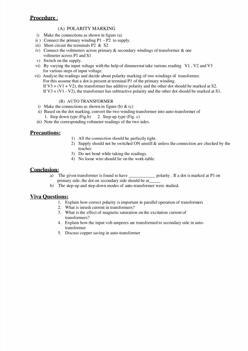
Aim : TO PERFORM (a) POLARITY MARKING ON TWO WINDING TRANSFORMER.
(b) CONVERSION OF TWO-WINDING TRANSFORMER
INTO AUTO TRANSFORMER.
Apparatus : 1) Two winding transformer ( 230 / 115 V, 1 KVA )
2) Voltmeter (0-300 V) 1 No. ( 0-150 V ) 2Nos.
3) Ammeter (0-5 A ) 3 Nos.4) Loading rheostat ( 5 KW )
5) Single phase dimmerstat ( 2 KVA )
6) Transformer ( Teaser with tapping on primary & secondary )
Circuit Diagram :
V
VV0-300 V
0-150 V
0-150 V
230/115 V, 1 KVATransformer
1 Phase Dimmerstat
P1
P2
S1
S2
230 V 1-phase
A.C. supply
V1V2
V3
Figure (a) Polarity marking on two winding transformer.
V0-300 V
0-600 V
230/115 V, 1 KVATransformer1 Phase Dimmerstat
P1
P2
230 V
1-phase
A.C. supply
V1
V2
v
V0-300 V
0-600 V
230/115 V, 1 KVATransformer1 Phase Dimmerstat
P1
P2
230 V 1-phaseA.C. supply
V1
V2
v
Fig (b) & (c) Conversion of two-winding transformer into auto-transformer
Theory : It should cover the following points 1) Explanation of dot and cross marking in general
2) Concept of polarity marking of two mutually coupled coils.
3) Importance of correct polarity in parallel operation of transformers
4 ) Auto transformer
8/15/2019 Transformer Experiements
http://slidepdf.com/reader/full/transformer-experiements 7/40

8/15/2019 Transformer Experiements
http://slidepdf.com/reader/full/transformer-experiements 8/40

8/15/2019 Transformer Experiements
http://slidepdf.com/reader/full/transformer-experiements 9/40
6) Then increase the load in steps till rated current of the transformer & note down
corresponding readings. Take atleast 8 readings.
7) Calculate efficiency & regulation for each reading.
Observation Table:
No-load secondary voltage E2 = ---------- Volts
Sr.No. I1Amp V1 Volts W1 Watts I 2 Amp V2 Volts W2 Watts % Reg % 1
2
3
4
5
Calculations:
O/ Power W2
% η = -------------------- x 100
I/P power W1
No load voltage (E2) – voltage at load (V2)
% Reg = ---------------------------------------------------------- x 100
No load voltage (E2)
Graph: Plot the graph output Power Vs efficiency.
Precautions:1) All the connection should be perfectly tight.
2) Supply should not be switched ON unstill & unless the connection are checked by the
teacher.
3) Do not bend while taking the readings.
4) No loose wire should lie on the work-table.
5) Thick wire should be used for current circuit and flexible wires for voltage circuits.
6) The multiplying factor of wattmeter should be correctly noted.
Result: The % efficiency & regulation of transformer at full load condition is found as follows.
Percentage efficiency = ------------------%
Percentage regulation = ------------------%
Conclusion: Transformer efficiency initially increases as the load on transformer is increased.
After maximum efficiency if we increase the load further, the efficiency of transformer reduces.Also terminal voltage reduces as the load is increased.
Viva Questions:1. What is the condition for max efficiency?2. What is the condition for zero voltage regulation?
3. Which is the other method of finding efficiency and regulation?
4. Draw phasor diagram of transformer at full load and 0.5 p.f. lagging.
5. Draw phasor diagram of transformer at full load and 0.5 p.f. leading.
6. What is the normal nature of output power Vs efficiency curve & why?

8/15/2019 Transformer Experiements
http://slidepdf.com/reader/full/transformer-experiements 10/40
Experiment No.:4
Aim: TO PERFORM BACK TO BACK TEST ON SINGLE PHASE TRANSFORMERS.
Apparatus: 1) Two transformers, (1- phase, 1 kVA, 220 /115 V,)
2) Two dimmer stats, (0-270 V, 1- phase, 5 A)
3) Voltmeter, (0-300 V),( 0-75 V)
4) Ammeter, (0-2 A),( 0-10 A)
5) Wattmeter (0-300 V, 2 A),( 0-75 V, 10 A)
6) Connecting wires.
Circuit Diagram:
1PhaseAC
Supply
1PhaseAC
Supply
A
V
v
A
230 V
115 V
230 V
115 V
1 KVA Xmer
S 3
0-2 A
0-300 V
0-75 V0-10 A
C
M
V
L
C
M L
V
300 V,2 A Wattmeter
75 V, 10 A Wattmeter
S 2
S 1
1PhaseDimmerstat
1PhaseDimmerstat
V1
V2
I1
I2
W1
W2
Theory: It should include the following.1. Purpose of this test
2. How full load losses are produced in this test without actually loading any
transformer.
3. Explanation about the circuit diagram.
Procedure: 1) Make the connections as shown in circuit diagram.
2) Keep switches S2 & S3 open and the dimmerstats at zero position.
3) Switch ON the supply and check the correctness of polarities of the two transformers.
If V2 = 0 then polarities of connected transformers are correct i.e. connections are back to
back and emf induced in secondaries are in phase opposition but if V2 = 2xKxV1, then
secondary emfs are in phase,in that case change the polarities of any one secondary winding.
4) Note down the readings of V1, I1 and W1
5) Now close switch S2, S3 and increase dimmerstat output voltage gradually so that full
load current flows through secondary windings.
6) Note down V2 , I2 and W2. While doing so , the values shown by V1, I1 and W1 should not
deviate from their earlier readings.

8/15/2019 Transformer Experiements
http://slidepdf.com/reader/full/transformer-experiements 11/40

8/15/2019 Transformer Experiements
http://slidepdf.com/reader/full/transformer-experiements 12/40
Experiment No.:5
Aim: TO STUDY SCOTT. CONNECTIONS OF TRANSFORMER.
(Study of three phase to two phase conversion)
Apparatus: Ammeters (0-5 A, AC) 3 Nos ; (0-10 A, AC) 2 Nos.
Voltmeters (0-600 V; AC) 1 Nos, (0-150 V; Ac) 2 Nos.
Transformer 1-phase, 1 kVA, with 86.6% tap on 415V side
Transformer 1-phase, 1 kVA, with 50% tap on 415V side
Dimmer stat (0-440 V, 3 phase) 1 Nos.
Connecting wires, etc.
Circuit Diagram:
0-5 A
S 2
S 1
A
A
A
v
A
0-10 A
0-5 A
0-150 V
0-150 Vv
Primary of mainXmer
Secondary ofmain Xmer
LOAD
LOAD
0-10 A
3 PhaseSupply440 V
v 0-600 V
V 2T
I1T
I 2T
I 1M
V 2M
I 2M
V
TEASER Xmer
Theory: It should cover the following.
1. Explanation and mathematical proof of how a balanced two-phase supply can be obtained by using Scott
connection.
2. Phasor diagram illustrating the phase quadrature between the secondary voltages of the two transformers.
Procedure: 1. Connect the circuit as shown.
2. Use 86.6% tapping for teaser transformer and 50% tapping for main transformer.
3. Keep both loads zero
4. Switch on the 3-ph. supply and take the readings.
5. Vary the loads as per given in observation table and take the readings.

8/15/2019 Transformer Experiements
http://slidepdf.com/reader/full/transformer-experiements 13/40

8/15/2019 Transformer Experiements
http://slidepdf.com/reader/full/transformer-experiements 14/40

8/15/2019 Transformer Experiements
http://slidepdf.com/reader/full/transformer-experiements 15/40
5) Note the meter readings and the speed with the load at zero.
6) Increase the load in steps keeping the D.C. generator voltage constant at 170 V.
Note the D.C. generator voltage, generator current, motor current, motor voltage,
Power and speed.
7) Take more readings increasing the load gradually till the full load is reached.
8) Calculate performance parameters & plot the different graphs.
Observation Table: Armature resistance of generator Ra= ………Ω
Sr.No.
MOTOR SIDESpeed GENERATOR
SIDE
Vm Im WmVolt Amp Watt
N
rpmV dc I dc
Volts Amp
1234
5
Calculations: (For each reading):
Power factor of motor = Wm / (√√√√3 Vm. Im)
O/P of generator = Vdc x Idc.
Total losses of generator = I2
dc Ra + constant losses.
Constant loss = ½ x wattmeter reading at no load condition.
O/P Power of motor = I/P to generator. = O/P of generator + total losses of generator
MOTOR EFFICIENCY
O/P Power of motor
% η = ---------------------------- x 100
I/P Power of motor
No -N
Slip (s) = ---------- x 100
No
No = No load speed
N = Speed at load
Graph: Draw graphs (on same graph paper) of motor output power versus
i) motor efficiency
ii) motor input currentiii) motor power factor
iv) motor speed
Result: The speed falls, the power factor (Lagging) improves and the current increases, with an increase in the
output. The efficiency increases and is maximum near full load.

8/15/2019 Transformer Experiements
http://slidepdf.com/reader/full/transformer-experiements 16/40
8/15/2019 Transformer Experiements
http://slidepdf.com/reader/full/transformer-experiements 17/40
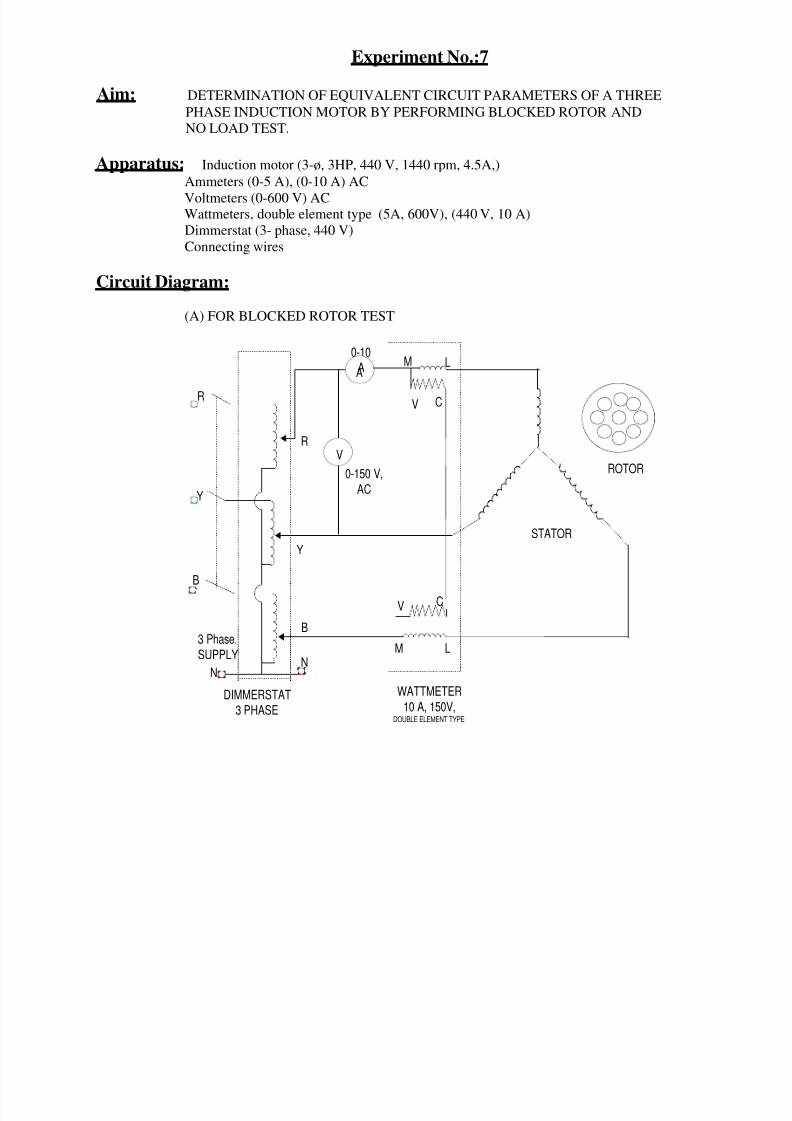
Experiment No.:7
Aim: DETERMINATION OF EQUIVALENT CIRCUIT PARAMETERS OF A THREE
PHASE INDUCTION MOTOR BY PERFORMING BLOCKED ROTOR AND
NO LOAD TEST.
Apparatus: Induction motor (3-ø, 3HP, 440 V, 1440 rpm, 4.5A,)
Ammeters (0-5 A), (0-10 A) AC
Voltmeters (0-600 V) ACWattmeters, double element type (5A, 600V), (440 V, 10 A)
Dimmerstat (3- phase, 440 V)
Connecting wires
Circuit Diagram:
(A) FOR BLOCKED ROTOR TEST
0-10
AA
V
M
V
L
C
ROTOR
M L
CV
R
Y
B
0-150 V,
AC
3 Phase.
SUPPLY
STATOR
WATTMETER
10 A, 150V,DOUBLE ELEMENT TYPE
DIMMERSTAT
3 PHASE
N
R
Y
B
N

8/15/2019 Transformer Experiements
http://slidepdf.com/reader/full/transformer-experiements 18/40

8/15/2019 Transformer Experiements
http://slidepdf.com/reader/full/transformer-experiements 19/40

8/15/2019 Transformer Experiements
http://slidepdf.com/reader/full/transformer-experiements 20/40
Plot net power input versus square of input voltage Vo2 , the intercept of the curve with power axis
will give Pf and Pc.
Shunt resistance Ro = Vo2(rated) / Pc
No-load power-factor Cos o = Pc/ ( Vo(rated).Io( at rated Vo) )
Shunt reactance Xo = Vo(rated). / Io( at rated Vo).Sin o
Equivalent Circuit:Draw equivalent circuits of 3-phase I. M. at no-load and blocked rotor conditions.
Result: Draw complete equivalent circuit of 3-phase I. M. indicating the calculated values of all parameters on it.
Viva Questions:1. What are the various losses in an Induction motor?
2. What is the analogy between O.C. & S.C. test of transformer & no load test & Block rotor test of
an Induction motor?
3. For an IM, Pf = 40W/ph , net stator input = 70W/ph, calculate iron loss.
4. What is skin effect?
5. What is the effect of temperature rise on winding resistance?

8/15/2019 Transformer Experiements
http://slidepdf.com/reader/full/transformer-experiements 21/40

8/15/2019 Transformer Experiements
http://slidepdf.com/reader/full/transformer-experiements 22/40

8/15/2019 Transformer Experiements
http://slidepdf.com/reader/full/transformer-experiements 23/40

8/15/2019 Transformer Experiements
http://slidepdf.com/reader/full/transformer-experiements 24/40
Observation Table: Radius of brake drum r = 0.15 m.
Calculations:
Output torque T = [(F1-F2) x 9.81 x r ] N.m where is radius of brake drum.
Output power Po = 2NT/60 watts.
Input power Pi = Vm.Im
Po
%η = ---------- x 100
Pi
Graph: Plot speed Vs torque and output power Vs efficiency.
Conclusion: At light load the motor speed is high and it reduces fast with rise in load.
Viva Questions:
1) What is the significance of back e.m.f. in a d.c. motor?
2) What is the chief advantage of a d.c. series motor?
3) What is the necessity of starter in a d.c. motor?
4) Why is a d.c. series motor used to start heavy loads?
5) Can a d.c. series motor operate on an a.c. supply?
6) Armature core of a dc machine is always laminated, why?7) Why the D.C. series motor is not operated at zero or light loads?
Sr.
No.
Vm
(Volts)
Im
(Amps)
F1
(kg)
F2
(Kkg)
N
(rpm)

8/15/2019 Transformer Experiements
http://slidepdf.com/reader/full/transformer-experiements 25/40

8/15/2019 Transformer Experiements
http://slidepdf.com/reader/full/transformer-experiements 26/40
Precautions: 1) All connections should be perfectly tight and no loose wire should lie on
the work table.
2) Before switching ON the dc supply , ensure that the starter’s moving arm
is at it’s maximum resistance position.
3) Do not switch on the supply, until and unless the connection are checked
by the teacher
4) Avoid error due to parallax while reading the meters.
5) Hold the tachometer with both hands steady and in line with the motor shaftso that it reads correctly.
Observations:
Motorside
Generator side
Sr.No.
V m I m Vg I g
SpeedN
rpm.
Calculations ( for all readings):
Generator output power Pg = Vg.IgGenerator constant loss Pc = motor constant loss = [Vm(no-load).Im(no-load)]/2
Generator input power = Pg + Ig2.Ra + Pc
Motor output power Pm(o) = Generator input power
Motor input power Pm(i) = Vm.Im
Motor efficiency is
Pm(o)
∴ % η = ----------------- x 100
Pm(i)
Graph: Plot on same graph paper
(i) Motor o/p power versus efficiency.
(ii) Motor o/p power versus Motor I/p current.
(iii) Motor o/p power versus speed.
Conclusion: With rise in load the motor current increases & the speed decreases slightly.
The efficiency initially increases with the load, reaches to its maximum & then decreases. The
curves obtained experimentally are shown on the graph
Viva Questions:1. How do you load the motor in this experiment?
2. What was the assumption made in calculations?
3. What is the condition for maximum torque of a D.C. shunt motor?
4. Why is the starter necessary ?
5. What is the power factor of the load used?

8/15/2019 Transformer Experiements
http://slidepdf.com/reader/full/transformer-experiements 27/40
Experiment No.:11
Aim: SPEED CONTROL OF D. C. SHUNT MOTOR. BY
1) Armature voltage control method (Below rated speed)
2) Field current control method (Above rated speed)
Apparatus: 1) D.C. Shunt motor – (230 V, 5 A, 1500 rpm, 1KW,)
2) D.C. starter.
3) D.C. Ammeter – (0-2 A)4) D.C. Voltmeter – (0-300 V)
5) Rheostat 400 Ω, 1.7 A, and 1000Ω 1.2 A
6) Tachometer
Circuit Diagram:
Theory: The theory should cover details about following points.
1) Principle of working of dc shunt motor
2) Relation between speed, armature resistance and flux.
3) Explanation of above circuit diagram.
4) Brief explanation about speed control by above two methods.
Procedure:1) Connect the circuit as shown above.
2) Adjust both rheostats at their minimum resistance position initially.
3) Switch ON the DC supply.
4) Turn the moving arm of starter to it’s minimum resistance position.
(A) FOR ARMATURE VOLTAGE CONTROL
5) Take a set of readings at minimum resistance position of both rheostats.
Keeping field current constant, vary the rheostat connected in armaturecircuit by increasing it’s value and note down the armature voltage and
corresponding values of speed.

8/15/2019 Transformer Experiements
http://slidepdf.com/reader/full/transformer-experiements 28/40

8/15/2019 Transformer Experiements
http://slidepdf.com/reader/full/transformer-experiements 29/40
Conclusion:It is observed that the speed of dc shunt motor increases above normal value by field
current control method and decreases below normal value by armature control method.
Discussion:-Q.1.What are the limitations of armature voltage control and field current control
methods?
Q.2. Why both rheostats are kept at minimum resistance position in the starting
condition?Q.3. What is starter? Why is it required?
Q.4. What is back emf? What is it’s significances?Q.5. Why is starter required during starting condition & not during running condition?
Q.6. Draw internal and external characteristics of dc shunt motor.
Q.7. What are the applications of dc shunt motor?
Q.8. Why are brushes made form carbon?
Q.9. Why is thin conductor used for field winding? & thick conductor for
armature winding?
8/15/2019 Transformer Experiements
http://slidepdf.com/reader/full/transformer-experiements 30/40
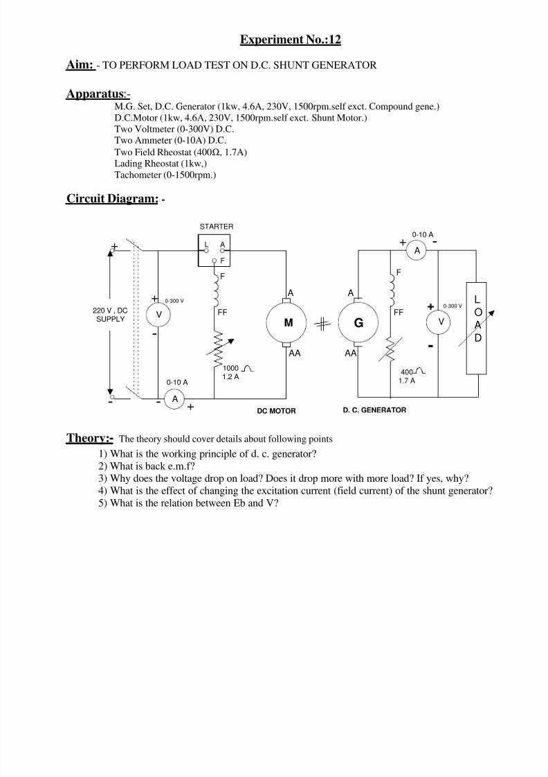
Experiment No.:12
Aim: - TO PERFORM LOAD TEST ON D.C. SHUNT GENERATOR
Apparatus:-M.G. Set, D.C. Generator (1kw, 4.6A, 230V, 1500rpm.self exct. Compound gene.)
D.C.Motor (1kw, 4.6A, 230V, 1500rpm.self exct. Shunt Motor.)
Two Voltmeter (0-300V) D.C.
Two Ammeter (0-10A) D.C.
Two Field Rheostat (400Ω, 1.7A)
Lading Rheostat (1kw,)
Tachometer (0-1500rpm.)
Circuit Diagram: -
+ -
F
4001.7 A
A
AA
D. C. GENERATOR
0-300 V
FF
G
LOAD
A
+
-
0-10 A
L A
F
STARTER
DC MOTOR
220 V , DCSUPPLY M
A
AA
F
FF
10001.2 A
0-300 V
A
VV
+
- -
-
+
+
0-10 A
Theory:- The theory should cover details about following points
1) What is the working principle of d. c. generator?
2) What is back e.m.f?3) Why does the voltage drop on load? Does it drop more with more load? If yes, why?
4) What is the effect of changing the excitation current (field current) of the shunt generator?
5) What is the relation between Eb and V?

8/15/2019 Transformer Experiements
http://slidepdf.com/reader/full/transformer-experiements 31/40
Observation Table:-
Speed = 1500 rpm (constant)
Procedure:-
1) Connection the ckt. As shown in figure.
2) Set the motor field rheostat to its minimum & generator field rheostat to maximum.3) Start the d.c. motor with the help of starter and adjust the speed to the rated speed of the
generator. Keep the speed constant throughout the experiment with help of motor field
rheostat.4) Adjust the field rheostat of the d.c. generator to obtain rated terminal voltage at no load
condition. Field rheostat adjusted at this position should nit be disturbed for this set.
5) Change the load current by varying load and note down the corresponding terminalvoltage. Take readings covering the range from no load to little over full load.
6) Plot terminal voltage Vs load current and efficiency Vs output.
Calculation:-O/p of generator
Generator efficiency ηG = -----------------------I/p of generator
O/p of motor
Motor efficiency ηm = --------------------I/p of motor
As O/P of motor = I/p of generator
O/p of generator
ηGηm = -------------------
I/p of motor
O/p of generator
ηG = --------------------I/p of motor
Graph:-
Sr.
No.
Motor Side
Vm Im
Volts Amp
Generator Side
Vg Ig
Volts Amp
Motor Input
= VmxIm(Watts)
Generator
Output =VgxIg (watts)
Efficiency of
generator =VgIg
------- x 100
VmIm
1/2

8/15/2019 Transformer Experiements
http://slidepdf.com/reader/full/transformer-experiements 32/40
Vg %Efficiency
ILOutput ofGenerator
Result & Conclusion:-The external characteristics of d.c. Shunt generator and efficiency curve are plotted. The
terminal voltage of a d.c. Shunt generator reduces as the load current is increased
Viva Questions:- 1) What should be done if the d.c. Shunt generator fails to build up?
2) What are the reasons of fall of terminal voltage of a d.c. shunt generator
3) Define armature reaction.4) What are the different types of losses in generator?
5) What is the e.m.f. Equation of generator?
6) What is the relation between Eb and V?7) What is the function of commutator?
8) What is the condition for maximum efficiency?

8/15/2019 Transformer Experiements
http://slidepdf.com/reader/full/transformer-experiements 33/40
Experiment No.:13
Aim: TO FIND REGULATION OF A THREE-PHASE ALTERNATOR BY OPEN CIRCUIT
AND SHORT CIRCUIT TESTS
Apparatus:1. Ammeter (0-5A) AC-1No; (0-1A) DC-1 No.
2. Voltmeter (0-300V) AC-1 No.3. Tachometer – 1 No.
4. Rheostats (400Ω. 1.7A) 1No; 1000Ω. 1.2A 1No.
5. Alternator 3 kVA, 4.2A, 1500 RPM, 3φ
6. D.C. Motor 3 HP, 220V, 1500RPM
7. Connecting wires etc.
Circuit Diagram: [A] OPEN CIRCUIT TEST
A
V
+
-
AFL
STARTER
F
10001.2A
A
AA
D. C. MOTOR
R
NB
Y
0-300 VAC
0-1ADC
-
+
+ -
1000
FIELD WDG OFALTERNATOR
,1.2A230 V DC
F
FF
FF
D C SUPPLY 230 V M A
ALTERNATOR

8/15/2019 Transformer Experiements
http://slidepdf.com/reader/full/transformer-experiements 34/40
[B] SHORT CIRCUIT TEST
ALTERNATOR
A
A
L F A+
-
FF
F
10001.2A
AA
A R
B
N
Y
D.C. MOTOR
FIELD WDGOF ALTERNATOR
+
-
(0-1A)DC
D.C. SUPPLY -+
F FF
(0 -5 A)AC
D.C. SUPPLY230 V
STARTER
M A
Theory: The theory should cover following points1. Meanings of regulation and synchronous impedance
2. Details about synchronous impedance method for finding regulation
3. Explanation about above circuit diagrams
4. List of other possible methods for finding regulation
Procedure:
[A] OPEN CIRCUIT TEST
1) Connect the circuit as shown.
2) Set potential divider to zero output position and motor field rheostat to minimum value.
3) Switch on dc supply and start the motor.
4) Adjust motor speed to synchronous value by motor field rheostat and note the meter readings.5) Increase the field excitation of alternator and note the corresponding readings.
6) Repeat step 5 till 10% above rated terminal voltage of alternator.
7) Maintain constant rotor speed for all readings.
[B] SHORT CIRCUIT TEST
1) Connect the circuit as shown.
2) Star the motor with its field rheostat at minimum resistance position and the potential divider set to zero
output.
8/15/2019 Transformer Experiements
http://slidepdf.com/reader/full/transformer-experiements 35/40
3) Adjust the motor speed to synchronous value.
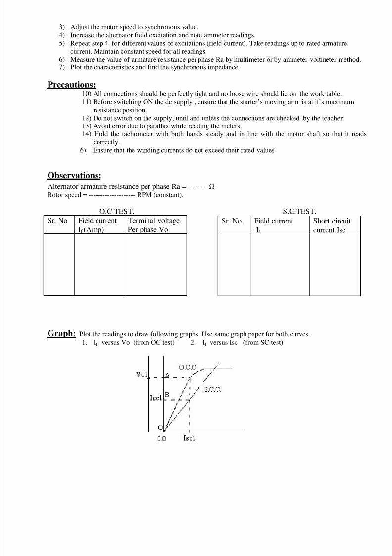
4) Increase the alternator field excitation and note ammeter readings.
5) Repeat step 4 for different values of excitations (field current). Take readings up to rated armature
current. Maintain constant speed for all readings
6) Measure the value of armature resistance per phase Ra by multimeter or by ammeter-voltmeter method.
7) Plot the characteristics and find the synchronous impedance.
Precautions:
10) All connections should be perfectly tight and no loose wire should lie on the work table.11) Before switching ON the dc supply , ensure that the starter’s moving arm is at it’s maximum
resistance position.
12) Do not switch on the supply, until and unless the connections are checked by the teacher
13) Avoid error due to parallax while reading the meters.14) Hold the tachometer with both hands steady and in line with the motor shaft so that it reads
correctly.
6) Ensure that the winding currents do not exceed their rated values.
Observations:
Alternator armature resistance per phase Ra = -------
Rotor speed = -------------------- RPM (constant).
O.C TEST. S.C.TEST.
Graph: Plot the readings to draw following graphs. Use same graph paper for both curves.
1. If versus Vo (from OC test) 2. If versus Isc (from SC test)
Sr. No. Field current
If
Short circuit
current Isc
Sr. No Field current
If (Amp)
Terminal voltage
Per phase Vo

8/15/2019 Transformer Experiements
http://slidepdf.com/reader/full/transformer-experiements 36/40
Calculations:OA Vo1
Synchronous impedance Zs = ---------- = ----------- for field current Isc1
OB Isc1
Isc1 is selected over the linear part of OCC, generally it corresponds to rated armature current.
Synchronous reactance Xs = (Zs
2
- Ra
2
)Where Ra = Armature resistance of alternator (per phase)
Calculate the excitation emf Eo and voltage regulation for full-load and
1. 0.8 lagging p.f.
2. UPF
3. 0.8 leading p.f.
Eo = √[(V cosφ + Ia Ra)2 + (V sin φ + Ia Xs)
2]
+ sign is for lagging pf load.
- sign is for leading pf load.
V = rated terminal voltage per phase of alternator
Eo - V
%Regulation = ------------ x 100
V
Phasor Diagrams:
Draw phasor diagrams for above three loads and verify the calculated results.
Result:Regulation of alternator at full load is found to be,
At unity pf = --------------
At 0.8 lagging = ---------------
At 0.8 leading = --------------
Synchronous Impedance varies for different values of excitation.
Viva Questions:1. Why OCC looks like B-H curve?
2. Why SCC is a straight line?
3. What is armature reaction effect?
4. What are the causes of voltage drop?5. When is the regulation negative and why?
6. Can we find regulation of a salient pole machine by this test? Justify your answer.
S.N. Zs Zs (av). Xs Xs (av).
8/15/2019 Transformer Experiements
http://slidepdf.com/reader/full/transformer-experiements 37/40
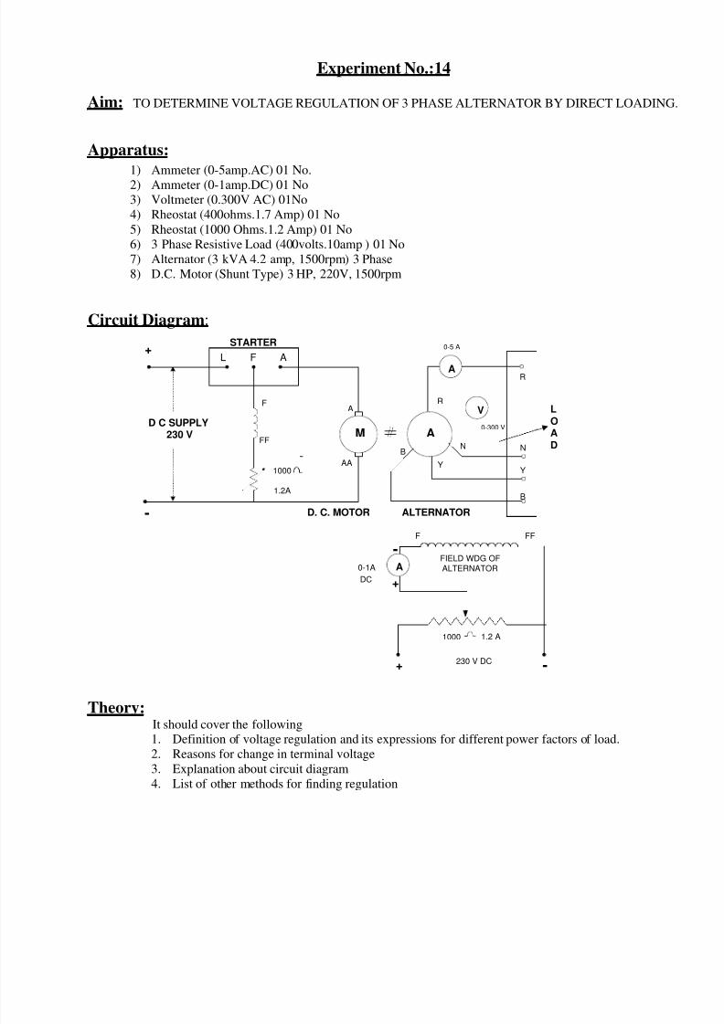
Experiment No.:14
Aim: TO DETERMINE VOLTAGE REGULATION OF 3 PHASE ALTERNATOR BY DIRECT LOADING.
Apparatus:
1) Ammeter (0-5amp.AC) 01 No.
2) Ammeter (0-1amp.DC) 01 No
3) Voltmeter (0.300V AC) 01No
4) Rheostat (400ohms.1.7 Amp) 01 No
5) Rheostat (1000 Ohms.1.2 Amp) 01 No
6) 3 Phase Resistive Load (400volts.10amp ) 01 No
7) Alternator (3 kVA 4.2 amp, 1500rpm) 3 Phase
8) D.C. Motor (Shunt Type) 3 HP, 220V, 1500rpm
Circuit Diagram:
A
+AFL
STARTER
F
1000
1.2A
A
AA
D. C. MOTOR
R
Y
BN
0-1A
DC
-
+
+ -
1000
FIELD WDG OF
ALTERNATOR
230 V DC
F
FF
FF
D C SUPPLY 230 V M A
ALTERNATOR
A
0-5 A
V
0-300 V
R
N
Y
B
1.2 A
L
OA
D
-
Theory:It should cover the following1. Definition of voltage regulation and its expressions for different power factors of load.
2. Reasons for change in terminal voltage
3. Explanation about circuit diagram
4. List of other methods for finding regulation

8/15/2019 Transformer Experiements
http://slidepdf.com/reader/full/transformer-experiements 38/40
Procedure:
1) Connect the circuit as shown in the diagram.
2) Keep load zero, set field potential divider to zero output voltage position.3) Keep field resistance of motor to its minimum value.
4) Start the motor with the help of starter.
5) With the field rheostat of motor adjust the speed to synchronous value.
6) Switch on DC supply of field (Alternator) and adjust the potential divider so that the voltmeter
reads rated voltage of the alternator. Note this voltage as no load voltage E.
7) Increase the load in steps till rated current of alternator and note the different sets of readings.8) Keep speed constant during all the readings with the help of motor field rheostat..
Precautions: 15) All connections should be perfectly tight and no loose wire should lie on the work table.
16) Before switching ON the dc supply , ensure that the starter’s moving arm is at it’s maximum
resistance position.
17) Do not switch on the supply, until and unless the connection are checked by the teacher
18) Avoid error due to parallax while reading the meters.19) Hold the tachometer with both hands steady and in line with the motor shaft so that it reads
correctly.
Observation: E = Terminal voltage at no load = volts.
Sr.
No.
Load current Terminal voltage
Vt
% Regulation
Calculations:E - Vt
% regulation = --------------- x 100
E
Result: The regulation at full load and ---- power factor is found to be ---------- %
Conclusion: As the load on the alternator increases the regulation also increases
Discussion:
1) Can the terminal voltage rise? Under which load?2) If the speed of the driving motor falls due to loading what will be the effects?
3) Give the classification of alternator on the basis of rotor and their application?
4) Why the excitation given to alternator is generally DC and not AC?
5) Mention disadvantages of determining the regulation of alternator by direct loading?
6) What is hunting in Alternator?7) What is the role of damper winding in Alternator?
8) What is chording and write their advantages?

8/15/2019 Transformer Experiements
http://slidepdf.com/reader/full/transformer-experiements 39/40
Experiment No.:15
Aim: TO PLOT V & INVERTED V CURVES OF A SYNCHRONOUS MOTOR.
Apparatus:
1) Synchronous motor 3 Phase, 3 HP, 440V, 8.2A ,1500 rpm,
2) DC shunt Generator 220V, 9A, 1500 rpm
3) Power factor meter-600V, 10A
4) Voltmeter AC- (0-600V), DC- (0-300V)5) Ammeter AC- (0-10A)
6) Ammeter DC (0-2A), DC (0-10A)
7) Rheostat-470 ohm, 1.2A,
8) Resistive load bank, tachometer, connecting wires, etc.
Circuit Diagram:
V
+ -
F
4001.7A
A
AA
D. C.
GENERATOR
R
B
Y0-300 VFF
3 PHASE
SUPPLY
440 V
GA
ALTERNATOR
V
L
O
A
D
M L
V C
V C
M L
A
+
-
0.2 A DC
-
+
+ -
FIELD WDG OF
ALTERNATOR
F FFPF- METER
600 V,10 A
0-10 A
A
0-10A
4
5
6
R
B
Y
A
230 V dc
Theory:
It should cover the following.
1. Significance of V & inverted V curves of synchronous motor.
2. Phasor diagram of a synchronous motor showing effect of change in excitation
3. Necessary condition for obtaining V & inverted V curves
4. Explanation about circuit diagram
Procedure:
1) Make the connections as shown in circuit diagram.2) Adjust the field rheostat of DC generator at maximum position, the potential divider at zero outpu
position and the load at off condition.
3) Switch on the 3-ph. supply, start the synchronous motor and let it run at its rated speed.
4) Switch on the DC supply and adjust the generator field current to a suitable value so that it generaterated voltage.
5) Increase the alternator field current and note down corresponding power factor and armature curren
covering a range from low lagging to low leading power factor through a unity power factor. Note
that armature current is minimum when the p.f. in unity.
6) Repeat step No.5 for some constant load on the Generator.

8/15/2019 Transformer Experiements
http://slidepdf.com/reader/full/transformer-experiements 40/40
Observations: [A] AT NO LOAD
[B] AT LOAD
Graph: Plot the curves between armature current (Ia) vs field current (If) and power factor(cosφ) vs field current (If)
Conclusion:
1. The variation of armature current (line current) and its power factor due to field current variation a
load and at no load are shown. The armature current is minimum when the PF is unity.
2. As load increases the V curve shifts upward and the inverted V curve shift towards right.
Viva Questions:
1. With what condition synchronous motor can be used as a synchronous condenser.
2. What are the special applications of an over excited synchronous motor.3. Explain the effect of change of excitation of a synchronous motor on its armature current.
4. Explain the effect of change of excitation of a synchronous motor on its power factor.
5. With the given excitation a synchronous motor draws a unity PF current . if the mechanicalload is increased what will be the power factor and current for the same excitation.
6. Why V curve shift upwards and inverted V curve shift right as the load increases.
7. Explain the effect of change of excitation of a synchronous generator on its armature current.
8. Explain the effect of change of excitation of a synchronous generator on its power factor.
Sr.No.
If Power Factor
(cosφ)
Ia
Sr.No.
If Power Factor
(cosφ)
Ia