training systems & models - romdidac · dwelling with built-in tutorial for component...
TRANSCRIPT

PAGES 152 - 156
PAGES 160 - 161
PAGES 172 - 175
PAGES 180 - 190
PAGES 194 - 196
PAGES 204 - 206
PAGES 157 - 159
PAGES 162 - 171
PAGES 176 - 179
PAGES 191 - 193
PAGES 197 - 203
PAGES 207 - 209
Training panels
Safety training
PLC
Regulation
Motor system
Test units
TRAINING SYSTEMS & MODELS
Fieldbus
Training systems
Programming
Energy
Circuit Lab
Sensors

152
ref. DOMOPLUS
REAR VIEWFRONT VIEW
IMPORTANT:The panel is fitted with a stand-alone telephone line.Commands sent from the telephone set that is supplied with the system are notrouted via the school’s telephone network or via the public telephone network.
Controlled by switch, remote telephone orcolour touchscreen, these control lighting,openings (blinds, gates), heating, sprinklers,etc. To familiarize students with the cabling,each electrical component is connected usinga terminal strip to its control or receiver mo-dule. A removable translucent plate covers theconnections and protects the electricalcontacts.Components located on the panel:• 1 modular panel equipped with 5 circuit-breakers and one differential 30mA• 5 lighting circuits "living room" "kitchen" "garage" "garden".• 3 motor opening circuits:
1 motor roller shutter - 1 garage door and 1 gate (simulated by 2 boxes withindicator lights)
• 1 heater 500W + 1 radio receiver.• 1 sprinkler pump (simulated by indicator light) + 1 radio receiver.• 1 remote control by telephone controlling 2 lighting sets or the roller shutter.All these components are associated with radio transmitters and or receivers• 1 touchscreen 480x272 pixels capable of managing the radio components of the
dwelling with built-in tutorial for component configuration.
Features of the basement• Base on large wheels.• Dim L x l x H : 1500 x 750 x 1980mm.• Melamine surface : 1200 x 1700mm.• Weight : 128kg.
• Understanding of the housing automation made for the housing renovation• Understanding of a real and complete solution for a flat• Studying the wiring and settings of communicating components• Studying the programming and the DELTA DORE solution
EDUCATIONAL OBJECTIVES
TEACHING RESOURCES STUDENT & TEACHER
Proposed Practical Works• Renovation of different circuits (lightings, thermal circuit …)• Programming according different imposed scenarios
Coupling a receiver + transmitter pair
through the protection window
by pressing a contact.
Home automation panel with touchscreen and radio components
TRAINING PANELS
PRODUCTS 2 YEARS GUARANTEE
BEFORESIMPLE CIRCUIT SWITCHING
AFTERDOUBLE CIRCUIT SWITCHING
POINT LIGHTto circuit breaker to circuit breaker
POINT LIGHT
Way switch Way switch 1 Way switch 2
Radio receiver
Radio transmitter 1
Radio transmitter 2
Panel delivered wired, programmed,with instructions of each components,diagrams and practical works

153
ETS Lite programming software
Study system for the KNX bus
Features• Power supply 230VAC by 5-metre mains cord • Dimensions of the frame: 950 x 50 x 1620mm• Dimensions of each module: 250 x 165 mm• Total weight: 50 kg
Comprises• 1 Aluminium wheeled frame taking 18 modules• 1 Power supply console 230VAC on Ø4mm terminals protection by RC circuit-breaker
30mA + emergency stop + 2 2P+E outlets with indicator light• 1 Rack for leads - 20 fingers• 1 30V power supply module for the bus• 1 USB interface module for programming from a PC• 2 4-key pushbutton modules with indicator lights (1 per brand)• 1 2-key pushbutton module with indicator lights• 1 universal pushbutton interface module• 1 Presence detector module• 1 4-output switch actuator module• 1 2-output switch actuator module • 1 2-output control actuator module• 1 1-output control actuator module• 1 2-output roller blind actuator module• 1 Module with printing and signalling for two roller blinds• 1 Module with printing and signalling for opening / closing gate and garage• 4 Modules for bulkhead lights 60W – 230VAC
The KNX bus offers a standard of compatibility and interoperability that is unique andglobal in the home control sector.With "KNX PARTNER" certified manufacture, the DOMO-KNX model enables the studyand putting into service of multibrand KNX products, SCHNEIDER® and HAGER® (otheron request). The KNX devices are prepared in plastic housings with the front engraved andequipped with Ø4mm terminals. The wiring of the Bus and the power are then createdusing safety leads. We selected the most commonly used KNX modules in the "intelligenthome" domain. These modules are easy to install on the aluminium wheeled frame.The KNX devices are configured using the ETS Lite tool (20 participants max.) suppliedwith the model.
Practical works• Creation of the complete wiring diagram• Study the creation of KNX wiring and programming for the functions of lighting control,
shutter and opening control using pushbuttons• Creation of home control scenarios like using a single key to switch off the lights, lower
the blinds and open the garage door and the gate• Combine several different brands makes with the same KNX standard
• Studying KNX communication media• Studying the principle of a home control installation with KNX devices• Configuration of KNX devices• Creating the wiring of KNX devices• Creating home control scenarios
EDUCATIONAL OBJECTIVES
TEACHING RESOURCES STUDENT & TEACHER
ref. DOMO-KNX
Additional KNXmodules See Page 54
TRAINING SYSTEMS & MODELS
PRODUCTS 2 YEARS GUARANTEE

154
Training panels - simple or communicating version
FIRE DOOR CONTROL SYSTEM
ACCESS CONTROL SYSTEM (BY SWIPE CARDS & ENTRY SYSTEM) ENTRY ACCESS & VIDEO ACCESS CONTROL SYSTEM
ref. GES-2-COM
• Understanding and setting of an access control system by swipecards & entry system
• Programming and setting of the Schneider® PLC (for the COM version)• Understanding and use of the supervision on PC (for the COM version)• Understanding of an IP network (for the COM version)
EDUCATIONAL OBJECTIVES
USER’S MANUAL + PRACTICAL WORKS
• Understanding and setting of an access control system by videoand intercom
• Programming and setting of the Schneider® PLC (for the COM version)• Understanding and use of the supervision on PC (for the COM version)• Understanding of an IP network (for the COM version)
EDUCATIONAL OBJECTIVES
USER’S MANUAL + PRACTICAL WORKS
EQUIPMENT• 1 educational, reinforced electrical
cabinet and modular equipment.230V AC power supply. Protected bycircuit breakers, including one 30mA.
• 1 door, opening onto the “street”, withelectric door opener
• 1 “street” video unit comprising:a camera / a loudspeaker / a 4-buttoncaller keypad (one for each area)
• 1 “building” videophone with a screenthat is linked to the camera
• 3 “building” entry phonesThe videophone and entry phones havea button which controls the electric dooropener
• 1 4-channel distributor for interconnec-ting the videophone and entry phone
• 1 PLC Schneider®Supplied with programming software andcommunicating software Vijeo Designer®.
ref. GES-5-COM
EQUIPMENT• 1 educational, reinforced electrical
cabinet and modular equipment.230V AC power supply. Protected bycircuit breakers, including one 30mA.
• 1 access control module, 6 swipe cardsand 1 entry system.
• 1 PLC Schneider®Supplied with programming software andcommunicating software Vijeo Designer®.
ref. GES-6-COM
EQUIPMENT• 2 resettable manual triggers with diaphragms• 2 optical smoke detectors They can be activated using an aerosol that is supplied
with the panel• 1 independent initiating detector fitted with a maintenance-free battery
(3 hours autonomy)- with reset push-button - with operating test push-button
• 1 door with electric bolt• 1 PLC Schneider®Supplied with programming software andcommunicating software Vijeo Designer®.
• Understanding and settings of a fire door control system.• Programming and setting of the Schneider® PLC (for the COM version)• Understanding and use of the supervision on PC (for the COM version)• Understanding of an IP network (for the COM version)
EDUCATIONAL OBJECTIVES
USER’S MANUAL + PRACTICAL WORKS
TRAINING PANELS
PRODUCTS 2 YEARS GUARANTEE

155
ref. GES-92
ref. GES-3-COM
EQUIPMENT• 1 stand-alone alarm unit (powered by
mains and battery)• 1 power supply for the sensors• 2 infrared detectors• 1 keypad for code entry (4 numbers)• 1 siren• 1 flashing light• 1 magnetic door-opening detector fitted
on the window• 1 PLC Schneider®Supplied with programming software andcommunicating software Vijeo Designer®.
EQUIPMENT• 1 radio unit fitted with a siren which can
be disabled. • 1 radio keypad for receiving informa-
tion and remote control, with LCDdisplay
• 2 infrared sensor. 12m range• 2 radio remote controller 4 buttons.
Range 100 to 300m. • 2 break contacts for protecting access
points (doors and windows, etc.)• 1 optical smoke detector with its own
aerosol.• 1 telephone interface• 1 telephone• 1 telephone transmitter carries out all
the alarm transmission and receptionfunctions.
The panel is fitted with a stand-alonetelephone line. Doesn’t require the publictelephone network.
WIRELESS ANTI-INTRUSION UNIT
LIGHT CONTROL IN A BUILDING
INTRUDER ALARM CONTROL SYSTEM
• Understanding and settings an anti-intrusion unit• Programming and setting of the Schneider® PLC (for the COM version)• Understanding and use of the supervision on PC (for the COM version)• Understanding of an IP network (for the COM version)
EDUCATIONAL OBJECTIVES
USER’S MANUAL + PRACTICAL WORKS
• Understanding and settings a wireless anti-intrusion unit• Programming of the different components of an anti-intrusion
unit like the main unit, the sensors, the keyboard, the ringingalarm, the autocom (PBX), the transmitter, the remote controllers.
EDUCATIONAL OBJECTIVES
USER’S MANUAL + PRACTICAL WORKS
EQUIPMENT• 1 educational, reinforced electrical cabinet and modular equipment.• 1 push button operated remote dimmer switch to control the spotlight brightness• 1 push button operated remote dimmer switch to control brightness and a presence sensor• 1 dusk-to dawn switch• 1 push-button operated timer with switch-off warning• 1 presence detector with dusk-to-dawn cell to control a fluorescent tube• 1 daily timer switch with infrared presence detector to control an incandescent lamp• 1 PLC Schneider®Supplied with programming software and communicating software Vijeo Designer®.
ref. GES-11-COM
• Understanding and settings of a light control system with various sensors.• Programming and setting of the Schneider® PLC (for the COM version)• Understanding and use of the supervision on PC (for the COM version)• Understanding of an IP network (for the COM version)
EDUCATIONAL OBJECTIVES
USER’S MANUAL + PRACTICAL WORKS
TRAINING SYSTEMS & MODELS
PRODUCTS 2 YEARS GUARANTEE
Side with push buttonsand spotlights
Side with electrical cabinetpresence and brightness sensors

156
Front view Rear view
Profile view
CONFIGURATION SOFTWARE for theaddressable self-contained emergencylighting unit supplied with GES-41 andGES41-COMUser-friendly, only a few minutes are requiredto start using this software. Each self-containedemergency lighting unit has its own address.Configuration information and faults detectedon the self-contained emergency lighting unitsare permanently stored in a database.PC connection using a RJ45 connector
COMMUNICANT
TECHNICAL FEATURES AND EQUIPMENT• 1 educational, reinforced electrical cabinet and modular equipment. 230V AC
power supply. Protected by circuit breakers, including one 30mA.• The unit is supplied fully wired, in working order, with a wiring diagram,operating principle and detailed instructions for each component.
Front panel: Units power supply from a central source• 2 LED ‘EVACUATION’ lighting units• 2 LED ‘MOOD’ lighting units• 1 BTM modular remote control• 1 switching unit controlling the "MOOD" lighting units.• 1 central source (LSC), equipped with a sealed battery, 48V/160W voltage, 4
fuse outputs, digital display of the operating voltage, drain current, indicatorlights for the mains power on, battery operations, battery charging and faults.
• 1 forced operation switch for the ‘MOOD’ lighting.• 1 spotlight connected to the mains, showing its presence.
Back panel: Power supply for the stand-alone units.• 1 addressable, LED ‘MOOD’ and self-contained emergency lighting unit (BAES),
with information transferred to the PC.• 1 addressable, LED ‘EVACUATION’ and self-contained emergency lighting unit
(BAES), with information transferred to the PC.• 1 addressable, ‘BI-FUNCTIONAL’ LED and self-contained emergency lighting
unit (BAES), with information transferred to the PC.• 1 modular BTI URAVISION interface for the ETHERNET connection between the
self-contained emergency lighting unit network and the computer.• 1 manual unit shutdown control• 1 spotlight connected to the mains, showing its presence.
Security lighting control system
Features of the PLC supplied with GES-41-COM• 9 24VDC inputs / 7 binary outputs• Software supplied with ladder language programme• Programming: sequential function chart or ladder language• Fully functioning program: Supplied• Ethernet connection to the IP computer networkSupplied with the supervision software vijeo designer®
Monitoring software suppliedAllows you to:- acquisition and display of PLC
variables- monitoring and control of the process- you to create your own monitoringDisplays:- battery-operated- the presence of a voltage
on the lighting unit terminalsControls:- the activation of the anti-panic unit- the activation of the security lighting units
ref. GES-41-COM
ref. GES-41 no communicating, without PLC
Practical works• Settings of the addressable security lighting units with the use of URA vision software• Realization of complete wiring• Measurement of the voltage and current on the main power supply• Test of the different functionalities• Programming and setting of the Schneider PLC (for the COM version)• Understanding and use of the supervision on PC (for the COM version)• Understanding of an IP network (for the COM version)
Base on wheels• Dim L x l x H : 750 x 670 x 1950mm. 130kg.• White melamine panel. Dimensions: 1000 x 750mm.
• Understanding and settings of a security lighting control systemwith autonomous batteries or a main power supply.
• Making of the wiring of components and security lighting units• Understanding of the security lighting units addressing• Use of the setting software URA vision• Programming and setting of the Schneider® PLC (for the COM version)• Understanding and use of the supervision on PC (for the COM version)• Understanding of an IP network (for the COM version)
EDUCATIONAL OBJECTIVES
USER’S MANUAL + PRACTICAL WORKS
TRAINING PANELS
PRODUCTS 2 YEARS GUARANTEE
157
ref. MAQ-SI
FIELDBUS TRAINING SYSTEMS & MODELS
PRODUCTS 2 YEARS GUARANTEE
ref. MAQ-SI-N (without table)
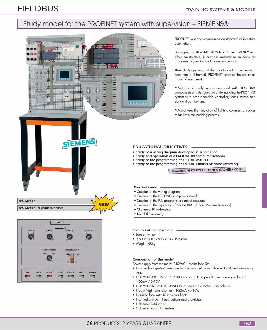
Composition of the modelPower supply from the mains 230VAC – Mains lead 3m.• 1 unit with magneto-thermal protection, residual current device 30mA and emergency
stop.• 1 SIEMENS PROFINET S7-1200 14 inputs/10 outputs PLC with analogue board
4-20mA / 0-10V. • 1 SIEMENS KTP600 PROFINET touch screen 5.7 inches, 256 colours.• 1 Day/Night simulation unit 4-20mA /0-10V.• 1 printed face with 16 indicator lights.• 1 control unit with 4 pushbuttons and 5 switches.• 1 Ethernet RJ45 switch• 6 Ethernet leads, 1.5 metres
Features of the basement• Base on wheels• Dim L x l x H : 750 x 670 x 1950mm• Weight : 60kg
• Study of a wiring diagram developed in automation.• Study and operation of a PROFINET® computer network• Study of the programming of a SIEMENS® PLC.• Study of the programming of an HMI (Human Machine Interface).
PROFINET is an open communication standard for industrialautomation.
Developed by SIEMENS, PHOENIX Contact, MOLEX andother constructors, it provides automation solutions forprocesses, production and movement control.
Through its opening and the use of standard communica-tions media (Ethernet), PROFINET enables the use of allbrand of equipment.
MAQ-SI is a study system equipped with SIEMENS®components and designed for understanding the PROFINETsystem with programmable controller, touch screen andstandard pushbuttons.
MAQ-SI uses the simulation of lighting commercial spacesto facilitate the teaching process.
EDUCATIONAL OBJECTIVES
TEACHING RESOURCES STUDENT & TEACHER / VIDEO
Study model for the PROFINET system with supervision – SIEMENS®
• Creation of the wiring diagram• Creation of the PROFINET computer network• Creation of the PLC programs in contact language• Creation of the supervision from the HMI (Human Machine Interface).• Change of IP addressing• Test of the assembly
Practical works
158
ref. MAQ-NET
KTP600
MAS 0,12KW
PU
ISS
AN
CE
SWITCH
SYSTEME N°1
PARTIE COMMANDE
S7 S8 S9 S10 S11 S12
Bp Int.
I1.0 I1.1 I1.2 I1.3 I1.4 I1.5
PARTIE OPERATIVE
H8
Simulation
H9 H10 H11 H12 H13 H14ACTIONNEURS
Q1.0 Q1.1 Q1.2 Q1.3 Q1.4 Q1.5 Q1.6
fdc7 fdc8 fdc9 fdc10 fdC1 fdc12
I1.6 I1.7 I1.8 I1.9 I1.10 I1.11
Simulation CAPTEURS
!
MA
CH
INE
1
ENTREES
SO
RT
IES
S7-1200
MA
CH
INE
3 PARTIE OPERATIVE
Simulation
I1.6 I1.7
fdc7 fdc8
!
I1.8 I1.9
CAPTEURSfdc9 fdc10
Simulation
Q1.2
H10
Q1.0
H8 H9
Q1.1
ACTIONNEURS
Q1.3
H11
SYSTEME N°3
SO
RT
IES
!
MA
CH
INE
2 PARTIE OPERATIVE
I1.9
fdc10
H11
I1.6 I1.7 I1.8
Simulation
Simulation
Q1.0
fdc7
H8
Q1.3Q1.1 Q1.2
CAPTEURSfdc8 fdc9
H10ACTIONNEURSH9
SYSTEME N°2
ENTREES
PROFINET
PROFIBUSPR
OF
IBU
S
ET200SPROFIBUS
G120
KTP600
MAS 0,12KW
PU
ISS
AN
CE
SWITCH
SYSTEME N°1
PARTIE COMMANDE
S7 S8 S9 S10 S11 S12
Bp Int.
I1.0 I1.1 I1.2 I1.3 I1.4 I1.5
PARTIE OPERATIVE
H8
Simulation
H9 H10 H11 H12 H13 H14ACTIONNEURS
Q1.0 Q1.1 Q1.2 Q1.3 Q1.4 Q1.5 Q1.6
fdc7 fdc8 fdc9 fdc10 fdC1 fdc12
I1.6 I1.7 I1.8 I1.9 I1.10 I1.11
Simulation CAPTEURS
!
MA
CH
INE
1
ENTREES
SO
RT
IES
S7-1200
MA
CH
INE
3 PARTIE OPERATIVE
Simulation
I1.6 I1.7
fdc7 fdc8
!
I1.8 I1.9
CAPTEURSfdc9 fdc10
Simulation
Q1.2
H10
Q1.0
H8 H9
Q1.1
ACTIONNEURS
Q1.3
H11
SYSTEME N°3
SO
RT
IES
!
MA
CH
INE
2 PARTIE OPERATIVE
I1.9
fdc10
H11
I1.6 I1.7 I1.8
Simulation
Simulation
Q1.0
fdc7
H8
Q1.3Q1.1 Q1.2
CAPTEURSfdc8 fdc9
H10ACTIONNEURSH9
SYSTEME N°2
ENTREES
PROFINET
ET200SPROFIBUS
G120
PROFIBUS
PROFINET
PROFINET
ET200SPROFIBUS
ref. LOG-STEP
FIELDBUS
PRODUCTS 2 YEARS GUARANTEE
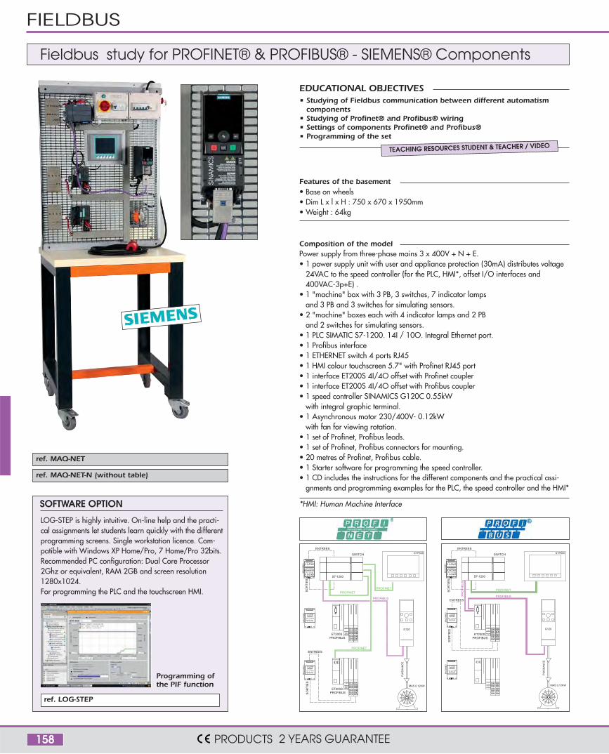
Composition of the modelPower supply from three-phase mains 3 x 400V + N + E.• 1 power supply unit with user and appliance protection (30mA) distributes voltage
24VAC to the speed controller (for the PLC, HMI*, offset I/O interfaces and400VAC-3p+E) .
• 1 "machine" box with 3 PB, 3 switches, 7 indicator lampsand 3 PB and 3 switches for simulating sensors.
• 2 "machine" boxes each with 4 indicator lamps and 2 PBand 2 switches for simulating sensors.
• 1 PLC SIMATIC S7-1200. 14I / 10O. Integral Ethernet port.• 1 Profibus interface• 1 ETHERNET switch 4 ports RJ45• 1 HMI colour touchscreen 5.7" with Profinet RJ45 port• 1 interface ET200S 4I/4O offset with Profinet coupler• 1 interface ET200S 4I/4O offset with Profibus coupler• 1 speed controller SINAMICS G120C 0.55kW
with integral graphic terminal.• 1 Asynchronous motor 230/400V- 0.12kW
with fan for viewing rotation.• 1 set of Profinet, Profibus leads.• 1 set of Profinet, Profibus connectors for mounting.• 20 metres of Profinet, Profibus cable.• 1 Starter software for programming the speed controller.• 1 CD includes the instructions for the different components and the practical assi-
gnments and programming examples for the PLC, the speed controller and the HMI*
SOFTWARE OPTION
LOG-STEP is highly intuitive. On-line help and the practi-cal assignments let students learn quickly with the differentprogramming screens. Single workstation licence. Com-patible with Windows XP Home/Pro, 7 Home/Pro 32bits. Recommended PC configuration: Dual Core Processor2Ghz or equivalent, RAM 2GB and screen resolution1280x1024.For programming the PLC and the touchscreen HMI.
Features of the basement• Base on wheels• Dim L x l x H : 750 x 670 x 1950mm• Weight : 64kg
• Studying of Fieldbus communication between different automatismcomponents
• Studying of Profinet® and Profibus® wiring• Settings of components Profinet® and Profibus®• Programming of the set
EDUCATIONAL OBJECTIVES
TEACHING RESOURCES STUDENT & TEACHER / VIDEO
Fieldbus study for PROFINET® & PROFIBUS® - SIEMENS® Components
ref. MAQ-NET-N (without table)
Programming ofthe PIF function
*HMI: Human Machine Interface

159
ref. MAQ-IP
TRAINING SYSTEMS & MODELS
PRODUCTS 2 YEARS GUARANTEE
ref. MAQ-IP-N (Without table)
Composition of the modelPower supply from mains 230V-2P+E.• 1 power supply unit with user and appliance protection (30mA) distributes voltage
24VAC to the speed controller (for the PLC, HMI*, offset I/O interfaces and230VAC-2p+E).
• 2 "machine" boxes each with 3 PB, 3 switches, 7 indicator lamps and 3 PBand 3 switches for simulating sensors.
• 1 PLC Ethernet 24 inputs /16 outputs• 1 PLC Ethernet 14 inputs /10 outputs• 1 ETHERNET switch 5 ports RJ45• 1 touchscreen HMI 3.8" with Ethernet ports• 1 speed controller ATV32-0.18kW• 1 asynchronous motor 230/400V- 0.12kW with fan for viewing rotation.• 1 multifunction programming graphic terminal with large monochrome screen
(8 lines) 240x160 pixels for programming the speed controller• 1 set of Ethernet leads.• 1 set of Ethernet mounting connectors.• 20 metres of Ethernet cable • 1 software for PLC programming. • 1 Vijéo designer software for programming the HMI.• 1 SoMove software for programming the speed controller ATV32.• 1 DVD includes the instructions for the different components and the practical
assignments and programming examples for the PLC, the speed controller and theHMI* (video).
• Creating an company IP Ethernet network with multiple PCs• Programming a PLC with a built-in or remote Ethernet bus on a TCP/IP interface• Programming a HMI* interface, touch screen, with built-in Ethernet bus• Programming of a speed converter from the So Move software• Interconnecting and settings of components for a global operation• Using the PLC programming software
In the practical works, the sequences of programming of each componentsis provided in the form of video files for a better understanding of the student.
Features of the basement• Base on wheels• Dim L x l x H : 750 x 670 x 1950mm• Weight : 65kg
• Studying of Fieldbus communication between different automatismcomponents
• Studying of the ethernet wiring and IP network creation• Settings of Ethernet components• Programming of the set
Practical works
EDUCATIONAL OBJECTIVES
TEACHING RESOURCES STUDENT & TEACHER / VIDEO
Fieldbus study for ETHERNET - SCHNEIDER® Components
*HMI: Human Machine Interface
*HMI: Human Machine Interface

160
Above HABILIT24-S version, mobile version.Below HABILIT24 version, fixed.Close up on disconnectors, busbar sets andpanel of safety instructions attached to thecabinet bottom.
Cabinet for electrical authorization
Comprises• 1 main source and one secondary source 24VDC distributed on 2 sets of flat copper
busbars, 100A• 2 disconnectors with visible cutting, for padlocking• 2 special circuit-breakers DC 10A• 1 set of protection devices by fuse + RC circuit-breaker 10A-10mA, IS type• 4 gel batteries 12V/14Ah• 3 dual switches• 6 bulkhead lights 24VDC-60W• 1 battery charger 230VAC/24VDC• 1 panel of safety instructions for electrical authorization• 1 2-colour light column indicating 24VDC 'on' and battery recharging• 1 lot of 2 posts + 5m of red and white chain• 1 insulating mat• 1 insulating blanket• 2 removal-from-service padlocks
Practical works• Reminder on electrical authorization• Changing sets of copper busbars• Removing the cabinet from service• Complete the removal from service and authorization documents• Check correct use of PPE• Reading the current in the electrical cabinet using a clamp ammeter
• Put into application the knowledge, rules and methods for certificationfor authorization to electrical hazards
• Carry out practical assignments, wiring tasks relevant to electricalauthorization
• Perform maintenance and cleaning operations in an industrial cabinet• Perform removal from service operations of electrical equipment• Take measurements using a clampammeter
EDUCATIONAL OBJECTIVES
TEACHING RESOURCES STUDENT & TEACHER
The service voltage of 24VDC, protected by fuse and circuit-breaker, makes use of thecabinet completely safe. The integrated load, comprised of six 60W lamps, enables asufficiently significant current to be generated. The cabinet is self-contained and requiresno connection to the mains 230V when in use. A mains cable is nevertheless included forrecharging the batteries using an integral charger.Available in 2 versions, fixed or mobile.
ref. HABILIT24 Fixed version
ref. HABILIT24-S Mobile version with base on wheels
Features• 3-metre mains lead for battery charger• Dimensions: HABILIT24: 450 x 700 x h 2000mm - Weight: 96 kg
HABILIT24-S: 600 x 800 x h 2120mm - Weight: 111 kg
SAFETY TRAINING
PRODUCTS 2 YEARS GUARANTEE
161
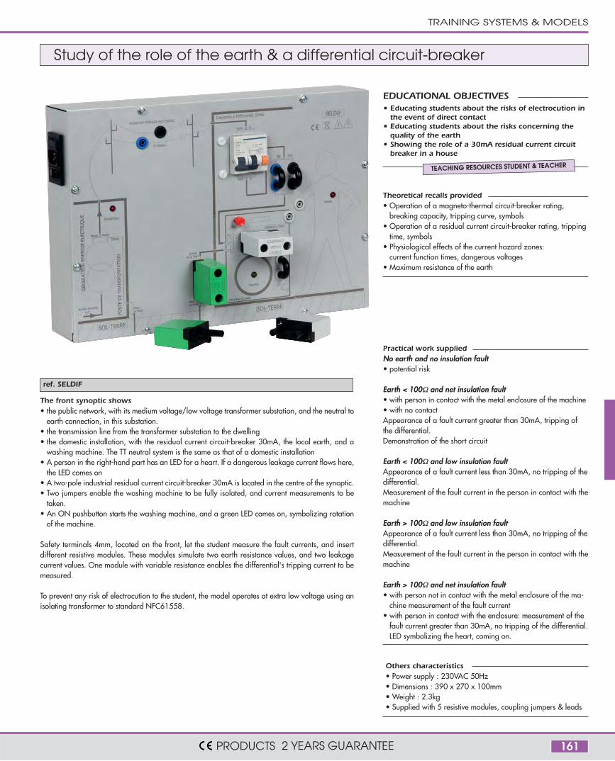
ref. SELDIF
The front synoptic shows• the public network, with its medium voltage/low voltage transformer substation, and the neutral to
earth connection, in this substation.• the transmission line from the transformer substation to the dwelling• the domestic installation, with the residual current circuit-breaker 30mA, the local earth, and a
washing machine. The TT neutral system is the same as that of a domestic installation• A person in the right-hand part has an LED for a heart. If a dangerous leakage current flows here,
the LED comes on• A two-pole industrial residual current circuit-breaker 30mA is located in the centre of the synoptic. • Two jumpers enable the washing machine to be fully isolated, and current measurements to be
taken. • An ON pushbutton starts the washing machine, and a green LED comes on, symbolizing rotation
of the machine.
Safety terminals 4mm, located on the front, let the student measure the fault currents, and insertdifferent resistive modules. These modules simulate two earth resistance values, and two leakagecurrent values. One module with variable resistance enables the differential's tripping current to bemeasured.
To prevent any risk of electrocution to the student, the model operates at extra low voltage using anisolating transformer to standard NFC61558.
Study of the role of the earth & a differential circuit-breaker
Theoretical recalls provided• Operation of a magneto-thermal circuit-breaker rating,
breaking capacity, tripping curve, symbols• Operation of a residual current circuit-breaker rating, tripping
time, symbols• Physiological effects of the current hazard zones:
current function times, dangerous voltages• Maximum resistance of the earth
• Educating students about the risks of electrocution inthe event of direct contact
• Educating students about the risks concerning thequality of the earth
• Showing the role of a 30mA residual current circuitbreaker in a house
EDUCATIONAL OBJECTIVES
TEACHING RESOURCES STUDENT & TEACHER
Others characteristics• Power supply : 230VAC 50Hz• Dimensions : 390 x 270 x 100mm• Weight : 2.3kg• Supplied with 5 resistive modules, coupling jumpers & leads
Practical work suppliedNo earth and no insulation fault• potential risk
Earth < 100Ω and net insulation fault• with person in contact with the metal enclosure of the machine• with no contactAppearance of a fault current greater than 30mA, tripping ofthe differential. Demonstration of the short circuit
Earth < 100Ω and low insulation faultAppearance of a fault current less than 30mA, no tripping of thedifferential.Measurement of the fault current in the person in contact with themachine
Earth > 100Ω and low insulation faultAppearance of a fault current less than 30mA, no tripping of thedifferential.Measurement of the fault current in the person in contact with themachine
Earth > 100Ω and net insulation fault• with person not in contact with the metal enclosure of the ma-
chine measurement of the fault current• with person in contact with the enclosure: measurement of the
fault current greater than 30mA, no tripping of the differential.LED symbolizing the heart, coming on.
TRAINING SYSTEMS & MODELS
PRODUCTS 2 YEARS GUARANTEE

162
ref. TAPIX
OPERATIVE PART ONLY
TAPIX is a conveyor belt for a cash register with the samefeatures as the ones you would find in a supermarket.It comprises a conveyor belt driven by a gear motor, a controlunit used by the cashier, an indicator light showing the status ofthe cash till and start and end of belt sensors.The TAPIX system will only operate once the console has beenconnected to an external electrical cabinet.
MIMIC CONSOLE ALLOWING ELECTRICAL CONNECTION• 1 HARTING ® rapid connector (on the console) for connecting
sensors, the cashier unit and the status indicator light.• 1 set of safety terminals (on the console) bringing together the
wiring for the motor’s terminal board.• This area can take a HARTING® rapid connection interface if
the user does not have any electrical measurements to takefrom the motor.
CASHIER UNIT CONNECTED TO THE CONSOLEIt comprises all of the various controls that the cashier requires.• “Till open” push-button• “Last customer” push-button• “Information request” push-button• 3-position switch:
(1) Forced belt operation:The belt will continue to move forwards.(2) Automatic operation of belt:The belt will move forwards depending on the objects that areplaced on it(3) Switch off belt
STATUS INDICATOR LIGHT CONNECTED TO THECONSOLEIndicates the status of the till to customers• Green = till open• Orange = last customer• White = Call
PHOTO-ELECTRIC CELLS CONNECTED TO THE CONSOLE• Placed at the start and end of the belt, they detect
- the presence of an item on the belt, which in turn activates thebelt- that items are building up at the end of the belt, which in turnshuts down the belt
• These cells are of the NO, dry contact output type
GEAR MOTORThree-phase 230/380V. The motor’s terminal board, whichprotrudes onto the console, enables the user to add an ammeteror a wattmeter in order to measure the current and power.
SET OF CABLESSet of two 3-metre-long cables supplied with TAPIX
Supermarket checkout simulator
Proposed Practical Works• Studying and locating of the different components• Wiring of cells, light signal tower and gearmotor• Making different wirings corresponding to various operating scenarios of the system
Features of the basement• Frame on wheels• Dimensions : 1600 x 650 x 1150mm (Hight without indicator light)• Weight : 60kg
• Understanding, putting into service, getting started and setting of the system• Making different wirings and functioning tests• Illustration and visualization of the result of a PLC program
EDUCATIONAL OBJECTIVES
USER’S MANUAL + PW
TRAINING SYSTEMS
PRODUCTS 2 YEARS GUARANTEE
DEPOSIT AREA (NOT SUPPLIED) CONVEYOR BELT
Cashier unit
Photo-electricscells
Indicator light

163
ref. TAPIX-ARM-GD
FEATURES OF THE POWER CONSOLE• Console which is used for safe testing and supplies the three-phase and 24V power.• Circuit breaker, in front of the power source• General residual current circuit breaker protection.• General emergency stop and Start/Stop• 2 circuit breakers for protecting the three-phase and 24V power supply• Cabinet door safety contact control.
FEATURES OF THE TEST CABINET• 800 x 600 x 250mm steel cabinet• Plate on door with actuators and control lamps wired to the HARTING® connector.• Free spaces for the addition of control accessories DIAM 22.• Rapid hanging and connection of a grid no bigger than 750 x 550mm.• Door safety contact
(power to the cabinet is cut off automatically if the door is opened)• 4 fixed connectors on grid, to be wired by students• 4 rapid connection jacks to the sensors, controls and motor.
KEY-OPERATED DOOR OVERRIDE• Allows the live cabinet to be used with the door open if the switch has been activated.
Operates with a different key to the No.455.
ref. TAPIX-CAB model with wired grid
MONITORING ON TAPIX SYSTEMS ENABLES THE USERTO DISPLAY
• till open information • last customer information• information request details• Presence of items on the belt• The build-up of items on the belt• Motor operation• Mains power on 400V• 24V mains power on TO CONTROL
• till open information •last customer information• information request details• the operation of the motorYou can also create your own monitoring.
REF. TAPIX-S TAPIX-S-T6
PLC programming software • •
Software for touchscreen •
Software for PC •
5.7 inch colour touchscreen •
The systems which include a monitoring function are all suppliedassembled and fully wired. Detailed instructions with full features ofeach component and tutorial supplied.The monitoring is fully developped and operational.
5.7-INCH TOUCHSCREEN COLOUR• High-visibility 256-colour TFT screen• Communication, via RJ45 connector, for the TCP/IP ETHERNET network• Adjustable contrast and brightness• 24V DC/0.3A power supply• Dim. 130 x 104 x 41mm
These versions are identical to TAPIX, only the connec-tion console is replaced by a control panel and a testcabinet. The setting up of the grid is immediate.It’s an autonomous system.4 Harting® connectors connect the grid to the test ca-binet end the control panel. The right panel of the testcabinet is equipped with the buttons and the indicatorlights necessary to the startup of the student’s grid.
Some versions asTAPIX-ARM-GD.It’s an autonomoussystem.
USER’S MANUAL + SUPERVISION PW
MODEL WITH TEST CABINET MODEL WITH TEST CABINET AND MONITORING
TRAINING SYSTEMS & MODELS
PRODUCTS 2 YEARS GUARANTEE

164
Drinking water supply simulator (VijeoDesigner-Schneider®)
SYSTEM DESCRIPTION• 1 150-litre tank simulates the river.• 2 transparent tank (60 L) simulates the settling basin and the water tower
Fitted with 3 water-level sensor (all or nothing).• 2 motorised pumps draws the water (river to the basin / basin to the water tower)• 1 tap drains the water tower.• 2 all or nothing flow sensors.• 1 valve drains the settling basin.• 2 valves at the motorised pump output to adjust the flowrate of the water.• 2 emergency overflows.• 1 test cabinet, with PLC, Analog card and Ethernet...• Protection main control panelwith circuit breakers including one 30mA control
and consignment.
The water that comes out of our taps is drinkable and has travelled a long way.In some cases, it is pumped from rivers and then undergoes various treatmentprocesses before it becomes fit for drinking. It flows into a settling basin, at thebottom of which the heaviest materials are deposited, then it is filtered throughlayers of sand and sterilised, in order to remove bacteria. This clean water is thentransported by means of pipes and pumping before it is stored in a water tower.These provide consumers with a constant pressure. The CHATO system enablesstudents to simulate this entire circuit, from the stage where water is pumped fromrivers to the stage where it arrives in people’s homes.
THE MONITORING ENABLES TO DISPLAY• The water-levels• The settling basin pump feed • The water tower pump feed• Movement of the water from the river into the settling basin • Movement of the water in the settling basin to the water tower
Low water level warning message for each tank
THE MONITORING ENABLES TO CONTROL• the settling basin pump feed manually • the water tower pump feed manually• the cycle start• MANUAL / AUTOMATIC / MAINTENANCE mode
THE MONITORING ENABLES TO SIMULATE• the detection of the 6 water level sensors
BASIN
WATERTOWER
RIVER
TRANSPARENT TANKS MADE FROM UNBREAKABLE LEXAN
Features of the PLC supplied• sequential function chart or ladder language programming• 230V mains power supply.• 14 inputs 24V DC on terminal• 10 binary outputs 230V/2A on terminal• RJ45 Ethernet output, used for connecting the PLC to the IP computer network.• The programming software and index in the form of ladder language
is supplied.
System characteristics• Frame on wheels.• Dim 1500 x 750 x 1970mm.• Weight : 190kg.
TRAINING SYSTEMS
PRODUCTS 2 YEARS GUARANTEE
Setting basin
Treatment
Water tower
Pump
Pump
Distribution

165
ref. CHATO-DEBIT
ref. CHATO-NIV
• Dry-contact horizontal levelsensors.
• max voltage 24V• Max current 3A
FLOW CONTROL VALVES• 1 for setting tank pump• 1 for water-tower pump
Simulates domestic waterconsumption.Connected by hoses to thetank that simulates the river.
Used to drain the tank,e.g. to simulate reservoirmaintenance.
• Simulate the river.• Plastic tank with drain plug.• Installed on a base so it can
be moved with the system.
2 PUMPS• 230/400V 3-phase motor(SINGLE-PHASE UPON REQUEST)• Power 750W• Stainless-steel body and
turbine• Auto-start
PUMPS & FLOW CONTROL VALVES SENSORS
150L TANKDRAIN VALVES TAP
The sensor shows the flowrate of the water on the displayunit when it leaves the pump. Students can observe achange in the flowrate, depending on the valve setting.4-20mA signal output on Ø4mm safety terminals.
Detects water flowing in the PVCpipe of the CHATO circuit. AnNO or NC contact at the sensoroutput sends information to aPLC or a contactor.
ALL OR NOTHING FLOW SENSOR
FEATURES OF THE DIFFERENT COMPONENTS
OPTION FLOWMETER
HYDROSTATIC PRESSURE SENSOR OPTION
This option, supported by the PLC and the monitoringprogram, measures the water level. The monitoringscreen displays the levels in the tanks proportionally tothe pressure. Possibility to install 2 sensors, one on eachtank (Basin / Water tower).• Piezoelectric measuring cell• Scale precision +/- 0.5%• 4-20 mA
REF. CHATO-4S-T6
PLC programming software
Monitoring software VijeoDesigner
5.7 inch colour touchscreen
The monitoring software delivered with the setallows to modify the initial program and to createyour own programming.
REF. CHATO-4S
PLC programming software
Monitoring software VijeoDesigner
The system is the same than in the version above butwithout the touch screen. The monitoring is made onPC with the software SCHNEIDER VijeoDesigner.
MONITORING ON TOUCHSREEN
MONITORING ON PC ONLY
Proposed Practical Works• Setting of the PLC• IP addressing management• Loading, modification, monitoring creation
• Understanding, putting into service, gettingstarted and setting of the system
• Understanding the settings and the program-ming of the PLC
• Know more about the monitoring application
EDUCATIONAL OBJECTIVES
USER’S MANUAL + MONITORING PW
TRAINING SYSTEMS & MODELS
PRODUCTS 2 YEARS GUARANTEE

166
ref. CHATO-4-GD
123456
ABCD
3
4
5
6
A B CED
1
2
E
TECHNICAL FEATURES OF THE CONSOLEConsole which makes testing safe, with control of the cabinet door’s safety contact.
Circuit breaker, in front of the power source
General residual current circuit breaker 30mA.
General emergency stop and Start/Stop
2 circuit breakers for protecting the three-phase and 24V power supply
Open solution to traditional cabling solution in electrical engineering wi-ring.• Door panel prewired• Free spaces for adding some control components (Diam 22mm)• The grid is easy to disconnect due to Harting connectors and plugs for
the level sensors, the moto- pumps and the power supplies 400V and24V.
Version without monitoring
SYSTEM DESCRIPTION• 1 150-litre tank simulates the river.• 2 transparent tank (60L) simulate the settling basin.
Fitted with 3 water-level sensor (all or nothing).• 2 motorised pumps draws the water
(river to the basin / basin to the water tower)• 1 tap drains the water tower.• 2 All or nothing flow sensors.• 1 valve drains the settling basin.• 2 valves at the motorised pump output to adjust the flowrate of the water.• 2 emergency overflows.• 750 x 1500mm base on wheels enables you to move the system• 1 test cabinet not wired.• 1 electric console with control and protection.
DOOR CLOSEDDOOR OF THE CABINET OPENED
TECHNICAL FEATURES OF THE CABINET 800 x 600 x 250mm steel cabinet, supplied with a grid.
DOOR OVERRIDEKey-operated door override switch. Allows the live cabinet to be usedwith the door open if the switch has been activated.Operates with a different key to the No.455.
Plate on door with unwired control lamps and actuators.
Free spaces for the addition of DIAM 22 control components
Rapid connection and hanging of the grid (not exceeding 750 x 750mm).
Door safety contact
Fixed connectors on grid, to be wired by students
Male Harting® connectors to level sensors, to motorised pumps, to the 400
and 24V power sources and to the control panel.
Drinking water supply simulator with electrical cabinet (not wired)
Proposed Practical Works• Wiring of electrical components according the different operating modes• Troubleshooting and maintenance
• Understanding, putting into service, getting started & setting of the system• Wiring of different components and connection
EDUCATIONAL OBJECTIVES
USER’S MANUAL + PW
TRAINING SYSTEMS
PRODUCTS 2 YEARS GUARANTEE
BASIN
WATERTOWER
RIVER
TRANSPARENT TANKS MADE FROM UNBREAKABLE LEXAN

167
ref. CHATO
This unit is plugged directly into the mimic console, transformingthe 12 safety terminals 4mm into a HARTING ® industrial rapid connector
RAPID CONNECTION INTERFACE FOR THE PUMPS
MIMIC CONSOLEAll the connections and measuring are made on this user-friendly mimic console.• 1 male HARTING connector on the left section is connected to the 6 water level
sensors.• A synoptic indicates the function of each connection and the main features of
the system.• 12 safety terminals and 1 earth socket (4mm) are connected to the electrical
windings of the moto-pumps. The student is able to measure the currents witha multimer.CONNECTION BY SAFETY SOCKETS OR BY MEANS OF THE QUICK CONNECTION INTERFACE
• A quick connection interface (4mm terminals / male Harting) is pluggedon 13 connection sockets for the connection to a control cabinet (not supplied).A detailed synoptic on the interface shows the function of each connection.
SYSTEM DESCRIPTION• 1 150-litre tank simulates the river.• 2 transparent tanks (60L) simulates the settling basin and the water tower.
Fitted with 3 water-level sensors (All or Nothing).• 1 moto-pump draws the water from the “river” to the “basin”.• 1 moto-pump draws the water from the “river” to the “water tower”.• 1 tap simulates the water consumption.
The water flows from the “water tower” to the “river”.• 1 valve drains the settling basin.
Flow rates are adjusted by 2 valves at the output of moto-pumps.• 2 safety overflows devices on the upper parts of tanks avoid any overflow.• 1 set of 2 cables (3m) equipped with female Harting connector can connect the
operative part on your connection box of a control unit.• 750 x 1500mm base on wheels enables you to move the system easily.• 1 mimic console + quick connection interface.
Set of 2 3-metre-long cables supplied with CHATO.• 1 interconnection cable for sensors• 1 interconnection cable for motors
SET OF 2 CABLES
BASIN
WATERTOWER
TRANSPARENT TANKS MADE
FROM UNBREAKABLE LEXAN
RIVER
Drinking water supply simulator (operative part only)
TRAINING SYSTEMS & MODELS
PRODUCTS 2 YEARS GUARANTEE

168
ref. CHATO-PAN
ref. CO-DEB
ref. FLO-DEB
Ref. CHATO-4S-T6 Ref. CHATO-4S Ref. CHATO-4-GD Ref. CHATO
ref. CHATO-AUTO
ref. CHATO-REL
ALL OR NOTHING FLOW SENSOR GRID & PLATE FOR PLCS
GRID & PLATE FOR RELAY
FAULT SIMULATOR UNIT
FLOW INDICATOR WITH FLOAT
Options for drinking water supply simulator CHATO-4 & CHATO
Unit with concealed switches to simulate sensor faults.6 switches linked to 6 sensors.Unit fixed onto the system’s frame.
Detects water flowing in the PVC pipe of the CHATO circuit.An NO or NC contact at the sensor output sends informationto a PLC or a contactor.Features• Can be fitted in any position• PVC connection Diam: 40mm to be stuck on• Switchable, potential-free contact• NO or NC 1A/230VAC• Electrical connection via a DIN connector
A moving float in a transparent tubeindicates the pump’s water flowratein cubic meter/hourFeatures- Upright fitting- Measuring scale: 0.6 to 6 cubic meter/hour- Ascending fluid- Float and stop- PVC connection Diam: 40mm (to be stuck on)
SUMMARY AND HELP IN THE SELECTION OF THE DIFFERENT CHATO SYSTEMPRESENTED PAGES 164 TO 167
Simulator with electricalcabinet and monitoringon touchscreen
Simulator with electricalcabinet and monitoringon PC only
Simulator withelectrical cabinet
Operative part only
Wired door plate and grid for system operation with a PLC.Supplied with programming and training software.
Wired door plate and grid for system operation with relay.
TRAINING SYSTEMS
PRODUCTS 2 YEARS GUARANTEE

169
ref. ASMAT
ref. AUTOMASC
WORKS WITH YOUR OWN PLC
INTERFACE WITH BUILT-IN PLC
ref. ASC89-24 LOGIC CONTROLS IN 24V
ref. ASC89-05 LOGIC CONTROLS IN 5V
Didactic liftThe ASC89 lift is a model which may be connected to a PLC or any microprocessor system.It comprises 24 outputs and 21 inputs.You can only use a part of input/outputs if you want to do easy programmes
MAIN FEATURES :• Opening and closing of the doors on each floor is done by electric servo motors.• The rear of the lift is visible through the sides and the bottom which are transparent• The route of the lift is sensed at each floor by a photo-detectors.• Two limit switches, high & low, (without program control) stop the lift if there is an error in the program.• All of the buttons and switches are fitted with de-bounce circuits.• The outputs are protected against the possibility of a short-circuit.• The rear sliding door is of a transparent Plexiglass design and there is no manual access possible,
as there is risk of damaging the servomotor.
The mechanical controls are sturdy and can withstand any likely faults.
AUTOMASC is delivered in a plastic box including:• a 30 inputs / 26 outputs PLC (dry contacts)• a USB connection interface with the PC• supplies for the PLC outputs• All cables to the lift, mains cable.It is connected to the lift rear connectors with 2 flat cables, one for inputs, the other one for outputs.PROGRAMMINGUser can program AUTOMASC with 2 languages: Instructions list or contact language. You can program itfrom PC, using the software (included). Delivered with a program designed for complete functioning of the lift.OTHER FEATURESThe front panel is transparent to see many LED, showing the PLC state. AUTOMASC is supplied with a demoprogram, which can be modified or completed. The technical leaflet indicates the corresponding between thelift inputs and outputs and the ones of the PLC, allowing the development of a complete program.Mains: 230/240V - 50Hz - 50VA - Dimensions: 250 x 180 x 175 mm - Weight: 2.7kg
ASMAT is an interface allowing a quick connection to the ASC89 lift from a PLC. To help in quickly identifyingthe functions of the connectors, small symbol and piece of text next to each connector, allowing immediateunderstanding of its function. The operating sense: Lift - PLC or PLC - Lift. It is clearly indicated by vertical arrows.Metal box: 22 x 272 x 32mm. Weight: 250g.
4 LEVELSEACH LEVEL HAS
1 electrically opening door - 1 photo-detector for ‘door closed’ - 1 photo-detector for ‘door-open’2 safety limit switches for door open/close (No control from the program possible)1 button to call the lift ‘up’ (except the 3rd floor) with indicator lamp.1 button to call the lift ‘down’ (except the ground floor) with indicator lamp1 lamp to indicate the presence of the lift - 1 photodetector to indicate the presence of the lift
CONTROLS INSIDETHE LIFT
4 buttons for each floor - 1 stop button1 switch to simulate a blocked door4 lights for each floor - 1 light inside the lift (simulating the lighting)
UNIT SUPPLIESPOWER TO
the motors - the LED - internal logic to the unit.
OTHERSSPECIFICATIONS
Dims 780 x 480 x 440mm Weight 15kg Supply 230V 50HzThe unit is available in two driving logic values, 24V or 5V.
CONNECTION CONNECTIONASMAT - LIFT ASMAT - PLCTwo flat cables with: Oneconnector for the inputs andthe other for the outputs.
The front face of the board has two columns of 4mm plugs, which are used toconnect to the PLC with normal leads. The plugs on the left are for theinputs to the PLC, on the right for the outputs.
INTERFACES FOR DIDACTIC LIFT (CHOOSE ONE OF THEM)CHOICE N°1
CHOICE N°2
USER’S MANUAL + 7 PRACTICAL WORKS
PLC which can control the 24V lift via ASMAT interface. Réf. M221-MAX see page 172.
TRAINING SYSTEMS & MODELS
PRODUCTS 2 YEARS GUARANTEE

170
ref. PO-PB2 ref. PO-PC1
• Double casement• Current consumed 0.8A• Max power 200W.• Speed reduction ratio 1/296
• Sliding• Current consumed 1.5A• Max power 290W.• Speed reduction ratio 1/30
• Understanding, putting into service, getting started and setting of a automatic or semi-automatic portal• Interconnecting of the different components in jumper wires mode
EDUCATIONAL OBJECTIVES
USER’S MANUAL + 4 PRACTICAL WORKS
Motorized gates
TRAINING SYSTEMS
PRODUCTS 2 YEARS GUARANTEE
Components involved in the automatic operations(common to both gates)• 1 frame on wheels with brake.• 1 or 2 gear motors, depending on the selected automatic operation model.• 2 pairs of photoelectric cells, to secure the opening and closing of the gate.• 1 unit fitted with an electronic card controls the operation of all of the different settings
(such as closure time-delay, activating the remote control, etc.).• 1 gate opening and closing remote control• 1 gate operation indicator light.• 3 consoles, consisting of 4mm safety terminals for the 230V and 2mm for the extra-
low voltage, containing the wiring for:- the key-operated “gate opening and closing” push-button- the gear motor(s), the light, the 24V power supply for the cells and the
mains power supply- for the 4 photoelectric cells
• 1 fault simulator unit enables the user to create a malfunction in the photoelectric cells.• 1 set of keys for unlocking the door mechanically.
Features common to both gates• Emergency stop circuit breaker• 230V AC mains power supply• Power supply to photoelectric cells: 24V AC. (internal power supply).• Fault simulator unit with 4 circuit breakers, causing a fault on each cell.• Life-time pre-lubrication using grease. • Dimension of the unit: 1400 x 800 x 1700mm / Weight 90kg• Sold with all connection diagrams and all the various settings to be entered for
the smooth operation of the gates.
Tutorials are supplied with automatic functions• Wiring of all of the components• Adjusting the various operating settings• Measuring the properties of gear motors and comparing these values with the
ones for the rating plate. • Looking for one or more faults

171
ref. PRESS-35
The model is delivered ready for use (the electric part is completely wired and allthe pneumatic connections made). The quick-fit joints allow dismounting/reas-sembly of pneumatic interconnections with Ø4mm tubes of various colors.A manual gives details of the operation of all the electro-pneumatic componentsused and their adjustment. Several cycles are described, including one completewith its grafcet.
MANUAL CONTROL BOX SUPPLIED
This box contains• 9 push buttons corresponding
to each actuator• 11 indicator lights which give information
about the state of the sensorsIt allows very slow observation of pneumaticphenomena and learning about the basicregulation of flow control, actuator speed,and detector positions.
ref. PNEU99 with PLC and software
ref. PNEU98 without PLC
• Introduction to pneumatic components• Programming approach by PLC• Monitoring of the system in manual or automatic mode
EDUCATIONAL OBJECTIVES
USER’S MANUAL & THEORETICAL COURSES
OPERATING CYCLEThe parts placed on the conveyor belt are held by the vacuum suction grip of a firstpneumatic jack, then placed on the horizontal jack, grasped by the electromagnetjack undergoing a complete handling cycle before being returned to the belt.
PNEUMATIC COMPONENTS• 3 double effect pneumatic jacks Ø32mm. Travel 250mm, each equipped with:
- flow reducers allowing fine adjustment of their movement- magnetic position detectors (2 or 3 per actuator) with LED- quick-fit joints for Ø4mm tubes
• 2 5/2 electropneumatic distributors• 1 5/3 electropneumatic distributor
All distributors are fitted with- 24V DC coils- LED visual display of the state of the coils- quick-fit joints for Ø4mm tubes- fitted on mountings with silencers
• Vacuum generatorOne of the actuators is fitted with a suction grip with its vacuum system.An adjustable threshold vacuostat delivers an electrical presence or absenceof vacuum signal.A vacuometer allows visual checking on the vacuum.
• Jacks protectionTo avoid any risk of destroying a pneumatic jack, an entirely pneumatic logicsystem (without student access) prevents the simultaneous movement of thehorizontal jack with a vertical jack.
ELECTRIC BOX• Contains a regulated 24V DC 2A source to feed the PLC if necessary if it does
not have an internal supply. The necessary supplies to the model.• A Start cycle button, a Stop cycle button,• a reset button.• a general emergency button stopping the electric and pneumatic supplies.• The connector which the user connects to the PLC or to the manual control box.
USER’S PROTECTION• A transparent color door is a barrier between the pneumatic jacks and the
user’s hand. The opening turns off the air pressure
PLC (only for PNEU99 version)• 14 inputs / 10 outputs (RELAYS)• 2 languages : Grafcet instructions, contact language.• Programming : from a PC using a software (included).• Delivered with a complete and functional program.
OTHER CHARACTERISTICSThe conveyor belt is either controlled by the automatic system and the end of beltdetection switch or by being forced into operation. An electromagnet illustratespicking up by a magnetic field. PNEU** is connected to the air network by splinedterminal placed on the valve block of stop + regulator + filter + distribution outputby quick coupling. PNEU** is delivered on a 1000 x 750mm chassis with lateralfixing brackets on a table.
Pneumatic handling line
TRAINING SYSTEMS & MODELS
PRODUCTS 2 YEARS GUARANTEE
OPTION COMPRESSOR

172
MAT-BOX
AUTO-PRO-A
AUTO-238-A
Integrated PLC units
Integrated touchscreen units
Ref. MAT-BOX AUTO-221 AUTO-221-A 221-MAX
Brand SIEMENS SCHNEIDER
Model SIMATIC S7-1200 M221
Number of Inputs 14 inputs 24VDC 30 inputs 24VDC
Number of outputs10 All or Nothing outputs2A max on resistive load
10 All or Nothing outputs2A max
26 All or Nothing outputs2A max
Analog2 inputs 0-10VDC
1 output 0-10VDC or 4-20mAno
2 inputs PT1001 output 0-10VDC or 4-20mA
2 analog inputs 0-10V
Ethernet yes + 1 mini switch 4 ports RJ45 yes
Software LOG-STEP (in option) SoMachine Basic (supplied)
Power supply 230VAC-50/60Hz by means of socket unit+ switch
Dimensions 330 x 200 x 80mm 330 x 200 x 80mm 380 x 280 x 180mm
Supplied with
1 Ethernet RJ45 3-m cable.6 detailed practical works
(PLC configuration, use andprogramming.)
1 Ethernet RJ45 3-m cable.1 USB cable PC/PLC
Ref. TOUCH-BOX STU-BOX4 STU-BOX6
Brand SIEMENS SCHNEIDER
Modèel Simatic KTP600 HIMISTU
Touchscreen 5,7’’ TFT 256 colours 3,5’’ 65536 colours 5,7’’ 65536 colours
Resolution 320 x 240 pixels
Ethernet 1 RJ45 connector 6 RJ45 connectors (Including 1 5 ports switch) 1 RJ45 connector
USB - 1 USB connector
Software LOG-STEP (in option) VijeoDesigner (supplied)
Power supply 230VAC-50/60Hz by means of socket unit + switch
Dimensions 330 x 200 x 80mm
Supplied with1 Ethernet RJ45 3-m cable.User’s manual with tutorials.
1 Ethernet RJ45 3-m cable.
PLC UNITS
PRODUCTS 2 YEARS GUARANTEE

173
ref. LOG-STEP ref. UNITY-SMALL ref. SOMACHINE
TOUCH-BOX
STU-BOX4
STU-BOX6
For PLCAUTO-PROAUTO-PROA
For PLCMAT-BOXFor TouchscreenTOUCH-BOX
For PLCAUTO-238AUTO-238AAUTO-221AUTO-221-A221-MAX
SOFTWARE OPTIONS
Very intuitive, it proposes an online help andtutorials allowing the user to start quicklywith the different programming screen.
Very intuitive, it allows a multitaskingprogramming. It can convert easily yourprograms made under PL7.
Effective and open professional softwaresolution wich includes Vijeodesigner.Include the programming of controlers andHMI interface (Human Machine Interface)
Réf. AUTO-PRO AUTO-PROA AUTO-238 AUTO-238-A
Brand SCHNEIDER
Model MODICOM M340 M238
Number of Inputs 16 isolated inputs 24Vcc 14 inputs 24V
Number of outputs 16 outputs 2A max - TOR 6 all or nothing outputs + 4 static outputs (24V)
Analog -
4 voltage / current inputs±10V / 0-10V / 0-5V / 1-5V / ±5V
0-20mA / 4-20mA / ±20mA2 voltage / current outputs±10V / 0-20mA / 4-20mA
-2 inputs 4-20mA / 0-10Vcc1 output 4-20mA / 0-10Vcc
Ethernet Ethernet module TCP/IP on RJ45 1 Ethernet port + 1 Modbus port 1 Ethernet port
Software UNITY SMALL (in option) SoMachine (in option)
Power supply 230VAC-50/60Hz by means of socket unit + switch
Dimensions 360 x 270 x 170mm 330 x 200 x 80mm
Supplied with1 ethernet RJ45 3-m cable. 1 ethernet RJ45 3-m cable.
1 USB cable.
TRAINING SYSTEMS & MODELS
PRODUCTS 2 YEARS GUARANTEE

174
ref. ZELIO-201-24 ref. ZELIO-NET
BASIC MODEL MODEL WITH TCP-IP ETHERNET MODULE
This unit is a programmable interface working as a PLC with orders (inputs) andcontacts (outputs). Its particularity is to integrate a clock which sets controls. Itsprogramming software is very easy to use. Among its various and user-friendlyfunctions, the function "SIMULATION" which allows to check the program beforeusing it in real condition.Dimensions of the box: 360 x 270 x 170mm
Sum up of functions and possibilities of the unit and its software:• 12 inputs 24V DC, 6 can be wired in analog inputs 0-10V• 8 dry contacts outputs• a display indicating state and local programming • 6 keys for local programming
The multilanguage software also has :• 3 programming languages• a good viewing of clock settings• a free keyboarding of associated comments for the follow up of steps.• a simplified communication between the unit and the PC (serial connection)• a direct display of the text on the unit display• a visualization of outputs state• an input/output computer simulation by a simple click on the mouse.
Help function for userBesides its help function always available as a Search Menu, the software hasa demo video functioning like a VCR. Short films show the main steps forprogramming the system.
We have added to the ZELIO-201-24 (opposite) a network communication modulewhich can be used to connect the ZELIO to the Ethernet using the Modbus TCPprotocole
Ethernet module features:• direct connection to the ZELIO• female RJ45 reinforced cable • a communication display LED (LK/ACT 10/100)• a STATUS display LED (STS)
SOFTWARE SUPPLIED WITH ZELIO-201-24 AND ZELIO-NET
Programmable controls system
PLC UNITS
PRODUCTS 2 YEARS GUARANTEE

175
ref. PUP-PLC
ref. MAQ-VISION
Simulator for checking controller (PLC) programming
Quality control system by vision sensor
Composition of the console• 1 Start / Stop button with indicator light (general control)• 1 magneto-thermal + RC circuit-breaker 30mA• 3 pushbuttons NO• 3 pushbuttons • 2 ON/OFF switches NO• 2 ON/OFF switches • 1 wind sensor, binary contact• 1 light sensor, binary contact• 3 limit switches NO• 1 Temperature sensor PT100, 3-wire output• 1 voltage generator adjustable by potentiometer from 0 to 10VDC
• 1 current generator adjustable by potentiometer from 4 to 20mA• 1 dimmer 230VAC with control 0-10VDC• 1 dimmer 230VAC with control 4-20mA• 1 buzzer 24VDC• 2 3-pole contactors 24VAC + 2 auxiliary contacts NO• 3 green indicator lights 24VAC• 3 red indicator lights 24VAC• 1 source of fixed voltage 230VAC 50Hz• 1 source of fixed voltage 24VDC• 1 source of voltage 24VAC 50Hz• 1 carrying handle
Checking a PLC program requires the connection of an operative part.PUP-PLC groups together a set of actuators, power supplies and components required for checking programs.Its complete composition provides great comfort for this check.
Features• 3-metre mains lead for power supply 230V-50/60Hz single phase.• Console dimensions: 1000 x 160 x h 300mm. Weight: 14kg.
Composition of the model• Power supply unit, magneto-thermal protection device
and indicator light.• Motorized conveyor belt 24VDC.• Colour vision sensor on height and tilt adjustable support.• Binary position sensor.• Indicator light for "nonconform part".• 1 Configuration software.• 2 part samples, conform and nonconform.
MAQ-VISION is a model equipped with a vision sensor combined with configuration software forpart surveillance and recognition by video. This type of automatic visual quality control is nowadaysused on many production lines. It enables the checking of parameters like presence, position, orien-tation, sorting, integrity and marking. It is also used for guiding before gripping. The image of thereference part and its acceptance tolerances are saved in the sensor's memory. The "good part" or"bad part" result is obtained from "binary" outputs.MAQ-VISION is equipped with a motorized conveyor belt 24VDC. It carries the part under the sensorfor checking. An indicator light signals if the part is conform or not.Supplied with the video recognition programming software.
Features• 2-metre mains lead for power supply.• Dimensions of the housing: 240 x 180 x h 130mm.• Dimensions of the conveyor belt: 300 x 110 x 120mm.
Practical works proposed• Carry out the configuration and programming of the video sensor
using the software• Creation of the wiring diagram• Wiring of the conveyor belt, vision sensor and position sensor• Testing with different part samples
• Study and putting into service of a quality control systemby vision sensor
• Creating the wiring for motorized conveyor belt and videoand position sensors
• Using video recognition programming software
EDUCATIONAL OBJECTIVES
TEACHING RESOURCES STUDENT & TEACHER
TRAINING SYSTEMS & MODELS
PRODUCTS 2 YEARS GUARANTEE

176
ref. MAQ-LIGHT
Managing of hypermarket lighting by supervision
Large floor area buildings, like supermarkets, require a lot of lighting.The control of this lighting is a real economic and ecological issue whichrequires thinking about the concept of zoning and presence.MAQ-LIGHT offers the study of this need through controllers (PLC) andsupervision controlled by 2 touch screens.The presentation with two-sided vertical panels on a wheeled frameprovides an ergonomic view of the zones to be controlled.
Comprises• 1 unit with magneto-thermal, RC protection devices
& emergency stop.• 3 SCHNEIDER® Ethernet PLCs• 1 Ethernet colour touch screen HMIS5T 3.5"• 1 Ethernet colour touch screen HMIS5T 5.7"• 1 presence detector• 1 Day / Night simulation unit with potentiometer• 1 engraved face defining the 3 lighting zones
Face equipped with 16 indicator lights simulating the light points• 3 control units with 7 pushbuttons and 7 indicator lights• 1 Ethernet RJ45 switch• 6 Ethernet leads, 1.5 metres
Practical works• Creation of the architectural diagram of the electrical installation• Creation of the computer Ethernet• Creation of PLC programs in contact language• Creation of the supervision from the two touch screens• Change of IP addressing• Testing the assembly
• Study and putting into service of a lighting management systemfor hypermarket by supervision
• Studying the configuration of an Ethernet type computer network• Studying the programming of a PLC in contact language• Studying the programming of an HMI (Human Machine Interface)• Studying the coexistence of several PLCs and HMIs
EDUCATIONAL OBJECTIVES
TEACHING RESOURCES STUDENT & TEACHER
Features of the unit• Power supply 230VAC by 3-metre mains cord• Dimensions: 750 x 670 x h 1950mm• Weight: 64 kg
Front view Rear view
PROGRAMMING SYSTEM
PRODUCTS 2 YEARS GUARANTEE

177
ref. TA11
TA11 is a study system used to regulate the CO2 level in a motorwaytunnel. It consists of a fan for air renewal and an electrical cabinet grou-ping the regulation system components. The cabinet and fan are placedon a wheeled frame and connected by a 5m cable.Complete unit supplied ready for operation with monitoring.The PLC is supplied as well as the monitoring programand wiring diagrams.Are also supplied: The Teachers/Students tutorials on PLC programming,monitoring, the Ethernet network, analogue regulation.
OperationOn the cabinet's door, a potentiometer simulates the CO2 level in thetunnel. Depending on the CO2 level, the PLC controls the fan’s rotationspeed and plans the access to the 4 traffic lanes represented by 8indicator lights positioned above the cabinet. A stand-alone fire sensorindicates there is a fire in the tunnel An electronic buzzer warns that theCO2 level is too high. An anemometer fixed in the fan's air flow controlsthe rotation. This regulation system is PC monitored via the Schneider®software supplied.
The main cabinet components• 1 Schneider® PLC• 1 2.2kW speed controller • 1 analogue card controls the 4-20mA or 0-10V speed controller
signal.• 1 Ethernet card is used to connect the entire system to an IP
computing network such as, for example, the establishment’snetwork to monitor operations from a remote computing room.
• Controls on the front of the door:General Start/Stop buttonEmergency stopCO2 level potentiometerAuto/ManualFan Start/Stop buttonPotentiometer for the fan air flowWarning buzzer if excessive CO2 levelRJ45 connector for the PC linkElectrical protective devices for users and equipment.
Monitoring functions on the PC screenDisplay on digital displays and by curves • CO2 level and air flow in the tunnel• number of open or closed traffic lanes• presence of a fire in the tunnel• controls access to each traffic lane• regulates the fan air flow• triggers the fire alarm• select the Auto or Manual operating mode
Monitoring
software
program
PLC
program
Monitoring
from a PC
Ventilation control and tunnel access
Proposed Practical Works• PLC programming• Loading, modification, creation of a supervision program• Ethernet network configuration• Analysis of the regulation
• Studying, putting into service, getting started and settingof the system
• Understand the setting and the programming by PLC• Understanding and use of a supervision• Practical approach of analog inputs
EDUCATIONAL OBJECTIVES
USER’S MANUAL + TUTORIALS + MONITORING
Features of the unit• Wheeled frame 750x670mm• Total height: 1870mm• Powered by a 400V three-phase hypra socket • 1000VA Fan, 96m3/min maximum flow rate,
400V 3-phase, Ø 400mm.
TRAINING SYSTEMS & MODELS
PRODUCTS 2 YEARS GUARANTEE
178
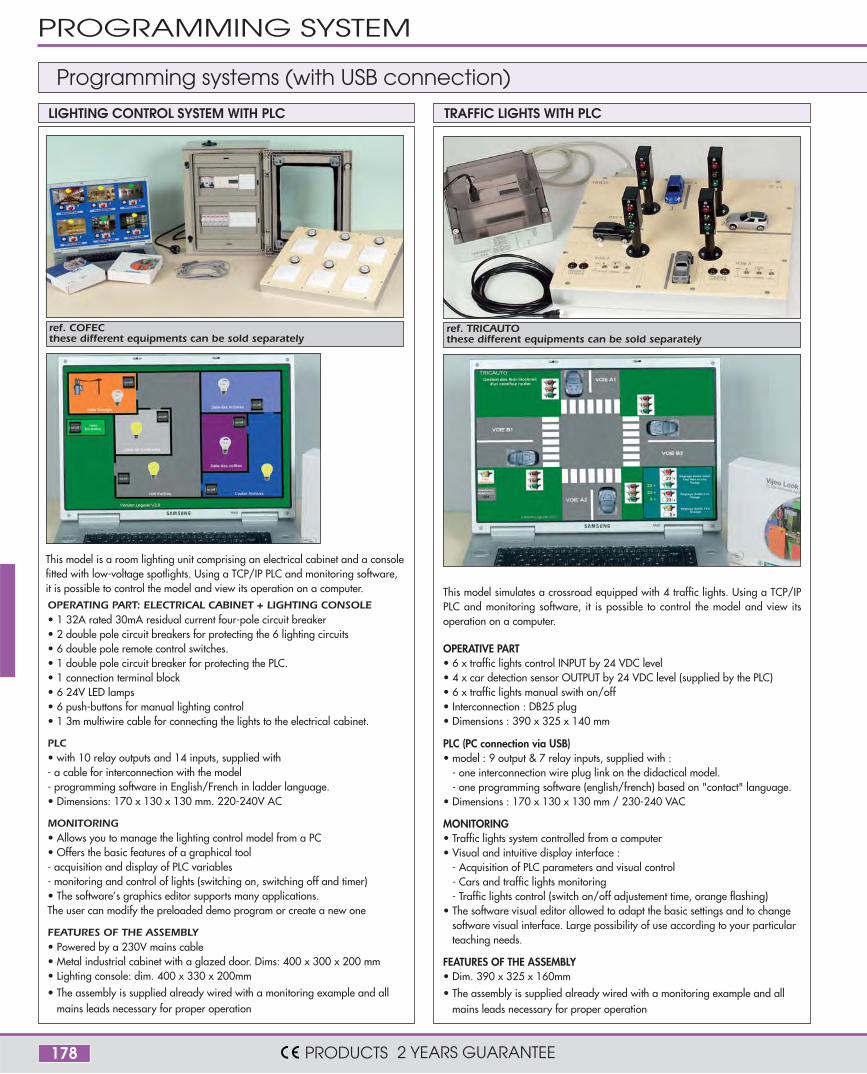
This model is a room lighting unit comprising an electrical cabinet and a consolefitted with low-voltage spotlights. Using a TCP/IP PLC and monitoring software,it is possible to control the model and view its operation on a computer.OPERATING PART: ELECTRICAL CABINET + LIGHTING CONSOLE• 1 32A rated 30mA residual current four-pole circuit breaker• 2 double pole circuit breakers for protecting the 6 lighting circuits• 6 double pole remote control switches.• 1 double pole circuit breaker for protecting the PLC.• 1 connection terminal block • 6 24V LED lamps• 6 push-buttons for manual lighting control• 1 3m multiwire cable for connecting the lights to the electrical cabinet.
PLC• with 10 relay outputs and 14 inputs, supplied with - a cable for interconnection with the model- programming software in English/French in ladder language.• Dimensions: 170 x 130 x 130 mm. 220-240V AC
MONITORING• Allows you to manage the lighting control model from a PC• Offers the basic features of a graphical tool- acquisition and display of PLC variables- monitoring and control of lights (switching on, switching off and timer)• The software’s graphics editor supports many applications.The user can modify the preloaded demo program or create a new one
FEATURES OF THE ASSEMBLY• Powered by a 230V mains cable• Metal industrial cabinet with a glazed door. Dims: 400 x 300 x 200 mm• Lighting console: dim. 400 x 330 x 200mm
• The assembly is supplied already wired with a monitoring example and allmains leads necessary for proper operation
ref. COFEC these different equipments can be sold separately
ref. TRICAUTO these different equipments can be sold separately
OPERATIVE PART• 6 x traffic lights control INPUT by 24 VDC level• 4 x car detection sensor OUTPUT by 24 VDC level (supplied by the PLC)• 6 x traffic lights manual swith on/off• Interconnection : DB25 plug• Dimensions : 390 x 325 x 140 mm
PLC (PC connection via USB)• model : 9 output & 7 relay inputs, supplied with :
- one interconnection wire plug link on the didactical model.- one programming software (english/french) based on "contact" language.
• Dimensions : 170 x 130 x 130 mm / 230-240 VAC
MONITORING• Traffic lights system controlled from a computer• Visual and intuitive display interface :
- Acquisition of PLC parameters and visual control- Cars and traffic lights monitoring- Traffic lights control (switch on/off adjustement time, orange flashing)
• The software visual editor allowed to adapt the basic settings and to changesoftware visual interface. Large possibility of use according to your particularteaching needs.
FEATURES OF THE ASSEMBLY• Dim. 390 x 325 x 160mm
• The assembly is supplied already wired with a monitoring example and allmains leads necessary for proper operation
This model simulates a crossroad equipped with 4 traffic lights. Using a TCP/IPPLC and monitoring software, it is possible to control the model and view itsoperation on a computer.
LIGHTING CONTROL SYSTEM WITH PLC TRAFFIC LIGHTS WITH PLC
Programming systems (with USB connection)
PROGRAMMING SYSTEM
PRODUCTS 2 YEARS GUARANTEE
179
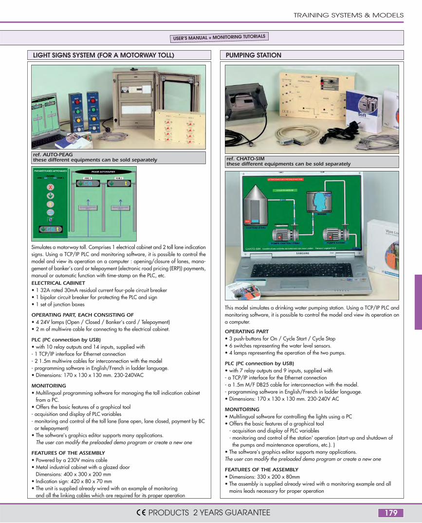
ref. AUTO-PEAG these different equipments can be sold separately ref. CHATO-SIM
these different equipments can be sold separately
Simulates a motorway toll. Comprises 1 electrical cabinet and 2 toll lane indicationsigns. Using a TCP/IP PLC and monitoring software, it is possible to control themodel and view its operation on a computer : opening/closure of lanes, mana-gement of banker’s card or telepayment (electronic road pricing (ERP)) payments,manual or automatic function with time-stamp on the PLC, etc.ELECTRICAL CABINET• 1 32A rated 30mA residual current four-pole circuit breaker• 1 bipolar circuit breaker for protecting the PLC and sign• 1 set of junction boxes
OPERATING PART, EACH CONSISTING OF• 4 24V lamps (Open / Closed / Banker’s card / Telepayment)• 2 m of multiwire cable for connecting to the electrical cabinet.
PLC (PC connection by USB)• with 10 relay outputs and 14 inputs, supplied with - 1 TCP/IP interface for Ethernet connection- 2 1.5m multiwire cables for interconnection with the model- programming software in English/French in ladder language.• Dimensions: 170 x 130 x 130 mm. 230-240VAC
MONITORING• Multilingual programming software for managing the toll indication cabinet
from a PC. • Offers the basic features of a graphical tool- acquisition and display of PLC variables- monitoring and control of the toll lane (lane open, lane closed, payment by BC
or telepayment)• The software’s graphics editor supports many applications.
The user can modify the preloaded demo program or create a new one
FEATURES OF THE ASSEMBLY• Powered by a 230V mains cable• Metal industrial cabinet with a glazed door
Dimensions: 400 x 300 x 200 mm• Indication sign: 420 x 80 x 70 mm• The unit is supplied already wired with an example of monitoring
and all the linking cables which are required for its proper operation
OPERATING PART • 3 push-buttons for On / Cycle Start / Cycle Stop• 6 switches representing the water level sensors.• 4 lamps representing the operation of the two pumps.
PLC (PC connection by USB)• with 7 relay outputs and 9 inputs, supplied with - a TCP/IP interface for the Ethernet connection- a 1.5m M/F DB25 cable for interconnection with the model.- programming software in English/French in ladder language.• Dimensions: 170 x 130 x 130 mm. 230-240V AC
MONITORING• Multilingual software for controlling the lights using a PC• Offers the basic features of a graphical tool
- acquisition and display of PLC variables- monitoring and control of the station' operation (start-up and shutdown of
the pumps and maintenance operations, etc.). )• The software’s graphics editor supports many applications.The user can modify the preloaded demo program or create a new one
FEATURES OF THE ASSEMBLY• Dimensions: 330 x 200 x 80mm• The assembly is supplied already wired with a monitoring example and all
mains leads necessary for proper operation
This model simulates a drinking water pumping station. Using a TCP/IP PLC andmonitoring software, it is possible to control the model and view its operation ona computer.
LIGHT SIGNS SYSTEM (FOR A MOTORWAY TOLL) PUMPING STATION
USER’S MANUAL + MONITORING TUTORIALS
TRAINING SYSTEMS & MODELS
PRODUCTS 2 YEARS GUARANTEE