tracking system for a safety harness system - tu/e
TRANSCRIPT

Tracking system for a SafetyHarness System
ing. M. van Leeuwen
DCT 2007.088
Supervisor: Prof.dr.ir. M.SteinbuchCoach: dr.ir. S.K. Advani
Technische Universiteit EindhovenDepartment Mechanical EngineeringDynamics and Control Technology Group
Eindhoven, June, 2007

ii

Abstract
The Toronto Rehabilitation Institute (TRI) in combination with the university of Toronto are develop-ing the challenging Environment Asset Laboratory (CEAL) as part of a large research infrastructureupgrade program. The CEAL-simulator consist out of a six-degrees-of-freedom (six-DOF) simulationplatform. On this platform researchers are able to investigate stability and balance of normal and dis-abled persons. Subjects will be placed on this platform and the simulation/motion system will causethe platform to move. These motions may vary from slow movements, steady state tilting of the plat-form and rapid movements.
Since the subjects will be performing their tasks on the moving platform, safety is a critical issue inthis program. The subjects are generally older and impaired people who have suffered a stroke or aninjury. Their safety is the critical aspect in the project. To prevent the subjects to become injured, asafety harness system is required to protect the subjects against the hazards of falling.
During this internship there is searched for the optimal solution for tracking a person on the platform.The current concept for the safety harness system is a XY-guidance mounted onto the platform. Thesafety systemmust track the motion of the subjects onto the platform. Goal of this internship is to findthe optimal solution for this tracking problem. This is achieved by chronological treating the followingaspects:
• Requirements, setting up a list with al the relevant requirements.
• Possible solutions, There is searched for commercial available measurement equipment en tech-nologies which are capable to solve the tracking problem.
• Concepts, from the found solutions one is worked out in two concepts of which one is chosen.
This report is mend as a guidance document for The CEAL project and its subcontractors. It pro-vides the necessary information for the subcontractors to make a package of detailed drawings andcalculations, based on the stated requirements and concept drawings.
iii

iv

Acknowledgments
This report is the result of a six week internship at the department of Mechanical Engineering atEindhoven University of Technology. I would like to thank a few people for their help and coachingduring the few months in which my internship took place. First I would like to thank Sunjoo Advanifor offering me an assignment within his company and project. I also would like to thank MarioPotter for his time and the possibilities for me to ask questions. Last, but not least, I would like tothank Maarten Steinbuch for supervising this internship.
v

vi

Contents
1 Introduction 11.1 Background . . . . . . . . . . . . . . . . . . . . . . . . . . . . . . . . . . . . . . . . . . 11.2 Safety . . . . . . . . . . . . . . . . . . . . . . . . . . . . . . . . . . . . . . . . . . . . . 21.3 IDT . . . . . . . . . . . . . . . . . . . . . . . . . . . . . . . . . . . . . . . . . . . . . . 21.4 Problem definition and goal . . . . . . . . . . . . . . . . . . . . . . . . . . . . . . . . . 21.5 Approach . . . . . . . . . . . . . . . . . . . . . . . . . . . . . . . . . . . . . . . . . . . 3
2 Requirements 52.1 Global requirements . . . . . . . . . . . . . . . . . . . . . . . . . . . . . . . . . . . . . 5
2.1.1 Required environmental Conditions . . . . . . . . . . . . . . . . . . . . . . . . 52.1.2 Maintenance and service . . . . . . . . . . . . . . . . . . . . . . . . . . . . . . 52.1.3 Preparation . . . . . . . . . . . . . . . . . . . . . . . . . . . . . . . . . . . . . . 6
2.2 Specific requirements . . . . . . . . . . . . . . . . . . . . . . . . . . . . . . . . . . . . 72.2.1 Loads . . . . . . . . . . . . . . . . . . . . . . . . . . . . . . . . . . . . . . . . . 72.2.2 Operational requirements . . . . . . . . . . . . . . . . . . . . . . . . . . . . . . 72.2.3 Mechatronics . . . . . . . . . . . . . . . . . . . . . . . . . . . . . . . . . . . . . 82.2.4 Production and regulation . . . . . . . . . . . . . . . . . . . . . . . . . . . . . 8
2.3 Failure modes . . . . . . . . . . . . . . . . . . . . . . . . . . . . . . . . . . . . . . . . 92.3.1 Motion system failures . . . . . . . . . . . . . . . . . . . . . . . . . . . . . . . 92.3.2 Safety harness system failures . . . . . . . . . . . . . . . . . . . . . . . . . . . 9
3 Solutions 113.1 Cable tracking . . . . . . . . . . . . . . . . . . . . . . . . . . . . . . . . . . . . . . . . 11
3.1.1 Platform angle . . . . . . . . . . . . . . . . . . . . . . . . . . . . . . . . . . . . 113.1.2 Measuring methods . . . . . . . . . . . . . . . . . . . . . . . . . . . . . . . . . 113.1.3 Summary . . . . . . . . . . . . . . . . . . . . . . . . . . . . . . . . . . . . . . . 12
3.2 Person tracking . . . . . . . . . . . . . . . . . . . . . . . . . . . . . . . . . . . . . . . . 133.2.1 Triangulation . . . . . . . . . . . . . . . . . . . . . . . . . . . . . . . . . . . . . 133.2.2 GPS Systems . . . . . . . . . . . . . . . . . . . . . . . . . . . . . . . . . . . . . 133.2.3 Network based systems . . . . . . . . . . . . . . . . . . . . . . . . . . . . . . . 143.2.4 Vision systems . . . . . . . . . . . . . . . . . . . . . . . . . . . . . . . . . . . . 143.2.5 Motion capture systems . . . . . . . . . . . . . . . . . . . . . . . . . . . . . . . 153.2.6 Magnetic trackers . . . . . . . . . . . . . . . . . . . . . . . . . . . . . . . . . . 153.2.7 Other commercial available tracking systems . . . . . . . . . . . . . . . . . . . 16
3.3 Comparison . . . . . . . . . . . . . . . . . . . . . . . . . . . . . . . . . . . . . . . . . . 17
4 Concept 194.1 Points of interest . . . . . . . . . . . . . . . . . . . . . . . . . . . . . . . . . . . . . . . 194.2 Joystick measuring . . . . . . . . . . . . . . . . . . . . . . . . . . . . . . . . . . . . . . 194.3 Tension ring . . . . . . . . . . . . . . . . . . . . . . . . . . . . . . . . . . . . . . . . . 204.4 Comparison . . . . . . . . . . . . . . . . . . . . . . . . . . . . . . . . . . . . . . . . . . 21
vii

viii CONTENTS
5 Conclusions and Recommendations 23

Chapter 1
Introduction
1.1 Background
The Toronto Rehabilitation Institute (TRI) in combination with the university of Toronto are develop-ing the challenging Environment Asset Laboratory (CEAL) as part of a large research infrastructureupgrade program. The CEAL-simulator will enable researchers to investigate stability and balance ofnormal and disabled persons. To develop techniques for the prevention of falls, to evaluate rehabilita-tion processes, the improvement and new development of assistant devices.
The experiments will be conducted in a controlled, repeatable manner using a six-degrees-of-freedom(six-DOF) simulation platform (figure1.1). Subjects will be placed on the simulation platform andthe simulation/motion system will cause the platform to move. These motions may vary from slowmovements, steady state tilting of the platform and rapid movements. With these controlled motions,it is possible for the TRI researchers to induce neuro-muscular reactions similar to those prior to afall. To make the simulations more reality like it is possible to recreate realistic surroundings. In somesimulations there will be a visual environment completely surrounding the subject on the platform.
Figure 1.1: Artist impression of the CEAL complex
1

2 CHAPTER 1. INTRODUCTION
1.2 Safety
Since the subjects will be performing their tasks on the (rapidly) moving platform, safety is a criticalissue in this program. The subjects are generally older and impaired people who have suffered a strokeor an injury. Their safety is the critical aspect in the project. The subjects should be remain unharmedduring the experiments but also when failure of the motion system occurring.
In order to prevent falling, subjects are secured to a safety harness fall arrest system. This systemmakes sure that there is an anchorage point right above the subjects. The current concept for thesafety harness fall arrest system is a XY-guidance mechanism which is mounted onto the platformand is actively driven to follow the movement of the subjects on the platform. On the anchoragepoint for the lanyards will be placed an passive Z-guidance system (retractable pulley). The safetysystem will be monitored by the motion tracking system. This system will monitor the movements ofthe subjects. The position measurements plus the absolute platform angel will be used to drive theXY-guidance mechanism.
1.3 IDT
IDT (International Department of Technology) is an independent and unaffiliated company that spe-cializes in specifying and developing flight and vehicle simulators, and in managing complex multi-player international programs. IDT operates with a small core of specialists with the availability of abroad range of resources. These external experts provide support to the backbone of core capabilities,allowing IDT to take on projects up to large sizes.
• Analysis of Research, Engineering or Training Needs
• Creating and participating in program teams within the customer’s environment
• Systems Engineering for design specification and clear requirements management
• Compliance Verification of with international standards
• Simulator Systems Development
• Project Execution
Within CEAL, IDT functions as a covering institute, which is responsible for the simulator hardwareand corresponding subsystems. IDT takes care of the specifications and additional requirements ofthe individual systems as well as the overall system. The realization, regulations and the overall re-sponsibility of the subsystems will be kept with the subcontractors.
1.4 Problem definition and goal
Within the CEAL simulator, subjects will be performing experiments on the simulator platform inwhich they are subjected to situations with a great risk of falls. Since subjects will be walking freelyover the platform, ensuring their safety is the most critical aspect in the entire project. Therefore asafety harness system is designed to protect the subjects against the hazards of a falling. To obtaina minimal risk the XY-mechanism of the safety harness system must follow the subjects movementson the platform. For that a form of tracking is necessary that the subjects position on the platform ismeasured and fed back to the controller of the XY-mechanism.
The main goal of this study is to define the requirements at which the tracking system must satisfyand choosing a measuring method. These two items are of great importance for the project as theindividual systems like the safety Harness System will be realized by subcontractors.

1.5. APPROACH 3
1.5 Approach
At the start of the internship there has been looked to the demands and wishes of the total systeman some specific subsystems. This analysis has led to the formulation of a list with requirementsregarding the global use of the system and some specific requirements of the tracking system. Theserequirements are presented in chapter two. In chapter three there is searched, using the requirements,for possible solutions for measuring the position of the subject(s) on the platform. By comparingthe differed measuring methods and using value judgment it is possible to choose the most suitablemeasuring method. In chapter four the chosen measuring method is worked out in another twoconcept of which one is chosen. And finally in chapter five there are presented some conclusions andrecommendations.

4 CHAPTER 1. INTRODUCTION

Chapter 2
Requirements
In this chapter the requirements for the fall arrest system are formulated. This is done with in mindthat the main function of the fall arrest system is to protect people participating in CEAL experimentsfrom injuries during a possible fall. And providing full freedom of movement (or as much as possiblewithin the boundaries of the system) without practicing any disturbing forces on the test subjects.
2.1 Global requirements
The global requirements refer tot the "normal use" of the entire system. These requirements are notspecific for a single part of the CEAL, or specific for the tracking system. They describe the startup,operation, maintenance and environmental conditions of the CEAL. [6] [1] [4] [3]
2.1.1 Required environmental Conditions
An important component of the simulations performed on the CEAL, is the possibility of imitatingthe effects of different environment circumstances. The use of these effects like rain, mist or a vary-ing temperature range, leads to a specific set of environmental requirements which differ from theusual requirements for an indoor facility. The functionality of the CEAL may not suffer due to theconsequences of these environmental effects, and the system must be resistant against;
1. Temperature range of -10 deg C to + 40 degC
2. 0 to 99 % relative humidity
3. Pressures between 998 and 1025 hPA
4. Snow or rain
5. Adjustable wind velocity (using a ventilator)
6. Decreasing visibility (using a smoke machine)
7. Variation in luminosity (varying from total darkness to bright sunlight)
8. Surrounding noise (created by the simulation software)
2.1.2 Maintenance and service
Although maintenance and service are not necessarily mechatronic issues, they directly relate to theused sensors and actuators and therefore influence the design of the tracking system. Following re-quirements are an indication for the maintenance level and are sufficient for now, describing the ser-vice for the Safety Harness System with corresponding parts. It may be clear that these requirementsare nothing but complete, and do not cover the maintenance for the complete system.
5

6 CHAPTER 2. REQUIREMENTS
1. Regular maintenance shall be done by competent persons at Toronto Rehabilitation Institute(TRI). Extensive maintenance should be done by mechanics with support or supplier/ manufac-turer consult.
2. The supplier or manufacturer of the safety harness system shall provide documentation on howto maintain and check the safety harness system.
3. Defective components shall be replaced only by original parts or parts prescribed by or in con-sultation with the manufacturer.
4. The mean time to repair (MTTR) of the safety harness system shall be less than 4 hrs (estimatedvalue), depending on the broken component.
5. The mean time between failures (MTBF) shall be more than 50.000 hrs (estimated value).
6. Two persons should be able to do the maintenance on the safety harness system.
7. After each repair, a competent person shall test the safety harness system real time to verifythat the system is working correctly and that there is enough clearance to walls or objects. Aredundant lifeline should be used for the tester.
8. It should be possible to use a (small) ladder for maintenance instead of climbing on the support-ing structure. For extended maintenance, the safety harness system shall be removed from theplatform.
9. Different environments and surfaces may cause the platform and the safety harness system tobecome dirty. The safety harness system must therefore be easy to clean.
2.1.3 Preparation
The preparations needed to perform simulations on the CEAL should be kept to a minimum andshould be easy to perform. With this said, the time needed to put on the safety harness or attach it tothe equipment should be kept in the order of minutes. Also the time to install, time from attaching tothe safety Harness System till simulation start, must be kept to an minimum.
1. It shall be possible to wear part of the safety harness before entering the platform and thenattach the safety harness to the suspension structure.
2. The safety harness system shall provide individual protection to maximum 2 human subjects.
3. Before each simulation session, a test person shall inspect and test the safety harness systemreal time to verify that the system is working correctly and that there is enough clearance towalls or objects. A redundant lifeline should be used for the tester.
4. Before each simulation session, all equipment on the platform must be checked whether theyare properly placed and secured.

2.2. SPECIFIC REQUIREMENTS 7
2.2 Specific requirements
Items discussed in this paragraph treat the requirements for the Safety Harness System and morespecific the requirements for the tracking system and the accompanying subsystems. [6] [1] [4] [3]
2.2.1 Loads
Since the safety harness System is a mechanical system, it is important to know something about thevelocities, accelerations and loads which work on the system. Not only the mechanics have limita-tions, CEAL works with human users, which have their own limitations concerning accelerations anddescending rates. It is only reason there is a Safety system anyway. These considerations are takeninto account and are implemented into the load requirements.
1. The fall arrest block shall be able to handle a vertical load of 300 kg (two subjects of 150 kgeach) or an vertical load of 450 kg (one subject of 150 kg walking and one subject in a poweredwheelchair with a total mass of 300 kg).
2. The fall arrest block shall be able to handle with subjects with a minimal body weight of 40kg.
3. Although platform tilts of maximum 15 degrees will be used, the hardware limitation of theplatform is a tilt of 40 degrees. Therefore, the safety harness will be designed to be operatedsafely when motion occurs at these angle.
4. Normal accelerations and decelerations of the motion platform will be maximum 1 g in trans-lational directions. For extreme motion system failures (like sudden valve closure), the safetyharness system should be designed to be operated safely to maximum decelerations of 2.5 g forabout 350 ms.
5. The safety harness system should be designed to be operated safely to velocities the motionplatform of up to 1.5 m/s.
2.2.2 Operational requirements
When using the CEAL a number of different itemsmay attract the attention. These can be small items,like giving a light signal in a certain situation. But some operational demands can highly influencethe design of the Safety Harness and its tracking system.
1. When the safety harness system intervenes, an indication light or sound shall be visible oraudible both in the simulator and in the control room.
2. The researchers on the platform and the operator in the control room shall be trained or in-structed on how to use the safety harness system.
3. The safety harness should only be released (manually) when the motion platform is completelysettled.
4. The safety harness system should have an independent motion tracking system to monitor sub-ject movement.
5. The subjects must be able to walk around freely without being restrained by the safety harnesssystem. The safety harness system should only intervene when a subject falls and when he isnot able to recover.
6. It should be possible to use the Fall arrest system for powered wheelchairs and/or other mobilemedical equipment.
7. When a subject is wearing the safety harness, it must still be possible to connect him to medicalequipment. Large medical equipment shall be secured to the platform, preferably at the edge.Compact medical devices can be attached to the subject’s harness.

8 CHAPTER 2. REQUIREMENTS
8. When using a descent device, the subject will slowly be lowered to the ground after a fall arrest.
9. It must be possible, either by the assistant or by an operator in the control room, to manuallyactivate and reset the safety harness system.
10. It should also be possible for the assistant to manually activate the fall arrest block of the patient.
11. Connecting lines between the subject and medical equipment shall not interfere with the move-ments of the subjects.
12. Lanyards shall be kept straight and under a certain tension by means of a self-retracting mech-anism or an equivalent mechanism. The lanyard tension shall be such that the subjects do notexperience any inconvenience of the fall arrest system.
13. The subject shall not be disturbed by noise of the tracking system. Above all, the subject shallnot be able to perceive the operations of the tracking system by its noise.
14. The subject must not be disturbed visually by the tracking system. The control room shall notbe visible to the simulator occupants during experiments.
2.2.3 Mechatronics
1. During a fall arrest, the arrest force may be dependent on the subject’s condition and shall be4000 N maximum.
2. The planar range of the tracking system shall be an area of 6000 by 6000 mm. As an extrasafety measure, only an area of 5000 by 5000 mm shall be used for experiments to create abuffer zone between subjects and the edge of the platform.
3. The tracking system shall not drift away due to gravity or inertia effects.
4. The suspension point of the safety harness must remain above the subjects within a reasonablyrange (about 0.2 m), even when the motion platform tilts (up to 40 degrees) or translates (withmaximum decelerations of 2.5 g).
5. When subjects are moving too fast in horizontal direction and/or the tracking system is not capa-ble of tracking them, the tracking system shall brake and as a response the fall arrest mechanismshall hold the subject.
6. The tracking system shall be self-locking. It will be locked by brakes when no power is suppliedto the drive system. Only when the drives system is powered, the brakes shall release.
7. It is preferable (or maybe wishful) to connect the safety system with the simulation software,to make active steering of the fall arrest system possible. The fall arrest system may adapt toor prepare to extreme platform motions (high accelerations or maximum tilt). However thisconnection may not override safety protocols and endanger the subject’s safety!
2.2.4 Production and regulation
To guarantee the operation and safety of the individual parts as well as the entire system, some re-quirements are made to the suppliers. The main idea is that it is possible to have a fast and reliableproduction of the system, without spending too much time with individual specifications and regula-tions. Each supplier is responsible for its own part of the program.
1. The fall arrest system is preferably constructed out of standard parts and/or products to mini-mize manufacture and testing time.
2. The responsibility for the functioning and regulation of the individual parts and/or systems ispreferable kept by the supplier.
3. The supplier should be qualified to CE and CSA norms, as well as their product.

2.3. FAILURE MODES 9
2.3 Failure modes
System failures can occur when the motion system receives false or receives no commands from thehost computer. This may occur during a hardware failure (broken sensor) or during power fall-out.Although system failures can occur, the safety of the subjects on and around the platform may neverbe endangered. The following subsections describe the appropriate actions which should take placewhen errors occur. The failure modes are divided into motion system failures, concerning the systemsmotion system and Safety harness system failures, specific for the safety harness system. [6] [1] [4] [3]
2.3.1 Motion system failures
1. When malfunctions are recognized in the motion system, the tracking system should brake.Even when no abnormal platform movements occur. This can only be triggered by a signal sendby a computer or manually by the operator.
2. The tracking system should brake and the fall arrest system should remain functional wheneverabnormal platform movements at high accelerations occur. This would be the case when a mo-tion system failure has not been recognized in time or at all (failure alert not send by computeror by operator).
3. Measures through redundant systems shall be taken to limit extreme platform movements. Thesafety harness system however should be functional even when these redundant systems fail.
2.3.2 Safety harness system failures
1. The safety harness system should remain functional when the tracking system fails. Experi-ments should be stopped until the tracking system is operational again.
2. Before the experiment starts, TRI researchers shall make sure no object or obstacle can bereached when a test person sways sideways due to a sudden stop of the motion base. Thesafety harness system prevents contact with the sidewalls but cannot prevent currently unfore-seen contact with high obstacles. Sometimes it should be possible to touch certain obstacles tohold on to it.

10 CHAPTER 2. REQUIREMENTS

Chapter 3
Solutions
To guarantee a correct operation of the safety harness system, the subjects position on the platform isan important parameter. In this chapter two measuring methods are discussed;
• Tracking the safety line, where the cable orientation is an direct measure for the position errorof the XY-mechanism. (Relative position measurement.)
• Measuring the position of the subject with respect to a fixed known point on the platform andcompare it with the absolute XY-sled position. The error signal can be generated out of thesetwo position measurements. (Absolute position measurement.)
These two measuring method are discussed as well as their operating principle, hardware/sensorusage and its suitability for this specific application.
3.1 Cable tracking
One method to track a subject moving on the platform, is by using the safety line. The safety line isalways connected to the subject and it is therefore possible to use it for determing the relative positionof the subject with respect to the connection point of the safety line. The z-position (height) of thesubject is not relevant for the tracking system, for it is taken care by the descending device.
To minimize the influence of the safety system on the freedom of movement, and in case of falling,keep the deadzone as small as possible, the safety line is kept under a small tension. Due to thesetension the line between the harness and the anchorage point is kept in a straight line and can be usedas a sort of position vector for the subject with respect to the xy-guidance system.
3.1.1 Platform angle
One disadvantage of this method of tracking is that it does not take into account the platform angle.Test subjects should always be perpendicular to the suspension point of the safety harness system,even when the platform is tilted. This effect can be canceled out by takeing along the platform tiltangle into the controller of the XY-mechanism. The tilt angle can be measured by some form ofgyroscope, or can be calculated by the simulation software. Using simulation data is only possiblewhen the autonomy of the safety harness system can be guaranteed, and will not be dependent fromthe platform hard- and software. The possibility of platform soft- and/or hardware failures is preciselyone of the reasons a safety system is needed.
3.1.2 Measuring methods
There are roughly two ways to use the safety line to track the position of the subject on the platform,and determine the desired position of the xy-mechanism. It is possible to create an reference plane
11

12 CHAPTER 3. SOLUTIONS
under the xy-mechanism in which an xy-position measurement can be made. The measured distancescan be used to determine the tracking error. It is also possible to measure the angle the safety linemakes round the x- and y-axis. The deviation from the perpendicular (with correction for platform tilt)is an direct measure for the tracking error.
The use and type of measuring sensor can be discussed. When accuracy is examined, just two simpleswitches could be sufficient. The switches only sense the touching of the cable, when the translationexceeds a certain tolerated area. This is sufficient for the cable orientation and therefor the direction ofthe position error. This could create a form of system damping (but also play!) preventing the systemto reacting on oscillations in the safety line and jumpy movements of the subjects. When using moreaccurate measurements methods, measuring rod, protractor or force element it is possible to realizea more accurate tracking and more progressive control actions.
3.1.3 Summary
It can be said that this is an reliable and simple method to realize tracking. It is expected that satisfyingthe required tracking error is not a problem and a more accurate tracking is also possible. There arenot many parts needed and that there is no demand for enormous calculating power, which resultsin a fast and reliable system with simple and cheap sensors. In operation this system will demandless maintenance. Also starting up simulations will not cost a lot of time since there are no sensorsattached to subjects and there is no need to initialize. Points of interests are for now;
• The external sensor which measures the platform orientation.
• The safety line, which could suffer uncontrolled movements like wobbles and waves.
It is expected that the costs for the orientation sensor would not be that high. And due to the highstiffness and short length, the cable will be rigid enough to function as a measurement resource. Arough estimation for the cost lie in the order of €1.500. The major part of this is due to the cost of themechanical construction because the estimated costs for the sensor part is estimated to be less than€100.

3.2. PERSON TRACKING 13
3.2 Person tracking
The second option to realize tracking is following the subject itself. The subject should not encounterany inconvenience of the tracking system, so it is not possible to connect him directly to a ruler. A wire-less measuring system could be a solution. In this paragraph a number of such wireless measuringmethods are discussed.
3.2.1 Triangulation
Although triangulation is not a measuring system, most measuring systems are using triangulationin some form. For this the principle of triangulation is briefly discussed. In most systems whereit isn’t possible to directly measure a distance, displacement or height using a ruler, triangulation isused. Most generally known examples are GPS or naval navigation. Triangulation is based on thecharacteristic of a triangle that it is completely determined when one side (base) and the neighboringangles are known. The sides of the triangle are proportional with the sine of the opposite angle. Usingthis property for the objective of length or position determination, angles are measured to determinedistances or distances are measured to determine the angles.
In the Safety Harness System the base of the triangle is formed by two defined points on the plat-form. The tip of the triangle is moving, the subject on the platform. The subject’s position is nowdetermined with the help of a location algorithm based on triangulation. This is known as forwardincision, at which two ore more coordinates are known and the position of the subject with respect tothese coordinates can be calculated.
Although in theory, two defined points are sufficient to determine the position of a third point, severalcircumstances can bring on the need for more defined points. The number op reference points aredefined by the type of sensor and it’s surrounding. The network of sensors can be obstructed due toworking principle, optical barriers, radio interference or sensor sensitivity.
3.2.2 GPS Systems
The Global Positioning System (GPS) is a world wide triangulation based positioning system, whichhas its origins in military outdoor position determination. Some civil applications are naval naviga-tion, satellite navigation on motor vehicles and hand held units for hiking and camping purposes. TheGPS principle can also be used for indoor purposes. There must be a number of local GPS transmit-ters also known as pseudolites. This system is mentioned once again because of the fact that this typeof indoor GPS are commercial available products. Their operation principle can vary depending onthe application from radio based to optical (laser or infrared). [7] [5]
For use in CEAL this type of positioning system could be used. The most commercial available prod-ucts are more aiming on large scale indoor positioning with less accuracy. One example can be thetracking of a fork-lift truck in a machine factory. When using this system for CEAL prices for the GPSsoft and hardware will start at about €10000 (order of magnitude).

14 CHAPTER 3. SOLUTIONS
3.2.3 Network based systems
Network based positioning systems are a specific sort of position determination. Instead of usingsensors which measure distance or orientation, a network is used. This can be commercial available(means relatively simple and cheap) network applications such as an already existing WLAN or blue-tooth system. At the same time an advantage is that these network systems maybe already availableand there is no need for specialized knowledge (or is maybe already available with the network supervi-sors). Commonly used methods for determing the position of a transmitter within a wireless networkare;
• Cell of origine (COO),method which determines which transmitter is the closest one deliveringsignal to the receiver.
• Time of arrival (TOA),network based positioning method that measures the time it takes forradio signals to arrive at and from multiple acces points.
• Received Signal Strength,(RSS)determines the distance from the measured signal strength. Formost situations the signal strength is inverse quadratic related to the distance between transmit-ter and receiver. on its own a reliable method, but in practice the send signal is not homoge-neously spread due to antenna position and construction.
• Time difference Of Arrival (TDA),The difference in time between departure and receiving of thenetwork signal is measured. Measure for positioning accuracy with this method is the degree inwhich the signals differ, and is therefore less suitable for small scale position determination, asis required in CEAL.
• Fingerprint methods, The network properties like signal strength, COO are mapped over thearea in which position determination is taking place. The receiver compares these parameterswith the measured values and determines using a sort of lookup table it’s position within themapped area.
The choice for one or more positioning methods depends on the application. Important parame-ters are, the size of the area to track, required accuracy, required speed, required signal/transmittorstrength and (already present) signal type. Depending on above mentioned properties a choice can bemade for one or a combination of the mentioned measuring methods. [2]
For use in CEAL WLAN could be an option. A propagation (signal spreading) model can be made,in which the signal strength and the different access points are use up (COO en RSS method). Themobile client measures signal strength of all surrounding access points and delivers these data tothe positioning engine which can calculate the position by solving a maximum likelihood problem.With the advantage that the system is not affected by the fact that several access points transmit at thesame frequency because it uses the integrated signals (receiver "knows" which signal is sent by whichtransmitter).
3.2.4 Vision systems
When using a vision system, an objects position and displacement can be determined using imagerecognition. The object is scanned (filmed) using a CCD or an digital videocamera using visible orir light. The images are converted into digital pattern using a image-processor and compared withstored pattern to identify objects and movements.
The refreshing rate of most vision systems is quite high, in the order of magnitude of 1000 to 500images per second. This high refreshing rate makes it possible to track subjects real time with a highlevel of accuracy. One of the disadvantages of this type of system is that it compares images withknown stored data, which makes it in practise rather unstable when using it on objects without a un-ambiguous defined shape (such as an human person). For these unstable objects, markers should be

3.2. PERSON TRACKING 15
placed which cancels out the advantage of a vision based system.
Vision systems are extremely flexible, nevertheless the subject or more specific, the suspension pointshould always be visible. This viability can not be guaranteed in the highly changeable environment ofCEAL, where objects and fog can decrease the viability to zero. Combined with the high costs makesa vision based tracking system not the most obvious choice.
3.2.5 Motion capture systems
Motion Capture Systems are highly specialized systems which are especially mend for register personmovements. Common applications for these type of systems ar into the course of the biomechanicalindustry, sports analysis and revalidation. It can also be used for generating large scale and difficultanimations as used in the film industry. In the most used scenario, subjects are hanged with radiosensors or optical markers. The movement of these independent sensors is translated using a externcomputer into a rigid body model of the subject and can be used to analyze the subjects movements.
In CEAL the tracking system should track the movement of the subject in a horizontal XY-plane, whilea motion capture system registers movements in a 3D environment. For use in tracking system thesedifficult registrations are not necessary and can financially not be justified for use as tracking systemonly. When TRI-investigators decide to obtain a motion capture system for medical purposes, it couldbe considered to use it in collaboration with another stand alone safety system for a more intelligentsafety system (predict when a subject is going to fall, depending on previous actions). Neverthelessthe autonomy of the safety system should always be guaranteed.
3.2.6 Magnetic trackers
Magnetic trackers can be used to capture translations and rotations in 6 Degrees of freedom (6-DOF)surrounding. This technique is most commonly used as an interface to a virtual world, for instance,by tracking head, hand, or input device motion. Therefore magnetic tracking technology is a viableoption for (full-body) motion capture. This information can be used in real-time, for simulation usesor as input for a mechanically driven system. A typical set-up contains the following components:
• A transmitter, usually permanently installed on a workspace ceiling
• One or more sensors, often attached to special helmets or gloves
• An interface device and a controller/computer.
The magnetic trackers could be compared with the motion capture system mentioned above, butdiffer at a few points due to their operating principle. Some important differences (positive as well asnegative) are mentioned;
• No line-of-sight issues, electromagnetic fields can travel throughminor obstructions like humanbeings. Therefore, a sensor that is facing away from the transmitter, occluded by a body, can stillyield valid data.
• Magnetic trackers are on the lower end of the spectrum, and can be much cheaper than opticalsolutions. A key portion is that the processing is not complex compared to other solutions, sothe computational equipment demands are slight.
• Electronic devices, and conductive or ferrous metals, can distort the projected electromagneticfield. When the field is inaccurate, readings are similarly inaccurate. This can be neutralized bymapping the electromagnetic field, but must redone with every change of the surrounding inwhich the subject is tracked.
• Since the field falls off with the square of the distance, readings at the edge of the field are muchless accurate, so distance diminishes accuracy.

16 CHAPTER 3. SOLUTIONS
• Minor fluctuations in current and the surrounding can cause a tracker to report motion whennone is occurring. Even if this motion is quickly corrected for, the rapid small-range motiongives the jitter effect. With the highly moveable simulation platform this could be a major dis-advantage.
For the use in CEAL magnetic tracing is one of the sensible possibilities, with a price varying in therange between €3000 and €6000. Due to the highly variable surroundings on the platform, thesystem would be rather labor-intensive. This combined with lesser accuracy, makes magnetic trackinga possible but not the most obvious solution.
3.2.7 Other commercial available tracking systems
In the above paragraphs a number of the most occurring wireless measuring/positionig systems. Itwill often happen that commercial available systems slightly differ from the described working princi-ples or combine one ore more. A well known example are vision like systems with a acoustic workingprinciple (sonar), canceling the demand for visible objects. Or radio beacons with the same workingprinciples as described in the subsection Network based systems. For the reason of readably and thefact that this chapter is just a global overview, is chosen not to name all these small individual systemsand products as they do not contribute to a better overview and understanding of the substance.
3.3. COMPARISON 17
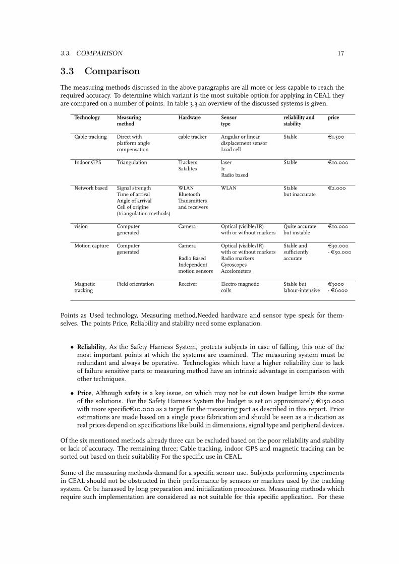
3.3 Comparison
The measuring methods discussed in the above paragraphs are all more or less capable to reach therequired accuracy. To determine which variant is the most suitable option for applying in CEAL theyare compared on a number of points. In table 3.3 an overview of the discussed systems is given.
Technology Measuring Hardware Sensor reliability and pricemethod type stability
Cable tracking Direct with cable tracker Angular or linear Stable €1.500platform angle displacement sensorcompensation Load cell
Indoor GPS Triangulation Trackers laser Stable €10.000Satalites Ir
Radio based
Network based Signal strength WLAN WLAN Stable €2.000Time of arrival Bluetooth but inaccurateAngle of arrival TransmittersCell of origine and receivers(triangulation methods)
vision Computer Camera Optical (visible/IR) Quite accurate €10.000generated with or without markers but instable
Motion capture Computer Camera Optical (visible/IR) Stable and €30.000generated with or without markers sufficiently - €50.000
Radio Based Radio markers accurateIndependent Gyroscopesmotion sensors Accelometers
Magnetic Field orientation Receiver Electro magnetic Stable but €3000tracking coils labour-intensive - €6000
Points as Used technology, Measuring method,Needed hardware and sensor type speak for them-selves. The points Price, Reliability and stability need some explanation.
• Reliability, As the Safety Harness System, protects subjects in case of falling, this one of themost important points at which the systems are examined. The measuring system must beredundant and always be operative. Technologies which have a higher reliability due to lackof failure sensitive parts or measuring method have an intrinsic advantage in comparison withother techniques.
• Price, Although safety is a key issue, on which may not be cut down budget limits the someof the solutions. For the Safety Harness System the budget is set on approximately €150.000with more specific€10.000 as a target for the measuring part as described in this report. Priceestimations are made based on a single piece fabrication and should be seen as a indication asreal prices depend on specifications like build in dimensions, signal type and peripheral devices.
Of the six mentioned methods already three can be excluded based on the poor reliability and stabilityor lack of accuracy. The remaining three; Cable tracking, indoor GPS and magnetic tracking can besorted out based on their suitability For the specific use in CEAL.
Some of the measuring methods demand for a specific sensor use. Subjects performing experimentsin CEAL should not be obstructed in their performance by sensors or markers used by the trackingsystem. Or be harassed by long preparation and initialization procedures. Measuring methods whichrequire such implementation are considered as not suitable for this specific application. For these

18 CHAPTER 3. SOLUTIONS
reasons the use of magnetic tracking is not considered the best method for this application.
With cablet racking and Indoor GPS both remaining as feasible solutions, the low cost price, easymaintainability and most important the simple design tip the scale in advantage of cablet racking.This is probably the most simple solution with the smallest chance for disturbances and hardwarefailure.

Chapter 4
Concept
In the previous chapters some possible solutions for the following of a person on the platform arediscussed. Out of this discussion the option of cable tracking as a measurement for the subjects dis-placement on the platform is chosen. In this chapter some points of interest, two measuring conceptsspecific elements of this solution are discussed.
4.1 Points of interest
As mentioned in chapter three there were some points of interest concerning this type of trackingsolution;
• The sensor which measures the platform orientation.
• Wobble and waves in the safety line.
Concerning the external sensor no further problems are expected. Industrial gyroscopes or even moresimple versions as used in model helicopters are available which can measure angles in three dimen-sions (Although only two would be sufficient!). They are also quite insensible for drift on the angularposition measurement. It could also be well possible to use superfluous rotational axis as a measure-ment for the drift of the gyroscope.This said, the angular position should always be set to zero before starting a new experiment. Andbefore implementing a gyroscope into the control loop of the safety harness system, the angular driftmust be examined.
When the safety line is used in the tracking system, wobble and waves could jeopardize the accuracyof the position measurement. Or in extreme cases could lead to instabilities in the safety harness’smotion system. For these reasons the absent of these effects are of the most importance.User tests performed with the North Safety decent controller gave no reason for expecting cable wob-ble. Due to the relative high cable stiffness, short span of the cable (typical less than two meters duringan simulation) and a preset tension, movement of the attached subjects does not cause wobble in thecable.
4.2 Joystick measuring
With Joystick measuring the safety line is followed by a joystick like pyramid, in which the cable isfed through, as can be seen in figure4.1. There are two axis in which two bodies are rotating. Theserotations are direct measures for the deflection of the safety line in X and Y direction. The rotationscan be measured by two rotational potentiometer resistance. These sensors can be, when placed in aWeedstone bridge, directly as a input signal for the motion system.
19

20 CHAPTER 4. CONCEPT
Figure 4.1: Schematic view of the joystick
Within the motion system a compensation for the platform angle should be made as the Joystick doesnot take take into account this angle.
4.3 Tension ring
Another possibility for measuring the deflection of the safety line is using a simple ring like infigure4.2. This ring is suspended in a statically determined way, so that the only possible movementsof the ring lie in the horizontal (XY)plane. The springs will give the ring a resistance against displace-ment. By choosing a sufficient high spring stiffness the system becomes more robust, and thereforeless sensible for small perturbations of the safety line. The stiffness of the springs is depending onthe thickness and stiffness of the safety line and the hight the ring is placed. The displacement of thering in the horizontal plane can be measured using load cells. Doing this, the output signal of the loadcells is a direct measurement for the deflection of the safety cable.[8]
Figure 4.2: Schematic view of tension ring
Even as in the previous case of the joystick measurement system a compensation must be made forthe platform angle. As the tension ring can only sense displacements in the horizontal plane paralleltot the platform floor.

4.4. COMPARISON 21
4.4 Comparison
When one wants to choose the best solution out of before given concepts a number of points should betaken into account. Although the second concept of the tension ring looks mechanically more simplethan the first one, there are two things that make it a more complicated solution.The load cells that are used would be more expensive than the rotational potentiometer used in thejoystick concept. Also the rotational potentiometer can be directly read out (with the help of a cheapWeedstone bridge) in contrast to the load cells which require more sophisticated electronics. An op-tion would be to replace the load cells with a linear resistance. But the sensitivity of such a linearresistance for wear and dust would make it not suitable for use in CEAL.
The other point is that the Joystick is constructively a more simple solution. All the mechanical mov-ing parts are rotating, which can easily be supported by rotational bearings. And the joystick itself canbe made out of low grade steel which is welded into the desired shape. This in contrast to the tensionring in which more high grade steel or even leaf springs have to be used.
The comments mentioned above and the expectation that both concept will work with the same accu-racy leads to the conclusion that the joystick measuring method is the most suitable solution for theproblem of person tracking on the platform.

22 CHAPTER 4. CONCEPT

Chapter 5
Conclusions and Recommendations
During this internship several parts of the safety harness system are studied. This resulted in in alist with a number of global and more specific requirements for the total system or for the safetyharness. Out of these requirements seven possible solutions were presented, which could all track aperson walking on the simulation platform. The chosen solution, cable tracking using a joystick likemeasurement device gives the desired accuracy and stability which is required for the use in the CEALproject. It is the most suitable solution based on;
• Simple construction
• Simple and reliable sensors
• Insensible for environmental conditions
• Easy maintainability
• Easy in daily use
• Total cost estimation well within the budget
Summarizing it can be said that the chosen solution is the most suitable because it is based on simple,cheap and proven technology.
This report is mend as a guidance document for The CEAL project and its subcontractors. It willtherefore not be complete but should be seen as a guidance for further implementation of the safetyharness system. In the future specific components and calculations have to be performed beforeimplementing the chosen solution into the CEAL simulation platform.
23

24 CHAPTER 5. CONCLUSIONS AND RECOMMENDATIONS

Bibliography
[1] Dr. S.K. Advani. Dual Subject Safety Harness Suspension System requirements. Number IDT-R-05-04Version 01. International Development of Technology, 2005.
[2] Jr. Moe Z. Win Damien B. Jourdan, John J. Deyst and Nicholas Roy. Monte Carlo Localization inDense Multipath Environments Using UWB Rangingy. Massachusetts Institute of Technology, 2005.
[3] M. Potter Dr. S.K. Advani. Request for information for the safety harness fall arrest system. NumberIDT-R-06-12 Version 1.1. International Development of Technology, 2006.
[4] M. Potter Dr. S.K. Advani. Safety Harness System Requirements. Number IDT-R-05-10 Version 1.9.International Development of Technology, 2006.
[5] Seong-Ho Kan and D. Tesar. Indoor GPS Metrology system with 3D probe for precision applications.The University of Texas, 2005.
[6] M. Potter. Design of a safety harness system for a dynamic walking simulator. Number DCT 2006.115.Technische Universiteit Eindhoven, 2006.
[7] M. Kofahl R. Bill, C. Cap and T. Mundt. Indoor and outdoor positioning in mobile envirionments.Number Vol. 10, No.2 ISSN 1082-4006. Geographic Information Sciences, 2005.
[8] P.C.J.N. Rosielle and E.A.G. Reker. “Constructieprincipes 1, bedoeld voor het nauwkeurig bewegen enpositioneren”. Technische Universiteit Eindhoven, 2000.
25

26 BIBLIOGRAPHY