traces of catastrophe - book
TRANSCRIPT
8/8/2019 Traces of Catastrophe - Book
http://slidepdf.com/reader/full/traces-of-catastrophe-book 1/130
8/8/2019 Traces of Catastrophe - Book
http://slidepdf.com/reader/full/traces-of-catastrophe-book 2/130
i
Traces of CatastropheA Handbook of Shock-Metamorphic Effects in
Terrestrial Meteorite Impact Structures
Bevan M. French
Research CollaboratorDepartment of Mineral Sciences, MRC-119
Smithsonian Institution Washington DC 20560
LPI Contribution No. 954
8/8/2019 Traces of Catastrophe - Book
http://slidepdf.com/reader/full/traces-of-catastrophe-book 3/130
ii
Copyright © 1998 by LUNAR AND PLANETARY INSTITUTE
The Institute is operated by the Universities Space Research Association under Contract No. NASW-4574 with the National Aeronautics and Space Administration.
Material in this volume may be copied without restraint for library, abstract service, education, or personalresearch purposes; however, republication of any portion thereof requires the written permission of the Insti-tute as well as the appropriate acknowledgment of this publication.
Figures 3.1, 3.2, and 3.5 used by permission of the publisher, Oxford University Press, Inc. Figures 3.13, 4.16,4.28, 4.32, and 4.33 used by permission of the publisher, Springer-Verlag. Figure 4.25 used by permission of the publisher, Yale University. Figure 5.1 used by permission of the publisher, Geological Society of America.See individual captions for reference citations.
This volume may be cited as
French B. M. (1998) Traces of Catastrophe: A Handbook of Shock-Metamorphic Effects in Terrestrial Meteorite Impact Structures. LPI Contribution No. 954, Lunar and Planetary Institute, Houston. 120 pp.
This volume is distributed by
ORDER DEPARTMENTLunar and Planetary Institute
3600 Bay Area BoulevardHouston TX 77058-1113, USA
Phone: 281-486-2172Fax: 281-486-2186
E-mail: [email protected]
Mail order requestors will be invoiced for the cost of shipping and handling.
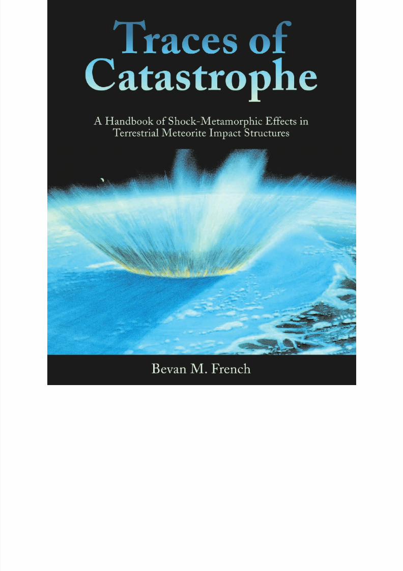
Cover Art. “One Minute After the End of the Cretaceous.” This artist’s view shows the ancestral Gulf of Mexico near the present Yucatán peninsula as it was 65 m.y. ago, just after the impact of an asteroid or comet about 10 km in diameter began to form the hugeChixculub (Mexico) impact structure. In only a minute after the impact, a transient crater about 100 km across has been excavated,cutting through the surface ocean water, the underlying carbonate sediments, and the deep-seated crystalline crustal rocks. The edge of the growing transient crater is marked by a curtain of material that is being ejected into the atmosphere. Earth’s Moon appears as a smalldot above and to the left of the ejecta curtain. Painting by William K. Hartmann; used by permission of the artist.

8/8/2019 Traces of Catastrophe - Book
http://slidepdf.com/reader/full/traces-of-catastrophe-book 4/130
iii
Dedicated to
Ralph B. Baldwin
Robert S. Dietz
Eugene M. Shoemaker
Who were so far ahead
Of all the rest of us.

8/8/2019 Traces of Catastrophe - Book
http://slidepdf.com/reader/full/traces-of-catastrophe-book 5/130
iv
8/8/2019 Traces of Catastrophe - Book
http://slidepdf.com/reader/full/traces-of-catastrophe-book 6/130
v
Contents
Chapter 1: LANDSCAPES WITH CRATERS: METEORITE IMPACTS,
EARTH, AND THE SOLAR SYSTEM ........................................................................................... 1
1.1. The New Geology: Meteorite Impacts on the Earth................................................................................................ 1
1.2. The Planetary Perspective......................................................................................................................................... 4
1.3. A Peculiar Process: Why Impacts are Different ........................................................................................................ 6
1.3.1. Rarity ....................................................................................................................................................... 7
1.3.2. Immense Energy ...................................................................................................................................... 7
1.3.3. Instant Effects .......................................................................................................................................... 7
1.3.4. Concentrated Energy Release ................................................................................................................... 8
1.3.5. Extreme Physical Conditions ................................................................................................................... 9
1.3.6. Unique Deformation Effects .................................................................................................................. 10
Chapter 2: TARGET EARTH: PRESENT, PAST, AND FUTURE ................................................................. 11
2.1. Comets and Asteroids: The Killer Neighbors? ....................................................................................................... 11
2.1.1. Asteroids ................................................................................................................................................ 112.1.2. Comets ................................................................................................................................................... 11
2.1.3. Close Encounters .................................................................................................................................... 12
2.2. In Our Time: Small Catastrophes.......................................................................................................................... 12
2.3. The Problems of Prediction: How Big, How Often? .............................................................................................. 12
2.3.1. Ingredients of Catastrophe ...................................................................................................................... 12
2.3.2. Uncertain Estimates................................................................................................................................13
2.3.3. An Uncertain Future? ............................................................................................................................. 16
Chapter 3: FORMATION OF IMPACT CRATERS ........................................................................................17
3.1. Shock Waves and Crater Formation ....................................................................................................................... 17
3.1.1. Contact/Compression Stage ................................................................................................................... 183.1.2. Excavation Stage: The Transient Crater ................................................................................................. 20
3.1.3. Modification Stage ................................................................................................................................. 23
3.2. Simple and Complex Impact Structures .................................................................................................................. 23
3.2.1. Simple Craters ........................................................................................................................................ 23
3.2.2. Complex Craters ..................................................................................................................................... 24
3.2.3. Multiring Basins ..................................................................................................................................... 27
3.3. Subsequent Development of Impact Structures ...................................................................................................... 28
Chapter 4: SHOCK-METAMORPHIC EFFECTS IN ROCKS AND MINERALS .......................................31
4.1. Formation Conditions and General Characteristics ................................................................................................. 31
4.2. Stages of Shock Metamorphism ............................................................................................................................. 36
4.3. Megascopic Shock-Deformation Features: Shatter Cones ...................................................................................... 36
4.4 High-Pressure Mineral Polymorphs ........................................................................................................................ 40
4.5. Planar Microstructures in Quartz ...........................................................................................................................42
4.5.1. Planar Fractures ...................................................................................................................................... 42
4.5.2. Planar Deformation Features (PDFs) ...................................................................................................... 42
4.5.3. PDF Orientations ................................................................................................................................... 49
4.5.4. PDFs in Sedimentary Rocks ................................................................................................................... 52
4.6. Planar Microstructures in Feldspar and Other Minerals .......................................................................................... 53
4.7. Shock Isotropization and Diaplectic Glasses ...........................................................................................................55
4.8. Selective Mineral Melting ...................................................................................................................................... 57
8/8/2019 Traces of Catastrophe - Book
http://slidepdf.com/reader/full/traces-of-catastrophe-book 7/130
vi
Chapter 5: SHOCK-METAMORPHOSED ROCKS (IMPACTITES) IN
IMPACT STRUCTURES ................................................................................................................. 61
5.1. Rock Types in the Final Impact Structure ...............................................................................................................61
5.2. Classification of Impactites..................................................................................................................................... 62
5.3. Subcrater Rocks ..................................................................................................................................................... 62
5.3.1. Formation Conditions............................................................................................................................. 62
5.3.2. In-Place Shock-Metamorphosed Rocks .................................................................................................. 63
5.3.3. Lithic Breccias (Parautochthonous) ......................................................................................................... 645.3.4. Cross-Cutting (Allogenic) Breccias ......................................................................................................... 64
5.3.5. Pseudotachylite ....................................................................................................................................... 65
5.4. Crater Interior: Crater-Fill Deposits (Breccias and Melt Rocks) ........................................................................... 69
5.4.1. Formation Conditions............................................................................................................................. 69
5.4.2. Lithic Breccias (Allogenic) ...................................................................................................................... 71
5.4.3. Melt-Fragment Breccias (Allogenic) (Suevites) .......................................................................................71
5.4.4. Melt-Matrix Breccias (Impact-Melt Breccias) ......................................................................................... 74
5.5. Crater Rim Zone and Proximal Ejecta Deposits ..................................................................................................... 74
5.6. Distal Ejecta ........................................................................................................................................................... 78
Chapter 6: IMPACT MELTS .............................................................................................................................79
6.1. Formation Conditions ............................................................................................................................................ 79
6.2. Impact Melt Volumes and Crater Size .................................................................................................................... 81
6.3. Impact Melt Varieties in the Near-Crater Environment.......................................................................................... 82
6.3.1. Small Glassy Bodies ................................................................................................................................ 82
6.3.2. Impact Melt Breccias .............................................................................................................................. 82
6.3.3. Large Crystalline Bodies (Dikes and Sills) ...............................................................................................86
6.4. Impact Melt in Distal Ejecta .................................................................................................................................. 87
6.4.1. Spherules ................................................................................................................................................ 88
6.4.2. Tektites and Microtektites ....................................................................................................................... 89
6.4.3. Miscellaneous Impact Glasses ................................................................................................................. 90
6.5. Recognition of Impact Melt Rocks......................................................................................................................... 90
Chapter 7: HOW TO FIND IMPACT STRUCTURES....................................................................................97
7.1. Reasons for the Search ........................................................................................................................................... 97
7.2. Detection of Candidate Impact Sites ...................................................................................................................... 97
7.2.1. Geological Features ................................................................................................................................. 98
7.2.2. Geophysical Features .............................................................................................................................. 98
7.3. Verification of Impact Structures ............................................................................................................................ 99
Chapter 8: WHAT NEXT? CURRENT PROBLEMS AND
FUTURE INVESTIGATIONS ...................................................................................................... 101
8.1. Identification of New Impact Structures ............................................................................................................... 101
8.2. Impact Events and Extinctions ............................................................................................................................. 101
8.3. Distal Impact Ejecta ............................................................................................................................................. 102
8.4. Carbon Chemistry in the Impact Environment .................................................................................................... 102
8.5. Postimpact Processes and Effects .......................................................................................................................... 103
8.6. Petrogenesis of Igneous Rocks: Impact Melts ...................................................................................................... 103
8.7. Impacts and the Early Earth ................................................................................................................................. 104
Appendix ....................................................................................................................................................................... 107
References ..................................................................................................................................................................... 111
8/8/2019 Traces of Catastrophe - Book
http://slidepdf.com/reader/full/traces-of-catastrophe-book 8/130
vii
Preface
Meteorite impacts are getting plenty of respect these days. The public regards them asthe established destroyer of dinosaurs and as the possible destroyer of civilization. The largeplanetary science community sees impacts as the process that helped form the solar system
and is still modifying planets more than 4 b.y. later. Increasing numbers of geoscientists arecoming to appreciate the importance of meteorite impact events and the extent of theirinfluence on the geological and biological history of Earth.
However, despite the growing importance of meteorite impact phenomena in terrestrialgeology, the topic is still not widely addressed in general geoscience textbooks and references.(Some exceptions are Dence and Robertson, 1989; Philpotts, 1990, Chapter 14-9; Melosh,1992; and Hibbard, 1995, Chapter 24.) The geoscientist seeking instruction and informationabout impacts therefore faces a body of literature that, although large, is both specialized andscattered: isolated review articles (e.g., Grieve, 1991; Grieve and Pesonen, 1992; Grieve and Pilkington, 1996); older volumes on shock waves and cratering mechanics (Roddy et al., 1977; Melosh, 1989) and shock metamorphism (French and Short, 1968); collections of papers inspecial issues of various journals (Hörz, 1971; Nicolaysen and Reimold, 1990; Pesonen and Henkel, 1992; Glikson, 1996b); and several good histories and memoirs (Hoyt, 1987; Mark,
1987; Alvarez, 1997). The linking of meteorite impacts to at least one extinction event( Alvarez et al., 1980) has brought impact processes into the geological mainstream, and thistrend is reflected by the appearance of several Special Papers of the Geological Society of America, each one a collection of technical papers involving extinctions (Silver and Schultz,1982; Sharpton and Ward, 1990; Ryder et al., 1996) and planetary cratering (Dressler et al.,1994; Koeberl and Anderson, 1996a). More recently, several books have given serious con-sideration to large impact events in the present (Spencer and Mitton, 1995) and to thehazards associated with possible impact events in the future (Chapman and Morrison, 1989;Gehrels, 1994).
It is therefore surprising and unfortunate that no complete and systematic introductory textbook for geoscientists has yet appeared. With this book, I have attempted to fill this gapand provide for geoscientists a detailed introduction and overview of impact processes, craterformation, and shock metamorphism. The book is not intended for a general reader, nor is it
aimed primarily at specialists actually working in impact geology. It is intended for geoscien-tists of all kinds: students who want to learn about the importance of meteorite impact;professors who want to add impact information to their geoscience courses; and professionalgeologists who may unexpectedly encounter an impact structure in the next field area or inthe next drill core.
The book therefore emphasizes terrestrial impact structures, field geology, and particularly the recognition and petrographic study of shock-metamorphic effects in terrestrial rocks. Asa result, I have deliberately left out or summarized only briefly many important and excitingaspects of impact geology: shock-wave physics, cratering mechanics, cratering on otherplanets, ejecta formation and deposits, extinction mechanisms, geochemical and geophysicalstudies of impact structures, and tektites. However, I have included literature references toget the interested reader started on further exploration in these fields.
Although this book could be used as a textbook, albeit a very focused one, I view it as acombination of sourcebook, laboratory manual, and reference for working geologists. Thechapters are designed to be read independently, depending on the background and needs of the reader. Nonspecialists or readers interested in general information can explore the early chapters (Chapters 1 and 2). Geoscientists with backgrounds in structural geology, mineral-ogy, and petrology may prefer to go directly to the detailed information on crateringmechanics (Chapter 3), shock-metamorphic features (Chapter 4), impactites (Chapter 5),impact melts (Chapter 6), or the detection and identification of new impact structures(Chapter 7). With this presentation, some introductory material is repeated in differentchapters, but I hope the arrangement will be useful for a wide range of readers interestedin various aspects of impact.

8/8/2019 Traces of Catastrophe - Book
http://slidepdf.com/reader/full/traces-of-catastrophe-book 9/130
viii
In any field of science, the fine details of terminology are complicated and often controversial.Impact geology is no exception. I have tried to keep things simple, even at the loss of some precision.For example, I use meteorite as a general term for any extraterrestrial object, regardless of size, composi-tion, or source, that is large enough to strike Earth’s surface and to make a crater. More specific terms(asteroid, comet, projectile, etc.) are reserved for more specific contexts. Similarly, I use impact crater and impact structure more or less interchangeably, despite the actual differences that exist betweenthem Finally, I have kept the classification of impactites (breccias, impact melts, etc.) as simple aspossible. I hope this approach will help communicate information to all kinds of readers and will also
prepare specialists to explore the details as needed.I owe a great deal to many colleagues, who responded both promptly and generously to my many
requests for samples, photographs, literature references, and other material needed for this book. I amespecially grateful to those who supplied photographs, particularly Richard Grieve, Glenn Izett, andDieter Stöffler. The reader will also note my extensive reliance on Jay Melosh’s textbook ( Melosh, 1989),
which, after nearly a decade, still remains an essential sourcebook on the theoretical aspects of crater-ing mechanics and shock metamorphism. I am equally indebted to other colleagues who reviewed the
various versions of the changing manuscript, and whose criticisms and comments produced majorimprovements: Burkhard Dressler, Richard Grieve, Fred Hörz, Christian Koeberl, Bruce Marsh,Anthony Philpotts, Virgil Sharpton, Richard Wunderman, and Mary-Hill French. Any errors,misstatements, and other flaws that managed to survive are entirely my own.
I am also grateful to the staff at the Lunar and Planetary Institute, especially Mary Cloud, for theircontinued interest in this undertaking, for their patience while it was slowly taking shape, and for theirusual speed and editorial excellence in the final production. I thank Debra Rueb and Mary Ann Hagerfor providing graphics and other resources from the LPI library, and Stephen L. Hokanson andReneé Dotson for their editorial and digital publishing expertise. William K. Hartmann generously provided one of his striking paintings for use on the cover. Finally, I am grateful for the continuedsupport of the Smithsonian Institution, which allowed me to continue working on this book as aResearch Collaborator in the Department of Mineral Sciences since 1994.
The field of impact geology continues to expand in scope and importance, as the statistically mindedreader can see from the bibliography; the number and variety of articles on the subject published in
just the last five years is impressive. Even though approximately 150 terrestrial impact structures areknown, several hundred remain to be discovered and studied, perhaps as genuine exercises for students.Beyond the identification of new impact structures, we are just beginning to explore the role of impactsin major geological processes: the actual mechanisms by which extinctions are produced, the recogni-
tion of distal ejecta deposits in the geological record, and the role of large impacts in shaping thePrecambrian Earth. I hope this book will help in the explorations to come.
Bevan M. FrenchChevy Chase, Maryland September 1998

8/8/2019 Traces of Catastrophe - Book
http://slidepdf.com/reader/full/traces-of-catastrophe-book 10/130
ix
Metric and standard international (SI) units are used throughout. Length units are meters (m), millimeters (mm), centi-meters (cm), decimeters (dm), kilometers (km), and micrometers (µm). In planetary discussions, the astronomical unit (AU)is also used; 1AU= 150× 106km. Mass units are grams (g), milligrams (mg), kilograms (kg), and micrograms (µg). Larger
masses are given in tons (T, 1T = 106
kg), kilotons (kT, or 103
T), and megatons (MT, or 106
T).
Ages of stratigraphic units or times of geologic events are given in kilo-annum (ka, 103 years before present), Mega-annum (Ma, 106 years before present), and Giga-annum (Ga, 109 years before present). (“Present” in this sense refers to 1950A.D.) Length units of time used are billion years (b.y.), million years (m.y.), years (yr), minutes (min), and seconds (s).
Energies are given in joules ( J). Pressures are in gigapascals (GPa); 1GPa = 10kilobars (kbar); 100 GPa = 1 Megabar(Mbar). Other miscellaneous abbreviations used are diameter (D) and Cretaceous-Tertiary (K/T).
Technical terms are highlighted where they are first defined in the text. Terms directly related to cratering and shock metamorphism are shown in boldface; other technical terms are shown in italics.
A Note on Style

8/8/2019 Traces of Catastrophe - Book
http://slidepdf.com/reader/full/traces-of-catastrophe-book 11/130
x
8/8/2019 Traces of Catastrophe - Book
http://slidepdf.com/reader/full/traces-of-catastrophe-book 12/130
Landscapes with Craters 1
1.1. THE NEW GEOLOGY: METEORITEIMPACTS ON THE EARTH
During the last 30 years, there has been an immense andunexpected revolution in our picture of Earth and its placein the solar system. What was once a minor astronomicalprocess has become an important part of the geological main-stream. Impacts of extraterrestrial objects on the Earth, onceregarded as an exotic but geologically insignificant process,have now been recognized as a major factor in the geologicaland biological history of the Earth. Scientists and the public
have both come to realize that terrestrial impact structuresare more abundant, larger, older, more geologically complex,more economically important, and even more biologically significant than anyone would have predicted a few decadesago. Impact events have generated large crustal disturbances,produced huge volumes of igneous rocks, formed majorore deposits, and participated in at least one major biologi-cal extinction.
Before the 1960s, collisions of extraterrestrial objects withthe Earth were not considered significant. Geologists didagree (and had agreed since the early 1800s) that pieces of extraterrestrial material did occasionally penetrate the atmos-phere and strike Earth’s surface, but the only visible results
of such collisions were a collection of meteorites to study and display in museums, together with a few small andgeologically short-lived meteorite craters, usually located inout-of-the-way desert areas (Fig. 1.1). Almost no one be-lieved that extraterrestrial objects could produce major geo-logical effects or that such projectiles could be any more thana local hazard.
This simple view has changed drastically, and the changereflects two major factors: (1) explorations of the solar sys-tem by humans and robotic spacecraft, which have estab-lished the importance of impact cratering in shaping all the
planets, including Earth (Taylor, 1982, Chapter 3; 1992,Chapter 4); and (2) the ability to definitely identify terres-trial impact structures, especially large or ancient ones,by the presence of unique petrological and geochemicalcriteria, particularly the distinctive shock-metamorphiceffects produced in rocks and minerals by the intense shock
waves generated in impact events (French, 1968a; French and Short, 1968).
In the last few decades, geologists have gradually realizedthat collisions of extraterrestrial objects with Earth — andespecially the rare but catastrophic impacts of kilometer-sized
asteroids and comets — have significantly shaped Earth’ssurface, disturbed its crust, and altered its geological history (French, 1968a, 1990b; Shoemaker, 1977;Grieve, 1987, 1990,1991; Nicolaysen and Reimold, 1990; Pesonen and Henkel,1992; Dressler et al., 1994).
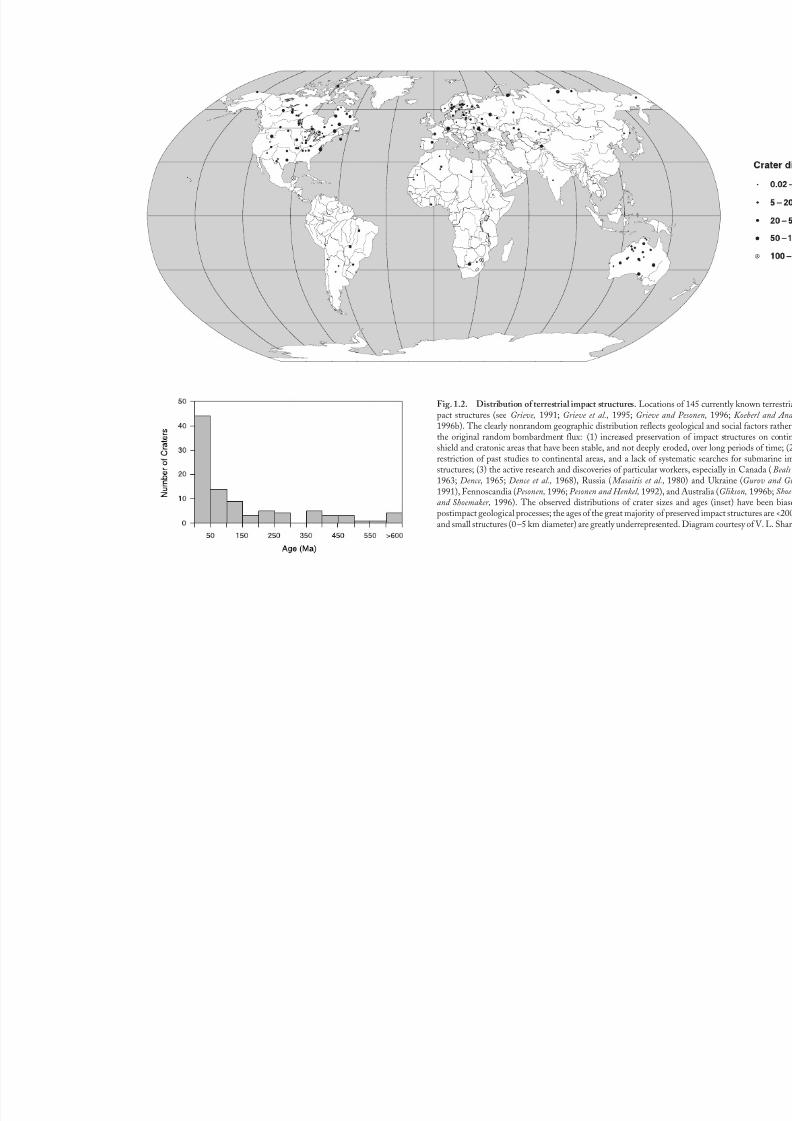
The record of impacts on Earth is still being deciphered.Approximately 150 individual geological structures havealready been identified as the preserved results of such im-pacts (Grieve, 1991, 1994; Grieve et al., 1995; Grieve and Pesonen, 1992, 1996), and it is estimated that several hun-dred more impact structures remain to be identified (Trefil and Raup, 1990; Grieve, 1991). The known impact struc-tures (Fig. 1.2) range from small circular bowls only a few
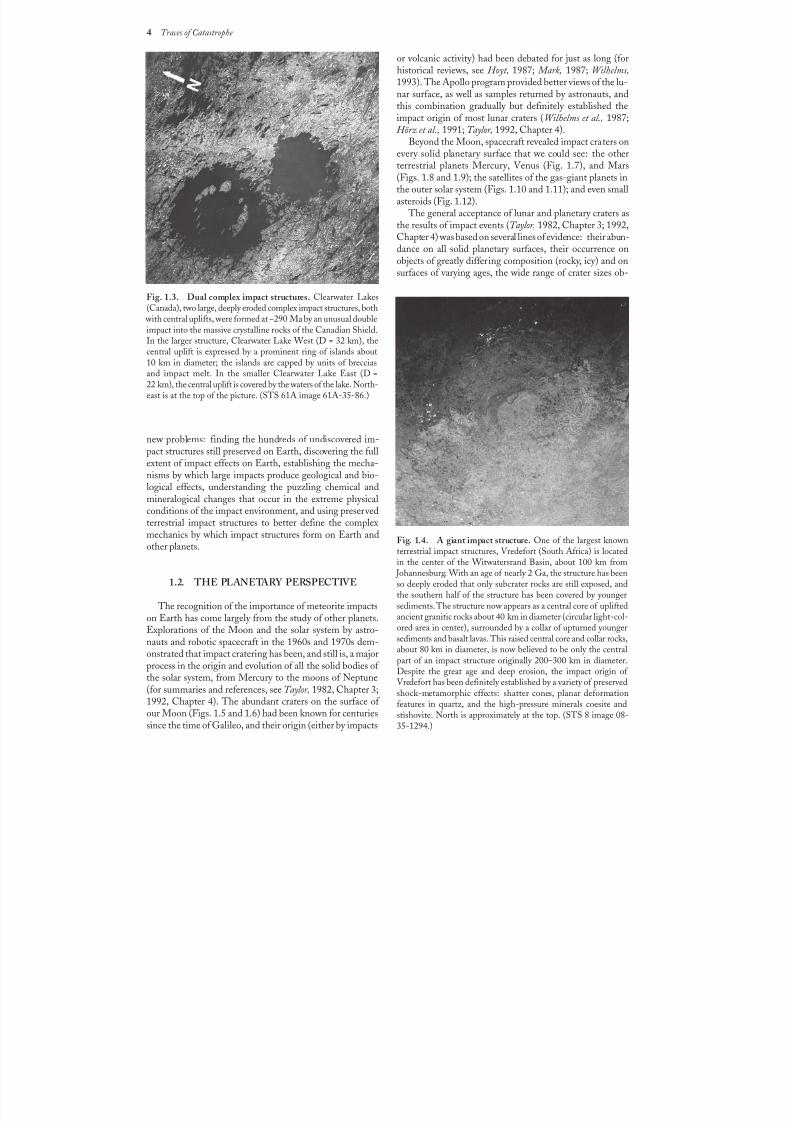
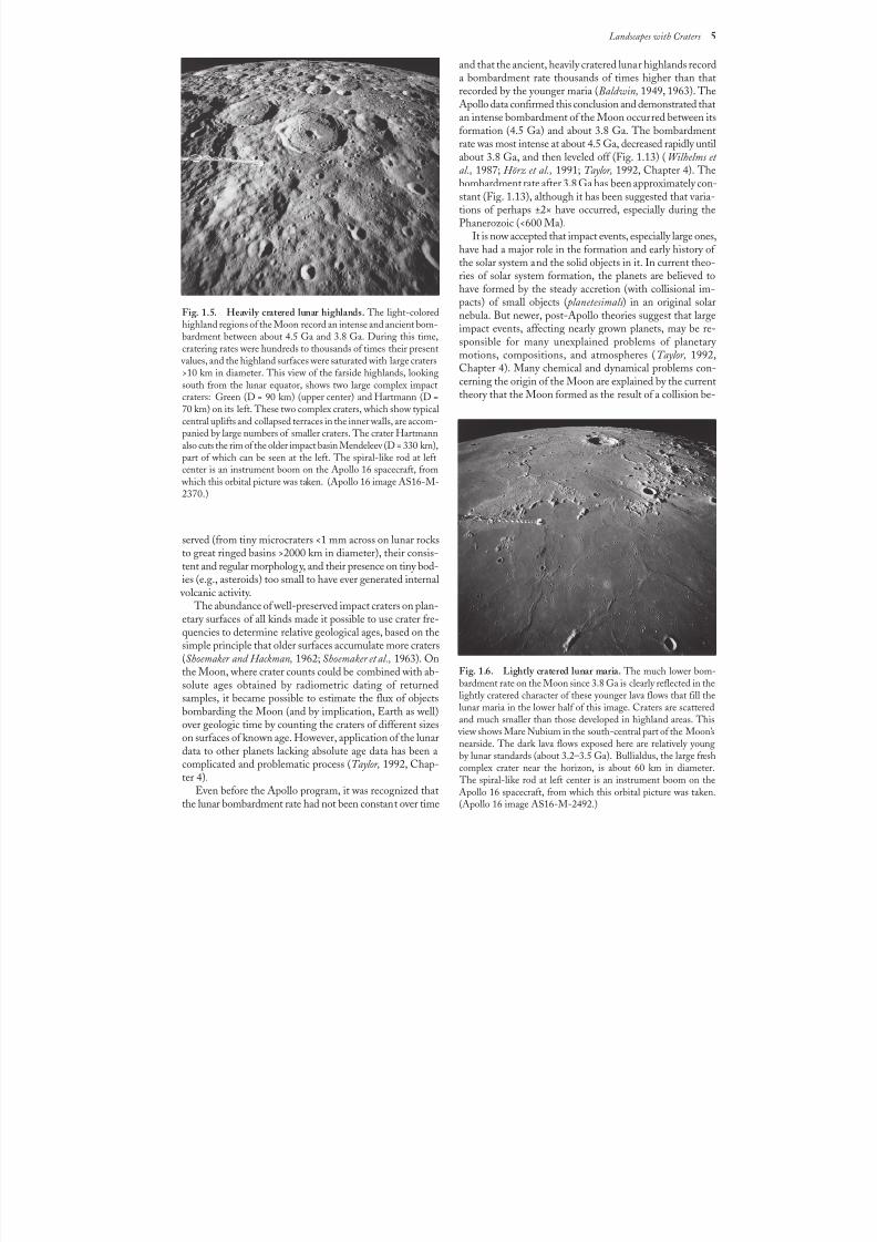
kilometers or less in diameter (Fig. 1.1) to large complexstructures more than 200 km in diameter and as old as2 Ga (Figs.1.3 and 1.4). Formation of the larger features,such as the Sudbury (Canada) and Vredefort (South Africa)structures, involved widespread disturbances in Earth’s crustand major perturbations in the geologic history of the re-gions where they were formed.
In addition to the geological disturbances involved, im-pact events have produced several geological structures
with actual economic value; a production value of about$5 billion per year has been estimated for North American
Landscapes with Craters: Meteorite Impacts,Earth, and the Solar System
1
8/8/2019 Traces of Catastrophe - Book
http://slidepdf.com/reader/full/traces-of-catastrophe-book 13/130
2 Traces of Catastrophe
impact structures alone (Grieve and Masaitis, 1994). The eco-nomic products of impact structures include such diverseitems as local building stone, diamonds, and uranium.
Hydrocarbons (petroleum and gas) are an especially impor-tant product from impact structures (Donofrio, 1997; Johnsonand Campbell, 1997). Large impacts crush and shatter thetarget rocks extensively beneath and around the crater; in afew structures [e.g., Ames (Oklahoma); Red Wing Creek (North Dakota)], the resulting breccia zones have served astraps for oil and gas. Within and around other impact cra-ters, the other kinds of breccias produced by the impacthave provided building stone [Ries Crater (Germany);Rochechouart (France)] and industrial limestone [Kentland(Indiana)]. In some cases, the sediments that subsequently fill the crater depressions may contain deposits of such eco-nomic materials as oil shale [Boltysh (Ukraine)], diatomite
[Ragozinka (Russia)], gypsum [Lake St. Martin (Canada)],and lead-zinc ores [Crooked Creek (Missouri)].
The biggest impact-related bonanza (current productionabout $2 billion per year) is the Sudbury structure (Canada),
which contains one of the largest nickel-copper sulfide de-posits on Earth (Guy-Bray, 1972; E. G. Pye et al., 1984;Dressler et al., 1994; Lightfoot and Naldrett, 1994). The de-posit occurs at the base of a large igneous body (the Sudbury Igneous Complex), which is in turn emplaced in a large, com-plex, and highly deformed impact basin nearly 2 b.y. old.
Terrestrial life itself has not escaped this cosmic bom-bardment. During the last 20 years an impressive amount of evidence has accumulated to show that at least one large
impact event about 65 m.y. ago redirected biological evolu-tion on Earth by producing the major extinction that now marks the boundary between the Cretaceous and Tertiary periods, the point at which the dinosaurs died and mam-mals (our ancestors) became major players in the history of terrestrial life ( Alvarez et al., 1980; Silver and Schultz, 1982; McLaren and Goodfellow, 1990; Sharpton and Ward, 1990;Ryder et al., 1996; Alvarez, 1997). The giant crater producedby that collision has now been definitely identified, a struc-ture [Chicxulub (Mexico)] at least 180 km across, completely buried under the younger sediments of Mexico’s YucatánPeninsula (Hildebrand et al., 1991; Sharpton et al., 1992; Morgan et al., 1997). Active debates continue about how this
catastrophic event actually produced the extinction and whether similar impacts have caused the other major andminor extinctions recorded in the geologic record.
Although the recognition of impact events and their ef-fects on Earth has been marked by debate and controversy (e.g., Dietz, 1963; Bucher, 1963; French, 1968a, 1990b;Sharpton and Grieve, 1990; Nicolaysen and Reimold, 1990),there is no longer any need to demonstrate either the exist-ence or the importance of such impact events. The youngbut maturing science of impact geology is turning toward
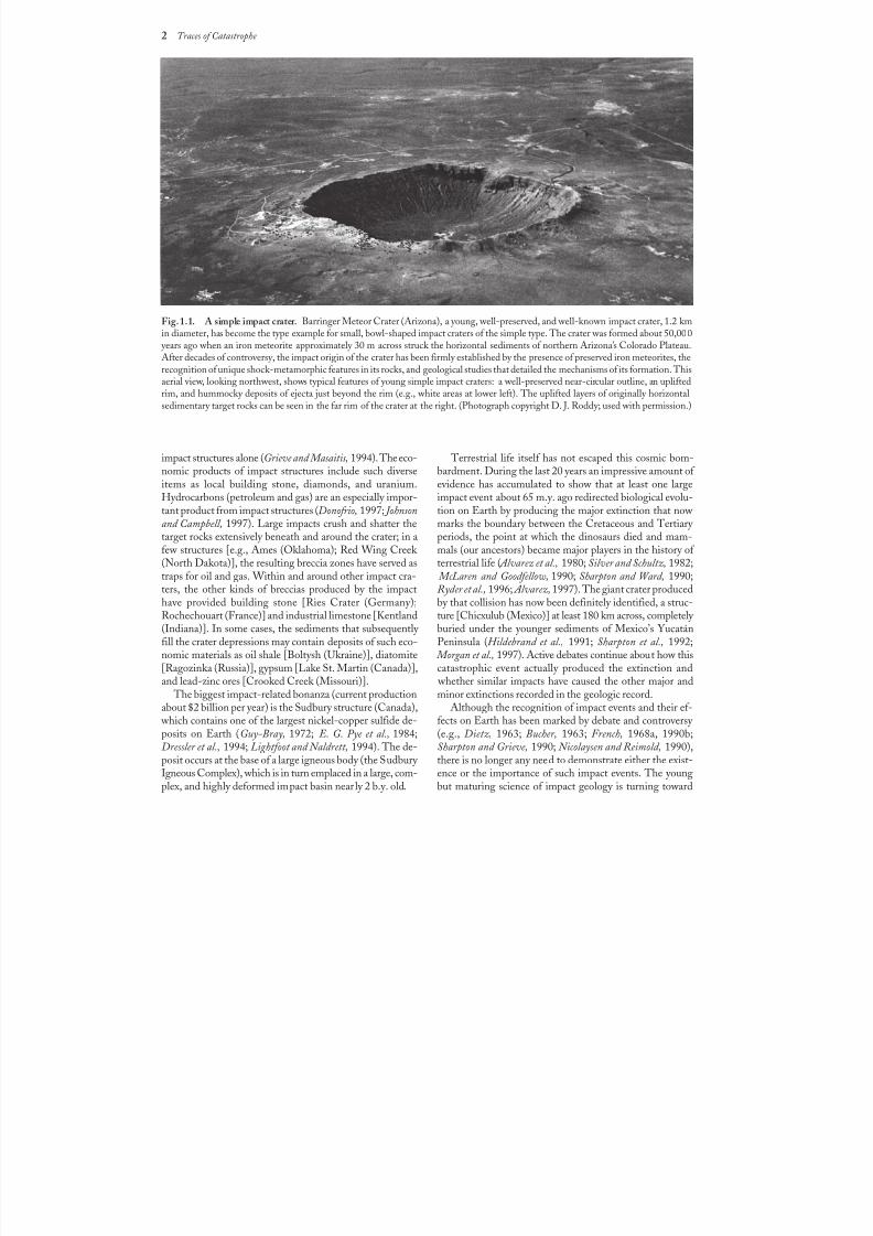
Fig. 1.1. A simple impact crater. Barringer Meteor Crater (Arizona), a young, well-preserved, and well-known impact crater, 1.2km
in diameter, has become the type example for small, bowl-shaped impact craters of the simple type. The crater was formed about 50,000 years ago when an iron meteorite approximately 30 m across struck the horizontal sediments of northern Arizona’s Colorado Plateau.After decades of controversy, the impact origin of the crater has been firmly established by the presence of preserved iron meteorites, therecognition of unique shock-metamorphic features in its rocks, and geological studies that detailed the mechanisms of its formation. Thisaerial view, looking northwest, shows typical features of young simple impact craters: a well-preserved near-circular outline, an upliftedrim, and hummocky deposits of ejecta just beyond the rim (e.g., white areas at lower left). The uplifted layers of originally horizontalsedimentary target rocks can be seen in the far rim of the crater at the right. (Photograph copyright D. J. Roddy; used with permission.)
8/8/2019 Traces of Catastrophe - Book
http://slidepdf.com/reader/full/traces-of-catastrophe-book 14/130
Fig. 1.2. Distribution of terrestrial impact structures. Locatipact structures (see Grieve, 1991; Grieve et al., 1995; Grieve 1996b). The clearly nonrandom geographic distribution reflectthe original random bombardment flux: (1) increased preservshield and cratonic areas that have been stable, and not deeply restriction of past studies to continental areas, and a lack of sstructures; (3) the active research and discoveries of particular w1963; Dence, 1965; Dence et al., 1968), Russia ( Masaitis et al.1991), Fennoscandia (Pesonen, 1996; Pesonen and Henkel, 1992)and Shoemaker, 1996). The observed distributions of crater sipostimpact geological processes; the ages of the great majority oand small structures (0–5 km diameter) are greatly underreprese
8/8/2019 Traces of Catastrophe - Book
http://slidepdf.com/reader/full/traces-of-catastrophe-book 15/130
4 Traces of Catastrophe
new problems: finding the hundreds of undiscovered im-
pact structures still preserved on Earth, discovering the fullextent of impact effects on Earth, establishing the mecha-nisms by which large impacts produce geological and bio-logical effects, understanding the puzzling chemical andmineralogical changes that occur in the extreme physicalconditions of the impact environment, and using preservedterrestrial impact structures to better define the complexmechanics by which impact structures form on Earth andother planets.
1.2. THE PLANETARY PERSPECTIVE
The recognition of the importance of meteorite impactson Earth has come largely from the study of other planets.Explorations of the Moon and the solar system by astro-nauts and robotic spacecraft in the 1960s and 1970s dem-onstrated that impact cratering has been, and still is, a majorprocess in the origin and evolution of all the solid bodies of the solar system, from Mercury to the moons of Neptune(for summaries and references, see Taylor, 1982, Chapter 3;1992, Chapter 4). The abundant craters on the surface of our Moon (Figs. 1.5 and 1.6) had been known for centuriessince the time of Galileo, and their origin (either by impacts
Fig. 1.4. A giant impact structure. One of the largest knownterrestrial impact structures, Vredefort (South Africa) is locatedin the center of the Witwatersrand Basin, about 100 km from
Johannesburg. With an age of nearly 2 Ga, the structure has beenso deeply eroded that only subcrater rocks are still exposed, andthe southern half of the structure has been covered by younger
sediments. The structure now appears as a central core of upliftedancient granitic rocks about 40 km in diameter (circular light-col-ored area in center), surrounded by a collar of upturned youngersediments and basalt lavas. This raised central core and collar rocks,about 80km in diameter, is now believed to be only the centralpart of an impact structure originally 200–300 km in diameter.Despite the great age and deep erosion, the impact origin of Vredefort has been definitely established by a variety of preservedshock-metamorphic effects: shatter cones, planar deformationfeatures in quartz, and the high-pressure minerals coesite andstishovite. North is approximately at the top. (STS 8 image 08-35-1294.)
Fig. 1.3. Dual complex impact structures. Clearwater Lakes(Canada), two large, deeply eroded complex impact structures, both
with central uplifts, were formed at ~290 Ma by an unusual doubleimpact into the massive crystalline rocks of the Canadian Shield.In the larger structure, Clearwater Lake West (D = 32km), thecentral uplift is expressed by a prominent ring of islands about10 km in diameter; the islands are capped by units of brecciasand impact melt. In the smaller Clearwater Lake East (D=22km), the central uplift is covered by the waters of the lake. North-east is at the top of the picture. (STS 61A image 61A-35-86.)
or volcanic activity) had been debated for just as long (forhistorical reviews, see Hoyt, 1987; Mark, 1987; Wilhelms,1993). The Apollo program provided better views of the lu-nar surface, as well as samples returned by astronauts, andthis combination gradually but definitely established theimpact origin of most lunar craters (Wilhelms et al., 1987;Hörz et al., 1991; Taylor, 1992, Chapter 4).
Beyond the Moon, spacecraft revealed impact craters on
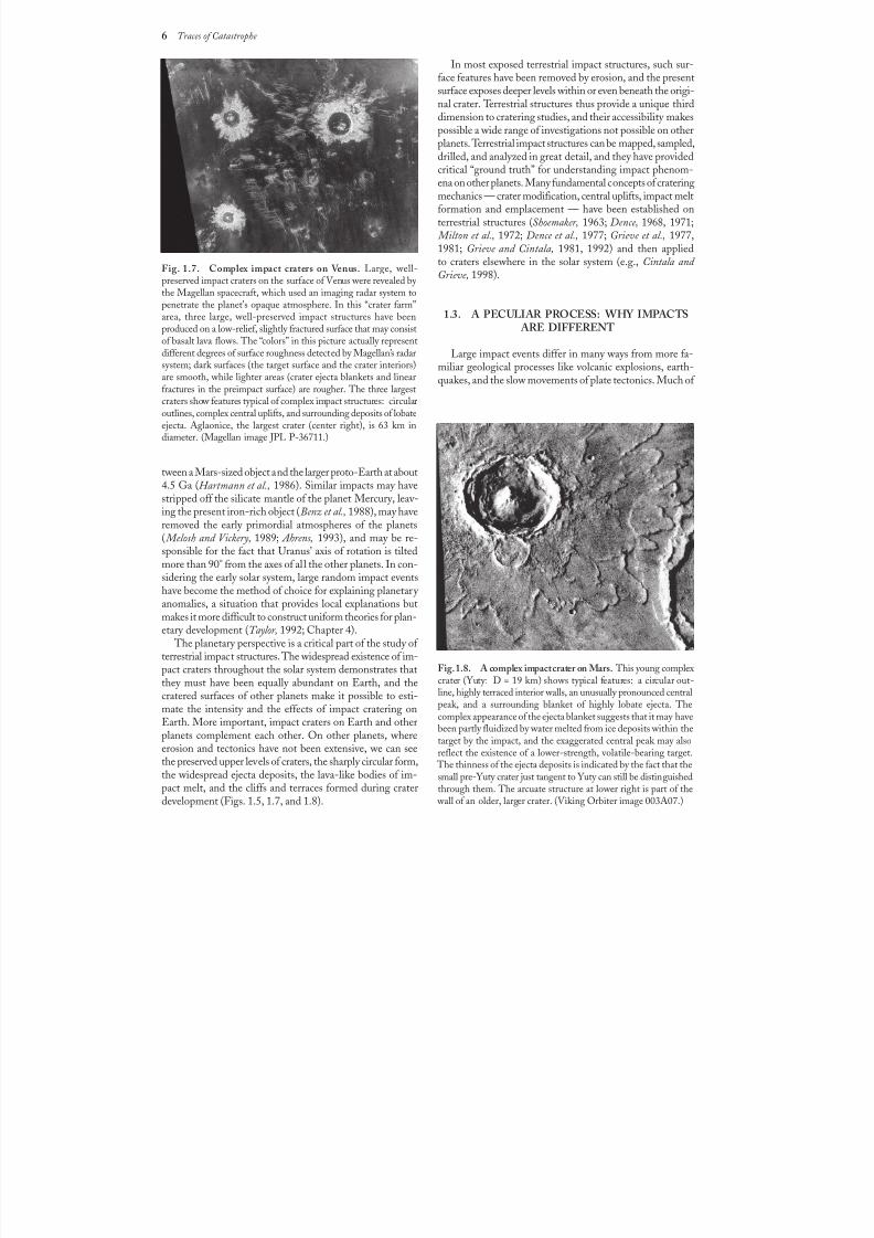
every solid planetary surface that we could see: the otherterrestrial planets Mercury, Venus (Fig. 1.7), and Mars(Figs. 1.8 and 1.9); the satellites of the gas-giant planets inthe outer solar system (Figs. 1.10 and 1.11); and even smallasteroids (Fig. 1.12).
The general acceptance of lunar and planetary craters asthe results of impact events (Taylor, 1982, Chapter 3; 1992,Chapter 4) was based on several lines of evidence: their abun-dance on all solid planetary surfaces, their occurrence onobjects of greatly differing composition (rocky, icy) and onsurfaces of varying ages, the wide range of crater sizes ob-
8/8/2019 Traces of Catastrophe - Book
http://slidepdf.com/reader/full/traces-of-catastrophe-book 16/130
Landscapes with Craters 5
Fig. 1.6. Lightly cratered lunar maria. The much lower bom-bardment rate on the Moon since 3.8 Ga is clearly reflected in thelightly cratered character of these younger lava flows that fill thelunar maria in the lower half of this image. Craters are scatteredand much smaller than those developed in highland areas. This
view shows Mare Nubium in the south-central part of the Moon’snearside. The dark lava flows exposed here are relatively youngby lunar standards (about 3.2–3.5 Ga). Bullialdus, the large freshcomplex crater near the horizon, is about 60 km in diameter.
The spiral-like rod at left center is an instrument boom on theApollo 16 spacecraft, from which this orbital picture was taken.(Apollo 16 image AS16-M-2492.)
Fig. 1.5. Heavily cratered lunar highlands. The light-coloredhighland regions of the Moon record an intense and ancient bom-
bardment between about 4.5 Ga and 3.8 Ga. During this time,cratering rates were hundreds to thousands of times their present
values, and the highland surfaces were saturated with large craters>10 km in diameter. This view of the farside highlands, lookingsouth from the lunar equator, shows two large complex impactcraters: Green (D = 90 km) (upper center) and Hartmann (D =70 km) on its left. These two complex craters, which show typicalcentral uplifts and collapsed terraces in the inner walls, are accom-panied by large numbers of smaller craters. The crater Hartmannalso cuts the rim of the older impact basin Mendeleev (D = 330km),part of which can be seen at the left. The spiral-like rod at leftcenter is an instrument boom on the Apollo 16 spacecraft, from
which this orbital picture was taken. (Apollo 16 image AS16-M-2370.)
served (from tiny microcraters <1 mm across on lunar rocksto great ringed basins >2000 km in diameter), their consis-tent and regular morphology, and their presence on tiny bod-ies (e.g., asteroids) too small to have ever generated internal
volcanic activity. The abundance of well-preserved impact craters on plan-
etary surfaces of all kinds made it possible to use crater fre-quencies to determine relative geological ages, based on thesimple principle that older surfaces accumulate more craters(Shoemaker and Hackman, 1962; Shoemaker et al., 1963). On
the Moon, where crater counts could be combined with ab-solute ages obtained by radiometric dating of returnedsamples, it became possible to estimate the flux of objectsbombarding the Moon (and by implication, Earth as well)over geologic time by counting the craters of different sizeson surfaces of known age. However, application of the lunardata to other planets lacking absolute age data has been acomplicated and problematic process (Taylor, 1992, Chap-ter 4).
Even before the Apollo program, it was recognized thatthe lunar bombardment rate had not been constant over time
and that the ancient, heavily cratered lunar highlands recorda bombardment rate thousands of times higher than thatrecorded by the younger maria (Baldwin, 1949, 1963). TheApollo data confirmed this conclusion and demonstrated thatan intense bombardment of the Moon occurred between itsformation (4.5 Ga) and about 3.8 Ga. The bombardmentrate was most intense at about 4.5 Ga, decreased rapidly untilabout 3.8 Ga, and then leveled off (Fig. 1.13) (Wilhelms et
al., 1987; Hörz et al., 1991; Taylor, 1992, Chapter 4). Thebombardment rate after 3.8 Ga has been approximately con-stant (Fig. 1.13), although it has been suggested that varia-tions of perhaps ±2× have occurred, especially during thePhanerozoic (<600 Ma).
It is now accepted that impact events, especially large ones,have had a major role in the formation and early history of the solar system and the solid objects in it. In current theo-ries of solar system formation, the planets are believed tohave formed by the steady accretion (with collisional im-pacts) of small objects ( planetesimals) in an original solarnebula. But newer, post-Apollo theories suggest that largeimpact events, affecting nearly grown planets, may be re-sponsible for many unexplained problems of planetary motions, compositions, and atmospheres (Taylor, 1992,Chapter 4). Many chemical and dynamical problems con-cerning the origin of the Moon are explained by the currenttheory that the Moon formed as the result of a collision be-
8/8/2019 Traces of Catastrophe - Book
http://slidepdf.com/reader/full/traces-of-catastrophe-book 17/130
6 Traces of Catastrophe
Fig. 1.7. Complex impact craters on Venus. Large, well-preserved impact craters on the surface of Venus were revealed by the Magellan spacecraft, which used an imaging radar system topenetrate the planet’s opaque atmosphere. In this “crater farm”area, three large, well-preserved impact structures have beenproduced on a low-relief, slightly fractured surface that may consistof basalt lava flows. The “colors” in this picture actually representdifferent degrees of surface roughness detected by Magellan’s radarsystem; dark surfaces (the target surface and the crater interiors)are smooth, while lighter areas (crater ejecta blankets and linearfractures in the preimpact surface) are rougher. The three largestcraters show features typical of complex impact structures: circularoutlines, complex central uplifts, and surrounding deposits of lobateejecta. Aglaonice, the largest crater (center right), is 63 km indiameter. (Magellan image JPL P-36711.)
Fig. 1.8. A complex impact crater on Mars. This young complexcrater (Yuty: D = 19 km) shows typical features: a circular out-line, highly terraced interior walls, an unusually pronounced centralpeak, and a surrounding blanket of highly lobate ejecta. Thecomplex appearance of the ejecta blanket suggests that it may havebeen partly fluidized by water melted from ice deposits within thetarget by the impact, and the exaggerated central peak may alsoreflect the existence of a lower-strength, volatile-bearing target.
The thinness of the ejecta deposits is indicated by the fact that thesmall pre-Yuty crater just tangent to Yuty can still be distinguishedthrough them. The arcuate structure at lower right is part of the
wall of an older, larger crater. (Viking Orbiter image 003A07.)
tween a Mars-sized object and the larger proto-Earth at about4.5 Ga (Hartmann et al., 1986). Similar impacts may have
stripped off the silicate mantle of the planet Mercury, leav-ing the present iron-rich object (Benz et al., 1988), may haveremoved the early primordial atmospheres of the planets( Melosh and Vickery, 1989; Ahrens, 1993), and may be re-sponsible for the fact that Uranus’ axis of rotation is tiltedmore than 90° from the axes of all the other planets. In con-sidering the early solar system, large random impact eventshave become the method of choice for explaining planetary anomalies, a situation that provides local explanations butmakes it more difficult to construct uniform theories for plan-etary development (Taylor, 1992; Chapter 4).
The planetary perspective is a critical part of the study of terrestrial impact structures. The widespread existence of im-
pact craters throughout the solar system demonstrates thatthey must have been equally abundant on Earth, and thecratered surfaces of other planets make it possible to esti-mate the intensity and the effects of impact cratering onEarth. More important, impact craters on Earth and otherplanets complement each other. On other planets, whereerosion and tectonics have not been extensive, we can seethe preserved upper levels of craters, the sharply circular form,the widespread ejecta deposits, the lava-like bodies of im-pact melt, and the cliffs and terraces formed during craterdevelopment (Figs. 1.5, 1.7, and 1.8).
In most exposed terrestrial impact structures, such sur-face features have been removed by erosion, and the presentsurface exposes deeper levels within or even beneath the origi-nal crater. Terrestrial structures thus provide a unique thirddimension to cratering studies, and their accessibility makespossible a wide range of investigations not possible on otherplanets. Terrestrial impact structures can be mapped, sampled,drilled, and analyzed in great detail, and they have provided
critical “ground truth” for understanding impact phenom-ena on other planets. Many fundamental concepts of crateringmechanics — crater modification, central uplifts, impact meltformation and emplacement — have been established onterrestrial structures (Shoemaker, 1963; Dence, 1968, 1971; Milton et al., 1972; Dence et al., 1977; Grieve et al., 1977,1981; Grieve and Cintala, 1981, 1992) and then appliedto craters elsewhere in the solar system (e.g., Cintala and Grieve, 1998).
1.3. A PECULIAR PROCESS: WHY IMPACTS ARE DIFFERENT
Large impact events differ in many ways from more fa-miliar geological processes like volcanic explosions, earth-quakes, and the slow movements of plate tectonics. Much of
8/8/2019 Traces of Catastrophe - Book
http://slidepdf.com/reader/full/traces-of-catastrophe-book 18/130
Landscapes with Craters 7
the past confusion and controversy about meteorite impacton Earth has arisen from the fact that the chief featuresof large impact events are unfamiliar to geologists and thepublic alike.
1.3.1. Rarity Unlike other geological processes, large meteorite impacts
are rare, even over geological timescales, and there have been(fortunately) no historical examples of such events. For mostpeople, the impact process involves only the occasional fallsof small meteorites, which produce excitement and publicinterest, but only occasional minor damage. This lack of di-rect human experience with large impact events sets themapart from more familiar recurrent geological “catastrophes”such as floods, earthquakes, and volcanic eruptions and makesthem harder to appreciate.
1.3.2. Immense Energy
Large impact events release energies that are almost in-comprehensibly large by the more familiar standards of earth-quakes and volcanic explosions. The energy of an impactevent is derived from the kinetic energy of the impactingprojectile and is equal to 1/2 mv 2, where m is the projectilemass and v its velocity. Because velocities of impacting ob-
jects are high, typically tens of kilometers per second, ki-netic energies are also large, even for small objects (for details,see below and Table 2.1). An object only a few meters acrosscarries the kinetic energy of an atomic bomb, and its impactcould devastate a large city. Furthermore, unlike earthquakesand volcanic explosions, where the properties of Earth itself provide some upper bounds to the energy release, the im-
pact energy is limited only by the mass and velocity of theprojectile. The impact of an object only a few kilometersacross (still smaller than many known asteroids and comets)can release more energy in seconds than the whole Earthreleases (through volcanism, earthquakes, tectonic processes,and heat flow) in hundreds or thousands of years.
1.3.3. Instant EffectsAnother critical difference between impacts and other
geological processes is that the energy release in an impactevent — and the formation of the resulting crater — is vir-
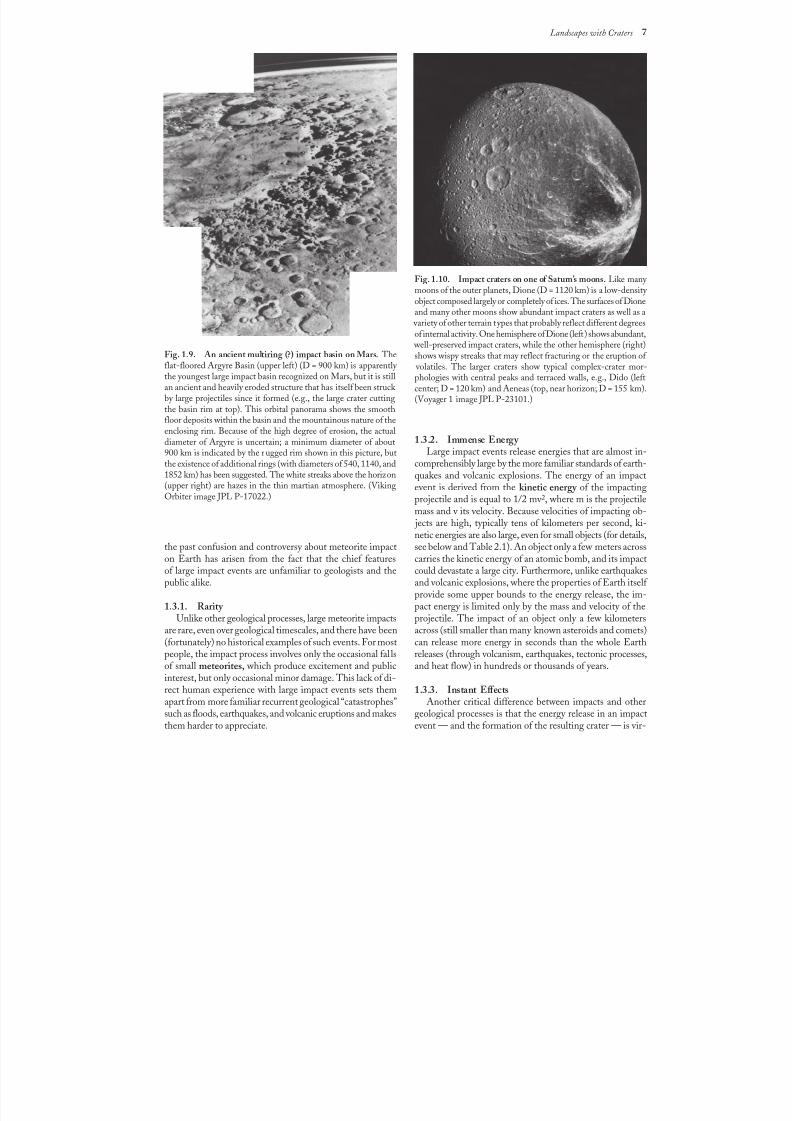
Fig. 1.9. An ancient multiring (?) impact basin on Mars. Theflat-floored Argyre Basin (upper left) (D = 900 km) is apparently the youngest large impact basin recognized on Mars, but it is stillan ancient and heavily eroded structure that has itself been struck by large projectiles since it formed (e.g., the large crater cuttingthe basin rim at top). This orbital panorama shows the smoothfloor deposits within the basin and the mountainous nature of theenclosing rim. Because of the high degree of erosion, the actualdiameter of Argyre is uncertain; a minimum diameter of about
900 km is indicated by the rugged rim shown in this picture, butthe existence of additional rings (with diameters of 540, 1140, and1852 km) has been suggested. The white streaks above the horizon(upper right) are hazes in the thin martian atmosphere. (VikingOrbiter image JPL P-17022.)
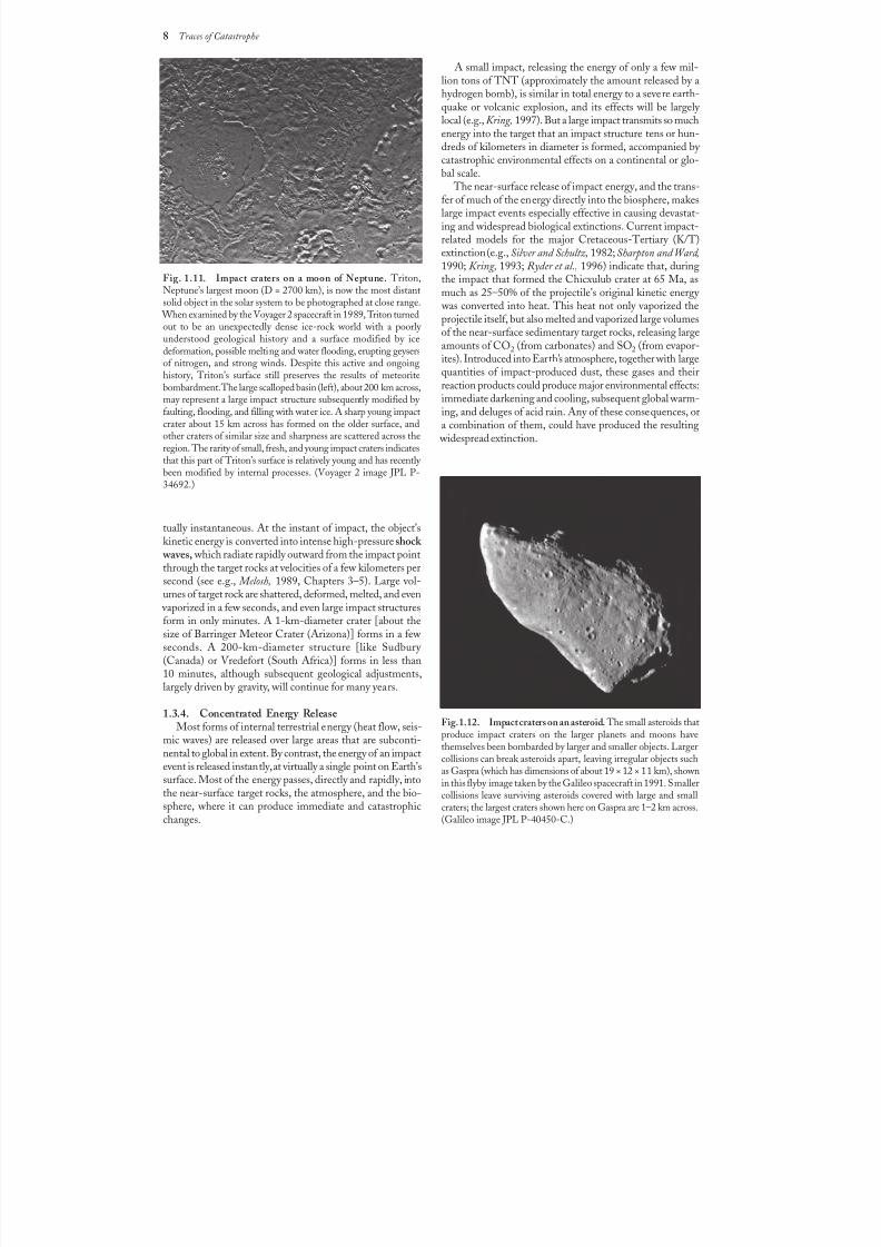
Fig. 1.10. Impact craters on one of Saturn’s moons. Like many moons of the outer planets, Dione (D = 1120 km) is a low-density
object composed largely or completely of ices. The surfaces of Dioneand many other moons show abundant impact craters as well as a
variety of other terrain types that probably reflect different degreesof internal activity. One hemisphere of Dione (left) shows abundant,
well-preserved impact craters, while the other hemisphere (right)shows wispy streaks that may reflect fracturing or the eruption of
volatiles. The larger craters show typical complex-crater mor-phologies with central peaks and terraced walls, e.g., Dido (leftcenter; D = 120 km) and Aeneas (top, near horizon; D = 155 km).(Voyager 1 image JPL P-23101.)
8/8/2019 Traces of Catastrophe - Book
http://slidepdf.com/reader/full/traces-of-catastrophe-book 19/130
8 Traces of Catastrophe
tually instantaneous. At the instant of impact, the object’skinetic energy is converted into intense high-pressure shock
waves, which radiate rapidly outward from the impact pointthrough the target rocks at velocities of a few kilometers persecond (see e.g., Melosh, 1989, Chapters 3–5). Large vol-umes of target rock are shattered, deformed, melted, and even
vaporized in a few seconds, and even large impact structuresform in only minutes. A 1-km-diameter crater [about thesize of Barringer Meteor Crater (Arizona)] forms in a few seconds. A 200-km-diameter structure [like Sudbury (Canada) or Vredefort (South Africa)] forms in less than
10 minutes, although subsequent geological adjustments,largely driven by gravity, will continue for many years.
1.3.4. Concentrated Energy ReleaseMost forms of internal terrestrial energy (heat flow, seis-
mic waves) are released over large areas that are subconti-nental to global in extent. By contrast, the energy of an impactevent is released instantly, at virtually a single point on Earth’ssurface. Most of the energy passes, directly and rapidly, intothe near-surface target rocks, the atmosphere, and the bio-sphere, where it can produce immediate and catastrophicchanges.
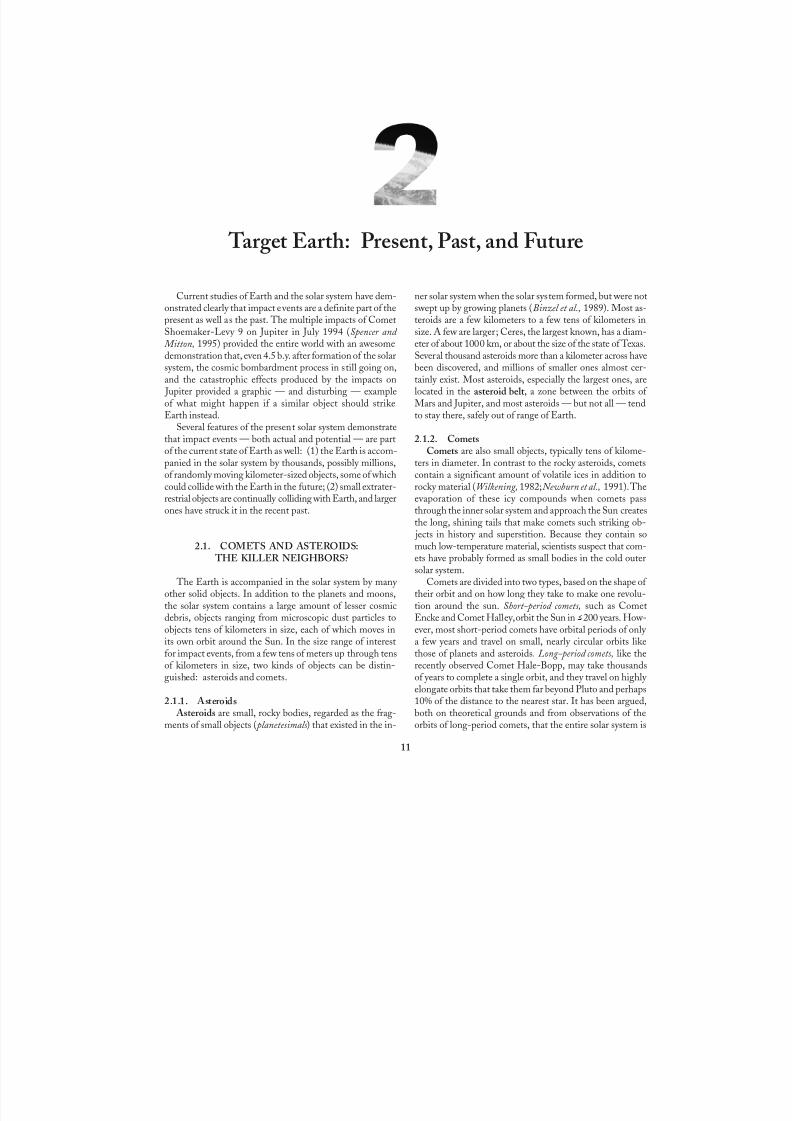
Fig. 1.11. Impact craters on a moon of Neptune. Triton,Neptune’s largest moon (D = 2700 km), is now the most distantsolid object in the solar system to be photographed at close range.
When examined by the Voyager 2 spacecraft in 1989, Triton turnedout to be an unexpectedly dense ice-rock world with a poorly
understood geological history and a surface modified by icedeformation, possible melting and water flooding, erupting geysersof nitrogen, and strong winds. Despite this active and ongoinghistory, Triton’s surface still preserves the results of meteoritebombardment. The large scalloped basin (left), about 200 km across,may represent a large impact structure subsequently modified by faulting, flooding, and filling with water ice. A sharp young impactcrater about 15 km across has formed on the older surface, andother craters of similar size and sharpness are scattered across theregion. The rarity of small, fresh, and young impact craters indicatesthat this part of Triton’s surface is relatively young and has recently been modified by internal processes. (Voyager 2 image JPL P-34692.)
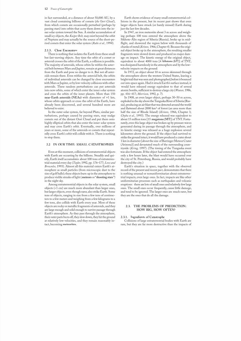
Fig. 1.12. Impact craters on an asteroid. The small asteroids thatproduce impact craters on the larger planets and moons havethemselves been bombarded by larger and smaller objects. Largercollisions can break asteroids apart, leaving irregular objects suchas Gaspra (which has dimensions of about 19 × 12 × 11 km), shownin this flyby image taken by the Galileo spacecraft in 1991. Smallercollisions leave surviving asteroids covered with large and smallcraters; the largest craters shown here on Gaspra are 1–2 km across.(Galileo image JPL P-40450-C.)
A small impact, releasing the energy of only a few mil-lion tons of TNT (approximately the amount released by ahydrogen bomb), is similar in total energy to a severe earth-quake or volcanic explosion, and its effects will be largely local (e.g., Kring, 1997). But a large impact transmits so muchenergy into the target that an impact structure tens or hun-dreds of kilometers in diameter is formed, accompanied by catastrophic environmental effects on a continental or glo-bal scale.
The near-surface release of impact energy, and the trans-fer of much of the energy directly into the biosphere, makeslarge impact events especially effective in causing devastat-ing and widespread biological extinctions. Current impact-related models for the major Cretaceous-Tertiary (K/T)extinction (e.g., Silver and Schultz, 1982; Sharpton and Ward,1990; Kring, 1993; Ryder et al., 1996) indicate that, duringthe impact that formed the Chicxulub crater at 65 Ma, asmuch as 25–50% of the projectile’s original kinetic energy
was converted into heat. This heat not only vaporized theprojectile itself, but also melted and vaporized large volumes
of the near-surface sedimentary target rocks, releasing largeamounts of CO2 (from carbonates) and SO2 (from evapor-ites). Introduced into Earth’s atmosphere, together with largequantities of impact-produced dust, these gases and theirreaction products could produce major environmental effects:immediate darkening and cooling, subsequent global warm-ing, and deluges of acid rain. Any of these consequences, ora combination of them, could have produced the resulting
widespread extinction.

8/8/2019 Traces of Catastrophe - Book
http://slidepdf.com/reader/full/traces-of-catastrophe-book 20/130
Landscapes with Craters 9
1.3.5. Extreme Physical Conditions
The mechanism by which impacts do their work — gen-eration and transmission of intense shock waves through thetarget rocks — is also unfamiliar to many geologists. Undernormal conditions, rocks in Earth’s crust and upper mantleare subjected to static load pressures produced by the weightof overlying rocks. These pressures are less than a few gigapascals (GPa) (1 GPa, a standard unit of pressure, equals104 bar or about 104 atm). Normal geological stresses withinEarth generate relatively low strain rates (typically10–3/sto 10–6/s), and rocks either deform slowly at lower pressuresor fracture at higher pressures when their yield strengths (afew GPa) are exceeded. The general tendency of terrestrial
rocks to fracture when the pressure gets too high, thus re-
leasing the pressure, limits the pressure buildup in ordinary geological processes (e.g., earthquakes) to a few GPa.
These “normal” conditions do not exist in impact events. The rapid release of large amounts of energy in such eventsputs too much sudden stress on the target rocks for them torespond in the normal way. Typical impact velocities of tensof kilometers per second far exceed the velocities of sound inthe target rocks (typically 5–8 km/s). The resulting impact-produced shock waves travel through the target rocks at su-personic velocities, and they impose intense stresses on therocks without giving them time to give way by normal de-formation. In the shock-wave environment, transient pres-
Fig. 1.13. Bombardment rates and crater formation during geologic time. This graph summarizes the results of studies in which the
highly variable numbers of craters present on different lunar surfaces have been used to reconstruct the meteorite bombardment rate within the Earth-Moon system during the last 4 b.y. Lunar crater densities [expressed as the total number (N) of craters with D > 4 kmper square kilometer of surface] have been measured from spacecraft photographs of various highlands and maria surfaces whose ageshave been determined from samples returned by the Apollo (A) and Russian robotic Luna (L) missions. The data (bounded by two solidlines that indicate estimated uncertainties) are most precise for the well-dated maria surfaces, which have ages of 3.7–3.2 Ga. Ages of theolder highland surfaces are not as well determined, but it is clear that crater-production rates before 3.8 Ga were much higher (>100×)than in more recent times. The much lower crater formation rate after 3.8 Ga is not statistically different from a constant value (dashedline); this rate is also consistent with values estimated from the small population of preserved terrestrial impact structures. Age values forthe large lunar craters Copernicus (about 1 Ga) and Tycho (about 100 Ma) have been indirectly determined from Apollo samplescollected elsewhere on the Moon. (From Hörz et al., 1991, Fig. 4.15, p. 84.)

8/8/2019 Traces of Catastrophe - Book
http://slidepdf.com/reader/full/traces-of-catastrophe-book 21/130
10 Traces of Catastrophe
sures may exceed 500 GPa at the impact point and may beas high as 10–50 GPa throughout large volumes of thesurrounding target rock. Transient strain rates may reach104/s–106/s, orders of magnitude higher than those in ordi-nary geological processes. At the higher shock pressures(>60GPa), shock-produced temperatures can exceed2000°C, and rapid, large-scale melting occurs immediately after the shock wave has passed.
1.3.6. Unique Deformation Effects The extreme physical conditions of pressure, tempera-
ture, and strain imposed by transient shock waves produceunique effects (e.g., mineral deformation, melting) in therocks and mineral grains through which they pass. Theseshock-metamorphic effects are distinct from features pro-duced by normal geological deformation, and they are now generally accepted as unique products of impact events (forreviews and references, see French and Short, 1968; Stöffler,1972, 1974; Stöffler and Langenhorst, 1994; Grieve et al.,1996).
Shock-metamorphic effects (or “shock effects”) have beencrucial in establishing the importance of extraterrestrial im-pact events. Preserved meteorites around an impact cratercan provide definite evidence of an impact origin, but only asmall fraction of terrestrial impact structures (about a dozen)
have actual preserved meteorites associated with them. Thesestructures are all relatively small and geologically young. TheBarringer Meteor Crater (Arizona), 1.2 km in diameter andabout 50,000 years old (Fig. 1.1), is the largest member of this group.
The absence of meteorite fragments around older impactcraters results from two causes: (1) the projectile itself is alsosubjected to the intense shock waves generated by the im-
pact, and it is almost completely melted and vaporized;and (2) all meteorites are partly to completely composed of nickel-iron metal, and even surviving fragments of the pro-
jectile tend to be rapidly destroyed by surface weathering,except in the driest desert regions or on polar icecaps.
The rapid destruction of meteorites means that other linesof evidence must be used to identify older or deeply erodedterrestrial impact structures. Shock-metamorphic effects canbe preserved in rocks for periods of 106–109 years, and they provide a unique means of identifying impact structures, es-pecially ones that are old, deeply eroded, or both (Frenchand Short, 1968). The great majority of currently knownimpact structures (currently over 150) have no preserved me-teorites, but have been identified by the discovery of shock-metamorphic effects in their rocks (Grieve, 1991; Grieve et al., 1995; Grieve and Pesonen, 1992, 1996).
8/8/2019 Traces of Catastrophe - Book
http://slidepdf.com/reader/full/traces-of-catastrophe-book 22/130
8/8/2019 Traces of Catastrophe - Book
http://slidepdf.com/reader/full/traces-of-catastrophe-book 23/130
12 Traces of Catastrophe
in fact surrounded, at a distance of about 50,000 AU, by a vast cloud containing billions of comets (the Oort Cloud ),from which comets are occasionally perturbed (perhaps by passing stars) into orbits that carry them down into the in-ner solar system toward the Sun. A similar accumulation of small icy objects, the Kuiper Belt, may exist beyond the orbitof Neptune and may actually be the source of the short-pe-riod comets that enter the solar system (Rahe et al., 1994).
2.1.3. Close Encounters There is nothing that isolates the Earth from these small
but fast-moving objects. Any time the orbit of a comet orasteroid crosses the orbit of the Earth, a collision is possible.
The majority of asteroids, whose orbits lie within the aster-oid belt between Mars and Jupiter, remain at great distancesfrom the Earth and pose no danger to it. But not all aster-oids remain there. Even within the asteroid belt, the orbitsof individual asteroids can be changed by close encounters
with Mars or Jupiter, or by low-velocity collisions with otherasteroids. These random perturbations can put asteroidsinto new orbits, some of which enter the inner solar systemand cross the orbits of the inner planets. More than 150near-Earth asteroids (NEAs) with diameters of >1 km,
whose orbits approach or cross the orbit of the Earth, havealready been discovered, and several hundred more arebelieved to exist.
In the outer solar system, far beyond Pluto, similar per-turbations, perhaps caused by passing stars, may nudgecomets out of the distant Oort Cloud and put them ontohighly elliptical orbits that also enter the inner solar systemand may cross Earth’s orbit. Eventually, over millions of
years or more, some of the asteroids or comets that repeat-edly cross Earth’s orbit will collide with it. There is nothing
to stop them.
2.2 IN OUR TIME: SMALL CATASTROPHES
Even at this moment, collisions of extraterrestrial objects with Earth are occurring by the billions. Steadily and qui-etly, Earth itself accumulates about 100 tons of extraterres-trial material every day (Taylor, 1992, pp. 176–177; Love and Brownlee, 1993). Almost all this material enters Earth’s at-mosphere as small particles (from microscopic dust to thesize of golf balls); these objects burn up in the atmosphere toproduce visible streaks of light (meteors or “shooting stars”)in the night sky.
Among extraterrestrial objects in the solar system, smallobjects (<1 cm) are much more abundant than larger ones,but larger objects, even though rarer, also strike Earth. Sometens of objects, ranging in size from a few tens of centime-ters to a few meters and weighing from a few kilograms to afew tons, also collide with Earth every year. Most of theseobjects are rocky or metallic fragments of asteroids, and they are large enough and solid enough to survive passage throughEarth’s atmosphere. As they pass through the atmosphere,their outer parts burn off, they slow down, they hit the groundat relatively low velocities, and they remain reasonably in-tact, becoming meteorites.
Earth shows evidence of many small extraterrestrial col-lisions in the present, but its recent past shows that evenlarger objects have struck (or barely missed) Earth during
just the last few decades.In 1947, an iron meteorite about 3 m across and weigh-
ing perhaps 100 tons entered the atmosphere above theSikhote-Alin region of Siberia (Russia), broke up in mid-flight, and showered the region below with thousands of
chunks of metal (Krinov, 1966, Chapter 4). Because the origi-nal object broke up in the atmosphere, the resulting smallerfragments were slowed down and produced no major dam-age on impact. The kinetic energy of the original object,equivalent to about 4000 tons [4 kilotons (kT)] of TNT,
was dissipated harmlessly in the atmosphere and by the low- velocity impacts on the ground.
In 1972, an object about 10 m across skimmed throughthe atmosphere above the western United States, leaving abright trail that was seen and photographed, before it bouncedout into space again. Had it struck Earth’s surface instead, it
would have released energy equivalent to that of severalatomic bombs, sufficient to destroy a large city (Weaver, 1986,pp. 416–417; Morrison, 1992, p. 7).
In 1908, an even larger object, perhaps 30–50 m across,exploded in the sky above the Tunguska River of Siberia (Rus-sia), producing an air blast that was detected around the worldand flattened about 2000 km2 of forest (an area more thanhalf the size of Rhode Island) (Krinov, 1966, Chapter 3;Chyba et al., 1993). The energy released was equivalent toabout 15 million tons [15 megatons (MT)] of TNT. Fortu-nately, even this large object was broken up by pressure wavesgenerated during its passage through the atmosphere, andits kinetic energy was released as a huge explosion severalkilometers above the ground. If the object had survived to
strike the ground intact, it would have produced a crater about1 km in diameter [about the size of Barringer Meteor Crater(Arizona)] and devastated much of the surrounding coun-tryside (Kring, 1997). (The timing of the Tunguska event
was also fortunate. If the object had entered the atmosphereonly a few hours later, the blast would have occurred overthe city of St. Petersburg, Russia, and would probably havedestroyed the city.)
Earth’s situation in space, together with the observedrecord of the present and recent past, demonstrates that thereis nothing unusual or nonuniformitarian about extraterres-trial impacts, even large ones. In fact, impacts are like otheruniformitarian processes such as earthquakes and volcanic
eruptions: there are lots of small ones and relatively few largeones. The small ones occur frequently, cause little damage,and tend to be ignored. The larger ones are much rarer, butthey are the ones that do all the damage.
2.3. THE PROBLEMS OF PREDICTION:HOW BIG, HOW OFTEN?
2.3.1. Ingredients of CatastropheCollisions of large extraterrestrial bodies with Earth are
rare, but they are far more destructive than the impacts of
8/8/2019 Traces of Catastrophe - Book
http://slidepdf.com/reader/full/traces-of-catastrophe-book 24/130
Target Earth: Present, Past, and Future 13
smaller objects. Larger and heavier objects not only possessmore kinetic energy than smaller ones, but they are also lessaffected by Earth’s atmosphere. They are not slowed down,they survive intact to the ground, and their entire originalkinetic energy is delivered to Earth’s surface. Objects no morethan a few tens of meters across may be massive enough(and coherent enough, especially if they are iron meteorites)to pass through the atmosphere without being slowed and
to strike the ground at their original cosmic velocities. Typical cosmic velocities are high. The minimum impact
velocity for collisions with Earth is 11.2 km/s; this is, by definition, equal to the escape velocity for an object launchedinto space from Earth’s surface. The maximum possible im-pact velocity onto Earth is the sum of two separate veloci-ties: (1) The velocity of the impacting object in its orbitaround the Sun (heliocentric velocity). This quantity, whichcan also be thought of as the escape velocity from the solarsystem, is about 42 km/s at the orbit of Earth. (2) The or-bital velocity of Earth itself around the Sun, which is about30km/s. The maximum possible impact velocity on Earthis the simple sum of these two velocities, or 72 km/s. How-ever, the orbits of Earth and the colliding object will gener-ally be inclined to one another; the two velocities willtherefore add geometrically (as a vector sum), producingEarth-encounter velocities ( geocentric velocities) between thesetwo limits. Typical Earth-encounter velocities for asteroidsare 15–25 km/s (Chyba et al., 1994). Comets tend to havehigher encounter velocities, e.g., as much as 60 km/s forComet Halley. At such speeds, these objects carry as muchkinetic energy as 20–50× their weight in TNT, and all thisenergy is released when they strike the Earth.
Because impact velocities are high, the kinetic energy (= 1/2 mv 2) of even small objects is also high. A stony mete-
orite only 6 m in diameter, colliding with the Earth at20 km/s, releases as much energy [8.3 × 10¹³ joules ( J) or20,000 tons (20 kT) of TNT] as an atomic bomb (see
Table2.1). The impact of a larger object, such as a moder-ate-sized comet or asteroid only a few kilometers across, re-leases in seconds amounts of energy measured in millions oreven billions of MT (1 MT = 106 tons of TNT or 4.2 ×10¹⁵ J). For comparison, the total energy released by theEarth, through volcanism, earthquakes, and heat flow, isabout 1.3× 10²¹ J/yr, or about 310,000 MT/yr (Fowler, 1993,p. 226). A collision with a modest-sized asteroid thusreleases in a few seconds more energy than the entire Earthreleases in hundreds or thousands of years. Fortunately for
terrestrial life and civilization, these larger catastrophes arerare, even over geological timescales of millions of years.
2.3.2. Uncertain EstimatesBut just how rare is “rare”? How often is an impact crater
of a given size produced on Earth? How often will bodies of a given size collide with Earth in the future? Scientists at-tempting to solve these problems for Earth (or any otherplanet) are faced with three complex and interrelated ques-tions: (1) How often will an extraterrestrial object of a givensize strike Earth? (2) How much energy (determined by theobject’s mass and impact velocity) will be released by the
event? (3) How large a crater will be formed by this amountof energy?
Attempting to answer these questions causes major diffi-culties. Impact is a random process, not a regular one, and itis difficult to make a precise statistical estimate from only asmall number of recorded events. The preserved terrestrialcrater population is small; worse, it is biased toward youngerand larger structures because of erosion and other postim-
pact processes. Better statistics are available from the more well-preserved lunar and planetary cratering records, but toapply this information to Earth requires corrections for dif-ferent planetary gravity fields, target characteristics, andthe variation of impact rates at different locations within thesolar system. Finally, calculations of crater sizes depend on alarge number of complicated factors: projectile characteris-tics (mass, density, physical properties, impact velocity,impact angle), target characteristics (structure, physical prop-erties), the partitioning of the projectile’s original kineticenergy into various forms (mechanical, kinetic, seismic, ther-mal) within the target, and the relationships between im-pact energy and crater size for various projectiles, targets,and impact velocities.
Efforts to determine impact frequencies date back to be-fore the Apollo program and the planetary missions of thelast few decades, and, despite the difficulties, much progresshas been made. Many workers have used a large range of different astronomical and planetary data: the present mea-sured impact rate of small bodies on the Earth; the numberand sizes of known asteroids and comets; and the numberand size of impact craters observed on the better-preservedsurfaces of other planets, particularly the Moon, Mars, and(more recently) Venus (for reviews and different examples,see Taylor, 1982, Chapter 3; 1992, Chapter 4; Hörz et al.,
1991; papers in Gehrels, 1994). Other scientists have calcu-lated terrestrial bombardment rates from the small but grow-ing population of preserved terrestrial craters (Grieve, 1991;Grieve and Shoemaker, 1994; Grieve and Pesonen, 1992,1996; Shoemaker and Shoemaker, 1996). The various theo-retical problems of energy partitioning and crater size havebeen extensively addressed in numerous theoretical andlaboratory studies (e.g., O’Keefe and Ahrens, 1975, 1977,1993; Ahrens and O’Keefe, 1977; papers in Roddy et al.,1977; Holsapple and Schmidt, 1982, 1987; for reviews andliterature, see also Melosh, 1989, Chapter 7).
Even with the large amount of observational, theoretical,and laboratory data now available, the uncertainties in such
estimates remain large. Individual estimates of the frequency of impact on Earth for objects of the same size vary by fac-tors of 5–10×, especially for larger objects. (Compare, e.g.,the various estimates of Bottke et al., 1994; Neukum and Ivanov, 1994; Grieve and Shoemaker, 1994.) The materialin Table 2.1 presents approximate estimates of terrestrialimpact frequencies, energies, and resulting crater sizes. Thesedata represent a combination of various current estimates,but they are only approximate and should be used only forgeneral illustration. The uncertainties, in both the databasesand the mathematical models used, are still too great toallow more precise estimates.

8/8/2019 Traces of Catastrophe - Book
http://slidepdf.com/reader/full/traces-of-catastrophe-book 25/130
TABLE 2.1. Terrestrial meteorite impact craters: Crater sizes, projectile sizes, frequencies, and comparable
Crater Approximate Energy Impact Frequency Mean Impact IntervalDiameter Projectile Diameter Energy ( J) (TNT Equivalent) (No. per m.y., Whole Earth) (Tmean, Whole Earth) Compa
35 m 2 m 2.1 E + 12 500 tons 250,000 4 yr Minim
Larges(“Snow
75 m 4 m 1.9 E + 13 4,500 tons 69,000 15 yr Larges(Helig
120 m 6 m 8.3 E + 13 20,000 tons 28,000 35 yr Atomi(Hiros
450 m 23 m 4.2 E + 15 1 MT 2,700 370 yr “Typic
1 km 50 m 4.6 E + 16 11 MT 640 1,600 yr Wolfe Pretori
1.1 km 55 m 6.2 E + 16 15 MT 540 1,900 yr Barrin TungusMt. St
1.8 km 90 m 2.5 E + 17 60 MT 230 4,400 yr San FrLarges
3.1 km 155 m 1.3 E + 18 310 MT 83 12,000 yr Mt. St(total e
5 km 250 m 5.7 E + 18 1,400 MT 35 28,500 yr GardnGoat P
6.9 km 350 m 1.5 E + 15 3,600 MT 20 51,000 yr Larges
(Chile,
7.2 km 360 m 1.7 E + 15 3,700 MT 18 55,000 yr Krakat(Total
10 km 500 m 4.6 E + 19 11,000 MT 10 100,000 yr Lake MBosumOasis,

8/8/2019 Traces of Catastrophe - Book
http://slidepdf.com/reader/full/traces-of-catastrophe-book 26/130
TABLE 2.1. (continued).
Crater Approximate Energy Impact Frequency Mean Impact IntervalDiameter Projectile Diameter Energy ( J) (TNT Equivalent) (No. per m.y., Whole Earth) (Tmean, Whole Earth) Compa
12.2 km 610 m 8.4 E + 19 20,000 MT 7.1 142,000 yr Tambo(Total
20 km 1 km 3.7 E + 20 87,000 MT 2.9 350,000 yr HaughRocheRies C
31 km 1.5 km 1.3 E + 21 310,000 MT 1.4 720,000 yr Total a(Heat f
50 km 2.5 km 5.8 E + 21 1.3 E + 6 MT 0.22 4.5 m.y. MontaCharleSiljan,
100 km 5 km 4.6 E + 22 1.1 E + 7 MT 0.04 26 m.y. ManicPopiga
200 km 10 km 3.7 E + 23 8.7 E + 7 MT 0.007 150 m.y. Larges(originSudbuChicxu
Atmospheric effects on small projectiles neglected. (In real impacts, projectiles <50 m are probably destroyed in the atmosphere.)Frequency distributions from Grieve and Shoemaker (1994) and Neukum and Ivanov (1994).Spherical projectile: V = 4/3(π)r3.Projectile density = 3500 kg/m3 (stony meteorite).Impact velocity = 20 km/s vertical impact.Crater diameter/projectile diameter is constant, = 20 for all crater sizes.Crater-forming energy = projectile kinetic energy = 1/2 mv 2.
J = joules, m.y. = million years, M = Richter magnitude, E = exponential notation (E + 6 = 1 million, etc.), MT = megatons.
Impact structures shown in boldface type.
8/8/2019 Traces of Catastrophe - Book
http://slidepdf.com/reader/full/traces-of-catastrophe-book 27/130
16 Traces of Catastrophe
Geologically based estimates for the terrestrial impact ratehave been obtained from the number of large (D > 20 km)impact structures identified in stable, well-preserved regionsof Earth (Grieve, 1991; Grieve and Shoemaker, 1994; Shoe-maker and Shoemaker, 1996]. This value, (5.6 ± 2.8) × 10–15
craters/km2/yr, is comparable with that deduced from astro-nomical data (chiefly from crater counts on the Moon’s sur-face), although the stated 50% uncertainty is probably a
minimum value. This rate implies that, over the whole Earth,a few (perhaps 1–5) craters of this size (D > 20 km) shouldbe produced every million years or so by the impact of projectiles >1–2 km in diameter. In these models, the aver-age impact frequency varies approximately with the inversesquare of the crater diameter, implying that about 10 cratersof diameter >10 km should form in the same million-
year period, while a crater >100 km in diameter should beformed every 10 m.y. or so. Other models for impact fre-quencies (e.g., Neukum and Ivanov, 1994) yield numbersof craters that are lower by factors of 5–10, especially forlarger structures.
Nevertheless, these estimates are useful approximations,and they demonstrate that even very large impacts are notan unusual phenomenon when one thinks in terms of geo-logical periods of time.
2.3.3. An Uncertain Future? The frequency with which extraterrestrial objects collide
with Earth, and the sizes of craters produced by the colli-sions, are not just interesting scientific problems. They arematters for serious concern about the future of our society,perhaps even of our species. We know that extraterrestrialbodies collide with Earth today, we have demonstrated thatthey have collided with it in the past, and we must face the
fact that they will continue to collide with it in the future.
It is not a question of whether such collisions will occur;the only questions are when, how big, and what the effects
will be. The hazards of such future collisions have been discussed
in detail elsewhere (Chapman and Morrison, 1989, 1994; Morrison, 1992; Gehrels, 1994; Verschuur, 1996). Large im-pact events are rare, but they cannot be ignored just for thatreason. Such events are unpredictable and might happen at
any moment. The impact of an object only 50 m across, form-ing a crater only a kilometers in diameter [e.g., BarringerMeteor Crater (Arizona)], would totally devastate an area of several thousand square kilometers around the impact site(Kring, 1997). The probability of a larger event, sufficient tocripple or possibly destroy our current interconnected andtechnology-dependent civilization, although small, is very real (Chapman and Morrison, 1994), and we do not yet know enough to evaluate the danger.
Although much of the concern for assessing and remov-ing impact hazards lies in other areas, particularly social andpolitical, the scientific study of impact events can play a cru-cial role in understanding and possibly preventing the cata-strophic damage that would be caused by a large impact eventin the future. The geological structures left by past impactevents can give us information about the frequency of largeimpact events, the sizes of the projectiles, the energy released,and the environmental damage produced over regional orglobal distances. At the same time, continued observation of the solar system can inventory the existing population of near-Earth asteroids and comets and can help estimate the chancesof future collisions. With such data, the threat from extra-terrestrial objects can be better evaluated, and people andgovernments can determine what — if anything — can bedone to avoid a catastrophic disaster in the future.
8/8/2019 Traces of Catastrophe - Book
http://slidepdf.com/reader/full/traces-of-catastrophe-book 28/130
Formation of Impact Craters 17
17
The processes by which large impact craters form, andthe sudden releases of huge quantities of energy involved,cannot be duplicated in the laboratory, and, fortunately, nosuch structure has formed during recorded human history.All our knowledge about large impact structures is thereforeindirect, and it has come from combining several areas of once-separate research: theoretical and experimental stud-ies of shock waves (for reviews and literature, see Melosh,1989), experimental production of small craters (e.g., Gault et al., 1968; Gault, 1973; Holsapple and Schmidt, 1982, 1987;papers in Roddy et al., 1977), and geological studies of largerterrestrial impact structures (Shoemaker, 1963; Dence, 1968;Dence et al., 1977; Grieve and Cintala, 1981; Grieve et al.,
1981; Schultz and Merrill, 1981; Stöffler et al., 1988). Thecratering process is complex, many details are still uncertain,and neither calculations nor predictions can be made withfirm confidence. But these studies provide the essential ba-sis for understanding how impact craters form and for deci-phering the geological features they display.
3.1. SHOCK WAVES ANDCRATER FORMATION
The general term “impact crater” is used here to desig-nate a hypervelocity impact crater , the structure formed by
a cosmic projectile that is large enough and coherent enoughto penetrate Earth’s atmosphere with little or no decelera-tion and to strike the ground at virtually its original cosmic
velocity (>11 km/s). Such projectiles tend to be relatively large, perhaps >50 m in diameter for a stony object and >20mfor a more coherent iron one.
Smaller projectiles, typically a few meters or less in size,behave differently in passing through the atmosphere. They lose most or all of their original velocity and kinetic energy in the atmosphere through disintegration and ablation, andthey strike the ground at speeds of no more than a few hun-
dred meters per second. In such a low-velocity impact, theprojectile penetrates only a short distance into the target (de-pending on its velocity and the nature of the target mate-rial), and the projectile’s momentum excavates a pit that isslightly larger than the projectile itself. The projectile sur-
vives, more or less intact, and much of it is found in thebottom of the pit. Such pits, sometimes called penetrationcraters or penetration funnels, are typically less than a few tens of meters in diameter.
Examples of these features include Brenham (Kansas),the many small pits made by the Sikhote-Alin (Russia) me-teorite shower in 1947, and the pit dug by the largest pieceof the Kirin (China) meteorite fall in 1976. The process of
excavation is strictly a mechanical one, and high-pressureshock waves are not produced.In sharp contrast, a hypervelocity impact crater starts to
form at the instant that an extraterrestrial object strikes theground surface at its original cosmic velocity. These impact
velocities are much greater than the speed of sound in thetarget rocks, and the crater is produced by intense shock waves that are generated at the point of impact and radiateoutward through the target rocks. Shock waves are intense,transient, high-pressure stress waves that are not producedby ordinary geological processes (for details, see Melosh, 1989,Chapter 3 and references therein). Peak shock pressures pro-duced at typical cosmic encounter velocities may reach sev-
eral hundred GPa. These pressure are far above the stresslevels (~1 GPa) at which terrestrial rocks undergo normalelastic and plastic deformation, and the shock waves pro-duce unique and permanent deformation effects in the rocksthrough which they pass.
The shock waves radiate from the impact point at high velocities that may exceed 10 km/s, much greater than thespeed of sound in the target rocks. As they expand, they in-teract with the original ground surface to set a large volumeof the target rock into motion, thus excavating the impactcrater. The formation of an impact crater by shock waves,
Formation of Impact Craters
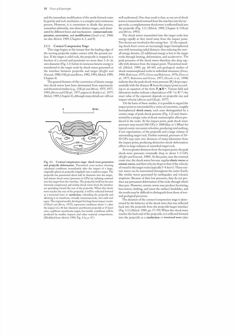
8/8/2019 Traces of Catastrophe - Book
http://slidepdf.com/reader/full/traces-of-catastrophe-book 29/130
18 Traces of Catastrophe
and the immediate modification of the newly formed craterby gravity and rock mechanics, is a complex and continuousprocess. However, it is convenient to divide this process,somewhat arbitrarily, into three distinct stages, each domi-nated by different forces and mechanisms: contact and com-pression, excavation, and modification (Gault et al., 1968;see also Melosh, 1989, Chapters 4, 5, and 8).
3.1.1. Contact/Compression Stage This stage begins at the instant that the leading edge of
the moving projectile makes contact with the ground sur-face. If the target is solid rock, the projectile is stopped in afraction of a second and penetrates no more than 1–2× itsown diameter (Fig. 3.1) before its immense kinetic energy istransferred to the target rocks by shock waves generated atthe interface between projectile and target (Kieffer and Simonds, 1980; O’Keefe and Ahrens, 1982, 1993; Melosh, 1989,Chapter 4).
The general features of this conversion of kinetic energy into shock waves have been determined from experimentsand theoretical studies (e.g., O’Keefe and Ahrens, 1975, 1977,1993; Ahrens and O’Keefe, 1977; papers in Roddy et al., 1977; Melosh, 1989, Chapter 4), although many details are still not
well understood. One clear result is that, as one set of shock waves is transmitted outward from the interface into the tar-get rocks, a complementary shock wave is reflected back intothe projectile (Fig. 3.1) ( Melosh, 1989, Chapter 4; O’Keefe and Ahrens, 1993).
The shock waves transmitted into the target rocks loseenergy rapidly as they travel away from the impact point.
Two factors are involved in this energy loss: (1) the expand-
ing shock front covers an increasingly larger hemisphericalarea with increasing radial distance, thus reducing the over-all energy density; (2) additional energy is lost to the targetrocks through heating, deformation, and acceleration. Thepeak pressures of the shock waves therefore also drop rap-idly with distance from the impact point. Theoretical mod-els ( Melosh, 1989, pp. 60–66) and geological studies of shock-metamorphosed rocks in individual structures (Dence,1968; Robertson, 1975; Grieve and Robertson, 1976; Dence et al., 1977; Robertson and Grieve, 1977; Dressler et al., 1998)indicate that the peak shock-wave pressure (Ps) drops expo-nentially with the distance R from the impact point accord-ing to an equation of the form P
s ααααα R –n. Various field and
laboratory studies indicate a dependence of R –2 to R –4.5; theexact value of the exponent depends on projectile size andimpact velocity ( Ahrens and O’Keefe, 1977).
On the basis of these studies, it is possible to regard theimpact point as surrounded by a series of concentric, roughly hemispherical shock zones, each zone distinguished by acertain range of peak shock pressure (Fig. 3.2) and charac-terized by a unique suite of shock-metamorphic effects pro-duced in the rocks. At the impact point, peak shock-wavepressures may exceed 100 GPa (= 1000 kbar or 1 Mbar) fortypical cosmic encounter velocities, producing total melting,if not vaporization, of the projectile and a large volume of
surrounding target rock. Further outward, pressures of 10–50 GPa may exist over distances of many kilometers fromthe impact point, producing distinctive shock-deformationeffects in large volumes of unmelted target rock.
At even greater distances from the impact point, the peak shock-wave pressures eventually drop to about 1–2 GPa(Kieffer and Simonds, 1980). At this point, near the eventualcrater rim, the shock waves become regular elastic waves orseismic waves, and their velocity drops to that of the velocity of sound in the target rocks (typically 5–8 km/s). These seis-mic waves can be transmitted throughout the entire Earth,like similar waves generated by earthquakes and volcaniceruptions. Because of their low pressures, they do not pro-
duce any permanent deformation of the rocks through whichthey pass. However, seismic waves may produce fracturing,brecciation, faulting, and (near the surface) landslides, andthe results may be difficult to distinguish from those of nor-mal geological processes.
The duration of the contact/compression stage is deter-mined by the behavior of the shock wave that was reflectedback into the projectile from the projectile/target interface(Fig. 3.1) ( Melosh, 1989, pp. 57–59). When this shock wavereaches the back end of the projectile, it is reflected forwardinto the projectile as a rarefaction or tensional wave (also
Fig. 3.1. Contact/compression stage: shock-wave generationand projectile deformation. Theoretical cross-section showingcalculated conditions immediately after the impact of a large,originally spherical, projectile (stippled) onto a uniform target. Theprojectile has penetrated about half its diameter into the target,and intense shock waves (pressures in GPa) are radiating outward
into the target from the interface. The projectile itself has becomeintensely compressed, and similar shock waves from the interfaceare spreading toward the rear of the projectile. When this shock
wave reaches the rear of the projectile, it will be reflected forwardas a tensional wave or rarefaction, unloading the projectile andallowing it to transform, virtually instantaneously, into melt and
vapor. The original model, developed for large lunar impact events(O’Keefe and Ahrens, 1975), represents conditions about 1 s afterthe impact of a 46-km-diameter anorthosite projectile at 15km/sonto a gabbroic anorthosite target, but similar conditions will beproduced by smaller impacts and other material compositions.(Modified from Melosh, 1989, Fig. 4.1a, p. 47.)
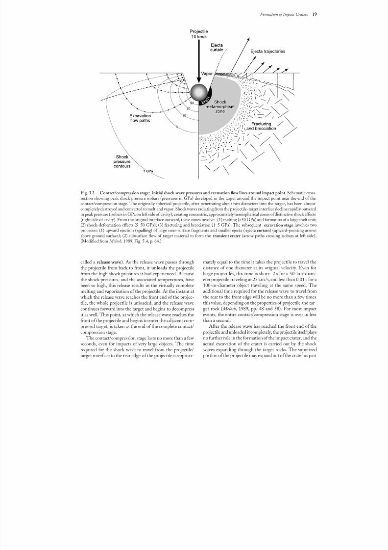
8/8/2019 Traces of Catastrophe - Book
http://slidepdf.com/reader/full/traces-of-catastrophe-book 30/130
Formation of Impact Craters 19
called a release wave). As the release wave passes throughthe projectile from back to front, it unloads the projectilefrom the high shock pressures it had experienced. Becausethe shock pressures, and the associated temperatures, havebeen so high, this release results in the virtually completemelting and vaporization of the projectile. At the instant at
which the release wave reaches the front end of the projec-tile, the whole projectile is unloaded, and the release wavecontinues forward into the target and begins to decompressit as well. This point, at which the release wave reaches thefront of the projectile and begins to enter the adjacent com-pressed target, is taken as the end of the complete contact/compression stage.
The contact/compression stage lasts no more than a few seconds, even for impacts of very large objects. The timerequired for the shock wave to travel from the projectile/target interface to the rear edge of the projectile is approxi-
mately equal to the time it takes the projectile to travel thedistance of one diameter at its original velocity. Even forlarge projectiles, this time is short: 2 s for a 50-km-diam-eter projectile traveling at 25 km/s, and less than 0.01 s for a100-m-diameter object traveling at the same speed. Theadditional time required for the release wave to travel from
the rear to the front edge will be no more than a few timesthis value, depending on the properties of projectile and tar-get rock ( Melosh, 1989, pp. 48 and 58). For most impactevents, the entire contact/compression stage is over in lessthan a second.
After the release wave has reached the front end of theprojectile and unloaded it completely, the projectile itself playsno further role in the formation of the impact crater, and theactual excavation of the crater is carried out by the shock
waves expanding through the target rocks. The vaporizedportion of the projectile may expand out of the crater as part
, ,
, ,
, , ,
, , ,
, , ,
,,
Fig. 3.2. Contact/compression stage: initial shock-wave pressures and excavation flow lines around impact point. Schematic cross-section showing peak shock pressure isobars (pressures in GPa) developed in the target around the impact point near the end of thecontact/compression stage. The originally spherical projectile, after penetrating about two diameters into the target, has been almostcompletely destroyed and converted to melt and vapor. Shock waves radiating from the projectile-target interface decline rapidly outwardin peak pressure (isobars in GPa on left side of cavity), creating concentric, approximately hemispherical zones of distinctive shock effects(right side of cavity). From the original interface outward, these zones involve: (1) melting (>50 GPa) and formation of a large melt unit;(2) shock-deformation effects (5–50 GPa); (3) fracturing and brecciation (1–5 GPa). The subsequent excavation stage involves twoprocesses: (1) upward ejection (spalling ) of large near-surface fragments and smaller ejecta (ejecta curtain) (upward-pointing arrowsabove ground surface); (2) subsurface flow of target material to form the transient crater (arrow paths crossing isobars at left side).(Modified from Melosh, 1989, Fig. 5.4, p. 64.)
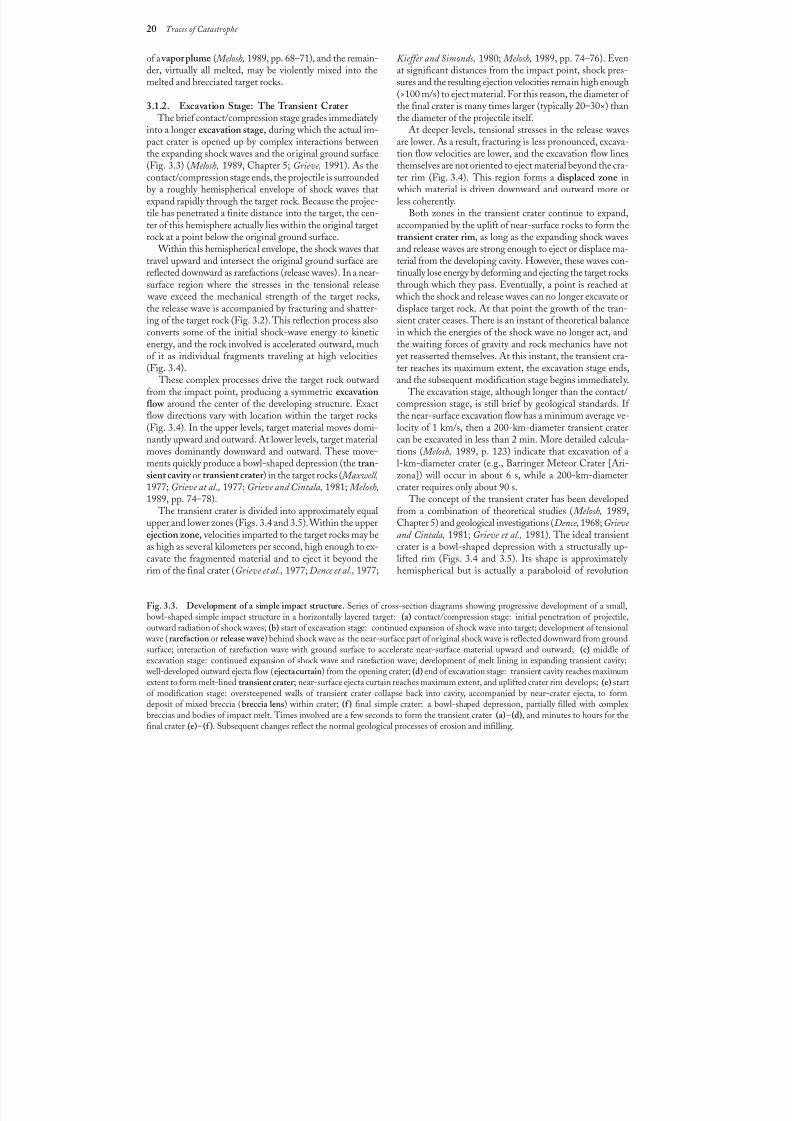
8/8/2019 Traces of Catastrophe - Book
http://slidepdf.com/reader/full/traces-of-catastrophe-book 31/130
20 Traces of Catastrophe
of a vapor plume ( Melosh, 1989, pp. 68–71), and the remain-der, virtually all melted, may be violently mixed into themelted and brecciated target rocks.
3.1.2. Excavation Stage: The Transient Crater The brief contact/compression stage grades immediately
into a longer excavation stage, during which the actual im-pact crater is opened up by complex interactions between
the expanding shock waves and the original ground surface(Fig. 3.3) ( Melosh, 1989, Chapter 5; Grieve, 1991). As thecontact/compression stage ends, the projectile is surroundedby a roughly hemispherical envelope of shock waves thatexpand rapidly through the target rock. Because the projec-tile has penetrated a finite distance into the target, the cen-ter of this hemisphere actually lies within the original targetrock at a point below the original ground surface.
Within this hemispherical envelope, the shock waves thattravel upward and intersect the original ground surface arereflected downward as rarefactions (release waves). In a near-surface region where the stresses in the tensional release
wave exceed the mechanical strength of the target rocks,the release wave is accompanied by fracturing and shatter-ing of the target rock (Fig. 3.2). This reflection process alsoconverts some of the initial shock-wave energy to kineticenergy, and the rock involved is accelerated outward, muchof it as individual fragments traveling at high velocities(Fig.3.4).
These complex processes drive the target rock outwardfrom the impact point, producing a symmetric excavationflow around the center of the developing structure. Exactflow directions vary with location within the target rocks(Fig.3.4). In the upper levels, target material moves domi-nantly upward and outward. At lower levels, target material
moves dominantly downward and outward. These move-ments quickly produce a bowl-shaped depression (the tran-sient cavity or transient crater ) in the target rocks ( Maxwell,1977; Grieve at al., 1977; Grieve and Cintala, 1981; Melosh,1989, pp. 74–78).
The transient crater is divided into approximately equalupper and lower zones (Figs. 3.4 and 3.5). Within the upperejection zone, velocities imparted to the target rocks may beas high as several kilometers per second, high enough to ex-cavate the fragmented material and to eject it beyond therim of the final crater (Grieve et al., 1977; Dence et al., 1977;
Fig. 3.3. Development of a simple impact structure. Series of cross-section diagrams showing progressive development of a small,bowl-shaped simple impact structure in a horizontally layered target: (a) contact/compression stage: initial penetration of projectile,outward radiation of shock waves; (b) start of excavation stage: continued expansion of shock wave into target; development of tensional
wave (rarefaction or release wave) behind shock wave as the near-surface part of original shock wave is reflected downward from groundsurface; interaction of rarefaction wave with ground surface to accelerate near-surface material upward and outward; (c) middle of excavation stage: continued expansion of shock wave and rarefaction wave; development of melt lining in expanding transient cavity;
well-developed outward ejecta flow (ejecta curtain) from the opening crater; (d) end of excavation stage: transient cavity reaches maximumextent to form melt-lined transient crater; near-surface ejecta curtain reaches maximum extent, and uplifted crater rim develops; (e) startof modification stage: oversteepened walls of transient crater collapse back into cavity, accompanied by near-crater ejecta, to formdeposit of mixed breccia (breccia lens) within crater; (f ) final simple crater: a bowl-shaped depression, partially filled with complexbreccias and bodies of impact melt. Times involved are a few seconds to form the transient crater (a)–(d), and minutes to hours for thefinal crater (e)–(f ). Subsequent changes reflect the normal geological processes of erosion and infilling.
Kieffer and Simonds, 1980; Melosh, 1989, pp. 74–76). Evenat significant distances from the impact point, shock pres-sures and the resulting ejection velocities remain high enough(>100 m/s) to eject material. For this reason, the diameter of the final crater is many times larger (typically 20–30×) thanthe diameter of the projectile itself.
At deeper levels, tensional stresses in the release wavesare lower. As a result, fracturing is less pronounced, excava-
tion flow velocities are lower, and the excavation flow linesthemselves are not oriented to eject material beyond the cra-ter rim (Fig.3.4). This region forms a displaced zone in
which material is driven downward and outward more orless coherently.
Both zones in the transient crater continue to expand,accompanied by the uplift of near-surface rocks to form thetransient crater rim, as long as the expanding shock wavesand release waves are strong enough to eject or displace ma-terial from the developing cavity. However, these waves con-tinually lose energy by deforming and ejecting the target rocksthrough which they pass. Eventually, a point is reached at
which the shock and release waves can no longer excavate ordisplace target rock. At that point the growth of the tran-sient crater ceases. There is an instant of theoretical balancein which the energies of the shock wave no longer act, andthe waiting forces of gravity and rock mechanics have not
yet reasserted themselves. At this instant, the transient cra-ter reaches its maximum extent, the excavation stage ends,and the subsequent modification stage begins immediately.
The excavation stage, although longer than the contact/compression stage, is still brief by geological standards. If the near-surface excavation flow has a minimum average ve-locity of 1 km/s, then a 200-km-diameter transient cratercan be excavated in less than 2 min. More detailed calcula-
tions ( Melosh, 1989, p. 123) indicate that excavation of al-km-diameter crater (e.g., Barringer Meteor Crater [Ari-zona]) will occur in about 6 s, while a 200-km-diametercrater requires only about 90 s.
The concept of the transient crater has been developedfrom a combination of theoretical studies ( Melosh, 1989,Chapter 5) and geological investigations (Dence, 1968; Grieve and Cintala, 1981; Grieve et al., 1981). The ideal transientcrater is a bowl-shaped depression with a structurally up-lifted rim (Figs. 3.4 and 3.5). Its shape is approximately hemispherical but is actually a paraboloid of revolution
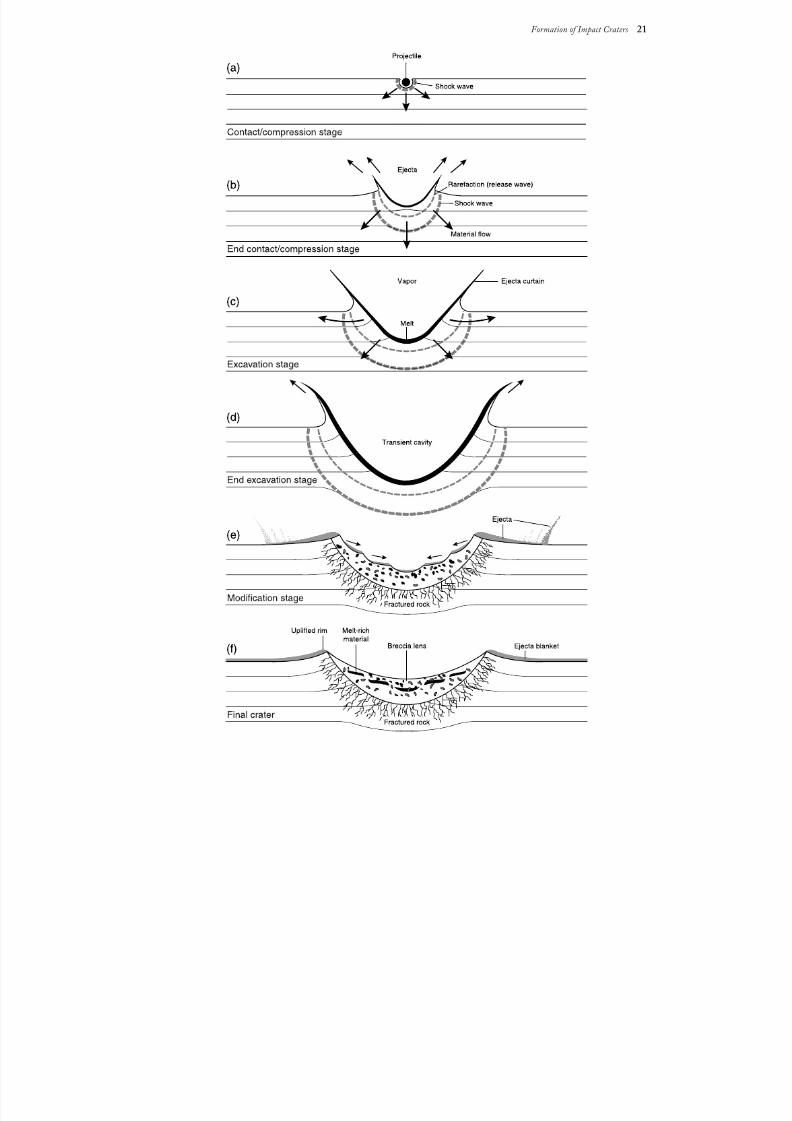
8/8/2019 Traces of Catastrophe - Book
http://slidepdf.com/reader/full/traces-of-catastrophe-book 32/130
Formation of Impact Craters 21
, , ,
, , ,
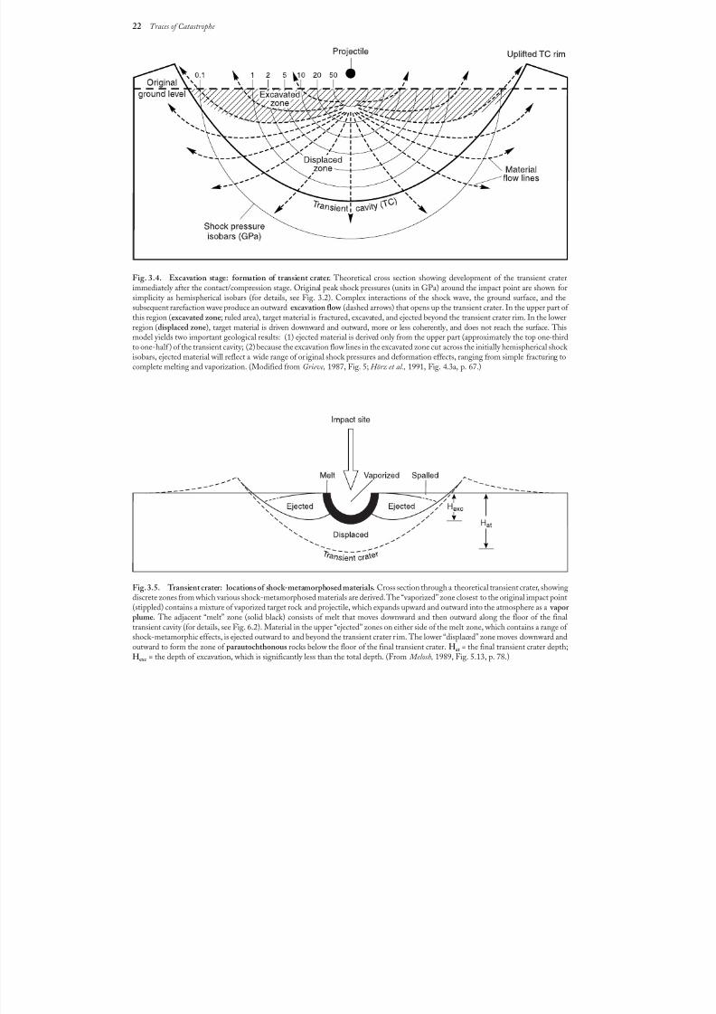
8/8/2019 Traces of Catastrophe - Book
http://slidepdf.com/reader/full/traces-of-catastrophe-book 33/130
22 Traces of Catastrophe
,
,
,
,
,
,
,
,
,
,
Fig. 3.4. Excavation stage: formation of transient crater. Theoretical cross section showing development of the transient craterimmediately after the contact/compression stage. Original peak shock pressures (units in GPa) around the impact point are shown forsimplicity as hemispherical isobars (for details, see Fig. 3.2). Complex interactions of the shock wave, the ground surface, and thesubsequent rarefaction wave produce an outward excavation flow (dashed arrows) that opens up the transient crater. In the upper part of this region (excavated zone; ruled area), target material is fractured, excavated, and ejected beyond the transient crater rim. In the lowerregion (displaced zone), target material is driven downward and outward, more or less coherently, and does not reach the surface. Thismodel yields two important geological results: (1) ejected material is derived only from the upper part (approximately the top one-thirdto one-half ) of the transient cavity; (2) because the excavation flow lines in the excavated zone cut across the initially hemispherical shock isobars, ejected material will reflect a wide range of original shock pressures and deformation effects, ranging from simple fracturing tocomplete melting and vaporization. (Modified from Grieve, 1987, Fig. 5; Hörz et al., 1991, Fig. 4.3a, p. 67.)
Fig. 3.5. Transient crater: locations of shock-metamorphosed materials. Cross section through a theoretical transient crater, showingdiscrete zones from which various shock-metamorphosed materials are derived. The “vaporized” zone closest to the original impact point(stippled) contains a mixture of vaporized target rock and projectile, which expands upward and outward into the atmosphere as a vapor plume. The adjacent “melt” zone (solid black) consists of melt that moves downward and then outward along the floor of the finaltransient cavity (for details, see Fig. 6.2). Material in the upper “ejected” zones on either side of the melt zone, which contains a range of shock-metamorphic effects, is ejected outward to and beyond the transient crater r im. The lower “displaced” zone moves downward andoutward to form the zone of parautochthonous rocks below the floor of the final transient crater. Hat = the final transient crater depth;Hexc = the depth of excavation, which is significantly less than the total depth. (From Melosh, 1989, Fig. 5.13, p. 78.)
, ,
, ,
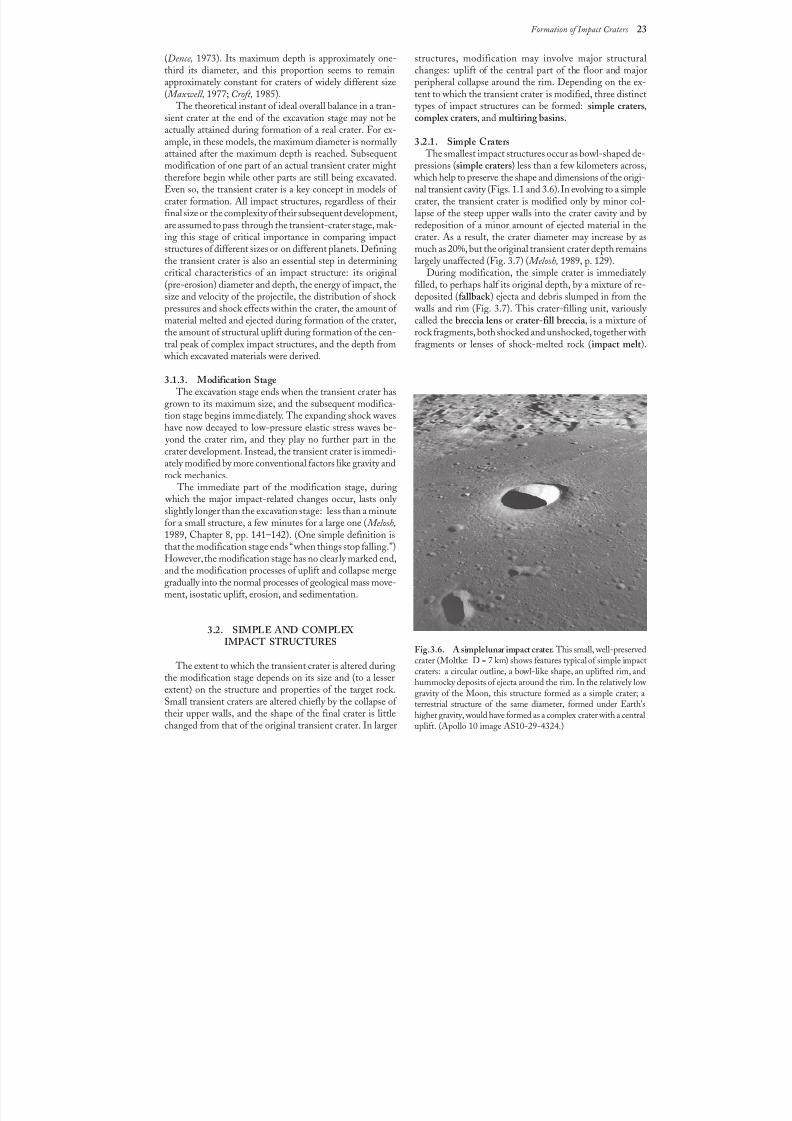
8/8/2019 Traces of Catastrophe - Book
http://slidepdf.com/reader/full/traces-of-catastrophe-book 34/130
Formation of Impact Craters 23
(Dence, 1973). Its maximum depth is approximately one-third its diameter, and this proportion seems to remainapproximately constant for craters of widely different size( Maxwell, 1977; Croft, 1985).
The theoretical instant of ideal overall balance in a tran-sient crater at the end of the excavation stage may not beactually attained during formation of a real crater. For ex-ample, in these models, the maximum diameter is normally
attained after the maximum depth is reached. Subsequentmodification of one part of an actual transient crater mighttherefore begin while other parts are still being excavated.Even so, the transient crater is a key concept in models of crater formation. All impact structures, regardless of theirfinal size or the complexity of their subsequent development,are assumed to pass through the transient-crater stage, mak-ing this stage of critical importance in comparing impactstructures of different sizes or on different planets. Definingthe transient crater is also an essential step in determiningcritical characteristics of an impact structure: its original(pre-erosion) diameter and depth, the energy of impact, thesize and velocity of the projectile, the distribution of shock pressures and shock effects within the crater, the amount of material melted and ejected during formation of the crater,the amount of structural uplift during formation of the cen-tral peak of complex impact structures, and the depth from
which excavated materials were derived.
3.1.3. Modification Stage The excavation stage ends when the transient crater has
grown to its maximum size, and the subsequent modifica-tion stage begins immediately. The expanding shock waveshave now decayed to low-pressure elastic stress waves be-
yond the crater rim, and they play no further part in the
crater development. Instead, the transient crater is immedi-ately modified by more conventional factors like gravity androck mechanics.
The immediate part of the modification stage, during which the major impact-related changes occur, lasts only slightly longer than the excavation stage: less than a minutefor a small structure, a few minutes for a large one ( Melosh,1989, Chapter 8, pp. 141–142). (One simple definition isthat the modification stage ends “when things stop falling.”)However, the modification stage has no clearly marked end,and the modification processes of uplift and collapse mergegradually into the normal processes of geological mass move-ment, isostatic uplift, erosion, and sedimentation.
3.2. SIMPLE AND COMPLEX IMPACT STRUCTURES
The extent to which the transient crater is altered duringthe modification stage depends on its size and (to a lesserextent) on the structure and properties of the target rock.Small transient craters are altered chiefly by the collapse of their upper walls, and the shape of the final crater is littlechanged from that of the original transient crater. In larger
structures, modification may involve major structuralchanges: uplift of the central part of the floor and majorperipheral collapse around the rim. Depending on the ex-tent to which the transient crater is modified, three distincttypes of impact structures can be formed: simple craters,complex craters, and multiring basins.
3.2.1. Simple Craters
The smallest impact structures occur as bowl-shaped de-pressions (simple craters) less than a few kilometers across,
which help to preserve the shape and dimensions of the origi-nal transient cavity (Figs. 1.1 and 3.6). In evolving to a simplecrater, the transient crater is modified only by minor col-lapse of the steep upper walls into the crater cavity and by redeposition of a minor amount of ejected material in thecrater. As a result, the crater diameter may increase by asmuch as 20%, but the original transient crater depth remainslargely unaffected (Fig. 3.7) ( Melosh, 1989, p. 129).
During modification, the simple crater is immediately filled, to perhaps half its original depth, by a mixture of re-deposited (fallback ) ejecta and debris slumped in from the
walls and rim (Fig. 3.7). This crater-filling unit, variously called the breccia lens or crater-fill breccia , is a mixture of rock fragments, both shocked and unshocked, together withfragments or lenses of shock-melted rock (impact melt ).
Fig. 3.6. A simple lunar impact crater.This small, well-preservedcrater (Moltke: D = 7 km) shows features typical of simple impactcraters: a circular outline, a bowl-like shape, an uplifted rim, andhummocky deposits of ejecta around the rim. In the relatively low gravity of the Moon, this structure formed as a simple crater; aterrestrial structure of the same diameter, formed under Earth’shigher gravity, would have formed as a complex crater with a centraluplift. (Apollo 10 image AS10-29-4324.)
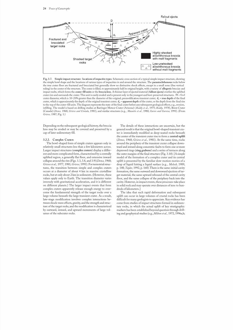
8/8/2019 Traces of Catastrophe - Book
http://slidepdf.com/reader/full/traces-of-catastrophe-book 35/130
24 Traces of Catastrophe
Fig. 3.7. Simple impact structure: locations of impactite types. Schematic cross section of a typical simple impact structure, showingthe simple bowl shape and the locations of various types of impactites in and around the structure. The parautochthonous rocks below the true crater floor are fractured and brecciated but generally show no distinctive shock effects, except in a small zone (fine vertical
ruling) in the center of the structure. The crater is filled, to approximately half its original height, with a variety of allogenic breccias andimpact melts, which forms the crater-fill units or the breccia lens. A thinner layer of ejected material (fallout ejecta ) overlies the upliftedcrater rim and surrounds the crater. This unit is easily eroded and is present only in the youngest and best-preserved structures. D = finalcrater diameter, which is 10–20% greater than the diameter of the original, premodification transient crater; dt = true depth of the finalcrater, which is approximately the depth of the original transient crater; da = apparent depth of the crater, or the depth from the final rimto the top of the crater-fill units. The diagram represents the state of the final crater before any subsequent geological effects, e.g., erosion,infilling. The model is based on drilling studies at Barringer Meteor Crater (Arizona) (Roddy et al., 1975; Roddy, 1978), Brent Crater(Canada) (Dence, 1968; Grieve and Cintala, 1981), and similar structures (e.g., Masaitis et al., 1980; Gurov and Gurova, 1991). (FromGrieve, 1987, Fig. 1.)
Depending on the subsequent geological history, the breccialens may be eroded or may be covered and preserved by a
cap of later sedimentary fill.
3.2.2. Complex Craters The bowl-shaped form of simple craters appears only in
relatively small structures less than a few kilometers across.Larger impact structures (complex craters) display a differ-ent and more complicated form, characterized by a centrally uplifted region, a generally flat floor, and extensive inwardcollapse around the rim (Figs. 1.3, 3.8, and 3.9) (Dence, 1968;Grieve et al., 1977, 1981; Grieve, 1991). For terrestrial struc-tures, the transition between simple and complex cratersoccurs at a diameter of about 4 km in massive crystallinerocks, but at only about 2 km in sediments. (However, these
values apply only to Earth. The transition diameter variesinversely with gravitational acceleration, and it is differenton different planets.) The larger impact events that formcomplex craters apparently release enough energy to over-come the fundamental strength of the target rocks over alarge volume beneath the large transient crater. As a result,late-stage modification involves complex interactions be-tween shock-wave effects, gravity, and the strength and struc-ture of the target rocks, and the modification is characterizedby outward, inward, and upward movements of large vol-umes of the subcrater rocks.
The details of these interactions are uncertain, but thegeneral result is that the original bowl-shaped transient cra-
ter is immediately modified as deep-seated rocks beneaththe center of the transient crater rise to form a central uplift (Dence, 1968; Grieve et al., 1981). At the same time, rocksaround the periphery of the transient crater collapse down-
ward and inward along concentric faults to form one or moredepressed rings (ring grabens) and a series of terraces alongthe outer margins of the final structure (Fig. 3.10). [A simplemodel of the formation of a complex crater and its centraluplift is presented by the familiar slow-motion movies of adrop of liquid hitting a liquid surface (e.g., Melosh, 1989,p. 148; Taylor, 1992, p. 168). There is the same initial cavity formation, the same outward and downward ejection of tar-get material, the same upward rebound of the central cavity
floor, and the same collapse of the periphery back into thecavity. However, in impact events, these processes take placein solid rock and may operate over distances of tens to hun-dreds of kilometers.]
The idea that such rapid deformation and subsequentuplift can occur in large volumes of crustal rocks has beendifficult for many geologists to appreciate. Key evidence hascome from studies of impact structures formed in sedimen-tary rocks, in which the actual uplift of key stratigraphicmarkers has been established beyond question through drill-ing and geophysical studies (e.g., Milton et al., 1972, 1996a,b;
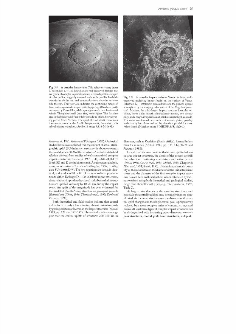
8/8/2019 Traces of Catastrophe - Book
http://slidepdf.com/reader/full/traces-of-catastrophe-book 36/130
Formation of Impact Craters 25
Grieve et al., 1981; Grieve and Pilkington, 1996). Geologicalstudies have also established that the amount of actual strati-graphic uplift (SU) in impact structures is about one-tenththe final diameter (D) of the structure. A detailed statisticalrelation derived from studies of well-constrained compleximpact structures (Grieve et al., 1981, p. 44) is SU = 0.06D1.1
(both SU and D are in kilometers). A subsequent analysis,using more craters (Grieve and Pilkington, 1996, p. 404),gave SU = 0.086 D1.03. The two equations are virtually iden-tical, and a value of SU = 0.1 D is a reasonable approxima-tion to either. For large (D = 100–200 km) impact structures,
these relations imply that the crustal rocks beneath the struc-ture are uplifted vertically by 10–20 km during the impactevent. An uplift of this magnitude has been estimated forthe Vredefort (South Africa) structure on geological grounds(Reimold and Gibson, 1996;Therriault et al., 1997; Turtle and Pierazzo, 1998).
Both theoretical and field studies indicate that centraluplifts form in only a few minutes, almost instantaneously by geological standards, even in the largest structures ( Melosh,1989, pp. 129 and 141–142). Theoretical studies also sug-gest that the central uplifts of structures 200–300 km in
Fig. 3.8. A complex lunar crater. This relatively young crater
(Theophilus: D = 100 km) displays well-preserved features thatare typical of complex impact structures: a central uplift, a scallopedcircular outline, ruggedly terraced walls with possible landslidedeposits inside the rim, and hummocky ejecta deposits just out-side the rim. This view also indicates the continuing nature of lunar cratering; an older impact crater (upper right) has been partly destroyed by Theophilus, while a younger small crater has formed
within Theophilus itself (near rim, lower right). The flat dark area in the background (upper left) is made up of lava flows cover-ing part of Mare Nectaris. The spiral-like rod at left center is aninstrument boom on the Apollo 16 spacecraft, from which thisorbital picture was taken. (Apollo 16 image AS16-M-0692.)
Fig. 3.9. A complex impact basin on Venus. A large, well-preserved multiring impact basin on the surface of Venus(Meitner: D = 150km) is revealed beneath the planet’s opaqueatmosphere by the imaging radar system of the Magellan space-craft. Meitner, the third-largest impact structure identified onVenus, shows a flat smooth (dark-colored) interior, two circularrings, and a rough, irregular blanket of lobate ejecta (light-colored).
The crater was formed on a surface of smooth plains, possibly underlain by lava flows and cut by abundant parallel fractures(white lines). (Magellan image F-MIDRP .55S319;201.)
diameter, such as Vredefort (South Africa), formed in lessthan 15 minutes ( Melosh, 1989, pp. 141–142; Turtle and Pierazzo, 1998).
Despite the extensive evidence that central uplifts do formin large impact structures, the details of the process are stillthe subject of continuing uncertainty and active debate(Dence, 1968; Grieve et al., 1981; Melosh, 1989, Chapter 8;Hörz et al., 1991; Spudis, 1993). Even so fundamental a quan-tity as the ratio between the diameter of the initial transientcrater and the diameter of the final complex impact struc-ture has not been well established; values estimated by vari-
ous workers, using both theoretical and geological studies,range from about 0.5 to 0.7 (see, e.g., Therriault et al., 1997,
Table 2).At larger crater diameters, the resulting structures, and
especially the centrally uplifted area, become even more com-plicated. As the crater size increases the character of the cen-tral uplift changes, and the single central peak is progressively replaced by a more complex series of concentric rings andbasins. At least three types of complex impact structures canbe distinguished with increasing crater diameter: central-peak structures, central-peak-basin structures, and peak-
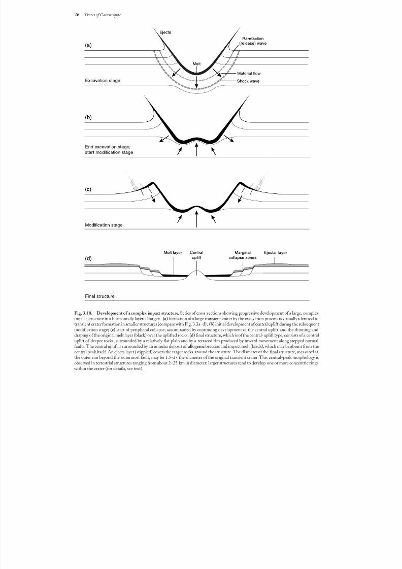
8/8/2019 Traces of Catastrophe - Book
http://slidepdf.com/reader/full/traces-of-catastrophe-book 37/130
26 Traces of Catastrophe
Fig. 3.10. Development of a complex impact structure. Series of cross sections showing progressive development of a large, compleximpact structure in a horizontally layered target: (a) formation of a large transient crater by the excavation process is virtually identical totransient crater formation in smaller structures (compare with Fig. 3.3a–d); (b) initial development of central uplift during the subsequentmodification stage; (c) start of peripheral collapse, accompanied by continuing development of the central uplift and the thinning anddraping of the original melt layer (black) over the uplifted rocks; (d) final structure, which is of the central-uplift type, consists of a centraluplift of deeper rocks, surrounded by a relatively flat plain and by a terraced rim produced by inward movement along stepped normalfaults. The central uplift is surrounded by an annular deposit of allogenic breccias and impact melt (black), which may be absent from thecentral peak itself. An ejecta layer (stippled) covers the target rocks around the structure. The diameter of the final structure, measured atthe outer rim beyond the outermost fault, may be 1.5–2× the diameter of the original transient crater. This central-peak morphology isobserved in terrestrial structures ranging from about 2–25 km in diameter; larger structures tend to develop one or more concentric rings
within the crater (for details, see text).
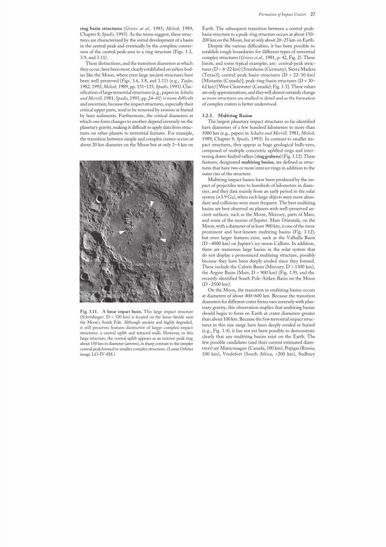
8/8/2019 Traces of Catastrophe - Book
http://slidepdf.com/reader/full/traces-of-catastrophe-book 38/130
Formation of Impact Craters 27
ring basin structures (Grieve at al., 1981; Melosh, 1989,Chapter 8; Spudis, 1993). As the terms suggest, these struc-tures are characterized by the initial development of a basinin the central peak and eventually by the complete conver-sion of the central peak area to a ring structure (Figs. 1.3,3.9, and 3.11).
These distinctions, and the transition diameters at whichthey occur, have been most clearly established on airless bod-
ies like the Moon, where even large ancient structures havebeen well preserved (Figs. 3.6, 3.8, and 3.11) (e.g., Taylor,1982, 1992; Melosh, 1989, pp. 131–135; Spudis, 1993). Clas-sification of large terrestrial structures (e.g., papers in Schultzand Merrill, 1981; Spudis, 1993, pp. 24–41) is more difficultand uncertain, because the impact structures, especially theircritical upper parts, tend to be removed by erosion or buriedby later sediments. Furthermore, the critical diameters at
which one form changes to another depend inversely on theplanetary gravity, making it difficult to apply data from struc-tures on other planets to terrestrial features. For example,the transition between simple and complex craters occurs atabout 20 km diameter on the Moon but at only 2–4 km on
Fig. 3.11. A lunar impact basin. This large impact structure(Schrödinger: D = 320 km) is located on the lunar farside nearthe Moon’s South Pole. Although ancient and highly degraded,it still preserves features distinctive of larger complex impactstructures: a central uplift and terraced walls. However, in thislarge structure, the central uplift appears as an interior peak ringabout 150 km in diameter (arrows), in sharp contrast to the simplercentral peak formed in smaller complex structures. (Lunar Orbiterimage LO-IV-8M.)
Earth. The subsequent transition between a central-peak-basin structure to a peak-ring structure occurs at about 150–200 km on the Moon, but at only about 20–25 km on Earth.
Despite the various difficulties, it has been possible toestablish rough boundaries for different types of terrestrialcomplex structures (Grieve et al., 1981, p. 42, Fig. 2). Theselimits, and some typical examples, are: central-peak struc-tures (D = 4–22 km) [Steinheim (Germany), Sierra Madera
(Texas)]; central-peak-basin structures (D = 22–30 km)[Mistastin (Canada)]; peak-ring-basin structures (D = 30–62 km) [West Clearwater (Canada); Fig. 1.3]. These valuesare only approximations, and they will almost certainly changeas more structures are studied in detail and as the formationof complex craters is better understood.
3.2.3. Multiring Basins The largest planetary impact structures so far identified
have diameters of a few hundred kilometers to more than1000 km (e.g., papers in Schultz and Merrill, 1981; Melosh,1989, Chapter 9; Spudis, 1993). In contrast to smaller im-pact structures, they appear as huge geological bulls-eyes,composed of multiple concentric uplifted rings and inter-
vening down-faulted valleys (ring grabens) (Fig. 3.12). Thesefeatures, designated multiring basins, are defined as struc-tures that have two or more interior rings in addition to theouter rim of the structure.
Multiring impact basins have been produced by the im-pact of projectiles tens to hundreds of kilometers in diam-eter, and they date mainly from an early period in the solarsystem (>3.9 Ga), when such large objects were more abun-dant and collisions were more frequent. The best multiringbasins are best observed on planets with well-preserved an-cient surfaces, such as the Moon, Mercury, parts of Mars,
and some of the moons of Jupiter. Mare Orientale, on theMoon, with a diameter of at least 900 km, is one of the mostprominent and best-known multiring basins (Fig. 3.12),but even larger features exist, such as the Valhalla Basin(D ~4000km) on Jupiter’s icy moon Callisto. In addition,there are numerous large basins in the solar system thatdo not display a pronounced multiring structure, possibly because they have been deeply eroded since they formed.
These include the Caloris Basin (Mercury; D = 1300 km),the Argyre Basin (Mars; D > 900 km) (Fig. 1.9), and therecently identified South Pole-Aitken Basin on the Moon(D ~2500 km).
On the Moon, the transition to multiring basins occurs
at diameters of about 400–600 km. Because the transitiondiameters for different crater forms vary inversely with plan-etary gravity, this observation implies that multiring basinsshould begin to form on Earth at crater diameters greaterthan about 100 km. Because the few terrestrial impact struc-tures in this size range have been deeply eroded or buried(e.g., Fig. 1.4), it has not yet been possible to demonstrateclearly that any multiring basins exist on the Earth. Thefew possible candidates (and their current estimated diam-eters) are Manicouagan (Canada, 100 km), Popigai (Russia,100 km), Vredefort (South Africa, >200 km), Sudbury
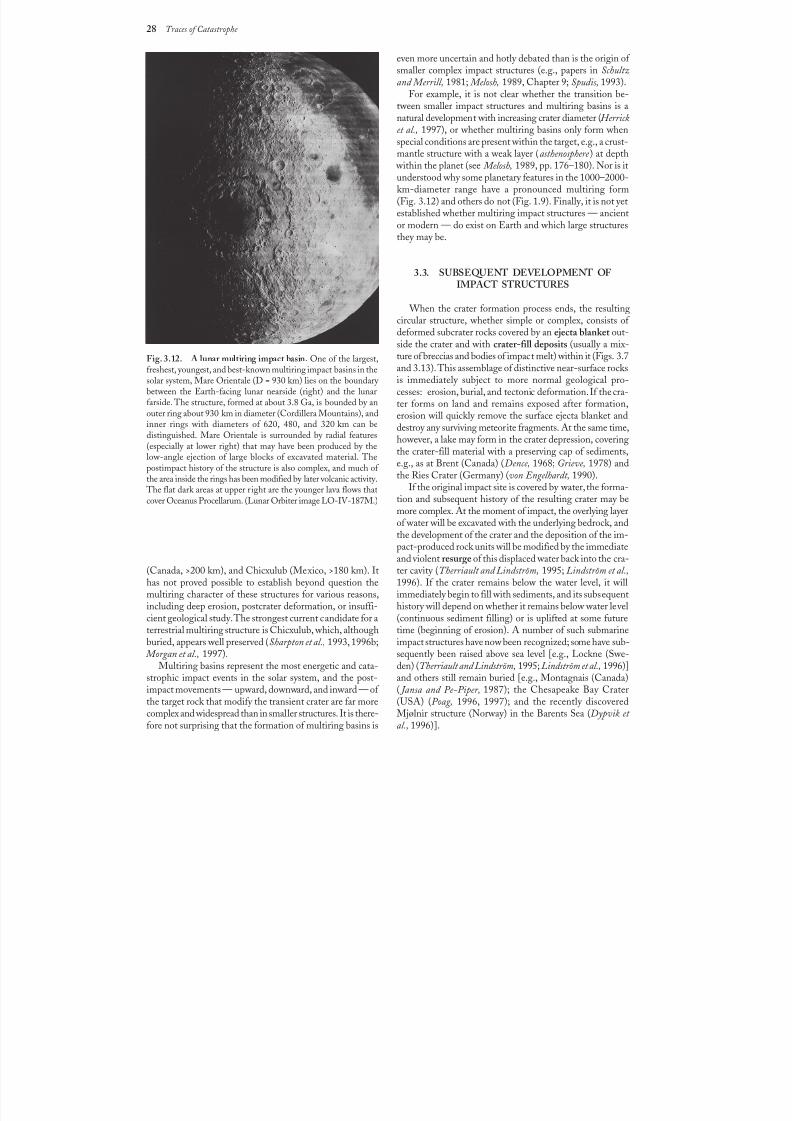
8/8/2019 Traces of Catastrophe - Book
http://slidepdf.com/reader/full/traces-of-catastrophe-book 39/130
28 Traces of Catastrophe
Fig. 3.12. A lunar multiring impact basin. One of the largest,freshest, youngest, and best-known multiring impact basins in thesolar system, Mare Orientale (D= 930 km) lies on the boundary between the Earth-facing lunar nearside (right) and the lunarfarside. The structure, formed at about 3.8 Ga, is bounded by anouter ring about 930 km in diameter (Cordillera Mountains), andinner rings with diameters of 620, 480, and 320km can bedistinguished. Mare Orientale is surrounded by radial features(especially at lower right) that may have been produced by the
low-angle ejection of large blocks of excavated material. Thepostimpact history of the structure is also complex, and much of the area inside the rings has been modified by later volcanic activity.
The flat dark areas at upper r ight are the younger lava flows thatcover Oceanus Procellarum. (Lunar Orbiter image LO-IV-187M.)
(Canada, >200 km), and Chicxulub (Mexico, >180 km). Ithas not proved possible to establish beyond question themultiring character of these structures for various reasons,
including deep erosion, postcrater deformation, or insuffi-cient geological study. The strongest current candidate for aterrestrial multiring structure is Chicxulub, which, althoughburied, appears well preserved (Sharpton et al., 1993, 1996b; Morgan et al., 1997).
Multiring basins represent the most energetic and cata-strophic impact events in the solar system, and the post-impact movements — upward, downward, and inward — of the target rock that modify the transient crater are far morecomplex and widespread than in smaller structures. It is there-fore not surprising that the formation of multiring basins is
even more uncertain and hotly debated than is the origin of smaller complex impact structures (e.g., papers in Schultzand Merrill, 1981; Melosh, 1989, Chapter 9; Spudis, 1993).
For example, it is not clear whether the transition be-tween smaller impact structures and multiring basins is anatural development with increasing crater diameter (Herricket al., 1997), or whether multiring basins only form whenspecial conditions are present within the target, e.g., a crust-
mantle structure with a weak layer (asthenosphere ) at depth within the planet (see Melosh, 1989, pp. 176–180). Nor is itunderstood why some planetary features in the 1000–2000-km-diameter range have a pronounced multiring form(Fig.3.12) and others do not (Fig. 1.9). Finally, it is not yetestablished whether multiring impact structures — ancientor modern — do exist on Earth and which large structuresthey may be.
3.3. SUBSEQUENT DEVELOPMENT OFIMPACT STRUCTURES
When the crater formation process ends, the resultingcircular structure, whether simple or complex, consists of deformed subcrater rocks covered by an ejecta blanket out-side the crater and with crater-fill deposits (usually a mix-ture of breccias and bodies of impact melt) within it (Figs.3.7and 3.13). This assemblage of distinctive near-surface rocksis immediately subject to more normal geological pro-cesses: erosion, burial, and tectonic deformation. If the cra-ter forms on land and remains exposed after formation,erosion will quickly remove the surface ejecta blanket anddestroy any surviving meteorite fragments. At the same time,however, a lake may form in the crater depression, covering
the crater-fill material with a preserving cap of sediments,e.g., as at Brent (Canada) (Dence, 1968; Grieve, 1978) andthe Ries Crater (Germany) (von Engelhardt, 1990).
If the original impact site is covered by water, the forma-tion and subsequent history of the resulting crater may bemore complex. At the moment of impact, the overlying layerof water will be excavated with the underlying bedrock, andthe development of the crater and the deposition of the im-pact-produced rock units will be modified by the immediateand violent resurge of this displaced water back into the cra-ter cavity (Therriault and Lindström, 1995; Lindström et al.,1996). If the crater remains below the water level, it willimmediately begin to fill with sediments, and its subsequent
history will depend on whether it remains below water level(continuous sediment filling) or is uplifted at some futuretime (beginning of erosion). A number of such submarineimpact structures have now been recognized; some have sub-sequently been raised above sea level [e.g., Lockne (Swe-den) (Therriault and Lindström, 1995; Lindström et al., 1996)]and others still remain buried [e.g., Montagnais (Canada)( Jansa and Pe-Piper, 1987); the Chesapeake Bay Crater(USA) (Poag, 1996, 1997); and the recently discoveredMjølnir structure (Norway) in the Barents Sea (Dypvik et al., 1996)].
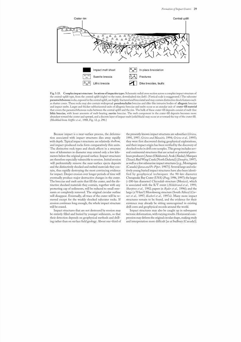
8/8/2019 Traces of Catastrophe - Book
http://slidepdf.com/reader/full/traces-of-catastrophe-book 40/130
Formation of Impact Craters 29
Fig. 3.13. Complex impact structure: locations of impactite types. Schematic radial cross section across a complex impact structure of the central-uplift type, from the central uplift (right) to the outer, downfaulted rim (left). (Vertical scale is exaggerated.) The subcraterparautochthonous rocks, exposed in the central uplift, are highly fractured and brecciated and may contain distinctive shock features suchas shatter cones. These rocks may also contain widespread pseudotachylite breccias and dike-like intrusive bodies of allogenic brecciasand impact melts. Larger and thicker subhorizontal units of allogenic breccias and melts occur as an annular unit of crater-fill material that covers the parautochthonous rocks between the central uplift and the rim. The bulk of these crater-fill deposits consist of melt-freelithic breccias, with lesser amounts of melt-bearing suevite breccias. The melt component in the crater-fill deposits becomes moreabundant toward the center and upward, and a discrete layer of impact melt (solid black) may occur at or toward the top of the crater fill.(Modified from Stöffler et al., 1988, Fig. 12, p. 290.)
Because impact is a near-surface process, the deforma-
tion associated with impact structures dies away rapidly with depth. Typical impact structures are relatively shallow,and impact-produced rocks form comparatively thin units.
The distinctive rock types and shock effects in a structuretens of kilometers in diameter may extend only a few kilo-meters below the original ground surface. Impact structuresare therefore especially vulnerable to erosion. Initial erosion
will preferentially remove the near-surface ejecta depositsand the distinctively shocked and melted materials they con-tain, thus rapidly destroying the most convincing evidencefor impact. Deeper erosion over longer periods of time willeventually produce major destructive changes in the crater.
The breccias and melt units that fill the crater, and the dis-
tinctive shocked materials they contain, together with any protecting cap of sediments, will be reduced to small rem-nants or completely removed. The original circular outline
will disappear. Eventually, all trace of the crater will be re-moved except for the weakly shocked subcrater rocks. If erosion continues long enough, the whole impact structure
will be erased.Impact structures that are not destroyed by erosion may
be entirely filled and buried by younger sediments, so thattheir detection depends on geophysical methods and drill-ing rather than on surface field geology. About one-third of
the presently known impact structures are subsurface (Grieve,
1991, 1997; Grieve and Masaitis, 1994; Grieve et al., 1995);they were first discovered during geophysical explorations,and their impact origin has been verified by the discovery of shocked rocks in drill core samples. This group includes sev-eral continental structures that are actual or potential petro-leum producers [Ames (Oklahoma); Avak (Alaska); Marquez (Texas); Red Wing Creek (North Dakota)] (Donofrio, 1997),as well as a few submarine impact structures [e.g., Montagnais(Canada) ( Jansa and Pe-Piper, 1987)]. Several large and rela-tively young buried impact structures have also been identi-fied by geophysical techniques: the 90-km-diameterChesapeake Bay Crater (USA) (Poag, 1996, 1997); the larger(>180-km diameter) Chicxulub structure (Mexico), which
is associated with the K/T event (Hildebrand et al., 1991;Sharpton et al., 1992; papers in Ryder et al., 1996); and thelarge (>70 km?) Morokweng structure (South Africa) (Cor-ner et al., 1997; Koeberl et al., 1997a). Many more impactstructures remain to be found, and the evidence for theirexistence may already be sitting unrecognized in existingdrill cores and geophysical records around the world.
Impact structures may also be caught up in subsequenttectonic deformation, with varying results. Horizontal com-pression may deform the original circular shape, making study and interpretation more difficult [as at Sudbury (Canada)].

8/8/2019 Traces of Catastrophe - Book
http://slidepdf.com/reader/full/traces-of-catastrophe-book 41/130
30 Traces of Catastrophe
Tectonism can also break up regions of original shocked rocksand disperse them as large discrete areas across the geo-logical landscape [e.g., the Beaverhead (Idaho) structure(Hargraves et al., 1990; Fiske et al., 1994)]. Sufficient tec-tonism and metamorphism could destroy even large impactstructures or make them totally unrecognizable.
Geologists must therefore be prepared to recognize im-pact structures in all states of preservation, from young, fresh,
well-exposed circular structures filled with distinctive shocked
breccias to older features in which distinctive shock effectsare scattered, barely recognizable, or deeply buried. It is es-sential to be able to recognize the variety of distinctive shock effects associated with impact structures and to understand
where different types of shock effects may be located in theoriginal crater.
8/8/2019 Traces of Catastrophe - Book
http://slidepdf.com/reader/full/traces-of-catastrophe-book 42/130
Shock-Metamorphic Effects in Rocks and Minerals 31
31
4.1. FORMATION CONDITIONS ANDGENERAL CHARACTERISTICS
The growing recognition since the 1960s of the geologi-cal importance of meteorite impact events, and the largenumber of impact structures still preserved on Earth, is largely the result of two related discoveries: (1) The extreme physi-cal conditions that are imposed by intense shock waves onthe rocks through which they pass produce unique, recog-nizable, and durable shock-metamorphic effects; (2) suchshock waves are produced naturally only by the hypervelocity
impacts of extraterrestrial objects (French, 1968a, 1990b;French and Short, 1968). Shock-metamorphic effects (alsocalled “shock effects” or “shock features”) have been criticalto the identification of terrestrial impact structures becauseof their uniqueness, wide distribution, ease of identification,and especially their ability to survive over long periods of geologic time.
With the acceptance of shock effects as a criterion forimpact, the record of terrestrial impact events is no longerlimited to small young structures that still preserve definitemeteorite fragments. Equally convincing evidence for im-pact can now be provided by a wide variety of distinctivedeformation effects in the rocks themselves, and it has be-
come possible to identify numerous old impact structuresfrom which weathering and erosion have removed all physi-cal traces of the projectiles that formed them. The recogni-tion of preserved shock effects has been the main factorbehind the steady increase in the number of recognized im-pact structures since the 1960s (Grieve, 1991; Grieve et al.,1995; Grieve and Pesonen,1992, 1996; for historical reviews,see Hoyt, 1987; Mark, 1987).
The approximate physical conditions that produce shock-deformation effects in natural rocks have been establishedby a combination of theoretical studies, artificial explosions
(both chemical and nuclear), and experiments with labora-tory shock-wave devices (for details, see papers in Frenchand Short, 1968 and Roddy et al., 1977; also Stöffler, 1972;Kieffer and Simonds, 1980; Melosh, 1989; Stöffler and Langenhorst, 1994). Peak shock pressures produced in animpact event range from >2 GPa ( >20 kbar) near the finalcrater rim to >100 GPa (>1000 kbar) near the impact point.
These pressures, and the resulting shock-deformation ef-fects, reflect conditions that are far outside the range of nor-mal geological processes (Fig. 4.1, Table 4.1). In ordinary geological environments, pressures equivalent to those of
typical shock waves are attained only under static conditionsat depths of 75–1000 km within Earth, well below the shal-low-crustal regions in which impact structures are formed.
Shock-wave pressures differ in other important ways frompressures produced by more normal geological processes. Theapplication of shock-wave pressures is both sudden and brief.A shock wave traveling at several kilometers per second willtraverse the volume of a mineral grain or a rock sample inmicroseconds, and both the onset and release of pressure arehighly transient. Shock-deformation effects therefore reflecttransient stress conditions, high strain rates, and rapidquenching that are inconsistent with the rates of normalgeological processes (Table 4.1). In addition, shock waves
deposit energy in the materials through which they pass. Aparticular shock pressure will produce a specific postshock temperature, which depends chiefly on the nature of the tar-get material. These postshock temperatures increase with in-creasing shock pressure (see the P-T curve labeled “Shock metamorphism” in Fig. 4.1). For large shock pressures, theresulting temperatures are high enough to produce meltingand even vaporization within the target.
The unique conditions of shock-wave environments pro-duce unique effects in the affected rocks. The nature andintensity of the changes depend on the shock pressures
Shock-Metamorphic Effects inRocks and Minerals
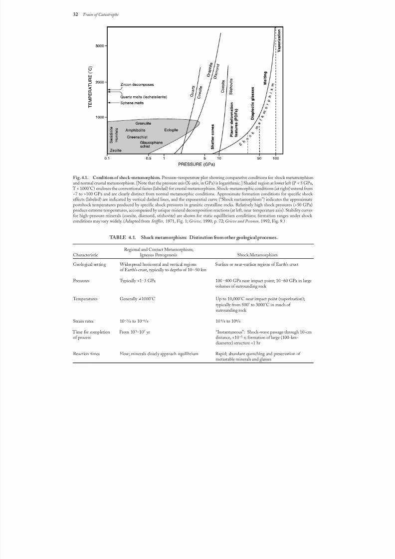
8/8/2019 Traces of Catastrophe - Book
http://slidepdf.com/reader/full/traces-of-catastrophe-book 43/130
32 Traces of Catastrophe
Fig. 4.1. Conditions of shock-metamorphism. Pressure-temperature plot showing comparative conditions for shock metamorphismand normal crustal metamorphism. [Note that the pressure axis (X-axis, in GPa) is logarithmic.] Shaded region at lower left (P < 5 GPa,
T < 1000°C) encloses the conventional facies (labeled) for crustal metamorphism. Shock-metamorphic conditions (at right) extend from~7 to >100 GPa and are clearly distinct from normal metamorphic conditions. Approximate formation conditions for specific shock effects (labeled) are indicated by vertical dashed lines, and the exponential curve (“Shock metamorphism”) indicates the approximatepostshock temperatures produced by specific shock pressures in granitic crystalline rocks. Relatively high shock pressures (>50 GPa)produce extreme temperatures, accompanied by unique mineral decomposition reactions (at left, near temperature axis). Stability curvesfor high-pressure minerals (coesite, diamond, stishovite) are shown for static equilibrium conditions; formation ranges under shock conditions may vary widely. (Adapted from Stöffler, 1971, Fig. 1; Grieve, 1990, p. 72; Grieve and Pesonen, 1992, Fig. 9.)
TABLE 4.1. Shock metamorphism: Distinction from other geological processes.
Regional and Contact Metamorphism;Characteristic Igneous Petrogenesis Shock Metamorphism
Geological setting Widespread horizontal and vertical regions Surface or near-surface regions of Earth’s crustof Earth’s crust, typically to depths of 10 –50 km
Pressures Typically <1–3 GPa 100–400 GPa near impact point; 10–60 GPa in large volumes of surrounding rock
Temperatures Generally >1000°C Up to 10,000°C near impact point (vaporization);
typically from 500° to 3000°C in much of surrounding rock
Strain rates 10–3/s to 10–6/s 104/s to 106/s
Time for completion From 10 5–107 yr “Instantaneous”: Shock-wave passage through 10-cmof process distance, <10–5 s; formation of large (100-km-
diameter) structure <1 hr
Reaction times Slow; minerals closely approach equilibrium Rapid; abundant quenching and preservation of metastable minerals and glasses
8/8/2019 Traces of Catastrophe - Book
http://slidepdf.com/reader/full/traces-of-catastrophe-book 44/130
Shock-Metamorphic Effects in Rocks and Minerals 33
(Table4.2). Lower shock pressures (~2–10 GPa) producedistinctive megascopic shatter cones in the target rocks( Milton, 1977; Roddy and Davis, 1977). Higher pressures(>10–45 GPa) produce distinctive high-pressure mineralpolymorphs as well as unusual microscopic deformation fea-tures in such minerals as quartz and feldspar (Stöffler, 1972).Even higher pressures (>50 GPa) produce partial to com-plete melting and even vaporization (>100 GPa) of large
volumes of the target rocks.An especially distinctive and convincing form of evidence
for meteorite impact is the suite of unique microscopic de-
formation features produced within individual minerals by higher-pressure (~10–45 GPa) shock waves. During theimpact event, such pressures develop in target rocks near thecenter of the crater, and most of these rocks are immediately broken up and incorporated into the excavation flow that isbeing initiated by the expanding release wave (Figs. 3.4 and3.5). As a result, these shock effects are found chiefly in in-dividual target rock fragments in the breccias that fill thecrater or in the ejecta deposited beyond the rim.
A wide variety of shock-produced microscopic deforma-tion features has been identified in the minerals of shock-
metamorphosed rocks (for reviews, see Chao, 1967; papersin French and Short, 1968; Stöffler, 1972, 1974; Stöffler and Langenhorst, 1994; Grieve et al., 1996). These include(1) kink bands in micas and (more rarely) in olivine andpyroxene; (2) several types of distinctive planar microstruc-tures and related deformation effects in quartz, feldspar, andother minerals; (3) isotropic mineral glasses (diaplectic orthetomorphic glasses) produced selectively, most commonly from quartz and feldspar, without actual melting; (4) selec-tive melting of individual minerals. Kink bands, althoughcommon in impact environments (Fig. 4.2), can also be pro-
duced by normal tectonic deformation; they are not a uniquecriterion for shock metamorphism, and they will not be dis-cussed further. The other effects, particularly the distinctiveplanar microstructures in quartz and the diaplectic glasses,are now generally accepted as unique criteria for shock wavesand meteorite impact events.
These shock-produced microscopic deformation featureshave several distinctive general characteristics. They are pervasive , and usually occur throughout a centimeter-sizedrock sample, although they may be more erratically devel-oped over larger distances (meters or tens of meters). They
TABLE 4.2. Shock pressures and effects.
Approximate EstimatedShock Pressure Postshock Effects
(GPa) Temperature (°C)*
2–6 <100 Rock fracturing; breccia formation
Shatter cones
5–7 100 Mineral fracturing: (0001) and {1011}in quartz
8–10 100 Basal Brazil twins (0001)
10 100*
Quartz with PDFs {1013}
12–15 150 Quartz → stishovite
13 150 Graphite → cubic diamond
20 170*
Quartz with PDFs {1012}, etc.Quartz, feldspar with reduced refractive
indexes, lowered birefringence
>30 275 Quartz → coesite
35 300
Diaplectic quartz, feldspar glasses
45 900 Normal (melted) feldspar glass (vesiculated)
60 >1500 Rock glasses, crystallized melt rocks (quenchedfrom liquids)
80–100 >2500 Rock glasses (condensed from vapor)
* For dense nonporous rocks. For porous rocks (e.g., sandstones), postshock temperatures = 700°C(P = 10 GPa) and 1560°C (P = 20 GPa). Data from Stöffler (1984), Table 3; Melosh (1989),
Table 3.2; Stöffler and Langenhorst (1994), Table 8, p. 175.
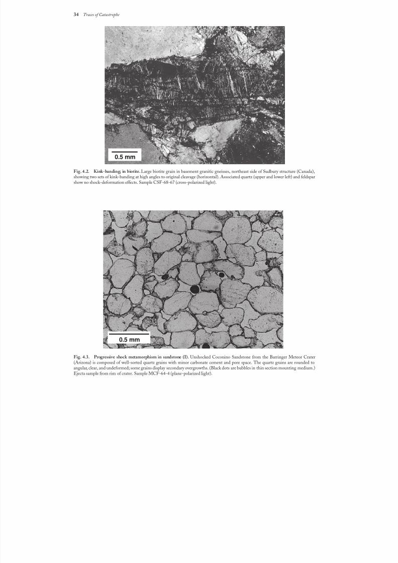
8/8/2019 Traces of Catastrophe - Book
http://slidepdf.com/reader/full/traces-of-catastrophe-book 45/130
34 Traces of Catastrophe
Fig. 4.2. Kink-banding; in biotite. Large biotite grain in basement granitic gneisses, northeast side of Sudbury structure (Canada),showing two sets of kink-banding at high angles to original cleavage (horizontal). Associated quartz (upper and lower left) and feldsparshow no shock-deformation effects. Sample CSF-68-67 (cross-polarized light).
Fig. 4.3. Progressive shock metamorphism in sandstone (I). Unshocked Coconino Sandstone from the Barringer Meteor Crater(Arizona) is composed of well-sorted quartz grains with minor carbonate cement and pore space. The quartz grains are rounded toangular, clear, and undeformed; some grains display secondary overgrowths. (Black dots are bubbles in thin section mounting medium.)Ejecta sample from rim of crater. Sample MCF-64-4 (plane-polarized light).
0.5 mm
0.5 mm
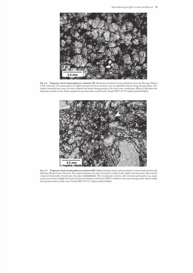
8/8/2019 Traces of Catastrophe - Book
http://slidepdf.com/reader/full/traces-of-catastrophe-book 46/130
Shock-Metamorphic Effects in Rocks and Minerals 35
Fig. 4.4. Progressive shock metamorphism in sandstone (II). Moderately shocked Coconino Sandstone from the Barringer MeteorCrater (Arizona). The quartz grains are highly fractured and show numerous sets of subparallel fractures along cleavage planes. Theoriginal interstitial pore space has been collapsed and heated during passing of the shock wave, producing a filling of dark glass thatfrequently contains coesite. Ejecta sample from ground surface outside crater. Sample MCF-65-15-4 (plane-polarized light).
Fig.4.5. Progressive shock metamorphism in sandstone (III). Highly shocked, melted, and vesiculated Coconino Sandstone from theBarringer Meteor Crater (Arizona). The original sandstone has been converted to a light, frothy, highly vesicular pumice-like materialcomposed dominantly of nearly pure silica glass (lechatelierite). The vesicular glass contains a few remnant quartz grains (e.g., uppercenter, arrow) that are highly fractured and show development of distinctive PDFs in addition to the open cleavage cracks. Ejecta samplefrom ground surface outside crater. Sample MCF-65-11-2 (plane-polarized light).
0.5 mm
0.5 mm
8/8/2019 Traces of Catastrophe - Book
http://slidepdf.com/reader/full/traces-of-catastrophe-book 47/130
36 Traces of Catastrophe
are mineralogically selective ; a given effect (e.g., isotropiza-tion) will occur in grains of a single mineral (e.g., quartz orfeldspar), but not in grains of other minerals, even adjacentones. Shock metamorphism is also characterized by a pro- gressive destruction of original textures with increasing shock pressure, a process that eventually leads to complete meltingor vaporization of the target rock (Figs. 4.3, 4.4, and 4.5).
4.2. STAGES OF SHOCK METAMORPHISM
The fact that different shock pressures produce a variety of distinctive shock features (Table 4.2) has made it possibleto recognize different levels or stages of shock metamor-phism (Chao, 1967; Stöffler, 1966, 1971, 1984; von Engelhardt and Stöffler, 1968; Stöffler and Langenhorst, 1994). These stagesare not equivalent to the different facies recognized in nor-mal metamorphism, because shock metamorphism is a rapidand nonequilibrium process and many of the most distinc-tive features produced by shock waves (e.g., high-pressureminerals and diaplectic glasses) are metastable under nor-mal geological conditions. Nevertheless, key shock featuresoccur frequently and consistently in natural impact struc-tures, and the production of the same features in experimen-tal studies has made approximate pressure and temperaturecalibrations possible. As a result, the stages of shock meta-morphism have become an important concept for field studiesof impact structures and for using certain features as ap-proximate shock-wave barometers.
Current classifications of shock-metamorphic stages arebased almost entirely on features developed in nonporous,quartz-bearing, crystalline igneous and metamorphic rocks.
These lithologies are abundant in many of the impact struc-
tures studied so far, and they develop a varied suite of shock features over a wide range of shock pressures. Individual clas-sifications of shock-metamorphic stages in these rocks dif-fer in details, but the following summary of distinctive shock features and their approximate shock pressures (based largely on Stöffler, 1966, 1971, 1984; Stöffler and Langenhorst, 1994)provides a useful classification based on field and petrographiccharacteristics. [Other effects observed with increasing shock pressure include decreases in refractive index and increasingstructural disorder (shock mosaicism) in mineral grains; fordetails, see Stöffler, 1972, 1974; Stöffler and Langenhorst,1994).] It should be remembered that estimated pressuresare only approximate, and that the formation of a given shock
effect will also reflect such individual factors as rock type,grain size, and other structural features. The shock effectsobserved, and the inferred stages of shock metamorphism,
will be different for other rock types, especially for carbon-ates, basaltic rocks, and porous rocks of any type.
For nonporous crystalline rocks, the following stages havebeen distinguished (see Table 4.2):
<2 GPa Fracturing and brecciation, without development of
unique shock features (see Chapter 5).
>2 GPa to <30? GPa Shatter cones. At lower pressures (2 to <10 GPa), occur-
ring without distinctive microscopic deformation features.At higher pressures (10 to >30 GPa), shatter cones may alsocontain distinctive microdeformation features.
~8 GPa to 25 GPa Microscopic planar deformation features in individual
minerals, especially quartz and feldspar. It has been possibleto subdivide this zone on the basis of different fabrics of deformation features in quartz (Robertson et al., 1968; Stöffler and Langenhorst, 1994).
>25 GPa to 40 GPa Transformation of individual minerals to amorphous
phases (diaplectic glasses) without melting. These glassesare often accompanied by the formation of high-pressuremineral polymorphs.
>35 GPa to 60 GPa Selective partial melting of individual minerals, typically
feldspars. Increasing destruction of original textures.
>60 GPa to 100 GPa Complete melting of all minerals to form a superheated
rock melt (see Chapter 6).
>100 GPa Complete rock vaporization. No preserved materials
formed at this stage (e.g., by vaporization and subsequentcondensation to glassy materials) have been definitely iden-tified so far.
4.3. MEGASCOPIC SHOCK-DEFORMATIONFEATURES: SHATTER CONES
Shatter cones are the only distinctive and unique shock-deformation feature that develops on a megascopic (handspecimen to outcrop) scale. Most accepted shock-metamor-phic features are microscopic deformations produced at rela-tively high shock pressures (>10 GPa). Lower shock pressures(1–5 GPa) produce a variety of unusual fractured and brec-ciated rocks, but such rocks are so similar to rocks formed by normal tectonic or volcanic processes that their presence can-not be used as definite evidence for an impact event. How-
ever, such low shock pressures also generate distinctive conicalfracturing patterns in the target rocks, and the resulting shat-ter cones have proven to be a reliable field criterion for iden-tifying and studying impact structures (Dietz, 1947, 1959,1963, 1968; Milton et al., 1972, 1996a; Roddy and Davis,1977; Sharpton et al., 1996a; Dressler and Sharpton, 1997).
Shatter cones are distinctive curved, striated fractures thattypically form partial to complete cones (Figs. 4.6 and 4.7).
They are generally found in place in the rocks below thecrater floor, usually in the central uplifts of complex impactstructures, but they are also rarely observed in isolated rock
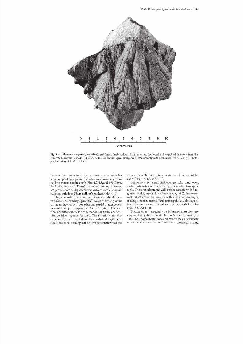
8/8/2019 Traces of Catastrophe - Book
http://slidepdf.com/reader/full/traces-of-catastrophe-book 48/130
Shock-Metamorphic Effects in Rocks and Minerals 37
Fig. 4.6. Shatter cones; small, well-developed. Small, finely sculptured shatter cones, developed in fine-grained limestone from theHaughton structure (Canada). The cone surfaces show the typical divergence of striae away from the cone apex (“horsetailing”). Photo-graph courtesy of R. A. F. Grieve.
fragments in breccia units. Shatter cones occur as individu-als or composite groups, and individual cones may range frommillimeters to meters in length (Figs. 4.7, 4.8, and 4.9) (Dietz,
1968; Sharpton et al., 1996a). Far more common, however,are partial cones or slightly curved surfaces withdistinctiveradiating striations (“horsetailing ”) on them (Fig.4.10).
The details of shatter cone morphology are also distinc-tive. Smaller secondary (“parasitic”) cones commonly occuron the surfaces of both complete and partial shatter cones,forming a unique composite or “nested” texture. The sur-faces of shatter cones, and the striations on them, are defi-nite positive/negative features. The striations are alsodirectional; they appear to branch and radiate along the sur-face of the cone, forming a distinctive pattern in which the
acute angle of the intersection points toward the apex of thecone (Figs. 4.6, 4.8, and 4.10).
Shatter cones form in all kinds of target rocks: sandstones,
shales, carbonates, and crystalline igneous and metamorphicrocks. The most delicate and well-formed cones form in fine-grained rocks, especially carbonates (Fig. 4.6). In coarserrocks, shatter cones are cruder, and their striations are larger,making the cones more difficult to recognize and distinguishfrom nonshock deformational features such as slickensides(Figs. 4.8 and 4.10).
Shatter cones, especially well-formed examples, areeasy to distinguish from similar nonimpact features (see
Table4.3). Some shatter cone occurrences may superficially resemble the “cone-in-cone” structures produced during
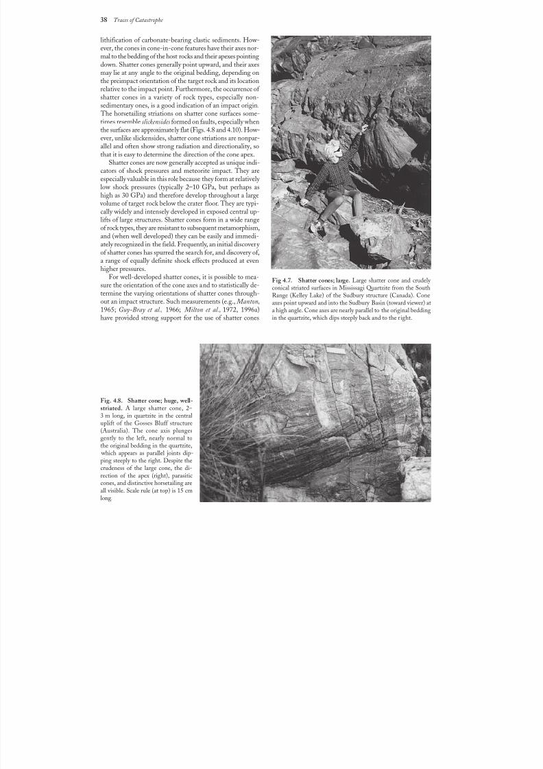
8/8/2019 Traces of Catastrophe - Book
http://slidepdf.com/reader/full/traces-of-catastrophe-book 49/130
38 Traces of Catastrophe
lithification of carbonate-bearing clastic sediments. How-ever, the cones in cone-in-cone features have their axes nor-mal to the bedding of the host rocks and their apexes pointingdown. Shatter cones generally point upward, and their axesmay lie at any angle to the original bedding, depending onthe preimpact orientation of the target rock and its locationrelative to the impact point. Furthermore, the occurrence of shatter cones in a variety of rock types, especially non-
sedimentary ones, is a good indication of an impact origin. The horsetailing striations on shatter cone surfaces some-times resemble slickensides formed on faults, especially whenthe surfaces are approximately flat (Figs. 4.8 and 4.10). How-ever, unlike slickensides, shatter cone striations are nonpar-allel and often show strong radiation and directionality, sothat it is easy to determine the direction of the cone apex.
Shatter cones are now generally accepted as unique indi-cators of shock pressures and meteorite impact. They areespecially valuable in this role because they form at relatively low shock pressures (typically 2–10 GPa, but perhaps ashigh as 30 GPa) and therefore develop throughout a large
volume of target rock below the crater floor. They are typi-cally widely and intensely developed in exposed central up-lifts of large structures. Shatter cones form in a wide rangeof rock types, they are resistant to subsequent metamorphism,and (when well developed) they can be easily and immedi-ately recognized in the field. Frequently, an initial discovery of shatter cones has spurred the search for, and discovery of,a range of equally definite shock effects produced at evenhigher pressures.
For well-developed shatter cones, it is possible to mea-sure the orientation of the cone axes and to statistically de-termine the varying orientations of shatter cones through-out an impact structure. Such measurements (e.g., Manton,
1965; Guy-Bray et al., 1966; Milton et al., 1972, 1996a)have provided strong support for the use of shatter cones
Fig 4.7. Shatter cones; large. Large shatter cone and crudely conical striated surfaces in Mississagi Quartzite from the SouthRange (Kelley Lake) of the Sudbury structure (Canada). Coneaxes point upward and into the Sudbury Basin (toward viewer) at
a high angle. Cone axes are nearly parallel to the original beddingin the quartzite, which dips steeply back and to the r ight.
Fig. 4.8. Shatter cone; huge, well-striated. A large shatter cone, 2–
3m long, in quartzite in the centraluplift of the Gosses Bluff structure(Australia). The cone axis plungesgently to the left, nearly normal tothe original bedding in the quartzite,
which appears as parallel joints dip-ping steeply to the right. Despite thecrudeness of the large cone, the di-rection of the apex (right), parasiticcones, and distinctive horsetailing areall visible. Scale rule (at top) is 15 cmlong.
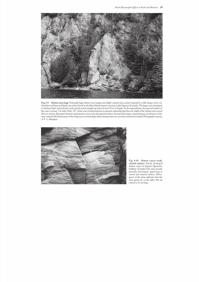
8/8/2019 Traces of Catastrophe - Book
http://slidepdf.com/reader/full/traces-of-catastrophe-book 50/130
Shock-Metamorphic Effects in Rocks and Minerals 39
Fig. 4.9. Shatter cone; huge. Unusually large shatter cone (megacone) (light-colored area, center) exposed in a cliff along a wave-cutshoreline on Patterson Island, one of the islands in the Slate Islands impact structure, Lake Superior (Canada). The huge cone, developedin Archean felsic metavolcanic rocks, points nearly straight up and is at least 10 m in length. At the exposed base, the exposed surface of the cone is at least 7 m wide. Only ~25° of the cone’s basal perimeter is exposed, indicating that the true width of the feature may exceed
20 m at its base. Horsetail striations and parasitic cones cover all exposed surfaces. Several other large, conical features are obvious on thenear-vertical cliff, but because of the steep scree-covered slopes these features have not yet been examined in detail. Photograph courtesy of V. L. Sharpton.
Fig. 4.10. Shatter cones; crude,striated surfaces. Poorly developedshatter cones in Serpent Quartzite,Sudbury (Canada). The cones are only partially developed, appearing ascurved and striated surfaces. Diver-gence of the striae indicates that thecone apexes are to the right. Pen (atcenter) is 12cmlong.
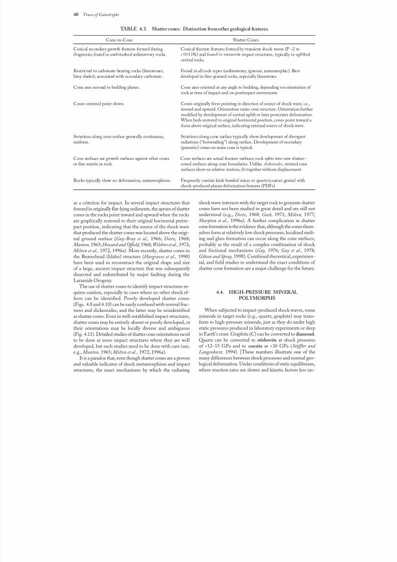
8/8/2019 Traces of Catastrophe - Book
http://slidepdf.com/reader/full/traces-of-catastrophe-book 51/130
40 Traces of Catastrophe
as a criterion for impact. In several impact structures thatformed in originally flat-lying sediments, the apexes of shattercones in the rocks point inward and upward when the rocksare graphically restored to their original horizontal preim-
pact position, indicating that the source of the shock wavethat produced the shatter cones was located above the origi-nal ground surface (Guy-Bray et al., 1966; Dietz, 1968; Manton, 1965;Howard and Offield, 1968; Wilshire et al., 1972; Milton et al., 1972, 1996a). More recently, shatter cones inthe Beaverhead (Idaho) structure (Hargraves et al., 1990)have been used to reconstruct the original shape and sizeof a large, ancient impact structure that was subsequently dissected and redistributed by major faulting during theLaramide Orogeny.
The use of shatter cones to identify impact structures re-quires caution, especially in cases where no other shock ef-fects can be identified. Poorly developed shatter cones
(Figs.4.8 and 4.10) can be easily confused with normal frac-tures and slickensides, and the latter may be misidentifiedas shatter cones. Even in well-established impact structures,shatter cones may be entirely absent or poorly developed, ortheir orientations may be locally diverse and ambiguous(Fig.4.11). Detailed studies of shatter cone orientations needto be done at more impact structures where they are welldeveloped, but such studies need to be done with care (see,e.g., Manton, 1965; Milton et al., 1972, 1996a).
It is a paradox that, even though shatter cones are a provenand valuable indicator of shock metamorphism and impactstructures, the exact mechanisms by which the radiating
TABLE 4.3. Shatter cones: Distinction from other geological features.
Cone-in-Cone Shatter Cones
Conical secondary growth features formed during Conical fracture features formed by transient shock waves (P ~2 todiagenesis; found in undisturbed sedimentary rocks. >10 GPa) and found in meteorite impact structures, typically in uplifted
central rocks.
Restricted to carbonate-bearing rocks (limestones, Found in all rock types (sedimentary, igneous, metamorphic). Best
limy shales); associated with secondary carbonate. developed in fine-grained rocks, especially limestones.
Cone axes normal to bedding planes. Cone axes oriented at any angle to bedding, depending on orientation of rock at time of impact and on postimpact movements.
Cones oriented point-down. Cones originally form pointing in direction of source of shock wave, i.e.,inward and upward. Orientation varies over structure. Orientation furthermodified by development of central uplift or later postcrater deformation.
When beds restored to original horizontal position, cones point toward afocus above original surface, indicating external source of shock wave.
Striations along cone surface generally continuous, Striations along cone surface typically show development of divergentuniform. radiations (“horsetailing”) along surface. Development of secondary
(parasitic) cones on main cone is typical.
Cone surfaces are growth surfaces against other cones Cone surfaces are actual fracture surfaces; rock splits into new shatter-or fine matrix in rock. coned surfaces along cone boundaries. Unlike slickensides, striated cone
surfaces show no relative motion, fit together without displacement.
Rocks typically show no deformation, metamorphism. Frequently contain kink-banded micas or quartz (coarser grains) withshock-produced planar deformation features (PDFs).
shock wave interacts with the target rock to generate shattercones have not been studied in great detail and are still notunderstood (e.g., Dietz, 1968; Gash, 1971; Milton, 1977;Sharpton et al., 1996a). A further complication in shatter
cone formation is the evidence that, although the cones them-selves form at relatively low shock pressures, localized melt-ing and glass formation can occur along the cone surfaces,probably as the result of a complex combination of shock and frictional mechanisms (Gay, 1976; Gay et al., 1978;Gibson and Spray, 1998). Combined theoretical, experimen-tal, and field studies to understand the exact conditions of shatter cone formation are a major challenge for the future.
4.4. HIGH-PRESSURE MINERALPOLYMORPHS
When subjected to impact-produced shock waves, someminerals in target rocks (e.g., quartz, graphite) may trans-form to high-pressure minerals, just as they do under highstatic pressures produced in laboratory experiments or deepin Earth’s crust. Graphite (C) can be converted to diamond.Quartz can be converted to stishovite at shock pressuresof >12–15 GPa and to coesite at >30 GPa (Stöffler and Langenhorst, 1994). [These numbers illustrate one of themany differences between shock processes and normal geo-logical deformation. Under conditions of static equilibrium,
where reaction rates are slower and kinetic factors less im-
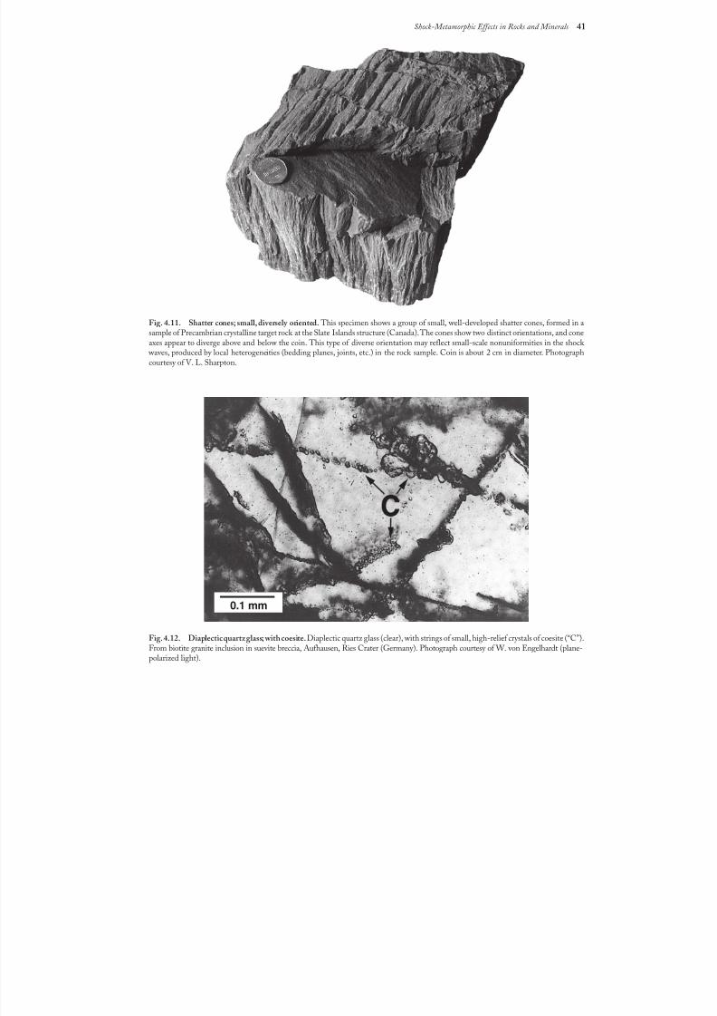
8/8/2019 Traces of Catastrophe - Book
http://slidepdf.com/reader/full/traces-of-catastrophe-book 52/130
Shock-Metamorphic Effects in Rocks and Minerals 41
Fig. 4.11. Shatter cones; small, diversely oriented. This specimen shows a group of small, well-developed shatter cones, formed in asample of Precambrian crystalline target rock at the Slate Islands structure (Canada). The cones show two distinct orientations, and coneaxes appear to diverge above and below the coin. This type of diverse orientation may reflect small-scale nonuniformities in the shock
waves, produced by local heterogeneities (bedding planes, joints, etc.) in the rock sample. Coin is about 2 cm in diameter. Photographcourtesy of V. L. Sharpton.
Fig. 4.12. Diaplectic quartz glass; with coesite.Diaplectic quartz glass (clear), with strings of small, high-relief crystals of coesite (“C”).From biotite granite inclusion in suevite breccia, Aufhausen, Ries Crater (Germany). Photograph courtesy of W. von Engelhardt (plane-polarized light).
0.1 mm
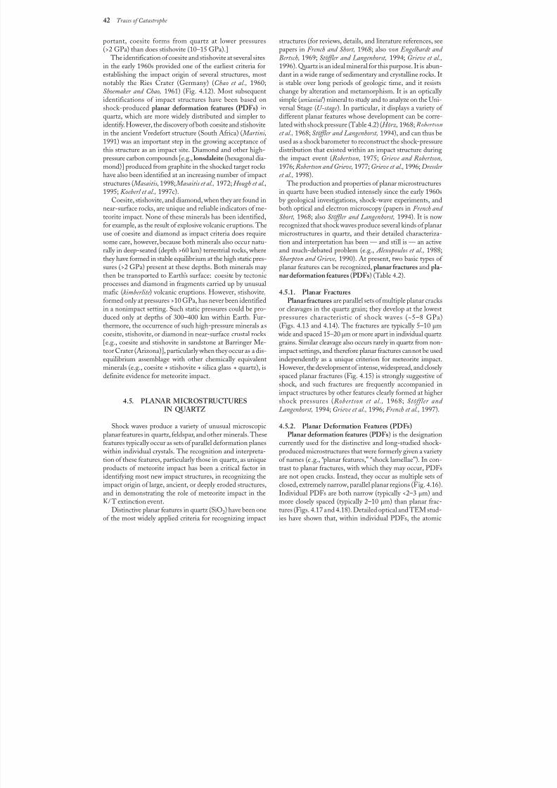
8/8/2019 Traces of Catastrophe - Book
http://slidepdf.com/reader/full/traces-of-catastrophe-book 53/130
42 Traces of Catastrophe
portant, coesite forms from quartz at lower pressures(>2GPa) than does stishovite (10–15 GPa).]
The identification of coesite and stishovite at several sitesin the early 1960s provided one of the earliest criteria forestablishing the impact origin of several structures, mostnotably the Ries Crater (Germany) (Chao et al., 1960;Shoemaker and Chao, 1961) (Fig. 4.12). Most subsequentidentifications of impact structures have been based on
shock-produced planar deformation features (PDFs) inquartz, which are more widely distributed and simpler toidentify. However, the discovery of both coesite and stishovitein the ancient Vredefort structure (South Africa) ( Martini,1991) was an important step in the growing acceptance of this structure as an impact site. Diamond and other high-pressure carbon compounds [e.g., lonsdaleite (hexagonal dia-mond)] produced from graphite in the shocked target rockshave also been identified at an increasing number of impactstructures ( Masaitis, 1998; Masaitis et al., 1972; Hough et al.,1995; Koeberl et al., 1997c).
Coesite, stishovite, and diamond, when they are found innear-surface rocks, are unique and reliable indicators of me-teorite impact. None of these minerals has been identified,for example, as the result of explosive volcanic eruptions. Theuse of coesite and diamond as impact criteria does requiresome care, however, because both minerals also occur natu-rally in deep-seated (depth >60 km) terrestrial rocks, wherethey have formed in stable equilibrium at the high static pres-sures (>2 GPa) present at these depths. Both minerals may then be transported to Earth’s surface: coesite by tectonicprocesses and diamond in fragments carried up by unusualmafic (kimberlite ) volcanic eruptions. However, stishovite,formed only at pressures >10 GPa, has never been identifiedin a nonimpact setting. Such static pressures could be pro-
duced only at depths of 300–400 km within Earth. Fur-thermore, the occurrence of such high-pressure minerals ascoesite, stishovite, or diamond in near-surface crustal rocks[e.g., coesite and stishovite in sandstone at Barringer Me-teor Crater (Arizona)], particularly when they occur as a dis-equilibrium assemblage with other chemically equivalentminerals (e.g., coesite + stishovite + silica glass + quartz), isdefinite evidence for meteorite impact.
4.5. PLANAR MICROSTRUCTURESIN QUARTZ
Shock waves produce a variety of unusual microscopicplanar features in quartz, feldspar, and other minerals. Thesefeatures typically occur as sets of parallel deformation planes
within individual crystals. The recognition and interpreta-tion of these features, particularly those in quartz, as uniqueproducts of meteorite impact has been a critical factor inidentifying most new impact structures, in recognizing theimpact origin of large, ancient, or deeply eroded structures,and in demonstrating the role of meteorite impact in theK/ T extinction event.
Distinctive planar features in quartz (SiO2) have been oneof the most widely applied criteria for recognizing impact
structures (for reviews, details, and literature references, seepapers in French and Short, 1968; also von Engelhardt and Bertsch, 1969; Stöffler and Langenhorst, 1994; Grieve et al.,1996). Quartz is an ideal mineral for this purpose. It is abun-dant in a wide range of sedimentary and crystalline rocks. Itis stable over long periods of geologic time, and it resistschange by alteration and metamorphism. It is an optically simple (uniaxial ) mineral to study and to analyze on the Uni-
versal Stage (U-stage ). In particular, it displays a variety of different planar features whose development can be corre-lated with shock pressure (Table 4.2) (Hörz, 1968; Robertsonet al., 1968; Stöffler and Langenhorst, 1994), and can thus beused as a shock barometer to reconstruct the shock-pressuredistribution that existed within an impact structure duringthe impact event (Robertson, 1975; Grieve and Robertson,1976; Robertson and Grieve, 1977; Grieve et al., 1996; Dressler et al., 1998).
The production and properties of planar microstructuresin quartz have been studied intensely since the early 1960sby geological investigations, shock-wave experiments, andboth optical and electron microscopy (papers in French and Short, 1968; also Stöffler and Langenhorst, 1994). It is now recognized that shock waves produce several kinds of planarmicrostructures in quartz, and their detailed characteriza-tion and interpretation has been — and still is — an activeand much-debated problem (e.g., Alexopoulos et al., 1988;Sharpton and Grieve, 1990). At present, two basic types of planar features can be recognized, planar fractures and pla-nar deformation features (PDFs) (Table 4.2).
4.5.1. Planar FracturesPlanar fractures are parallel sets of multiple planar cracks
or cleavages in the quartz grain; they develop at the lowest
pressures characteristic of shock waves (~5–8 GPa)(Figs.4.13 and 4.14). The fractures are typically 5–10 µm wide and spaced 15–20 µm or more apart in individual quartz grains. Similar cleavage also occurs rarely in quartz from non-impact settings, and therefore planar fractures cannot be usedindependently as a unique criterion for meteorite impact.However, the development of intense, widespread, and closely spaced planar fractures (Fig. 4.15) is strongly suggestive of shock, and such fractures are frequently accompanied inimpact structures by other features clearly formed at highershock pressures (Robertson et al., 1968; Stöffler and Langenhorst, 1994; Grieve et al., 1996; French et al., 1997).
4.5.2. Planar Deformation Features (PDFs)Planar deformation features (PDFs) is the designation
currently used for the distinctive and long-studied shock-produced microstructures that were formerly given a variety of names (e.g., “planar features,” “shock lamellae”). In con-trast to planar fractures, with which they may occur, PDFsare not open cracks. Instead, they occur as multiple sets of closed, extremely narrow, parallel planar regions (Fig. 4.16).Individual PDFs are both narrow (typically <2–3 µm) andmore closely spaced (typically 2–10 µm) than planar frac-tures (Figs. 4.17 and 4.18). Detailed optical and TEM stud-ies have shown that, within individual PDFs, the atomic
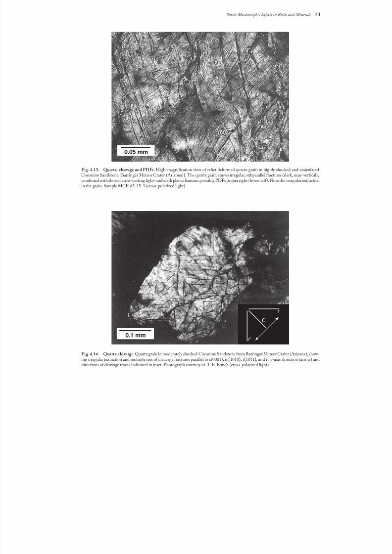
8/8/2019 Traces of Catastrophe - Book
http://slidepdf.com/reader/full/traces-of-catastrophe-book 54/130
Shock-Metamorphic Effects in Rocks and Minerals 43
Fig. 4.13. Quartz; cleavage and PDFs. High-magnification view of relict deformed quartz grain in highly shocked and vesiculatedCoconino Sandstone [Barringer Meteor Crater (Arizona)]. The quartz grain shows irregular, subparallel fractures (dark, near-vertical),combined with shorter cross-cutting light-and-dark planar features, possibly PDFs (upper right/lower left). Note the irregular extinctionin the grain. Sample MCF-65-15-3 (cross-polarized light).
0.05 mm
Fig.4.14. Quartz; cleavage. Quartz grain in moderately shocked Coconino Sandstone from Barringer Meteor Crater (Arizona), show-ing irregular extinction and multiple sets of c leavage fractures parallel to c(0001), m{1010}, r{1011}, and r'. c-axis direction (arrow) anddirections of cleavage traces indicated in inset. Photograph courtesy of T. E. Bunch (cross-polarized light).
0.1 mm
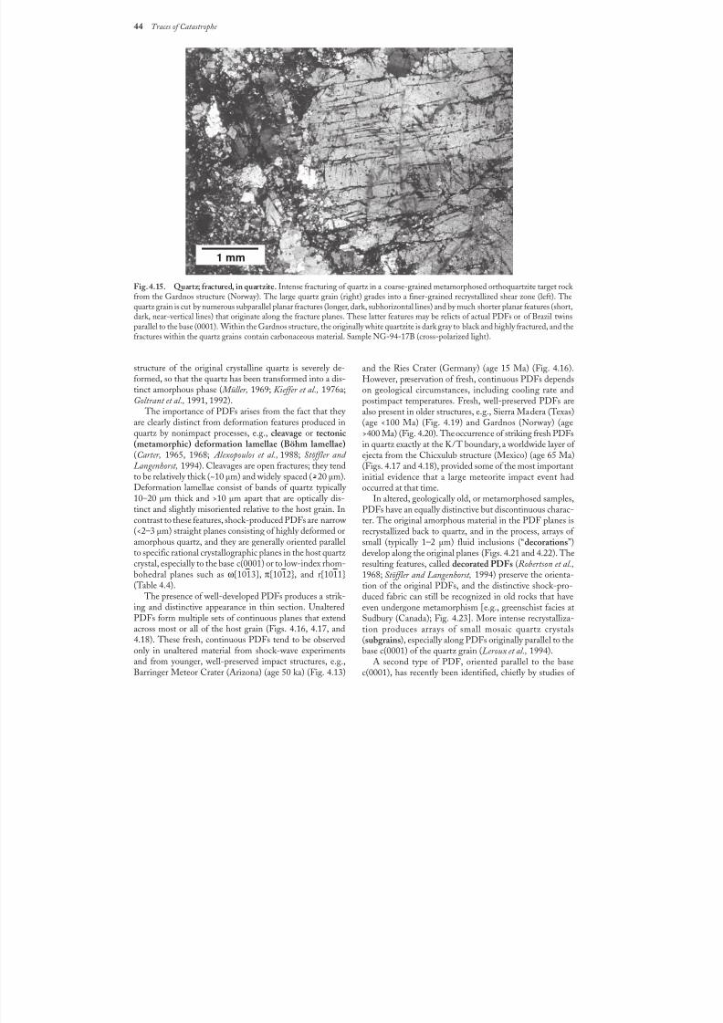
8/8/2019 Traces of Catastrophe - Book
http://slidepdf.com/reader/full/traces-of-catastrophe-book 55/130
44 Traces of Catastrophe
Fig. 4.15. Quartz; fractured, in quartzite. Intense fracturing of quartz in a coarse-grained metamorphosed orthoquartzite target rock from the Gardnos structure (Norway). The large quartz grain (right) grades into a finer-grained recrystallized shear zone (left). Thequartz grain is cut by numerous subparallel planar fractures (longer, dark, subhorizontal lines) and by much shorter planar features (short,dark, near-vertical lines) that originate along the fracture planes. These latter features may be relicts of actual PDFs or of Brazil twinsparallel to the base (0001). Within the Gardnos structure, the originally white quartzite is dark gray to black and highly fractured, and thefractures within the quartz grains contain carbonaceous material. Sample NG-94-17B (cross-polarized light).
and the Ries Crater (Germany) (age 15 Ma) (Fig. 4.16).However, preservation of fresh, continuous PDFs dependson geological circumstances, including cooling rate andpostimpact temperatures. Fresh, well-preserved PDFs are
also present in older structures, e.g., Sierra Madera (Texas)(age <100 Ma) (Fig. 4.19) and Gardnos (Norway) (age>400 Ma) (Fig. 4.20). The occurrence of striking fresh PDFsin quartz exactly at the K/T boundary, a worldwide layer of ejecta from the Chicxulub structure (Mexico) (age 65 Ma)(Figs. 4.17and 4.18), provided some of the most importantinitial evidence that a large meteorite impact event hadoccurred at that time.
In altered, geologically old, or metamorphosed samples,PDFs have an equally distinctive but discontinuous charac-ter. The original amorphous material in the PDF planes isrecrystallized back to quartz, and in the process, arrays of small (typically 1–2 µm) fluid inclusions (“decorations”)
develop along the original planes (Figs. 4.21 and 4.22). Theresulting features, called decorated PDFs (Robertson et al.,1968; Stöffler and Langenhorst, 1994) preserve the orienta-tion of the original PDFs, and the distinctive shock-pro-duced fabric can still be recognized in old rocks that haveeven undergone metamorphism [e.g., greenschist facies atSudbury (Canada); Fig. 4.23]. More intense recrystalliza-tion produces arrays of small mosaic quartz crystals(subgrains), especially along PDFs originally parallel to thebase c(0001) of the quartz grain (Leroux et al., 1994).
A second type of PDF, oriented parallel to the basec(0001), has recently been identified, chiefly by studies of
1 mm
structure of the original crystalline quartz is severely de-formed, so that the quartz has been transformed into a dis-tinct amorphous phase ( Müller, 1969; Kieffer et al., 1976a;Goltrant et al., 1991, 1992).
The importance of PDFs arises from the fact that they are clearly distinct from deformation features produced inquartz by nonimpact processes, e.g., cleavage or tectonic(metamorphic) deformation lamellae (Böhm lamellae)(Carter, 1965, 1968; Alexopoulos et al., 1988; Stöffler and Langenhorst, 1994). Cleavages are open fractures; they tendto be relatively thick (~10 µm) and widely spaced (>20 µm).Deformation lamellae consist of bands of quartz typically 10–20 µm thick and >10 µm apart that are optically dis-tinct and slightly misoriented relative to the host grain. Incontrast to these features, shock-produced PDFs are narrow (<2–3 µm) straight planes consisting of highly deformed oramorphous quartz, and they are generally oriented parallel
to specific rational crystallographic planes in the host quartz crystal, especially to the base c(0001) or to low-index rhom-bohedral planes such as ω{1013}, π{1012}, and r{1011}(Table 4.4).
The presence of well-developed PDFs produces a strik-ing and distinctive appearance in thin section. UnalteredPDFs form multiple sets of continuous planes that extendacross most or all of the host grain (Figs. 4.16, 4.17, and4.18). These fresh, continuous PDFs tend to be observedonly in unaltered material from shock-wave experimentsand from younger, well-preserved impact structures, e.g.,Barringer Meteor Crater (Arizona) (age 50 ka) (Fig.4.13)
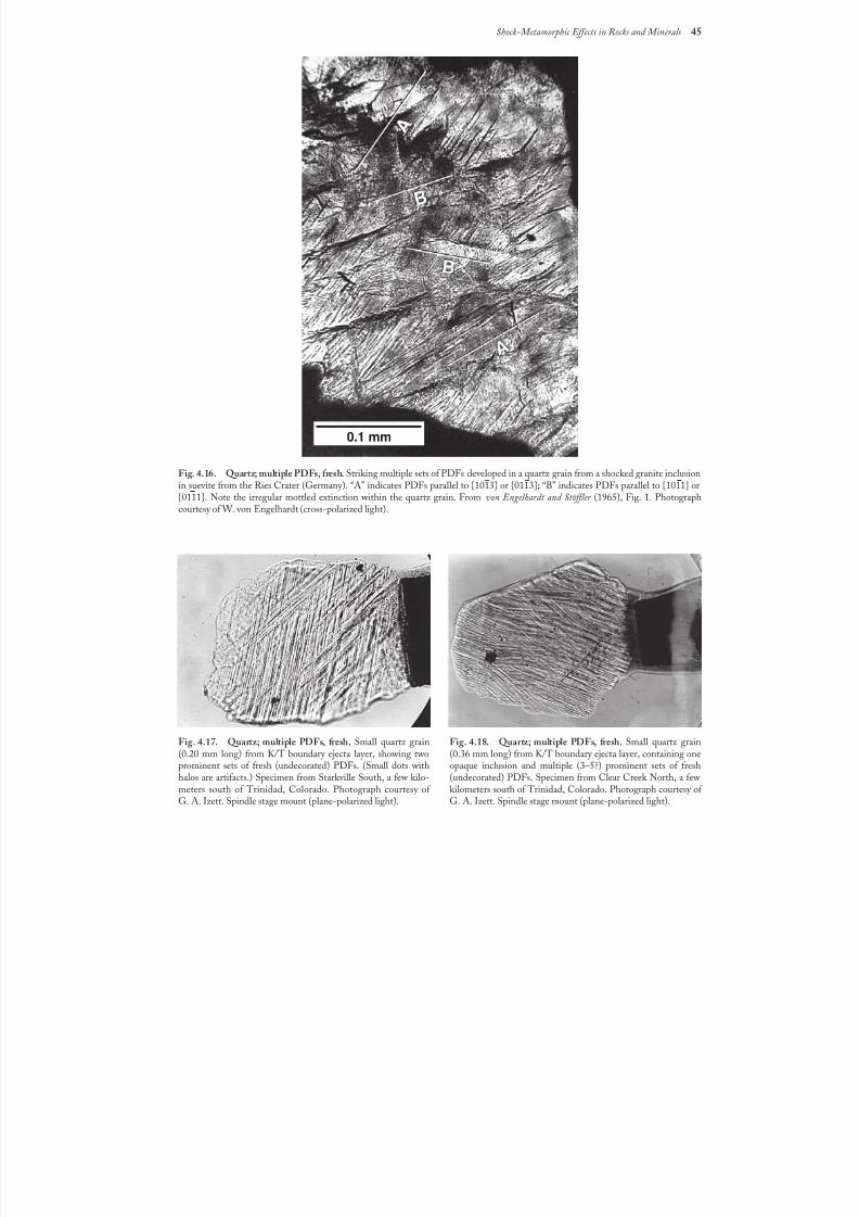
8/8/2019 Traces of Catastrophe - Book
http://slidepdf.com/reader/full/traces-of-catastrophe-book 56/130
Shock-Metamorphic Effects in Rocks and Minerals 45
Fig. 4.17. Quartz; multiple PDFs, fresh. Small quartz grain(0.20 mm long) from K/T boundary ejecta layer, showing twoprominent sets of fresh (undecorated) PDFs. (Small dots withhalos are artifacts.) Specimen from Starkville South, a few kilo-meters south of Trinidad, Colorado. Photograph courtesy of G.A. Izett. Spindle stage mount (plane-polarized light).
Fig. 4.18. Quartz; multiple PDFs, fresh. Small quartz grain(0.36 mm long) from K/T boundary ejecta layer, containing oneopaque inclusion and multiple (3–5?) prominent sets of fresh(undecorated) PDFs. Specimen from Clear Creek North, a few kilometers south of Trinidad, Colorado. Photograph courtesy of G.A. Izett. Spindle stage mount (plane-polarized light).
0.1 mm
Fig. 4.16. Quartz; multiple PDFs, fresh. Striking multiple sets of PDFs developed in a quartz grain from a shocked granite inclusionin suevite from the Ries Crater (Germany). “A” indicates PDFs parallel to {1013} or {0113}; “B” indicates PDFs parallel to {1011} or
{0111}. Note the irregular mottled extinction within the quartz grain. From von Engelhardt and Stöffler (1965), Fig. 1. Photographcourtesy of W. von Engelhardt (cross-polarized light).
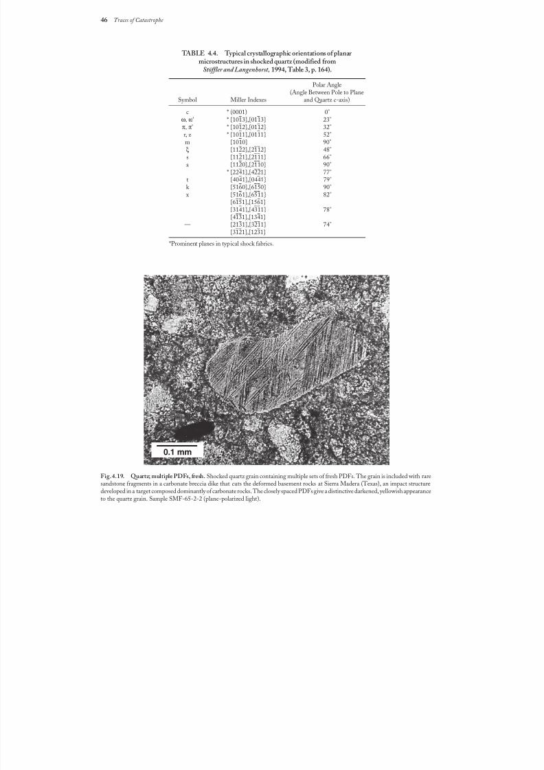
8/8/2019 Traces of Catastrophe - Book
http://slidepdf.com/reader/full/traces-of-catastrophe-book 57/130
46 Traces of Catastrophe
Fig. 4.19. Quartz; multiple PDFs, fresh. Shocked quartz grain containing multiple sets of fresh PDFs. The grain is included with raresandstone fragments in a carbonate breccia dike that cuts the deformed basement rocks at Sierra Madera (Texas), an impact structuredeveloped in a target composed dominantly of carbonate rocks. The closely spaced PDFs give a distinctive darkened, yellowish appearanceto the quartz grain. Sample SMF-65-2-2 (plane-polarized light).
0.1 mm
TABLE4.4. Typical crystallographic orientations of planar microstructures in shocked quartz (modified from
Stöffler and Langenhorst, 1994, Table 3, p. 164).
Polar Angle(Angle Between Pole to Plane
Symbol Miller Indexes and Quartz c-axis)
c * (0001) 0°ω, ω' * {1013},{0113} 23°π, π' * {1012},{0112} 32°r, z * {1011},{0111} 52°m {1010} 90°ξ {1122},{2112} 48°s {1121},{2111} 66°a {1120},{2110} 90°
* {2241},{4221} 77°t {4041},{0441} 79°k {5160},{6150} 90° x {5161},{6511} 82°
{6151},{1561}
— {3141},{4311} 78°{4131},{1341}
— {2131},{3211} 74°{3121},{1231}
*Prominent planes in typical shock fabrics.
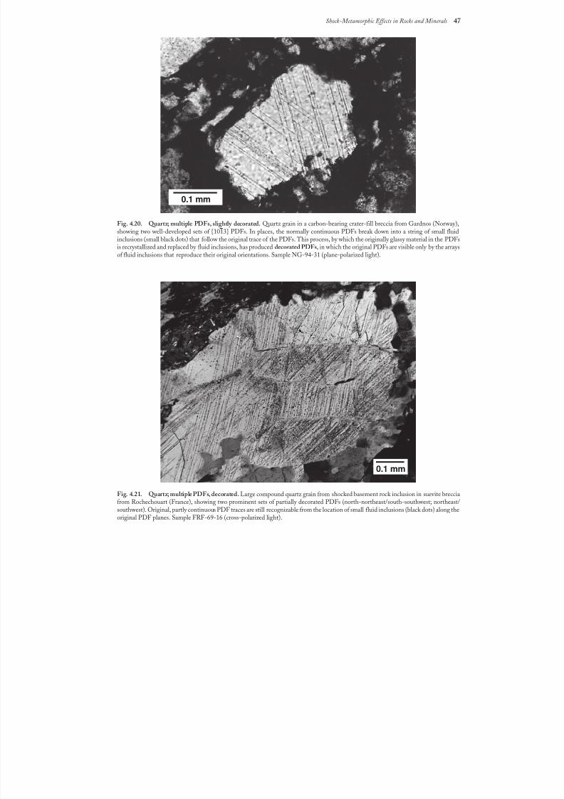
8/8/2019 Traces of Catastrophe - Book
http://slidepdf.com/reader/full/traces-of-catastrophe-book 58/130
Shock-Metamorphic Effects in Rocks and Minerals 47
Fig.4.21. Quartz; multiple PDFs, decorated. Large compound quartz grain from shocked basement rock inclusion in suevite brecciafrom Rochechouart (France), showing two prominent sets of partially decorated PDFs (north-northeast/south-southwest; northeast/southwest). Original, partly continuous PDF traces are still recognizable from the location of small fluid inclusions (black dots) along theoriginal PDF planes. Sample FRF-69-16 (cross-polarized light).
0.1 mm
0.1 mm
Fig.4.20. Quartz; multiple PDFs, slightly decorated. Quartz grain in a carbon-bearing crater-fill breccia from Gardnos (Norway),showing two well-developed sets of {1013} PDFs. In places, the normally continuous PDFs break down into a string of small fluidinclusions (small black dots) that follow the original trace of the PDFs. This process, by which the originally glassy material in the PDFsis recrystallized and replaced by fluid inclusions, has produced decorated PDFs, in which the original PDFs are visible only by the arraysof fluid inclusions that reproduce their original orientations. Sample NG-94-31 (plane-polarized light).
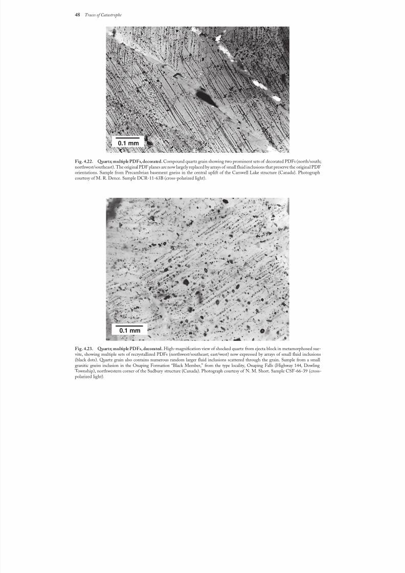
8/8/2019 Traces of Catastrophe - Book
http://slidepdf.com/reader/full/traces-of-catastrophe-book 59/130
48 Traces of Catastrophe
Fig.4.22. Quartz; multiple PDFs, decorated. Compound quartz grain showing two prominent sets of decorated PDFs (north/south;northwest/southeast). The original PDF planes are now largely replaced by arrays of small fluid inclusions that preserve the original PDF orientations. Sample from Precambrian basement gneiss in the central uplift of the Carswell Lake structure (Canada). Photographcourtesy of M. R. Dence. Sample DCR-11-63B (cross-polarized light).
Fig.4.23. Quartz; multiple PDFs, decorated. High-magnification view of shocked quartz from ejecta block in metamorphosed sue- vite, showing multiple sets of recrystallized PDFs (northwest/southeast; east/west) now expressed by arrays of small fluid inclusions(black dots). Quartz grain also contains numerous random larger fluid inclusions scattered through the grain. Sample from a smallgranitic gneiss inclusion in the Onaping Formation “Black Member,” from the type locality, Onaping Falls (Highway 144, Dowling
Township), northwestern corner of the Sudbury structure (Canada). Photograph courtesy of N. M. Short. Sample CSF-66-39 (cross-polarized light).
0.1 mm
0.1 mm
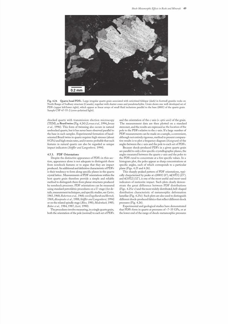
8/8/2019 Traces of Catastrophe - Book
http://slidepdf.com/reader/full/traces-of-catastrophe-book 60/130
Shock-Metamorphic Effects in Rocks and Minerals 49
Fig.4.24. Quartz; basal PDFs. Large irregular quartz grain associated with sericitized feldspar (dark) in footwall granitic rocks onNorth Range of Sudbury structure (Canada), together with shatter cones and pseudotachylite. Grain shows one well-developed set of PDFs (upper left/lower right), which appear as linear arrays of small fluid inclusions parallel to the base (0001) of the quartz grain.Sample CSF-67-55-2 (cross-polarized light).
shocked quartz with transmission election microscopy (TEM), as Brazil twins (Fig. 4.24) (Leroux et al., 1994; Joreauet al., 1996). This form of twinning also occurs in natural
unshocked quartz, but it has never been observed parallel tothe base in such samples. Experimental formation of basal-oriented Brazil twins in quartz requires high stresses (about8 GPa) and high strain rates, and it seems probable that suchfeatures in natural quartz can also be regarded as uniqueimpact indicators (Stöffler and Langenhorst, 1994).
4.5.3. PDF OrientationsDespite the distinctive appearance of PDFs in thin sec-
tion, appearance alone is not adequate to distinguish themfrom nonshock features or to argue that they are impactproduced. An additional and definitive characteristic of PDFsis their tendency to form along specific planes in the quartz
crystal lattice. Measurements of PDF orientations within thehost quartz grain therefore provide a simple and reliablemethod to distinguish them from planar structures producedby nonshock processes. PDF orientations can be measuredusing standard petrofabric procedures on a U-stage (for de-tails, measurement techniques, and specific studies, see Carter,1965, 1968; Robertson et al., 1968; von Engelhardt and Bertsch,1969; Alexopoulos et al., 1988; Stöffler and Langenhorst, 1994)or on the related spindle stage (Bloss, 1981; Medenbach, 1985;Bohor et al., 1984, 1987; Izett, 1990).
The procedures involve measuring, in a single quartz grain,both the orientation of the pole (normal) to each set of PDFs
0.2 mm
and the orientation of the c-axis (= optic axis) of the grain. The measurement data are then plotted on a standardstereonet, and the results are expressed as the location of the
pole to the PDFs relative to the c-axis. If a large number of PDF measurements can be made on a sample, a convenient,although not entirely rigorous, method to present compara-tive results is to plot a frequency diagram (histogram) of theangles between the c-axis and the pole to each set of PDFs.
Because shock-produced PDFs in a given quartz grainare parallel to only a few specific crystallographic planes, theangles measured between the quartz c-axis and the poles tothe PDFs tend to concentrate at a few specific values. In ahistogram plot, the poles appear as sharp concentrations atspecific angles, each of which corresponds to a particularplane (Figs. 4.25 and 4.26).
This sharply peaked pattern of PDF orientations, typi-
cally characterized by peaks at c(0001) (0°), ω{1013} (23°),and π{1012} (32°), is one of the most useful and most-usedindicators of meteorite impact. Such plots clearly demon-strate the great difference between PDF distributions(Figs.4.25a–c) and the more widely distributed, bell-shapeddistribution characteristic of metamorphic deformationlamellae (Fig. 4.25e). Such plots are also used to distinguishdifferent shock-produced fabrics that reflect different shock pressures (Fig. 4.26).
Experimental and geological studies have demonstratedthat PDFs form in quartz at pressures of ~7–35 GPa, or atthe lower end of the range of shock-metamorphic pressures
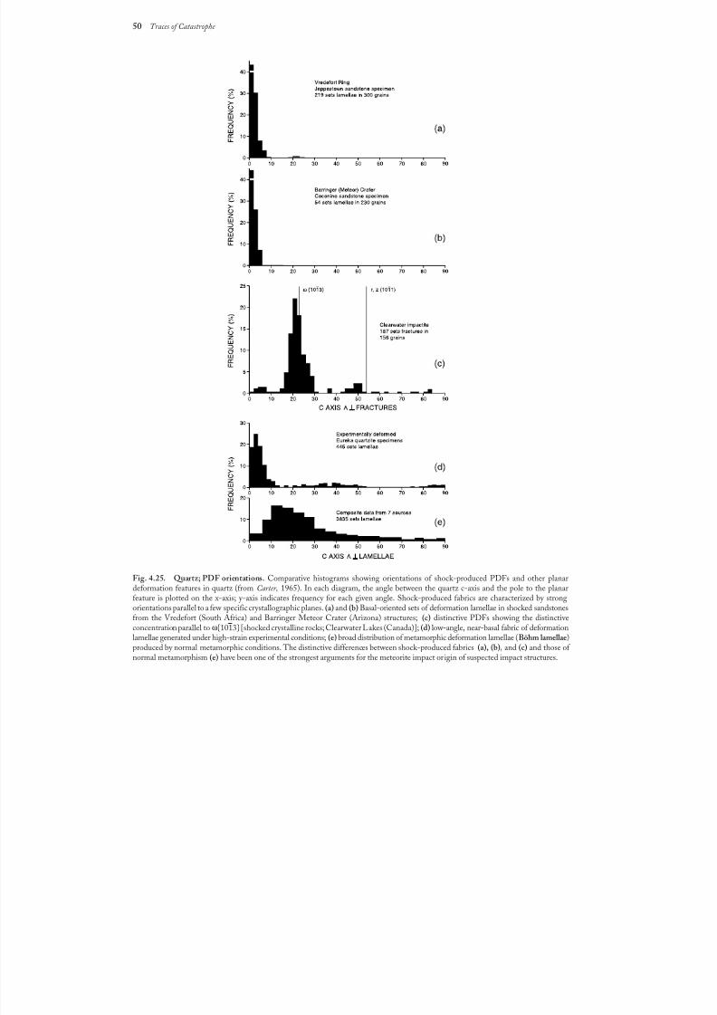
8/8/2019 Traces of Catastrophe - Book
http://slidepdf.com/reader/full/traces-of-catastrophe-book 61/130
50 Traces of Catastrophe
Fig. 4.25. Quartz; PDF orientations. Comparative histograms showing orientations of shock-produced PDFs and other planardeformation features in quartz (from Carter, 1965). In each diagram, the angle between the quartz c-axis and the pole to the planarfeature is plotted on the x-axis; y-axis indicates frequency for each given angle. Shock-produced fabrics are characterized by strongorientations parallel to a few specific crystallographic planes.(a) and (b) Basal-oriented sets of deformation lamellae in shocked sandstonesfrom the Vredefort (South Africa) and Barringer Meteor Crater (Arizona) structures; (c) distinctive PDFs showing the distinctiveconcentration parallel to ω{1013} [shocked crystalline rocks; Clearwater Lakes (Canada)]; (d) low-angle, near-basal fabric of deformationlamellae generated under high-strain experimental conditions; (e) broad distribution of metamorphic deformation lamellae (Böhm lamellae)produced by normal metamorphic conditions. The distinctive differences between shock-produced fabrics (a), (b), and (c) and those of normal metamorphism (e) have been one of the strongest arguments for the meteorite impact origin of suspected impact structures.
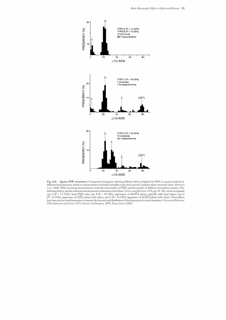
8/8/2019 Traces of Catastrophe - Book
http://slidepdf.com/reader/full/traces-of-catastrophe-book 62/130
Shock-Metamorphic Effects in Rocks and Minerals 51
Fig. 4.26. Quartz; PDF orientations. Comparative histograms showing different fabrics displayed by PDFs in quartz produced atdifferent shock pressures, based on measurements of shocked crystalline rocks from several Canadian impact structures (from Robertsonet al., 1968). With increasing shock pressures, both the total number of PDFs and the number of different orientations increase. Thefollowing fabrics, and the minimum shock pressures estimated to form them (Grieve and Robertson, 1976, pp. 39– 40), can be recognized:type A (P > 7.5 GPa): basal PDFs only; type B (P > 10 GPa), appearance of ω{1013} planes, typically with basal planes; type C (P > 14 GPa), appearance of {2241} planes with others; type D (P > 16 GPa), appearance of π{1012} planes with others. These fabricshave been used as shock barometers to measure the intensity and distribution of shock pressures in several structures (Grieve and Robertson,1976; Robertson and Grieve, 1977; Dressler and Sharpton, 1997). From Carter (1965).
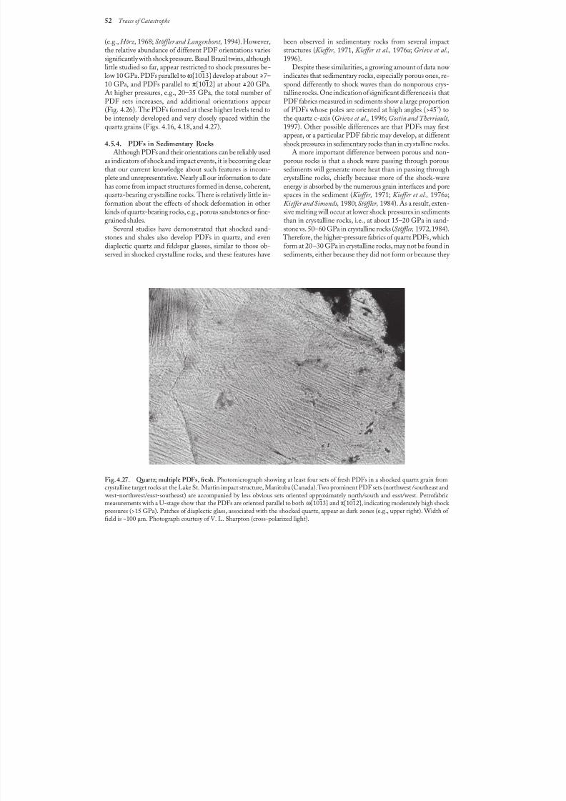
8/8/2019 Traces of Catastrophe - Book
http://slidepdf.com/reader/full/traces-of-catastrophe-book 63/130
52 Traces of Catastrophe
been observed in sedimentary rocks from several impactstructures (Kieffer, 1971, Kieffer et al., 1976a; Grieve et al.,1996).
Despite these similarities, a growing amount of data now indicates that sedimentary rocks, especially porous ones, re-spond differently to shock waves than do nonporous crys-talline rocks. One indication of significant differences is thatPDF fabrics measured in sediments show a large proportion
of PDFs whose poles are oriented at high angles (>45°) tothe quartz c-axis (Grieve et al., 1996; Gostin and Therriault,1997). Other possible differences are that PDFs may firstappear, or a particular PDF fabric may develop, at differentshock pressures in sedimentary rocks than in crystalline rocks.
A more important difference between porous and non-porous rocks is that a shock wave passing through poroussediments will generate more heat than in passing throughcrystalline rocks, chiefly because more of the shock-waveenergy is absorbed by the numerous grain interfaces and porespaces in the sediment (Kieffer, 1971; Kieffer et al., 1976a;Kieffer and Simonds, 1980; Stöffler, 1984). As a result, exten-sive melting will occur at lower shock pressures in sedimentsthan in crystalline rocks, i.e., at about 15–20 GPa in sand-stone vs. 50–60 GPa in crystalline rocks (Stöffler, 1972, 1984).
Therefore, the higher-pressure fabrics of quartz PDFs, whichform at 20–30 GPa in crystalline rocks, may not be found insediments, either because they did not form or because they
Fig. 4.27. Quartz; multiple PDFs, fresh. Photomicrograph showing at least four sets of fresh PDFs in a shocked quartz grain fromcrystalline target rocks at the Lake St. Martin impact structure, Manitoba (Canada). Two prominent PDF sets (northwest /southeast and
west-northwest/east-southeast) are accompanied by less obvious sets oriented approximately north/south and east/west. Petrofabricmeasurements with a U-stage show that the PDFs are oriented parallel to both ω{1013} and π{1012}, indicating moderately high shock pressures (>15 GPa). Patches of diaplectic glass, associated with the shocked quartz, appear as dark zones (e.g., upper right). Width of field is ~100 µm. Photograph courtesy of V. L. Sharpton (cross-polarized light).
(e.g., Hörz, 1968; Stöffler and Langenhorst, 1994). However,the relative abundance of different PDF orientations variessignificantly with shock pressure. Basal Brazil twins, althoughlittle studied so far, appear restricted to shock pressures be-low 10 GPa. PDFs parallel to ω{1013} develop at about >7–10 GPa, and PDFs parallel to π{1012} at about >20 GPa.At higher pressures, e.g., 20–35 GPa, the total number of PDF sets increases, and additional orientations appear
(Fig.4.26). The PDFs formed at these higher levels tend tobe intensely developed and very closely spaced within thequartz grains (Figs.4.16, 4.18, and 4.27).
4.5.4. PDFs in Sedimentary RocksAlthough PDFs and their orientations can be reliably used
as indicators of shock and impact events, it is becoming clearthat our current knowledge about such features is incom-plete and unrepresentative. Nearly all our information to datehas come from impact structures formed in dense, coherent,quartz-bearing crystalline rocks. There is relatively little in-formation about the effects of shock deformation in otherkinds of quartz-bearing rocks, e.g., porous sandstones or fine-grained shales.
Several studies have demonstrated that shocked sand-stones and shales also develop PDFs in quartz, and evendiaplectic quartz and feldspar glasses, similar to those ob-served in shocked crystalline rocks, and these features have
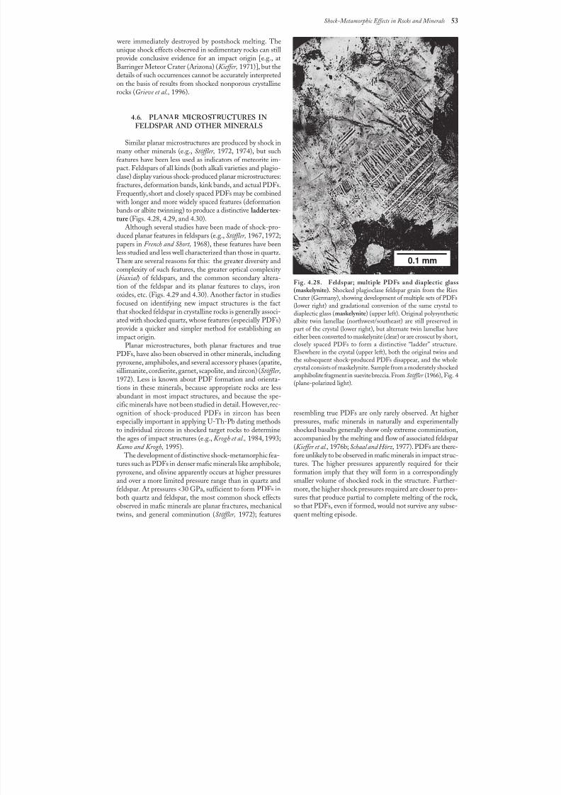
8/8/2019 Traces of Catastrophe - Book
http://slidepdf.com/reader/full/traces-of-catastrophe-book 64/130
Shock-Metamorphic Effects in Rocks and Minerals 53
were immediately destroyed by postshock melting. Theunique shock effects observed in sedimentary rocks can stillprovide conclusive evidence for an impact origin [e.g., atBarringer Meteor Crater (Arizona) (Kieffer, 1971)], but thedetails of such occurrences cannot be accurately interpretedon the basis of results from shocked nonporous crystallinerocks (Grieve et al., 1996).
4.6. PLANAR MICROSTRUCTURES INFELDSPAR AND OTHER MINERALS
Similar planar microstructures are produced by shock inmany other minerals (e.g., Stöffler, 1972, 1974), but suchfeatures have been less used as indicators of meteorite im-pact. Feldspars of all kinds (both alkali varieties and plagio-clase) display various shock-produced planar microstructures:fractures, deformation bands, kink bands, and actual PDFs.Frequently, short and closely spaced PDFs may be combined
with longer and more widely spaced features (deformationbands or albite twinning) to produce a distinctive ladder tex-ture (Figs. 4.28, 4.29, and 4.30).
Although several studies have been made of shock-pro-duced planar features in feldspars (e.g., Stöffler, 1967, 1972;papers in French and Short, 1968), these features have beenless studied and less well characterized than those in quartz.
There are several reasons for this: the greater diversity andcomplexity of such features, the greater optical complexity (biaxial ) of feldspars, and the common secondary altera-tion of the feldspar and its planar features to clays, ironoxides, etc. (Figs. 4.29 and 4.30). Another factor in studiesfocused on identifying new impact structures is the factthat shocked feldspar in crystalline rocks is generally associ-
ated with shocked quartz, whose features (especially PDFs)provide a quicker and simpler method for establishing animpact origin.
Planar microstructures, both planar fractures and truePDFs, have also been observed in other minerals, includingpyroxene, amphiboles, and several accessory phases (apatite,sillimanite, cordierite, garnet, scapolite, and zircon) (Stöffler,1972). Less is known about PDF formation and orienta-tions in these minerals, because appropriate rocks are lessabundant in most impact structures, and because the spe-cific minerals have not been studied in detail. However, rec-ognition of shock-produced PDFs in zircon has beenespecially important in applying U-Th-Pb dating methods
to individual zircons in shocked target rocks to determinethe ages of impact structures (e.g., Krogh et al., 1984, 1993;Kamo and Krogh, 1995).
The development of distinctive shock-metamorphic fea-tures such as PDFs in denser mafic minerals like amphibole,pyroxene, and olivine apparently occurs at higher pressuresand over a more limited pressure range than in quartz andfeldspar. At pressures <30 GPa, sufficient to form PDFs inboth quartz and feldspar, the most common shock effectsobserved in mafic minerals are planar fractures, mechanicaltwins, and general comminution (Stöffler, 1972); features
Fig. 4.28. Feldspar; multiple PDFs and diaplectic glass(maskelynite). Shocked plagioclase feldspar grain from the RiesCrater (Germany), showing development of multiple sets of PDFs(lower right) and gradational conversion of the same crystal todiaplectic glass (maskelynite) (upper left). Original polysynthetic
albite twin lamellae (northwest/southeast) are still preserved inpart of the crystal (lower right), but alternate twin lamellae haveeither been converted to maskelynite (clear) or are crosscut by short,closely spaced PDFs to form a distinctive “ladder” structure.Elsewhere in the crystal (upper left), both the original twins andthe subsequent shock-produced PDFs disappear, and the wholecrystal consists of maskelynite. Sample from a moderately shockedamphibolite fragment in suevite breccia. From Stöffler (1966), Fig.4(plane-polarized light).
resembling true PDFs are only rarely observed. At higherpressures, mafic minerals in naturally and experimentally
shocked basalts generally show only extreme comminution,accompanied by the melting and flow of associated feldspar(Kieffer et al., 1976b; Schaal and Hörz, 1977). PDFs are there-fore unlikely to be observed in mafic minerals in impact struc-tures. The higher pressures apparently required for theirformation imply that they will form in a correspondingly smaller volume of shocked rock in the structure. Further-more, the higher shock pressures required are closer to pres-sures that produce partial to complete melting of the rock,so that PDFs, even if formed, would not survive any subse-quent melting episode.
0.1 mm
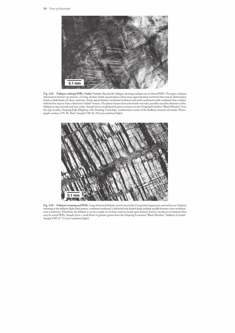
8/8/2019 Traces of Catastrophe - Book
http://slidepdf.com/reader/full/traces-of-catastrophe-book 65/130
54 Traces of Catastrophe
Fig.4.29. Feldspar; multiple PDFs, “ladder” texture. Shocked K-feldspar, showing multiple sets of altered PDFs. Two types of planardeformation features are present: (1) long, thicker, widely spaced planes (clear areas, approximately east/west) that may be deformationbands or kink bands; (2) short, narrower, closely spaced features (northeast/southwest and north-northwest/south-southeast) that combine
with the first type to form a distinctive “ladder” texture. The planar features have a brownish-red color, possibly caused by alteration of thefeldspar to clay minerals and iron oxides. Sample from a small granitic gneiss inclusion in the Onaping Formation “Black Member” fromthe type locality, Onaping Falls (Highway 144, Dowling Township), northwestern corner of the Sudbury structure (Canada). Photo-graph courtesy of N. M. Short. Sample CSF-66-39 (cross-polarized light).
Fig.4.30. Feldspar; twinning and PDFs. Large deformed feldspar crystal (microcline?) in granitic fragment in suevite breccia. Originaltwinning in the feldspar (light/dark pattern, northwest/southeast) is deformed and faulted along multiple parallel fractures (east-northeast/
west-southwest). Elsewhere, the feldspar is cut by a single set of short, narrow, closely spaced planar features (northeast/southwest) thatmay be actual PDFs. Sample from a small block of granitic gneiss from the Onaping Formation “Black Member,” Sudbury (Canada).Sample CSF-67-73 (cross-polarized light).
0.1 mm
0.1 mm
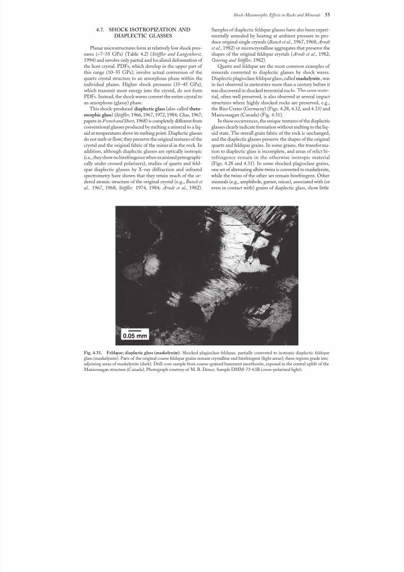
8/8/2019 Traces of Catastrophe - Book
http://slidepdf.com/reader/full/traces-of-catastrophe-book 66/130
Shock-Metamorphic Effects in Rocks and Minerals 55
4.7. SHOCK ISOTROPIZATION ANDDIAPLECTIC GLASSES
Planar microstructures form at relatively low shock pres-sures (>7–35 GPa) (Table 4.2) (Stöffler and Langenhorst,1994) and involve only partial and localized deformation of the host crystal. PDFs, which develop in the upper part of this range (10–35 GPa), involve actual conversion of the
quartz crystal structure to an amorphous phase within theindividual planes. Higher shock pressures (35–45 GPa),
which transmit more energy into the crystal, do not formPDFs. Instead, the shock waves convert the entire crystal toan amorphous (glassy) phase.
This shock-produced diaplectic glass (also called theto-morphic glass) (Stöffler,1966, 1967, 1972, 1984; Chao, 1967;papers in French and Short, 1968) is completely different fromconventional glasses produced by melting a mineral to a liq-uid at temperatures above its melting point. Diaplectic glassesdo not melt or flow; they preserve the original textures of thecrystal and the original fabric of the mineral in the rock. Inaddition, although diaplectic glasses are optically isotropic(i.e., they show no birefringence when examined petrographi-cally under crossed polarizers), studies of quartz and feld-spar diaplectic glasses by X-ray diffraction and infraredspectrometry have shown that they retain much of the or-dered atomic structure of the original crystal (e.g., Bunch et al., 1967, 1968; Stöffler, 1974, 1984; Arndt et al., 1982).
Samples of diaplectic feldspar glasses have also been experi-mentally annealed by heating at ambient pressure to pro-duce original single crystals (Bunch et al., 1967, 1968; Arndt et al., 1982) or microcrystalline aggregates that preserve theshapes of the original feldspar crystals ( Arndt et al., 1982;Ostertag and Stöffler, 1982).
Quartz and feldspar are the most common examples of minerals converted to diaplectic glasses by shock waves.
Diaplectic plagioclase feldspar glass, called maskelynite, wasin fact observed in meteorites more than a century before it
was discovered in shocked terrestrial rocks. The same mate-rial, often well preserved, is also observed at several impactstructures where highly shocked rocks are preserved, e.g.,the Ries Crater (Germany) (Figs. 4.28, 4.32, and 4.33) andManicouagan (Canada) (Fig. 4.31).
In these occurrences, the unique textures of the diaplecticglasses clearly indicate formation without melting to the liq-uid state. The overall grain fabric of the rock is unchanged,and the diaplectic glasses preserve the shapes of the originalquartz and feldspar grains. In some grains, the transforma-tion to diaplectic glass is incomplete, and areas of relict bi-refringence remain in the otherwise isotropic material(Figs.4.28 and 4.31). In some shocked plagioclase grains,one set of alternating albite twins is converted to maskelynite,
while the twins of the other set remain birefringent. Otherminerals (e.g., amphibole, garnet, micas), associated with (oreven in contact with) grains of diaplectic glass, show little
Fig. 4.31. Feldspar; diaplectic glass (maskelynite). Shocked plagioclase feldspar, partially converted to isotropic diaplectic feldsparglass (maskelynite). Parts of the original coarse feldspar grains remain crystalline and birefringent (light areas); these regions grade intoadjoining areas of maskelynite (dark). Drill-core sample from coarse-grained basement anorthosite, exposed in the central uplift of theManicouagan structure (Canada). Photograph courtesy of M. R. Dence. Sample DMM-73-63B (cross-polarized light).
0.05 mm
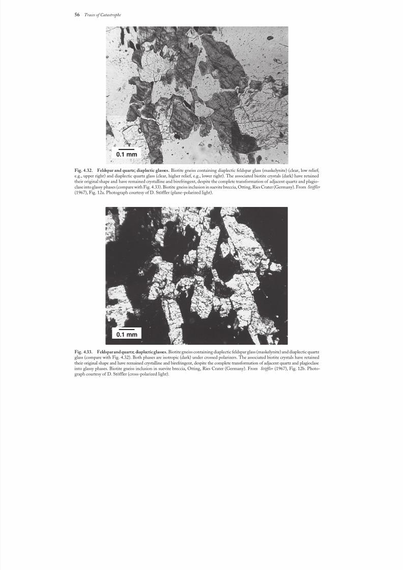
8/8/2019 Traces of Catastrophe - Book
http://slidepdf.com/reader/full/traces-of-catastrophe-book 67/130
56 Traces of Catastrophe
Fig. 4.32. Feldspar and quartz; diaplectic glasses. Biotite gneiss containing diaplectic feldspar glass (maskelynite) (clear, low relief;e.g., upper right) and diaplectic quartz glass (clear, higher relief, e.g., lower right). The associated biotite crystals (dark) have retainedtheir original shape and have remained crystalline and birefringent, despite the complete transformation of adjacent quartz and plagio-clase into glassy phases (compare with Fig. 4.33). Biotite gneiss inclusion in suevite breccia, Otting, Ries Crater (Germany). From Stöffler (1967), Fig. 12a. Photograph courtesy of D. Stöffler (plane-polarized light).
Fig.4.33. Feldspar and quartz; diaplectic glasses. Biotite gneiss containing diaplectic feldspar glass (maskelynite) and diaplectic quartz glass (compare with Fig. 4.32). Both phases are isotropic (dark) under crossed polarizers. The associated biotite crystals have retainedtheir original shape and have remained crystalline and birefringent, despite the complete transformation of adjacent quartz and plagioclaseinto glassy phases. Biotite gneiss inclusion in suevite breccia, Otting, Ries Crater (Germany). From Stöffler (1967), Fig.12b. Photo-graph courtesy of D. Stöffler (cross-polarized light).
0.1 mm
0.1 mm
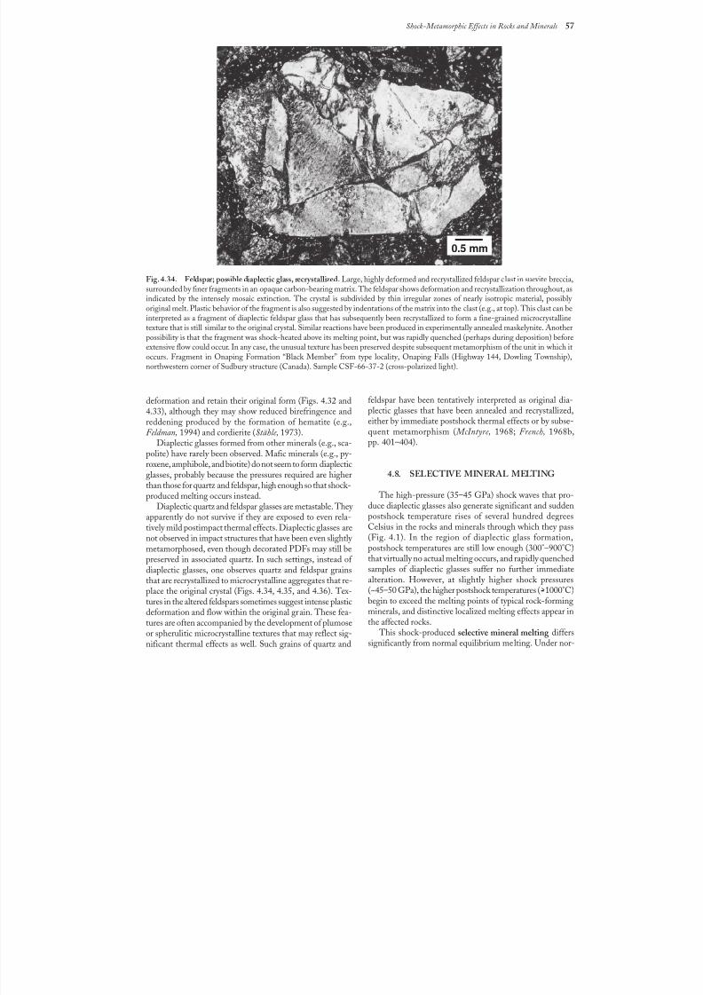
8/8/2019 Traces of Catastrophe - Book
http://slidepdf.com/reader/full/traces-of-catastrophe-book 68/130
Shock-Metamorphic Effects in Rocks and Minerals 57
deformation and retain their original form (Figs. 4.32 and4.33), although they may show reduced birefringence andreddening produced by the formation of hematite (e.g.,Feldman, 1994) and cordierite (Stähle, 1973).
Diaplectic glasses formed from other minerals (e.g., sca-polite) have rarely been observed. Mafic minerals (e.g., py-roxene, amphibole, and biotite) do not seem to form diaplecticglasses, probably because the pressures required are higherthan those for quartz and feldspar, high enough so that shock-produced melting occurs instead.
Diaplectic quartz and feldspar glasses are metastable. They apparently do not survive if they are exposed to even rela-tively mild postimpact thermal effects. Diaplectic glasses are
not observed in impact structures that have been even slightly metamorphosed, even though decorated PDFs may still bepreserved in associated quartz. In such settings, instead of diaplectic glasses, one observes quartz and feldspar grainsthat are recrystallized to microcrystalline aggregates that re-place the original crystal (Figs. 4.34, 4.35, and 4.36). Tex-tures in the altered feldspars sometimes suggest intense plasticdeformation and flow within the original grain. These fea-tures are often accompanied by the development of plumoseor spherulitic microcrystalline textures that may reflect sig-nificant thermal effects as well. Such grains of quartz and
Fig. 4.34. Feldspar; possible diaplectic glass, recrystallized. Large, highly deformed and recrystallized feldspar c last in suevite breccia,surrounded by finer fragments in an opaque carbon-bearing matrix. The feldspar shows deformation and recrystallization throughout, asindicated by the intensely mosaic extinction. The crystal is subdivided by thin irregular zones of nearly isotropic material, possibly original melt. Plastic behavior of the fragment is also suggested by indentations of the matrix into the clast (e.g., at top). This clast can beinterpreted as a fragment of diaplectic feldspar glass that has subsequently been recrystallized to form a fine-grained microcrystallinetexture that is still similar to the original crystal. Similar reactions have been produced in experimentally annealed maskelynite. Anotherpossibility is that the fragment was shock-heated above its melting point, but was rapidly quenched (perhaps during deposition) beforeextensive flow could occur. In any case, the unusual texture has been preserved despite subsequent metamorphism of the unit in which itoccurs. Fragment in Onaping Formation “Black Member” from type locality, Onaping Falls (Highway 144, Dowling Township),northwestern corner of Sudbury structure (Canada). Sample CSF-66-37-2 (cross-polarized light).
feldspar have been tentatively interpreted as original dia-plectic glasses that have been annealed and recrystallized,either by immediate postshock thermal effects or by subse-quent metamorphism ( McIntyre, 1968; French, 1968b,pp. 401–404).
4.8. SELECTIVE MINERAL MELTING
The high-pressure (35–45 GPa) shock waves that pro-duce diaplectic glasses also generate significant and suddenpostshock temperature rises of several hundred degreesCelsius in the rocks and minerals through which they pass
(Fig.4.1). In the region of diaplectic glass formation,postshock temperatures are still low enough (300°–900°C)that virtually no actual melting occurs, and rapidly quenchedsamples of diaplectic glasses suffer no further immediatealteration. However, at slightly higher shock pressures(~45–50 GPa), the higher postshock temperatures (>1000°C)begin to exceed the melting points of typical rock-formingminerals, and distinctive localized melting effects appear inthe affected rocks.
This shock-produced selective mineral melting differssignificantly from normal equilibrium melting. Under nor-
0.5 mm
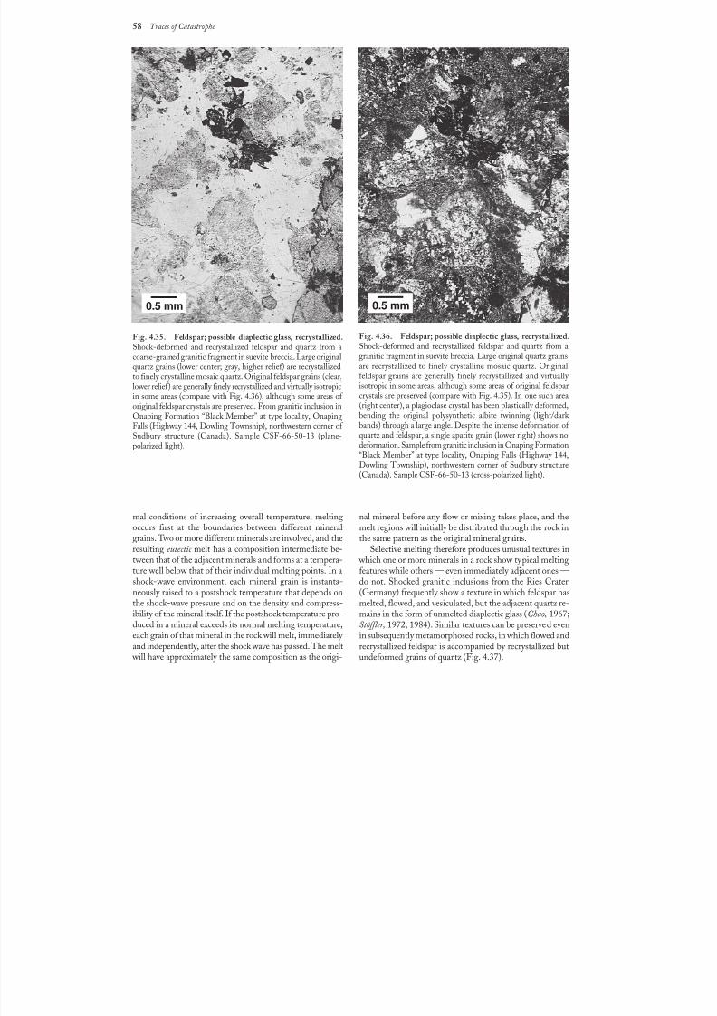
8/8/2019 Traces of Catastrophe - Book
http://slidepdf.com/reader/full/traces-of-catastrophe-book 69/130
58 Traces of Catastrophe
Fig.4.35. Feldspar; possible diaplectic glass, recrystallized.Shock-deformed and recrystallized feldspar and quartz from acoarse-grained granitic fragment in suevite breccia. Large originalquartz grains (lower center; gray, higher relief) are recrystallizedto finely crystalline mosaic quartz. Original feldspar grains (clear,lower relief) are generally finely recrystallized and virtually isotropicin some areas (compare with Fig. 4.36), although some areas of original feldspar crystals are preserved. From granitic inclusion inOnaping Formation “Black Member” at type locality, OnapingFalls (Highway 144, Dowling Township), northwestern corner of Sudbury structure (Canada). Sample CSF-66-50-13 (plane-polarized light).
Fig.4.36. Feldspar; possible diaplectic glass, recrystallized.Shock-deformed and recrystallized feldspar and quartz from agranitic fragment in suevite breccia. Large original quartz grainsare recrystallized to finely crystalline mosaic quartz. Originalfeldspar grains are generally finely recrystallized and virtually isotropic in some areas, although some areas of original feldsparcrystals are preserved (compare with Fig. 4.35). In one such area(right center), a plagioclase crystal has been plastically deformed,bending the original polysynthetic albite twinning (light/dark bands) through a large angle. Despite the intense deformation of quartz and feldspar, a single apatite grain (lower right) shows nodeformation. Sample from granitic inclusion in Onaping Formation“Black Member” at type locality, Onaping Falls (Highway 144,Dowling Township), northwestern corner of Sudbury structure(Canada). Sample CSF-66-50-13 (cross-polarized light).
mal conditions of increasing overall temperature, meltingoccurs first at the boundaries between different mineralgrains. Two or more different minerals are involved, and the
resulting eutectic melt has a composition intermediate be-tween that of the adjacent minerals and forms at a tempera-ture well below that of their individual melting points. In ashock-wave environment, each mineral grain is instanta-neously raised to a postshock temperature that depends onthe shock-wave pressure and on the density and compress-ibility of the mineral itself. If the postshock temperature pro-duced in a mineral exceeds its normal melting temperature,each grain of that mineral in the rock will melt, immediately and independently, after the shock wave has passed. The melt
will have approximately the same composition as the origi-
nal mineral before any flow or mixing takes place, and themelt regions will initially be distributed through the rock inthe same pattern as the original mineral grains.
Selective melting therefore produces unusual textures in which one or more minerals in a rock show typical meltingfeatures while others — even immediately adjacent ones —do not. Shocked granitic inclusions from the Ries Crater(Germany) frequently show a texture in which feldspar hasmelted, flowed, and vesiculated, but the adjacent quartz re-mains in the form of unmelted diaplectic glass (Chao, 1967;Stöffler, 1972, 1984). Similar textures can be preserved evenin subsequently metamorphosed rocks, in which flowed andrecrystallized feldspar is accompanied by recrystallized butundeformed grains of quartz (Fig. 4.37).
0.5 mm 0.5 mm
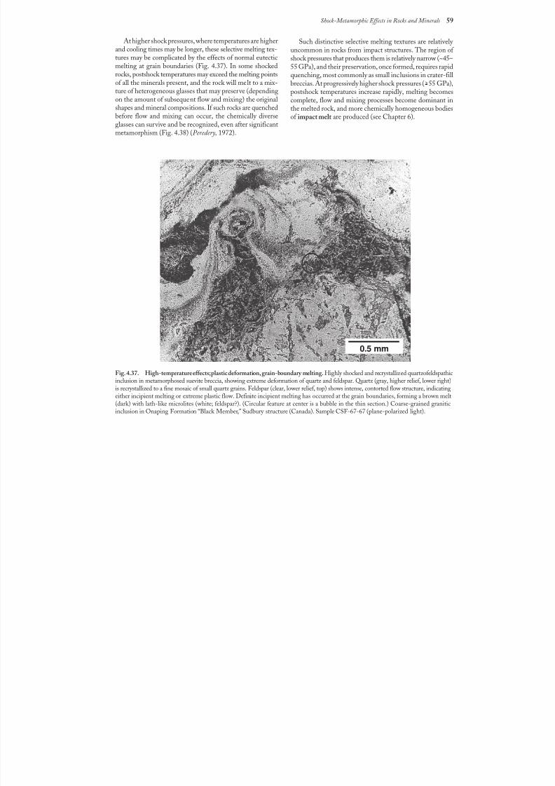
8/8/2019 Traces of Catastrophe - Book
http://slidepdf.com/reader/full/traces-of-catastrophe-book 70/130
Shock-Metamorphic Effects in Rocks and Minerals 59
Fig. 4.37. High-temperature effects; plastic deformation, grain-boundary melting. Highly shocked and recrystallized quartzofeldspathicinclusion in metamorphosed suevite breccia, showing extreme deformation of quartz and feldspar. Quartz (gray, higher relief, lower right)is recrystallized to a fine mosaic of small quartz grains. Feldspar (clear, lower relief, top) shows intense, contorted flow structure, indicatingeither incipient melting or extreme plastic flow. Definite incipient melting has occurred at the grain boundaries, forming a brown melt(dark) with lath-like microlites (white; feldspar?). (Circular feature at center is a bubble in the thin section.) Coarse-grained graniticinclusion in Onaping Formation “Black Member,” Sudbury structure (Canada). Sample CSF-67-67 (plane-polarized light).
At higher shock pressures, where temperatures are higherand cooling times may be longer, these selective melting tex-tures may be complicated by the effects of normal eutecticmelting at grain boundaries (Fig. 4.37). In some shockedrocks, postshock temperatures may exceed the melting pointsof all the minerals present, and the rock will melt to a mix-ture of heterogeneous glasses that may preserve (dependingon the amount of subsequent flow and mixing) the original
shapes and mineral compositions. If such rocks are quenchedbefore flow and mixing can occur, the chemically diverseglasses can survive and be recognized, even after significantmetamorphism (Fig. 4.38) (Peredery, 1972).
Such distinctive selective melting textures are relatively uncommon in rocks from impact structures. The region of shock pressures that produces them is relatively narrow (~45–55 GPa), and their preservation, once formed, requires rapidquenching, most commonly as small inclusions in crater-fillbreccias. At progressively higher shock pressures (>55 GPa),postshock temperatures increase rapidly, melting becomescomplete, flow and mixing processes become dominant in
the melted rock, and more chemically homogeneous bodiesof impact melt are produced (see Chapter 6).
0.5 mm
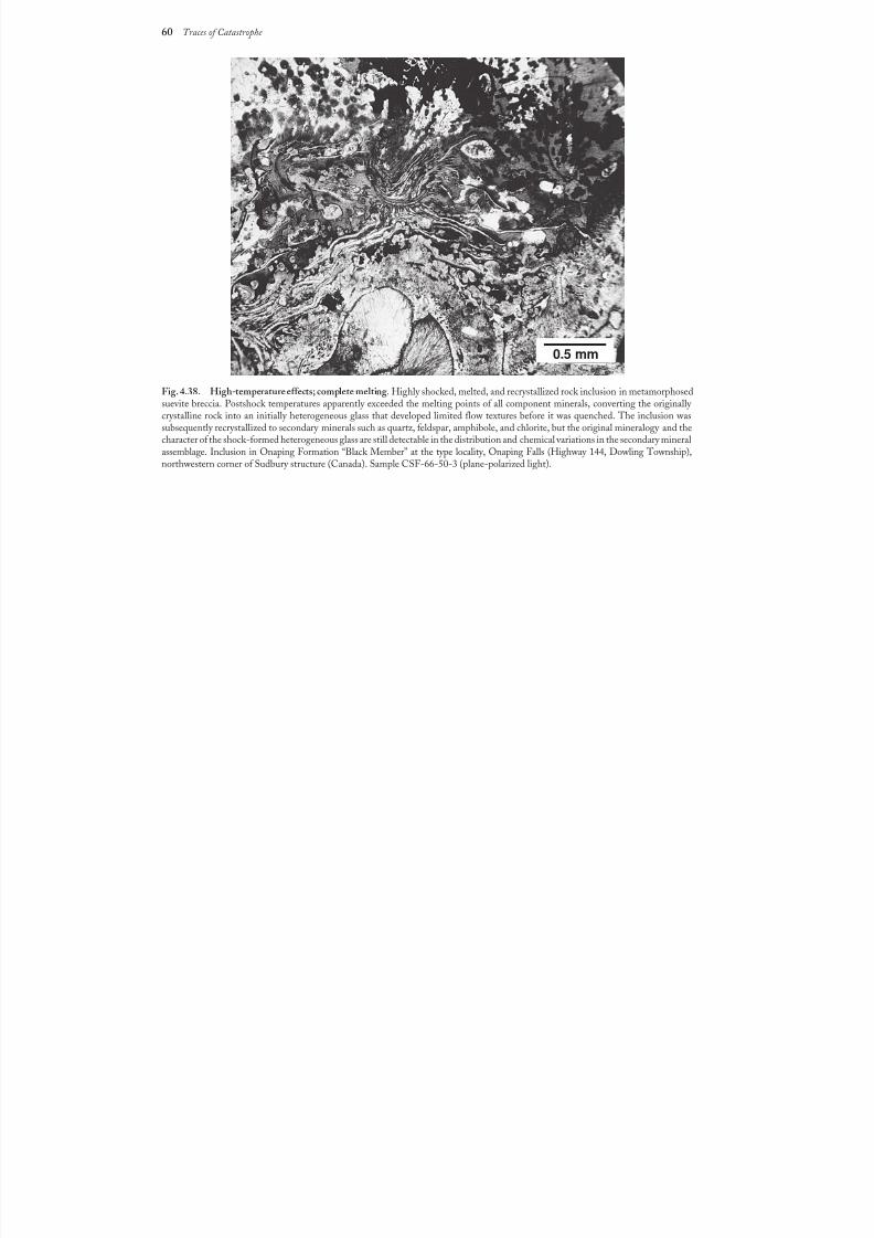
8/8/2019 Traces of Catastrophe - Book
http://slidepdf.com/reader/full/traces-of-catastrophe-book 71/130
60 Traces of Catastrophe
Fig. 4.38. High-temperature effects; complete melting. Highly shocked, melted, and recrystallized rock inclusion in metamorphosedsuevite breccia. Postshock temperatures apparently exceeded the melting points of all component minerals, converting the originally crystalline rock into an initially heterogeneous glass that developed limited flow textures before it was quenched. The inclusion wassubsequently recrystallized to secondary minerals such as quartz, feldspar, amphibole, and chlorite, but the original mineralogy and thecharacter of the shock-formed heterogeneous glass are still detectable in the distribution and chemical variations in the secondary mineralassemblage. Inclusion in Onaping Formation “Black Member” at the type locality, Onaping Falls (Highway 144, Dowling Township),northwestern corner of Sudbury structure (Canada). Sample CSF-66-50-3 (plane-polarized light).
0.5 mm
8/8/2019 Traces of Catastrophe - Book
http://slidepdf.com/reader/full/traces-of-catastrophe-book 72/130
Shock-Metamorphosed Rocks (Impactites) in Impact Structures 61
61
5.1. ROCK TYPES IN THE FINALIMPACT STRUCTURE
A wide variety of distinctive rock types — breccias, melts,and shock-metamorphosed target rocks — are producedduring formation of impact structures. The classificationof these complex and diverse rocks is an active and much-debated activity (see below). However, the general termimpactite is used here as a convenient overall designationfor all rocks affected by, or produced by, the shock wavesand other processes generated by hypervelocity meteorite
impact events.Different varieties of impactites are produced at different
times during the impact process, and they occur in differentlocations beneath, within, and around the final impact struc-ture. The diverse features of impactites reflect, in varying
ways, different aspects of the impact event itself: (1) theinitial shock-wave distribution around the impact point;(2) the subsequent excavation flow, formation of the tran-sient crater, and ejection of material from it; (3) the cratermodification processes. The general model described below
will be modified, in actual impact structures, by such indi- vidual factors as the target lithology, stratigraphy, and thenature and impact angle of the projectile, but the model pro-
vides a general basis for the identification and classificationof impactites (see also Dence, 1968; Grieve, 1991; Stöffler et al., 1988).
The basic distribution of shock-wave pressures aroundthe impact point is largely established by the end of the con-tact/compression stage. The expanding shock waves depositenergy continuously in the target rocks through which they pass, and both their peak pressures and the resulting post-shock temperatures drop rapidly with distance from the im-pact point. As the contact/compression stage ends, and thetransient crater begins to form, the zones of shock pressure
form a series of approximately hemispherical shells aroundthe impact point, with the peak shock pressure decreasingrapidly outward (Fig. 3.2).
During the subsequent excavation stage and formationof the transient crater, virtually all the target rock exposed toshock pressures of >25–30 GPa, which now consists of amixture of vapor, superheated rock melt, and coherent buthighly shocked target rock, is broken up and acceleratedoutward (Dence, 1968; Dence et al., 1977; Grieve and Cintala,1981). Because the excavation flow lines cut across the origi-nally hemispherical shock-pressure zones (Fig. 3.4), the ex-
cavated material will consist of a mixture of target rockssubjected to widely differing shock pressures and showing a
wide range of shock effects. A melt-rich portion flows down- ward and outward from the center to form a coating alongthe floor and walls of the growing crater (Grieve et al., 1977).
The remainder, a mixture of rock fragments and smaller bod-ies of melt, is impelled outward from the center of the cavity.Much of this material may be entirely ejected from the tran-sient crater; some may remain within the crater as a unit of mixed rubble and melt above the fractured crater floor.
The subcrater rocks beneath the zone of excavation aresubjected to lower shock pressures ( >30 GPa), and the domi-nant effects produced are shatter cones, brecciation, and in-
place fracturing. As the upper part of the target rocks areexcavated from the transient crater, these rocks are displaceddownward, more or less coherently, to form the floor of thetransient crater and the zone of parautochthonous rocksbeneath it.
The final modification of the transient crater into a simpleor complex impact structure involves several distinct grav-ity-related processes that influence the distribution of impactite units: (1) rapid relative movements of large blocksof subcrater target rocks downward, inward, and upwardalong relatively narrow faults; (2) collapse of oversteepened
Shock-Metamorphosed Rocks (Impactites)in Impact Structures
8/8/2019 Traces of Catastrophe - Book
http://slidepdf.com/reader/full/traces-of-catastrophe-book 73/130
62 Traces of Catastrophe
crater walls into the crater cavity; (3) deposition of a minoramount of ejected material within the crater. The first pro-cess may create additional breccias and related rock typesbeneath the crater. The other two processes produce a largeportion of the crater-fill deposits, which are characterizedby a generally fragmental character and the presence of shock-metamorphic effects that range from simple fracturing tocomplete melting.
5.2. CLASSIFICATION OF IMPACTITES
The definition and classification of impact-producedmaterials, both individual rock fragments and large forma-tions, is a complex, longstanding, and difficult subject (fordetails, see Stöffler, 1971; Stöffler et al., 1979; Taylor et al.,1991; Stöffler and Grieve, 1994, 1996; Reimold, 1995). Noattempt will be made here to develop a complete and unani-mously acceptable system. The simplified system presentedhere emphasizes field and petrologic characteristics and isbased, as far as possible, on objective features that are ob-servable in outcrop, hand specimen, and thin section. Thisclassification also uses, as much as possible, traditional termsalready applied to equivalent rocks (e.g., breccias, melt rocks)formed by common geological processes. Although this sys-tem is generally consistent with more detailed classifications(e.g., Stöffler and Grieve, 1994), it is restricted to terrestrialrock types produced in single impact events and does notconsider the special complexities of cratering on other plan-ets, including the effects of multiple impacts or the absenceof an atmosphere (see Taylor et al., 1991; Stöffler and Grieve,1994, 1996).
The term impactite is used here to designate all rocks
produced during an impact event, including shock-meta-morphosed (but still recognizable) target rocks (both in placeand as fragments in breccias), breccias, and impact melts.Under this umbrella, the classification and terminology of impactite formations are based on a few key features: location
with respect to the crater, source(s) of component materials,and lithologic characteristics (Table 5.1).
More detailed discriminators, used in other classifications,include (1) particle sizes and size ranges; (2) relative per-centages of components in breccias, e.g., ratios of fragments/matrix, and lithic/glassy fragments; (3) shock-metamorphiceffects in individual breccia fragments (both the shock levelin individual fragments and the range of shock effects in
multiple fragments); and (4) textures and crystallinity of melt rocks.
In earlier discussions of impactites and the cratering pro-cess (Dence, 1965, 1968; Grieve, 1991), a fundamental anduseful distinction has been made between the parautoch-thonous rocks beneath the crater floor and the allogenic (orallochthonous) units (breccias and melt rocks) that fill thecrater (crater-fill units) and form the units of ejecta outsideit (Figs. 3.7 and 3.13). The observed characteristics of thesedifferent rock types are frequently distinctive enough that
they can be distinguished, even in isolated hand specimensor outcrops.
The parautochthonous rocks beneath the crater haveremained relatively coherent during crater formation, al-though they have been deformed and displaced. These rocks,
which correspond to the lower displaced zone of the tran-sient crater, are subjected to relatively lower shock pres-sures, and observed shock-deformation effects are generally
limited to fracturing, brecciation, and the formation of shat-ter cones, although higher-pressure mineral-deformationfeatures may be developed in a relatively small volume be-neath the crater floor. The allogenic rocks, chiefly brecciasand melts, that fill the crater and make up the ejecta beyondthe crater rim, are characterized by a more diverse lithol-ogy, a fragmental or melted character, and a wide rangeof observed shock effects. In particular, the crater-fill brec-cias are a complex mixture of materials with different histo-ries of shock pressures and transport: unshocked rocksderived from the distant parts of the crater rim and walls,more highly shocked and melted fragments excavated fromthe transient crater and redeposited, and large and smallbodies of impact-generated melt.
The following sections discuss impactites on the basis of location with respect to the impact structure: (1)sub-crater: parautochthonous rocks, cross-cutting allogenicunits, and pseudotachylite; (2) crater interior: allogeniccrater-fill deposits (lithic breccias, suevite breccias, and im-pact melt breccias); (3) crater rim region: proximal ejectadeposits; (4) distant from crater: distal ejecta. A detaileddiscussion of impact melt rocks in these different environ-ments is provided in Chapter 7.
5.3. SUBCRATER ROCKS
5.3.1. Formation ConditionsDuring formation of the transient crater, the rocks lo-
cated in the displaced zone below the zone of excavation aredriven downward and outward, more or less coherently (Fig.3.4), but they are not completely broken up or exca-
vated. Instead, they are deformed, thinned, and moved down- ward and outward as the transient crater forms, and then (inthe central parts of larger structures) rapidly elevated as thecentral uplift forms (Dence, 1968; Dence et al., 1977; Kieffer and Simonds, 1980; Grieve and Cintala, 1981; Grieve et al.,1981; Stöffler et al., 1988).
During these movements, the subcrater rocks are gener-ally displaced as large individual blocks typically tens to hun-dreds of meters (or even larger) in size. However, adjacentregions within this zone may display little displacement rela-tive to each other, and original stratigraphy and structuralfeatures may be well preserved within individual blocks. Theterm parautochthonous has therefore been applied to theserocks to indicate their general relative coherence.
The shock pressures imposed on the parautochthonousrocks vary widely because of the complex relationship be-
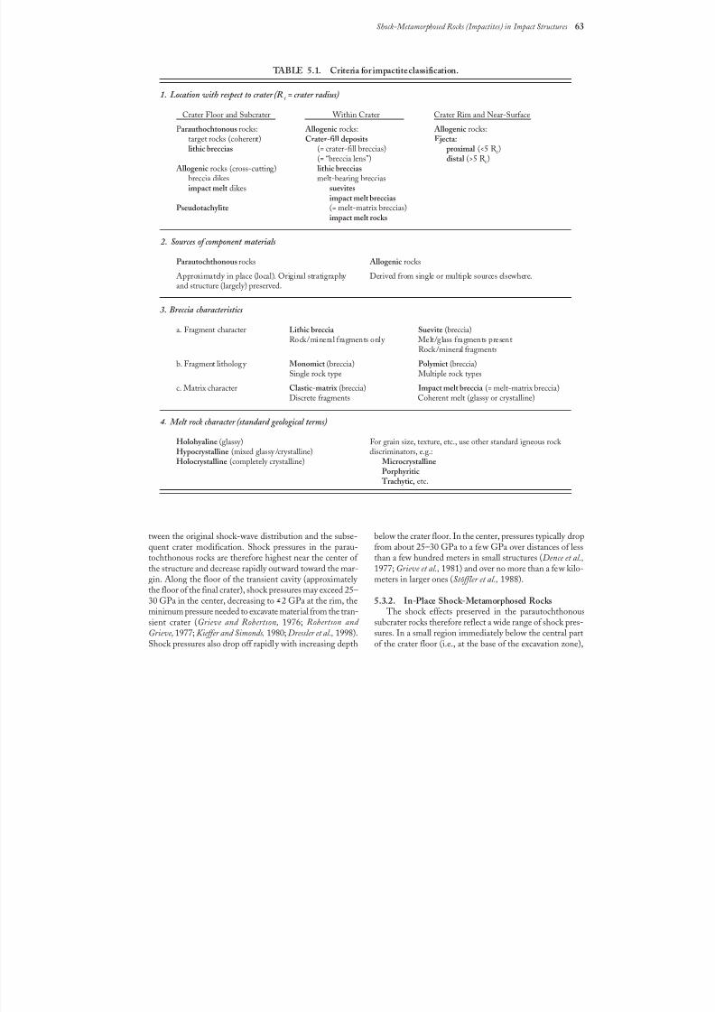
8/8/2019 Traces of Catastrophe - Book
http://slidepdf.com/reader/full/traces-of-catastrophe-book 74/130
Shock-Metamorphosed Rocks (Impactites) in Impact Structures 63
tween the original shock-wave distribution and the subse-
quent crater modification. Shock pressures in the parau-tochthonous rocks are therefore highest near the center of the structure and decrease rapidly outward toward the mar-gin. Along the floor of the transient cavity (approximately the floor of the final crater), shock pressures may exceed 25–30 GPa in the center, decreasing to >2 GPa at the rim, theminimum pressure needed to excavate material from the tran-sient crater (Grieve and Robertson, 1976; Robertson and Grieve, 1977; Kieffer and Simonds, 1980; Dressler et al., 1998).Shock pressures also drop off rapidly with increasing depth
below the crater floor. In the center, pressures typically drop
from about 25–30 GPa to a few GPa over distances of lessthan a few hundred meters in small structures (Dence et al.,1977; Grieve et al., 1981) and over no more than a few kilo-meters in larger ones (Stöffler et al., 1988).
5.3.2. In-Place Shock-Metamorphosed Rocks The shock effects preserved in the parautochthonous
subcrater rocks therefore reflect a wide range of shock pres-sures. In a small region immediately below the central partof the crater floor (i.e., at the base of the excavation zone),
TABLE 5.1. Criteria for impactite classification.
1. Location with respect to crater (Rc = crater radius)
Crater Floor and Subcrater Within Crater Crater Rim and Near-Surface
Parauthochtonous rocks: Allogenic rocks: Allogenic rocks:
target rocks (coherent) Crater-fill deposits Ejecta:lithic breccias (= crater-fill breccias) proximal (<5 R c)
(= “breccia lens”) distal (>5 R c) Allogenic rocks (cross-cutting) lithic breccias
breccia dikes melt-bearing brecciasimpact melt dikes suevites
impact melt brecciasPseudotachylite (= melt-matrix breccias)
impact melt rocks
2. Sources of component materials
Parautochthonous rocks Allogenic rocks
Approximately in place (local). Original stratigraphy Derived from single or multiple sources elsewhere.and structure (largely) preserved.
3. Breccia characteristics
a. Fragment character Lithic breccia Suevite (breccia)Rock/mineral fragments only Melt/glass fragments present
Rock/mineral fragments
b. Fragment lithology Monomict (breccia) Polymict (breccia)Single rock type Multiple rock types
c. Matrix character Clastic-matrix (breccia) Impact melt breccia (= melt-matrix breccia)Discrete fragments Coherent melt (glassy or crystalline)
4. Melt rock character (standard geological terms)
Holohyaline (glassy) For grain size, texture, etc., use other standard igneous rock Hypocrystalline (mixed glassy /crystalline) discriminators, e.g.:Holocrystalline (completely crystalline) Microcrystalline
Porphyritic Trachytic, etc.
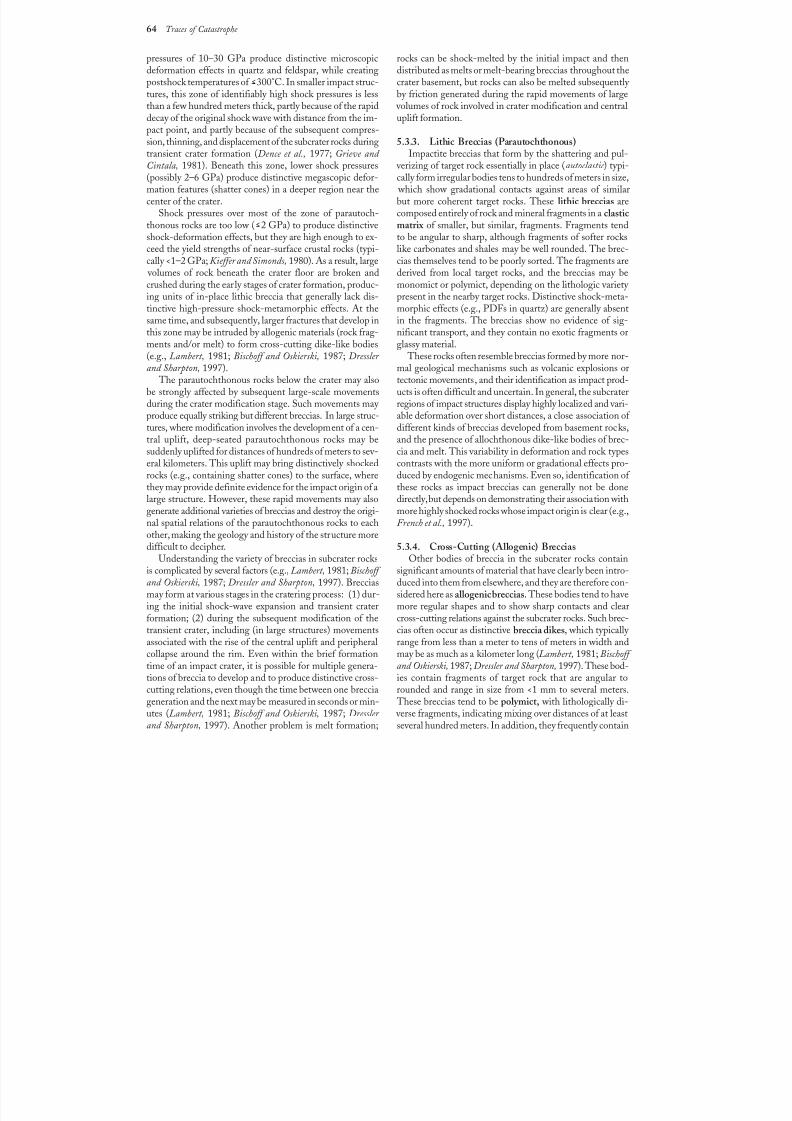
8/8/2019 Traces of Catastrophe - Book
http://slidepdf.com/reader/full/traces-of-catastrophe-book 75/130
64 Traces of Catastrophe
pressures of 10–30 GPa produce distinctive microscopicdeformation effects in quartz and feldspar, while creatingpostshock temperatures of >300°C. In smaller impact struc-tures, this zone of identifiably high shock pressures is lessthan a few hundred meters thick, partly because of the rapiddecay of the original shock wave with distance from the im-pact point, and partly because of the subsequent compres-sion, thinning, and displacement of the subcrater rocks during
transient crater formation (Dence et al., 1977; Grieve and Cintala, 1981). Beneath this zone, lower shock pressures(possibly 2–6 GPa) produce distinctive megascopic defor-mation features (shatter cones) in a deeper region near thecenter of the crater.
Shock pressures over most of the zone of parautoch-thonous rocks are too low ( >2 GPa) to produce distinctiveshock-deformation effects, but they are high enough to ex-ceed the yield strengths of near-surface crustal rocks (typi-cally <1–2 GPa; Kieffer and Simonds, 1980). As a result, large
volumes of rock beneath the crater floor are broken andcrushed during the early stages of crater formation, produc-ing units of in-place lithic breccia that generally lack dis-tinctive high-pressure shock-metamorphic effects. At thesame time, and subsequently, larger fractures that develop inthis zone may be intruded by allogenic materials (rock frag-ments and/or melt) to form cross-cutting dike-like bodies(e.g., Lambert, 1981; Bischoff and Oskierski, 1987; Dressler and Sharpton, 1997).
The parautochthonous rocks below the crater may alsobe strongly affected by subsequent large-scale movementsduring the crater modification stage. Such movements may produce equally striking but different breccias. In large struc-tures, where modification involves the development of a cen-tral uplift, deep-seated parautochthonous rocks may be
suddenly uplifted for distances of hundreds of meters to sev-eral kilometers. This uplift may bring distinctively shockedrocks (e.g., containing shatter cones) to the surface, wherethey may provide definite evidence for the impact origin of alarge structure. However, these rapid movements may alsogenerate additional varieties of breccias and destroy the origi-nal spatial relations of the parautochthonous rocks to eachother, making the geology and history of the structure moredifficult to decipher.
Understanding the variety of breccias in subcrater rocksis complicated by several factors (e.g., Lambert, 1981; Bischoff and Oskierski, 1987; Dressler and Sharpton, 1997). Brecciasmay form at various stages in the cratering process: (1) dur-
ing the initial shock-wave expansion and transient craterformation; (2) during the subsequent modification of thetransient crater, including (in large structures) movementsassociated with the rise of the central uplift and peripheralcollapse around the rim. Even within the brief formationtime of an impact crater, it is possible for multiple genera-tions of breccia to develop and to produce distinctive cross-cutting relations, even though the time between one brecciageneration and the next may be measured in seconds or min-utes (Lambert, 1981; Bischoff and Oskierski, 1987; Dressler and Sharpton, 1997). Another problem is melt formation;
rocks can be shock-melted by the initial impact and thendistributed as melts or melt-bearing breccias throughout thecrater basement, but rocks can also be melted subsequently by friction generated during the rapid movements of large
volumes of rock involved in crater modification and centraluplift formation.
5.3.3. Lithic Breccias (Parautochthonous)
Impactite breccias that form by the shattering and pul- verizing of target rock essentially in place (autoclastic ) typi-cally form irregular bodies tens to hundreds of meters in size,
which show gradational contacts against areas of similarbut more coherent target rocks. These lithic breccias arecomposed entirely of rock and mineral fragments in a clasticmatrix of smaller, but similar, fragments. Fragments tendto be angular to sharp, although fragments of softer rockslike carbonates and shales may be well rounded. The brec-cias themselves tend to be poorly sorted. The fragments arederived from local target rocks, and the breccias may bemonomict or polymict, depending on the lithologic variety present in the nearby target rocks. Distinctive shock-meta-morphic effects (e.g., PDFs in quartz) are generally absentin the fragments. The breccias show no evidence of sig-nificant transport, and they contain no exotic fragments orglassy material.
These rocks often resemble breccias formed by more nor-mal geological mechanisms such as volcanic explosions ortectonic movements, and their identification as impact prod-ucts is often difficult and uncertain. In general, the subcraterregions of impact structures display highly localized and vari-able deformation over short distances, a close association of different kinds of breccias developed from basement rocks,and the presence of allochthonous dike-like bodies of brec-
cia and melt. This variability in deformation and rock typescontrasts with the more uniform or gradational effects pro-duced by endogenic mechanisms. Even so, identification of these rocks as impact breccias can generally not be donedirectly, but depends on demonstrating their association withmore highly shocked rocks whose impact origin is clear (e.g.,French et al., 1997).
5.3.4. Cross-Cutting (Allogenic) BrecciasOther bodies of breccia in the subcrater rocks contain
significant amounts of material that have clearly been intro-duced into them from elsewhere, and they are therefore con-sidered here as allogenic breccias. These bodies tend to have
more regular shapes and to show sharp contacts and clearcross-cutting relations against the subcrater rocks. Such brec-cias often occur as distinctive breccia dikes, which typically range from less than a meter to tens of meters in width andmay be as much as a kilometer long (Lambert, 1981; Bischoff and Oskierski, 1987; Dressler and Sharpton, 1997). These bod-ies contain fragments of target rock that are angular torounded and range in size from <1 mm to several meters.
These breccias tend to be polymict, with lithologically di- verse fragments, indicating mixing over distances of at leastseveral hundred meters. In addition, they frequently contain
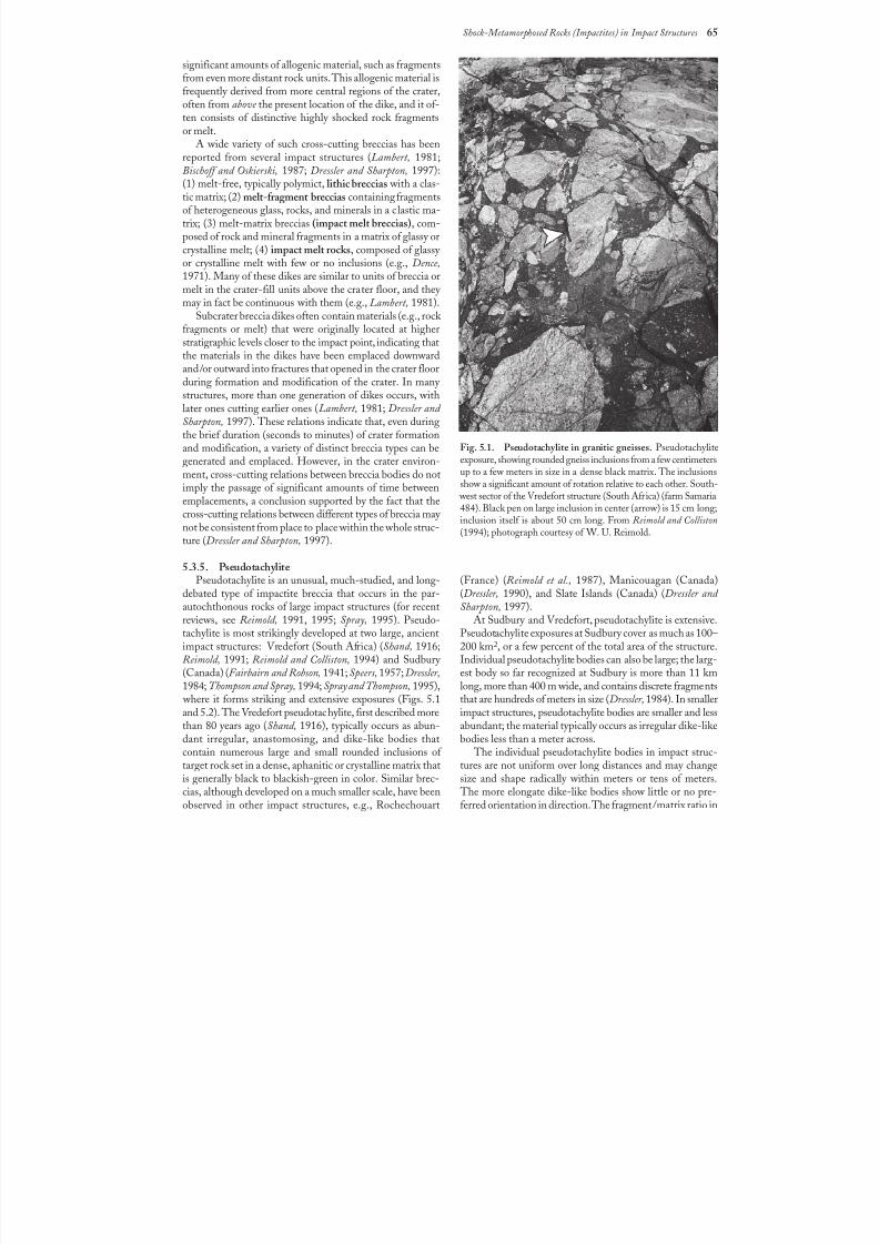
8/8/2019 Traces of Catastrophe - Book
http://slidepdf.com/reader/full/traces-of-catastrophe-book 76/130
Shock-Metamorphosed Rocks (Impactites) in Impact Structures 65
significant amounts of allogenic material, such as fragmentsfrom even more distant rock units. This allogenic material isfrequently derived from more central regions of the crater,often from above the present location of the dike, and it of-ten consists of distinctive highly shocked rock fragmentsor melt.
A wide variety of such cross-cutting breccias has beenreported from several impact structures (Lambert, 1981;
Bischoff and Oskierski, 1987; Dressler and Sharpton, 1997):(1) melt-free, typically polymict, lithic breccias with a clas-tic matrix; (2) melt-fragment breccias containing fragmentsof heterogeneous glass, rocks, and minerals in a clastic ma-trix; (3) melt-matrix breccias (impact melt breccias), com-posed of rock and mineral fragments in a matrix of glassy orcrystalline melt; (4) impact melt rocks, composed of glassy or crystalline melt with few or no inclusions (e.g., Dence,1971). Many of these dikes are similar to units of breccia ormelt in the crater-fill units above the crater floor, and they may in fact be continuous with them (e.g., Lambert, 1981).
Subcrater breccia dikes often contain materials (e.g., rock fragments or melt) that were originally located at higherstratigraphic levels closer to the impact point, indicating thatthe materials in the dikes have been emplaced downwardand/or outward into fractures that opened in the crater floorduring formation and modification of the crater. In many structures, more than one generation of dikes occurs, withlater ones cutting earlier ones (Lambert, 1981; Dressler and Sharpton, 1997). These relations indicate that, even duringthe brief duration (seconds to minutes) of crater formationand modification, a variety of distinct breccia types can begenerated and emplaced. However, in the crater environ-ment, cross-cutting relations between breccia bodies do notimply the passage of significant amounts of time between
emplacements, a conclusion supported by the fact that thecross-cutting relations between different types of breccia may not be consistent from place to place within the whole struc-ture (Dressler and Sharpton, 1997).
5.3.5. PseudotachylitePseudotachylite is an unusual, much-studied, and long-
debated type of impactite breccia that occurs in the par-autochthonous rocks of large impact structures (for recentreviews, see Reimold, 1991, 1995; Spray, 1995). Pseudo-tachylite is most strikingly developed at two large, ancientimpact structures: Vredefort (South Africa) (Shand, 1916;Reimold, 1991; Reimold and Colliston, 1994) and Sudbury
(Canada) (Fairbairn and Robson, 1941; Speers, 1957;Dressler,1984; Thompson and Spray, 1994; Spray and Thompson, 1995),
where it forms striking and extensive exposures (Figs. 5.1and 5.2). The Vredefort pseudotachylite, first described morethan 80 years ago (Shand, 1916), typically occurs as abun-dant irregular, anastomosing, and dike-like bodies thatcontain numerous large and small rounded inclusions of target rock set in a dense, aphanitic or crystalline matrix thatis generally black to blackish-green in color. Similar brec-cias, although developed on a much smaller scale, have beenobserved in other impact structures, e.g., Rochechouart
(France) (Reimold et al., 1987), Manicouagan (Canada)(Dressler, 1990), and Slate Islands (Canada) (Dressler and Sharpton, 1997).
At Sudbury and Vredefort, pseudotachylite is extensive.Pseudotachylite exposures at Sudbury cover as much as 100–200 km2, or a few percent of the total area of the structure.Individual pseudotachylite bodies can also be large; the larg-
est body so far recognized at Sudbury is more than 11 kmlong, more than 400 m wide, and contains discrete fragmentsthat are hundreds of meters in size (Dressler,1984). In smallerimpact structures, pseudotachylite bodies are smaller and lessabundant; the material typically occurs as irregular dike-likebodies less than a meter across.
The individual pseudotachylite bodies in impact struc-tures are not uniform over long distances and may changesize and shape radically within meters or tens of meters.
The more elongate dike-like bodies show little or no pre-ferred orientation in direction. The fragment/matrix ratio in
Fig.5.1. Pseudotachylite in granitic gneisses. Pseudotachyliteexposure, showing rounded gneiss inclusions from a few centimetersup to a few meters in size in a dense black matrix. The inclusionsshow a significant amount of rotation relative to each other. South-
west sector of the Vredefort structure (South Africa) (farm Samaria
484). Black pen on large inclusion in center (arrow) is 15 cm long;inclusion itself is about 50 cm long. From Reimold and Colliston(1994); photograph courtesy of W. U. Reimold.
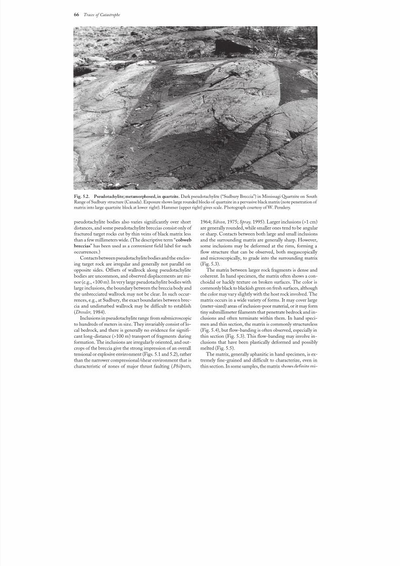
8/8/2019 Traces of Catastrophe - Book
http://slidepdf.com/reader/full/traces-of-catastrophe-book 77/130
66 Traces of Catastrophe
pseudotachylite bodies also varies significantly over short
distances, and some pseudotachylite breccias consist only of fractured target rocks cut by thin veins of black matrix lessthan a few millimeters wide. (The descriptive term “cobwebbreccias” has been used as a convenient field label for suchoccurrences.)
Contacts between pseudotachylite bodies and the enclos-ing target rock are irregular and generally not parallel onopposite sides. Offsets of wallrock along pseudotachylitebodies are uncommon, and observed displacements are mi-nor (e.g., <100 m). In very large pseudotachylite bodies withlarge inclusions, the boundary between the breccia body andthe unbrecciated wallrock may not be clear. In such occur-rences, e.g., at Sudbury, the exact boundaries between brec-
cia and undisturbed wallrock may be difficult to establish(Dressler, 1984).
Inclusions in pseudotachylite range from submicroscopicto hundreds of meters in size. They invariably consist of lo-cal bedrock, and there is generally no evidence for signifi-cant long-distance (>100 m) transport of fragments duringformation. The inclusions are irregularly oriented, and out-crops of the breccia give the strong impression of an overalltensional or explosive environment (Figs. 5.1 and 5.2), ratherthan the narrower compressional /shear environment that ischaracteristic of zones of major thrust faulting (Philpotts,
1964; Sibson, 1975; Spray, 1995). Larger inclusions (>1 cm)
are generally rounded, while smaller ones tend to be angularor sharp. Contacts between both large and small inclusionsand the surrounding matrix are generally sharp. However,some inclusions may be deformed at the rims, forming aflow structure that can be observed, both megascopically and microscopically, to grade into the surrounding matrix(Fig. 5.3).
The matrix between larger rock fragments is dense andcoherent. In hand specimen, the matrix often shows a con-choidal or hackly texture on broken surfaces. The color iscommonly black to blackish green on fresh surfaces, althoughthe color may vary slightly with the host rock involved. Thematrix occurs in a wide variety of forms. It may cover large
(meter-sized) areas of inclusion-poor material, or it may formtiny submillimeter filaments that penetrate bedrock and in-clusions and often terminate within them. In hand speci-men and thin section, the matrix is commonly structureless(Fig. 5.4), but flow-banding is often observed, especially inthin section (Fig. 5.3). This flow-banding may involve in-clusions that have been plastically deformed and possibly melted (Fig. 5.5).
The matrix, generally aphanitic in hand specimen, is ex-tremely fine-grained and difficult to characterize, even inthin section. In some samples, the matrix shows definite mi-
Fig.5.2. Pseudotachylite; metamorphosed, in quartzite. Dark pseudotachylite (“Sudbury Breccia”) in Mississagi Quartzite on SouthRange of Sudbury structure (Canada). Exposure shows large rounded blocks of quartzite in a pervasive black matrix (note penetration of matrix into large quartzite block at lower right). Hammer (upper right) gives scale. Photograph courtesy of W. Peredery.
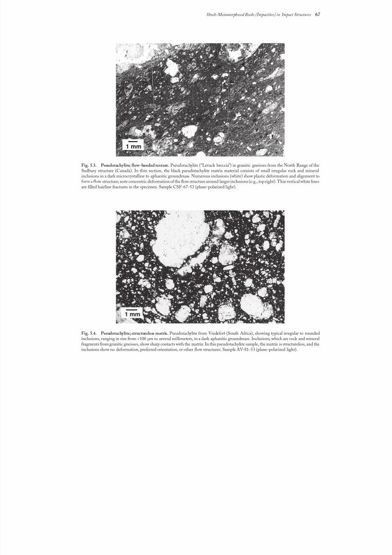
8/8/2019 Traces of Catastrophe - Book
http://slidepdf.com/reader/full/traces-of-catastrophe-book 78/130
Shock-Metamorphosed Rocks (Impactites) in Impact Structures 67
Fig.5.3. Pseudotachylite; flow-banded texture. Pseudotachylite (“Levack breccia”) in granitic gneisses from the North Range of theSudbury structure (Canada). In thin section, the black pseudotachylite matrix material consists of small irregular rock and mineralinclusions in a dark microcrystalline to aphanitic groundmass. Numerous inclusions (white) show plastic deformation and alignment toform a flow structure; note concentric deformation of the flow structure around larger inclusions (e.g., top right). Thin vertical white linesare filled hairline fractures in the specimen. Sample CSF-67-53 (plane-polarized light).
Fig.5.4. Pseudotachylite; structureless matrix. Pseudotachylite from Vredefort (South Africa), showing typical irregular to roundedinclusions, ranging in size from <100 µm to several millimeters, in a dark aphanitic groundmass. Inclusions, which are rock and mineralfragments from granitic gneisses, show sharp contacts with the matrix. In this pseudotachylite sample, the matrix is structureless, and theinclusions show no deformation, preferred orientation, or other flow structures. Sample AV-81-53 (plane-polarized light).
1 mm
1 mm
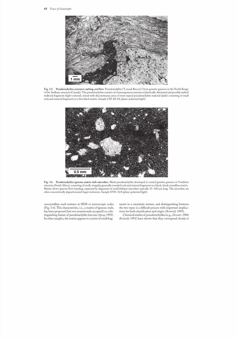
8/8/2019 Traces of Catastrophe - Book
http://slidepdf.com/reader/full/traces-of-catastrophe-book 79/130
68 Traces of Catastrophe
crocrystalline melt textures at SEM or microscopic scales(Fig. 5.6). This characteristic, i.e., a matrix of igneous melt,has been proposed (but not unanimously accepted) as a dis-tinguishing feature of pseudotachylite breccias (Spray, 1995).In other samples, the matrix appears to consist of small frag-
ments in a cataclastic texture, and distinguishing betweenthe two types is a difficult process with important implica-tions for both classification and origin (Reimold, 1995).
Chemical studies of pseudotachylites (e.g., Dressler, 1984;Reimold, 1991) have shown that they correspond closely to
Fig.5.5. Pseudotachylite; extensive melting and flow. Pseudotachylite (“Levack Breccia”) from granitic gneisses in the North Range
of the Sudbury structure (Canada). The pseudotachylite consists of a heterogeneous mixture of plastically deformed and possibly melted wallrock fragments (light-colored), mixed with discontinuous areas of more typical pseudotachylite material (dark) consisting of smallrock and mineral fragments in a fine black matrix. Sample CSF-88-2A (plane-polarized light).
Fig.5.6. Pseudotachylite; igneous matrix with microlites. Black pseudotachylite developed in central granitic gneisses at Vredefortstructure (South Africa), consisting of small, irregular, generally rounded rock and mineral fragments in a black, finely crystalline matrix.Matrix shows igneous flow-banding, expressed by alignment of small feldspar microlites typically 50–100µm long. The microlites areoften concentrically aligned around larger inclusions. Sample AV81-52A (plane-polarized light).
1 mm
0.5 mm
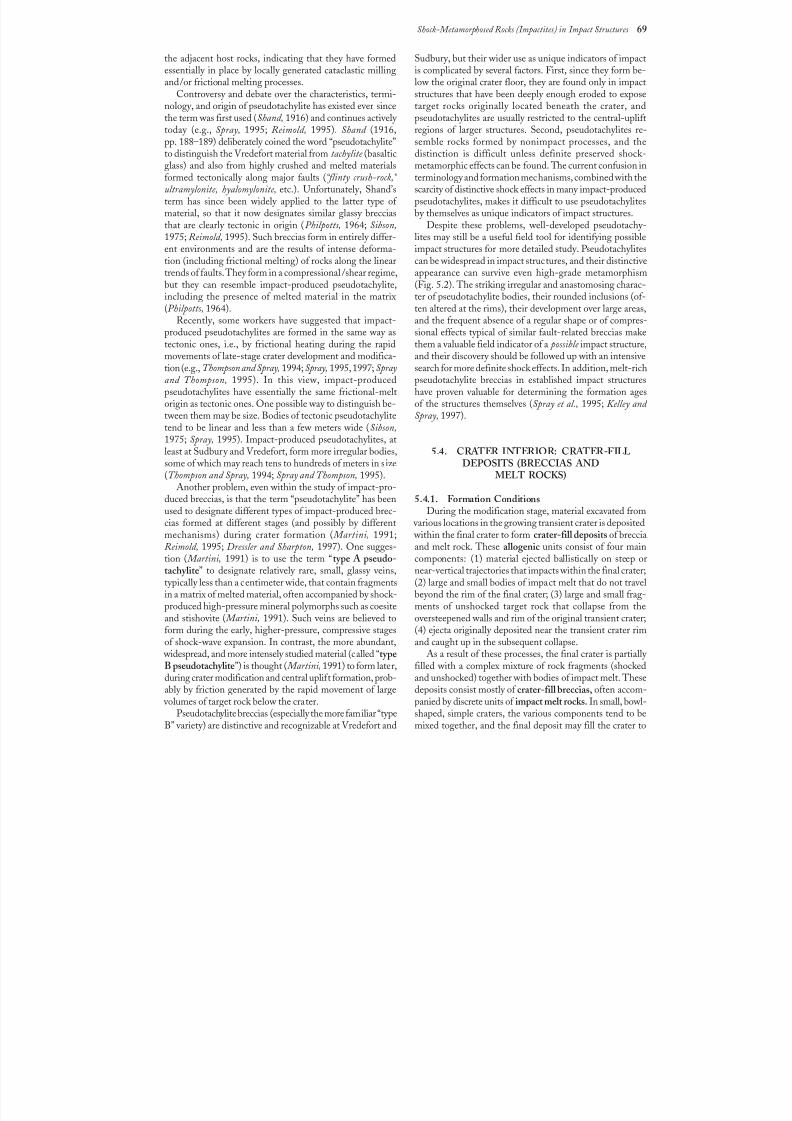
8/8/2019 Traces of Catastrophe - Book
http://slidepdf.com/reader/full/traces-of-catastrophe-book 80/130
Shock-Metamorphosed Rocks (Impactites) in Impact Structures 69
the adjacent host rocks, indicating that they have formedessentially in place by locally generated cataclastic millingand/or frictional melting processes.
Controversy and debate over the characteristics, termi-nology, and origin of pseudotachylite has existed ever sincethe term was first used (Shand, 1916) and continues actively today (e.g., Spray, 1995; Reimold, 1995). Shand (1916,pp.188–189) deliberately coined the word “pseudotachylite”
to distinguish the Vredefort material from tachylite (basalticglass) and also from highly crushed and melted materialsformed tectonically along major faults (“flinty crush-rock,” ultramylonite, hyalomylonite, etc.). Unfortunately, Shand’sterm has since been widely applied to the latter type of material, so that it now designates similar glassy brecciasthat are clearly tectonic in origin (Philpotts, 1964; Sibson,1975; Reimold, 1995). Such breccias form in entirely differ-ent environments and are the results of intense deforma-tion (including frictional melting) of rocks along the lineartrends of faults. They form in a compressional /shear regime,but they can resemble impact-produced pseudotachylite,including the presence of melted material in the matrix(Philpotts, 1964).
Recently, some workers have suggested that impact-produced pseudotachylites are formed in the same way astectonic ones, i.e., by frictional heating during the rapidmovements of late-stage crater development and modifica-tion (e.g., Thompson and Spray, 1994; Spray, 1995, 1997; Sprayand Thompson, 1995). In this view, impact-producedpseudotachylites have essentially the same frictional-meltorigin as tectonic ones. One possible way to distinguish be-tween them may be size. Bodies of tectonic pseudotachylitetend to be linear and less than a few meters wide (Sibson,1975; Spray, 1995). Impact-produced pseudotachylites, at
least at Sudbury and Vredefort, form more irregular bodies,some of which may reach tens to hundreds of meters in size(Thompson and Spray, 1994; Spray and Thompson, 1995).
Another problem, even within the study of impact-pro-duced breccias, is that the term “pseudotachylite” has beenused to designate different types of impact-produced brec-cias formed at different stages (and possibly by differentmechanisms) during crater formation ( Martini, 1991;Reimold, 1995; Dressler and Sharpton, 1997). One sugges-tion ( Martini, 1991) is to use the term “type A pseudo-tachylite” to designate relatively rare, small, glassy veins,typically less than a centimeter wide, that contain fragmentsin a matrix of melted material, often accompanied by shock-
produced high-pressure mineral polymorphs such as coesiteand stishovite ( Martini, 1991). Such veins are believed toform during the early, higher-pressure, compressive stagesof shock-wave expansion. In contrast, the more abundant,
widespread, and more intensely studied material (called “typeB pseudotachylite”) is thought ( Martini, 1991) to form later,during crater modification and central uplift formation, prob-ably by friction generated by the rapid movement of large
volumes of target rock below the crater.Pseudotachylite breccias (especially the more familiar “type
B” variety) are distinctive and recognizable at Vredefort and
Sudbury, but their wider use as unique indicators of impactis complicated by several factors. First, since they form be-low the original crater floor, they are found only in impactstructures that have been deeply enough eroded to exposetarget rocks originally located beneath the crater, andpseudotachylites are usually restricted to the central-upliftregions of larger structures. Second, pseudotachylites re-semble rocks formed by nonimpact processes, and the
distinction is difficult unless definite preserved shock-metamorphic effects can be found. The current confusion interminology and formation mechanisms, combined with thescarcity of distinctive shock effects in many impact-producedpseudotachylites, makes it difficult to use pseudotachylitesby themselves as unique indicators of impact structures.
Despite these problems, well-developed pseudotachy-lites may still be a useful field tool for identifying possibleimpact structures for more detailed study. Pseudotachylitescan be widespread in impact structures, and their distinctiveappearance can survive even high-grade metamorphism(Fig.5.2). The striking irregular and anastomosing charac-ter of pseudotachylite bodies, their rounded inclusions (of-ten altered at the rims), their development over large areas,and the frequent absence of a regular shape or of compres-sional effects typical of similar fault-related breccias makethem a valuable field indicator of a possible impact structure,and their discovery should be followed up with an intensivesearch for more definite shock effects. In addition, melt-richpseudotachylite breccias in established impact structureshave proven valuable for determining the formation agesof the structures themselves (Spray et al., 1995; Kelley and Spray, 1997).
5.4. CRATER INTERIOR: CRATER-FILLDEPOSITS (BRECCIAS ANDMELT ROCKS)
5.4.1. Formation ConditionsDuring the modification stage, material excavated from
various locations in the growing transient crater is deposited within the final crater to form crater-fill deposits of brecciaand melt rock. These allogenic units consist of four maincomponents: (1) material ejected ballistically on steep ornear-vertical trajectories that impacts within the final crater;(2) large and small bodies of impact melt that do not travelbeyond the rim of the final crater; (3) large and small frag-
ments of unshocked target rock that collapse from theoversteepened walls and rim of the original transient crater;(4) ejecta originally deposited near the transient crater rimand caught up in the subsequent collapse.
As a result of these processes, the final crater is partially filled with a complex mixture of rock fragments (shockedand unshocked) together with bodies of impact melt. Thesedeposits consist mostly of crater-fill breccias, often accom-panied by discrete units of impact melt rocks. In small, bowl-shaped, simple craters, the various components tend to bemixed together, and the final deposit may fill the crater to
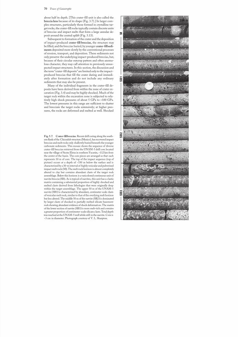
8/8/2019 Traces of Catastrophe - Book
http://slidepdf.com/reader/full/traces-of-catastrophe-book 81/130
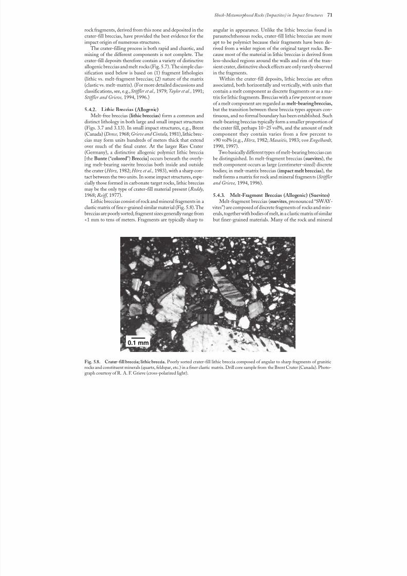
8/8/2019 Traces of Catastrophe - Book
http://slidepdf.com/reader/full/traces-of-catastrophe-book 82/130
Shock-Metamorphosed Rocks (Impactites) in Impact Structures 71
rock fragments, derived from this zone and deposited in thecrater-fill breccias, have provided the best evidence for theimpact origin of numerous structures.
The crater-filling process is both rapid and chaotic, andmixing of the different components is not complete. Thecrater-fill deposits therefore contain a variety of distinctiveallogenic breccias and melt rocks (Fig. 5.7). The simple clas-sification used below is based on (1) fragment lithologies
(lithic vs. melt-fragment breccias; (2) nature of the matrix(clastic vs. melt-matrix). (For more detailed discussions andclassifications, see, e.g.,Stöffler et al., 1979; Taylor et al., 1991;Stöffler and Grieve, 1994, 1996.)
5.4.2. Lithic Breccias (Allogenic)Melt-free breccias (lithic breccias) form a common and
distinct lithology in both large and small impact structures(Figs. 3.7 and 3.13). In small impact structures, e.g., Brent(Canada) (Dence, 1968; Grieve and Cintala, 1981), lithic brec-cias may form units hundreds of meters thick that extendover much of the final crater. At the larger Ries Crater(Germany), a distinctive allogenic polymict lithic breccia[the Bunte (“colored”) Breccia ] occurs beneath the overly-ing melt-bearing suevite breccias both inside and outsidethe crater (Hörz, 1982; Hörz et al., 1983), with a sharp con-tact between the two units. In some impact structures, espe-cially those formed in carbonate target rocks, lithic brecciasmay be the only type of crater-fill material present (Roddy,1968; Reiff, 1977).
Lithic breccias consist of rock and mineral fragments in aclastic matrix of finer-grained similar material (Fig. 5.8). Thebreccias are poorly sorted; fragment sizes generally range from<1 mm to tens of meters. Fragments are typically sharp to
angular in appearance. Unlike the lithic breccias found inparautochthonous rocks, crater-fill lithic breccias are moreapt to be polymict because their fragments have been de-rived from a wider region of the original target rocks. Be-cause most of the material in lithic breccias is derived fromless-shocked regions around the walls and rim of the tran-sient crater, distinctive shock effects are only rarely observedin the fragments.
Within the crater-fill deposits, lithic breccias are oftenassociated, both horizontally and vertically, with units thatcontain a melt component as discrete fragments or as a ma-trix for lithic fragments. Breccias with a few percent or moreof a melt component are regarded as melt-bearing breccias,but the transition between these breccia types appears con-tinuous, and no formal boundary has been established. Suchmelt-bearing breccias typically form a smaller proportion of the crater fill, perhaps 10–25 vol%, and the amount of meltcomponent they contain varies from a few percent to>90vol% (e.g., Hörz, 1982; Masaitis, 1983; von Engelhardt,1990, 1997).
Two basically different types of melt-bearing breccias canbe distinguished. In melt-fragment breccias (suevites), themelt component occurs as large (centimeter-sized) discretebodies; in melt-matrix breccias (impact melt breccias), themelt forms a matrix for rock and mineral fragments (Stöffler and Grieve, 1994, 1996).
5.4.3. Melt-Fragment Breccias (Allogenic) (Suevites)Melt-fragment breccias (suevites, pronounced “SWAY-
vites”) are composed of discrete fragments of rocks and min-erals, together with bodies of melt, in a clastic matrix of similarbut finer-grained materials. Many of the rock and mineral
Fig.5.8. Crater-fill breccia; lithic breccia. Poorly sorted crater-fill lithic breccia composed of angular to sharp fragments of graniticrocks and constituent minerals (quartz, feldspar, etc.) in a finer clastic matrix. Drill core sample from the Brent Crater (Canada). Photo-graph courtesy of R. A. F. Grieve (cross-polarized light).
0.1 mm
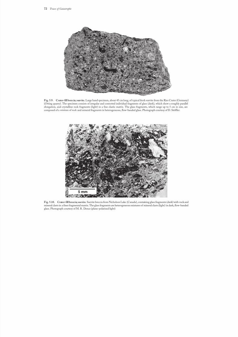
8/8/2019 Traces of Catastrophe - Book
http://slidepdf.com/reader/full/traces-of-catastrophe-book 83/130
72 Traces of Catastrophe
Fig.5.9. Crater-fill breccia; suevite. Large hand specimen, about 45 cm long, of typical fresh suevite from the Ries Crater (Germany)(Otting quarry). The specimen consists of irregular and contorted individual fragments of glass (dark), which show a roughly parallelelongation, and crystalline rock fragments (light) in a fine clastic matrix. The glass fragments, which range up to 5 cm in size, arecomposed of a mixture of rock and mineral fragments in heterogeneous, flow-banded glass. Photograph courtesy of D. Stöffler.
Fig.5.10. Crater-fill breccia; suevite. Suevite breccia from Nicholson Lake (Canada), containing glass fragments (dark) with rock andmineral clasts in a finer fragmental matrix. The glass fragments are heterogeneous mixtures of mineral clasts (light) in dark, flow-bandedglass. Photograph courtesy of M. R. Dence (plane-polarized light).
5 mm
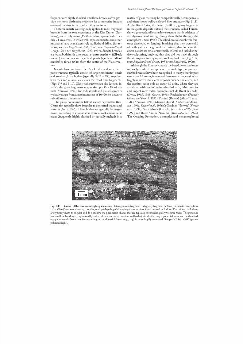
8/8/2019 Traces of Catastrophe - Book
http://slidepdf.com/reader/full/traces-of-catastrophe-book 84/130
Shock-Metamorphosed Rocks (Impactites) in Impact Structures 73
fragments are highly shocked, and these breccias often pro- vide the most distinctive evidence for a meteorite impactorigin of the structures in which they are found.
The term suevite was originally applied to melt-fragmentbreccias from the type occurrence at the Ries Crater (Ger-many), a relatively young (15 Ma) and well-preserved struc-ture 24km across, in which well-exposed suevites and otherimpactites have been extensively studied and drilled (for re-
views, see von Engelhardt et al., 1969; von Engelhardt and Graup, 1984; von Engelhardt, 1990, 1997). Suevite brecciasare found both inside the structure (crater suevite or fallback suevite) and as preserved ejecta deposits (ejecta or fallout suevite) as far as 40 km from the center of the Ries struc-ture.
Suevite breccias from the Ries Crater and other im-pact structures typically consist of large (centimeter-sized)and smaller glassy bodies (typically 5–15 vol%), together
with rock and mineral clasts in a matrix of finer fragments(Figs. 5.9 and 5.10). Glass-rich suevites are also known, in
which the glass fragments may make up >50 vol% of therock ( Masaitis, 1994). Individual rock and glass fragmentstypically range from a maximum size of 10–20 cm down tosubmillimeter dimensions.
The glassy bodies in the fallout suevite beyond the RiesCrater rim typically show irregular to contorted shapes andtextures (Hörz, 1965). These bodies are typically heteroge-neous, consisting of a polymict mixture of rock and mineralclasts (frequently highly shocked or partially melted) in a
matrix of glass that may be compositionally heterogeneousand often shows well-developed flow structure (Fig. 5.11).At the Ries Crater, the larger (5–20 cm) glassy fragmentsin the ejecta deposits outside the structure, called Fladen,show a grooved and lobate flow structure that is evidence of aerodynamic sculpturing during their flight through theatmosphere (Hörz, 1965). These bodies also show brittle frac-tures developed on landing, implying that they were solid
when they struck the ground. In contrast, glass bodies in thecrater suevite are smaller (normally <5 cm) and lack distinc-tive sculpturing, implying that they did not travel throughthe atmosphere for any significant length of time (Fig. 5.12)(vonEngelhardt and Graup, 1984; von Engelhardt, 1990).
Although the Ries suevites are the best-known and mostintensely studied examples of this rock type, impressivesuevite breccias have been recognized in many other impactstructures. However, in many of these structures, erosion haslargely removed the ejecta deposits outside the crater, andthe suevites occur only as crater-fill units, where they areassociated with, and often interbedded with, lithic brecciasand impact-melt rocks. Examples include Brent (Canada)(Dence, 1965, 1968; Grieve, 1978); Rochechouart (France)(Kraut and French, 1971); Popigai (Russia) ( Masaitis et al.,1980; Masaitis, 1994); Manson (Iowa) (Koeberl and Ander-son, 1996a; Koeberl et al., 1996b); Gardnos (Norway) (Frenchet al., 1997); Slate Islands (Canada) (Dressler and Sharpton,1997); and Roter Kamm (Namibia) (Reimold et al., 1997a).
The Onaping Formation, a complex and metamorphosed
Fig.5.11. Crater-fill breccia; suevite; glassy inclusion. Heterogeneous, fragment-rich glassy fragment (Fladen) in suevite breccia fromLake Mien (Sweden), showing complex, multiple layering with varying amounts of rock and mineral inclusions. The mineral inclusionsare typically sharp to angular and do not show the phenocryst shapes that are typically observed in glassy volcanic rocks. The generally laminar flow-banding is emphasized by a sharp difference in clast content and by dark streaks that may represent decomposed and meltedopaque minerals. Note that flow-banding in the clast-rich layers (e.g., top) is more highly contorted. Sample NBS-61-0487 (plane-polarized light).
1 mm
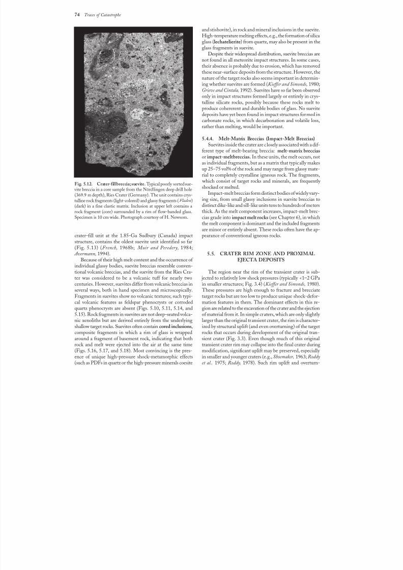
8/8/2019 Traces of Catastrophe - Book
http://slidepdf.com/reader/full/traces-of-catastrophe-book 85/130
74 Traces of Catastrophe
Fig.5.12. Crater-fill breccia; suevite.Typical poorly sorted sue- vite breccia in a core sample from the Nördlingen deep drill hole(369.9m depth), Ries Crater (Germany). The unit contains crys-talline rock fragments (light-colored) and glassy fragments (Fladen)(dark) in a fine clastic matrix. Inclusion at upper left contains arock fragment (core) surrounded by a rim of flow-banded glass.Specimen is 10 cm wide. Photograph courtesy of H. Newsom.
crater-fill unit at the 1.85-Ga Sudbury (Canada) impactstructure, contains the oldest suevite unit identified so far(Fig.5.13) (French, 1968b; Muir and Peredery, 1984;
Avermann, 1994).Because of their high melt content and the occurrence of
individual glassy bodies, suevite breccias resemble conven-tional volcanic breccias, and the suevite from the Ries Cra-ter was considered to be a volcanic tuff for nearly twocenturies. However, suevites differ from volcanic breccias inseveral ways, both in hand specimen and microscopically.Fragments in suevites show no volcanic textures; such typi-cal volcanic features as feldspar phenocrysts or corroded
quartz phenocrysts are absent (Figs. 5.10, 5.11, 5.14, and5.15). Rock fragments in suevites are not deep-seated volca-nic xenoliths but are derived entirely from the underlyingshallow target rocks. Suevites often contain cored inclusions,composite fragments in which a rim of glass is wrappedaround a fragment of basement rock, indicating that bothrock and melt were ejected into the air at the same time(Figs.5.16, 5.17, and 5.18). Most convincing is the pres-ence of unique high-pressure shock-metamorphic effects(such as PDFs in quartz or the high-pressure minerals coesite
and stishovite), in rock and mineral inclusions in the suevite.High-temperature melting effects, e.g., the formation of silicaglass (lechatelierite) from quartz, may also be present in theglass fragments in suevite.
Despite their widespread distribution, suevite breccias arenot found in all meteorite impact structures. In some cases,their absence is probably due to erosion, which has removedthese near-surface deposits from the structure. However, the
nature of the target rocks also seems important in determin-ing whether suevites are formed (Kieffer and Simonds, 1980;Grieve and Cintala, 1992). Suevites have so far been observedonly in impact structures formed largely or entirely in crys-talline silicate rocks, possibly because these rocks melt toproduce cohererent and durable bodies of glass. No suevitedeposits have yet been found in impact structures formed incarbonate rocks, in which decarbonation and volatile loss,rather than melting, would be important.
5.4.4. Melt-Matrix Breccias (Impact-Melt Breccias)Suevites inside the crater are closely associated with a dif-
ferent type of melt-bearing breccia: melt-matrix brecciasor impact-melt breccias. In these units, the melt occurs, notas individual fragments, but as a matrix that typically makesup 25–75 vol% of the rock and may range from glassy mate-rial to completely crystalline igneous rock. The fragments,
which consist of target rocks and minerals, are frequently shocked or melted.
Impact-melt breccias form distinct bodies of widely vary-ing size, from small glassy inclusions in suevite breccias todistinct dike-like and sill-like units tens to hundreds of metersthick. As the melt component increases, impact-melt brec-cias grade into impact melt rocks (see Chapter 6), in whichthe melt component is dominant and the included fragments
are minor or entirely absent. These rocks often have the ap-pearance of conventional igneous rocks.
5.5. CRATER RIM ZONE AND PROXIMALEJECTA DEPOSITS
The region near the rim of the transient crater is sub- jected to relatively low shock pressures (typically <1–2 GPain smaller structures; Fig. 3.4) (Kieffer and Simonds, 1980).
These pressures are high enough to fracture and brecciatetarget rocks but are too low to produce unique shock-defor-mation features in them. The dominant effects in this re-
gion are related to the excavation of the crater and the ejectionof material from it. In simple craters, which are only slightly larger than the original transient crater, the rim is character-ized by structural uplift (and even overturning) of the targetrocks that occurs during development of the original tran-sient crater (Fig. 3.3). Even though much of this originaltransient crater rim may collapse into the final crater duringmodification, significant uplift may be preserved, especially in smaller and younger craters (e.g., Shoemaker, 1963; Roddyet al., 1975; Roddy, 1978). Such rim uplift and overturn-
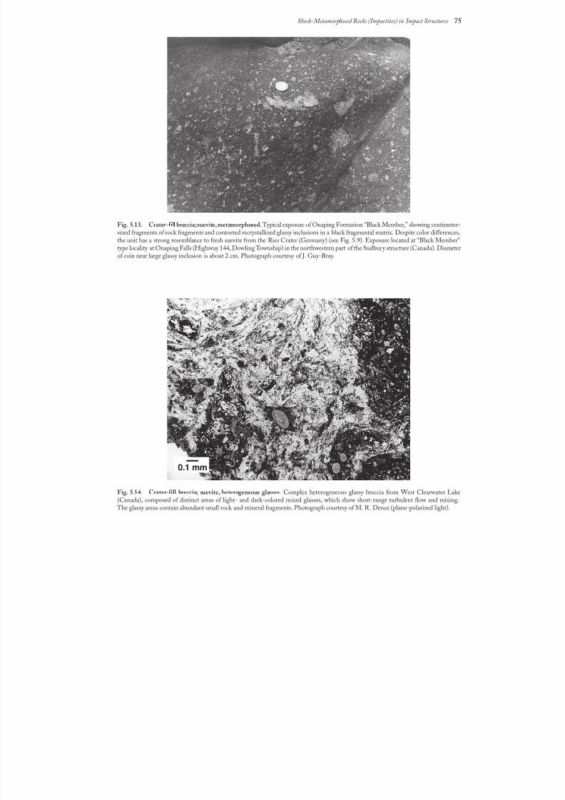
8/8/2019 Traces of Catastrophe - Book
http://slidepdf.com/reader/full/traces-of-catastrophe-book 86/130
Shock-Metamorphosed Rocks (Impactites) in Impact Structures 75
Fig.5.13. Crater-fill breccia; suevite, metamorphosed.Typical exposure of Onaping Formation “Black Member,” showing centimeter-sized fragments of rock fragments and contorted recrystallized glassy inclusions in a black fragmental matrix. Despite color differences,the unit has a strong resemblance to fresh suevite from the Ries Crater (Germany) (see Fig. 5.9). Exposure located at “Black Member”type locality at Onaping Falls (Highway 144, Dowling Township) in the northwestern part of the Sudbury structure (Canada). Diameterof coin near large glassy inclusion is about 2cm. Photograph courtesy of J. Guy-Bray.
Fig.5.14. Crater-fill breccia; suevite, heterogeneous glasses. Complex heterogeneous glassy breccia from West Clearwater Lake(Canada), composed of distinct areas of light- and dark-colored mixed glasses, which show short-range turbulent flow and mixing.
The glassy areas contain abundant small rock and mineral fragments. Photograph courtesy of M. R. Dence (plane-polarized light).
0.1 mm
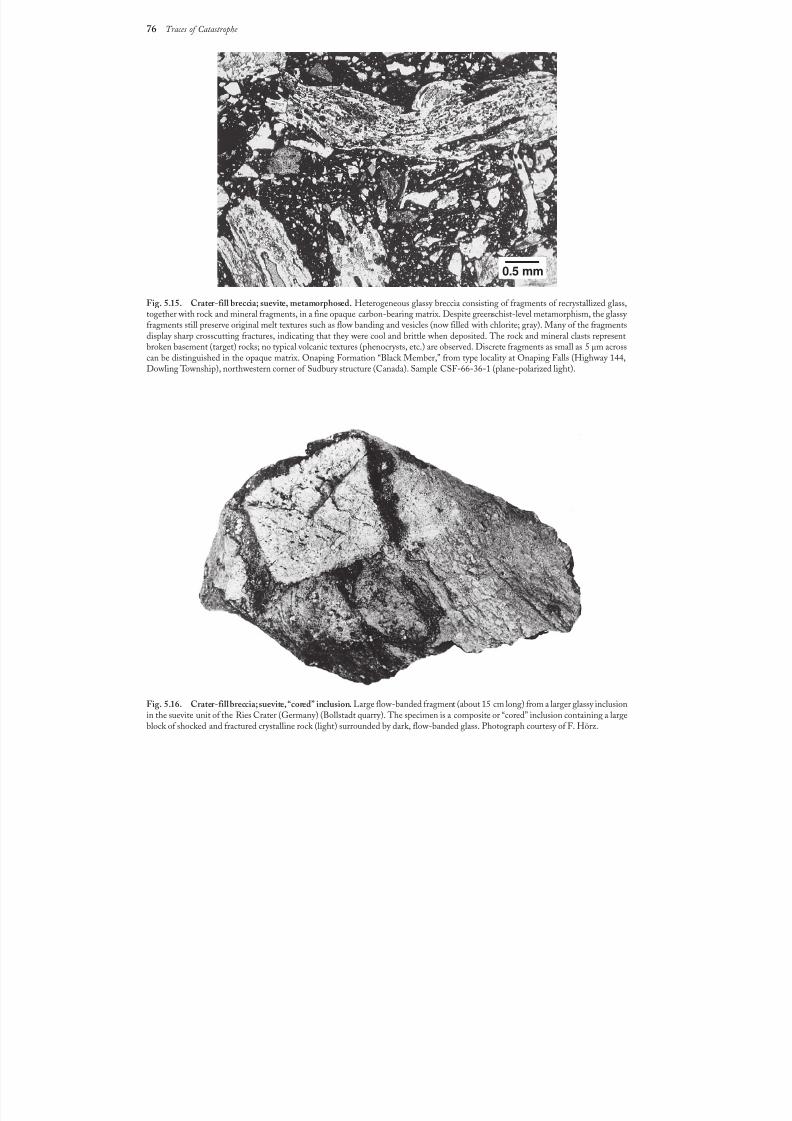
8/8/2019 Traces of Catastrophe - Book
http://slidepdf.com/reader/full/traces-of-catastrophe-book 87/130
76 Traces of Catastrophe
Fig.5.15. Crater-fill breccia; suevite, metamorphosed. Heterogeneous glassy breccia consisting of fragments of recrystallized glass,together with rock and mineral fragments, in a fine opaque carbon-bearing matrix. Despite greenschist-level metamorphism, the glassy fragments still preserve original melt textures such as flow banding and vesicles (now filled with chlorite; gray). Many of the fragmentsdisplay sharp crosscutting fractures, indicating that they were cool and brittle when deposited. The rock and mineral clasts representbroken basement (target) rocks; no typical volcanic textures (phenocrysts, etc.) are observed. Discrete fragments as small as 5 µm acrosscan be distinguished in the opaque matrix. Onaping Formation “Black Member,” from type locality at Onaping Falls (Highway 144,Dowling Township), northwestern corner of Sudbury structure (Canada). Sample CSF-66-36-1 (plane-polarized light).
Fig.5.16. Crater-fill breccia; suevite, “cored” inclusion. Large flow-banded fragment (about 15 cm long) from a larger glassy inclusionin the suevite unit of the Ries Crater (Germany) (Bollstadt quarry). The specimen is a composite or “cored” inclusion containing a largeblock of shocked and fractured crystalline rock (light) surrounded by dark, flow-banded glass. Photograph courtesy of F. Hörz.
0.5 mm
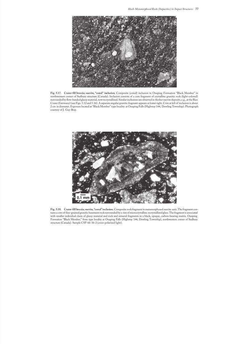
8/8/2019 Traces of Catastrophe - Book
http://slidepdf.com/reader/full/traces-of-catastrophe-book 88/130
Shock-Metamorphosed Rocks (Impactites) in Impact Structures 77
Fig.5.17. Crater-fill breccia; suevite, “cored” inclusion. Composite (cored) inclusion in Onaping Formation “Black Member” innorthwestern corner of Sudbury structure (Canada). Inclusion consists of a core fragment of crystalline granitic rock (light-colored)surrounded by flow-banded glassy material, now recrystallized. Similar inclusions are observed in fresher suevite deposits, e.g., at the RiesCrater (Germany) (see Figs. 5.12 and 5.16). A separate angular granitic fragment appears at lower right. Coin at left of inclusion is about2 cm in diameter. Exposure located at “Black Member” type locality at Onaping Falls (Highway 144, Dowling Township). Photographcourtesy of J. Guy-Bray.
Fig.5.18. Crater-fill breccia; suevite, “cored” inclusion. Composite rock fragment in metamorphosed suevite unit. The fragment con-tains a core of fine-grained granitic basement rock surrounded by a rim of microcrystalline recrystallized glass. The fragment is associated
with smaller individual clasts of glassy material and rock and mineral fragments in a black, opaque, carbon-bearing matrix. OnapingFormation “Black Member,” from type locality at Onaping Falls (Highway 144, Dowling Township), northwestern corner of Sudbury structure (Canada). Sample CSF-66-36-2 (cross-polarized light).
0.1 mm
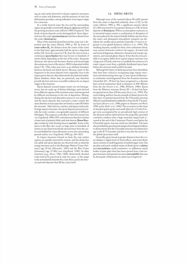
8/8/2019 Traces of Catastrophe - Book
http://slidepdf.com/reader/full/traces-of-catastrophe-book 89/130
78 Traces of Catastrophe
ing are only rarely observed in volcanic explosion structuressuch as maars and diatremes, and the presence of such rimdeformation provides a strong indication of an impactoriginfor a structure.
In a newly formed crater the rim and the surroundingregion are generally covered with allogenic ejecta ejected fromthe growing transient crater ( Melosh, 1989; Chapter 6). Twokinds of ejecta deposits can be distinguished: those depos-
ited near the crater (proximal ejecta ) and those distant fromthe crater (distal ejecta ).
Most of the material ejected beyond the crater rim is de-posited near the crater ( Melosh, 1989, p. 90). In terms of crater radius (R c, the distance from the center of the craterto the final rim), approximately half the ejecta is deposited
within 2 R c from the center (or 1 R c from the rim) to form acontinuous ejecta blanket that may be tens to hundreds of meters thick, depending on the size of the crater. At greaterdistances, the ejecta unit becomes thinner and increasingly discontinuous; most of the ejecta (>90%) is deposited withinabout 5 R c. (This value may serve as an arbitrary boundary between proximal and distal ejecta.) Because many of thefragments in the ejecta deposits were originally close to theimpact point, they are often distinctively shocked and melted.Ejecta blankets, where they are preserved, may thereforeprovide the best and most accessible evidence for an impactorigin of the structure.
Ejecta deposits around impact craters are not homoge-neous, but are made up of distinct lithologic units derivedfrom different regions of the transient crater and transportedby different mechanisms to the site of deposition. Mixingduring the ejection and deposition process is not complete,and the ejecta deposits that surround a crater contain thesame diversity of rock types that are found as crater fill within
the structure: lithic breccias, suevites, and impact melt rocks.In large impact structures, the ejecta deposits preserved out-side the crater contain a recognizable sequence of differentlithologies. The sequence at the Ries Crater (Germany) (seevon Engelhardt, 1990, 1997, and references therein) containsa lower unit of polymict lithic melt-free breccia (Bunte Brec-cia ) overlain by melt-bearing breccia (suevite). Some of theejecta at the Ries also occurs as large (tens to hundreds of meters in size) limestone blocks ejected intact from the cra-ter and skidded for many kilometers across the surroundingground surface (von Engelhardt, 1990, pp. 264–265).
In impact structures formed on land, the near-surfaceregions are quickly removed by erosion, and the distinctive
rim uplift and ejecta deposits are observed only at relatively young structures such as the Barringer Meteor Crater (Ari-zona) (age 50 ka) (Shoemaker, 1963) and the Ries Crater(Germany) (age 15 Ma) (von Engelhardt, 1990). At olderstructures (e.g., Dence, 1965, 1968), distinctively shockedrocks tend to be preserved in only two areas: in the targetrocks immediately beneath the crater floor, and in the brec-cia and melt deposits that fill the crater itself.
5.6. DISTAL EJECTA
Although most of the material (about 90 vol%) ejectedfrom the crater is deposited relatively close (<5 R c) to thecrater ( Melosh, 1989, p. 90), a significant amount (about10vol%) may travel to even greater distances (>5 R c) to formdeposits of distal ejecta . Where an atmosphere is present, asin terrestrial impact events, a combination of disruption of
the atmosphere by the impact fireball, ballistic ejection fromthe crater, and subsequent atmospheric transport can dis-tribute the smaller ejecta particles (typically >1 mm) to re-gional or even global distances ( Alvarez et al., 1995). Theresulting deposits, usually less than a few centimeters thick,may contain distinctive evidence for impact: shocked rock and mineral fragments, distinctive chemical and isotopic sig-natures, and unusual glassy objects. It has thus become pos-sible to recognize debris from a given impact structure overa large area of Earth, and even to establish the existence of amajor impact event from a globally distributed ejecta layerbefore the structure itself could be located.
Although few layers of distal ejecta have been identified,they have been critical to recognizing large impact struc-tures and determining their age. Coarse ejecta (millimeter-to centimeter-sized fragments) from the Acraman structure(Australia) (D = 90 km) has been recognized as a discretelayer several centimeters thick at distances of 300–400 kmfrom the site (Gostin et al., 1986; Williams, 1986). Ejectafrom the Manson structure (Iowa) (D = 36 km) has beenrecognized more than 250 km away ( Izett et al., 1993). Themost striking and best-known example of distal ejecta is thethin layer of material ejected from the Chicxulub structure(Mexico) and distributed worldwide to form the K/T bound-ary layer ( Alvarez et al., 1980; papers in Sharpton and Ward,
1990, and in Ryder et al., 1996). The occurrence in this layerof shocked quartz grains and small spherules of melted tar-get rock, accompanied by an anomalously high content of the element iridium (derived from the projectile), providedconclusive evidence that a large meteorite impact had oc-curred at the end of the Cretaceous Period, even before theChicxulub impact structure itself was identified. The layeralso provided key geochemical and geochronological evidenceto demonstrate that the Chicxulub structure was identical inage to the K/T boundary and that it was also the source forthe global ejecta layer itself.
Generally, ejecta found at greater distances from the cra-ter displays a higher level of shock effects, and much distal
ejecta consists of small fragments of melted target rock. Onepeculiar and much-studied variety of distal ejecta is tektitesand microtektites, small (centimeter- to millimeter-sized)bodies of pure glass that have been ejected from a few im-pact structures and spread over areas (strewnfields) that may be thousands of kilometers in extent (see Chapter 6).
8/8/2019 Traces of Catastrophe - Book
http://slidepdf.com/reader/full/traces-of-catastrophe-book 90/130
Impact Melts 79
79
Impact Melts
6.1. FORMATION CONDITIONS
One of the most unique features of the impact process isthe virtually instantaneous melting of significant amountsof target rock, followed by the rapid distribution of this im-pact melt throughout the resulting crater to produce a vari-ety of unusual crystalline and glassy igneous rocks. Allimpact-generated shock waves deposit some of their origi-nal energy as heat within the target rocks through whichthey pass. At relatively low shock pressures ( >40 GPa), theresulting postshock temperature rise is moderate ( >500°C),or below the melting points of most rock-forming minerals(Table 4.2). At higher pressure (~40–50 GPa), the higher
temperatures produce significant melting, and at pressures(>60 GPa) near the impact point, the shock waves depositsufficient thermal energy to completely melt a large volumeof target rock. The subsequent dynamic processes of craterformation spread this impact melt within and outside thecrater as small bodies of glass in breccias and as larger bodiesof crystalline igneous rock of varying size, shape, and ap-pearance (Dence, 1971; Grieve et al., 1977, 1991b; Grieve and Cintala, 1992; Schuraytz et al., 1994). In large (D >25km) impact structures, especially those produced in crys-talline igneous and metamorphic rocks, tens to hundreds of cubic kilometers of impact melt may be produced, and im-pact melt units can become a significant part of the geology
of the structure (Fig. 6.1). The formation of impact melts has no counterpart in other
geological processes, and many details of how impact meltsare formed, moved, and emplaced are still not clear. How-ever, some general features of the process and its geologicalconsequences have been outlined by combining theoreticalmodels with geological studies of impact structures (Dence,1971; Dence et al., 1977; Grieve, 1978; Grieve et al., 1977,1981, 1991b; Grieve and Cintala, 1992; Cintala and Grieve,1998). During the initial stages of an impact event at typi-cal cosmic encounter velocities, postshock temperatures
>2000°C are produced through a large volume of target rock close to the impact point (Fig. 3.2) (O’Keefe and Ahrens, 1975,1977; Ahrens and O’Keefe, 1977; Melosh, 1989, pp. 63–64and 122–123).
These postshock temperatures are far above the normalmelting points of the target rocks and their constituent min-erals. As a result, when the shock wave has passed and thepressure returns to normal, spontaneous and complete melt-ing occurs almost instantaneously throughout a large andapproximately spherical volume of target rock. The shock
waves that have melted the target rock also provide kineticenergy to accelerate the newly formed melt, which immedi-ately becomes part of the overall flow and movement of tar-
get rock that opens up the transient crater (Fig. 6.2) (Dence,1971; Grieve et al., 1981; Grieve, 1987).A special kind of melt formation and ejection may occur
during the earliest stages of contact in small regions near theinterface between the projectile and the target (Fig. 3.1). Inthis region, extremely high shock pressures are generated,producing correspondingly high temperatures (>5000°C) inthe shocked material. The resulting melted and vaporizedmaterial may then be ejected as high-velocity jets, at speedsthat may exceed the original impact velocity ( Melosh, 1989,pp. 51–53). Depending on the amount of atmospheric re-sistance encountered, the jets can carry material to signifi-cant distances, forming deposits of small spherules or larger
glassy bodies ( Melosh and Vickery, 1991). However, such ma-terial, which may be a mixture of vaporized projectile andtarget rock, is relatively minor in comparison to the large
volume of melt generated subsequently within the crater. This larger melt volume, initially located near the center
of the structure, is driven downward and outward towardthe floor of the developing transient crater at initial veloci-ties of a few kilometers per second (Fig. 6.2). When themelt reaches the transient crater floor, it turns and movesupward and outward along the floor (Grieve et al., 1977). Atthis point, the movement of the melt becomes slower and
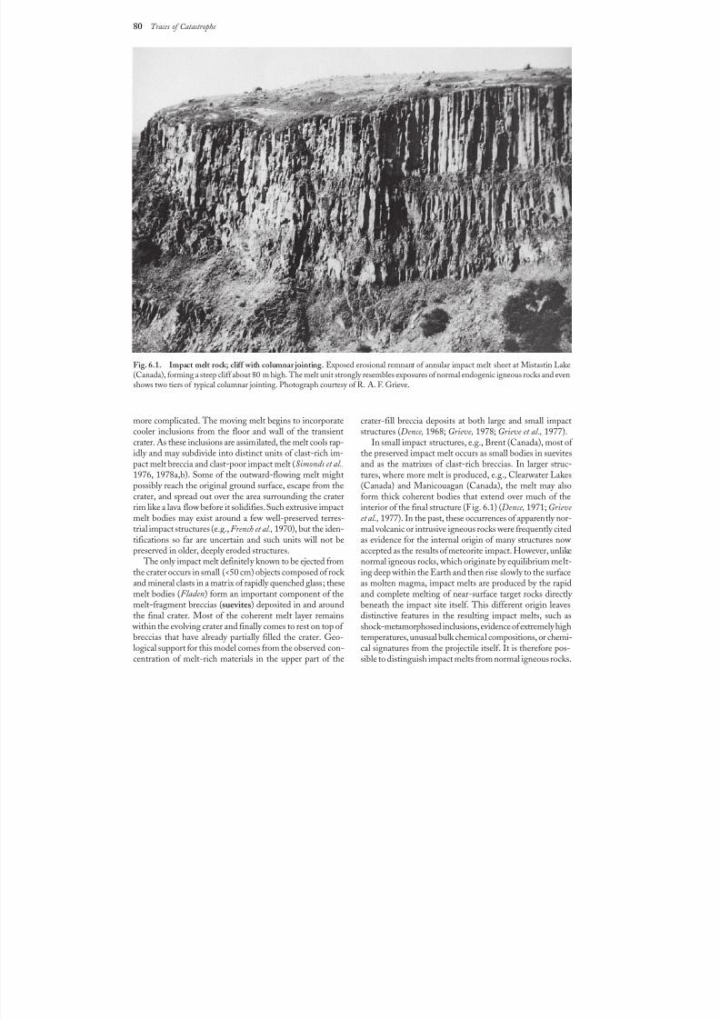
8/8/2019 Traces of Catastrophe - Book
http://slidepdf.com/reader/full/traces-of-catastrophe-book 91/130
80 Traces of Catastrophe
more complicated. The moving melt begins to incorporatecooler inclusions from the floor and wall of the transientcrater. As these inclusions are assimilated, the melt cools rap-idly and may subdivide into distinct units of clast-rich im-pact melt breccia and clast-poor impact melt (Simonds et al.,1976, 1978a,b). Some of the outward-flowing melt mightpossibly reach the original ground surface, escape from thecrater, and spread out over the area surrounding the craterrim like a lava flow before it solidifies. Such extrusive impactmelt bodies may exist around a few well-preserved terres-trial impact structures (e.g., French et al., 1970), but the iden-tifications so far are uncertain and such units will not be
preserved in older, deeply eroded structures. The only impact melt definitely known to be ejected from
the crater occurs in small (<50 cm) objects composed of rock and mineral clasts in a matrix of rapidly quenched glass; thesemelt bodies (Fladen) form an important component of themelt-fragment breccias (suevites) deposited in and aroundthe final crater. Most of the coherent melt layer remains
within the evolving crater and finally comes to rest on top of breccias that have already partially filled the crater. Geo-logical support for this model comes from the observed con-centration of melt-rich materials in the upper part of the
crater-fill breccia deposits at both large and small impactstructures (Dence, 1968; Grieve, 1978; Grieve et al., 1977).
In small impact structures, e.g., Brent (Canada), most of the preserved impact melt occurs as small bodies in suevitesand as the matrixes of clast-rich breccias. In larger struc-tures, where more melt is produced, e.g., Clearwater Lakes(Canada) and Manicouagan (Canada), the melt may alsoform thick coherent bodies that extend over much of theinterior of the final structure (Fig. 6.1) (Dence, 1971; Grieve et al., 1977). In the past, these occurrences of apparently nor-mal volcanic or intrusive igneous rocks were frequently citedas evidence for the internal origin of many structures now
accepted as the results of meteorite impact. However, unlikenormal igneous rocks, which originate by equilibrium melt-ing deep within the Earth and then rise slowly to the surfaceas molten magma, impact melts are produced by the rapidand complete melting of near-surface target rocks directly beneath the impact site itself. This different origin leavesdistinctive features in the resulting impact melts, such asshock-metamorphosed inclusions, evidence of extremely hightemperatures, unusual bulk chemical compositions, or chemi-cal signatures from the projectile itself. It is therefore pos-sible to distinguish impact melts from normal igneous rocks.
Fig. 6.1. Impact melt rock; cliff with columnar jointing. Exposed erosional remnant of annular impact melt sheet at Mistastin Lake(Canada), forming a steep cliff about 80 m high. The melt unit strongly resembles exposures of normal endogenic igneous rocks and evenshows two tiers of typical columnar jointing. Photograph courtesy of R. A. F. Grieve.
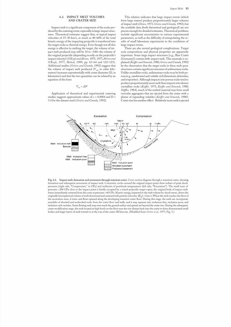
8/8/2019 Traces of Catastrophe - Book
http://slidepdf.com/reader/full/traces-of-catastrophe-book 92/130
Impact Melts 81
, , , , , , ,
, , , , , , ,
, , , , , , ,
, , , , , , ,
, , , , , , ,
,
,
,
,
,
,
,
,
,
,
,
,
,
,
,
,
,
,
,
,
,
,
,
,
y
y
y
y
y
y
y
y
y
y
y
y
y
y
y
y
y
y
y
y
y
y
y
y
, , , ,
, , , ,
, , , ,
, , , ,
, ,
, y
,
,
, ,
,
,
y
y
, ,
,
,
, ,
, ,
,
Fig. 6.2. Impact melt; formation and movement through transient crater. Cross-section diagram through a transient crater, showingformation and subsequent movement of impact melt. Concentric circles around the original impact point show isobars of peak shock pressures (right side, “Compression,” in GPa) and isotherms of postshock temperatures (left side, “Excavation”). The small zone of pressures >200 GPa close to the impact point is briefly occupied by a mixed projectile-target vapor; the original body of impact meltforms immediately outward from this zone at pressures >60 GPa. Kinetic energy, imparted to the melt volume by shock waves, drives theoriginally hemispherical volume of melt downward and outward with particle velocities (Up) >1 km/s. When the melt reaches the floor of the excavation zone, it turns and flows upward along the developing transient crater floor. During this stage, the melt can incorporate
xenoliths of shocked and unshocked rocks from the crater floor and walls, and it may separate into inclusion-free, inclusion-poor, andinclusion-rich varieties. Some flowing melt may even reach the ground surface and spread out beyond the crater rim. During the subsequentcrater modification stage, the melt located at high levels on the floor near the rim slumps back into the crater to form disseminated smallbodies and larger layers of melt toward or at the top of the crater-fill breccias. (Modified from Grieve et al., 1977, Fig.5.)
6.2. IMPACT MELT VOLUMES AND CRATER SIZE
Impact melt is a significant component of the rocks pro-duced by the cratering event, especially in large impact struc-tures. Theoretical estimates suggest that, at typical impact
velocities of 15–30 km/s, as much as 40–60% of the totalkinetic energy of the impacting projectile is transferred into
the target rocks as thermal energy. Even though not all thisenergy is effective in melting the target, the volume of im-pact melt produced may still be 10 to >100× the volume of the original projectile (depending mostly on the projectile’simpact velocity) (O’Keefe and Ahrens, 1975, 1977; Ahrens and O’Keefe, 1977; Melosh, 1989, pp. 63–64 and 122–123).Additional studies (Grieve and Cintala, 1992) suggest thatthe volume of impact melt produced (V m, in cubic kilo-meters) increases expontentially with crater diameter (D, inkilometers) and that the two quantities can be related by anequation of the form
V m
= cDd
Application of theoretical and experimental crateringstudies suggests approximate values of c = 0.0004 and D =3.4 for the dataset used (Grieve and Cintala, 1992).
This relation indicates that large impact events (whichform large craters) produce proportionately larger volumesof impact melt (Dence, 1971; Grieve and Cintala, 1992), butthe available data (both theoretical and geological) are notprecise enough for detailed estimates. Theoretical problemsinclude significant uncertainties in various experimentalparameters, as well as the difficulty of extrapolating the re-sults of small laboratory experiments to the conditions of
large impact events. There are also several geological complications. Target
rock compositions and physical properties are apparently important. Some large impact structures [e.g., Ries Crater(Germany)] contain little impact melt. This anomaly is ex-plained (Kieffer and Simonds, 1980; Grieve and Cintala, 1992)by the observation that the target rocks in these melt-poorstructures contain significant amounts of sedimentary rocks.Unlike crystalline rocks, sedimentary rocks may be both po-rous (e.g., sandstones) and volatile-rich (limestone, dolomites,and evaporites). Although impacts into porous rocks tend toproduce proportionately more melt than impacts into densercrystalline rocks (Kieffer, 1971; Kieffer and Simonds, 1980;Stöffler, 1984), much of the melted material may form small
vesicular aggregates that are ejected from the crater with aplume of expanding volatiles (Kieffer and Simonds, 1980).Crater size has another effect: Relatively more melt is ejected
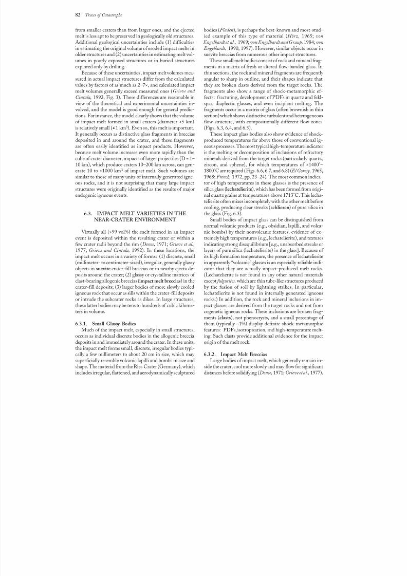
8/8/2019 Traces of Catastrophe - Book
http://slidepdf.com/reader/full/traces-of-catastrophe-book 93/130
82 Traces of Catastrophe
from smaller craters than from larger ones, and the ejectedmelt is less apt to be preserved in geologically old structures.Additional geological uncertainties include (1) difficultiesin estimating the original volume of eroded impact melts inolder structures and (2) uncertainties in estimating melt vol-umes in poorly exposed structures or in buried structuresexplored only by drilling.
Because of these uncertainties, impact melt volumes mea-
sured in actual impact structures differ from the calculated values by factors of as much as 2–7×, and calculated impactmelt volumes generally exceed measured ones (Grieve and Cintala, 1992, Fig. 3). These differences are reasonable in
view of the theoretical and experimental uncertainties in- volved, and the model is good enough for general predic-tions. For instance, the model clearly shows that the volumeof impact melt formed in small craters (diameter <5 km)is relatively small ( >1 km3). Even so, this melt is important.It generally occurs as distinctive glass fragments in brecciasdeposited in and around the crater, and these fragmentsare often easily identified as impact products. However,because melt volume increases even more rapidly than thecube of crater diameter, impacts of larger projectiles (D = 1–10 km), which produce craters 10–200 km across, can gen-erate 10 to >1000 km3 of impact melt. Such volumes aresimilar to those of many units of internally generated igne-ous rocks, and it is not surprising that many large impactstructures were originally identified as the results of majorendogenic igneous events.
6.3. IMPACT MELT VARIETIES IN THENEAR-CRATER ENVIRONMENT
Virtually all (>99 vol%) the melt formed in an impactevent is deposited within the resulting crater or within afew crater radii beyond the rim (Dence, 1971; Grieve et al.,1977; Grieve and Cintala, 1992). In these locations, theimpact melt occurs in a variety of forms: (1) discrete, small(millimeter- to centimeter-sized), irregular, generally glassy objects in suevite crater-fill breccias or in nearby ejecta de-posits around the crater; (2) glassy or crystalline matrices of clast-bearing allogenic breccias (impact melt breccias) in thecrater-fill deposits; (3) larger bodies of more slowly cooledigneous rock that occur as sills within the crater-fill depositsor intrude the subcrater rocks as dikes. In large structures,these latter bodies may be tens to hundreds of cubic kilome-
ters in volume.
6.3.1. Small Glassy BodiesMuch of the impact melt, especially in small structures,
occurs as individual discrete bodies in the allogenic brecciadeposits in and immediately around the crater. In these units,the impact melt forms small, discrete, irregular bodies typi-cally a few millimeters to about 20 cm in size, which may superficially resemble volcanic lapilli and bombs in size andshape. The material from the Ries Crater (Germany), whichincludes irregular, flattened, and aerodynamically sculptured
bodies (Fladen), is perhaps the best-known and most-stud-ied example of this type of material (Hörz, 1965; von
Engelhardt et al., 1969; von Engelhardt and Graup, 1984; von Engelhardt, 1990, 1997). However, similar objects occur insuevite breccias from numerous other impact structures.
These small melt bodies consist of rock and mineral frag-ments in a matrix of fresh or altered flow-banded glass. Inthin sections, the rock and mineral fragments are frequently
angular to sharp in outline, and their shapes indicate thatthey are broken clasts derived from the target rocks. Thefragments also show a range of shock-metamorphic ef-fects: fracturing, development of PDFs in quartz and feld-spar, diaplectic glasses, and even incipient melting. Thefragments occur in a matrix of glass (often brownish in thinsection) which shows distinctive turbulent and heterogeneousflow structure, with compositionally different flow zones(Figs. 6.3, 6.4, and 6.5).
These impact glass bodies also show evidence of shock-produced temperatures far above those of conventional ig-neous processes. The most typical high-temperature indicatoris the melting or decomposition of inclusions of refractory minerals derived from the target rocks (particularly quartz,zircon, and sphene), for which temperatures of >1400°–1800°C are required (Figs. 6.6, 6.7, and 6.8) ( El Goresy, 1965,1968; French, 1972, pp. 23–24). The most common indica-tor of high temperatures in these glasses is the presence of silica glass (lechatelierite), which has been formed from origi-nal quartz grains at temperatures above 1713°C. This lecha-telierite often mixes incompletely with the other melt beforecooling, producing clear streaks (schlieren) of pure silica inthe glass (Fig. 6.3).
Small bodies of impact glass can be distinguished fromnormal volcanic products (e.g., obsidian, lapilli, and volca-
nic bombs) by their nonvolcanic features, evidence of ex-tremely high temperatures (e.g., lechatelierite), and texturesindicating strong disequilibrium [e.g., unabsorbed streaks orlayers of pure silica (lechatelierite) in the glass]. Because of its high formation temperature, the presence of lechatelieritein apparently “volcanic” glasses is an especially reliable indi-cator that they are actually impact-produced melt rocks.(Lechatelierite is not found in any other natural materialsexcept fulgurites, which are thin tube-like structures producedby the fusion of soil by lightning strikes. In particular,lechatelierite is not found in internally generated igneousrocks.) In addition, the rock and mineral inclusions in im-pact glasses are derived from the target rocks and not from
cogenetic igneous rocks. These inclusions are broken frag-ments (clasts), not phenocrysts, and a small percentage of them (typically ~1%) display definite shock-metamorphicfeatures: PDFs, isotropization, and high-temperature melt-ing. Such clasts provide additional evidence for the impactorigin of the melt rock.
6.3.2. Impact Melt BrecciasLarge bodies of impact melt, which generally remain in-
side the crater, cool more slowly and may flow for significantdistances before solidifying (Dence, 1971; Grieve et al., 1977).
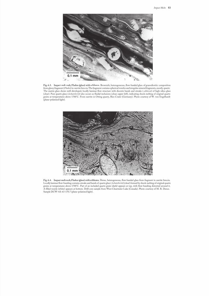
8/8/2019 Traces of Catastrophe - Book
http://slidepdf.com/reader/full/traces-of-catastrophe-book 94/130
Impact Melts 83
Fig. 6.3. Impact melt rock; Fladen (glass) with schlieren. Brownish, heterogeneous, flow-banded glass of granodioritic compositionfrom glassy fragment (Fladen) in suevite breccia. The fragment contains spherical vesicles and irregular mineral fragments, mostly quartz.
The matrix glass shows well-developed, locally laminar flow structure with discrete bands and streaks (schlieren) of high-silica glass(clear). Pure quartz glass (lechatelierite ) also occurs as fluidal inclusions (clear; upper left), indicating shock melting of original quartz grains at temperatures above 1700°C. From suevite in Otting quarry, Ries Crater (Germany). Photo courtesy of W. von Engelhardt(plane-polarized light).
Fig. 6.4. Impact melt rock; Fladen (glass) with schlieren. Dense, heterogeneous, flow-banded glass from fragment in suevite breccia.Locally laminar flow-banding contains streaks and bands of quartz glass (lechatelierite ) (clear) formed by shock melting of original quartz grains at temperatures above 1700°C. Part of an included quartz grain (dark) appears at top, with flow-banding distorted around it.A filled vesicle (white) appears at bottom. Drill core sample from West Clearwater Lake (Canada). Photo courtesy of M. R. Dence.Sample DCW-4A-63-170.7 (plane-polarized light).
0.1 mm
0.1 mm

8/8/2019 Traces of Catastrophe - Book
http://slidepdf.com/reader/full/traces-of-catastrophe-book 95/130
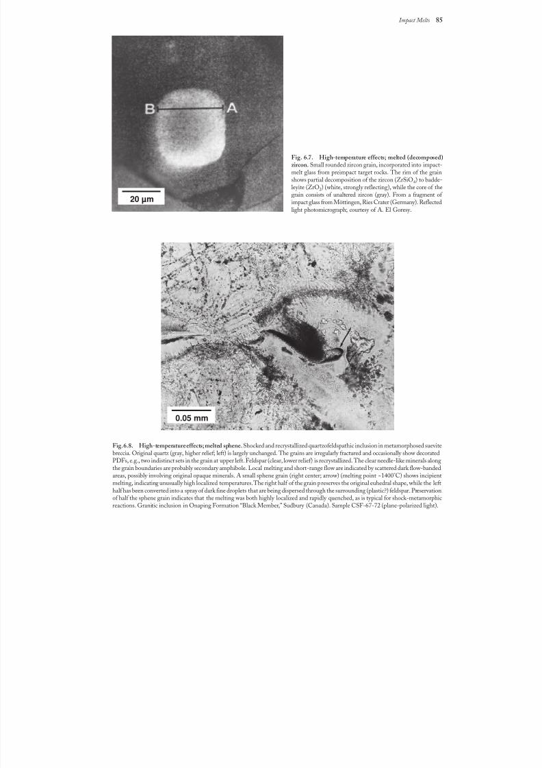
8/8/2019 Traces of Catastrophe - Book
http://slidepdf.com/reader/full/traces-of-catastrophe-book 96/130
Impact Melts 85
Fig. 6.7. High-temperature effects; melted (decomposed)zircon. Small rounded zircon grain, incorporated into impact-melt glass from preimpact target rocks. The rim of the grainshows partial decomposition of the zircon (ZrSiO4) to badde-leyite (ZrO2) (white, strongly reflecting), while the core of thegrain consists of unaltered zircon (gray). From a fragment of impact glass from Möttingen, Ries Crater (Germany). Reflected
light photomicrograph; courtesy of A. El Goresy.
Fig. 6.8. High-temperature effects; melted sphene.Shocked and recrystallized quartzofeldspathic inclusion in metamorphosed suevitebreccia. Original quartz (gray, higher relief; left) is largely unchanged. The grains are irregularly fractured and occasionally show decoratedPDFs, e.g., two indistinct sets in the grain at upper left. Feldspar (clear, lower relief) is recrystallized. The clear needle-like minerals alongthe grain boundaries are probably secondary amphibole. Local melting and short-range flow are indicated by scattered dark flow-bandedareas, possibly involving original opaque minerals. A small sphene grain (right center; arrow) (melting point ~1400°C) shows incipientmelting, indicating unusually high localized temperatures. The right half of the grain preserves the original euhedral shape, while the lefthalf has been converted into a spray of dark fine droplets that are being dispersed through the surrounding (plastic?) feldspar. Preservationof half the sphene grain indicates that the melting was both highly localized and rapidly quenched, as is typical for shock-metamorphicreactions. Granitic inclusion in Onaping Formation “Black Member,” Sudbury (Canada). Sample CSF-67-72 (plane-polarized light).
0.05 mm
20 µm
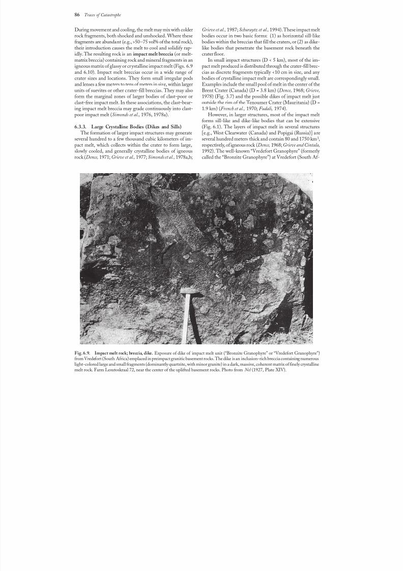
8/8/2019 Traces of Catastrophe - Book
http://slidepdf.com/reader/full/traces-of-catastrophe-book 97/130
86 Traces of Catastrophe
During movement and cooling, the melt may mix with colderrock fragments, both shocked and unshocked. Where thesefragments are abundant (e.g., >50–75 vol% of the total rock),their introduction causes the melt to cool and solidify rap-idly. The resulting rock is an impact melt breccia (or melt-matrix breccia) containing rock and mineral fragments in anigneous matrix of glassy or crystalline impact melt (Figs.6.9and 6.10). Impact melt breccias occur in a wide range of
crater sizes and locations. They form small irregular podsand lenses a few meters to tens of meters in size, within largerunits of suevites or other crater-fill breccias. They may alsoform the marginal zones of larger bodies of clast-poor orclast-free impact melt. In these associations, the clast-bear-ing impact melt breccia may grade continuously into clast-poor impact melt (Simonds et al., 1976, 1978a).
6.3.3. Large Crystalline Bodies (Dikes and Sills) The formation of larger impact structures may generate
several hundred to a few thousand cubic kilometers of im-pact melt, which collects within the crater to form large,slowly cooled, and generally crystalline bodies of igneousrock (Dence, 1971; Grieve et al., 1977; Simonds et al., 1978a,b;
Grieve et al., 1987; Schuraytz et al., 1994). These impact meltbodies occur in two basic forms: (1) as horizontal sill-likebodies within the breccias that fill the craters, or (2) as dike-like bodies that penetrate the basement rock beneath thecrater floor.
In small impact structures (D < 5 km), most of the im-pact melt produced is distributed through the crater-fill brec-cias as discrete fragments typically <10 cm in size, and any
bodies of crystalline impact melt are correspondingly small.Examples include the small pool of melt in the center of theBrent Crater (Canada) (D = 3.8 km) (Dence, 1968; Grieve,1978) (Fig. 3.7) and the possible dikes of impact melt justoutside the rim of the Tenoumer Crater (Mauritania) (D =1.9 km) (French et al., 1970; Fudali, 1974).
However, in larger structures, most of the impact meltforms sill-like and dike-like bodies that can be extensive(Fig.6.1). The layers of impact melt in several structures[e.g., West Clearwater (Canada) and Popigai (Russia)] areseveral hundred meters thick and contain 80 and 1750 km3,respectively, of igneous rock (Dence, 1968; Grieve and Cintala,1992). The well-known “Vredefort Granophyre” (formerly called the “Bronzite Granophyre”) at Vredefort (South Af-
Fig. 6.9. Impact melt rock; breccia, dike. Exposure of dike of impact melt unit (“Bronzite Granophyre” or “Vredefort Granophyre”)from Vredefort (South Africa) emplaced in preimpact granitic basement rocks. The dike is an inclusion-rich breccia containing numerouslight-colored large and small fragments (dominantly quartzite, with minor granite) in a dark, massive, coherent matrix of finely crystallinemelt rock. Farm Lesutoskraal 72, near the center of the uplifted basement rocks. Photo from Nel (1927, Plate XIV).
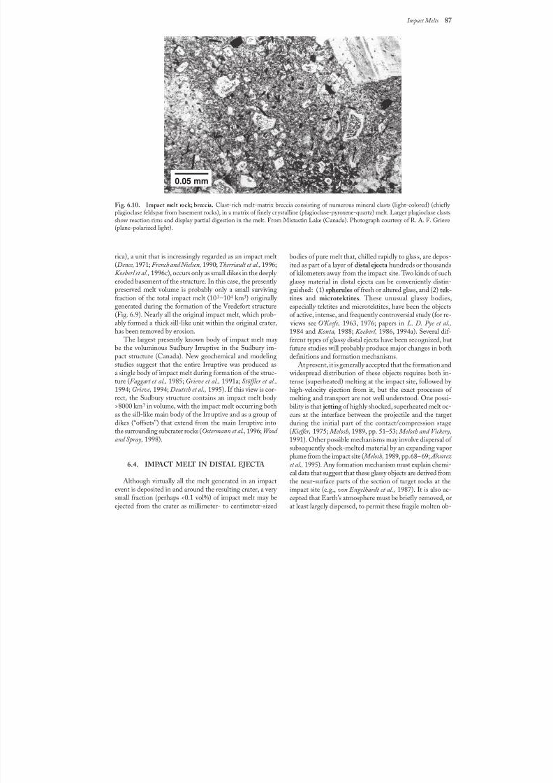
8/8/2019 Traces of Catastrophe - Book
http://slidepdf.com/reader/full/traces-of-catastrophe-book 98/130
Impact Melts 87
rica), a unit that is increasingly regarded as an impact melt(Dence, 1971; French and Nielsen, 1990; Therriault et al., 1996;Koeberl et al., 1996c), occurs only as small dikes in the deeply eroded basement of the structure. In this case, the presently preserved melt volume is probably only a small survivingfraction of the total impact melt (103–104 km3) originally generated during the formation of the Vredefort structure
(Fig. 6.9). Nearly all the original impact melt, which prob-ably formed a thick sill-like unit within the original crater,has been removed by erosion.
The largest presently known body of impact melt may be the voluminous Sudbury Irruptive in the Sudbury im-pact structure (Canada). New geochemical and modelingstudies suggest that the entire Irruptive was produced asa single body of impact melt during formation of the struc-ture (Faggart et al., 1985; Grieve et al., 1991a; Stöffler et al.,1994; Grieve, 1994; Deutsch et al., 1995). If this view is cor-rect, the Sudbury structure contains an impact melt body >8000 km3 in volume, with the impact melt occurring bothas the sill-like main body of the Irruptive and as a group of
dikes (“offsets”) that extend from the main Irruptive intothe surrounding subcrater rocks (Ostermann et al., 1996; Wood and Spray, 1998).
6.4. IMPACT MELT IN DISTAL EJECTA
Although virtually all the melt generated in an impactevent is deposited in and around the resulting crater, a very small fraction (perhaps <0.1 vol%) of impact melt may beejected from the crater as millimeter- to centimeter-sized
Fig. 6.10. Impact melt rock; breccia. Clast-rich melt-matrix breccia consisting of numerous mineral clasts (light-colored) (chiefly
plagioclase feldspar from basement rocks), in a matrix of finely crystalline (plagioclase-pyroxene-quartz) melt. Larger plagioclase clastsshow reaction rims and display partial digestion in the melt. From Mistastin Lake (Canada). Photograph courtesy of R. A. F. Grieve(plane-polarized light).
bodies of pure melt that, chilled rapidly to glass, are depos-ited as part of a layer of distal ejecta hundreds or thousandsof kilometers away from the impact site. Two kinds of suchglassy material in distal ejecta can be conveniently distin-guished: (1) spherules of fresh or altered glass, and (2) tek-tites and microtektites. These unusual glassy bodies,especially tektites and microtektites, have been the objects
of active, intense, and frequently controversial study (for re- views see O’Keefe, 1963, 1976; papers in L. D. Pye et al.,1984 and Konta, 1988; Koeberl, 1986, 1994a). Several dif-ferent types of glassy distal ejecta have been recognized, butfuture studies will probably produce major changes in bothdefinitions and formation mechanisms.
At present, it is generally accepted that the formation and widespread distribution of these objects requires both in-tense (superheated) melting at the impact site, followed by high-velocity ejection from it, but the exact processes of melting and transport are not well understood. One possi-bility is that jetting of highly shocked, superheated melt oc-curs at the interface between the projectile and the target
during the initial part of the contact/compression stage(Kieffer, 1975; Melosh, 1989, pp. 51–53; Melosh and Vickery,1991). Other possible mechanisms may involve dispersal of subsequently shock-melted material by an expanding vaporplume from the impact site ( Melosh, 1989, pp. 68–69; Alvarezet al., 1995). Any formation mechanism must explain chemi-cal data that suggest that these glassy objects are derived fromthe near-surface parts of the section of target rocks at theimpact site (e.g., von Engelhardt et al., 1987). It is also ac-cepted that Earth’s atmosphere must be briefly removed, orat least largely dispersed, to permit these fragile molten ob-
0.05 mm
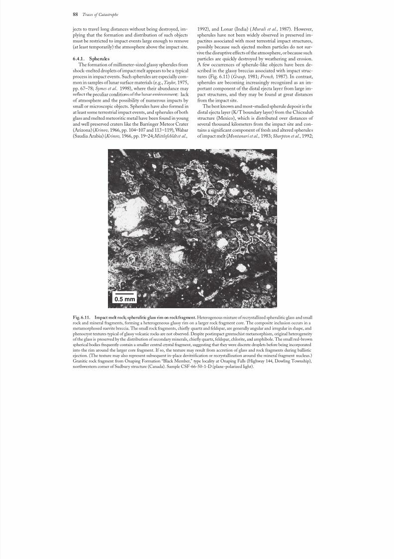
8/8/2019 Traces of Catastrophe - Book
http://slidepdf.com/reader/full/traces-of-catastrophe-book 99/130
88 Traces of Catastrophe
jects to travel long distances without being destroyed, im-plying that the formation and distribution of such objectsmust be restricted to impact events large enough to remove(at least temporarily) the atmosphere above the impact site.
6.4.1. Spherules The formation of millimeter-sized glassy spherules from
shock-melted droplets of impact melt appears to be a typical
process in impact events. Such spherules are especially com-mon in samples of lunar surface materials (e.g., Taylor, 1975,pp. 67–78; Symes et al., 1998), where their abundance may reflect the peculiar conditions of the lunar environment: lack of atmosphere and the possibility of numerous impacts by small or microscopic objects. Spherules have also formed inat least some terrestrial impact events, and spherules of bothglass and melted meteoritic metal have been found in youngand well preserved craters like the Barringer Meteor Crater(Arizona) (Krinov, 1966, pp. 104–107 and 113–119), Wabar(Saudia Arabia) (Krinov, 1966, pp. 19–24; Mittlefehldt etal.,
1992), and Lonar (India) ( Murali et al., 1987). However,spherules have not been widely observed in preserved im-pactites associated with most terrestrial impact structures,possibly because such ejected molten particles do not sur-
vive the disruptive effects of the atmosphere, or because suchparticles are quickly destroyed by weathering and erosion.A few occurrences of spherule-like objects have been de-scribed in the glassy breccias associated with impact struc-
tures (Fig.6.11) (Graup, 1981; French, 1987). In contrast,spherules are becoming increasingly recognized as an im-portant component of the distal ejecta layer from large im-pact structures, and they may be found at great distancesfrom the impact site.
The best known and most-studied spherule deposit is thedistal ejecta layer (K/T boundary layer) from the Chicxulubstructure (Mexico), which is distributed over distances of several thousand kilometers from the impact site and con-tains a significant component of fresh and altered spherulesof impact melt ( Montanari et al., 1983; Sharpton et al., 1992;
Fig. 6.11. Impact melt rock; spherulitic glass rim on rock fragment. Heterogenous mixture of recrystallized spherulitic glass and smallrock and mineral fragments, forming a heterogeneous glassy rim on a larger rock fragment core. The composite inclusion occurs in ametamorphosed suevite breccia. The small rock fragments, chiefly quartz and feldspar, are generally angular and irregular in shape, andphenocryst textures typical of glassy volcanic rocks are not observed. Despite postimpact greenschist metamorphism, original heterogeneity of the glass is preserved by the distribution of secondary minerals, chiefly quartz, feldspar, chlorite, and amphibole. The small red-brownspherical bodies frequently contain a smaller central crystal fragment, suggesting that they were discrete droplets before being incorporatedinto the rim around the larger core fragment. If so, the texture may result from accretion of glass and rock fragments during ballisticejection. (The texture may also represent subsequent in-place devitrification or recrystallization around the mineral fragment nucleus.)Granitic rock fragment from Onaping Formation “Black Member,” type locality at Onaping Falls (Highway 144, Dowling Township),northwestern corner of Sudbury structure (Canada). Sample CSF-66-50-1-D (plane-polarized light).
0.5 mm
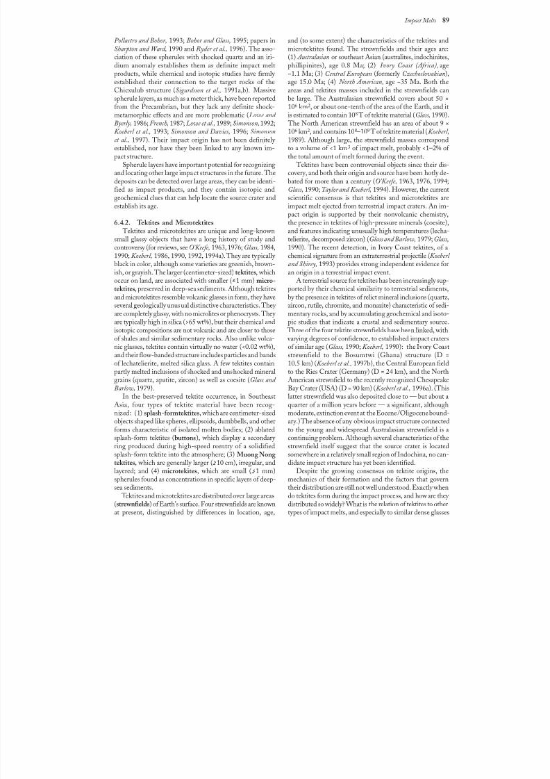
8/8/2019 Traces of Catastrophe - Book
http://slidepdf.com/reader/full/traces-of-catastrophe-book 100/130
Impact Melts 89
Pollastro and Bohor, 1993; Bohor and Glass, 1995; papers inSharpton and Ward, 1990 and Ryder et al., 1996). The asso-ciation of these spherules with shocked quartz and an iri-dium anomaly establishes them as definite impact meltproducts, while chemical and isotopic studies have firmly established their connection to the target rocks of theChicxulub structure (Sigurdsson et al., 1991a,b). Massivespherule layers, as much as a meter thick, have been reported
from the Precambrian, but they lack any definite shock-metamorphic effects and are more problematic (Lowe and Byerly, 1986; French, 1987; Lowe et al., 1989; Simonson,1992;Koeberl et al., 1993; Simonson and Davies, 1996; Simonsonet al., 1997). Their impact origin has not been definitely established, nor have they been linked to any known im-pact structure.
Spherule layers have important potential for recognizingand locating other large impact structures in the future. Thedeposits can be detected over large areas, they can be identi-fied as impact products, and they contain isotopic andgeochemical clues that can help locate the source crater andestablish its age.
6.4.2. Tektites and Microtektites Tektites and microtektites are unique and long-known
small glassy objects that have a long history of study andcontroversy (for reviews, see O’Keefe, 1963, 1976; Glass, 1984,1990; Koeberl, 1986, 1990, 1992, 1994a). They are typically black in color, although some varieties are greenish, brown-ish, or grayish. The larger (centimeter-sized) tektites, whichoccur on land, are associated with smaller ( >1 mm) micro-tektites, preserved in deep-sea sediments. Although tektitesand microtektites resemble volcanic glasses in form, they haveseveral geologically unusual distinctive characteristics. They
are completely glassy, with no microlites or phenocrysts. They are typically high in silica (>65 wt%), but their chemical andisotopic compositions are not volcanic and are closer to thoseof shales and similar sedimentary rocks. Also unlike volca-nic glasses, tektites contain virtually no water (<0.02 wt%),and their flow-banded structure includes particles and bandsof lechatelierite, melted silica glass. A few tektites containpartly melted inclusions of shocked and unshocked mineralgrains (quartz, apatite, zircon) as well as coesite (Glass and Barlow, 1979).
In the best-preserved tektite occurrence, in SoutheastAsia, four types of tektite material have been recog-nized: (1)splash-form tektites, which are centimeter-sized
objects shaped like spheres, ellipsoids, dumbbells, and otherforms characteristic of isolated molten bodies; (2) ablatedsplash-form tektites (buttons), which display a secondary ring produced during high-speed reentry of a solidifiedsplash-form tektite into the atmosphere; (3) Muong Nong tektites, which are generally larger (>10 cm), irregular, andlayered; and (4) microtekites, which are small ( >1 mm)spherules found as concentrations in specific layers of deep-sea sediments.
Tektites and microtektites are distributed over large areas(strewnfields) of Earth’s surface. Four strewnfields are knownat present, distinguished by differences in location, age,
and (to some extent) the characteristics of the tektites andmicrotektites found. The strewnfields and their ages are:(1) Australasian or southeast Asian (australites, indochinites,phillipinites), age 0.8 Ma; (2) Ivory Coast (Africa), age~1.1Ma; (3) Central European (formerly Czechoslovakian),age 15.0 Ma; (4) North American, age ~35 Ma. Both theareas and tektites masses included in the strewnfields canbe large. The Australasian strewnfield covers about 50 ×
106km2, or about one-tenth of the area of the Earth, and itis estimated to contain 108 T of tektite material (Glass, 1990).
The North American strewnfield has an area of about 9 ×10⁶ km2, and contains 108–109 T of tektite material (Koeberl,1989). Although large, the strewnfield masses correspondto a volume of <1 km3 of impact melt, probably <1–2% of the total amount of melt formed during the event.
Tektites have been controversial objects since their dis-covery, and both their origin and source have been hotly de-bated for more than a century (O’Keefe, 1963, 1976, 1994;Glass, 1990; Taylor and Koeberl, 1994). However, the currentscientific consensus is that tektites and microtektites areimpact melt ejected from terrestrial impact craters. An im-pact origin is supported by their nonvolcanic chemistry,the presence in tektites of high-pressure minerals (coesite),and features indicating unusually high temperatures (lecha-telierite, decomposed zircon) (Glass and Barlow, 1979; Glass,1990). The recent detection, in Ivory Coast tektites, of achemical signature from an extraterrestrial projectile (Koeberl and Shirey, 1993) provides strong independent evidence foran origin in a terrestrial impact event.
A terrestrial source for tektites has been increasingly sup-ported by their chemical similarity to terrestrial sediments,by the presence in tektites of relict mineral inclusions (quartz,zircon, rutile, chromite, and monazite) characteristic of sedi-
mentary rocks, and by accumulating geochemical and isoto-pic studies that indicate a crustal and sedimentary source. Three of the four tektite strewnfields have been linked, with varying degrees of confidence, to established impact cratersof similar age (Glass, 1990; Koeberl, 1990): the Ivory Coaststrewnfield to the Bosumtwi (Ghana) structure (D =10.5km) (Koeberl et al., 1997b), the Central European fieldto the Ries Crater (Germany) (D = 24 km), and the NorthAmerican strewnfield to the recently recognized ChesapeakeBay Crater (USA) (D = 90 km) (Koeberl et al., 1996a). (Thislatter strewnfield was also deposited close to — but about aquarter of a million years before — a significant, althoughmoderate, extinction event at the Eocene/Oligocene bound-
ary.) The absence of any obvious impact structure connectedto the young and widespread Australasian strewnfield is acontinuing problem. Although several characteristics of thestrewnfield itself suggest that the source crater is locatedsomewhere in a relatively small region of Indochina, no can-didate impact structure has yet been identified.
Despite the growing consensus on tektite origins, themechanics of their formation and the factors that governtheir distribution are still not well understood. Exactly whendo tektites form during the impact process, and how are they distributed so widely? What is the relation of tektites to othertypes of impact melts, and especially to similar dense glasses
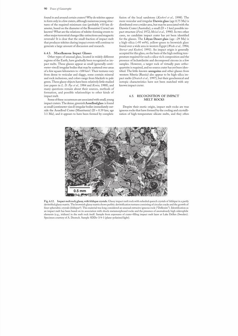
8/8/2019 Traces of Catastrophe - Book
http://slidepdf.com/reader/full/traces-of-catastrophe-book 101/130
90 Traces of Catastrophe
Fig. 6.12. Impact melt rock; glassy, with feldspar crystals. Glassy impact melt rock with euhedral quench crystals of feldspar in a partly devitrified glassy matrix. The brownish glassy matrix shows perlitic devitrification textures consisting of circular cracks and the growth of finer spherulitic crystals (feldspar?). This material was long considered an unusual extrusive igneous rock (“Dellenite”). Identification asan impact melt has been based on its association with shock-metamorphosed rocks and the presence of anomalously high siderophileelements (e.g., iridium) in the melt rock itself. Sample from exposures of crater-filling impact melt layer at Lake Dellen (Sweden).Specimen courtesy of A. Deutsch. Sample SDDe-3/4-1 (plane-polarized light).
found in and around certain craters? Why do tektites appearto form only in a few craters, although numerous young struc-tures of the required minimum size (probably >10 km di-ameter, based on the diameter of the Bosumtwi Crater) areknown? What are the relations of tektite-forming events toother major terrestrial changes like extinctions and magneticreversals? It is clear that the small fraction of impact meltthat produces tektites during impact events will continue to
generate a large amount of discussion and research.
6.4.3. Miscellaneous Impact GlassesOther types of unusual glass, located in widely different
regions of the Earth, have gradually been recognized as im-pact melts. These glasses appear as small (generally centi-meter-sized) irregular bodies that may be scattered over areasof a few square kilometers to >100 km2. Their textures vary from dense to vesicular and slaggy, some contain mineraland rock inclusions, and colors range from blackish to palegreen. These glassy objects have been relatively little studied(see papers in L. D. Pye et al., 1984 and Konta, 1988), andmany questions remain about their sources, methods of formation, and possible relationships to other kinds of impact melt.
Some of these occurrences are associated with small, youngimpact craters. The dense, greenish Aouelloul glass is foundas small (centimeter-sized) irregular bodies immediately out-side the Aouelloul Crater (Mauritania) (D = 0.39 km; age3.1 Ma), and it appears to have been formed by complete
fusion of the local sandstone (Koeberl et al., 1998). Themore vesicular and irregular Darwin glass (age 0.75 Ma) isdistributed over a wider area, but may be associated with theDarwin Crater (Australia), a small (D = 1 km) possible im-pact structure (Ford, 1972; Meisel et al., 1990). In two othercases, no candidate impact crater has yet been identifiedfor the glasses. The Libyan Desert glass (age ~29 Ma) isa high-silica (>95wt%), yellow-green to brownish glass
found over a wide area in western Egypt (Weeks et al., 1984;Storzer and Koeberl, 1991). An impact origin is generally accepted for this glass, on the basis of the high melting tem-perature required for such a silica-rich composition and thepresence of lechatelierite and decomposed zircons in a few samples. However, a target rock of virtually pure ortho-quartzite is required, and no source crater has yet been iden-tified. The little-known urengoites and other glasses from
western Siberia (Russia) also appear to be high-silica im-pact melts (Deutsch et al., 1997), but their geochemical andisotopic characteristics have not been matched with any known impact crater.
6.5. RECOGNITION OF IMPACTMELT ROCKS
Despite their exotic origin, impact melt rocks are trueigneous rocks that have formed by the cooling and crystalli-zation of high-temperature silicate melts, and they often
0.5 mm
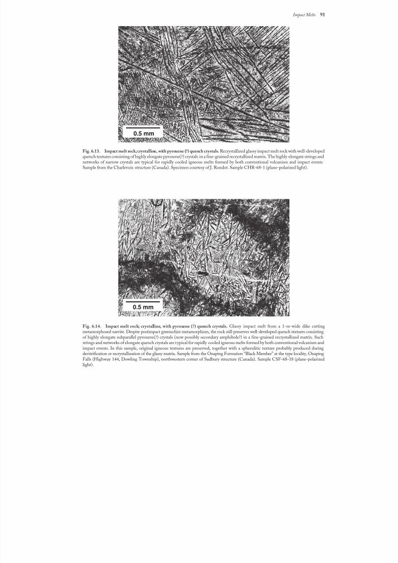
8/8/2019 Traces of Catastrophe - Book
http://slidepdf.com/reader/full/traces-of-catastrophe-book 102/130
Impact Melts 91
Fig. 6.13. Impact melt rock; crystalline, with pyroxene (?) quench crystals. Recrystallized glassy impact melt rock with well-developedquench textures consisting of highly elongate pyroxene(?) crystals in a fine-grained recrystallized matrix. The highly elongate strings andnetworks of narrow crystals are typical for rapidly cooled igneous melts formed by both conventional volcanism and impact events.Sample from the Charlevoix structure (Canada). Specimen courtesy of J. Rondot. Sample CHR-68-1 (plane-polarized light).
Fig. 6.14. Impact melt rock; crystalline, with pyroxene (?) quench crystals. Glassy impact melt from a 1-m-wide dike cuttingmetamorphosed suevite. Despite postimpact greenschist metamorphism, the rock still preserves well-developed quench textures consistingof highly elongate subparallel pyroxene(?) crystals (now possibly secondary amphibole?) in a fine-grained recrystallized matrix. Suchstrings and networks of elongate quench crystals are typical for rapidly cooled igneous melts formed by both conventional volcanism andimpact events. In this sample, original igneous textures are preserved, together with a spherulitic texture probably produced duringdevitrification or recrystallization of the glassy matrix. Sample from the Onaping Formation “Black Member” at the type locality, OnapingFalls (Highway 144, Dowling Township), northwestern corner of Sudbury structure (Canada). Sample CSF-68-18 (plane-polarizedlight).
0.5 mm
0.5 mm
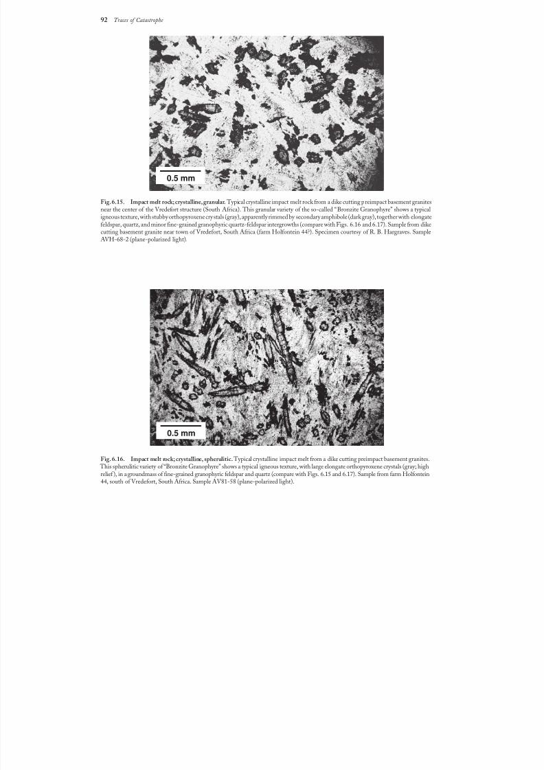
8/8/2019 Traces of Catastrophe - Book
http://slidepdf.com/reader/full/traces-of-catastrophe-book 103/130
92 Traces of Catastrophe
Fig. 6.15. Impact melt rock; crystalline, granular. Typical crystalline impact melt rock from a dike cutting preimpact basement granites
near the center of the Vredefort structure (South Africa). This granular variety of the so-called “Bronzite Granophyre” shows a typicaligneous texture, with stubby orthopyroxene crystals (gray), apparently rimmed by secondary amphibole (dark gray), together with elongatefeldspar, quartz, and minor fine-grained granophyric quartz-feldspar intergrowths (compare with Figs.6.16 and 6.17). Sample from dikecutting basement granite near town of Vredefort, South Africa (farm Holfontein 44?). Specimen courtesy of R. B. Hargraves. SampleAVH-68-2 (plane-polarized light).
Fig. 6.16. Impact melt rock; crystalline, spherulitic.Typical crystalline impact melt from a dike cutting preimpact basement granites. This spherulitic variety of “Bronzite Granophyre” shows a typical igneous texture, with large elongate orthopyroxene crystals (gray; highrelief ), in a groundmass of fine-grained granophyric feldspar and quartz (compare with Figs.6.15 and 6.17). Sample from farm Holfontein44, south of Vredefort, South Africa. Sample AV81-58 (plane-polarized light).
0.5 mm
0.5 mm
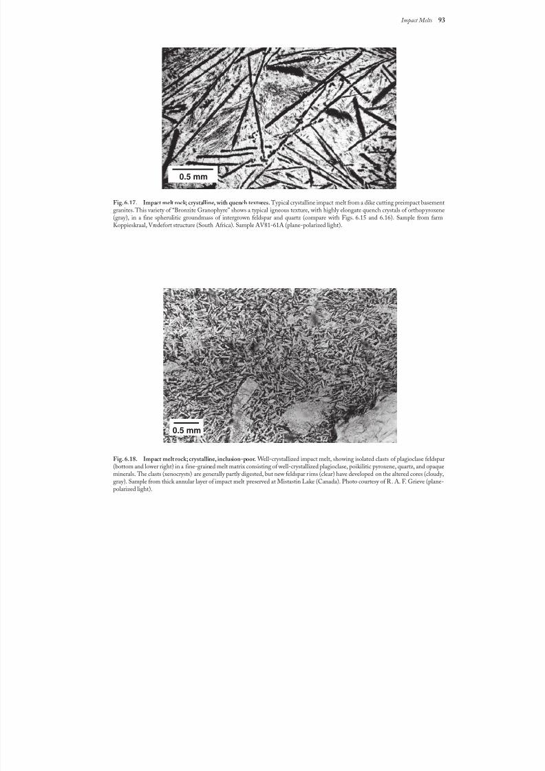
8/8/2019 Traces of Catastrophe - Book
http://slidepdf.com/reader/full/traces-of-catastrophe-book 104/130
Impact Melts 93
Fig. 6.17. Impact melt rock; crystalline, with quench textures. Typical crystalline impact melt from a dike cutting preimpact basement
granites. This variety of “Bronzite Granophyre” shows a typical igneous texture, with highly elongate quench crystals of orthopyroxene(gray), in a fine spherulitic groundmass of intergrown feldspar and quartz (compare with Figs.6.15 and 6.16). Sample from farmKoppieskraal, Vredefort structure (South Africa). Sample AV81-61A (plane-polarized light).
Fig. 6.18. Impact melt rock; crystalline, inclusion-poor. Well-crystallized impact melt, showing isolated clasts of plagioclase feldspar(bottom and lower right) in a fine-grained melt matrix consisting of well-crystallized plagioclase, poikilitic pyroxene, quartz, and opaqueminerals. The clasts (xenocrysts) are generally partly digested, but new feldspar r ims (clear) have developed on the altered cores (cloudy,gray). Sample from thick annular layer of impact melt preserved at Mistastin Lake (Canada). Photo courtesy of R. A. F. Grieve (plane-polarized light).
0.5 mm
0.5 mm
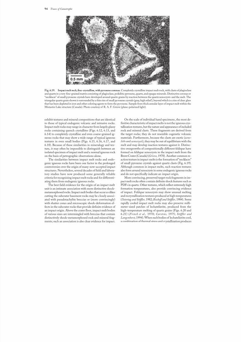
8/8/2019 Traces of Catastrophe - Book
http://slidepdf.com/reader/full/traces-of-catastrophe-book 105/130
94 Traces of Catastrophe
exhibit textures and mineral compositions that are identicalto those of typical endogenic volcanic and intrusive rocks.Impact melt rocks may range in character from largely glassy rocks containing quench crystallites (Figs.6.12, 6.13, and6.14) to completely crystalline and even coarse-grained ig-
neous rocks that may show a wide range of typical igneoustextures in even small bodies (Figs. 6.15, 6.16, 6.17, and6.18). Because of these similarities in mineralogy and tex-ture, it may often be impossible to distinguish between anisolated specimen of impact melt and a normal igneous rock on the basis of petrographic observations alone.
The similarities between impact melt rocks and endo-genic igneous rocks have been one factor in the prolongedcontroversies over the origin of many now-accepted impactstructures. Nevertheless, several decades of field and labora-tory studies have now produced some generally reliablecriteria for recognizing impact melt rocks and for differenti-ating them from endogenic igneous rocks.
The best field evidence for the origin of an impact meltunit is an intimate association with more distinctive shock-metamorphosed rocks. Impact melt bodies that occur as dikescutting the subcrater basement rocks may be closely associ-ated with pseudotachylite breccias or (more convincingly)
with shatter cones and microscopic shock-deformation ef-fects in the subcrater rocks that provide definite evidence of an impact origin. Above the crater floor, impact melt bodiesof various sizes are intermingled with breccias that containdistinctively shock-metamorphosed rock and mineral frag-ments; such an association is also clear evidence for impact.
On the scale of individual hand specimens, the most de-finitive characteristic of impact melts is not the igneous crys-tallization textures, but the nature and appearance of includedrock and mineral clasts. These fragments are derived fromthe target rocks; they do not resemble cogenetic volcanic
materials. Furthermore, because the clasts are exotic (xeno-liths and xenocrysts), they may be out of equilibrium with themelt and may develop reaction textures against it. Distinc-tive overgrowths of compositionally different feldspar haveformed on feldspar xenocrysts in the impact melt from theBrent Crater (Canada) (Grieve, 1978). Another common re-action texture in impact melts is the formation of “necklaces”of small pyroxene crystals against quartz clasts (Fig.6.19).Although common in impact melts, such reaction texturesalso form around xenocrysts in some endogenic igneous rocksand do not specifically indicate an impact origin.
More convincing, preserved target rock fragments in im-pact melt rocks often contain definite shock features such as
PDFs in quartz. Other textures, which reflect extremely highformation temperatures, also provide convincing evidenceof impact. Feldspar xenocrysts may show unusual meltingand recrystallization textures produced at high temperatures(Ostertag and Stöffler, 1982; Bischoff and Stöffler, 1984). Somerapidly cooled impact melt rocks may also preserve milli-meter-sized patches of lechatelierite, produced from thehigh-temperature melting of quartz grains (Figs. 6.20 and6.21) (French et al., 1970; Carstens, 1975; Stöffler and Langenhorst, 1994). When such bodies of lechatelierite cool,a combination of thermal stress and crystallization produces
Fig. 6.19. Impact melt rock; fine-crystalline, with pyroxene coronas. Completely crystalline impact melt rock, with clasts of plagioclaseand quartz in a very fine-grained matrix consisting of plagioclase, poikilitic pyroxene, quartz, and opaque minerals. Distinctive coronas or“necklaces” of small pyroxene crystals have developed around quartz grains by reaction between the quartz xenocrysts and the melt. Thetriangular quartz grain shown is surrounded by a thin rim of small pyroxene crystals (gray, high relief), beyond which is a rim of clear glassthat has been depleted in iron and other coloring agents to form the pyroxene. Sample from thick annular layer of impact melt within theMistastin Lake structure (Canada). Photo courtesy of R. A. F. Grieve (plane-polarized light).
0.5 mm
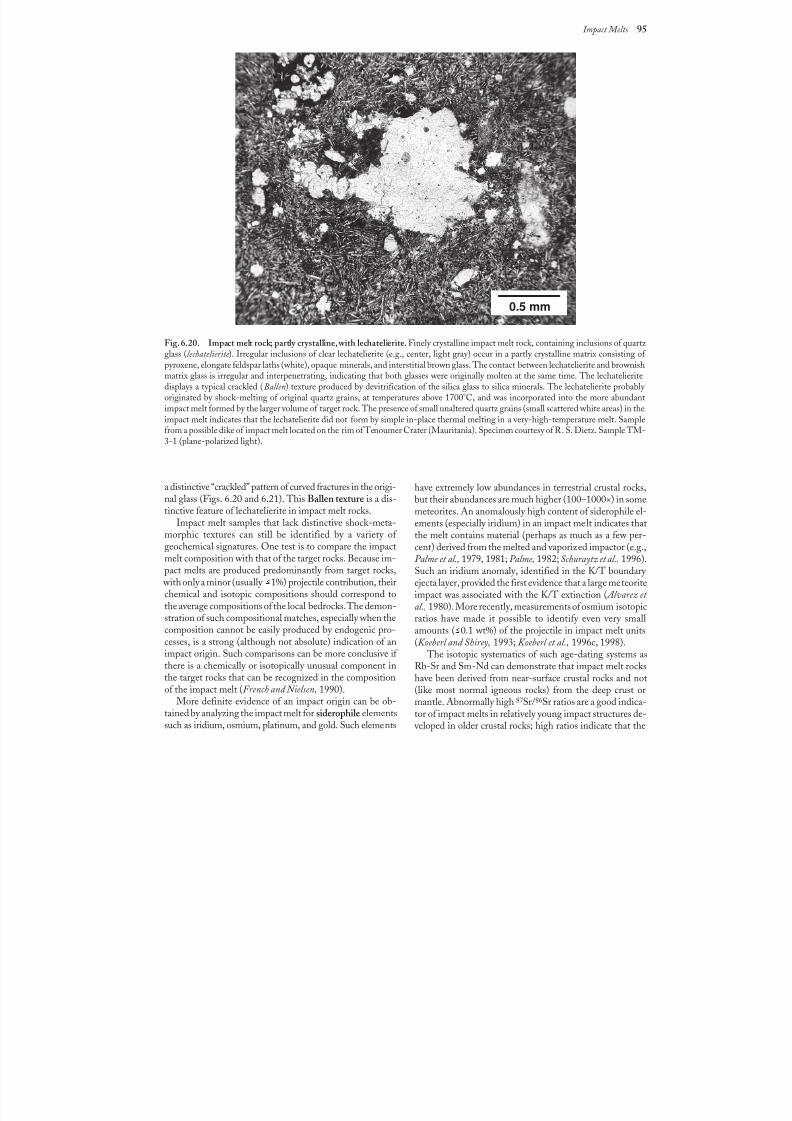
8/8/2019 Traces of Catastrophe - Book
http://slidepdf.com/reader/full/traces-of-catastrophe-book 106/130
Impact Melts 95
Fig. 6.20. Impact melt rock; partly crystalline, with lechatelierite. Finely crystalline impact melt rock, containing inclusions of quartz glass (lechatelierite ). Irregular inclusions of clear lechatelierite (e.g., center, light gray) occur in a partly crystalline matrix consisting of pyroxene, elongate feldspar laths (white), opaque minerals, and interstitial brown glass. The contact between lechatelierite and brownishmatrix glass is irregular and interpenetrating, indicating that both glasses were originally molten at the same time. The lechatelieritedisplays a typical crackled (Ballen) texture produced by devitrification of the silica glass to silica minerals. The lechatelierite probably originated by shock-melting of original quartz grains, at temperatures above 1700°C, and was incorporated into the more abundantimpact melt formed by the larger volume of target rock. The presence of small unaltered quartz grains (small scattered white areas) in theimpact melt indicates that the lechatelierite did not form by simple in-place thermal melting in a very-high-temperature melt. Samplefrom a possible dike of impact melt located on the rim of Tenoumer Crater (Mauritania). Specimen courtesy of R. S. Dietz. Sample TM-3-1 (plane-polarized light).
a distinctive “crackled” pattern of curved fractures in the origi-nal glass (Figs. 6.20 and 6.21). This Ballen texture is a dis-tinctive feature of lechatelierite in impact melt rocks.
Impact melt samples that lack distinctive shock-meta-morphic textures can still be identified by a variety of geochemical signatures. One test is to compare the impactmelt composition with that of the target rocks. Because im-pact melts are produced predominantly from target rocks,
with only a minor (usually >1%) projectile contribution, theirchemical and isotopic compositions should correspond to
the average compositions of the local bedrocks. The demon-stration of such compositional matches, especially when thecomposition cannot be easily produced by endogenic pro-cesses, is a strong (although not absolute) indication of animpact origin. Such comparisons can be more conclusive if there is a chemically or isotopically unusual component inthe target rocks that can be recognized in the compositionof the impact melt (French and Nielsen, 1990).
More definite evidence of an impact origin can be ob-tained by analyzing the impact melt for siderophile elementssuch as iridium, osmium, platinum, and gold. Such elements
have extremely low abundances in terrestrial crustal rocks,but their abundances are much higher (100–1000×) in somemeteorites. An anomalously high content of siderophile el-ements (especially iridium) in an impact melt indicates thatthe melt contains material (perhaps as much as a few per-cent) derived from the melted and vaporized impactor (e.g.,Palme et al., 1979, 1981; Palme, 1982; Schuraytz et al., 1996).Such an iridium anomaly, identified in the K/T boundary ejecta layer, provided the first evidence that a large meteoriteimpact was associated with the K/T extinction ( Alvarez et
al., 1980). More recently, measurements of osmium isotopicratios have made it possible to identify even very smallamounts ( >0.1 wt%) of the projectile in impact melt units(Koeberl and Shirey, 1993; Koeberl et al., 1996c, 1998).
The isotopic systematics of such age-dating systems asRb-Sr and Sm-Nd can demonstrate that impact melt rockshave been derived from near-surface crustal rocks and not(like most normal igneous rocks) from the deep crust ormantle. Abnormally high 87Sr/86Sr ratios are a good indica-tor of impact melts in relatively young impact structures de-
veloped in older crustal rocks; high ratios indicate that the
0.5 mm
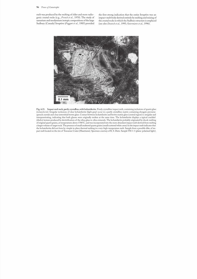
8/8/2019 Traces of Catastrophe - Book
http://slidepdf.com/reader/full/traces-of-catastrophe-book 107/130
96 Traces of Catastrophe
melt was produced by the melting of older and more radio-genic crustal rocks (e.g., French et al., 1970). The study of samarium and neodymium isotopic compositions of the largeSudbury (Canada) Irruptive (Faggart et al., 1985) provided
Fig. 6.21. Impact melt rock; partly crystalline, with lechatelierite. Finely crystalline impact melt, containing inclusions of quartz glass
(lechatelierite ). Irregular inclusions of clear lechatelierite (light gray) occur in a partly crystalline matrix containing elongate pyroxenequench crystals and clear interstitial brown glass. Contact between lechatelierite and brown matrix glass (central region) is irregular andinterpenetrating, indicating that both glasses were originally molten at the same time. The lechatelierite displays a typical crackled(Ballen) texture produced by devitrification of the silica glass to silica minerals. The lechatelierite probably originated by shock-meltingof original quartz grains, at temperatures above 1700°C, and was incorporated into the more abundant impact melt derived from meltinga larger volume of target rock. The presence of small unaltered quartz grains (small scattered white areas) in the impact melt indicates thatthe lechatelierite did not form by simple in-place thermal melting in a very-high-temperature melt. Sample from a possible dike of im-pact melt located on the rim of Tenoumer Crater (Mauritania). Specimen courtesy of R. S. Dietz. Sample TM-1-1 (plane-polarizedlight).
the first strong indication that the entire Irruptive was animpact-melt body derived entirely by melting and mixing of the crustal rocks in which the Sudbury structure is emplaced(see also Deutsch et al., 1995; Ostermann et al., 1996).
0.1 mm
8/8/2019 Traces of Catastrophe - Book
http://slidepdf.com/reader/full/traces-of-catastrophe-book 108/130
How to Find Impact Structures 97
97
7.1. REASONS FOR THE SEARCH
Since the 1960s, the field of meteorite impact geology has evolved far beyond the early arguments about the im-pact origin of a few individual geological structures. Mete-orite impacts on Earth are now widely accepted as animportant geological process, and one whose effects are stillnot fully understood. At the same time, the identificationof new impact structures through the discovery of shock-metamorphic effects has become a fairly simple and rou-
tine process. The current search for new impact structures now em-
phasizes the recognition, among the new discoveries, of in-dividual structures that can provide specific information aboutkey problems: shock-wave transmission, cratering mechan-ics, physical conditions of the impact environment, impact-melt formation, environmental and biological effects, andthe nature of the impact flux over geologic time. The lastproblem is especially uncertain and controversial, chiefly because relatively few impact structures have been accurately age-dated (Bottomley et al., 1990; Deutsch and Schärer, 1994).
The discovery and accurate dating of another 10–20 struc-tures might make it possible to estimate more accurately the
bombardment rate over time and to determine whether thebombardment process has been random or periodic.
For these reasons, the discovery and recognition of new terrestrial impact structures is still a critical component of future research in this field. To aid in this search, the re-mainder of this chapter summarizes the general propertiesof impact structures as they now appear on Earth, so thatnew candidates can be identified for detailed sampling andstudy (see also Appendix).
7.2. DETECTION OF CANDIDATEIMPACT SITES
The process of recognizing a new impact structure in- volves two steps: (1) detection of a candidate impact sitethrough field studies, geophysical measurements, remotesensing, drilling programs, or (sometimes) pure accident;and (2) verification of the site as an impact structure by thediscovery of shock-metamorphic effects in its rocks. (Insome cases, verification can also be provided by the dis-covery of meteorites or a meteoritic signature — such as
excess iridium — in the breccias or melt rocks associated with the structure.)
Many now-established impact structures first attractedattention because they appeared as anomalous circular fea-tures in topography or bedrock geology: lakes, rings of hills,or isolated circular areas of intense rock deformation in oth-erwise undeformed bedrock. A few impact structures devel-oped in sedimentary rocks were noted because the upturnedrocks of their central uplifts resembled salt domes, and theperceived economic potential promoted drilling and detailedgeophysical studies. Other impact structures have been foundby accident in the course of general field mapping or re-gional geophysical surveys. Some well-known structures [e.g.,
Ries Crater (Germany), Sudbury (Canada), and Vredefort(South Africa)] have been considered (often for many de-cades) as the sites of unusual volcanic activity or “crypto-
volcanic” events. And a few structures, so deeply eroded thatno circular form remains, have been recognized only by thepresence of scattered patches of unusual breccias or strange“volcanic” rocks.
The increasing appreciation of extraterrestrial impacts asa mainstream geological process, and the increasing atten-
How to Find Impact Structures
8/8/2019 Traces of Catastrophe - Book
http://slidepdf.com/reader/full/traces-of-catastrophe-book 109/130
98 Traces of Catastrophe
tion given to newly recognized impact structures, has pro-moted more searches for new structures as well as system-atic mapping of recognized structures by the sophisticatedmethods of remote sensing and geophysical surveys. How-ever, the discovery and verification stages still remain sepa-rate. A candidate impact structure may be detected in many
ways (field geology, remote sensing, geophysics), but verifi-cation comes only from the identification of definite im-
pact-produced features — shock-metamorphic effects,unique geochemical signatures, or both — in its rocks. Atpresent, there are no other geological or geophysical criteriathat unambiguously distinguish impact structures from othercircular features such as volcanic calderas, plutonic intru-sions, or salt domes. Definite proof of impact origin requiresaccess to the rocks. The candidate structure must first bedetected somehow, then it must be sampled.
7.2.1. Geological Features The first indication of a possible meteorite impact struc-
ture is frequently a distinct circular (or nearly circular) fea-ture in the topography or bedrock geology. This circularregion commonly shows distinctive and often anomalousbedrock geology in comparison to the surroundings. Theregion may also be the site of intense and localized deforma-tion (fracturing, faulting, and brecciation), or it may containunusual (or even normal-looking) volcanic or intrusive ig-neous rocks.
The distinctive features of impact structures vary withage and erosional history (Dence, 1972; Grieve, 1991; Grieve and Pilkington, 1996). In the few impact structures youngenough and fresh enough to still preserve their original cra-ter rims, the circular form may be striking. Original ejectaand shocked rock fragments may still be preserved on the
original ground surface outside the crater, and meteoritefragments may even be found to establish the origin of thestructure beyond question. In more deeply eroded structures,
where the original rim and outside ejecta have been removed,the circular outcrop pattern of breccias and melt rocks thatfilled the original crater may still attract attention. At deepererosion levels, where these rocks have been removed, a cir-cular pattern of intense deformation and brecciation, accom-panied in larger structures by a preserved central uplift, may still be recognizable, especially in structures formed in sedi-mentary rocks. In very deeply eroded structures, the circularcharacter may still be expressed by deformed or unusual rock types (e.g., pseudotachylite) in the bedrock, even when the
structure has been strongly deformed by postimpact tectonicactivity [e.g., Sudbury (Canada)].
A few impact structures have been so deeply eroded thatno distinctive circular feature remains. Such structures existonly as patchy remnants of unusual “volcanic” breccias andother deformed rocks, and in many cases [e.g., Rochechouart(France), Gardnos (Norway)] the shock effects (e.g., shattercones, PDFs in quartz) were only identified in the rocks de-cades after the rocks themselves had been first described.
The accumulated geological literature, especially papers thatdescribe strange breccias and unusual “volcanic” rocks, may
be a rewarding ground in which to search for unrecognizedimpact structures of this kind.
7.2.2. Geophysical Features The formation of impact structures involves shattering
and brecciation of the rocks that already exist beneath thecrater floor, followed by filling of the resulting crater by a
variety of impact-produced breccias and frequently by post-impact sediments. These processes produce distinctivechanges in the physical properties of the rocks in and aroundimpact structures. These changes are expressed most nota-bly as variations in the gravity and magnetic fields (Pilkingtonand Grieve, 1992; Grieve and Pilkington, 1996).
Gravity anomalies. Impact structures, even large ones, arerelatively shallow, near-surface features in comparison to typi-cal volcanic and tectonic structures. Even so, fracturing andbrecciation of the target rocks beneath an impact structureextend to significant depths below the crater floor, and sig-nificant fracturing and brecciation may even be present atdepths of several kilometers below large structures. Evidencefrom some studies, e.g., at Ries Crater (Germany), suggeststhat fracturing extends to depths of about one-third thediameter of the structure (e.g., 6–8 km at Ries Crater). Thefractured rock is less dense than the unaltered target rock around the structure, and the resulting density contrast may be increased by the similarly underdense fragmental brec-cias and sediments that fill the crater. As a result, many im-pact structures, especially bowl-shaped simple craters, exhibita negative gravity anomaly that is generally circular in shapeand closely coincides with the structural boundaries of thecircular feature.
Such a negative gravity anomaly is not a definite sign of
impact, and such anomalies are absent from many estab-lished impact structures. In complex impact structures, wheresubcrater fracturing and brecciation are accompanied by up-lift of denser deep-seated rocks into the central part of thestructure, the normal negative gravity anomaly may be re-duced or even converted to a positive anomaly, because theuplifted denser rocks overcome the effects of fracturing andbrecciation (Stepto, 1990; Pilkington and Grieve, 1992; Grieve and Pilkington, 1996).
Magnetic anomalies. Magnetic field measurements aroundimpact structures have not revealed any single specific sig-nature that can be clearly related to the impact process(Pilkington and Grieve, 1992). Some impact structures show
no significant magnetic signature because of the fragmenta-tion and mixing of target rock during the cratering process,and they may appear only as an anomalous circular region of low or random magnetic signature among any regional mag-netic patterns (e.g., linear anomalies) present in the surround-ing preimpact bedrock (Scott et al., 1997). At other impactstructures, a strong local magnetic anomaly (positive or nega-tive) may be produced by the remanent magnetization of units of impact melt within the structure or by the uplift of more magnetic units from depth into the central uplift (Hart et al., 1995).
8/8/2019 Traces of Catastrophe - Book
http://slidepdf.com/reader/full/traces-of-catastrophe-book 110/130
How to Find Impact Structures 99
Seismic studies. Seismic profiling studies are increasingly being used to determine the structural deformation presentbeneath large impact structures [e.g., Gosses Bluff (Austra-lia) ( Milton et al., 1972, 1996b); Montagnais (Canada) ( Jansaand Pe-Piper, 1987); Chesapeake Bay (USA) (Poag, 1996,1997); and Chicxulub (Mexico) ( Morgan et al., 1997)]. Thesestudies have revealed a pattern of subsurface deformationfeatures that appears distinctive for such impacts, especially
in the larger basin-form structures: (1) modest downwardand inward displacements of the rocks along the edges of the basin; (2) structural disruption, with no coherent seis-mic reflectors, in a central zone that corresponds approxi-mately to the region immediately beneath the central upliftand the original transient cavity; and (3) beneath this centralzone, evidence of preserved and continuous reflectors atdepth, demonstrating that the structure is shallow and hasno connecting roots to the lower crust or mantle. Seismicprofiles have also played an important role in demonstratingthe large size and complexity of the highly deformed Sudbury (Canada) structure (Wu et al., 1994).
Despite the complexities of geophysical features and thelack of unique signatures for impact structures, geophysicalmeasurements have been essential for the detection of impact structures that have been completely buried underlayers of younger sediments. The appearance of circularanomalies in gravity or magnetic surveys has already led tothe discovery of many verified subsurface impact structures,about one-third of the current known total (Grieve, 1991;Grieve and Masaitis, 1994; Grieve et al., 1995). Surprisingly large and important impact structures have been discoveredin this way: Puchezh-Katunki (Russia) (D = 80 km),Chicxulub (Mexico) (D > 180 km), the Chesapeake Bay Crater (USA) (D = 90 km), and Morokweng (South Africa)
(D>
70 km?).Geophysical studies will continue to play a critical role inthe future discovery and study of impact structures. Eventhough a well-defined circular geophysical anomaly can only indicate a possible impact structure, the discovery of suchanomalies has frequently been followed by verificationthrough core drilling, sample recovery, and the identifica-tion of distinctive shock effects or chemical signatures in therocks (e.g., Corner et al., 1997; Hart et al., 1997; Koeberl et al., 1997a). The combination of geophysical field studies andsubsequent core drilling is proving to be an important andeffective approach for detecting and verifying new impactstructures, and it is essential for detecting and exploring bur-
ied ones. Geophysical techniques also play an important andincreasing role in exploring established impact structures todetermine the details of their geology and formation.
7.3. VERIFICATION OF IMPACTSTRUCTURES
The brief history of impact geology suggests that most of the new impact structures identified in the future will benoted first as some kind of anomalous circular or near-cir-cular feature: (1) a circular or near-circular topographic or
physiographic surface pattern that can be detected by someform of remote sensing such as air photography or (increas-ingly more common) space-based imagery ; (2) a circular re-gion of anomalous exposed bedrock, characterized by intenseand localized deformation, uplift, breccia development, orby the occurrence of unusual “volcanic” rocks; or (3) a circu-lar geophysical anomaly, most probably in the gravity or mag-netic fields, associated with a surface or subsurface structural
feature. Rarer candidate sites that may be deeply erodedimpact structures may lack a circular signature and may ap-pear only as scattered exposures of anomalous rocks on theground or as descriptions in the geological literature.
Verification of an impact origin requires the discovery of unique impact-produced features. At present, the only gen-erally accepted impact features are shatter cones, petrographicshock effects, or distinctive geochemical signatures in therocks of the structure. Possible impact structures must there-fore be sampled by means of field studies, core drilling, orexamination of existing sample collections. In the field, well-developed and indisputable shatter cones are the best indi-cators of impact, because they are distinctive and widely distributed, especially in the basement rocks of deeply erodedstructures. Pseudotachylite breccias in basement rocks may indicate an impact origin, especially where they occur overlarge areas or in thick veins (e.g., >10 m), but they are not
yet accepted as a unique impact indicator because similarrocks can be produced by tectonic processes.
Rock samples can provide definite evidence of impact,often by applying only the straightforward and inexpensivemethods of standard petrography. Many distinctive shock effects can be identified even in small samples, such as piecesof drill core. The presence of PDFs in quartz is the most
widespread, distinctive, and generally accepted petrographic
shock criterion. They may occur in samples from two dis-crete regions in the structure: (1) in shocked-metamor-phosed rock fragments in crater-fill breccias and impactmelts; and (2) (more rarely) in preserved regions of shockedparautochthonous rocks just below the original crater floor,or in the central uplift, where PDFs may occur in or withshatter cones. Less common, but equally definitive, indica-tors of impact include diaplectic glasses (e.g., feldspar trans-formed to maskelynite), high-pressure mineral phases (e.g.,coesite, stishovite), and lechatelierite (fused quartz) in im-pact melts.
In breccias or melt rocks that display no shock features,geochemical analyses may provide definite evidence of im-
pact by identifying a signature from the projectile, eitherexcess iridium (or other platinum-group elements) or dis-tinctive osmium isotope ratios. Other geochemical signa-tures that strongly support an impact origin, but do notprovide definite proof, include: (1) a match in chemicaland/or isotopic compositions between the breccias and meltrocks and the target rocks in which the structure is found;and (2) isotopic signatures (e.g., Sm/Nd, Rb/Sr) in the meltrocks that indicate derivation entirely from crustal rocks(especially from crustal rocks much older than the structureitself ), without any mantle-derived component.
8/8/2019 Traces of Catastrophe - Book
http://slidepdf.com/reader/full/traces-of-catastrophe-book 111/130
What Next? Current Problems and Future Investigations 101
101
What Next?Current Problems and Future Investigations
8.1. IDENTIFICATION OF NEW IMPACT STRUCTURES
Despite the apparent abundance of impact structures(~150 now known), the terrestrial record remains both in-complete and biased, and it is essential to continue the search.
The present number of known impact structures is still >25% of the total presumably still preserved on the landareas of the Earth (Trefil and Raup, 1990; Grieve, 1991).Even worse, the processes of geological destruction activeon the Earth have strongly biased the observed distribution.
Most known impact structures have ages of <200 Ma, andsmall, easily eroded structures are strongly underrepresentedin the record (Grieve, 1991;Grieve and Pesonen, 1992, 1996).
The identification of more impact structures, accompa-nied by accurate age-dating, is essential to improve this data-base. With better data, we can explore some important andunanswered questions: What is the actual impact rate of
various-sized extraterrestrial objects on Earth? Is the bom-bardment rate variable, nonrandom, or even periodic? Whatare the relative importances of asteroids and comets as im-pacting bodies? With a larger suite of impact structures, it
will also be possible to identify well-preserved examples thatcan provide detailed information about cratering mechanics
and geological effects. Finding new impact craters is also achallenge to our abilities and our imaginations: How muchof the preserved impact record on Earth can we discover
with the techniques we now possess, and where are the piecesof this record located?
Current searches for new impact structures are now es-pecially active in Fennoscandia (Pesonen and Henkel, 1992;Pesonen, 1996), Africa (Koeberl, 1994b), and Australia(Glikson, 1996b; Shoemaker and Shoemaker, 1996). An im-portant component of these searches has been the discovery of subsurface impact structures from geophysical data (Cor-
ner et al., 1997; Hart et al., 1997; Gostin and Therriault, 1997).Until recently, the sea floor has been largely ignored in thesearch for impact structures, and only a few submarine im-pact structures have been identified (e.g., Jansa and Pe-Piper,1987; Poag, 1996; Dypvik et al., 1996). The special prob-lems of submarine impact structures are finally receiving at-tention. There is new interest in searching for impactstructures beneath the present oceans, and scientists are be-ginning to explore the unusual geology of submarine impactevents in a few impact structures that formed underwaterbut are now accessible on land (Therriault and Lindström,
1995; Lindström et al., 1996). Even so, all the submarinestructures so far identified have formed on the shelf areas of adjacent continents. The deep ocean basins, which probably received about three-quarters of the projectiles that struck Earth in the last ~200 m.y., still remain to be explored, al-though evidence for one recent small impact in the SouthPacific has been discovered (Gersonde et al., 1997). Amidthis current activity on sea and land, the search for the sourcecrater that produced the Australasian tektite strewnfield re-mains a prominent and nagging problem for the future.
8.2. IMPACT EVENTS AND EXTINCTIONS
A firm connection between one large impact event andone major biological extinction has now been solidly estab-lished between the Chicxulub structure (Mexico) and theK/T event ( Alvarez et al., 1980; Sharpton et al., 1992; papersin Ryder et al., 1996; Alvarez, 1997). Research on the K/Tproblem has now largely turned away from debating the ex-istence of the impact and is now focused on closer studies of the consequences. Paleontologists are studying the finer de-tails of the extinction itself: the duration of the overall event,the relative timing of the disappearances of different spe-
8/8/2019 Traces of Catastrophe - Book
http://slidepdf.com/reader/full/traces-of-catastrophe-book 112/130
102 Traces of Catastrophe
cies, and the various environmental stresses and “kill mecha-nisms” implied by the geological record.
At the same time, a major geological effort, involvinggeophysical surveys and new drilling projects (e.g., Sharptonet al., 1993, 1996b; Morgan et al., 1997), is concentrating onthe Chicxulub structure itself, to determine more accurately the size of the structure, the energy released by the impact,and the amounts of volatile materials (water vapor, CO2 and
SO2) released from melted and vaporized target materials(ocean water, limestones, and evaporites) (papers in Ryder et al., 1996; Pope et al., 1994, 1997; Yang and Ahrens, 1998).
These data are needed to accurately estimate the global en- vironmental stress and to complement the paleontologicalstudies of the extinction. In addition to its tie to the K/Textinction, the Chicxulub structure itself, because of its rela-tive youth and immediate burial after formation, is the best-preserved terrestrial impact structure of its size discoveredto date, and the geological studies will also yield a wealth of information about the cratering mechanics and geologicaleffects involved in such large, rare impact events.
Despite the strength of the connection between Chicxuluband the K/T extinction, it has not yet proved possible toestablish a similar firm link between an impact event andany of the half-dozen or so other major extinctions recordedin the last 700 m.y. However, there are growing indicationsof a link between impact events and the lesser extinctionobserved about 35 m.y. ago near the Eocene-Oligoceneboundary ( Montanari et al., 1993; Clymer et al., 1996;Langenhorst and Clymer, 1996; Glass et al., 1998). All theessential ingredients seem to be present: a significant ex-tinction, a layer of impact debris (including microtektites)at the boundary, and two candidate impact structures inthe >90-km-diameter range: Popigai (Russia) (Bottomley et
al., 1997) and Chesapeake Bay (USA) (Koeberl et al., 1996a).A layer containing shocked quartz has also been found atthe older (205 Ma) Triassic-Jurassic boundary, a locationalso characterized by a major biological extinction (Bice et al., 1992).
8.3. DISTAL IMPACT EJECTA
An important and unexpected resource for future studiesof terrestrial impacts are the thin layers of distal ejecta thatare distributed over continental to global distances from theimpact site. In the past, it was considered unlikely that such
thin deposits could be preserved in the geologic record, andlittle consideration was given to finding and identifying them.
This attitude has changed drastically, chiefly as a result of studies at the K/T boundary, where the distinctive globalejecta layer from the Chicxulub impact structure was con-clusively identified even before the structure itself was lo-cated. Distal ejecta layers have also been identified from otherstructures, e.g., Manson (Iowa) and Acraman (Australia),and it is now generally accepted that microtektite layers alsorepresent distal ejecta.
Although only a few distal ejecta layers from particularstructures have been identified so far, the potential impor-
tance of such layers has been increased by new methods of study and analysis. Layers of impact-crater ejecta can now be clearly distinguished from similar sedimentary or volca-nic units (e.g., ash-fall beds) by the presence of such uniquefeatures as spherules, quartz PDFs, and iridium anomalies.Current geochemical techniques are sensitive and preciseenough — even if delicate and time-consuming — to ex-tract important information about the impact event from
small particles, and it is possible, in many cases, to deter-mine from a small sample of ejecta the age of the impact orthe geochemical characteristics of the target rock involved.
Distal ejecta layers in the sedimentary record have a largeand unexplored potential to provide critical insights into theimpact history of the Earth (Grieve, 1997). Systematic iden-tification of distal ejecta layers in long-duration sedimentary sections can yield independent estimates of the impact rateover geologic time. Ejecta layers linked to known large im-pact structures can improve our understanding of the craterformation process and the areal extent of the environmentaleffects. In some cases, it may be possible to obtain good age-dates on impact events from the stratigraphic ages of theejecta. Some individual ejecta layers may also indicate theexistence of unsuspected and undiscovered impact structures,as was the case with the Chicxulub structure and for a LateDevonian impact event recently recognized in the westernUSA (Leroux et al., 1995).
8.4. CARBON CHEMISTRY IN THEIMPACT ENVIRONMENT
The uniqueness of the high-pressure shock-wave envi-ronment below the developing impact crater has long been
appreciated, but there are recent indications that equally unique conditions above the impact point also produce un-usual and lasting effects. At the moment of impact, a high-temperature vapor plume, with temperatures of thousandsof degrees, expands outward and upward from the impactpoint ( Melosh, 1989, pp. 68–71). This plume, as it interacts
with the atmosphere, plays a major role in ejecting materialfrom the crater to great distances (e.g., Alvarez et al., 1995).
This extreme environment also produces a variety of un-usual and still-baffling chemical changes.
Carbon compounds in impactites have recently revealeda variety of exciting and puzzling features, some of whichmay reflect the instantaneous high-temperature environment
within the vapor plume. Diamonds have long been knownto be a shock-metamorphic product in carbon-bearing tar-get rocks (e.g., Masaitis, 1998; Masaitis et al., 1972; Koeberl et al., 1997c), but more recent studies have discovered tiny nanodiamonds, unrelated to preimpact target graphite, thatapparently formed in the vapor phase and then were depos-ited in suevite breccias (Hough et al., 1995) and in ejectaat the K/T boundary (Carlisle and Braman, 1991; Houghet al., 1997).
A different form of carbon, fullerenes, has also been dis-covered in terrestrial impact environments. These recently discovered “soccer-ball” carbon molecules (e.g., the C60 mol-
8/8/2019 Traces of Catastrophe - Book
http://slidepdf.com/reader/full/traces-of-catastrophe-book 113/130
What Next? Current Problems and Future Investigations 103
ecules called “buckyballs”) have attracted attention becauseof their stability and unusual chemical characteristics (e.g.,the ability to “cage” other atoms) (for background and de-tails, see Aldersey-Williams, 1995). Because of their stability,it has been suggested that fullerenes could form in the out-flows from high-carbon stars and could be common in boththe interstellar medium and in meteorites, although fullereneshave not yet been conclusively identified in either location.
However, fullerenes have been identified in the K/T ejectalayer (Heymann et al., 1994) and in the carbonaceousOnaping Formation, an impact breccia at the Sudbury struc-ture (Canada) (Becker et al., 1994, 1996). The presence of fullerenes in such impact-produced deposits, their possibleextraterrestrial origin, and the implications of their presencefor the origins of life on Earth have focused considerablemultidisciplinary attention, particularly from exobiologists,on impact processes in general and Sudbury in particular.
Carbon in impact structures, and its behavior during im-pact events, is an area of research that currently contains afew exciting observations, enclosed in a large number of un-answered questions. Carbon is generally absent in impactstructures; impactites with significant carbon contents(>0.5wt%) are known only from Sudbury (Canada) (French,1968b; Avermann, 1994) and Gardnos (Norway) (French et al., 1997). The source(s) of this carbon has not been estab-lished; possible sources are the projectile (e.g., carbonaceouschondrite meteorites or comets), Earth’s atmosphere, or yet-unrecognized carbonaceous target rocks. It is also possiblethat the carbon has been introduced into the impactites dur-ing later metamorphism. Identifying the sources of carbonin these impactites, and distinguishing between impact-re-lated and postimpact carbon, requires careful sampling andsophisticated analyses in the future.
The problem of carbon in the impact environment leadsdirectly to large and longstanding questions about the originof the solar system, the formation of planets, and the originand history of life on Earth. Are any carbon and organicmolecules present in the incoming projectile destroyed by the impact event, or can they survive to contribute to thesubsequent origin of life? What does the formation and sur-
vival of diamonds and fullerenes in impact events tell us aboutthe physical conditions in the vapor plume or the nature of Earth’s atmosphere at the time of impact? Impact structures,especially those with carbonaceous impactites, preserve theresults of unique natural experiments in prebiotic chemistry and the behavior of carbon compounds under extreme con-
ditions. Interdisciplinary studies to explore these problemsshould be an important part of future impact studies.
8.5. POSTIMPACT PROCESSES AND EFFECTS
Past research on impact events has concentrated on theformation of the impact structure and its immediate ef-fects: shock-metamorphic features, generation of impactmelts, and biological extinctions. It is now recognized thatthe large amounts of mechanical and thermal energy depos-
ited in the impact site produce longer-term effects, and thereis new interest in identifying and studying impact effectsthat persist during the period (102–106 yr) in which normalgeological processes resume in the region affected by theimpact event.
The thermal energy deposited in an impact structure asshock heating and impact-melt formation can produce hy-drothermal activity and related ore deposits similar to those
that result from more conventional geological processes. Suchpostimpact activity is frequently expressed in the secondary alteration of the impact melts themselves (Dence, 1971; Newsom et al., 1986; McCarville and Crossey, 1996). How-ever, in larger structures, the combination of large volumesof melt and extensive hydrothermal circulation may producenew sedimentary deposits and associated ore bodies, e.g.,the Vermillion Formation at Sudbury (Canada) (Grieve and Masaitis, 1994).
The postimpact sediments that fill some impact struc-tures may preserve a record of the important transition be-tween impact-related effects and postimpact geologicalhistory. At the buried Chicxulub structure (Mexico), the thick crater-fill deposits have a special importance because they may preserve the immediate postimpact history of waningimpact effects and biological recovery after the K/T event.At other impact sites, crater-fill sediments may preserve theonly available long-term record of postimpact geological andenvironmental processes that originally affected a much widerregion (Beales and Lozej, 1975; Partridge et al., 1993; Grieve,1997).
The overall shape and general geological characteristicsof impact structures have been well established by extensiveresearch, and these features can serve as important markersfor determining postimpact erosion and deformation (Grieve,
1991). This knowledge is also important for identifying andreconstructing highly deformed impact structures, such asSudbury (Canada) (Wu et al., 1994), in which the presently preserved feature may represent only a fraction of the size of the original impact structure (Therriault et al., 1997).
8.6. PETROGENESIS OF IGNEOUS ROCKS:IMPACT MELTS
The impact melt rocks preserved in terrestrial impactstructures represent unique, important, and virtually unstud-ied laboratory experiments in the formation, emplacement,
and crystallization of igneous rocks. Future studies of impact melts can provide unique insights into these long-standing geological problems. Impact melt bodies occur in arange of sizes, from small and rapidly cooled pods and dikesup to the huge Sudbury Irruptive with its associated ore de-posits. These bodies have formed, nearly instantaneously, ina single melting event, from surrounding target rocks thatcan generally be sampled and characterized. The largest andbest-preserved impact melt bodies are found as sills in thecrater-fill deposits, and they have cooled uniformly withoutany addition of new magma. Their history and cooling envi-ronment can be well constrained by information about the
8/8/2019 Traces of Catastrophe - Book
http://slidepdf.com/reader/full/traces-of-catastrophe-book 114/130
104 Traces of Catastrophe
crater shape and the impactite deposits associated with them.As igneous rocks, impact melts provide a degree of simplic-ity, information, and context that is only rarely found in en-dogenic igneous rocks, and study of them will providefundamental information on all igneous rocks.
Detailed comparative studies of terrestrial impact meltrocks and endogenic igneous rocks can also improve currentmodels for impact crater formation and impact melt genera-
tion. Is the current assumption that impact melt bodies arehomogeneously mixed target rock really correct at all scales?Is there time for chemical and mineralogical differentiationin large bodies of impact melt (e.g., the Sudbury Irruptive),or do the systematic variations observed have some othercause? What can terrestrial impact melts tell us about theorigin and chemistry of the very large bodies of impact meltassociated with the largest lunar impact basins?
8.7. IMPACTS AND THE EARLY EARTH
Even the largest and oldest known terrestrial impact struc-tures [Sudbury (Canada) and Vredefort (South Africa)] areonly about 2 b.y. old and were only about 200–300 km indiameter when they formed. They are therefore both smalland young by comparison with the earlier history of impactevents in the solar system. Preserved impact features on theMoon, Mercury, and other planets exceed 1000 km indiameter and are >4 b.y. old, and the ancient and heavily cratered surfaces of the Moon and other planets show thatthis period was a time of intense bombardment, when im-pact rates were hundreds to thousands of times the presentlow values (Fig.1.13) (Taylor, 1975; 1982, Chapter 3; 1992,Chapter4; Hörz et al., 1991; Spudis, 1993).
Earth could not have escaped the heavy bombardment of extraterrestrial objects at this time, and the present scarcity of old and large terrestrial impact structures reflects the con-tinuous geological destruction and recycling of old terres-trial rocks. We therefore face a major problem in exploringthe impact history of Earth: Just when impact events be-come more frequent, larger, and potentially more important(>3.8 Ga), the available record of these events becomes in-creasingly destroyed. Are Sudbury and Vredefort the largestand oldest impact structures that we can find preserved onEarth? Or can we find the traces of larger and more ancientimpact events and understand their effects?
The evidence from other planets leaves no doubt that large
impacts on Earth were not only a major, but in fact the domi-nant, process during early geologic time (>3.8 Ga). Com-parisons with the lunar highlands (Grieve, 1980; Grieve et al., 1990) suggest that as many as 200 impact basins>1000 km in diameter may have formed on Earth duringthis period, accompanied by exponentially larger quantitiesof smaller structures. Plausible geological effects of thesecatastrophes include the formation of huge volumes of im-pact melts, the triggering of widespread endogenic volcan-ism from beneath a thin Archean crust, and the creation of early continental nuclei (Frey, 1980; Grieve, 1980; Glikson,
1993, 1996a). The effects above ground could be equally di-sastrous. Large impacts could blast away existing atmos-pheres and then replace them with water and other volatilescarried in the projectiles themselves. The development of life on Earth could have followed an intermittent path in
which existing life forms were destroyed by large impactsand new ones formed from the organic compounds broughtin by the projectiles. Even in relatively recent times (>2.5Ga),
sporadic large impacts could have produced major changesin the igneous and tectonic histories of Earth (Glikson, 1993,1996a).
The search for traces of such events faces several prob-lems. The old rocks that would preserve them are scarce andoften highly metamorphosed, making it difficult to distin-guish impact effects from the results of normal geologicalprocesses (e.g., Weiblen and Schulz, 1978). A second prob-lem is uncertainty about what very large impact structures
would look like, even if well preserved. Larger impact struc-tures (D > 200–300 km) will generate relatively largeramounts of melt, producing a wide, relatively shallow struc-ture dominated by melt rather than by more familiar impactitebreccias (Grieve and Cintala, 1992; Cintala and Grieve, 1998).Such structures might easily be removed by erosion or mis-taken for endogenic bodies such as sills and lopoliths. Thepossibility that the well-known Bushveld Complex (SouthAfrica) might be such a melt-rich impact structure (Rhodes,1975) has so far proved to be negative (e.g., French, 1990a),but the debate and the searches go on.
Despite these difficulties, it may still be possible to rec-ognize the traces of ancient impact events. Distinctive shock features such as shatter cones and pseudotachylite brecciascan be preserved in even highly metamorphosed rocks, ascan distinctive geochemical signatures (e.g., iridium anoma-
lies) in breccias and impact melts. It may also be possible torecognize distal ejecta units from ancient impact events, andsuch an origin has been proposed for the unusual spherulelayers found in >3-b.y.-old rocks of the BarbertonMountainLand (South Africa) (Lowe and Byerly, 1986; Lowe et al.,1989) and in 2.6-b.y.-old sediments in Australia (Simonson,1992; Simonson and Davies, 1996; Simonson et al., 1997).Definite shock-metamorphic effects have not yet been foundin these spherule beds, and their origin is still debated (e.g.,French, 1987; Koeberl et al., 1993; Koeberl and Reimold, 1995),but the mere preservation of such distinctive units in suchancient rocks is an encouraging sign for future searches.
A related possibility, speculative and exciting, is that even
thicker (10–100 m) layers of ejecta from large impact struc-tures may be preserved among the long-studied formationsof diamictites, unusual breccias currently regarded as theproducts of glacial activity or other unusual sedimentationprocesses (Oberbeck et al., 1993; Rampino, 1994). These unitsare an important target for future searches, and they shouldbe examined anew for shock-metamorphic effects (e.g.,Reimold et al., 1997b).
The increasing importance of meteorite impacts in Earthhistory, the growing recognition of preserved impact effectsin the geological record, and the ease with which impact

8/8/2019 Traces of Catastrophe - Book
http://slidepdf.com/reader/full/traces-of-catastrophe-book 115/130
What Next? Current Problems and Future Investigations 105
events can be recognized by their shock-metamorphic ef-fects have combined to show geologists the importance of new searches in the field. In the future, as geologists dis-cover more ancient rocks, or as they reexamine formationsdiscovered long ago, the possibilities of impact — and thekey signatures of impact events — should be kept in mind.
During the brief history of meteorite impact geology, allpast predictions about the importance of impacts and the
range of their effects have turned out to be inaccurate andunimaginative underestimates. Although a lot has beenlearned in the last couple of decades, there is no reason toexpect that today’s estimates will turn out to be any moreaccurate. We must now do what geologists have always done
when suddenly faced with ideas that are new, exciting, poorly explored, and only dimly understood. We must take the new ideas out into the field and look at the rocks again.

8/8/2019 Traces of Catastrophe - Book
http://slidepdf.com/reader/full/traces-of-catastrophe-book 116/130
106 Traces of Catastrophe
8/8/2019 Traces of Catastrophe - Book
http://slidepdf.com/reader/full/traces-of-catastrophe-book 117/130
Appendix 107
107
Appendix
* Indicates unique shock-metamorphic features that provide definite evidence for meteorite impact origin.
1. SURFACE FORM AND GEOLOGIC STRUCTURE
Surface Expression and Shape:occur in any kind of bedrock (crystalline, sediments, volcanic)generally occur as single structures
rarely double or small multiple structureslarger structures not present as groups
generally circularelliptical or noncircular in deformed structures
possible circular depression or definite crateralso possible circular uplifted region
may be expressed by physiographic features (e.g., topographic relief, drainage)
Size and Occurrence: wide size range, from <1 km to >100 km diameteroccur in all geological terranes, bedrock (crystalline, sediments, volcanic)only random association with other geological features
Relatively shallow underlain by undeformed regional bedrock unusual deformation extends less than one-third apparent diameter
Anomalous feature in regional topography, geology unusual geology within circular arealocal deformation: faulting, brecciationunusual breccias, melt rocks within structure
serve to define structuremay be absent (deeply eroded structures)similar breccias rarely present outside structure
deposits on or beyond rimin structures with well-defined crater morphology
central uplift of deeper-seated rocks (in larger structures)may form central peak or central ringshow definite stratigraphic upliftrocks may contain distinctive shatter cones*
unique conical fractures, striated
restored apexes point inward/upward
Vague or ambiguous descriptions in previous literaturedeformation recognized in earlier studies (intense, sudden, localized)conventional endogenic mechanisms not adequate
vague mechanisms proposedunusual volcanic explosions(“cryptoexplosions”)
CRITERIA FOR RECOGNIZING TERRESTRIALIMPACT STRUCTURES
(expanded from Dence, 1972, pp. 78–79, and other sources)
8/8/2019 Traces of Catastrophe - Book
http://slidepdf.com/reader/full/traces-of-catastrophe-book 118/130
108 Traces of Catastrophe
* Indicates unique shock-metamorphic features that provide definite evidence for meteorite impact origin.
CRITERIA FOR RECOGNIZING TERRESTRIALIMPACT STRUCTURES
1. SURFACE FORM AND GEOLOGIC STRUCTURE (continued)
Brecciation: may be widespread in surface, subsurface samplesbreccia zones in bedrock below crater
around rims or in central uplift areasgenerally in-place monomict brecciasrare dike-like bodies of polymict breccia, meltunusual pseudotachylite breccias
polymict breccias and melt rocksmay form blanket-like, layered units (crater fill)in central regions (small structures)as annular units around central uplifts (larger structures)
2. GEOPHYSICAL CHARACTERISTICS
Gravity Signature:may show circular anomaly following structuretypically negative (breccias and sedimentary fill)may be positive (larger structures; uplift)may also be lacking
Magnetic Signature:no distinctive typical patternregional anomalies outside structure may be interrupted, subdued, merged
within structuremay be positive anomalies over specific areas
melt-bearing rocks, brecciasuplifted deep-seated magnetic rocks
Seismic Characteristics:lower seismic velocities within structure
(from brecciation; presence of sedimentary fill)regional stratigraphy interrupted by structure
deep seismic reflectors disrupted; chaotic patternregional structure again becomes continuous at relatively shallow depths
beneath surface structureno evidence of deep roots or connections for structure
around margins, presence of concentric shallow inward faults, producingterraced rims
3. ROCK TYPES: GENERAL CHARACTERISTICS
Monomict Breccias:abundance, distribution reflect nature of bedrock
(homogeneous/heterogeneous)areas within bedrock below, around structurelayers in units that fill structureno abnormal deformation in component clastsbulk chemical compositions are those of associated local bedrock no siderophile-element anomalies (iridium contents, osmium isotopes)

8/8/2019 Traces of Catastrophe - Book
http://slidepdf.com/reader/full/traces-of-catastrophe-book 119/130
Appendix 109
* Indicates unique shock-metamorphic features that provide definite evidence for meteorite impact origin.
CRITERIA FOR RECOGNIZING TERRESTRIALIMPACT STRUCTURES
3. ROCK TYPES: GENERAL CHARACTERISTICS (continued)
Polymict Breccias:occurrence: various possible locations:
intrusive dike-like bodies in bedrock irregular horizontal layers within structure
(may be transitional with melt rocks)along/outside rim of structure (ejecta)
rare: only in well-preserved structuresrock fragments: derived from local bedrock only
exotic rock types rare to absentboth melt-bearing and melt-free varieties present
melt-bearing: diverse types:melt as discrete fragments; clastic matrixmelt-matrix, with bedrock clasts
melt-bearing types:
resemble endogenic volcanic breccias, e.g., ash-flow tuffs, intrusive brecciaslack typical volcanic featuresno phenocrysts, cogenetic volcanic rocksall fragments are broken bedrock clasts
may contain distinctive cored inclusions(melt rim around bedrock clast)
breccia units appear deposited all at onceno evidence for prolonged volcanic activity no erosional horizons observed between units
bedrock inclusions often show unusual, distinctive petrographic deformationfeatures
bulk chemical compositions equivalent to compositions of mixed localbedrock types
siderophile-element anomalies* may be present(iridium contents, osmium isotopes)
Melt Rocks:occur in diverse locations
dike-like bodies in substructure bedrock sill-like units within structure
interbedded with brecciasdisplay range of typical igneous textures
features reflect size, cooling ratetransitional with melt-bearing brecciasincluded rock fragments often display unusual petrographic deformation,
melting, and recrystallization textures
bulk chemical compositions equivalent to compositions of mixed localbedrock types
may show siderophile-element anomalies*(iridium contents, osmium isotopes)

8/8/2019 Traces of Catastrophe - Book
http://slidepdf.com/reader/full/traces-of-catastrophe-book 120/130
110 Traces of Catastrophe
CRITERIA FOR RECOGNIZING TERRESTRIALIMPACT STRUCTURES
4. MICROSCOPIC DEFORMATION AND MELTING FEATURES
Found in a variety of rock types and locations in structure(1) in-place bedrock in center of structure
(rarely preserved or exposed)may be associated with shatter cones*
(2) bedrock inclusions in polymict breccias and melt rocksNot present in rim bedrock or monomict breccia clasts
General characteristics of deformationquartzofeldspathic rocks most sensitive, best indicatorsselective: each mineral responds in isolation pervasive: generally affects each mineral grainlocally variable: strong differences in deformation intensity over small areas
may be small local glassy veins, pods in rock range of effects: progressive deformation, melting
progressive destruction of original fabric
Fracturing (may not be distinguishable from effects of other geological processes)intense, closely spaced parallel sets may be shock-producedmay be associated with definite shock-deformation features
Unique mineral deformation features (shock-produced)planar deformation features (PDFs)* in quartz, feldspar
multiple sets at distinct orientationsmay be fresh (continuous) or “decorated” (inclusions)Brazil twins parallel to base (0001)
diaplectic glasses*, e.g. maskelynite (feldspar)high-pressure mineral phases*:
coesite, stishovite, diamond
Selective mineral melting * of specific minerals in rock individual minerals melt; associated minerals not affectedmelted minerals may show incipient flow, vesiculationtransitions to completely melted rock fragments, heterogeneous glasses
Unusual (high-temperature) melting effects* in rock fragmentsmelting, decomposition of normally refractory minerals
e.g., zircon, sphene* (T > 1400°–1700°C)quartz → lechatelierite* (T > 1713°C)
evidence of rapid quenching, disequilibrium
Unusual heterogeneous glass fragments (e.g., Fladen)mixed rock /mineral fragments in heterogeneous glassincluded rock /mineral clasts show range of unusual deformation,
melting effectslechatelierite* bands, strings (schlieren) present in flow-banded glassstrong indications of disequilibrium, rapid quenching
Deformation, melting textures:show modification or complete destruction by later processes(secondary recrystallization, hydrothermal activity, metamorphism)
* Indicates unique shock-metamorphic features that provide definite evidence for meteorite impact origin.
8/8/2019 Traces of Catastrophe - Book
http://slidepdf.com/reader/full/traces-of-catastrophe-book 121/130
References 111
111
Ahrens T. J. (1993) Impact erosion of terrestrial planetary atmos-pheres. Annu. Rev. Earth Planet. Sci., 21, 525–555.
Ahrens T. J. and O’Keefe J. D. (1977) Equations of state andimpact-induced shock-wave attenuation on the Moon. In Impact and Explosion Cratering: Planetary and Terrestrial Implications (D. J. Roddy, R. O. Pepin, and R. B. Merrill,eds.), pp. 639–656. Pergamon, New York.
Aldersey-Williams H. (1995) The Most Beautiful Molecule: The Discovery of the Buckyball. John Wiley and Sons, New York.340 pp.
Alexopoulos J. S., Grieve R. A. F., and Robertson P. B. (1988)Microscopic lamellar deformation features in quartz: Dis-criminative characteristics of shock-generated varieties.Geology, 16, 796–799.
Alvarez L. W., Alvarez W., Asaro F., and Michel H. V. (1980)Extraterrestrial cause for the Cretaceous-Tertiary extinction.Science, 208, 1095–1108.
Alvarez W. (1997) T. Rex and the Crater of Doom. Princeton Univ.,Princeton. 185 pp.
Alvarez W., Claeys P., and Kieffer S. W. (1995) Emplacementof Cretaceous-Tertiary boundary shocked quartz fromChicxulub crater. Science, 269, 930–935.
Arndt J., Hummel W., and Gonzalez-Cabeza I. (1982) Diaplecticlabradorite glass from the Manicouagan impact crater. I.Physical properties, crystallization, structural and geneticimplications. Phys. Chem. Minerals, 8, 230–239.
Avermann M. (1994) Origin of the polymict, allochthonousbreccias of the Onaping Formation, Sudbury structure,Canada. In Large Meteorite Impacts and Planetary Evolution(B. O. Dressler, R. A. F. Grieve, and V. L. Sharpton, eds.),pp. 265–274. Geol. Soc. Am. Spec. Paper 293.
Baldwin R. B. (1949) The Face of the Moon. Univ. of Chicago,Chicago. 239 pp.Baldwin R. B. (1963) The Measure of the Moon. Univ. of Chicago,
Chicago. 488 pp.Beales F. W. and Lozej G. P. (1975) Ordovician tidalites in the
unmetamorphosed sedimentary fill of the Brent MeteoriteCrater, Ontario. In Tidal Deposits, A Casebook of Recent Examples and Fossil Counterparts (R. N. Ginsburg, ed.),pp. 315–323. Springer-Verlag, New York.
Beals C. S., Innes M. J. S., and Rottenberg J. A. (1963) Fossilmeteorite craters. In The Moon, Meteorites, and Comets(B. M. Middlehurst and G. P. Kuiper, eds.), pp. 235–284.Univ. of Chicago, Chicago.
Becker L., Bada J. L., Winans R. E., Hunt J. E., Bunch T. E.,
and French B. M. (1994) Fullerenes in the 1.85-billion-year-old Sudbury impact structure. Science, 265, 842–845.Becker L., Poreda R. J., and Bada J. L. (1996) Extraterrestrial
helium trapped in fullerenes in the Sudbury impact structure.Science, 272, 249–252.
Benz W., Slattery W. L., and Cameron A. G. W. (1988) Collisionalstripping of Mercury’s mantle. Icarus, 74, 516–528.
Bice D. M., Newton C. R., McCauley S., Reiners P. W., andMcRoberts C. A. (1992) Shocked quartz at the Triassic-
Jurassic boundary in Italy. Science, 255, 443–446.Binzel R. P., Gehrels T., and Matthews M. S., eds. (1989) Asteroids
II. Univ. of Arizona, Tucson. 1258 pp.
Bischoff A. and Stöffler D. (1984) Chemical and structural changesinduced by thermal annealing of shocked feldspar inclusionsin impact melt rocks from Lappajärvi Crater, Finland. Proc.Lunar Planet. Sci. Conf. 14th, in J. Geophys. Res., 89, B645–B656.
Bischoff L. and Oskierski W. (1987) Fractures, pseudotachylite veins, and breccia dikes in the crater floor of the Rochechouartimpact structure, SW-France, as indicators of crater-formingprocesses. In Research in Terrestrial Impact Structures (J. Pohl,ed.), pp. 5–29. Earth Evolution Sciences, Intl. Mono. Ser.,Friedr. Vieweg and Son, Wiesbaden, Germany.
Bloss F. D. (1981) The Spindle Stage — Principles and Practice.Cambridge Univ., New York. 340 pp.
Bohor B. F. and Glass B. P. (1995) Origin and diagenesis of K/Timpact spherules — From Haiti to Wyoming and beyond. Meteoritics, 30, 182–198.
Bohor B. F., Foord E. E., Modreski P. J., and Triplehorn D. M.
(1984) Mineralogic evidence for an impact event at theCretaceous-Tertiary boundary. Science, 224, 867–869.Bohor B. F., Modreski P. J., and Foord E. E. (1987) Shocked quartz
in the Cretaceous-Tertiary boundary clays: Evidence for aglobal distribution. Science, 236, 705–709.
Bottke W.F.Jr., Nolan M. C., Greenberg R., and Kolvoord R. A.(1994) Collisional lifetimes and impact statistics of near-Earth asteroids. In Hazards Due to Comets and Asteroids(T. Gehrels, ed.), pp. 337–357. Univ. of Arizona, Tucson.
Bottomley R. J., York D., and Grieve R. A. F. (1990) 40Argon–39argon dating of impact craters.Proc. Lunar Planet. Sci. Conf. 20th, pp. 421–431.
Bottomley R., Grieve R., York D., and Masaitis V. (1997) The ageof the Popigai impact event and its relation to events at the
Eocene/Oligocene boundary. Nature, 388, 365–368.Bucher W. (1963) Cryptoexplosion structures caused from
without or from within the Earth? (“Astroblemes” or “Geo-blemes”?). Amer. J. Sci., 261, 597–649.
Bunch T. E., Dence M. R., and Cohen A. J. (1967) Naturalterrestrial maskelynite. Amer. Mineral., 52, 244–253.
Bunch T. E., Cohen A. J., and Dence M. R. (1968) Shock-inducedstructural disorder in plagioclase and quartz. In Shock Meta-morphism of Natural Materials (B. M. French and N. M. Short,eds.), pp. 509–518. Mono Book Corp., Baltimore.
Carlisle D. B. and Braman D. R. (1991) Nanometre-size diamondsin the Cretaceous/Tertiary boundary clay of Alberta. Nature,352, 708–709.
Carstens H. (1975) Thermal history of impact melt rocks in the
Fennoscandian Shield. Contrib. Mineral. Petrol., 50, 145–155.Carter N. L. (1965) Basal quartz deformation lamellae: A criterion
for the recognition of impactites. Amer. J. Sci., 263, 786–806.Carter N. L. (1968) Dynamic deformation of quartz. In Shock
Metamorphism of Natural Materials (B. M. French and N. M.Short, eds.), pp. 453–474. Mono Book Corp., Baltimore.
Chao E. C. T. (1967) Impact metamorphism. In Researches in
Geochemistry, Vol. 2 (P. H. Abelson, ed.), pp. 204–233. John Wiley and Sons, New York.
Chao E. C. T., Shoemaker E. M., and Madsen B. M. (1960) Firstnatural occurrence of coesite. Science, 132, 220–222.
References
8/8/2019 Traces of Catastrophe - Book
http://slidepdf.com/reader/full/traces-of-catastrophe-book 122/130
112 Traces of Catastrophe
Chapman C. R. and Morrison D. (1989) Cosmic Catastrophes.Plenum, New York. 302 pp.
Chapman C. R. and Morrison D. (1994) Impacts on the Earthby asteroids and comets: Assessing the hazard. Nature, 367,33–40.
Chyba C. F., Thomas P. J., and Zahnle K. J. (1993) The 1908 Tunguska explosion: Atmospheric disruption of a stony aster-oid. Nature, 361, 40–44.
Chyba C. F., Owen T. C., and Ip W.-H. (1994) Impact delivery of volatiles and organic molecules to Earth. In Hazards Due toComets and Asteroids (T. Gehrels, ed.), pp. 9–58. Univ. of Arizon, Tucson.
Cintala M. J. and Grieve R. A. F. (1998) Scaling impact-meltand crater dimensions: Implications for the lunar crateringrecord. Meteoritics & Planet. Sci., 33, 889–912.
Clymer A., Bice D. M., and Montanari A. (1996) Shocked quartz from the Late Eocene: Impact evidence from Massignano,Italy. Geology, 24, 483–486.
Corner B., Reimold W. U., Brandt D., and Koeberl C. (1997)Morokweng impact structure, Northwest Province, SouthAfrica: Geophysical imaging and shock petrographic studies. Earth Planet. Sci. Lett., 146, 351–364.
Croft S. K. (1985) The scaling of complex craters. Proc. Lunar Planet. Sci. Conf. 15th, in J. Geophys. Res., 90, C828–C842.Dence M. R. (1965) The extraterrestrial origin of Canadian cra-
ters. Ann. N. Y. Acad. Sci., 123, 941–969.Dence M. R. (1968) Shock zoning at Canadian craters: Petrog-
raphy and structural implications. In Shock Metamorphism of Natural Materials (B. M. French and N. M. Short, eds.),pp.169–184. Mono Book Corp., Baltimore.
Dence M. R. (1971) Impact melts. J. Geophys. Res., 76, 5552–5565.
Dence M. R. (1972) The nature and significance of terrestrialimpact structures. Intl. Geol. Congr., 24th, Montreal, Canada,Proc., Sect. 15, 77–89.
Dence M. R. (1973) Dimensional analysis of impact structures
(abstract). Meteoritics, 8, 343–344.Dence M. R. and Robertson P. B. (1989) Shock metamorphism.In The Encyclopedia of Igneous and Metamorphic Petrology(D. R. Bowes, ed.), pp. 526–530. Van Nostrand Reinhold,New York.
Dence M. R., Innes M. J. S., and Robertson P. B. (1968) Recentgeological and geophysical studies of Canadian craters. InShock Metamorphism of Natural Materials (B. M. Frenchand N. M. Short, eds.), pp. 339–362. Mono Book Corp.,Baltimore.
Dence M. R., Grieve R. A. F., and Robertson P. B. (1977) Terrestrial impact structures: Principal characteristics andenergy considerations. In Impact and Explosion Cratering:Planetary and Terrestrial Implications (D. J. Roddy, R. O.
Pepin, and R. B. Merrill, eds.), pp. 247–275. Pergamon,New York.Deutsch A. and Schärer U. (1994) Dating terrestrial impact events.
Meteoritics, 29, 301–322.Deutsch A., Grieve R. A. F., Avermann M., Bischoff L.,
Brockmeyer P., Buhl D., Lakomy R., Müller-Mohr V.,Ostermann M., and Stöffler D. (1995) The Sudbury Structure(Ontario, Canada): A tectonically deformed multi-ring im-pact basin. Geol. Rundsch., 84, 697–709.
Deutsch A., Ostermann M., and Masaitis V. L. (1997) Geo-chemistry and neodymium-strontium isotope signature of tektite-like objects from Siberia (urengoites, South Ural glass). Meteoritics & Planet. Sci., 32, 679–686.
Dietz R. S. (1947) Meteorite impact suggested by the orientationof shatter-cones at the Kentland, Indiana disturbance. Sci-ence, 105, 42–43.
Dietz R. S. (1959) Shatter cones in cryptoexplosion structures(meteorite impact?). J. Geol., 67, 496–505.
Dietz R. S. (1963) Cryptoexplosion structures: A discussion. Amer. J. Sci., 261, 650–664.
Dietz R. S. (1968) Shatter cones in cryptoexplosion structures.In Shock Metamorphism of Natural Materials (B. M. Frenchand N. M. Short, eds.), pp. 267–285. Mono Book Corp.,Baltimore.
Donofrio R. R. (1997) Survey of hydrocarbon-producing impactstructures in North America: Exploration results to date andpotential for discovery in Precambrian basement rock. Okla-homa Geol. Survey, Circ. 100, 17–29.
Dressler B. O. (1984) The effects of the Sudbury event and theintrusion of the Sudbury Igneous Complex on the footwallrocks of the Sudbury structure. In The Geology and Ore Depositsof the Sudbury Structure (E. G. Pye, A. J. Naldrett, and P. E.Giblin, eds.), pp. 97–136. Ontario Geol. Survey Spec. Vol. 1.
Dressler B. O. (1990) Shock metamorphic features and their zoningand orientation in the Precambrian rocks of the Manicouagan
structure, Quebec, Canada. Tectonophysics, 171, 229–245.Dressler B. O. and Sharpton V. L. (1997) Breccia formation at acomplex impact crater: Slate Islands, Lake Superior, Ontario,Canada. Tectonophysics, 275, 285–311.
Dressler B. O., Grieve R. A. F., and Sharpton V. L., eds. (1994)Large Meteorite Impacts and Planetary Evolution. Geol. Soc.Amer. Spec. Paper 293. 348 pp.
Dressler B. O., Sharpton V. L., and Schuraytz B. C. (1998) Shock metamorphism and shock barometry at a complex impactstructure: Slate Islands, Canada. Contrib. Mineral. Petrol.,130, 275–287.
Dypvik H., Gudlaugsson S. T., Tsikalas F., Attrep M. Jr., FerrelR. E. Jr., Krinsley D. H., Mørk A., Faleide J. I., and Nagy J.(1996) Mjølnir structure: An impact crater in the Barents
Sea. Geology, 24, 779–782.El Goresy A. (1965) Baddeleyite and its significance in impactglasses. J. Geophys. Res., 70, 3453–3456.
El Goresy A. (1968) The opaque minerals in impactite glasses.In Shock Metamorphism of Natural Materials (B. M. Frenchand N. M. Short, eds.), pp. 531–553. Mono Book Corp.,Baltimore.
Faggart B. E. Jr., Basu A. R., and Tatsumoto M. (1985) Originof the Sudbury Complex by meteorite impact: Neodymiumisotopic evidence. Science, 230, 436–439.
Fairbairn H. W. and Robson G. M. (1941) Breccia at Sudbury.Rept. Ontario Dept. Mines, 50, Part 6, 18–33.
Feldman V. I. (1994) The conditions of shock metamorphism.In Large Meteorite Impacts and Planetary Evolution (B. O.
Dressler, R. A. F. Grieve, and V. L. Sharpton, eds.), pp. 121–132. Geol. Soc. Amer. Spec. Paper 293.Fiske P. S., Hargraves R. B., Onstott T. C., Koeberl C., and
Hougen S. B. (1994) Pseudotachylites of the Beaverheadimpact structure: Geochemical, geochronological, petro-graphic, and field investigations. In Large Meteorite Impactsand Planetary Evolution (B. O. Dressler, R. A. F. Grieve,and V. L. Sharpton, eds.), pp. 163–176. Geol. Soc. Amer.Spec. Paper 293.
Ford R. J. (1972) A possible impact crater associated with DarwinGlass. Earth Planet. Sci. Lett., 16, 228–230.
Fowler C. M. R. (1993) The Solid Earth: An Introduction to Global Geophysics. Cambridge Univ., New York. 472 pp.

8/8/2019 Traces of Catastrophe - Book
http://slidepdf.com/reader/full/traces-of-catastrophe-book 123/130
References 113
French B. M. (1968a) Shock metamorphism as a geological pro-cess. In Shock Metamorphism of Natural Materials (B. M.French and N. M. Short, eds.), pp. 1–17. Mono Book Corp., Baltimore.
French B. M. (1968b) Sudbury structure, Ontario: Some petro-graphic evidence for an origin by meteorite impact. In Shock Metamorphism of Natural Materials (B. M. French and N. M.Short, eds.), pp. 383–412. Mono Book Corp., Baltimore.
French B. M. (1972) Shock-metamorphic features in the Sudbury structure, Ontario: A review. In New Developments in Sud-bury Geology ( J. V. Guy-Bray, ed.), pp. 19–28. Geol. Assoc.Canada Spec. Paper 10.
French B. M. (1987) Comment on “Early Archean silicate spher-ules of probable impact origin, South Africa and WesternAustralia.” Geology, 15, 178–179.
French B. M. (1990a) Absence of shock-metamorphic effects inthe Bushveld Complex, South Africa: Results of an intensivesearch. Tectonophysics, 171, 287–301.
French B. M. (1990b) 25 years of the impact-volcanic controversy :Is there anything new under the sun or inside the Earth? EosTrans. AGU, 71, 411–414.
French B. M. and Nielsen R. L. (1990) Vredefort Bronzite
Granophyre: Chemical evidence for origin as a meteorite im-pact melt. Tectonophysics, 171, 119–138.French B. M. and Short N. M., eds. (1968) Shock Metamorphism
of Natural Materials. Mono Book Corp., Baltimore. 644 pp.French B. M., Hartung J. B., Short N. M., and Dietz R. S. (1970)
Tenoumer Crater, Mauritania: Age and petrologic evidencefor origin by meteorite impact. J. Geophys. Res., 75, 4396–4406.
French B. M., Koeberl C., Gilmour I., Shirey S. B., Dons J. A.,and Naterstad J. (1997) The Gardnos impact structure,Norway: Petrology and geochemistry of target rocks andimpactites. Geochim. Cosmochim. Acta, 61, 873–904.
Frey H. (1980) Crustal evolution of the early Earth: The role of major impacts. Precambrian Res., 10, 195–216.
Fudali R. F. (1974) Genesis of the melt rocks at Tenoumer Crater,Mauritania. J. Geophys. Res., 79, 2115–2121.Gash P. J. S. (1971) Dynamic mechanism of the formation of shatter
cones. Nature Phys. Sci., 230, 32–35.Gault D. E. (1973) Displaced mass, depth, diameter, and effects
of oblique trajectories for impact craters formed in densecrystalline rocks. The Moon, 6, 32–44.
Gault D. E., Quaide W. L., and Oberbeck V. R. (1968) Impactcratering mechanics and structures. In Shock Metamorphismof Natural Materials (B. M. French and N. M. Short, eds.),pp. 87–99. Mono Book Corp., Baltimore.
Gay N. C. (1976) Spherules on shatter cone surfaces from theVredefort structure, South Africa. Science, 194, 724–725.
Gay N. C., Comins N. R., and Simpson C. (1978) The composition
of spherules and other features on shatter cone surfaces fromthe Vredefort structure, South Africa. Earth Planet. Sci. Lett.,41, 372–380.
Gehrels T., ed. (1994) Hazards Due to Comets and Asteroids. Univ.of Arizona, Tucson. 1300 pp.
Gersonde R., Kyte F. T., Bleil U., Diekmann B., Flores J. A.,Gohl K., Grahl G., Hagen R., Kuhn G., Sierro F. J.,Völker D., Abelmann A., and Bostwick J. A. (1997) Geo-logical record and reconstruction of the late Pliocene impactof the Eltanin asteroid in the Southern Ocean. Nature, 390,357–363.
Gibson H. M. and Spray J. G. (1998) Shock-induced melting and vaporization of shatter cone surfaces: Evidence from the
Sudbury impact structure. Meteoritics & Planet. Sci., 33, 329–336.
Glass B. P. (1984) Tektites. J. Non-Crystall. Solids, 67, 333–344.Glass B. P. (1990) Tektites and microtektites: Key facts and
inferences. Tectonophysics, 171, 393–404.Glass B. and Barlow R. A. (1979) Mineral inclusions in Muong
Nong-type indochinites: Implications concerning parentmaterial and process of formation. Meteoritics, 14, 55–67.
Glass B. P., Koeberl C., Blum J. D., and McHugh C. M. G.(1998) Upper Eocene tektite and impact ejecta layer on thecontinental slope off New Jersey. Meteoritics & Planet. Sci.,33, 229–241.
Glikson A. Y. (1993) Asteroids and early Precambrian crustalevolution. Earth-Sci. Rev., 35, 285–319.
Glikson A. Y. (1996a) Mega-impacts and mantle-melting epi-sodes: Tests of possible correlations. AGSO J. Austral. Geol.Geophys., 16, 587–607.
Glikson A. Y., ed. (1996b) Australian impact structures. AGSO J. Austral. Geol. Geophys., 16, 371–607.
Goltrant O., Cordier P., and Doukhan J.-C. (1991) Planardeformation features in shocked quartz: A transmission elec-tron microscopy investigation. Earth Planet. Sci. Lett., 106,
103–115.Goltrant O., Leroux H., Doukhan J.-C., and Cordier P. (1992)Formation mechanisms of planar deformation features in nat-urally shocked quartz. Phys. Earth Planet. Inter., 74, 219–240.
Gostin V. A. and Therriault A. M. (1997) Tookoonooka, a largeburied early Cretaceous impact structure in the EromangaBasin of southwestern Queensland, Australia. Meteoritics & Planet. Sci., 32, 593–599.
Gostin V. A., Haines P. W., Jenkins R. J. F., Compston W., and Williams I. S. (1986) Impact ejecta horizon within LatePrecambrian shales, Adelaide Geosyncline, South Australia.Science, 233, 198–200.
Graup G. (1981) Terrestrial chondrules, glass spherules, andaccretionary lapilli from the suevite, Ries Crater, Germany.
Earth Planet. Sci. Lett., 55, 407–418.Grieve R. A. F. (1978) The melt rocks at Brent Crater, Ontario,
Canada. Proc. Lunar Planet. Sci. Conf. 9th, pp. 2579–2608.Grieve R. A. F. (1980) Impact bombardment and its role in proto-
continental growth on the early Earth. Precambrian Res., 10,217–247.
Grieve R. A. F. (1987) Terrestrial impact structures. Annu. Rev. Earth Planet. Sci., 15, 245–270.
Grieve R. A. F. (1990) Impact cratering on the Earth. Sci. Amer., 262, no. 4 (April 1990), 66–73.
Grieve R. A. F. (1991) Terrestrial impact: the record in the rocks. Meteoritics, 26, 175–194.
Grieve R. A. F. (1994) An impact model of the Sudbury struc-ture. In Proceedings of the Sudbury-Noril’sk Symposium (P. C.Lightfoot and A. J. Naldrett, eds.), pp. 119–132. OntarioGeol. Survey Spec. Vol. 5.
Grieve R. A. F. (1997) Extraterrestrial impact events: The recordin the rocks and the stratigraphic column. Paleogeogr., Paleo-climatol., Paleoecol., 132, 5–23.
Grieve R. A. F. and Cintala M. J. (1981) A method for estimatingthe initial impact conditions of terrestrial cratering events,exemplified by its application to Brent crater, Ontario. Proc.Lunar Planet. Sci. 12B, pp. 1607–1621.
Grieve R. A. F. and Cintala M. J. (1992) An analysis of differentialimpact melt-crater scaling and implications for the terrestrialimpact record. Meteoritics, 27, 526–538.
8/8/2019 Traces of Catastrophe - Book
http://slidepdf.com/reader/full/traces-of-catastrophe-book 124/130
114 Traces of Catastrophe
Grieve R. A. F. and Masaitis V. L. (1994) The economic potentialof terrestrial impact craters. Intl. Geol. Rev., 36, 105–151.
Grieve R. A. F. and Pesonen L. J. (1992) The terrestrial impactcratering record. Tectonophysics, 216, 1–30.
Grieve R. A. F. and Pesonen L. J. (1996) Terrestrial impactcraters: Their spatial and temporal distribution and impactingbodies. Earth, Moon, Planets, 72, 357–376.
Grieve R. A. F. and Pilkington M. (1996) The signature of terrestrial impacts. AGSO J. Austral. Geol. Geophys., 16, 399–420.
Grieve R. A. F. and Robertson P. B. (1976) Variations in shock deformation at the Slate Islands impact structure, Lake Su-perior, Canada. Contrib. Mineral. Petrol., 58, 37–49.
Grieve R. A. F. and Shoemaker E. M. (1994) The record of pastimpacts on Earth. In Hazards Due to Comets and Asteroids(T. Gehrels, ed.), pp. 417–462. Univ. of Arizona, Tucson.
Grieve R. A. F., Dence M. R., and Robertson P. B. (1977) Crater-ing process: As interpreted from the occurrence of impactmelts. In Impact and Explosion Cratering: Planetary and Ter-restrial Implications (D. J. Roddy, R. O. Pepin, and R. B.Merrill, eds.), pp. 791–814. Pergamon, New York.
Grieve R. A. F., Robertson P. B., and Dence M. R. (1981)
Constraints on the formation of ring impact structures, basedon terrestrial data. In Multi-Ring Basins: Formation and Evolution, Proc. Lunar Planet. Sci. 12A (P. H. Schultz andR. B. Merrill, eds.), pp. 37–57. Pergamon, New York.
Grieve R. A. F., Reny G., Gurov E. P., and Ryabenko V. A.(1987) The melt rocks of the Boltysh impact crater, Ukraine,USSR. Contrib. Mineral. Petrol., 96, 56–62.
Grieve R. A. F., Pilkington M., and Parmentier E. (1990) Largeimpact basins and the early Earth (abstract). In Intl. Workshopon Meteorite Impact on the Early Earth, pp. 18–19. Perth,Australia.
Grieve R. A. F., Stöffler D., and Deutsch A. (1991a) The Sud-bury Structure: Controversial or misunderstood? J. Geophys.Res., 96, 22753–22764.
Grieve R. A. F., Bottomley R. B., Bouchard M. A., RobertsonP. B., Orth C. J., and Attrep M. Jr. (1991b) Impact meltrocks from New Quebec Crater, Quebec, Canada. Meteor-itics, 26, 31–39.
Grieve R. A. F., Rupert J., Smith J., and Therriault A. (1995) The record of terrestrial impact cratering. GSA Today, 5, 189–196.
Grieve R. A. F., Langenhorst F., and Stöffler D. (1996) Shock metamorphism of quartz in nature and experiment: II.Sig-nificance in geoscience. Meteoritics & Planet. Sci., 31, 6–35.
Gurov E. P. and Gurova E. P. (1991) Geological Structure and Material Compositions of the Rocks of Impact Structures. Nau-kova Dumka, Kiev, Ukraine, 158 pp. (In Russian.)
Guy-Bray J. V., ed. (1972) New Developments in Sudbury Geology.
Geol. Assoc. Canada Spec. Paper 10. 124 pp.Guy-Bray J. and Geological Staff (1966) Shatter cones at Sud-bury. J. Geol., 74, 243–245.
Hargraves R. B., Cullicott C. E., Deffeyes K. S., Hougen S.,Christiansen P. P., and Fiske P. S. (1990) Shatter cones andshocked rocks in southwestern Montana: The Beaverheadimpact structure. Geology, 18, 832–834.
Hart R. J., Hargraves R. B., Andreoli M. A. G., Tredoux M.,and Doucouré C. M. (1995) Magnetic anomaly near thecenter of the Vredefort structure: Implications for impact-related magnetic signatures. Geology, 23, 277–280.
Hart R. J., Andreoli M. A. G., Tredoux M., Moser D., AshwalL. D., Eide E. A., Webb S. J., and Brandt D. (1997) Late
Jurassic age for the Morokweng impact structure, southernAfrica. Earth Planet. Sci. Lett., 147, 25–35.
Hartmann W. K., Phillips R. J., and Taylor G. J., eds. (1986) Originof the Moon. Lunar and Planetary Institute, Houston. 781pp.
Herrick R. R., Sharpton V. L., Malin M. C., Lyons S. N., andFeely K. (1997) Morphology and morphometry of impactcraters. In Venus II: Geology, Geophysics, Atmosphere, and Solar Wind Environment (S. W. Bougher, D. M. Hunten, andR. J. Phillips, eds.), pp. 1015–1046. Univ. of Arizona, Tucson.
Heymann D., Felipe Chibante L. P., Brooks R. R., Wolbach W.S., and Smalley R. E. (1994) Fullerenes in the Cretaceous- Tertiary boundary layer. Science, 265, 645–647.
Hibbard M. J. (1995) Petrography to Petrogenesis. Prentice-Hall,Englewood Cliffs. 587 pp.
Hildebrand A. R., Penfield G. T., Kring D. A., Pilkington M.,Camargo-Zanoguera A., Jacobsen S. B., and Boynton W. V.(1991) Chicxulub crater: A possible Cretaceous/Tertiary boundary impact crater on the Yucatán Peninsula, Mexico.Geology, 19, 867–871.
Holsapple K. A. and Schmidt R. M. (1982) On the scaling of crater dimensions, 2. Impact processes. J. Geophys. Res., 87,1849–1870.
Holsapple K. A. and Schmidt R. M. (1987) Point source solutionsand coupling parameters in cratering mechanics. J. Geophys.Res., 92, 6350–6376.
Hörz F. (1965) Untersuchungen an Riesgläsern. Beitr. Mineral.Petrog., 11, 621–661.
Hörz F. (1968) Statistical measurements of deformation structuresand refractive indices in experimentally shock loaded quartz.In Shock Metamorphism of Natural Materials (B. M. Frenchand N. M. Short, eds.), pp. 243–253. Mono Book Corp.,Baltimore.
Hörz F., ed. (1971) Meteorite impact and volcanism. J. Geophys.Res., 76, 5381–5798.
Hörz F. (1982) Ejecta of the Ries crater, Germany. In Geological Implications of Impacts of Large Asteroids and Comets on the
Earth (L. T. Silver and P. H. Schultz, eds.), pp. 39–55. Geol.Soc. Amer. Spec. Paper 190.Hörz F., Ostertag R., and Rainey D. A. (1983) Bunte Breccia of
the Ries: Continuous deposits of large impact craters. Rev.Geophys. Space Phys., 21, 1667–1725.
Hörz F., Grieve R. A. F., Heiken G., Spudis P., and Binder A.(1991) Lunar surface processes. In Lunar Sourcebook: A User’s Guide to the Moon (G. H. Heiken, D. T. Vaniman, andB. M. French, eds.), pp. 61–120. Cambridge Univ., New York.
Hough R. M., Gilmour I., Pillinger C. T., Arden J. W., GilkesK. W. R., Yuan J., and Milledge H. J. (1995) Diamond andsilicon carbide in impact melt rock from the Ries impactcrater. Nature, 378, 41–44.
Hough R. M., Gilmour I., Pillinger C. T., Langenhorst F., and
Montanari A. (1997) Diamonds from the iridium-rich K-Tboundary layer at Arroyo el Mimbral, Tamaulipas, Mexico.Geology, 25, 1019–1022.
Howard K. A. and Offield T. W. (1968) Shatter cones at SierraMadera, Texas. Science, 162, 261–265.
Hoyt W. G. (1987) Coon Mountain Controversies: Meteor Crater and the Development of the Impact Theory. Univ. of Arizona,
Tucson. 442 pp.Izett G. A. (1990) The Cretaceous/Tertiary boundary interval,
Raton Basin, Colorado and New Mexico, and its content of shock-metamorphosed minerals: Evidence relevant to theK/ T boundary impact-extinction theory.Geol. Soc. Amer. Spec.Paper 249. 100 pp.
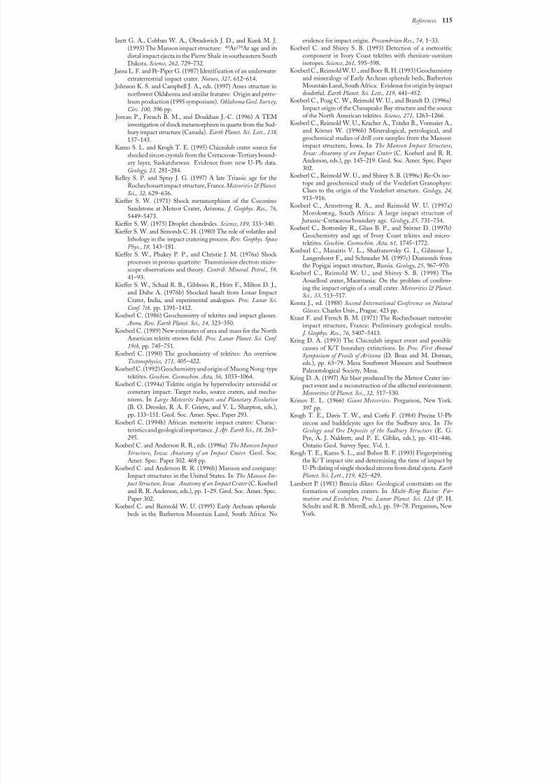
8/8/2019 Traces of Catastrophe - Book
http://slidepdf.com/reader/full/traces-of-catastrophe-book 125/130
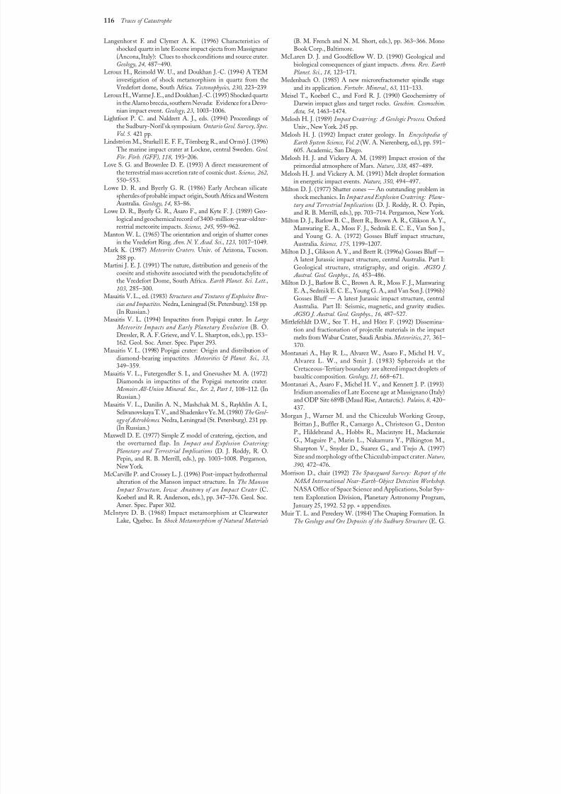
8/8/2019 Traces of Catastrophe - Book
http://slidepdf.com/reader/full/traces-of-catastrophe-book 126/130
116 Traces of Catastrophe
Langenhorst F. and Clymer A. K. (1996) Characteristics of shocked quartz in late Eocene impact ejecta from Massignano(Ancona, Italy): Clues to shock conditions and source crater.Geology, 24, 487–490.
Leroux H., Reimold W. U., and Doukhan J.-C. (1994) A TEMinvestigation of shock metamorphism in quartz from theVredefort dome, South Africa. Tectonophysics, 230, 223–239.
Leroux H., Warme J. E., and Doukhan J.-C. (1995) Shocked quartz in the Alamo breccia, southern Nevada: Evidence for a Devo-nian impact event. Geology, 23, 1003–1006.
Lightfoot P. C. and Naldrett A. J., eds. (1994) Proceedings of the Sudbury-Noril’sk symposium. Ontario Geol. Survey, Spec.Vol. 5. 421 pp.
Lindström M., Sturkell E. F. F., Törnberg R., and Ormö J. (1996) The marine impact crater at Lockne, central Sweden. Geol.För. Förh. (GFF), 118, 193–206.
Love S. G. and Brownlee D. E. (1993) A direct measurement of the terrestrial mass accretion rate of cosmic dust. Science, 262,550–553.
Lowe D. R. and Byerly G. R. (1986) Early Archean silicatespherules of probable impact origin, South Africa and WesternAustralia. Geology, 14, 83–86.
Lowe D. R., Byerly G. R., Asaro F., and Kyte F. J. (1989) Geo-logical and geochemical record of 3400-million-year-old ter-restrial meteorite impacts. Science, 245, 959–962.
Manton W. L. (1965) The orientation and origin of shatter conesin the Vredefort Ring. Ann. N. Y. Acad. Sci., 123, 1017–1049.
Mark K. (1987) Meteorite Craters. Univ. of Arizona, Tucson.288 pp.
Martini J. E. J. (1991) The nature, distribution and genesis of thecoesite and stishovite associated with the pseudotachylite of the Vredefort Dome, South Africa. Earth Planet. Sci. Lett.,103, 285–300.
Masaitis V. L., ed. (1983) Structures and Textures of Explosive Brec-cias and Impactites. Nedra, Leningrad (St. Petersburg). 158pp.(In Russian.)
Masaitis V. L. (1994) Impactites from Popigai crater. In Large Meteorite Impacts and Early Planetary Evolution (B. O.Dressler, R. A. F. Grieve, and V. L. Sharpton, eds.), pp. 153–162. Geol. Soc. Amer. Spec. Paper 293.
Masaitis V. L. (1998) Popigai crater: Origin and distribution of diamond-bearing impactites. Meteoritics & Planet. Sci., 33,349–359.
Masaitis V. L., Futergendler S. I., and Gnevushev M. A. (1972)Diamonds in impactites of the Popigai meteorite crater. Memoirs All-Union Mineral. Soc., Ser. 2, Part 1, 108–112. (InRussian.)
Masaitis V. L., Danilin A. N., Mashchak M. S., Raykhlin A. I.,Selivanovskaya T. V., and Shadenkov Ye. M. (1980) The Geol-ogy of Astroblemes. Nedra, Leningrad (St. Petersburg). 231pp.
(In Russian.)Maxwell D. E. (1977) Simple Z model of cratering, ejection, andthe overturned flap. In Impact and Explosion Cratering:Planetary and Terrestrial Implications (D. J. Roddy, R. O.Pepin, and R. B. Merrill, eds.), pp. 1003–1008. Pergamon,New York.
McCarville P. and Crossey L. J. (1996) Post-impact hydrothermalalteration of the Manson impact structure. In The Manson Impact Structure, Iowa: Anatomy of an Impact Crater (C.Koeberl and R. R. Anderson, eds.), pp. 347–376. Geol. Soc.Amer. Spec. Paper 302.
McIntyre D. B. (1968) Impact metamorphism at ClearwaterLake, Quebec. In Shock Metamorphism of Natural Materials
(B. M. French and N. M. Short, eds.), pp. 363–366. MonoBook Corp., Baltimore.
McLaren D. J. and Goodfellow W. D. (1990) Geological andbiological consequences of giant impacts. Annu. Rev. EarthPlanet. Sci., 18, 123–171.
Medenbach O. (1985) A new microrefractometer spindle stageand its application. Fortschr. Mineral., 63, 111–133.
Meisel T., Koeberl C., and Ford R. J. (1990) Geochemistry of Darwin impact glass and target rocks. Geochim. Cosmochim. Acta, 54, 1463–1474.
Melosh H. J. (1989) Impact Cratering: A Geologic Process. OxfordUniv., New York. 245 pp.
Melosh H. J. (1992) Impact crater geology. In Encyclopedia of Earth System Science, Vol. 2 (W. A. Nierenberg, ed.),pp. 591–605. Academic, San Diego.
Melosh H. J. and Vickery A. M. (1989) Impact erosion of theprimordial atmosphere of Mars. Nature, 338, 487–489.
Melosh H. J. and Vickery A. M. (1991) Melt droplet formationin energetic impact events. Nature, 350, 494–497.
Milton D. J. (1977) Shatter cones — An outstanding problem inshock mechanics. In Impact and Explosion Cratering: Plane-tary and Terrestrial Implications (D. J. Roddy, R. O. Pepin,
and R. B. Merrill, eds.), pp. 703–714. Pergamon, New York.Milton D. J., Barlow B. C., Brett R., Brown A. R., Glikson A. Y.,Manwaring E. A., Moss F. J., Sedmik E. C. E., Van Son J.,and Young G. A. (1972) Gosses Bluff impact structure,Australia. Science, 175, 1199–1207.
Milton D. J., Glikson A. Y., and Brett R. (1996a) Gosses Bluff —A latest Jurassic impact structure, central Australia. PartI:Geological structure, stratigraphy, and origin. AGSO J. Austral. Geol. Geophys., 16, 453–486.
Milton D. J., Barlow B. C., Brown A. R., Moss F. J., ManwaringE. A., Sedmik E. C. E., Young G. A., and Van Son J. (1996b)Gosses Bluff — A latest Jurassic impact structure, centralAustralia. Part II: Seismic, magnetic, and gravity studies. AGSO J. Austral. Geol. Geophys., 16, 487–527.
Mittlefehldt D.W., See T. H., and Hörz F. (1992) Dissemina-tion and fractionation of projectile materials in the impactmelts from Wabar Crater, Saudi Arabia. Meteoritics, 27, 361–370.
Montanari A., Hay R. L., Alvarez W., Asaro F., Michel H. V.,Alvarez L. W., and Smit J. (1983) Spheroids at theCretaceous-Tertiary boundary are altered impact droplets of basaltic composition. Geology, 11, 668–671.
Montanari A., Asaro F., Michel H. V., and Kennett J. P. (1993)Iridium anomalies of Late Eocene age at Massignano (Italy)and ODP Site 689B (Maud Rise, Antarctic). Palaios, 8, 420–437.
Morgan J., Warner M. and the Chicxulub Working Group,Brittan J., Buffler R., Camargo A., Christeson G., Denton
P., Hildebrand A., Hobbs R., Macintyre H., MackenzieG., Maguire P., Marin L., Nakamura Y., Pilkington M.,Sharpton V., Snyder D., Suarez G., and Trejo A. (1997)Size and morphology of the Chicxulub impact crater. Nature,390, 472–476.
Morrison D., chair (1992) The Spaceguard Survey: Report of the NASA International Near-Earth-Object Detection Workshop.NASA Office of Space Science and Applications, Solar Sys-tem Exploration Division, Planetary Astronomy Program,
January 25, 1992. 52 pp. + appendixes.Muir T. L. and Peredery W. (1984) The Onaping Formation. In
The Geology and Ore Deposits of the Sudbury Structure (E. G.
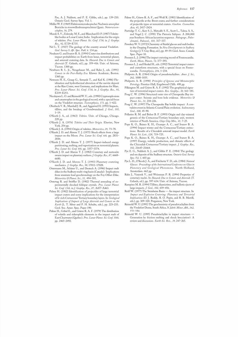
8/8/2019 Traces of Catastrophe - Book
http://slidepdf.com/reader/full/traces-of-catastrophe-book 127/130
References 117
Pye, A. J. Naldrett, and P. E. Giblin, eds.), pp. 139–210.Ontario Geol. Survey Spec. Vol. 1.
Müller W. F. (1969) Elektronmicroskopischer Nachweis amorpherBereiche in stosswellenbeanspruchtem Quarz. Naturwissen-schaften, 56, 279.
Murali A. V., Zolensky M. E., and Blanchard D. P. (1987) Tektite-like bodies at Lonar Crater, India: Implications for the originof tektites. Proc. Lunar Planet. Sci. Conf. 17th, in J. Geophys.Res., 92, E729–E735.
Nel L. T. (1927) The geology of the country around Vredefort.Geol. Survey S. Afr. Spec. Publ. 6. 134 pp.
Neukum G. and Ivanov B. A. (1994) Crater size distributions andimpact probabilities on Earth from lunar, terrestrial-planet,and asteroid cratering data. In Hazards Due to Comets and Asteroids (T. Gehrels, ed.), pp. 359–416. Univ. of Arizona, Tucson. 1300 pp.
Newburn R. L. Jr., Neugebauer M., and Rahe J., eds. (1991)Comets in the Post-Halley Era. Kluwer Academic, Boston.1360 pp.
Newsom H. E., Graup G., Sewards T., and Keil K. (1986) Flu-idization and hydrothermal alteration of the suevite depositat the Ries Crater, west Germany, and implications for Mars.
Proc. Lunar Planet. Sci. Conf. 17th, in J. Geophys. Res., 91,E239–E251.Nicolaysen L. O. and Reimold W. U., eds. (1990) Cryptoexplosions
and catastrophes in the geological record, with a special focuson the Vredefort structure. Tectonophysics, 171, pp. 1–422.
Oberbeck V. R., Marshall J. R., and Aggarwal H. (1993) Impacts,tillites, and the breakup of Gondwanaland. J. Geol., 101,1–19.
O’Keefe J. A., ed. (1963) Tektites. Univ. of Chicago, Chicago.228pp.
O’Keefe J. A. (1976) Tektites and Their Origin. Elsevier, New York. 254 pp.
O’Keefe J. A. (1994) Origin of tektites. Meteoritics, 29, 73–78.O’Keefe J. D. and Ahrens T. J. (1975) Shock effects from a large
impact on the Moon. Proc. Lunar Sci. Conf. 6th, pp. 2831–2844.O’Keefe J. D. and Ahrens T. J. (1977) Impact-induced energy
partitioning, melting, and vaporization on terrestrial planets.Proc. Lunar Sci. Conf. 8th, pp. 3357–3374.
O’Keefe J. D. and Ahrens T. J. (1982) Cometary and meteoriteswarm impact on planetary surfaces. J. Geophys. Res., 87, 6668–6680.
O’Keefe J. D. and Ahrens T. J. (1993) Planetary crateringmechanics. J. Geophys. Res., 98, 17011–17028.
Ostermann M., Schärer U., and Deutsch A. (1996) Impact meltdikes in the Sudbury multi-ring basin (Canada): Implicationsfrom uranium-lead geochronology on the Foy Offset Dike. Meteoritics & Planet. Sci., 31, 494–501.
Ostertag R. and Stöffler D. (1982) Thermal annealing of ex-perimentally shocked feldspar crystals. Proc. Lunar Planet.Sci. Conf. 13th, in J. Geophys. Res., 87, A457–A463.
Palme H. (1982) Identification of projectiles of large terrestrialimpact craters and some implications for the interpretationof Ir-rich Cretaceous/Tertiary boundary layers. In Geological Implications of Impacts of Large Asteroids and Comets on the Earth (L. T. Silver and P. H. Schultz, eds.), pp. 223–233.Geol. Soc. Amer. Spec. Paper 190.
Palme H., Göbel E., and Grieve R. A. F. (1979) The distributionof volatile and siderophile elements in the impact melt of East Clearwater (Quebec). Proc. Lunar Planet. Sci. Conf. 10th,pp. 2465–2492.
Palme H., Grieve R. A. F., and Wolf R. (1981) Identification of the projectile at the Brent crater, and further considerationsof projectile types at terrestrial craters. Geochim. Cosmochim. Acta, 45, 2417–2424.
Partridge T. C., Kerr S. J., Metcalfe S. E., Scott L., Talma A. S.,and Vogel J. C. (1993) The Pretoria Saltpan: A 200,000
year Southern African lacustrine sequence. Paleogeogr., Paleo-climatol., Paleoecol., 101, 317–337.
Peredery W. V. (1972) Chemistry of fluidal glasses and melt bodiesin the Onaping Formation. In New Developments in SudburyGeology ( J. V. Guy-Bray, ed.), pp. 49–59. Geol. Assoc. CanadaSpec. Paper 10.
Pesonen L. J. (1996) The impact cratering record of Fennoscandia. Earth, Moon, Planets, 72, 377–393.
Pesonen L. J. and Henkel H., eds. (1992) Terrestrial impact cratersand craterform structures, with a special focus on Fenno-scandia. Tectonophysics, 216, 1–234.
Philpotts A. R. (1964) Origin of pseudotachylites. Amer. J. Sci., 262, 1008–1035.
Philpotts A. R. (1990) Principles of Igneous and Metamorphic Petrology. Prentice-Hall, Engelwood Cliffs. 498 pp.
Pilkington M. and Grieve R. A. F. (1992) The geophysical signa-
ture of terrestrial impact craters. Rev. Geophys., 30, 161–181.Poag C. W. (1996) Structural outer rim of Chesapeake Bay im-
pact crater: Seismic and bore hole evidence. Meteoritics & Planet. Sci., 31, 218–226.
Poag C. W. (1997) The Chesapeake Bay bolide impact: A con- vulsive event in Atlantic Coastal Plain evolution. SedimentaryGeol., 108, 45–90.
Pollastro R. M. and Bohor B. F. (1993) Origin and clay-mineralgenesis of the Cretaceous/Tertiary boundary unit, westerninterior of North America. Clays Clay Min., 41, 7–25.
Pope K. O., Baines K. H., Ocampo A. C., and Ivanov B. A.(1994) Impact winter and the Cretaceous/Tertiary extinc-tions: Results of a Chicxulub asteroid impact model. EarthPlanet. Sci. Lett., 128, 719–725.
Pope K. O., Baines K. H., Ocampo A. C., and Ivanov B. A.(1997) Energy, volatile production, and climatic effects of the Chicxulub Cretaceous/Tertiary impact. J. Geophys. Res.,102, 21645–21664.
Pye E. G., Naldrett A. J., and Giblin P. E. (1984) The geology and ore deposits of the Sudbury structure. Ontario Geol. SurveySpec. Vol. 1, 603 pp.
Pye L. D., O’Keefe J. A., and Fréchette V. D., eds. (1984) Natural Glasses: Proceedings of the International Conference on Glass inPlanetary and Geological Phenomena. North-Holland,Amsterdam. 662 pp.
Rahe J., Vanysek V., and Weissman P. R. (1994) Properties of cometary nuclei. In Hazards Due to Comets and Asteroids (T.
Gehrels, ed.), pp. 597–634. Univ. of Arizona, Tucson.Rampino M. R. (1994) Tillites, diamictites, and ballistic ejects of large impacts. J. Geol., 102, 439–456.
Reiff W. (1977) The Steinheim Basin — An impact structure. In Impact and Explosion Cratering: Planetary and Terrestrial Implications (D. J. Roddy, R. O. Pepin, and R. B. Merrill,eds.), pp. 309–320. Pergamon, New York.
Reimold W. U. (1991) The geochemistry of pseudotachylites fromthe Vredefort Dome, South Africa. N. Jahrb. Miner. Abh., 162,151–184.
Reimold W. U. (1995) Pseudotachylite in impact structures —Generation by friction melting and shock brecciation?: Areview and discussion. Earth-Sci. Rev., 39, 247–265.
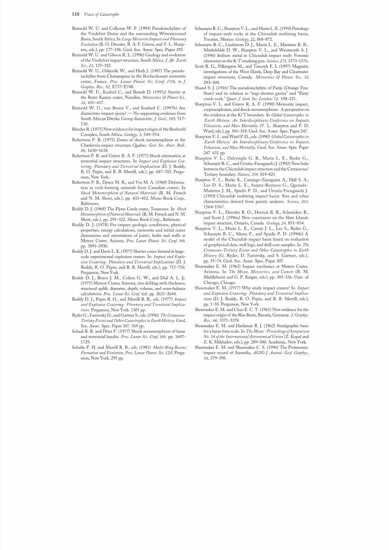
8/8/2019 Traces of Catastrophe - Book
http://slidepdf.com/reader/full/traces-of-catastrophe-book 128/130
118 Traces of Catastrophe
Reimold W. U. and Colliston W. P. (1994) Pseudotachylites of the Vredefort Dome and the surrounding WitwatersrandBasin, South Africa. In Large Meteorite Impacts and Planetary Evolution (B. O. Dressler, R. A. F. Grieve, and V. L. Sharp-ton, eds.), pp. 177–196. Geol. Soc. Amer. Spec. Paper 293.
Reimold W. U. and Gibson R. L. (1996) Geology and evolutionof the Vredefort impact structure, South Africa. J. Afr. EarthSci., 23, 125–182.
Reimold W. U., Oskierski W., and Huth J. (1987) The pseudo-tachylite from Champagnac in the Rochechouart meteoritecrater, France. Proc. Lunar Planet. Sci. Conf. 17th, in J.Geophys. Res., 92, E737–E748.
Reimold W. U., Koeberl C., and Brandt D. (1997a) Suevite atthe Roter Kamm crater, Namibia. Meteoritics & Planet Sci.,32, 431–437.
Reimold W. U., von Brunn V., and Koeberl C. (1997b) Arediamictites impact ejecta? — No supporting evidence fromSouth African Dwyka Group diamictite. J. Geol., 105, 517–530.
Rhodes R. (1975) New evidence for impact origin of the BushveldComplex, South Africa. Geology, 3, 549–554.
Robertson P. B. (1975) Zones of shock metamorphism at theCharlevoix impact structure, Quebec. Geol. Soc. Amer. Bull.,86, 1630–1638.
Robertson P. B. and Grieve R. A. F. (1977) Shock attenuation atterrestrial impact structures. In Impact and Explosion Cra-tering: Planetary and Terrestrial Implications (D. J. Roddy,R. O. Pepin, and R. B. Merrill, eds.), pp. 687–702. Perga-mon, New York.
Robertson P. B., Dence M. R., and Vos M. A. (1968) Deforma-tion in rock-forming minerals from Canadian craters. InShock Metamorphism of Natural Materials (B. M. Frenchand N. M. Short, eds.), pp. 433–452. Mono Book Corp.,Baltimore.
Roddy D. J. (1968) The Flynn Creek crater, Tennessee. In Shock Metamorphism of Natural Materials (B. M. French and N. M.Short, eds.), pp. 291–322. Mono Book Corp., Baltimore.
Roddy D. J. (1978) Pre-impact geologic conditions, physicalproperties, energy calculations, meteorite and initial craterdimensions and orientations of joints, faults and walls atMeteor Crater, Arizona. Proc. Lunar Planet. Sci. Conf. 9th,pp. 3891–3930.
Roddy D. J. and Davis L. K. (1977) Shatter cones formed in large-scale experimental explosion craters. In Impact and Explo-sion Cratering: Planetary and Terrestrial Implications (D. J.Roddy, R. O. Pepin, and R. B. Merrill, eds.), pp. 715–750.Pergamon, New York.
Roddy D. J., Boyce J. M., Colton G. W., and Dial A. L. Jr.(1975) Meteor Crater, Arizona, rim dril ling with thickness,structural uplift, diameter, depth, volume, and mass-balancecalculations. Proc. Lunar Sci. Conf. 6th, pp. 2621–2644.
Roddy D. J., Pepin R. O., and Merrill R. B., eds. (1977) Impact and Explosion Cratering: Planetary and Terrestrial Implica-tions. Pergamon, New York. 1301 pp.
Ryder G., Fastovsky D., and Gartner S., eds. (1996) The Cretaceous-Tertiary Event and Other Catastrophes in Earth History. Geol.Soc. Amer. Spec. Paper 307. 569 pp.
Schaal R. B. and Hörz F. (1977) Shock metamorphism of lunarand terrestrial basalts. Proc. Lunar Sci. Conf. 8th, pp. 1697–1729.
Schultz P. H. and Merrill R. B., eds. (1981) Multi-RingBasins:Formation and Evolution, Proc. Lunar Planet. Sci. 12A . Perga-mon, New York. 295 pp.
Schuraytz B. C., Sharpton V. L., and Marín L. E. (1994) Petrology of impact-melt rocks at the Chicxulub multiring basin,
Yucatán, Mexico. Geology, 22, 868–872.Schuraytz B. C., Lindstrom D. J., Marín L. E., Martinez R. R.,
Mittlefehldt D. W., Sharpton V. L., and Wentworth S. J.(1996) Iridium metal in Chicxulub impact melt: Forensicchemistry on the K-T smoking gun. Science, 271, 1573–1576.
Scott R. G., Pilkington M., and Tanczyk E. I. (1997) Magneticinvestigations of the West Hawk, Deep Bay and Clearwaterimpact structures, Canada. Meteoritics & Planet. Sci., 32,293–308.
Shand S. J. (1916) The pseudotachylyte of Parijs (Orange FreeState) and its relation to “trap-shotten gneiss” and “flinty crush-rock.” Quart. J. Geol. Soc. London, 72, 198–221.
Sharpton V. L. and Grieve R. A. F. (1990) Meteorite impact,cryptoexplosion, and shock metamorphism: A perspective onthe evidence at the K/ T boundary. In Global Catastrophes in Earth History: An Interdisciplinary Conference on Impacts,Volcanism, and Mass Mortality (V. L. Sharpton and P. D.
Ward, eds.), pp. 301–318. Geol. Soc. Amer. Spec. Paper 247.Sharpton V. L. and Ward P. D., eds. (1990) Global Catastrophes in
Earth History: An Interdisciplinary Conference on Impacts,
Volcanism, and Mass Mortality. Geol. Soc. Amer. Spec. Paper247. 631 pp.Sharpton V. L., Dalrymple G. B., Marín L. E., Ryder G.,
Schuraytz B. C., and Urrutia-Fucugauchi J. (1992) New linksbetween the Chicxulub impact structure and the Cretaceous/
Tertiary boundary. Nature, 359, 819–821.Sharpton V. L., Burke K., Camargo-Zanoguera A., Hall S. A.,
Lee D. S., Marín L. E., Suárez-Reynoso G., Quezada-Muñeton J. M., Spudis P. D., and Urrutia-Fucugauchi J.(1993) Chicxulub multiring impact basin: Size and othercharacteristics derived from gravity analyses. Science, 261,1564–1567.
Sharpton V. L., Dressler B. O., Herrick R. R., Schneiders B.,and Scott J. (1996a) New constraints on the Slate Islands
impact structure, Ontario, Canada. Geology, 24, 851–854.Sharpton V. L., Marín L. E., Carney J. L., Lee S., Ryder G.,
Schuraytz B. C., Sikora P., and Spudis P. D. (1996b) Amodel of the Chicxulub impact basin based on evaluationof geophysical data, well logs, and drill core samples. In The Cretaceous-Tertiary Event and Other Catastrophes in EarthHistory (G. Ryder, D. Fastovsky, and S. Gartner, eds.),pp. 55–74. Geol. Soc. Amer. Spec. Paper 307.
Shoemaker E. M. (1963) Impact mechanics at Meteor Crater,Arizona. In The Moon, Meteorites, and Comets (B. M.Middlehurst and G. P. Kuiper, eds.), pp. 301–336. Univ. of Chicago, Chicago.
Shoemaker E. M. (1977) Why study impact craters? In Impact and Explosion Cratering: Planetary and Terrestrial Implica-
tions (D. J. Roddy, R. O. Pepin, and R. B. Merrill, eds.),pp. 1–10. Pergamon, New York.
Shoemaker E. M. and Chao E. C. T. (1961) New evidence for theimpact origin of the Ries Basin, Bavaria, Germany. J. Geophys.Res., 66, 3371–3378.
Shoemaker E. M. and Hackman R. J. (1962) Stratigraphic basisfor a lunar time scale. In The Moon: Proceedings of Symposium No. 14 of the International Astronomical Union (Z. Kopal andZ. K. Mikhailov, eds.), pp. 289–300. Academic, New York.
Shoemaker E. M. and Shoemaker C. S. (1996) The Proterozoicimpact record of Australia. AGSO J. Austral. Geol. Geophys.,16, 379–398.
8/8/2019 Traces of Catastrophe - Book
http://slidepdf.com/reader/full/traces-of-catastrophe-book 129/130
References 119
Shoemaker E. M., Hackman R. J., and Eggleton R. E. (1963)Interplanetary correlation of geologic time. Adv. Astronaut.Sci., 8, 70–89.
Sibson R. H. (1975) Generation of pseudotachylyte by ancientseismic faulting. Geophys. J. Roy. Astron. Soc., 43, 775–794.
Sigurdsson H., D’Hondt S., Arthur M. A., Bralower T. J.,Zachos J. C., van Fossen M., and Channell J. E. T. (1991a)Glass from the Cretaceous/Tertiary boundary in Haiti. Nature,
349,482–487.
Sigurdsson H., Bonté Ph., Turpin L., Chaussidon M., MetrichN., Steinberg M., Pradel Ph., and D’Hondt S. (1991b) Geo-chemical constraints on source region of Cretaceous/Tertiary impact glasses. Nature, 353, 839–842.
Silver L. T. and Schultz P. H., eds. (1982) Geological Implicationsof Impacts of Large Asteroids and Comets on the Earth. Geol.Soc. Amer. Spec. Paper 190. 528 pp.
Simonds C. H., Warner J. L., Phinney W. C., and McGee P. E.(1976) Thermal model for impact breccia lithification: Mani-couagan and the Moon. Proc. Lunar Sci. Conf. 7th, pp. 2509–2528.
Simonds C. H., Floran R. J., McGee P. E., Phinney W. C., and Warner J. L. (1978a) Petrogenesis of melt rocks, Manicou-
agan impact structure, Quebec. J. Geophys. Res., 83, 2773–2788.Simonds C. H., Phinney W. C., McGee P. E., and Cochran A.
(1978b) West Clearwater, Quebec, impact structure, PartI:Field geology, structure and bulk chemistry.Proc. Lunar Planet.Sci. Conf. 9th, pp. 2633–2658.
Simonson B. M. (1992) Geological evidence for a strewn field of impact spherules in the early Precambrian Hamersley Basinof Western Australia. Geol. Soc. Amer. Bull., 104, 829–839.
Simonson B. M. and Davies D. (1996) PGEs and quartz grains ina resedimented Late Archean impact horizon in the Ham-ersley Group of Western Australia (abstract). In Lunar and Planetary Science XXVII, pp. 1203–1204. Lunar and Planetary Institute, Houston.
Simonson B. M., Beukes N. J., and Hassler S. (1997) Discovery of a Neoarchean impact spherule horizon in the TransvaalSupergroup of South Africa and possible correlations to theHamersley Basin of Western Australia (abstract). In Lunar and Planetary Science XXVIII, pp. 1323–1324. Lunar andPlanetary Institute, Houston.
Speers E. C. (1957) The age relation and origin of common Sud-bury breccia. J. Geol., 65, 497–514.
Spencer J. R. and Mitton J., eds. (1995) The Great Comet Crash:The Impact of Comet Shoemaker-Levy 9 on Jupiter.CambridgeUniv., New York. 118 pp.
Spray J. G. (1995) Pseudotachylyte controversy: Fact or friction?Geology, 23, 1119–1122.
Spray J. G. (1997) Superfaults. Geology, 25, 579–582.
Spray J. G. and Thompson L. M. (1995) Friction melt distributionin multi-ring impact basins. Nature, 373, 130–132.
Spray J. G., Kelley S. P., and Reimold W. U. (1995) Laser probeargon-40/argon-39 dating of coesite- and stishovite-bearingpseudotachylites and the age of the Vredefort impact event. Meteoritics, 30, 335–343.
Spudis P. D. (1993) The Geology of Multi-Ring Impact Basins:The Moon and Other Planets. Cambridge Univ., New York.263 pp.
Stähle V. (1973) Cordierite glass formed by shock in a cordierite-garnet-gneiss from the Ries crater, Germany. Earth Planet.Sci. Lett., 18, 385–390.
Stepto D. (1990) The geology and gravity field in the central coreof the Vredefort structure. Tectonophysics, 171, 75–103.
Stöffler D. (1966) Zones of impact metamorphism in the crystallinerocks at the Nördlinger Ries Crater. Contrib. Mineral. Petrol.,12, 15–24.
Stöffler D. (1967) Deformation und Umwandlung von Plagioklasdurch Stosswellen in den Gesteinen der Nördlinger Ries.Contrib. Mineral. Petrol., 16, 51–83.
Stöffler D. (1971) Progressive metamorphism and classificationof shocked and brecciated crystalline rocks at impact craters. J. Geophys. Res., 76, 5541–5551.
Stöffler D. (1972) Deformation and transformation of rock-forming minerals by natural and experimental shock proc-esses: I. Behavior of minerals under shock compression.Fortschr. Mineral., 49, 50–113.
Stöffler D. (1974) Deformation and transformation of rock-forming minerals by natural and experimental shock proc-esses: II. Physical properties of shocked minerals. Fortschr. Mineral., 51, 256–289.
Stöffler D. (1984) Glasses formed by hypervelocity impact. J. Non-Crystall. Solids, 67, 465–502.
Stöffler D. and Grieve R. A. F. (1994) Classification andnomenclature of impact metamorphic rocks: A proposal tothe IUGS Subcommission on the Systematics of Meta-morphic Rocks (abstract). In European Sci. Foundation Second Intl. Workshop on “Impact Cratering and the Evolution of Planet Earth”: The Identification and Characterization of Impacts,Ostersund, Sweden.
Stöffler D. and Grieve R. A. F. (1996) IUGS classification andnomenclature of impact metamorphic rocks: Towards a finalproposal (abstract). In Intl. Workshop, Postojna 96: The Role of Impact Processes in the Geological and Biological Evolution of Planet Earth (K. Drobne, S. Gorican, and B. Kotnik, eds.),pp. 89–90. Ljubljana.
Stöffler D. and Langenhorst F. (1994) Shock metamorphism of quartz in nature and experiment: I. Basic observation andtheory. Meteoritics, 29, 155–181.
Stöffler D., Knöll H.-D., and Maerz U. (1979) Terrestrial andlunar impact breccias and the classification of lunar highlandrocks. Proc. Lunar Planet. Sci. Conf. 10th, pp. 639–675.
Stöffler D., Bischoff L., Oskierski W., and Wiest B. (1988)Structural deformation, breccia formation, and shock meta-morphism in the basement of complex terrestrial impactcraters: implications for the cratering process. In Deep Drill-ing in Crystalline Bedrock, Vol. 1: The Deep Gas Drilling in the Siljan Impact Structure, Sweden and Astroblemes (A. Bodénand K. G. Eriksson, eds.), pp. 277–297. Springer-Verlag,New York.
Stöffler D., Deutsch A., Avermann M., Bischoff L., BrockmeyerP., Buhl D., Lakomy R., and Müller-Mohr V. (1994) Theformation of the Sudbury structure, Canada: Toward a unified
impact model. In Large Meteorite Impacts and Planetary Evolu-tion (B. O. Dressler, R. A. F. Grieve, and V. L. Sharpton,eds.), pp. 303–318. Geol. Soc. Amer. Spec. Paper 293.
Storzer D. and Koeberl C. (1991) Uranium and zirconiumenrichments in Libyan Desert Glass: Zircon, baddeleyite andhigh temperature history of the glass (abstract). In Lunar and Planetary Science XXII, pp. 1345–1346. Lunar and Planetary Institute, Houston.
Symes S. J. K., Sears D. W. G., Akridge D. G., Huang S., andBenoit P. H. (1998) The crystalline lunar spherules: Theirformation and implications for the origin of meteoritic chon-drules. Meteoritics & Planet. Sci., 33, 13–29.

8/8/2019 Traces of Catastrophe - Book
http://slidepdf.com/reader/full/traces-of-catastrophe-book 130/130
120 Traces of Catastrophe
Taylor G. J., Warren P., Ryder G., Delano J., Pieters C., andLofgren G. (1991) Lunar rocks. In Lunar Sourcebook: A User’s Guide to the Moon (G. H. Heiken, D. T. Vaniman,and B. M. French, eds.), pp. 183–284. Cambridge Univ., New
York. Taylor S. R. (1975) Lunar Science: A Post-Apollo View. Pergamon,
New York. 372 pp. Taylor S. R. (1982) Planetary Science: A Lunar Perspective. Lunar
and Planetary Institute, Houston. 481 pp. Taylor S. R. (1992) Solar System Evolution: A New Perspective.
Cambridge Univ., New York. 307 pp. Taylor S. R. and Koeberl C. (1994) The origin of tektites: Com-
ment on a paper by J. A. O’Keefe. Meteoritics, 29, 739–742. Therriault A. M. and Lindström M. (1995) Planar deformation
features in quartz grains from the resurge deposit of theLockne structure, Sweden. Meteoritics, 30, 700–703.
Therriault A. M., Reimold W. U., and Reid A. M. (1996) Fieldrelations and petrography of the Vredefort Granophyre. S. Afr. J. Geol., 99, 1–21.
Therriault A. M., Grieve R. A. F., and Reimold W. U. (1997)Original size of the Vredefort Structure: Implications for thegeological evolution of the Witwatersrand Basin. Meteoritics
& Planet. Sci., 32, 71–77. Thompson L. M. and Spray J. G. (1994) Pseudotachylitic rock distribution and genesis within the Sudbury impact struc-ture. In Large Meteorite Impacts and Planetary Evolution(B. O. Dressler, R. A. F. Grieve, and V. L. Sharpton, eds.),pp. 275–287. Geol. Soc. Amer. Spec. Paper 293.
Trefil J. S. and Raup D. M. (1990) Crater taphonomy andbombardment rates in the Phanerozoic. J. Geol., 98, 385–398.
Turtle E. P. and Pierazzo E. (1998) Constraints on the size of the Vredefort impact crater from numerical modeling. Meteoritics & Planet. Sci., 33, 483–490.
Verschuur G. L. (1996) Impact! The Threat of Comets and Aster-oids. Oxford Univ., New York. 237 pp.
von Engelhardt W. (1990) Distribution, petrography and shock
metamorphism of the ejecta of the Ries crater in Germany—A review. Tectonophysics, 171, 259–273.E lh d W (1997) S i b i f h Ri i
von Engelhardt W. and Stöffler D. (1965) Spaltflächen im Quarz als Anzeichen für Einschläge grosser Meteoriten. Natur-wissenschaften, 17, 489–490.
von Engelhardt W. and Stöffler D. (1968) Stages of shock meta-morphism in crystalline rocks of the Ries Basin, Germany.In Shock Metamorphism of Natural Materials (B. M. Frenchand N. M. Short, eds.), pp. 159–168. Mono BookCorp.,Baltimore.
von Engelhardt W., Stöffler D., and Schneider W. (1969)Petrologische Untersuchungen im Ries. Geol. Bavar., 61,229–295.
von Engelhardt W., Luft E., Arndt J., Schock H., and Weiskirchner W. (1987) Origin of moldavites. Geochim. Cosmochim. Acta.,51, 1425–1443.
Weaver K. F. (1986) Meteorites: Invaders from space. National Geographic, 170, No. 3 (September 1986), pp. 390–418.
Weeks R. A., Underwood J. R. Jr., and Giegengack R. (1984)Libyan Desert Glass: A review. J. Non-Crystall. Solids, 67,593–619.
Weiblen P. W. and Schulz K. J. (1978) Is there any record of meteorite impact in the Archean rocks of North America?Proc. Lunar Planet. Sci. Conf. 9th, pp. 2749–2771.
Wilhelms D. E. (1993) To a Rocky Moon: A Geologist’s History of Lunar Exploration. Univ. of Arizona, Tucson. 477 pp. Wilhelms D. E., McCauley J. F., and Trask N. J. (1987) The
geologic history of the Moon. U.S. Geol. Survey Prof. Paper 1348. 302 pp.
Wilkening L. L., ed. (1982) Comets. Univ. of Arizona, Tucson.766 pp.
Williams G. E. (1986) The Acraman impact structure: Source of ejecta in Late Precambrian shales, South Australia. Science, 233, 200–203.
Wilshire H. G., Offield T. W., Howard K. A., and CummingsD. (1972) Geology of the Sierra Madera cryptoexplosionstructure, Pecos County, Texas. U.S. Geol. Survey Prof. Paper 599-H. 42 pp.
Wood C. R. and Spray J. G. (1998) Origin and emplacement of offset dykes in the Sudbury impact structure: Constraintsf H M i i & Pl S i 33 337 347