tracerco news v1 e3 1q 07 · tordis ssbi delivered to statoil by fmc technologies figure 2 –...
TRANSCRIPT

Over the past 50 years Tracerco hasworked closely with customers to developa range of non-intrusive measurementsolutions for process diagnostics and con-tinuous control worldwide. One suchinstrument that has been installed in asignificant number of global assets isThe TRACERCO Profiler™ that is used intopside projects to optimize separatorcontrol, shutdown and monitoring appli-cations. Using knowledge gained in thedesign of The TRACERCO Profiler™
instrument Tracerco has worked in
partnership with FMC Technologies todesign and successfully test an innovativesolution for separator process control subsea resulting in The TRACERCOProfiler™ for use subsea (Figure 1).
During the early design stages, onemain concern was that critical level con-trol and shutdown measurement systemsneeded to be retrievable. Dual steelwalls, one for the process and one for theinstrument was determined to be the solu-tion for this design challenge. Tracerco’sR&D Team combined the standard top-side profiler design with traditional“through-vessel” radiation technologyand replaced the isotope type used in thetopside version with one containing morepenetrating ability. The selected isotope source size and energy easily penetrates the thick steel walls andprocess medium, providing an instrumentthat is sensitive to small density variations within the process.
The detector arrays are designed to beretrievable so they can be changed in theunlikely event that a fault should occur.The radioactive source arrays have no
A New Dimension to Process Mapping of SubseaSeparator Vessels with The TRACERCO Profiler™By Magne K. Husebø, General Manager, Tracerco Norge ASCo-authors: Dr. Paul Featonby, Tracerco UK and Ola Jemtland, FMC Technologies
NewsVolume 1 Edition 1 Providing Insight Onsite
tracerco�tracerco.com www.tracerco.com 1
INSIDE THIS ISSUE…Process Mapping of Subsea SeparatorVessels .........................................................1
Reservior Near-Wellbore Tracer Studies .......3
Detect Water Ingress of Jacket Members.....6
Figure 1 – Illustration of The TRACERCOProfiler™ system set-up provided courtesyof FMC Technologies
Tordis SSBI delivered to Statoil by FMC Technologies
Figure 2 – Illustration provided by FMCTechnologies of the detector array systemplacement in the subsea separator.
Continued on page 2

moving parts or electronicsand therefore there is no needfor the option of retrievabilityon this part of the instrument.Figure 2 on page 1, providedby FMC Technologies,demonstrates how the designof the retrievable detectorarray system is safely placedinto a dip pipe from top of thesubsea separator.
How The TRACERCO Profiler™Works
The TRACERCO Profiler™
consists of two (or three) parallel pressure sealed pipesinstalled vertically through atop-mounted separator nozzle(Figure 3). One (or two)pipe(s) form the detector dip-pipe(s), including smallgamma detector segmentsstacked vertically in the pipe.The parallel mounted pipecontains tiny encapsulatedgamma-ray sources.
Each source is collimated;the narrow angled radiationbeam traveling horizontallythrough a segment of theprocess fluid and being pickedup by the correspondingdetector in the detector pipe.
The radiation signal receivedat each detector relates to theaverage process density acrossthe distance between sourceand detector, at the height ofwhich the detector is located.Density values of all detectorspresent are presented in a bardiagram representing the density profile of the processfluids. (Figure 4).
Significant change in density represents the level ofinterface between processmedium phases:
• Gas/foam interface• Foam/oil interface • Oil/water interface (top of
oil continuous emulsionlevel),
• Water/oil interface (bottomof water continuous emul-sion band)
• Water/sand interface Detectors are used for
radiation detection. A micro-processor on top of the detector dip-pipe collects datafrom each detector (rawcounts) and transfers data to asignal processor unit locatedin safe area.
As well as providing density information, TheTRACERCO Profiler™ soft-ware calculates the verticallevel position for all separator
process medium interfaces.This level information can beexported to a process controlor shutdown system, asrequired. A SIL2 certified ver-sion of the Profiler coverssafety integrity requirementsfor new process installations.
Separator Process MappingThe TRACERCO Profiler™
can be used in a number ofdifferent process monitoringapplications by looking atchanges in the process densityprofile. Combination of wells,production rate, change inchemical injection and sandjetting are a few examples ofthe different process monitor-ing applications.
The TRACERCO Profiler™
is also widely used for optimization of chemicalinjection of anti-foaming andde-emulsifiers chemicals:foam height and emulsionbandwidth trends logged during trials on differentchemical products provide theinformation needed to reducewaste and improve processes.
System TestingThe subsea profiler has
been qualified to ISO13628with thorough qualificationtests and environmental stressscreening.
During factory acceptancetesting for subsea profilers for
tracerco�tracerco.com www.tracerco.com
Subsea Separator(Continued from page 1)
Figure 4 – Bar Diagram representing the density profile of the process fluids.
................. ı 2
Figure 3 – Illustration of The TRACERCO Profiler™ source and detector configuration.
“The benefits of the
proven TRACERCO
Profiler™ technology
have now been taken
subsea to provide the
ultimate marriage
between performance,
reliability and the
environment.”
Continued on page 5
................. ı 3tracerco�tracerco.com www.tracerco.com
Reservoir Near-Wellbore Tracer Studies Provide EnhancedInformation on Oil Recovery to Deliver Optimal ProductionBy Paul Hewitt, Vice President Americas – Pasadena, Texas USA
Tracerco has developed atracer application that whenapplied in wells allows an oil-field operator to obtain oil flowverification from the wellboreduring clean up and first oilproduction. This technologyprovides oil and gas companiesthe capability of confirmingzonal flow within a well.
In order to extract hydrocar-bon reserves a number of wellsneed to be drilled to transportfluids from an oil reservoir tothe surface. The wells aredrilled to produce an openhole. In a number of cases,steel tubing is lowered into thehole and cemented in place. In other well completionarrangements, a steel screen ispositioned within productivezones that allows oil flow butprevents sand from flowinginto the wellbore. As drillingactivities are costly, wells aredesigned and drilled at deviatedangles. This can vary from vertical and in many cases, isbranched to pass through several zones containinghydrocarbons in order to maxi-mize use of a common borehole to the surface. In a numberof cases, drilling is carried outvertically and then horizontallyfor many kilometers within anoil bearing strata, allowing previously uneconomicalreserves to be extracted. Once awellbore has been drilled andproduction started it is crucialto ascertain oil and gas flowrate from the well but also con-firm the origination of oil fromthe various production zones.
Principles of the TechniqueThe principle of the technol-
ogy involves the positioning ofa number of different tracermaterials onto screens, pupjoints, or perforation guns to be
run to specific positions alongthe length of the wellbore aspart of the production string orcompletion process. Oncelocated at known positions thetracers remain in place untilhydrocarbon flow passes theirlocation. When this occurs thetracer material is carried withthe hydrocarbon to the surface.Production sampling duringclean up and first oil flow, fol-lowed by analysis for presenceof tracer materials within theproduction fluid allows flowzones to be measured that contribute to overall produc-tion. Stable tracers are requiredat reservoir conditions for significant periods of time, sensitive to analysis and usedin a suitable chemical form that ensures solubility in crudeoil while remaining insolublein water.
Positioning Tracer MaterialsWithin The Wellbore
Two methods are used toposition specific tracer materi-als within the completion stringdependent upon completiondesign.
In the case of screen comple-tions the tracer is added to anoil soluble wax and then eithercoated to the inside of a pupjoint that is used within thecompletion string or applieddirectly to an outer screen section. The wax is allowed tocure over a 24 hour time periodprior to running into the hole.The wax may be applied eitherat the work site or prior to dis-patch of the screens/pup jointsfrom a manufacturers facility.
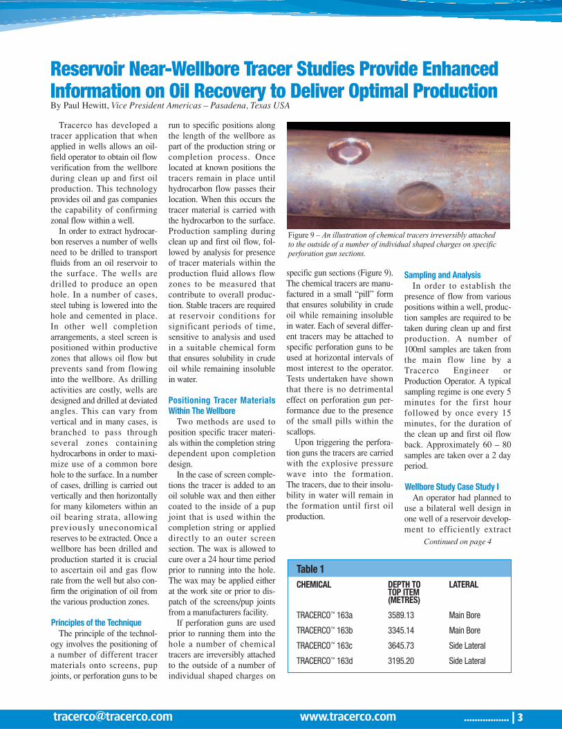
If perforation guns are usedprior to running them into thehole a number of chemicaltracers are irreversibly attachedto the outside of a number ofindividual shaped charges on
specific gun sections (Figure 9).The chemical tracers are manu-factured in a small “pill” formthat ensures solubility in crudeoil while remaining insolublein water. Each of several differ-ent tracers may be attached tospecific perforation guns to beused at horizontal intervals ofmost interest to the operator.Tests undertaken have shownthat there is no detrimentaleffect on perforation gun per-formance due to the presenceof the small pills within thescallops.
Upon triggering the perfora-tion guns the tracers are carriedwith the explosive pressurewave into the formation. The tracers, due to their insolu-bility in water will remain inthe formation until first oil production.
Sampling and AnalysisIn order to establish the
presence of flow from variouspositions within a well, produc-tion samples are required to betaken during clean up and firstproduction. A number of100ml samples are taken fromthe main flow line by aTracerco Engineer orProduction Operator. A typicalsampling regime is one every 5minutes for the first hour followed by once every 15minutes, for the duration of the clean up and first oil flowback. Approximately 60 – 80samples are taken over a 2 dayperiod.
Wellbore Study Case Study IAn operator had planned to
use a bilateral well design inone well of a reservoir develop-ment to efficiently extract
Continued on page 4
Table 1 CHEMICAL DEPTH TO LATERAL
TOP ITEM(METRES)
TRACERCO™ 163a 3589.13 Main Bore
TRACERCO™ 163b 3345.14 Main Bore
TRACERCO™ 163c 3645.73 Side Lateral
TRACERCO™ 163d 3195.20 Side Lateral
Figure 9 – An illustration of chemical tracers irreversibly attachedto the outside of a number of individual shaped charges on specificperforation gun sections.

................. ı 4tracerco�tracerco.com www.tracerco.com
hydrocarbons from two inde-pendent reservoir pay zones.They wished to verify that bothzones were contributing to overalloil production and that oil wasflowing from the toe and centrepositions of each lateral.
Four unique chemical tracermaterials were applied to theouter surface of individual screensections to be used within thecompletion at a shore base priorto shipment offshore. The com-pletion design used the samesized screens in both the mainbore and lateral. The screens wererun in hole by the operator duringthe positioning of the completionarrangement. The position of trac-er materials is shown in Table 1on page 3.
Samples were taken at regularintervals by Tracerco engineersduring clean up to the drilling rigand then during first flow fromthe well back to the main floatingproduction facility through a com-mon subsea line. Results are illus-trated in Figure 10.
The results showed:• Upon first oil flow tracer was
first detected from the mainbore lateral at position 3345.14metres
• 45 minutes later oil fromposition 3589.13 metres withinthe main bore was established.
• During initial clean-up to therig, zero oil flow was detectedfrom the other lateral.
• Upon tie back to the process
system zero tracer wasdetected in the first sample dueto displacement of existing oilfrom other wells present in thesubsea flow-line.
• Further confirmation of flowfrom the main bore upon tieback to the process system.
• Presence of oil flowing fromposition 3195.2 metres in theother lateral was detected.
• Presence of oil flowing fromposition 3645.73 metres in theother lateral was detected some30 minutes after position3195.2 metres.
• Over time all four positionstagged with tracer showed oilflow.
Wellbore Case Study IIA leading oil and gas produc-
tion company contactedTracerco to conduct a TRACERCO Diagnostics™
Wellbore study in order to deter-mine the flow profile of a sidetrack horizontal well. After discussions with the customer,suitable tracers for the applica-tion were determined and twochemical tracers TRACERCO™
162a and TRACERCO™ 163awere selected. The quantity oftracer for the project was calcu-lated using information onexpected oil production flowrate and duration of the clean up
and flow back production test.The two selected chemical
tracers were transferred into asuitable solvent and added to awax at the customer onshorestorage facility. Once mixed thematerial was applied to the innersurface of the pup joints andlabeled. (Figure 11)
The joints were slowly rotated during application to
spread tracer throughout theinner wall. The wax wasallowed to cure. The pup jointswere dispatched to the offshoredrill site and added at specificlocations to the wellbore com-pletion string by the customer.The TRACERCO™ 162a tracerwas located at 150 feet from the toe of the well and theTRACERCO™ 163a tracer posi-tioned half way between the toeand heel.
When the clean up and firstoil flow back was scheduled twoTracerco engineers were mobi-lized. A number of 100ml oilsamples were collected over the
production test time interval.Analysis was carried out. Theresults of the analysis are shownin Figure 12.
The results show that bothtracers were detected with twoseparate and clearly distincttracer concentration versus timecurves with the first tracer(163a) returning within 20 min-utes of production start-up and
Figure 12 – Results indicated that both tracers were detected with two separate and clearly distincttracer concentrations.
1600.0
1400.0
1200.0
1000.0
800.0
600.0
400.0
200.0
0.00 100 200 300 400 500 600
163a 162a
Time (mins)
Co
ncen
trat
ion
(pp
b)
Figure 10 – Results of the four unique chemical tracer materials areillustrated in a graph. Upon first oil flow tracer was first detected fromthe main bore lateral.
Figure 11 – Two selected chemical tracers were transferred into a suitablesolvent and applied to the inner surface of the pup joints and labeled.
1.00
1.00
1.00
1.00
1.00
1.001.00 1.00 1.00 1.00 1.00 1.00 1.00 1.00 1.00 1.00 1.00 1.00 1.00 1.00 1.00
163c 163b163d 163a
Time
No
rmal
ized
Co
unts
Continued on back page
Wellbore(Continued from page 3)
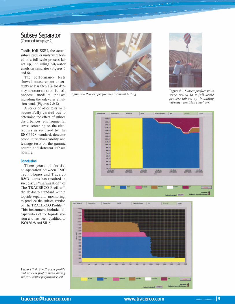
Tordis IOR SSBI, the actualsubsea profiler units were test-ed in a full-scale process labset up, including oil/wateremulsion simulator (Figures 5and 6).
The performance testsshowed measurement uncer-tainty at less then 1% for den-sity measurements, for allprocess medium phasesincluding the oil/water emul-sion band. (Figures 7 & 8)
A series of other tests weresuccessfully carried out todetermine the effect of subseadisturbances, environmentalstress screening on the elec-tronics as required by theISO13628 standard, detectorprobe inter-changeability andleakage tests on the gammasource and detector subseahousing.
ConclusionThree years of fruitful
co-operation between FMCTechnologies and TracercoR&D teams has resulted insuccessful “marinization” ofThe TRACERCO Profiler™,the de-facto standard withintopside separator monitoring,to produce the subsea versionof The TRACERCO Profiler™.This instrument includes allcapabilities of the topside ver-sion and has been qualified toISO13628 and SIL2.
Subsea Separator(Continued from page 2)
................. ı 5tracerco�tracerco.com www.tracerco.com
Figure 6 – Subsea profiler unitswere tested in a full-scaleprocess lab set up, includingoil/water emulsion simulator.
Figures 7 & 8 – Process profileand process profile trend duringsubsea Profiler performance test.
Figure 5 – Process profile measurement testing

North American Headquarters:4106 New West DrivePasadena, TX 77507 USATel: 281 291 7769Fax: 281 291 7709Toll Free: 800 288 8970
Field Office Locations:Corpus Christi, TX 78408 USATel: 361 888 8233
Newark, DE 19702 USATel: 302 454 1109Merrillville, IN 46410 USATel: 219 945 0400Baton Rouge, LA 70820 USATel: 225 761 0621Concord, CA 94520 USATel: 925 687 0900Paramount, CA 90723 USATel: 562 633 8800
Salt Lake City, UT 84119 USATel: 801 478 0736Edmonton, AB, T6E 6A6 CANADATel: 780 469 0055Sarnia, ON, N7S 5G5 CANADATel: 519 332 6160Rio de Janerio, RJ, Brasil, CEP 21040-232Tel: +55 21 3865 0098
www.tracerco.com tracerco�tracerco.com
XM0345/0/0
the second tracer (162a) peakingat 120 minutes. The data confirmsthat both positions within thewellbore were contributing tooverall oil production. The timegap between tracers shows thatboth zones were contributing tooverall production flow ratherthan all flow originating from thetoe of the wellbore.
ConclusionThe use of the TRACERCO
Diagnostics™ flow profiling tech-nology allows oil flow verifica-tion from various positions withina wellbore. The technology hasproved to be popular in recentyears with major oil companiesintegrating the technique into theirreservoir development plans at anearly stage if using highly deviat-ed or multilateral well design. Inaddition to oil flow verification
during first oil flow back Tracercohas recently developed a technol-ogy that positions a number ofslow release water soluble chemi-cal tracer materials in a comple-tion string. The technology isdesigned such that tracer is slowlyreleased when water flows acrossits surface from within the reser-voir. When an operator detects awater cut increase from a well,sampling the water and analyzingfor the presence of tracer material
will allow the operator to determine source of water breakthrough. This informationmay provide information that canbe used to plan a suitable watershut off treatment program withinthe wellbore.
If you would like to learn moreabout Tracerco’s reservoir technologies, please contact aTracerco representative in yourarea.
Wellbore(Continued from page 4)
Tracerco uses gammaFlooded Member Inspection(FMI) that is a rapid and accu-rate means of surveying subseaplatform jacket members forthe presence and degree ofwater which may indicatestructural problems. The mainbenefit of the technology is itsability to carry out the mea-surements without the need toclean marine growth from thestructure under investigation.The TRACERCO Diagnostics™
FMI system is operable byattachment and interfacing to aremotely operated vehicle(ROV) or by the use of a diver.A collimated gamma radiationsource and sensitive detectorunit is mounted on oppositeforks of a variable yoke systemand positioned across the diam-eter of the member underinspection. The transmitted
radiation intensity ismeasured and com-pared to the intensi-ty expected for a“dry” member basedon the particularmember’s diameter,wall thickness andsystem calibration.Water inside thesubsea section willresult in a decreasein the transmittedsignal that is easilyidentifiable. Thesystem providesrapid and accuratemeasurements of water levelsin vertical and angled membersand the degree of flooding inhorizontal members. The ROVis controlled from topsideallowing measurements thatcan be taken for extended peri-ods of time. The signal from
the detector is fed to the sur-face to an electronic systemthat records the level of transmitted radiation.
The TRACERCO Diagnostics™
FMI allow operators to focuson areas of the jacket membersrequiring detailed investigation
saving the operator costly sub-sea inspection time. If youwould like to learn more aboutFlooded Member Inspectionplease contact a Tracerco representative or visit our website at www.tracerco.com.
Detect Water Ingress of Jacket Members with TRACERCO Diagnostics™ FMI Technology

TR
AC
ER
CO
P.O
. B
OX
64
1
LA
PO
RT
E T
X 7
75
72
-06
41
U
SA
BU
SIN
ES
S R
EP
LY
MA
ILF
IRS
T-C
LA
SS
MA
ILLA
PO
RT
E T
X P
ER
MIT
NO
9
PO
ST
AG
E W
ILL B
E P
AID
BY
AD
DR
ES
SE
E
NO
PO
ST
AG
E
NE
CE
SS
AR
Y
IF M
AIL
ED
IN T
HE
UN
ITE
D S
TA
TE
S
TR
AC
ER
CO
P.O
. B
OX
64
1
LA
PO
RT
E T
X 7
75
72
-06
41
U
SA
BU
SIN
ES
S R
EP
LY
MA
ILF
IRS
T-C
LA
SS
MA
ILLA
PO
RT
E T
X P
ER
MIT
NO
9
PO
ST
AG
E W
ILL B
E P
AID
BY
AD
DR
ES
SE
E
NO
PO
ST
AG
E
NE
CE
SS
AR
Y
IF M
AIL
ED
IN T
HE
UN
ITE
D S
TA
TE
S
Please send m
e additional information on
Tracerco’s offshore/reservoir applications:
Name:
Job Title:
Company Nam
e:
Address:
City:State:
Zip Code:
Phone:Em
ail:
❏The TRACERCO Profiler™
❏TRACERCO™
Mud m
onitor❏
TRACERCO™ SlugM
onitor❏
TRACERCO Diagnostics™ Separator study
❏TRACERCO Diagnostics™
FMI
❏TRACERCO Diagnostics™
Pipeline assurance
❏TRACERCO Diagnostics™
Flow study
❏TRACERCO Diagnostics™
Interwell study
❏TRACERCO Diagnostics ™
Wellbore study
❏TRACERCO Diagnostics™
Flow profile
❏TRACERCO Diagnostics ™
SlugMonitor
❏Specialist M
easurement Instrum
ents
❏The TRACERCO Profiler™
❏TRACERCO™
Mud m
onitor❏
TRACERCO™ SlugM
onitor❏
TRACERCO Diagnostics™ Separator study
❏TRACERCO Diagnostics™
FMI
❏TRACERCO Diagnostics™
Pipeline assurance❏
TRACERCO Diagnostics™ Flow
study❏
TRACERCO Diagnostics™ Interw
ell study
Vol 1
Ed 1V
ol 1 Ed 1
Name:
Job Title:
Company Nam
e:
Address:
City:State:
Zip Code:
Phone:Em
ail:
Tracerco would like to update our database for 2
00
8.
Please com
plete the information below
to register for copiesof the Tracerco N
ews.
�I w
ould �w
ould not like to continue receiving future issues of Tracerco New
s.�
I would like to schedule an on-site presentation.
I am interested in additional inform
ation on the following:
❏TRACERCO Diagnostics ™
Wellbore study
❏TRACERCO Diagnostics™
Flow profile
❏TRACERCO Diagnostics ™
SlugMonitor
❏Specialist M
easurement Instrum
ents