trabajo fin de grado - oa.upm.esoa.upm.es/48212/1/tfg_silvia_monino_esteban.pdf · el propósito de...
TRANSCRIPT

UNIVERSIDAD POLITÉCNICA DE MADRID
ESCUELA TÉCNICA SUPERIOR DE INGENIERÍA Y DISEÑO INDUSTRIAL
GradoenIngeniería Electrónica Industrial y Automática
TRABAJO FIN DE GRADO
AUTOMATIZACIÓN DE UN CRUCE DE CARRETERAS CON SEMÁFOROS INTELIGENTES
Autor: Silvia Moñino Esteban
AUTOMATIZATION OF A CROSS ROAD WITH INTELLIGENT
SEMAPHORES
Tutor: Krzysztof Jaroszewski Departamento de Automatización Industrial y Robótica
Madrid, Septiembre 2017

Resumen
El propósito de éste proyecto es el control de los semáforos de un cruce de carreteras
con un sistema automático e inteligente.
Para la realización de este trabajo se hace uso de los controladores programables o
PLC’S. Son computadoras industriales de estado sólido que monitoriza continuamente
el estado de las entradas y las salidas, y teniendo en cuenta estas toma decisiones
lógicas basadas en un programa especialmente desarrollado para procesos
automatizados o máquinas.
Por otro lado se usa también HMI (Human Machine Interface), que nos proporciona la
interfaz entre el operario y el proceso. El operario lo usa para controlar y monitorizar el
proceso sin tener que entender el programa que hay detrás, haciendo acciones simples.
El controlador programable que se ha usado es el SIEMENS S7-1200 (CPU-1214C-24V-
DC/DC/DC). Tiene catorce entradas digitales integradas y diez salidas digitales a las que
se le añaden dos salidas de pulso. Se le pueden añadir módulos de entrada y salida,
comunicaciones y de otro tipo.
El panel HMI que se ha usado es un modelo KTP600 BASIC COLOR PN que tiene una
pantalla de seis pulgadas, con 256 colores y utiliza el protocolo PROFINET.
El programa se ha diseñado usando el software TIA ( Total Intigrated Automation ) Portal
V12 de SIEMENS que nos proporciona un entorno para desarrollar, editar y monitorizar
la lógica de control para la aplicación que necesitamos. El TIA Portal nos da las
herramientas necesarias para manejar y configurar el PLC y el HMI.TIA Portal tiene como
componentes el STEP 7 BASIC con el que hemos desarrollado el programa usando el
lenguaje de contactos. Se ha elegido este lenguaje ya que es el más usado y más
intuitivo. Es un lenguaje en el que se usan símbolos que representan relés, contadores,
temporizadores, registros, desplazamientos y operaciones matemáticas.
Se ha diseñado una instalación de semáforos en un cruce de dos carreteras con dos
sentidos cada una.
La carretera principal tiene tres carriles en cada sentido, en el carril izquierdo solo se
puede girar a la izquierda, en el central solo se puede ir recto y en el carril derecho se
puede ir hacia la derecha y continuar recto.
La carretera secundaria tiene dos carriles en cada sentido, en el carril izquierdo solo se
puede girar a la izquierda y en el carril derecho se puede ir hacia la derecha y continuar
recto.
En cada lado del cruce de carreteras hay pasos de peatones tanto en la carretera
principal como en la secundaria. Los pasos de peatones están señalizados con
semáforos, que tienen un funcionamiento distinto al que estamos acostumbrados ya que
en Szczecin los pulsadores de los semáforos de peatones no sirven para que se pongan
en verde sino para prolongar el tiempo de cruzado. Por lo tanto a pesar de los pulsadores
de peatones un peatón deberá esperar a que en la secuencia llegue la fase en la que
ese semáforo esté en verde.

El sistema tiene diferentes secuencias dependiendo de si es de día o de noche, además
de que se modifica dependiendo del número de coches que hay en la carretera y los
peatones que quieren cruzar de acera. Esto está controlado apoyándose en sensores.
Para el desarrollo de la secuencia de los semáforos se han usado el mínimo número de
fases posible para mantener una circulación de coches fluida.
El programa está dividido en seis bloques diferentes que van separando las diferentes
funciones para tener una mejor organización del programa y poder así programar de
manera más eficiente. Hemos usado un tipo de bloques llamados FC’s (Function) y un
DB (Data Block).
El bloque Startup (OB100) es un bloque de inicialización que funciona al principio del
programa. Lo que hace es resetear todas las etapas y contadores y establece la etapa 0
del programa.
El bloque Main (OB1) llama a los demás bloques para poder usarlos. Por otro lado se
comprueba la hora que tiene el PLC mediante un segmento especial cuyas salidas nos
dan la fecha y hora del PLC. Por último se controla el STOP del programa ya que la
secuencia no se pueda parar de golpe si no que tenemos que esperar a que acabe la
secuencia de los semáforos por seguridad para que no se produzca ningún accidente.
El bloque Pulse_Genertor (FC1) genera pulsos. En este programa no se ha trabajado con
temporizadores como se podría pensar que es lo lógico sino que para controlar el tiempo
que dura cada etapa de la secuencia se cuentan pulsos que tienen la duración que se
desea, esto se realiza mediante un contador. Esto se ha hecho así debido a que las
etapas de la secuencia varían dependiendo de las circunstancias del tráfico en ese
momento por lo tanto esta manera lo facilita. El generador de pulsos se hace mediante
dos temporizadores.
El bloque Sequence _Control (FC2) controla la secuencia, es decir el paso de las etapas.
Tiene cuatro segmentos tipo. El primero es el segmento de inicialización cuando pulsas
START y comienza la secuencia del programa estableciéndose la etapa 1. Otro segmento
tipo es el de paso de etapas ordinarias, cuando estoy en una etapa y ha pasado el tiempo
correspondiente a esta paso a la siguiente etapa y reseteo la anterior. Otro segmento
tipo es el de paso de secuencia de día a secuencia de noche y viceversa, lo que hace es
que la secuencia vuelva a la etapa 1. Y por último tenemos el segmento de paso a STOP
en la que se espera que acabe toda la secuencia del semáforo y volver a la etapa 0.
El bloque Light_Outputs (FC3) enciende las luces de los semáforos que deben estarlo en
cada etapa.
El bloque Case_Control (FC4) controla el comportamiento de los casos. Llamamos caso
a la situación que produce una modificación de la secuencia por defecto de los
semáforos. Hay seis casos diferentes que se agrupan de dos en dos ya que tienen las
mismas consecuencias. Hay dos tipos de casos, los que se dan debido a que el sensor
que monitoriza el tráfico nos indica que hay muchos coches y el caso en el que un peatón
ha pulsado un semáforo. Para cada caso se necesitan tres segmentos de programa,
unos para establecer las condiciones del caso, otro para señalar que hay una petición
por parte de un caso y el último que activa el caso. Los casos lo que hacen es modificar
las duraciones de las etapas, para adaptarse a la circunstancia del caso.

El programa se ha realizado con el estilo más profesional posible, para poderse utilizar
en aplicaciones reales y poderse usar partes en otros trabajos, o hacer modificaciones
para otras características.
Se ha utilizado un modelo realista que evita las situaciones descontroladas que pudieran
provocar accidentes de tráfico basándonos en el sistema de sémaforos que se sigue en
Szczecin pero que perfectamente podría ser implantado en otros lugares como España
con unas modificaciones.
El desarrollo total de este proyecto ha consistido en el diseño del algoritmo de
programación que se iba a seguir, el desarrollo del programa y la simulación de este con
ayuda de todos los medios comentados con anterioridad, para comprobar su correcto
funcionamiento.

Silvia Moñino Esteban
nr albumu: 41136
forma studiów: ERASMUS+
AUTOMATIZATION OF A ROAD CROSS WITH
INTELLIGENT SEMAPHORES
Bachelor thesis
napisana pod kierunkiem:
PhD.eng.Krzysztof Jaroszewski
Chair of Industrial Automotion and Robotics
Szczecin, June 2017

STATEMENT
AUTHOR OF BACHELOR THESIS
I declare that the thesis of engineering / master thesis.
"AUTOMATIZATION OF A ROAD CROSS WITH INTELLIGENT SEMAPHORES”,
written under the direction of:
PhD. eng.Krzysztof Jaroszewski
It is entirely my own author's work drawn up using the literature and source material shown in
the paper.
The content of my dissertation in electronic form, deposited in the Dean of the Faculty of
Electrical Engineering, is in line with the content in writing.
I further declare that the dean's diploma work does not exist
previously subject to the diplomacy process related to obtaining
Professional title in universities.
………………………………………...
Signature of the diplomat
Szczecin, 16th June 2017
Bachelor Thesis AUTOMATIZATION OF A CROSS ROAD WITH INTELLIGENT SEMAPHORES
Index
Silvia Moñino Esteban
INDEX 1 Chapter 1:Introduction .................................................................................................... 1
1.1 Abstract ................................................................................................................... 1
2 Chapter : Traffic Lights Devices ...................................................................................... 3
2.1 History of traffic lights [1] ........................................................................................ 3
2.2 Concepts about traffic lights [2] .............................................................................. 4
2.3 Types of traffic lights controllers [3] ........................................................................ 4
2.3.1 Fixed time control ................................................................................................. 4
2.3.2 Semi-traffic actuated controller ........................................................................... 4
2.3.3 Full traffic actuated controller ............................................................................. 5
3 Chapter : Real devices in a traffic light installation [4] ...................................................... 7
3.1 Led traffic signal Lanterns ....................................................................................... 7
3.2 Pedestrian Lanterns ................................................................................................ 7
3.3 Vehicle Presence Detector Controller or Inductor loop [5] ...................................... 8
4 Chapter : Tools [6] [7] ....................................................................................................... 10
4.1 Programmable Logic Controller (PLC’s) ................................................................. 10
4.1.1 PLC Structure ..................................................................................................... 11
4.1.2 PLC CPU Cycle .................................................................................................... 14
4.1.3 PLC Programming Language ............................................................................ 14
4.1.4 PLC Communications [8] .................................................................................. 16
4.1.5 PLC Selection Criteria ........................................................................................ 17
4.2 SIEMENS SIMATIC S7-1200 [9] ............................................................................. 18
4.3 TIA PORTAL V12 ..................................................................................................... 19
4.4 Human Machine Interface (HMI) ........................................................................... 19
4.5 SIMATIC HMI Basic Panel ...................................................................................... 20
5 Chapter : Model ............................................................................................................. 22
5.1 Explanation of the model ....................................................................................... 22
5.2 Model ..................................................................................................................... 22
6 Chapter : Program ......................................................................................................... 24
6.1 Sequences ............................................................................................................. 24
6.2 Explanation of the programme .............................................................................. 25
6.3 Code Explanation ................................................................................................... 26
7 ANNEXED ....................................................................................................................... 36
7.1 Bibliography ........................................................................................................... 36
7.2 Figures ................................................................................................................... 37
7.3 Glossary ................................................................................................................. 38

Bachelor Thesis AUTOMATIZATION OF A CROSS ROAD WITH INTELLIGENT SEMAPHORES
Index
Silvia Moñino Esteban
Bachelor Thesis AUTOMATIZATION OF A CROSS ROAD WITH INTELLIGENT SEMAPHORES
Chapter 1
1
Silvia Moñino Esteban
1 Chapter 1:Introduction
1.1 Abstract
The aim of this project is control the traffic lights of a road junction with an automatic
and intelligent system.
We are going to make a traffic light installation on a four-way crossroad is designed by
using ladder logic in TIA Portal. Our Programmable Logic Controller is SIEMENS S7-
1200(CPU-1214C-24V-DC/DC/DC).
The system should be working properly without an error to avoid accidents in the traffic.
The system has different sequences depending if it is daytime or night-time.
The sequence also change depending of the number of cars that are in the road and the
pedestrians that want to cross the roads, this is controlling by sensors. The system should
work synchronized with the sensors.

Bachelor Thesis AUTOMATIZATION OF A CROSS ROAD WITH INTELLIGENT SEMAPHORES
Chapter 1
2
Silvia Moñino Esteban

3
Silvia Moñino Esteban
Bachelor Thesis
AUTOMATIZATION OF A CROSS ROAD WITH INTELLIGENT SEMAPHORES
Chapter 2
2 Chapter : Traffic Lights Devices
2.1 History of traffic lights [1]
Since the first means of transport emerged, traffic control has been an indispensable
task to pay attention. At the beginning of times police had to keep the movement of horse
drawn vehicles, streetcars and pedestrians safe and orderly. They used to wear white
gloves and blew whistles for give the instructions.
The first “semaphore” was installed in London in 1868. The device had semaphore arms
to signal drivers and pedestrians during the day and it had red and green lenses
illuminated by gas for viewing at night. It was a very important progress, since in this way
the policemen did not have to continue taking risks while controlling the traffic at nights
The patents for first traffic control devices date from around 1909. Some of them
included some kind of illumination and lenses.
In 1912, a police detective built a two-colour traffic signal that used electric illumination.
In 1914, were installed two-colour signals in Cleveland. These devices were designed to
assist traffic police at busy intersections. The police should change the colour of the lights
illuminated in the signal device and the direction.
In 1920 , was designed the first traffic control device that is recognized as the basis for
the modern traffic signal. It had three colours (red, green and yellow) and it had four
faces. It was a rectangular box that was divided into three stacked chambers. A single
bulb illuminated each chamber. A yellow flashing light was added to warn that the traffic
signal was changing. This progress was very important.
As of 1960’s they start to improve the traffic lights. The computer was introduced in them.
It motorizes the traffic and the sequences of the traffic lights vary in relation to this
At present, with the use of the software, the traffic can be monitored, which gives an idea
about the traffic at a certain time, what the peak hours of traffic are, so the lights can be
controlled accordingly.
Traffic signals must continue improving at the same time that the number of vehicles it
is increasing .This is a very important issue.
It is believed that in future, vehicles will be connected with each other and with the traffic
signals allowing the communication between them.
Eventually, a time will come when signals will ask the cars where they are going and
change traffic plans accordingly.

4
Silvia Moñino Esteban
Bachelor Thesis
AUTOMATIZATION OF A CROSS ROAD WITH INTELLIGENT SEMAPHORES
Chapter 2
2.2 Concepts about traffic lights [2]
Cycle: Time passed from the change of a traffic light group to the repetition of that
situation after a complete maneuver sequence is performed at traffic lights connected
to the same controller.
Phase: Each one of the divisions of the cycle during which the configuration of colors of
all the semaphore groups remains invariable.
The term clearance refers to the time required for vehicles that have accessed to the
intersection by one of the branches or streets, leave the intersection area and leave it
totally free to enter in it vehicles from other branches without danger of collision.
Cycle distribution: The division of cycle time between each of the phases that make up
the regulatory structure of the operational traffic plan.
2.3 Types of traffic lights controllers [3]
There are several types of signal controller used to control the sequence of signals at
traffic light junctions.
2.3.1 Fixed time control
Pretimed control directs traffic to stop or permits it to proceed according to a
predetermined "fixed" cycle length and a division of the "fixed" cycle time between the
various approaches to the intersection regardless of the actual vehicle demand. The
sequence in which the signal indications are shown, and the time-relation of the signal
to other signals are also pre-selected. Any or all of these features may be changed to
accommodate specific needs.
In pretimed operation, signal sequence is controlled by signal plans, which define the
order of the signal intervals that are displayed. The amount of time given to each interval
in a signal plan is determined by a timing plan. The time of the day at which specific
timing and/or signal plan programs begin or end may be predetermined locally or
remotely by a time clock or equivalent device.
2.3.2 Semi-traffic actuated controller
Signals operate on the basis of providing green time to the major artery until detectors
on the minor roadway approaches actuate a demand for signal.
Timing for the non-actuated phases may be accomplished by setting the minimum green
time and placing the phases on minimum recall. This will cause the controller to always
service the phases for the specified time. Actuated extension of the non-actuated phases
is not possible since there are no detectors available for those movements. The non-
actuated phases will remain in green until there is a call from one of the other movements
and the minimum green timer is expired.

5
Silvia Moñino Esteban
Bachelor Thesis
AUTOMATIZATION OF A CROSS ROAD WITH INTELLIGENT SEMAPHORES
Chapter 2
The actuated phases work the same as in fully actuated control since vehicle detection
is used to determine the need for the phase and the length of the green. The normal
actuated parameters of minimum green, gap/extension, and maximum green are used
for these phases.
2.3.3 Full traffic actuated controller
All fully actuated controllers are able to respond to the traffic at the intersection.
Minimum green times for called phases as well as extensions, when there continues to
be traffic present, are programmable. There are also maximum green times, when a
phase must be terminated to serve other calls, as well as yellow change and red
clearance intervals which are programmable. Walk and flashing do not walk change
intervals are also available for those phases that require them. Also other features are
available on a per phase basis such as added initial, maximum initial, minimum gap, time
to reduce, time before reduction, minimum and maximum recalls. These features are
what allow the fully actuated controller to serve the traffic, at the intersection, in the most
efficient manner.
The phases in an actuated controller can be assigned or grouped many ways to provide
unique operations that best serve the intersection's needs.
For full-traffic-actuated signal controller, traffic detectors are installed on all approaches
to the junction. Efficient actuated operation is very dependent on the type and placement
of the detectors.
Fully actuated control is typically used at an intersection where isolated operation is
desired or possible in the future. Such control is also applicable to heavily used
intersections requiring three or more phases and where the unused green time can be
reassigned to another phase needing it.
This kind of installation is useful where wide variations in traffic demand can occur on
two or more conflicting approaches.
A fully actuated controller uses detection for all movements to determine the display and
duration of vehicle and/or pedestrian movements at an intersection. The controller is
able to "skip" those movements where no demand is present.

6
Silvia Moñino Esteban
Bachelor Thesis
AUTOMATIZATION OF A CROSS ROAD WITH INTELLIGENT SEMAPHORES
Chapter 2
Bachelor Thesis AUTOMATIZATION OF A CROSS ROAD WITH INTELLIGENT SEMAPHORES
Chapter 3
7
Silvia Moñino Esteban
3 Chapter : Real devices in a traffic light installation [4]
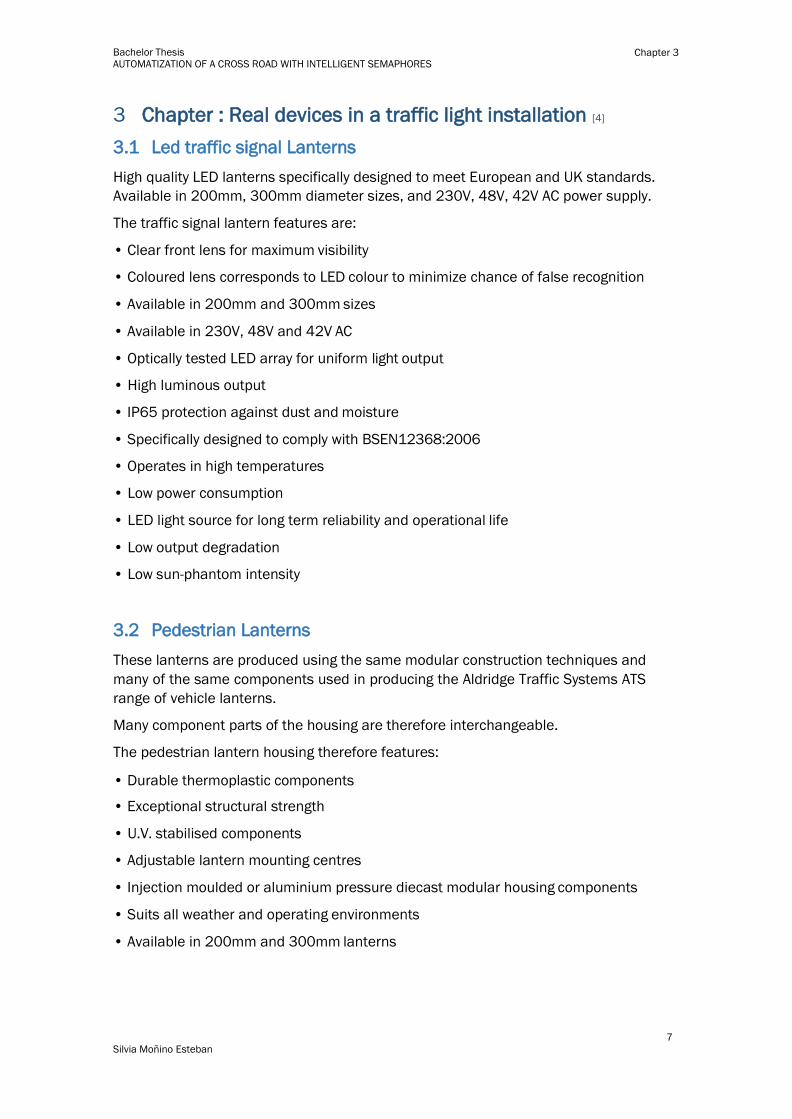
3.1 Led traffic signal Lanterns
High quality LED lanterns specifically designed to meet European and UK standards.
Available in 200mm, 300mm diameter sizes, and 230V, 48V, 42V AC power supply.
The traffic signal lantern features are:
• Clear front lens for maximum visibility
• Coloured lens corresponds to LED colour to minimize chance of false recognition
• Available in 200mm and 300mm sizes
• Available in 230V, 48V and 42V AC
• Optically tested LED array for uniform light output
• High luminous output
• IP65 protection against dust and moisture
• Specifically designed to comply with BSEN12368:2006
• Operates in high temperatures
• Low power consumption
• LED light source for long term reliability and operational life
• Low output degradation
• Low sun-phantom intensity
3.2 Pedestrian Lanterns
These lanterns are produced using the same modular construction techniques and
many of the same components used in producing the Aldridge Traffic Systems ATS
range of vehicle lanterns.
Many component parts of the housing are therefore interchangeable.
The pedestrian lantern housing therefore features:
• Durable thermoplastic components
• Exceptional structural strength
• U.V. stabilised components
• Adjustable lantern mounting centres
• Injection moulded or aluminium pressure diecast modular housing components
• Suits all weather and operating environments
• Available in 200mm and 300mm lanterns

Bachelor Thesis AUTOMATIZATION OF A CROSS ROAD WITH INTELLIGENT SEMAPHORES
Chapter 3
8
Silvia Moñino Esteban
FIGURE 2: PEDESTRIAN SEMAPHORE
SOURCE: WWW.ALDRIDGETRAFFIC.COM
FIGURE 1: TRAFFIC LIGHT
SOURCE: WWW.ALDRIDGETRAFFIC.COM
3.3 Vehicle Presence Detector Controller or Inductor loop [5]
An inductive loop vehicle detector system consists of three components: a loop, loop
extension cable and a detector.
The loop is buried in the traffic lane. The loop is a continuous run of wire that enters and
exits from the same point. The two ends of the loop wire are connected to the loop
extension cable, which in turn connects to the vehicle detector. The detector powers the
loop causing a magnetic field in the loop area. The loop resonates at a constant
frequency that the detector monitors. A base frequency is established when there is no
vehicle over the loop. When a large metal object, such as a vehicle, moves over the loop,
the resonate frequency increases. This increase in frequency is sensed, and it is use to
control traffic lights .
The detector controller features are:
Self tuning range between 20-1500μH
Adjustable sensitivity : 0.02-0.5% ΔL/L
Adjustable frequency between 12-80kHz
Pulse output duration of 150 ms
The presence time is 1 hour for 3% ΔL/L .Also exists permanent presence
PD130 Power requirements :230V AC +/- 15% 48-60Hz
Current requirement :1.5 A a 230 V
Operating temp range : -40oC to +80oC
It is made with High heat ABS blend
Mounting: Shelf or DIN-rail socket
Connector: Single rear mount 11-pin submagnal (86CP11)
FIGURE 3: INDUCTIVE LOOP INSTALLATION AND DETECTOR CONTROLLER
SOURCE: HTTP://WWW.NORTECHCONTROL.COM

Bachelor Thesis AUTOMATIZATION OF A CROSS ROAD WITH INTELLIGENT SEMAPHORES
Chapter 3
9
Silvia Moñino Esteban

10
Silvia Moñino Esteban
Bachelor Thesis AUTOMATIZATION OF A CROSS ROAD WITH INTELLIGENT SEMAPHORES
Chapter 4
4 Chapter : Tools [6] [7]
4.1 Programmable Logic Controller (PLC’s)
A programmable logic controller (PLC) is an industrial solid-state computer control system
that continuously monitors the state of input and output and makes logic-based
decisions based upon a custom program for automated processes or machines.
PLC’s were designed and developed in the late 1960’s to provide the same functions as
relay logic systems. The main reason for the emergence of PLCs was the need to
eliminate the large cost of replacing the complex control systems based on relays and
contactors.
The first PLC was developed by Dick Morley in 1969, it was called model 084, but the
first commercial successful PLC was introduced in 1973 and was designed by Michael
Greenberg. It was the model 184.
PLC provides ease and flexibility of control based on programming and executing logic
instructions.
PLC’s use programmable memory to store instructions and specific functions that
include On/Off control, timing, counting, sequencing, arithmetic, and data handling.
PLC’s are robust and they are prepared to resist very bad conditions like extreme
temperatures, dust, and wetness. They are noise immune.
They are modular, so this allows easy replacement of modules or addition of units.
They had standard input and output connections and they are capable of communicating
with other PLC’s, computers and intelligent devices.
PLC’s operate in real-time which means that an event taking place in the field will result
in an operation or output taking place.
Original equipment manufacturers (OEMs) can provide system updates for a process by
simply sending out a new program
Their programming language is easily understood, so they can be programmed without
much difficulty.
Once a program has been written and tested, it can be downloaded to other PLC’s.
11
Silvia Moñino Esteban
Bachelor Thesis AUTOMATIZATION OF A CROSS ROAD WITH INTELLIGENT SEMAPHORES
Chapter 4
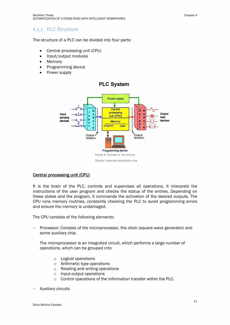
4.1.1 PLC Structure
The structure of a PLC can be divided into four parts:
Central processing unit (CPU)
Input/output modules
Memory
Programming device
Power supply
FIGURE 4: SCHEME OF PLC SYSTEM
SOURCE: WWW.MACHINEDESIGN.COM
Central processing unit (CPU)
It is the brain of the PLC, controls and supervises all operations. It interprets the
instructions of the user program and checks the status of the entries. Depending on
these states and the program, it commands the activation of the desired outputs. The
CPU runs memory routines, constantly checking the PLC to avoid programming errors
and ensure the memory is undamaged.
The CPU consists of the following elements:
Processor: Consists of the microprocessor, the clock (square wave generator) and
some auxiliary chip.
The microprocessor is an integrated circuit, which performs a large number of
operations, which can be grouped into:
o Logical operations
o Arithmetic type operations
o Reading and writing operations
o Input-output operations
o Control operations of the information transfer within the PLC.
Auxiliary circuits
12
Silvia Moñino Esteban
Bachelor Thesis AUTOMATIZATION OF A CROSS ROAD WITH INTELLIGENT SEMAPHORES
Chapter 4
System Monitor Memory: It is a ROM (Read Only Memory) that is programmed and
developed by the manufacturer.
The manufacturer has recorded a series of executive programs, system software and
the processor will access up this to perform the functions.
The routines included are:
o Initialization after power up or reset.
o Test routines and response to malfunction.
o Exchange of information with external units.
o Reading and writing at the interfaces of I /O
Memory
Memory provides permanent storage to the operating system for data used by the CPU.
PLC save here everything it needs to execute the Process Data control task.
Plant signals, inputs and outputs. Internal, bit and word variables. Alphanumeric and
constant data. Control data: User instructions (program) Configuration Programmable
logic controller (operating mode, number of connected I / O...)
The system’s read-only memory (ROM) stores data permanently for the operating system
random access memory (RAM) stores status information for input and output devices,
along with values for timers, counters, and internal devices.
System buses
The internal paths along which the digital signals flow within the PLC are called
buses.
The system has four busses:
– The CPU uses the data bus for sending data between the different elements.
– The address bus to send the addresses of locations for accessing stored data.
– The control bus for signals relating to internal control actions.
– The system bus is used for communications between the I/O ports and the I/O unit.
Programming Device
The programming device is used to enter the required program into the memory of the
processor.
The program is developed in the programming device and then transferred to the memory
unit of the PLC.

13
Silvia Moñino Esteban
Bachelor Thesis AUTOMATIZATION OF A CROSS ROAD WITH INTELLIGENT SEMAPHORES
Chapter 4
Input/Output Unit Module
The input or output modules are the electronic boards that provide the link between the
programmable controller CPU and the system field devices. Through them originates the
exchange of information, either for the purpose of acquiring data, or for the command or
control of the devices present in the process.
The input/output module units are designed with the purpose of simplifying the
connection of input devices and actuators to the PLC.
PLC’s are equipped with standard screw terminals or plugs on every I/O point, allowing
the rapid and simple removal and replacement of a faulty I/O card.
Every input/output module point has a unique address or channel number which is used
during program development to specify the monitoring of an input or the activating of a
particular output within the program.
PLCs employ an optical isolator which uses light to electrically isolate the internal
components from the input and output terminals.
The more common input devices are keyboards, switches, push buttons, relay contacts,
encoders or sensors. Inputs can be either in digital or analog form.
Outputs used to be relays, motor starters, solenoid valves, indicator lights, LED displays
and actuators.
FIGURE 5: TYPICAL INPUTS
SOURCE: WWW.MACHINEDESIGN.COM
FIGURE 6: TYPICAL OUTPUTS
SOURCE: WWW.MACHINEDESIGN.COM

14
Silvia Moñino Esteban
Bachelor Thesis AUTOMATIZATION OF A CROSS ROAD WITH INTELLIGENT SEMAPHORES
Chapter 4
4.1.2 PLC CPU Cycle
PLCs operate by continually scanning programs and repeat this process many times per
second. When a PLC starts, it runs checks on the hardware and software for faults, also
called a self-test. If there are no problems, then the PLC will start the scan cycle.
Scan Input: The PLC takes a snapshot of the inputs and save it in the RAM. Where taking
a snapshot means that, the PLC will save a binary value representing the inputs. This
makes the process faster and avoids cases where an input changes from the start to the
end of the program. This guarantee a constant signal state of inputs during the entire
programme cycle.
Execute Program Logic: The user program sequentially executes the program lines with
their instructions by writing the result of this logic in the process outputs image.
Update Outputs: All output are updated simultaneously based on the process output
image.
FIGURE 7 : CPU CYLCE SOURCE:
WWW.PLCDEV.COM
4.1.3 PLC Programming Language
There are five programming languages .They are defined by the international standard
IEC 61131-3.
Ladder logic: It is the most used PLC languages. In it, symbols represent opening and
closing relays, counters, timers, shift registers, and mathematical operations.
The symbols are arranged into the desired program routine.
Rules in ladder logic are termed “rungs.” Each rung has a single output, but a single
input can be found in more than one rung.
15
Silvia Moñino Esteban
Bachelor Thesis AUTOMATIZATION OF A CROSS ROAD WITH INTELLIGENT SEMAPHORES
Chapter 4
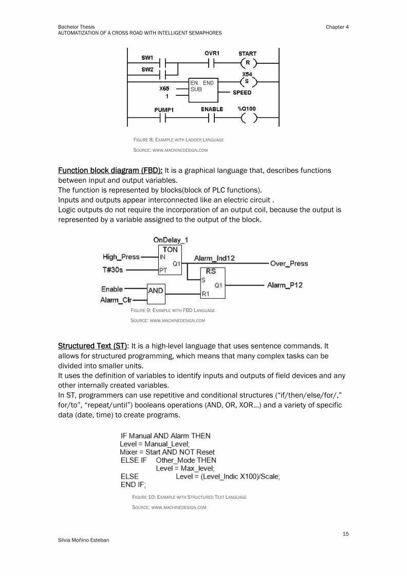
FIGURE 8: EXAMPLE WITH LADDER LANGUAGE
SOURCE: WWW.MACHINEDESIGN.COM
Function block diagram (FBD): It is a graphical language that, describes functions
between input and output variables.
The function is represented by blocks(block of PLC functions).
Inputs and outputs appear interconnected like an electric circuit .
Logic outputs do not require the incorporation of an output coil, because the output is
represented by a variable assigned to the output of the block.
FIGURE 9: EXAMPLE WITH FBD LANGUAGE
SOURCE: WWW.MACHINEDESIGN.COM
Structured Text (ST): It is a high-level language that uses sentence commands. It
allows for structured programming, which means that many complex tasks can be
divided into smaller units.
It uses the definition of variables to identify inputs and outputs of field devices and any
other internally created variables.
In ST, programmers can use repetitive and conditional structures (“if/then/else/for/,”
for/to”, “repeat/until”) booleans operations (AND, OR, XOR...) and a variety of specific
data (date, time) to create programs.
FIGURE 10: EXAMPLE WITH STRUCTURED TEXT LANGUAGE
SOURCE: WWW.MACHINEDESIGN.COM

16
Silvia Moñino Esteban
Bachelor Thesis AUTOMATIZATION OF A CROSS ROAD WITH INTELLIGENT SEMAPHORES
Chapter 4
FIGURE 11: EXAMPLE WITH INSTRUCTION LIST LANGUAGE
Instruction list (IL) :is a low-level language with functions and variables defined by a
simple list. Program control is done by jump instructions and sub-routines with optional
parameters.
SOURCE: WWW.MACHINEDESIGN.COM
Sequential Function Chart (SFC) : It is a graphical programming language based on
GRAFCET.
It uses basic building blocks that run their own sub-routines.
Program files are written in other programming languages. SFC divides large and
complicated programming tasks into smaller units.
The SFC programming framework contains three main elements that organize the
control program:
• Steps (steps)
• Transitions (conditions)
• Actions
FIGURE 12: EXAMPLE WITH SEQUENTIAL FUNCTION CHART
SOURCE: WWW.MACHINEDESIGN.COM
4.1.4 PLC Communications [8]
To get the data from the devices on the field we use industrial communications those
are robust and support extreme conditions. The most used communications are:
Profibus: It specifies the technical and functional characteristics of a system based on a
serial field bus in which decentralized digital controllers can be connected together
from the field level to the control level. There are two types of devices, master devices
and slave devices. Profibus uses a bus topology with termination at both ends for
impedance matching. This technique ensures the coupling and decoupling of stations
during normal operation without affecting the rest. The configuration of Profibus
systems is completely open, i.e devices from different manufacturers can be used in
the same Profibus network. There are different types of profibus: PROFIBUS-DP,
PROFIBUS-PA, PROFIBUS-FMS and PROFIBUS over TCP / IP.
17
Silvia Moñino Esteban
Bachelor Thesis AUTOMATIZATION OF A CROSS ROAD WITH INTELLIGENT SEMAPHORES
Chapter 4
Profinet: Is the acronyms of Process Field Net. It is an industry technical standard for
data communication over Industrial Ethernet designed for collecting data from, and
controlling, equipment in industrial systems, with a particular strength in delivering data
under tight time constraints (on the order of 1ms or less). It is based on Industrial
Ethernet, uses TCP / IP and IT standards.It allows a homogeneous integration of the
fieldbus systems.The standard is maintained and supported by Profibus & Profinet
International.
ASi: The ASi bus (Actuator Sensor Interface).The bus can communicate with intelligent
elements and to be able to transmit data and parameters in addition to binary signals.
The ASi bus is considered to be one of the simplest and least performing communication
systems, so it is used at the field level in the lower part of the automation pyramid. ASi
is an open system defined by the European standard EN 50295 and the standard IEC
62026-2.
Interbus: It is a network of sensors / actuators distributed for systems of manufacture
and control of continuous processes. It is a system with master-slave communication
method, open of high performance, of topology in ring. A system based on Interbus is
composed of a control card, installed in an industrial PC or in a programmable automaton
that communicates with a set of input / output devices. It is a system with European
standard EN50254.It is not supported for any company or organization.
Modbus: It is one of the oldest protocols, it serves to transmit and receive control data
between controllers and sensors through the RS-232 (point-to-point communication)
port. It operates through the master / slave system, and has two essential operating
modes, ASCII mode, and RTU (Remote Terminal Unit) mode. There is the MODBUS plus
version where the RS485 port is used. They use the shielded twisted pair as the physical
medium and the supply voltage is independent for each device. This is a protocol with
limitations.
There are other types of communication to transfer information between the PLC and
other superior system like SCADA, Server or management system. For this
communication we use TCP/IP protocol.
4.1.5 PLC Selection Criteria
Selecting the correct PLC will depend on the needs and size of the automation system.
There are PLCs with varying inputs, outputs, and display options.
There are several requirements to keep in mind when choosing PLCs.
Environmental conditions will affect PLC performance.
If the discrete devices are ac or dc, determine if the PLC can support the required
signal.
Determining CPU requirements is important for calculating the amount of RAM needed
for data manipulation and storage. If data must be stored over a long period of time, CPU
memory must be sized appropriately.
Serial and Ethernet connection-based I/O hardware are typical choices for remote
connections. Remote devices are needed when the PLC is located separately.

18
Silvia Moñino Esteban
Bachelor Thesis AUTOMATIZATION OF A CROSS ROAD WITH INTELLIGENT SEMAPHORES
Chapter 4
4.2 SIEMENS SIMATIC S7-1200 [9]
The S7-1200 programmable logic controller (PLC) provides the flexibility and power to
control a wide variety of devices in support of your automation needs.
The compact design, flexible configuration, and powerful instruction set combine to make
the S7-1200 a perfect solution for controlling a wide variety of applications.
The CPU combines a microprocessor, an integrated power supply, input circuits, and
output circuits in a compact housing to create a powerful PLC.
The S7-1200 family provides a variety of signal modules and signal boards for expanding
the capabilities of the CPU. You can also install additional communication modules to
support other communication protocols.
This family is composed by various models that are different because of number of inputs
and outputs, the power supply and control voltages.
The one we are working with is de model CPU 1214 DC/DC/DC, because is the one that
we have in the university.
FIGURE 13: CPU 1214 SIEMENS
SOURCE: WWW.SIEMENS.COM
The compact CPU 1214C has:
• Integrated power supply DC (24 V DC)
• Integrated 24 V encoder/load current supply: For direct connection of sensors and
encoders. With 400 mA, the output current can also be used as load power supply
• 14 integrated digital inputs 24V DC (current sinking/current sourcing
• 10 integrated digital outputs, 24 V DC or relay
• 2 integrated analog inputs 0 to 10 V
• 2 pulse outputs (PTO) with a frequency of up to 100 kHz
• Pulse-width modulated outputs (PWM) with a frequency of up to 100 kHz
• Integrated Ethernet interface (TCP/IP native, ISO-on-TCP) It could be expanded by:
• 1 signal board (SB)
• 8 signal modules (SM)
• 3 COMMUNICATION modules (CM)

19
Silvia Moñino Esteban
Bachelor Thesis AUTOMATIZATION OF A CROSS ROAD WITH INTELLIGENT SEMAPHORES
Chapter 4
4.3 TIA PORTAL V12
The Totally Integrated Automation (TIA) Portal software provides a user-friendly
environment to develop, edit, and monitor the logic needed to control your application.
The TIA Portal provides the tools for managing and configuring all of the devices in your
project, such as PLCs and HMI devices. As a component of the TIA Portal, STEP 7 Basic
provides two programming languages (LAD and FBD) for convenience and efficiency in
developing the control program for your application. The TIA Portal also provides the tools
for creating and configuring the HMI devices in your project.
The most important steps in TIA Portal that I used are:
● Creating the project
● Configuring the hardware
● Networking the devices
● Programming the PLC
● Loading the configuration data
FIGURE 14: TIA PORTAL APPEARANCE
SOURCE: SILVIA MOÑINO ESTEBAN
4.4 Human Machine Interface (HMI)
The Human Machine Interface (HMI) is the interface between the process and the
operators – in essence an operator’s dashboard. HMIs serve to translate complex
process variables into usable and actionable information. They help in integrating
humans into complex technological systems
This is the primary tool by which operators coordinate and control processes.
Displaying near real-time operational information is the domain of the HMI. Visual
process graphics give meaning and context to the devices used.

20
Silvia Moñino Esteban
Bachelor Thesis AUTOMATIZATION OF A CROSS ROAD WITH INTELLIGENT SEMAPHORES
Chapter 4
FIGURE 15: HMI SCREEN
SOURCE: SILVIA MOÑINO ESTEBAN
4.5 SIMATIC HMI Basic Panel
Siemens count with several families of HMI Panels, so we will choose the one that suits
us best. The choice of the panels depends of the requirements and the complexity of the
program.
The panel we use is the model KTP600 BASIC COLOR PN that belongs to a basic family
of panels. It counts also with six buttons so it has key and touch operations. It has a
screen of 6’’. It support PROFINET protocols.
It is provided with open software sources.
The characteristics of the panel are:
• Display TFT (Thin Film Transistor-Liquid Crystal Display)
• 5.7’’
• 256 colours
• Resolution: 320x240 pixels
• Design as touch screen but includes a keyboard with 6 keys
• Supply power: 24V DC
• Input current: 0.35 A
• Active power input 9W
• Processor: RISC 32-bit
• Protocol: PROFINET
• Protocols (Ethernet): TCP/IP, DHCP, SNMP, DCP and LLDP
FIGURE 16: HMI PANEL KPT600 OF SIEMENS
SOURCE: SILVIA MOÑINO ESTEBAN

21
Silvia Moñino Esteban
Bachelor Thesis AUTOMATIZATION OF A CROSS ROAD WITH INTELLIGENT SEMAPHORES
Chapter 4

22
Silvia Moñino Esteban
Bachelor Thesis AUTOMATIZATION OF A CROSS ROAD WITH INTELLIGENT SEMAPHORES
Chapter 5
5 Chapter : Model
5.1 Explanation of the model
We have ten traffic lights and eight pedestrians semaphores.
In the main street, we have three semaphores each one in a different lane. They are
duplicated since we have it in the two directions. There is an additional light on the
semaphore of the right lane to indicate that you are able to turn.
On the secondary street, we have two semaphores each one in a different lane. They are
duplicated since we have it in the two directions. Also here there is an additional light on
the semaphore of the right lane to indicate that you are able to turn.
In each lane we have a sensor to monitor the traffic.
Then we have two pedestrian crossing in the main street and two more in the secondary.
Every pedestrian crossing have two buttons, one in each side of the sidewalk. Their
function is add more time to cross the street
5.2 Model
FIGURE 17: MODEL OF CROSSROAD
SOURCE: SILVIA MOÑINO ESTEBAN

23
Silvia Moñino Esteban
Bachelor Thesis AUTOMATIZATION OF A CROSS ROAD WITH INTELLIGENT SEMAPHORES
Chapter 5
24
Silvia Moñino Esteban
Bachelor Thesis AUTOMATIZATION OF A CROSS ROAD WITH INTELLIGENT SEMAPHORES
Chapter 6
6 Chapter : Program
6.1 Sequences
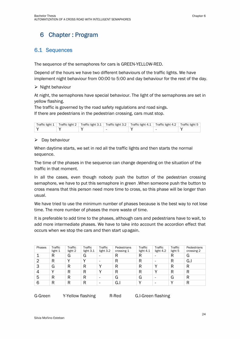
The sequence of the semaphores for cars is GREEN-YELLOW-RED.
Depend of the hours we have two different behaviours of the traffic lights. We have
implement night behaviour from 00:00 to 5:00 and day behaviour for the rest of the day.
Night behaviour
At night, the semaphores have special behaviour. The light of the semaphores are set in
yellow flashing.
The traffic is governed by the road safety regulations and road sings.
If there are pedestrians in the pedestrian crossing, cars must stop.
Traffic light 1 Traffic light 2 Traffic light 3.1 Traffic light 3.2 Traffic light 4.1 Traffic light 4.2 Traffic light 5
Y Y Y - Y - Y
Day behaviour
When daytime starts, we set in red all the traffic lights and then starts the normal
sequence.
The time of the phases in the sequence can change depending on the situation of the
traffic in that moment.
In all the cases, even though nobody push the button of the pedestrian crossing
semaphore, we have to put this semaphore in green .When someone push the button to
cross means that this person need more time to cross, so this phase will be longer than
usual.
We have tried to use the minimum number of phases because is the best way to not lose
time. The more number of phases the more waste of time.
It is preferable to add time to the phases, although cars and pedestrians have to wait, to
add more intermediate phases. We have to take into account the accordion effect that
occurs when we stop the cars and then start up again.
Phases Traffic
light 1 Traffic light 2
Traffic light 3.1
Traffic light 3.2
Pedestrians crossing 1
Traffic light 4.1
Traffic light 4.2
Traffic light 5
Pedestrians crossing 2
1 R G G - R R - R G
2 R Y Y - R R - R G.I
3 G R R Y R R Y R R
4 Y R R Y R R Y R R
5 R R R - G G - G R
6 R R R - G.I Y - Y R
G-Green Y-Yellow flashing R-Red G.I-Green flashing

25
Silvia Moñino Esteban
Bachelor Thesis AUTOMATIZATION OF A CROSS ROAD WITH INTELLIGENT SEMAPHORES
Chapter 6
We have use sensors to monitor the number of cars that are in the junction. Using this
information, we can give more time to the phases that we need. We avoid with this the
accumulation of many cars in one direction that could cause traffic jams.
6.2 Explanation of the programme
The programme starts when the PLC is connected in that moment step E0 is set and is
checked if it is daytime or nighttime.
When START is pushed step E1 is set and all semaphores turn on the red light for five
seconds.
If it is night time, step E2 is set, thus yellow light of each semaphore is blinking, till day
time starts, someone force day or STOP is pressed.
If it is daytime, step E3 is set and daytime sequence starts.
In E3, the cars in main street can circulate straight, semaphores L2 y L3.1 are green, but
semaphore L1 is red, so they cannot turn left, while the cars on secondary street are
stopped, so semaphores L4.1 and L5 are red. The pedestrian cross of the secondary
street is set green so the pedestrians can cross, and the pedestrian cross of main street
is red, so they have to wait. When the time for this step has finished, next step is set, E4
and E3 is reset. If sensors S2S5 and S3S6 have detected many cars or someone had
pressed PP2, Case one or two are set and the time of step E will be extend ten seconds.
In E4, the lights of main street‘s semaphores L2 and L3.1 change to yellow blinking, L1
is red and the green light of the pedestrian semaphore of the secondary street start
blinking. The rest of the semaphores are red, except L3.2 and L4.2 that are off. Therefore,
the cars in main street keep circulating, cars in the first lane still being stopped and cars
in secondary street are stop. The pedestrians may still crossing in P2, but they must to
be attention because red is near to come.
In E5, the semaphore L1 of main street turn green, cars of main street can turn left. The
semaphores L3.2 and L4.2 are set in yellow blinking , cars of main street can turn right
giving way to the cars of the secondary street. The rest of semaphores are red.
Pedestrians semaphores are red. In This step could be added seven seconds if sensor
S1S4 or S3S4 detect many cars, because the setting of Case three or four.
In E6, semaphore L1 turn to yellow blinking, and rest of semaphores are in the same
state than in E5.Cars can turn left in main street and
In E7, cars in main street are stopped, semaphores L1, L2 and L3.1 are red. Semaphores
of secondary street turn green, L4.1 and L5, therefore the cars in secondary street are
circulating. Pedestrians semaphore P1 turn to green, so pedestrians can cross, and the
rest are red. If sensor S7S58 has detected many cars or someone has pressed PP1,
Case five or six are set and the time of step E3 will be extend ten seconds.
In E8, the final step of the daytime sequence, semaphores L4.1 and L5 turn to yellow
flashing. Pedestrian’s semaphore P1 start to blink with green light warning that time to
cross is finishing. Cars in main street and pedestrians in P2 are stopped.
If button of STOP is not pressed after step E8 we return to step E3.If it is pressed we
return to E0.If night-time starts we return to E1.
26
Silvia Moñino Esteban
Bachelor Thesis AUTOMATIZATION OF A CROSS ROAD WITH INTELLIGENT SEMAPHORES
Chapter 6
If someone push STOP in any step of daytime sequence , E0 is going to be set when the
sequence finish, i.e after E8.
6.3 Code Explanation
The programme is built in different blocks, because is the most suitable way since this is
easier to detect problems.
When you create a project in TIA PORTAL the first thing you should do is add the devices
you are going to use. In our case we add the CPU and the HMI that you have in real life.
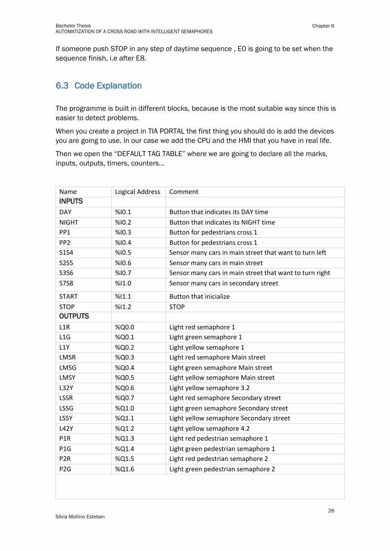
Then we open the “DEFAULT TAG TABLE” where we are going to declare all the marks,
inputs, outputs, timers, counters…
Name Logical Address Comment
INPUTS DAY %I0.1 Button that indicates its DAY time
NIGHT %I0.2 Button that indicates its NIGHT time
PP1 %I0.3 Button for pedestrians cross 1
PP2 %I0.4 Button for pedestrians cross 1
S1S4 %I0.5 Sensor many cars in main street that want to turn left
S2S5 %I0.6 Sensor many cars in main street
S3S6 %I0.7 Sensor many cars in main street that want to turn right
S7S8 %I1.0 Sensor many cars in secondary street
START %I1.1 Button that inicialize
STOP %I1.2 STOP
OUTPUTS L1R %Q0.0 Light red semaphore 1
L1G %Q0.1 Light green semaphore 1
L1Y %Q0.2 Light yellow semaphore 1
LMSR %Q0.3 Light red semaphore Main street
LMSG %Q0.4 Light green semaphore Main street
LMSY %Q0.5 Light yellow semaphore Main street
L32Y %Q0.6 Light yellow semaphore 3.2
LSSR %Q0.7 Light red semaphore Secondary street
LSSG %Q1.0 Light green semaphore Secondary street
LSSY %Q1.1 Light yellow semaphore Secondary street
L42Y %Q1.2 Light yellow semaphore 4.2
P1R %Q1.3 Light red pedestrian semaphore 1
P1G %Q1.4 Light green pedestrian semaphore 1
P2R %Q1.5 Light red pedestrian semaphore 2
P2G %Q1.6 Light green pedestrian semaphore 2

27
Silvia Moñino Esteban
Bachelor Thesis AUTOMATIZATION OF A CROSS ROAD WITH INTELLIGENT SEMAPHORES
Chapter 6
MARKS OF STATES
E0 %M0.0
E1 %M0.1
E2 %M0.2
E3 %M0.3
E4 %M0.4
E5 %M0.5
E6 %M0.6 E7 %M0.7
E8 %M1.0 MARKS OF CASES
Case_1 %M50.0 Pedestrian P2 pressed
Case_2 %M50.1 Many cars sensors Main Street S2/S5&S3/S6
Case_3 %M50.2 Many cars sensors MS right S3/S6
Case_4 %M50.3 Many cars sensors MS left S1/S4
Case_5 %M50.4 Many car sensor Secondary Street S7/S8
Case_6 %M50.5 Pedestrian P1 pressed
AUXILIAR MARKS
START_EDGE %M70.0 Flank START
STOP_RELAY %M20.3 STOP RELAY
DAY/NIGHT %M2.0 Day time
BLINK_100MS %M510.0
PP2_Pressed %M60.0 Button PP2 pressed
PP2_Saved %M60.1 PP2 request
PP1_Pressed %M60.2 Button PP1 pressed
PP1_Saved %M60.3 PP1 request
S2S5_On %M60.4 S2 or/and S5 on
S2S5_Saved %M60.5 S2 or/and S5 request
S1S4_On %M60.6 S1 or/and S4 on
S1S4_Saved %M60.7 S1 or/and S4 request
S3S6_On %M61.0 S3 or/and S6 on
S3S6_Saved %M61.1 S3 or/and S6 request
S7S8_On %M61.2 S7 or/and S8 on
S7S8_Saved %M61.3 S7 or/and S8 request
MARKS FOR THE DURATION OF STEPS
M_E3 %MW204 END TIME STATE
M_E4 %MW206 END TIME STATE
M_E5 %MW208 END TIME STATE
M_E6 %MW210 END TIME STATE
M_E7 %MW212 END TIME STATE
M_E8 %MW214 END TIME STATE

28
Silvia Moñino Esteban
Bachelor Thesis AUTOMATIZATION OF A CROSS ROAD WITH INTELLIGENT SEMAPHORES
Chapter 6
In our case, as we have decided to program in blocks, so we create them.
Startup [OB100]
FIGURE 18: BLOCKS
SOURCE: SILVIA MOÑINO
This block is running at the beginning of the programme.
It set the first step E0 and reset the others and the counter.
We establish here the default times of each phase.
FIGURE 19: BLOCK WITH DEFAULT DURATION OF STEPS
SOURCE: SILVIA MOÑINO ESTEBAN
29
Silvia Moñino Esteban
Bachelor Thesis AUTOMATIZATION OF A CROSS ROAD WITH INTELLIGENT SEMAPHORES
Chapter 6
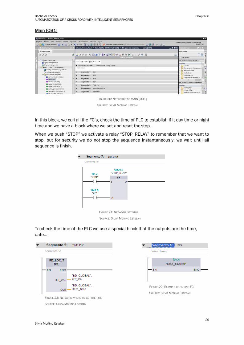
Main [OB1]
FIGURE 20: NETWORKS OF MAIN [OB1]
SOURCE: SILVIA MOÑINO ESTEBAN
In this block, we call all the FC’s, check the time of PLC to establish if it day time or night
time and we have a block where we set and reset the stop.
When we push “STOP” we activate a relay “STOP_RELAY” to remember that we want to
stop, but for security we do not stop the sequence instantaneously, we wait until all
sequence is finish.
FIGURE 21: NETWORK SET STOP
SOURCE: SILVIA MOÑINO ESTEBAN
To check the time of the PLC we use a special block that the outputs are the time,
date…
FIGURE 23: NETWORK WHERE WE GET THE TIME
SOURCE: SILVIA MOÑINO ESTEBAN
FIGURE 22: EXAMPLE OF CALLING FC
SOURCE: SILVIA MOÑINO ESTEBAN

30
Silvia Moñino Esteban
Bachelor Thesis AUTOMATIZATION OF A CROSS ROAD WITH INTELLIGENT SEMAPHORES
Chapter 6
Pulse_generator [FC1
As the name says, here we create the pulse generator that we are going to use in the
programme. We do it with two timers one for de HIGH and one for the LOW.
There is also a counter. We decided not to use time otherwise count pulses. In this way
our steps have a duration of a number of pulses.
The counter only works in the steps that belong to the daytime sequence.
FIGURE 24: COUNTER
SOURCE: SILVIA MOÑINO ESTEBAN
Sequence_control [FC2]
FIGURE 25: NETWORKS OF PULSE GENERATOR
SOURCE: SILVIA MOÑINO ESTEBAN
FIGURE 26: NETWORKS OF FC2
SOURCE: SILVIA MOÑINO ESTEBAN

31
Silvia Moñino Esteban
Bachelor Thesis AUTOMATIZATION OF A CROSS ROAD WITH INTELLIGENT SEMAPHORES
Chapter 6
Here is where we do the transitions between steps and sequences.
Initial step: The condItion to pass to the next step is push the button “START”
FIGURE 27: NETWORKS OF FC2
SOURCE: SILVIA MOÑINO ESTEBAN
Transition between normal steps: This block is used many times, because in each
transition between steps at day time happen the same. We check the counter
and depending on its value, we can pass to the next step or not.
FIGURE 28: NETWORKS EXAMPLE OF TRANSITION BETWEEN STEPS
SOURCE: SILVIA MOÑINO ESTEBAN
Transitio night to day: When day time start or we push the button “DAY” the
sequence have to change.We return to step E1 , where we activate the red
lights.The day-night transition it very similar.
FIGURE 29: NETWORKS OF TRANSITION NIGHT-DAY
SOURCE: SILVIA MOÑINO ESTEBAN
Transition to stop: When we push “STOP” the program return to step E0.It is the
same if we are in daytime or night time
FIGURE 30: NETWORKS OF TRANSITION DAY-STOP
SOURCE: SILVIA MOÑINO ESTEBAN

32
Silvia Moñino Esteban
Bachelor Thesis AUTOMATIZATION OF A CROSS ROAD WITH INTELLIGENT SEMAPHORES
Chapter 6
Light_outputs [FC3]:
In this block we assign to each output the steps where they are set.
FIGURE 31: NETWORKS OF FC3
SOURCE: SILVIA MOÑINO ESTEBAN
FIGURE 32: NETWORKS EXAMPLE OF LIGHT ASSIGNATION
SOURCE: SILVIA MOÑINO ESTEBAN
Case_control [FC4]
In this block, we control the cases. A case it a situation where an event is happening and
default sequence is being modified. We have six cases; they are group by two, because
they have the same consequences.
There are two types of cases .One that is caused because a sensor of monitoring cars it
is set, that means there are many cars, and other that is causes because some
pedestrian has push button for pedestrian’s crossing. When a case is set we add time to
the step that request it.
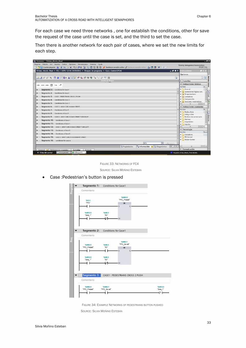
In this block we have twenty-two networks
33
Silvia Moñino Esteban
Bachelor Thesis AUTOMATIZATION OF A CROSS ROAD WITH INTELLIGENT SEMAPHORES
Chapter 6
For each case we need three networks , one for establish the conditions, other for save
the request of the case until the case is set, and the third to set the case.
Then there is another network for each pair of cases, where we set the new limits for
each step.
FIGURE 33: NETWORKS OF FC4
SOURCE: SILVIA MOÑINO ESTEBAN
Case :Pedestrian’s button is pressed
FIGURE 34: EXAMPLE NETWORKS OF PEDESTRIANS BUTTON PUSHED
SOURCE: SILVIA MOÑINO ESTEBAN
34
Silvia Moñino Esteban
Bachelor Thesis AUTOMATIZATION OF A CROSS ROAD WITH INTELLIGENT SEMAPHORES
Chapter 6
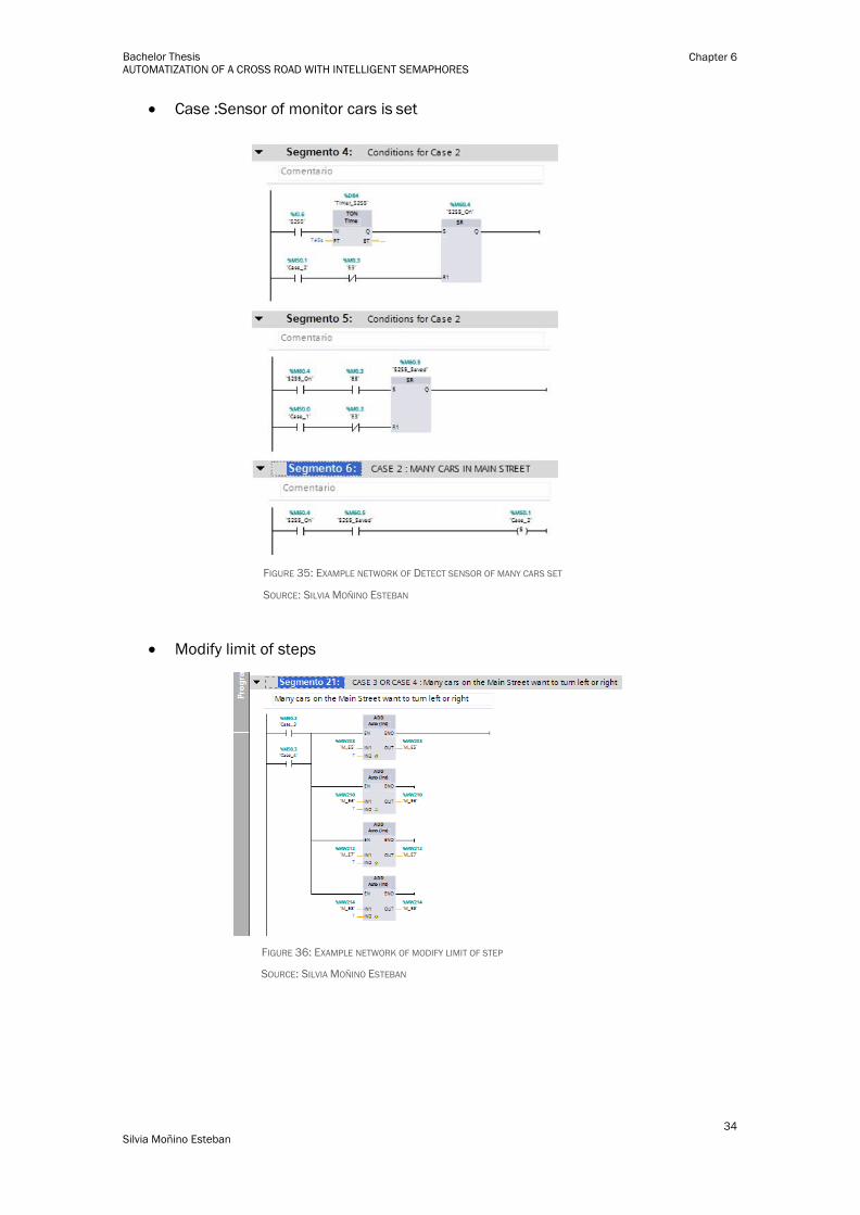
Case :Sensor of monitor cars is set
FIGURE 35: EXAMPLE NETWORK OF DETECT SENSOR OF MANY CARS SET
SOURCE: SILVIA MOÑINO ESTEBAN
Modify limit of steps
FIGURE 36: EXAMPLE NETWORK OF MODIFY LIMIT OF STEP
SOURCE: SILVIA MOÑINO ESTEBAN

35
Silvia Moñino Esteban
Bachelor Thesis AUTOMATIZATION OF A CROSS ROAD WITH INTELLIGENT SEMAPHORES
Chapter 6
36
Silvia Moñino Esteban
Bachelor Thesis AUTOMATIZATION OF A CROSS ROAD WITH INTELLIGENT SEMAPHORES
Chapter 7
7 ANNEXED
7.1 Bibliography
[1] http://www.kbrhorse.net
[2] www.dgt.es/Galerias/la-dgt/.../TEMA_24_GESTION_TECNICA_TRAFICO.doc
[3] http://www.morail.org
[4] http://www.aldridgetraffic.com
[5] http://www.marshproducts.com
[6] http://www.machinedesign.com
[7] University Notes of “AUTOMATIC REGULATION” and “INDUSTRIAL AUTOMATION”
[7] Programación de autómatas con STEP 7: enfoque práctico – Pablo San Segundo –
Madrid 2011
[8] Comunicaciones Industriales (Industrial Communications) – Vicente Guerrero,Luis
Martínez y Ramón L. Yuste
[9] https://www.siemens.com
These webs sites below have been used for photos:
http://www.nortechcontrol.com
https://support.industry.siemens.com
http://www.infoplc.net/
http://www.ieec.uned.es
http://www.plcdev.com
37
Silvia Moñino Esteban
Bachelor Thesis AUTOMATIZATION OF A CROSS ROAD WITH INTELLIGENT SEMAPHORES
Chapter 7
7.2 Figures
FIGURE 1: PEDESTRIAN SEMAPHORE ....................................................................................... 8
FIGURE 2: TRAFFIC LIGHT ..................................................................................................... 8
FIGURE 3: INDUCTIVE LOOP INSTALLATION AND DETECTOR CONTROLLER ..................... 8
FIGURE 4: SCHEME OF PLC SYSTEM ................................................................................. 11
FIGURE 5: TYPICAL INPUTS ................................................................................................. 13
FIGURE 6: TYPICAL OUTPUTS .............................................................................................. 13
FIGURE 7 : CPU CYLCE ........................................................................................................ 14
FIGURE 8: EXAMPLE WITH LADDER LANGUAGE ................................................................ 15
FIGURE 9: EXAMPLE WITH FBD LANGUAGE ....................................................................... 15
FIGURE 10: EXAMPLE WITH STRUCTURED TEXT LANGUAGE ............................................ 15
FIGURE 11: EXAMPLE WITH INSTRUCTION LIST LANGUAGE ............................................ 16
FIGURE 12: EXAMPLE WITH SEQUENTIAL FUNCTION CHART ........................................... 16
FIGURE 13: CPU 1214 SIEMENS ........................................................................................... 18
FIGURE 14: TIA PORTAL APPEARANCE ............................................................................... 19
FIGURE 15: HMI SCREEN .................................................................................................... 20
FIGURE 16: HMI PANEL KPT600 OF SIEMENS .................................................................. 20
FIGURE 17: MODEL OF CROSSROAD ................................................................................. 22
FIGURE 18: BLOCKS ............................................................................................................ 28
FIGURE 19: BLOCK WITH DEFAULT DURATION OF STEPS ................................................ 28
FIGURE 20: NETWORKS OF MAIN [OB1] ............................................................................... 29
FIGURE 21: NETWORK SET STOP ....................................................................................... 29
FIGURE 22: EXAMPLE OF CALLING FC................................................................................... 29
FIGURE 23: NETWORK WHERE WE GET THE TIME .............................................................. 29
FIGURE 24: COUNTER ......................................................................................................... 30
FIGURE 25: NETWORKS OF PULSE GENERATOR ............................................................... 30
FIGURE 26: NETWORKS OF FC2 ......................................................................................... 30
FIGURE 27: NETWORKS OF FC2 ......................................................................................... 31
FIGURE 28: NETWORKS EXAMPLE OF TRANSITION BETWEEN STEPS ............................. 31
FIGURE 29: NETWORKS OF TRANSITION NIGHT-DAY ........................................................ 31
FIGURE 30: NETWORKS OF TRANSITION DAY-STOP .......................................................... 31
FIGURE 31: NETWORKS OF FC3 ......................................................................................... 32
FIGURE 32: NETWORKS EXAMPLE OF LIGHT ASSIGNATION ............................................. 32
FIGURE 33: NETWORKS OF FC4 ......................................................................................... 33
FIGURE 34: EXAMPLE NETWORKS OF PEDESTRIANS BUTTON PUSHED ......................... 33
FIGURE 35: EXAMPLE NETWORK OF DETECT SENSOR OF MANY CARS SET .................. 34
FIGURE 36: EXAMPLE NETWORK OF MODIFY LIMIT OF STEP .......................................... 34

38
Silvia Moñino Esteban
Bachelor Thesis AUTOMATIZATION OF A CROSS ROAD WITH INTELLIGENT SEMAPHORES
Chapter 7
7.3 Glossary
DC Direct Current
AC Alternating Current
V Volts
PLC Programmable Logic Controller
mA Milliamps-> It is a submultiple of amps that means 0,001 amps
mm Millimetres -> It is a submultiple of metres that means 0,001 metres
KHz KiloHertz -> It is a multiple that means 1000 Hertz
μH MicroHenry -> It is a submultiple of henry that means 0,001 henry
ISO International Standards Organization
PWM Pulse Width Modulation
TCP Transmission Control Protocol
IP Internet Protocol
I/O Inputs/Outputs
HMI Human Machine Interface
CPU Central Processing Unit

39
Silvia Moñino Esteban
Bachelor Thesis AUTOMATIZATION OF A CROSS ROAD WITH INTELLIGENT SEMAPHORES
Chapter 7