tp9kac-tux (mar 2019) - tuxedoautoequip.com
TRANSCRIPT
Mar 2019
TP9KAC-TUX Two-Post Clear Floor Lift
(Asymmetric) 9,000 lbs. Capacity (2,250 lbs. Max per Arm)
INSTALLATION & OPERATION MANUAL
2 TP9KAC-TUX
Mar 2019
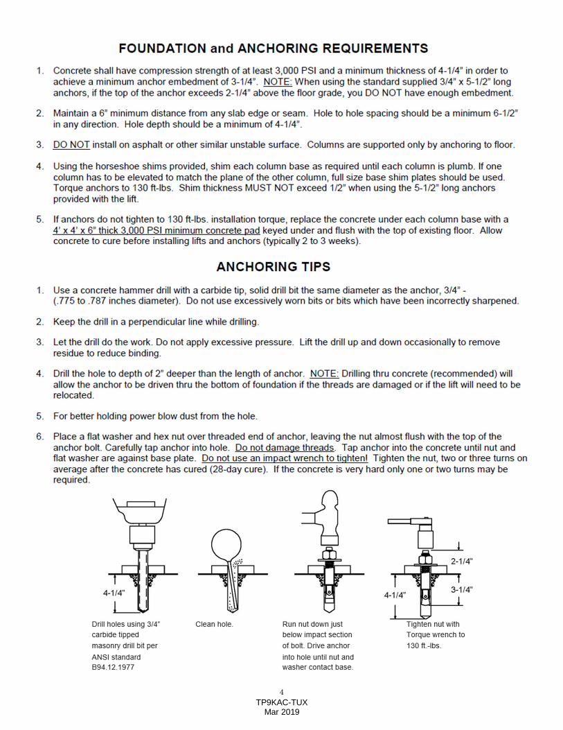
IMPORTANT NOTES
READ THE INSTALLATION AND OPERATION MANUAL IN ITS ENTIRETY BEFORE ATTEMPTING TO INSTALL THE LIFT.
· Do not install this lift on any surface other than concrete, conforming to minimum specifications.
· Do not install this lift over expansion joints or cracks. Check with building architect.
· Do not install this lift on a second floor with a basement beneath without written authorization from
building architect.
· Do not install this lift outdoors unless special consideration has been made to protect the power unit
from inclement weather conditions.
· A level floor is recommended for proper installation and operation. Concrete should be a minimum
of 4-1/4” thickness and 3,000 psi tensile strength with steal or fiber mesh reinforcement.
· The lift is intended to raise the entire body of the vehicle. Do not attempt to lift only part of the
vehicle. Improper use of this equipment could result in damage to the lift, yourself or other property.
· The lift is intended to lift vehicles only. It is not designed to lift any person or equipment containing
persons.
· Users of this equipment should be qualified, responsible and should follow the operation and safety
guidelines set forth in this manual.
· For specifications on concrete pads, please call for technical assistance.
· Improper installation can cause damage or injury. The Manufacturer will NOT assume liability for
loss or damage of any kind, expressed or implied, resulting from improper installation or use of this
product.
DEFINITION Surface Mounted, Two-Post, Clear-Floor Lift w/ Overhead Beam, Hydraulic ‘chain-over’ Drive, 9,000 lbs. Capacity.
The name / model numbers are designated below:
· Model number TP9KAC-TUX - Asymmetric Swing Arm configuration
BASIC SPECIFICATIONS
Model Description (Clear Floor)
Capacity Lifting Time Overall Height
Overall Width
Lifting Height
Between Columns
TP9KAC-TUX Asymmetric 9,000 lbs. 50 Sec 142-11/16” 141” 72” 110-7/16”
3 TP9KAC-TUX
Mar 2019
PREPARATION The installation of this lift is relatively simple and can be accomplished by 2 men in a few hours. The
following tools and equipment are needed:
· 12 quarts of Non-Detergent / Non-Foaming Hydraulic Oil - SAE-10, AW 32 or equivalent
· Chalk line and 12’ Tape Measure
· 4ft. Level
· Rotary Hammer Drill with 3/4” Masonry Drill Bit. (Core Drill Rebar Cutter also recommended)
· Hammer and Hex Key Wrench Set
· Metric Sockets and Open Wrench set - 13mm-30mm
· Medium Adjustable Wrench and Medium Pipe Wrench
· Crow Bar for Shim Installation and Medium Flat Screwdriver
· Locking, Needle Nose and Snap Ring Pliers
GENERAL INFORMATION
1. Carefully remove the crating and packing materials.
CAUTION! Be careful when cutting steel banding material as items may become loose and fall
causing personal harm or injury.
2. Identify the components and check for damage or shortages.
Please contact your distributor immediately, if any damages or shortages are discovered.
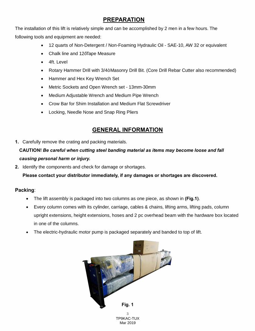
Packing: · The lift assembly is packaged into two columns as one piece, as shown in (Fig.1).
· Every column comes with its cylinder, carriage, cables & chains, lifting arms, lifting pads, column
upright extensions, height extensions, hoses and 2 pc overhead beam with the hardware box located
in one of the columns.
· The electric-hydraulic motor pump is packaged separately and banded to top of lift.
Fig. 1
4 TP9KAC-TUX
Mar 2019
5 TP9KAC-TUX
Mar 2019
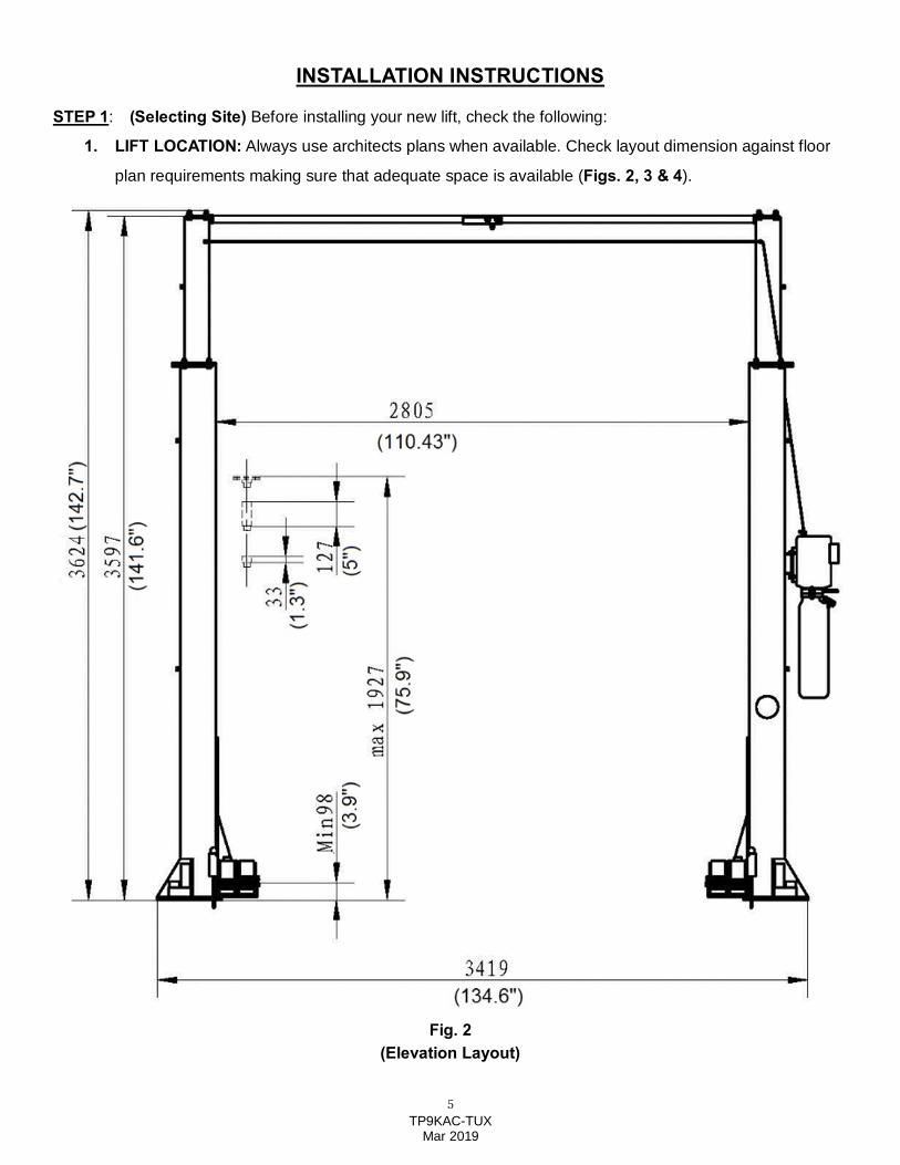
INSTALLATION INSTRUCTIONS
STEP 1: (Selecting Site) Before installing your new lift, check the following:
1. LIFT LOCATION: Always use architects plans when available. Check layout dimension against floor
plan requirements making sure that adequate space is available (Figs. 2, 3 & 4).
Fig. 2 (Elevation Layout)
6 TP9KAC-TUX
Mar 2019
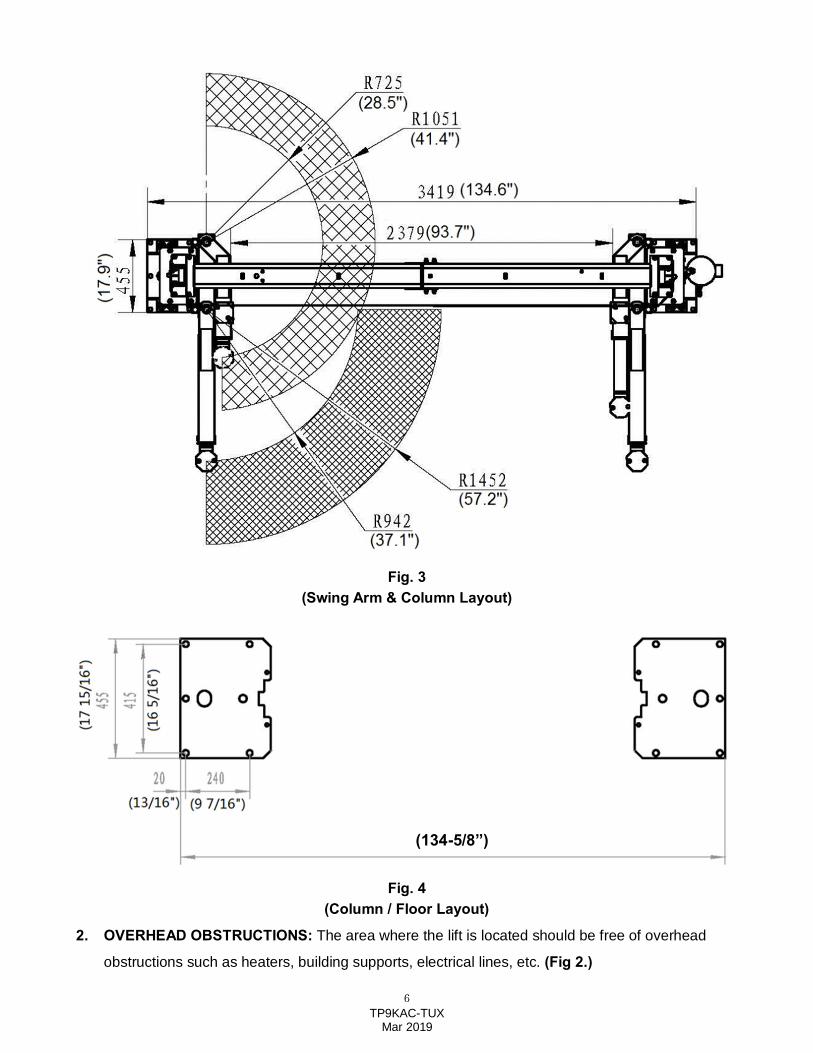
Fig. 3
(Swing Arm & Column Layout)
Fig. 4 (Column / Floor Layout)
2. OVERHEAD OBSTRUCTIONS: The area where the lift is located should be free of overhead
obstructions such as heaters, building supports, electrical lines, etc. (Fig 2.)
(134-5/8”)
7 TP9KAC-TUX
Mar 2019
3. DEFECTIVE CONCRETE: Visually inspect the site where the lifts will be installed and check for
cracked or defective concrete. (Details on Page 4)
4. FLOOR REQUIREMENTS: The lift should be installed on a 3000 PSI concrete with minimum of 4-1/4”
thickness. The Floor should be level with-in gradients of ≦1/4” within area of the two columns = 135” x
18”).
(See Details for Foundation Anchoring Requirements & Anchoring Tips on Page 4)
STEP 2: (Unloading & Unpacking)
1. After unloading the lift, place it near the intended installation location.
2. Remove the shipping bands and packing materials from the unit.
3. Remove the packing brackets and bolts holding the two columns together. (Do not discard bolts, they
may be used in the assembly of the lift)
4. Take out the column ‘upright’ extensions, lifting arms, lifting pads, height extensions, hardware box,
hoses, etc., from the column. Check the quantity of each item with the parts list. If anything is missing,
please contact your dealer at once.
STEP 3: (Site Layout)
1. Determine which side will be the approach side.
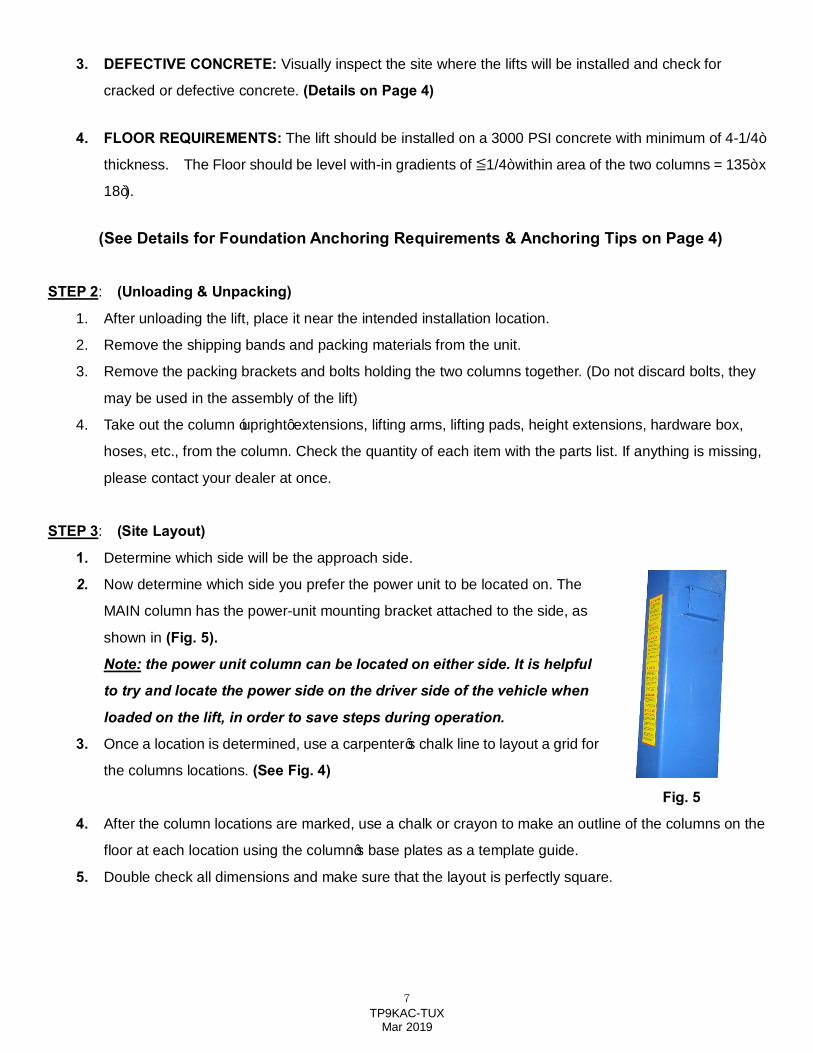
2. Now determine which side you prefer the power unit to be located on. The
MAIN column has the power-unit mounting bracket attached to the side, as
shown in (Fig. 5).
Note: the power unit column can be located on either side. It is helpful
to try and locate the power side on the driver side of the vehicle when
loaded on the lift, in order to save steps during operation.
3. Once a location is determined, use a carpenter’s chalk line to layout a grid for
the columns locations. (See Fig. 4)
Fig. 5
4. After the column locations are marked, use a chalk or crayon to make an outline of the columns on the
floor at each location using the column’s base plates as a template guide.
5. Double check all dimensions and make sure that the layout is perfectly square.
8 TP9KAC-TUX
Mar 2019
STEP 4: (Installing MAIN COLUMN w/ Power Unit Bracket)
1. Before proceeding, double check measurements and make certain that the bases of each column are
square and aligned with the chalk line.
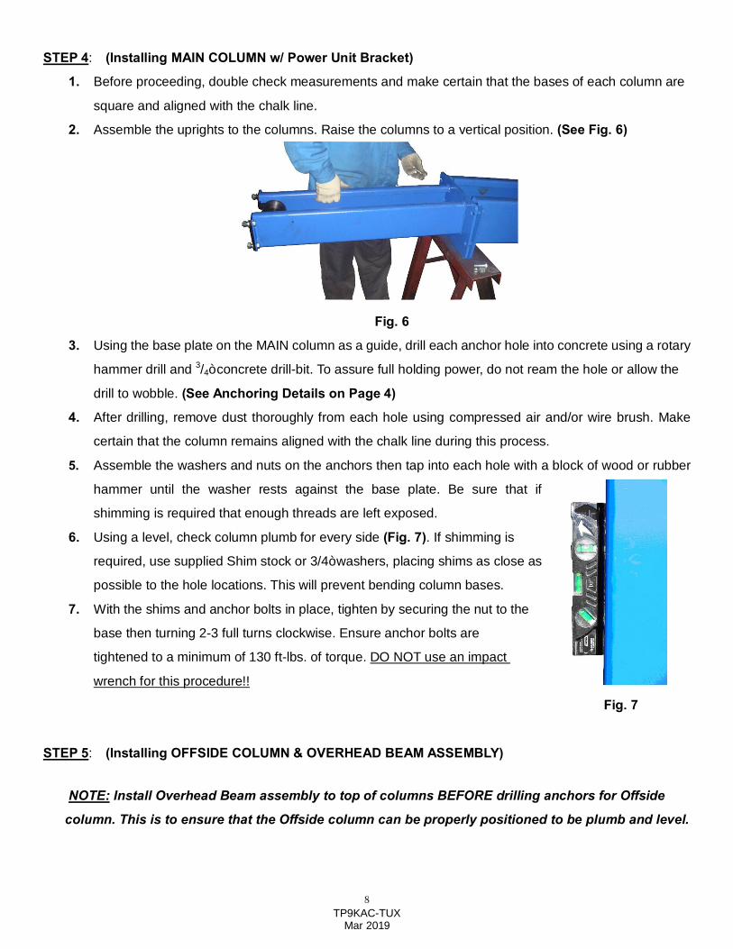
2. Assemble the uprights to the columns. Raise the columns to a vertical position. (See Fig. 6)
Fig. 6
3. Using the base plate on the MAIN column as a guide, drill each anchor hole into concrete using a rotary
hammer drill and 3/4” concrete drill-bit. To assure full holding power, do not ream the hole or allow the
drill to wobble. (See Anchoring Details on Page 4)
4. After drilling, remove dust thoroughly from each hole using compressed air and/or wire brush. Make
certain that the column remains aligned with the chalk line during this process.
5. Assemble the washers and nuts on the anchors then tap into each hole with a block of wood or rubber
hammer until the washer rests against the base plate. Be sure that if
shimming is required that enough threads are left exposed.
6. Using a level, check column plumb for every side (Fig. 7). If shimming is
required, use supplied Shim stock or 3/4” washers, placing shims as close as
possible to the hole locations. This will prevent bending column bases.
7. With the shims and anchor bolts in place, tighten by securing the nut to the
base then turning 2-3 full turns clockwise. Ensure anchor bolts are
tightened to a minimum of 130 ft-lbs. of torque. DO NOT use an impact
wrench for this procedure!!
Fig. 7
STEP 5: (Installing OFFSIDE COLUMN & OVERHEAD BEAM ASSEMBLY)
NOTE: Install Overhead Beam assembly to top of columns BEFORE drilling anchors for Offside
column. This is to ensure that the Offside column can be properly positioned to be plumb and level.
9 TP9KAC-TUX
Mar 2019
1. Raise OFFSIDE column and position at the designated chalk locations, ensuring the Column ‘upright’
Extension is pre-installed to the top of the OFFSIDE column.
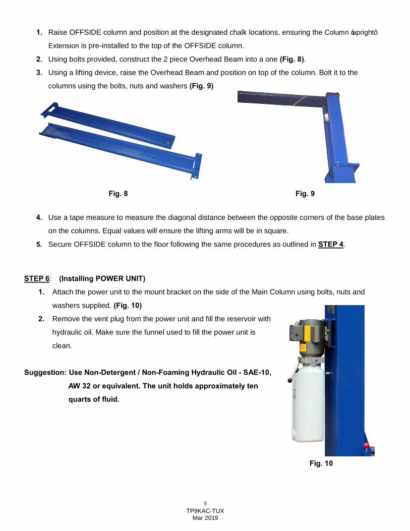
2. Using bolts provided, construct the 2 piece Overhead Beam into a one (Fig. 8).
3. Using a lifting device, raise the Overhead Beam and position on top of the column. Bolt it to the
columns using the bolts, nuts and washers (Fig. 9)
Fig. 8 Fig. 9
4. Use a tape measure to measure the diagonal distance between the opposite corners of the base plates
on the columns. Equal values will ensure the lifting arms will be in square.
5. Secure OFFSIDE column to the floor following the same procedures as outlined in STEP 4.
STEP 6: (Installing POWER UNIT)
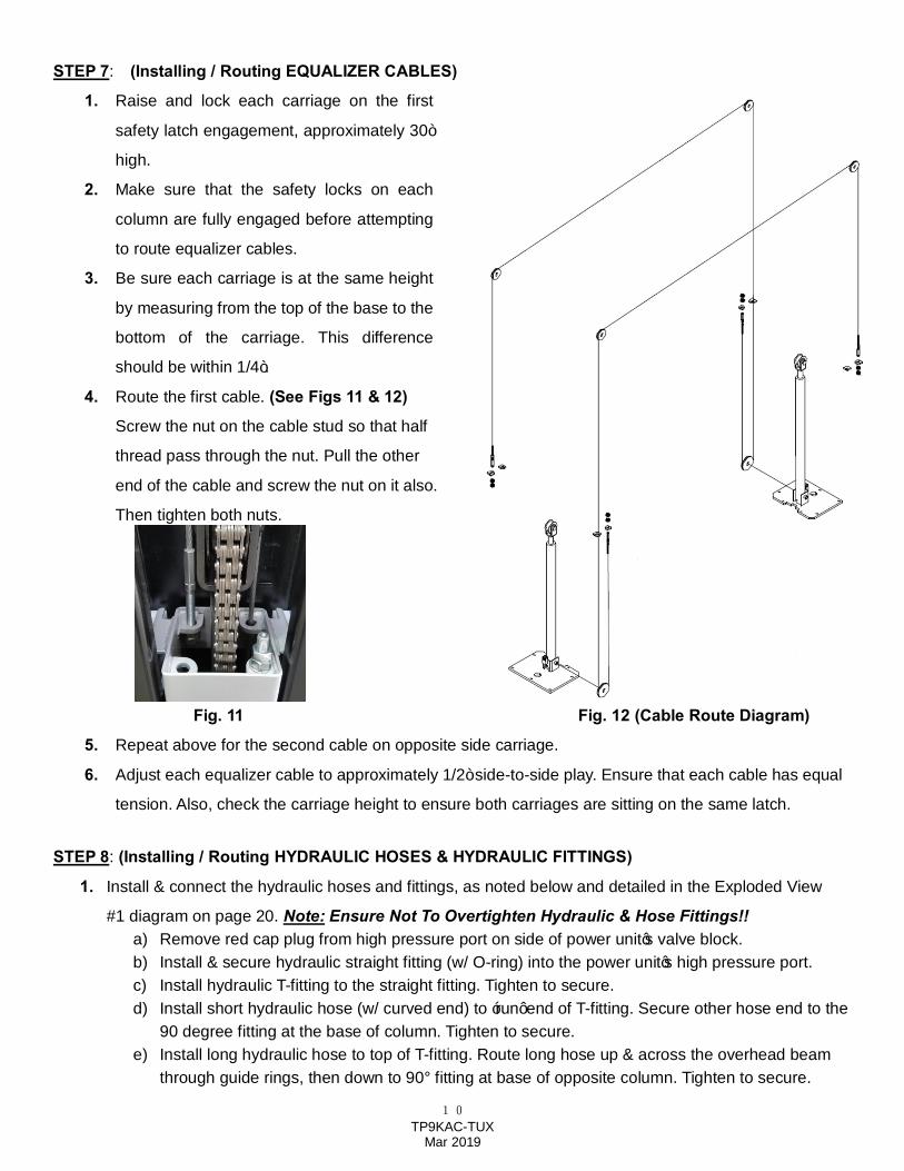
1. Attach the power unit to the mount bracket on the side of the Main Column using bolts, nuts and
washers supplied. (Fig. 10)
2. Remove the vent plug from the power unit and fill the reservoir with
hydraulic oil. Make sure the funnel used to fill the power unit is
clean.
Suggestion: Use Non-Detergent / Non-Foaming Hydraulic Oil - SAE-10,
AW 32 or equivalent. The unit holds approximately ten
quarts of fluid.
Fig. 10
10 TP9KAC-TUX
Mar 2019
STEP 7: (Installing / Routing EQUALIZER CABLES)
1. Raise and lock each carriage on the first
safety latch engagement, approximately 30”
high.
2. Make sure that the safety locks on each
column are fully engaged before attempting
to route equalizer cables.
3. Be sure each carriage is at the same height
by measuring from the top of the base to the
bottom of the carriage. This difference
should be within 1/4”.
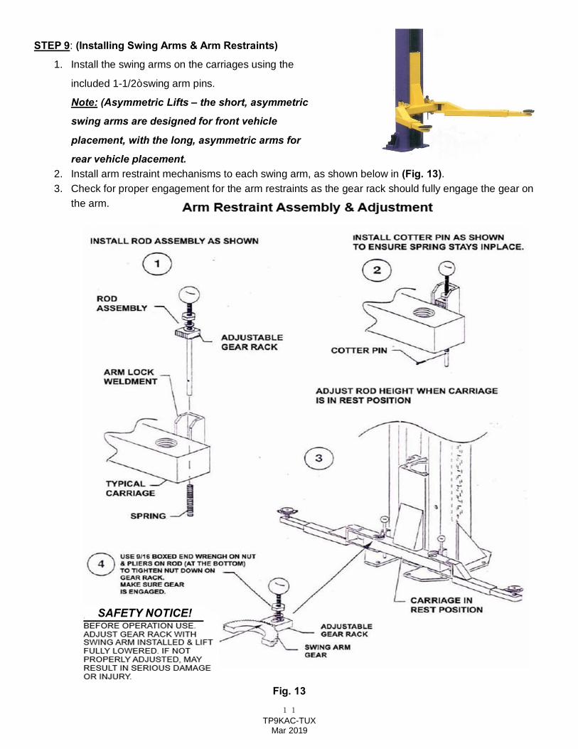
4. Route the first cable. (See Figs 11 & 12)
Screw the nut on the cable stud so that half
thread pass through the nut. Pull the other
end of the cable and screw the nut on it also.
Then tighten both nuts.
Fig. 11 Fig. 12 (Cable Route Diagram)
5. Repeat above for the second cable on opposite side carriage.
6. Adjust each equalizer cable to approximately 1/2” side-to-side play. Ensure that each cable has equal
tension. Also, check the carriage height to ensure both carriages are sitting on the same latch.
STEP 8: (Installing / Routing HYDRAULIC HOSES & HYDRAULIC FITTINGS)
1. Install & connect the hydraulic hoses and fittings, as noted below and detailed in the Exploded View
#1 diagram on page 20. Note: Ensure Not To Overtighten Hydraulic & Hose Fittings!! a) Remove red cap plug from high pressure port on side of power unit’s valve block. b) Install & secure hydraulic straight fitting (w/ O-ring) into the power unit’s high pressure port. c) Install hydraulic T-fitting to the straight fitting. Tighten to secure. d) Install short hydraulic hose (w/ curved end) to ‘run’ end of T-fitting. Secure other hose end to the
90 degree fitting at the base of column. Tighten to secure. e) Install long hydraulic hose to top of T-fitting. Route long hose up & across the overhead beam
through guide rings, then down to 90° fitting at base of opposite column. Tighten to secure.
11 TP9KAC-TUX
Mar 2019
STEP 9: (Installing Swing Arms & Arm Restraints)
1. Install the swing arms on the carriages using the
included 1-1/2” swing arm pins.
Note: (Asymmetric Lifts – the short, asymmetric
swing arms are designed for front vehicle
placement, with the long, asymmetric arms for
rear vehicle placement. 2. Install arm restraint mechanisms to each swing arm, as shown below in (Fig. 13). 3. Check for proper engagement for the arm restraints as the gear rack should fully engage the gear on
the arm.
Fig. 13
SAFETY NOTICE!
12 TP9KAC-TUX
Mar 2019
STEP 10: (Electrical Connection to POWER UNIT & OVERHEAD LIMIT SWITCH)
1. Have a certified electrician make the electrical connection to the power unit. Use a separate circuit for
each power unit, as shown below in (Fig. 14).
Fig. 14
IMPORTANT! The wiring must comply with local code. Protect each circuit with time delay fuse or
circuit breaker. For 208V-230V single phase, use 20 amp fuse.
WARNING!! Never operate the motor in line voltage less than 208VAC as motor damage may occur.
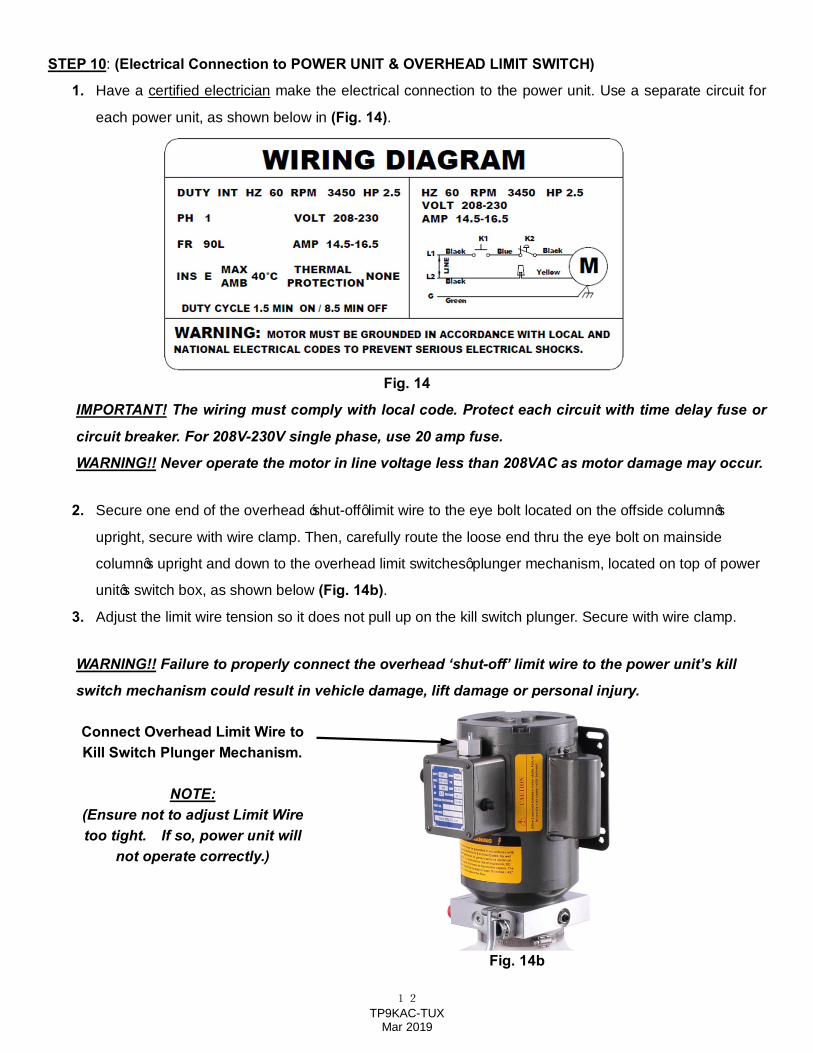
2. Secure one end of the overhead ‘shut-off’ limit wire to the eye bolt located on the offside column’s
upright, secure with wire clamp. Then, carefully route the loose end thru the eye bolt on mainside
column’s upright and down to the overhead limit switches’ plunger mechanism, located on top of power
unit’s switch box, as shown below (Fig. 14b).
3. Adjust the limit wire tension so it does not pull up on the kill switch plunger. Secure with wire clamp.
WARNING!! Failure to properly connect the overhead ‘shut-off’ limit wire to the power unit’s kill
switch mechanism could result in vehicle damage, lift damage or personal injury.
Fig. 14b
Connect Overhead Limit Wire to Kill Switch Plunger Mechanism.
NOTE: (Ensure not to adjust Limit Wire too tight. If so, power unit will
not operate correctly.)
13 TP9KAC-TUX
Mar 2019
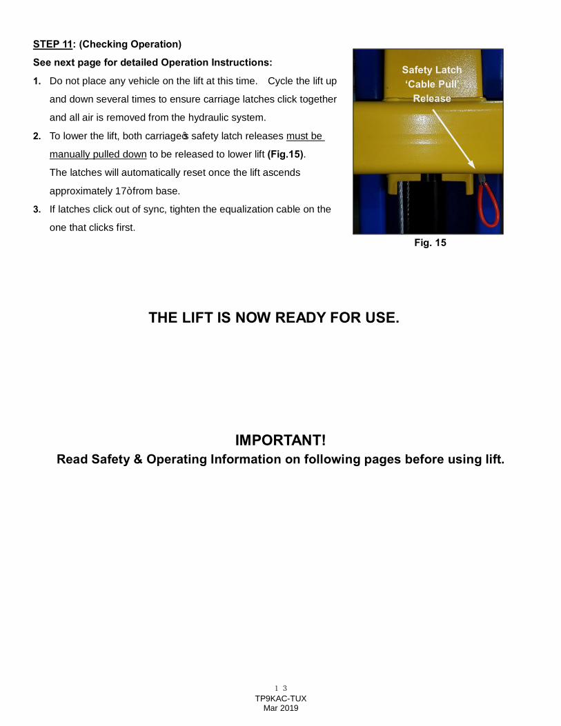
STEP 11: (Checking Operation)
See next page for detailed Operation Instructions:
1. Do not place any vehicle on the lift at this time. Cycle the lift up
and down several times to ensure carriage latches click together
and all air is removed from the hydraulic system.
2. To lower the lift, both carriage’s safety latch releases must be
manually pulled down to be released to lower lift (Fig.15).
The latches will automatically reset once the lift ascends
approximately 17” from base.
3. If latches click out of sync, tighten the equalization cable on the
one that clicks first.
THE LIFT IS NOW READY FOR USE.
IMPORTANT! Read Safety & Operating Information on following pages before using lift.
Safety Latch ‘Cable Pull’
Release
Fig. 15
14 TP9KAC-TUX
Mar 2019
OPERATION INSTRUCTIONS
RAISE LIFT
1. Read operating and safety manuals before using lift.
2. Always lift a vehicle according to the manufacturers recommended lifting points
3. Position vehicle between columns, as equally as possible.
4. Adjust swing arms so that the vehicle is positioned with the center of gravity midway between pads.
5. Use truck adapters as needed. Never exceed 9” of pad height.
6. Raise the lift by pressing button on power unit until support pads contact the underside of the vehicle
and re-check to make sure vehicle is secure.
7. Raise vehicle to desired working height. The latch mechanism will ‘trip over’ when the lift raises and drop
into each latch stop.
8. Press lowering ‘release’ lever on Power Unit to lower lift onto latches, to lock the lift in the proper safety
position.
Note: Always lock the lift before going under the vehicle. Never allow anyone to go under the lift
when raising or lowering. Read the safety procedures in the manual.
LOWER LIFT
1. Ensure tools, trays, stands and/or personnel are removed from under vehicle.
2. Slightly raise lift until the safety latches clear column locks.
3. Pull latch release cables on both sides.
WARNING: ALWAYS RELEASE BOTH SAFETY LATCHES ON EACH SIDE
4. Press the release lever on the power unit to lower the lift.
5. Before removing vehicle from lift area, position lift arms and supports to provide an unobstructed exit.
WARNING: NEVER DRIVE OVER LIFT’S ARMS.
Note: It is normal for an empty lift to lower slowly, it may be necessary to add weight.
15 TP9KAC-TUX
Mar 2019
SAFETY PROCEDURES
· Never allow unauthorized persons to operate lift. Thoroughly train new employees in the operation and care of
the lift.
· Caution: the power unit operates at high pressure.
· Remove passengers before raising vehicle.
· Prohibit unauthorized persons from being in shop area while lift is in use.
· Total lift capacity is 9,000 lbs. with 2,250 lbs. per arm pad. Never exceed the capacity.
· When approaching the lift with a vehicle, center the vehicle between the columns so that the tires will clear the
swing arms easily. Slowly drive the vehicle up between the columns. Have someone outside the vehicle guide the
driver.
· Always lift vehicle using all four arms. Never use lift to raise one end or one side of vehicle.
· Prior to lifting vehicle, walk around the lift and check for any objects that might interfere with the operation of lift
and safety latches; tools, air hoses, shop equipment.
· Raise vehicles about 3” and check stability by rocking.
· Prior to lowering vehicle, walk around the lift and check for any objects that might interfere with the operation of
lift and safety latches; tools, air hoses, shop equipment.
· After lowering lift, swing the arms out of the path and slowly drive the vehicle out. Have someone outside the
vehicle guide the driver.
ALWAYS LOCK THE LIFT BEFORE GOING UNDER THE VEHICLE. NEVER ALLOW ANYONE TO GO UNDER THE LIFT WHEN RAISING OR LOWERING.
OWNER / EMPLOYER RESPONSIBILITIES · Shall establish procedures to periodically maintain, inspect and care for the lift in accordance with the
manufacturer’s recommended procedures to ensure its’ continued safe operations.
· Shall provide necessary lockout of energy sources per ANSIZ244.1 –1982 before beginning any lift repairs.
· Shall not modify the lift in any manner without prior written consent of the manufacturer.
MAINTENANCE SCHEDULE The following periodic maintenance is the suggested minimum requirements and minimum intervals; accumulated
hours or monthly period, whichever comes sooner. If you hear a noise or see any indication of impending failure -
cease operation immediately – inspect, correct and / or replace parts as required.
16 TP9KAC-TUX
Mar 2019
WARNING!! OSHA AND ANSI REQUIRE USERS TO INSPECT LIFTING EQUIPMENT AT THE START OF EVERY SHIFT. THESE AND OTHER PERIODIC INSPECTIONS ARE THE RESPONSIBILITY OF THE USER. DAILY PRE-OPERATION CHECK (8 HOURS)
The user should perform Daily check. Daily check of the safety latch system is very important to prevent expensive
property damage, lost production time, serious personal injury and even death.
· Check safety lock audibly and visually while in operation
· Check safety latches for free movement and full engagement with rack.
· Check hydraulic connections, and hoses for leakage.
· Check cables connections for bends, cracks and proper tension.
· Check for frayed cables in both raised and lowered position.
· Check snap rings at all rollers and sheaves.
· Check and tighten anchors, bolts, nut, and screws.
· Check wiring & switches for damage.
· Keep base plate free of dirt, grease or any other corrosive substances.
· Check floor for stress cracks near anchor bolts.
· Check swing arm restraints.
WEEKLY MAINTENANCE (40 HOURS)
· Check anchor bolts torque to 130 ft-lbs. for the ¾” anchor bolts. Do not use impact wrench.
· Check floor for stress cracks near anchor bolts.
· Check hydraulic oil level.
· Check and tighten bolts and nuts, and screws.
· Check cylinder for free movement.
· Check cable pulleys for free movement and excessive wear.
YEARLY MAINTENANCE
· Grease rub blocks and column surface contacting rub blocks
· Change the hydraulic fluid. Good maintenance procedure makes it mandatory to keep hydraulic fluid clean. No
hard fast rules can be established; operating temperature, type of service, contamination levels, filtration, and
chemical composition of fluid should be considered. If operating in a dusty environment, shorter interval may be
required.
17 TP9KAC-TUX
Mar 2019
Only trained maintenance experts should perform lift service for the following items. · Replace hydraulic hoses
· Replace chains and rollers.
· Replace cables and sheaves.
· Replace or rebuild air and hydraulic cylinders as required.
· Replace or rebuild pumps / motors as required.
· Check hydraulic and air cylinder rod and rod end (threads) for deformation or damage.
· Check cylinder mount for looseness and damage.
Relocating or changing components may cause problems. Each component in the system must be compatible; an undersized or restricted line will cause a drop in pressure. All valve, pump, and hose connections should be sealed and / or capped until just prior to use. Air hoses can be used to clean fittings and other components. However, the air supply must be filtered and dry to prevent contamination. Contamination is the most frequent cause of malfunction or hydraulic equipment.
18 TP9KAC-TUX
Mar 2019
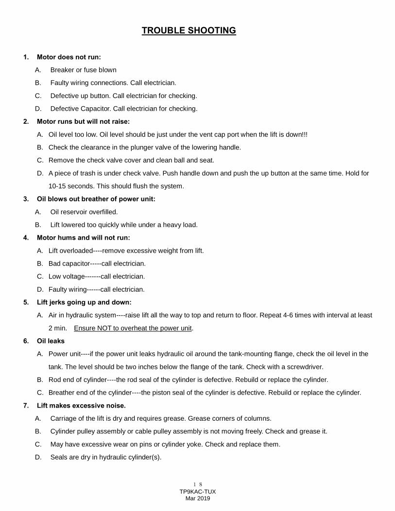
TROUBLE SHOOTING
1. Motor does not run:
A. Breaker or fuse blown
B. Faulty wiring connections. Call electrician.
C. Defective up button. Call electrician for checking.
D. Defective Capacitor. Call electrician for checking.
2. Motor runs but will not raise:
A. Oil level too low. Oil level should be just under the vent cap port when the lift is down!!!
B. Check the clearance in the plunger valve of the lowering handle.
C. Remove the check valve cover and clean ball and seat.
D. A piece of trash is under check valve. Push handle down and push the up button at the same time. Hold for
10-15 seconds. This should flush the system.
3. Oil blows out breather of power unit:
A. Oil reservoir overfilled.
B. Lift lowered too quickly while under a heavy load.
4. Motor hums and will not run:
A. Lift overloaded----remove excessive weight from lift.
B. Bad capacitor-----call electrician.
C. Low voltage-------call electrician.
D. Faulty wiring------call electrician.
5. Lift jerks going up and down:
A. Air in hydraulic system----raise lift all the way to top and return to floor. Repeat 4-6 times with interval at least
2 min. Ensure NOT to overheat the power unit.
6. Oil leaks
A. Power unit----if the power unit leaks hydraulic oil around the tank-mounting flange, check the oil level in the
tank. The level should be two inches below the flange of the tank. Check with a screwdriver.
B. Rod end of cylinder----the rod seal of the cylinder is defective. Rebuild or replace the cylinder.
C. Breather end of the cylinder----the piston seal of the cylinder is defective. Rebuild or replace the cylinder.
7. Lift makes excessive noise.
A. Carriage of the lift is dry and requires grease. Grease corners of columns.
B. Cylinder pulley assembly or cable pulley assembly is not moving freely. Check and grease it.
C. May have excessive wear on pins or cylinder yoke. Check and replace them.
D. Seals are dry in hydraulic cylinder(s).
19 TP9KAC-TUX
Mar 2019
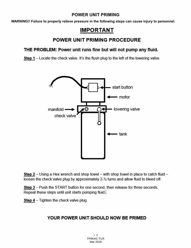
POWER UNIT PRIMING WARNING!! Failure to properly relieve pressure in the following steps can cause injury to personnel.
20 TP9KAC-TUX
Mar 2019
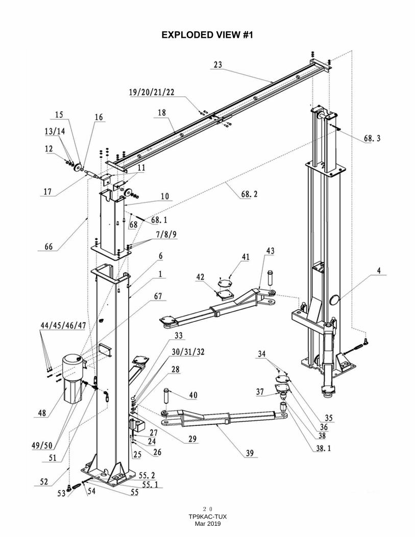
EXPLODED VIEW #1
21 TP9KAC-TUX
Mar 2019
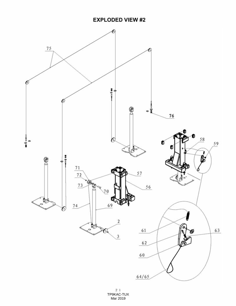
EXPLODED VIEW #2
22 TP9KAC-TUX
Mar 2019
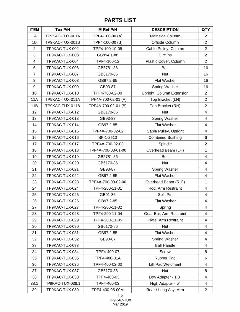
PARTS LIST ITEM Tux P/N M-Ref P/N DESCRIPTION QTY
1A TP9KAC-TUX-001A TPF4-100-00 (A) Mainside Column 2 1B TP9KAC-TUX-001B TPF4-100-00 (B) Offside Column 2 2 TP9KAC-TUX-002 TPF4-100-10-05 Cable Pulley, Column 2 3 TP9KAC-TUX-003 GB894.1-86 Circlips 2 4 TP9KAC-TUX-004 TPF4-100-12 Plastic Cover, Column 2 6 TP9KAC-TUX-006 GB5781-86 Bolt 16 7 TP9KAC-TUX-007 GB6170-86 Nut 16 8 TP9KAC-TUX-008 GB97.2-85 Flat Washer 16 9 TP9KAC-TUX-009 GB93-87 Spring Washer 16 10 TP9KAC-TUX-010 TPF4-700-02-00 Upright, Column Extension 2
11A TP9KAC-TUX-011A TPF4A-700-02-01 (A) Top Bracket (LH) 2 11B TP9KAC-TUX-011B TPF4A-700-02-01 (B) Top Bracket (RH) 2 12 TP9KAC-TUX-012 GB6170-86 Nut 4 13 TP9KAC-TUX-013 GB93-87 Spring Washer 4 14 TP9KAC-TUX-014 GB97.2-85 Flat Washer 4 15 TP9KAC-TUX-015 TPF4A-700-02-02 Cable Pulley, Upright 4 16 TP9KAC-TUX-016 SF-1-2510 Combined Bushing 6 17 TP9KAC-TUX-017 TPF4A-700-02-03 Spindle 2 18 TP9KAC-TUX-018 TPF4A-700-03-01-00 Overhead Beam (LH) 1 19 TP9KAC-TUX-019 GB5781-86 Bolt 4 20 TP9KAC-TUX-020 GB6170-86 Nut 4 21 TP9KAC-TUX-021 GB93-87 Spring Washer 4 22 TP9KAC-TUX-022 GB97.2-85 Flat Washer 4 23 TP9KAC-TUX-023 TPF4A-700-03-02-00 Overhead Beam (RH)) 1 24 TP9KAC-TUX-024 TPF4-200-11-01 Rod, Arm Restraint 4 25 TP9KAC-TUX-025 GB91-86 Split Pin 4 26 TP9KAC-TUX-026 GB97.2-85 Flat Washer 4 27 TP9KAC-TUX-027 TPF4-200-11-02 Spring 4 28 TP9KAC-TUX-028 TPF4-200-11-04 Gear Bar, Arm Restraint 4 29 TP9KAC-TUX-029 TPF4-200-11-05 Plate, Arm Restraint 4 30 TP9KAC-TUX-030 GB6170-86 Nut 4 31 TP9KAC-TUX-031 GB97.2-85 Flat Washer 4 32 TP9KAC-TUX-032 GB93-87 Spring Washer 4 33 TP9KAC-TUX-033 Ball Handle 4 34 TP9KAC-TUX-034 TPF4-400-07 Screw 8 35 TP9KAC-TUX-035 TPF4-400-01A Rubber Pad 6 36 TP9KAC-TUX-036 TPF4-400-02-00 Lift Pad Weldment 4 37 TP9KAC-TUX-037 GB6170-86 Nut 8 38 TP9KAC-TUX-038 TPF4-400-03 Low Adapter - 1.3" 4
38.1 TP9KAC-TUX-038.1 TPF4-400-03 High Adapter - 5" 4 39 TP9KAC-TUX-039 TPF4-400-05-00M Rear / Long Asy, Arm 2
23 TP9KAC-TUX
Mar 2019
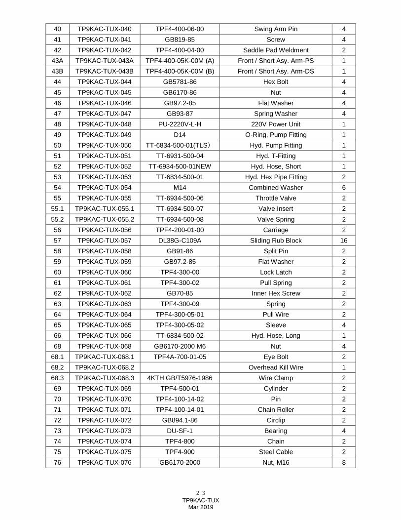
40 TP9KAC-TUX-040 TPF4-400-06-00 Swing Arm Pin 4 41 TP9KAC-TUX-041 GB819-85 Screw 4 42 TP9KAC-TUX-042 TPF4-400-04-00 Saddle Pad Weldment 2
43A TP9KAC-TUX-043A TPF4-400-05K-00M (A) Front / Short Asy. Arm-PS 1 43B TP9KAC-TUX-043B TPF4-400-05K-00M (B) Front / Short Asy. Arm-DS 1 44 TP9KAC-TUX-044 GB5781-86 Hex Bolt 4 45 TP9KAC-TUX-045 GB6170-86 Nut 4 46 TP9KAC-TUX-046 GB97.2-85 Flat Washer 4 47 TP9KAC-TUX-047 GB93-87 Spring Washer 4 48 TP9KAC-TUX-048 PU-2220V-L-H 220V Power Unit 1 49 TP9KAC-TUX-049 D14 O-Ring, Pump Fitting 1 50 TP9KAC-TUX-050 TT-6834-500-01(TLS) Hyd. Pump Fitting 1 51 TP9KAC-TUX-051 TT-6931-500-04 Hyd. T-Fitting 1 52 TP9KAC-TUX-052 TT-6934-500-01NEW Hyd. Hose, Short 1 53 TP9KAC-TUX-053 TT-6834-500-01 Hyd. Hex Pipe Fitting 2 54 TP9KAC-TUX-054 M14 Combined Washer 6 55 TP9KAC-TUX-055 TT-6934-500-06 Throttle Valve 2
55.1 TP9KAC-TUX-055.1 TT-6934-500-07 Valve Insert 2 55.2 TP9KAC-TUX-055.2 TT-6934-500-08 Valve Spring 2 56 TP9KAC-TUX-056 TPF4-200-01-00 Carriage 2 57 TP9KAC-TUX-057 DL38G-C109A Sliding Rub Block 16 58 TP9KAC-TUX-058 GB91-86 Split Pin 2 59 TP9KAC-TUX-059 GB97.2-85 Flat Washer 2 60 TP9KAC-TUX-060 TPF4-300-00 Lock Latch 2 61 TP9KAC-TUX-061 TPF4-300-02 Pull Spring 2 62 TP9KAC-TUX-062 GB70-85 Inner Hex Screw 2 63 TP9KAC-TUX-063 TPF4-300-09 Spring 2 64 TP9KAC-TUX-064 TPF4-300-05-01 Pull Wire 2 65 TP9KAC-TUX-065 TPF4-300-05-02 Sleeve 4 66 TP9KAC-TUX-066 TT-6834-500-02 Hyd. Hose, Long 1 68 TP9KAC-TUX-068 GB6170-2000 M6 Nut 4
68.1 TP9KAC-TUX-068.1 TPF4A-700-01-05 Eye Bolt 2 68.2 TP9KAC-TUX-068.2 Overhead Kill Wire 1 68.3 TP9KAC-TUX-068.3 4KTH GB/T5976-1986 Wire Clamp 2 69 TP9KAC-TUX-069 TPF4-500-01 Cylinder 2 70 TP9KAC-TUX-070 TPF4-100-14-02 Pin 2 71 TP9KAC-TUX-071 TPF4-100-14-01 Chain Roller 2 72 TP9KAC-TUX-072 GB894.1-86 Circlip 2 73 TP9KAC-TUX-073 DU-SF-1 Bearing 4 74 TP9KAC-TUX-074 TPF4-800 Chain 2 75 TP9KAC-TUX-075 TPF4-900 Steel Cable 2 76 TP9KAC-TUX-076 GB6170-2000 Nut, M16 8
24 TP9KAC-TUX
Mar 2019
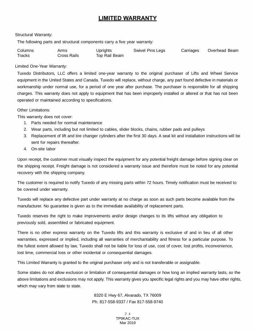
LIMITED WARRANTY Structural Warranty: The following parts and structural components carry a five year warranty:
Columns Arms Uprights Swivel Pins Legs Carriages Overhead Beam Tracks Cross Rails Top Rail Beam
Limited One-Year Warranty: Tuxedo Distributors, LLC offers a limited one-year warranty to the original purchaser of Lifts and Wheel Service equipment in the United States and Canada. Tuxedo will replace, without charge, any part found defective in materials or workmanship under normal use, for a period of one year after purchase. The purchaser is responsible for all shipping charges. This warranty does not apply to equipment that has been improperly installed or altered or that has not been operated or maintained according to specifications.
Other Limitations: This warranty does not cover:
1. Parts needed for normal maintenance 2. Wear parts, including but not limited to cables, slider blocks, chains, rubber pads and pulleys 3. Replacement of lift and tire changer cylinders after the first 30 days. A seal kit and installation instructions will be
sent for repairs thereafter. 4. On-site labor
Upon receipt, the customer must visually inspect the equipment for any potential freight damage before signing clear on the shipping receipt. Freight damage is not considered a warranty issue and therefore must be noted for any potential recovery with the shipping company.
The customer is required to notify Tuxedo of any missing parts within 72 hours. Timely notification must be received to be covered under warranty.
Tuxedo will replace any defective part under warranty at no charge as soon as such parts become available from the manufacturer. No guarantee is given as to the immediate availability of replacement parts.
Tuxedo reserves the right to make improvements and/or design changes to its lifts without any obligation to previously sold, assembled or fabricated equipment.
There is no other express warranty on the Tuxedo lifts and this warranty is exclusive of and in lieu of all other warranties, expressed or implied, including all warranties of merchantability and fitness for a particular purpose. To the fullest extent allowed by law, Tuxedo shall not be liable for loss of use, cost of cover, lost profits, inconvenience, lost time, commercial loss or other incidental or consequential damages.
This Limited Warranty is granted to the original purchaser only and is not transferable or assignable.
Some states do not allow exclusion or limitation of consequential damages or how long an implied warranty lasts, so the above limitations and exclusions may not apply. This warranty gives you specific legal rights and you may have other rights, which may vary from state to state.
8320 E Hwy 67, Alvarado, TX 76009 Ph. 817-558-9337 / Fax 817-558-9740