tp 2. the aircraft · leading exporter of advanced technology and is the fourth largest producer of...
TRANSCRIPT

A-CR-CCP-804/PF-001
C470.01-1
ROYAL CANADIAN AIR CADETS
PROFICIENCY LEVEL FOUR
INSTRUCTIONAL GUIDE
SECTION 1
EO C470.01 – DISCUSS AIRCRAFT MANUFACTURERS
Total Time: 30 min
PREPARATION
PRE-LESSON INSTRUCTIONS
Resources needed for the delivery of this lesson are listed in the lesson specification located in A-CR-CCP-804/PG-001, Proficiency Level Four Qualification Standard and Plan, Chapter 4. Specific uses for said resourcesare identified throughout the instructional guide within the TP for which they are required.
Review the lesson content and become familiar with the material prior to delivering the lesson.
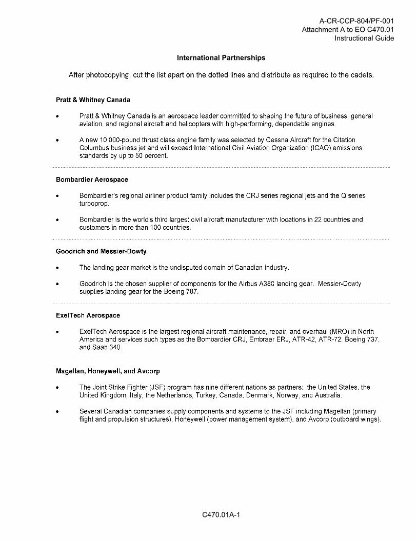
Prepare the list of international partnerships located at Attachment A by photocopying the list and cutting thesections apart to distribute to the cadets.
Photocopy the International Partnership Summary Sheet located at Attachment B for each cadet.
Photocopy the Unmanned Aerial Vehicle (UAV) Manufacturers Worksheet located at Attachment C for eachcadet.
UAVs are continuously changing. The information presented in Reference C3-324 may be used as a startingpoint in researching current UAVs and UAV manufacturers. Research current UAVs and UAV manufacturersand collect information on two or three UAVs from newspapers, magazines, journals or websites to present inTP 2. The Aircraft page on the Air Force website (http://www.airforce.gc.ca) may include information on UAVsused by the Canadian Forces.
PRE-LESSON ASSIGNMENT
At least one week before the lesson, assign each cadet (or have each cadet select) an international partnershipfrom the list of international partnerships located at Attachment A. Distribute an International PartnershipSummary Sheet located at Attachment B to each cadet. Have the cadets review and research the internationalpartnership details and prepare a short oral presentation (approximately 2–5 minutes) using the InternationalPartnership Summary Sheet located at Attachment B.
APPROACH
An in-class activity was chosen for TP 1 as it is an interactive way to provoke thought and stimulate interestamong cadets.
An interactive lecture was chosen for TP 2 to identify UAV manufacturers.
A-CR-CCP-804/PF-001
C470.01-2
INTRODUCTION
REVIEW
Nil.
OBJECTIVES
By the end of this lesson the cadet shall have discussed international partnerships between aircraftmanufacturers and identified UAV manufacturers.
IMPORTANCE
It is important for cadets to discuss international partnerships between aircraft manufacturers as Canada is aleading exporter of advanced technology and is the fourth largest producer of civil aircraft in the world. It isimportant for cadets to identify UAV manufacturers as UAVs are a relatively new technology and are rapidlybecoming more important in aviation, especially military aviation.

A-CR-CCP-804/PF-001
C470.01-3
Teaching Point 1 Conduct an activity where the cadets will review asummary of an international partnership between aircraftmanufacturers and make a short oral presentation on the
international partnership.
Time: 20 min Method: In-Class Activity
ACTIVITY
OBJECTIVE
The objective of this activity is have the cadets review a summary of an international partnership betweenaircraft manufacturers and make a short oral presentation on the international partnership.
RESOURCES
Pen / pencil,
List of international partnerships located at Attachment A, and
International Partnership Summary Sheet located at Attachment B.
ACTIVITY LAYOUT
Nil.
ACTIVITY INSTRUCTIONS
Have each cadet make a short oral presentation (approximately 2–5 minutes) to the group on their selected /assigned international partnership using the information they have recorded on the International PartnershipSummary Sheet.
If there is not enough time for all the cadets to make their presentations, the cadets can bedivided into two or more groups.
SAFETY
Nil.
CONFIRMATION OF TEACHING POINT 1
The cadets' participation in the activity will serve as the confirmation of this TP.
A-CR-CCP-804/PF-001
C470.01-4
Teaching Point 2 Identify UAV manufacturers.
Time: 5 min Method: Interactive Lecture
Distribute an Unmanned Aerial Vehicles (UAV) Manufacturers Worksheet located atAttachment C to each cadet.
Present the information collected on the UAVs to the cadets and have the cadets makenotes using the Unmanned Aerial Vehicles (UAV) Manufacturers Worksheet.
CONFIRMATION OF TEACHING POINT 2
The cadets' completion of the Unmanned Aerial Vehicles (UAV) Manufacturers Worksheet will serve as theconfirmation of this TP.
END OF LESSON CONFIRMATION
The cadets' participation in presenting the information on an international manufacturing partnership will serveas the confirmation of this lesson.
CONCLUSION
HOMEWORK / READING / PRACTICE
Nil.
METHOD OF EVALUATION
Nil.
CLOSING STATEMENT
Canada is one of the world's leading suppliers of aviation technology. International partnerships betweenCanadian aviation manufacturers and those in other countries results in 85 percent of the aviation productionbeing sold internationally. The use of UAVs, especially in military aviation, is growing rapidly and themanufacturing of UAVs is becoming an important sector in aviation manufacturing.
INSTRUCTOR NOTES / REMARKS
Cadets who are qualified Advanced Aviation Technology – Aircraft Manufacturing and Maintenance may beable to assist with this lesson.

A-CR-CCP-804/PF-001
C470.01-5
REFERENCES
C3-321 ISBN 978-2-921393-91-1 Bombardier Inc. (2009). Canada's Bombardier. Canada: Bombardier Inc.
C3-322 Government of Canada. (2008). Canada's aerospace advantages. Retrieved February 10,2009 from http://investincanada.gc.ca/eng/industry-sectors/advanced-manufacturing/aerospace/aerospace-advantages.aspx
C3-323 Industry Canada. (2009). Aerospace in Canada. Retrieved February 10, 2009 from http://www.ic.gc.ca/eic/site/ad-ad.nsf/eng/ad03909.html
C3-324 Thirty Thousand Feet Aviation Directory. (2009). Unmanned aerial vehicles. Retrieved February 10,2009, from http://www.thirtythousandfeet.com/uav.htm

A-CR-CCP-804/PF-001
THIS PAGE INTENTIONALLY LEFT BLANK
C470.01-6
A-CR-CCP-804/PF-001Attachment A to EO C470.01
Instructional Guide
C470.01A-1
International Partnerships

A-CR-CCP-804/PF-001Attachment A to EO C470.01Instructional Guide
C470.01A-2

A-CR-CCP-804/PF-001Attachment B to EO C470.01
Instructional Guide
C470.01B-1
International Partnership Summary Sheet
Companies and Countries Involved
Aircraft Types and / or Components Involved
Additional Information

A-CR-CCP-804/PF-001Attachment B to EO C470.01Instructional Guide
THIS PAGE INTENTIONALLY LEFT BLANK
C470.01B-2
A-CR-CCP-804/PF-001Attachment C to EO C470.01
Instructional Guide
C470.01C-1
Unmanned Aerial Vehicle (UAV) Manufacturers Worksheet

A-CR-CCP-804/PF-001Attachment C to EO C470.01Instructional Guide
THIS PAGE INTENTIONALLY LEFT BLANK
C470.01C-2
A-CR-CCP-804/PF-001
C470.02-1
ROYAL CANADIAN AIR CADETS
PROFICIENCY LEVEL FOUR
INSTRUCTIONAL GUIDE
SECTION 2
EO C470.02 – DISCUSS AIRCRAFT ASSEMBLY
Total Time: 30 min
PREPARATION
PRE-LESSON INSTRUCTIONS
Resources needed for the delivery of this lesson are listed in the lesson specification located in A-CR-CCP-804/PG-001, Proficiency Level Four Qualification Standard and Plan, Chapter 4. Specific uses for said resourcesare identified throughout the instructional guide within the TP for which they are required.
Review the lesson content and become familiar with the material prior to delivering the lesson.
Create slides of the Figures located at Attachments A and B.
Cue The World's Biggest Airliner: The Airbus A380 DVD to the first chapter, Toulouse, France (seven minutes).
PRE-LESSON ASSIGNMENT
Nil.
APPROACH
An interactive lecture was chosen for this lesson to introduce aspects of aircraft assembly methods and givean overview of them.
INTRODUCTION
REVIEW
Nil.
OBJECTIVES
By the end of this lesson the cadet shall have discussed the assembly of aircraft components in a manufacturingsetting.
IMPORTANCE
It is important for the cadets to learn about aircraft assembly methods because this will enhance theirunderstanding of aircraft and the field of aviation.
A-CR-CCP-804/PF-001
C470.02-2
Teaching Point 1 Describe different methods of assembly of components.
Time: 15 min Method: Interactive Lecture
SMALL MANUFACTURERS
For an aircraft to fly correctly, the main structural components, such as fuselage, wings, engines andempennage parts must be aligned perfectly. Any deviation or flaw, such as a twist in any component, will impairflight and have a negative effect on flight controls. Cranes hold the heavy parts in place, jigs and templatesposition them precisely. The development of techniques for measuring and positioning components on thestructure to a high degree of accuracy have been developed, as aircraft have become heavier and faster.
LARGE MANUFACTURERS
Some aircraft are now so large that cranes cannot lift and hold the parts satisfactorily. Special carriers arecustom-built to hold the parts, while computer control is used to bring them together. Lasers measure distancesand angles with the use of mirrors, and send the data to high-speed computers. By using these methods, thefuselage, wings and empennage components can be assembled precisely, no matter how large they are.
Not all aircraft components are structural. A company such as Bombardier Aerospace has hundreds of suppliersthat provide everything from horizontal stabilizers to airspeed indicators. All of these components fit and worktogether as a result of a process called Systems Integration. The aerospace engineers designing the aircraftmust ensure that physical components and associated software programs work together.
Show the cadets the first chapter Toulouse France of The World's Biggest Airliner: TheAirbus A380. This section covers the use of mirrors and an infrared laser positioning systemand shows the fuselage components being joined.
CONFIRMATION OF TEACHING POINT 1
QUESTIONS:
Q1. Why must an aircraft's structural components be aligned perfectly?
Q2. For large aircraft, what type of control is used to bring the structural parts together?
Q3. What is the name of the process that aeronautical engineers use to integrate separate systems?
ANTICIPATED ANSWERS:
A1. Any deviation or flaw will impair flight and have a negative effect on flight controls.
A2. Computer control.
A3. Systems Integration.

A-CR-CCP-804/PF-001
C470.02-3
Teaching Point 2 Discuss manufacturers' assembly areas.
Time: 10 min Method: Interactive Lecture
A SMALL MANUFACTURER'S SHOP
Small manufacturers can often perform all necessary operations in one location like Viking Air, whichmanufactures the new 400 series Twin Otter and remanufactures Beaver and Otter aircraft near the VictoriaInternational Airport in Sydney, British Columbia. A small manufacturer's shop is characterized by all the aircraftparts and materials coming together at one manufacturing plant prior to final assembly. All necessary machineryand facilities are provided, sometimes under one roof. Manufacturing encompasses all phases of assemblyfrom sheet metal bending, engine assembly, avionics and final painting and interior finish.
Viking Air is considered a small manufacturer's shop. They manufacture, assemble, modify,and repair aircraft.
A LARGE MANUFACTURER'S ASSEMBLY LINE
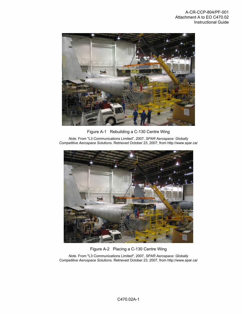
All manufacturers need machines to move large, heavy components such as wings and to control their motionwith precision. In the assembly areas of large aircraft, these machines are also large.
Show the cadets the series of assembly area photographs located at Attachment A.
Larger manufacturers generally have more career specialization than smaller ones, such asengine, airframe or avionics specialization. Small manufacturers have fewer employees, sothey need their employees to be able to handle more related fields.
Large manufacturers such as Bombardier Aerospace have facilities around the world. The materials andcomponents for the basic aircraft structure are gathered at one assembly plant, such as Downsview in Toronto,Ontario. This plant is responsible for the final assembly of structural components for the Learjet 45 aircraft, theQ-Series turboprops and the Global family of business aircraft. The facility occupies 324 acres of land and hasalmost two million square feet of building floor space. At Dorval, Quebec, Bombardier has a completion facilitywith 31 345 square metres (337 400 square feet), housing up to 14 Global Express aircraft and a delivery centrein which customers can choose design options in a virtual reality environment. The finishing touches, such ascabin furnishings, are installed here. A separate 7 246 square metre (78 000 square foot) paint and strip shopis located next to the completion centre, capable of housing up to four aircraft at a time.
Another 38 591 square metre (415 400 square foot) facility is located in Dorval, near the Bombardier Aerospaceadministrative centre and the Canadair aircraft assembly plant.
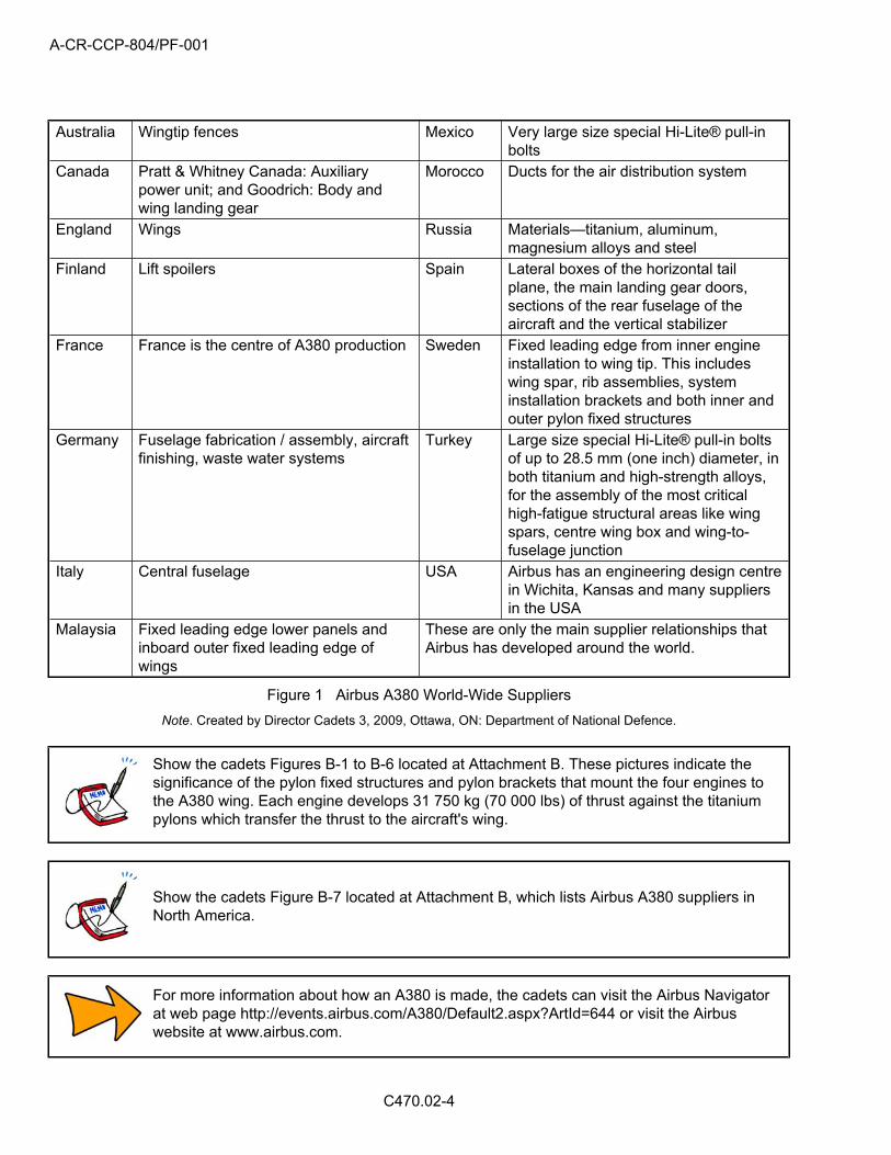
Airbus has an even larger operation. The A380 is assembled and delivered in Europe and has major structuralcomponents made in Australia, Canada, England, Finland, France, Germany, Italy, Malaysia, Mexico, Morocco,Russia, Spain, Turkey and the USA.
Suppliers, for both structural and minor components, are located around the world:
A-CR-CCP-804/PF-001
C470.02-4
Australia Wingtip fences Mexico Very large size special Hi-Lite® pull-inbolts
Canada Pratt & Whitney Canada: Auxiliarypower unit; and Goodrich: Body andwing landing gear
Morocco Ducts for the air distribution system
England Wings Russia Materials—titanium, aluminum,magnesium alloys and steel
Finland Lift spoilers Spain Lateral boxes of the horizontal tailplane, the main landing gear doors,sections of the rear fuselage of theaircraft and the vertical stabilizer
France France is the centre of A380 production Sweden Fixed leading edge from inner engineinstallation to wing tip. This includeswing spar, rib assemblies, systeminstallation brackets and both inner andouter pylon fixed structures
Germany Fuselage fabrication / assembly, aircraftfinishing, waste water systems
Turkey Large size special Hi-Lite® pull-in boltsof up to 28.5 mm (one inch) diameter, inboth titanium and high-strength alloys,for the assembly of the most criticalhigh-fatigue structural areas like wingspars, centre wing box and wing-to-fuselage junction
Italy Central fuselage USA Airbus has an engineering design centrein Wichita, Kansas and many suppliersin the USA
Malaysia Fixed leading edge lower panels andinboard outer fixed leading edge ofwings
These are only the main supplier relationships thatAirbus has developed around the world.
Figure 1 Airbus A380 World-Wide Suppliers
Note. Created by Director Cadets 3, 2009, Ottawa, ON: Department of National Defence.
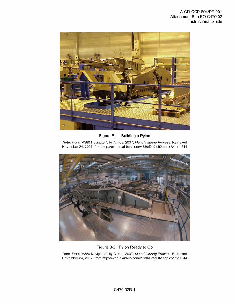
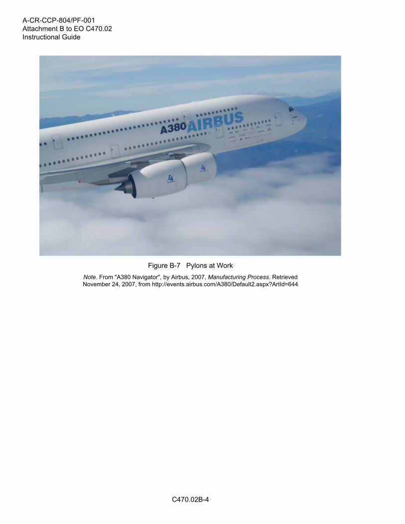
Show the cadets Figures B-1 to B-6 located at Attachment B. These pictures indicate thesignificance of the pylon fixed structures and pylon brackets that mount the four engines tothe A380 wing. Each engine develops 31 750 kg (70 000 lbs) of thrust against the titaniumpylons which transfer the thrust to the aircraft's wing.
Show the cadets Figure B-7 located at Attachment B, which lists Airbus A380 suppliers inNorth America.
For more information about how an A380 is made, the cadets can visit the Airbus Navigatorat web page http://events.airbus.com/A380/Default2.aspx?ArtId=644 or visit the Airbuswebsite at www.airbus.com.

A-CR-CCP-804/PF-001
C470.02-5
CONFIRMATION OF TEACHING POINT 2
QUESTIONS:
Q1. What characterizes a small manufacturer's shop?
Q2. Where are large manufacturers located?
Q3. What happens at a large manufacturer's completion facility?
ANTICIPATED ANSWERS:
A1. All the aircraft parts and materials come together at one place prior to final assembly.
A2. Around the world.
A3. The finishing touches, such as cabin furnishings, are installed.
END OF LESSON CONFIRMATION
QUESTIONS:
Q1. Why must an aircraft's structural components be aligned perfectly?
Q2. What happens at a large manufacturer's completion facility?
Q3. What is different with respect to career specialization between large and small manufacturers?
ANTICIPATED ANSWERS:
A1. Any deviation or flaw will impair flight and have a negative effect upon flight controls.
A2. The finishing touches, such as cabin furnishings, are installed.
A3. Larger manufacturers generally have more career specialization than smaller ones.
CONCLUSION
HOMEWORK / READING / PRACTICE
Nil.
METHOD OF EVALUATION
Nil.
CLOSING STATEMENT
Precise assembly of large structures is a difficult yet critically important aspect of aircraft manufacturing, whichbenefits from continued development and improved techniques.
INSTRUCTOR NOTES / REMARKS
The cadets may have previously viewed The World's Biggest Airliner: The Airbus A380 if EO C270.04 wasselected in Proficiency Level Two. This lesson focuses and expands on the assembly of aircraft.
Cadets who are qualified Advanced Aviation Technology – Aircraft Manufacturing and Maintenance may beable to assist with this lesson.

A-CR-CCP-804/PF-001
C470.02-6
REFERENCES
C3-105 Brisley, T., & Pascaud, S. (Executive Producer), & Bowie, B. (Writer / Director) (2003). World’s biggestairliner: The Airbus A380 [Motion Picture]. United States: The Learning Channel.
C3-136 ISBN 0-88487-207-6 Sanderson Training Systems. (2001). A&P technician airframe textbook.Englewood, CO: Jeppesen Sanderson Inc.
A-CR-CCP-804/PF-001Attachment A to EO C470.02
Instructional Guide
C470.02A-1
Figure A-1 Rebuilding a C-130 Centre Wing
Note. From "L3 Communications Limited", 2007, SPAR Aerospace: GloballyCompetitive Aerospace Solutions. Retrieved October 23, 2007, from http://www.spar.ca/
Figure A-2 Placing a C-130 Centre Wing
Note. From "L3 Communications Limited", 2007, SPAR Aerospace: GloballyCompetitive Aerospace Solutions. Retrieved October 23, 2007, from http://www.spar.ca/
A-CR-CCP-804/PF-001Attachment A to EO C470.02Instructional Guide
C470.02A-2
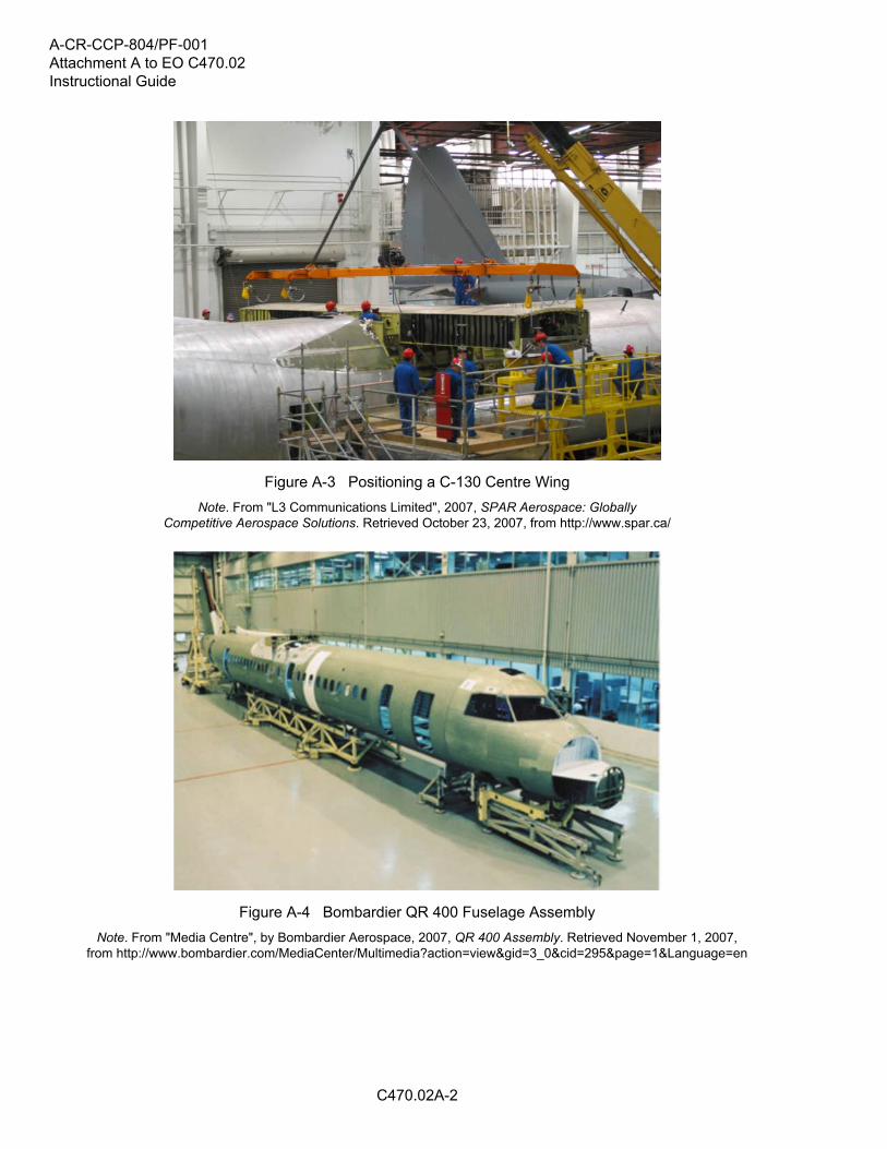
Figure A-3 Positioning a C-130 Centre Wing
Note. From "L3 Communications Limited", 2007, SPAR Aerospace: GloballyCompetitive Aerospace Solutions. Retrieved October 23, 2007, from http://www.spar.ca/
Figure A-4 Bombardier QR 400 Fuselage Assembly
Note. From "Media Centre", by Bombardier Aerospace, 2007, QR 400 Assembly. Retrieved November 1, 2007,from http://www.bombardier.com/MediaCenter/Multimedia?action=view&gid=3_0&cid=295&page=1&Language=en

A-CR-CCP-804/PF-001Attachment A to EO C470.02
Instructional Guide
C470.02A-3
Figure A-5 Bombardier QR 400 Wing Assembly
Note. From "Media Centre", by Bombardier Aerospace, 2007, QR 400 Assembly. Retrieved November 1, 2007,from http://www.bombardier.com/MediaCenter/Multimedia?action=view&gid=3_0&cid=295&page=1&Language=en
Figure A-6 Bombardier QR 400 Assembly Line
Note. From "Media Centre", by Bombardier Aerospace, 2007, QR 400 Assembly. Retrieved November 1, 2007,from http://www.bombardier.com/MediaCenter/Multimedia?action=view&gid=3_0&cid=295&page=1&Language=en

A-CR-CCP-804/PF-001Attachment A to EO C470.02Instructional Guide
C470.02A-4
Figure A-7 Bombardier QR 400 Assembly Activity
Note. From "Media Centre", by Bombardier Aerospace, 2007, QR 400 Assembly. Retrieved November 1, 2007,from http://www.bombardier.com/MediaCenter/Multimedia?action=view&gid=3_0&cid=295&page=1&Language=en
Figure A-8 Bombardier QR 400 Engine Assembly
Note. From "Media Centre", by Bombardier Aerospace, 2007, QR 400 Assembly. Retrieved November 1, 2007,from http://www.bombardier.com/MediaCenter/Multimedia?action=view&gid=3_0&cid=295&page=1&Language=en

A-CR-CCP-804/PF-001Attachment A to EO C470.02
Instructional Guide
C470.02A-5
Figure A-9 Bombardier CRJ700 Fuselage Assembly
Note. From "Media Centre", by Bombardier Aerospace, 2007,CRJ700 Assembly. Retrieved November 1, 2007,from http://www.bombardier.com/MediaCenter/Multimedia?action=view&gid=3_0&cid=295&page=1&Language=en
Figure A-10 Bombardier CRJ700 Assembly Line
Note. From "Media Centre", by Bombardier Aerospace, 2007,CRJ700 Assembly. Retrieved November 1, 2007,from http://www.bombardier.com/MediaCenter/Multimedia?action=view&gid=3_0&cid=295&page=1&Language=en
A-CR-CCP-804/PF-001Attachment A to EO C470.02Instructional Guide
C470.02A-6
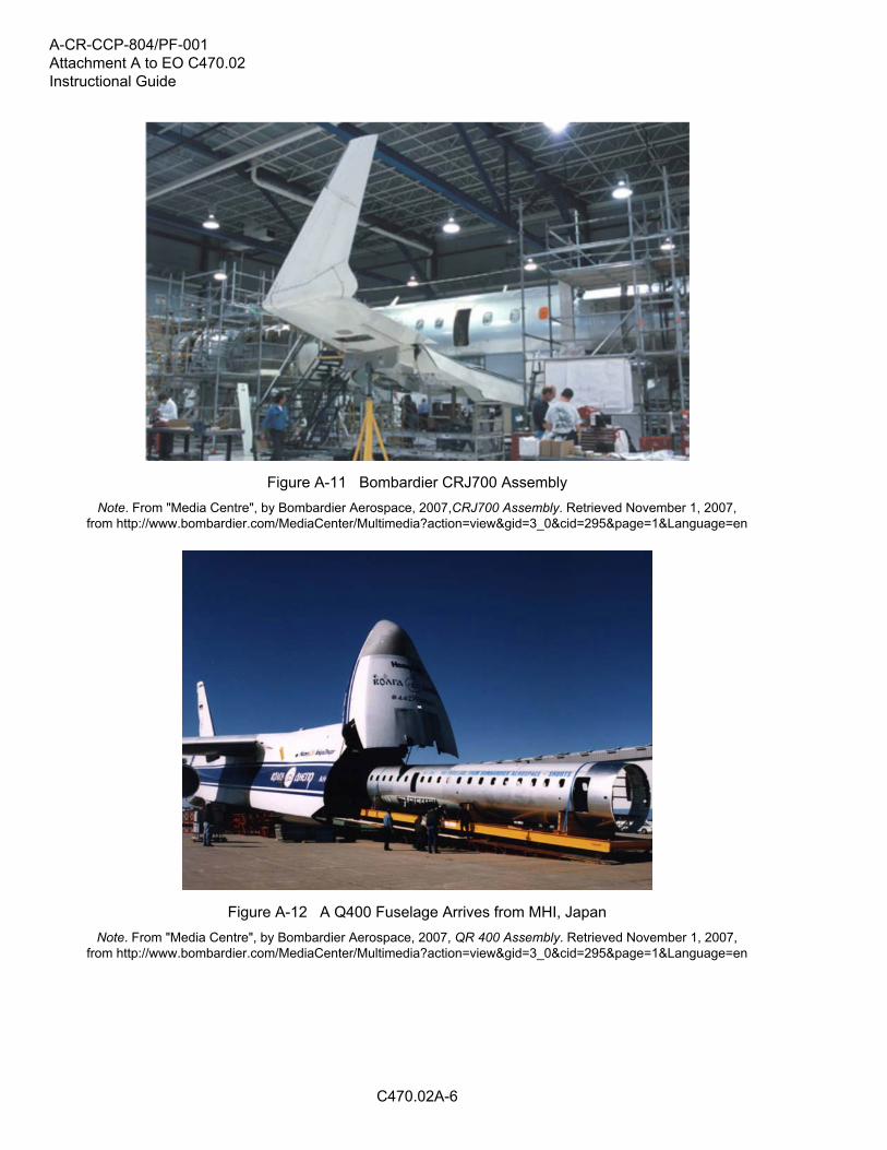
Figure A-11 Bombardier CRJ700 Assembly
Note. From "Media Centre", by Bombardier Aerospace, 2007,CRJ700 Assembly. Retrieved November 1, 2007,from http://www.bombardier.com/MediaCenter/Multimedia?action=view&gid=3_0&cid=295&page=1&Language=en
Figure A-12 A Q400 Fuselage Arrives from MHI, Japan
Note. From "Media Centre", by Bombardier Aerospace, 2007, QR 400 Assembly. Retrieved November 1, 2007,from http://www.bombardier.com/MediaCenter/Multimedia?action=view&gid=3_0&cid=295&page=1&Language=en
A-CR-CCP-804/PF-001Attachment B to EO C470.02
Instructional Guide
C470.02B-1
Figure B-1 Building a Pylon
Note. From "A380 Navigator", by Airbus, 2007, Manufacturing Process. RetrievedNovember 24, 2007, from http://events.airbus.com/A380/Default2.aspx?ArtId=644
Figure B-2 Pylon Ready to Go
Note. From "A380 Navigator", by Airbus, 2007, Manufacturing Process. RetrievedNovember 24, 2007, from http://events.airbus.com/A380/Default2.aspx?ArtId=644

A-CR-CCP-804/PF-001Attachment B to EO C470.02Instructional Guide
C470.02B-2
Figure B-3 Pylon on Display
Note. From "A380 Navigator", by Airbus, 2007, Manufacturing Process. RetrievedNovember 24, 2007, from http://events.airbus.com/A380/Default2.aspx?ArtId=644
Figure B-4 Empty Pylons
Note. From "A380 Navigator", by Airbus, 2007, Manufacturing Process. RetrievedNovember 24, 2007, from http://events.airbus.com/A380/Default2.aspx?ArtId=644

A-CR-CCP-804/PF-001Attachment B to EO C470.02
Instructional Guide
C470.02B-3
Figure B-5 Engines on Pylons
Note. From "A380 Navigator", by Airbus, 2007, Manufacturing Process. RetrievedNovember 24, 2007, from http://events.airbus.com/A380/Default2.aspx?ArtId=644
Figure B-6 A380 with Engines
Note. From "A380 Navigator", by Airbus, 2007, Manufacturing Process. RetrievedNovember 24, 2007, from http://events.airbus.com/A380/Default2.aspx?ArtId=644
A-CR-CCP-804/PF-001Attachment B to EO C470.02Instructional Guide
C470.02B-4
Figure B-7 Pylons at Work
Note. From "A380 Navigator", by Airbus, 2007, Manufacturing Process. RetrievedNovember 24, 2007, from http://events.airbus.com/A380/Default2.aspx?ArtId=644

A-CR-CCP-804/PF-001Attachment B to EO C470.02
Instructional Guide
C470.02B-5
L-3 COMMUNICATIONS AVIATIONRECORDERS L-3 Communications Aviation Recorders (L-3AR)provides the flight data recorder and cockpit voicerecorder for the A380. ROCKWELL COLLINS Rockwell Collins’ suite of communication andnavigation sensors provides the baseline for theA380. ALCOA Alcoa supplies forgings, extrusions, sheet, plate,and castings for the A380’s wing and fuselageskins, stringers, frames, spars, gear ribs, engineand pylon support, seat tracks and floor beams. C&D AEROSPACE California-based C&D Aerospace provides aircraftinterior systems for the A380. CYTEC - ENGINEERED MATERIALS Cytec Engineered Materials producescomposites, adhesives and carbon fibres. EATON CORPORATION US-based Eaton Corporation supplies the A380with a highly-advanced higher-pressure hydraulicfluid power generation system, the world’s first5000-psi pump for a commercial aircraft. HONEYWELL AEROSPACE Honeywell Aerospace will deliver 12 products andsystems for the A380.
M.C.GILL CORPORATION M.C. Gill Corporation provides fully equippedcomposite floor panels for the cockpit of theA380, the main electronics bay situated below thecockpit and the emergency electronics bay, whichsits forward of the upper deck passenger cabin. MEGGITT SAFETY SYSTEMS Meggitt Safety Systems Inc.(MSSI) supplies thefire detection systems for the A380’s engines,auxiliary power units (APUs) and main landinggears. MONOGRAM SYSTEMS Monogram Systems, a unit of Zodiac’s airlineequipment branch in California, supplies anadvanced water and vacuum waste system forthe A380 that will incorporate state-of-the-arttechnical innovations. NORTHROP GRUMMAN The navigation systems division of US defencecompany Northrop Grumman supplies the A380with its LTN-101E global navigation air datainertial reference unit. PARKER Parker Aerospace, a business unit of the ParkerHannifin Corporation, is participating in severalwork packages for the A380. RALEE Ralee Engineering Company, a Triumph Groupcompany based in California, supplies the wingtop skin stringers (the metal structure that goesunder the wing panels) for the A380.
Figure B-8 Airbus A380 North American Suppliers
Note. Created by Director Cadets 3, 2007, Ottawa, ON: Department of National Defence.

A-CR-CCP-804/PF-001Attachment B to EO C470.02Instructional Guide
THIS PAGE INTENTIONALLY LEFT BLANK
C470.02B-6
A-CR-CCP-804/PF-001
C470.03-1
ROYAL CANADIAN AIR CADETS
PROFICIENCY LEVEL FOUR
INSTRUCTIONAL GUIDE
SECTION 3
EO C470.03 – IDENTIFY AVIATION HARDWARE
Total Time: 30 min
PREPARATION
PRE-LESSON INSTRUCTIONS
Resources needed for the delivery of this lesson are listed in the lesson specification located in A-CR-CCP-804/PG-001, Proficiency Level Four Qualification Standard and Plan, Chapter 4. Specific uses for said resourcesare identified throughout the instructional guide within the TP for which they are required.
Review the lesson content and become familiar with the material prior to delivering the lesson.
The activity in TP 1 uses learning stations. Learning stations are a form of group work, where the cadets learnby sorting through the information presented. When setting up learning stations, ensure there is enough roomfor each cadet to be comfortable and adequate space for writing down information. When the cadets arrive ata learning station, all required information shall be available. These stations should be placed closely togetherto minimize time for movement; however, far enough apart to avoid interruptions from other groups. For thislesson, set up four learning stations for aviation hardware.
Photocopy the Aviation Hardware Handout located at Attachment A (one per cadet), Aviation HardwareInformation Sheets located at Attachments B–E (one attachment per station), and the Aviation HardwareIdentification Worksheet located at Attachment F (one per cadet).
PRE-LESSON ASSIGNMENT
Nil.
APPROACH
An in-class activity was chosen for this lesson as it is an interactive way to provoke thought and stimulateinterest among cadets.
INTRODUCTION
REVIEW
Nil.
OBJECTIVES
By the end of this lesson the cadet shall have identified aviation hardware.

A-CR-CCP-804/PF-001
C470.03-2
IMPORTANCE
It is important for cadets to be able to identify aviation hardware as each type of hardware has a specificapplication. Using the correct type of aviation hardware during maintenance activities and the manufacturing ofaircraft and aircraft components ensures that the design specifications and safety tolerances are maintained.Using the incorrect type of aviation hardware could jeopardize the safety of the aircrew, passengers, andpersonnel on the ground.
A-CR-CCP-804/PF-001
C470.03-3
Teaching Point 1 Conduct an activity where the cadets will identify aviationhardware.
Time: 25 min Method: In-Class Activity
ACTIVITY
OBJECTIVE
The objective of this activity is to have the cadets identify aviation hardware.
RESOURCES
Pen / pencil,
Aviation Hardware Handout located at Attachment A,
Aviation Hardware Information Sheets located at Attachments B–E,
Aviation Hardware Identification Worksheet located at Attachment F, and
Aviation Hardware Identification Worksheet Answer Key located at Attachment G.
ACTIVITY LAYOUT
If samples of aviation hardware are available, place them at the appropriate learning station.
ACTIVITY INSTRUCTIONS
1. Brief cadets on activity instructions, to include:
a. time limit for each station (five minutes),
b. direction of rotation between stations,
c. signal for rotation,
d. explanation of Aviation Hardware Information Sheets, and
e. an overview of the Aviation Hardware Identification Worksheet.
2. Distribute the Aviation Hardware Identification Worksheet located at Attachment F (to each cadet).
3. Divide the cadets into four groups and assign a number to each group.
4. Have groups move to the learning station which corresponds to their group number.
5. Have the cadets complete the Aviation Hardware Identification Worksheet while rotating from station tostation every five minutes.
A-CR-CCP-804/PF-001
C470.03-4
It is important to circulate around the room to facilitate the activities and help the cadets asrequired. If possible, assign other instructors to aid with the supervision and facilitation.
6. Once each group has been to each station, have one cadet from each group share the information theyrecorded from the station they just completed with the rest of the cadets. In most cases, the groups willhave recorded the same information for each station. If a group has listed different information, havethem share their answers.
SAFETY
Nil.
CONFIRMATION OF TEACHING POINT 1
The cadets' participation in the activity will serve as the confirmation of this TP.
END OF LESSON CONFIRMATION
The cadets' completion of the Aviation Hardware Identification Worksheet will serve as the confirmation of thislesson.
CONCLUSION
HOMEWORK / READING / PRACTICE
Nil.
METHOD OF EVALUATION
Nil.
CLOSING STATEMENT
Aviation hardware comes in a variety of types, each with a specific application. Using the correct type of aviationhardware during the manufacture and maintenance of aircraft and aircraft components is important to ensurethat the safety of the aircrew, passengers, and personnel on the ground is not compromised.
INSTRUCTOR NOTES / REMARKS
Cadets who are qualified Advanced Aviation Technology – Aircraft Manufacturing and Maintenance may beable to assist with this lesson.
REFERENCES
C3-136 ISBN 0-88487-207-6 Sanderson Training Systems. (2001). A&P technician airframe textbook.Englewood, CO: Jeppesen Sanderson Inc.
C3-137 ISBN 0-88487-203-3 Sanderson Training Systems. (2000). A&P technician general textbook.Englewood, CO: Jeppesen Sanderson Inc.

A-CR-CCP-804/PF-001Attachment A to EO C470.03
Instructional Guide
C470.03A-1
Aviation Hardware Handout
Aviation hardware refers to the different types of fasteners and small items used during the manufactureand maintenance of aircraft and aircraft components. Although many of these items are small in size, theirimportance is large.
With more than 30 000 different fasteners available for aviation applications, it is important to be able to identifythe different types of aviation hardware as their correct use is paramount for the safe and efficient operationof aircraft.
Aviation hardware comes in a variety of shapes and sizes, as well as in a variety of materials. Over the years,there have been many different ways to standardize the description of aviation hardware.
AMS(Aeronautical Material Specifications)
AN(Air Force–Navy)
AND(Air Force–Navy Design)
AS(Aeronautical Standard)
ASA(American Standards Association)
ASTM(American Society for Testing and Materials)
MS(Military Standard)
NAF(Naval Aircraft Factory)
NAS(National Aerospace Standard)
SAE(Society of Automotive Engineers)
Figure A-1 Aviation Hardware Specifications and Standards Codes
Note. From A&P Technician General Textbook (p. 8-2), by Jeppesen StandardTraining Products, 2000, Englewood, CO: Jeppesen Sanderson Training Systems.
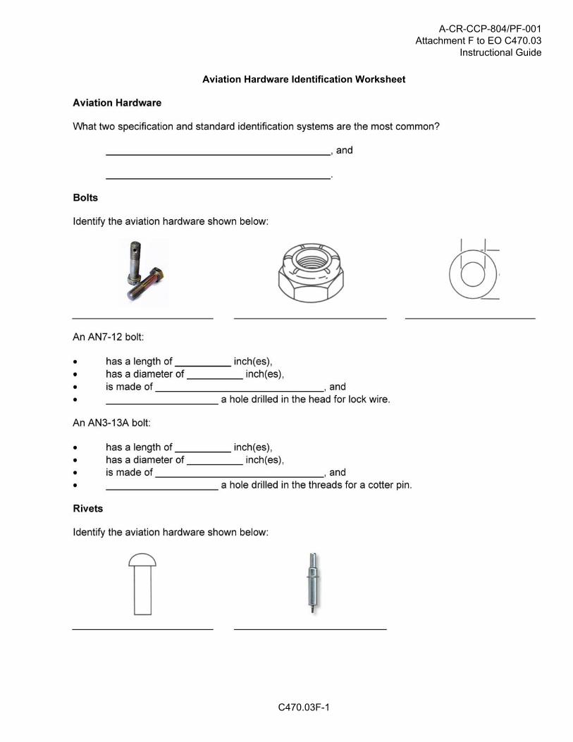
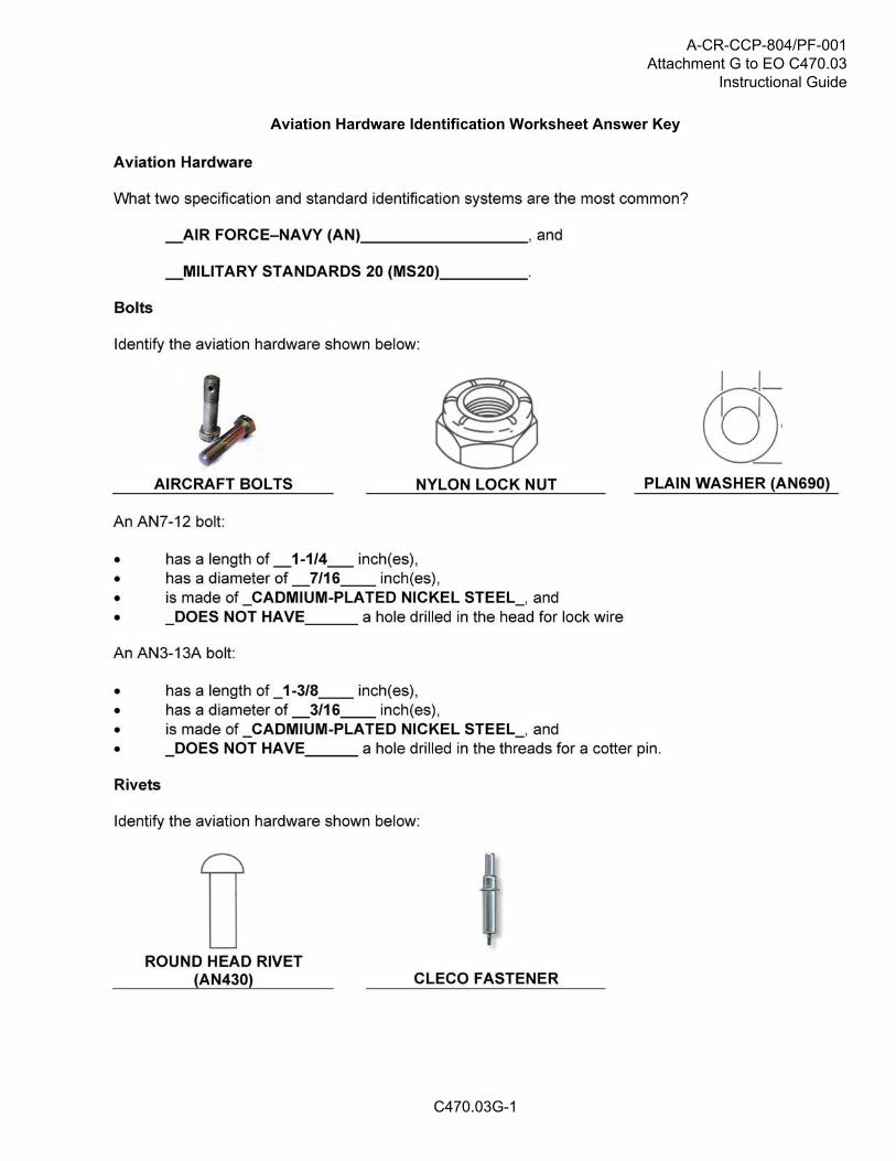
The two most common specification and standard identification systems used in aviation today are the AirForce–Navy (AN) and Military Standards 20 (MS20) systems. Both systems use a similar coding method todescribe the physical characteristics of aviation hardware (eg, rivets, bolts, nuts, etc). An example of this isshown in Figure A-2. While there are minor differences between different systems, the same piece of hardwarecan be described by different systems (eg, an AN365 self-locking nut is the same as a MS20365 self-lockingnut).
Rivet Designation Physical CharacteristicsAN Specification and standard (Air Force–Navy system)470 Head style (universal head)AD Material code (2117 aluminum alloy)4 Diameter (4/32 inch)
AN470-AD4-5
5 Length (5/16 inch)
Figure A-2 Rivet Specification Decoded
Note. Created by Director Cadets 3, 2009, Ottawa, ON: Department of National Defence.
Although there are many different types of fasteners used in aviation, there are five main categories:
bolts (includes washers and nuts),
rivets,
special fasteners,

A-CR-CCP-804/PF-001Attachment A to EO C470.03Instructional Guide
C470.03A-2
machine screws, and
turnlock fasteners.
Each category has its own unique terminology, although some terms may have similar meanings, as well asspecial tools and procedures for installation and removal.
Fasteners are used in two distinct applications in aviation: structural and non-structural. When used as astructural fastener, it is especially important that the correct hardware is used as the hardware forms part of thestructure of the aircraft and is expected to be able to carry a specific load without failing.
Examples of structural fasteners include:
bolts connecting the wing spar to the fuselage,
rivets connecting the wing skin to the wing ribs, and
bolts connecting the landing gear to the fuselage.
Examples of non-structural fasteners include:
turnlock fasteners on inspection covers and cowlings,
machine screws on interior panels, and
bolts holding instruments in place in the instrument panel.
Aircraft plans, parts manuals, and repair manuals all include very specific details on the exact type of aviationhardware to be used. Builders and maintenance personnel must not substitute alternate hardware withoutensuring that design specifications are not compromised.
When compared to standard or automotive hardware, aviation hardware is manufactured to higher standards,generally has a higher strength rating, and may come with a variety of finish or coating option. While non-aviation hardware may be legal for use on home-built aircraft, most associations strongly recommend the useof aviation hardware.

A-CR-CCP-804/PF-001Attachment B to EO C470.03
Instructional Guide
C470.03B-1
BOLTS
A bolt is designed to hold two or more items together. Bolts come in a variety of sizes, shapes, materials andstrengths so that the correct fastener can be used for each application. Bolts are used for both structural andnon-structural applications.
Figure B-1 AN (Airforce Navy) Bolt Dimensions
Note. From A&P Technician General Textbook (p. 8-17), by Jeppesen StandardTraining Products, 2000, Englewood, CO:Jeppesen Sanderson Training Systems.
Standard AN Bolt Classification
Standard bolts classified using the AN system, are classified using the diameter and length, and additionalmodifiers (eg, material, drilled holes) are added. Diameters are indicated in 1/16-inch increments and lengthin 1/8-inch increments.
For example, an AN4-7 bolt has a diameter of 4/16 inch (1/4 inch) and a length of 7/8 inch. The length of thebolt is also known as the dash number. Dash numbers of eight and nine (-8 and -9) are not used. This meansthat a bolt length of 1 inch is represented with -10 (2 inches is -20, 3 inches is -30). For example, an AN5-22bolt has a diameter of 5/16 inch and is 2-2/8 inches long (2-1/4 inches).
The material used for the bolt is indicated by replacing the dash with letters to indicate the material (the dashindicates that the bolt is made of cadmium-plated nickel steel). A corrosion-resistant bolt is represented withthe letter C. Aluminum alloy bolts use the letters DD.
Standard bolts have a hole drilled in the threaded portion for a cotter pin (to keep the nut from coming off). Toindicate a bolt without a hole, the letter A is added to the end of the bolt number (eg, AN5-22A). To indicate abolt that has a hole drilled in the head (for locking wire), the letter H is inserted after the diameter (eg, AN6H34).
Threads
Threads are classified by the number of threads per inch (the number of times the threads rotate [number ofturns] around a 1-inch length of a given diameter bolt or screw). Different standards for threads are AmericanNational Coarse (NC), American National Fine (NF), American Standard Unified Coarse (UNC), and AmericanStandard Unified Fine (UNF).
Threads are also designated by the class of fit (from one to five). A Class 1 thread is a loose fit (the nut maybe turned all the way from start to finish with just your fingers). A Class 5 thread is a tight fit (the nut requires awrench from start to finish). Most aviation bolts are fine threaded with a Class 3 fit.

A-CR-CCP-804/PF-001Attachment B to EO C470.03Instructional Guide
C470.03B-2
Nuts and Washers
Nuts are threaded onto the end of the bolt to prevent it from coming out. In some applications, the nut may alsocarry a load. Due to the vibrations experienced in a typical aircraft, most nuts must be locked onto the bolts. Tokeep the nut from coming loose, a cotter pin can be inserted through the hole in the bolt (a castle nut is usedin this type of application) or a lock nut (nylon or metal) is used.
Figure B-2 Standard Aircraft Nuts
Note. From A&P Technician General Textbook (p. 8-21), by Jeppesen StandardTraining Products, 2000, Englewood, CO:Jeppesen Sanderson Training Systems.
Washers are used to ensure that the bolt fits properly, to prevent the nut and / or bolt head from damaging theparts, and in the case of lock washers, to help prevent the nut from coming loose.
Figure B-3 Aircraft Washers
Note. From A&P Technician General Textbook (p. 8-30), by Jeppesen StandardTraining Products, 2000, Englewood, CO:Jeppesen Sanderson Training Systems.
A-CR-CCP-804/PF-001Attachment C to EO C470.03
Instructional Guide
C470.03C-1
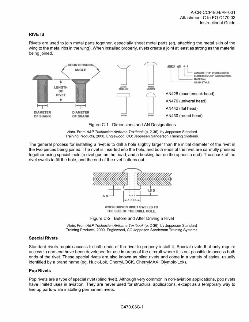
RIVETS
Rivets are used to join metal parts together, especially sheet metal parts (eg, attaching the metal skin of thewing to the metal ribs in the wing). When installed properly, rivets create a joint at least as strong as the materialbeing joined.
Figure C-1 Dimensions and AN Designations
Note. From A&P Technician Airframe Textbook (p. 2-36), by Jeppesen StandardTraining Products, 2000, Englewood, CO: Jeppesen Sanderson Training Systems.
The general process for installing a rivet is to drill a hole slightly larger than the initial diameter of the rivet inthe two pieces being joined. The rivet is inserted into the hole, and both ends of the rivet are carefully pressedtogether using special tools (a rivet gun on the head, and a bucking bar on the opposite end). The shank of therivet swells to fill the hole, and the end of the rivet flattens out.
Figure C-2 Before and After Driving a Rivet
Note. From A&P Technician Airframe Textbook (p. 2-36), by Jeppesen StandardTraining Products, 2000, Englewood, CO:Jeppesen Sanderson Training Systems.
Special Rivets
Standard rivets require access to both ends of the rivet to properly install it. Special rivets that only requireaccess to one end have been developed for use in areas of the aircraft where it is not possible to access bothends of the rivet. These special rivets are also known as blind rivets and come in a variety of styles, usuallyidentified by a brand name (eg, Huck-Lok, CherryLOCK, CherryMAX, Olympic-Lok).
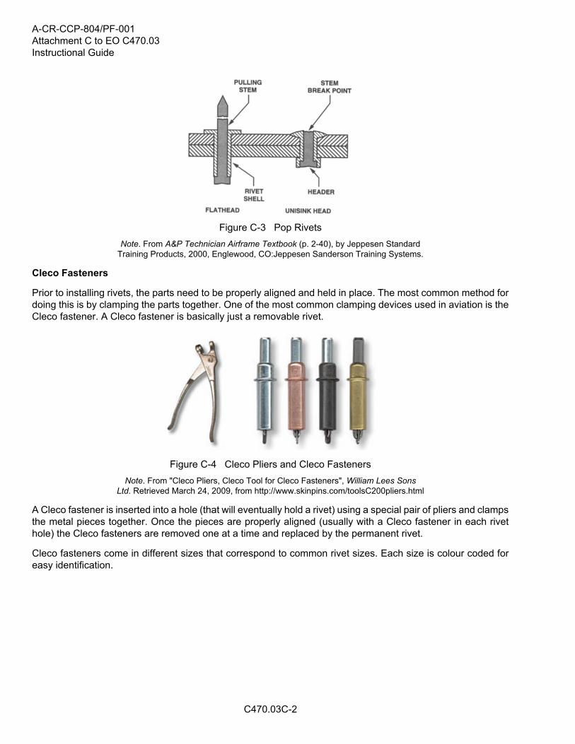
Pop Rivets
Pop rivets are a type of special rivet (blind rivet). Although very common in non-aviation applications, pop rivetshave limited uses in aviation. They are never used for structural applications, except as a temporary way toline up parts while installing permanent rivets.
A-CR-CCP-804/PF-001Attachment C to EO C470.03Instructional Guide
C470.03C-2
Figure C-3 Pop Rivets
Note. From A&P Technician Airframe Textbook (p. 2-40), by Jeppesen StandardTraining Products, 2000, Englewood, CO:Jeppesen Sanderson Training Systems.
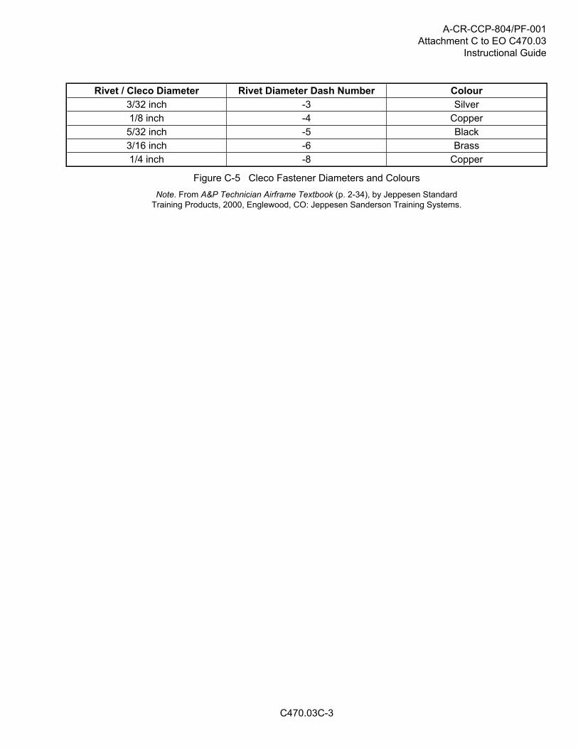
Cleco Fasteners
Prior to installing rivets, the parts need to be properly aligned and held in place. The most common method fordoing this is by clamping the parts together. One of the most common clamping devices used in aviation is theCleco fastener. A Cleco fastener is basically just a removable rivet.
Figure C-4 Cleco Pliers and Cleco Fasteners
Note. From "Cleco Pliers, Cleco Tool for Cleco Fasteners", William Lees SonsLtd. Retrieved March 24, 2009, from http://www.skinpins.com/toolsC200pliers.html
A Cleco fastener is inserted into a hole (that will eventually hold a rivet) using a special pair of pliers and clampsthe metal pieces together. Once the pieces are properly aligned (usually with a Cleco fastener in each rivethole) the Cleco fasteners are removed one at a time and replaced by the permanent rivet.
Cleco fasteners come in different sizes that correspond to common rivet sizes. Each size is colour coded foreasy identification.
A-CR-CCP-804/PF-001Attachment C to EO C470.03
Instructional Guide
C470.03C-3
Rivet / Cleco Diameter Rivet Diameter Dash Number Colour3/32 inch -3 Silver1/8 inch -4 Copper
5/32 inch -5 Black3/16 inch -6 Brass1/4 inch -8 Copper
Figure C-5 Cleco Fastener Diameters and Colours
Note. From A&P Technician Airframe Textbook (p. 2-34), by Jeppesen StandardTraining Products, 2000, Englewood, CO: Jeppesen Sanderson Training Systems.

A-CR-CCP-804/PF-001Attachment C to EO C470.03Instructional Guide
THIS PAGE INTENTIONALLY LEFT BLANK
C470.03C-4

A-CR-CCP-804/PF-001Attachment D to EO C470.03
Instructional Guide
C470.03D-1
SCREWS
Screws are a very common threaded fastener in aviation and there are three basic classifications: machinescrews, structural screws, and self-tapping screws. Screws generally have a loose fitting thread (eg, Class 2)and may have either a clearly defined grip length that is partially threaded or be threaded along their entirelength. While most screws have heads designed to accept a screwdriver, some have heads that require awrench.
Machine Screws
Machine screws are generally used for attaching fairings, inspection plates, fluid line clamps, and other lightstructural parts. Machine screws are usually threaded along their entire length and are available with nationalcoarse or national fine threads. These screws may be made of several different types of materials and maybe coated or treated in various ways.
Figure D-1 Machine Screws
Note. From A&P Technician General Textbook (p. 8-27), by Jeppesen StandardTraining Products, 2000, Englewood, CO:Jeppesen Sanderson Training Systems.
Structural Screws
Structural screws are very similar to standard bolts. They are heat treated and have the same shear strengthas a bolt of the same size. Shank tolerances are similar to bolts and the threads are national fine.
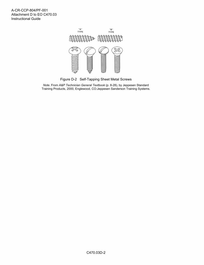
Self-Tapping Screws
Self-tapping screws are used to hold thin sheets of metal, plastic, or plywood together. They have a coarsethread and come with a sharp (Type A) or blunt (Type B) point.
A-CR-CCP-804/PF-001Attachment D to EO C470.03Instructional Guide
C470.03D-2
Figure D-2 Self-Tapping Sheet Metal Screws
Note. From A&P Technician General Textbook (p. 8-28), by Jeppesen StandardTraining Products, 2000, Englewood, CO:Jeppesen Sanderson Training Systems.
A-CR-CCP-804/PF-001Attachment E to EO C470.03
Instructional Guide
C470.03E-1
TURNLOCK FASTENERS
Turnlock fasteners are used when quick and easy removal or opening of access panels, doors, and cowlingsis required. There are three common types, each identified by their trade or brand name: Dzus, Airloc, andCamlock.
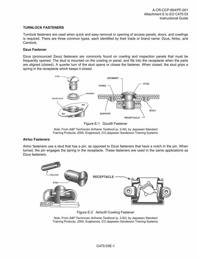
Dzus Fastener
Dzus (pronounced Zeus) fasteners are commonly found on cowling and inspection panels that must befrequently opened. The stud is mounted on the cowling or panel, and fits into the receptacle when the partsare aligned (closed). A quarter turn of the stud opens or closes the fastener. When closed, the stud grips aspring in the receptacle which keeps it closed.
Figure E-1 Dzus® Fastener
Note. From A&P Technician Airframe Textbook (p. 2-49), by Jeppesen StandardTraining Products, 2000, Englewood, CO:Jeppesen Sanderson Training Systems.
Airloc Fasteners
Airloc fasteners use a stud that has a pin, as opposed to Dzus fasteners that have a notch in the pin. Whenturned, the pin engages the spring in the receptacle. These fasteners are used in the same applications asDzus fasteners.
Figure E-2 Airloc® Cowling Fastener
Note. From A&P Technician Airframe Textbook (p. 2-50), by Jeppesen StandardTraining Products, 2000, Englewood, CO:Jeppesen Sanderson Training Systems.

A-CR-CCP-804/PF-001Attachment E to EO C470.03Instructional Guide
C470.03E-2
Camlock Fasteners
Camlock fasteners have a stud assembly that includes a spring and a pin. When the stud is pressed into thereceptacle, the spring compresses and allows the pin to be rotated into position in the receptacle. When thestud is released, the spring expands, and holds the pin in place in a groove in the bottom of the receptacle.
Figure E-3 Camlock® Cowling Fastener
Note. From A&P Technician Airframe Textbook (p. 2-50), by Jeppesen StandardTraining Products, 2000, Englewood, CO:Jeppesen Sanderson Training Systems.
A-CR-CCP-804/PF-001Attachment F to EO C470.03
Instructional Guide
C470.03F-1
Aviation Hardware Identification Worksheet

A-CR-CCP-804/PF-001Attachment F to EO C470.03Instructional Guide
C470.03F-2
A-CR-CCP-804/PF-001Attachment G to EO C470.03
Instructional Guide
C470.03G-1
Aviation Hardware Identification Worksheet Answer Key

A-CR-CCP-804/PF-001Attachment G to EO C470.03Instructional Guide
C470.03G-2