toys save millons(3)
DESCRIPTION
'Toys that save millions' - a history of using physical models in structural design. by Bill Addis MA (Cantab), PhD Consulting engineerTRANSCRIPT
12 TheStructuralEngineer Feature
›
Toys that save millionsApril 2013
IntroductionScope of the paper
Building designers have been using models for at least 2500 years. This paper addresses only those aspects of model testing that structural engineers have used during the design stages of projects to determine quantitative results regarding structural form, defl ections, stresses, bending moments, wind loads, dynamic behaviour, ultimate strength, stability, collapse loads and factors of safety. The author has discussed many of these issues in greater detail, as well as some of the philosophy underlying model testing, previously1-6. The paper does not look at the use of models to convey the geometry of buildings to clients or builders, or to check the viability of construction and assembly, or as part of scientifi c research into structural behaviour, or to learn about structural behaviour and gain a physical feeling of the behaviour of structures.
Why did engineers do model testing?
The task of the structural engineer is twofold:
• To provide dimensions of components and their relative disposition, as well as materials specifi cations, to enable a contractor to begin construction• To raise the confi dence of the engineer and builder such that a proposed structure can be constructed and, once constructed, will work as intended
The purpose of testing scale models of structures was to help the designer achieve these two goals when calculations using structural theory were judged to be inadequate or would have been too complex or time-consuming. This situation often arose when new, unprecedented types of structure were being developed, and was encountered particularly during the 20th century in the design of thin reinforced concrete shells and lattice shells, of both reinforced concrete and timber.
Why is the topic important?
The contribution of structural theory to the development of structural engineering has long been recognised, and is the subject of many excellent studies7-10. The contribution of model testing, both to the design of many extraordinary and innovative structures and, more generally, to progress in structural engineering has, on the other hand, not been duly recognised and has been addressed by very few historians of structural engineering11-13. It is the author’s view that the two aspects are of equal importance, especially since the late 19th century, and that much research is needed to redress the current imbalance.
Bill Addis MA (Cantab), PhD Consulting engineer
'Toys that save millions' - a history of using physical models in structural design
SynopsisSmall-scale physical models have been used to determine the most effi cient form of pure compression and tensile structures since the 17th century - and to predict structural behaviour of some full-size structures since the mid-19th century. This paper traces the development of model testing in the design of building structures from its origins in the design of bridges and ship hulls in the 19th century, to the design of gravity and arch dams in the early 20th century, through the early days of designing concrete shell roofs in the 1920s and 1930s, to its most sophisticated use in the 1960s and (in conjunction with computer modelling) the 1970s. The great strength of model testing was, and is, to deal with new types of structures without design codes and even without precedent.
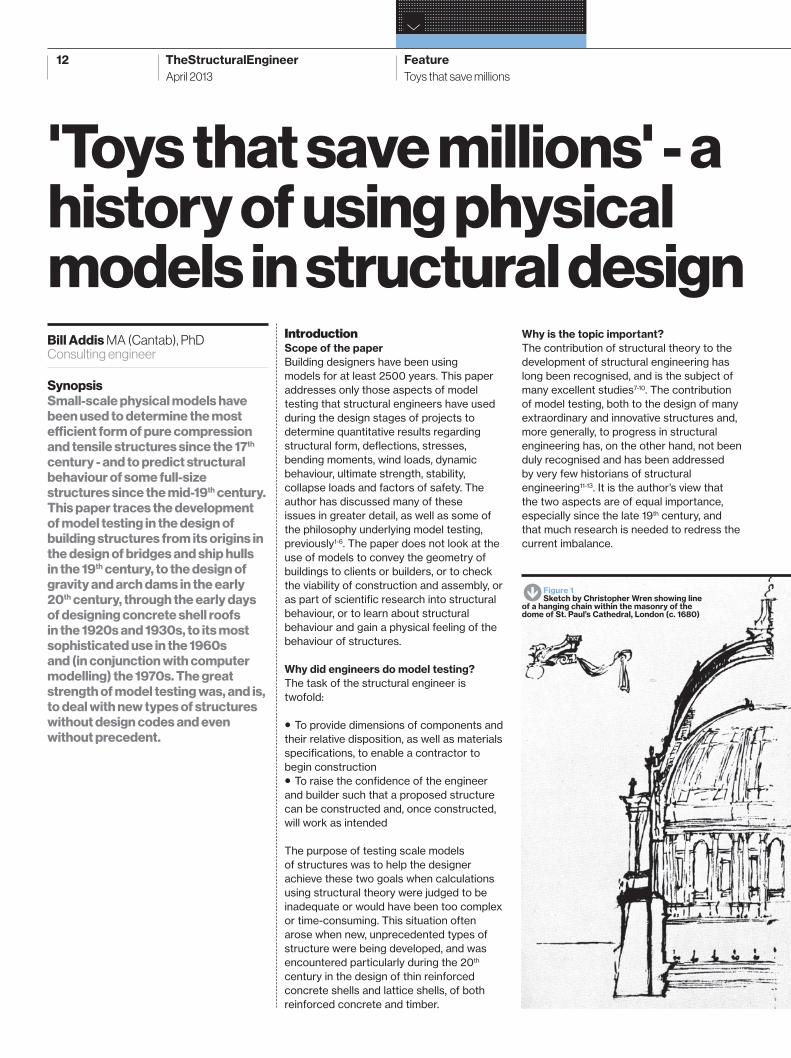
S Figure 1Sketch by Christopher Wren showing line
of a hanging chain within the masonry of the dome of St. Paul’s Cathedral, London (c. 1680)
TSE16_12-27.indd 12TSE16_12-27.indd 12 22/03/2013 13:2822/03/2013 13:28
13
www.thestructuralengineer.org
The characteristics of scale models
At an intuitive level, most people would assume that the behaviour of a model test can be scaled up linearly to full size. However, this is not the case for all types of structure. There are two types of structural phenomena or behaviour. Those that can be scaled up linearly, such as:
• the linear dimensions of a structure• the shape of a hanging chain of weights or a membrane; and, by Hooke’s inversion law, of funicular arches, vaults and domes• the stability of masonry compression structures, including arches, vaults and domes
and those that cannot, such as:
• the mass of a structure• the strength and stiff ness of a beam• the buckling load of a column or thin shell
This observation explains why masonry structures were able to develop so spectacularly, long before any scientifi c or mathematical understanding of structural behaviour. A model arch, vault or dome can be reliably used to predict the behaviour of a similar, full-sized structure.
Although we have no convincing evidence,
it must have been the case that ancient builders knew that making models of some types of structure worked as a design process, while for others, it did not. But they probably did not realise the signifi cance of what they knew. The earliest mention of the non-linearity of scaling was by Galileo who noted (in what we now call the square:cube law) that while area increases with the square of the scale factor, the volume and hence the mass, increases as the cube of the scale. He used this observation to explain that the limited strength of bone material means the size of animals cannot be scaled up indefi nitely.
Ancient builders also did not realise that what distinguishes the two categories of phenomena is that the fi rst is independent of the structural properties of the materials involved, while the second is not. This was fi rst understood only in the 18th century when scientists began using the concept of elasticity.
Making the scale model of a structure is the fi rst stage of the process. It is then subjected to certain loads and the behaviour of the model - its deformation and ultimately, perhaps, its collapse or the failure of one of its members - is observed. Just as with a virtual model of a structure, there are four aspects to making a scale model:
• its geometry – the size and disposition of members and components• the nature of structural connections including boundary conditions• the model loads• models of the structural materials
In each case the relationship between the model and the full-size artefact (the similarity) need to be identifi ed. For example:
• Are all dimensions reduced by the same scale factor? Reducing to scale a thin shell or membrane, and bolts or reinforcing rods may be impractical• While a real connection may be welded or riveted, it may be more appropriate to model it as pin-jointed. A support on a foundation might be modelled using a spring• How to model the self-weight of the structure will depend on the density of the model material. Wind loads may be modelled using weights• Material properties cannot be scaled; the stiff ness and thermal expansion of steel are independent of scale. Also, if a model is made of a 'full-size' material such as steel, while the loads are scaled down, then defl ections are likely to be extremely diffi cult to measure. It might be appropriate to replace steel by a less stiff material such as celluloid or Perspex
Hence, it is not possible to make a single scale-model structure that represents the full-size structure and its behaviour in every respect. When several models are needed, the purpose of each model and test must be decided before making and testing it. In order to select the precise ways in which the model does represent the full-size structure, the precise eff ect of scale on the behaviour must also be understood.
Use of dimensionless numbers
Even when the theoretical models of a certain engineering performance are not understood, or too complex for mathematical treatment, it is possible to establish the relationship between the performance of a scale model and the full-size prototype. The technique was developed by a number of physicists in the 1860s to deal with the mechanics of fl uid fl ow. They established several dimensionless numbers (e.g. Reynolds Number) whose value, for a certain problem, having no dimensions, is constant and independent of scale.
William Froude (1810-1879) had worked with Isambard K. Brunel on the design of the SS Great Eastern, the largest ship in the world in 1853. In the mid-1860s, when working for the Admiralty, Froude was asked to determine the most economic shape for a ship’s hull – in other words to determine the resistance to movement of a full-size ship and, hence, the size of steam engine needed to drive the ship at a certain speed. He realised that friction was not the only resistance to the motion of a ship; the surface wave created by a ship also impeded its movement. He discovered a dimensionless number that related the variables V (the velocity of the ship) and L (its length). Fr, the Froude Number, is given by V/√(gL). This insight led him to believe, against the opinions of everyone else involved, that models of ships’ hulls might be used to predict the performance of full-size ships. He concluded that the wave resistance of the model and a full-size ship would be proportional if the Froude Number for the model and prototype had the same value. In 1867 Froude tested models of two diff erent hull shapes in three sizes; 3, 6 and 12ft long, and found that they generated similar wave patterns when towed at speeds proportional to the square of the length of the models. In 1871, Froude conducted the fi rst model tests that infl uenced the design of a ship, HMS Greyhound. The sea trials a year later showed Froude’s design method to be a complete success.
The use of dimensionless numbers by engineers in other disciplines was made possible by the work of a number of mathematicians in the 1890s and early
TSE16_12-27.indd 13TSE16_12-27.indd 13 22/03/2013 13:2822/03/2013 13:28

14 TheStructuralEngineer Feature
›
Toys that save millionsApril 2013
1900s, culminating with the American physicist Edgar Buckingham (1867-1940) who in 1914 published his famous theorem of dimensional analysis14. This theorem provides a general means of determining all the dimensionless numbers that involve a certain number of physical variables of a system, even when the precise form of the equation relating the variables remains unknown. The use of dimensionless numbers and Buckingham’s pi-theorem was widely disseminated via the classic book on the subject by P. W. Bridgman (1882-1961), which remained in print for more than more than 40 years15. Nevertheless, it was not until the early 1950s that structural model testing began to exploit the benefi ts of dimensionless numbers.
Using models to determine the form of building structuresCompression structures
The earliest evidence we have of a model being used to help determine the form of a structure was by Robert Hooke (1635-1703) and Christopher Wren (1632-1723) for the dome of London's St Paul’s Cathedral. In 1676 Hooke noted that the equilibrium form of an arch was the same (although inverted) as a hanging chain comprising the same weights as the arch. One of Wren’s sketches for the dome shows the shape of a chain suspended over a cross section of the building (Figure 1). At the very least this demonstrated that the catenary arch lay within the masonry, although it appears that a uniform chain was used rather than a series of diff erent weights representing the voussoirs of diff erent sizes. Giovanni Poleni (1682-1761) used Hooke’s principle in the 1740s, this time using a chain with diff erent sized weights representing the voussoirs, to help demonstrate that the 100 year old dome of St Peter’s Cathedral in Rome was stable despite some radial cracks16.
A century later, the German engineer Heinrich Hübsch (1795-1863) used hanging string models to determine the weights of voussoirs needed to achieve the desired shape of an arch or vault shape17 (Figure 2). The same method was used in 1837 for the design of a (roughly) hemispherical dome covering a foundry in Kassel, Germany. The 16m diameter dome was made with hollow clay pots which were both lightweight and fi reproof. Using Hübsch’s method, the foundry owner who built the dome was able to reduce its thickness to 175mm for the upper two-thirds of the dome18.
During the second half of the 19th century a number of books recommended the use of hanging models to establish the best geometry for arches and vaults. In the 1890 revised edition of Ungewitter’s
classic book on Gothic construction, Karl Mohrmann specifi cally recommended the use of three-dimensional hanging models19. Friedrich Gösling (1837-99) used both two- and three-dimensional models for some of his designs20 (Figure 3). Rather better known is the work of the Catalan architect Antoni Gaudí (1852-1926) who used both two- and three-dimensional hanging models, made with strings and bags of sand to help establish the forms of arches and vaults for several of his masonry buildings. The most well-known of these models was for The Church of Colònia Guell (Figure 4) and he used similar models for other projects that were not built21. Gaudí used the results of his model tests to complement his use of both statical calculations and graphical statical methods to determine the forms of the tree-like columns and vaults.
Heinz Isler (1926-2009) was the last of the great concrete shell builders of the 20th century and, like many before him, brought his own unique approach to the challenge. He took into three dimensions Hooke’s premise about the inverted catenary using various sheet and membrane materials to make hanging models, which he then scaled up to reproduce their funicular geometry at full size. One technique he used was to soak a piece of cloth in liquid plaster of Paris and allow it to harden; another was to soak a piece of cloth in water and hang it in the open air during a Swiss winter night to freeze the shape (Figure 5). Not only were these techniques able to generate the form of the main shell, but also the folds that provide stiff ening to the free edges of the shells. Isler used other model techniques to create both funicular and non-funicular structural forms, including using air pressure to infl ate elastic membranes. Isler was thus able to generate forms whose geometry he could defi ne and
N Figure 2Investigation of form and construction of various
vaults using a hanging chain by Heinrich Hübsch (c. 1835)
W Figure 3Form-fi nding of arches and vaults using
hanging chains by Friedrich Gösling (c. 1890)
S Figure 4Reproduction of Gaudí’s hanging model
for The Church of Colònia Guell, Barcelona
RA
INE
R G
RA
EF
E
RA
INE
R G
RA
EF
EB
ILL
AD
DIS
TSE16_12-27.indd 14TSE16_12-27.indd 14 22/03/2013 13:2822/03/2013 13:28

15
whose structural behaviour he could then analyse in detail. He used statical and elastic calculations to determine the appropriate reinforcement needed to achieve the necessary strength, stiff ness and resistance to buckling22.
While Frei Otto (1925-) is perhaps best-known for his many tensile structures, he used the same modelling techniques for a number of compression structures, including timber lattice shells, the largest of which (Mannheim) is discussed later.
Tension structures
Hanging-chain models were used in the design of suspension bridges from their earliest days in the early 19th century, for example by Thomas Telford (1757-1834) in 181423. The models were used to establish the geometry of the catenary and how it varied with the loads hanging from the chain while maintaining the tension at the ends of the catenary constant, in order to determine the length for the many hangers used to support the roadway.
Frei Otto was a great innovator in the use of models to determine the form of tension structures. He began using models in the 1950s as the only way of establishing the form of three-dimensional, membrane and cable-net structures whose fi nal geometry could not, at the time (before computers), be determined using analytical methods24. Since gravity loads played a minor part in establishing the form of the tensile structures, the models themselves were made of membranes or nets with diff erent characteristics: soap bubbles which have a constant surface tension; elastic sheets whose surface tension depends on the strain; and nets whose surface tension arises partly from the elastic extension of fi bres, and partly from shear deformations of the net (squares to rhombuses). Otto and his colleagues at the Institute for Lightweight Structures in Stuttgart developed a large
range of modelling techniques, including making soap bubbles up to 1m wide (Figure 6), as well as ingenious methods for measuring and surveying their complex forms which could not be defi ned using mathematical models. Having established the equilibrium geometry of the tensile structure, it was then possible to use analytical methods to determine in-plane stresses and forces at the boundary supports.
Early history of using models to predict structural behaviourStructures before 1900
There are references in the writings of both Palladio (1508-1580) and Claude Perrault (1613-1688) to loading models of timber bridges and scaling dimensions up to full size, in direct proportion. One of the earliest references to the use of a model test to predict the strength of an unbuilt structure, occurs in a book by the German bridge engineer Caspar Walter (1701-1769). In 1766 Walter described a 1:20 scale model he made of a 250ft span timber bridge which he loaded with ‘10cwt and 10 strong men’ (a total of about 25cwt or 1.25tons). He used this test to argue that the full-scale bridge would carry at least 25tons, indicating that he too used direct proportion when scaling up to full size. Leonard Euler (1707-1783) knew of Walter’s work and realised that it was incorrect to use simple direct proportion. Taking into account the self-weight of the structure, he gave diff erent factors by which diff erent
dimensions in the model should be scaled up to full size. However, Euler’s precocious understanding of scale eff ects in model tests had little infl uence on designers of timber bridges who, by the early 19th century were beginning to use statics to help determine the dimensions of their bridges25.
The introduction of iron as a structural material for bridges, and the use of unprecedented structural forms, again pushed engineers to use models to help them to design a structure. The most well-known example was the Britannia Bridge, with a continuous wrought-iron box girder spanning over 450m, with two central spans of 150m. This was unprecedented in terms of its size, its box-girder form and for being a continuous girder with hogging bending moments over intermediate supports. Models of wrought iron, some at 1:6 scale, were used to compare diff erent cross sections, to fi nd the most eff ective means of stiff ening the walls of the tubes to resist bucking, and to determine the strength of the girders, using bending theory to scale the results up to full size26. Though beyond the scope of this paper, it should be noted that many other engineers around this time used model tests; indeed William Airy commented in the discussion of a paper on using models to determine forces in a bowstring truss bridge: 'It was no unusual thing for an engineer, with an important or extraordinary work on his hands, to have a model made of the intended structure for the purposes of experiment, if it was thought that thereby results might be arrived at aff ecting the security and expense of the work' 27.
Dams before 1920
The use of models to study the behaviour of structures other than bridges seems to date back to mid-1890s when Benjamin Baker (1840-1907) made and tested a model of the Aswan dam during his work on its design. He wanted to establish the stability of the
W Figure 5Form-fi nding model by Heinz Isler for
concrete shell roof using frozen cloth
E Figure 6Form-fi nding model (image inverted) by
Frei Otto for a tensile membrane roof, using a soap bubble approximately 1m wide.
HE
INZ
ISLE
R
INS
TIT
UT
E F
OR
LIG
HT
WE
IGH
T S
TR
UC
TU
RE
S, S
TU
TT
GA
RT
www.thestructuralengineer.org
TSE16_12-27.indd 15TSE16_12-27.indd 15 22/03/2013 13:2922/03/2013 13:29
16 TheStructuralEngineer Feature
›
Toys that save millionsApril 2013
proposed trapezoidal cross-section against overturning, and the distribution of stresses in the solid masonry dam. He used his model, made of 'ordinary jelly' and probably about 200mm high, to corroborate the design calculations that had been made assuming a dam behaved as a homogenous elastic body28. Baker resorted to models again in 1904-1905 when it was proposed to raise the height of the dam after the foundations and lower sections had been constructed. This time Baker used ‘nearly a dozen stiff jelly models’ during a period of 3 or 4 hours to determine the safety factor of the raised dam. He concluded it would be safe, as long as the base of the dam was better protected from damage by scour. It is worth noting that when Baker had been designing the Forth Bridge in the 1880s he had made a detailed study of all the model tests undertaken during the design of Stevenson’s Britannia Bridge in the 1840s, so he was familiar with the value of model tests. It is also worth noting that many dam engineers, including Baker, had used models from the 1870s to determine fl ow rates of water in open channels and spillways.
In parallel with Baker’s tests, one of the other engineering scientists who had undertaken the original elastic calculations for the Aswan dam, undertook tests of two physical models of the wooden section of the dam29. One model consisted of several vertical strips of wood that resisted overturning by the friction between the strips, representing vertical shear forces. The other consisted of horizontal pieces of wood that resisted overturning by friction between the strips, representing horizontal shear forces.
A few years later another research team
undertaking tests on dam sections were conscious of the need to take into account scale eff ects in their model. They sought a material for the model dam 'whose strength would be in something like the same ratio to the strength of masonry as the size of the model was to the size of the dam'. Their search led them to choose Plasticine®, which had been patented in 1899, limiting the tests to its elastic range30. To their surprise and delight they found that, when loaded at low stresses for a long period of time, the Plasticine® would fracture perpendicular to the tensile stresses, thus giving them information about internal stresses in the dam section. The model was 750mm high with a base of 650mm and length of 300mm. It was loaded using an India-rubber bag fi lled with water, and movement of the dam was observed through the glass plates at each end of (but not touching) the model. Both the glass plates and the ends of the model were marked with an orthogonal grid of lines at 50mm spacing so that their relative movement could be measured. The tests yielded data about the distribution of stresses within the dam and at its base.
Finally in this rush of research activity into dams, another research team used models of dam sections about 150mm high and 25mm thick, made of India-rubber31. The loads were applied mechanically using weights, fi shing line and pulleys. The deformations were recorded photographically and measured at leisure to an accuracy of one thousandth of an inch (0.025mm). These tests took into account the scaling factors for both stiff ness and Poisson’s ratio and displayed the results as ellipses of stress, thus indicating the lines of principal stress.
Dams in the 1920s
Two factors contributed to a huge transformation in the use of models in the 1920s. In 1902 the western states of the USA formed the Reclamation Service (later the Bureau of Reclamation) to prevent the terrible damage caused by regular fl ooding. The Bureau was given an enormous budget for research into the construction of dams, both for fl ood management and the generation of hydroelectric power. One major research theme, from about 1920, was to develop reinforced concrete arch dams as an alternative to conventional cantilever gravity dams. In essence, these were thin concrete shells, not too remote from the concrete shell roofs that were being developed in several European countries from around 1900.
For the fi rst arch dams built in the early years of the 20th century, the theoretical analysis of the dam treated the shell as a cylinder. However, this was far from ideal since, at each higher level in the shell, the arch elements had increasingly longer spans, and there were signifi cant discontinuities between adjacent arch elements. Despite various attempts at resolving these diffi culties, it became widely agreed that the mathematical models being used were still not adequately representative of the real structure.
In 1923 a proposal was made to the Bureau's board to build an experimental arch dam to investigate thoroughly the behaviour of the concrete shell. The experimental dam at Stevenson Creek, California, was 19m high, reducing in thickness from 2.3m at the base to 600mm for the entire top half of the dam. This slim profi le was unprecedented. It was also decided that model tests of the dam should be undertaken, not only to predict stresses and deformations during the design process, but also, by comparing the behaviour of the full-size dam with the predictions from the model, to test the reliability of using model tests in the design process. One of the researchers was a young engineer, Dr Fredrik Vogt (1892-1970), who had previously performed tests on model dams made of stiff rubber in his native country of Norway. Now working at the University of Denver, he led the model-testing programme on the Experimental Dam. The main model was made of concrete and built at 1:12 scale, 1.5m high and just 50mm thick at the top of the dam. The concrete was made using rock aggregate from the site of the real dam, and the model was loaded using mercury in a rubber bag. Testing began in 1926 and, after a full programme of elastic tests, the main model was loaded to destruction in December 1928. Measurements taken from the model and the full-size dam were in
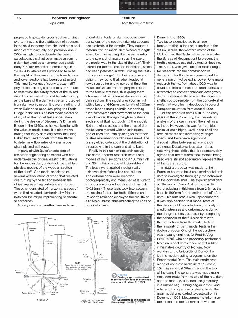
W Figure 7Development of mechanical
strain gauge rosette (c. 1931)
N Figure 8Strain gauge rosettes fi xed
to the upstream face of 1:180 scale model in stiff rubber (c. 1933)
BU
RE
AU
OF
RE
CLA
MA
TIO
N
BU
RE
AU
OF
RE
CLA
MA
TIO
N
TSE16_12-27.indd 16TSE16_12-27.indd 16 22/03/2013 13:2922/03/2013 13:29
17
close agreement and were used to check and improve the mathematical model used for the theoretical analysis. The model tests allowed the researchers to draw the following principal conclusions:
• A properly constructed small scale model can be relied upon to produce strains and deformations similar to its prototype• Mercury is a satisfactory medium for producing model testing loads• The trial load method* of analysis gives accurate results for a thin arch dam
The experience gained on the Stevenson Creek Experimental Dam was carried over to the 60m high Gibson Dam in Montana (1926-1929) for which a 1:68 scale model
was tested. Using this model they studied not only the defl ections of the dam under pressure, but also movement of the dam due to temperature diff erentials, which could be particularly severe during the later stages of construction. Finally in this era of building great dams, came the enormous Boulder Dam on the Arizona/Nevada border (now the Hoover Dam) (1930-1936), which was 221m high. During the design of the project three models were tested: one at 1:240 scale made of plaster and earth; one at 1:180 scale made of stiff rubber; and a 1:120 scale model of the top half of the dam only. With these models they investigated the radial and tangential movement of the top of the dam, the deformation and strain on both surfaces of the dam, and the eff ects of temperature diff erentials. The fi nal report, published in 1939, included the fi rst comprehensive discussion of model testing of structures, including how they dealt with the scale eff ects between model and full-size structure for the many variables involved32.
Of particular note was the mechanical strain gauge the research team developed in 1931 to measure the surface strains of the models (Figures 7 and 8). Each rosette (as they are now known) had three gauges with a gauge length of 75mm and measured strains in three directions 0°, 45° and 90°. Strains were magnifi ed using a simple lever arm showing readings on a 50mm scale, enabling measurements to be made to 1/10 000 inch (0.0025mm).
In parallel with the model tests on the Stevenson Creek Experimental Dam, undertaken by Dr Vogt, a diff erent technique of model testing was used by Professor George E. Beggs (1883-1939) at Princeton
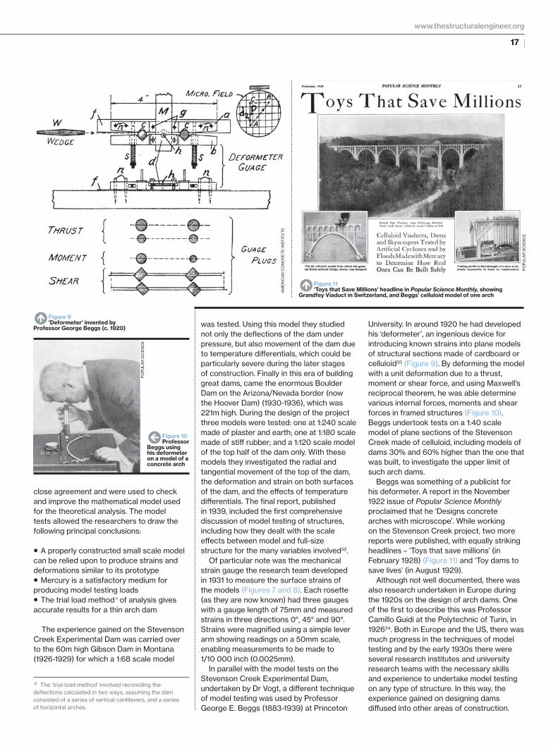
University. In around 1920 he had developed his ‘deformeter’, an ingenious device for introducing known strains into plane models of structural sections made of cardboard or celluloid33 (Figure 9). By deforming the model with a unit deformation due to a thrust, moment or shear force, and using Maxwell’s reciprocal theorem, he was able determine various internal forces, moments and shear forces in framed structures (Figure 10). Beggs undertook tests on a 1:40 scale model of plane sections of the Stevenson Creek made of celluloid, including models of dams 30% and 60% higher than the one that was built, to investigate the upper limit of such arch dams.
Beggs was something of a publicist for his deformeter. A report in the November 1922 issue of Popular Science Monthly proclaimed that he ‘Designs concrete arches with microscope’. While working on the Stevenson Creek project, two more reports were published, with equally striking headlines – ‘Toys that save millions’ (in February 1928) (Figure 11) and ‘Toy dams to save lives’ (in August 1929).
Although not well documented, there was also research undertaken in Europe during the 1920s on the design of arch dams. One of the fi rst to describe this was Professor Camillo Guidi at the Polytechnic of Turin, in 192634. Both in Europe and the US, there was much progress in the techniques of model testing and by the early 1930s there were several research institutes and university research teams with the necessary skills and experience to undertake model testing on any type of structure. In this way, the experience gained on designing dams diff used into other areas of construction.
N Figure 9'Deformeter' invented by
Professor George Beggs (c. 1920)
N Figure 11'Toys that Save Millions' headline in Popular Science Monthly, showing
Grandfey Viaduct in Switzerland, and Beggs’ celluloid model of one arch
W Figure 10Professor
Beggs using his deformeter on a model of a concrete arch
AM
ER
ICA
N C
ON
CR
ET
E IN
ST
ITU
TE
PO
PU
LAR
SC
IEN
CE
PO
PU
LAR
SC
IEN
CE
* The ‘trial load method’ involved reconciling the defl ections calculated in two ways, assuming the dam consisted of a series of vertical cantilevers, and a series of horizontal arches.
www.thestructuralengineer.org
TSE16_12-27.indd 17TSE16_12-27.indd 17 22/03/2013 13:2922/03/2013 13:29
18 TheStructuralEngineer Feature
›
Toys that save millionsApril 2013
Photoelastic stress analysis
Although seldom used in the design of buildings, photoelastic stress analysis played an important role in the development of experimental stress analysis in the fi rst half of the 20th century. In the 1930s, any laboratory undertaking model testing for the design of dams would have used photoelastic stress analysis as well as models made of concrete, plaster or rubber. The technique depends on the property of certain transparent materials, including glass, celluloid and some epoxy resins, to change the refractive index in proportion to internal stresses. Interestingly, the Scottish physicist David Brewster (1781-1868) who discovered this optical phenomenon in 1805, suggested it would be useful for investigating forces in arch bridges. This was realised for the fi rst time over a century later, between 1910 and 1920, by the engineering Professors Augustin Mesnager (1862-1933) in France and Ernest Coker (1859-1946) and Louis Filon (1875-1937) in England. Its most sophisticated application was in the aircraft industry until the early 1970s. In the construction industry its most valuable role was in determining the fl ow of forces (stresses) through steel connections in which rivet holes or welds caused unusual load paths and stress concentrations.
Early 20th century use of models in the design of building structuresThin reinforced concrete shells
Early designers of concrete shells used membrane analysis to determine bending moments in simple shells, but it was not at all useful for analysing the buckling behaviour of the thin concrete sections. Engineers turned to model testing as a design tool when they began to increase the span and reduce the thickness of concrete shells in the mid-1920s.
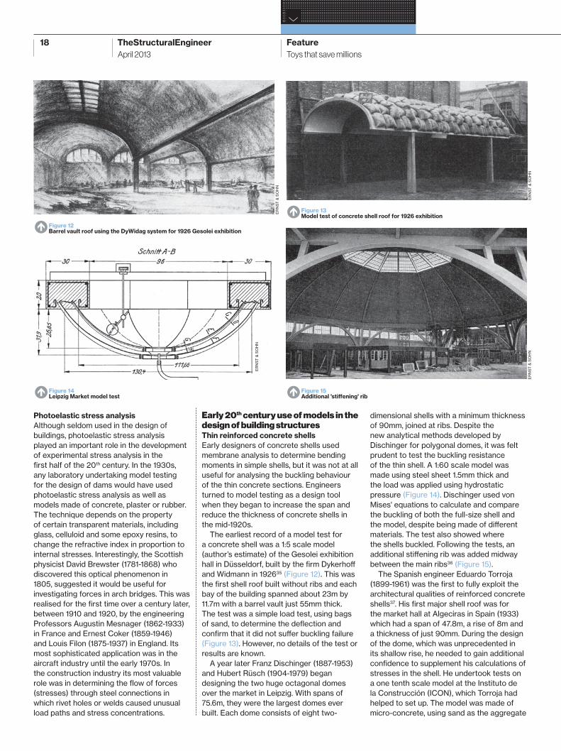
The earliest record of a model test for a concrete shell was a 1:5 scale model (author’s estimate) of the Gesolei exhibition hall in Düsseldorf, built by the fi rm Dykerhoff and Widmann in 192635 (Figure 12). This was the fi rst shell roof built without ribs and each bay of the building spanned about 23m by 11.7m with a barrel vault just 55mm thick. The test was a simple load test, using bags of sand, to determine the defl ection and confi rm that it did not suff er buckling failure (Figure 13). However, no details of the test or results are known.
A year later Franz Dischinger (1887-1953) and Hubert Rüsch (1904-1979) began designing the two huge octagonal domes over the market in Leipzig. With spans of 75.6m, they were the largest domes ever built. Each dome consists of eight two-
dimensional shells with a minimum thickness of 90mm, joined at ribs. Despite the new analytical methods developed by Dischinger for polygonal domes, it was felt prudent to test the buckling resistance of the thin shell. A 1:60 scale model was made using steel sheet 1.5mm thick and the load was applied using hydrostatic pressure (Figure 14). Dischinger used von Mises' equations to calculate and compare the buckling of both the full-size shell and the model, despite being made of diff erent materials. The test also showed where the shells buckled. Following the tests, an additional stiff ening rib was added midway between the main ribs36 (Figure 15).
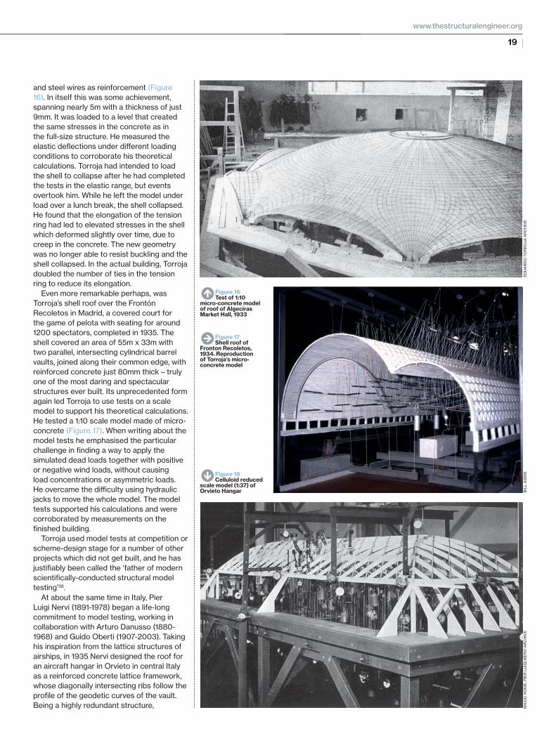
The Spanish engineer Eduardo Torroja (1899-1961) was the fi rst to fully exploit the architectural qualities of reinforced concrete shells37. His fi rst major shell roof was for the market hall at Algeciras in Spain (1933) which had a span of 47.8m, a rise of 8m and a thickness of just 90mm. During the design of the dome, which was unprecedented in its shallow rise, he needed to gain additional confi dence to supplement his calculations of stresses in the shell. He undertook tests on a one tenth scale model at the Instituto de la Construcción (ICON), which Torroja had helped to set up. The model was made of micro-concrete, using sand as the aggregate
N Figure 12Barrel vault roof using the DyWidag system for 1926 Gesolei exhibition
N Figure 14Leipzig Market model test N Figure 15
Additional 'stiff ening' rib
N Figure 13Model test of concrete shell roof for 1926 exhibition
ER
NS
T &
SO
HN
ER
NS
T &
SO
HN
ER
NS
T &
SO
HN
ER
NS
T &
SO
HN
TSE16_12-27.indd 18TSE16_12-27.indd 18 22/03/2013 13:2922/03/2013 13:29
19
and steel wires as reinforcement (Figure 16). In itself this was some achievement, spanning nearly 5m with a thickness of just 9mm. It was loaded to a level that created the same stresses in the concrete as in the full-size structure. He measured the elastic defl ections under diff erent loading conditions to corroborate his theoretical calculations. Torroja had intended to load the shell to collapse after he had completed the tests in the elastic range, but events overtook him. While he left the model under load over a lunch break, the shell collapsed. He found that the elongation of the tension ring had led to elevated stresses in the shell which deformed slightly over time, due to creep in the concrete. The new geometry was no longer able to resist buckling and the shell collapsed. In the actual building, Torroja doubled the number of ties in the tension ring to reduce its elongation.
Even more remarkable perhaps, was Torroja’s shell roof over the Frontón Recoletos in Madrid, a covered court for the game of pelota with seating for around 1200 spectators, completed in 1935. The shell covered an area of 55m x 33m with two parallel, intersecting cylindrical barrel vaults, joined along their common edge, with reinforced concrete just 80mm thick – truly one of the most daring and spectacular structures ever built. Its unprecedented form again led Torroja to use tests on a scale model to support his theoretical calculations. He tested a 1:10 scale model made of micro-concrete (Figure 17). When writing about the model tests he emphasised the particular challenge in fi nding a way to apply the simulated dead loads together with positive or negative wind loads, without causing load concentrations or asymmetric loads. He overcame the diffi culty using hydraulic jacks to move the whole model. The model tests supported his calculations and were corroborated by measurements on the fi nished building.
Torroja used model tests at competition or scheme-design stage for a number of other projects which did not get built, and he has justifi ably been called the ‘father of modern scientifi cally-conducted structural model testing’38.
At about the same time in Italy, Pier Luigi Nervi (1891-1978) began a life-long commitment to model testing, working in collaboration with Arturo Danusso (1880-1968) and Guido Oberti (1907-2003). Taking his inspiration from the lattice structures of airships, in 1935 Nervi designed the roof for an aircraft hangar in Orvieto in central Italy as a reinforced concrete lattice framework, whose diagonally intersecting ribs follow the profi le of the geodetic curves of the vault. Being a highly redundant structure,
ED
UA
RD
O T
OR
RO
JA A
RC
HIV
EB
ILL
AD
DIS
MA
XX
I, R
OM
E, P
IER
LU
IGI N
ER
VI A
RC
HIV
E
N Figure 16Test of 1:10
micro-concrete model of roof of Algeciras Market Hall, 1933
E Figure 17Shell roof of
Fronton Recoletos, 1934. Reproduction of Torroja’s micro-concrete model
S Figure 18Celluloid reduced
scale model (1:37) of Orvieto Hangar
www.thestructuralengineer.org
TSE16_12-27.indd 19TSE16_12-27.indd 19 22/03/2013 13:3022/03/2013 13:30

20 TheStructuralEngineer Feature
›
Toys that save millionsApril 2013
the theoretical analysis was both inadequate and diffi cult. Nervi approached his colleague Danusso who had founded the Laboratorio Prove Modelli e Construzioni (Laboratory for Testing Models and Structures) at the Polytechnic of Milan in 1931. Here, Danusso had begun the systematic development of materials and model testing – both for pure research and to assist the design of structures. Initially he used photoelastic stress analysis and, later, physical scale models of entire structures. Given the large size (111.5m x 44.8m) and slender lattice construction of this roof, it was not practical to build a large-scale model, at approximately 1:10, or to use micro-concrete to represent the real material. Nervi, Danusso and the young researcher Oberti, used celluloid sheet to construct a 1:37 scale model, which they tested in the elastic range of the model material (Figure 18). It was loaded with weights calculated to represent the full-scale self-weight, and weights in various distributions to simulate diff erent wind loads. Nervi continued working with Danusso and Oberti for almost 40 years39, 40, initially at the Laboratorio Prove Modelli e Construzioni and, after WWII, at ISMES – the Instituto Sperimentale Modelli e Strutture, with Oberti as Director and Danusso as President, before taking on the presidency himself41.
Wind tunnel testing of structures
The fi rst closed-loop wind tunnel was developed by at the German physicist Ludwig Prandtl (1875-1953) at Göttingen University in 1916 for testing the performance of model aerofoil sections. Aerodynamicists were already familiar
with the use of dimensionless numbers, developed and used by Froude in the 1860s for the design of ship hulls. In 1927 Otto Flachsbart (1898-1957), one of Prandtl’s co-workers, undertook the fi rst wind-tunnel experiments on buildings, to study the eff ect of the thickness of the boundary layer on wind pressures on buildings. He measured air-pressures on the walls and roof of small apartment blocks, both in isolation and adjacent to other buildings. He also studied the wind loads on the roof of a large aircraft hangar, which at times might have one side open to the wind42 (Figure 19). As well as measuring the loads on the roof, he studied the creation of vortices on the leeside of the building that could lead to high local wind speeds and increased negative pressures. For this he used a water model in which the vortices were made visible by sprinkling aluminium powder on the water surface and recorded on cine fi lm for subsequent analysis (Figure 20).
One of the fi rst buildings to be tested in a wind tunnel in the US was the Empire State Building in 1930. The air pressure was measured at several places around the circumference of the 2m high model building and at diff erent heights to determine wind loads both on the entire building and on individual windows. At this time only static loads were investigated. Periodic loads, caused by the shedding of vortices at the edges of exposed structures, were fi rst recognised during the investigation of the spectacular collapse of the Tacoma Narrows Bridge in 1940. The study of vortex shedding by buildings was fi rst investigated in the 1950s when tall towers were becoming ever more slender.
Dynamic behaviour of buildings
The fi rst model tests to investigate the behaviour of buildings in earthquakes were undertaken in Japan in 1890 by John Milne (1850-1913), an English engineering scientist who had founded the Seismological Institute of Japan in 1880. Milne and Fusakichi Omori (1868-1923), the Institute’s director, conducted the fi rst ‘shaking table’ experiments to simulate the movement of an earthquake by pulling, with ropes, the table which was constrained by springs, and suddenly letting go. This and his other work on earthquakes led to him being known as ‘Earthquake Milne’ and 'the father of seismology'. The fi rst systematic research into earthquake-resistant timber housing began in 1929 both at the Tokyo Earthquake Research Institute and by Professor Lydik Jacobsen (1897-1976) at the University of Stanford. Jacobsen recognised the need for more sophisticated models to enable the behaviour of high-rise buildings to be studied and in 1930-1931 worked with research students to undertake the fi rst shaking table model tests on a multi-storey building – a proposed building for the Olympic Club in San Francisco. This work led to the ground-breaking studies undertaken by Jacobsen and his students. The model of this 15-storey Alexander Building was much more sophisticated than the previous models, and very diffi cult to construct. Each storey had fi ve degrees of freedom to move – two horizontal, one vertical and two rotational, about horizontal axes. It was a mass of aluminium and steel plates and tubes, steel springs and steel ball bearings (Figures 21 and 22). The analysis of the results raised the understanding of the eff ects of earthquakes on high-rise buildings to a level that allowed structural engineers to consider loads due to earthquakes when designing their buildings.
Post-WWII developments in model testingImproved measurement and experimental
techniques
After the war, the use of model testing continued to grow, both in research laboratories within universities and in independent institutes such as the Laboratorio Central de Estructuras y Materiales at the School of Road Engineers in Madrid, under the direction of Torroja after its creation during the war, the ISMES in Bergamo, the LNEC (Laboratorio Nacional de Enghenaria Civil) created in Lisbon in 1946, the Cement and Concrete Association founded in 1946 at Wexham Springs near London, and Heinz Hossdorf’s Laboratorium für experimentelle Statik near Basel in Switzerland.
W Figure 19Results of Flachsbart wind tunnel tests
showing pressures on roof of aircraft hanger
N Figure 20Flachsbart water fl ow model.
Vortices created by wind fl owing over aircraft hangar roof
VD
I
VD
I
TSE16_12-27.indd 20TSE16_12-27.indd 20 22/03/2013 13:3022/03/2013 13:30

21
The most signifi cant post-war development was, perhaps, the use of dimensionless numbers in structural model testing. This had been a long time coming – Froude had used them in the 1860s, and they had been used by aerodynamicists since the 1910s. The fi rst conference proclaiming their benefi ts in structural engineering was in 195543. The use of dimensionless numbers allowed model testers to take account of scaling factors between model and full-size structure, for the various structural, material and thermal properties, even when the relationships could not be described by scientifi c equations.
The facilities and expertise established in the testing laboratories became available to any designer of unusual structures whose complexity placed them outside established precedent and beyond what could be calculated in the pre-computer era. This was especially the case in the 1950s and 1960s for large concrete shells, whose behaviour is inherently complex and was being pushed by architects towards ever more unusual and non-funicular forms. There were sometimes other obstacles: in some countries building design codes prescribed the use of statical calculations using well-established procedures and this made it diffi cult to integrate model testing into the design procedure. In Australia, largely due to the eff orts of H. J. Cowan, the design code for concrete structures was amended specifi cally to include model testing as an alternative to theoretical analysis as a means of justifying a proposed design44.
During this period the techniques of model testing continued to develop. Four diff erent types became established:
• Form-fi nding models• Elastic models at small scale (typically 1:200 to 1:50) made of a homogenous material. This was usually a plastic such as Perspex or PVC despite the viscoelastic properties of these materials• Strength models at a larger scale (typically 1:30 to 1:10) made of a material intended to model precisely the material of which the full-scale structure would be made. This was usually a model concrete made with plaster or micro-concrete using sand as the aggregate, with model reinforcement• Wind-eff ects models (typically between 300mm and 2m according to the size of wind tunnel used for the tests) made of any convenient material such as wood, plastic or plaster, since they need only achieve geometric similarity. The main constraint is fi tting the tubes measuring the air pressure over the surface of the model.
W Figure 21Scale model (1:40)
of Alexander Building in San Francisco, California
N Figure 22Alexander Building model: detail
SA
RA
H B
ILLI
NG
TO
N
SA
RA
H B
ILLI
NG
TO
N
www.thestructuralengineer.org
TSE16_12-27.indd 21TSE16_12-27.indd 21 22/03/2013 13:3122/03/2013 13:31
22 TheStructuralEngineer Feature
›
Toys that save millionsApril 2013
Making model-scale reinforced concrete for strength models became almost an art in itself. The mix design had to address both the shape and the distribution of sizes of the aggregate (actually sand) particles, since both contribute to concrete strength. Generally, normal cement was used, although some laboratories preferred gypsum. Samples of the micro-concrete had to be rigorously tested to ensure similitude with normal concrete.
Model reinforcement might vary in size from <1mm to 6mm in diameter, according to the model size. It had to match real reinforcement with regard to yield and ultimate strength, general shape of the stress-strain curve, ductility at yield, and the
nature of the bond between reinforcement and concrete. Standard wire, rod or threaded rod could be used, or plain wire deformed with a crimping machine to provide a good key between the bar and the concrete. For models that required prestressing, suitable materials for the tendons included strands of full-size twisted-strand prestressing cables, piano wire and bicycle spokes, which were useful for post-tensioning since one end is already threaded. If the model reinforcement was large enough, foil strain gauges could be attached to measure forces in the reinforcement.
As well as devising many ingenious ways of applying loads to models, the other main avenue of progress was the development of new ways of measuring strain on the surface of models, all of which were fi rst developed in the aircraft industry:
• Mechanical strain gauges became smaller, and more accurate and sensitive than those developed for the Boulder Dam tests. Moiré fringe methods were also used to enhance their sensitivity• Optical strain gauges, which use refl ected light beams to magnify small movements• Electrical resistance, wire strain gauges had been developed in the 1930s, initially for measuring stresses in static aircraft propeller blades. Foil strain gauges, using printed-circuit-board technology, were fi rst developed in the aircraft industry in 1952. They were soon adopted in structural model testing in the form of uni-axial foil gauges and the familiar rosette with three gauges at 120° or at 0°, 45° and 90°• Brittle lacquer coatings, which crack when stretched, and quickly reveal the direction and extent of strains, as well as their approximate magnitude• Photoelastic coatings used to measure surface stress over a whole area, giving a good overall picture of the fl ow of forces through a structure
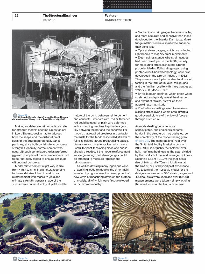
As model-testing became more sophisticated, and engineers became bolder in the structures they designed, so the complexity of the model-testing grew (Figure 23). The concrete shell roof over the Smithfi eld Poultry Market in London (1959-1961) is arguably the 'boldest' ever built – defi ning boldness as the span divided by the product of rise and average thickness. Spanning 68.6m x 39.0m the shell has a rise of 9.0m and is 75mm thick; it was at the limit of, or just beyond past experience. The testing of the 1:12 scale model for the design took 4 months. 330 strain gauges and 49 clock dials were used and over 80 000 measurements were taken – simply logging the results was at the limit of what was
N Figure 24Bundesgartenschau Multihalle, Mannheim, 1973-1974 N Figure 25
Bundesgartenschau Multihalle, interior
N Figure 231:20 model (acrylic plastic) tested by Heinz Hossdorf
during design of library roof at Basel University, 1962
BIL
L A
DD
IS
AR
UP
AR
CH
IVE
OF
FE
RN
AN
DO
CA
SS
INE
LLO
TSE16_12-27.indd 22TSE16_12-27.indd 22 22/03/2013 13:3222/03/2013 13:32
23
possible before data loggers were available45. The tests enabled the designers to:
• measure the elastic behaviour to validate the model prior to rupture• determine loads on the perimeter columns• determine deformation around the circular roof lights• verify that post-tensioning of edge beams would lift the shell off its formwork• provide a comparison with the mathematical elastic analysis• establish both the failure mode and failure load
Model testing and computers
Computerised structural analysis fi rst became available to structural engineers in the late 1960s and a number of model testers, notably Heinz Hossdorf (1925-2006)46, linked the output of strain gauges to computers to perform hybrid analyses which fed real data into analysis software to provide an improved overall modelling process.
By the mid-1970s computer-based modelling was well on the way to replacing the need for physical model testing. However, its contribution to the development and refi nement of analytical methods should not be overlooked. A fi nal case study, the Mannheim Bundesgartenschau (1973-1974) illustrates the degree of sophistication that physical model-testing achieved, combining several model tests with diff erent purposes, and a computer analysis that was at the limit of what was possible at the time. Within a few years, computer modelling became suffi ciently quick, accurate and reliable to serve the designer’s needs. The use of model testing declined quickly from the mid-1970s.
Bundesgartenschau Multihalle,
Mannheim, 1973-1974
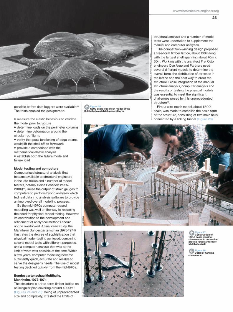
The structure is a free-form timber-lattice on an irregular plan covering around 4000m2 (Figures 24 and 25). Being of unprecedented size and complexity, it tested the limits of
structural analysis and a number of model tests were undertaken to supplement the manual and computer analyses.
The competition-winning design proposed a free-form timber lattice, about 160m long with the largest shell spanning about 70m x 60m. Working with the architect Frei Otto, engineers Ove Arup and Partners used several diff erent models to determine the overall form, the distribution of stresses in the lattice and the best way to erect the structure. Close integration of the manual structural analysis, computer analysis and the results of testing the physical models was essential to meet the signifi cant challenges posed by this unprecedented structure47.
First a wire-mesh model, about 1:300 scale, was made to establish the basic form of the structure, consisting of two main halls connected by a linking tunnel (Figure 26).
N Figure 27Construction of
1:98.9 scale hanging-chain model to determine precise funicular form of Multihalle shell
N Figure 261:300 scale wire mesh model of the
Multihalle to establish general form
W Figure 28Detail of hanging-
chain model
INS
TIT
UT
E F
OR
LIG
HT
WE
IGH
T S
TR
UC
TU
RE
S, S
TU
TT
GA
RT
IAN
LID
DE
LLIA
N L
IDD
ELL
www.thestructuralengineer.org
TSE16_12-27.indd 23TSE16_12-27.indd 23 22/03/2013 13:3322/03/2013 13:33
24 TheStructuralEngineer Feature
›
Toys that save millionsApril 2013
to compare the results from the tests on the Essen model and the behaviour of the real Essen shell. This established that the relationship between the model collapse load and full-size collapse load was in proportion to the value of the dimensionless number E.Ixx/a.S3 for model and prototype, where:
E is the modulus of the materialIxx is the section modulus a is the spacing between laths, and S is the span of the dome
These results demonstrated the benefi t of the diagonal cables in inhibiting overall buckling, and also indicated that a double-layer lattice would be needed for the larger Mannheim shell.
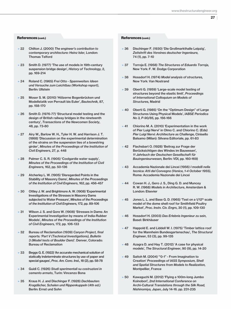
Based on the experience of the Essen model, a 1:60 scale model of the main shell of the Mannheim building was constructed in the same manner, using Perspex laths 1.4mm x 2.6mm, at 50mm spacing (Figure 32). The 1m wide model was tested in the same manner as the Essen shell, applying the load using bundles of 100mm nails, each weighing 12.5gm. Defl ections of the lattice were measured using dial gauges, later refi ned by using wires and a lever arrangement to avoid the inevitable friction when a gauge touches the structure. The results were used to validate the results of the computer model and to provide a physical understanding of the nature of the buckling failures in the lattice, as well as the location of critical areas in this complex three-dimensional structure.
One fi nal model of the Multihalle was made when the designers became concerned about the severe local bending that would be introduced by the contractor’s proposed method of erecting the lattice using cranes. A 1:60 scale model was made from woven wire mesh and used to
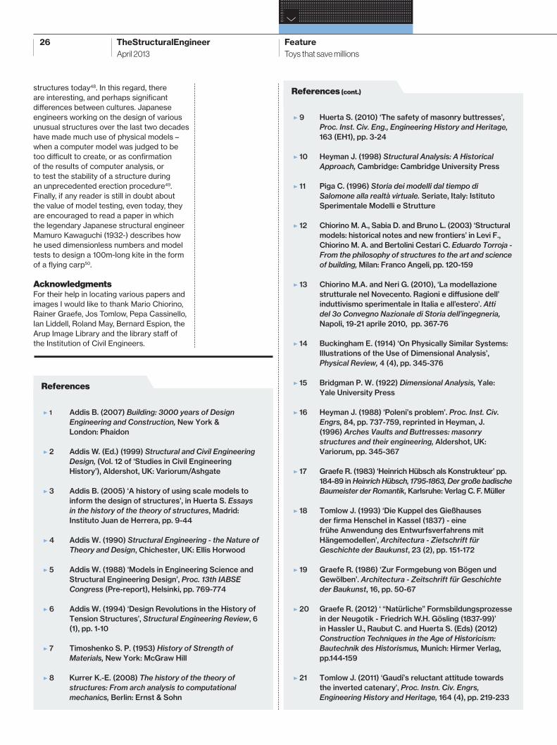
essential to test an elastic structural model. However, there was also no precedent for making and testing such a model. It was decided that a model of a similar, smaller lattice dome that Frei Otto had previously constructed for the German Building Exhibition at Essen in 1962 would be built and tested. This would give a better understanding of the behaviour of a lattice dome, and would test the suitability of the model material and the proposed method of constructing the model, as well as determining the accuracy with which the model was able to replicate the behaviour of the full-size structure. A 1:16 scale model was constructed using laths of 3mm x 1.7mm, at 50mm centres, made of Perspex with a modulus one quarter that of timber (Figure 31). It was loaded with a uniformly distributed load, on which was superimposed an increasing point load to initiate a local buckling failure. This was repeated with higher UDLs and thus the critical UDL was determined. Four versions of the model were tested – with pinned and rigid (glued) joints between the laths, and with and without diagonal ties. Dimensional analysis was used
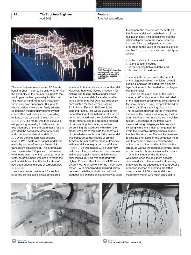
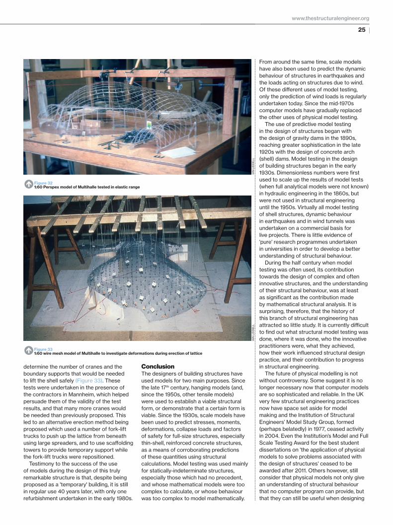
This enabled a more accurate 1:98.9 scale, hanging-chain model to be built to determine the geometry of the boundary supports that would give the best geometry for the roof. The mesh of hand-made wire links, each 15mm long, was hung from 80 supports whose positions were then fi nely adjusted to establish the boundary geometry that created the best funicular form, avoiding regions of low tension in the net (Figures 27 and 28). The model was then surveyed using photogrammetry to determine the true geometry of the shell, and these results provided the coordinate data for manual and computer analytical models (Figure 29). Once the fi nal form was decided upon, a 1:200 scale wind-tunnel model was made, by vacuum-forming a 2mm-thick, transparent plastic sheet. The air pressure was measured at 150 places to determine wind loads over the entire roof area. In other tests, paraffi n smoke was used to make the airfl ow visible and identify the location of fl ow separation and areas of turbulent fl ow (Figure 30).
As there was no precedent for such a structure on this scale, it was considered
N Figure 301:200 scale Perspex wind-tunnel model
W Figure 29Completed hanging-
chain model - surveyed using photogrammetry to determine precise geometry
N Figure 31Perspex model of Essen lattice shell
IAN
LID
DE
LL
IAN
LID
DE
LL
AR
UP
TSE16_12-27.indd 24TSE16_12-27.indd 24 22/03/2013 13:3322/03/2013 13:33
25
From around the same time, scale models have also been used to predict the dynamic behaviour of structures in earthquakes and the loads acting on structures due to wind. Of these diff erent uses of model testing, only the prediction of wind loads is regularly undertaken today. Since the mid-1970s computer models have gradually replaced the other uses of physical model testing.
The use of predictive model testing in the design of structures began with the design of gravity dams in the 1890s, reaching greater sophistication in the late 1920s with the design of concrete arch (shell) dams. Model testing in the design of building structures began in the early 1930s. Dimensionless numbers were fi rst used to scale up the results of model tests (when full analytical models were not known) in hydraulic engineering in the 1860s, but were not used in structural engineering until the 1950s. Virtually all model testing of shell structures, dynamic behaviour in earthquakes and in wind tunnels was undertaken on a commercial basis for live projects. There is little evidence of 'pure' research programmes undertaken in universities in order to develop a better understanding of structural behaviour.
During the half century when model testing was often used, its contribution towards the design of complex and often innovative structures, and the understanding of their structural behaviour, was at least as signifi cant as the contribution made by mathematical structural analysis. It is surprising, therefore, that the history of this branch of structural engineering has attracted so little study. It is currently diffi cult to fi nd out what structural model testing was done, where it was done, who the innovative practitioners were, what they achieved, how their work infl uenced structural design practice, and their contribution to progress in structural engineering.
The future of physical modelling is not without controversy. Some suggest it is no longer necessary now that computer models are so sophisticated and reliable. In the UK very few structural engineering practices now have space set aside for model making and the Institution of Structural Engineers’ Model Study Group, formed (perhaps belatedly) in 1977, ceased activity in 2004. Even the Institution’s Model and Full Scale Testing Award for the best student dissertations on 'the application of physical models to solve problems associated with the design of structures' ceased to be awarded after 2011. Others however, still consider that physical models not only give an understanding of structural behaviour that no computer program can provide, but that they can still be useful when designing
ConclusionThe designers of building structures have used models for two main purposes. Since the late 17th century, hanging models (and, since the 1950s, other tensile models) were used to establish a viable structural form, or demonstrate that a certain form is viable. Since the 1930s, scale models have been used to predict stresses, moments, deformations, collapse loads and factors of safety for full-size structures, especially thin-shell, reinforced concrete structures, as a means of corroborating predictions of these quantities using structural calculations. Model testing was used mainly for statically-indeterminate structures, especially those which had no precedent, and whose mathematical models were too complex to calculate, or whose behaviour was too complex to model mathematically.
determine the number of cranes and the boundary supports that would be needed to lift the shell safely (Figure 33). These tests were undertaken in the presence of the contractors in Mannheim, which helped persuade them of the validity of the test results, and that many more cranes would be needed than previously proposed. This led to an alternative erection method being proposed which used a number of fork-lift trucks to push up the lattice from beneath using large spreaders, and to use scaff olding towers to provide temporary support while the fork-lift trucks were repositioned.
Testimony to the success of the use of models during the design of this truly remarkable structure is that, despite being proposed as a 'temporary' building, it is still in regular use 40 years later, with only one refurbishment undertaken in the early 1980s.
N Figure 321:60 Perspex model of Multihalle tested in elastic range
N Figure 331:60 wire mesh model of Multihalle to investigate deformations during erection of lattice
IAN
LID
DE
LLIA
N L
IDD
ELL
www.thestructuralengineer.org
TSE16_12-27.indd 25TSE16_12-27.indd 25 22/03/2013 13:3322/03/2013 13:33
26 TheStructuralEngineer Feature
›
Toys that save millionsApril 2013
E 9 Huerta S. (2010) ‘The safety of masonry buttresses’,
Proc. Inst. Civ. Eng., Engineering History and Heritage,
163 (EH1), pp. 3-24
E 10 Heyman J. (1998) Structural Analysis: A Historical
Approach, Cambridge: Cambridge University Press
E 11 Piga C. (1996) Storia dei modelli dal tiempo di
Salomone alla realtà virtuale. Seriate, Italy: Istituto
Sperimentale Modelli e Strutture
E 12 Chiorino M. A., Sabia D. and Bruno L. (2003) ‘Structural
models: historical notes and new frontiers’ in Levi F.,
Chiorino M. A. and Bertolini Cestari C. Eduardo Torroja -
From the philosophy of structures to the art and science
of building, Milan: Franco Angeli, pp. 120-159
E 13 Chiorino M.A. and Neri G. (2010), ‘La modellazione
strutturale nel Novecento. Ragioni e diff usione dell’
induttivismo sperimentale in Italia e all’estero’. Atti
del 3o Convegno Nazionale di Storia dell’ingegneria,
Napoli, 19-21 aprile 2010, pp. 367-76
E 14 Buckingham E. (1914) ‘On Physically Similar Systems:
Illustrations of the Use of Dimensional Analysis’,
Physical Review, 4 (4), pp. 345-376
E 15 Bridgman P. W. (1922) Dimensional Analysis, Yale:
Yale University Press
E 16 Heyman J. (1988) ‘Poleni’s problem’. Proc. Inst. Civ.
Engrs, 84, pp. 737-759, reprinted in Heyman, J.
(1996) Arches Vaults and Buttresses: masonry
structures and their engineering, Aldershot, UK:
Variorum, pp. 345-367
E 17 Graefe R. (1983) ‘Heinrich Hübsch als Konstrukteur’ pp.
184-89 in Heinrich Hübsch, 1795-1863, Der große badische
Baumeister der Romantik, Karlsruhe: Verlag C. F. Müller
E 18 Tomlow J. (1993) ‘Die Kuppel des Gießhauses
der fi rma Henschel in Kassel (1837) - eine
frühe Anwendung des Entwurfsverfahrens mit
Hängemodellen’, Architectura - Zietschrift für
Geschichte der Baukunst, 23 (2), pp. 151-172
E 19 Graefe R. (1986) ‘Zur Formgebung von Bögen und
Gewölben’. Architectura - Zeitschrift für Geschichte
der Baukunst, 16, pp. 50-67
E 20 Graefe R. (2012) ‘ “Natürliche” Formsbildungsprozesse
in der Neugotik - Friedrich W.H. Gösling (1837-99)’
in Hassler U., Raubut C. and Huerta S. (Eds) (2012)
Construction Techniques in the Age of Historicism:
Bautechnik des Historismus, Munich: Hirmer Verlag,
pp.144-159
E 21 Tomlow J. (2011) ‘Gaudí’s reluctant attitude towards
the inverted catenary’, Proc. Instn. Civ. Engrs,
Engineering History and Heritage, 164 (4), pp. 219-233
References (cont.)
E 1 Addis B. (2007) Building: 3000 years of Design
Engineering and Construction, New York &
London: Phaidon
E 2 Addis W. (Ed.) (1999) Structural and Civil Engineering
Design, (Vol. 12 of ‘Studies in Civil Engineering
History’), Aldershot, UK: Variorum/Ashgate
E 3 Addis B. (2005) ‘A history of using scale models to
inform the design of structures’, in Huerta S. Essays
in the history of the theory of structures, Madrid:
Instituto Juan de Herrera, pp. 9-44
E 4 Addis W. (1990) Structural Engineering - the Nature of
Theory and Design, Chichester, UK: Ellis Horwood
E 5 Addis W. (1988) ‘Models in Engineering Science and
Structural Engineering Design’, Proc. 13th IABSE
Congress (Pre-report), Helsinki, pp. 769-774
E 6 Addis W. (1994) ‘Design Revolutions in the History of
Tension Structures’, Structural Engineering Review, 6
(1), pp. 1-10
E 7 Timoshenko S. P. (1953) History of Strength of
Materials, New York: McGraw Hill
E 8 Kurrer K.-E. (2008) The history of the theory of
structures: From arch analysis to computational
mechanics, Berlin: Ernst & Sohn
References
structures today48. In this regard, there are interesting, and perhaps signifi cant diff erences between cultures. Japanese engineers working on the design of various unusual structures over the last two decades have made much use of physical models – when a computer model was judged to be too diffi cult to create, or as confi rmation of the results of computer analysis, or to test the stability of a structure during an unprecedented erection procedure49. Finally, if any reader is still in doubt about the value of model testing, even today, they are encouraged to read a paper in which the legendary Japanese structural engineer Mamuro Kawaguchi (1932-) describes how he used dimensionless numbers and model tests to design a 100m-long kite in the form of a fl ying carp50.
AcknowledgmentsFor their help in locating various papers and images I would like to thank Mario Chiorino, Rainer Graefe, Jos Tomlow, Pepa Cassinello, Ian Liddell, Roland May, Bernard Espion, the Arup Image Library and the library staff of the Institution of Civil Engineers.
TSE16_12-27.indd 26TSE16_12-27.indd 26 22/03/2013 13:3422/03/2013 13:34
27
E 22 Chilton J. (2000) The engineer’s contribution to
contemporary architecture: Heinz Isler, London:
Thomas Telford
E 23 Smith D. (1977) ‘The use of models in 19th-century
suspension bridge design’, History of Technology, 2,
pp. 169-214
E 24 Roland C. (1965) Frei Otto - Spannweiten: Ideen
und Versuche zum Leichtbau (Workshop report),
Berlin: Ullstein
E 25 Moser S. M. (2010) ‘Hölzerne Bogenbrücken und
Modellstatik von Perrault bis Euler’, Bautechnik, 87,
pp. 158-170
E 26 Smith D. (1976-77) ‘Structural model testing and the
design of British railway bridges in the nineteenth
century’, Transactions of the Newcomen Society,
48, pp. 73-80
E 27 Airy W., Barlow W. H., Tyler H. W. and Harrison J. T.
(1868) ‘Discussion on the experimental determination
of the strains on the suspension ties of a bowstring
girder’, Minutes of the Proceedings of the Institution of
Civil Engineers, 27, p. 448
E 28 Palmer C. S. R. (1905) ‘Coolgardie water supply’,
Minutes of the Proceedings of the Institution of Civil
Engineers, 162, pp. 50-136
E 29 Atcherley L. W. (1905) ‘Disregarded Points in the
Stability of Masonry Dams’, Minutes of the Proceedings
of the Institution of Civil Engineers, 162, pp. 456-457
E 30 Ottley J. W. and Brightmore A. W. (1908) ‘Experimental
Investigations of the Stresses in Masonry Dams
subjected to Water Pressure’, Minutes of the Proceedings
of the Institution of Civil Engineers, 172, pp. 89-106
E 31 Wilson J. S. and Gore W. (1908) ‘Stresses in Dams: An
Experimental Investigation by means of India-Rubber
Models’, Minutes of the Proceedings of the Institution
of Civil Engineers, 172, pp. 106-133
E 32 Bureau of Reclamation (1939) Canyon Project, fi nal
reports: ‘Part V (Technical Investigations), Bulletin
3 (Model tests of Boulder Dam)’. Denver, Colorado:
Bureau of Reclamation
E 33 Beggs G. E. (1922) ‘An accurate mechanical solution of
statically indeterminate structures by use of paper and
special gauges’, Proc. Am. Conc. Inst., 18 (2), pp. 58-78
E 34 Guidi C. (1926) Studi sperimentali su costruzioni in
cemento armato, Turin: Vincenzo Bona
E 35 Kraus H. J. and Dischinger F. (1928) Dachbauten:
Kragdächer, Schalen und Rippenkuppeln (4th ed.)
Berlin: Ernst und Sohn
E 36 Dischinger F. (1930) ‘Die Großmarkthalle Leipzig’,
Zeitshrift des Vereines deutscher Ingenieure,
74 (1), pp. 7-10
E 37 Torroja E. (1958) The Structures of Eduardo Torroja,
New York: F. W. Dodge Corporation
E 38 Hossdorf H. (1974) Model analysis of structures,
New York: Van Nostrand
E 39 Oberti G. (1959) ‘Large-scale model testing of
structures beyond the elastic limit’, Proceedings
of International Colloquium on Models of
Structures, Madrid
E 40 Oberti G. (1985) ‘On the “Optimum Design” of Large
Structures Using Physical Models’, IABSE Periodica
No 3, P-90/85, pp. 156-166
E 41 Chiorino M. A. (2010) ‘Experimentation in the work
of Pier Luigi Nervi’ in Olmo C. and Chiorino C. (Eds)
Pier Luigi Nervi: Architecture as Challenge, Cinisello
Balsamo (Milan): Silvana Editoriale, pp. 61-83
E 42 Flachsbart O. (1928) ‘Beitrag zur Frage der
Berücksichtigen des Windes im Bauwesen’,
11 Jahrbuch der Deutschen Gesellschaft für
Bauingenieurwesen, Berlin: VDI, pp. 160-169)
E 43 Accademia Nazionale dei Lincei (1956) I modelli nella
tecnica: Atti del Convegno (Venice, 1-4 October 1955),
Rome: Accademia Nazionale dei Lincei
E 44 Cowan H. J., Gero J. S., Ding G. D. and Muncey
R. W. (1968) Models in Architecture, Amsterdam &
London: Elsevier
E 45 Jones L. L. and Base G. D. (1965) ‘Test on a 1/12th scale
model of the dome shell roof for Smithfi eld Poultry
Market’, Proc. Instn. Civ. Engrs, 30 (1), pp. 109-130
E 46 Hossdorf H. (2003) Das Erlebnis Ingenieur zu sein,
Basel: Birkhäuser
E 47 Happold E. and Liddell W. I. (1975) ‘Timber lattice roof
for the Mannheim Bundesgartenschau’, The Structural
Engineer, 53 (3), pp. 99-135
E 48 Azagra D. and Hay T. (2012) ‘A case for physical
models’, The Structural Engineer, 90 (9), pp. 14-20
E 49 Saitoh M. (2004) ‘“0-1” - From Imagination to
Creation’ Proceedings of IASS Symposium, Shell
and Spatial Structures from Models to Realization,
Montpellier, France
E 50 Kawaguchi M. (2012) ‘Flying a 100m-long Jumbo
Koinobori’, 2nd International Conference on
Archi-Cultural Translations through the Silk Road,
Nishinomiya, Japan, July 14-16. pp. 231-235
References (cont.) References (cont.)
www.thestructuralengineer.org
TSE16_12-27.indd 27TSE16_12-27.indd 27 22/03/2013 13:3422/03/2013 13:34