toward learning and understanding electricity:...
TRANSCRIPT

Wainwright: Toward Learning and Understanding Electricity 1
Toward Learning and Understanding Electricity:
Challenging Persistent Misconceptions
Dr. Camille L. Wainwright, Pacific University 2043 College Way, Forest Grove, OR 97116 503.352.2963 (Office); 503.352.2907 (Fax)
[email protected] http://fg.ed.pacificu.edu/wainwright/index.html
I. Statement of the Problem When students enter physics, electronics or engineering courses, they arrive with many notions about the physical world in general and electricity specifically. These ideas may be a result of previous experience, everyday language, or prior study, and they may agree with the explanations provided by experts. But too often, the preconceptions or alternative conceptions are misconceptions that have resulted from “common sense” explanations, instruction by teachers, or language lacking precision or accuracy. Once misconceptions are embedded, it is clear that they are persistent, comforting, and highly resistant to change. (Clement, 1987) On the other hand, some of the intuitive ideas students bring with them can be used to scaffold further knowledge through experience. For example, students quickly conclude that ‘something is moving in the wires’ when they close a switch and a bulb lights simultaneously. (Duit, Jung & Rhoneck, 1985) They also readily agree that bulbs are giving off energy when they are lit, and they are not giving off energy when they are disconnected. And they sense that a battery or a wall outlet is a source of energy; this apparently arises because they are often reminded to turn off a light or appliance (that is plugged in) as a means of saving energy. (Multiple terms have been assigned to the learner’s conceptions, including preconceptions, alternative frameworks, naïve conceptions, and alternative conceptions. While authors would argue for fundamental differences among these constructs, this article will use the generic term ‘misconception’ to designate any student conception that is not in agreement with expert scientific explanations and which leads therefore to a systematic pattern of errors in problem-solving. Science educators often describe the construction of conceptual knowledge among their students as a process of moving from their naïve conceptions to those concepts accepted by the scientific community. But it is clear from a myriad of research over time and among schools internationally that schooling does not bring all – or even many – students to the development of a scientific understanding consistent with accepted science (Chi, Slotta & de Leeuw, 1994; Driver, R., Guesne & Tiberghien, 1985). Many studies, papers, and conferences have focused on the conceptual understanding and misconceptions that arise around the learning of electricity in simple circuits. (Duit, etal, 1985) “The emerging picture world-wide is not promising, given that an adequate knowledge of . . . electrical circuits has rarely been acquired by students by the end of secondary education.” (Psillos, 1997) II. Purpose The purpose of this paper is to:
• Review the published literature on misconceptions in introductory electricity concepts using simple DC circuits
• Identify areas of electricity misconceptions not previously cited • Indicate possible explanations for the origin of these misconceptions • Consider teaching strategies that have proven successful in challenging these
misconceptions
Wainwright: Toward Learning and Understanding Electricity 2
III. Literature Review The misconceptions surrounding current electricity are universal, resistant to change, and even perpetuated by teachers, textbooks, and common experience. (Duit et al, 1985; Shipstone, 1988) Cohen, Eylon, Ganiel (1983) identified prevalent naïve conceptions surrounding potential difference and current in simple circuits. Raduta (1998) has provided a thorough overview of misconceptions related to electromagnetism including electric snf magnetic fields. Duit, Jung and von Rhoneck have identified common misconceptions within students’ ideas about elementary circuits in the following categories: Consumption of Current; Local Reasoning; Voltage in Closed Circuits; Sequential Reasoning; Resistance. (Duit, et al, 1985). In addition to these categories, Steinberg has added Battery Origin and Battery Agency as additional areas in which common student misconceptions are found. (Steinberg et al, 2005). Osborne (1983) identified the naïve notions of non-recursive current, current consumption and clashing current in circuits. Shipstone has demonstrated that these common misconceptions are international and universal. (Shipstone, 1988) Common misconceptions identified in the literature:
1. Consumption of current: It is intuitive for students to think that current is consumed because charge is ‘used up’. After all, they commonly hear that a ‘dead’ battery must be ‘re-charged’; therefore it must have become ‘empty’.
2. Local Reasoning: This phenomenon occurs when students focus on what is occurring at only one point within the circuit without considering the circuit as an interrelated system. A student may assume, for example, that once current reaches a junction, it must divide equally into each branch.
3. Voltage in Closed Circuits: Even after instruction students use the voltage concept as having approximately the same properties as the current concept. They tend to think of a battery as a source of constant current rather than a source of constant voltage.
4. Sequential Reasoning: Assuming that what occurs ‘downstream’ in the circuit cannot affect ‘upstream’ components of the circuit, again failing to recognize the circuit as a system.
5. Resistance: Some students have difficulty understanding the effect of changing resistance in a circuit, considering the battery to be a constant current source. Most students have difficulty with the inverse/non-additive effect of resistors in parallel.
6. Battery Origin: Many students assume that the battery is the source of mobile charge (current) in a circuit – that charges are pumped out of a supply within the battery rather than recycled.
7. Battery Agency: A belief that without a battery in a circuit no current can flow. 8. Clashing Currents: An assumption that current must be released from both ends of a battery, and
that bulbs light when current moves through them in both directions. For example, many students believe a single bulb will light if connected to a cell with one wire; adding a second wire just supplies it with more current.
IV. Design/Methodology In order to prepare high school students to meet the MCAS Technology Standards for Massachusetts students (www.doe.mass.edu/frameworks/current.html), the Boston Museum of Science has undertaken the development of a year-long curriculum – Engineering the Future. In this introductory engineering class, students learn both scientific concepts and design technology; activities challenge them to apply scientific knowledge within an engineering context. During a complete school year, students study, experiment and experience design-under-constraint challenges within the following four units:
Unit 1: Engineering Design and Manufacturing Unit 2: Construction and Integrated Systems
Wainwright: Toward Learning and Understanding Electricity 3
Unit 3: Fluid and Thermal Systems Unit 4: Electricity and Communication
The author collaborated with the Museum staff in developing the “Electricity and Communication” curriculum unit as well as assessment procedures. The lessons on electricity were modeled after the curriculum “Capacitor-Aided System for Teaching and Learning Electricity” (CASTLE). Identical 15-item pre- and post-assessment instruments were carefully aligned with the objectives of the circuit electricity section of Unit 4. Each item was accompanied by a Likert-scale indication of their level of confidence regarding the correctness of their answer. Fifty-four students in two Engineering the Future classes, taught by two different teachers (one male, one female) had each been given a paper-and-pencil pre-assessment prior to four weeks of instruction on simple DC circuits, and followed by an identical post-assessment. During instruction, the focus was on the scientific foundations of electricity, but some engineering challenges were interspersed as well. (Examples: design a two-speed fan, design a burglar alarm system.) In addition, clinical interviews of seven randomly selected students from two different class sections were conducted, based on the post-assessment as the interview protocol (See Appendix A). Students were asked to think aloud as they considered each assessment item, selected an answer, explained their reasoning, and indicated their level of confidence. The researcher attempted to ask neutral non-leading questions, provided a comfortable context in which students felt free to express their thinking, and avoided cues for the accepted answer. (Bell, 1985) Interviews were audio-taped and transcribed. Quotes will be provided in the following section to demonstrate each of the common electricity misconceptions cited below. V. Results A. Clinical Interviews: Interview excerpts are provided in order to support and define an expanded list of previously-described misconceptions in simple electrical circuits. While these are generally similar to those reported by others in the literature, some variations and extensions are described. All student quotes are taken directly from the clinical interviews in response to the post-assessment items used as the interview protocol following approximately five weeks of instruction. Student interview quotes reveal the following as prevalent issues:
a. Understanding the role of the battery as a source of energy but not a supplier of charge b. Recognizing the relationship between energy and charge within a circuit c. Errors due to sequential reasoning d. Resistance of an individual circuit component (local reasoning) e. Net resistance of series vs. parallel resistors f. Understanding of the circuit as a system g. Lack of knowledge of internal structure of a bulb h. Understanding the role of a compass in circuit analysis i. Incorrect vocabulary j. Capacitor charging and discharging k. Circuit analysis via color-coding l. The function of ammeters and voltmeters
Note that in some cases a single quote identifies more than one of the issues cited above. Following a quote the assessment item number is identified.
Wainwright: Toward Learning and Understanding Electricity 4
a. Understanding the role of the battery as a source of energy but not a supplier of charge Many students believe that the battery is the source of electricity, which they usually mean as the source of current or charges moving through the circuit; they do not tend to recognize that charges already exist in the wires and in all circuit components while the battery is not the source of charge but the source of energy which causes the charge to move. Question #4 on the assessment asked “What is the origin of the moving charges in a circuit?” Student P: “Charges in the circuit I believe start at the batteries.” Interviewer: “How do you happen to know that’s the case?” Student P: “Basically just growing up. The battery is where the energy is. If you actually put your tongue on a battery it hurts, so I figure that is where the electricity comes from. I would say I am confident.” (#4) Student Q: “What is the origin of the moving charges? I am pretty sure it is the power source, because the wires don’t have any charges themselves, so it couldn’t be the wires. The bulbs don’t have any power themselves. It has to be the battery. I’m sure I’m right. (#4) Students Y: Because the battery is going to give off the energy, the energy through the wires so the bulbs can light up. So it is batteries. I’m confident. (#4) b. Recognizing the relationship between energy and charge Many students do not understand that charge is continually recycled within the circuit while energy is required to push/pull it around that circuit, and that the stored energy in the battery (but not charge) may be transformed to light and heat energy. They do not perceive that current is a consequence of electric pressure difference (potential difference). The following student does not know how to differentiate between energy and charge flow; he is also unaware of alternating current. Interviewer: “#10: When paying a household electric bill, what does one actually pay for? Student Q: You are paying kilowatt-hours, which is the current flow, current consisting of charges moving in one direction. I think it is based on current, so C. (#10) Question #12 asks: “Are charges used up in the production of light in a light bulb?” Student P. “Yes, the charge is used up, because it is converted to heat and light, but I guess you could also say it is conserved if you are considering heat and light as part of the entire system.” Interviewer: “What does conserved mean?” Student P: “Conserved is that it is not created or destroyed.” Interviewer: “Did you do any experiment or any activity or any demonstration in class that helps with that question?” Student P: “For the conservation of electric charge?” Interviewer: “Yes.” Student P: “Not that I remember. I think D means that if it is converted to heat and light, it is then changed back into energy going to the bottom of the battery. I think the way it is asking the question actually means that the charge is used up, because it is converted to heat and light, so I am somewhat confident.” (#12) Student Y: “Yes, because if you ever touch a bulb that has been on for awhile, it is going to burn a little, and be hot. So the charge is moving around and then it converts to heat and then to light. (#12.) Student Z: When they say charges it reminds me that energy can never be created or destroyed. I remember that from my biology class. I am guessing the charge can’t be used up, but again energy gets used up in like
Wainwright: Toward Learning and Understanding Electricity 5
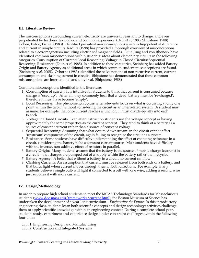
houses. My mom always says don’t waste energy, or whatever, so I am guessing it is not getting used up, but changes into heat, so I am in the guessing area, and somewhat confident. (#12) Student Q: “I am going to say charge is used up, charges moving through the filament, because if charges weren’t used up, the battery would last forever.” (#12) Student W: “I definitely think my answer would move toward the yes side, because I don’t believe that if charges weren’t used up, then we wouldn’t be paying for it, especially when we use lights. You know what I mean? If it was recycled, then it wouldn’t matter how much we used in lights. Actually, for instance, I went to change my light bulbs last night and I burned my hand. I would be leaning more toward converting to heat and light when the charge is put in, so I think it is A. I am somewhat confident.” (#12) c. Errors due to sequential reasoning Many students are confident that the amount of current flowing in components of a circuit is dependent on which one comes ‘first’. Item #5. Both Figures 1 and 2 below represent the initial moments of charging a capacitor. Which of the following statements is correct?
(A) The electric current in Figure 1 is greater through Bulb A than Bulb B.
(B) The electric current in Figure 1 is
greater through Bulb B than Bulb A.
(C) The electric current in Figure 2 is greater through Bulb A than Bulb B.
(D) The electric current is the same through Figure 1 Figure 2 Bulb A in both circuits, but not Bulb B.
(E) The electrical current is the same through all four bulbs.
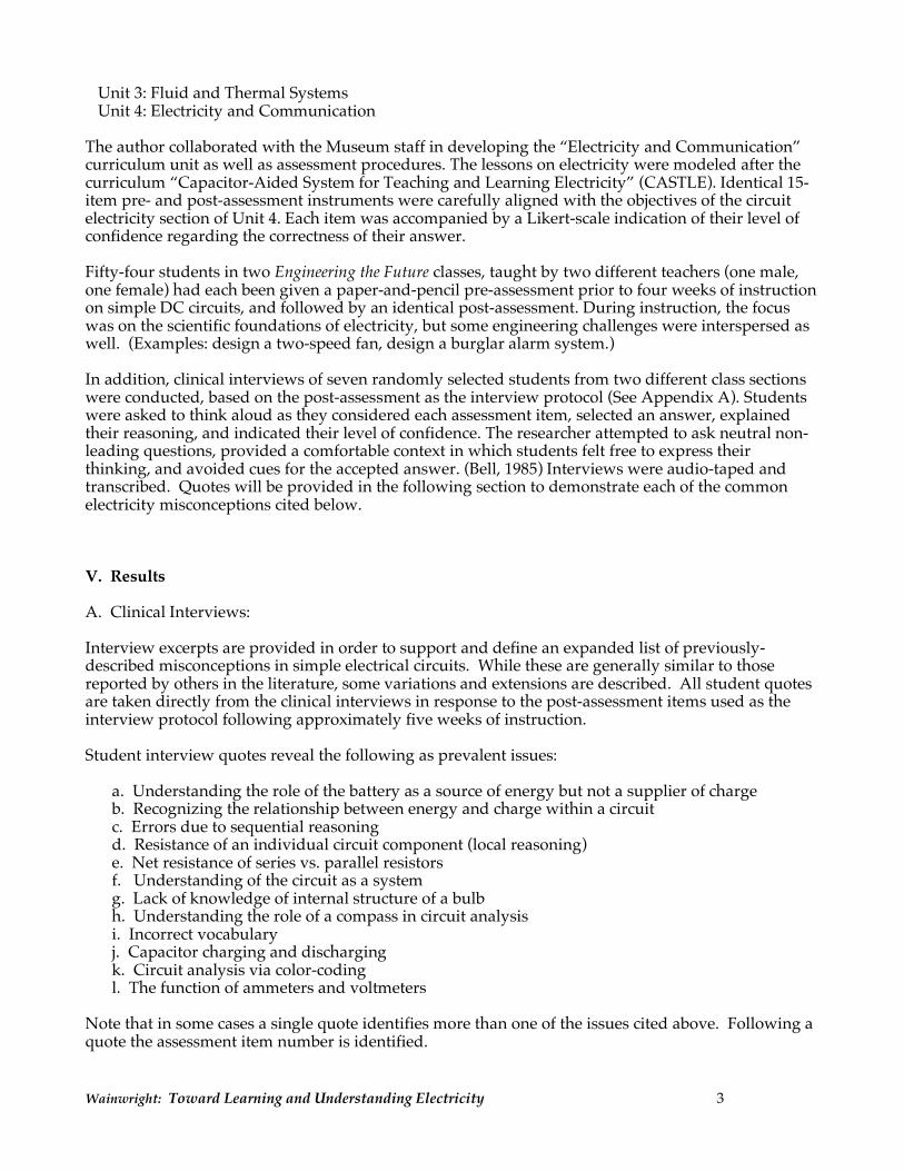
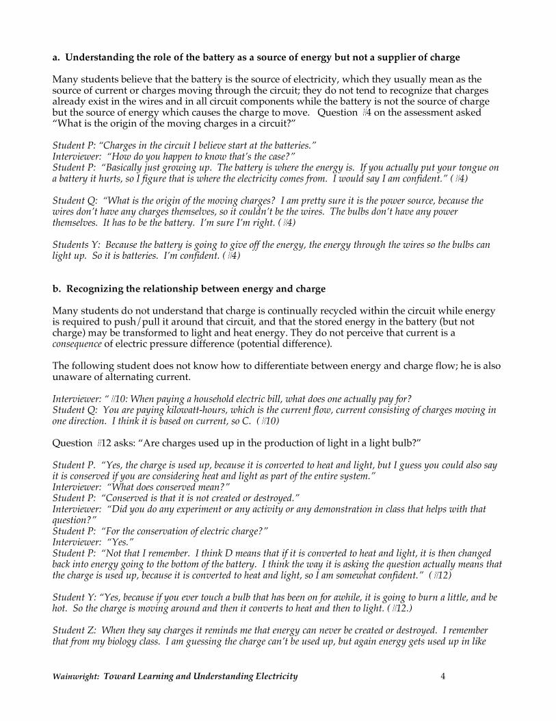
Student R: “I remember that if this was like a motor or something, not a capacitor, I know that this would be greater, because it comes out of plus and goes to minus, it hits this first.” (#5) Student W: “Regarding the position, just looking at the pictures, the bulbs are both the same distance, the same position from the source, and here Bulb A is closer to the source of power. I figure that when the current goes through there it won’t be as great going to B. So I think it was C, yes.” (#5) Some students also believe that the length of wire ‘before’ the component has an effect on the magnitude of current flow. The next quote is in reference to the diagram for Question #6 (at right). Student R: “I am going to say that bulb A is the same brightness in both circuits. I am confident, because it goes through here, and it has equal wire in length to go through. There are no resistors in the way. It is going to hit A the same way both times.” (#6)
A
B - +
A B - +
C B
A A
B - +
- +
Wainwright: Toward Learning and Understanding Electricity 6
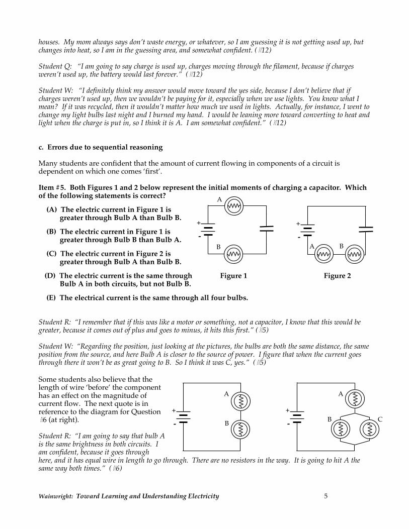
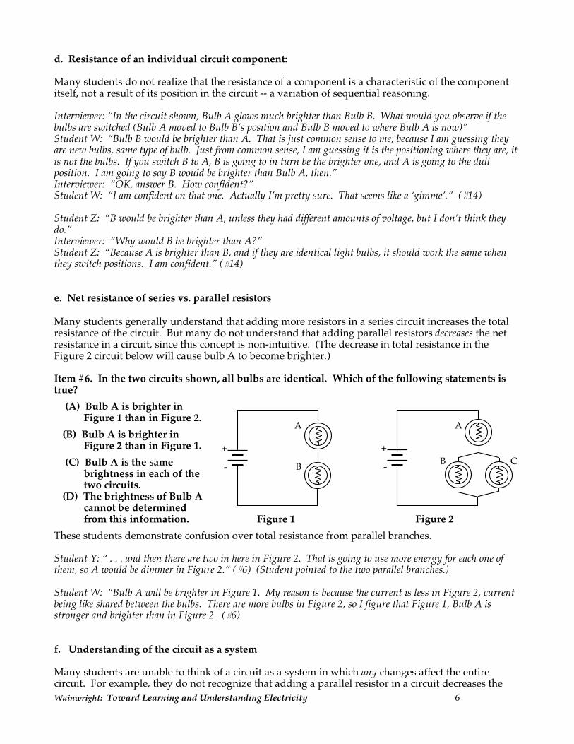
d. Resistance of an individual circuit component: Many students do not realize that the resistance of a component is a characteristic of the component itself, not a result of its position in the circuit -- a variation of sequential reasoning. Interviewer: “In the circuit shown, Bulb A glows much brighter than Bulb B. What would you observe if the bulbs are switched (Bulb A moved to Bulb B’s position and Bulb B moved to where Bulb A is now)” Student W: “Bulb B would be brighter than A. That is just common sense to me, because I am guessing they are new bulbs, same type of bulb. Just from common sense, I am guessing it is the positioning where they are, it is not the bulbs. If you switch B to A, B is going to in turn be the brighter one, and A is going to the dull position. I am going to say B would be brighter than Bulb A, then.” Interviewer: “OK, answer B. How confident?” Student W: “I am confident on that one. Actually I’m pretty sure. That seems like a ‘gimme’.” (#14) Student Z: “B would be brighter than A, unless they had different amounts of voltage, but I don’t think they do.” Interviewer: “Why would B be brighter than A?” Student Z: “Because A is brighter than B, and if they are identical light bulbs, it should work the same when they switch positions. I am confident.” (#14) e. Net resistance of series vs. parallel resistors Many students generally understand that adding more resistors in a series circuit increases the total resistance of the circuit. But many do not understand that adding parallel resistors decreases the net resistance in a circuit, since this concept is non-intuitive. (The decrease in total resistance in the Figure 2 circuit below will cause bulb A to become brighter.) Item #6. In the two circuits shown, all bulbs are identical. Which of the following statements is true?
(A) Bulb A is brighter in Figure 1 than in Figure 2.
(B) Bulb A is brighter in Figure 2 than in Figure 1.
(C) Bulb A is the same brightness in each of the two circuits.
(D) The brightness of Bulb A cannot be determined from this information. Figure 1 Figure 2
These students demonstrate confusion over total resistance from parallel branches. Student Y: “ . . . and then there are two in here in Figure 2. That is going to use more energy for each one of them, so A would be dimmer in Figure 2.” (#6) (Student pointed to the two parallel branches.) Student W: “Bulb A will be brighter in Figure 1. My reason is because the current is less in Figure 2, current being like shared between the bulbs. There are more bulbs in Figure 2, so I figure that Figure 1, Bulb A is stronger and brighter than in Figure 2. (#6) f. Understanding of the circuit as a system Many students are unable to think of a circuit as a system in which any changes affect the entire circuit. For example, they do not recognize that adding a parallel resistor in a circuit decreases the
C B
A A
B - +
- +

Wainwright: Toward Learning and Understanding Electricity 7
total resistance in the circuit as a system and therefore affects the net current including that through ‘upstream’ bulbs. (See previous examples.) Students need to build an understanding that any change within the circuit components has an immediate affect on the entire circuit, regardless of the location of other components. Item #8: In the circuit shown, both bulbs A and B are identical and both are lit equally bright. If a wire is attached around bulb B to each side of the bulb B socket, predict what you would observe.
(A) Bulb A gets much brighter (B) Bulb A gets much dimmer or goes out (C) Bulb A stays about the same brightness.
In spite of previous experience in which students observed that a wire has essentially no resistance, as well as observations of a ‘short circuit’, many students failed to recognize the effect the ‘short’ would have on the entire circuit. In Item #8’s circuit (above), both bulbs would go out. Student P: “I would think B would actually get dimmer, but I think bulb A would be the same brightness.” (#8) Another student used the color-coding strategy to reach an incorrect analysis. Student #Q: “All right. I am going to say Bulb A, there, is much different, because of electricity diffraction there, so you are taking away some of that direct energy that would be going there. I am going to say – wait a second. We did some experiments with coloring the wires, so this would be red and this would be blue and these would be yellow, from what I understood. I think bulb A stays about the same brightness, because they would both be shared, yeah. I am going to change that to C. I am somewhat confident.” (#8) Even though students had observed that wire is essentially a zero-resistance conductor, some feel that adding more wire adds measurably more resistance to a circuit. Student W recognizes that the parallel branches are not completely independent of each other, but incorrectly analyzes the system. Student W: “I think A would get dimmer because you are adding more wire for the charge to go through, and therefore it is less effective, especially when going to A. I think bulb A would be dimmer.” (#8) In the item below, students again focused on the length of wire, referring to a ‘bigger path’ or ‘more direct’ pathway in the circuit. Item #15. All bulbs and batteries in the three circuits below are identical. Rank the three bulbs (A, B, C) in order of brightness from brightest to dimmest. (Correct answer: B > A > C) Student W: “I think C would be the dimmest, because the most bulbs are there, and the total energy has to be displaced among, it has to be displaced among more bulbs. I think C would be the dimmest definitely. Let me
C
A
B
- +
- +
- +
A B
- +
Wainwright: Toward Learning and Understanding Electricity 8
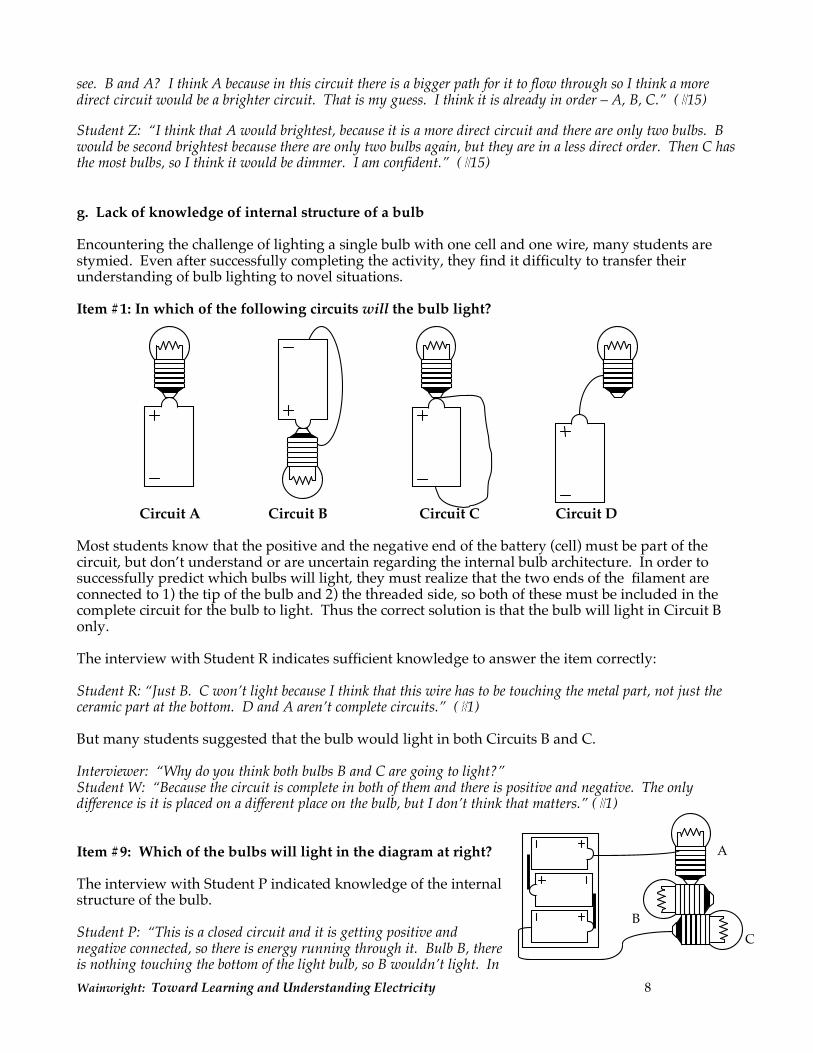
see. B and A? I think A because in this circuit there is a bigger path for it to flow through so I think a more direct circuit would be a brighter circuit. That is my guess. I think it is already in order – A, B, C.” (#15) Student Z: “I think that A would brightest, because it is a more direct circuit and there are only two bulbs. B would be second brightest because there are only two bulbs again, but they are in a less direct order. Then C has the most bulbs, so I think it would be dimmer. I am confident.” (#15) g. Lack of knowledge of internal structure of a bulb Encountering the challenge of lighting a single bulb with one cell and one wire, many students are stymied. Even after successfully completing the activity, they find it difficulty to transfer their understanding of bulb lighting to novel situations. Item #1: In which of the following circuits will the bulb light? Circuit A Circuit B Circuit C Circuit D Most students know that the positive and the negative end of the battery (cell) must be part of the circuit, but don’t understand or are uncertain regarding the internal bulb architecture. In order to successfully predict which bulbs will light, they must realize that the two ends of the filament are connected to 1) the tip of the bulb and 2) the threaded side, so both of these must be included in the complete circuit for the bulb to light. Thus the correct solution is that the bulb will light in Circuit B only. The interview with Student R indicates sufficient knowledge to answer the item correctly: Student R: “Just B. C won’t light because I think that this wire has to be touching the metal part, not just the ceramic part at the bottom. D and A aren’t complete circuits.” (#1) But many students suggested that the bulb would light in both Circuits B and C. Interviewer: “Why do you think both bulbs B and C are going to light?” Student W: “Because the circuit is complete in both of them and there is positive and negative. The only difference is it is placed on a different place on the bulb, but I don’t think that matters.” (#1) Item #9: Which of the bulbs will light in the diagram at right? The interview with Student P indicated knowledge of the internal structure of the bulb. Student P: “This is a closed circuit and it is getting positive and negative connected, so there is energy running through it. Bulb B, there is nothing touching the bottom of the light bulb, so B wouldn’t light. In
A
B C
Wainwright: Toward Learning and Understanding Electricity 9
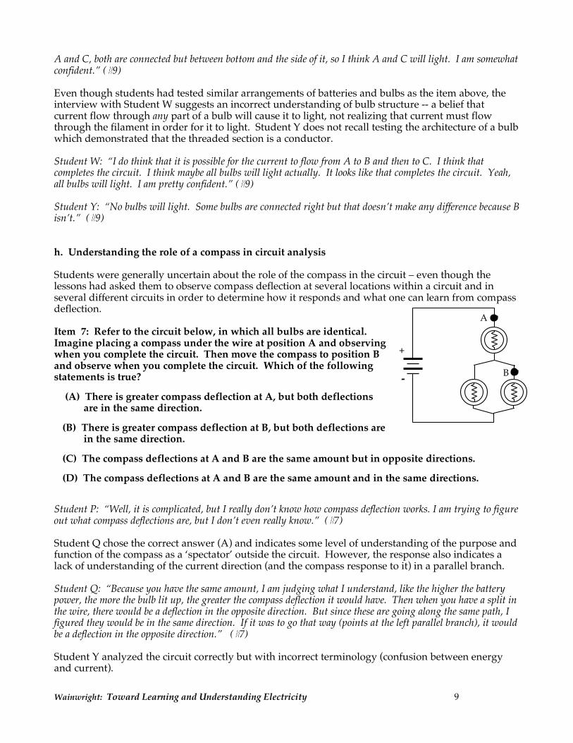
A and C, both are connected but between bottom and the side of it, so I think A and C will light. I am somewhat confident.” (#9) Even though students had tested similar arrangements of batteries and bulbs as the item above, the interview with Student W suggests an incorrect understanding of bulb structure -- a belief that current flow through any part of a bulb will cause it to light, not realizing that current must flow through the filament in order for it to light. Student Y does not recall testing the architecture of a bulb which demonstrated that the threaded section is a conductor. Student W: “I do think that it is possible for the current to flow from A to B and then to C. I think that completes the circuit. I think maybe all bulbs will light actually. It looks like that completes the circuit. Yeah, all bulbs will light. I am pretty confident.” (#9) Student Y: “No bulbs will light. Some bulbs are connected right but that doesn’t make any difference because B isn’t.” (#9) h. Understanding the role of a compass in circuit analysis Students were generally uncertain about the role of the compass in the circuit – even though the lessons had asked them to observe compass deflection at several locations within a circuit and in several different circuits in order to determine how it responds and what one can learn from compass deflection. Item 7: Refer to the circuit below, in which all bulbs are identical. Imagine placing a compass under the wire at position A and observing when you complete the circuit. Then move the compass to position B and observe when you complete the circuit. Which of the following statements is true?
(A) There is greater compass deflection at A, but both deflections
are in the same direction. (B) There is greater compass deflection at B, but both deflections are
in the same direction. (C) The compass deflections at A and B are the same amount but in opposite directions. (D) The compass deflections at A and B are the same amount and in the same directions.
Student P: “Well, it is complicated, but I really don’t know how compass deflection works. I am trying to figure out what compass deflections are, but I don’t even really know.” (#7) Student Q chose the correct answer (A) and indicates some level of understanding of the purpose and function of the compass as a ‘spectator’ outside the circuit. However, the response also indicates a lack of understanding of the current direction (and the compass response to it) in a parallel branch. Student Q: “Because you have the same amount, I am judging what I understand, like the higher the battery power, the more the bulb lit up, the greater the compass deflection it would have. Then when you have a split in the wire, there would be a deflection in the opposite direction. But since these are going along the same path, I figured they would be in the same direction. If it was to go that way (points at the left parallel branch), it would be a deflection in the opposite direction.” (#7) Student Y analyzed the circuit correctly but with incorrect terminology (confusion between energy and current).
B
A
+
-

Wainwright: Toward Learning and Understanding Electricity 10
Student Y: “I am thinking, again, the energy is going through here. It is not all the energy, so it won’t go up. So D.” (#7) i. Incorrect vocabulary Most students had not acquired a firm and confident ability to use appropriate electrical terminology. They routinely used terms without precision or accuracy and somewhat interchangeably, including energy, current, voltage, resistance, ‘juice’, power, electric pressure difference, electricity, ‘wattage’, etc. Student P: “ . . . you could assume red being the highest energy or current or voltage or something.” (#7) “When you pay for a household bill, you pay for the energy you use, because voltage is a measure of how much energy is used in a given time.” (#10) Student W: “When paying a household electric bill, what does one actually pay for? I think you pay for voltage. In terms of energy, what you are actually paying for that is making things work is the volts coming in. Again, you don’t say I want so-and-so volts, but the energy itself. They don’t charge you for volts, you know what I mean? They do charge for how much volts you use.” (#10) j. Capacitor charging and discharging Many students don’t understand what is occurring while a capacitor is charging even after numerous experiences in observing bulbs during capacitor charging and discharging. Some can recall the readings and class discussion describing the structure of a capacitor – that it contains a very high resistance barrier so that charge cannot flow through it, and consequently charge is compressed on one plate while depleted on the other during charging. Nevertheless, if needed they invoke the notion that some charge at least flows right through the capacitor. Student P: “Charging a capacitor, I think that as electricity passes through it, some of it is stored inside of the capacitor and then the rest of it is passed through to the rest of the circuit.” (#5) Student Q: “The battery is going to charge up this side, it will light this bulb A and whatever is left will stay in the capacitor until the capacitor is connected and empties into bulb B on the other side and then it cycles again.” (#5) k. Circuit analysis via color-coding Many students do not understand the value of using color-coding (Steinberg, 2005) to analyze a circuit, or they use it perfunctorily without deep understanding. Student P demonstrates on Item #7 a lack of skill in applying the color-coding procedure. On Item #15, however, the same student had been able to arrive at the correct analysis by applying the color-coding analysis correctly; thus only a superficial ability to use the color-coding strategy had been acquired. Student P: “Well, the way we were taught is something like you could assume red being the highest energy or current or voltage or something, and then from here is blue, and in between is – blue would go both ways – For the middle wire, yellow, I figure. But because B is in yellow and A is in red, I don’t know if that makes any difference. I’d say, I’d guess that because A is in the red, that it would have a greater compass deflection because compass deflection has something to do with how much energy is being passed.” (#7) Student R used the color-coding strategy to reach the correct answer, but with only a partial understanding of what the model represents.
Wainwright: Toward Learning and Understanding Electricity 11
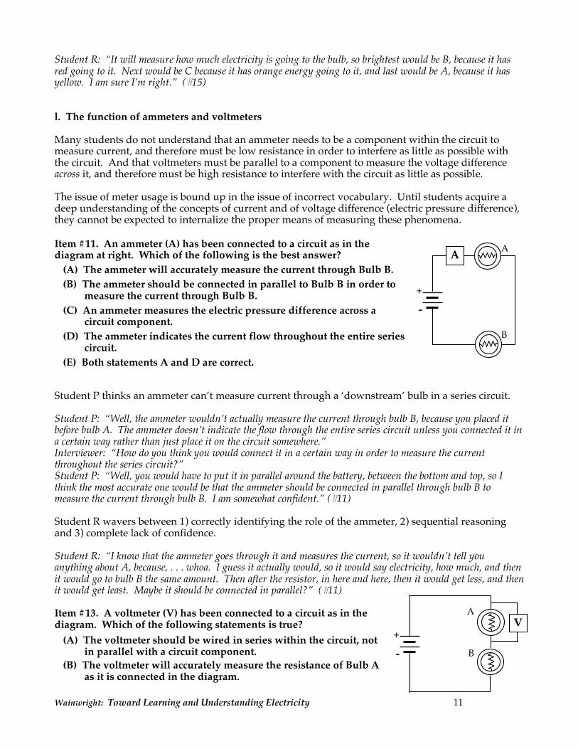
Student R: “It will measure how much electricity is going to the bulb, so brightest would be B, because it has red going to it. Next would be C because it has orange energy going to it, and last would be A, because it has yellow. I am sure I’m right.” (#15) l. The function of ammeters and voltmeters Many students do not understand that an ammeter needs to be a component within the circuit to measure current, and therefore must be low resistance in order to interfere as little as possible with the circuit. And that voltmeters must be parallel to a component to measure the voltage difference across it, and therefore must be high resistance to interfere with the circuit as little as possible. The issue of meter usage is bound up in the issue of incorrect vocabulary. Until students acquire a deep understanding of the concepts of current and of voltage difference (electric pressure difference), they cannot be expected to internalize the proper means of measuring these phenomena. Item #11. An ammeter (A) has been connected to a circuit as in the diagram at right. Which of the following is the best answer?
(A) The ammeter will accurately measure the current through Bulb B.
(B) The ammeter should be connected in parallel to Bulb B in order to measure the current through Bulb B.
(C) An ammeter measures the electric pressure difference across a circuit component.
(D) The ammeter indicates the current flow throughout the entire series circuit.
(E) Both statements A and D are correct.
Student P thinks an ammeter can’t measure current through a ‘downstream’ bulb in a series circuit. Student P: “Well, the ammeter wouldn’t actually measure the current through bulb B, because you placed it before bulb A. The ammeter doesn’t indicate the flow through the entire series circuit unless you connected it in a certain way rather than just place it on the circuit somewhere.” Interviewer: “How do you think you would connect it in a certain way in order to measure the current throughout the series circuit?” Student P: “Well, you would have to put it in parallel around the battery, between the bottom and top, so I think the most accurate one would be that the ammeter should be connected in parallel through bulb B to measure the current through bulb B. I am somewhat confident.” (#11) Student R wavers between 1) correctly identifying the role of the ammeter, 2) sequential reasoning and 3) complete lack of confidence. Student R: “I know that the ammeter goes through it and measures the current, so it wouldn’t tell you anything about A, because, . . . whoa. I guess it actually would, so it would say electricity, how much, and then it would go to bulb B the same amount. Then after the resistor, in here and here, then it would get less, and then it would get least. Maybe it should be connected in parallel?” (#11) Item #13. A voltmeter (V) has been connected to a circuit as in the diagram. Which of the following statements is true?
(A) The voltmeter should be wired in series within the circuit, not in parallel with a circuit component.
(B) The voltmeter will accurately measure the resistance of Bulb A as it is connected in the diagram.
A
B
A
- +
A
B - +
V
Wainwright: Toward Learning and Understanding Electricity 12
(C) The voltmeter will accurately measure the electric pressure difference across Bulb A.
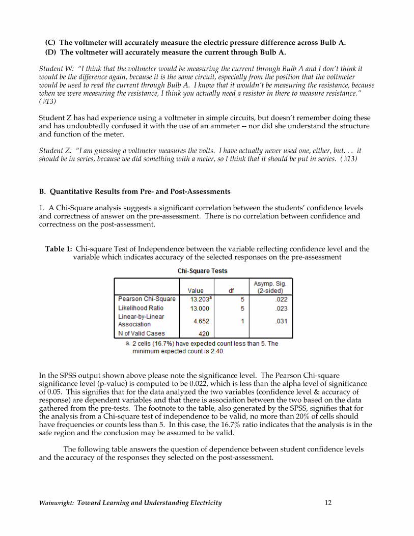
(D) The voltmeter will accurately measure the current through Bulb A. Student W: “I think that the voltmeter would be measuring the current through Bulb A and I don’t think it would be the difference again, because it is the same circuit, especially from the position that the voltmeter would be used to read the current through Bulb A. I know that it wouldn’t be measuring the resistance, because when we were measuring the resistance, I think you actually need a resistor in there to measure resistance.” (#13) Student Z has had experience using a voltmeter in simple circuits, but doesn’t remember doing these and has undoubtedly confused it with the use of an ammeter -- nor did she understand the structure and function of the meter. Student Z: “I am guessing a voltmeter measures the volts. I have actually never used one, either, but. . . it should be in series, because we did something with a meter, so I think that it should be put in series. (#13) B. Quantitative Results from Pre- and Post-Assessments 1. A Chi-Square analysis suggests a significant correlation between the students’ confidence levels and correctness of answer on the pre-assessment. There is no correlation between confidence and correctness on the post-assessment.
Table 1: Chi-square Test of Independence between the variable reflecting confidence level and the variable which indicates accuracy of the selected responses on the pre-assessment
In the SPSS output shown above please note the significance level. The Pearson Chi-square significance level (p-value) is computed to be 0.022, which is less than the alpha level of significance of 0.05. This signifies that for the data analyzed the two variables (confidence level & accuracy of response) are dependent variables and that there is association between the two based on the data gathered from the pre-tests. The footnote to the table, also generated by the SPSS, signifies that for the analysis from a Chi-square test of independence to be valid, no more than 20% of cells should have frequencies or counts less than 5. In this case, the 16.7% ratio indicates that the analysis is in the safe region and the conclusion may be assumed to be valid. The following table answers the question of dependence between student confidence levels and the accuracy of the responses they selected on the post-assessment.
Wainwright: Toward Learning and Understanding Electricity 13
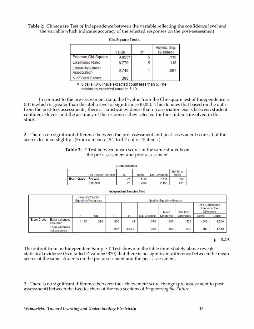
Table 2: Chi-square Test of Independence between the variable reflecting the confidence level and the variable which indicates accuracy of the selected responses on the post-assessment
In contrast to the pre-assessment data, the P-value from the Chi-square test of Independence is 0.116 which is greater than the alpha level of significance (0.05). This denotes that based on the data from the post-test assessments, there is statistical evidence that no association exists between student confidence levels and the accuracy of the responses they selected for the students involved in this study. 2. There is no significant difference between the pre-assessment and post-assessment scores, but the scores declined slightly. (From a mean of 5.2 to 4.7 out of 15 items.)
Table 3: T-Test between mean scores of the same students on the pre-assessment and post-assessment
p = 0.370
The output from an Independent Sample T-Test shown in the table immediately above reveals statistical evidence (two tailed P-value=0.370) that there is no significant difference between the mean scores of the same students on the pre-assessment and the post-assessment. 3. There is no significant difference between the achievement score change (pre-assessment to post-assessment) between the two teachers of the two sections of Engineering the Future.

Wainwright: Toward Learning and Understanding Electricity 14
Table 4: Comparison of Pre-Assessment and Post-Assessment score change by Teacher
The Independent Sample T-Test was run on the scores of all the students of both teachers who took both the Pre-assessment and Post-assessments; if a student took one but did not take the other, he/she was excluded from the analysis. The above result shows no significant difference (two tailed P-value = 0.300) between the mean score changes of students in Teacher X and Y’s classrooms. VI. Discussion Providing students with an opportunity to indicate their level of confidence in selecting an answer is of definite interest to a teacher who chooses to analyze the data. In this case, however, there was only a significant correlation between confidence and correctness of the answer on the pre-assessment. This correlation did not exist on the post-assessment. Based on observations during interviews, it appeared that many students claimed confidence even when answers were wrong, and lack of confidence when answer were right; this suggests that many were simply guessing in spite of nearly five weeks of instruction. Why did these students score so low on the achievement test, make so little gain from the pre- to post-assessment (or even decline), and retain (or develop) so many misconceptions? The following discussion is speculative on the par of the author. Electricity concepts by their very nature must be constructed at a high level of abstraction. One can never observe the charges moving within a circuit or being compressed in a capacitor. One must make inferences indirectly from observable evidence. This requires time, questioning, discourse, and repeated confrontation of the same ideas in multiple circuits. This entire unit was taught in just over four weeks, by two teachers with very little background in electricity and limited professional development focused on the curriculum. In fact, the teachers themselves often used terminology with lack of precision (e.g., ‘power’ for ‘energy’ and ‘juice’ for ‘current’). The curriculum was new (just off the press) and not yet refined. The curriculum developers had limited classroom teaching experience, and failed to recognize the importance or even necessity of providing students with multiple activities to reinforce the same concept. “It requires three to four experiences involving interaction with relevant information for a new knowledge construct to be created in working memory and then transferred to long-term memory.” (Nuthall, 1999) In addition, the circuit elements (wires, capacitors, ammeters, bulbs, etc.) were components within a Snap Circuits kit. While the students enjoyed the elegant simplicity of constructing circuits by simply snapping them together, these components introduced new challenges. For example, proper polarity had to be maintained for many components (capacitor, ammeter, voltmeter) long before they had
Teacher X Teacher Y
Wainwright: Toward Learning and Understanding Electricity 15
developed an understanding of what the + and – poles represented. For many students, the necessity of maintaining proper polarity added sufficient complexity to guarantee constant confusion. Studies suggest that even students accepting the battery as a causal agent have no idea of the conservation of electricity (‘recycling’ of charge) nor do they see a need for a closed circuit. A significant number of students “think that one wire between battery and bulb suffices and that the second wire to be found in working circuits in everyday life simply serves to bring more current to the bulb.” (Duit, p. 1-2.) How do these rampant misconceptions arise? Many are based on common sense and everyday prior experience. For example, the term “rechargeable” battery strongly but incorrectly suggests that the battery supplies charge to a circuit. Since the charge already exists throughout the conductors, it is the battery’s role to supply the energy necessary to push/pull it around the circuit but not to supply charge. Consequently, “re-energizeable” would be a more accurate descriptive term. Textbook explanations and diagrams are often the source or reinforcements of misconceptions in electricity. They generally tend to emphasize a numerical rather than conceptual approach, and often implant misconceptions unintentionally. (For example, Ohm’s Law is often mis-applied. Using V = IR, students conclude incorrectly that there can be no voltage difference across an open switch since no current flows.) The use of a water analogy (ubiquitous in textbooks) leads to reinforced misconceptions. They see the faucet as a source of water. (This is analogous, they believe, to the battery as the source of charge. Diagrams often show current originating at the battery and returning to the other pole, rather than through the battery.) In addition, the flow of water responds to gravity which certainly does not apply to charge flow. And the notion of the compressibility of charge (as in a capacitor) cannot be modeled with an incompressible fluid such as water. The air model is far more intuitive, but unfortunately students have limited experience with compressed air and pneumatics. While clinical interviews can be used to probe for the level of student understanding, they do not in and of themselves provide a roadmap for teaching strategies to overcome existing misconceptions. However, clues for promising methods can be found. For example, Student W suggested the following: “I think a bicycle chain could be used as an allusion to, like you said, the flow of electricity, because say you are pedaling on a bicycle. The current just continues to go on and on through, unless something stops that current, unless you stop it yourself, fall or whatever stops it, it keeps the force going so you keep on going as long as you are pushing. The flow of electricity, say you are connected to a battery and put two ends of a wire on that battery, unless you move one of the places, one of the wires off the end of the battery or do something else to stop the flow, it is just going to continue in the same direction. That is what I get from that.” Closely related to the student’s model of a bicycle chain as current is the Hula Hoop Model described in Appendix B. This model was also incorporated into the Engineering the Future curriculum. One CASTLE strategy for countering incorrect use of language is the following: require students to ‘earn’ vocabulary. They can only use a technical term (resistance, voltage, energy, power, etc.) when they can operationally define it or demonstrate its characteristics within a circuit. This technique has proven effective in developing communication skills in which students are thoughtful and precise in describing their observations and in problem-solving. Chinn and Brewer (1993) emphasize the necessity of explicit comparison of students’ preconceptions with new observations as a means of promoting the construction of deeper understanding in order to abandon or modify previous naïve conceptions. Conceptual change is intended to move students from their pre-instructional beliefs to accepted physics perspectives, but the process requires both rational and emotional processing. A supporting environment must be provided which encourages the students to predict, observe, and develop divergent explanations, which can be shared with other students through interactive discourse. “Among these supporting conditions are a classroom climate that allows students to voice their ideas and to exchange their views with other students, and where students’ ideas generally are taken as serious attempts to make sense of a certain phenomenon by the
Wainwright: Toward Learning and Understanding Electricity 16
teachers.” (Duit, p. 6) The CASTLE curriculum was designed to periodically employ classroom discourse through teacher-led ‘model-building discussions’. (Steinberg et al, 2005) See some of the results of research on the use of the CASTLE curriculum in Appendix C. Although the CASTLE approach formed the initial foundation for the development of the Engineering the Future section on electricity, it appears to have lost some of its effectiveness in the adaptation. The developers are using the results of the assessments and interviews to guide them in further refining this section of the curriculum and in the professional development support for the classroom teachers. Curriculum developers at the Museum of Science have been very appreciative of the work on this project, even though it indicates that the first draft of their curriculum was inadequate in helping students overcome their misconceptions. They are currently working with the author to revise the curriculum so that students have more opportunities to articulate their personal theories of electrical phenomena, to make predictions about experimental circuits, and to discuss the results with guidance from the teacher. They are also devising embedded assessments so that the teacher can check their students' understanding at key points during the unit as a formative tool to increase the effectiveness of the curriculum. VII. Conclusions David Ausubel suggested “the most important single factor influencing learning is what the learner already knows. Ascertain this and teach him accordingly.” (Ausubel, 1968) While pre- and post-assessments are of value in this regard, a paper-and-pencil pre-test is no substitute for a clinical interview. Piaget championed the use of clinical interviews as a means of learning not only whether students could parrot a correct answer, but as a tool for gaining insight into their cognitive processes as well as for learning their depth of understanding. (Piaget, 1930) Although time-consuming and logistically-challenging, interviews can serve as excellent pre-assessment tools, formative or embedded techniques during instruction, or as post-assessment methodology. Taking account of students’ prior knowledge is critical to successful planning of effective lessons. Teachers must not only be aware, in general, of the common misconceptions in the content areas they teach, but must also have developed the skills necessary to probe and detect the specific naïve conceptions among individual students in their own classrooms. Only then are they able to structure their teaching for effective conceptual change.
Wainwright: Toward Learning and Understanding Electricity 17
VIII. References Ausubel, D. P. (1968). Educational Psychology: A Cognitive View. Holt, Winston, Rinehart, p. vi. Bell, B., Osbourne, R. & Tasker, R. (1985) Finding out what children think. In Osbourne, R & Freyberg, P. (1985). Learning in science: the implications of children’s science (pp. 5 – 27). London: Heinemann. Brown, D. E. (1992), Teaching electricity with capacitors and causal models: Preliminary results from diagnostic and tutoring study data examining the CASTLE Project. Paper presented at annual meeting of NARST in Boston, MA. Chi, M.T.H., Slotta, J.D. & DeLeeuw, N. (1994). From things to processes: a theory of conceptual change for learning science concepts. Learning and Instruction, 4, 27-43. Chinn, C.A. & Brewer, W.F. (1993) The role of anomalous data in knowledge acquisition: A theoretical framework and implications for science instruction. Review of Educational Research, 63(`), 1 – 49. Clement, J. (1987) Overcoming students’ misconceptions in physics: The role of anchoring intuitions and analogical validity. In J. D. Novak (Ed.) Proceedings of the Second International Seminar, Misconceptions and Educational Strategies in Science and Mathematics, vol. III (434-437). Cornell University. Cohen, R., Eylon, B. and Ganiel, U. (1983) difference and current in simple electric circuits: A student of students’ concepts. American J. of Physics 57:5, 407-412. Driver, R., Guesne, E. & Tiberghien, A. (1985). Children’s ideas in Science. Buckingham, UK: Open University Press. Duit, R., Jung W., & Rhoneck, C. (1985). (Eds.) Aspects of Understanding Electricity: Proceedings of an International Workshop (Schmit and Klaunig, Kiel, Germany) MCAS Standards: 2001 Massachusetts Science and Technology/Engineering Curriculum Framework. Available on-line at the Massachusetts Department of Education website: (www.doe.mass.edu/frameworks/current.html). McDermott, L. C. and Schaffer, P. S. (1992). Research as a Guide for Curriculum Development: An Example from Introductory Electricity. Part I: Investigation of Student Understanding, American Journal of Physics 60, 994-1003. Nuthall, G.A. (1999). The way students learn. Elementary School Journal, 99, 303-341. Osborne, R. (1983) Modifying children’s ideas about electric current. Research in Science and Technological Education 1 (1), 73-82. Piaget, J. The Child’s Conception of Physical Causality. 1930. New York: Harcourt Brace. Psillos, D. (1997). Teaching Introductory Electricity in Connecting Research in Physics Education with Teacher Education. International Commission on Physics Education. Raduta, C. (1998) General Students’ Misconceptions Related to Electricity and Magnetism. Doctoral dissertation, The Ohio State University,
Wainwright: Toward Learning and Understanding Electricity 18
Roth, W., & Roychoudhury, A. (1992). The social construction of scientific concepts or the concept map as conscription device and tool for social thinking in high school science. Science Education, 76 (5), 531-557. Shipstone, D.M., Rhoneck, C. von, Jung, W., Karrqvist, C., Dupin, Joshua S., & Licht, P. (1988). A study of Secondary students’ understanding of electricity in five European countries. International Journal of Science Education 10, 303 – 316. Steinberg, M. , Bryant, Cronin, Cunha, Drenchko, Ewald, Feren, FitzGibbons, McNamara, Maholtz, Matsler, Morse, Nelson, Otto, Senior, Turner, Wainwright. (2005). Electricity Visualized: The CASTLE Approach. PASCO scientific: Roseville, CA. (CASTLE curriculum may be downloaded at no cost from: http://store.pasco.com/pascostore/showdetl.cfm?&DS_ID=2&Product_ID=51804&DID=9&Detail=1 Steinberg, M., Wainwright, C. (1993). Using models to teach electricity – The CASTLE project. The Physics Teacher, 31: 353.
Wainwright: Toward Learning and Understanding Electricity 19
APPENDIX A
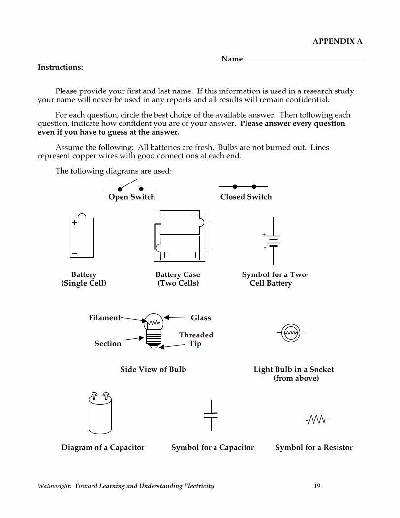
Name Instructions:
Please provide your first and last name. If this information is used in a research study
your name will never be used in any reports and all results will remain confidential. For each question, circle the best choice of the available answer. Then following each
question, indicate how confident you are of your answer. Please answer every question even if you have to guess at the answer.
Assume the following: All batteries are fresh. Bulbs are not burned out. Lines
represent copper wires with good connections at each end. The following diagrams are used:
Open Switch Closed Switch Battery Battery Case Symbol for a Two-
(Single Cell) (Two Cells) Cell Battery
Filament Glass Threaded Section Tip
Side View of Bulb Light Bulb in a Socket
(from above)
Diagram of a Capacitor Symbol for a Capacitor Symbol for a Resistor
- +
Wainwright: Toward Learning and Understanding Electricity 20
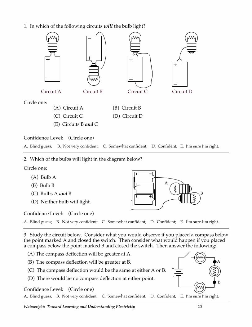
1. In which of the following circuits will the bulb light?
Circuit A Circuit B Circuit C Circuit D Circle one:
(A) Circuit A (B) Circuit B (C) Circuit C (D) Circuit D (E) Circuits B and C
Confidence Level: (Circle one) A. Blind guess; B. Not very confident; C. Somewhat confident; D. Confident; E. I’m sure I’m right. 2. Which of the bulbs will light in the diagram below? Circle one:
(A) Bulb A (B) Bulb B (C) Bulbs A and B (D) Neither bulb will light.
Confidence Level: (Circle one) A. Blind guess; B. Not very confident; C. Somewhat confident; D. Confident; E. I’m sure I’m right. 3. Study the circuit below. Consider what you would observe if you placed a compass below the point marked A and closed the switch. Then consider what would happen if you placed a compass below the point marked B and closed the switch. Then answer the following:
(A) The compass deflection will be greater at A. (B) The compass deflection will be greater at B. (C) The compass deflection would be the same at either A or B. (D) There would be no compass deflection at either point.
Confidence Level: (Circle one)
A. Blind guess; B. Not very confident; C. Somewhat confident; D. Confident; E. I’m sure I’m right.
A
B - +
A
B
Wainwright: Toward Learning and Understanding Electricity 21
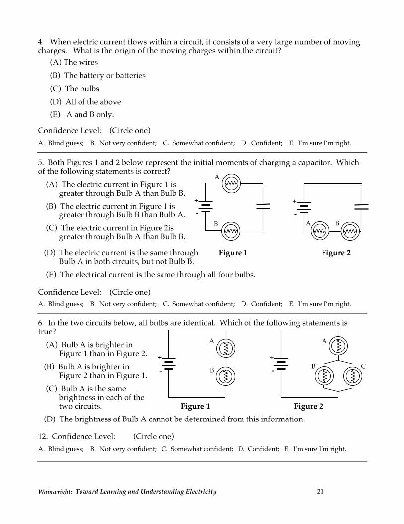
4. When electric current flows within a circuit, it consists of a very large number of moving charges. What is the origin of the moving charges within the circuit?
(A) The wires (B) The battery or batteries (C) The bulbs (D) All of the above (E) A and B only.
Confidence Level: (Circle one) A. Blind guess; B. Not very confident; C. Somewhat confident; D. Confident; E. I’m sure I’m right.
5. Both Figures 1 and 2 below represent the initial moments of charging a capacitor. Which of the following statements is correct?
(A) The electric current in Figure 1 is greater through Bulb A than Bulb B.
(B) The electric current in Figure 1 is greater through Bulb B than Bulb A.
(C) The electric current in Figure 2is greater through Bulb A than Bulb B.
(D) The electric current is the same through Figure 1 Figure 2 Bulb A in both circuits, but not Bulb B.
(E) The electrical current is the same through all four bulbs.
Confidence Level: (Circle one)
A. Blind guess; B. Not very confident; C. Somewhat confident; D. Confident; E. I’m sure I’m right.
6. In the two circuits below, all bulbs are identical. Which of the following statements is true?
(A) Bulb A is brighter in Figure 1 than in Figure 2.
(B) Bulb A is brighter in Figure 2 than in Figure 1.
(C) Bulb A is the same brightness in each of the two circuits. Figure 1 Figure 2
(D) The brightness of Bulb A cannot be determined from this information. 12. Confidence Level: (Circle one) A. Blind guess; B. Not very confident; C. Somewhat confident; D. Confident; E. I’m sure I’m right.
A
B - +
A B - +
C B
A A
B - +
- +

Wainwright: Toward Learning and Understanding Electricity 22
7. Refer to the circuit below, in which all bulbs are identical. Imagine placing a compass under the wire at position A and observing when you complete the circuit. Then move the compass to position B and observe when you complete the circuit. Which of the following statements is true?
(A) There is greater compass deflection at A, but both deflections are in the same direction.
(B) There is greater compass deflection at B, but both deflections are in the same direction.
(C) The compass deflections at A and B are the same amount but in opposite directions.
(D) The compass deflections at A and B are the same amount and in the same directions.
Confidence Level: (Circle one)
A. Blind guess; B. Not very confident; C. Somewhat confident; D. Confident; E. I’m sure I’m right.
8. In the circuit shown, both bulbs A and B are identical and both are lit equally bright. If a wire is attached around bulb B to each side of the bulb B socket, predict what you would observe.
(A) Bulb A gets much brighter
(B) Bulb A gets much dimmer or goes out
(C) Bulb A stays about the same brightness. Confidence Level: (Circle one)
A. Blind guess; B. Not very confident; C. Somewhat confident; D. Confident; E. I’m sure I’m right.
9. In the circuit at the right, predict which bulb(s) will light.
(A) All bulbs will light.
(B) No bulbs will light.
(C) Bulbs A and B will light.
(D) Bulbs A and C will light.
(E) Bulbs B and C will light. Confidence Level: (Circle one)
A. Blind guess; B. Not very confident; C. Somewhat confident; D. Confident; E. I’m sure I’m right.
10. When paying a household electric bill, what does one actually pay for?
(A) Energy
(B) Voltage
(C) Current consisting of charges moving in one direction
(D) Current consisting of charges moving in alternating directions
Confidence Level: (Circle one)
A. Blind guess; B. Not very confident; C. Somewhat confident; D. Confident; E. I’m sure I’m right.
A B
- +
B
A
+
-
A
B C
Wainwright: Toward Learning and Understanding Electricity 23
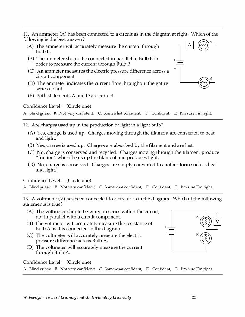
11. An ammeter (A) has been connected to a circuit as in the diagram at right. Which of the following is the best answer?
(A) The ammeter will accurately measure the current through Bulb B.
(B) The ammeter should be connected in parallel to Bulb B in order to measure the current through Bulb B.
(C) An ammeter measures the electric pressure difference across a circuit component.
(D) The ammeter indicates the current flow throughout the entire series circuit.
(E) Both statements A and D are correct. Confidence Level: (Circle one)
A. Blind guess; B. Not very confident; C. Somewhat confident; D. Confident; E. I’m sure I’m right. 12. Are charges used up in the production of light in a light bulb?
(A) Yes, charge is used up. Charges moving through the filament are converted to heat and light.
(B) Yes, charge is used up. Charges are absorbed by the filament and are lost.
(C) No, charge is conserved and recycled. Charges moving through the filament produce “friction” which heats up the filament and produces light.
(D) No, charge is conserved. Charges are simply converted to another form such as heat and light.
Confidence Level: (Circle one)
A. Blind guess; B. Not very confident; C. Somewhat confident; D. Confident; E. I’m sure I’m right.
13. A voltmeter (V) has been connected to a circuit as in the diagram. Which of the following statements is true?
(A) The voltmeter should be wired in series within the circuit, not in parallel with a circuit component.
(B) The voltmeter will accurately measure the resistance of Bulb A as it is connected in the diagram.
(C) The voltmeter will accurately measure the electric pressure difference across Bulb A.
(D) The voltmeter will accurately measure the current through Bulb A.
Confidence Level: (Circle one)
A. Blind guess; B. Not very confident; C. Somewhat confident; D. Confident; E. I’m sure I’m right.
A
B
A
- +
A
B - +
V
Wainwright: Toward Learning and Understanding Electricity 24
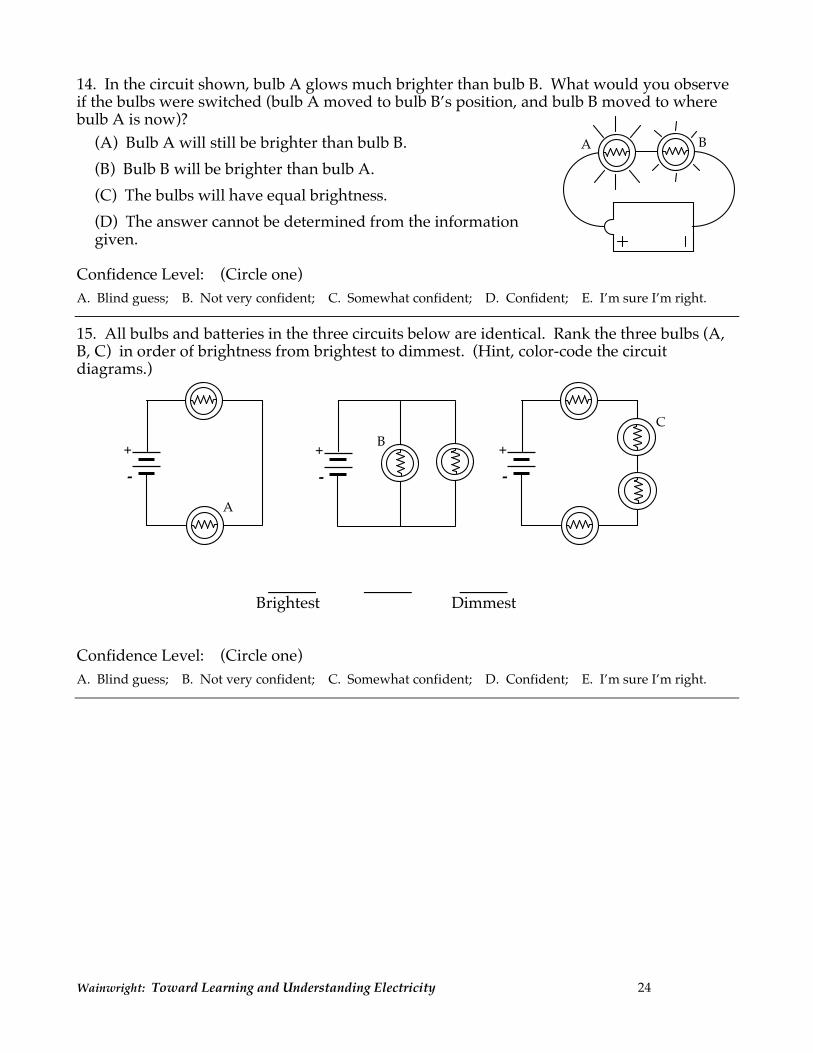
14. In the circuit shown, bulb A glows much brighter than bulb B. What would you observe if the bulbs were switched (bulb A moved to bulb B’s position, and bulb B moved to where bulb A is now)?
(A) Bulb A will still be brighter than bulb B.
(B) Bulb B will be brighter than bulb A.
(C) The bulbs will have equal brightness.
(D) The answer cannot be determined from the information given.
Confidence Level: (Circle one)
A. Blind guess; B. Not very confident; C. Somewhat confident; D. Confident; E. I’m sure I’m right.
15. All bulbs and batteries in the three circuits below are identical. Rank the three bulbs (A, B, C) in order of brightness from brightest to dimmest. (Hint, color-code the circuit diagrams.)
Brightest Dimmest Confidence Level: (Circle one)
A. Blind guess; B. Not very confident; C. Somewhat confident; D. Confident; E. I’m sure I’m right.
A B
C
A
B
- +
- +
- +

Wainwright: Toward Learning and Understanding Electricity 25
Answers: 1. B 2. B 3. C 4. D 5. E 6. B 7. A 8. C 9. D 10. A 11. E 12. C 13. C 14. A 15. B > A > C Possible answers: A. ABC B. BCA C. CAB D. BAC (Correct) E. ACB F. CBA
Wainwright: Toward Learning and Understanding Electricity 26
APPENDIX B
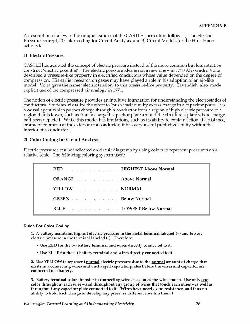
A description of a few of the unique features of the CASTLE curriculum follow: 1) The Electric Pressure concept, 2) Color-coding for Circuit Analysis, and 3) Circuit Models (or the Hula Hoop activity). 1) Electric Pressure: CASTLE has adopted the concept of electric pressure instead of the more common but less intuitive construct ‘electric potential’. The electric pressure idea is not a new one – in 1778 Alessandro Volta described a pressure-like property in electrified conductors whose value depended on the degree of compression. His earlier research on gases may have played a role in his adoption of an air-like model. Volta gave the name ‘electric tension’ to this pressure-like property. Cavendish, also, made explicit use of the compressed air analogy in 1771. The notion of electric pressure provides an intuitive foundation for understanding the electrostatics of conductors. Students visualize the effort to ‘push itself out’ by excess charge in a capacitor plate. It is a causal agent which pushes charge through a conductor from a region of high electric pressure to a region that is lower, such as from a charged capacitor plate around the circuit to a plate where charge had been depleted. While this model has limitations, such as its ability to explain action at a distance, or any phenomena at the exterior of a conductor, it has very useful predictive ability within the interior of a conductor. 2) Color-Coding for Circuit Analysis Electric pressures can be indicated on circuit diagrams by using colors to represent pressures on a relative scale. The following coloring system used:
RED . . . . . . . . . . . . HIGHEST Above Normal ORANGE . . . . . . . . . . Above Normal YELLOW . . . . . . . . . . NORMAL GREEN . . . . . . . . . . . Below Normal BLUE . . . . . . . . . . . . LOWEST Below Normal
Rules For Color Coding
1. A battery maintains highest electric pressure in the metal terminal labeled (+) and lowest electric pressure in the terminal labeled (–). Therefore:
• Use RED for the (+) battery terminal and wires directly connected to it.
• Use BLUE for the (–) battery terminal and wires directly connected to it.
2. Use YELLOW to represent normal electric pressure due to the normal amount of charge that exists in a connecting wires and uncharged capacitor plates before the wires and capacitor are connected to a battery. 3. Battery terminal colors transfer to connecting wires as soon as the wires touch. Use only one color throughout each wire – and throughout any group of wires that touch each other – as well as throughout any capacitor plate connected to it. (Wires have nearly zero resistance, and thus no ability to hold back charge or develop any pressure difference within them.)
Wainwright: Toward Learning and Understanding Electricity 27
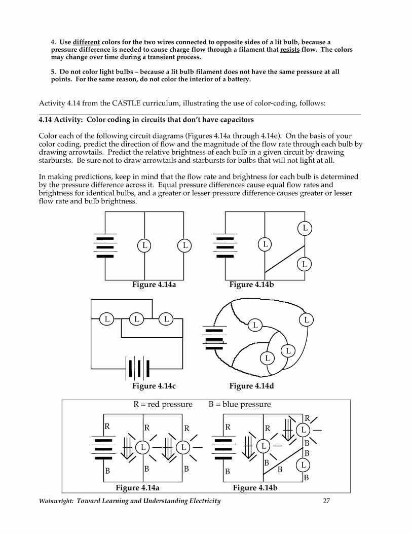
4. Use different colors for the two wires connected to opposite sides of a lit bulb, because a pressure difference is needed to cause charge flow through a filament that resists flow. The colors may change over time during a transient process. 5. Do not color light bulbs – because a lit bulb filament does not have the same pressure at all points. For the same reason, do not color the interior of a battery.
Activity 4.14 from the CASTLE curriculum, illustrating the use of color-coding, follows: 4.14 Activity: Color coding in circuits that don’t have capacitors Color each of the following circuit diagrams (Figures 4.14a through 4.14e). On the basis of your color coding, predict the direction of flow and the magnitude of the flow rate through each bulb by drawing arrowtails. Predict the relative brightness of each bulb in a given circuit by drawing starbursts. Be sure not to draw arrowtails and starbursts for bulbs that will not light at all. In making predictions, keep in mind that the flow rate and brightness for each bulb is determined by the pressure difference across it. Equal pressure differences cause equal flow rates and brightness for identical bulbs, and a greater or lesser pressure difference causes greater or lesser flow rate and bulb brightness.
LL L
L
L
Figure 4.14a Figure 4.14b
L
LLL LL
L
Figure 4.14c Figure 4.14d
R R R
B B B
LL
BB
B
B
R RR
B
BL
R = red pressure B = blue pressure
L
L
Figure 4.14a Figure 4.14b
Wainwright: Toward Learning and Understanding Electricity 28
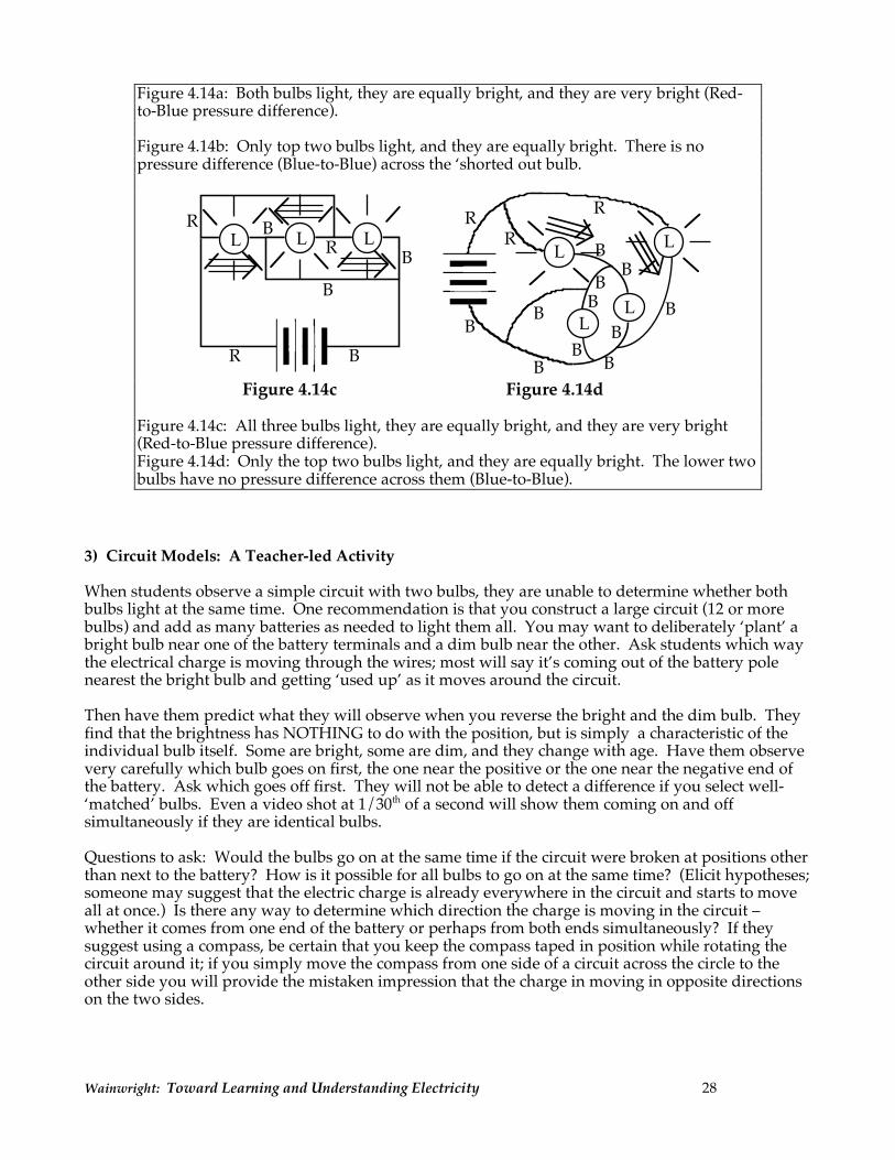
Figure 4.14a: Both bulbs light, they are equally bright, and they are very bright (Red-to-Blue pressure difference). Figure 4.14b: Only top two bulbs light, and they are equally bright. There is no pressure difference (Blue-to-Blue) across the ‘shorted out bulb.
L
L
L LL
LL
B
BB
B
B
B
B
B
B
BB
B
B
B
B
R
R
RR
R
R
Figure 4.14c Figure 4.14d Figure 4.14c: All three bulbs light, they are equally bright, and they are very bright (Red-to-Blue pressure difference). Figure 4.14d: Only the top two bulbs light, and they are equally bright. The lower two bulbs have no pressure difference across them (Blue-to-Blue).
3) Circuit Models: A Teacher-led Activity When students observe a simple circuit with two bulbs, they are unable to determine whether both bulbs light at the same time. One recommendation is that you construct a large circuit (12 or more bulbs) and add as many batteries as needed to light them all. You may want to deliberately ‘plant’ a bright bulb near one of the battery terminals and a dim bulb near the other. Ask students which way the electrical charge is moving through the wires; most will say it’s coming out of the battery pole nearest the bright bulb and getting ‘used up’ as it moves around the circuit. Then have them predict what they will observe when you reverse the bright and the dim bulb. They find that the brightness has NOTHING to do with the position, but is simply a characteristic of the individual bulb itself. Some are bright, some are dim, and they change with age. Have them observe very carefully which bulb goes on first, the one near the positive or the one near the negative end of the battery. Ask which goes off first. They will not be able to detect a difference if you select well-‘matched’ bulbs. Even a video shot at 1/30th of a second will show them coming on and off simultaneously if they are identical bulbs. Questions to ask: Would the bulbs go on at the same time if the circuit were broken at positions other than next to the battery? How is it possible for all bulbs to go on at the same time? (Elicit hypotheses; someone may suggest that the electric charge is already everywhere in the circuit and starts to move all at once.) Is there any way to determine which direction the charge is moving in the circuit – whether it comes from one end of the battery or perhaps from both ends simultaneously? If they suggest using a compass, be certain that you keep the compass taped in position while rotating the circuit around it; if you simply move the compass from one side of a circuit across the circle to the other side you will provide the mistaken impression that the charge in moving in opposite directions on the two sides.
Wainwright: Toward Learning and Understanding Electricity 29
Comparing Two Human Circuit Models: 1. The Circulating Pennies Model: This is a model that is often represented in elementary and middle school textbooks, although it leads to implanting misconceptions. Stand 4 or 5 students in a circle representing light bulbs. Tell them that you, the teacher, acting as a battery, will hand them some charge – represented by a penny. As a penny is placed in their right hand, they raise their left hand to indicate that the light bulb is on. They will pass the penny to the next person/bulb; once the penny is handed off, the the left hand comes down signifying that the bulb has turned off. Advantages of the Model: It suggests that something (charge) moves around a circuit, through light bulbs, and results in bulb lighting. Limitations of the Model: No matter how many charges/pennies are provided by the teacher/battery, there will always be a bulb that lights first in the circuit and a bulb that lights last. Actual circuits do not demonstrate this pattern of behavior. 2. The Hula Hoop Model: Again with 4 or 5 students in a circle, ask them to hold their right hand in a loose ring around a hula hoop. Tell them to lift their left hands high (bulb ‘on’) if they feel the hula hoop moving through their right hand. The teacher is ‘in charge’ and begins to push/pull the hula hoop around in the circle. As soon as it starts in motion, all hands go up; as soon as it stops, all hands go down. (The teacher can also reverse the direction of the hula hoop, and the same results are observed.) Advantages of the Model: It suggests that something (charge) is already in the circuit, and that the teacher/battery simply puts it in motion. When the charge begins to move in the circuit, it moves everywhere at once and all bulbs come on at the same time. The fact that the teacher can reverse the direction of charge flow is analogous to reversing the terminals of a battery in a circuit; it also suggests that bulbs are non-directional – they function equally well with charge moving through them in either direction. Limitations of the Model: Although it is an excellent introductory analogy for simple circuits, the hula hoop model must be substantially modified for discussions of compressible charge in later sections. Note: An important misconception – one held by nearly all students – is that the battery is the sole source of charge in a circuit, squirting it out much like a whipped-cream can. (The term ‘rechargeable’ battery perpetuates that myth, suggesting that the battery becomes empty of charge and therefore must be recharged.) The hula hoop model helps students recognize the possibility that the charge could already exist everywhere in the circuit in which case the battery’s task is not to provide charge but to provide the energy necessary to make it move. You can ask them to consider how you would feel if you had to rotate the hula hoop for hours and hours. They’ll suggest that you’d become very tired, low on energy, and would need to eat to build up your energy, or become ‘re-charged’. (A better name for a ‘rechargeable battery’ would be a ‘re-energizeable battery’.)
Wainwright: Toward Learning and Understanding Electricity 30
APPENDIX C
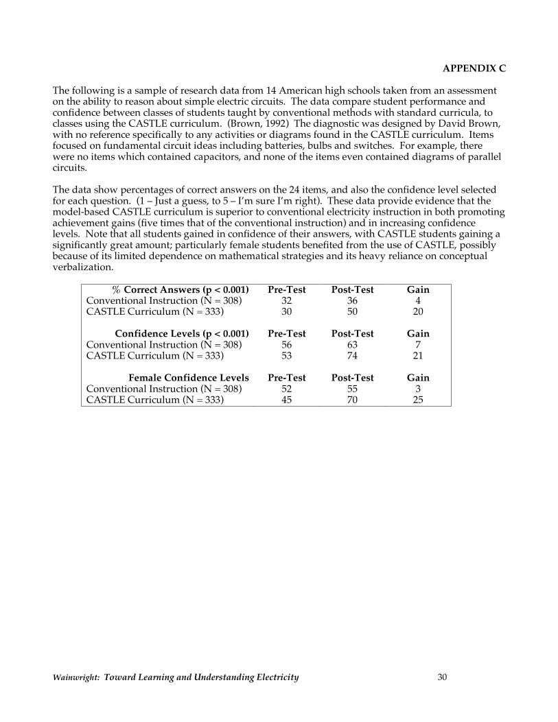
The following is a sample of research data from 14 American high schools taken from an assessment on the ability to reason about simple electric circuits. The data compare student performance and confidence between classes of students taught by conventional methods with standard curricula, to classes using the CASTLE curriculum. (Brown, 1992) The diagnostic was designed by David Brown, with no reference specifically to any activities or diagrams found in the CASTLE curriculum. Items focused on fundamental circuit ideas including batteries, bulbs and switches. For example, there were no items which contained capacitors, and none of the items even contained diagrams of parallel circuits. The data show percentages of correct answers on the 24 items, and also the confidence level selected for each question. (1 – Just a guess, to 5 – I’m sure I’m right). These data provide evidence that the model-based CASTLE curriculum is superior to conventional electricity instruction in both promoting achievement gains (five times that of the conventional instruction) and in increasing confidence levels. Note that all students gained in confidence of their answers, with CASTLE students gaining a significantly great amount; particularly female students benefited from the use of CASTLE, possibly because of its limited dependence on mathematical strategies and its heavy reliance on conceptual verbalization.
% Correct Answers (p < 0.001) Pre-Test Post-Test Gain Conventional Instruction (N = 308) 32 36 4 CASTLE Curriculum (N = 333) 30 50 20
Confidence Levels (p < 0.001) Pre-Test Post-Test Gain Conventional Instruction (N = 308) 56 63 7 CASTLE Curriculum (N = 333) 53 74 21
Female Confidence Levels Pre-Test Post-Test Gain Conventional Instruction (N = 308) 52 55 3 CASTLE Curriculum (N = 333) 45 70 25