tools needed instructions photo
TRANSCRIPT

Document: 19-0201
STEP
4
10mm Wrench 2018+ Trucks Only
Pop the hood. Unlatch the fuse cover panel and remove the fuel pump
fuse at terminal 50.
To relieve fuel pressure, start the engine and allow it to stall. Switch the
vehicle OFF and replace the fuse and panel.
Disconnect the negative battery terminal.
3
10mm Wrench 2015-2017 Trucks Only
Pop the hood. Unlatch the fuse cover panel and remove the fuel pump
fuse. Depending on the model, this can be either at terminal 9 or 56.
To relieve fuel pressure, start the engine and allow it to stall. Switch the
vehicle OFF and replace the fuse and panel.
Disconnect the negative battery terminal.
Support: [email protected]
2
Threadlocker Secure the FST-R to the included bracket using the 4 provided bolts (shown
red) and a medium strength threadlocker.
Using the thumb tabs, unlock and remove the provided flying lead wire
connectors from both the relay and fuse holder. Overlap the fuse holder
and relay mounting tabs placing the relay down first. Secure to the
stainless steel mounting bracket using the provided M5 locking nut and M5
bolt (shown green)
For overflow purposes, the port (shown orange) should be at the top.
4mm Allen Wrench
8mm Wrench
3mm Allen Wrench
The FST-R (sold separately) top cap may need to be properly orientated.
First, remove the 6 perimeter bolts (shown cyan). Next, lift up the top cap
and rotate according to the picture. As a reference, note where the M6
mounting threads (shown red) are located. Finally, tighten bolts making
sure the gasket does not kink.
Replace the preassembled pump outlet fitting with the provided 90 degree
fitting (shown blue) in the kit. To install the pressure gauge (yellow) to the
inline fitting (shown purple), first apply pipe thread paste to the threads.
Screw it finger tight, then add another 1.5 to 3 turns. Finally, install the
inline fitting to the 90 degree fitting on the FST-R.
1
4mm Allen Wrench
3/4" Wrench
7/16" Wrench
Pipe Thread Paste
11/16" Wrench
INSTALLATION INSTRUCTIONSFUEL SURGE TANK KIT
2015+ Ford F150 and Raptor
INSTRUCTIONS PHOTOTOOLS NEEDED
1. It is recommended to work with an empty fuel tank. 2. Working under the vehicle is required. 3. When installing any part which has an O-ring, lubricate with light oil.

6
10mm Socket Find the metal fuel filler tube that is on the opposing side of the fender gas
door. Remove the single M6 bolt that secures the metal fuel filler tube to
the body.
7
7mm Wrench Near the frame rail, loosen the worm drive hose clamp that fastens the
rubber filler hose to the metal filler tube. Slowly drop the tank down until
this fuel fill connection can be pulled apart, as shown. Flat Head Screwdriver
10
Find the electrical fuel pump connector (shown) on the top of the gas tank.
First, slide the red tab to the side to unlock. Next, depress the thumb tab
and pull away to disconnect.
9
Find the electrical connector (shown) on the top rear of the gas tank.
Depress the thumb tab and pull away to disconnect.
8
Find the electrical connector (shown) on the outer LH top side of the gas
tank. Depress the thumb tab and pull away to disconnect.
5
13mm Socket For accessibility, the fuel tank will need to be dropped down.
To remove the skid plate (shown), unfasten the four 13mm hex head nuts
that secure to the 2 fuel tank straps.
Next, support the fuel tank on both ends. Unscrew the fuel tank strap bolts
using a 16mm socket wrench. Unlatch the fuel tank straps (shown) from
the chassis to remove.
16mm Socket

14
Pipe Thread Paste Apply pipe thread paste or tape to the 1/4" NPT threads on the included 90
degree 6AN adapter fitting. Install the fitting in the barbed coupler. Install
finger tight, then add another 1.5 to 3 turns. Ideally the fitting should run
in an upwards direction parallel with the fuel filler tube.
Install the barbed coupler into the center section of the OEM rubber fill
hose and secure using the provided hose clamps.
15mm Wrench
1/4" Socket Wrench
11
Flat Blade Find where the vent line that runs parallel to the fuel filler hose connects to
the tank. Gently pry the green lock up and pull away to disconnect.
12
Flat Blade Find the fuel feed line and EVAP SAE connections. These will be side by
side on top of the front of the gas tank.
For the fuel feed line, gently pry the blue lock up and pull away to
disconnect. Be prepared with a rag as fuel will leak out of this connection.
For the EVAP line, gently squeeze the black side locks and simultaneously
pull away to disconnect.
Rag
15
Find the fuel feed hose connection that was unplugged on the top of the
fuel tank at the very front. This was the smaller of the two fittings that had
the blue SAE quick connect lock. Follow this OEM hard line towards the
front of the truck about 12 inches downstream until you find the next SAE
quick connect with a blue lock. Unlatch this SAE quick connect fitting and
pull. Have a rag handy as fuel will spill.
Remove this short section of OEM fuel hard line (shown) from the truck.
This will NOT be reused.
16
Light Oil Find the two SAE quick connect male fittings provided in the kit. These will
be installed into the fuel feed connection areas from the previous step, ie:
the OEM fuel line from the fuel pump (shown) and the OEM fuel line to the
engine (not shown).
Lubricate the male portion and insert into the OEM SAE female connectors
until a "click" is felt. To secure, push down the blue locks.
13
Hose Cutter The FST overflow port will return fuel into the gas tank via the fuel fill tube.
The included barbed coupler will replace a small cut away section from the
OEM rubber fuel fill hose.
Cut a 1/2" wide section out of the center of the OEM rubber fill hose.
Remember to allow enough room to access the hose end fitting that will be
installed later.

20
Unscrew both ends off the included black Posi-Tap connector. Insert the
OEM yellow/grey stripe power wire (near the fuel pump connector) into
the slotted end of the Posi-Tap connector. Screw the center section back
on making sure the wire gets pierced.
Slide the Posi-Tap collar end piece over the blue wire provided in the kit.
Insert the blue wire into the end of the Posi-tap connector. Finally, smash
the blue wire by tightening the collar end into the Posi-Tap connector, as
shown. See the online Posi-Tap tutorial videos for more detailed
information.
19
Wire Stripper In order to activate the FST-R fuel pump, the included relay will be
triggered from the OEM fuel pump’s power wire. This yellow/grey stripe
wire is found at the end of the connector and is large (AWG) gauge, as
shown.
First, find the included blue wire. Strip the blue insulation back to expose
3/8" of copper.
18
13mm Wrench Lineup the three FST-R bracket holes to the OEM studs and secure the
mount using the provided M8x1.25mm nuts.13mm Socket Wrench
17
M8x1.25mm Die To mount the FST-R, first find the three OEM studs underneath the vehicle.
These will be located on the LH side of the truck, underneath the front
door.
NOTE: These OEM M8x1.25mm studs have body paint on them. The
thickness of the paint may require a rethreading die (shown) to be used for
cleaning the threads.
The included EFI fuel line and various Pusk Lok hose ends will be used to
route the plumbing, as shown. When routing the hoses, be sure to stay
away from moving components such as suspension as well as areas that
get excessively hot.
NOTE: The hose lengths listed in the following steps are only
recommendations. Depending on the vehicle and how the hoses are
exactly plumbed, variations will be present. Measure before cutting and
assembling.
22
21
Diagonal Cutter Route the blue wire along the factory wiring loom. Use the provided cable
zip ties to secure in place, as shown.
26
Diagonal Cutter Route a hose from the inline 6AN gauge adapter over the top of the frame
rail to the forward most Radium SAE male fitting. This is the connection
that routes fuel directly to the engine.
Hose Recommendations:
FST-R Pump Outlet Side Port: 45 Degree Hose End
Radium SAE Female Fitting: 90 Degree Hose End
Hose Cut Length: 18 inches
Oil Lubrication
23
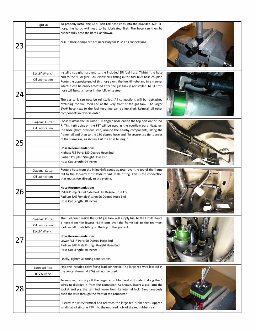
Light Oil To properly install the 6AN Push Lok hose ends into the provided 3/8" EFI
hose, the barbs will need to be lubricated first. The hose can then be
pushed fully onto the barbs, as shown.
NOTE: Hose clamps are not necessary for Push Lok connections.
24
11/16" Wrench Install a straight hose end to the included EFI fuel hose. Tighten the hose
end to the 90 degree 6AN elbow NPT fitting in the fuel filler hose coupler.
Route the opposite end of this hose along the fuel fill tube and in a manner
which it can be easily accessed after the gas tank is reinstalled. NOTE: this
hose will be cut shorter in the following step.
The gas tank can now be reinstalled. All connections will be reattached
excluding the fuel feed line at the very front of the gas tank. The larger
EVAP hose next to the fuel feed line can be installed. Reinstall all other
components in reverse order.
Oil Lubrication
28
Electrical Pick Find the included relay flying lead connector. The large red wire located in
the center (terminal 87A) will not be used.
To remove, first pry off the large red rubber seal and slide it along the 5
wires to dislodge it from the connector. As shown, insert a pick into the
socket and pry the terminal loose from its internal lock. Simultaneously
push the wire through the front of the connector.
Discard the wire/terminal and reattach the large red rubber seal. Apply a
small dab of silicone RTV into the ununsed hole of the red rubber seal.
RTV Slicone
27
Diagonal Cutter The fuel pump inside the OEM gas tank will supply fuel to the FST-R. Route
a hose from the lowest FST-R port over the frame rail to the rearmost
Radium SAE male fitting on the top of the gas tank.
Hose Recommendations:
Lower FST-R Port: 90 Degree Hose End
Radium SAE Male Fitting: Straight Hose End
Hose Cut Length: 30 inches
Finally, tighten all fitting connections.
Oil Lubrication
11/16" Wrench
25
Diagonal Cutter Loosely install the included 180 degree hose end to the top port on the FST-
R. This high point on the FST will be used as the overflow port. Next, run
the hose (from previous step) around the nearby components, along the
frame rail and then to the 180 degree hose end. To secure, zip tie to areas
of the frame rail, as shown. Cut the hose to length.
Hose Recommendations:
Highest FST Port: 180 Degree Hose End
Barbed Coupler: Straight Hose End
Hose Cut Length: 94 inches
Oil Lubrication
34
3/8" Open End Wrench The FST-R is NOT set to a specific pressure. To increase pressure, tighten
set screw. To reduce pressure, loosen set screw. Adjust the FST-R to the
desired pressure. OEM 3.5L GTDi fuel pressure is 58-75psi (400-520 kPA).
Consult with your tuner before setting the fuel pressure. Once adjusted,
lock the set screw in place with the jam nut.
NOTES: 1. Do NOT connect a vacuum hose to the fuel pressure regulator
nipple unless a 1:1 rising rate is required. 2. The extra orifice is not
required unless minimum static fuel pressure cannot be achieved.
INSTALLATION COMPLETE
3/32" Allen Wrench
33
Temporarily remove the new fuel pump fuse and reconnect the negative
battery terminal.
Switch the ignition to the ON position a few times without starting the
engine. This will prime the OEM fuel pump and fill the FST-R. Check for
leaks and fix any that may have occurred. Reinstall the fuse.
It may take longer than usual to start the engine as air pockets are being
bled from the system. Start and idle the engine. Re-check for leaks.
32
13mm Socket Secure the large chassis ground ring terminal to one of the OEM M8 studs
that mounts the Radium Engineering bracket. It may be necessary to
remove some paint to expose bare metal for a good electrical contact.
Using the included split wire loom for protection, route the red power wire
to the battery safely avoiding hot areas or any sharp edges that could
cause unwanted chaffing. Connect the small power ring terminal to the M6
positive battery terminal, as shown.
Use the cable zip ties included to secure the wire loom in place.
Diagonal Cutter
11mm Socket
31
Heat Gun Note the different locations of the included solder butt connectors in the
wiring schematic diagram above. There are 4 solder butt connectors.
To properly use the solder butt connectors, strip each wire insulation back
and insert both wires into the butt connector ends. Use a heat gun. Be
careful with the surrounding area as the internal solder may take a couple
minutes to melt. Verify the connection is solid by giving it a tug.
30
Wire Cutters Assemble the components as shown in the wiring schematic (not to scale).
Cut all wires to length.
NOTE:
1. For strain relief, always allow slack in the wire so it does not pull.
2. There are 2 slotted holes in the stainless steel mounting bracket
specifically to keep the relay and fuse wires secured with a cable zip-tie.
Wire Strippers
Wire Crimpers
29
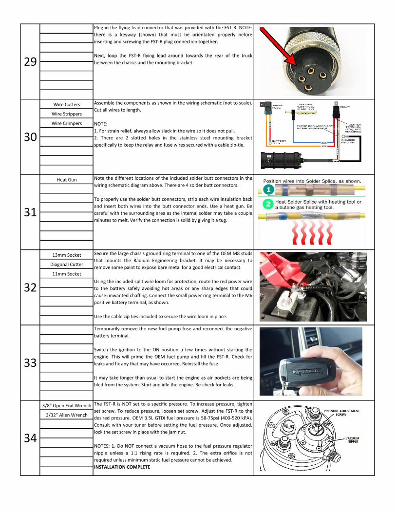
Plug in the flying lead connector that was provided with the FST-R. NOTE:
there is a keyway (shown) that must be orientated properly before
inserting and screwing the FST-R plug connection together.
Next, loop the FST-R flying lead around towards the rear of the truck
between the chassis and the mounting bracket.