toolbuilder programmer’s reference - cognex note...toolbuilder programmer’s reference ... vb.net...
TRANSCRIPT
ToolBuilder Programmer’s Reference Integration Note
Author: Samantha Frost
Product Marketing
Published: February 2011
Integration Note
Contents
TOOLBUILDER PROGRAMMER’S REFERENCE ...................................................................................... 1 Overview ............................................................................................................................................... 3 Prerequisites ......................................................................................................................................... 3 Development System Requirements .................................................................................................... 3 Related Files ......................................................................................................................................... 3 EasyBuilder Tool Development ............................................................................................................ 5 Spreadsheet Syntax & EZTag Specification ...................................................................................... 11 Publishing Spreadsheet Data to the EasyBuilder Application ............................................................ 34 Appendix A ......................................................................................................................................... 41 Appendix B: ToolBuilder Deployment Example – VB.NET ................................................................ 42 Appendix C: ToolBuilder Deployment Example – C# ......................................................................... 46
Cognex Corporation Page 2 of 50

Integration Note
Overview The purpose of this document is to provide a programmer with detailed information needed to create an EasyBuilder Tool. This document will cover EasyBuilder Tool Development, Spreadsheet Syntax and EZTag Specifications, and Publishing the tool in EasyBuilder using the EasyBuilderToolMgr Class API.
With this document, a developer should be able to:
1. Create a new EasyBuilder Tool in the In-Sight spreadsheet environment. 2. Expose parameters of the EasyBuilder Tool to the EasyBuilder user interface and communication
systems. 3. Create the EasyTags needed to expose additional attributes of the EasyBuilder Tool to the
EasyBuilder application development environment. 4. Create a C# or VB.NET DLL needed to register and publish the new EasyBuilder Tool for us in
EasyBuilder.
This document has been updated to include all current EZTags in ISE 4.4.1.
Prerequisites Creating an EasyBuilder tool requires advanced knowledge of spreadsheet programming.
Creating a tool requires some experience with .Net programming, and specifically use of Microsoft Developer Studio 2005 or 2008.
Development System Requirements In order to use tools created using the Toolbuilder reference in a newer version of ISE, the programmer must recompile their code with the new version of SDK that matches ISE. For example: Use 4.5 SDK to deploy and use tools in ISE 4.5. Do not mix SDK dlls and ISE versions.
In addition also make sure that when building the DLL it is targeted to the "x86" platform using the .Net 2.0 framework.
1. .Net Framework 2.0
2. Visual Studio 2005 or 2008, VB.NET / C# Note: you can download and use the free version of Visual Studio 2008 Express, available at the following link: http://www.microsoft.com/express/Downloads/
3. GUID Generation Utility: guidgen.exe located (for VS 2008) in: C:\Program Files\Microsoft Visual Studio 9\Common7\Tools
4. Cognex In-Sight SDK license
5. For a complete list of system requirements, see Appendix A, or view the following link: http://msdn2.microsoft.com/en-us/express/aa718403.aspx
Related Files EasyBuilder tool templates are included with the snippets installed with ISE. These examples provide a spreadsheet template for creating EasyBuilder Tools and Results. The templates are located under
Cognex Corporation Page 3 of 50

Integration Note
Snippets->EasyBuilder category in the ISE Palette.
Cognex Corporation Page 4 of 50
Integration Note
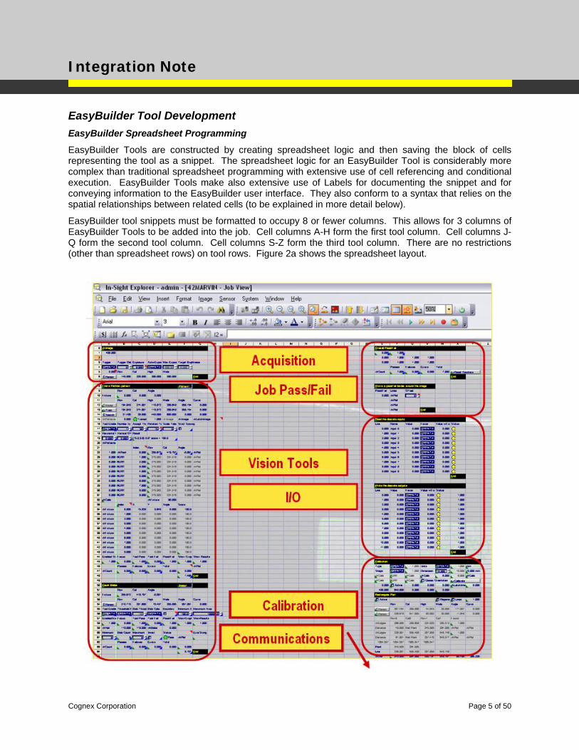
EasyBuilder Tool Development EasyBuilder Spreadsheet Programming
EasyBuilder Tools are constructed by creating spreadsheet logic and then saving the block of cells representing the tool as a snippet. The spreadsheet logic for an EasyBuilder Tool is considerably more complex than traditional spreadsheet programming with extensive use of cell referencing and conditional execution. EasyBuilder Tools make also extensive use of Labels for documenting the snippet and for conveying information to the EasyBuilder user interface. They also conform to a syntax that relies on the spatial relationships between related cells (to be explained in more detail below).
EasyBuilder tool snippets must be formatted to occupy 8 or fewer columns. This allows for 3 columns of EasyBuilder Tools to be added into the job. Cell columns A-H form the first tool column. Cell columns J-Q form the second tool column. Cell columns S-Z form the third tool column. There are no restrictions (other than spreadsheet rows) on tool rows. Figure 2a shows the spreadsheet layout.
Cognex Corporation Page 5 of 50
Integration Note
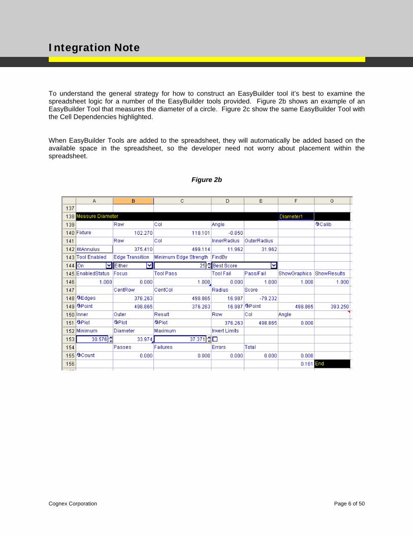
To understand the general strategy for how to construct an EasyBuilder tool it’s best to examine the spreadsheet logic for a number of the EasyBuilder tools provided. Figure 2b shows an example of an EasyBuilder Tool that measures the diameter of a circle. Figure 2c show the same EasyBuilder Tool with the Cell Dependencies highlighted.
When EasyBuilder Tools are added to the spreadsheet, they will automatically be added based on the available space in the spreadsheet, so the developer need not worry about placement within the spreadsheet.
Figure 2b
Cognex Corporation Page 6 of 50

Integration Note
Figure 2c
Cognex Corporation Page 7 of 50
Integration Note
Regions of Interest
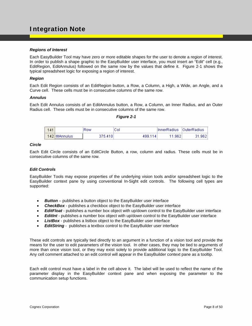
Each EasyBuilder Tool may have zero or more editable shapes for the user to denote a region of interest. In order to publish a shape graphic to the EasyBuilder user interface, you must insert an “Edit” cell (e.g., EditRegion, EditAnnulus) followed on the same row by the values that define it. Figure 2-1 shows the typical spreadsheet logic for exposing a region of interest.
Region
Each Edit Region consists of an EditRegion button, a Row, a Column, a High, a Wide, an Angle, and a Curve cell. These cells must be in consecutive columns of the same row.
Annulus
Each Edit Annulus consists of an EditAnnulus button, a Row, a Column, an Inner Radius, and an Outer Radius cell. These cells must be in consecutive columns of the same row.
Figure 2-1
Circle
Each Edit Circle consists of an EditCircle Button, a row, column and radius. These cells must be in consecutive columns of the same row.
Edit Controls
EasyBuilder Tools may expose properties of the underlying vision tools and/or spreadsheet logic to the EasyBuilder context pane by using conventional In-Sight edit controls. The following cell types are supported:
• Button – publishes a button object to the EasyBuilder user interface • CheckBox - publishes a checkbox object to the EasyBuilder user interface • EditFloat - publishes a number box object with up/down control to the EasyBuilder user interface • EditInt - publishes a number box object with up/down control to the EasyBuilder user interface • ListBox - publishes a listbox object to the EasyBuilder user interface • EditString - publishes a textbox control to the EasyBuilder user interface
These edit controls are typically tied directly to an argument in a function of a vision tool and provide the means for the user to edit parameters of the vision tool. In other cases, they may be tied to arguments of more than once vision tool, or they may exist solely to provide additional logic to the EasyBuilder Tool. Any cell comment attached to an edit control will appear in the EasyBuilder context pane as a tooltip.
Each edit control must have a label in the cell above it. The label will be used to reflect the name of the parameter display in the EasyBuilder context pane and when exposing the parameter to the communication setup functions.
Cognex Corporation Page 8 of 50
Integration Note
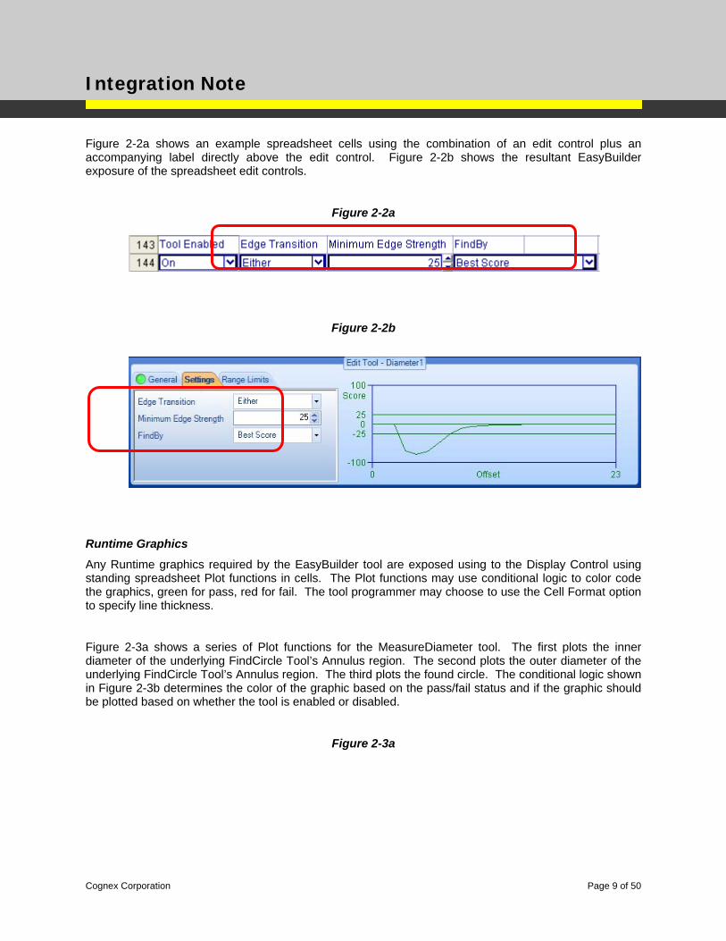
Figure 2-2a shows an example spreadsheet cells using the combination of an edit control plus an accompanying label directly above the edit control. Figure 2-2b shows the resultant EasyBuilder exposure of the spreadsheet edit controls.
Figure 2-2a
Figure 2-2b
Runtime Graphics
Any Runtime graphics required by the EasyBuilder tool are exposed using to the Display Control using standing spreadsheet Plot functions in cells. The Plot functions may use conditional logic to color code the graphics, green for pass, red for fail. The tool programmer may choose to use the Cell Format option to specify line thickness.
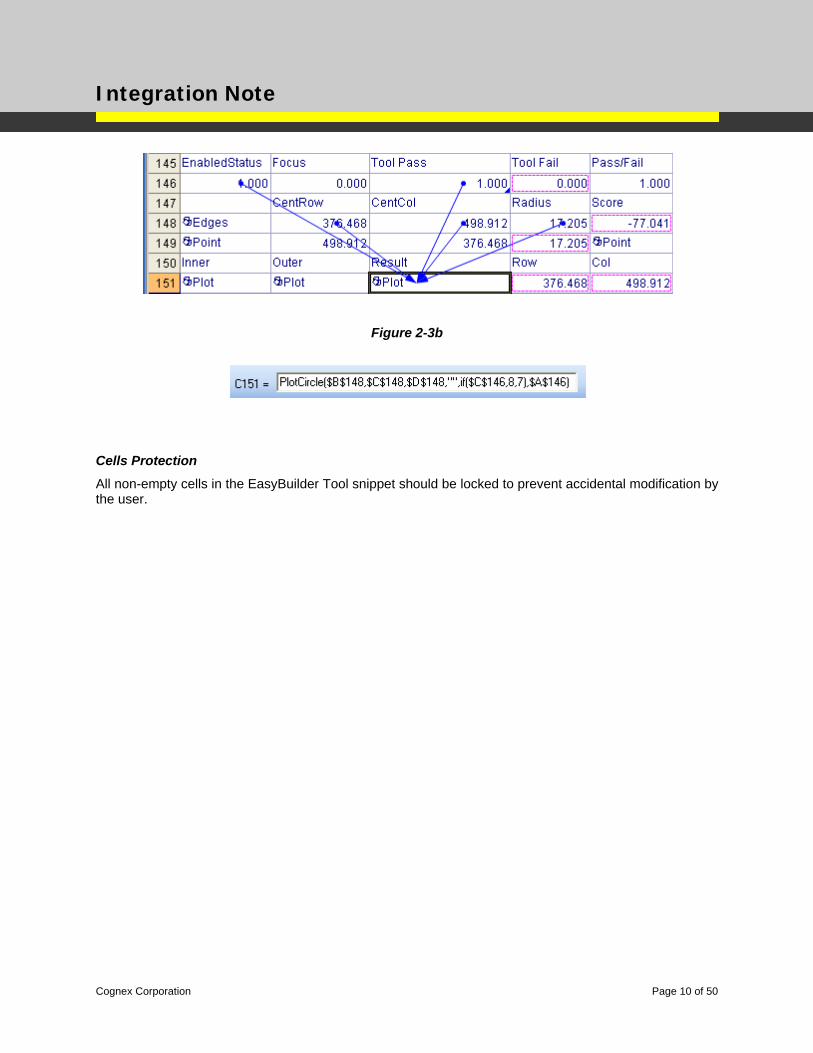
Figure 2-3a shows a series of Plot functions for the MeasureDiameter tool. The first plots the inner diameter of the underlying FindCircle Tool’s Annulus region. The second plots the outer diameter of the underlying FindCircle Tool’s Annulus region. The third plots the found circle. The conditional logic shown in Figure 2-3b determines the color of the graphic based on the pass/fail status and if the graphic should be plotted based on whether the tool is enabled or disabled.
Figure 2-3a
Cognex Corporation Page 9 of 50
Integration Note
Figure 2-3b
Cells Protection
All non-empty cells in the EasyBuilder Tool snippet should be locked to prevent accidental modification by the user.
Cognex Corporation Page 10 of 50
Integration Note
Spreadsheet Syntax & EZTag Specification EZTags are used to identify “interesting” cells in the EasyBuilder Tool. An EZTag is simply a special comment that is accessed by the EasyBuilder application for two primary purposes – GUI formatting, and cell referencing / linking. Some EZTags are used to convey information to the EasyBuilder context panes, while others are used to allow the EasyBuilder application to create cell references between EasyBuilder Tools and other aspects of the EasyBuilder job. For example, cell references for fixturing, calibration and global pass/fail status information are all managed by the EasyBuilder application using the EZTags.
Once the EasyBuilder Tool has been added to the spreadsheet, the EasyBuilder application will parse the spreadsheet logic searching for the EZTags that help define the behavior of the tool.
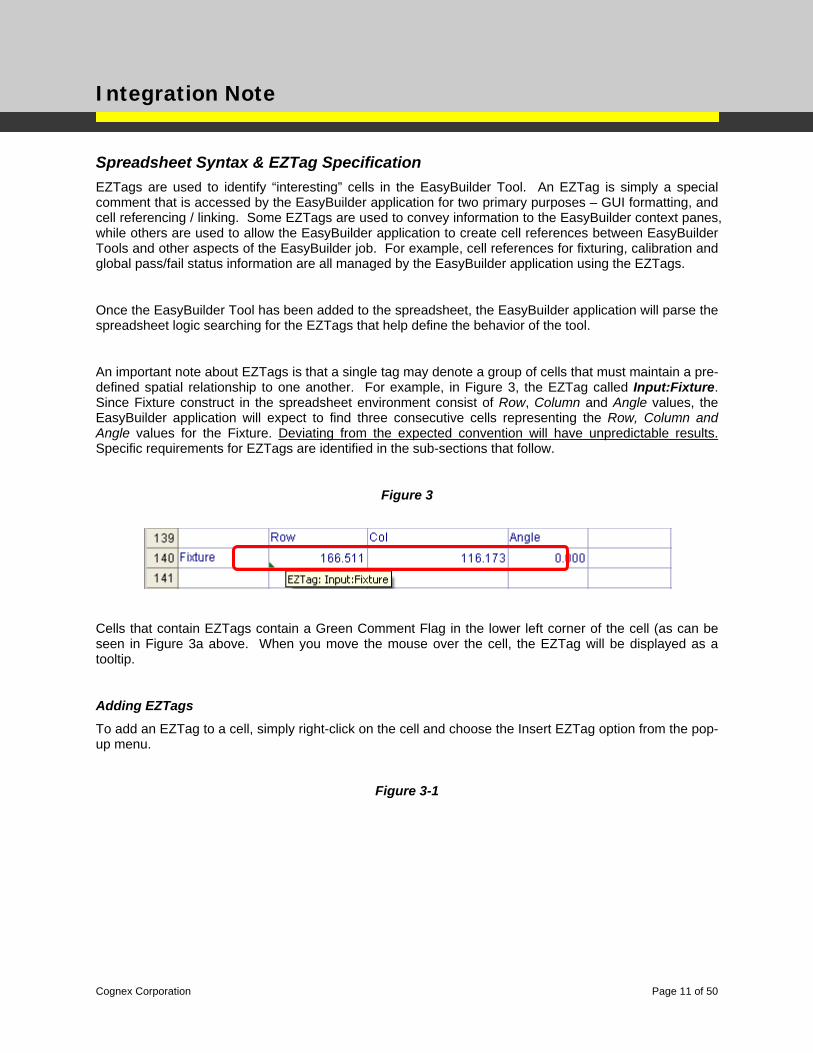
An important note about EZTags is that a single tag may denote a group of cells that must maintain a pre-defined spatial relationship to one another. For example, in Figure 3, the EZTag called Input:Fixture. Since Fixture construct in the spreadsheet environment consist of Row, Column and Angle values, the EasyBuilder application will expect to find three consecutive cells representing the Row, Column and Angle values for the Fixture. Deviating from the expected convention will have unpredictable results. Specific requirements for EZTags are identified in the sub-sections that follow.
Figure 3
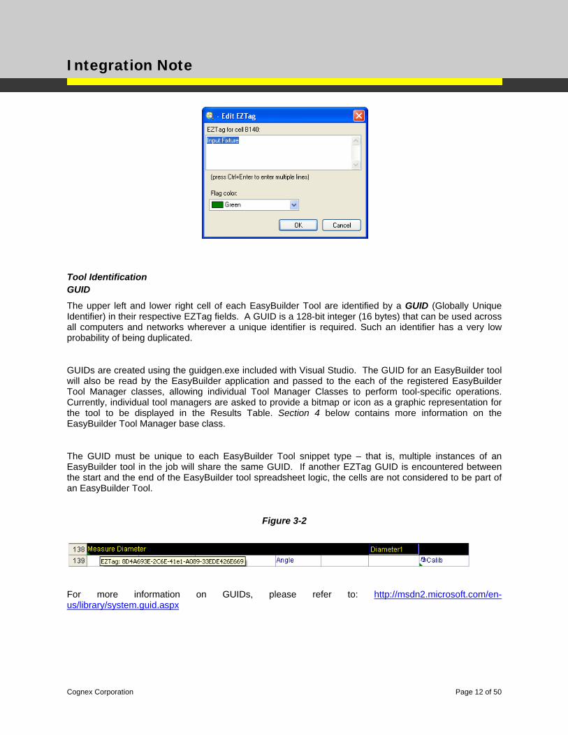
Cells that contain EZTags contain a Green Comment Flag in the lower left corner of the cell (as can be seen in Figure 3a above. When you move the mouse over the cell, the EZTag will be displayed as a tooltip.
Adding EZTags
To add an EZTag to a cell, simply right-click on the cell and choose the Insert EZTag option from the pop-up menu.
Figure 3-1
Cognex Corporation Page 11 of 50
Integration Note
Tool Identification GUID
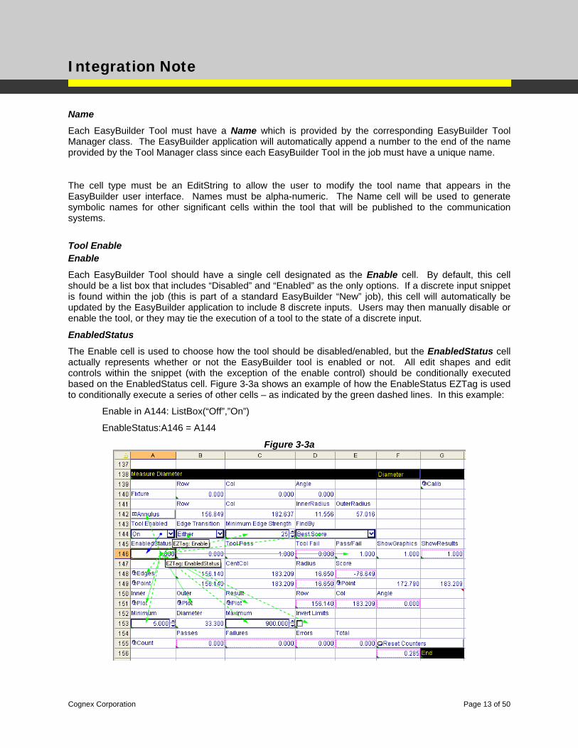
The upper left and lower right cell of each EasyBuilder Tool are identified by a GUID (Globally Unique Identifier) in their respective EZTag fields. A GUID is a 128-bit integer (16 bytes) that can be used across all computers and networks wherever a unique identifier is required. Such an identifier has a very low probability of being duplicated.
GUIDs are created using the guidgen.exe included with Visual Studio. The GUID for an EasyBuilder tool will also be read by the EasyBuilder application and passed to the each of the registered EasyBuilder Tool Manager classes, allowing individual Tool Manager Classes to perform tool-specific operations. Currently, individual tool managers are asked to provide a bitmap or icon as a graphic representation for the tool to be displayed in the Results Table. Section 4 below contains more information on the EasyBuilder Tool Manager base class.
The GUID must be unique to each EasyBuilder Tool snippet type – that is, multiple instances of an EasyBuilder tool in the job will share the same GUID. If another EZTag GUID is encountered between the start and the end of the EasyBuilder tool spreadsheet logic, the cells are not considered to be part of an EasyBuilder Tool.
Figure 3-2
For more information on GUIDs, please refer to: http://msdn2.microsoft.com/en-us/library/system.guid.aspx
Cognex Corporation Page 12 of 50
Integration Note
Name
Each EasyBuilder Tool must have a Name which is provided by the corresponding EasyBuilder Tool Manager class. The EasyBuilder application will automatically append a number to the end of the name provided by the Tool Manager class since each EasyBuilder Tool in the job must have a unique name.
The cell type must be an EditString to allow the user to modify the tool name that appears in the EasyBuilder user interface. Names must be alpha-numeric. The Name cell will be used to generate symbolic names for other significant cells within the tool that will be published to the communication systems.
Tool Enable Enable
Each EasyBuilder Tool should have a single cell designated as the Enable cell. By default, this cell should be a list box that includes “Disabled” and “Enabled” as the only options. If a discrete input snippet is found within the job (this is part of a standard EasyBuilder “New” job), this cell will automatically be updated by the EasyBuilder application to include 8 discrete inputs. Users may then manually disable or enable the tool, or they may tie the execution of a tool to the state of a discrete input.
EnabledStatus
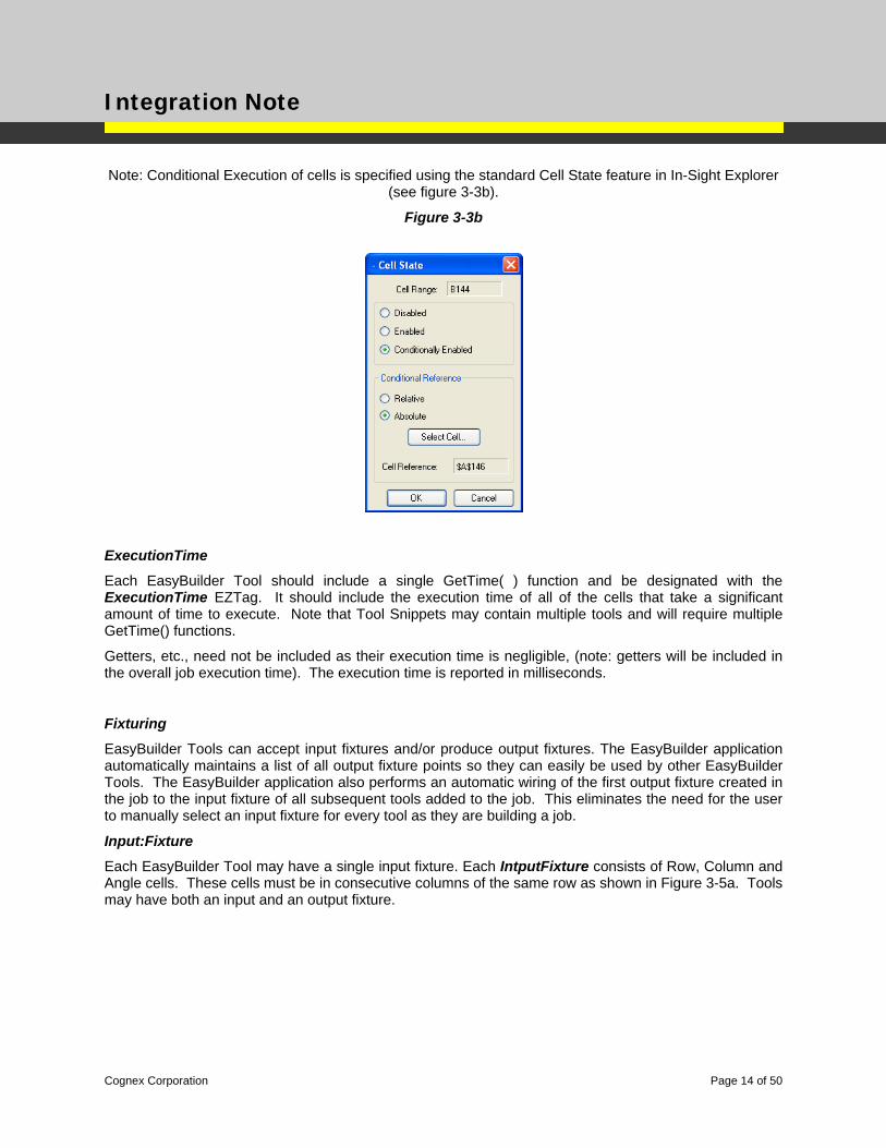
The Enable cell is used to choose how the tool should be disabled/enabled, but the EnabledStatus cell actually represents whether or not the EasyBuilder tool is enabled or not. All edit shapes and edit controls within the snippet (with the exception of the enable control) should be conditionally executed based on the EnabledStatus cell. Figure 3-3a shows an example of how the EnableStatus EZTag is used to conditionally execute a series of other cells – as indicated by the green dashed lines. In this example:
Enable in A144: ListBox(“Off”,”On”)
EnableStatus:A146 = A144
Figure 3-3a
Cognex Corporation Page 13 of 50
Integration Note
Note: Conditional Execution of cells is specified using the standard Cell State feature in In-Sight Explorer (see figure 3-3b).
Figure 3-3b
ExecutionTime
Each EasyBuilder Tool should include a single GetTime( ) function and be designated with the ExecutionTime EZTag. It should include the execution time of all of the cells that take a significant amount of time to execute. Note that Tool Snippets may contain multiple tools and will require multiple GetTime() functions.
Getters, etc., need not be included as their execution time is negligible, (note: getters will be included in the overall job execution time). The execution time is reported in milliseconds.
Fixturing
EasyBuilder Tools can accept input fixtures and/or produce output fixtures. The EasyBuilder application automatically maintains a list of all output fixture points so they can easily be used by other EasyBuilder Tools. The EasyBuilder application also performs an automatic wiring of the first output fixture created in the job to the input fixture of all subsequent tools added to the job. This eliminates the need for the user to manually select an input fixture for every tool as they are building a job.
Input:Fixture
Each EasyBuilder Tool may have a single input fixture. Each IntputFixture consists of Row, Column and Angle cells. These cells must be in consecutive columns of the same row as shown in Figure 3-5a. Tools may have both an input and an output fixture.
Cognex Corporation Page 14 of 50
Integration Note
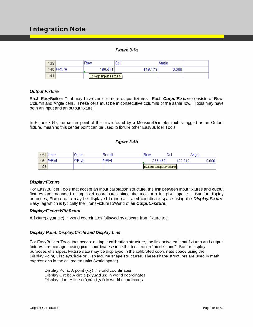
Figure 3-5a
Output:Fixture
Each EasyBuilder Tool may have zero or more output fixtures. Each OutputFixture consists of Row, Column and Angle cells. These cells must be in consecutive columns of the same row. Tools may have both an input and an output fixture.
In Figure 3-5b, the center point of the circle found by a MeasureDiameter tool is tagged as an Output fixture, meaning this center point can be used to fixture other EasyBuilder Tools.
Figure 3-5b
Display:Fixture
For EasyBuilder Tools that accept an input calibration structure, the link between input fixtures and output fixtures are managed using pixel coordinates since the tools run in “pixel space”. But for display purposes, Fixture data may be displayed in the calibrated coordinate space using the Display:Fixture EasyTag which is typically the TransFixtureToWorld of an Output:Fixture.
Display:FixtureWithScore
A fixture(x,y,angle) in world coordinates followed by a score from fixture tool.
Display:Point, Display:Circle and Display:Line For EasyBuilder Tools that accept an input calibration structure, the link between input fixtures and output fixtures are managed using pixel coordinates since the tools run in “pixel space”. But for display purposes of shapes, Fixture data may be displayed in the calibrated coordinate space using the Display:Point, Display:Circle or Display:Line shape structures. These shape structures are used in math expressions in the calibrated units (world space)
Display:Point: A point (x,y) in world coordinates Display:Circle: A circle (x,y,radius) in world coordinates Display:Line: A line (x0,y0,x1,y1) in world coordinates
Cognex Corporation Page 15 of 50
Integration Note
Pass/Fail Status Information Pass/Fail
Each EasyBuilder Tool should have a cell identified as the Pass /Fail cell. This cell must be a value of one when the tool is passing and zero when the tool is failing. This cell will automatically get AND’ed together with the Pass /Fail cells from the other tools to form an overall job pass/fail status. This cell should be dependent on the EnabledStatus cell the value should always be one when the tool is disabled. This will keep disabled tools from affecting the overall pass/fail. This cell should reflect the current pass/fail state of the tool regardless of the tool’s EnabledStatus. Editing a disabled tool is allowed and this cell should reflect the pass/fail state of the tool.
For example, the following properties are all related as follows:
Tool Enable: A4=ListBox(“Off”,”On”)
EnabledStatus: A5=A4
Tool Pass: A6=???
Tool Fail: A7=Not(A6)
IncludeInJobPass: A8=CheckBox(…)
Pass: A9=A6 || Not(A5) || Not(A8)
Status: A10=if(A6,1,2)
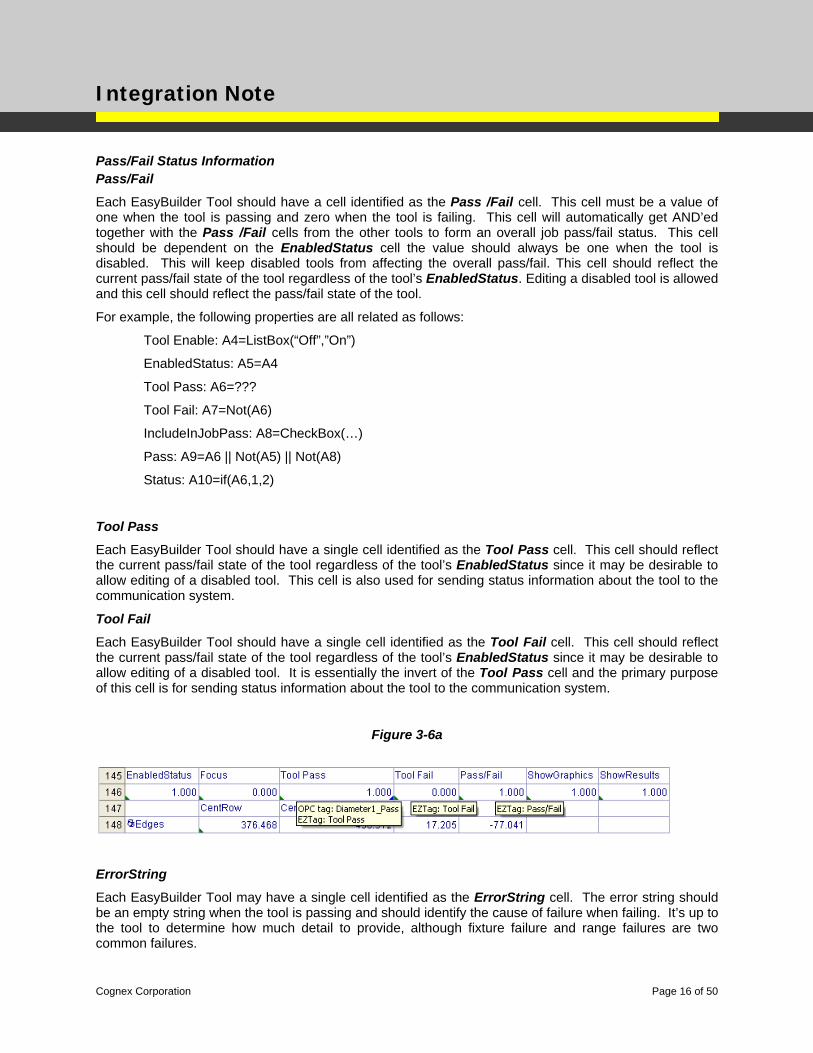
Tool Pass
Each EasyBuilder Tool should have a single cell identified as the Tool Pass cell. This cell should reflect the current pass/fail state of the tool regardless of the tool’s EnabledStatus since it may be desirable to allow editing of a disabled tool. This cell is also used for sending status information about the tool to the communication system.
Tool Fail
Each EasyBuilder Tool should have a single cell identified as the Tool Fail cell. This cell should reflect the current pass/fail state of the tool regardless of the tool’s EnabledStatus since it may be desirable to allow editing of a disabled tool. It is essentially the invert of the Tool Pass cell and the primary purpose of this cell is for sending status information about the tool to the communication system.
Figure 3-6a
ErrorString
Each EasyBuilder Tool may have a single cell identified as the ErrorString cell. The error string should be an empty string when the tool is passing and should identify the cause of failure when failing. It’s up to the tool to determine how much detail to provide, although fixture failure and range failures are two common failures.
Cognex Corporation Page 16 of 50
Integration Note
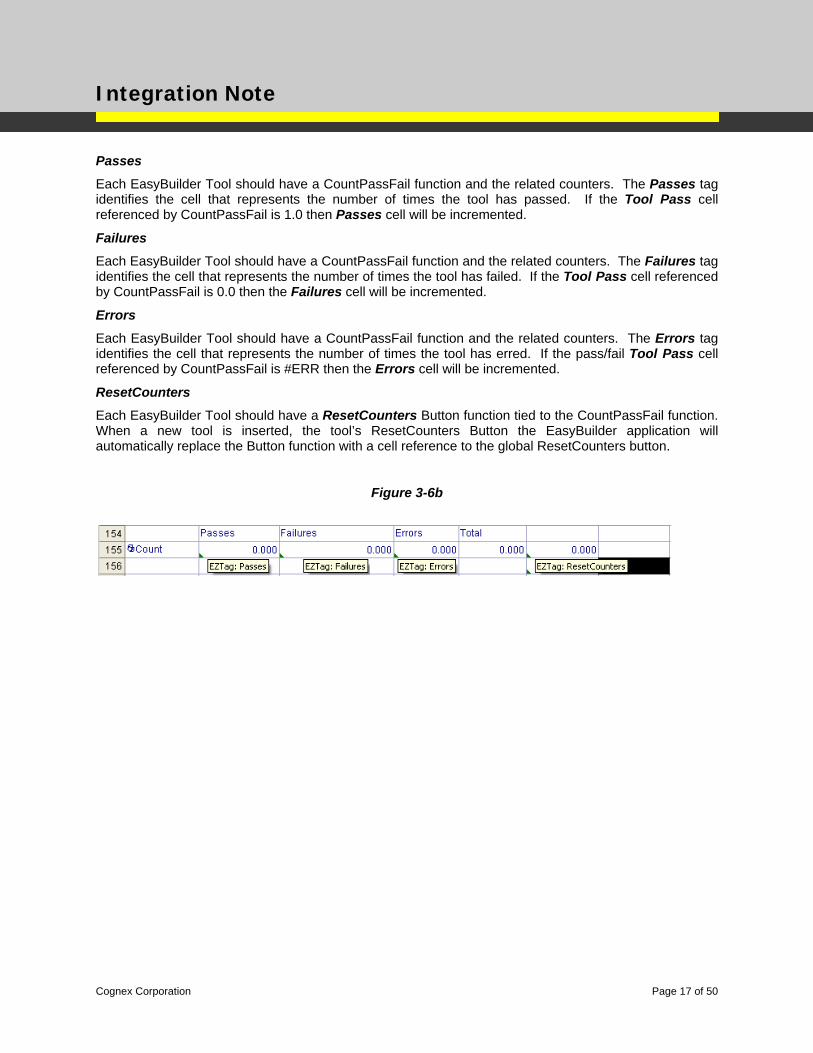
Passes
Each EasyBuilder Tool should have a CountPassFail function and the related counters. The Passes tag identifies the cell that represents the number of times the tool has passed. If the Tool Pass cell referenced by CountPassFail is 1.0 then Passes cell will be incremented.
Failures
Each EasyBuilder Tool should have a CountPassFail function and the related counters. The Failures tag identifies the cell that represents the number of times the tool has failed. If the Tool Pass cell referenced by CountPassFail is 0.0 then the Failures cell will be incremented.
Errors
Each EasyBuilder Tool should have a CountPassFail function and the related counters. The Errors tag identifies the cell that represents the number of times the tool has erred. If the pass/fail Tool Pass cell referenced by CountPassFail is #ERR then the Errors cell will be incremented.
ResetCounters
Each EasyBuilder Tool should have a ResetCounters Button function tied to the CountPassFail function. When a new tool is inserted, the tool’s ResetCounters Button the EasyBuilder application will automatically replace the Button function with a cell reference to the global ResetCounters button.
Figure 3-6b
Cognex Corporation Page 17 of 50
Integration Note
Range Limits
EasyBuilder Tools that produce measurement data generally have Range Limits associated with the tool so the tool can product a Pass/Fail status value. The EasyBuilderToolMgr class can evaluate the initial result/value produced by the EasyBuilder Tool and automatically assign Smart Limits to the range limit cells.
As an example, for an EasyBuilder Tool that measures a distance, the minimum and maximum range limits could be set to +/- 5% of the initial measured value. Or for an EasyBuilder Tool that counts blobs, the minimum and maximum range limits could set to the number of found blobs. Section 4 below contains more information on the EasyBuilder Tool Manager base class.
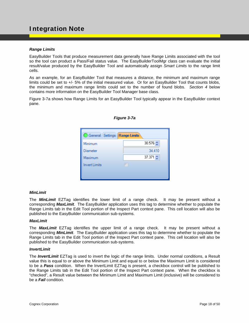
Figure 3-7a shows how Range Limits for an EasyBuilder Tool typically appear in the EasyBuilder context pane.
Figure 3-7a
MinLimit
The MinLimit EZTag identifies the lower limit of a range check. It may be present without a corresponding MaxLimit. The EasyBuilder application uses this tag to determine whether to populate the Range Limits tab in the Edit Tool portion of the Inspect Part context pane. This cell location will also be published to the EasyBuilder communication sub-systems.
MaxLimit
The MaxLimit EZTag identifies the upper limit of a range check. It may be present without a corresponding MinLimit. The EasyBuilder application uses this tag to determine whether to populate the Range Limits tab in the Edit Tool portion of the Inspect Part context pane. This cell location will also be published to the EasyBuilder communication sub-systems.
InvertLimit
The InvertLimit EZTag is used to invert the logic of the range limits. Under normal conditions, a Result value this is equal to or above the Minimum Limit and equal to or below the Maximum Limit is considered to be a Pass condition. When the InvertLimit EZTag is present, a checkbox control will be published to the Range Limits tab in the Edit Tool portion of the Inspect Part context pane. When the checkbox is “checked”, a Result value between the Minimum Limit and Maximum Limit (inclusive) will be considered to be a Fail condition.
Cognex Corporation Page 18 of 50
Integration Note
Figure 3-7b
Output Shapes
EasyBuilder Tools may generate zero or more shapes. These shapes may be used as inputs to other EasyBuilder Tools. For example, two circle finding tools will each generate an output circle that may then be used as inputs to a concentricity tool. The units for all output shapes must be in pixels.
Output:Point
An EZTag designated as an Output:Point denotes 2 adjacent cells in the spreadsheet. A point consists of a Row and a Column cell. These cells must be in consecutive columns of the same row in the spreadsheet. Output:Point must be in the pixel space.
Figure 3-8a
Output:PointStatus
An EZTag that is similar in structure to the Output:Point EZTag except it needs an additional reference to one cell to determine the color of the graphic (negative=fail, 0=warn, positive=pass)
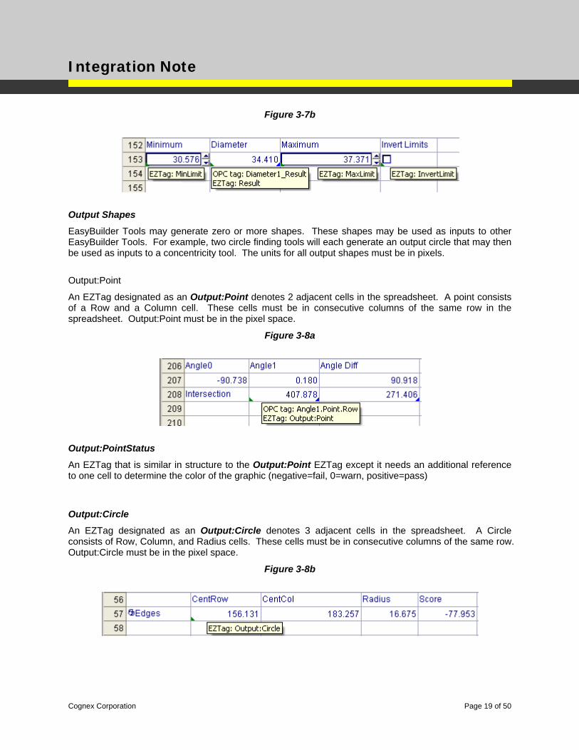
Output:Circle
An EZTag designated as an Output:Circle denotes 3 adjacent cells in the spreadsheet. A Circle consists of Row, Column, and Radius cells. These cells must be in consecutive columns of the same row. Output:Circle must be in the pixel space.
Figure 3-8b
Cognex Corporation Page 19 of 50
Integration Note
Output:CircleStatus
An EZTag that is similar in structure to the Output:Circle EZTag except it needs an additional reference to one cell to determine the color of the graphic (negative=fail, 0=warn, positive=pass)
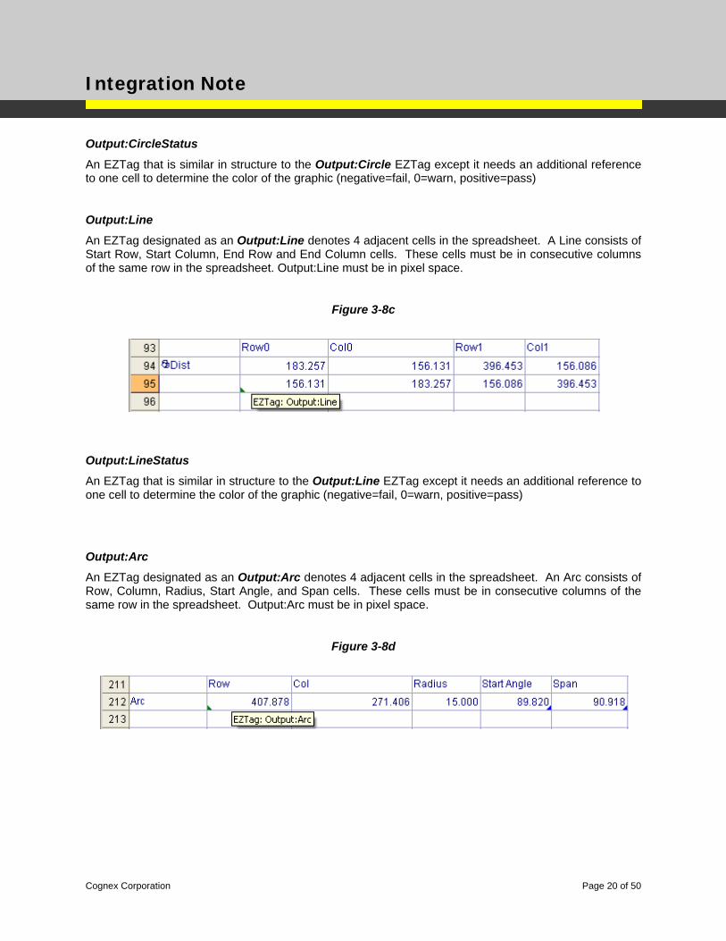
Output:Line
An EZTag designated as an Output:Line denotes 4 adjacent cells in the spreadsheet. A Line consists of Start Row, Start Column, End Row and End Column cells. These cells must be in consecutive columns of the same row in the spreadsheet. Output:Line must be in pixel space.
Figure 3-8c
Output:LineStatus
An EZTag that is similar in structure to the Output:Line EZTag except it needs an additional reference to one cell to determine the color of the graphic (negative=fail, 0=warn, positive=pass)
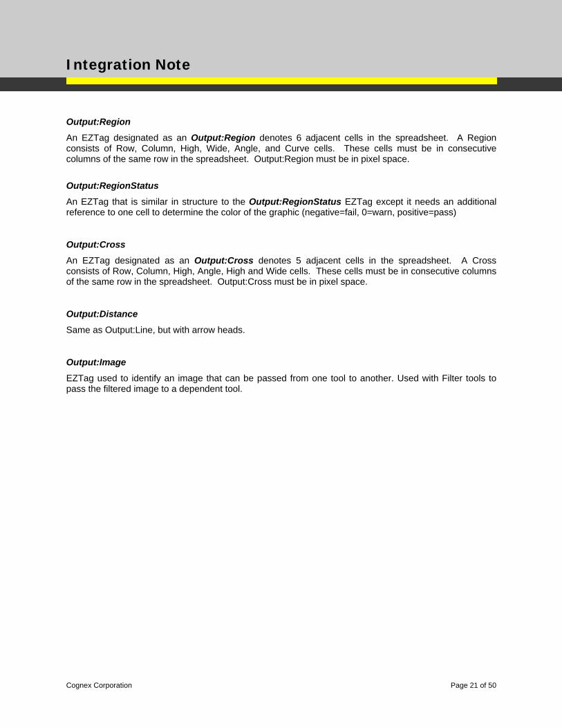
Output:Arc
An EZTag designated as an Output:Arc denotes 4 adjacent cells in the spreadsheet. An Arc consists of Row, Column, Radius, Start Angle, and Span cells. These cells must be in consecutive columns of the same row in the spreadsheet. Output:Arc must be in pixel space.
Figure 3-8d
Cognex Corporation Page 20 of 50
Integration Note
Output:Region
An EZTag designated as an Output:Region denotes 6 adjacent cells in the spreadsheet. A Region consists of Row, Column, High, Wide, Angle, and Curve cells. These cells must be in consecutive columns of the same row in the spreadsheet. Output:Region must be in pixel space.
Output:RegionStatus
An EZTag that is similar in structure to the Output:RegionStatus EZTag except it needs an additional reference to one cell to determine the color of the graphic (negative=fail, 0=warn, positive=pass)
Output:Cross
An EZTag designated as an Output:Cross denotes 5 adjacent cells in the spreadsheet. A Cross consists of Row, Column, High, Angle, High and Wide cells. These cells must be in consecutive columns of the same row in the spreadsheet. Output:Cross must be in pixel space.
Output:Distance
Same as Output:Line, but with arrow heads.
Output:Image
EZTag used to identify an image that can be passed from one tool to another. Used with Filter tools to pass the filtered image to a dependent tool.
Cognex Corporation Page 21 of 50
Integration Note
Input Shapes
EasyBuilder Tools may require zero or more shapes. EasyBuilder will tie these shape inputs to the shape outputs of other EasyBuilder Tools.
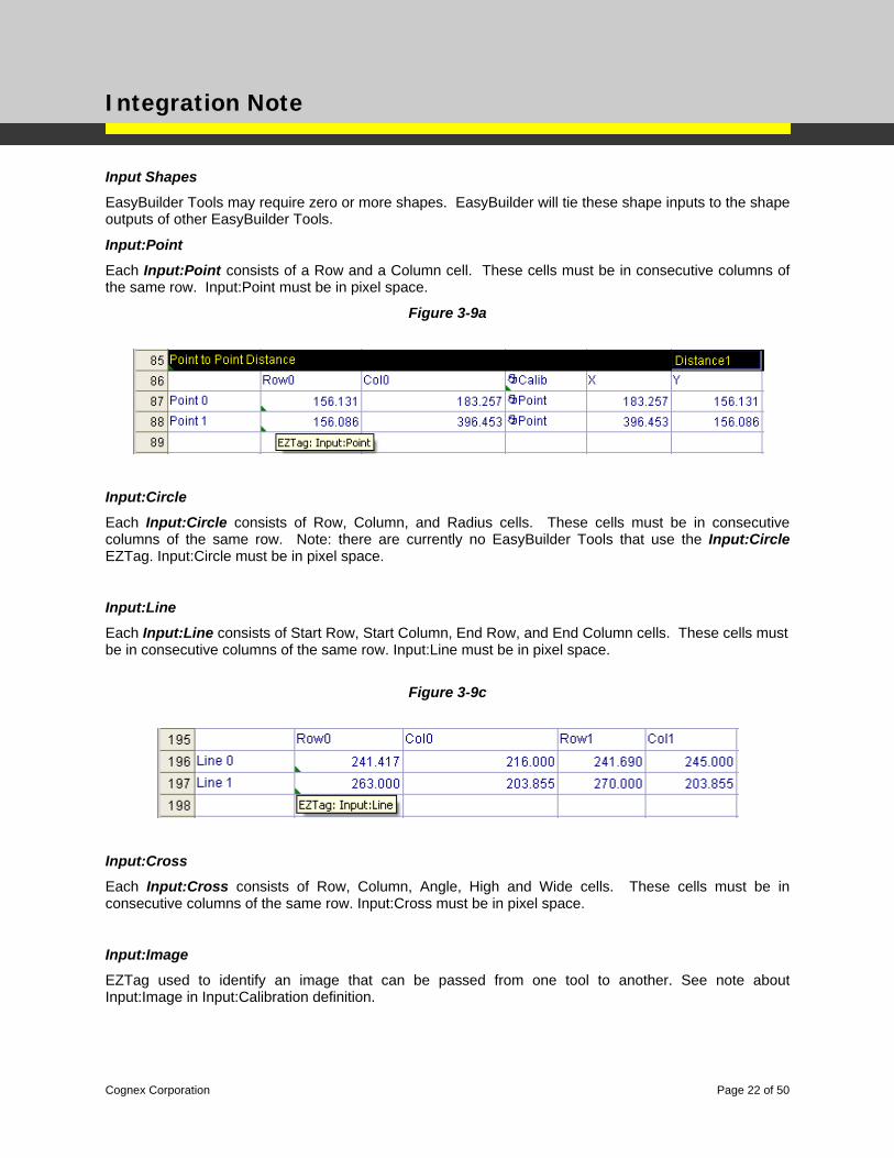
Input:Point
Each Input:Point consists of a Row and a Column cell. These cells must be in consecutive columns of the same row. Input:Point must be in pixel space.
Figure 3-9a
Input:Circle
Each Input:Circle consists of Row, Column, and Radius cells. These cells must be in consecutive columns of the same row. Note: there are currently no EasyBuilder Tools that use the Input:Circle EZTag. Input:Circle must be in pixel space.
Input:Line
Each Input:Line consists of Start Row, Start Column, End Row, and End Column cells. These cells must be in consecutive columns of the same row. Input:Line must be in pixel space.
Figure 3-9c
Input:Cross
Each Input:Cross consists of Row, Column, Angle, High and Wide cells. These cells must be in consecutive columns of the same row. Input:Cross must be in pixel space.
Input:Image
EZTag used to identify an image that can be passed from one tool to another. See note about Input:Image in Input:Calibration definition.
Cognex Corporation Page 22 of 50
Integration Note
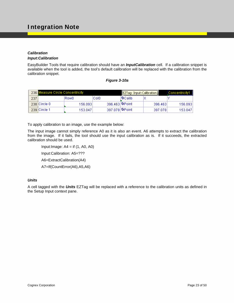
Calibration Input:Calibration
EasyBuilder Tools that require calibration should have an InputCalibration cell. If a calibration snippet is available when the tool is added, the tool’s default calibration will be replaced with the calibration from the calibration snippet.
Figure 3-10a
To apply calibration to an image, use the example below:
The input image cannot simply reference A0 as it is also an event. A6 attempts to extract the calibration from the image. If it fails, the tool should use the input calibration as is. If it succeeds, the extracted calibration should be used.
Input:Image: A4 = if (1, A0, A0)
Input:Calibration: A5=???
A6=ExtractCalibration(A4)
A7=If(CountError(A6),A5,A6)
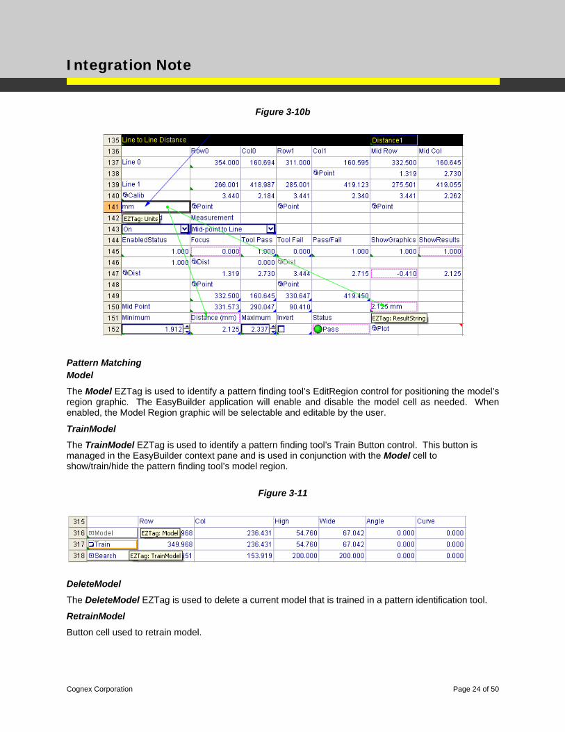
Units
A cell tagged with the Units EZTag will be replaced with a reference to the calibration units as defined in the Setup Input context pane.
Cognex Corporation Page 23 of 50
Integration Note
Figure 3-10b
Pattern Matching Model
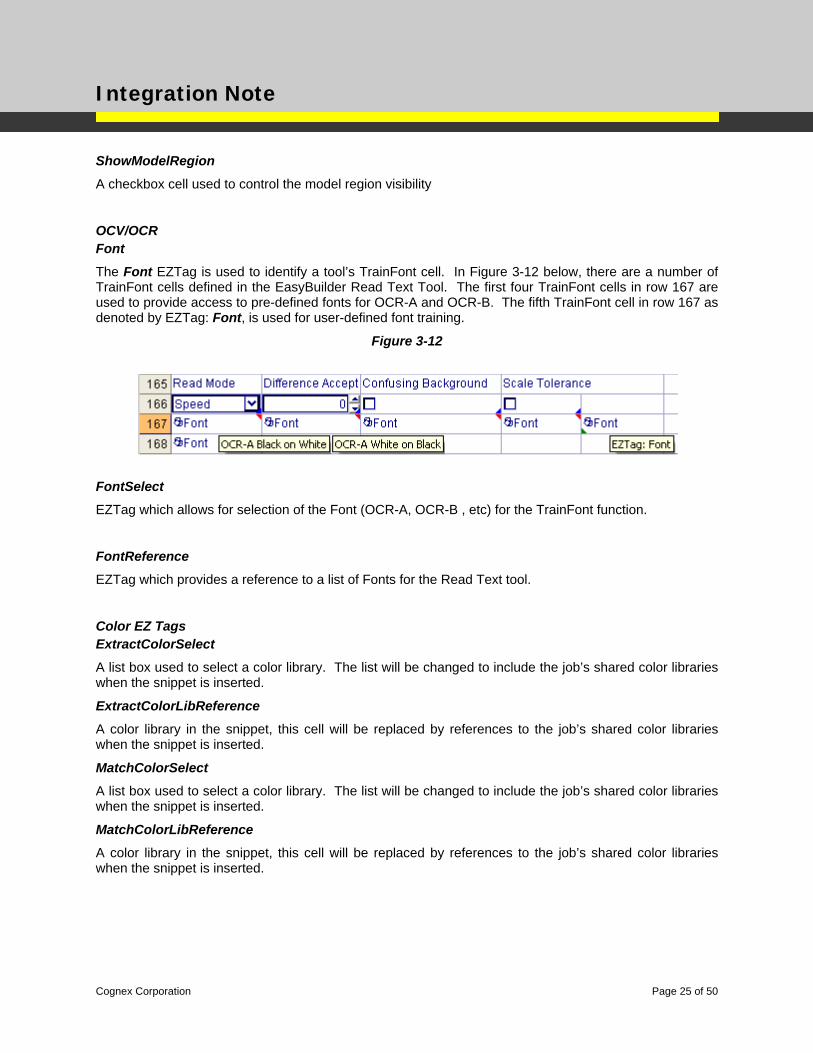
The Model EZTag is used to identify a pattern finding tool’s EditRegion control for positioning the model’s region graphic. The EasyBuilder application will enable and disable the model cell as needed. When enabled, the Model Region graphic will be selectable and editable by the user.
TrainModel
The TrainModel EZTag is used to identify a pattern finding tool’s Train Button control. This button is managed in the EasyBuilder context pane and is used in conjunction with the Model cell to show/train/hide the pattern finding tool’s model region.
Figure 3-11
DeleteModel
The DeleteModel EZTag is used to delete a current model that is trained in a pattern identification tool.
RetrainModel
Button cell used to retrain model.
Cognex Corporation Page 24 of 50
Integration Note
ShowModelRegion
A checkbox cell used to control the model region visibility
OCV/OCR Font
The Font EZTag is used to identify a tool’s TrainFont cell. In Figure 3-12 below, there are a number of TrainFont cells defined in the EasyBuilder Read Text Tool. The first four TrainFont cells in row 167 are used to provide access to pre-defined fonts for OCR-A and OCR-B. The fifth TrainFont cell in row 167 as denoted by EZTag: Font, is used for user-defined font training.
Figure 3-12
FontSelect
EZTag which allows for selection of the Font (OCR-A, OCR-B , etc) for the TrainFont function.
FontReference
EZTag which provides a reference to a list of Fonts for the Read Text tool.
Color EZ Tags ExtractColorSelect
A list box used to select a color library. The list will be changed to include the job’s shared color libraries when the snippet is inserted.
ExtractColorLibReference
A color library in the snippet, this cell will be replaced by references to the job’s shared color libraries when the snippet is inserted.
MatchColorSelect
A list box used to select a color library. The list will be changed to include the job’s shared color libraries when the snippet is inserted.
MatchColorLibReference
A color library in the snippet, this cell will be replaced by references to the job’s shared color libraries when the snippet is inserted.
Cognex Corporation Page 25 of 50
Integration Note
List
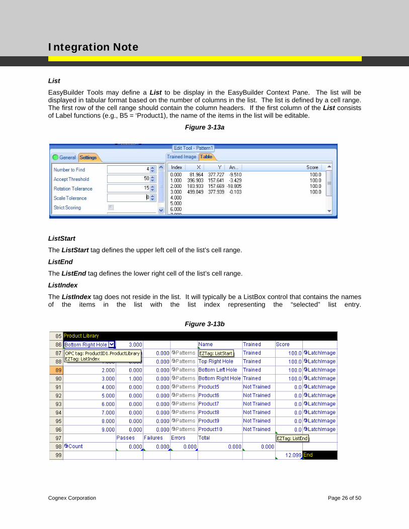
EasyBuilder Tools may define a List to be display in the EasyBuilder Context Pane. The list will be displayed in tabular format based on the number of columns in the list. The list is defined by a cell range. The first row of the cell range should contain the column headers. If the first column of the List consists of Label functions (e.g., B5 = ‘Product1), the name of the items in the list will be editable.
Figure 3-13a
ListStart
The ListStart tag defines the upper left cell of the list’s cell range.
ListEnd
The ListEnd tag defines the lower right cell of the list’s cell range.
ListIndex
The ListIndex tag does not reside in the list. It will typically be a ListBox control that contains the names of the items in the list with the list index representing the “selected” list entry.
Figure 3-13b
Cognex Corporation Page 26 of 50
Integration Note
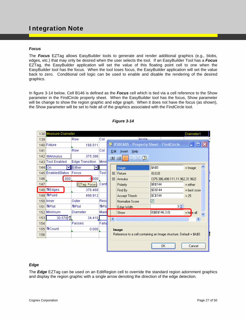
Focus
The Focus EZTag allows EasyBuilder tools to generate and render additional graphics (e.g., blobs, edges, etc.) that may only be desired when the user selects the tool. If an EasyBuilder Tool has a Focus EZTag, the EasyBuilder application will set the value of this floating point cell to one when the EasyBuilder tool has the focus. When the tool loses focus, the EasyBuilder application will set the value back to zero. Conditional cell logic can be used to enable and disable the rendering of the desired graphics.
In figure 3-14 below, Cell B146 is defined as the Focus cell which is tied via a cell reference to the Show parameter in the FindCircle property sheet. When the EasyBuilder tool has the focus, Show parameter will be change to show the region graphic and edge graph. When it does not have the focus (as shown), the Show parameter will be set to hide all of the graphics associated with the FindCircle tool.
Figure 3-14
Edge
The Edge EZTag can be used on an EditRegion cell to override the standard region adornment graphics and display the region graphic with a single arrow denoting the direction of the edge detection.
Cognex Corporation Page 27 of 50
Integration Note
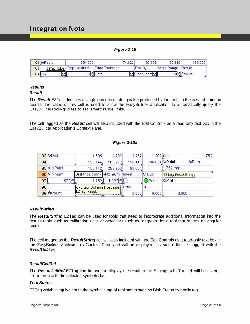
Figure 3-15
Results Result
The Result EZTag identifies a single numeric or string value produced by the tool. In the case of numeric results, the value of this cell is used to allow the EasyBuilder application to automatically query the EasyBuilderToolMgr class to set “smart” range limits.
The cell tagged as the Result cell will also included with the Edit Controls as a read-only text box in the EasyBuilder Application’s Context Pane.
Figure 3-16a
ResultString
The ResultString EZTag can be used for tools that need to incorporate additional information into the results table such as calibration units or other text such as “degrees” for a tool that returns an angular result.
The cell tagged as the ResultString cell will also included with the Edit Controls as a read-only text box in the EasyBuilder Application’s Context Pane and will be displayed instead of the cell tagged with the Result EZTag.
ResultCellRef
The ResultCellRef EZTag can be used to display the result in the Settings tab. The cell will be given a cell reference to the selected symbolic tag.
Tool Status
EZTag which is equivalent to the symbolic tag of tool.status such as Blob.Status symbolic tag.
Cognex Corporation Page 28 of 50
Integration Note
Show
The Show EZTag will cause the tagged cell to be displayed as a read-only value in the Settings Tab of the Context Pane. The cell value will also be exposed to the EasyBuilder communication subsystems. Note: None of the current set of EasyBuilder Tools uses the Show EZTag.
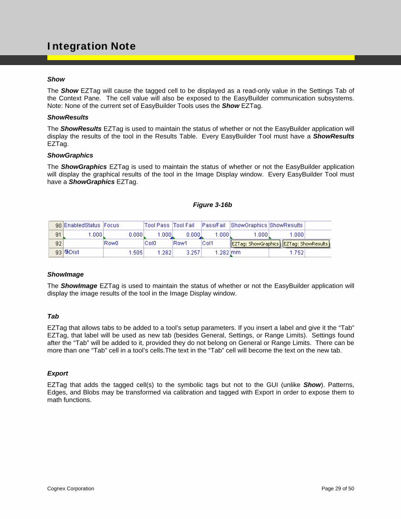
ShowResults
The ShowResults EZTag is used to maintain the status of whether or not the EasyBuilder application will display the results of the tool in the Results Table. Every EasyBuilder Tool must have a ShowResults EZTag.
ShowGraphics
The ShowGraphics EZTag is used to maintain the status of whether or not the EasyBuilder application will display the graphical results of the tool in the Image Display window. Every EasyBuilder Tool must have a ShowGraphics EZTag.
Figure 3-16b
ShowImage
The ShowImage EZTag is used to maintain the status of whether or not the EasyBuilder application will display the image results of the tool in the Image Display window.
Tab
EZTag that allows tabs to be added to a tool’s setup parameters. If you insert a label and give it the “Tab” EZTag, that label will be used as new tab (besides General, Settings, or Range Limits). Settings found after the “Tab” will be added to it, provided they do not belong on General or Range Limits. There can be more than one “Tab” cell in a tool’s cells.The text in the “Tab” cell will become the text on the new tab.
Export
EZTag that adds the tagged cell(s) to the symbolic tags but not to the GUI (unlike Show). Patterns, Edges, and Blobs may be transformed via calibration and tagged with Export in order to expose them to math functions.
Cognex Corporation Page 29 of 50
Integration Note
Supplemental Graphics
Supplemental graphics are often provided by the underlying In-Sight vision tools to aid the user when setting up a tool. Within the spreadsheet environment, these graphics are generally rendered at as overlay graphics in the Image Display control or at the bottom of Image Display Control while the property sheet for the vision tool is open. In the EasyBuilder GUI, these supplemental graphics will be in the Context Pane for the Find Part and Inspect Part application steps while editing the tool and when the tool has the focus. Note: Most supplemental graphics are drawn without requiring EZTags.
Image Graphics
The following supplemental graphics will be drawn in the EasyBuilder image display window.
Edges
Edge graphics will be drawn on the image.
Blobs
Blob perimeter graphics will be drawn on the image.
Context Pane Graphics
The following supplemental graphics will be drawn in the EasyBuilder context pane.
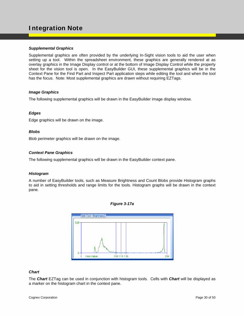
Histogram
A number of EasyBuilder tools, such as Measure Brightness and Count Blobs provide Histogram graphs to aid in setting thresholds and range limits for the tools. Histogram graphs will be drawn in the context pane.
Figure 3-17a
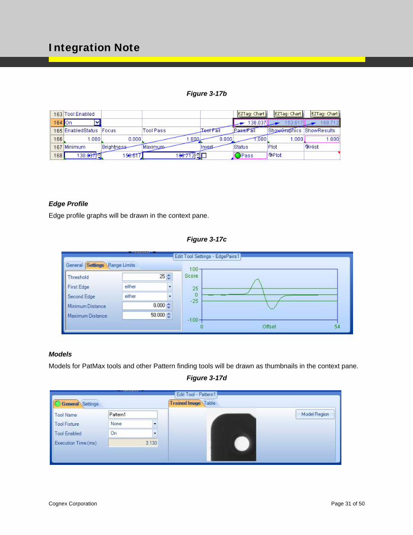
Chart
The Chart EZTag can be used in conjunction with histogram tools. Cells with Chart will be displayed as a marker on the histogram chart in the context pane.
Cognex Corporation Page 30 of 50
Integration Note
Figure 3-17b
Edge Profile
Edge profile graphs will be drawn in the context pane.
Figure 3-17c
Models
Models for PatMax tools and other Pattern finding tools will be drawn as thumbnails in the context pane.
Figure 3-17d
Cognex Corporation Page 31 of 50
Integration Note
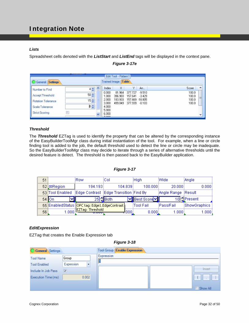
Lists
Spreadsheet cells denoted with the ListStart and ListEnd tags will be displayed in the context pane.
Figure 3-17e
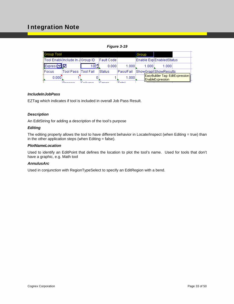
Threshold
The Threshold EZTag is used to identify the property that can be altered by the corresponding instance of the EasyBuilderToolMgr class during initial instantiation of the tool. For example, when a line or circle finding tool is added to the job, the default threshold used to detect the line or circle may be inadequate. So the EasyBuilderToolMgr class may decide to iterate through a series of alternative thresholds until the desired feature is detect. The threshold is then passed back to the EasyBuilder application.
Figure 3-17
EditExpression
EZTag that creates the Enable Expression tab
Figure 3-18
Cognex Corporation Page 32 of 50
Integration Note
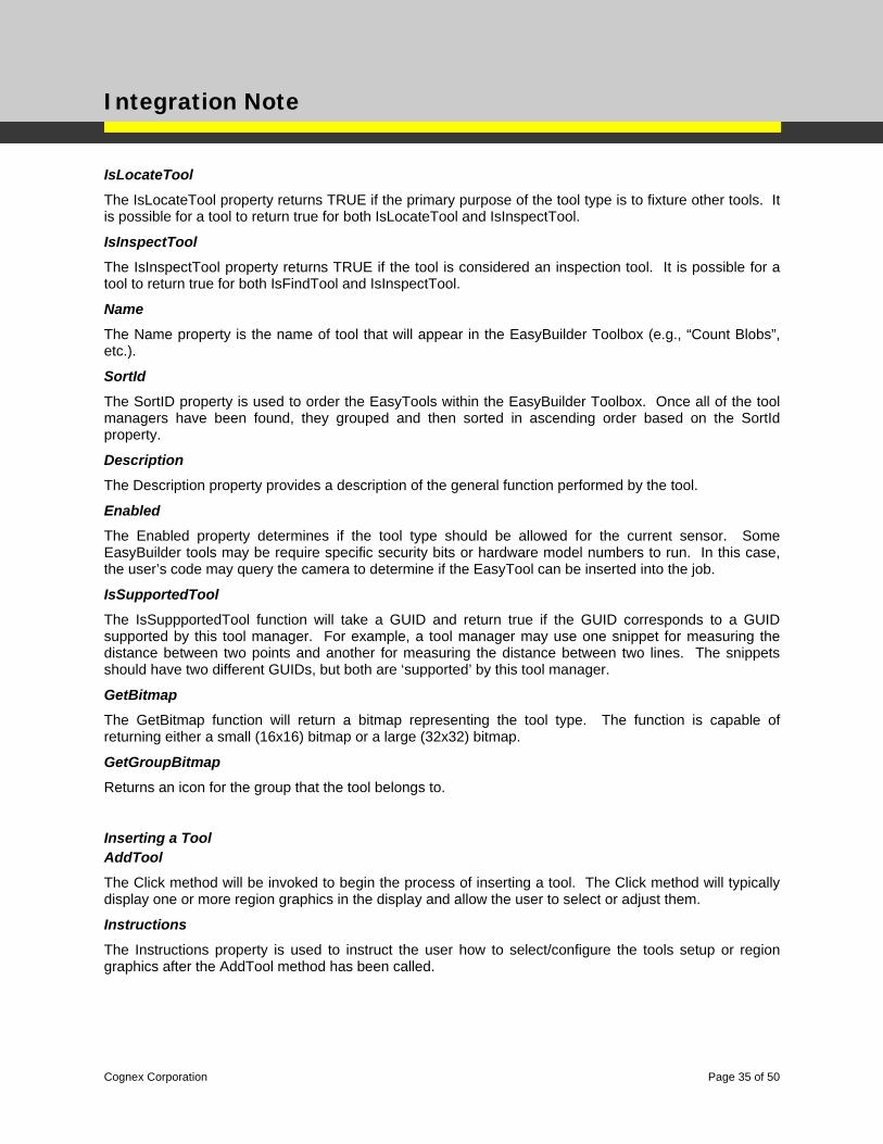
Figure 3-19
IncludeInJobPass
EZTag which indicates if tool is included in overall Job Pass Result.
Description
An EditString for adding a description of the tool’s purpose
Editing
The editing property allows the tool to have different behavior in Locate/Inspect (when Editing = true) than in the other application steps (when Editing = false).
PlotNameLocation
Used to identify an EditPoint that defines the location to plot the tool’s name. Used for tools that don’t have a graphic, e.g. Math tool
AnnulusArc
Used in conjunction with RegionTypeSelect to specify an EditRegion with a bend.
Cognex Corporation Page 33 of 50

Integration Note
Publishing Spreadsheet Data to the EasyBuilder Application There may be instances where spreadsheet logic is needed to create additional data to solve an application, but there is not a need for a corresponding EasyBuilder Tool. In these instances, several Snippet templates exist in the EasyEdit snippet library to publish spreadsheet data to the EasyBuilder application environment for display in the Result Table and for exposure to the Communication subsystem.
To use these snippets, you need to go into the Spreadsheet view and manually add (e.g. drag-and-drop) the snippets into the EasyBuilder job and then fill in the template to meet your needs. These template snippets use a GUID recognized by the EasyBuilder application so they will be “wired” into the corresponding EasyBuilder spreadsheet structures when you return to the EasyBuilder view.
EasyBuilder In-Sight SDK Objects
The In-Sight SDK includes additional class libraries to facilitate building and deploying EasyBuilder Tools.
Populating the EasyBuilder Tool Box
Using reflection, the EasyBuilder application will search for DLLs in the same directory as “In-Sight Explorer.exe” program file looking for classes that inherit from EasyBuilderToolMgr.
Class Library
There are three primary classes for creating an EasyBuilder Tool. The primary class is the EasyBuilderToolMgr class. This class provides the public interface for creating a DLL to expose the EasyBuilder tool to the EasyBuilder application. There is another class called MeasureRegion that inherits from the EasyBuilderToolMgr class and automatically implements default behavior for a number of the class members.
The EasyBuilderSystem class provides a number of functions that provide the application developer a means interact with the EasyBuilder application for system level functions, and gain access to the cvsInSight & cvsInSightDisplay classes which are part of the In-Sight SDK
The EasyBuilderTool class provides a number of functions that provide the application developer with a means to query the EasyBuilderApplication for tool level functions, principally associated with EasyTags.
EasyBuilderToolMgr Class
The EasyBuilder Tool Manager is a .NET class used to populate the EasyBuilder “toolbox” and insert new instances Easy Tools into the EasyBuilder “job”.
Group
The Group property is a string used to categorize the different tool types (e.g., “Geometry”, etc.).
Cognex Corporation Page 34 of 50
Integration Note
IsLocateTool
The IsLocateTool property returns TRUE if the primary purpose of the tool type is to fixture other tools. It is possible for a tool to return true for both IsLocateTool and IsInspectTool.
IsInspectTool
The IsInspectTool property returns TRUE if the tool is considered an inspection tool. It is possible for a tool to return true for both IsFindTool and IsInspectTool.
Name
The Name property is the name of tool that will appear in the EasyBuilder Toolbox (e.g., “Count Blobs”, etc.).
SortId
The SortID property is used to order the EasyTools within the EasyBuilder Toolbox. Once all of the tool managers have been found, they grouped and then sorted in ascending order based on the SortId property.
Description
The Description property provides a description of the general function performed by the tool.
Enabled
The Enabled property determines if the tool type should be allowed for the current sensor. Some EasyBuilder tools may be require specific security bits or hardware model numbers to run. In this case, the user’s code may query the camera to determine if the EasyTool can be inserted into the job.
IsSupportedTool
The IsSuppportedTool function will take a GUID and return true if the GUID corresponds to a GUID supported by this tool manager. For example, a tool manager may use one snippet for measuring the distance between two points and another for measuring the distance between two lines. The snippets should have two different GUIDs, but both are ‘supported’ by this tool manager.
GetBitmap
The GetBitmap function will return a bitmap representing the tool type. The function is capable of returning either a small (16x16) bitmap or a large (32x32) bitmap.
GetGroupBitmap
Returns an icon for the group that the tool belongs to.
Inserting a Tool AddTool
The Click method will be invoked to begin the process of inserting a tool. The Click method will typically display one or more region graphics in the display and allow the user to select or adjust them.
Instructions
The Instructions property is used to instruct the user how to select/configure the tools setup or region graphics after the AddTool method has been called.
Cognex Corporation Page 35 of 50
Integration Note
ShowInstructions
Should return true if the instructions should be shown. For example, the math and logic tools have no pre-add setup, so they would return false.
ShowOKButton
The Show OK Button property determines if the OK button should be shown in the EasyBuilder user interface. Depending on the function of the EasyTool, the user may complete the process of adding the tool by simply selecting a graphical object in the image display, or the user may be required to click on OK Button.
AcceptChanges Event
For tools that do not show the OK button, the AcceptChanges event must be fired to cause the system to complete the initial configuration of the tool. For example, the standard Measure Distance tool will fire the AcceptChanges event as soon as the second graphic has been selected.
EditComplete Event
The tool will fire the EditComplete event after a new instance of the tool has been added.
InstructionsChanged Event
This is specifically for tools that might be ‘multi-state’. It allows the tool manager to change the instructions. For example, in the point to point dimension tool, the user first selects two points and THEN selects a line. The tool manager can change the instructions for each state.
Visible
Returns true if the tool type should be shown in the tree.
List<Control> GetEditControls(EasyBuilderTool tool)
Returns a list of controls for editing the selected tool. The controls will end up as tabs along with the supplemental graphics.
SupportsImageInput
Returns true if the tool has an image input.
OnSourceImageChanged
Call when the source image has been changed, while the tool is being added but before the snippet has been added.
Cognex Corporation Page 36 of 50
Integration Note
EasyBuilderSystem Class
The EasyBuilderSystem class provides a number of services that can be used by EasyTools. Access to the EasyBuilderSystem class is provided via a member variable of the EasyBuilderToolManager class. Below is a list of some of the useful functions.
EZSystem.AddUndo
Instructs EasyBuilder software to include the Add of the EasyTool into the undo buffer.
EZSystem.Display
Provide a handle to the cvsInSightDisplay object.
EZSystem.EditBounds
Provide height and width values for the current image size.
EZSystem.FindCircles
Instructs EasyBuilder software to run the FindCircle smart-feature detector and returns a list of candidate circles.
EZSystem.FindLines
Instructs EasyBuilder software to run the FindLine smart-feature detector and returns a list of candidate line segments.
EZSystem.InsertFindCircleSnippet
Instructs EasyBuilder software to insert a the standard FindCircle snippet into the spreadsheet, allowing your EasyTool to leverage existing EasyTools
EZSystem.InsertFindLineSnippet
Instructs EasyBuilder software to insert a the standard FindLine snippet into the spreadsheet, allowing your EasyLine to leverage existing EasyTools
EZSystem.InSight
Provide a handle to the cvsInSight object.
EZSystem.UpdateResults
Instructs EasyBuilder software to re-execute the spreadsheet in order to update the current results. This is needed when setting smart limits for your EasyTool
Cognex Corporation Page 37 of 50
Integration Note
EasyBuilderTool Class
The EasyBuilderTool class provides a number of services that can be used by EasyTools. Access to the EasyBuilderTool class is provided via a member variable of the EasyBuilderToolManager class.
EZSystem.Tools[].FindTaggedLocation
Provides a way to locate cells containing EasyTags in order for your EasyTool to provide smart-limits or smart-settings back to the snippet after it has been added to the spreadsheet.
EasyBuilderProtocol Class
Protocols are also extensible based on the classes EasyBuilderProtocolMgr and EasyBuilderProtocol. The snippets are built similarly to the tool snippets, i.e. with the same GUIDs to identify the snippet.
EasyBuilderProtocolMgr.BrowseName
A string that identifies the protocol. The string does not get translated.
EasyBuilderProtocolMgr.DisplayName
The displayed name of the protocol. The string does get translated.
EasyBuilderProtocolMgr.Enabled
Returns true if the protocol is enabled for the current sensor.
EasyBuilderProtocolMgr.IsSupportedProtocol
Returns true if the protocol is supported by the manager.
EasyBuilderProtocolMgr.GetSnippet
Gets the snippet name for the protocol.
EasyBuilderProtocolMgr.CreateProtocol
Called by EZB to create the EasyBuilderProtocol-based class after the snippet has been inserted.
EasyBuilderProtocol.Initialize
Called to initialize the protocol after the snippet has been inserted.
EasyBuilderProtocol.BrowseName
A string that identifies the protocol. The string does not get translated.
Cognex Corporation Page 38 of 50
Integration Note
EasyBuilderProtocol.DisplayName
The displayed name of the protocol. The string does get translated.
EasyBuilderProtocol.GetEditControls
Returns a list of controls for editing the protocol.
EasyBuilderProtocol.UpdateSymbolicTags
Called to update the symbolic tags that may belong to the protocol.
EasyBuilderProtocol.Save
Called to save the current settings of the protocol.
EasyBuilderProtocol.Restore
Called to restore the settings of the previous protocol.
EasyBuilderDevice
Used to populate the communication device list boxes.
EasyBuilderDevice.DeviceType
PLC, Robot, etc.
EasyBuilderDevice.Manufacturer
ABB, Mitsubishi, etc.
EasyBuilderDevice.ManufacturerBrowseName
ABB, Mitsubishi, etc., but not translated.
EasyBuilderDevice.IsSupportedProtocol
Returns true if the protocol is supported by the device.
EasyBuilderCalibration Class
Calibration is also extensible based on the following classes: EasyBuilderCalibrationMgr and
EasyBuilderCalibration
Cognex Corporation Page 39 of 50
Integration Note
EasyBuilderCalibrationMgr.BrowseName
A string that identifies calibration. The string does not get translated.
EasyBuilderCalibrationMgr.DisplayName
The displayed name of calibration. The string does get translated.
EasyBuilderCalibrationMgr.Enabled
Returns true if calibration is enabled for the current sensor.
EasyBuilderCalibrationMgr.SortId EasyBuilderCalibrationMgr.IsSupportedCalibration EasyBuilderCalibrationMgr.GetSnippet EasyBuilderCalibrationMgr.CreateCalibration EasyBuilderCalibration.BrowseName EasyBuilderCalibration.DisplayName EasyBuilderCalibration.GetEditControls
Returns a list of controls for configuring calibration. NOTE: currently, only one control is allowed.
EasyBuilderCalibration.OutputCalibrationLocation
The base class will look for an EZTag of “Output:Calibration”
EasyBuilderCalibration.OutputUnitsStringLocation
The base class will look for an EZTag of “Output:UnitString”
Cognex Corporation Page 40 of 50
Integration Note
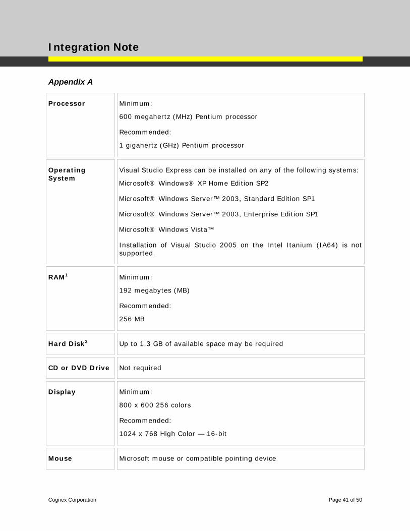
Appendix A
Processor Minimum:
600 megahertz (MHz) Pentium processor
Recommended:
1 gigahertz (GHz) Pentium processor
Operating System
Visual Studio Express can be installed on any of the following systems:
Microsoft® Windows® XP Home Edition SP2
Microsoft® Windows Server™ 2003, Standard Edition SP1
Microsoft® Windows Server™ 2003, Enterprise Edition SP1
Microsoft® Windows Vista™
Installation of Visual Studio 2005 on the Intel Itanium (IA64) is not supported.
RAM1 Minimum:
192 megabytes (MB)
Recommended:
256 MB
Hard Disk2 Up to 1.3 GB of available space may be required
CD or DVD Drive Not required
Display Minimum:
800 x 600 256 colors
Recommended:
1024 x 768 High Color — 16-bit
Mouse Microsoft mouse or compatible pointing device
Cognex Corporation Page 41 of 50

Integration Note
Appendix B: ToolBuilder Deployment Example – VB.NET In this example, a custom tool created from a snippet will be published for view in the EasyBuilder Toolbox.
Prerequisites:
Spreadsheet code was created following the snippet structure (ref. EasyBuilder Tool Development section of this document). The snippet of code uses the blob tool to detect “flaws” in a given region. The appropriate EZTags and graphics have been added to the code(ref. Spreadsheet Syntax and EZTag Specification section of this document). The spreadsheet code was then exported as a snippet with the name: ToolBuilderDeploymentEx.cxd
This example will detail how to create a dll in VB.NET to publish the snippet and make the tool visible in the EasyBuilder Toolbox. Note: Microsoft Visual Studio Express 2005 or 2008 can be used. In this example, 2008 is referenced.
Step 1: Create a New Class Library o Launch Microsoft Visual Studio 2008 o Choose: File New Project Class Library o Name = MyEasyTool1 o In the Solution Explorer, rename the .vb file to MyEasyTool1.vb
o Add the In-Sight DLL references
Note: You must use the SDK version that matches the ISE version you will be using. For example: Use SDK 4.5 dlls for building tools and running tools in ISE 4.5.
Choose the menu Project Add Reference Browse…
Program Files\Common Files\Cognex\InSight\<4.1.xxxx.x>\Cognex.InSight.Controls.Display.dll
Program Files\Common Files\Cognex\InSight\<4.1.xxxx.x >\Cognex.InSight.dll Note: You must use the 4.1.xxxx.x DLLs or later
Step 2: Create VB.Net Code o 2.1 – Add the EasyBuilder Namespace and create the class
Imports Cognex.InSight.Controls.Display.EZBuilder
Imports Cognex.InSight
Inherit the base class by adding Inherits MeasureRegion to the class:
Public Class MyEasyTool1
Inherits MeasureRegion ‘for tools using a standard input region
Cognex Corporation Page 42 of 50
Integration Note
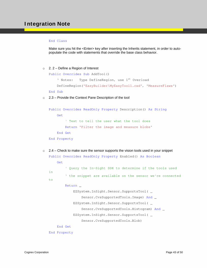
End Class Make sure you hit the <Enter> key after inserting the Inherits statement, in order to auto-populate the code with statements that override the base class behavior.
o 2. 2 – Define a Region of Interest
Public Overrides Sub AddTool()
‘ Notes: Type DefineRegion, use 1st Overload
DefineRegion("EasyBuilder\MyEasyTool1.cxd", "MeasureFlaws")
End Sub
o 2.3 – Provide the Context Pane Description of the tool
Public Overrides ReadOnly Property Description() As String
Get
‘ Text to tell the user what the tool does
Return "Filter the image and measure blobs"
End Get
End Property
o 2.4 – Check to make sure the sensor supports the vision tools used in your snippet
Public Overrides ReadOnly Property Enabled() As Boolean
Get
‘ Query the In-Sight SDK to determine if the tools used in ‘ the snippet are available on the sensor we're connected to
Return _
EZSystem.InSight.Sensor.SupportsTool( _
Sensor.CvsSupportedTools.Image) And _
EZSystem.InSight.Sensor.SupportsTool( _
Sensor.CvsSupportedTools.Histogram) And _
EZSystem.InSight.Sensor.SupportsTool( _
Sensor.CvsSupportedTools.Blob)
End Get
End Property
Cognex Corporation Page 43 of 50
Integration Note
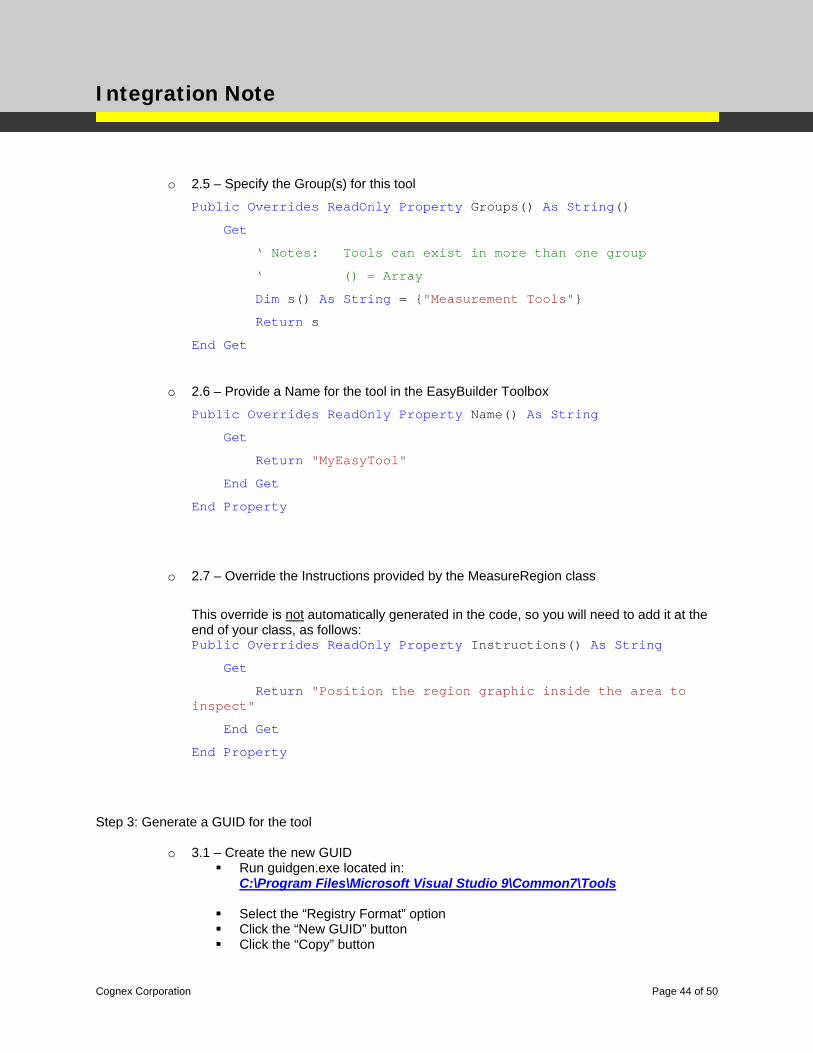
o 2.5 – Specify the Group(s) for this tool
Public Overrides ReadOnly Property Groups() As String()
Get
‘ Notes: Tools can exist in more than one group
‘ () = Array
Dim s() As String = {"Measurement Tools"}
Return s
End Get
o 2.6 – Provide a Name for the tool in the EasyBuilder Toolbox
Public Overrides ReadOnly Property Name() As String
Get
Return "MyEasyTool"
End Get
End Property
o 2.7 – Override the Instructions provided by the MeasureRegion class
This override is not automatically generated in the code, so you will need to add it at the end of your class, as follows: Public Overrides ReadOnly Property Instructions() As String
Get
Return "Position the region graphic inside the area to inspect"
End Get
End Property
Step 3: Generate a GUID for the tool
o 3.1 – Create the new GUID Run guidgen.exe located in:
C:\Program Files\Microsoft Visual Studio 9\Common7\Tools
Select the “Registry Format” option Click the “New GUID” button Click the “Copy” button
Cognex Corporation Page 44 of 50
Integration Note
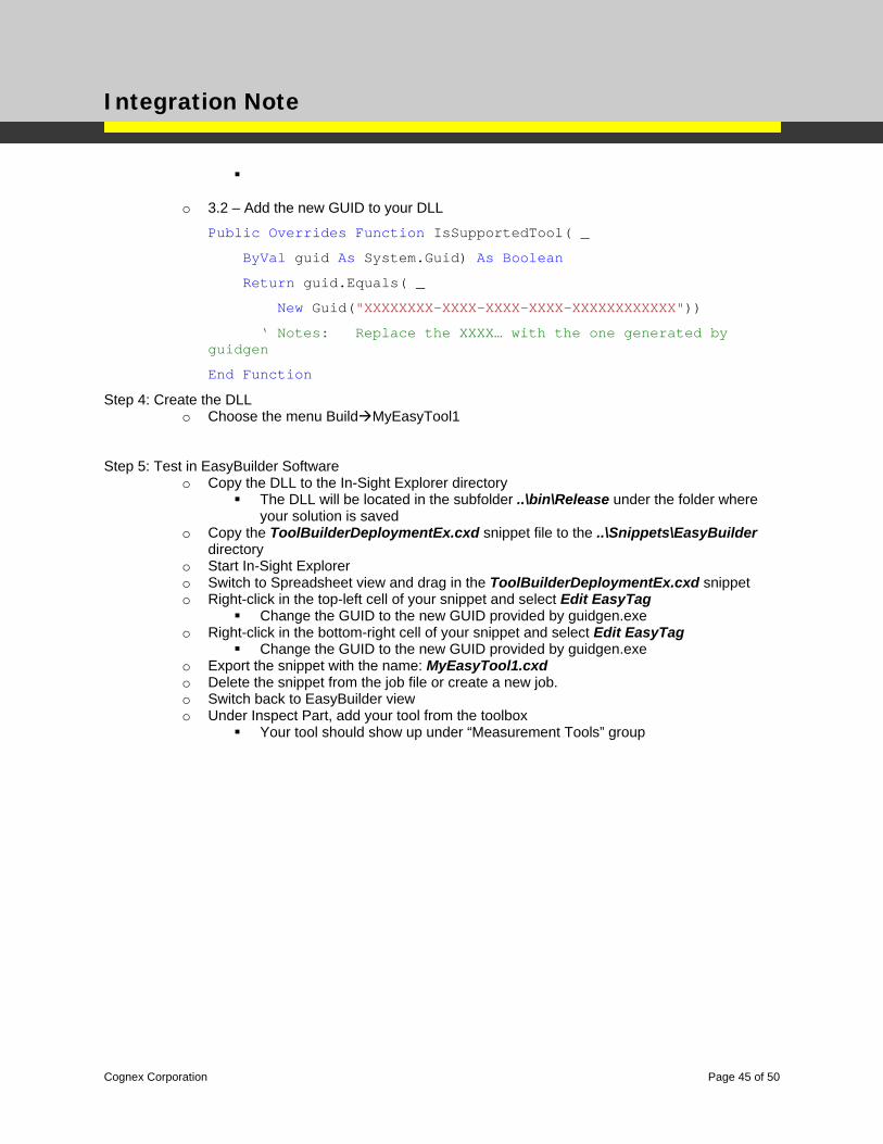
o 3.2 – Add the new GUID to your DLL
Public Overrides Function IsSupportedTool( _
ByVal guid As System.Guid) As Boolean
Return guid.Equals( _
New Guid("XXXXXXXX-XXXX-XXXX-XXXX-XXXXXXXXXXXX"))
‘ Notes: Replace the XXXX… with the one generated by guidgen
End Function
Step 4: Create the DLL o Choose the menu Build MyEasyTool1
Step 5: Test in EasyBuilder Software o Copy the DLL to the In-Sight Explorer directory
The DLL will be located in the subfolder ..\bin\Release under the folder where your solution is saved
o Copy the ToolBuilderDeploymentEx.cxd snippet file to the ..\Snippets\EasyBuilder directory
o Start In-Sight Explorer o Switch to Spreadsheet view and drag in the ToolBuilderDeploymentEx.cxd snippet o Right-click in the top-left cell of your snippet and select Edit EasyTag
Change the GUID to the new GUID provided by guidgen.exe o Right-click in the bottom-right cell of your snippet and select Edit EasyTag
Change the GUID to the new GUID provided by guidgen.exe o Export the snippet with the name: MyEasyTool1.cxd o Delete the snippet from the job file or create a new job. o Switch back to EasyBuilder view o Under Inspect Part, add your tool from the toolbox
Your tool should show up under “Measurement Tools” group
Cognex Corporation Page 45 of 50

Integration Note
Appendix C: ToolBuilder Deployment Example – C# In this example, a custom tool created from a snippet will be published for view in the EasyBuilder Toolbox.
Prerequisites:
Spreadsheet code was created following the snippet structure (ref. EasyBuilder Tool Development section of this document). The snippet of code uses the blob tool to detect “flaws” in a given region. The appropriate EZTags and graphics have been added to the code(ref. Spreadsheet Syntax and EZTag Specification section of this document). The spreadsheet code was then exported as a snippet with the name: ToolBuilderDeploymentEx.cxd
This example will detail how to create a dll in C# to publish the snippet and make the tool visible in the EasyBuilder Toolbox. Note: Microsoft Visual Studio Express 2005 or 2008 can be used. In this example, 2008 is referenced.
Step 1: Create a New Class Library
o Launch Microsoft Visual Studio 2008 o Choose: File New Project Class Library o Name = MyEasyTool1 o In the Solution Explorer, rename the .cs file to MyEasyTool1.cs
o Add the In-Sight DLL references
Note: You must use the SDK version that matches the ISE version you will be using. For example: Use SDK 4.5 dlls for building tools and running tools in ISE 4.5.
Choose the menu Project Add Reference Browse…
Program Files\Common Files\Cognex\InSight\<4.1.xxxx.x>\Cognex.InSight.Controls.Display.dll
Program Files\Common Files\Cognex\InSight\<4.1.xxxx.x >\Cognex.InSight.dll Note: You must use the 4.1.xxxx.x DLLs or later
Step 2: Create C# Code o 2.1 – Add the EasyBuilder Namespace and create the class
// Case sensitive
using Cognex.InSight.Controls.Display.EZBuilder;
using Cognex.InSight;
Inherit the base class by modifying the section
Cognex Corporation Page 46 of 50
Integration Note
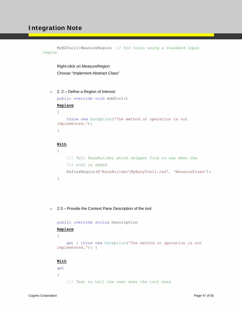
MyEZTool1:MeasureRegion // for tools using a standard input region
Right-click on MeasureRegion
Choose “Implement Abstract Class”
o 2. 2 – Define a Region of Interest
public override void AddTool()
Replace
{
throw new Exception("The method or operation is not implemented.");
}
With
{
/// Tell EasyBuilder which snippet file to use when the
/// tool is added
DefineRegion(@"EasyBuilder\MyEasyTool1.cxd", "MeasureFlaws");
}
o 2.3 – Provide the Context Pane Description of the tool
public override string Description
Replace
{
get { throw new Exception("The method or operation is not implemented."); }
With
get
{
/// Text to tell the user what the tool does
Cognex Corporation Page 47 of 50
Integration Note
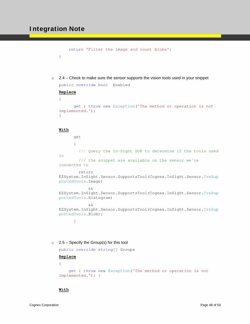
return "Filter the image and count blobs";
}
o 2.4 – Check to make sure the sensor supports the vision tools used in your snippet
public override bool Enabled
Replace
{
get { throw new Exception("The method or operation is not implemented."); }
With
get
{
/// Query the In-Sight SDK to determine if the tools used in /// the snippet are available on the sensor we're connected to
return EZSystem.InSight.Sensor.SupportsTool(Cognex.InSight.Sensor.CvsSupportedTools.Image)
&& EZSystem.InSight.Sensor.SupportsTool(Cognex.InSight.Sensor.CvsSupportedTools.Histogram)
&& EZSystem.InSight.Sensor.SupportsTool(Cognex.InSight.Sensor.CvsSupportedTools.Blob);
}
o 2.5 – Specify the Group(s) for this tool
public override string[] Groups
Replace
{
get { throw new Exception("The method or operation is not implemented."); }
With
Cognex Corporation Page 48 of 50
Integration Note
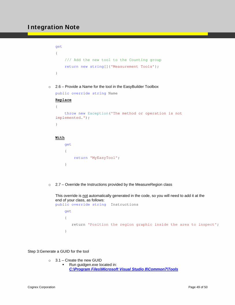
get
{
/// Add the new tool to the Counting group
return new string[]{"Measurement Tools"};
}
o 2.6 – Provide a Name for the tool in the EasyBuilder Toolbox
public override string Name
Replace
{
throw new Exception("The method or operation is not implemented.");
}
With
get
{
return "MyEasyTool";
}
o 2.7 – Override the Instructions provided by the MeasureRegion class
This override is not automatically generated in the code, so you will need to add it at the end of your class, as follows: public override string Instructions
get
{
return "Position the region graphic inside the area to inspect";
}
Step 3:Generate a GUID for the tool
o 3.1 – Create the new GUID Run guidgen.exe located in:
C:\Program Files\Microsoft Visual Studio 8\Common7\Tools
Cognex Corporation Page 49 of 50
Integration Note
Cognex Corporation Page 50 of 50
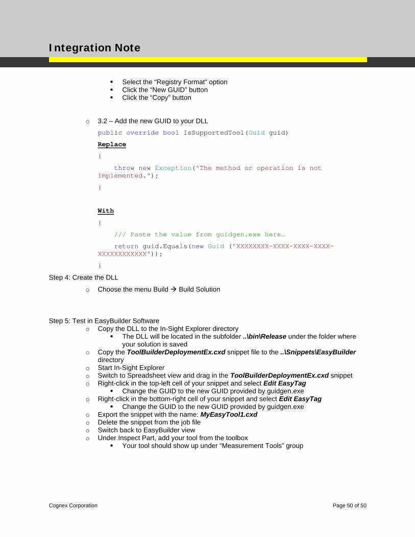
Select the “Registry Format” option Click the “New GUID” button Click the “Copy” button
o 3.2 – Add the new GUID to your DLL
public override bool IsSupportedTool(Guid guid)
Replace
{
throw new Exception("The method or operation is not implemented.");
}
With
{
/// Paste the value from guidgen.exe here…
return guid.Equals(new Guid ("XXXXXXXX-XXXX-XXXX-XXXX-XXXXXXXXXXXX"));
}
Step 4: Create the DLL
o Choose the menu Build Build Solution
Step 5: Test in EasyBuilder Software o Copy the DLL to the In-Sight Explorer directory
The DLL will be located in the subfolder ..\bin\Release under the folder where your solution is saved
o Copy the ToolBuilderDeploymentEx.cxd snippet file to the ..\Snippets\EasyBuilder directory
o Start In-Sight Explorer o Switch to Spreadsheet view and drag in the ToolBuilderDeploymentEx.cxd snippet o Right-click in the top-left cell of your snippet and select Edit EasyTag
Change the GUID to the new GUID provided by guidgen.exe o Right-click in the bottom-right cell of your snippet and select Edit EasyTag
Change the GUID to the new GUID provided by guidgen.exe o Export the snippet with the name: MyEasyTool1.cxd o Delete the snippet from the job file o Switch back to EasyBuilder view o Under Inspect Part, add your tool from the toolbox
Your tool should show up under “Measurement Tools” group