tool removed during cycle fault #2 conditions for setting tool cocked prox switch goes open during...
DESCRIPTION
Fast Run Rotation Limit Exceeded Fault #3 Conditions for Setting The nut runner is set up to stop running if it exceeds the maximum number for revolutions allowed. This fault is set if the nut runner reaches this maximum number of revolutions without achieving the pretension target. Fault Setting Sequence If the PLC receives a cycle complete OK from the nut runner controller during the Fast Run process then this indicates the nut runner ran the maximum number of revolutions allowed before the target tension was achieved. Under normal conditions the target tension will be reached before the nut runner reaches the max number of revolutions. Once the target tension is achieved the PLC will turn off the run command. Under normal conditions the run command is turned off before the nut runner reached the max allowed revolutions so the cycle complete OK is not sent. Page 3 Continued next pageTRANSCRIPT


Tool Removed During CycleFault #2
Conditions for SettingTool cocked prox switch goes open during cycle AND force on load
cell drops below 5 lbs.
Active in Slow Forward and Reverse Revolution processes.
TroubleshootingInstall tool on job and restart. It may be necessary to back off nut
before tool can be reinstalled.
If tool is releasing the nut without the release ring being pulled then see Cocking System Troubleshooting & Repair
Causes for SettingRelease ring pulled prior to cycle being complete
Locking mechanism in tool is releasing inadvertently.
Page 2

Fast Run Rotation Limit Exceeded Fault #3
Conditions for SettingThe nut runner is set up to stop running if it exceeds the maximum number for revolutions allowed. This fault is set if the nut runner reaches this maximum number of revolutions without achieving the pretension target.
Fault Setting Sequence
If the PLC receives a cycle complete OK from the nut runner controller during the Fast Run process then this indicates the nut runner ran the maximum number of revolutions allowed before the target tension was achieved. Under normal conditions the target tension will be reached before the nut runner reaches the max number of revolutions. Once the target tension is achieved the PLC will turn off the run command. Under normal conditions the run command is turned off before the nut runner reached the max allowed revolutions so the cycle complete OK is not sent.
Page 3Continued next page
Fast Run Rotation Limit Exceeded Fault #3
Troubleshooting Pg 1
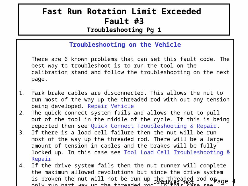
Troubleshooting on the Vehicle
There are 6 known problems that can set this fault code. The best way to troubleshoot is to run the tool on the calibration stand and follow the troubleshooting on the next page.
1. Park brake cables are disconnected. This allows the nut to run most of the way up the threaded rod with out any tension being developed. Repair Vehicle
2. The quick connect system fails and allows the nut to pull out of the tool in the middle of the cycle. If this is being reported then see Quick Connect Troubleshooting & Repair.
3. If there is a load cell failure then the nut will be run most of the way up the threaded rod. There will be a large amount of tension in cables and the brakes will be fully locked up. In this case see Tool Load Cell Troubleshooting & Repair
4. If the drive system fails then the nut runner will complete the maximum allowed revolutions but since the drive system is broken the nut will not be run up the threaded rod or only run part way up the threaded rod. In this case see Drive System Troubleshooting & Repair
5. Application parameters in the nut runner controller set up wrong (Setup Issue)6. Tension target force incorrect (Setup Issue)
Page 4Continued next page

Fast Run Rotation Limit Exceeded Fault #3
Troubleshooting Pg 2
Troubleshooting on the Calibration Stand
Run a verification cycle on the calibration stand. • If there is a load cell problem then a different fault code will be set when running
on the cal stand. In this case troubleshoot the fault set on the cal stand.• If a run fast limit fault occurs then:
1. If the nut pulls out of the tool in the middle of the cycle but the tool is still cocked (inputshaft is still retracted) then see Quick Connect Troubleshooting & Repair
2. If the tool releases the nut in the middle of the cycle (inputshaft is not still retracted) then see Cocking System Troubleshooting & Repair
3. If the nut is still locked in the tool then see Drive System Troubleshooting & Repair
If no problems are found then there might be a set up issue1. Parameters in the nut runner controller set up wrong (Setup Issue)2. Tension target force incorrect (Setup Issue)
Page 5
Tool MisloadFault #4
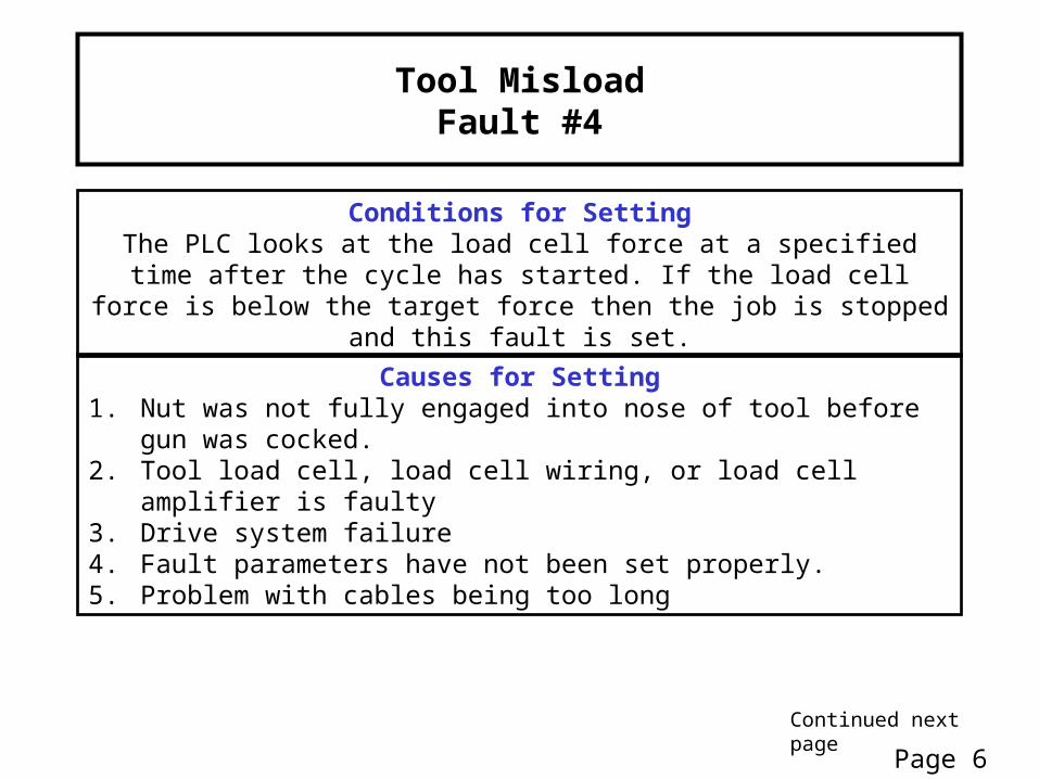
Conditions for SettingThe PLC looks at the load cell force at a specified time after the cycle has
started. If the load cell force is below the target force then the job is stopped and this fault is set.
Causes for Setting1. Nut was not fully engaged into nose of tool before gun was cocked.2. Tool load cell, load cell wiring, or load cell amplifier is faulty3. Drive system failure4. Fault parameters have not been set properly.5. Problem with cables being too long
Page 6Continued next page

Tool MisloadFault #4
Troubleshooting
TroubleshootingIf tool is not installed correctly then install correctly and restart job
If this is a new installation or there is a product change then fault parameters have to be developed. See Developing Misload Parameters
If tool was installed correctly and fault parameters have been developed then run a Verification cycle on the cal stand. If you still get a Tool Misload fault then see: Drive System Troubleshooting & Repair.
If a different fault code is set on the cal stand then follow the troubleshooting for that fault code.
Page 7
Reverse Revolutions Time OutFault #5
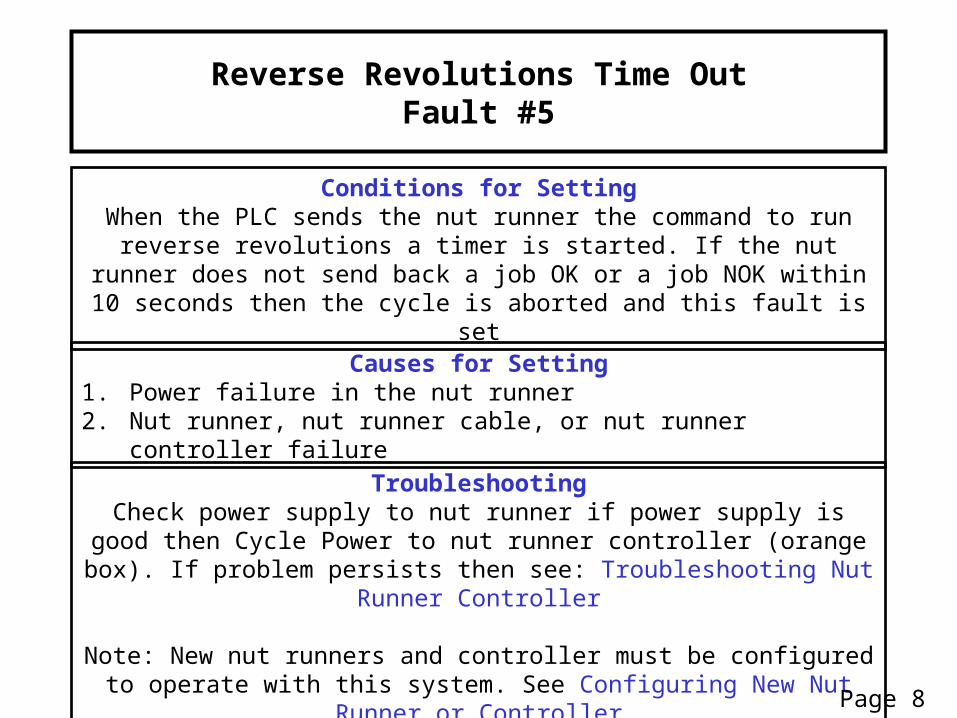
Conditions for SettingWhen the PLC sends the nut runner the command to run reverse
revolutions a timer is started. If the nut runner does not send back a job OK or a job NOK within 10 seconds then the cycle is aborted and this fault is
set
TroubleshootingCheck power supply to nut runner if power supply is good then Cycle
Power to nut runner controller (orange box). If problem persists then see: Troubleshooting Nut Runner Controller
Note: New nut runners and controller must be configured to operate with this system. See Configuring New Nut Runner or Controller
Causes for Setting1. Power failure in the nut runner2. Nut runner, nut runner cable, or nut runner controller failure
Page 8
Tool Load Cell Maximum Force ExceededFault #6
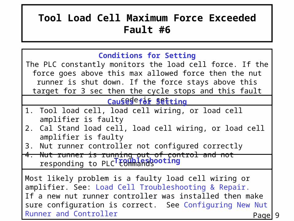
Conditions for SettingThe PLC constantly monitors the load cell force. If the force goes above
this max allowed force then the nut runner is shut down. If the force stays above this target for 3 sec then the cycle stops and this fault code is set.
Troubleshooting
Most likely problem is a faulty load cell wiring or amplifier. See: Load Cell Troubleshooting & Repair.If a new nut runner controller was installed then make sure configuration is correct. See Configuring New Nut Runner and Controller
Causes for Setting1. Tool load cell, load cell wiring, or load cell amplifier is faulty2. Cal Stand load cell, load cell wiring, or load cell amplifier is faulty3. Nut runner controller not configured correctly4. Nut runner is running out of control and not responding to PLC
commands
Page 9

Calibration Load Cell Maximum Force ExceededFault #7
Conditions for SettingThe PLC constantly monitors the cal stand load cell force. If the force goes above the maximum allowed target then the cycle stops and this fault code
is set. This fault is not active in Auto Cycle. In manual cal mode it will sound the alarm but will not stop the cycle from running.
TroubleshootingMost likely problem is a faulty load cell wiring or amplifier. See: Load Cell Troubleshooting & Repair.If a new nut runner controller was installed then make sure configuration is correct. See Configuring New Nut Runner and Controller
Causes for Setting1. Cal stand load cell, load cell wiring, or load cell amplifier is faulty2. Tool load cell, load cell wiring, or load cell amplifier is faulty3. Nut runner controller not configured correctly4. Nut runner is running out of control and not responding to PLC
commands
Page 10

Calibration Load Cell Outside Zero Offset RangeFault #8
Conditions for SettingWhen zero offset button is pressed the cal stand load cell reading is
greater than 10 Lbs (HMI Configurable). This is an indication that there is force already applied to the cal stand or the cal stand load cell is faulty.
TroubleshootingIf no force is being applied to the cal stand load cell then see Cal Stand
Load Cell Troubleshooting & Repair
Causes for Setting1. Force is being applied to the cal stand when the zero offset is pressed2. Cal stand load cell, load cell wiring, or amplifier is faulty.3. Cal stand load cell requires re-calibration.
Page 11

Current Load Cell Reading Too High to Start CalibrationFault #10
Conditions for SettingThe PLC looks at the tool load cell force and cal stand load cell when the
cycle start button is pressed. If the load cell force is above 10 lbs (HMI Configurable) then the job is stopped and this fault is set.
TroubleshootingRemove tool from stand, make sure nut is backed off so that no load is on cal stand. Press Fault reset and Zero Offset button. Install tool to cal stand and restart cycle being sure there is no load being applied to the threaded rod. If problem persists then check load cell readings on PV calibration screen. If calibration load cell is reading high then see: Cal Stand Load Cell Troubleshooting & Repair. If tool load cell reading is high then see: Tool Load Cell Troubleshooting & Repair
Causes for Setting1. Load is being applied to tool prior to calibration cycle start.2. Faulty Load cell, load cell wiring, or load cell amplifier.
Page 12
Tool Removed During Fast RunFault #11
Conditions for SettingThe PLC looks at the tool load cell force and once it reached a user
defined lower limit if the load cell force drops back below this limit during the fast run part of the cycle then this fault is set. The force must stay
below the limit for a specified amount of time (HMI Configurable) before this alarm is set.
TroubleshootingIf release ring was pulled then reinstall tool on job and restart cycle.If the tool came off the job but the release ring was not pulled then see Cocking System Troubleshooting & RepairIf the tool is still connected to the job then see Load Cell Troubleshooting & Repair
Causes for Setting1. Operator pulls release ring during the cycle2. Quick connect system malfunction3. Faulty Load cell, load cell wiring, or load cell amplifier.
Page 13

Calibration Mode Jog Forward TimeoutFault #13
Conditions for SettingCalibration cycle runs for 30 seconds without achieving target force
TroubleshootingIf tool is properly connected then see: Cal Stand Load Cell Troubleshooting
& Repair
Causes for Setting1. Tool not properly installed on calibration stand.2. Faulty load cell, load cell wiring, or load cell amplifier
Page 14
Calibration Zero Offset Not Complete Before Pressing Start
Fault #14
Conditions for SettingBefore starting calibration the load cells must be zeroed by pressing the “Set Zero Offset” button. If the zero offset is not pressed prior to pressing
the start trigger then this fault is set.
TroubleshootingRemove tool from calibration stand, press “Set Zero Offset” button, reinstall
tool and press the start button
Causes for Setting1. Zero offset not set before starting calibration cycle
Page 15

Calibration Cycle TimeoutFault #15
Conditions for SettingCalibration cycle not complete within the 45 second allowed cycle time
TroubleshootingCycle power to nut runner and restart calibration.
If problem persists the see: Manual Calibration Procedure
Causes for Setting1. Unknown error occurs
Page 16

Fast Run Tension Not AchievedFault #16
Conditions for SettingFast run tension is not achieved within the max allowed cycle time.
Fast run tension and cycle time are configurable in parameter screen
TroubleshootingRun tool on calibration stand and follow fault codes set on cal stand.
Causes for Setting1. Unknown error occurs
Page 17

Tool not CockedFault #17
Conditions for SettingThe PLC looks for the prox switch to be closed before it will allow the cycle to start. If the start switch is pressed without the prox switch being closed the cycle will not start and the alarm is sounded until the tool is cocked.
TroubleshootingPull release ring, unclamp anti rotation and reinstall tool and restart job.If tool is properly loaded and cocked and fault still occurs then see Prox Switch Troubleshooting & Repair
Causes for Setting1. The tool is not cocked when the start switch is pressed.2. Defective prox switch or prox switch wiring.
Page 18
Nut Runner Over Torque WarningSets PM Required
Conditions for SettingIf the nut runner exceeds the maximum allowed torque during the tensioning process it will send a job complete NOK signal to the PLC. If the PLC receives this NOK signal during the tensioning part of the process then the process will continue and the job will be evaluated based on the tension achieved. If the tension is within the acceptable range then the job will be accepted and this warning is set. The warning turns on the yellow stack light and sets a PM required code in the PM screen in the PV but does to fail the job.
Causes for Setting1. Loss of grease in crows foot, angle head, or thrust bearing in end effector2. Broken or worn gears in angle head or crows foot.3. Worn thrust bearing in end effector.4. Damaged threads on nut or threaded rod in cable system5. Internal error in nut runner controller
Page 19Continued next page
Nut Runner Over Torque WarningTroubleshooting
Troubleshooting
On nut runner panel review the history screen to see what nut runner fault was set during this cycle.
To access the history screen:1. Plug the keyboard and mouse into the USB port on the bottom of the nut runner control
box2. From the top menu select “Navigate” then “Statistics”3. In the statistics screen select the “Chronological History” tab.4. Near the top of the list there should be a job that failed. Find this failed job and look for the
reason it failed. 1. If High Torque fault is set then this is an indication that the angle head, crows foot,
and the end effector thrust bearing require PM. See Drive System PM2. If some other nut runner fault occurred then cycle power to the nut runner controller.
If the problem persists then replace nut runner and nut runner box and send them back for repair.
5. If no fault is found in the Cooper box then see Drive System PM
Page 20

Nut Runner Over Torque FaultFault #19
Conditions for SettingIf the nut runner exceeds the maximum allowed torque during the tensioning process it will send a job complete NOK signal to the PLC. If the PLC receives this NOK signal during the tensioning part of the process then the process will continue and the job will be evaluated based on the tension achieved. If the tension is below the acceptable range then the job will be failed and this fault set.
Causes for Setting1. Loss of grease in crows foot, angle head, or thrust bearing in end
effector2. Broken or worn gears in angle head or crows foot.3. Worn thrust bearing in end effector.4. Damaged threads on nut or threaded rod in cable system5. Internal error in nut runner controller
Page 21Continued next page

Nut Runner Over Torque FaultFault #19
Troubleshooting
Troubleshooting
On nut runner panel review the history screen to see what nut runner fault was set during this cycle.
To access the history screen:1. Plug the keyboard and mouse into the USB port on the bottom of the nut runner control
box2. From the top menu select “Navigate” then “Statistics”3. In the statistics screen select the “Chronological History” tab.4. Near the top of the list there should be a job that failed. Find this failed job and look for the
reason it failed. 1. If High Torque fault is set then this is an indication that the angle head, crows foot,
and the end effector thrust bearing require PM. See Drive System PM2. If some other nut runner fault occurred then cycle power to the nut runner controller.
If the problem persists then replace nut runner and nut runner box and send them back for repair.
5. If no fault is found in the Cooper box then see Drive System PM
Page 22

Reverse Revolutions not CompleteFault #20
Conditions for SettingThe nut runner control panel sends a job NOK signal to the PLC during the
reverse revolutions sequence. The cycle stops and fault is set.
Causes for Setting1. Nut runner went over torque2. Some other nut runner fault
Page 23
Continued next page

Reverse Revolutions not Complete Fault #20Troubleshooting
Troubleshooting
On nut runner panel review the history screen to see what nut runner fault was set during this cycle.
To access the history screen:1. Plug the keyboard and mouse into the USB port on the bottom of the nut runner control
box2. From the top menu select “Navigate” then “Statistics”3. In the statistics screen select the “Chronological History” tab.4. Near the top of the list there should be a job that failed. Find this failed job and look for the
reason it failed. 1. If High Torque fault is set then this is an indication that the angle head, crows foot,
and the end effector thrust bearing require PM. See Drive System PM2. If some other nut runner fault occurred then cycle power to the nut runner controller.
If the problem persists then see: Troubleshooting Nut Runner Controller5. If no fault is found in the Cooper box then see Drive System PM
Page 24

Tool & Cal Load Cells Excessive Difference Fault #21
Conditions for SettingTool load cell reading and calibration load cell reading are more than 100
lbs apart during the calibration cycle.
Causes for Setting1. Calibration load cell unplugged from panel2. Calibration or tool load cell is severely out of calibration.3. Calibration or tool load cell is faulty
Page 25
Continued next page

Tool &Cal Load Cells Excessive Difference Fault #21
Troubleshooting
Troubleshooting
1. Check to be sure cal stand load cell is plugged in. If unplugged then plug in and rerun cycle.2. See Load Cell Troubleshooting & Repair.
Page 26

Final Tension Over Force FaultFault #32
Conditions for SettingIf the final tension achieved is over the maximum allowable force this fault
is set
TroubleshootingCheck accept delta limit in the parameter screen this should not be set to less than 50 lbs
See Tool Load Cell Troubleshooting & Repair
If problem is not found then change nut runner controller
Causes for Setting1. Faulty tool load cell, load cell wiring, or load cell amplifier.2. Faulty nut runner controller3. Parameters set up wrong
Page 27

Final Tension Under Force FaultFault #33
Conditions for SettingIf the final tension achieved is under the minimum allowable force this fault
is set
TroubleshootingCheck accept delta limit in the parameter screen this should not be set to less than 50 lbsSee Nut Runner Over Torque Fault #18See Tool Load Cell Troubleshooting & Repair
Causes for Setting1. Nut runner shuts down due to over torque condition2. Faulty tool load cell, load cell wiring, or load cell amplifier.3. Faulty nut runner controller4. Parameters set up wrong
Page 28

Calibration Failed
Conditions for Setting
Load cell gain factor is >1.5 or < .75
During the calibration cycle the PLC the compares the force measured by the calibration stand and the force measured by the tool. It then calculated a gain factor that is applied to the tool load cell so that the force readings
match. If this gain factor is outside to allowable limits then it is an indication that the tool load cell is not working properly.
Causes for Setting1. Tool misbuilt – Load cell installed upside down will trigger this fault2. Faulty tool load cell, load cell wiring, or load cell amplifier3. Faulty cal stand load cell, load cell wiring, or load cell amplifier
Page 29

Calibration FailedTroubleshooting
Page 30
Troubleshooting
1. Check to be sure cal stand load cell is plugged in. If unplugged then plug in and rerun cycle.2. If this is the first time the end effector has been used after being serviced the check to be sure the
load cell is installed correctly.3. If Load cell is installed correctly then see Load Cell Troubleshooting & Repair.