tons - usesi careers
TRANSCRIPT
Control and IndicationPushbuttons
30.5 mm PushbuttonsT series & E34
Control and indication
2 Eaton 30.5 mm Pushbuttons
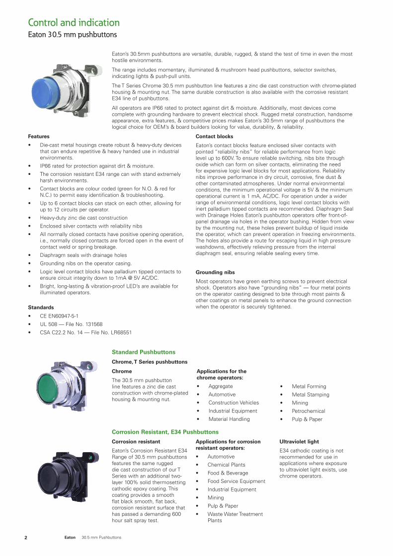
Eaton’s 30.5mm pushbuttons are versatile, durable, rugged, & stand the test of time in even the most hostile environments.
The range includes momentary, illuminated & mushroom head pushbuttons, selector switches, indicating lights & push-pull units.
The T Series Chrome 30.5 mm pushbutton line features a zinc die cast construction with chrome-plated housing & mounting nut. The same durable construction is also available with the corrosive resistant E34 line of pushbuttons.
All operators are IP66 rated to protect against dirt & moisture. Additionally, most devices come complete with grounding hardware to prevent electrical shock. Rugged metal construction, handsome appearance, extra features, & competitive prices makes Eaton’s 30.5mm range of pushbuttons the logical choice for OEM’s & board builders looking for value, durability, & reliability.
Features
• Die-cast metal housings create robust & heavy-duty devices that can endure repetitive & heavy handed use in industrial environments.
• IP66 rated for protection against dirt & moisture.
• The corrosion resistant E34 range can with stand extremely harsh environments.
• Contact blocks are colour coded (green for N.O. & red for N.C.) to permit easy identification & troubleshooting.
• Up to 6 contact blocks can stack on each other, allowing for up to 12 circuits per operator.
• Heavy-duty zinc die cast construction
• Enclosed silver contacts with reliability nibs
• All normally closed contacts have positive opening operation, i.e., normally closed contacts are forced open in the event of contact weld or spring breakage.
• Diaphragm seals with drainage holes
• Grounding nibs on the operator casing.
• Logic level contact blocks have palladium tipped contacts to ensure circuit integrity down to 1mA @ 5V AC/DC.
• Bright, long-lasting & vibration-proof LED’s are available for illuminated operators.
Standards
• CE EN60947-5-1
• UL 508 — File No. 131568
• CSA C22.2 No. 14 — File No. LR68551
Contact blocks
Eaton’s contact blocks feature enclosed silver contacts with pointed “reliability nibs” for reliable performance from logic level up to 600V. To ensure reliable switching, nibs bite through oxide which can form on silver contacts, eliminating the need for expensive logic level blocks for most applications. Reliability nibs improve performance in dry circuit, corrosive, fine dust & other contaminated atmospheres. Under normal environmental conditions, the minimum operational voltage is 5V & the minimum operational current is 1 mA, AC/DC. For operation under a wider range of environmental conditions, logic level contact blocks with inert palladium tipped contacts are recommended. Diaphragm Seal with Drainage Holes Eaton’s pushbutton operators offer front-of-panel drainage via holes in the operator bushing. Hidden from view by the mounting nut, these holes prevent buildup of liquid inside the operator, which can prevent operation in freezing environments. The holes also provide a route for escaping liquid in high pressure washdowns, effectively relieving pressure from the internal diaphragm seal, ensuring reliable sealing every time.
Grounding nibs
Most operators have green earthing screws to prevent electrical shock. Operators also have “grounding nibs” — four metal points on the operator casting designed to bite through most paints & other coatings on metal panels to enhance the ground connection when the operator is securely tightened.
Standard Pushbuttons
Chrome, T Series pushbuttons
Chrome
The 30.5 mm pushbutton line features a zinc die cast construction with chrome-plated housing & mounting nut.
Applications for the chrome operators:
• Aggregate
• Automotive
• Construction Vehicles
• Industrial Equipment
• Material Handling
• Metal Forming
• Metal Stamping
• Mining
• Petrochemical
• Pulp & Paper
Corrosion resistant
Eaton’s Corrosion Resistant E34 Range of 30.5 mm pushbuttons features the same rugged die cast construction of our T Series with an additional two-layer 100% solid thermosetting cathodic epoxy coating. This coating provides a smooth flat black smooth, flat back, corrosion resistant surface that has passed a demanding 600 hour salt spray test.
Applications for corrosion resistant operators:
• Automotive
• Chemical Plants
• Food & Beverage
• Food Service Equipment
• Industrial Equipment
• Mining
• Pulp & Paper
• Waste Water Treatment Plants
Ultraviolet light
E34 cathodic coating is not recommended for use in applications where exposure to ultraviolet light exists, use chrome operators.
Corrosion Resistant, E34 Pushbuttons
Eaton 30.5 mm pushbuttons
Control and indication
3Eaton 30.5 mm Pushbuttons
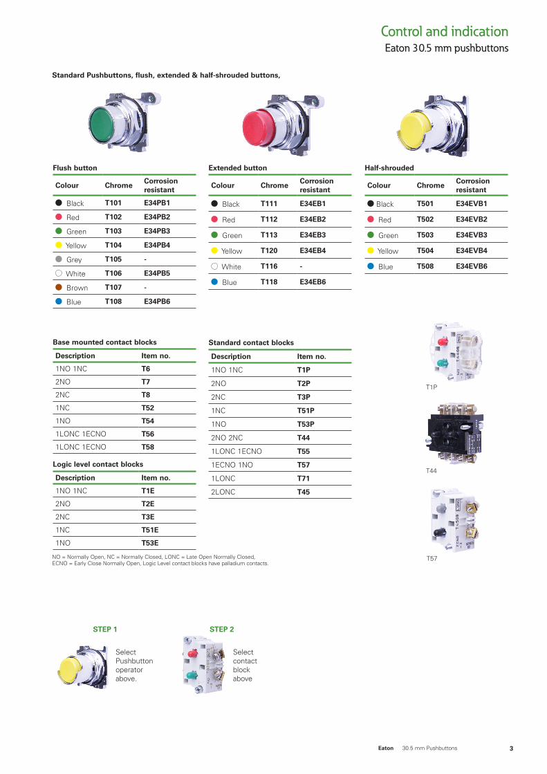
Standard Pushbuttons, flush, extended & half-shrouded buttons,
Half-shrouded
Colour ChromeCorrosion resistant
Black T501 E34EVB1
Red T502 E34EVB2
Green T503 E34EVB3
Yellow T504 E34EVB4
Blue T508 E34EVB6
Extended button
Colour ChromeCorrosion resistant
Black T111 E34EB1
Red T112 E34EB2
Green T113 E34EB3
Yellow T120 E34EB4
White T116 -
Blue T118 E34EB6
Flush button
Colour ChromeCorrosion resistant
Black T101 E34PB1
Red T102 E34PB2
Green T103 E34PB3
Yellow T104 E34PB4
Grey T105 -
White T106 E34PB5
Brown T107 -
Blue T108 E34PB6
Standard contact blocks
Description Item no.
1NO 1NC T1P
2NO T2P
2NC T3P
1NC T51P
1NO T53P
2NO 2NC T44
1LONC 1ECNO T55
1ECNO 1NO T57
1LONC T71
2LONC T45
Base mounted contact blocks
Description Item no.
1NO 1NC T6
2NO T7
2NC T8
1NC T52
1NO T54
1LONC 1ECNO T56
1LONC 1ECNO T58
Logic level contact blocks
Description Item no.
1NO 1NC T1E
2NO T2E
2NC T3E
1NC T51E
1NO T53E
NO = Normally Open, NC = Normally Closed, LONC = Late Open Normally Closed, ECNO = Early Close Normally Open, Logic Level contact blocks have palladium contacts.
Select Pushbutton operator above.
Select contact block above
STEP 1 STEP 2
Eaton 30.5 mm pushbuttons
T1P
T44
T57
Eaton 30.5 mm pushbuttonsControl and indication
4 Eaton 30.5 mm Pushbuttons
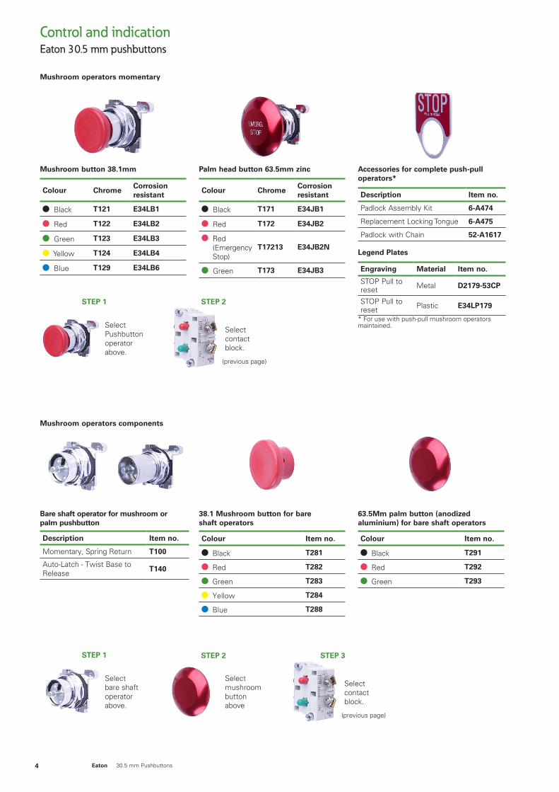
Mushroom operators momentary
Mushroom button 38.1mm
Colour ChromeCorrosion resistant
Black T121 E34LB1
Red T122 E34LB2
Green T123 E34LB3
Yellow T124 E34LB4
Blue T129 E34LB6
Palm head button 63.5mm zinc
Colour ChromeCorrosion resistant
Black T171 E34JB1
Red T172 E34JB2
Red (Emergency Stop)
T17213 E34JB2N
Green T173 E34JB3
Accessories for complete push-pull operators*
Description Item no.
Padlock Assembly Kit 6-A474
Replacement Locking Tongue 6-A475
Padlock with Chain 52-A1617
Legend Plates
Engraving Material Item no.
STOP Pull to reset Metal D2179-53CP
STOP Pull to reset Plastic E34LP179
* For use with push-pull mushroom operators maintained.Select
Pushbutton operator above.
STEP 1
Select contact block.
STEP 2
(previous page)
Mushroom operators components
Bare shaft operator for mushroom or palm pushbutton
Description Item no.
Momentary, Spring Return T100
Auto-Latch - Twist Base to Release T140
38.1 Mushroom button for bare shaft operators
Colour Item no.
Black T281
Red T282
Green T283
Yellow T284
Blue T288
63.5Mm palm button (anodized aluminium) for bare shaft operators
Colour Item no.
Black T291
Red T292
Green T293
Select bare shaft operator above.
STEP 1
Select mushroom button above
STEP 2
Select contact block.
STEP 3
(previous page)
Eaton 30.5 mm pushbuttonsControl and indication
5Eaton 30.5 mm Pushbuttons
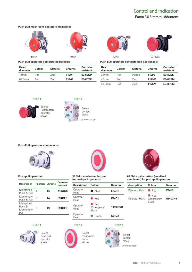
Push-pull mushroom operators maintained
Push-pull operators complete padlockable
Head diameter
Colour Material ChromeCorrosion resistant
45mm Red Zinc T129P E34129P
63.5mm Red Zinc T176P E34176P
Push-pull operators complete non-padlockable
Head diameter
Colour Material ChromeCorrosion resistant
38mm Red Plastic T129S E34129S
45mm Red Zinc T129M E34129M
63.5mm Red Zinc T176M E34176M
Select Pushbutton operator above.
STEP 1
Select contact block.
STEP 2
(previous page)
Push-pull operators
Description Position Chrome Corrosion resistant
Maintained Push & Pull 2 T5 E34GDB
Momentary Push & Pull 3 T4 E34GEB
Maintained Push & Momentary Pull
3 T9 E34GFB
38.1Mm mushroom button for push-pull operators
Description Colour Item no.
Operator Head Black E34C1
Operator Head Red E34C2
Operator Head
Red (Emergency Stop)
10250TB63
Operator Head Green E34C3
63.5Mm palm button (anodized aluminium) for push-pull operators
description Colour Item no.
Operator Head Red E34J2
Operator Head Red
(Emergency Stop)
E34J2N8
Push-Pull operators components
Select push-pull operator above.
STEP 1
Select mushroom button above
STEP 2
Select contact block.
STEP 3
(previous page)
T129P T176P E34129ST129M
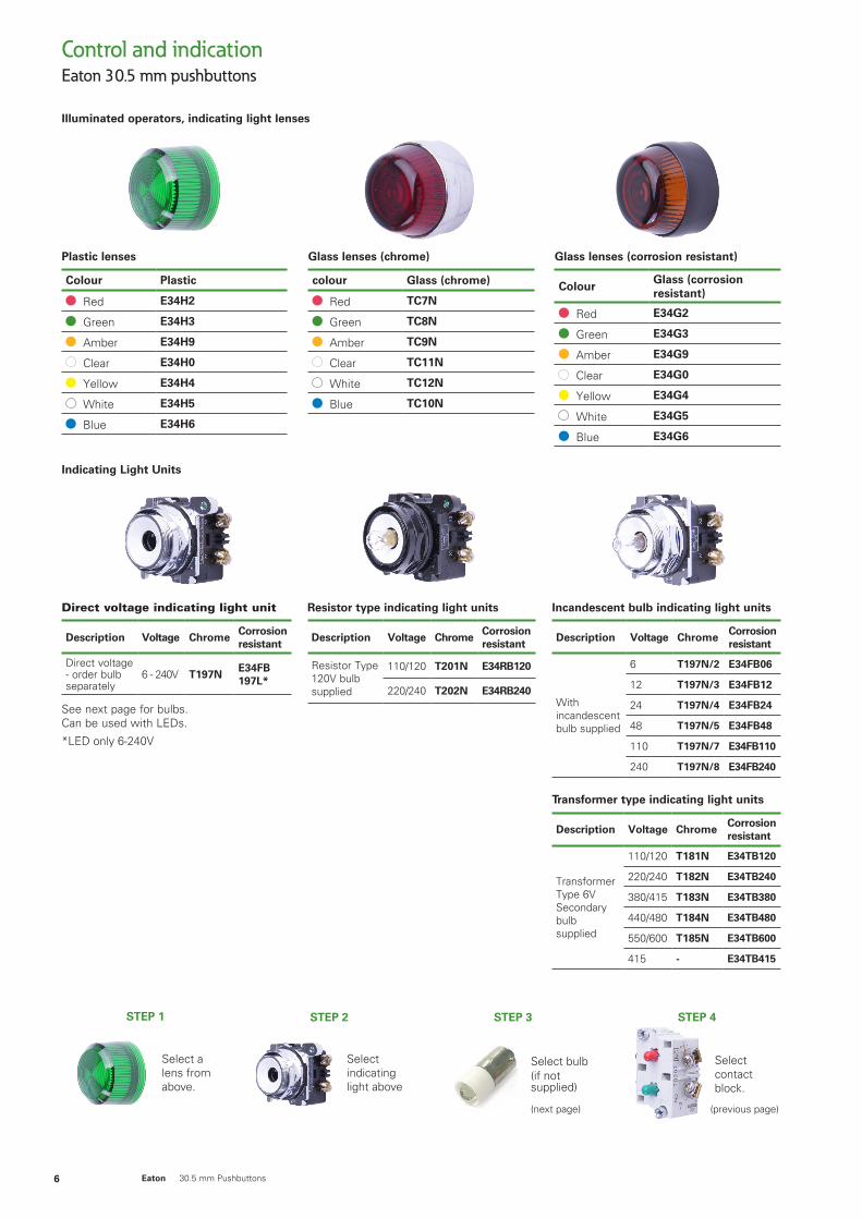
Illuminated operators, indicating light lenses
Eaton 30.5 mm pushbuttonsControl and indication
6 Eaton 30.5 mm Pushbuttons
Select a lens from above.
STEP 1
Indicating Light Units
Plastic lenses
Colour Plastic
Red E34H2
Green E34H3
Amber E34H9
Clear E34H0
Yellow E34H4
White E34H5
Blue E34H6
Glass lenses (chrome)
colour Glass (chrome)
Red TC7N
Green TC8N
Amber TC9N
Clear TC11N
White TC12N
Blue TC10N
Glass lenses (corrosion resistant)
ColourGlass (corrosion resistant)
Red E34G2
Green E34G3
Amber E34G9
Clear E34G0
Yellow E34G4
White E34G5
Blue E34G6
Incandescent bulb indicating light units
Description Voltage ChromeCorrosion resistant
With incandescent bulb supplied
6 T197N/2 E34FB06
12 T197N/3 E34FB12
24 T197N/4 E34FB24
48 T197N/5 E34FB48
110 T197N/7 E34FB110
240 T197N/8 E34FB240
Transformer type indicating light units
Description Voltage ChromeCorrosion resistant
Transformer Type 6V Secondarybulb supplied
110/120 T181N E34TB120
220/240 T182N E34TB240
380/415 T183N E34TB380
440/480 T184N E34TB480
550/600 T185N E34TB600
415 - E34TB415
Resistor type indicating light units
Description Voltage ChromeCorrosion resistant
Resistor Type120V bulb supplied
110/120 T201N E34RB120
220/240 T202N E34RB240
Select indicating light above
STEP 2
Select bulb(if not supplied)
STEP 3
(next page)
Select contact block.
STEP 4
(previous page)
Direct voltage indicating light unit
Description Voltage ChromeCorrosion resistant
Direct voltage - order bulb separately
6 - 240V T197NE34FB 197L*
See next page for bulbs. Can be used with LEDs.
*LED only 6-240V
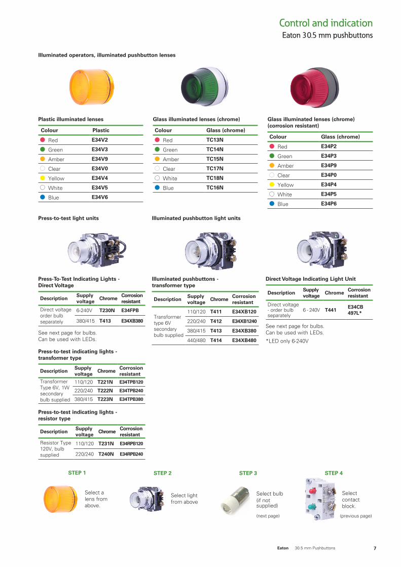
Illuminated operators, illuminated pushbutton lenses
Eaton 30.5 mm pushbuttonsControl and indication
7Eaton 30.5 mm Pushbuttons
Select a lens from above.
STEP 1
Select light from above
STEP 2
Select bulb(if not supplied)
STEP 3
(next page)
Select contact block.
STEP 4
(previous page)
Plastic illuminated lenses
Colour Plastic
Red E34V2
Green E34V3
Amber E34V9
Clear E34V0
Yellow E34V4
White E34V5
Blue E34V6
Glass illuminated lenses (chrome)
Colour Glass (chrome)
Red TC13N
Green TC14N
Amber TC15N
Clear TC17N
White TC18N
Blue TC16N
Glass illuminated lenses (chrome) (corrosion resistant)
Colour Glass (chrome)
Red E34P2
Green E34P3
Amber E34P9
Clear E34P0
Yellow E34P4
White E34P5
Blue E34P6
Direct Voltage Indicating Light Unit
DescriptionSupply voltage
ChromeCorrosion resistant
Direct voltage - order bulb separately
6 - 240V T441E34CB 497L*
See next page for bulbs. Can be used with LEDs.
*LED only 6-240V
Illuminated pushbuttons - transformer type
DescriptionSupply voltage
ChromeCorrosion resistant
Transformer type 6V secondarybulb supplied
110/120 T411 E34XB120
220/240 T412 E34XB1240
380/415 T413 E34XB380
440/480 T414 E34XB480
Press-To-Test Indicating Lights - Direct Voltage
DescriptionSupply voltage
ChromeCorrosion resistant
Direct voltageorder bulb separately
6-240V T230N E34FPB
380/415 T413 E34XB380
See next page for bulbs. Can be used with LEDs.
Press-to-test indicating lights - transformer type
DescriptionSupply voltage
ChromeCorrosion resistant
Transformer Type 6V, 1W secondarybulb supplied
110/120 T221N E34TPB120
220/240 T222N E34TPB240
380/415 T223N E34TPB380
Press-to-test indicating lights - resistor type
DescriptionSupply voltage
ChromeCorrosion resistant
Resistor Type120V, bulb supplied
110/120 T231N E34RPB120
220/240 T240N E34RPB240
Illuminated pushbutton light unitsPress-to-test light units
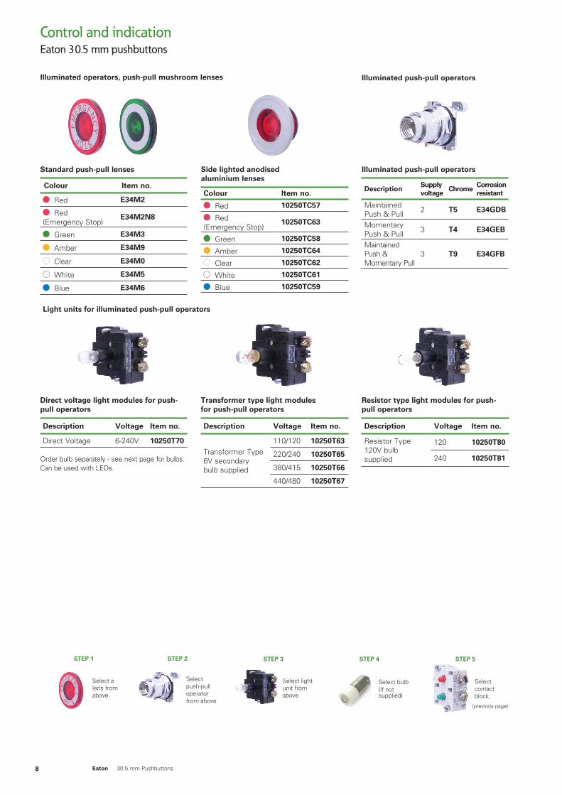
Illuminated operators, push-pull mushroom lenses
Eaton 30.5 mm pushbuttonsControl and indication
8 Eaton 30.5 mm Pushbuttons
Standard push-pull lenses
Colour Item no.
Red E34M2
Red (Emergency Stop)
E34M2N8
Green E34M3
Amber E34M9
Clear E34M0
White E34M5
Blue E34M6
Side lighted anodised aluminium lenses
Colour Item no.
Red 10250TC57
Red (Emergency Stop)
10250TC63
Green 10250TC58
Amber 10250TC64
Clear 10250TC62
White 10250TC61
Blue 10250TC59
Illuminated push-pull operators
DescriptionSupply voltage
ChromeCorrosion resistant
Maintained Push & Pull 2 T5 E34GDB
Momentary Push & Pull 3 T4 E34GEB
Maintained Push & Momentary Pull
3 T9 E34GFB
Illuminated push-pull operators
Light units for illuminated push-pull operators
Resistor type light modules for push-pull operators
Description Voltage Item no.
Resistor Type120V bulbsupplied
120 10250T80
240 10250T81
Direct voltage light modules for push-pull operators
Description Voltage Item no.
Direct Voltage 6-240V 10250T70
Order bulb separately - see next page for bulbs. Can be used with LEDs.
Transformer type light modules for push-pull operators
Description Voltage Item no.
Transformer Type6V secondarybulb supplied
110/120 10250T63
220/240 10250T65
380/415 10250T66
440/480 10250T67
Select push-pull operator from above
Select a lens from above.
STEP 2STEP 1
Select light unit from above
STEP 3
Select bulb(if not supplied)
STEP 4
Select contact block.
STEP 5
(previous page)
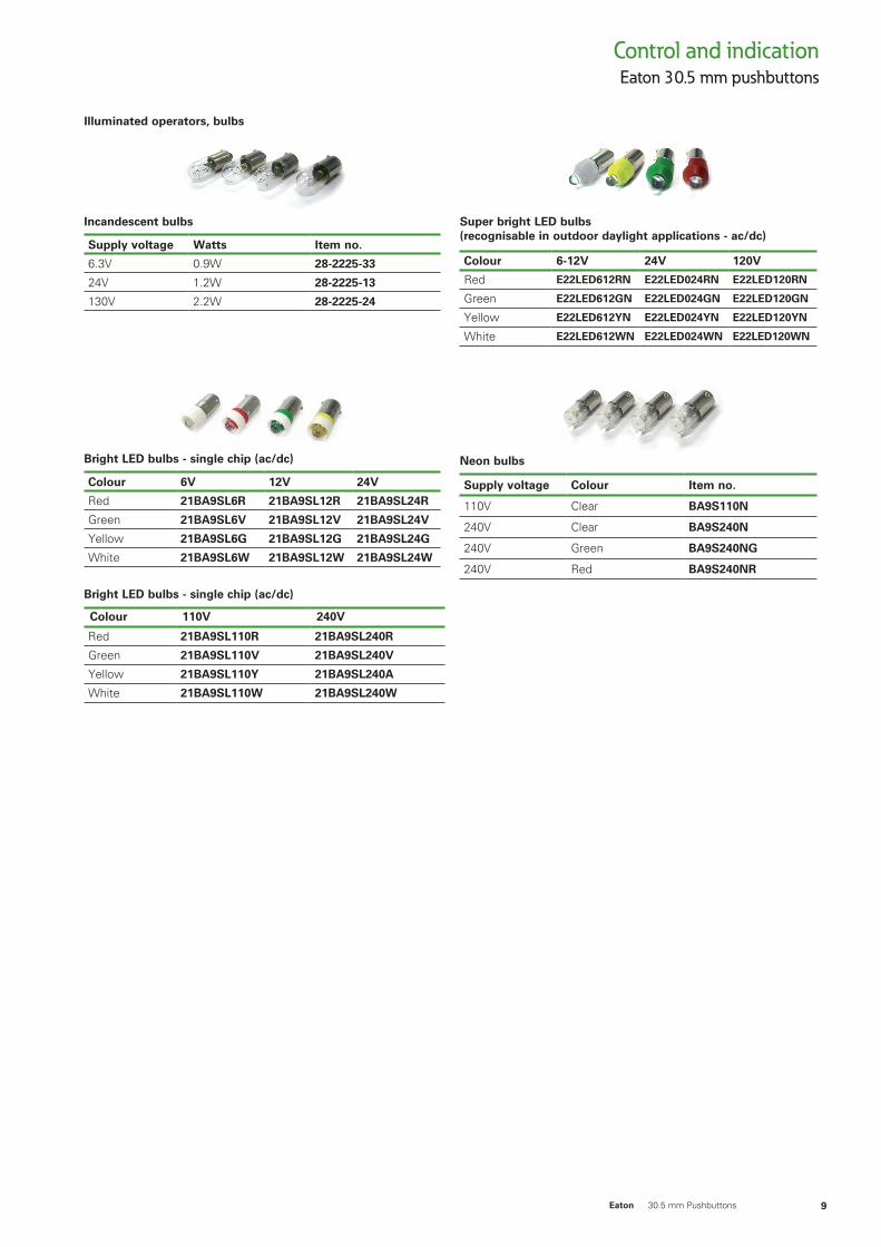
Illuminated operators, bulbs
Eaton 30.5 mm pushbuttonsControl and indication
9Eaton 30.5 mm Pushbuttons
Incandescent bulbs
Supply voltage Watts Item no.
6.3V 0.9W 28-2225-33
24V 1.2W 28-2225-13
130V 2.2W 28-2225-24
Bright LED bulbs - single chip (ac/dc)
Colour 6V 12V 24V
Red 21BA9SL6R 21BA9SL12R 21BA9SL24R
Green 21BA9SL6V 21BA9SL12V 21BA9SL24V
Yellow 21BA9SL6G 21BA9SL12G 21BA9SL24G
White 21BA9SL6W 21BA9SL12W 21BA9SL24W
Bright LED bulbs - single chip (ac/dc)
Colour 110V 240V
Red 21BA9SL110R 21BA9SL240R
Green 21BA9SL110V 21BA9SL240V
Yellow 21BA9SL110Y 21BA9SL240A
White 21BA9SL110W 21BA9SL240W
Super bright LED bulbs (recognisable in outdoor daylight applications - ac/dc)
Colour 6-12V 24V 120V
Red E22LED612RN E22LED024RN E22LED120RN
Green E22LED612GN E22LED024GN E22LED120GN
Yellow E22LED612YN E22LED024YN E22LED120YN
White E22LED612WN E22LED024WN E22LED120WN
Neon bulbs
Supply voltage Colour Item no.
110V Clear BA9S110N
240V Clear BA9S240N
240V Green BA9S240NG
240V Red BA9S240NR
Selector switch operators,
Eaton 30.5 mm pushbuttonsControl and indication
10 Eaton 30.5 mm Pushbuttons
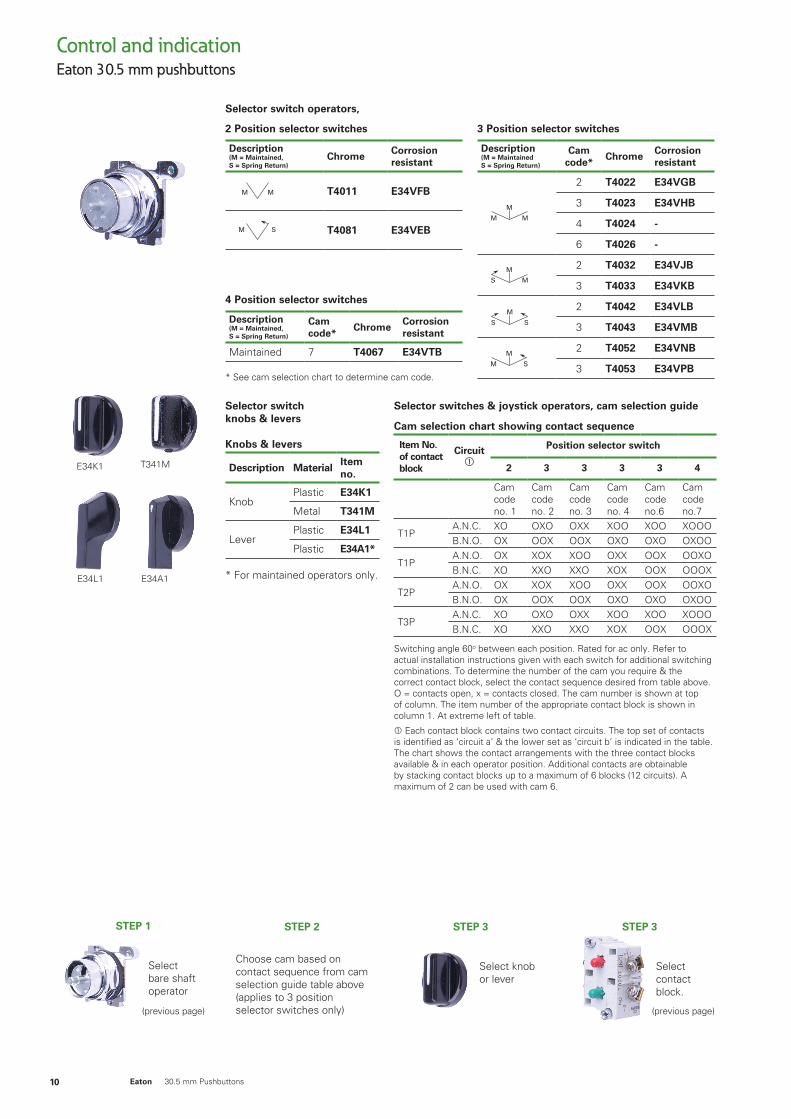
Selector switch knobs & levers
Knobs & levers
Description MaterialItem no.
KnobPlastic E34K1
Metal T341M
LeverPlastic E34L1
Plastic E34A1*
* For maintained operators only.
2 Position selector switches
Description(M = Maintained, S = Spring Return)
ChromeCorrosion resistant
M M
M M
M
M S
M
M S
MS
M
S S
M
M M
M M
T4011 E34VFB
M M
M M
M
M S
M
M S
MS
M
S S
M
M M
M M
T4081 E34VEB
4 Position selector switches
Description(M = Maintained, S = Spring Return)
Cam code*
ChromeCorrosion resistant
Maintained 7 T4067 E34VTB
* See cam selection chart to determine cam code.
3 Position selector switches
Description(M = Maintained S = Spring Return)
Cam code*
ChromeCorrosion resistantM M
M M
M
M S
M
M S
MS
M
S S
M
M M
M M
2 T4022 E34VGB
3 T4023 E34VHB
4 T4024 -
6 T4026 -
M M
M M
M
M S
M
M S
MS
M
S S
M
M M
M M
2 T4032 E34VJB
3 T4033 E34VKB
M M
M M
M
M S
M
M S
MS
M
S S
M
M M
M M
2 T4042 E34VLB
3 T4043 E34VMB
M M
M M
M
M S
M
M S
MS
M
S S
M
M M
M M
2 T4052 E34VNB
3 T4053 E34VPB
Selector switches & joystick operators, cam selection guide
Cam selection chart showing contact sequence
Item No. of contact block
Circuit
Position selector switch
2 3 3 3 3 4
Cam code no. 1
Cam code no. 2
Cam code no. 3
Cam code no. 4
Cam code no.6
Cam code no.7
T1PA.N.C. XO OXO OXX XOO XOO XOOO B.N.O. OX OOX OOX OXO OXO OXOO
T1PA.N.O. OX XOX XOO OXX OOX OOXO B.N.C. XO XXO XXO XOX OOX OOOX
T2PA.N.O. OX XOX XOO OXX OOX OOXO B.N.O. OX OOX OOX OXO OXO OXOO
T3PA.N.C. XO OXO OXX XOO XOO XOOO B.N.C. XO XXO XXO XOX OOX OOOX
Switching angle 60o between each position. Rated for ac only. Refer to actual installation instructions given with each switch for additional switching combinations. To determine the number of the cam you require & the correct contact block, select the contact sequence desired from table above. O = contacts open, x = contacts closed. The cam number is shown at top of column. The item number of the appropriate contact block is shown in column 1. At extreme left of table.
Each contact block contains two contact circuits. The top set of contacts is identified as ‘circuit a’ & the lower set as ‘circuit b’ is indicated in the table. The chart shows the contact arrangements with the three contact blocks available & in each operator position. Additional contacts are obtainable by stacking contact blocks up to a maximum of 6 blocks (12 circuits). A maximum of 2 can be used with cam 6.
Select bare shaft operator
STEP 1
Choose cam based on contact sequence from cam selection guide table above (applies to 3 position selector switches only)
STEP 2
Select knob or lever
STEP 3
Select contact block.
STEP 3
(previous page)(previous page)
E34K1 T341M
E34L1 E34A1
Eaton 30.5 mm pushbuttonsControl and indication
11Eaton 30.5 mm Pushbuttons
Spare key
Description Item no.
Replacement Keys (2) TA152
Other key codes are available contact eaton for more information.
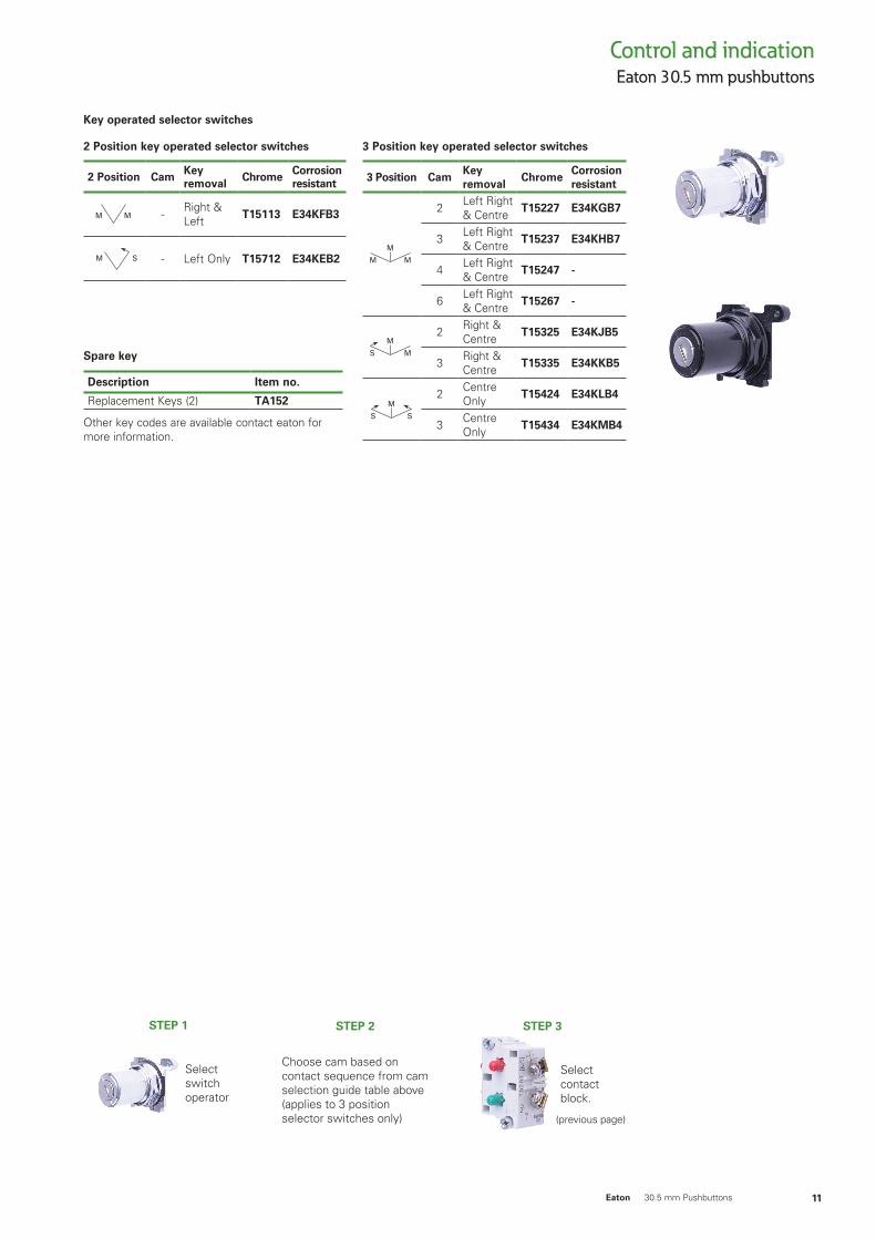
Key operated selector switches
2 Position key operated selector switches
2 Position Cam Key removal Chrome Corrosion
resistant
M M
M M
M
M S
M
M S
MS
M
S S
M
M M
M M
- Right & Left T15113 E34KFB3
M M
M M
M
M S
M
M S
MS
M
S S
M
M M
M M
- Left Only T15712 E34KEB2
3 Position key operated selector switches
3 Position CamKey removal
ChromeCorrosion resistant
M M
M M
M
M S
M
M S
MS
M
S S
M
M M
M M
2 Left Right & Centre T15227 E34KGB7
3 Left Right & Centre T15237 E34KHB7
4 Left Right & Centre T15247 -
6 Left Right & Centre T15267 -
M M
M M
M
M S
M
M S
MS
M
S S
M
M M
M M
2 Right & Centre T15325 E34KJB5
3 Right & Centre T15335 E34KKB5
M M
M M
M
M S
M
M S
MS
M
S S
M
M M
M M
2 Centre Only T15424 E34KLB4
3 Centre Only T15434 E34KMB4
Select switch operator
STEP 1
Choose cam based on contact sequence from cam selection guide table above (applies to 3 position selector switches only)
STEP 2
Select contact block.
STEP 3
(previous page)
Eaton 30.5 mm pushbuttonsControl and indication
12 Eaton 30.5 mm Pushbuttons
Maintained positions
Up Down Left Right Suffix No.*
X — — — 1 — X — — 2 — — X — 3 — — — X 4 X X — — 5 X — X — 6 X — — X 7 — X X — 8 — X — X 9 — — X X 10 X X X — 11 X X — X 12 X — X X 13 — X X X 14 X X X X 15
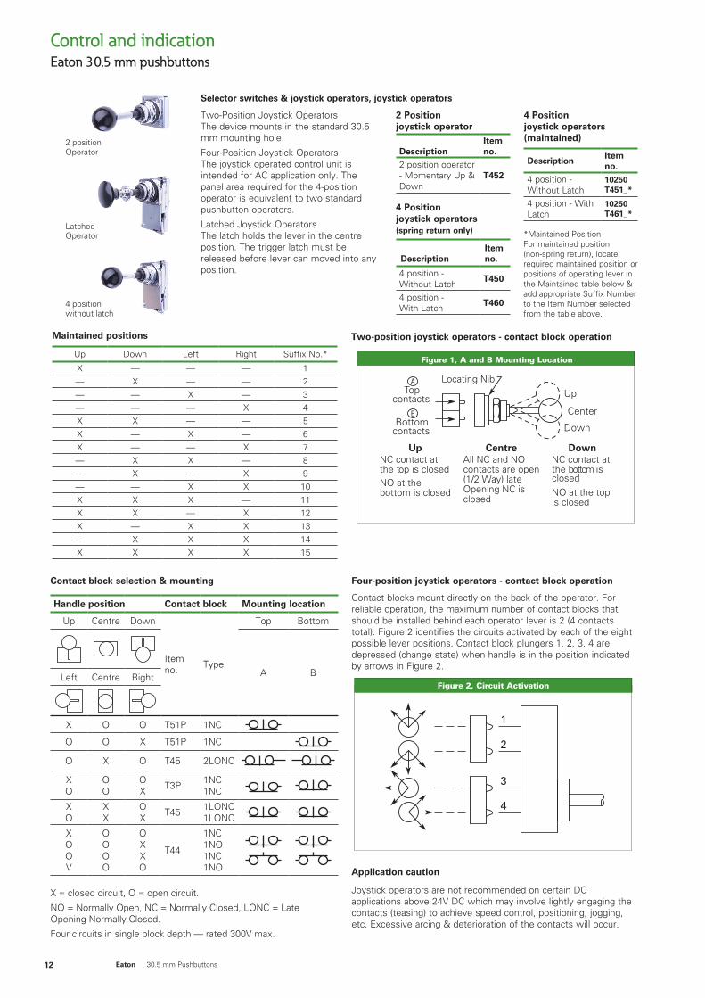
Two-position joystick operators - contact block operation
Figure 47-97. A and B Mounting Location
Up
Center
Down
Locating NibTop
contacts
Bottomcontacts
CentreAll NC and NOcontacts are open(1/2 Way) late Opening NC isclosed
UpNC contact atthe top is closedNO at the bottom is closed
DownNC contact atthe bottom is
NO at the top is closed
closed
Figure 1, A and B Mounting Location
Contact block selection & mounting
Handle position Contact block Mounting location
Up Centre Down
Item no. Type
Top Bottom
A BLeft Centre Right
X O O T51P 1NC
O O X T51P 1NC
O X O T45 2LONC
XO
OO
OX T3P 1NC
1NC
XO
XX
OX T45 1LONC
1LONC
XOOV
OOOO
OXXO
T44
1NC1NO1NC1NO
X = closed circuit, O = open circuit.
NO = Normally Open, NC = Normally Closed, LONC = Late Opening Normally Closed.
Four circuits in single block depth — rated 300V max.
Four-position joystick operators - contact block operation
Contact blocks mount directly on the back of the operator. For reliable operation, the maximum number of contact blocks that should be installed behind each operator lever is 2 (4 contacts total). Figure 2 identifies the circuits activated by each of the eight possible lever positions. Contact block plungers 1, 2, 3, 4 are depressed (change state) when handle is in the position indicated by arrows in Figure 2.
:tisiv noitamrofni erom roFE10020180AC www.eaton.com
1
2
3
4
Contact Blocks . . . . . . . . . . . . . . . . . . . Page 47-148Discount Symbol . . . . . . . . . . . . . . . . . . 1CD1C
Application caution
Joystick operators are not recommended on certain DC applications above 24V DC which may involve lightly engaging the contacts (teasing) to achieve speed control, positioning, jogging, etc. Excessive arcing & deterioration of the contacts will occur.
Figure 2, Circuit Activation
Two-Position Joystick Operators The device mounts in the standard 30.5 mm mounting hole.
Four-Position Joystick Operators The joystick operated control unit is intended for AC application only. The panel area required for the 4-position operator is equivalent to two standard pushbutton operators.
Latched Joystick Operators The latch holds the lever in the centre position. The trigger latch must be released before lever can moved into any position.
2 Position joystick operator
DescriptionItem no.
2 position operator - Momentary Up & Down
T452
4 Position joystick operators (spring return only)
DescriptionItem no.
4 position - Without Latch T450
4 position - With Latch T460
4 Position joystick operators (maintained)
DescriptionItem no.
4 position - Without Latch
10250 T451_*
4 position - With Latch
10250 T461_*
*Maintained Position For maintained position (non-spring return), locate required maintained position or positions of operating lever in the Maintained table below & add appropriate Suffix Number to the Item Number selected from the table above.
Selector switches & joystick operators, joystick operators
Latched Operator
2 position Operator
4 position without latch
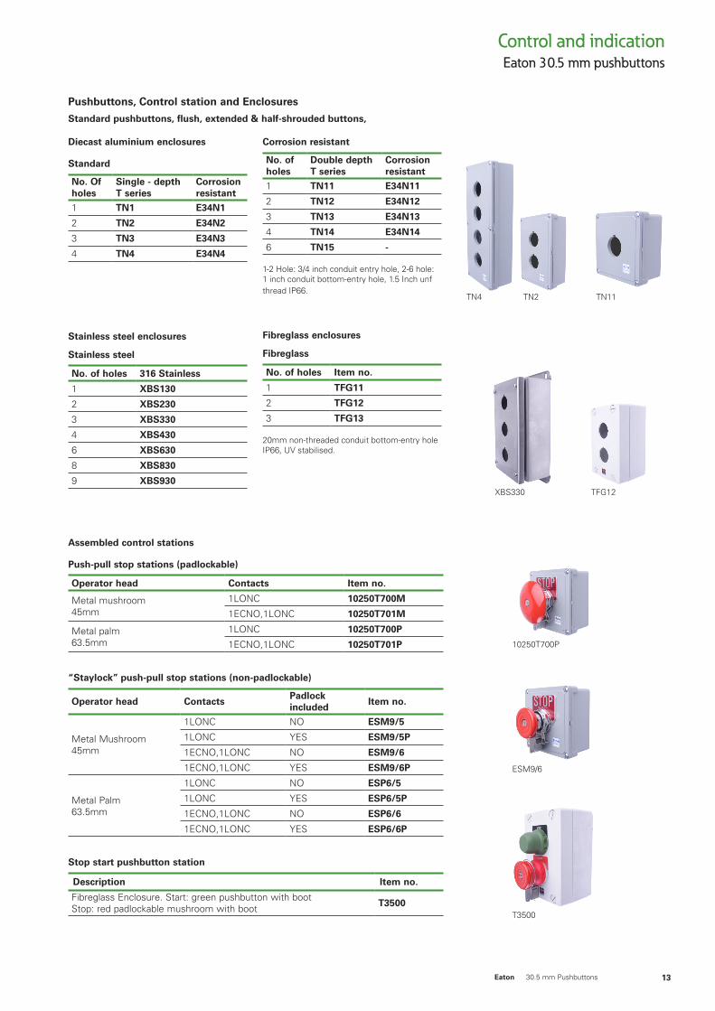
Pushbuttons, Control station and Enclosures
Standard pushbuttons, flush, extended & half-shrouded buttons,
Eaton 30.5 mm pushbuttonsControl and indication
13Eaton 30.5 mm Pushbuttons
Diecast aluminium enclosures
Standard
No. Of holes
Single - depth T series
Corrosion resistant
1 TN1 E34N1
2 TN2 E34N2
3 TN3 E34N3
4 TN4 E34N4
Stainless steel enclosures
Stainless steel
No. of holes 316 Stainless
1 XBS130
2 XBS230
3 XBS330
4 XBS430
6 XBS630
8 XBS830
9 XBS930
Corrosion resistant
No. of holes
Double depthT series
Corrosion resistant
1 TN11 E34N11
2 TN12 E34N12
3 TN13 E34N13
4 TN14 E34N14
6 TN15 -
1-2 Hole: 3/4 inch conduit entry hole, 2-6 hole: 1 inch conduit bottom-entry hole, 1.5 Inch unf thread IP66.
Fibreglass enclosures
Fibreglass
No. of holes Item no.
1 TFG11
2 TFG12
3 TFG13
20mm non-threaded conduit bottom-entry hole IP66, UV stabilised.
Assembled control stations
Push-pull stop stations (padlockable)
Operator head Contacts Item no.
Metal mushroom 45mm
1LONC 10250T700M
1ECNO,1LONC 10250T701M
Metal palm 63.5mm
1LONC 10250T700P
1ECNO,1LONC 10250T701P
“Staylock” push-pull stop stations (non-padlockable)
Operator head ContactsPadlock included
Item no.
Metal Mushroom 45mm
1LONC NO ESM9/5
1LONC YES ESM9/5P
1ECNO,1LONC NO ESM9/6
1ECNO,1LONC YES ESM9/6P
Metal Palm 63.5mm
1LONC NO ESP6/5
1LONC YES ESP6/5P
1ECNO,1LONC NO ESP6/6
1ECNO,1LONC YES ESP6/6P
Stop start pushbutton station
Description Item no.
Fibreglass Enclosure. Start: green pushbutton with bootStop: red padlockable mushroom with boot T3500
TN4
XBS330 TFG12
TN2 TN11
ESM9/6
10250T700P
T3500
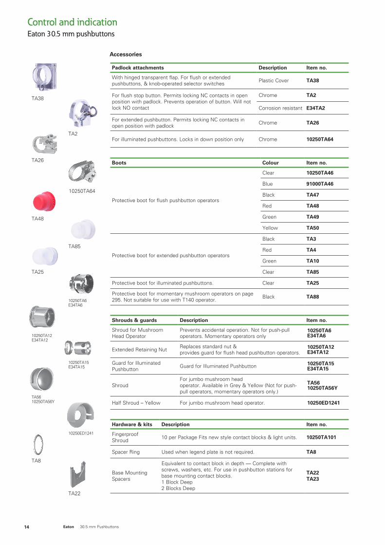
Accessories
Eaton 30.5 mm pushbuttonsControl and indication
14 Eaton 30.5 mm Pushbuttons
Padlock attachments Description Item no.
With hinged transparent flap. For flush or extended pushbuttons, & knob-operated selector switches Plastic Cover TA38
For flush stop button. Permits locking NC contacts in open position with padlock. Prevents operation of button. Will not lock NO contact
Chrome TA2
Corrosion resistant E34TA2
For extended pushbutton. Permits locking NC contacts in open position with padlock Chrome TA26
For illuminated pushbuttons. Locks in down position only Chrome 10250TA64
Boots Colour Item no.
Protective boot for flush pushbutton operators
Clear 10250TA46
Blue 91000TA46
Black TA47
Red TA48
Green TA49
Yellow TA50
Protective boot for extended pushbutton operators
Black TA3
Red TA4
Green TA10
Clear TA85
Protective boot for illuminated pushbuttons. Clear TA25
Protective boot for momentary mushroom operators on page 295. Not suitable for use with T140 operator. Black TA88
Shrouds & guards Description Item no.
Shroud for MushroomHead Operator
Prevents accidental operation. Not for push-pull operators. Momentary operators only
10250TA6E34TA6
Extended Retaining Nut Replaces standard nut &provides guard for flush head pushbutton operators.
10250TA12E34TA12
Guard for IlluminatedPushbutton Guard for Illuminated Pushbutton 10250TA15
E34TA15
ShroudFor jumbo mushroom head operator. Available in Grey & Yellow (Not for push-pull operators, momentary operators only.)
TA5610250TA56Y
Half Shroud – Yellow For jumbo mushroom head operator. 10250ED1241
Hardware & kits Description Item no.
Fingerproof Shroud 10 per Package Fits new style contact blocks & light units. 10250TA101
Spacer Ring Used when legend plate is not required. TA8
Base Mounting Spacers
Equivalent to contact block in depth — Complete with screws, washers, etc. For use in pushbutton stations for base mounting contact blocks.1 Block Deep2 Blocks Deep
TA22TA23
TA38
TA26
TA25
TA48
10250TA12 E34TA12
TA5610250TA56Y
TA8
TA2
TA85
10250TA64
10250TA6 E34TA6
10250TA15 E34TA15
10250ED1241
TA22
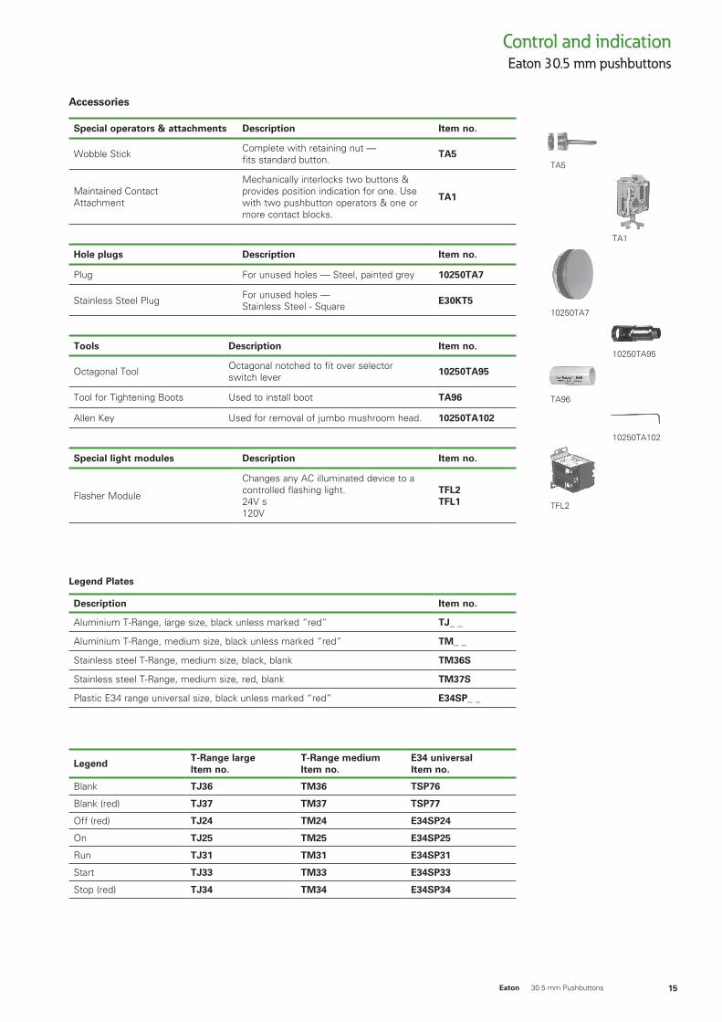
Accessories
Eaton 30.5 mm pushbuttonsControl and indication
15Eaton 30.5 mm Pushbuttons
Special operators & attachments Description Item no.
Wobble Stick Complete with retaining nut —fits standard button. TA5
Maintained ContactAttachment
Mechanically interlocks two buttons & provides position indication for one. Use with two pushbutton operators & one or more contact blocks.
TA1
Hole plugs Description Item no.
Plug For unused holes — Steel, painted grey 10250TA7
Stainless Steel Plug For unused holes — Stainless Steel - Square E30KT5
Tools Description Item no.
Octagonal Tool Octagonal notched to fit over selector switch lever 10250TA95
Tool for Tightening Boots Used to install boot TA96
Allen Key Used for removal of jumbo mushroom head. 10250TA102
Special light modules Description Item no.
Flasher Module
Changes any AC illuminated device to a controlled flashing light. 24V s120V
TFL2TFL1
Legend Plates
Description Item no.
Aluminium T-Range, large size, black unless marked “red” TJ_ _
Aluminium T-Range, medium size, black unless marked “red” TM_ _
Stainless steel T-Range, medium size, black, blank TM36S
Stainless steel T-Range, medium size, red, blank TM37S
Plastic E34 range universal size, black unless marked “red” E34SP_ _
LegendT-Range large Item no.
T-Range medium Item no.
E34 universal Item no.
Blank TJ36 TM36 TSP76
Blank (red) TJ37 TM37 TSP77
Off (red) TJ24 TM24 E34SP24
On TJ25 TM25 E34SP25
Run TJ31 TM31 E34SP31
Start TJ33 TM33 E34SP33
Stop (red) TJ34 TM34 E34SP34
TA5
10250TA7
TA96
TFL2
TA1
10250TA95
10250TA102
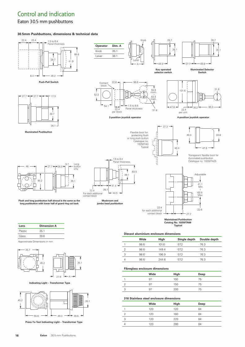
30.5mm Pushbuttons, dimensions & technical data
Eaton 30.5 mm pushbuttonsControl and indication
16 Eaton 30.5 mm Pushbuttons
Diecast aluminium enclosure dimensions
Wide High Single depth Double depth
1 98.6 101.6 57.2 76.3
2 98.6 149.4 57.2 76.3
3 98.6 196.9 57.2 76.3
4 98.6 244.6 57.2 76.3
Fibreglass enclosure dimensions
Wide High Deep
1 97 100 75
2 97 150 75
3 97 200 75
316 Stainless steel enclosure dimensions
Wide High Deep
1 120 120 84
2 120 160 84
3 120 220 84
4 120 280 84
47-161
Approximate Dimensions in mm
19.121.3
23.9
41.4 52.3
9.7
21.3 38.16.4
26.9
47.895.3
Lever Operator(For Use with Two VerticallyMounted Flush Pushbuttons)
Catalog No. 10250TA14
Padlock Attachmentfor Flush Pushbutton
Catalog No. 10250TA2
Padlock Attachmentfor Extended Pushbutton
Catalog No. 10250TA26
55.6 91.2
Cam
2-position joystick operator 4-position joystick operator
101.6
47.8 95.3
31.8
30.222.4
per unit
52.363.5main.
55.9mom.
54.1
31.8
98.622.6
22.4per block
1.5 to 6.6Panel thickness
Contactblock
Maintained PushbuttonCatalog No. 10250TA66
Typical
Flexible boot for protecting flush
or long push buttonCatalogue no.
10250TA3Typical 40.4
37.3
Transparent flexible boot for illuminated pushbuttonCatalogue no. 10250TA25
33.840.4
47.8
22.6
Adjustable
22.4for each additional
contact block 27.2
41.1Min.
63.5Max.
35.1
28.7
44.5
Key operatedselector switch
35.1
28.7
27.7 49.8
Illuminated SelectorSwitch
A
Lever
Knob
Operator Dim. A
Knob
Lever
35.1
38.1
24.6
41.4
Padlock Attachmentfor Knob Selector Switch
Catalog No. 10250TA11
Maintained ContactAttachment
Catalog No. 10250TA17 Typical
11.2
23.1
41.4Min.
58.7Max.
28.7
35.1
28.7
38.99.7Long
ButtonOnly
35.1
kcitS elbboWCatalog No. 10250TA5
Roto-Push
36.6
31
62
21°
21°
Press-To-Test Indicating Light – Resistor Type
epyT noeN dna rotsiseR – thgiL gnitacidnI
46
47.8
47.8 39.6
A27.9
48.5
Pushbutton withCylinder Lock
28.7
35.1
Flush and long pushbutton half shroud is the same as thelong pushbutton with lower half of guard ring cut back
46 27.7 26.99.7
35.145.2
Longbuttononly
Mushroom andjumbo head pushbutton
28.722.4For each additionalcontact block
44.5
41.4
38.163.5
1.5 to 6.4Panel thickness
Illuminated Pushbutton
27.7 27.7 17.5
28.7
35.1
Flush Pushbutton Operatorwith Padlock Attachment
51.6 50.827.7
28.7
45.2
45.2 35.1
45.2 35.1
Indicating Light – Transformer Type
45.7
45.2
A27.9
35.1
Jumbo Mushroom Head Pushbutton Operatorwith Padlock Attachment
63.5
58.7 60.5
44.5
Press-To-Test Indicating Light – Transformer Type
49.3 39.6
35.1
55.6
45.2
Mushroom Head Pushbutton Operatorwith Padlock Attachment
38.1
41.4
63.5 50.8
44.5
Push-Pull Switch
66.8
41.9
45.26.4
1.5 to 6.4Panel thickness
22.4 22.4
28.7
Approximate Dimensions in mm
Lens Dimension A
Plastic 35.1
Glass 39.6
30.5mm Pushbuttons, dimensions & technical data
Eaton 30.5 mm pushbuttonsControl and indication
17Eaton 30.5 mm Pushbuttons
47
41.9
Protecting Shroud forJumbo Mushroom Head Button
Catalog No. 10250TA56
82.6
44.5
38.1
21.3
Protecting Shroud forIlluminated PushbuttonCatalog No. 10250TA15
Protecting Shroud forMushroom Head ButtonCatalog No. 10250TA6
Padlock Hasp orFlip-Up Guard
Catalog No. TA38
38.938.1
44.542.9
9.7
Padlock Cover Guardfor Flush Pushbutton
Catalog No. 10250TA36
29.5 25.4
48.5
55.6
19.1
23.1
Padlock Attachmentfor Maintained Push-Pull Operator
Catalog No. 10250TA64
55.6
37.331.8
9.7
23.9
41.4
296 Mounting Holes
45.2 A
33.3
Master Test Module,Flasher Module
Legend Plate
B
A CD
Chain Hook Bracket
B E
9.7Dia. Hole
Approximate Dimensions in mm
Enclosure size(No. ofelements)
Dimensions in inches (mm)MountingWide
AHigh
BDeep
C D E
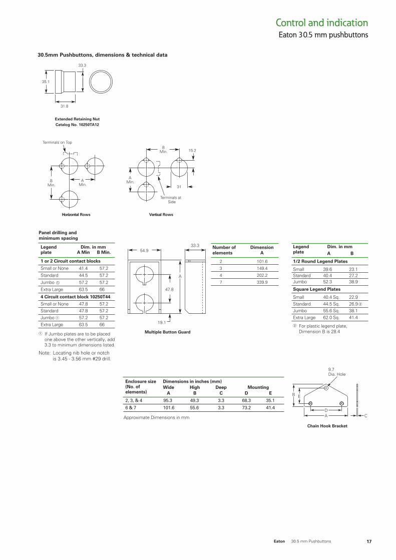
Panel drilling and minimum spacing
If Jumbo plates are to be placed one above the other vertically, add3.3 to minimum dimensions listed.
Note: Locating nib hole or notch is 3.45 - 3.56 mm #29 drill.
Legendplate
Dim. in mmA Min
1 or 2 Circuit contact blocks
4 Circuit contact block 10250T44
Small or None 41.4 57.2
Standard 44.5 57.2
Jumbo 57.2 57.2
Extra Large 63.5 66
Small or None 47.8 57.2Standard 47.8 57.2Jumbo 57.2 57.2Extra Large 63.5 66
B Min.
For plastic legend plate, Dimension B is 28.4
1/2 Round Legend Plates
Square Legend Plates
Legendplate
Small 39.6 23.1Standard 40.4 27.2Jumbo 52.3 38.9
Small 40.4 Sq. 22.9Standard 44.5 Sq. 26.9 Jumbo 55.6 Sq. 38.1Extra Large 62.0 Sq. 41.4
Dim. in mmA B
Number ofelements
DimensionA
2 101.6
3 149.4
4 202.2
7 339.9
54.933.3
47.8
19.1
Multiple Button Guard
A
BMin.
AMin.
Terminals on Top
AMin.
15.2
31
BMin.
Terminals atSide
Horizontal Rows Vertical Rows
Extended Retaining NutCatalog No. 10250TA12
35.1
33.3
31.8
Control and indication
18 Eaton 30.5 mm Pushbuttons
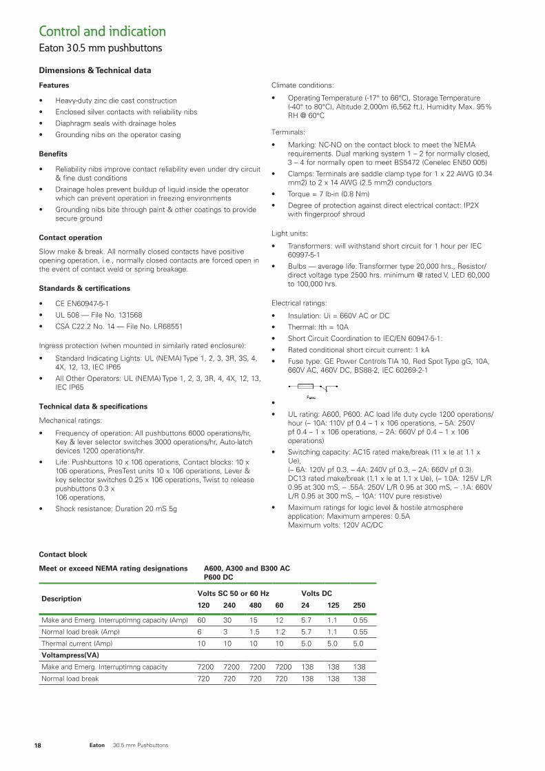
Features
• Heavy-duty zinc die cast construction
• Enclosed silver contacts with reliability nibs
• Diaphragm seals with drainage holes
• Grounding nibs on the operator casing
Benefits
• Reliability nibs improve contact reliability even under dry circuit & fine dust conditions
• Drainage holes prevent buildup of liquid inside the operator which can prevent operation in freezing environments
• Grounding nibs bite through paint & other coatings to provide secure ground
Contact operation
Slow make & break. All normally closed contacts have positive opening operation, i.e., normally closed contacts are forced open in the event of contact weld or spring breakage.
Standards & certifications
• CE EN60947-5-1
• UL 508 — File No. 131568
• CSA C22.2 No. 14 — File No. LR68551
Ingress protection (when mounted in similarly rated enclosure):
• Standard Indicating Lights: UL (NEMA) Type 1, 2, 3, 3R, 3S, 4, 4X, 12, 13, IEC IP65
• All Other Operators: UL (NEMA) Type 1, 2, 3, 3R, 4, 4X, 12, 13, IEC IP65
Technical data & specifications
Mechanical ratings:
• Frequency of operation: All pushbuttons 6000 operations/hr, Key & lever selector switches 3000 operations/hr, Auto-latch devices 1200 operations/hr.
• Life: Pushbuttons 10 x 106 operations, Contact blocks: 10 x 106 operations, PresTest units 10 x 106 operations, Lever & key selector switches 0.25 x 10⁶ operations, Twist to release pushbuttons 0.3 x 10⁶ operations,
• Shock resistance: Duration 20 mS 5g
Climate conditions:
• Operating Temperature (-17° to 66°C), Storage Temperature (-40° to 80°C), Altitude 2,000m (6,562 ft.), Humidity Max. 95% RH @ 60°C
Terminals:
• Marking: NC-NO on the contact block to meet the NEMA requirements. Dual marking system 1 – 2 for normally closed, 3 – 4 for normally open to meet BS5472 (Cenelec EN50 005)
• Clamps: Terminals are saddle clamp type for 1 x 22 AWG (0.34 mm2) to 2 x 14 AWG (2.5 mm2) conductors
• Torque = 7 lb-in (0.8 Nm)
• Degree of protection against direct electrical contact: IP2X with fingerproof shroud
Light units:
• Transformers: will withstand short circuit for 1 hour per IEC 60997-5-1
• Bulbs — average life: Transformer type 20,000 hrs., Resistor/direct voltage type 2500 hrs. minimum @ rated V, LED 60,000 to 100,000 hrs.
Electrical ratings:
• Insulation: Ui = 660V AC or DC
• Thermal: lth = 10A
• Short Circuit Coordination to IEC/EN 60947-5-1:
• Rated conditional short circuit current: 1 kA
• Fuse type: GE Power Controls TIA 10, Red Spot Type gG, 10A, 660V AC, 460V DC, BS88-2, IEC 60269-2-1
•
• UL rating: A600, P600: AC load life duty cycle 1200 operations/hour (– 10A: 110V pf 0.4 – 1 x 10⁶ operations, – 5A: 250V pf 0.4 – 1 x 10⁶ operations, – 2A: 660V pf 0.4 – 1 x 10⁶ operations)
• Switching capacity: AC15 rated make/break (11 x le at 1.1 x Ue), (– 6A: 120V pf 0.3, – 4A: 240V pf 0.3, – 2A: 660V pf 0.3). DC13 rated make/break (1.1 x le at 1.1 x Ue), (– 1.0A: 125V L/R 0.95 at 300 mS, – .55A: 250V L/R 0.95 at 300 mS, – .1A: 660V L/R 0.95 at 300 mS, – 10A: 110V pure resistive)
• Maximum ratings for logic level & hostile atmosphere application: Maximum amperes: 0.5A Maximum volts: 120V AC/DC
Contact block
Meet or exceed NEMA rating designations A600, A300 and B300 AC P600 DC
DescriptionVolts SC 50 or 60 Hz Volts DC
120 240 480 60 24 125 250
Make and Emerg. Interruptimng capacity (Amp) 60 30 15 12 5.7 1.1 0.55
Normal load break (Amp) 6 3 1.5 1.2 5.7 1.1 0.55
Thermal current (Amp) 10 10 10 10 5.0 5.0 5.0
Voltampress(VA)
Make and Emerg. Interruptimng capacity 7200 7200 7200 7200 138 138 138
Normal load break 720 720 720 720 138 138 138
Dimensions & Technical data
Eaton 30.5 mm pushbuttons
Eaton’s electrical business is a global leader with expertise in power distribution and circuit protection; backup power protection; control and automation; lighting and security; structural solutions and wiring devices; solutions for harsh and hazardous environments; and engineering services. Eaton is positioned through its global solutions to answer today’s most critical electrical power management challenges.
Eaton is a power management company with 2016 sales of $19.7 billion. Eaton provides energy efficient solutions that help our customers effectively manage electrical, hydraulic and mechanical power more efficiently, safely and sustainably. Eaton has approximately 95,000 employees and sells products to customers in more than 175 countries.
For more information, visit www.eaton.com.
EatonEaton Industries Pty Ltd ABN 66 103 014 57110 Kent RoadMascot NSW 20201300 3 EATONEatoncorp.com.au
© 2017 EatonAll Rights ReservedPrinted in AustraliaAugust 2017
Eaton is a registered trademark.
All other trademarks are property of their respective owners.