logic control section 10 - usesi careers
TRANSCRIPT
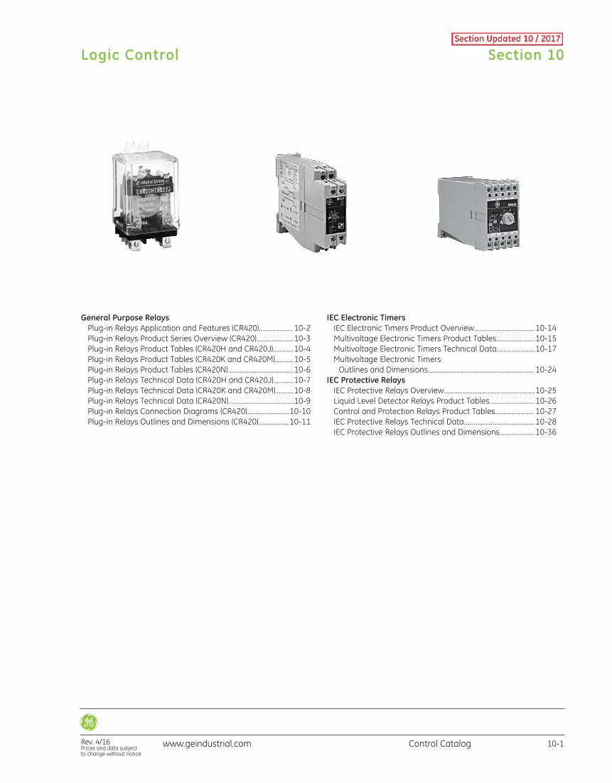
General Purpose RelaysPlug-in Relays Application and Features (CR420).................... 10-2Plug-in Relays Product Series Overview (CR420)......................10-3Plug-in Relays Product Tables (CR420H and CR420J)............10-4Plug-in Relays Product Tables (CR420K and CR420M)...........10-5Plug-in Relays Product Tables (CR420N).......................................10-6Plug-in Relays Technical Data (CR420H and CR420J)............10-7Plug-in Relays Technical Data (CR420K and CR420M)...........10-8Plug-in Relays Technical Data (CR420N).......................................10-9Plug-in Relays Connection Diagrams (CR420).........................10-10Plug-in Relays Outlines and Dimensions (CR420)..................10-11
IEC Electronic TimersIEC Electronic Timers Product Overview....................................10-14Multivoltage Electronic Timers Product Tables.......................10-15Multivoltage Electronic Timers Technical Data.......................10-17Multivoltage Electronic Timers Outlines and Dimensions............................................................... 10-24
IEC Protective RelaysIEC Protective Relays Overview......................................................10-25Liquid Level Detector Relays Product Tables...........................10-26Control and Protection Relays Product Tables....................... 10-27IEC Protective Relays Technical Data..........................................10-28IEC Protective Relays Outlines and Dimensions.....................10-36
Section 10
Rev. 4/16Prices and data subject to change without notice
Logic Control
10-1Control Catalogwww.geindustrial.com
CR420Plug-In Relays
Application
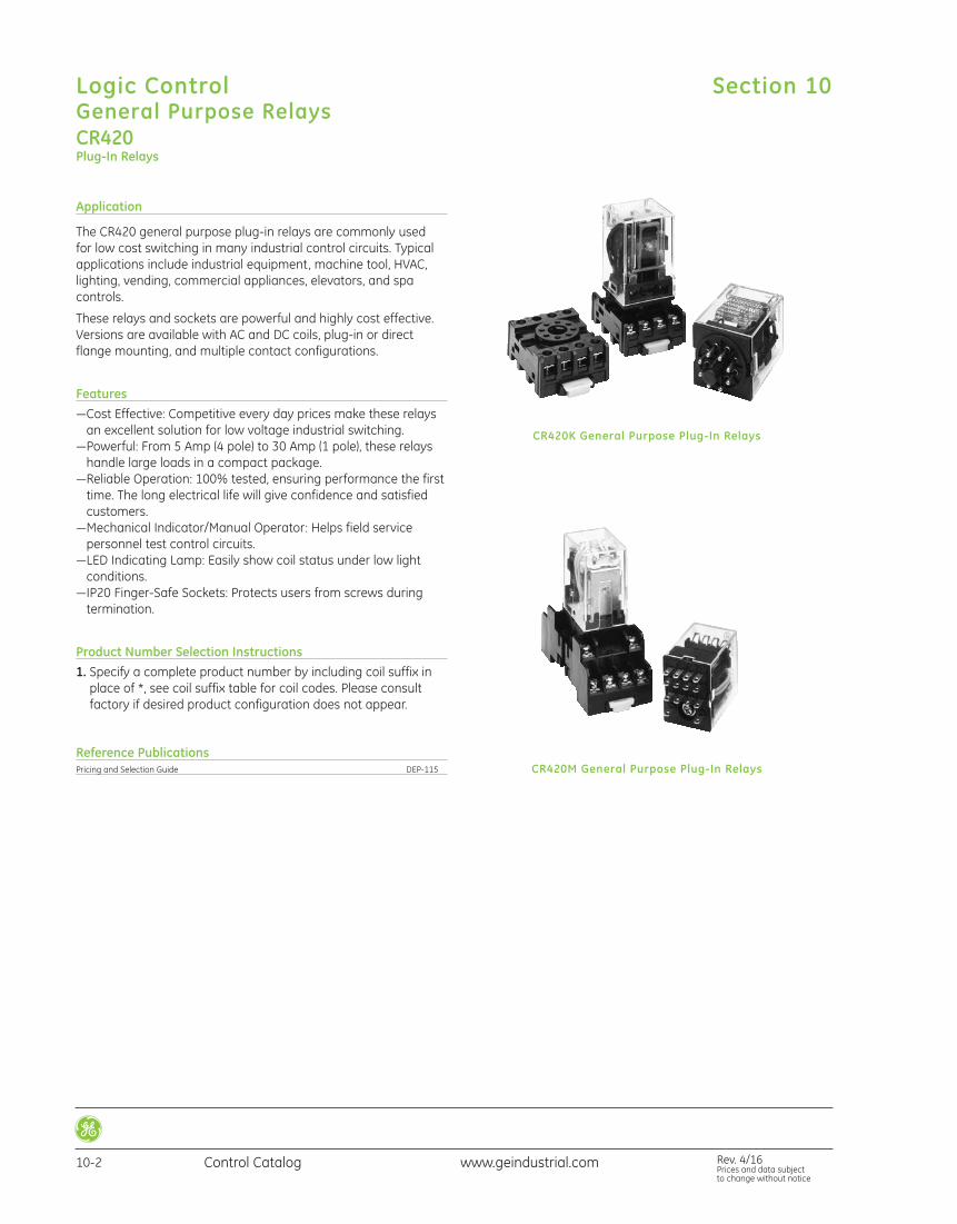
The CR420 general purpose plug-in relays are commonly used for low cost switching in many industrial control circuits. Typicalapplications include industrial equipment, machine tool, HVAC,lighting, vending, commercial appliances, elevators, and spa controls.
These relays and sockets are powerful and highly cost effective.Versions are available with AC and DC coils, plug-in or directflange mounting, and multiple contact configurations.
Features—Cost Effective: Competitive every day prices make these relaysan excellent solution for low voltage industrial switching.
—Powerful: From 5 Amp (4 pole) to 30 Amp (1 pole), these relayshandle large loads in a compact package.
—Reliable Operation: 100% tested, ensuring performance the firsttime. The long electrical life will give confidence and satisfied customers.
—Mechanical Indicator/Manual Operator: Helps field service personnel test control circuits.
—LED Indicating Lamp: Easily show coil status under low light conditions.
—IP20 Finger-Safe Sockets: Protects users from screws during ter mination.
Product Number Selection Instructions1. Specify a complete product number by including coil suffix in
place of *, see coil suffix table for coil codes. Please consult factory if desired product configuration does not appear.
Reference PublicationsPricing and Selection Guide DEP-115
CR420K General Purpose Plug-In Relays
CR420M General Purpose Plug-In Relays
Section 10Logic ControlGeneral Purpose Relays
10-2 Control Catalog Rev. 4/16Prices and data subject to change without notice
www.geindustrial.com
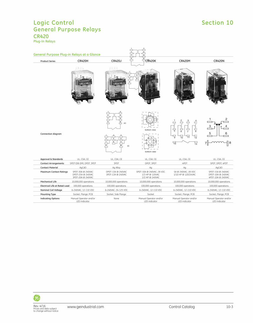
General Purpose Plug-in Relays at a Glance
Product Series CR420H CR420J CR420K CR420M CR420N
Connection diagram
Approval & Standards UL, CSA, CE UL, CSA, CE UL, CSA, CE UL, CSA, CE UL, CSA, CE
Contact Arrangements SPDT (DB-DM), DPDT, 3PDT 3PDT DPDT, 3PDT 4PDT SPDT, DPDT, 4PDT
Contact Material AgCdO Ag Alloy Ag Ag AgCdO
Maximum Contact Ratings SPDT-30A @ 240VAC DPDT-13A @ 240VAC SPDT-10A @ 240VAC, 28 VDC 5A @ 240VAC, 28 VDC SPDT-15A @ 240VAC DPDT-25A @ 240VAC 3PDT-13A @ 240VAC 1/3 HP @ 120VAC 1/10 HP @ 120/24VAC DPDT-10A @ 240VAC 3PDT-20A @ 240VAC 1/2 HP @ 240VAC 4PDT-10A @ 240VAC
Mechanical Life 10,000,000 operations 10,000,000 operations 10,000,000 operations 10,000,000 operations 10,000,000 operations
Electrical Life at Rated Load 100,000 operations 100,000 operations 100,000 operations 100,000 operations 100,000 operations
Nominal Coil Voltage 6-240VAC, 12-110 VDC 6-240VAC, 24-125 VDC 6-240VAC, 12-110 VDC 6-240VAC, 12-110 VDC 6-240VAC, 12-110 VDC
Mounting Type Socket, Flange, PCB Socket, Side Flange Socket Socket, Flange, PCB Socket, Flange, PCB
Indicating Options Manual Operator and/or None Manual Operator and/or Manual Operator and/or Manual Operator and/or LED indicator LED indicator LED indicator LED indicator
CR420Plug-In Relays
Section 10
Rev. 4/16Prices and data subject to change without notice
Logic ControlGeneral Purpose Relays
10-3Control Catalogwww.geindustrial.com
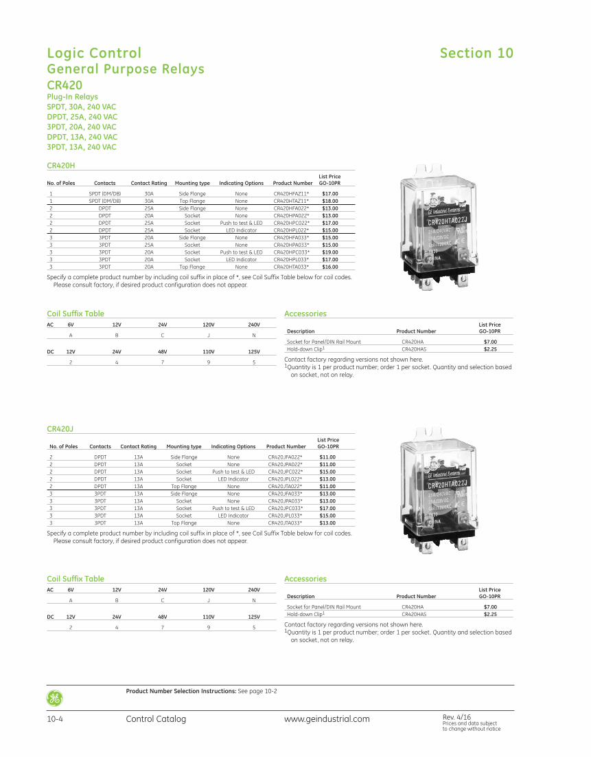
CR420Plug-In RelaysSPDT, 30A, 240 VACDPDT, 25A, 240 VAC3PDT, 20A, 240 VACDPDT, 13A, 240 VAC3PDT, 13A, 240 VAC
Coil Suffix TableAC 6V 12V 24V 120V 240V
A B C J N
DC 12V 24V 48V 110V 125V
2 4 7 9 5
Accessories List Price Description Product Number GO-10PR
Socket for Panel/DIN Rail Mount CR420HA $7.00 Hold-down Clip1 CR420HAS $2.25
Contact factory regarding versions not shown here.1Quantity is 1 per product number; order 1 per socket. Quantity and selection based
on socket, not on relay.
Coil Suffix TableAC 6V 12V 24V 120V 240V
A B C J N
DC 12V 24V 48V 110V 125V
2 4 7 9 5
CR420H List PriceNo. of Poles Contacts Contact Rating Mounting type Indicating Options Product Number GO-10PR
1 SPDT (DM/DB) 30A Side Flange None CR420HFAZ11* $17.00 1 SPDT (DM/DB) 30A Top Flange None CR420HTAZ11* $18.00 2 DPDT 25A Side Flange None CR420HFA022* $13.00 2 DPDT 20A Socket None CR420HPA022* $13.00 2 DPDT 25A Socket Push to test & LED CR420HPC022* $17.00 2 DPDT 25A Socket LED Indicator CR420HPL022* $15.00 3 3PDT 20A Side Flange None CR420HFA033* $15.00 3 3PDT 25A Socket None CR420HPA033* $15.00 3 3PDT 20A Socket Push to test & LED CR420HPC033* $19.00 3 3PDT 20A Socket LED Indicator CR420HPL033* $17.00 3 3PDT 20A Top Flange None CR420HTA033* $16.00
Specify a complete product number by including coil suffix in place of *, see Coil Suffix Table below for coil codes.Please consult factory, if desired product configuration does not appear.
CR420J List Price No. of Poles Contacts Contact Rating Mounting type Indicating Options Product Number GO-10PR
2 DPDT 13A Side Flange None CR420JFA022* $11.00 2 DPDT 13A Socket None CR420JPA022* $11.00 2 DPDT 13A Socket Push to test & LED CR420JPC022* $15.00 2 DPDT 13A Socket LED Indicator CR420JPL022* $13.00 2 DPDT 13A Top Flange None CR420JTA022* $11.00 3 3PDT 13A Side Flange None CR420JFA033* $13.00 3 3PDT 13A Socket None CR420JPA033* $13.00 3 3PDT 13A Socket Push to test & LED CR420JPC033* $17.00 3 3PDT 13A Socket LED Indicator CR420JPL033* $15.00 3 3PDT 13A Top Flange None CR420JTA033* $13.00
Specify a complete product number by including coil suffix in place of *, see Coil Suffix Table below for coil codes.Please consult factory, if desired product configuration does not appear.
Accessories List Price Description Product Number GO-10PR
Socket for Panel/DIN Rail Mount CR420HA $7.00 Hold-down Clip1 CR420HAS $2.25
Contact factory regarding versions not shown here.1Quantity is 1 per product number; order 1 per socket. Quantity and selection based
on socket, not on relay.
Section 10Logic ControlGeneral Purpose Relays
10-4 Control Catalog Rev. 4/16Prices and data subject to change without notice
www.geindustrial.com
Product Number Selection Instructions: See page 10-2
Coil Suffix TableAC 6V 12V 24V 120V 240V
A B C J N
DC 12V 24V 48V 110V 125V
2 4 7 9 5
Coil Suffix TableAC 6V 12V 24V 120V 240V
A B C J N
DC 12V 24V 48V 110V 125V
2 4 7 9 5
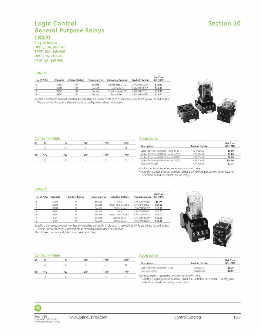
CR420K List Price No. of Poles Contacts Contact Rating Mounting type Indicating Options Product Number GO-10PR
2 DPDT 10A Socket Push to test & LED CR420KPC022* $12.00 2 DPDT 10A Socket Push to Test CR420KPM022* $10.00 3 3PDT 10A Socket Push to test & LED CR420KPC033* $16.00 3 3PDT 10A Socket Push to Test CR420KPM033* $14.00
Specify a complete product number by including coil suffix in place of *, see Coil Suffix Table below for coil codes.Please consult factory, if desired product configuration does not appear.
Accessories List Price Description Product Number GO-10PR
Socket for Panel/DIN Rail Mount (DPDT) CR420KA2 $5.00 Socket for Panel/DIN Rail Mount (3PDT) CR420KA3 $7.00 Socket for Panel/DIN Rail Mount (DPDT) CR420KA21 $8.00 Socket for Panel/DIN Rail Mount (3PDT) CR420KA31 $10.00 Hold-down Clips2 CR420KAS $2.25
Contact factory regarding versions not shown here.2Quantity is 2 per product number; order 1 CR420KAS per socket. Quantity and
selection based on socket, not on relay.
CR420Plug-In RelaysDPDT, 10A, 240 VAC3PDT, 10A, 240 VACDPDT, 5A, 240 VAC4PDT, 5A, 240 VAC
CR420M List Price No. of Poles Contacts Contact Rating Mounting type Indicating Options Product Number GO-10PR
2 DPDT 5A Socket None CR420MPA022* $8.00 2 DPDT 5A Socket Push to test & LED CR420MPC022* $14.00 2 DPDT 5A Socket LED Indicator CR420MPL022* $10.00 4 4PDT 5A Socket None CR420MPA044* $10.00 4 4PDT 5A Socket Push to test & LED CR420MPC044* $14.00 4 4PDT 5A Socket LED Indicator CR420MPL044* $12.00 4 4PDT 5A1 Socket LED Indicator CR420MPLG44* $17.00
Specify a complete product number by including coil suffix in place of *, see Coil Suffix Table below for coil codes.Please consult factory, if desired product configuration does not appear.
1Au diffused contact suitable for low level switching.
Accessories List Price Description Product Number GO-10PR
Socket for Panel/DIN Rail Mount CR420MA $8.00 Hold-down Clips2 CR420MAS $2.25
Contact factory regarding versions not shown here.2Quantity is 2 per product number; order 1 CR420MAS per socket. Quantity and
selection based on socket, not on relay.
Section 10
Rev. 4/16Prices and data subject to change without notice
Logic ControlGeneral Purpose Relays
10-5Control Catalogwww.geindustrial.com
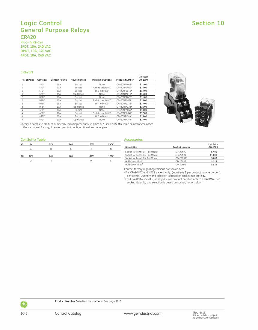
CR420N List Price No. of Poles Contacts Contact Rating Mounting type Indicating Options Product Number GO-10PR
1 SPDT 15A Socket None CR420NPA011* $11.00 1 SPDT 10A Socket Push to test & LED CR420NPC011* $15.00 1 SPDT 10A Socket LED Indicator CR420NPL011* $13.00 1 SPDT 15A Top Flange None CR420NTA011* $11.00 2 DPDT 10A Socket None CR420NPA022* $11.00 2 DPDT 10A Socket Push to test & LED CR420NPC022* $15.00 2 DPDT 15A Socket LED Indicator CR420NPL022* $13.00 2 DPDT 10A Top Flange None CR420NTA022* $11.00 4 4PDT 10A Socket None CR420NPA044* $13.00 4 4PDT 10A Socket Push to test & LED CR420NPC044* $17.00 4 4PDT 10A Socket LED Indicator CR420NPL044* $15.00 4 4PDT 10A Top Flange None CR420NTA044* $13.00
Specify a complete product number by including coil suffix in place of *, see Coil Suffix Table below for coil codes.Please consult factory, if desired product configuration does not appear.
CR420Plug-In RelaysSPDT, 15A, 240 VACDPDT, 10A, 240 VAC4PDT, 10A, 240 VAC
Accessories List Price Description Product Number GO-10PR
Socket for Panel/DIN Rail Mount CR420NA2 $7.00 Socket for Panel/DIN Rail Mount CR420NA4 $10.00 Socket for Panel/DIN Rail Mount CR420NA21 $8.00 Hold-down Clip1 CR420NAS $2.25 Hold-down Clips2 CR420MAS $2.25
Contact factory regarding versions not shown here.1Fits CR420NA2 and NA21 sockets only. Quantity is 1 per product number; order 1
per socket. Quantity and selection is based on socket, not on relay.2Fits CR420NA4 socket. Quantity is 2 per product number; order 1 CR420MAS per
socket. Quantity and selection is based on socket, not on relay.
Coil Suffix TableAC 6V 12V 24V 120V 240V
A B C J N
DC 12V 24V 48V 110V 125V
2 4 7 9 5
Section 10Logic ControlGeneral Purpose Relays
10-6 Control Catalog Rev. 4/16Prices and data subject to change without notice
www.geindustrial.com
Product Number Selection Instructions: See page 10-2
CR420Plug-In RelaysTechnical Data
CR420H Contact Data Contact Ratings SPDT (DM/DB): 30A @ 240VAC, 28VDC 1 HP @ 120VAC 1 1/2 HP @ 240VAC
DPDT: 25A @ 240VAC, 28VDC 3/4 HP @ 120VAC 1 HP @ 240VAC
3PDT: 20A @ 240VAC, 28VDC 3/4 HP @ 120VAC 1 HP @ 240VAC
Contact Material Ag Alloy
Maximum Contact Voltage 220VAC, 110VDC
Carry Current 10A
Electrical Life 100,000 operations
Mechanical Life 10,000,000 operations
Minimum Permissible Load 0.5A @ 1VDC
CR420J Contact Data Contact Ratings 13A @ 240VAC
Contact Material Ag Alloy
Maximum Contact Voltage 24 VDC 24VAC 120 VAC
Carry Current 10A
Electrical Life 100,000 operations
Mechanical Life 10,000,000 operations
Minimum Permissible Load 0.5A @ 5VDC
CR420H General Technical Information Contact Resistance 50m ohms Maximum
Operating Time 25mS Maximum
Release Time 25mS Maximum
Insulation Resistance 100m ohms Minimum @ 500 VDC
Electrical Switching Rate 30 Operations/Minute
Mechanical Switching Rate 240 Operations/Minute
Dielectric Strength Between Coil & Contacts 1500VAC for One Minute
Dielectric Strength Between Contacts 750VAC for One Minute
Mechanical Vibration 100G Minimum
Malfunction Vibration 10G Minimum
Operating Temperature -10° to 60°C
Humidity 35-85% RH
Weight Approx. 85 g
CR420J General Technical Information Contact Resistance 100m ohms Maximum
Operating Time 25mS Maximum
Release Time 25mS Maximum
Insulation Resistance 1,000 Mohm
Electrical Switching Rate 30 Operations/Minute
Mechanical Switching Rate 240 Operations/Minute
Dielectric Strength Between Coil & Contacts 1500VAC for One Minute
Dielectric Strength Between Contacts 750VAC for One Minute
Mechanical Vibration 100G Minimum
Malfunction Vibration 20G Minimum
Operating Temperature -25° to 60°C
Humidity 35-85% RH
Weight Approx. 85 g
CR420H Coil Data @ 20°C AC Coil Power Consumption 2.3VA @ 50/60 Hz
DC Coil Power Consumption 1.5W
Coil Pick-Up Voltage 80% Nominal Maximum
AC Coil Drop-Out Voltage 30% Nominal Minimum
DC Coil Drop-Out Voltage 10% Nominal Minimum
Maximum Coil Voltage 110% Nominal Maximum
CR420J Coil Data @ 20°C AC Coil Power Consumption 2.3VA @ 50/60 Hz
DC Coil Power Consumption
Coil Pick-Up Voltage AC 85% Nominal Maximum DC 75% Nominal Maximum
AC Coil Drop-Out Voltage 30% Nominal Minimum
DC Coil Drop-Out Voltage 10% Nominal Minimum
Maximum Coil Voltage 110% Nominal Maximum
Section 10
Rev. 4/16Prices and data subject to change without notice
Logic ControlGeneral Purpose Relays
10-7Control Catalogwww.geindustrial.com
CR420Plug-In RelaysTechnical Data
CR420K Contact Data Contact Ratings DPDT/3PDT: 10A res. @ 240VAC, 24VDC 7A Ind. (p.f.=0.4), 250VAC 1/2 HP @ 120VAC, 1/3 HP @ 240VAC
Contact Material Ag Alloy
Maximum Contact Voltage 220VAC, 110VDC
Carry Current 10A
Electrical Life 100,000 operations
Mechanical Life 10,000,000 operations
Minimum Permissible Load 100mA @ 5VDC
CR420K Coil Data @ 20°C AC Coil Power Consumption 2.3VA @ 50/60 Hz
DC Coil Power Consumption 1.5W
Coil Pick-Up Voltage 80% Nominal Maximum
AC Coil Drop-Out Voltage 30% Nominal Minimum
DC Coil Drop-Out Voltage 10% Nominal Minimum
Maximum Coil Voltage 110% Nominal Maximum
CR420K General Technical Information Contact Resistance 100m ohms Maximum
Operating Time 25mS Maximum
Release Time 25mS Maximum
Insulation Resistance 100m ohms Minimum @ 500VDC
Electrical Switching Rate 30 Operations/Minute
Mechanical Switching Rate 240 Operations/Minute
Dielectric Strength Between Coil & Contacts 1500VAC @ 50/60 Hz
Dielectric Strength Between Contacts 1000VAC @ 50/60 Hz
Mechanical Vibration 100G Minimum
Malfunction Vibration 10G Minimum
Operating Temperature -10° to 40°C
Humidity 35-85% RH
Weight Approx. 85 g
CR420M Contact Data Contact Ratings 4PDT: 5A @ 240VAC, 24VDC 1/10 HP @ 120/240VAC
Contact Material Ag Alloy
Maximum Contact Voltage 220VAC, 110VDC
Carry Current 5A
Electrical Life 100,000 operations
Mechanical Life 10,000,000 operations
Minimum Permissible Load SPDT/4PDT: 10mA @ 24VDC
4PDT (Ag with AU diffused): 10mA @ 24VDC
CR420M Coil Data @ 20°C AC Coil Power Consumption 1.1VA @ 50/60 Hz
DC Coil Power Consumption 0.9W
Coil Pick-Up Voltage AC 85% Nominal Maximum DC 75% Nominal Maximum
AC Coil Drop-Out Voltage 30% Nominal Minimum
DC Coil Drop-Out Voltage 10% Nominal Minimum
Maximum Coil Voltage 110% Nominal Maximum
CR420M General Technical Information Contact Resistance 100m ohms Maximum
Operating Time 25mS Maximum
Release Time 25mS Maximum
Insulation Resistance 100m ohms Minimum @ 500VDC
Electrical Switching Rate 30 Operations/Minute
Mechanical Switching Rate 240 Operations/Minute
Dielectric Strength Between Coil & Contacts 1500VAC @ 50/60 Hz
Dielectric Strength Between Contacts 1000VAC @ 50/60 Hz
Mechanical Vibration 100G Minimum
Malfunction Vibration 10G Minimum
Operating Temperature -25° to 70°C
Humidity 35-85% RH
Weight Approx. 35 g
Section 10Logic ControlGeneral Purpose Relays
10-8 Control Catalog Rev. 4/16Prices and data subject to change without notice
www.geindustrial.com
Product Number Selection Instructions: See page 10-2
CR420Plug-In RelaysTechnical Data
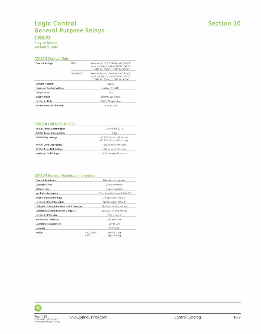
CR420N Contact Data Contact Ratings SPDT: Resistive (p.f.=1.0) 15A@240VAC, 24VDC Inductive (p.f.=0.4) 7A@240VAC, 24VDC 1/3 HP @ 120VAC, 1/2 HP @ 240VAC
DPDT/4PDT: Resistive (p.f.=1.0) 10A@240VAC, 24VDC Inductive (p.f.=0.4) 5A@240VAC, 24VDC 1/3 HP @ 120VAC, 1/2 HP @ 240VAC
Contact Material AgCdO
Maximum Contact Voltage 240VAC, 110VDC
Carry Current 10A
Electrical Life 100,000 operations
Mechanical Life 10,000,000 operations
Minimum Permissible Load 10mA @ 5VDC
CR420N Coil Data @ 20°C AC Coil Power Consumption 1.1VA @ 50/60 Hz
DC Coil Power Consumption 0.9W
Coil Pick-Up Voltage AC 85% Nominal Maximum DC 75% Nominal Maximum
AC Coil Drop-Out Voltage 30% Nominal Minimum
DC Coil Drop-Out Voltage 10% Nominal Minimum
Maximum Coil Voltage 110% Nominal Maximum
CR420N General Technical Information Contact Resistance 100m ohms Maximum
Operating Time 25mS Maximum
Release Time 25mS Maximum
Insulation Resistance 100m ohms Minimum @ 500VDC
Electrical Switching Rate 30 Operations/Minute
Mechanical Switching Rate 240 Operations/Minute
Dielectric Strength Between Coil & Contacts 1500VAC for One Minute
Dielectric Strength Between Contacts 1000VAC for One Minute
Mechanical Vibration 100G Minimum
Malfunction Vibration 10G Minimum
Operating Temperature -25° to 60°C
Humidity 35-85% RH
Weight SPDT/DPDT: Approx. 35 g 4PDT: Approx. 85 g
Section 10
Rev. 4/16Prices and data subject to change without notice
Logic ControlGeneral Purpose Relays
10-9Control Catalogwww.geindustrial.com
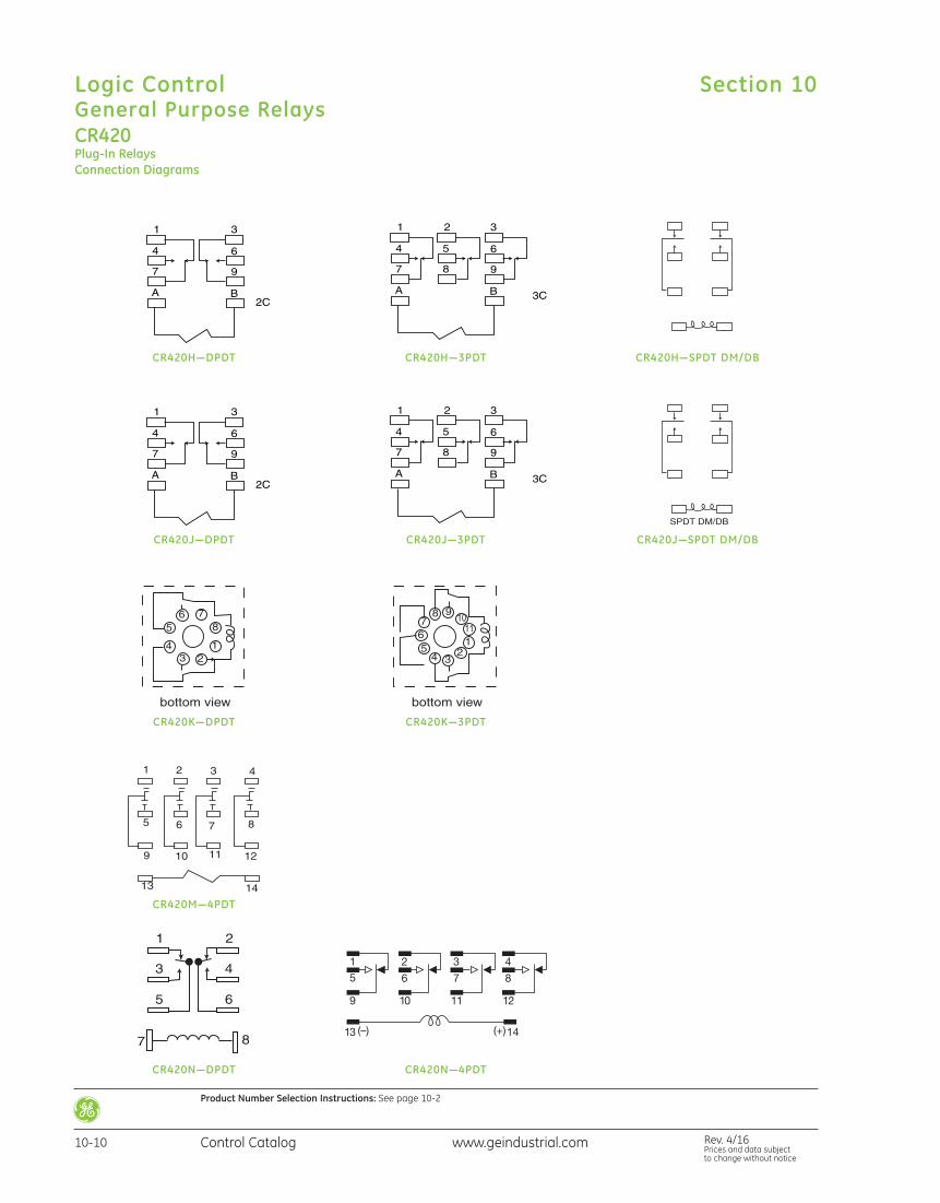
CR420Plug-In RelaysConnection Diagrams
1
5
9
2
6
10
13 (–) (+) 14
3
7
11
4
8
12
CR420J—DPDT
CR420K—DPDT
CR420M—4PDT
CR420N—DPDT CR420N—4PDT
CR420K—3PDT
CR420J—3PDT CR420J—SPDT DM/DB
CR420H—3PDTCR420H—DPDT CR420H—SPDT DM/DB
Section 10Logic ControlGeneral Purpose Relays
10-10 Control Catalog Rev. 4/16Prices and data subject to change without notice
www.geindustrial.com
Product Number Selection Instructions: See page 10-2
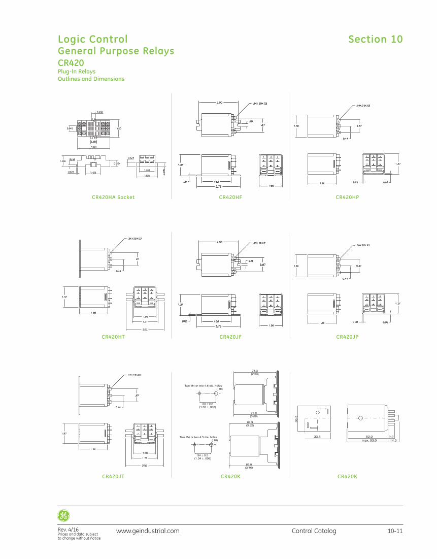
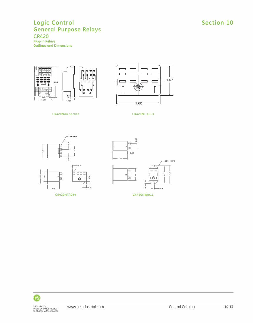
CR420Plug-In RelaysOutlines and Dimensions
CR420HA Socket
CR420HT
CR420JT
CR420HF
CR420JF
CR420K
CR420HP
CR420JP
CR420K
Section 10
Rev. 4/16Prices and data subject to change without notice
Logic ControlGeneral Purpose Relays
10-11Control Catalogwww.geindustrial.com
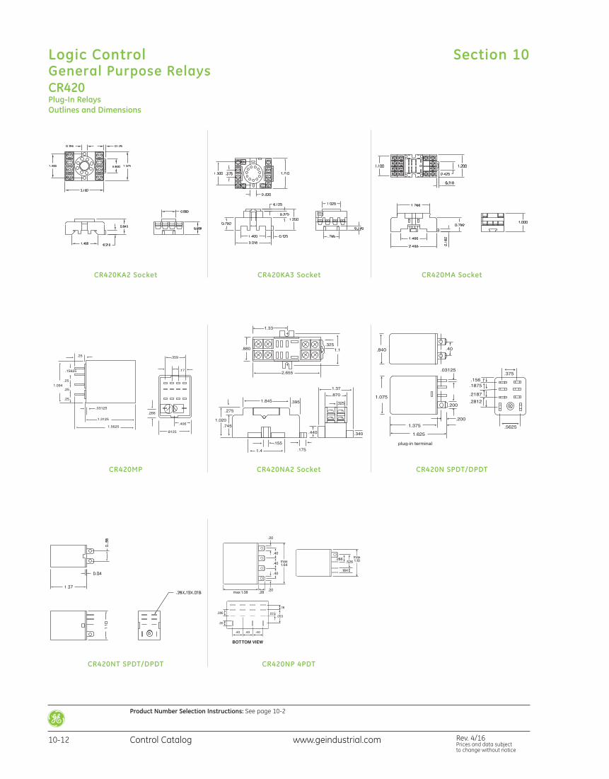
CR420Plug-In RelaysOutlines and Dimensions
CR420KA2 Socket
CR420NA2 Socket
CR420KA3 Socket
CR420MP CR420N SPDT/DPDT
CR420MA Socket
CR420NT SPDT/DPDT
.286 .02.053
.18
.20
.40 .40 .40
BOTTOM VIEW
.20
.20
.28
.40
.40
.40
max1.64
max1.10
.184
.286.526
max 1.38
CR420NP 4PDT
Section 10Logic ControlGeneral Purpose Relays
10-12 Control Catalog Rev. 4/16Prices and data subject to change without notice
www.geindustrial.com
Product Number Selection Instructions: See page 10-2
CR420Plug-In RelaysOutlines and Dimensions
CR420NA4 Socket CR420NT 4PDT
CR420NTA011CR420NTA044
Section 10
Rev. 4/16Prices and data subject to change without notice
Logic ControlGeneral Purpose Relays
10-13Control Catalogwww.geindustrial.com
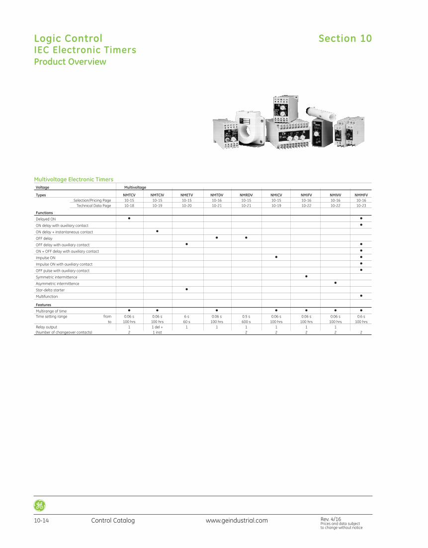
Product Overview
Multivoltage Electronic Timers Voltage Multivoltage
Types NMTCV NMTCIV NMETV NMTDV NMRDV NMICV NMIFV NMIVV NMMFV Selection/Pricing Page 10-15 10-15 10-15 10-16 10-15 10-15 10-16 10-16 10-16 Technical Data Page 10-18 10-19 10-20 10-21 10-21 10-19 10-22 10-22 10-23
Functions
Delayed ON • • ON delay with auxiliary contact • ON delay + instantaneous contact • OFF delay • • OFF delay with auxiliary contact • • ON + OFF delay with auxiliary contact • Impulse ON • • Impulse ON with auxiliary contact • OFF pulse with auxiliary contact • Symmetric intermittence • Asymmetric intermittence • Star-delta starter • Multifunction • Features
Multirange of time • • • • • • • Time setting range from 0.06 s 0.06 s 6 s 0.06 s 0.5 s 0.06 s 0.06 s 0.06 s 0.6 s to 100 hrs 100 hrs 60 s 100 hrs 600 s 100 hrs 100 hrs 100 hrs 100 hrs Relay output 1 1 del + 1 1 1 1 1 1 (Number of changeover contacts) 2 1 inst 2 2 2 2 2
Section 10Logic ControlIEC Electronic Timers
10-14 Control Catalog Rev. 4/16Prices and data subject to change without notice
www.geindustrial.com
Multivoltage Electronic Timers
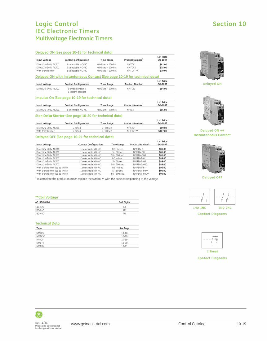
Delayed ON (See page 10-18 for technical data) List Price Input Voltage Contact Configuration Time Range Product Number1 GO-10RT
Direct 24-240V AC/DC 1 selectable NO-NC 0.06 sec. - 100 hrs NMTCV $61.00 Direct 24-240V AC/DC 2 selectable NO-NC 0.06 sec. - 100 hrs NMTCV2 $75.00 With transformer 1 selectable NO-NC 0.06 sec. - 100 hrs NMTCVT** $79.00
Delayed ON with Instantaneous Contact (See page 10-19 for technical data) List Price Input Voltage Contact Configuration Time Range Product Number GO-10RT
Direct 24-240V AC/DC 1 timed contact + 0.06 sec. - 100 hrs NMTCIV $64.00 1 instant contact
Impulse On (See page 10-19 for technical data) List Price Input Voltage Contact Configuration Time Range Product Number1 GO-10RT
Direct 24-240V AC/DC 1 selectable NO-NC 0.06 sec. - 100 hrs NMICV $65.00
Star-Delta Starter (See page 10-20 for technical data) List Price Input Voltage Contact Configuration Time Range Product Number1 GO-10RT
Direct 24-240V AC/DC 2 timed 6 - 60 sec. NMETV $89.00 With transformer 2 timed 6 - 60 sec. NMETVT** $107.00
Delayed OFF (See page 10-21 for technical data) List Price Input Voltage Contact Configuration Time Range Product Number1 GO-10RT
Direct 24-240V AC/DC 1 selectable NO-NC 0.5 - 6 sec. NMRDV-6 $81.00 Direct 24-240V AC/DC 1 selectable NO-NC 5 - 60 sec. NMRDV-60 $81.00 Direct 24-240V AC/DC 1 selectable NO-NC 50 - 600 sec. NMRDV-600 $81.00 Direct 24-240V AC/DC 2 selectable NO-NC 0.5 - 6 sec. NMRDV2-6 $89.00 Direct 24-240V AC/DC 2 selectable NO-NC 5 - 60 sec. NMRDV2-60 $89.00 Direct 24-240V AC/DC 2 selectable NO-NC 50 - 600 sec. NMRDV2-600 $89.00 With transformer (up to 440V) 1 selectable NO-NC 0.5 - 6 sec. NMRDVT-6** $93.00 With transformer (up to 440V) 1 selectable NO-NC 5 - 60 sec. NMRDVT-60** $93.00 With transformer (up to 440V) 1 selectable NO-NC 50 - 600 sec. NMRDVT-600** $93.00
1To complete the product number, replace the symbol ** with the code corresponding to the voltage.
Delayed ON
Delayed ON w/ Instantaneous Contact
Delayed OFF
Contact Diagrams
Contact Diagrams
**Coil VoltageAC (50/60 Hz) Coil Digits
110-125 AJ200-240 AM380-400 AU
Technical Data Type See Page
NMTCV 10-18 NMTCIV 10-19 NMICV 10-19 NMETV 10-20 NMRDV 10-21
1NO-1NC 2NO-2NC
2 Timed
Section 10
Rev. 4/16Prices and data subject to change without notice
Logic ControlIEC Electronic Timers
10-15Control Catalogwww.geindustrial.com
www.geindustrial.com Rev. 4/16Prices and data subject to change without notice
Control Catalog10-16
Logic ControlIEC Electronic Timers
Section 10
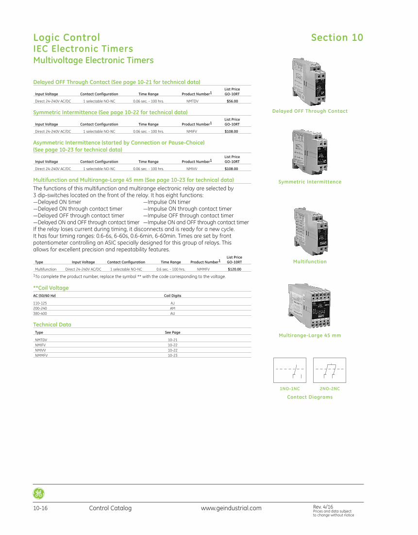
Delayed OFF Through Contact (See page 10-21 for technical data) List Price Input Voltage Contact Configuration Time Range Product Number1 GO-10RT
Direct 24-240V AC/DC 1 selectable NO-NC 0.06 sec. - 100 hrs. NMTDV $56.00
Symmetric Intermittence (See page 10-22 for technical data) List Price Input Voltage Contact Configuration Time Range Product Number1 GO-10RT
Direct 24-240V AC/DC 1 selectable NO-NC 0.06 sec. - 100 hrs. NMIFV $108.00
Asymmetric Intermittence (started by Connection or Pause-Choice)(See page 10-23 for technical data) List Price Input Voltage Contact Configuration Time Range Product Number1 GO-10RT
Direct 24-240V AC/DC 1 selectable NO-NC 0.06 sec. - 100 hrs. NMIVV $108.00
Multifunction and Multirange-Large 45 mm (See page 10-23 for technical data)The functions of this multifunction and multirange electronic relay are selected by 3 dip-switches located on the front of the relay. It has eight functions:—Delayed ON timer —Impulse ON timer—Delayed ON through contact timer —Impulse ON through contact timer—Delayed OFF through contact timer —Impulse OFF through contact timer—Delayed ON and OFF through contact timer —Impulse ON and OFF through contact timerIf the relay loses current during timing, it disconnects and is ready for a new cycle. It has four timing ranges: 0.6-6s, 6-60s, 0.6-6min, 6-60min. Times are set by front potentiometer controlling an ASIC specially designed for this group of relays. This allows for excellent precision and repeatability features. List Price Type Input Voltage Contact Configuration Time Range Product Number1 GO-10RT
Multifunction Direct 24-240V AC/DC 1 selectable NO-NC 0.6 sec. - 100 hrs. NMMFV $120.00
1To complete the product number, replace the symbol ** with the code corresponding to the voltage.
**Coil VoltageAC (50/60 Hz) Coil Digits
110-125 AJ200-240 AM380-400 AU
Technical Data Type See Page
NMTDV 10-21 NMIFV 10-22 NMIVV 10-22 NMMFV 10-23
Multivoltage Electronic Timers
Delayed OFF Through Contact
Symmetric Intermittence
Multifunction
Multirange-Large 45 mm
Contact Diagrams
1NO-1NC 2NO-2NC
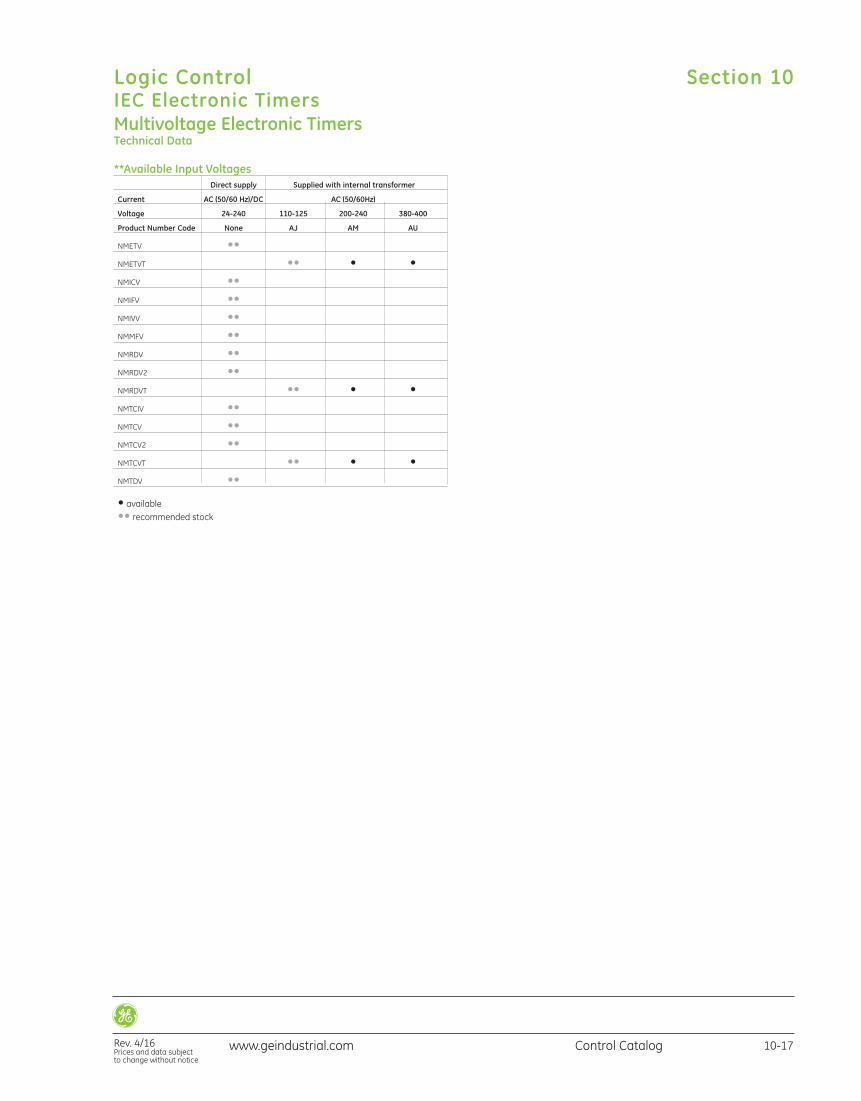
**Available Input Voltages Direct supply Supplied with internal transformer
Current AC (50/60 Hz)/DC AC (50/60Hz)
Voltage 24-240 110-125 200-240 380-400
Product Number Code None AJ AM AU
NMETV •• NMETVT •• • • NMICV •• NMIFV •• NMIVV •• NMMFV •• NMRDV •• NMRDV2 •• NMRDVT •• • • NMTCIV •• NMTCV •• NMTCV2 •• NMTCVT •• • • NMTDV ••
• available •• recommended stock
www.geindustrial.com Control Catalog 10-17
Logic ControlIEC Electronic Timers
Rev. 4/16Prices and data subject to change without notice
Section 10
Multivoltage Electronic TimersTechnical Data
Multivoltage Electronic TimersTechnical Data
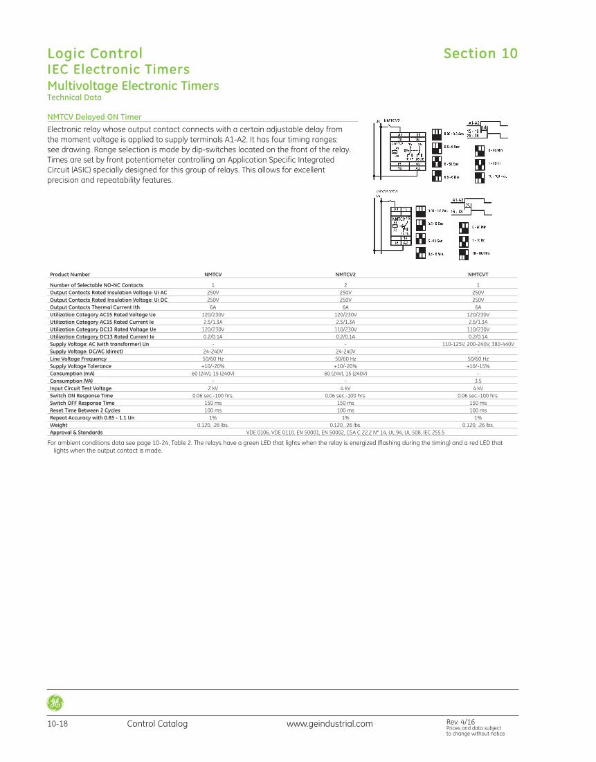
NMTCV Delayed ON TimerElectronic relay whose output contact connects with a certain adjustable delay from the moment voltage is applied to supply terminals A1-A2. It has four timing ranges: see drawing. Range selection is made by dip-switches located on the front of the relay.Times are set by front potentiometer controlling an Application Specific IntegratedCircuit (ASIC) specially designed for this group of relays. This allows for excellent precision and repeatability features.
Product Number NMTCV NMTCV2 NMTCVT
Number of Selectable NO-NC Contacts 1 2 1 Output Contacts Rated Insulation Voltage: Ui AC 250V 250V 250V Output Contacts Rated Insulation Voltage: Ui DC 250V 250V 250V Output Contacts Thermal Current Ith 6A 6A 6A Utilization Category AC15 Rated Voltage Ue 120/230V 120/230V 120/230V Utilization Category AC15 Rated Current Ie 2.5/1.3A 2.5/1.3A 2.5/1.3A Utilization Category DC13 Rated Voltage Ue 120/230V 110/230V 110/230V Utilization Category DC13 Rated Current Ie 0.2/0.1A 0.2/0.1A 0.2/0.1A Supply Voltage: AC (with transformer) Un - - 110-125V, 200-240V, 380-440V Supply Voltage: DC/AC (direct) 24-240V 24-240V - Line Voltage Frequency 50/60 Hz 50/60 Hz 50/60 Hz Supply Voltage Tolerance +10/-20% +10/-20% +10/-15% Consumption (mA) 60 (24V), 15 (240V) 60 (24V), 15 (240V) - Consumption (VA) - - 3.5 Input Circuit Test Voltage 2 kV 4 kV 4 kV Switch ON Response Time 0.06 sec.-100 hrs. 0.06 sec.-100 hrs. 0.06 sec.-100 hrs. Switch OFF Response Time 150 ms 150 ms 150 ms Reset Time Between 2 Cycles 100 ms 100 ms 100 ms Repeat Accuracy with 0.85 - 1.1 Un 1% 1% 1% Weight 0.120, .26 lbs. 0.120, .26 lbs. 0.120, .26 lbs. Approval & Standards VDE 0106, VDE 0110, EN 50001, EN 50002, CSA C 22.2 N° 14, UL 94, UL 508, IEC 255.5
For ambient conditions data see page 10-24, Table 2. The relays have a green LED that lights when the relay is energized (flashing during the timing) and a red LED thatlights when the output contact is made.
Section 10Logic ControlIEC Electronic Timers
10-18 Control Catalog Rev. 4/16Prices and data subject to change without notice
www.geindustrial.com
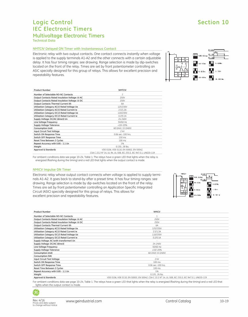
NMTCIV Delayed ON Timer with Instantaneous ContactElectronic relay with two output contacts. One contact connects instantly when voltageis applied to the supply terminals A1-A2 and the other connects with a certain adjustabledelay. It has four timing ranges: see drawing. Range selection is made by dip-switcheslocated on the front of the relay. Times are set by front potentiometer controlling anASIC specially designed for this group of relays. This allows for excellent precision andrepeatability features.
Product Number NMTCIV
Number of Selectable NO-NC Contacts 2 Output Contacts Rated Insulation Voltage: Ui AC 250V Output Contacts Rated Insulation Voltage: Ui DC 250V Output Contacts Thermal Current Ith 6A Utilization Category AC15 Rated Voltage Ue 125/230V Utilization Category AC15 Rated Current Ie 2.5/1.3A Utilization Category DC13 Rated Voltage Ue 110/230V Utilization Category DC13 Rated Current Ie 0.2/0.1A Supply Voltage: DC/AC (direct) Un 24-240V Line Voltage Frequency 50/60 Hz Supply Voltage Tolerance +10/-20% Consumption (mA) 60 (24V), 15 (240V) Input Circuit Test Voltage 2 kV Switch ON Response Time 0.06 sec.-100 hrs. Switch OFF Response Time 150 ms Reset Time Between 2 Cycles 100 ms Repeat Accuracy with 0.85 - 1.1 Un 1% Weight 0.130, .28 lbs. Approval & Standards VDE 0106, VDE 0110, EN 50002, EN 50042, CSA C 22.2 N° 14, UL 94, UL 508, IEC 255.5, IEC 947.5.1, UNE20-119
For ambient conditions data see page 10-24, Table 1. The relays have a green LED that lights when the relay is energized (flashing during the timing) and a red LED that lights when the output contact is made.
NMICV Impulse ON TimerElectronic relay whose output contact connects when voltage is applied to supply termi-nals A1-A2. It goes back to stand-by after a preset time. It has four timing ranges: seedrawing. Range selection is made by dip-switches located on the front of the relay.Times are set by front potentiometer controlling an Application Specific IntegratedCircuit (ASIC) specially designed for this group of relays. This allows for excellent precision and repeatability features.
Product Number NMICV
Number of Selectable NO-NC Contacts 1 Output Contacts Rated Insulation Voltage: Ui AC 250V Output Contacts Rated Insulation Voltage: Ui DC 250V Output Contacts Thermal Current Ith 6A Utilization Category AC15 Rated Voltage Ue 125/230V Utilization Category AC15 Rated Current Ie 2.5/1.3A Utilization Category DC13 Rated Voltage Ue 110/230V Utilization Category DC13 Rated Current Ie 0.2/0.1A Supply Voltage: AC (with transformer) Un - Supply Voltage: DC/AC (direct) 24-240V Line Voltage Frequency 50/60 Hz Supply Voltage Tolerance +10/-20% Consumption (mA) 60 (24V) 15 (240V) Consumption (VA) - Input Circuit Test Voltage 2 kV Switch ON Response Time 100 ms Switch OFF Response Time 0.06 sec.-100 hrs. Reset Time Between 2 Cycles 100 ms Repeat Accuracy with 0.85 - 1.1 Un 1% Weight 0.120, .26 lbs. Approval & Standards VDE 0106, VDE 0110, EN 50002, EN 50042, CSA C 22.2 N° 14, UL 508, IEC 255.5, IEC 947.5.1, UNE20-119
For ambient conditions data see page 10-24, Table 1. The relays have a green LED that lights when the relay is energized (flashing during the timing) and a red LED thatlights when the output contact is made.
Multivoltage Electronic TimersTechnical Data
Section 10
Rev. 4/16Prices and data subject to change without notice
Logic ControlIEC Electronic Timers
10-19Control Catalogwww.geindustrial.com
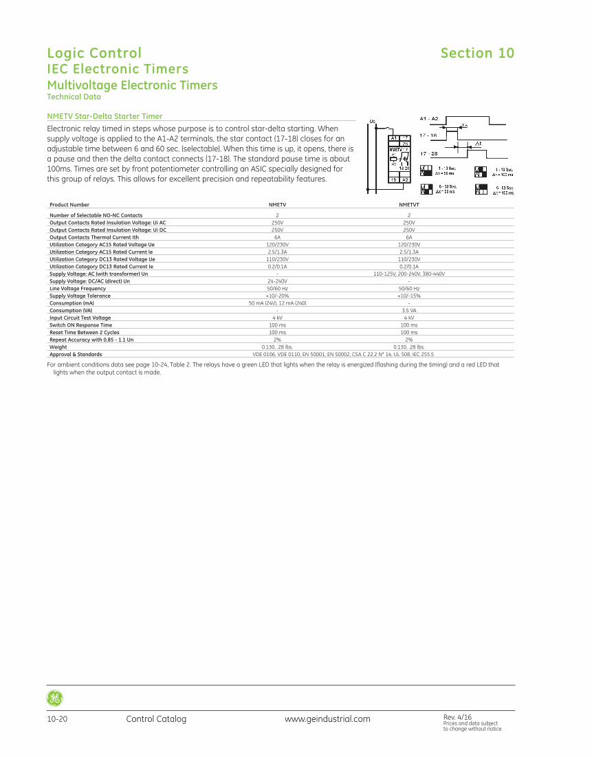
Product Number NMETV NMETVT
Number of Selectable NO-NC Contacts 2 2 Output Contacts Rated Insulation Voltage: Ui AC 250V 250V Output Contacts Rated Insulation Voltage: Ui DC 250V 250V Output Contacts Thermal Current Ith 6A 6A Utilization Category AC15 Rated Voltage Ue 120/230V 120/230V Utilization Category AC15 Rated Current Ie 2.5/1.3A 2.5/1.3A Utilization Category DC13 Rated Voltage Ue 110/230V 110/230V Utilization Category DC13 Rated Current Ie 0.2/0.1A 0.2/0.1A Supply Voltage: AC (with transformer) Un - 110-125V, 200-240V, 380-440V Supply Voltage: DC/AC (direct) Un 24-240V - Line Voltage Frequency 50/60 Hz 50/60 Hz Supply Voltage Tolerance +10/-20% +10/-15% Consumption (mA) 50 mA (24V), 12 mA (240) - Consumption (VA) - 3.5 VA Input Circuit Test Voltage 4 kV 4 kV Switch ON Response Time 100 ms 100 ms Reset Time Between 2 Cycles 100 ms 100 ms Repeat Accuracy with 0.85 - 1.1 Un 2% 2% Weight 0.130, .28 lbs. 0.130, .28 lbs. Approval & Standards VDE 0106, VDE 0110, EN 50001, EN 50002, CSA C 22.2 N° 14, UL 508, IEC 255.5
For ambient conditions data see page 10-24, Table 2. The relays have a green LED that lights when the relay is energized (flashing during the timing) and a red LED thatlights when the output contact is made.
Multivoltage Electronic TimersTechnical Data
NMETV Star-Delta Starter TimerElectronic relay timed in steps whose purpose is to control star-delta starting. When supply voltage is applied to the A1-A2 terminals, the star contact (17-18) closes for anadjustable time between 6 and 60 sec. (selectable). When this time is up, it opens, there isa pause and then the delta contact connects (17-18). The standard pause time is about100ms. Times are set by front potentiometer controlling an ASIC specially designed forthis group of relays. This allows for excellent precision and repeatability features.
Section 10Logic ControlIEC Electronic Timers
10-20 Control Catalog Rev. 4/16Prices and data subject to change without notice
www.geindustrial.com
Multivoltage Electronic TimersTechnical Data
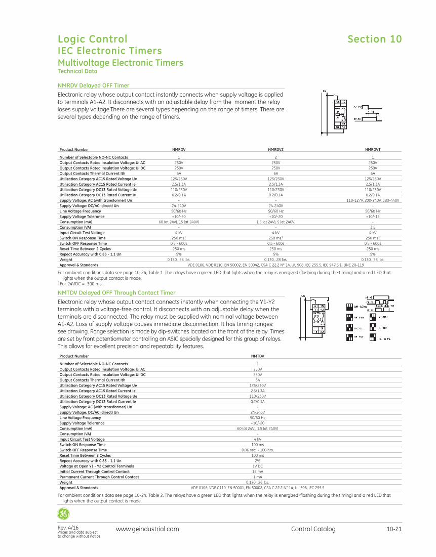
NMRDV Delayed OFF TimerElectronic relay whose output contact instantly connects when supply voltage is appliedto terminals A1-A2. It disconnects with an adjustable delay from the moment the relayloses supply voltage.There are several types depending on the range of timers. There areseveral types depending on the range of timers.
Product Number NMRDV NMRDV2 NMRDVT
Number of Selectable NO-NC Contacts 1 2 1 Output Contacts Rated Insulation Voltage: Ui AC 250V 250V 250V Output Contacts Rated Insulation Voltage: Ui DC 250V 250V 250V Output Contacts Thermal Current Ith 6A 6A 6A Utilization Category AC15 Rated Voltage Ue 125/230V 125/230V 125/230V Utilization Category AC15 Rated Current Ie 2.5/1.3A 2.5/1.3A 2.5/1.3A Utilization Category DC13 Rated Voltage Ue 110/230V 110/230V 110/230V Utilization Category DC13 Rated Current Ie 0.2/0.1A 0.2/0.1A 0.2/0.1A Supply Voltage: AC (with transformer) Un - - 110-127V, 200-240V, 380-440V Supply Voltage: DC/AC (direct) Un 24-240V 24-240V - Line Voltage Frequency 50/60 Hz 50/60 Hz 50/60 Hz Supply Voltage Tolerance +10/-20 +10/-20 +10/-15 Consumption (mA) 60 (at 24V), 15 (at 240V) 1.5 (at 24V), 5 (at 240V) - Consumption (VA) - - 3.5 Input Circuit Test Voltage 4 kV 4 kV 4 kV Switch ON Response Time 250 ms1 250 ms1 250 ms1
Switch OFF Response Time 0.5 - 600s 0.5 - 600s 0.5 - 600s Reset Time Between 2 Cycles 250 ms 250 ms 250 ms Repeat Accuracy with 0.85 - 1.1 Un 5% 5% 5% Weight 0.130, .28 lbs. 0.130, .28 lbs. 0.130, .28 lbs. Approval & Standards VDE 0106, VDE 0110, EN 50002, EN 50042, CSA C 22.2 N° 14, UL 508, IEC 255.5, IEC 947.5.1, UNE 20-119
For ambient conditions data see page 10-24, Table 1. The relays have a green LED that lights when the relay is energized (flashing during the timing) and a red LED thatlights when the output contact is made.
1For 24VDC = 300 ms.
NMTDV Delayed OFF Through Contact TimerElectronic relay whose output contact connects instantly when connecting the Y1-Y2terminals with a voltage-free control. It disconnects with an adjustable delay when theterminals are disconnected. The relay must be supplied with nominal voltage betweenA1-A2. Loss of supply voltage causes immediate disconnection. It has timing ranges: see drawing. Range selection is made by dip-switches located on the front of the relay. Timesare set by front potentiometer controlling an ASIC specially designed for this group of relays.This allows for excellent precision and repeatability features.
Product Number NMTDV
Number of Selectable NO-NC Contacts 1 Output Contacts Rated Insulation Voltage: Ui AC 250V Output Contacts Rated Insulation Voltage: Ui DC 250V Output Contacts Thermal Current Ith 6A Utilization Category AC15 Rated Voltage Ue 125/230V Utilization Category AC15 Rated Current Ie 2.5/1.3A Utilization Category DC13 Rated Voltage Ue 110/230V Utilization Category DC13 Rated Current Ie 0.2/0.1A Supply Voltage: AC (with transformer) Un - Supply Voltage: DC/AC (direct) Un 24-240V Line Voltage Frequency 50/60 Hz Supply Voltage Tolerance +10/-20 Consumption (mA) 60 (at 24V), 1.5 (at 240V) Consumption (VA) - Input Circuit Test Voltage 4 kV Switch ON Response Time 100 ms Switch OFF Response Time 0.06 sec. - 100 hrs. Reset Time Between 2 Cycles 100 ms Repeat Accuracy with 0.85 - 1.1 Un 2% Voltage at Open Y1 - Y2 Control Terminals 1V DC Initial Current Through Control Contact 15 mA Permanent Current Through Control Contact 1 mA Weight 0.120, .26 lbs. Approval & Standards VDE 0106, VDE 0110, EN 50001, EN 50002, CSA C 22.2 N° 14, UL 508, IEC 255.5
For ambient conditions data see page 10-24, Table 2. The relays have a green LED that lights when the relay is energized (flashing during the timing) and a red LED thatlights when the output contact is made.
Section 10
Rev. 4/16Prices and data subject to change without notice
Logic ControlIEC Electronic Timers
10-21Control Catalogwww.geindustrial.com
Multivoltage Electronic TimersTechnical Data
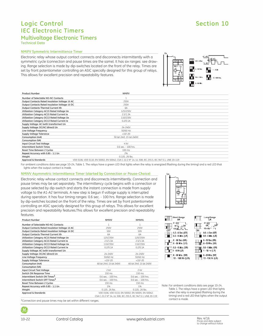
NMIFV Symmetric Intermittence TimerElectronic relay whose output contact connects and disconnects intermittently with asymmetric cycle (connection and pause times are the same). It has six ranges: see draw-ing. Range selection is made by dip-switches located on the front of the relay. Times areset by front potentiometer controlling an ASIC specially designed for this group of relays.This allows for excellent precision and repeatability features.
Product Number NMIFV
Number of Selectable NO-NC Contacts 1 Output Contacts Rated Insulation Voltage: Ui AC 250V Output Contacts Rated Insulation Voltage: Ui DC 250V Output Contacts Thermal Current Ith 6A Utilization Category AC15 Rated Voltage Ue 125/230V Utilization Category AC15 Rated Current Ie 2.5/1.3A Utilization Category DC13 Rated Voltage Ue 110/230V Utilization Category DC13 Rated Current Ie 0.2/0.1A Supply Voltage: AC (with transformer) Un - Supply Voltage: DC/AC (direct) Un 24-240V Line Voltage Frequency 50/60 Hz Supply Voltage Tolerance +10/-20 Consumption (mA) 50 (at 24V), 15 (at 240V) Consumption (VA) - Input Circuit Test Voltage 4 kV Intermittent Switch Times 0.6 sec. - 100 hrs. Reset Time Between 2 Cycles 100 ms Repeat Accuracy with 0.85 - 1.1 Un 2% Weight 0.120, .26 lbs. Approval & Standards VDE 0106, VDE 0110, EN 50002, EN 50042, CSA C 22.2 N° 14, UL 508, IEC 255.5, IEC 947.5.1, UNE 20-119
For ambient conditions data see page 10-24, Table 1. The relays have a green LED that lights when the relay is energized (flashing during the timing) and a red LED thatlights when the output contact is made.
NMIVV Asymmetric Intermittence Timer (started by Connection or Pause-Choice)Electronic relay whose contact connects and disconnects intermittently. Connection andpause times may be set separately. The intermittency cycle begins with a connection orpause selected by dip-switch and starts the instant connection is made from supplyvoltage to the A1-A2 terminals. A new step is begun if voltage supply is interrupted during operation. It has four timing ranges: 0.6 sec. - 100 hrs. Range selection is madeby dip-switches located on the front of the relay. Times are set by front potentiometercontrolling an ASIC specially designed for this group of relays. This allows for excellentprecision and repeatability features.This allows for excellent precision and repeatabilityfeatures. Product Number NMIVV NMIVVL
Number of Selectable NO-NC Contacts 1 1 Output Contacts Rated Insulation Voltage: Ui AC 250V 250V Output Contacts Rated Insulation Voltage: Ui DC 50V 50V Output Contacts Thermal Current Ith 6A 6A Utilization Category AC15 Rated Voltage Ue 125/230V 120/230V Utilization Category AC15 Rated Current Ie 2.5/1.3A 2.5/1.3A Utilization Category DC13 Rated Voltage Ue 110/230V 110/230V Utilization Category DC13 Rated Current Ie 0.2/0.1A 0.2/0.1A Supply Voltage: AC (with transformer) Un - - Supply Voltage: DC/AC (direct) Un 24-240V 24-240V Line Voltage Frequency 50/60 Hz 50/60 Hz Supply Voltage Tolerance +10/-20 +10/-20 Consumption (mA) 60 (at 24V), 15 (at 240V) 60 (at 24V), 15 (at 240V) Consumption (VA) - - Input Circuit Test Voltage 2 kV 2 kV Switch ON Response Time 150 ms 150 ms Intermittent Switch ON Times1 0.6 sec. - 100 hrs. 0.6 sec. - 100 hrs. Intermittent Switch OFF Times1 0.6 sec. - 100 hrs. 0.6 sec. - 100 hrs. Reset Time Between 2 Cycles 150 ms 150 ms Repeat Accuracy with 0.85 - 1.1 Un 1% 1% Weight 0.120, .26 lbs. 0.120, .26 lbs. Approval & Standards VDE 0106, VDE 0110, EN 50002, EN 50005, EN 50042, CSA C 22.2 N° 14, UL 508, IEC 255.5, IEC 947.5.1, UNE 20-119
1Connection and pause times may be set within different ranges.
Note: For ambient conditions data see page 10-24,Table 1. The relays have a green LED that lightswhen the relay is energized (flashing during thetiming) and a red LED that lights when the outputcontact is made.
Section 10Logic ControlIEC Electronic Timers
10-22 Control Catalog Rev. 4/16Prices and data subject to change without notice
www.geindustrial.com
Multivoltage Electronic TimersTechnical Data
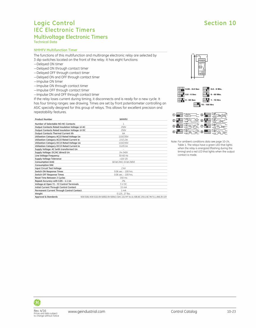
NMMFV Multifunction TimerThe functions of this multifunction and multirange electronic relay are selected by 3 dip-switches located on the front of the relay. It has eight functions:—Delayed ON timer—Delayed ON through contact timer—Delayed OFF through contact timer—Delayed ON and OFF through contact timer—Impulse ON timer—Impulse ON through contact timer—Impulse OFF through contact timer—Impulse ON and OFF through contact timerIf the relay loses current during timing, it disconnects and is ready for a new cycle. It has four timing ranges: see drawing. Times are set by front potentiometer controlling anASIC specially designed for this group of relays. This allows for excellent precision andrepeatability features.
Product Number NMMFV
Number of Selectable NO-NC Contacts 1 Output Contacts Rated Insulation Voltage: Ui AC 250V Output Contacts Rated Insulation Voltage: Ui DC 250V Output Contacts Thermal Current Ith 6A Utilization Category AC15 Rated Voltage Ue 110/230V Utilization Category AC15 Rated Current Ie 2.5/1.3A Utilization Category DC13 Rated Voltage Ue 110/230V Utilization Category DC13 Rated Current Ie 0.2/0.1A Supply Voltage: AC (with transformer) Un - Supply Voltage: DC/AC (direct) Un 24-240V Line Voltage Frequency 50-60 Hz Supply Voltage Tolerance +10/-20 Consumption (mA) 60 (at 24V), 15 (at 240V) Consumption (VA) - Input Circuit Test Voltage 2 kV Switch ON Response Times 0.06 sec. - 100 hrs. Switch OFF Response Times 0.06 sec. - 100 hrs. Reset Time Between 2 Cycles 150 ms Repeat Accuracy with 0.85 - 1.1 Un 2% Voltage at Open Y1 - Y2 Control Terminals 5 V DC Initial Current Through Control Contact 15 mA Permanent Current Through Control Contact 1 mA Weight 0.125, .27 lbs. Approval & Standards VDE 0106, VDE 0110, EN 50002, EN 50042, CSA C 22.2 N° 14, UL 508, IEC 255.5, IEC 947.5.1, UNE 20-119
Note: For ambient conditions data see page 10-24,Table 1. The relays have a green LED that lightswhen the relay is energized (flashing during thetiming) and a red LED that lights when the outputcontact is made.
Section 10
Rev. 4/16Prices and data subject to change without notice
Logic ControlIEC Electronic Timers
10-23Control Catalogwww.geindustrial.com
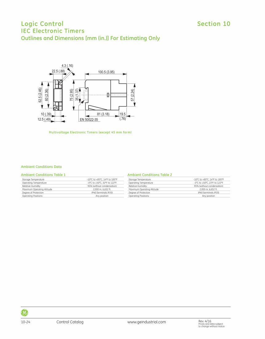
Outlines and Dimensions [mm (in.)] For Estimating Only
Multivoltage Electronic Timers (except 45 mm form)
Ambient Conditions Table 1 Storage Temperature -10°C to +85°C, 14°F to 185°F Operating Temperature -0°C to +50°C, 32°F to 122°F Relative Humidity 95% (without condensation) Maximum Operating Altitude 2,000 m, 6,652 ft. Degree of Protection IP40 (terminals IP20) Operating Positions Any position
Ambient Conditions Table 2 Storage Temperature -10°C to +85°C, 14°F to 185°F Operating Temperature -5°C to +50°C, 23°F to 122°F Relative Humidity 95% (without condensation) Maximum Operating Altitude 2,000 m, 6,652 ft. Degree of Protection IP40 (terminals IP20) Operating Positions Any position
Ambient Conditions Data
Section 10Logic ControlIEC Electronic Timers
10-24 Control Catalog Rev. 4/16Prices and data subject to change without notice
www.geindustrial.com
Product Overview
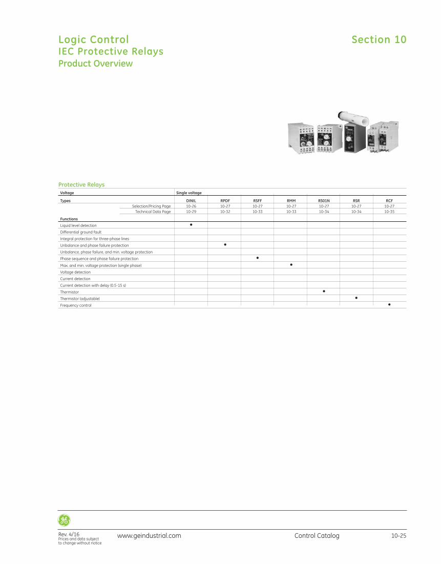
Protective Relays Voltage Single voltage
Types DINIL RPDF RSFF RMM RS01N RSR RCF Selection/Pricing Page 10-26 10-27 10-27 10-27 10-27 10-27 10-27 Technical Data Page 10-29 10-32 10-33 10-33 10-34 10-34 10-35
Functions
Liquid level detection • Differential ground fault • Integral protection for three-phase lines • Unbalance and phase failure protection • Unbalance, phase failure, and min. voltage protection • Phase sequence and phase failure protection • Max. and min. voltage protection (single phase) • Voltage detection • Current detection • Current detection with delay (0.5-15 s) • Thermistor • Thermistor (adjustable) • Frequency control •
Section 10
Rev. 4/16Prices and data subject to change without notice
Logic ControlIEC Protective Relays
10-25Control Catalogwww.geindustrial.com
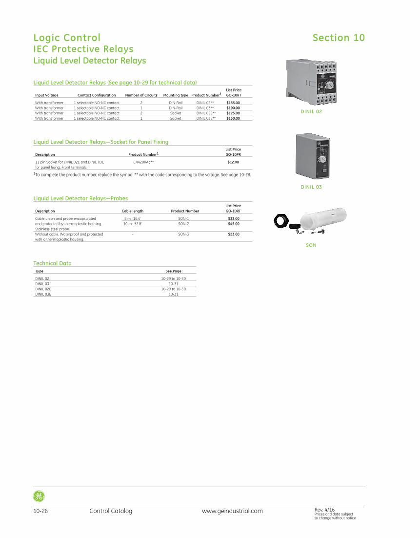
Liquid Level Detector Relays
Liquid Level Detector Relays (See page 10-29 for technical data) List Price Input Voltage Contact Configuration Number of Circuits Mounting type Product Number1 GO-10RT
With transformer 1 selectable NO-NC contact 2 DIN-Rail DINIL 02** $155.00 With transformer 1 selectable NO-NC contact 1 DIN-Rail DINIL 03** $190.00 With transformer 1 selectable NO-NC contact 2 Socket DINIL 02E** $125.00 With transformer 1 selectable NO-NC contact 1 Socket DINIL 03E** $150.00
Liquid Level Detector Relays—Socket for Panel Fixing List Price Description Product Number1 GO-10PR
11 pin Socket for DINIL 02E and DINIL 03E CR420KA3** $12.00 for panel fixing. Front terminals
1To complete the product number, replace the symbol ** with the code corresponding to the voltage. See page 10-28.
Liquid Level Detector Relays—Probes List Price Description Cable length Product Number GO-10RT
Cable union and probe encapsulated 5 m., 16.4' SON-1 $33.00 and protected by thermoplastic housing. 10 m., 32.8' SON-2 $45.00 Stainless steel probe. Without cable. Waterproof and protected - SON-3 $23.00 with a thermoplastic housing.
DINIL 02
DINIL 03
SON
Technical Data Type See Page
DINIL 02 10-29 to 10-30 DINIL 03 10-31 DINIL 02E 10-29 to 10-30 DINIL 03E 10-31
Section 10Logic ControlIEC Protective Relays
10-26 Control Catalog Rev. 4/16Prices and data subject to change without notice
www.geindustrial.com
Technical Data Type See Page
RPDF 10-32 RSFF 10-33 RMM 10-33
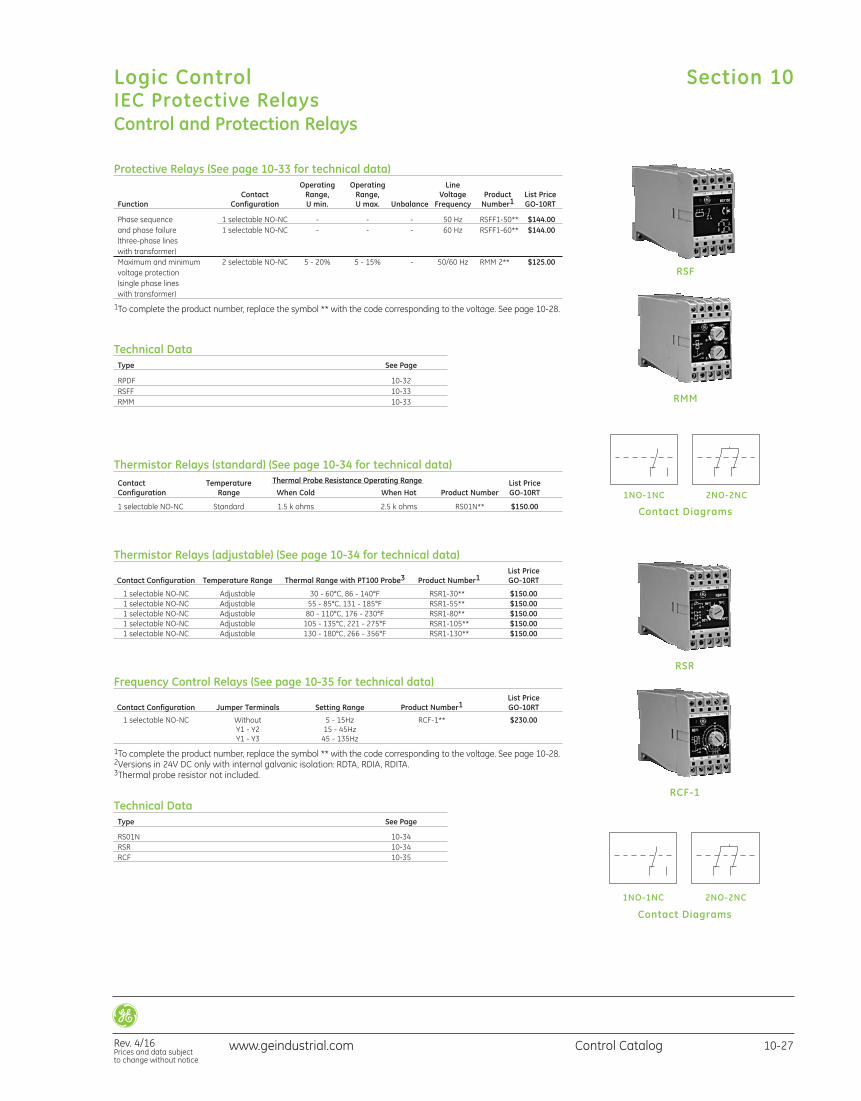
Control and Protection Relays
Protective Relays (See page 10-33 for technical data) Operating Operating Line Contact Range, Range, Voltage Product List Price Function Configuration U min. U max. Unbalance Frequency Number1 GO-10RT
Phase sequence 1 selectable NO-NC - - - 50 Hz RSFF1-50** $144.00 and phase failure 1 selectable NO-NC - - - 60 Hz RSFF1-60** $144.00 (three-phase lines with transformer) Maximum and minimum 2 selectable NO-NC 5 - 20% 5 - 15% - 50/60 Hz RMM 2** $125.00 voltage protection (single phase lines with transformer)
1To complete the product number, replace the symbol ** with the code corresponding to the voltage. See page 10-28.
RSF
RMM
Contact Diagrams
1NO-1NC 2NO-2NC
Thermistor Relays (standard) (See page 10-34 for technical data) Contact Temperature Thermal Probe Resistance Operating Range List Price Configuration Range When Cold When Hot Product Number GO-10RT
1 selectable NO-NC Standard 1.5 k ohms 2.5 k ohms RS01N** $150.00
Thermistor Relays (adjustable) (See page 10-34 for technical data) List Price Contact Configuration Temperature Range Thermal Range with PT100 Probe3 Product Number1 GO-10RT
1 selectable NO-NC Adjustable 30 - 60°C, 86 - 140°F RSR1-30** $150.00 1 selectable NO-NC Adjustable 55 - 85°C, 131 - 185°F RSR1-55** $150.00 1 selectable NO-NC Adjustable 80 - 110°C, 176 - 230°F RSR1-80** $150.00 1 selectable NO-NC Adjustable 105 - 135°C, 221 - 275°F RSR1-105** $150.00 1 selectable NO-NC Adjustable 130 - 180°C, 266 - 356°F RSR1-130** $150.00
Frequency Control Relays (See page 10-35 for technical data) List Price Contact Configuration Jumper Terminals Setting Range Product Number1 GO-10RT
1 selectable NO-NC Without 5 - 15Hz RCF-1** $230.00 Y1 - Y2 15 - 45Hz Y1 - Y3 45 - 135Hz
1To complete the product number, replace the symbol ** with the code corresponding to the voltage. See page 10-28.2Versions in 24V DC only with internal galvanic isolation: RDTA, RDIA, RDITA.3Thermal probe resistor not included.
Technical Data Type See Page
RS01N 10-34 RSR 10-34 RCF 10-35
RSR
RCF-1
Contact Diagrams
1NO-1NC 2NO-2NC
Section 10
Rev. 4/16Prices and data subject to change without notice
Logic ControlIEC Protective Relays
10-27Control Catalogwww.geindustrial.com
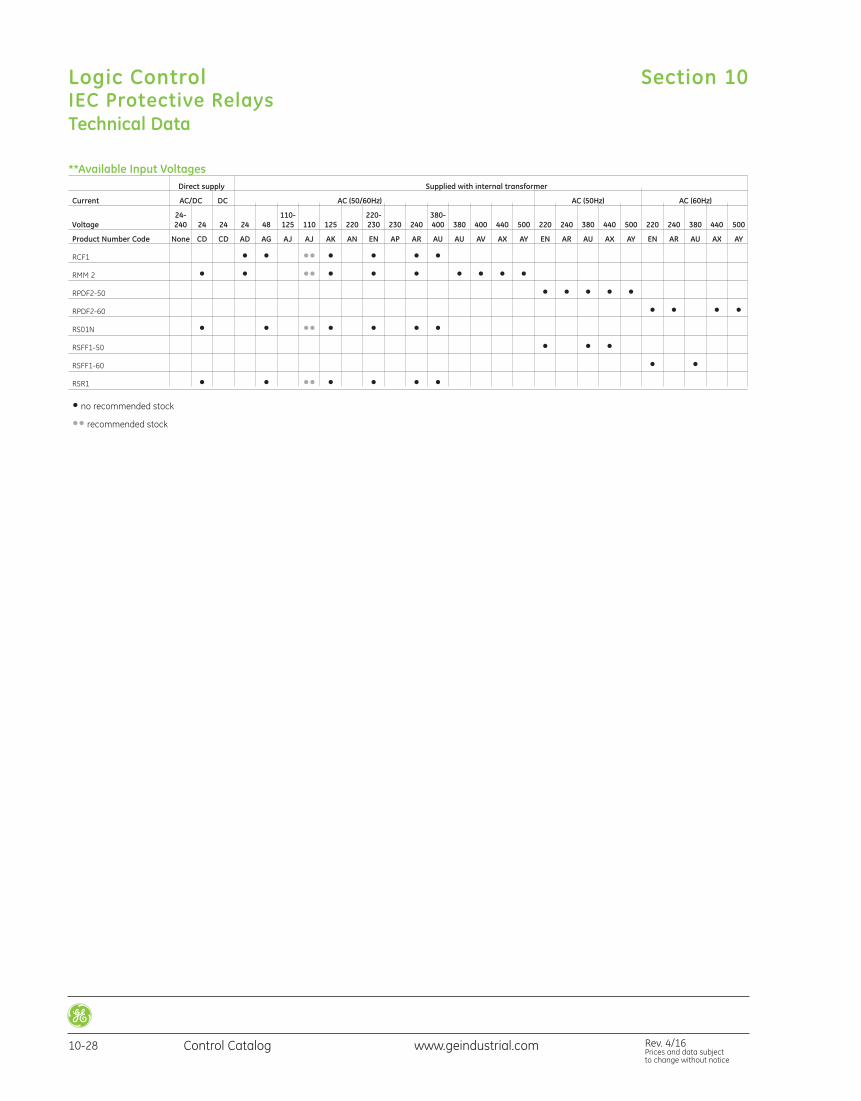
**Available Input Voltages Direct supply Supplied with internal transformer
Current AC/DC DC AC (50/60Hz) AC (50Hz) AC (60Hz)
24- 110- 220- 380- Voltage 240 24 24 24 48 125 110 125 220 230 230 240 400 380 400 440 500 220 240 380 440 500 220 240 380 440 500
Product Number Code None CD CD AD AG AJ AJ AK AN EN AP AR AU AU AV AX AY EN AR AU AX AY EN AR AU AX AY
RCF1 • • •• • • • • RMM 2 • • •• • • • • • • • RPDF2-50 • • • • • RPDF2-60 • • • • RS01N • • •• • • • • RSFF1-50 • • • RSFF1-60 • • RSR1 • • •• • • • •
• no recommended stock
•• recommended stock
Technical Data
Section 10Logic ControlIEC Protective Relays
10-28 Control Catalog Rev. 4/16Prices and data subject to change without notice
www.geindustrial.com
Technical Data
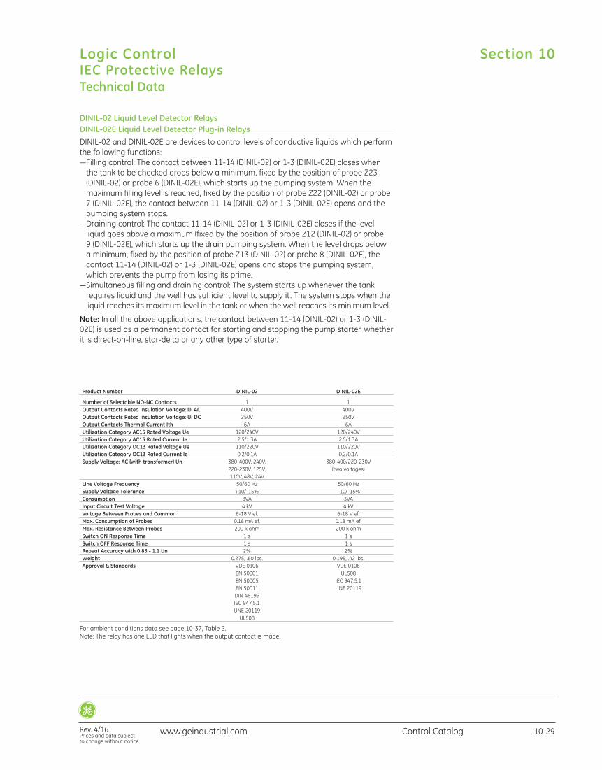
DINIL-02 Liquid Level Detector RelaysDINIL-02E Liquid Level Detector Plug-in RelaysDINIL-02 and DINIL-02E are devices to control levels of conductive liquids which performthe following functions:—Filling control: The contact between 11-14 (DINIL-02) or 1-3 (DINIL-02E) closes whenthe tank to be checked drops below a minimum, fixed by the position of probe Z23(DINIL-02) or probe 6 (DINIL-02E), which starts up the pumping system. When the maximum filling level is reached, fixed by the position of probe Z22 (DINIL-02) or probe7 (DINIL-02E), the contact between 11-14 (DINIL-02) or 1-3 (DINIL-02E) opens and thepumping system stops.
—Draining control: The contact 11-14 (DINIL-02) or 1-3 (DINIL-02E) closes if the level liquid goes above a maximum (fixed by the position of probe Z12 (DINIL-02) or probe 9 (DINIL-02E), which starts up the drain pumping system. When the level drops below a minimum, fixed by the position of probe Z13 (DINIL-02) or probe 8 (DINIL-02E), thecontact 11-14 (DINIL-02) or 1-3 (DINIL-02E) opens and stops the pumping system,which prevents the pump from losing its prime.
—Simultaneous filling and draining control: The system starts up whenever the tankrequires liquid and the well has sufficient level to supply it . The system stops when theliquid reaches its maximum level in the tank or when the well reaches its minimum level.
Note: In all the above applications, the contact between 11-14 (DINIL-02) or 1-3 (DINIL-02E) is used as a permanent contact for starting and stopping the pump starter, whetherit is direct-on-line, star-delta or any other type of starter.
Product Number DINIL-02 DINIL-02E
Number of Selectable NO-NC Contacts 1 1 Output Contacts Rated Insulation Voltage: Ui AC 400V 400V Output Contacts Rated Insulation Voltage: Ui DC 250V 250V Output Contacts Thermal Current Ith 6A 6A Utilization Category AC15 Rated Voltage Ue 120/240V 120/240V Utilization Category AC15 Rated Current Ie 2.5/1.3A 2.5/1.3A Utilization Category DC13 Rated Voltage Ue 110/220V 110/220V Utilization Category DC13 Rated Current Ie 0.2/0.1A 0.2/0.1A Supply Voltage: AC (with transformer) Un 380-400V, 240V, 380-400/220-230V 220-230V, 125V, (two voltages) 110V, 48V, 24V Line Voltage Frequency 50/60 Hz 50/60 Hz Supply Voltage Tolerance +10/-15% +10/-15% Consumption 3VA 3VA Input Circuit Test Voltage 4 kV 4 kV Voltage Between Probes and Common 6-18 V ef. 6-18 V ef. Max. Consumption of Probes 0.18 mA ef. 0.18 mA ef. Max. Resistance Between Probes 200 k ohm 200 k ohm Switch ON Response Time 1 s 1 s Switch OFF Response Time 1 s 1 s Repeat Accuracy with 0.85 - 1.1 Un 2% 2% Weight 0.275, .60 lbs. 0.195, .42 lbs. Approval & Standards VDE 0106 VDE 0106 EN 50001 UL508 EN 50005 IEC 947.5.1 EN 50011 UNE 20119 DIN 46199 IEC 947.5.1 UNE 20119 UL508
For ambient conditions data see page 10-37, Table 2.Note: The relay has one LED that lights when the output contact is made.
Section 10
Rev. 4/16Prices and data subject to change without notice
Logic ControlIEC Protective Relays
10-29Control Catalogwww.geindustrial.com
Technical Data
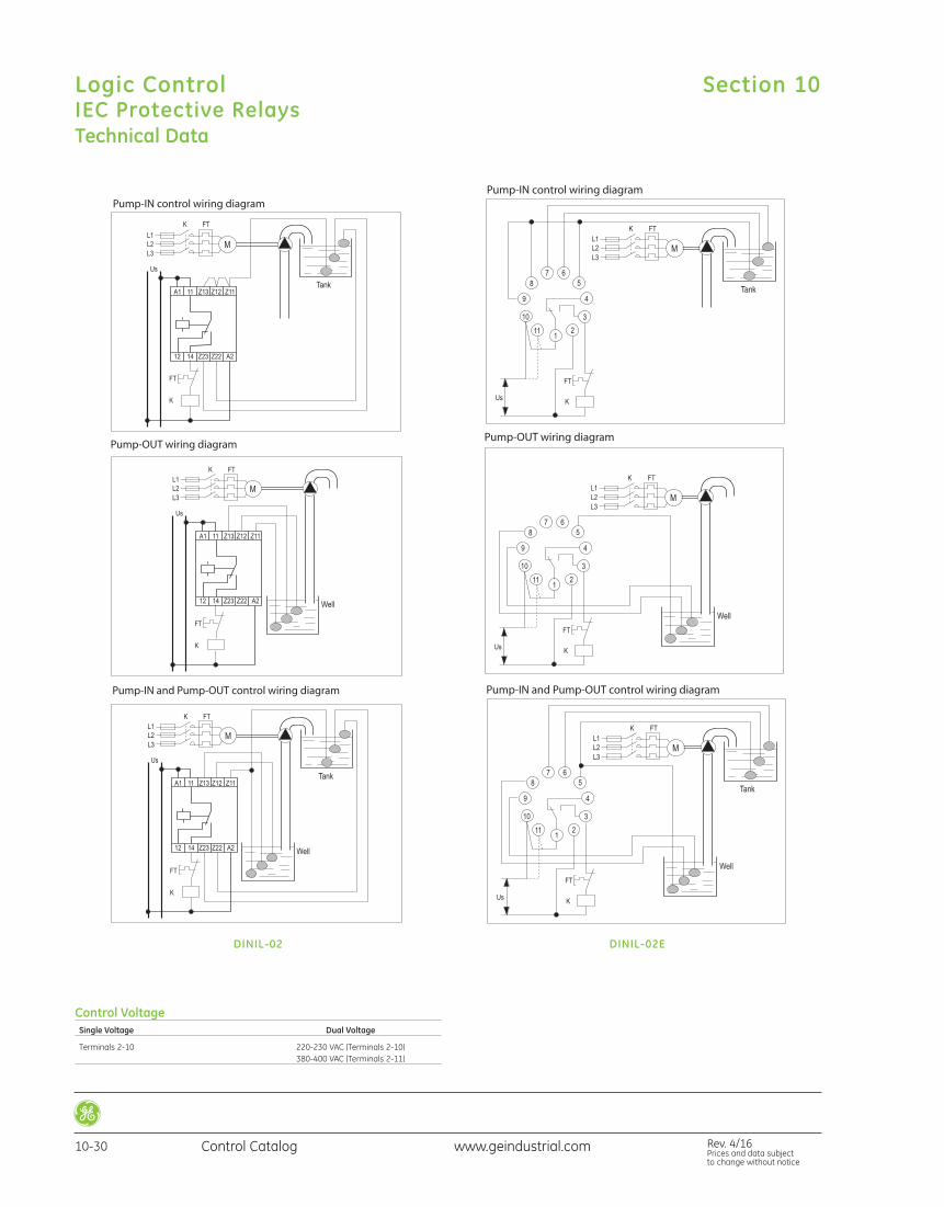
DINIL-02 DINIL-02E
Control Voltage Single Voltage Dual Voltage
Terminals 2-10 220-230 VAC (Terminals 2-10) 380-400 VAC (Terminals 2-11)
Section 10Logic ControlIEC Protective Relays
10-30 Control Catalog Rev. 4/16Prices and data subject to change without notice
www.geindustrial.com
Technical Data
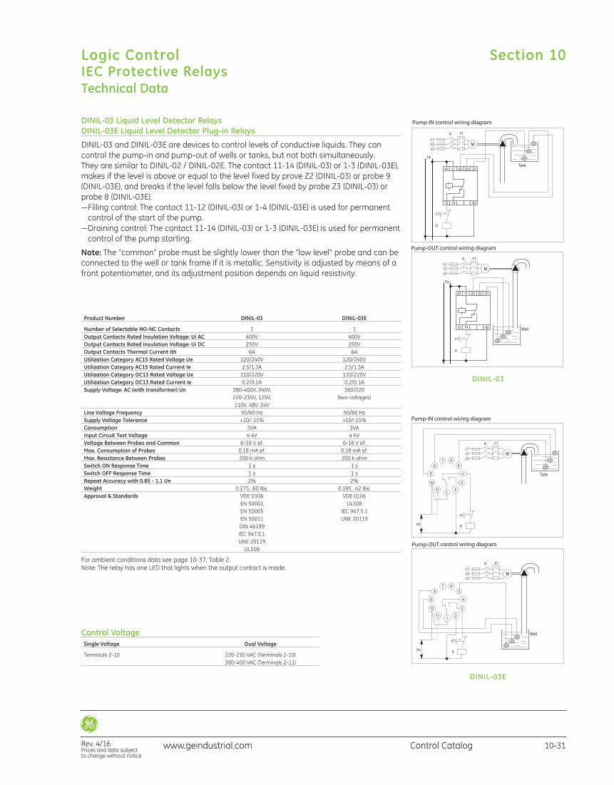
DINIL-03 Liquid Level Detector RelaysDINIL-03E Liquid Level Detector Plug-in Relays
DINIL-03 and DINIL-03E are devices to control levels of conductive liquids. They can control the pump-in and pump-out of wells or tanks, but not both simultaneously. They are similar to DINIL-02 / DINIL-02E. The contact 11-14 (DINIL-03) or 1-3 (DINIL-03E),makes if the level is above or equal to the level fixed by prove Z2 (DINIL-03) or probe 9(DINIL-03E), and breaks if the level falls below the level fixed by probe Z3 (DINIL-03) orprobe 8 (DINIL-03E).—Filling control: The contact 11-12 (DINIL-03) or 1-4 (DINIL-03E) is used for permanent control of the start of the pump.
—Draining control: The contact 11-14 (DINIL-03) or 1-3 (DINIL-03E) is used for permanentcontrol of the pump starting.
Note: The “common” probe must be slightly lower than the “low level” probe and can beconnected to the well or tank frame if it is metallic. Sensitivity is adjusted by means of afront potentiometer, and its adjustment position depends on liquid resistivity.
DINIL-03
DINIL-03E
Product Number DINIL-03 DINIL-03E
Number of Selectable NO-NC Contacts 1 1 Output Contacts Rated Insulation Voltage: Ui AC 400V 400V Output Contacts Rated Insulation Voltage: Ui DC 250V 250V Output Contacts Thermal Current Ith 6A 6A Utilization Category AC15 Rated Voltage Ue 120/240V 120/240V Utilization Category AC15 Rated Current Ie 2.5/1.3A 2.5/1.3A Utilization Category DC13 Rated Voltage Ue 110/220V 110/220V Utilization Category DC13 Rated Current Ie 0.2/0.1A 0.2/0.1A Supply Voltage: AC (with transformer) Un 380-400V, 240V, 380/220 220-230V, 125V, (two voltages) 110V, 48V, 24V Line Voltage Frequency 50/60 Hz 50/60 Hz Supply Voltage Tolerance +10/-15% +10/-15% Consumption 3VA 3VA Input Circuit Test Voltage 4 kV 4 kV Voltage Between Probes and Common 6-18 V ef. 6-18 V ef. Max. Consumption of Probes 0.18 mA ef. 0.18 mA ef. Max. Resistance Between Probes 200 k ohm 200 k ohm Switch ON Response Time 1 s 1 s Switch OFF Response Time 1 s 1 s Repeat Accuracy with 0.85 - 1.1 Un 2% 2% Weight 0.275, .60 lbs. 0.195, .42 lbs. Approval & Standards VDE 0106 VDE 0106 EN 50001 UL508 EN 50005 IEC 947.5.1 EN 50011 UNE 20119 DIN 46199 IEC 947.5.1 UNE 20119 UL508
For ambient conditions data see page 10-37, Table 2.Note: The relay has one LED that lights when the output contact is made.
Control Voltage Single Voltage Dual Voltage
Terminals 2-10 220-230 VAC (Terminals 2-10) 380-400 VAC (Terminals 2-11)
Section 10
Rev. 4/16Prices and data subject to change without notice
Logic ControlIEC Protective Relays
10-31Control Catalogwww.geindustrial.com
Technical Data
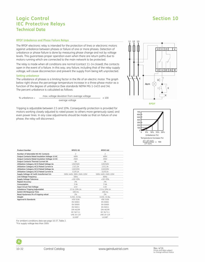
RPDF Unbalance and Phase Failure Relays
The RPDF-electronic relay is intended for the protection of lines or electronic motorsagainst unbalance between phases or failure of one or more phases. Detection of unbalance or phase failure is done by measuring phase change and not by voltage levels. This guarantees proper operation even when there are return paths due tomotors running which are connected to the main network to be protected.
The relay is made when all conditions are normal (contact 11-14 closed); the contactsopen in the event of a failure. In this way, any failure, including that of the relay supplyvoltage, will cause disconnection and prevent the supply from being left unprotected.
Setting unbalanceThe unbalance of phases is a limiting factor in the life of an electric motor. The graphbelow right shows the percentage temperature increase in a three-phase motor as afunction of the degree of unbalance (See standards NEMA MG 1-1433 and 34).The percent unbalance is calculated as follows:
max. voltage deviation from average voltage % unbalance = x 100
average voltage
Tripping is adjustable between 2.5 and 10%. Consequently protection is provided formotors working closely adjusted to rated power, to others more generously sized, andeven power lines. In any case adjustments should be made so that on failure of onephase, the relay will disconnect.
Product Number RPDF2-50 RPDF2-60
Number of Selectable NO-NC Contacts 2 2 Output Contacts Rated Insulation Voltage: Ui AC 400V 400V Output Contacts Rated Insulation Voltage: Ui DC 250V 250V Output Contacts Thermal Current Ith 6A 6A Utilization Category AC15 Rated Voltage Ue 120/240V 120/240V Utilization Category AC15 Rated Current Ie 2.5/1.3A 2.5/1.3A Utilization Category DC13 Rated Voltage Ue 110/220V 110/220V Utilization Category DC13 Rated Current Ie 0.2/0.1A 0.2/0.1A Supply Voltage: AC (with transformer) Un 500V, 440V, 380V, 240V, 220V 500V, 440V, 240V, 220V Line Voltage Frequency 50Hz 60Hz Supply Voltage Tolerance +10/-20% +10/-20% Repeat Accuracy 2% 2% Consumption 3 VA 3 VA Input Circuit Test Voltage 4 kV 4 kV Unbalance Tripping (adjustable) 2.5 to 10% Un 2.5 to 10% Un Switch ON Response Time 100 ms 100 ms Reset Hysteresis (% of tripping value) 2% 2% Weight 0.250, .55 lbs. 0.250, .55 lbs. Approval & Standards VDE 0106 VDE 0106 EN 50001 EN 50001 EN 50005 EN 50005 EN 50011 EN 50011 DIN 46199 DIN 46199 IEC 947.5.1 IEC 947.5.1 UNE 20-119 UNE 20-119 UL5081 UL5081
For ambient conditions data see page 10-37, Table 2.1For supply voltage less than 300V.
RPDF
Section 10Logic ControlIEC Protective Relays
10-32 Control Catalog Rev. 4/16Prices and data subject to change without notice
www.geindustrial.com
Technical Data
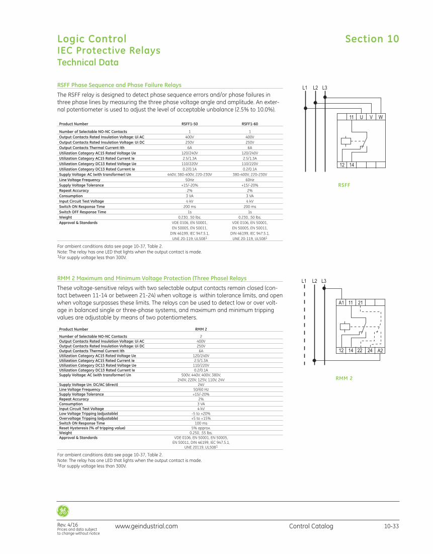
RSFF Phase Sequence and Phase Failure Relays
The RSFF relay is designed to detect phase sequence errors and/or phase failures inthree phase lines by measuring the three phase voltage angle and amplitude. An exter-nal potentiometer is used to adjust the level of acceptable unbalance (2.5% to 10.0%).
RSFF
Product Number RSFF1-50 RSFF1-60
Number of Selectable NO-NC Contacts 1 1 Output Contacts Rated Insulation Voltage: Ui AC 400V 400V Output Contacts Rated Insulation Voltage: Ui DC 250V 250V Output Contacts Thermal Current Ith 6A 6A Utilization Category AC15 Rated Voltage Ue 120/240V 120/240V Utilization Category AC15 Rated Current Ie 2.5/1.3A 2.5/1.3A Utilization Category DC13 Rated Voltage Ue 110/220V 110/220V Utilization Category DC13 Rated Current Ie 0.2/0.1A 0.2/0.1A Supply Voltage: AC (with transformer) Un 440V, 380-400V, 220-230V 380-400V, 220-230V Line Voltage Frequency 50Hz 60Hz Supply Voltage Tolerance +15/-20% +15/-20% Repeat Accuracy 2% 2% Consumption 3 VA 3 VA Input Circuit Test Voltage 4 kV 4 kV Switch ON Response Time 200 ms 200 ms Switch OFF Response Time 1s 1s Weight 0.230, .50 lbs. 0.230, .50 lbs. Approval & Standards VDE 0106, EN 50001, VDE 0106, EN 50001, EN 50005, EN 50011, EN 50005, EN 50011, DIN 46199, IEC 947.5.1, DIN 46199, IEC 947.5.1, UNE 20-119, UL5081 UNE 20-119, UL5081
For ambient conditions data see page 10-37, Table 2.Note: The relay has one LED that lights when the output contact is made.1For supply voltage less than 300V.
RMM 2 Maximum and Minimum Voltage Protection (Three Phase) Relays
These voltage-sensitive relays with two selectable output contacts remain closed (con-tact between 11-14 or between 21-24) when voltage is within tolerance limits, and openwhen voltage surpasses these limits. The relays can be used to detect low or over volt-age in balanced single or three-phase systems, and maximum and minimum trippingvalues are adjustable by means of two potentiometers.
RMM 2
Product Number RMM 2
Number of Selectable NO-NC Contacts 2 Output Contacts Rated Insulation Voltage: Ui AC 400V Output Contacts Rated Insulation Voltage: Ui DC 250V Output Contacts Thermal Current Ith 6A Utilization Category AC15 Rated Voltage Ue 120/240V Utilization Category AC15 Rated Current Ie 2.5/1.3A Utilization Category DC13 Rated Voltage Ue 110/220V Utilization Category DC13 Rated Current Ie 0.2/0.1A Supply Voltage: AC (with transformer) Un 500V, 440V, 400V, 380V, 240V, 220V, 125V, 110V, 24V Supply Voltage Un: DC/AC (direct) 24V Line Voltage Frequency 50/60 Hz Supply Voltage Tolerance +15/-20% Repeat Accuracy 2% Consumption 3 VA Input Circuit Test Voltage 4 kV Low Voltage Tripping (adjustable) -5 to +20% Overvoltage Tripping (adjustable) +5 to +15% Switch ON Response Time 100 ms Reset Hysteresis (% of tripping value) 5% approx. Weight 0.250, .55 lbs. Approval & Standards VDE 0106, EN 50001, EN 50005, EN 50011, DIN 46199, IEC 947.5.1, UNE 20119, UL5081
For ambient conditions data see page 10-37, Table 2.Note: The relay has one LED that lights when the output contact is made.1For supply voltage less than 300V.
Section 10
Rev. 4/16Prices and data subject to change without notice
Logic ControlIEC Protective Relays
10-33Control Catalogwww.geindustrial.com
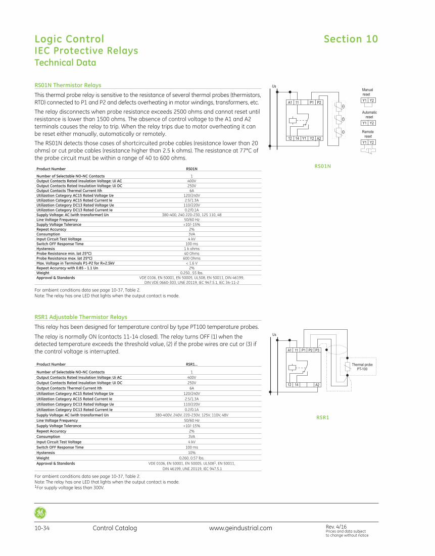
RSR1 Adjustable Thermistor Relays
This relay has been designed for temperature control by type PT100 temperature probes.
The relay is normally ON (contacts 11-14 closed). The relay turns OFF (1) when thedetected temperature exceeds the threshold value, (2) if the probe wires are cut or (3) ifthe control voltage is interrupted.
RSR1
Product Number RSR1…
Number of Selectable NO-NC Contacts 1 Output Contacts Rated Insulation Voltage: Ui AC 400V Output Contacts Rated Insulation Voltage: Ui DC 250V Output Contacts Thermal Current Ith 6A Utilization Category AC15 Rated Voltage Ue 120/240V Utilization Category AC15 Rated Current Ie 2.5/1.3A Utilization Category DC13 Rated Voltage Ue 110/220V Utilization Category DC13 Rated Current Ie 0.2/0.1A Supply Voltage: AC (with transformer) Un 380-400V, 240V, 220-230V, 125V, 110V, 48V Line Voltage Frequency 50/60 Hz Supply Voltage Tolerance +10/-15% Repeat Accuracy 2% Consumption 3VA Input Circuit Test Voltage 4 kV Switch OFF Response Time 100 ms Hysteresis 10% Weight 0.260, 0.57 lbs. Approval & Standards VDE 0106, EN 50001, EN 50005, UL5081, EN 50011, DIN 46199, UNE 20119, IEC 947.5.1
For ambient conditions data see page 10-37, Table 2.Note: The relay has one LED that lights when the output contact is made.1For supply voltage less than 300V.
Technical Data
RS01N Thermistor Relays
This thermal probe relay is sensitive to the resistance of several thermal probes (thermistors,RTD) connected to P1 and P2 and defects overheating in motor windings, transformers, etc.
The relay disconnects when probe resistance exceeds 2500 ohms and cannot reset untilresistance is lower than 1500 ohms. The absence of control voltage to the A1 and A2terminals causes the relay to trip. When the relay trips due to motor overheating it canbe reset either manually, automatically or remotely.
The RS01N detects those cases of shortcircuited probe cables (resistance lower than 20ohms) or cut probe cables (resistance higher than 2.5 k ohms). The resistance at 77°C ofthe probe circuit must be within a range of 40 to 600 ohms.
RS01N Product Number RS01N
Number of Selectable NO-NC Contacts 1 Output Contacts Rated Insulation Voltage: Ui AC 400V Output Contacts Rated Insulation Voltage: Ui DC 250V Output Contacts Thermal Current Ith 6A Utilization Category AC15 Rated Voltage Ue 120/240V Utilization Category AC15 Rated Current Ie 2.5/1.3A Utilization Category DC13 Rated Voltage Ue 110/220V Utilization Category DC13 Rated Current Ie 0.2/0.1A Supply Voltage: AC (with transformer) Un 380-400, 240 220-230, 125 110, 48 Line Voltage Frequency 50/60 Hz Supply Voltage Tolerance +10/-15% Repeat Accuracy 2% Consumption 3VA Input Circuit Test Voltage 4 kV Switch OFF Response Time 100 ms Hysteresis 1 k ohms Probe Resistance min. (at 25°C) 40 Ohms Probe Resistance max. (at 25°C) 600 Ohms Max. Voltage in Terminals P1-P2 for R=2.5kV < 1.6 V Repeat Accuracy with 0.85 - 1.1 Un 2% Weight 0.250, .55 lbs. Approval & Standards VDE 0106, EN 50001, EN 50005, UL508, EN 50011, DIN 46199, DIN VDE 0660-303, UNE 20119, IEC 947.5.1, IEC 34-11-2
For ambient conditions data see page 10-37, Table 2.Note: The relay has one LED that lights when the output contact is made.
Section 10Logic ControlIEC Protective Relays
10-34 Control Catalog Rev. 4/16Prices and data subject to change without notice
www.geindustrial.com
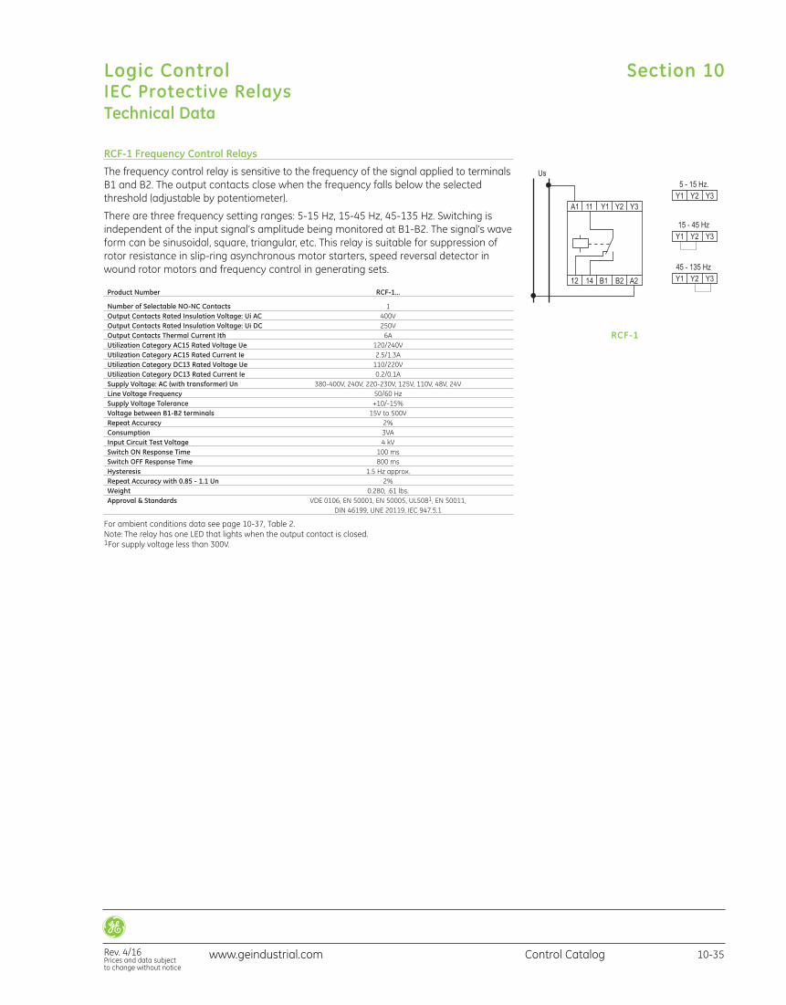
RCF-1 Frequency Control Relays
The frequency control relay is sensitive to the frequency of the signal applied to terminalsB1 and B2. The output contacts close when the frequency falls below the selectedthreshold (adjustable by potentiometer).
There are three frequency setting ranges: 5-15 Hz, 15-45 Hz, 45-135 Hz. Switching isindependent of the input signal’s amplitude being monitored at B1-B2. The signal’s waveform can be sinusoidal, square, triangular, etc. This relay is suitable for suppression ofrotor resistance in slip-ring asynchronous motor starters, speed reversal detector inwound rotor motors and frequency control in generating sets.
RCF-1
Product Number RCF-1…
Number of Selectable NO-NC Contacts 1 Output Contacts Rated Insulation Voltage: Ui AC 400V Output Contacts Rated Insulation Voltage: Ui DC 250V Output Contacts Thermal Current Ith 6A Utilization Category AC15 Rated Voltage Ue 120/240V Utilization Category AC15 Rated Current Ie 2.5/1.3A Utilization Category DC13 Rated Voltage Ue 110/220V Utilization Category DC13 Rated Current Ie 0.2/0.1A Supply Voltage: AC (with transformer) Un 380-400V, 240V, 220-230V, 125V, 110V, 48V, 24V Line Voltage Frequency 50/60 Hz Supply Voltage Tolerance +10/-15% Voltage between B1-B2 terminals 15V to 500V Repeat Accuracy 2% Consumption 3VA Input Circuit Test Voltage 4 kV Switch ON Response Time 100 ms Switch OFF Response Time 800 ms Hysteresis 1.5 Hz approx. Repeat Accuracy with 0.85 - 1.1 Un 2% Weight 0.280, .61 lbs. Approval & Standards VDE 0106, EN 50001, EN 50005, UL5081, EN 50011, DIN 46199, UNE 20119, IEC 947.5.1
For ambient conditions data see page 10-37, Table 2.Note: The relay has one LED that lights when the output contact is closed.1For supply voltage less than 300V.
Technical Data
Section 10
Rev. 4/16Prices and data subject to change without notice
Logic ControlIEC Protective Relays
10-35Control Catalogwww.geindustrial.com
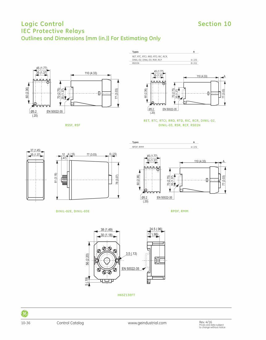
RSSF, RSFRET, RTC, RTCI, RRD, RTD, RIC, RCR, DINIL-02,
DINIL-03, RSR, RCF, RS01N
Types A
RET, RTC, RTCI, RRD, RTD, RIC, RCR, DINIL-02, DINIL-03, RSR, RCF 4 (.15) RS01N 8 (.31)
DINIL-02E, DINIL-03E RPDF, RMM
Types A
RPDF, RMM 4 (.15)
H6SZ13EFT
Outlines and Dimensions [mm (in.)] For Estimating Only
Section 10Logic ControlIEC Protective Relays
10-36 Control Catalog Rev. 4/16Prices and data subject to change without notice
www.geindustrial.com
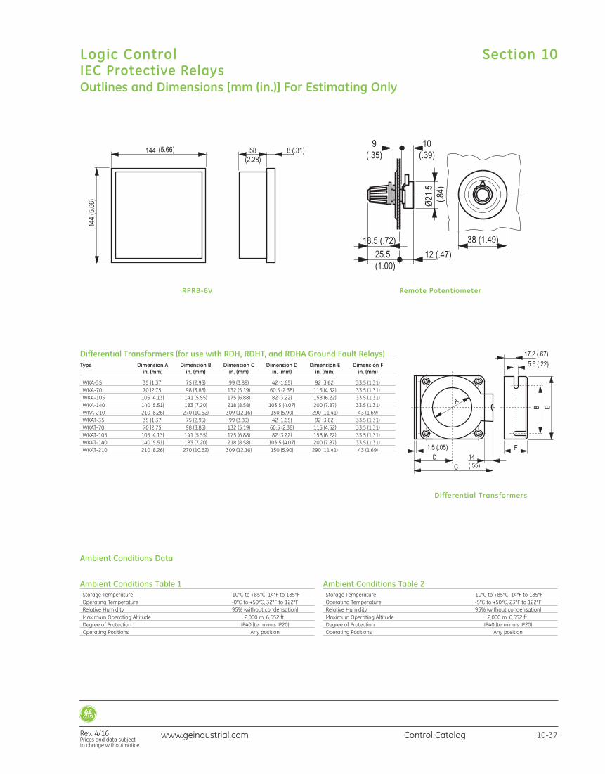
Differential Transformers
Differential Transformers (for use with RDH, RDHT, and RDHA Ground Fault Relays)Type Dimension A Dimension B Dimension C Dimension D Dimension E Dimension F in. (mm) in. (mm) in. (mm) in. (mm) in. (mm) in. (mm)
WKA-35 35 (1.37) 75 (2.95) 99 (3.89) 42 (1.65) 92 (3.62) 33.5 (1.31) WKA-70 70 (2.75) 98 (3.85) 132 (5.19) 60.5 (2.38) 115 (4.52) 33.5 (1.31) WKA-105 105 (4.13) 141 (5.55) 175 (6.88) 82 (3.22) 158 (6.22) 33.5 (1.31) WKA-140 140 (5.51) 183 (7.20) 218 (8.58) 103.5 (4.07) 200 (7.87) 33.5 (1.31) WKA-210 210 (8.26) 270 (10.62) 309 (12.16) 150 (5.90) 290 (11.41) 43 (1.69) WKAT-35 35 (1.37) 75 (2.95) 99 (3.89) 42 (1.65) 92 (3.62) 33.5 (1.31) WKAT-70 70 (2.75) 98 (3.85) 132 (5.19) 60.5 (2.38) 115 (4.52) 33.5 (1.31) WKAT-105 105 (4.13) 141 (5.55) 175 (6.88) 82 (3.22) 158 (6.22) 33.5 (1.31) WKAT-140 140 (5.51) 183 (7.20) 218 (8.58) 103.5 (4.07) 200 (7.87) 33.5 (1.31) WKAT-210 210 (8.26) 270 (10.62) 309 (12.16) 150 (5.90) 290 (11.41) 43 (1.69)
RPRB-6V Remote Potentiometer
Ambient Conditions Table 1 Storage Temperature -10°C to +85°C, 14°F to 185°F Operating Temperature -0°C to +50°C, 32°F to 122°F Relative Humidity 95% (without condensation) Maximum Operating Altitude 2,000 m, 6,652 ft. Degree of Protection IP40 (terminals IP20) Operating Positions Any position
Ambient Conditions Table 2 Storage Temperature -10°C to +85°C, 14°F to 185°F Operating Temperature -5°C to +50°C, 23°F to 122°F Relative Humidity 95% (without condensation) Maximum Operating Altitude 2,000 m, 6,652 ft. Degree of Protection IP40 (terminals IP20) Operating Positions Any position
Ambient Conditions Data
Outlines and Dimensions [mm (in.)] For Estimating Only
Section 10
Rev. 4/16Prices and data subject to change without notice
Logic ControlIEC Protective Relays
10-37Control Catalogwww.geindustrial.com
www.geindustrial.com Rev. 4/16Prices and data subject to change without notice
Control Catalog10-38
Logic Control Section 10
NOTES: