todd stockert ieee northcon 2002 october 23, 2002 [email protected][email protected]...
Post on 21-Dec-2015
215 views
TRANSCRIPT

Todd StockertIEEE Northcon 2002October 23, 2002 [email protected]
Physical Layer and RF Testing Overview of Wireless LAN MODEMS

Physical Layer and RF Testing Overview if Wireless LAN MODEMS23 October, 2002
Copyright Agilent Technologies 2002 Page 2
For more and updated information…Agilent WLAN & Bluetooth Links:
WLAN & Bluetooth Information
http://www.agilent.com/find/wlan
WLAN & Bluetooth Webcasts & Courses
http://www.get.agilent.com/bluetooth/mi/wc.shtml
WLAN & Bluetooth Resource Library
http://www.get.agilent.com/bluetooth/mi/library.shtml

Physical Layer and RF Testing Overview if Wireless LAN MODEMS23 October, 2002
Copyright Agilent Technologies 2002 Page 3
WLAN: What and Why
WHAT? • An extension to, or a replacement for, wired LANs that offers:
• Ease of installation• Flexibility• Scalability• Cost savings• Mobility
WHY?• Eliminate physical constraints of wires• Installing wires is expensive, time consuming, and disruptive
Physical Layer and RF Testing Overview if Wireless LAN MODEMS23 October, 2002
Copyright Agilent Technologies 2002 Page 4
Topics
• Introduction to Wireless LAN Standards
• 802.11b PHYsical layer
• Overview of Spread Spectrum modulation
• 802.11b PPDU Structure
• 802.11a PHYsical layer
• Overview of OFDM
• 802.11a PPDU Structure
• Glance at 802.11g (Draft standard)
• Overview of WLAN Testing and Specification Measurements

Physical Layer and RF Testing Overview if Wireless LAN MODEMS23 October, 2002
Copyright Agilent Technologies 2002 Page 5
Current WLAN Standards
Approved Standard Throughput
1996 ETSI HIPERLAN/ I 1.47, 23.5 MBit/ sec
1997 IEEE 802.11 1, 2 MBit/ sec
1999 IEEE 802.11b 1, 2, 5.5, 11MBit/ sec
1999 IEEE 802.11a 6 - 54 MBit/ sec
2000 ETSI HIPERLAN/ II 6 - 54 MBit/ sec
2002? IEEE 802.11g 1 - 54 MBit/ sec

Physical Layer and RF Testing Overview if Wireless LAN MODEMS23 October, 2002
Copyright Agilent Technologies 2002 Page 6
IEEE 802.11b• Incorporates 802.11 1,2 Mbit/sec modes, adds
5.5 and 11 Mbit/sec modes
• Most successful WLAN standard to date
• “Wi-Fi” standard
• 2.4GHz ISM frequency band

Physical Layer and RF Testing Overview if Wireless LAN MODEMS23 October, 2002
Copyright Agilent Technologies 2002 Page 7
IEEE 802.11b: 2.4GHz Difficulties
802.11b Burst
uWave Ovens
Discrete Tone
uWave OvenSplatter
FHSS(Cordless Phone, Bluetooth...)

Physical Layer and RF Testing Overview if Wireless LAN MODEMS23 October, 2002
Copyright Agilent Technologies 2002 Page 8
802.11B: Modulation Formats• All modes incorporate “Spread Spectrum” modulation
• 802.11b extends 802.11 data rates to include 5.5 and 11 MBit/sec
• There are three rates to keep track of:Chip Rate: 11 MChip/sec -- always
Bit Rates: 1 MBit/sec DBPSK 11 chip Barker sequence
2 MBit/sec DQPSK 11 chip Barker sequence 5.5 MBit/sec QPSK, 4 8-chip CCK spreading 11 MBit/sec DQPSK, 64 8-chip CCK spreading
5.5 MBit/sec BPSK PBCC (optional) 11 Mbit/sec QPSK PBCC (optional)
Symbol Rates: 1 MHz (11/11) and 1.375 MHz (11/8)
• At all rates, the signal looks like an 11 MHz BPSK or QPSK waveform

Physical Layer and RF Testing Overview if Wireless LAN MODEMS23 October, 2002
Copyright Agilent Technologies 2002 Page 9
Spread Spectrum Concepts: Simple Spreading 802.11B -- 1 MBit/Sec
Map
Barker Sequence+1, –1, +1, +1, –1, +1, +1, +1, –1, –1, –1
1 Bit In
Data Phase Change(deg)
0 01 180
DBPSKFor each single input bit, there are two possible 11 chip sequences that can be transmitted
+1, –1, +1, +1, –1, +1, +1, +1, –1, –1, –1–1, +1, –1, –1, +1, –1, –1, –1, +1, +1, +1
One sequence is simply the inverse of the other
11 Complex Chips Out

Physical Layer and RF Testing Overview if Wireless LAN MODEMS23 October, 2002
Copyright Agilent Technologies 2002 Page 10
Spread Spectrum Concepts: Simple Spreading 802.11B -- 2 MBit/Sec
Map
Barker Sequence+1, –1, +1, +1, –1, +1, +1, +1, –1, –1, –1
2 Bits In
For every two input bits, there are four possible 11 chip sequences that can be transmitted
+1, –1, +1, +1, –1, +1, +1, +1, –1, –1, –1+j, –j, +j, +j, –j, +j, +j, +j, –j, –j, –j–1, +1, –1, –1, +1, –1, – 1, –1, +1, +1, +1–j, +j, –j, –j, +j, –j, – j, –j, +j, +j, +j
11 Complex Chips Out
Data (Dibit) Phase Change (deg)
00 0
01 9011 18010 -90
DQPSK

Physical Layer and RF Testing Overview if Wireless LAN MODEMS23 October, 2002
Copyright Agilent Technologies 2002 Page 11
802.11B -- 11 MBit/Sec ??
Map
Barker Sequence+1, –1, +1, +1, –1, +1, +1, +1, –1, –1, –1
11 Bits In
11 Complex Chips Out
D2048PSK?

Physical Layer and RF Testing Overview if Wireless LAN MODEMS23 October, 2002
Copyright Agilent Technologies 2002 Page 12
Spread Spectrum Concepts: Simple Spreading 802.11B -- 5.5 and 11 MBit/Sec
4 Bits In
1 of 4 8-chip sequence
Selector
DQPSKRotate
8 Complex Chips Out
8 Bits In
1 of 64 8-chip sequence
Selector
DQPSKRotate
8 Complex Chips Out
d0-d3d0,d1
d2-d7
d0-d7
d0,d1
d2,d3
Physical Layer and RF Testing Overview if Wireless LAN MODEMS23 October, 2002
Copyright Agilent Technologies 2002 Page 13
IEEE 802 Protocol Acronyms
*From Agilent 802.11b WLAN Signal Studio Software Product Note
Physical Medium Dependent(PMD)
PHY Convergence Layer Procedure(PLCP)
MAC sublayer Protocol Data Units (MPDU)
PHY Protocol Data Units (PPDU)
PLCP Service Data Units (PSDU).
*See IEEE802 standards for more detail

Physical Layer and RF Testing Overview if Wireless LAN MODEMS23 October, 2002
Copyright Agilent Technologies 2002 Page 14
802.11B: Long PLCP PPDU Format
*From Agilent 802.11b WLAN Signal Studio Software Product Note

Physical Layer and RF Testing Overview if Wireless LAN MODEMS23 October, 2002
Copyright Agilent Technologies 2002 Page 15
Structure of IEEE802.11b CCK Frame (= Burst)PLCP Preamble PSDUPLCP Header
144 bits Fn(LENGTH,SIGNAL) bits48 bits

Physical Layer and RF Testing Overview if Wireless LAN MODEMS23 October, 2002
Copyright Agilent Technologies 2002 Page 16
Structure of IEEE802.11b CCK Frame (= Burst)PLCP Preamble PSDUPLCP Header
PLCP Preamble• 144 usec, (72 for ShortPLCP)• 1MBit/s modulation• Scrambled 1’s + SFD• Signal detect, AGC,timing synchronization,frequency estimation.

Physical Layer and RF Testing Overview if Wireless LAN MODEMS23 October, 2002
Copyright Agilent Technologies 2002 Page 17
Structure of IEEE802.11b CCK Frame (= Burst)PLCP Preamble PSDUPLCP Header
PLCP Header•1MBit/s modulation (2MBit/s for ShortPLCP)•CCITT CRC-16 Protects these fields
SIGNAL
- - b2b3 - - - b7SERVICE
b2: Locked clocks 0: Not Locked 1: Lockedb3: Modulation Selection 0:CCK 1:PBCCb7: Length extension bit Solves LENGTH ambiguity
0x0A 1Mbps0x14 2Mbps0x37 5.5Mbps0x6E 11 Mbps
LENGTH
16bit Length of PSDU in µsec (Special Rounding)

Physical Layer and RF Testing Overview if Wireless LAN MODEMS23 October, 2002
Copyright Agilent Technologies 2002 Page 18
Structure of IEEE802.11b CCK Frame (= Burst)PLCP Preamble PSDUPLCP Header
PSDU• Format varies with data rate• Max symbols varies with data rate• MAC layer starts here.
•MAC Header•Payload Data•FCS

Physical Layer and RF Testing Overview if Wireless LAN MODEMS23 October, 2002
Copyright Agilent Technologies 2002 Page 19
802.11B: Short PLCP PPDU Format (Optional)
*From Agilent 802.11b WLAN Signal Studio Software Product Note

Physical Layer and RF Testing Overview if Wireless LAN MODEMS23 October, 2002
Copyright Agilent Technologies 2002 Page 20
Significant differences from 802.11b
• 5-6 GHz Frequency Bands (Less interference, more spectrum)
• OFDM Modulation
• 54 MBits/Sec in the same bandwidth
RF Characteristics
• More precise RF design (<1/2 the wavelength)
• Much Higher Peak-to-Average Power Ratio
• More Sensitive to Phase Noise
IEEE 802.11a

Physical Layer and RF Testing Overview if Wireless LAN MODEMS23 October, 2002
Copyright Agilent Technologies 2002 Page 21
OFDM – Basic Concepts
• Slower symbol rate x multiple carriers = similar bits/sec/Hz
• Carrier spacing creates orthogonality.
• Less susceptible to:- single freq.
interference- multipath
dropouts- impulse noise
• IEEE 802.11a and HiperLAN/2
- 52 carriers- 250 kHz symbol
rate- 312.5 kHz
spacing- 18 MHz
bandwidth
. . . . . .

Physical Layer and RF Testing Overview if Wireless LAN MODEMS23 October, 2002
Copyright Agilent Technologies 2002 Page 22
Generating OFDM
-2 +2
+1
0-1-3 +3.. ..-24
-25
+25
+26
+24
....-26
carrier number:
bits
encode, interleave,map onto
constellationload complex values
into frequency bins.29 + j.85
1011
do inverse FFT tocreate time waveform
add guard interval,clock out at 20
MSa/sectransmit as 1
symbol
repeat 52 times
repeat untildata
finished

Physical Layer and RF Testing Overview if Wireless LAN MODEMS23 October, 2002
Copyright Agilent Technologies 2002 Page 23
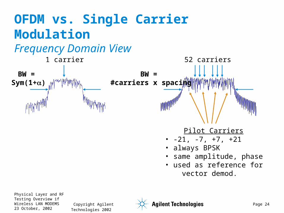
OFDM vs. Single Carrier ModulationFrequency Domain View
1 carrier 52 carriers
BW = Sym(1+)
BW = #carriers x spacing
Adj Chan =Distortion
Adj Chan =Normal Rolloff
Carrier #0 always null
Physical Layer and RF Testing Overview if Wireless LAN MODEMS23 October, 2002
Copyright Agilent Technologies 2002 Page 24
OFDM vs. Single Carrier ModulationFrequency Domain View
1 carrier 52 carriers
BW = Sym(1+)
BW = #carriers x spacing
Pilot Carriers• -21, -7, +7, +21• always BPSK• same amplitude, phase• used as reference for vector demod.

Physical Layer and RF Testing Overview if Wireless LAN MODEMS23 October, 2002
Copyright Agilent Technologies 2002 Page 25
OFDM vs. Single Carrier ModulationTime Domain View
Data rate = 54 Mbits/sec @ ¾ coding = 72 Mbits/sec @ 64QAM = 12 MSym/sec
1 symbol = one point in time1 point in time = 1 symbol
SCM: OFDM:
Data rate = 54 Mbits/sec @ ¾ coding = 72 Mbits/sec @ 48 carriers= 1.5 Mbits/sec @ 64QAM = 250 kSym/sec1 symbol = 1 point in frequency and time1 point in time = ~meaningless
1 Sym = .083 usec 1 Sym = 4.0 usec
This is a sample;FFT(64 samples) gives64 freq bins (48 carriers + 4 pilots + 12 zeros)
This is a symbol = 6 bits

Physical Layer and RF Testing Overview if Wireless LAN MODEMS23 October, 2002
Copyright Agilent Technologies 2002 Page 26
Structure of IEEE802.11a OFDM Frame (= Burst)
Short Training …Data NSIGNALData 1 Data 2Chan. Estimation
8 4 4 4 4 usec. . .
8

Physical Layer and RF Testing Overview if Wireless LAN MODEMS23 October, 2002
Copyright Agilent Technologies 2002 Page 27
Structure of IEEE802.11a OFDM Frame (= Burst)
Short Training …Data NSIGNALData 1 Data 2Chan. Estimation
Short Training Seq.• 8 uSec length• Every 4th carrier,equal amplitude/phase• Signal detect, AGC,timing synchronization,coarse freq. estimation.
. . .

Physical Layer and RF Testing Overview if Wireless LAN MODEMS23 October, 2002
Copyright Agilent Technologies 2002 Page 28
Structure of IEEE802.11a OFDM Frame (= Burst)
Short Training …Data NSIGNALData 1 Data 2Chan. Estimation
Channel Estimation• 8 uSec length• Every carrier, equalamplitude and phase.• Channel equalization,fine freq. estimation.
. . .

Physical Layer and RF Testing Overview if Wireless LAN MODEMS23 October, 2002
Copyright Agilent Technologies 2002 Page 29
Structure of IEEE802.11a OFDM Frame (= Burst)
Short Training …Data NSIGNALData 1 Data 2Chan. Estimation
SIGNAL Symbol• 4 uSec length• Always BPSK.• Describes this frame’s rate, length.
These parametersare read from signalunder test.
. . .

Physical Layer and RF Testing Overview if Wireless LAN MODEMS23 October, 2002
Copyright Agilent Technologies 2002 Page 30
Structure of IEEE802.11a OFDM Frame (= Burst)
Short Training …Data NSIGNALData 1 Data 2Chan. Estimation
Data Symbols• 1 symbol = 4 uSec length 1 FFT 52 carriers (48 + 4) 52 constellation dots• Format varies• Coding varies• Max 4096 octetsper frame.• MAC layer starts here.3/4
2/3
3/4
1/2
3/4
1/2
3/4
1/2
Coding Rate
216
192
144
96
72
48
36
24
Bits per Symbol
Mod. Format
Data Rate
64QAM54
64QAM48
16QAM36
16QAM24
QPSK18
QPSK12
BPSK9
BPSK6 Mbits/sec
= 48 x 6 x .75
. . .

Physical Layer and RF Testing Overview if Wireless LAN MODEMS23 October, 2002
Copyright Agilent Technologies 2002 Page 31
IEEE 802.11a Payload Structure
Address 4Address 2Address 3SequenceControlAddress 1Frame
ControlDuration/
ID
Frame ChkSequenceUser DataTail Bits Pad Bits
2 2 6 6 6 2 6 bytes
40-4061 bytes
MAC Header
. . .
. . .

Physical Layer and RF Testing Overview if Wireless LAN MODEMS23 October, 2002
Copyright Agilent Technologies 2002 Page 32
IEEE802.11a versus HiperLAN/2
Similarities:• 5-6 GHz frequencies• 18 MHz bandwidth• 52 subcarriers• 250 kHz symbol rate• BPSK, QPSK, 16/64QAM• 6-54 MB/sec
Differences:• More choice of data services• Preamble contents• MAC contents• Sync procedure• Length of Guard Interval

Physical Layer and RF Testing Overview if Wireless LAN MODEMS23 October, 2002
Copyright Agilent Technologies 2002 Page 33
IEEE 802.11g• Mandatory:
• All mandatory 802.11b modes
• 802.11b ShortPLCP packet format
• All mandatory 802.11a modes using 802.11b channels
• Goals:
• Puts 802.11a rates into 2.4GHz band
• Creates 1-54 Mbit/sec variable rate WLAN standard
• Completely backward compatible to 802.11b
• Many implementation choices
CCK-OFDM, PBCC-22, PBCC-33

Physical Layer and RF Testing Overview if Wireless LAN MODEMS23 October, 2002
Copyright Agilent Technologies 2002 Page 34
802.11G: Rates and ModulationType Rates (MBit/ sec) Modulation Type Specified
802.11b Mandatory 1, 2, 5.5, 11 DBPSK-Barker,DQPSK-Barker, CCK
Mandatory
802.11b Optional 5.5, 11 PBCC Optional
802.11a Mandatory 6, 12, 24 OFDM Mandatory
802.11a Optional 9, 18, 36, 48, 54 OFDM Optional
CCK-OFDM 6, 12, 24 OFDM + 802.11bPreamble
Optional
CCK-OFDM Optional 9, 18, 36, 48, 54 OFDM + 802.11bPreamble
Optional
PBCC-22 22 PBCC-22 (8PSK) Optional
PBCC-33 33 PBCC-33 (8PSK) Optional

Physical Layer and RF Testing Overview if Wireless LAN MODEMS23 October, 2002
Copyright Agilent Technologies 2002 Page 35
802.11G: Draft CCK-OFDM Packet formats
Long PLCP PPDU Packet
Short PLCP PPDU Packet
LongPLCP
OFDM LONG SYNCOFDM SIGNALOFDM PSDUSignal Extension
PSDU
8 µsec 8 µsec Nsym x 4 µsec 6 µsec
192 µsec
ShortPLCP
OFDM LONG SYNCOFDM SIGNALOFDM PSDUSignal Extension
PSDU
8 µsec 8 µsec Nsym x 4 µsec 6 µsec
96 µsec
Physical Layer and RF Testing Overview if Wireless LAN MODEMS23 October, 2002
Copyright Agilent Technologies 2002 Page 36
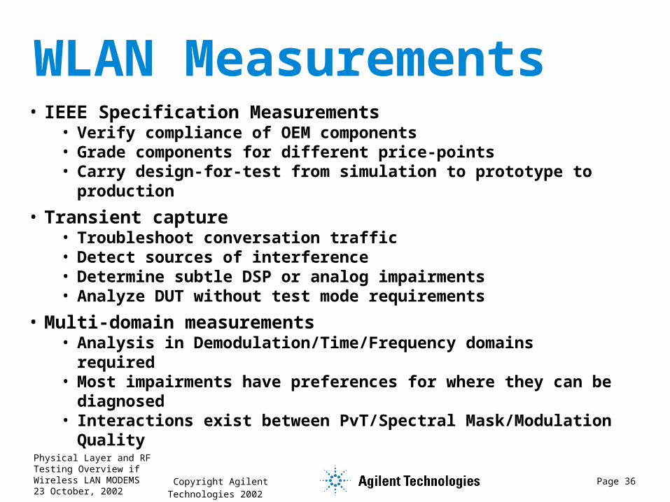
WLAN Measurements• IEEE Specification Measurements
• Verify compliance of OEM components• Grade components for different price-points• Carry design-for-test from simulation to prototype to
production
• Transient capture• Troubleshoot conversation traffic• Detect sources of interference• Determine subtle DSP or analog impairments• Analyze DUT without test mode requirements
• Multi-domain measurements• Analysis in Demodulation/Time/Frequency domains
required• Most impairments have preferences for where they can
be diagnosed• Interactions exist between PvT/Spectral
Mask/Modulation Quality

Physical Layer and RF Testing Overview if Wireless LAN MODEMS23 October, 2002
Copyright Agilent Technologies 2002 Page 37
IEEE802.11b Transmitter Testing
Measurement Specified by the 802.11B Standard
18.4.6.8 – TX spurious
18.4.7.1 – TX power level
18.4.7.3 – TX spectrum mask
18.4.7.4 – TX center freq. tolerance
18.4.7.5 – Symbol clock freq. tolerance
18.4.7.6 – TX power-time mask
18.4.7.7 – TX carrier leakage
18.4.7.8 – TX modulation accuracy

Physical Layer and RF Testing Overview if Wireless LAN MODEMS23 October, 2002
Copyright Agilent Technologies 2002 Page 38
802.11B: TX Spectral Mask

Physical Layer and RF Testing Overview if Wireless LAN MODEMS23 October, 2002
Copyright Agilent Technologies 2002 Page 39
802.11B: TX power-time mask : Power-Up Ramp
2 usec

Physical Layer and RF Testing Overview if Wireless LAN MODEMS23 October, 2002
Copyright Agilent Technologies 2002 Page 40
802.11B: Power-Down Ramp

Physical Layer and RF Testing Overview if Wireless LAN MODEMS23 October, 2002
Copyright Agilent Technologies 2002 Page 41
EVM: A Model For Signal Errors
Ideal Signal Generator
Error Signal Generator(e.g. noise, distortion, spurious, phase noise)
Transmitter
Ideal(t)
error(t)
actual(t)
Ideal(t)Act
ual(t
) Error(t)
Magnitude Error(t)
Error Vector Magnitude(t)
Phase Error(t)I
Q
Carrier Leakage

Physical Layer and RF Testing Overview if Wireless LAN MODEMS23 October, 2002
Copyright Agilent Technologies 2002 Page 42
IEEE802.11b Modulation Accuracy
1000..1:35.0))(( nnVMax err
Physical Layer and RF Testing Overview if Wireless LAN MODEMS23 October, 2002
Copyright Agilent Technologies 2002 Page 43
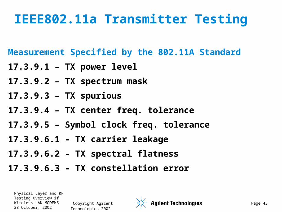
IEEE802.11a Transmitter Testing
Measurement Specified by the 802.11A Standard
17.3.9.1 – TX power level
17.3.9.2 – TX spectrum mask
17.3.9.3 – TX spurious
17.3.9.4 – TX center freq. tolerance
17.3.9.5 – Symbol clock freq. tolerance
17.3.9.6.1 – TX carrier leakage
17.3.9.6.2 – TX spectral flatness
17.3.9.6.3 – TX constellation error

Physical Layer and RF Testing Overview if Wireless LAN MODEMS23 October, 2002
Copyright Agilent Technologies 2002 Page 44
802.11A: Measuring Center Frequency Leakage With Time Gating, Band Power, C/N Marker
Time Gating selects justthe short sync sequence.
Band Power measures powerduring the short sync.
C/N marker computes leakage at carrier #zero.

Physical Layer and RF Testing Overview if Wireless LAN MODEMS23 October, 2002
Copyright Agilent Technologies 2002 Page 45
802.11A: Measuring Modulation Quality

Physical Layer and RF Testing Overview if Wireless LAN MODEMS23 October, 2002
Copyright Agilent Technologies 2002 Page 46
802.11A: Modulation Quality
Data Rate (Mbit/sec) Relative Constellation Error (dB) EVM (%RMS)6 -5 56.29 -8 39.8
12 -10 31.618 -13 22.324 -16 15.836 -19 11.248 -22 7.954 -25 5.6
Physical Layer and RF Testing Overview if Wireless LAN MODEMS23 October, 2002
Copyright Agilent Technologies 2002 Page 47
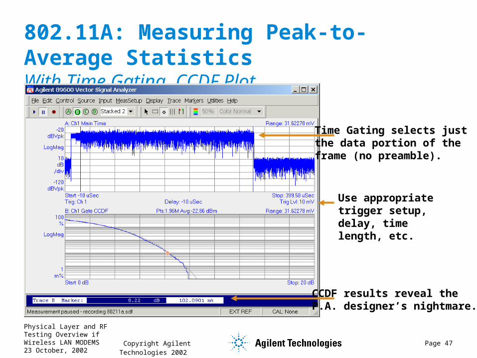
802.11A: Measuring Peak-to-Average StatisticsWith Time Gating, CCDF Plot
CCDF results reveal the P.A. designer’s nightmare.
Time Gating selects justthe data portion of theframe (no preamble).
Use appropriate trigger setup, delay, time length, etc.

Physical Layer and RF Testing Overview if Wireless LAN MODEMS23 October, 2002
Copyright Agilent Technologies 2002 Page 48
802.11A: Channel Freq Response (Spectral Flatness)Equalizer-based
Display as Amplitude Response,Phase Response,Impulse Response,or Group Delay.

Physical Layer and RF Testing Overview if Wireless LAN MODEMS23 October, 2002
Copyright Agilent Technologies 2002 Page 49
802.11A: Transmit Spectral Mask

Physical Layer and RF Testing Overview if Wireless LAN MODEMS23 October, 2002
Copyright Agilent Technologies 2002 Page 50
IEEE802.11 Receiver TestingMeasurement Specified by the 802.11A Standard (Packet Error Ratio (PER) testing)
•17.3.10.1 Receiver minimum input level sensitivity•17.3.10.2 Receiver adjacent channel rejection•17.3.10.3 Receiver non-adjacent channel rejection•17.3.10.4 Receiver maximum input level
Measurements for Receiver Troubleshooting•Quality of the test signal used for RX Sensitivity Testing•Receiver Spurious•Receiver Phase Noise•Receiver EVM (distortion, noise, etc)•Measurements at RF, IF and IQ Baseband
Measurement Specified by the 802.11B Standard (Frame Error Ratio (FER) testing)
•18.4.8.1 Receiver minimum input level sensitivity•18.4.8.2 Receiver maximum input level•18.4.8.3 Receiver adjacent channel rejection
Physical Layer and RF Testing Overview if Wireless LAN MODEMS23 October, 2002
Copyright Agilent Technologies 2002 Page 51
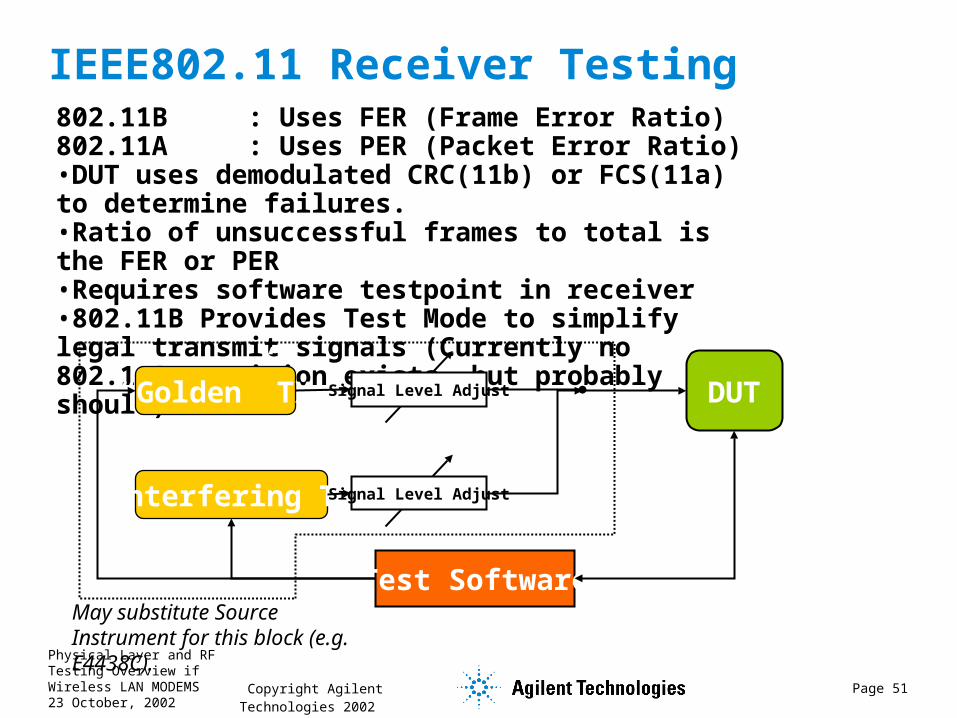
IEEE802.11 Receiver Testing802.11B : Uses FER (Frame Error Ratio)802.11A : Uses PER (Packet Error Ratio)•DUT uses demodulated CRC(11b) or FCS(11a) to determine failures.•Ratio of unsuccessful frames to total is the FER or PER•Requires software testpoint in receiver•802.11B Provides Test Mode to simplify legal transmit signals (Currently no 802.11A provision exists, but probably should).
“Golden” TX Signal Level Adjust
Interfering TX
DUT
Test Software
Signal Level Adjust
May substitute Source Instrument for this block (e.g. E4438C).

Physical Layer and RF Testing Overview if Wireless LAN MODEMS23 October, 2002
Copyright Agilent Technologies 2002 Page 52
Summary• Wireless LAN Standards - Interoperability is
key to success. IEEE 802.11 standards are leading the way.
• 802.11b PHY
• Described the mandatory Spread Spectrum modulation formats
• Explored the 802.11b PHY packet structure
• 802.11a PHY
• Described some details about OFDM modulation
• Explored the 802.11a PHY packet structure
• Took a glance at 802.11g (Draft standard)
• Discussed WLAN testing methods and 802.11b/a Specification measurements

Physical Layer and RF Testing Overview if Wireless LAN MODEMS23 October, 2002
Copyright Agilent Technologies 2002 Page 53
WLAN Measurement Setup