original instructions - agilent.com · v labware minihub safety and installation guide preface this...
TRANSCRIPT

Labware MiniHub
Safety and Installation GuideOriginal instructions

Notices© Agilent Technologies, Inc. 2015
No part of this manual may be reproduced in any form or by any means (including electronic storage and retrieval or translation into a foreign language) without prior agreement and written consent from Agilent Technologies, Inc. as governed by United States and international copyright laws.
User Guide Part Number
G5471-90004
Edition
Revision B, June 2015
Contact Information
Agilent Technologies Inc. Automation Solutions 5301 Stevens Creek Blvd. Santa Clara, CA 95051 USA
Technical Support: 1.800.979.4811 or +1.408.345.8011 [email protected]
Customer Service: 1.866.428.9811 or +1.408.345.8356 [email protected]
European Service: +44 (0) 8457125292 [email protected]
Documentation feedback: [email protected]
Web: www.agilent.com/lifesciences/ automation
Acknowledgements
Microsoft and Windows are registered trademarks of the Microsoft Corporation in the United States and other countries.
Adobe and Acrobat are trademarks of Adobe Systems Incorporated.
Warranty
The material contained in this docu-ment is provided “as is,” and is sub-ject to being changed, without notice, in future editions. Further, to the max-imum extent permitted by applicable law, Agilent disclaims all warranties, either express or implied, with regard to this manual and any information contained herein, including but not limited to the implied warranties of merchantability and fitness for a par-ticular purpose. Agilent shall not be liable for errors or for incidental or consequential damages in connection with the furnishing, use, or perfor-mance of this document or of any information contained herein. Should Agilent and the user have a separate written agreement with warranty terms covering the material in this document that conflict with these terms, the warranty terms in the sep-arate agreement shall control.
Technology Licenses
The hardware and/or software described in this document are furnished under a license and may be used or copied only in accordance with the terms of such license.
Restricted Rights Legend
If software is for use in the performance of a U.S. Government prime contract or sub-contract, Software is delivered and licensed as “Commercial computer soft-ware” as defined in DFAR 252.227-7014 (June 1995), or as a “commercial item” as defined in FAR 2.101(a) or as “Restricted computer software” as defined in FAR 52.227-19 (June 1987) or any equivalent agency regulation or contract clause. Use, duplication or disclosure of Software is subject to Agilent Technologies’ standard commercial license terms, and non-DOD Departments and Agencies of the U.S. Gov-ernment will receive no greater than Restricted Rights as defined in FAR 52.227-19(c)(1-2) (June 1987). U.S. Government users will receive no greater than Limited Rights as defined in FAR 52.227-14
(June1987) or DFAR 252.227-7015 (b)(2) (November 1995), as applicable in any technical data.
Safety Notices
A WARNING notice denotes a hazard. It calls attention to an operating procedure, practice, or the like that, if not correctly performed or adhered to, could result in personal injury or death. Do not proceed beyond a WARNING notice until the indicated conditions are fully understood and met.
A CAUTION notice denotes a hazard. It calls attention to an operating procedure, practice, or the like that, if not correctly performed or adhered to, could result in damage to the product or loss of important data. Do not proceed beyond a CAUTION notice until the indicated conditions are fully understood and met.

Contents
Preface . . . . . . . . . . . . . . . . . . . . . . . . . . . . . . . . . . . . . . . . . . . . . . . . . . . . . . . . . . . . . . . . . . . . . . . . . . . . . . . . . . . . . . . vAbout this guide . . . . . . . . . . . . . . . . . . . . . . . . . . . . . . . . . . . . . . . . . . . . . . . . . . . . . . . . . . . . . . . . . . . . . . . . . . . . . . . viReporting problems. . . . . . . . . . . . . . . . . . . . . . . . . . . . . . . . . . . . . . . . . . . . . . . . . . . . . . . . . . . . . . . . . . . . . . . . . . . . viii
1. Safety guidelines . . . . . . . . . . . . . . . . . . . . . . . . . . . . . . . . . . . . . . . . . . . . . . . . . . . . . . . . . . . . . . . . . . . . . . . . . 1General safety information . . . . . . . . . . . . . . . . . . . . . . . . . . . . . . . . . . . . . . . . . . . . . . . . . . . . . . . . . . . . . . . . . . . . . . 2Safety and regulatory compliance . . . . . . . . . . . . . . . . . . . . . . . . . . . . . . . . . . . . . . . . . . . . . . . . . . . . . . . . . . . . . . . . 3Emergency stop . . . . . . . . . . . . . . . . . . . . . . . . . . . . . . . . . . . . . . . . . . . . . . . . . . . . . . . . . . . . . . . . . . . . . . . . . . . . . . . . 5Mechanical hazards . . . . . . . . . . . . . . . . . . . . . . . . . . . . . . . . . . . . . . . . . . . . . . . . . . . . . . . . . . . . . . . . . . . . . . . . . . . . 7
2. Laboratory setup requirements . . . . . . . . . . . . . . . . . . . . . . . . . . . . . . . . . . . . . . . . . . . . . . . . . . . . . . . . . . . 11Physical dimensions . . . . . . . . . . . . . . . . . . . . . . . . . . . . . . . . . . . . . . . . . . . . . . . . . . . . . . . . . . . . . . . . . . . . . . . . . . . 12Labware and shelf pitch specifications . . . . . . . . . . . . . . . . . . . . . . . . . . . . . . . . . . . . . . . . . . . . . . . . . . . . . . . . . . . 15Base mounting specifications. . . . . . . . . . . . . . . . . . . . . . . . . . . . . . . . . . . . . . . . . . . . . . . . . . . . . . . . . . . . . . . . . . . 16Performance specifications. . . . . . . . . . . . . . . . . . . . . . . . . . . . . . . . . . . . . . . . . . . . . . . . . . . . . . . . . . . . . . . . . . . . . 18Electrical requirements . . . . . . . . . . . . . . . . . . . . . . . . . . . . . . . . . . . . . . . . . . . . . . . . . . . . . . . . . . . . . . . . . . . . . . . . 19Environmental operating requirements . . . . . . . . . . . . . . . . . . . . . . . . . . . . . . . . . . . . . . . . . . . . . . . . . . . . . . . . . . . 20Computer requirements . . . . . . . . . . . . . . . . . . . . . . . . . . . . . . . . . . . . . . . . . . . . . . . . . . . . . . . . . . . . . . . . . . . . . . . . 21
3. Installing the Labware MiniHub . . . . . . . . . . . . . . . . . . . . . . . . . . . . . . . . . . . . . . . . . . . . . . . . . . . . . . . . . . 23Installation workflow . . . . . . . . . . . . . . . . . . . . . . . . . . . . . . . . . . . . . . . . . . . . . . . . . . . . . . . . . . . . . . . . . . . . . . . . . . 24Installing and removing the Labware MiniHub in a system . . . . . . . . . . . . . . . . . . . . . . . . . . . . . . . . . . . . . . . . . . 25Integrating the Labware MiniHub in a BenchCel Workstation . . . . . . . . . . . . . . . . . . . . . . . . . . . . . . . . . . . . . . . 27Connecting the communication cable and power supply. . . . . . . . . . . . . . . . . . . . . . . . . . . . . . . . . . . . . . . . . . . . 28Assembling and disassembling the Labware MiniHub shelves . . . . . . . . . . . . . . . . . . . . . . . . . . . . . . . . . . . . . . 31
iiiLabware MiniHub Safety and Installation Guide

Contents
iv Labware MiniHub Safety and Installation Guide

Labware MiniHubSafety and Installation Guide
Preface
This preface contains the following topics:
• “About this guide” on page vi
• “Reporting problems” on page ix
v
PrefaceAbout this guide
About this guide
Who should read this guide
This guide is for people with the following job roles:
Installers, integrators, lab managers, and administrators are users who must have technical expertise. In addition, lab managers and administrators are individuals or groups responsible for the use and maintenance of the Labware MiniHub and for ensuring that operators are adequately trained.
What this guide covers
This guide describes the following:
• Potential safety hazards of the Labware MiniHub and how to avoid them.
• Specifications and site requirements for the Labware MiniHub. Use this information to plan the space for the Labware MiniHub. Make sure your site meets the requirements outlined in this guide before installing the Labware MiniHub.
• Installation instructions for the Labware MiniHub.
For general safety information, see the Automation Solutions Products General Safety Guide
What’s new in this revision
Job role Responsibilities
Installer Unpacks, installs, and tests the Labware MiniHub before it is used.
Integrator Writes software and configures hardware.
Lab manager, administrator, or technician
• Manages the automation system that contains the Labware MiniHub
• Develops the applications that are run on the system
• Develops training materials and standard operating procedures for operators
Operator Performs the daily production work on the system that contains the Labware MiniHub and solves routine problems.
Revision description See...
Added statement of EMC compliance for South Korea
“South Korean Class A EMC declaration” on page 4
Revised the environmental operating requirements
“Environmental operating requirements” on page 20
vi Labware MiniHub Safety and Installation Guide
PrefaceAbout this guide
Related guides
The Labware MiniHub Safety and Installation Guide should be used in conjunction with the following guides:
• Automation Solutions Products General Safety Guide. Describes the general safety precautions, intended product use, and the list of safety labels for the Automation Solutions products.
• Labware MiniHub Unpacking Guide. Explains how to unpack and pack the Labware MiniHub.
• Labware MiniHub User Guide. Explains how to set up and operate the Labware MiniHub.
• VWorks Automation Control Setup Guide. Explains how to define labware, track labware, and manage users.
• VWorks Automation Control User Guide. Explains how to use the software including how to add devices, create protocols, and set task parameters for each device in the system.
• VWorks Software Quick Start. Provides an overview of how to use the VWorks Automation Control software.
Accessing Agilent Technologies Automation Solutions user guides
You can search the online knowledge base or download the latest version of any PDF file from the Agilent Technologies website at www.agilent.com/chem/askb.
Safety information for the Agilent Technologies devices appears in the corresponding device safety guide or user guide. You can also search the knowledge base or the PDF files for safety information.
Related topics
Revised the electrical requirements to reflect the new power supply
“Electrical requirements” on page 19
Revised the installation instructions to accommodate a new power supply
“Connecting the communication cable and power supply” on page 28
Added instructions to disassemble the shelves
“To disassemble the shelves:” on page 33
Revision description See...
For information about... See...
Reporting problems “Reporting problems” on page ix
Safety precautions “Safety guidelines” on page 1
Site requirements and robot specifications
“Laboratory setup requirements” on page 11
viiLabware MiniHub Safety and Installation Guide

PrefaceAbout this guide
Installation instructions “Installing the Labware MiniHub” on page 23
For information about... See...
viii Labware MiniHub Safety and Installation Guide

PrefaceReporting problems
Reporting problems
Contacting Automation Solutions Technical Support
If you find a problem with the Labware MiniHub, contact Automation Solutions Technical Support. For contact information, see Notices on the back of the title page.
Reporting hardware problems
When contacting Agilent Technologies, make sure you have the serial number of the device ready. You can locate the serial number on the side of the base, as shown.
Figure MiniHub device serial number label location
Reporting software problems
When you contact Automation Solutions Technical Support, make sure you provide the following:
• Short description of the problem
• Relevant software version number (for example, automation control software, diagnostics software, ActiveX control software, and firmware)
• Error message text (or screen capture of the error message dialog box)
• Relevant files, such as log files
Reporting user guide problems
If you find a problem with this user guide or have suggestions for improvement, send your comments in an email to [email protected].
Related topics
For information about... See...
Safety precautions “Safety guidelines” on page 1
ixLabware MiniHub Safety and Installation Guide

PrefaceReporting problems
x Labware MiniHub Safety and Installation Guide

Labware MiniHubSafety and Installation Guide
1Safety guidelines
This chapter contains the following topics:
• “General safety information” on page 2
• “Safety and regulatory compliance” on page 3
• “Emergency stop” on page 5
• “Mechanical hazards” on page 7
1

1 Safety guidelinesGeneral safety information
General safety information
Before installing and using the Labware MiniHub
Before installing and using the Labware MiniHub, make sure you are aware of the potential hazards and understand how to avoid being exposed to them. You must be properly trained in the correct and safe installation and operation of the device. For the intended product use statement and safety label descriptions, see the Automation Solutions Products General Safety Guide.
Related information
WARNING Do not remove the Labware MiniHub exterior covers or otherwise disassemble the system or device. Doing so can cause injuries and damage the Labware MiniHub.
For information about... See...
Safety and regulatory certifications “Safety and regulatory compliance” on page 3
Emergency stop “Emergency stop” on page 5
Safety interlock “Safety enclosure and interlock” on page 7
Electrical hazards Automation Solutions Products General Safety Guide
Mechanical hazards “Mechanical hazards” on page 7
2 Labware MiniHub Safety and Installation Guide

1 Safety guidelinesSafety and regulatory compliance
Safety and regulatory compliance
The Labware MiniHub complies with the applicable EU Directives and bears the CE mark. See the Declaration of Conformity or Declaration of Incorporation, as applicable, for details. The Labware MiniHub is designed to comply with the regulations and standards listed in the following table.
Electromagnetic compatibilityIf the Labware MiniHub causes interference with radio or television reception, which can be determined by turning the device off and on, try one or more of the following measures:
• Relocate the radio or television antenna.
• Move the device away from the radio or television.
• Plug the device into a different electrical outlet, so that the device and the radio or television are on separate electrical circuits.
• Make sure that all peripheral devices are also certified.
• Make sure that appropriate cables are used to connect the device to peripheral equipment.
• Consult your equipment dealer, Agilent Technologies, or an experienced technician for assistance.
Changes or modifications not expressly approved by Agilent Technologies could void the user's authority to operate the equipment.
Sound emission declarationSound pressure: Lp < 70 dB according to EN ISO 779:2010.
Schalldruckpegel: Lp < 70 dB nach EN ISO 779:2010.
Regulatory Compliance Standard
EMC
European Union EMC Directive 2004/108/EC
IEC 61326- 1:2005 / EN 61326- 1:2006
Canada ICES/NMB- 001:2004
Australia/New Zealand AS/NZS CISPR 11:2004
Safety
European Union Machinery Directive 2006/42/EC
Low Voltage Directive 2006/95/EC
IEC 61010- 1:2001 / EN61010- 1:2001
IEC 61010- 2- 081:2001+A1:2003 /
EN 61010- 2- 081:2002+A1:2003
Canada CAN/CSA- C22.2 No. 61010- 1- 04
CAN/CSA- C22.2 No. 61010- 2- 081- 04
USA ANSI/UL 61010- 1:2004
3Labware MiniHub Safety and Installation Guide

1 Safety guidelinesSafety and regulatory compliance
South Korean Class A EMC declaration
This equipment is Class A suitable for professional use and is for use in electromagnetic environments outside of the home.
Related information
For information about... See...
General safety information “General safety information” on page 2
Emergency stop “Emergency stop” on page 5
Safety interlock “Mechanical hazards” on page 7
Electrical hazards Automation Solutions Products General Safety Guide
Mechanical hazards “Mechanical hazards” on page 7
4 Labware MiniHub Safety and Installation Guide

1 Safety guidelinesEmergency stop
Emergency stop
Emergency stop mechanisms
In an emergency, you can disconnect the AC power cord from the power source. This will stop the Labware MiniHub motor immediately.
If the Labware MiniHub is integrated in an automation system, Agilent Technologies recommends that you install a system- wide emergency stop button to cut power to the Labware MiniHub and all devices simultaneously. You can connect the Labware MiniHub power supply to a power source that is controlled by the system- wide emergency- stop circuit.
Disabling the motor using software controls
When using the VWorks software under normal operating conditions, the Labware MiniHub motor is disabled automatically when a collision occurs or when the emergency- stop or interlock circuitry is triggered. You can also use the Disable command in the MiniHub Diagnostics to stop the motor when setting the Labware MiniHub home position or when retrieving labware after a run error occurs. For information, see the Labware MiniHub User Guide.
If you are using third- party automation software instead of the VWorks software, call the DisableMotor ActiveX method to disable the Labware MiniHub motor. For more information about the MiniHub ActiveX interface, see the Labware MiniHub User Guide.
Related information
For information about... See...
Lab automation system emergency stop mechanism
Lab automation system user documentation
General safety information “General safety information” on page 2
5Labware MiniHub Safety and Installation Guide

1 Safety guidelinesEmergency stop
Safety and regulatory certifications “Safety and regulatory compliance” on page 3
Safety interlock “Mechanical hazards” on page 7
Electrical hazards Automation Solutions Products General Safety Guide
Mechanical hazards “Mechanical hazards” on page 7
For information about... See...
6 Labware MiniHub Safety and Installation Guide

1 Safety guidelinesMechanical hazards
Mechanical hazards
Safety enclosure and interlock
Although the Labware MiniHub has speed and energy limited to avoid creating a hazard, Agilent Technologies recommends that you install the system that contains the Labware MiniHub inside an enclosure or behind a safety shield. Safety- interlocked doors or light curtains that stop the system when opened or interrupted can be used to further mitigate system risk. Make sure the safety-interlocked enclosure complies with your country's safety regulations.
EU installations only. The manufacturer of the completed system containing the Labware MiniHub is responsible for compliance with the provisions of the Machinery Directive 2006/42/EC. See Annex I of the Machinery Directive for the list of the Essential Health and Safety Requirements (EHSR) that must be met by the complete system.
Moving parts and pinch hazards
The Labware MiniHub is an automated device that can rotate left or right unexpectedly. You cannot anticipate the movement of the device with certainty, because the software determines when to move the device to achieve the highest throughput.
The Labware MiniHub is designed with many safety features. The shelves on the device have blunt edges, and the rotation speed and force are inherently limited. In addition, the Labware MiniHub is designed to stop its movement when it comes in contact with an obstacle. Because of these safety features, moving parts are not able to crush, cut, pierce, or severely pinch operators, and you are very unlikely to be injured if you obstruct the Labware MiniHub while it is in motion.
WARNING System administrators. If you override the system safety interlock, be sure to keep out of the system while it is starting up or in operation. Wear protective eyewear when entering the system if other devices or chemicals being used present a hazard.
CAUTION Obstructing the Labware MiniHub will cause an error that requires operator attention. Do not touch any of the moving parts or attempt to move labware from the Labware MiniHub while it is in operation.
CAUTION Always close the system doors or enclosure windows, and make sure the interlock is on before initializing the Labware MiniHub to allow proper function.
7Labware MiniHub Safety and Installation Guide

1 Safety guidelinesMechanical hazards
Figure Labware MiniHub moving parts and potential pinch hazards
Figure Labware MiniHub potential pinch hazard in a BenchCel Workstation
WARNING Pinch hazard! Be careful to keep your fingers out of the path of the shelves. Keep your fingers out of the area between the bottom-most shelves and the base.
WARNING Pinch hazard! In the BenchCel Workstation, keep your fingers out of the narrow gap between the workstation and the Labware MiniHub shelves.
8 Labware MiniHub Safety and Installation Guide

1 Safety guidelinesMechanical hazards
Related information
For information about... See...
General safety information “General safety information” on page 2
Safety and regulatory certifications “Safety and regulatory compliance” on page 3
Safety symbols and labels Automation Solutions Products General Safety Guide
Emergency stop “Emergency stop” on page 5
Safety interlock “Mechanical hazards” on page 7
Electrical hazards Automation Solutions Products General Safety Guide
9Labware MiniHub Safety and Installation Guide

1 Safety guidelinesMechanical hazards
10 Labware MiniHub Safety and Installation Guide

Labware MiniHubSafety and Installation Guide
2Laboratory setup requirements
This chapter contains the following topics:
• “Physical dimensions” on page 12
• “Labware and shelf pitch specifications” on page 15
• “Base mounting specifications” on page 16
• “Performance specifications” on page 18
• “Electrical requirements” on page 19
• “Environmental operating requirements” on page 20
• “Computer requirements” on page 21
11

2 Laboratory setup requirementsPhysical dimensions
Physical dimensions
About this topic
This topic presents the physical dimensions of the following:
• Labware MiniHub (system model)
• Labware MiniHub (BenchBot model)
• Labware MiniHub (BenchCel model)
• Power supply
Labware MiniHub (system model)
Figure Labware MiniHub side view (left) and top view (right)
33 cm54.4 cm
Dimension Value
Height 54.4 cm (21.4 in)
Diameter 33 cm (13 in)
Weight 13 kg (29 lb)
12 Labware MiniHub Safety and Installation Guide

2 Laboratory setup requirementsPhysical dimensions
Labware MiniHub (BenchBot model)
Figure Labware MiniHub side view (left) and top view (right)
Labware MiniHub (BenchCel model)
Figure Labware MiniHub side view (left) and top view (right)
33 cm48.7 cm
Dimension Value
Height 48.7 cm (19.2 in)
Diameter 33 cm (13 in)
Weight 11 kg (24 lb)
40.3 cm 39.0 cm38 cm
Dimension Value
Height (without integration plate)
Height (with integration plate)
39.0 cm (15.4 in)
40.3 cm (15.9 in)
Diameter 38 cm (15 in)
13Labware MiniHub Safety and Installation Guide

2 Laboratory setup requirementsPhysical dimensions
Power supply
Figure Power supply
Power cord: 1.82 m (6.0 ft)
Power supply cord: 1.82 m (6.0 ft)
Communication cable
Ethernet cable with serial adapter: 3.0 m (10.0 ft)
Related information
Weight 10 kg (21 lb)
Dimension Value
Dimension Value
Depth 8.5 cm (3.3 in)
Height 4.5 cm (1.8 in)
Width 18.5 cm (7.3 in)
For information about... See...
Labware specifications “Labware and shelf pitch specifications” on page 15
Performance specifications “Performance specifications” on page 18
Electrical requirements “Electrical requirements” on page 19
Environmental requirements “Environmental operating requirements” on page 20
Computer requirements “Computer requirements” on page 21
14 Labware MiniHub Safety and Installation Guide

2 Laboratory setup requirementsLabware and shelf pitch specifications
Labware and shelf pitch specifications
Item Specification
Maximum number of shelves:
System model
BenchBot model
BenchCel model
16
13
10
Distance between shelves 14.0 mm with single 25.1- mm spacers
39.1 mm with two 25.1- mm spacers
64.2 mm with three 25.1- mm spacers
IMPORTANT Actual height of a single spacer is 25.1 mm. However, for optimal performance, 8.1 mm is required to clear the locating pins and 3.0 mm is required beneath the shelf above.
The 8.4- mm spacers are used primarily at the top of the Labware MiniHub to fill the gap between the last 25.1- mm spacer and the cassette cap. The stacking heights are as follows:
8.4 mm with a single 8.4- mm spacer
16.7 mm with two 8.4- mm spacers
25.1 mm with three 8.4- mm spacers
Labware types ANSI- compliant labware (2- , 12- , 24- , 96- , 384- well, and deep- well microplates)
Tip boxes
Tube racks
14.0 mm
3.0 mm
8.1 mm
25.1 mm
15Labware MiniHub Safety and Installation Guide

2 Laboratory setup requirementsBase mounting specifications
Related information
Base mounting specifications
Attachment surface
The Labware MiniHub must be installed vertically on a level, stiff surface that is stable. A deformable and non- stable support will greatly reduce the Labware MiniHub’s speed and accuracy, and possibly cause errors.
EU installations only. The stable surface recommendation is required so that the Labware MiniHub installation is compliant with the provisions of the Machinery Directive 2006/42/EC. See Annex 1 of the Machinery Directive for the list of the Essential Health and Safety Requirements (EHSR) that must be met.
Robot access:
System model
BenchBot model
BenchCel model
Landscape or portrait
Landscape or portrait
Portrait
Item Specification
For information about... See...
Physical dimensions “Physical dimensions” on page 12
Performance specifications “Performance specifications” on page 18
Electrical requirements “Electrical requirements” on page 19
Environmental requirements “Environmental operating requirements” on page 20
Computer requirements “Computer requirements” on page 21
16 Labware MiniHub Safety and Installation Guide

2 Laboratory setup requirementsBase mounting specifications
Dimensions
The following figure shows the overall dimensions of the base.
Specifications
You can mount the base of the Labware MiniHub using one of the following methods:
• Insert four 5- mm socket- head cap screws (supplied) in the holes at the corners of the base (1).
• If the mounting holes in the attachment surface do not align with the four corner holes of the Labware MiniHub base, insert two 6- mm socket- head cap screws (supplied) in the sliding brackets (2). To access the sliding brackets, remove the screws and lift the white cover plates on the top of the base.
The following figure shows the sliding bracket on the left side of the base. The bracket on the right side is concealed by the white cover plate.
Figure Labware MiniHub base (top view) with cover plate removed on the left
20.7 cm
22.6 cm
1
2
17Labware MiniHub Safety and Installation Guide

2 Laboratory setup requirementsPerformance specifications
The following figure shows the base of the Labware MiniHub and the spacing of the holes for the screws. The shaded region in the sliding- bracket area indicates the zone within which you can insert mounting screws.
Performance specifications
Mounting requirement Measurement
Screw type M5 x 60 (corners), or M6 x 25 (sliding brackets)
Number of screws 4 (corners), or 2 (sliding brackets)
18.8 cm
18.8 cm
14.5 cm
3.3 cm
9.4 cm
7.3 cm
Performance Value
Turn 180° any direction < 5 s
Payload:
Per labware
Maximum - system model (64 labware)
Maximum - BenchBot model (52 labware)
Maximum - BenchCel model (40 labware)
200 g
12 800 g
10 400 g
8000 g
Accuracy of position after turn or when stationary ±1 mm
18 Labware MiniHub Safety and Installation Guide

2 Laboratory setup requirementsElectrical requirements
Related information
Electrical requirements
Related information
For information about... See...
Physical dimensions “Physical dimensions” on page 12
Labware specifications “Labware and shelf pitch specifications” on page 15
Electrical requirements “Electrical requirements” on page 19
Environmental requirements “Environmental operating requirements” on page 20
Computer requirements “Computer requirements” on page 21
Requirement Value
Voltage 100–240 V~
Frequency 47/63 Hz
Current 5.42 A at 240 V~ (maximum)
Maximum power consumption
130 W
Chassis plug IEC 60320 C14
For information about... See...
Physical dimensions “Physical dimensions” on page 12
Labware specifications “Labware and shelf pitch specifications” on page 15
Performance specifications “Performance specifications” on page 18
Environmental requirements “Environmental operating requirements” on page 20
Computer requirements “Computer requirements” on page 21
19Labware MiniHub Safety and Installation Guide

2 Laboratory setup requirementsEnvironmental operating requirements
Environmental operating requirements
Ambient environmentThe Labware MiniHub is for indoor use only. The following table lists the operating and storage specifications.
IMPORTANT The Labware MiniHub must operate within the temperature and humidity specifications stated in the following table. If the Labware MiniHub is integrated with other devices, your system might require additional cooling, depending on the number and types of integrated devices.
Related information
Operating Specification
Pollution degree 2
Installation category II
Temperature 4–40 °C
Humidity 20–90% RH, non- condensing
Altitude 0–1500 m
Storage (non-operating) Recommended range
Temperature - 20–50 °C
Humidity 0–90% RH, non- condensing
Altitude 0–1500 m
For information about... See...
Physical dimensions “Physical dimensions” on page 12
Labware specifications “Labware and shelf pitch specifications” on page 15
Performance specifications “Performance specifications” on page 18
Electrical requirements “Electrical requirements” on page 19
Computer requirements “Computer requirements” on page 21
20 Labware MiniHub Safety and Installation Guide

2 Laboratory setup requirementsComputer requirements
Computer requirements
About computer requirements
The requirements of the controlling computer depend on the lab automation software you are using. For VWorks software computer requirements, see the VWorks software release notes or the Automation Solutions Knowledge Base at www.agilent.com/chem/askb. For third- party automation software, see the user documentation supplied with the product.
Related information
For information about... See...
Physical dimensions “Physical dimensions” on page 12
Labware specifications “Labware and shelf pitch specifications” on page 15
Performance specifications “Performance specifications” on page 18
Electrical requirements “Electrical requirements” on page 19
Environmental requirements “Environmental operating requirements” on page 20
21Labware MiniHub Safety and Installation Guide

2 Laboratory setup requirementsComputer requirements
22 Labware MiniHub Safety and Installation Guide

Labware MiniHubSafety and Installation Guide
3Installing the Labware MiniHub
This chapter contains the following topics:
• “Installation workflow” on page 24
• “Installing and removing the Labware MiniHub in a system” on page 25
• “Integrating the Labware MiniHub in a BenchCel Workstation” on page 27
• “Connecting the communication cable and power supply” on page 28
• “Assembling and disassembling the Labware MiniHub shelves” on page 31
23

3 Installing the Labware MiniHubInstallation workflow
Installation workflow
Workflow
The following table presents the steps for unpacking and installing the Labware MiniHub.
Related information
Step For this task... See...
1 Install the Labware MiniHub. One of the following:
• “Installing and removing the Labware MiniHub in a system” on page 25
• “Integrating the Labware MiniHub in a BenchCel Workstation” on page 27
2 Connect the power supply and the cables.
“Connecting the communication cable and power supply” on page 28
3 Assemble the shelves. “Assembling and disassembling the Labware MiniHub shelves” on page 31
For information about... See...
Installing the VWorks software VWorks software release notes
Integrating Labware MiniHub ActiveX control in a third- party lab automation software
Labware MiniHub User Guide
Turning on the Labware MiniHub Labware MiniHub User Guide
Setting up the Labware MiniHub in the VWorks software
Labware MiniHub User Guide
24 Labware MiniHub Safety and Installation Guide

3 Installing the Labware MiniHubInstalling and removing the Labware MiniHub in a system
Installing and removing the Labware MiniHub in a system
Before you start
If you are attaching the Labware MiniHub base using the four corner screw holes (1), make sure you have the following:
• M5 socket- head cap screws, 4 (supplied with product, G5550- 02377)
• 4- mm hex wrench (not supplied)
If you are attaching the Labware MiniHub base using the sliding brackets (2) under the white cover plates, make sure you have the following:
• M6 socket- head cap screws, 2 (supplied with product, G5550- 02412)
• 1.5- mm hex wrench (not supplied)
• 5- mm hex wrench (not supplied)
Installing the Labware MiniHub base
When you install the Labware MiniHub, you first attach the Labware MiniHub base to a stable and flat surface, then connect the power and communication cables.
Attaching the Labware MiniHub base
To attach the base:
1 Position the Labware MiniHub base on the attachment surface so that the screw holes at the four corners align over the mounting holes in the attachment surface.
Alternatively, use the 1.5- mm hex wrench to remove the white covers on the base. Move each slider such that at least one screw slot aligns over a mounting hole in the attachment surface.
2 Insert the screws in the holes or adjustable slots.
3 Use the 4- mm hex wrench to tighten the corner screws, or use the 5- mm hex wrench to tighten the screws in the adjustable slots.
1
2
25Labware MiniHub Safety and Installation Guide

3 Installing the Labware MiniHubInstalling and removing the Labware MiniHub in a system
Removing the Labware MiniHub base
To remove the Labware MiniHub base:
1 Detach the Labware MiniHub base from the table. Using the 4- mm or 5-mm hex wrench, remove the screws that are holding the base to the attachment surface.
2 Save all screws for re- installation.
Related information
For information about... See...
Installing the power supply “Connecting the communication cable and power supply” on page 28
Reconfiguring the Labware MiniHub shelves
“Assembling and disassembling the Labware MiniHub shelves” on page 31
Turning on the Labware MiniHub Labware MiniHub User Guide
Packing the Labware MiniHub Labware MiniHub Unpacking Guide
26 Labware MiniHub Safety and Installation Guide

3 Installing the Labware MiniHubIntegrating the Labware MiniHub in a BenchCel Workstation
Integrating the Labware MiniHub in a BenchCel Workstation
Integrating the Labware MiniHub
You can integrate the Labware MiniHub on either the left side (1) or right side (2) of the BenchCel device. For integration instructions, see the BenchCel Microplate Handler R- Series User Guide.
The integration plate shown in the figure is included with the product. Alternatively, a variety of risers can be installed under the Labware MiniHub to meet different configuration requirements. For more information, contact Automation Solutions Customer Service.
When integrating the Labware MiniHub, position the Labware MiniHub so that the indicator lights are on the front side and the connectors at the base are on the back side. This orientation allows you to see the indicator lights clearly, and positions the cables out of the way on the back side.
You can also position the Labware MiniHub so that the indicator lights face the BenchCel device and the connectors at the base face on the opposite side from the BenchCel device. This orientation might be desirable if you have a second BenchCel device on the back side and need to maintain the cables on the side.
Removing the Labware MiniHub
To remove the Labware MiniHub from a BenchCel Workstation, be sure to unlock the integration plate and remove the Labware MiniHub and integration plate assembly. For instructions, see the BenchCel Microplate Handler R-Series User Guide.
1 2
27Labware MiniHub Safety and Installation Guide

3 Installing the Labware MiniHubConnecting the communication cable and power supply
Related information
Connecting the communication cable and power supply
Before you start
Make sure you have the following supplied materials:
• Power supply power cord (part number varies by country)
• Labware MiniHub power supply (0950- 5725)
• Ethernet cable with serial adaptor (G5550- 09002, G5550- 21721)
• USB- to- serial adapter (G5550- 12206) (for laptop without a serial connector)
Connecting the Labware MiniHub to the computer and power supply
To connect the Labware MiniHub:
1 Use the supplied Ethernet cable to connect the Labware MiniHub to the controlling computer. Use one of the following methods:
• Connect the Labware MiniHub to the controlling computer directly. Be sure to connect the serial end of the cable (with the appropriate adaptor) to the computer.
• Connect the Labware MiniHub to a serial communication hub that is connected to the controlling computer.
For information about... See...
Integrating the Labware MiniHub in a BenchCel Workstation
BenchCel Microplate Handler R- Series User Guide
Reconfiguring the Labware MiniHub shelves
“Assembling and disassembling the Labware MiniHub shelves” on page 31
Turning on the Labware MiniHub Labware MiniHub User Guide
Packing the Labware MiniHub Labware MiniHub Unpacking Guide
WARNING Use only the supplied power cord to connect the Labware MiniHub to the power source. Using other power cords can cause damage to the device or injury to the user during operation.
28 Labware MiniHub Safety and Installation Guide

3 Installing the Labware MiniHubConnecting the communication cable and power supply
Figure Connecting the Ethernet cable to the MiniHub base
2 Set the power supply on a stable, flat surface.
3 Connect the cable from the power supply (1) to the Power In port (2) on the MiniHub base.
Figure Connecting the power supply to the MiniHub base
4 Use the supplied power cord to connect the Labware MiniHub power supply (1) to the power source (2).
Figure Connecting the power supply to the power source
12
1
2
29Labware MiniHub Safety and Installation Guide

3 Installing the Labware MiniHubConnecting the communication cable and power supply
Connecting to the system-wide emergency-stop circuit
If the MiniHub is integrated in an automation system, Agilent Technologies recommends that you install a system- wide emergency stop button to cut power to the MiniHub and all devices simultaneously. You can connect the MiniHub power supply to the power source that controls the system- wide emergency- stop circuit.
For more safety information, see “Safety guidelines” on page 1 and the Automation Solutions Products General Safety Guide.
Removing the communication cable and power supply
To remove the communication cable and power supply:
1 Disconnect and remove the following:
• Power cable
• MiniHub base power cable
• Ethernet cable with serial adaptor
2 Store the cables with the Labware MiniHub.
Related information
For information about... See...
Turning on the Labware MiniHub Labware MiniHub User Guide
Starting up the automation system Automation system user documentation
Setting the MiniHub home position Labware MiniHub User Guide
Setting the robot teachpoints Labware MiniHub User Guide
Packing the Labware MiniHub Labware MiniHub Unpacking Guide
Using the MiniHub ActiveX control Labware MiniHub User Guide
Setting up the Labware MiniHub in the VWorks software
Labware MiniHub User Guide
Configuring the Labware MiniHub in MiniHub Diagnostics
Labware MiniHub User Guide
Using MiniHub Diagnostics Labware MiniHub User Guide
30 Labware MiniHub Safety and Installation Guide

3 Installing the Labware MiniHubAssembling and disassembling the Labware MiniHub shelves
Assembling and disassembling the Labware MiniHub shelves
About this topic
The Labware MiniHub is shipped to your laboratory disassembled. This topic explains how to assemble the Labware MiniHub.
You can also use the procedures in this topic to reconfigure the shelves to meet your application needs or to disassemble the shelves for shipping or storage.
Before you start
If you are reconfiguring the shelves after the Labware MiniHub has already been in operation:
1 Turn off the automation system or workstation. See the automation system or workstation user guide for instructions.
2 Disconnect the power supply to the Labware MiniHub from the power source.
WARNING Always turn off the Labware MiniHub and shut down the system before reconfiguring the Labware MiniHub.
WARNING Always disconnect the power cord from the Labware MiniHub power supply before reconfiguring the Labware MiniHub.
31Labware MiniHub Safety and Installation Guide
3 Installing the Labware MiniHubAssembling and disassembling the Labware MiniHub shelves
Assembling the shelves
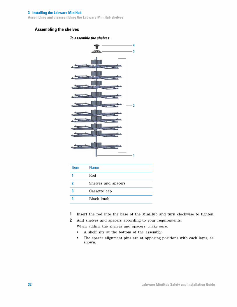
To assemble the shelves:
1 Insert the rod into the base of the MiniHub and turn clockwise to tighten.
2 Add shelves and spacers according to your requirements.
When adding the shelves and spacers, make sure:
• A shelf sits at the bottom of the assembly.
• The spacer alignment pins are at opposing positions with each layer, as shown.
4
3
2
1
Item Name
1 Rod
2 Shelves and spacers
3 Cassette cap
4 Black knob
32 Labware MiniHub Safety and Installation Guide

3 Installing the Labware MiniHubAssembling and disassembling the Labware MiniHub shelves
• The shelves are correctly aligned and seated securely. Use the spacer alignment pins to ensure correct alignment.
• If you are using a subset of the shelves, you can add the 8.4- mm spacers at the top of the assembly to fill the space between the top-most 25.1- mm spacer and the cassette. (You do not need to add the 8.4- mm spacers if all of the shelves are used.)
You can add two or more 25.1- mm spacers between shelves to accommodate tall labware. (In this case, some shelves will not be used.) The highest shelf you can install depends on the maximum access height of the automation system robot and the MiniHub model.
3 Place the cassette cap at the top of the rod.
4 Add the black knob at the top of the rod and turn clockwise to tighten it.
To reconfigure the shelves:
1 Turn the black knob at the top of the Labware MiniHub counterclockwise and remove it.
2 Lift and remove the cassette cap.
3 Lift and remove the spacers and shelves from the rod.
4 If you are replacing the threaded rod:
a Turn the rod counterclockwise to remove it from the base.
b Insert the new rod at the center of the base and turn it clockwise to tighten it.
5 Add spacers and shelves according to your requirements.
6 Place the cassette cap at the top of the rod.
7 Place the black knob at the top of the rod and turn clockwise to tighten it.
To disassemble the shelves:
1 Turn the black knob at the top of the Labware MiniHub counterclockwise and remove it.
2 Lift and remove the cassette cap.
3 Lift and remove the spacers and shelves from the rod.
4 Turn the rod counter- clockwise in the base and remove it.
33Labware MiniHub Safety and Installation Guide
3 Installing the Labware MiniHubAssembling and disassembling the Labware MiniHub shelves
5 Pack the shelves, spacers, rod, cassette cap, and black knob in their original shipping containers. See the Labware MiniHub Unpacking Guide for instructions.
Related information
For information about... See...
Turning on the Labware MiniHub Labware MiniHub User Guide
Starting up the automation system Automation system user documentation
Setting up the Labware MiniHub in the VWorks software
Labware MiniHub User Guide
Using the MiniHub ActiveX control Labware MiniHub User Guide
34 Labware MiniHub Safety and Installation Guide


Safety and Installation Guide
G5471-90004
Revision B, June 2015