today: battery pack modeling and bmsecee.colorado.edu/~ecen5017/lectures/cu/l15_slides.pdf ·...
TRANSCRIPT

Today: Battery pack modeling and BMS
• Battery pack: Stack battery cells in parallel and series• BMS: Monitor battery state (voltage, SOC, SOH), perform cell balancing, communicate with vehicle controller
1
DC busDC-DC
converter
BatteryManagementSystem (BMS)
Control bus
Vbat
+
_
VDC
+
_
Electric drivepropulsioncomponents
Vehiclecontroller
ncells
(+protection)in
series
Conventional Battery System
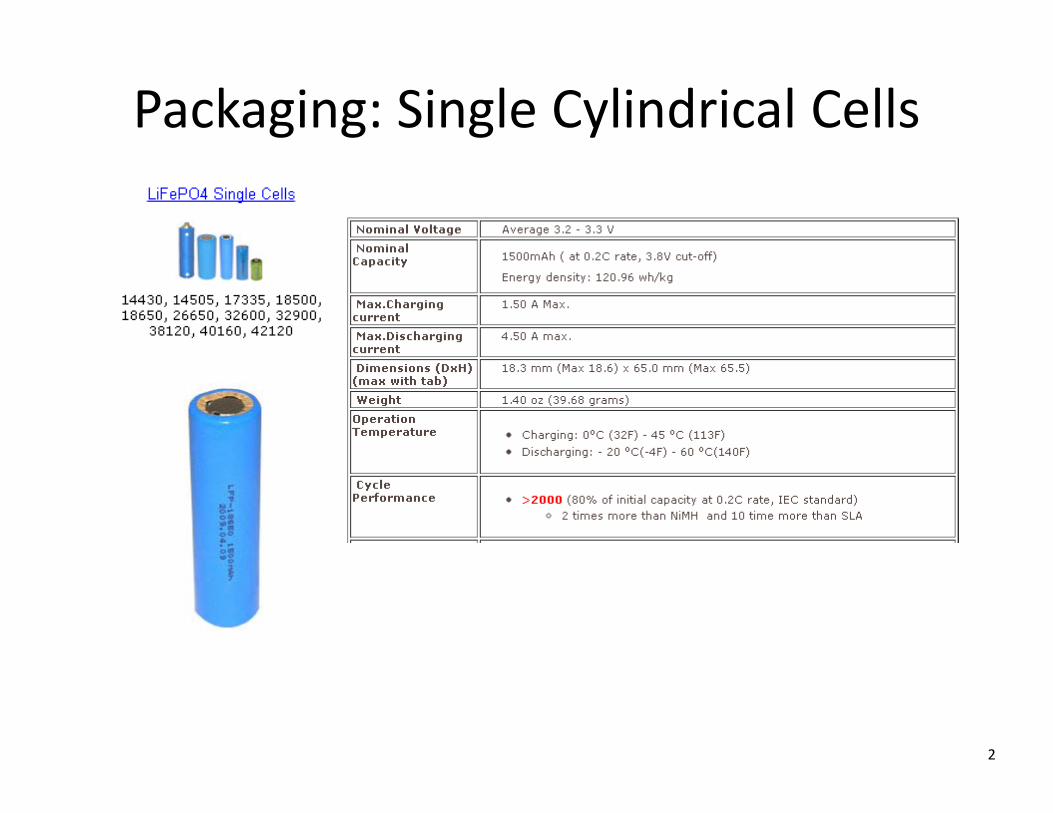
Packaging: Single Cylindrical Cells
2
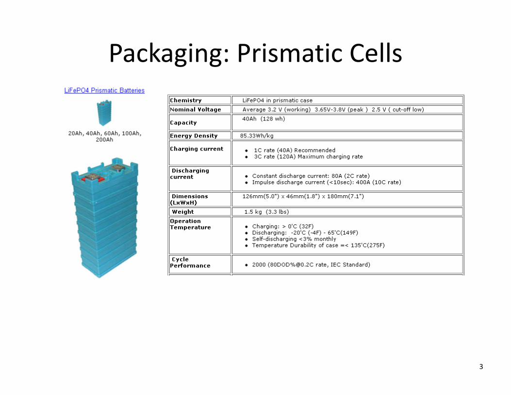
Packaging: Prismatic Cells
3

Battery Packs
4
Nissan LeafFord C‐Max Energi

Temperature Effects: Cell Characteristics
5
Cnom = 20 Ah cell tested at 0.5C charge/discharge rate
Reference: S. Chackoa, Y. M. Chunga, Thermal modeling of Li‐ion polymer battery for electric vehicle drive cycles, Journal of Power Sources, Volume 213, 1 September 2012, Pages 296–303
Temperature effects: aging and cycle life
6
• Crystal formation around the electrodes, reduces the effective surface area
• Passivation: growth of a resistive layer that impedes the chemical reactions
• Corrosion consumes some of the active chemicals
Aging leads to:• Increased series resistance, reduced power rating• Reduced capacity
End of life: drop to 80% of the original power or capacity rating
All of aging processes are accelerated with increased temperature
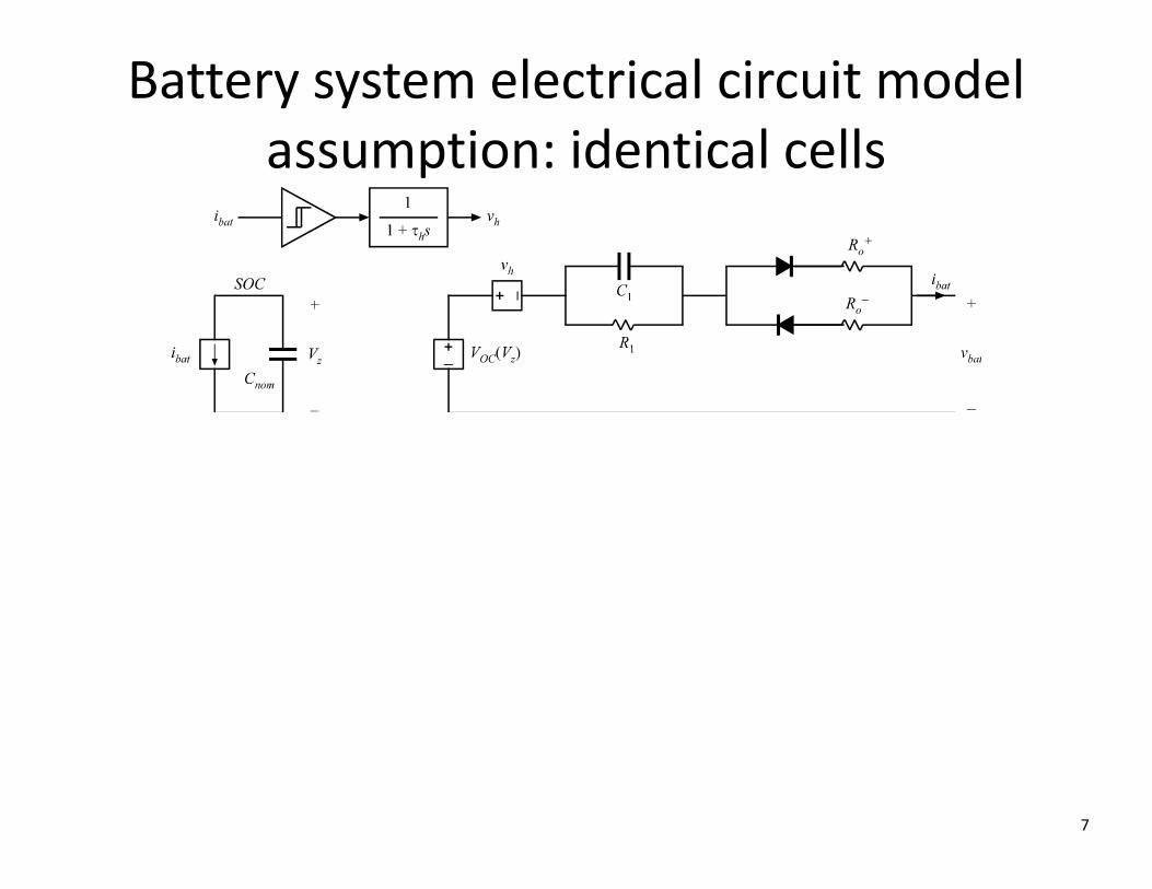
Battery system electrical circuit modelassumption: identical cells
7

Battery Simulink Model
8
ECEN5017Battery Model (D)
Mp = number of cells in parallelNs = number of cells in series
SOC
Open-circuit voltageas a function of SOC
Series resistances
Diffusion
2SOC
1Vbat
positive Ibat
output voltage
loop
negative Ibat
1-D T(u)
Voltage-vs-SOCCharacteristic
>= 0
Switch
Rp/Mp
Series resistance for Ibat>0
Rn/Mp
Series resistance for Ibat<0
R1
R1 (diffusion)
100
PercentConversion
Ns
Number ofcells in series
1s
IntegratorLimited
Ibat Vh
Hysteresis
1
tau1.s+1Diffusionlow-pass
etaC
Coulombefficiency
-1/(Mp*Cnom*3600)
Cnom(capacity in Ah)
1Ibat
SOCVz VOC_cell
Vsp
Vsn
Vr
Vcell
Vh
Ibat
Vbat
R1/Mp
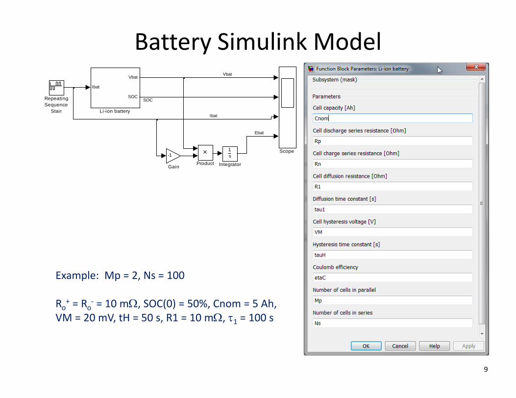
Battery Simulink Model
9
Scope
RepeatingSequence
Stair
Product
Ibat
Vbat
SOC
Li-ion battery
1s
Integrator
-1
Gain
Ibat
Vbat
SOC
Ebat
Example: Mp = 2, Ns = 100
Ro+ = Ro‐ = 10 m, SOC(0) = 50%, Cnom = 5 Ah, VM = 20 mV, tH = 50 s, R1 = 10 m, 1 = 100 s

Battery waveforms (an example)
10
300
350
400
0 10 20 30 40 50 600
50
100
-10
0
10
0
2
4x 10⁶
92.3%

Charging
11

CCCV Charging example
12
360
370
380
390
0 10 20 30 40 50 600
50
100
-10
0
10

Effects of cell mismatches and the need for battery management system (BMS)
13
Reference: Davide Andrea, Battery Management Systems for Large Lithium‐IonBattery Packs, Artech House 2011, http://book.liionbms.com/
Mismatches in cell characteristics• Capacity• Leakage (self‐discharge) current• Other parameters: series resistance, …Mismatches in cell SOC’s during operation
Animations at: http://liionbms.com/balance/index.html

Cell versus system capacity [Ah]
14
Discharge, assuming equal starting SOC=100%
ii SOCCQ min,1
iCC minmin
01min CQ
minCCsystem
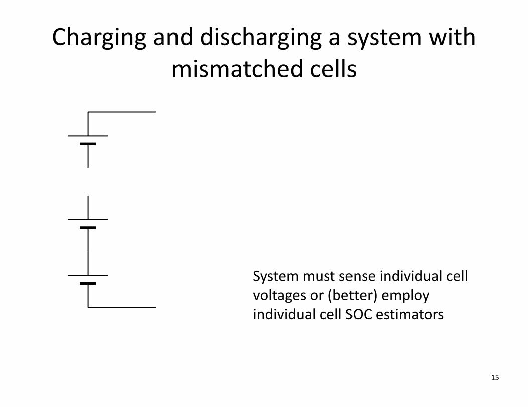
Charging and discharging a system with mismatched cells
15
System must sense individual cell voltages or (better) employ individual cell SOC estimators
16
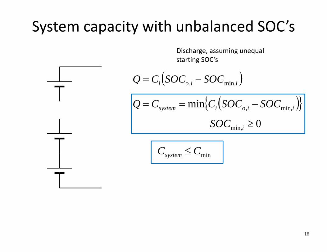
Discharge, assuming unequal starting SOC’s
iioi SOCSOCCQ min,,
minCCsystem
System capacity with unbalanced SOC’s
iioisystem SOCSOCCCQ min,,min
0min, iSOC

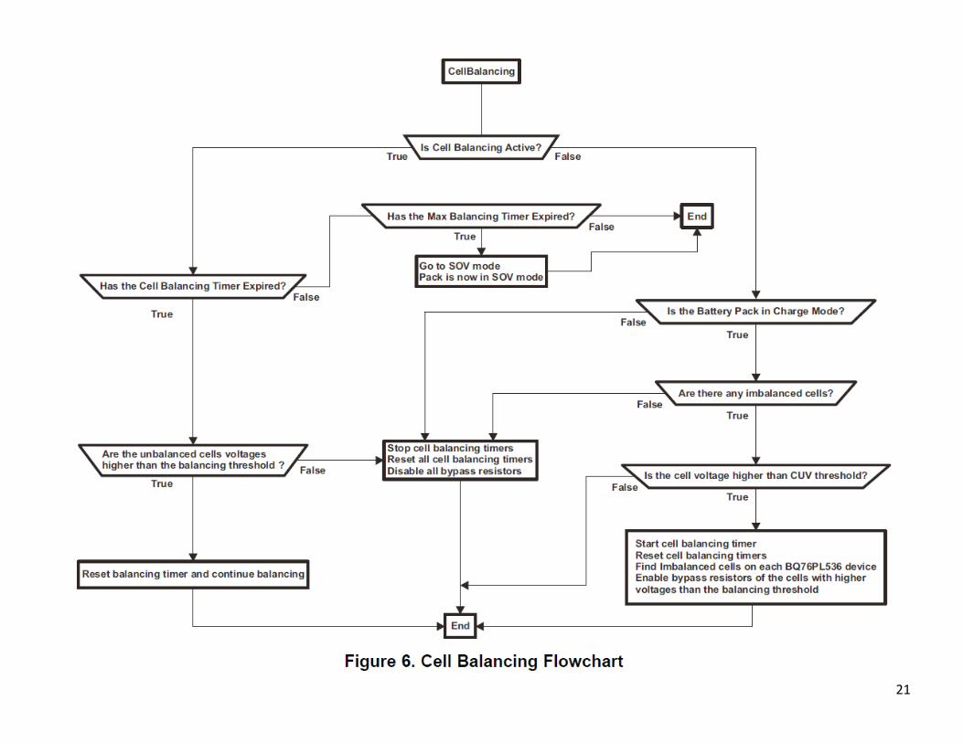
Passive “top” balancing
17Animated example: http://liionbms.com/balance/index.html

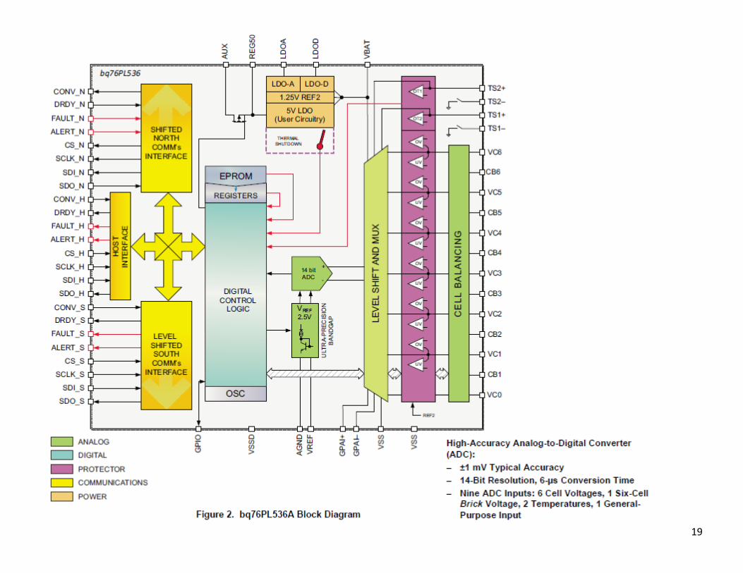
Example: TI bq76PL536A
18
19
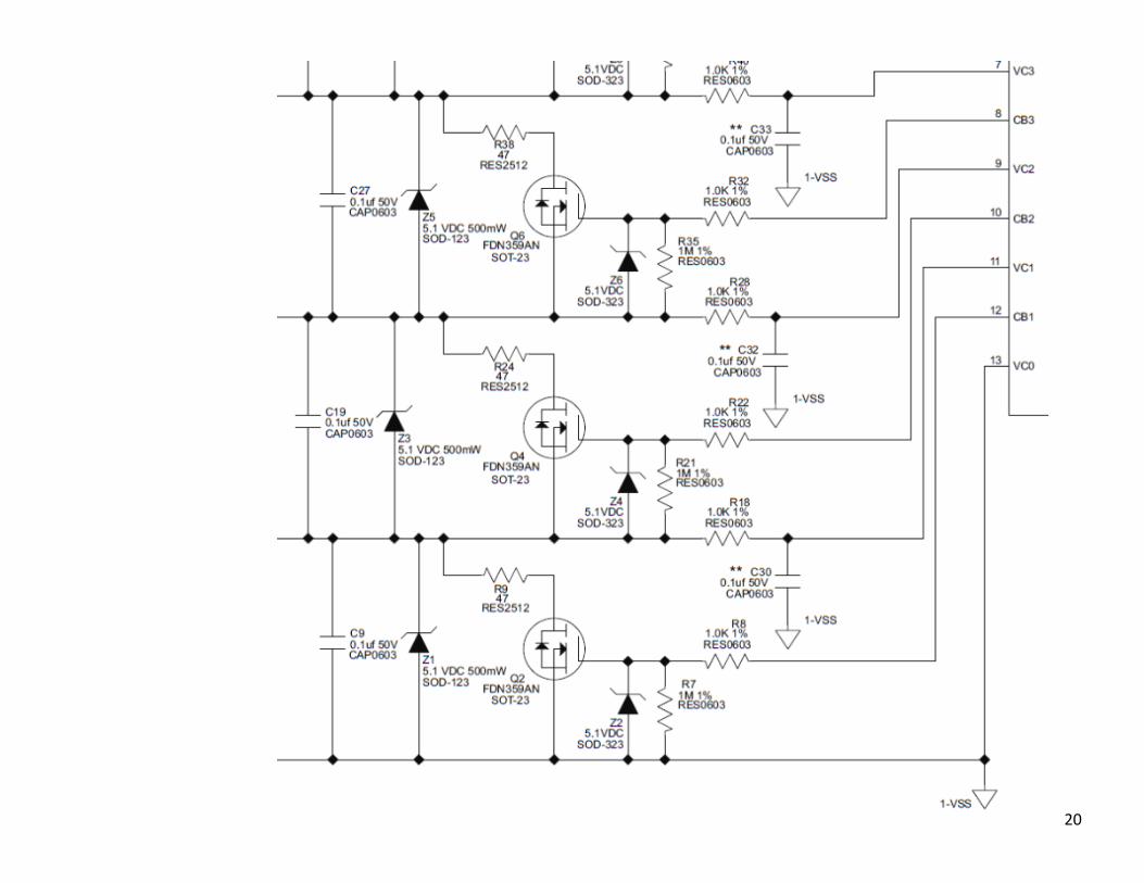
20
21

Active balancing
22
Example: switched‐capacitor charge shuttling

Active balancing architectures
23
http://liionbms.com/php/wp_passive_active_balancing.php

Cell versus system capacity [Ah] with charge re‐distribution
24
Discharge, assuming equal starting SOC=100%
isystem CC