to order visit - ameradio.com · one serial communication ... this section guides you in the...
TRANSCRIPT

MICOM-2/2EHF-SSB Transceiver
Computer Interface Software
Motorola Inc., 1998
Motorola, Inc.Land Mobile Products Sector1301 E. Algonquin RoadSchaumburg, IL 60196
User’s Guide
68P02950C35-BApril, 1998
American Communication SystemsDiscover the Power of Communications ™
TO ORDER – VISIT http://www.ameradio.com


MICOM-2/2EHF-SSB Transceiver
Computer Interface Software
Motorola Communications Israel Ltd. 1998A subsidiary of Motorola Inc.All rights reserved.
Land Mobile Products Sector16 Kremenetski Street, Tel Aviv 67899
Printed in Israel, April, 1998User’s Guide
68P02950C35-B


iii
Table of Contents
Acronyms and Abbreviations............................................................. vii
Introduction ..............................................................................................1
Application.................................................................................................1Prerequisites .............................................................................................1Computer Interface Contents....................................................................1Computer Configuration Requirements ....................................................2Computer Support.....................................................................................2
Getting Started.........................................................................................3
General .....................................................................................................3How to Install the Software .......................................................................3How to Connect the Radio to your Computer ...........................................3How to Start the Computer Interface Application ......................................3
The Main Window ....................................................................................5
The Title Bar..............................................................................................5Menu Bar...................................................................................................6Tool Bar.....................................................................................................7Application Status Line..............................................................................8
General Operation...................................................................................9
General .....................................................................................................9Loading the Control Panel.........................................................................9Loading Parameters from the Radio.......................................................10Loading Parameters from a File .............................................................10Selecting the Language ..........................................................................10Changing the Title of the Radio Window................................................. 11Customizing the Computer Interface Communication Parameters ........ 11Radio Communication Parameters.........................................................13Resetting the Radio.................................................................................13

MICOM-2/2E CI Software User’s Guide
iv
MICOM-2 (Basic) Control Panel Window ........................................15
Radio Display ..........................................................................................16LCD Display.........................................................................................16Status Annunciators .............................................................................16Radio LEDs..........................................................................................16Minimize Button ...................................................................................16
Clarifier....................................................................................................17The Card Board ......................................................................................17Channel/Scan Tab...................................................................................17
Channel Mode Controls .......................................................................17Status Line ...........................................................................................19Scan Mode Controls ............................................................................19Command Status Line .........................................................................20Buttons.................................................................................................21
Link Tab...................................................................................................21Link Mode Controls..............................................................................22Buttons.................................................................................................23Command Status Line .........................................................................23
MICOM-2 (Basic) Operation................................................................25
General ...................................................................................................25Turning Squelch On or Off ......................................................................25Setting the Clarifier..................................................................................26Selecting and Configuring a Channel......................................................27Setting the Priority Channel ....................................................................28Selecting a Group and Scanning ............................................................28
Entering Scan Mode ............................................................................28Exiting Scan Mode...............................................................................28
Activating/Deactivating the SelCall Option..............................................29Monitoring the Speaker ...........................................................................29Entering SelCall Mode ............................................................................30
Making Selective Calling......................................................................30Aborting Selective Calling....................................................................30
Replying to Calls in SelCall Mode ...........................................................31

Contents
v
Using the Stack .......................................................................................31Viewing the Stack List..........................................................................32The Stack List Toolbar .........................................................................33Replying to Unanswered Calls.............................................................34
Using the Log File ...................................................................................34Viewing the Log File ............................................................................34The Log List Toolbar ............................................................................36
MICOM-2E (Enhanced) Control Panel Window .............................37
Radio Display ..........................................................................................38Mode Display .......................................................................................38Information Display..............................................................................38Icon Display .........................................................................................38Transmission Bar (Tx) .........................................................................38Receive/Transmit Level .......................................................................39Minimize Button ...................................................................................39
Clarifier....................................................................................................39Notch Filter..............................................................................................39The Card Board ......................................................................................39Channel/Scan Tab...................................................................................40
Channel Mode Controls .......................................................................40Status Line ...........................................................................................42Scan Mode Controls ............................................................................42Command Status Line .........................................................................43Buttons.................................................................................................44
Link Tab...................................................................................................44Buttons.................................................................................................46Command Status Line .........................................................................46
Update Link Quality Tab..........................................................................47Buttons.................................................................................................48Command Status Line .........................................................................48

MICOM-2/2E CI Software User’s Guide
vi
MICOM-2E (Enhanced) Operation.....................................................49
General ...................................................................................................49Turning Squelch On or Off ......................................................................50Turning the Noise Blanker On or Off.......................................................50Turning the Attenuator On or Off.............................................................50Turning the Clipper On or Off..................................................................50Setting the Clarifier..................................................................................50Setting the Notch Filter............................................................................51Selecting and Configuring a Channel......................................................52Setting the Priority Channel ....................................................................54Selecting a Group and Scanning ............................................................54
Entering Scan Mode ............................................................................54Exiting Scan Mode...............................................................................54
Activating/Deactivating the ALE Option...................................................55Monitoring the Speaker ...........................................................................55Entering ALE Mode .................................................................................56
Making Selective Calling......................................................................56Re-establishing a link on a different channel.......................................56Disconnecting/Aborting Selective Calling ............................................57
Replying to Calls in ALE Mode................................................................57Setting Sounding ON and OFF ...............................................................58Bidirectional Transmission ......................................................................59Using the Stack .......................................................................................60
Viewing the Stack List..........................................................................61The Stack List Toolbar .........................................................................62Replying to Unanswered Calls.............................................................63
Using the Log File ...................................................................................63Viewing the Log File ............................................................................63The Log List Toolbar ............................................................................65
Keyboard Shortcuts .................................................................................66

vii
Acronyms and Abbreviations
AGC Automatic Gain Control
ALE Automatic Link Establishment
AME Amplitude Modulation Equivalent
ARQ Automatic Repeat Request
BDIR Bidirectional
CI Computer Interface
HF High Frequency
LCD Liquid Crystal Display
LED Light Emitting Diode
LSB Lower Side Band
Net Network
PLT Pilot (mode)
RSS Radio Service Software
Rx Receive
SelCall Selective Calling
SQ Squelch
Tx Transmit
ULQ Update Link Quality
USB Upper Side Band


1
Introduction
ApplicationThe MICOM-2/2E is a high performance, DSP-based, multi-purposeHF-SSB radio. It is intended for use in voice, data, and fax operation,in mobile or base station configurations. The MICOM-2/2E is operatedfrom its integral front panel or remotely via a personal computer. It canbe integrated into a large variety of advanced systems such as data andfax networks, VHF-UHF-microwave and telephone interconnect, highpower (400W/1000W) systems, and so on.
The Computer Interface (CI) user’s guide is designed for users who wish to control the MICOM-2/2E radio from a remote or local location,using a personal computer (IBM PC or compatible).
Important: For more information on the MICOM-2/2E options and onhow various functions described in this User’s Guide, such as scanning, groups, selective calling, nets, and so on, see any of the followingmanuals relevant to your specific equipment:
MICOM-2 HF SSB Transceiver, Owner’s Manual (68P02941C60)
MICOM-2 HF SSB Transceiver Digital Selective Calling Option(68P02950C95)
MICOM-2E HF SSB Transceiver, Owner’s Manual (68P02952C60)
It is highly recommended that you read these manuals and familiarizeyourself with the functions of the MICOM-2/2E prior to using theCI application.
PrerequisitesTo use the CI software to control the radio, a basic working knowledgeof Microsoft Windows is recommended. If you are new to the Windowsoperating environment, you should learn Windows fundamentals–using the mouse, working with windows, and opening and closingdocuments–before you begin to work with the CI software.
Computer Interface ContentsThe CI option (Motorola part no. S947) consists of the following:
1. Application software, available on 3½ inch diskettes
2. This User’s Guide (68P02950C35)3. An RS232 cable (FKN4617A).

MICOM-2/2E CI Software User’s Guide
2
The CI option can also be ordered as a field retrofit kit. In this case, theradio model must be stated when ordering the kit, as follows:
For Micom-2 (Basic): Motorola part no. FLN2423
For Micom-2E (Enhanced): Motorola part no. FLN2423
Computer Configuration RequirementsIn order to communicate with the radio using the CI, an IBM-PC with thefollowing configuration is required:
486DX/66 MHz or higher 16 MB RAM A monitor with a minimum resolution of 800x600 and at least 256
colors Microsoft Windows operating system version 3.11 Free hard disk space of at least 12 Mbytes One 3½ inch, 1.44 MB floppy disk drive One serial communication port A mouse
Computer SupportIf you encounter a problem, first check your hardware setup.Problems requiring additional analysis should be referred to:
Motorola Radio Support Center3761 S. Central AvenueRockford, IL 61102, USATel: (847) 725 4830 or (800) 227 6772
Global Data Specialists3707 E. Broadway Road,Suite 2,Phoenix, AZ 85040, USATel: (602) 437 4331Fax: (602) 437 1858
US Federal customers should contact:
Motorola USFG Depot7940 Penn Randall PlaceUpper Marlboro, MD 20772Tel: (301) 736 4300 or (800) 969 6680Fax: (301) 735 7414 or (800) 784 4133

3
Getting Started
GeneralThis section guides you in the installation of the MICOM-2/2E ComputerInterface Software and in the connection of the radio to your computer.
How to Install the SoftwareThe Computer Interface Software is shipped to you on 3½ inchdiskettes. To set the software up on a hard disk, proceed as follows:
1. Insert the CI Install disk (disk 1) into drive A.
2. Enter Windows.If Windows is already running, close any open applications.
3. From the File menu, choose Run
4. Type a:setup (or b:setup) and then press [Enter].
5. Follow instructions on the screen.
If the installation process is completed successfully, the CI software isnow installed on your hard disk and a new program group has beencreated in your Program Manager window named MICOM-2/2EComputer Interface.
How to Connect the Radio to your ComputerConnect the “radio” side of the RS232 cable to the Accessory connector on the radio rear panel. Connect the “computer” side of the RS232 cable to the PC serial port. If necessary, use a D25-to-D9 adapter.
How to Start the Computer Interface Application1. Turn on your computer; at the DOS prompt, type “win” and press
[Enter].
2. Connect your radio to the computer.
3. Turn the radio on.
4. Double-click the Computer Interface icon. The application starts torun, and after a few seconds the main window of the CI appears onthe screen.

4
The Main Window
After the application has completed initialization, the CI main windowappears. The main window is comprised of a title bar, a menu bar, a toolbar and an application status line.
Window TitleTitle Bar Tool BarMenu Bar
Application Status Line
Figure 1. CI Main Window
The Title BarThe title bar of the main window indicates the radio name or any othername given by the user.

The Main Window
5
Menu BarThe menu bar enables the selection of commands and dialog boxes,using the mouse or keyboard shortcuts. Figure 2 displays a tree of themenus.
Figure 2. CI Menu Tree

MICOM-2/2E CI Software User’s Guide
6
Tool BarThe tool bar enables the user access to commonly used commands anddialog boxes, by clicking an icon (button).
The icons available in both MICOM2 and MICOM2E are:
Open Opens an existing radioparameter file (default file)
Read Device Loads parameters from theradio
Communication Ports Selects the baud rate and thecomputer communication port(dialog box)
Squelch ON/OFF Turns the squelch circuit onor off. When squelch is on,the speaker remains muteduntil the radio detects a validsignal in its input. Whensquelch is off, the speakeremits all signals, includingnoise.
Monitor Mute ON/OFF Mutes or unmutes thespeaker in SelCall/ALE mode.

The Main Window
7
Special icons available only in MICOM2E are:
Noise Blanker ON/OFF Activates/deactivatesrepetitive noise filter.
Clipper ON/OFF When on, uses voiceprocessing to boost theoutput power.
Attenuator ON/OFF When on, attenuates theincoming signal by 20dB.
Help Displays on-line help.
Exit Exits the CI application
Application Status LineThis line contains five fields that describe the application status:
Status: Displays the position of the mouse cursor.
File/Radio: Displays “File” if the application loads the radio data base from a file; otherwise, “Radio” is displayed.
S/N: Displays the radio’s serial number.
Code: Displays the radio’s code (this code can not be changed).
COM: Displays the communication port and baud rate.

8
General Operation
GeneralThis section describes how to:
Load the control panel
Load parameters from the radio
Load radio parameters from a file
In addition, general CI operations are described, including:
Renaming the application
Selecting a language
Customizing the CI serial communication parameters
Resetting the MICOM-2/2E Radio
Loading the Control PanelWhen you run the CI application, the main window opens while theprogram examines whether the CI data base is empty or containsentries. If the data base is empty, a black screen opens. If there areentries in the database, the CI automatically loads the CI control panel.
Note: The CI application is shipped from the factory with an emptydatabase file. When you first open the application, the Opencommand in the File menu and the Open button are disabled.Once you have read the radio parameters from the radiousing the Read Device command, they are automaticallysaved in the database file, which will then be availablethrough the Open command.

General Operation
9
Loading Parameters from the RadioThe Read Device command uses a serial communication interface toload the radio parameters directly from the radio. This method of loadingthe radio parameters is time consuming and is not recommended on aregular basis.
Step 1. From the File menu, choose Read Device, or click the ReadDevice button on the toolbar.
A window with a progress bar appears. The bar advances fromleft to right, indicating the progress of loading parameters fromthe radio into the computer.
The loaded parameters are automatically saved in a default file.
Note: If there is no response from the radio, or if the communicationparameters (baud rate or communication ports) are notcompatible, a communication failure message appears.
Loading Parameters from a FileThe Open command in the File menu enables you to load radioparameters directly from the database file. This is the fastest andrecommended manner of loading the radio parameters.
Step 1. From the File menu, choose Open.
Alternatively, click the Open button on the toolbar.
Note: If the radio configuration has been changed using the RSS,click the Read button to read the new radio parameters intothe CI database.
Selecting the LanguageThe CI software can display texts and messages in three differentlanguages: English, French and Spanish.
Step 1. From the Preferences menu, choose Language.
Select the required language from the drop-down list.

MICOM-2/2E CI Software User’s Guide
10
Changing the Title of the Radio WindowThis option enables you to change the title of the radio which appears inthe window’s title bar.
To change the title of the radio window:Step 1. From the Preferences menu, select Application Name.
An input message box appears.
Step 2. Type a new name and press [Enter] or click the OK button.
The application name is replaced with the new name.
Customizing the CI Communication ParametersYou can customize the CI serial communication parameters,i.e., communication ports and baud rate.
The communication port and baud rate are displayed on the applicationstatus line.
To customize CI communication parameters:Step 1. From the Preferences menu, choose Comm. Ports.
The Communication Ports dialog box is displayed.
Figure 3. The Communication Ports Dialog Box
General Operation
11
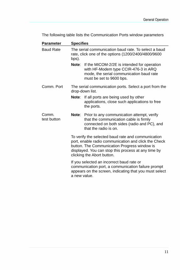
The following table lists the Communication Ports window parameters
Parameter Specifies
Baud Rate The serial communication baud rate. To select a baudrate, click one of the options (1200/2400/4800/9600bps).Note: If the MICOM-2/2E is intended for operation
with HF-Modem type CCIR-476-3 in ARQmode, the serial communication baud ratemust be set to 9600 bps.
Comm. Port The serial communication ports. Select a port from thedrop-down list.Note: If all ports are being used by other
applications, close such applications to freethe ports.
Comm.test button
Note: Prior to any communication attempt, verifythat the communication cable is firmlyconnected on both sides (radio and PC), andthat the radio is on.
To verify the selected baud rate and communicationport, enable radio communication and click the Checkbutton. The Communication Progress window isdisplayed. You can stop this process at any time byclicking the Abort button.
If you selected an incorrect baud rate orcommunication port, a communication failure promptappears on the screen, indicating that you must selecta new value.

MICOM-2/2E CI Software User’s Guide
12
Radio Communication ParametersThe MICOM-2/2E radio has the following communication parameters:
Baud rate: 1200,2400,4800 or 9600 (user selectable)
Data bits: 8 (factory setting)
Stop bits: 1 (factory setting)
Parity: Odd (factory setting)
Resetting the RadioThis option enables you to reset the MICOM-2/2E radio.
Step 1. From the Preferences menu, select User>Reset.
The radio receives the reset command and initializes itself tothe last stable state. The radio then sends a message to theapplication to synchronize the displayed parameters.

General Operation
13

14
MICOM-2 (Basic) Control Panel Window
Once the radio parameters are loaded into the CI, the control panelwindow appears. The control panel includes the radio display, a clarifier,and a card board (comprised of a channel tab and a link tab).
Radio Display ClarifierCard Board
Tab Label(Channel or Scan)
Tab Label(Link)
Figure 4. Control Panel

MICOM-2 (Basic) Control Panel Window
15
Radio DisplayThis box simulates the LCD display of the radio, including an LCD textand icon display, LEDs, and a Minimize button.
LCD DisplayThe LCD display consists of eight characters, indicating the radio statusand providing information such as channel or scan mode, transmission,clarifier, frequency, and radio errors.
Status AnnunciatorsAbove the character display are five status icons which indicate fiveparameters of the radio operating status: clarifier, noise blanker (NB),monitor, stack, and alarm.
Clarifier icon
Noise blanker icon
Monitor icon
Stack icon
Alarm icon
Radio LEDsThe three LEDs indicate the radio PTT condition, radio mode andsquelch condition, as follows:
LED Color Lights when...
Tx Red the PTT key is pressed.
LSB Orange the radio is in LSB mode.
SQ Green the squelch circuit is active.
Minimize ButtonThe minimize button enables you to reduce the CI main window so thatonly the radio display is visible.
ClarifierThe clarifier enables fine tuning of the receive frequency to improvevoice quality when the incoming signal is slightly off frequency. The

MICOM-2/2E CI Software User’s Guide
16
clarifier can be turned off and is automatically disabled duringtransmission.
The upper and the lower frequency deviation limits are ±200Hz.
Note: When the radio switches to a new channel, the clarifier isautomatically turned off.
The Card BoardThe card board contains all information and variable parametersnecessary to control the radio in various modes and activities such aschannel mode, scan mode, selective call, replying calls and so on.
The card board consists of two tabs, Channel/Scan and Link. TheChannel/Scan tab is used for channel and scan modes, and the Link tabis used for selective calling, link information, display of unansweredcalls, and reply to unanswered calls.
Note: In MICOM-2 radios equipped with the SelCall option, only theChannel/Scan tab is visible when SelCall mode is off.
Channel/Scan TabThe Channel/Scan tab includes channel and scan controls. Only one ofthese controls appears on the screen, depending on whether the radiois in channel or scan mode.
Channel Mode Controls
Figure 5. Channel/Scan Tab, in Channel Mode
The following table lists the channel controls and parameters:
Parameter IndicatesChannel drop down The number of the selected channel.

MICOM-2 (Basic) Control Panel Window
17
Tx Frequency read-only The transmit frequency (MHz).Frequency range: 1.6 MHz–30 MHz.
Rx Frequency read-only The receive frequency (MHz).Frequency range: 0.1 MHz–30 MHz.
Band drop down Side band operation:Upper Side Band or Lower Side Band.
AGC read-only Automatic (receive) Gain Control:Slow–used for voice communicationFast–generally used for data transmission
(only when required by the HF datamodem).
Tx Power read-only Transmit power level:low 25 Watt high 100 Wattmedium 60 Watt max. 125 Watt
Note: When a 400W/1000W amplifier is connected tothe radio, the transmitted power is 400W/1000Wand not as displayed in the Tx Power box.
Mode read-only Carrier reinsertion level:SSB (Single Side Band)–The radio
operates on the upper side band withsuppressed carrier.
AME (Amplitude Modulation Equivalent)–The radio operates on the upper/lower sideband with the carrier inserted 6 dB belowpeak envelope power.
PLT (Pilot mode)–The radio operates onthe upper/lower side band with the carrierinserted 15 dB below peak envelope power.
Bandwidth read-only The bandwidth of the current channel.Note: MICOM-2 has only one bandwidth–2700 Hz.

MICOM-2/2E CI Software User’s Guide
18
Status LineIn the following cases, an error appears in the status line:
The typed channel/frequency is out of range.
The typed channel/frequency is not a numerical value.
The channel/frequency box is empty.
Note: If there is an error in the typed channel or frequency, youcannot press the set button.
Scan Mode ControlsIf the MICOM-2 radio is equipped with a SelCall option, two scan modesare available:
SelCall scan mode
Basic scan mode (enabled when SelCall is off)
Figure 6. Channel/Scan tab, in Scan Mode
The following table lists the channel controls and parameters:
Parameter Indicates
Group/Net drop down The selected Group/Net number
Net Name read-only The current Net Name(only in SelCall mode)
SelCall Scan mode
Note: This section refers only to MICOM-2 radios equipped with theSelCall option.

MICOM-2 (Basic) Control Panel Window
19
When the SelCall mode is operating, the MICOM-2 can automaticallyscan up to five nets (1, 2, 3, 4 and 5), each with up to 100 channels.
The nets are pre-programmed in the radio (using the RSS for SelCall),and each net has an assigned name (network address). In the CI, youcan switch from one net to another using the Scan Group drop-downmenu.
Basic Scan modeWhen the SelCall mode is off, or if your radio is not equipped with theSelCall option, the MICOM-2 operates in basic mode and canautomatically scan up to five groups (A, B, C, D and E), each with up to100 channels.
The groups are pre-programmed in the radio (using the radio’s RSS, depending on the radio model). In the CI, you can switch from onegroup to another by selecting a new group in the Scan Group drop-down menu.
An additional channel can be programmed as a “guard” channel. This channel is scanned more frequently than the other channels.
Command Status LineThe Status line registers error messages and other messages for theuser.
For example, if the last request is still in process, the message“Command in progress” appears in the Status line. If you attempt to issue a command while the radio is transmitting, the message “Radio istransmitting now, commands cannot be executed during transmitting” appears in the Status line.

MICOM-2/2E CI Software User’s Guide
20
ButtonsThe Channel/Scan tab command buttons are:
Set ButtonClick this button to download the selected channelnumber and its parameters to the radio.
Priority ButtonInstantaneously changes the current channel to apre-defined priority channel, overriding the currentstatus and the standard operating procedure.
Start/Stop Scan ButtonThe Start Scan button initiates scanning of channelsin the currently selected group. This is considered theRadio Scanning state.
The Stop Scan button stops radio scanning.The radio status switches to Channel mode.
Link TabNote: This paragraph refers only to MICOM-2 radios equipped with
the SelCall option.
In radios equipped with the SelCall option, this tab is visibleonly if the SelCall option is active.
The SelCall Link tab includes all SelCall controls and displays allSelCall status information.
In the SelCall tab, you can:
Select the net, channel, and station
Perform selective calling
Display unanswered calls
Reply unanswered calls.

MICOM-2 (Basic) Control Panel Window
21
Link Mode Controls
Figure 7. Link Tab
The following table lists the SelCall controls and parameters:
Parameter Indicates
Call Type typeselection
The required selective call type: Station–private call Net–all members in a specific net All Call–broadcast call
Net drop down Lists all available nets and displays thename of the selected net.
Channel drop down Lists all available channels in theselected net and displays the Rxfrequency of the selected channel.
To drop down Lists all station and net names stored inthe SelCall directory.

MICOM-2/2E CI Software User’s Guide
22
ButtonsThe SelCall tab command buttons are:
Send ButtonClick this button to initiate Selective Calling.
Stack ButtonDisplays all unanswered calls in SelCall mode.
Abort ButtonDisconnects/aborts selective calling.
Command Status LineThe Status line registers error messages and other messages for theuser.
For example, if the last request is still in process, the message“Command in progress” appears in the Statusline. If you attempt toissue a command while the radio is transmitting, the message “Radio is transmitting now, commands cannot be executed during transmitting” appears in the Status line.

MICOM-2 (Basic) Control Panel Window
23

24
MICOM-2 (Basic) Operation
GeneralThis section describes how to operate the MICOM-2 radio using the CI(Computer Interface) software. The operations available depend on thespecific radio model.
For all models, the CI enables the user to:
Turn the squelch on or off
Set the clarifier
Select or change a channel and change its configuration
Set the priority channel
Select or change a group and start or stop scanning
For MICOM-2 radios equipped with the SelCall option, the CIenables the user to:
Activate/Deactivate the SelCall option
Monitor the speaker
Initiate selective calling
Reply to calls in SelCall mode
Use the stack option
Reply to unanswered calls
View the SelCall log file
Turning Squelch On or OffTo turn squelch on or off, click the squelch button or choose Squelchfrom the Commands menu. The squelch is a toggle button, i.e. eachtime you click it, the squelch circuit changes its state from on to off andvice versa.
You can set the squelch state regardless of the current mode of the CIapplication.

MICOM-2 (Basic) Operation
25
Setting the ClarifierThe clarifier enables fine tuning of the receive frequency to improvevoice quality when the incoming signal is slightly off frequency. Theupper and the lower frequency deviation limits are ±200Hz.
To change the clarifier setting in predefined steps, use the left and rightbuttons to decrease/increase the clarifier deviation by 10 Hz.
To set the clarifier at a specific frequency deviation, drag and drop thecoarse button.
To set the clarifier to off, click on the “0” digit.
Coarse Button
Click "0" to turn clarifier off
Figure 8. The Clarifier Box

MICOM-2/2E CI Software User’s Guide
26
Selecting and Configuring a ChannelThe MICOM-2 radio can have up to 100 programmed channels.
Note: The radio can only be set to channels that have beenprogrammed using the Radio Service Software (RSS).
To select a new channel using the Channel box:Step 1. Open the Channel/Scan tab.
Note: If the radio is in Scan mode, press the Scan button to returnto Channel mode. The active tab will be “Channel”.
Step 2. Click the Channel drop-down list and select the requiredchannel from the list. If a scroll bar appears inside the list box,this means that there are more channels than displayed. Usethe scroll bar to scroll the list.
Alternatively, you can click inside the Channel box and type therequired channel number.
Selecting a new channel will automatically change all other fields in thedialog box to values stored in the computer’s memory for this channel.
Note: When new channel settings and configurations are selected,these are displayed on screen, but are not reflected in theradio.
To update the radio configuration, click the Set button or press [Enter].
To select a different band for the current channel:Step 1. Click the Band drop-down list and select the required band from
the list.
Alternatively, click inside the Band box and type “U” for USB (upper side band) or “L” for LSB (lower side band).
Note: When new band settings and configurations are selected,these are displayed on screen, but are not reflected in theradio.
To update the radio configuration, click the Set button orpress [Enter].
Setting the Priority ChannelTo set the radio to work with the priority channel, click the Priority buttonand wait for radio to respond. The radio changes its current channel to

MICOM-2 (Basic) Operation
27
the pre-defined priority channel, overriding the current status and thestandard operating procedure.
You can select a priority channel regardless of the current mode of theCI application.
Selecting a Group and ScanningTo select a scan group:Step 1. Click the Scan Group drop-down list and select the required
group (A, B, C, D, E, or SelCall Net 1,2,..5, if your radioincludes the SelCall option) from the list.
Note: When the radio is in scanning mode, each time you select anew group, the radio changes its scan group immediately.
Entering Scan ModeTo start scanning, click the Start Scan button. The tab name andconfiguration changes to the Scan tab. The radio enters Scan mode andbegins to scan channels in the currently selected group.
Exiting Scan ModeThere are three different ways to stop scanning:
Stop Scan Click the Stop Scan button.The radio stops scanning, the tab name andconfiguration changes to the Channel tab and theradio status reverts to Channel mode.
Priority Click the Priority button.The radio stops scanning, reverts to Channel mode,and sets the priority channel.
PTT Press the PTT (microphone) button.The radio immediately stops scanning at the lastchannel reached.
Note: The PTT option is available only when the radiois in basic scan mode.
Activating/Deactivating the SelCall OptionNote: This section refers only to MICOM-2 radios equipped with the
SelCall option.

MICOM-2/2E CI Software User’s Guide
28
You can activate or deactivate the Selcall option from the CI application.
To activate/deactivate the SelCall option:Step 1. From the Preferences menu select SelCall Option.
Wait until the application has completed any changes in thecontrol settings before proceeding.
Monitoring the SpeakerNote: This section refers only to MICOM-2 radios equipped with the
SelCall option.
When SelCall is active, you can switch the speaker on or off.
Step 1. From the Command menu, select Monitor.
Alternatively, click the Monitor button on the toolbar.
When Monitor is activated, the MON icon appear on the radioLCD display.
The Monitor button toggles from on to off and vice versa.
Note: The monitor function is only available when the SelCall modeis activated.

MICOM-2 (Basic) Operation
29
Entering SelCall ModeNote: This section refers only to MICOM-2 radios equipped with the
SelCall option.
Selective calling enables you to contact predefined nets.
If SelCall is not active, from the Preferences menu, select SelCall.
Making Selective CallingStep 1. Select the Link tab.
Step 2. Select the call type: Station, Net, or All Call.
Step 3. Open the Net drop-down list and select the identificationnumber of the net you wish to call from the net list box.
Alternatively, you can click inside the net box and type the net number.
Step 1. Open the Channel drop-down list and select a channel.
Step 2. If you selected call type Station, open the To drop-down list andselect a specific station name.
Step 3. Click the Send button to start calling.
Aborting Selective CallingStep 1. Click the Abort button on the Link tab.
The radio will send an Abort message to the remote station andwill revert to the last mode (Scan mode or Channel mode).
Note: If the HOME acknowledge flag is not on, the Abort messagewill not be sent to the remote radio (this parameter can beprogrammed in the RSS).

MICOM-2/2E CI Software User’s Guide
30
Replying to Calls in SelCall ModeNote: This section refers only to MICOM-2 radios equipped with the
SelCall option.
When the CI receives a SelCall request, a message box opens,notifying the user that an incoming selective call has been received.
Figure 9. The Incoming Private Call Dialog Box
You can confirm or reject the call:
To confirm the call, click the OK button in the message box. Thiswill cause the radio to confirm the call and establish the link.
To reject the call, click the Abort button in the message box. Thiswill cause the radio to send a reject message to the station thatperformed the call and to revert the radio to its previous state.
Using the StackNote: This section refers only to MICOM-2 radios equipped with the
SelCall option.
Unanswered calls in SelCall mode are stored in the Stack, which cansave up to 200 calls (depending on the log file size). When at least oneunanswered call is registered, the Stack button in the Link tab isactivated. If the stack is empty, i.e., there are no unanswered calls, theStack button is disabled.
Note: The contents of the Stack are not necessarily identical tothose of the radio cache. The Stack is only updated when theapplication is running and can store up to 200 unansweredcalls.

MICOM-2 (Basic) Operation
31
Viewing the Stack ListTo display the Stack log file, from the View/Change menu, select Stack.
Alternatively, click the Stack button in the Link tab.
A dialog box containing the list of station names and the date and timeof the unanswered calls appears. You can answer these calls directlyfrom the list, delete selected entries or all entries.
If the Stack list window is too small to contain the list of calls, a scrollbar appears on the right hand side of the window, enabling you to scrollthe list.
Figure 10. The Stack List
The following table details the information displayed in the Stack list:
Field Indication
From The caller’s station name
To The called station name
Date The date on which the call was made
Start The starting time of the call
End The ending time of the call
Call type The call type: Station, Net or All Call
Net number The net number
Channel The channel number
RowSelector

MICOM-2/2E CI Software User’s Guide
32
The Stack List ToolbarThe stack list toolbar enables quick access to commonly usedcommands and dialog boxes. To display or hide the toolbar, selectToolbar from the View/Change menu.
The stack list command buttons are:
DeleteClick this button to delete specific calls that you havemarked. To select multiple records, hold down the[Ctrl] button and click the rows in the row selector.
Delete AllClick this button to delete all unanswered calls.
ReplyClick this button to reply to an unanswered call thatyou have marked (one call only).
HelpClick this button to display on-line help.
CloseClick this button to close the Stack List window.

MICOM-2 (Basic) Operation
33
Replying to Unanswered CallsNote: This section refers only to MICOM-2 radios equipped with the
SelCall option.
To reply to an unanswered call registered in the Stack list:Step 1. Click the listing to which you wish to reply.
Step 2. Click the Reply button in the Stack list toolbar.
The CI application automatically performs the followingsequence:
The marked listing is deleted from the Stack list.
The Stack list is closed.
The Station name and all relevant information (net andchannel) are automatically loaded into the Link tab fields.
Step 3. Click the Send button to initiate the call.
Using the Log FileNote: This section refers only to MICOM-2 radios equipped with the
SelCall option.
Viewing the Log FileThe Log viewer enables you to view the log of all incoming and outgoingcalls.
To open the Log viewer window, from the View/Change menu, selectLog File.

MICOM-2/2E CI Software User’s Guide
34
Figure 11. The Log List
The log list contains the following information:
Field Indication
From The caller’s station name
To The called station name
Date The date on which the call was made
Start The starting time of the call
End The ending time of the call
Call type The call type: Station, Net or All Call
Net number The net number
Channel The channel number
If the Log list window is too small to contain the list of calls, a scroll barappears on the right hand side of the window, enabling you to scroll thelist.

MICOM-2 (Basic) Operation
35
The Log List ToolbarThe log list toolbar enables quick access to commonly used commandsand dialog boxes. To display or hide the toolbar, select Toolbar from theView/Change menu.
The log list command buttons are:
DeleteClick this button to delete specific calls that you havemarked. To select multiple records, hold down the[Ctrl] button and click the rows in the row selector.
Delete AllClick this button to delete all calls.
HelpClick this button to display on-line help.
CloseClick this button to close the Log List window.

36
MICOM-2E (Enhanced) Control Panel Window
Once the radio parameters are loaded into the CI, the control panel windowappears. The control panel includes the radio display, a clarifier, a Notch Filter,and a card board (comprised of a channel tab, link tab and Update LinkQuality).
Radio Display ClarifierCard Board
Tab Label(Channel or Scan)
Tab Label(Link)
Tab Label(Update Link Quality)
Figure 12. Control Panel

MICOM-2E (Enhanced) Control Panel Window
37
Radio DisplayThis box simulates the LCD display of the radio, and includes thefollowing elements: two textual displays (mode and information), an icondisplay, a transmission (Tx) bar, a receive/transmit level indicator, and aminimize button.
Mode DisplayIndicates the current working mode, for example CH# for channel mode,Freq. For frequency mode, ALE for ALE mode and so on.
Information DisplayInformation pertaining to the operation presently being performed in thecurrent working mode.
For example: when the radio is in Channel Mode, this line displays theactual frequency of the specified channel.
Icon DisplayAbove the textual display is the Icon Display, where any of the tenfollowing icons can be displayed, indicating various parameters of theradio’s operating status, as follows:
USB
LSB
Squelch
Monitor
Noise Blanker
Clarifier
Notch Filter
Bandwidth
AGC
Alarm
Transmission Bar (Tx)The transmission bar is displayed when the PTT button is pressed,indicating that the MICOM-2E is transmitting.

MICOM-2/2E CI Software User’s Guide
38
Receive/Transmit LevelIn Transmit mode, this bar displays the output power level.
In Receive mode, this bar displays the level of the received signal, whenthe receive level button is pressed.
Minimize ButtonThe minimize button enables you to reduce the main window of the CIso that only the radio display is visible.
ClarifierThe clarifier enables fine tuning of the receive frequency to improvevoice quality when the incoming signal is slightly off frequency. Theclarifier can be turned off and is automatically disabled duringtransmission.
The upper and the lower frequency deviation limits are ±200Hz.
Note: When the radio switches to a new channel, the clarifier isautomatically turned off.
Notch FilterThe notch filter reduces noise in a specific user-defined range within thechannel bandwidth, in order to improve voice quality. The notch filtercan be turned off and is automatically disabled during transmission.
Note: When the radio switches to a new channel, the notch filter isautomatically turned off.
The Card BoardThe card board contains all information and variable parametersnecessary to control the radio in various modes and activities such aschannel mode, scan mode, selective call, replying calls and so on.
The card board consists of three tabs, Channel/Scan, Link and UpdateLink Quality. The Channel/Scan tab is used for channel and scanmodes. The Link tab is used for selective calling, link information,display of unanswered calls, and reply to unanswered calls. The UpdateLink Quality tab is used for sounding and channel score management inALE mode.
Note: In MICOM-2E radios equipped with the ALE option, only theChannel/Scan tab is visible when the ALE mode is turned off.

MICOM-2E (Enhanced) Control Panel Window
39
Channel/Scan TabThe Channel/Scan tab includes channel and scan controls. Only one ofthese controls appears on the screen, depending on whether the radiois in channel or scan mode.
Channel Mode Controls
Figure 13. Channel/Scan Tab, in Channel Mode
The following table lists the channel controls and parameters:
Parameter Indicates/SetsSimplex type
selectionThe Receive (Rx) and Transmit (Tx)frequencies are identical.
When you type a value in either the Rx or theTx Frequency fields, the other field willautomatically be set to the same frequency.
Duplex typeselection
Indicates that the Receive (Rx) frequency isdifferent from the Transmit (Tx) frequency.
When you type a value in either the Rx or theTx Frequency field, this does not affect theother frequency field.
Channel drop down Lists all programmed channels in the radioand displays the selected channel.
Tx Frequency read/write The transmit frequency (MHz).Frequency range: 1.6 MHz–30 MHz.
Rx Frequency read/write The receive frequency (MHz).Frequency range: 0.1 MHz–30 MHz.
Band drop down Side band operation:

MICOM-2/2E CI Software User’s Guide
40
Parameter Indicates/SetsUpper Side Band or Lower Side Band.
AGC drop down Automatic (receive) Gain Control:Slow–used for voice communicationFast–generally used for data transmission
(only when required by the HF datamodem).
Tx Power drop down Transmit power level:low 25 Wattmedium 60 Watthigh 100 Wattmax. 125 Watt
Note: When a 400W/1000W amplifier is connected tothe radio, the transmitted power is 400W/1000Wand not as displayed in the Tx Power box.
Mode drop down Carrier reinsertion level:SSB (Single Side Band)–The radio
operates on the upper side band withsuppressed carrier.
AME (Amplitude Modulation Equivalent)–The radio operates on the upper/lower sideband with the carrier inserted 6 dB belowpeak envelope power.
PLT (Pilot mode)–The radio operates onthe upper/lower side band with the carrierinserted 15 dB below peak envelope power.
Bandwidth drop down The bandwidth of the current channel, asfollows:Display Range2700 (350-2700)Hz3300 (350-3300)HzLSM (1450-1950)HzC.W. (650-1150)Hz

MICOM-2E (Enhanced) Control Panel Window
41
Status LineIn the following cases, an error message appears in the status line:
The typed channel/frequency is out of range.
The typed channel/frequency is not a numerical value.
The channel/frequency box is empty.
Note: If there is an error in the typed channel or frequency, youcannot press the set button.
Scan Mode ControlsIf the MICOM-2E radio is equipped with an ALE option, two scan modesare available:
ALE scan mode
Basic scan mode (enabled when ALE is off)
Figure 14. Channel/Scan Tab, in Scan Mode
The following table lists the channel controls and parameters:
Parameter Indicates
Group/Net drop down The selected Group/Net number
Net Name read-only The current Net Name(only in ALE mode)

MICOM-2/2E CI Software User’s Guide
42
ALE Scan mode
Note: This section refers only to MICOM-2E radios equipped withthe ALE option.
When the ALE mode is operating, the MICOM-2E can automaticallyscan up to twenty nets (1 to 20), each with up to 200 channels.
The nets are pre-programmed in the radio (using the RSS for ALE), andeach net has an assigned name (network address and Self Address).In the CI, you can switch from one net to another using the Scan Groupdrop-down menu.
Basic Scan modeWhen the ALE mode is off, or if your radio is not equipped with the ALEoption, the MICOM-2E operates in basic mode and can automaticallyscan up to five groups (A, B, C, D and E), each with up to 200 channels.
The groups are pre-programmed in the radio (using the radio’s RSS, depending on the radio model). In the CI, you can switch from onegroup to another by selecting a new group in the Scan Group drop-down menu.
An additional channel can be programmed as a “guard” channel. This channel is scanned more frequently than the other channels.
Command Status LineThe Status line registers error messages and other messages for theuser.
For example, if the last request is still in process, the message“Command in progress” appears in the Status line. If you attempt to issue a command while the radio is transmitting, the message “Radio is transmitting now, commands cannot be executed during transmitting” appears in the Status line.

MICOM-2E (Enhanced) Control Panel Window
43
ButtonsThe Channel/Scan tab command buttons are:
Set ButtonClick this button to download the selected channelnumber and its parameters to the radio.
Priority ButtonInstantaneously changes the current channel to apre-defined priority channel, overriding the currentstatus and the standard operating procedure.
Start/Stop Scan ButtonThe Start Scan button initiates scanning of channelsin the currently selected group. This is considered theRadio Scanning state.
The Stop Scan button stops radio scanning.The radio status switches to Channel mode.
Link TabNote: This paragraph refers only to MICOM-2E radios equipped with
the ALE option.
In radios equipped with the ALE option, this tab is visible onlyif the ALE option is active.
The Link tab includes all ALE controls and displays all SelCall statusinformation.
In the Link tab, you can:
Select the net, channel, station and message.
Perform ALE calling.
Display unanswered calls
Reply unanswered calls.

MICOM-2/2E CI Software User’s Guide
44
Figure 15. Link Tab
The following table lists the Link controls and parameters:
Parameter Indication / Setting
Call Type typeselection
The required ALE call type: Station–private call Net–all members in a specific net All Call–broadcast call
Net drop down Lists all available nets and displays thename of the selected net.
Channel drop down Lists all available channels in theselected net and displays the Rxfrequency of the selected channel.
To drop down Lists all stations and the current netnames stored in the ALE directory.
Clr Msg button Clears the message field.
Tel button Inserts the word “Dial” at the beginning of the message field (for ASTIC use).
Message List drop down
editable
Lists all defined messages (up to 100).
Messages can be edited.

MICOM-2E (Enhanced) Control Panel Window
45
ButtonsThe Link tab command buttons are:
Send ButtonClick this button to initiate ALE Calling.
Stack ButtonDisplays all unanswered calls in ALE mode.
Replace ButtonDisconnects/aborts the ALE link and initiates ALEcalling on a better channel.
Abort ButtonDisconnects/aborts ALE calling.
Command Status LineThe Status line registers error messages and other messages for theuser.
For example, if the last request is still in process, the message“Command in progress” appears in the Status line. If you attempt to issue a command while the radio is transmitting, the message “Radio is transmitting now, commands cannot be executed during transmitting” appears in the Status line.

MICOM-2/2E CI Software User’s Guide
46
Update Link Quality TabNote: This paragraph refers only to MICOM-2E radios equipped with
the ALE option.
In radios equipped with the ALE option, this tab is visible onlyif the ALE option is active.
In the Update Link Quality tab, you can:
Activate sounding.
Perform bidirectional transmission
Figure 16. Update Link Quality Tab

MICOM-2E (Enhanced) Control Panel Window
47
The following table lists the ULQ (Update Link Quality) controls andparameters:
Parameter Indicates
Type typeselection
The required ULQ type: Sounding Bidirectional transmission
Net label Displays the current net number andname.
Channel drop down Lists all available channels in the currentnet and displays the Rx frequency of theselected channel.
To drop down Lists all station and net names stored inthe ALE directory.
Clear Msg button Clears the message field.
Message List drop down
editable
Lists all defined messages (up to 100).
Messages can be edited.
ButtonsThe Update Link Quality tab command buttons are:
Send ButtonClick this button to initiate sounding/bidirectionaltransmission.
Abort ButtonAborts sounding/bidirectional transmission.
Command Status LineThe Status line registers error messages and other messages for theuser.
For example, if the last request is still in process, the message“Command in progress” appears in the Status line. If you attempt to issue a command while the radio is transmitting, the message “Radio is transmitting now, commands cannot be executed during transmitting” appears in the Status line.

48
MICOM-2E (Enhanced) Operation
GeneralThis section describes how to operate the MICOM-2E radio using theComputer Interface software.
Note: When the MICOM-2E radio is controlled by the CI, the radiokeyboard is locked to prevent user interference. To enablekeyboard functionality turn the radio off and on.
For all models, the CI enables the user to:
Turn the squelch on or off
Turn the noise blanker on or off
Turn the attenuator on or off
Turn the clipper on or off
Set the clarifier
Set the notch filter
Select or change a channel and change its configuration
Set the priority channel
Select or change a group and start or stop scanning
For MICOM-2E radios equipped with the SelCall option, the CI enablesthe user to:
Activate/deactivate ALE Option
Monitor the speaker
Initiate selective calling
Reply to calls in ALE mode
Use the stack option
Reply to unanswered calls
View the ALE log file

MICOM-2E (Enhanced) Operation
49
Turning Squelch On or OffTo turn squelch on or off, click the squelch button or choose Squelchfrom the Commands menu. The squelch is a toggle button, i.e. eachtime you click it, the squelch circuit changes its state from on to off andvice versa.
You can set the squelch state regardless of the current mode of the CIapplication.
Turning the Noise Blanker On or OffTo turn noise blanker on or off, click the Noise Blanker button or selectNoise Blanker from the Commands menu. The noise blanker buttontoggles from on to off and vice versa.
Note: The noise blanker function is only available when the noiseblanker option is enabled using the RSS.
Turning the Attenuator On or OffTo turn attenuator on or off, click the Atten (Attenuator) button or chooseAttenuator from the Commands menu. The Atten button button togglesfrom on to off and vice versa.
Turning the Clipper On or OffTo turn clipper on or off, click the Clip (Clipper) button or choose Clipperfrom the Commands menu. The Clipper button toggles from on to offand vice versa.
Setting the ClarifierThe clarifier enables fine tuning of the receive frequency to improvevoice quality when the incoming signal is slightly off frequency. Theupper and the lower frequency deviation limits are ±200Hz.
To change the clarifier setting in predefined steps, use the left and rightbuttons to decrease/increase the clarifier deviation by 10 Hz.
To set the clarifier at a specific frequency deviation, drag and drop thecoarse button.
To set the clarifier to off, click on the “0” digit.

MICOM-2/2E CI Software User’s Guide
50
Coarse Button
Click "0" to turn clarifier off
Figure 17. The Clarifier Box
Setting the Notch FilterThe notch filter reduces a narrow frequency type noise within thecurrent channel bandwidth in order to improve voice quality
The notch filter setting can be changed using predefined steps whichmove the notch center frequency higher or lower within the channelbandwidth.
To change the setting, use the left and right buttons (, ).
To move the notch filter to a specific location, drag and drop the coarsebutton.
To turn the notch filter option off, click “OFF” button.
Note: The notch filter is only available when the radio is in channelmode and the channel bandwidth is 2700 or 3300.
Figure 18. The Notch Filter Box

MICOM-2E (Enhanced) Operation
51
Selecting and Configuring a ChannelThe MICOM-2E radio can have up to 200 programmed channels.
Note: The radio can only be set to channels that have beenprogrammed using the Radio Service Software (RSS).
To select a new channel using the Channel box:Step 1. Open the Channel/Scan tab.
Note: If the radio is in Scan mode, press the Scan button to returnto Channel mode. The active tab will be “Channel”.
Step 2. Click the Channel drop-down list and select the requiredchannel from the list. If a scroll bar appears inside the list box,this means that there are more channels than displayed. Usethe scroll bar to scroll the list.Alternatively, you can click inside the Channel box and type therequired channel number.
Selecting a new channel will automatically change all other fields in thedialog box to values stored in the computer’s memory for this channel.
To change the frequency of the current channel:Step 1. Select Simplex for identical Tx and Rx frequencies or Duplex
for different Tx and Rx frequencies.
Step 2. Click inside the Tx Freq. or Rx Freq. fields or use the [Tab] keyto reach the Tx Freq. or Rx Freq. fields.
Step 3. Type the required frequency (MHz).
To change the power level of the current channel:Step 1. Click the Tx Power drop-down list and select the required
power level from the list.
Alternatively, click inside the Tx Power box and type one of thefollowing:
“L” for Low“M” for Medium“H” for High“M” for MaximumNote: The first time you type “M”, the value selected is Medium; the
second time you type “M”, the value is Maximum.

MICOM-2/2E CI Software User’s Guide
52
To change the band of the current channel:Step 1. Click the Band drop-down list and select the required band from
the list.
Alternatively, click inside the Band box and type:
“U” for USB (upper side band)
“L” for LSB (lower side band)
To change the A.G.C. of the current channel:Step 1. Click the A.G.C. drop-down list and select the required speed
from the list.
Alternatively, click inside the Band box and type:
“S” for Slow
“F” for Fast
To change the mode of the current channel:Step 1. Click the Mode drop-down list and select the required type from
the list.
Alternatively, click inside the Band box and type:
“S” for SSB
“A” for AME
“P” for PLT (Pilot).
To change the bandwidth of the current channel:Step 1. Click the Bandwidth drop-down list and select the required
bandwidth from the list.
Alternatively, click inside the Tx Power box and type:
“2” for 2700
“L” for LSM (for modem use)
“3” for 3300
“C” for C.W.
Note: When the Channel/Frequency/Power/Band/AGC/Mode/Bandwidth settings and configurations are changed, these aredisplayed on screen, but are not reflected in the radio.
To update the radio configuration, click the Set button or press [Enter].

MICOM-2E (Enhanced) Operation
53
Setting the Priority ChannelTo set the radio to work with the priority channel, click the Priority buttonand wait for radio to respond. The radio changes its current channel tothe pre-defined priority channel, overriding the current status and thestandard operating procedure.
You can select a priority channel regardless of the current mode of theCI application.
Selecting a Group and Scanning
To select a scan group:Step 1. Click the Scan Group drop-down list and select the required
group (A, B, C, D, E, or ALE Net 1,2,..20, if your radio includesthe ALE option) from the list.
Note: When the radio is in scanning mode, each time you select anew group, the radio changes its scan group immediately.
Entering Scan ModeTo start scanning, click the Start Scan button. The tab name andconfiguration changes to the Scan tab. The radio enters Scan mode andbegins to scan channels in the currently selected group.
Exiting Scan ModeThere are three different ways to stop scanning:
Stop Scan Click the Stop Scan button.The radio stops scanning, the tab name andconfiguration changes to the Channel tab and theradio status reverts to Channel mode.
Priority Click the Priority button.The radio stops scanning, reverts to Channel mode,and sets the priority channel.
PTT Press the PTT (microphone) button.The radio immediately stops scanning at the lastchannel reached.
Note: The PTT option is available only when theradio is in basic scan mode.

MICOM-2/2E CI Software User’s Guide
54
Activating/Deactivating the ALE OptionNote: This section refers only to MICOM-2E radios equipped with
the ALE option.
You can activate or deactivate the ALE option from the CI application.
To activate/deactivate the ALE option:Step 1. From the Preferences menu select ALE Option.
Wait until the application has completed any changes in thecontrol settings before proceeding.
Monitoring the SpeakerNote: This section refers only to MICOM-2E radios equipped with
the ALE option.
When SelCall is active, you can switch the speaker on or off.
Step 1. From the Command menu, select Monitor.
Alternatively, click the Monitor button on the toolbar.
When Monitor is activated, the MON icon appear on the radioLCD display.
The Monitor button toggles from on to off and vice versa.
Note: The monitor function is only available when the ALE mode isactivated.

MICOM-2E (Enhanced) Operation
55
Entering ALE ModeNote: This section refers only to MICOM-2E radios equipped with
the ALE option.
Selective calling enables you to contact predefined nets.
If the ALE option is not active, from the Preferences menu, select ALEOption.
Making Selective CallingStep 1. Select the Link tab.
Step 2. Select the call type: Station, Net, or All Call.
Step 3. If you selected Net in Step 2, open the Net drop-down list andselect the identification number of the net you wish to call fromthe net list box (only when the radio is in scan mode).
Step 4. Open the Channel drop-down list and select Auto for automaticchannel selection, or select a specific channel.
Step 5. If you selected Station in Step 2, open the To drop-down list andselect a specific station name.
Step 6. If you want to add a message to your call, select a messagefrom the message drop-down list or type inside the messagefield a message. To remove a message from the message fieldclick the Clr Msg button.
Step 7. Click the Send button to start calling.
When the link has been established, a link establishmentmessage will appear on the LCD display and a handshake iconwill appear in the To Field.
Handshake Icon:
Re-establishing a link on a different channelIf you are linked to another user and the channel become noisy, you canuse the ALE mechanism to reestablish the link on a better channel.
To reestablish a link:Step 1. Click the Replace button on the Link tab.
The radio will send an Abort message to the remote station andwill automatically establish a link on a different channel, asdetermined by the ALE data base.

MICOM-2/2E CI Software User’s Guide
56
Disconnecting/Aborting Selective CallingIf you wish to disconnect or abort selective calling:
Step 1. Click the Abort button on the Link tab.
The radio will send an Abort message to the remote station andwill revert to the last mode (Scan mode or Channel mode).
Note: If the Home acknowledge flag is not on, the Abort messagewill not be sent (this parameter can be programmed in theRSS).
Replying to Calls in ALE ModeNote: This section refers only to MICOM-2E radios equipped with
the SelCall option.
When the CI receives an ALE call request, a message box opens,notifying the user that an incoming selective call has been received.
Figure 19. The Incoming Private Call Dialog Box

MICOM-2E (Enhanced) Operation
57
The following table lists the parameters and controls available in theIncoming Call window.
Parameter Indication / ActionNet read only The net number and name in which the call
was established.
Channel read only The channel number in which the call wasestablished.
Station Name read only The name of the Caller.
Message read only If an AMD message is attached the call, it isdisplayed in this field.
Accept button Accepts an incoming call
Abort button Rejects an incoming call.
You can confirm or reject the call:
To confirm the call, click the Accept button in the message box.This will cause the radio to confirm the call and establish the link.
To reject the call, click the Abort button in the message box. Thiswill cause the radio to send a reject message to the station thatperformed the call and to revert the radio to its previous state.
Setting Sounding ON and OFFNote: This section refers only to MICOM-2E radios equipped with
the ALE option.
Sounding is a method of testing all channels in the network under fieldconditions by sending out a unilateral broadcast signal on unoccupiedchannels at periodic intervals. When a station identifies a soundingsignal sent from another station, the quality of the received signal isregistered in the database of connectivity information within thenetwork.
Note: Sounding can only be performed if the sounding flag in theradio has been programmed as OFF in the ALE RSS.
To turn Sounding on:Step 1. Select the Update Link Quality tab.
Step 2. In the Type field, select Sounding.
MICOM-2/2E CI Software User’s Guide
58
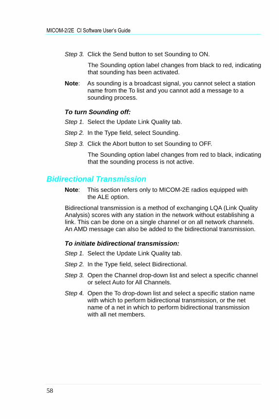
Step 3. Click the Send button to set Sounding to ON.
The Sounding option label changes from black to red, indicatingthat sounding has been activated.
Note: As sounding is a broadcast signal, you cannot select a stationname from the To list and you cannot add a message to asounding process.
To turn Sounding off:Step 1. Select the Update Link Quality tab.
Step 2. In the Type field, select Sounding.
Step 3. Click the Abort button to set Sounding to OFF.
The Sounding option label changes from red to black, indicatingthat the sounding process is not active.
Bidirectional TransmissionNote: This section refers only to MICOM-2E radios equipped with
the ALE option.
Bidirectional transmission is a method of exchanging LQA (Link QualityAnalysis) scores with any station in the network without establishing alink. This can be done on a single channel or on all network channels.An AMD message can also be added to the bidirectional transmission.
To initiate bidirectional transmission:Step 1. Select the Update Link Quality tab.
Step 2. In the Type field, select Bidirectional.
Step 3. Open the Channel drop-down list and select a specific channelor select Auto for All Channels.
Step 4. Open the To drop-down list and select a specific station namewith which to perform bidirectional transmission, or the netname of a net in which to perform bidirectional transmissionwith all net members.

MICOM-2E (Enhanced) Operation
59
Step 5. If you want to add a message to bidirectional transmission,select a message from the message drop-down list or type amessage in the message field.
To remove a message from the message field click the Clr Msg button.
Step 1. Click the Send button to start bidirectional transmission.
The bidirectional transmission label changes from black to red,indicating that bidirectional transmission has begun.
Wait until the bidirectional transmission is completed beforeproceeding.
To stop bidirectional transmission:Step 1. Click the Abort button.
The bidirectional transmission label changes from red to black,indicating that bidirectional transmission has been stopped.
Using the StackNote: This section refers only to MICOM-2E radios equipped with
the ALE option.
Unanswered calls in ALE mode are stored in the Stack, which can saveup to 200 calls (depending on the log file size). When at least oneunanswered call is registered, the Stack button in the Link tab isactivated. If the stack is empty, i.e., there are no unanswered calls, theStack button is disabled.
Note: The contents of the Stack are not necessarily identical tothose of the radio cache. The Stack is only updated when theapplication is running and can store up to 200 unanswered calls.

MICOM-2/2E CI Software User’s Guide
60
Viewing the Stack ListTo display the Stack log file, from the View/Change menu, select Stack.
Alternatively, click the Stack button in the Link tab.
A dialog box containing the list of station names and the date and timeof the unanswered calls appears. You can answer these calls directlyfrom the list, delete selected entries or all entries.
If the Stack list window is too small to contain the list of calls, a scrollbar appears on the right hand side of the window, enabling you to scrollthe list.
Figure 20. The Stack List
The following table details the information displayed in the Stack list:
Field Indication
From The caller’s station name
To The called station name
Date The date on which the call was made
Start The starting time of the call
End The ending time of the call
Message The received/transmitted message.
Net number The net number
Channel The channel number
Call type The call type: Station, Net or All Call
RowSelector

MICOM-2E (Enhanced) Operation
61
The Stack List ToolbarThe stack list toolbar enables quick access to commonly usedcommands and dialog boxes. To display or hide the toolbar, selectToolbar from the View/Change menu.
The stack list command buttons are:
DeleteClick this button to delete specific calls that you havemarked. To select multiple records, hold down the[Ctrl] button and click the rows in the row selector.
Delete AllClick this button to delete all unanswered calls.
ReplyClick this button to reply to an unanswered call thatyou have marked (one call only).
HelpClick this button to display on-line help.
CloseClick this button to close the Stack List window.
MICOM-2/2E CI Software User’s Guide
62
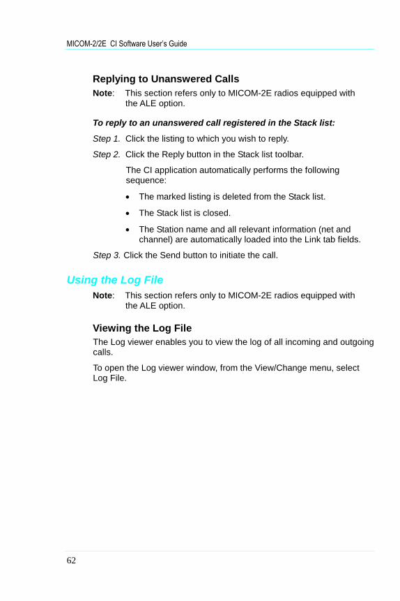
Replying to Unanswered CallsNote: This section refers only to MICOM-2E radios equipped with
the ALE option.
To reply to an unanswered call registered in the Stack list:
Step 1. Click the listing to which you wish to reply.
Step 2. Click the Reply button in the Stack list toolbar.
The CI application automatically performs the followingsequence:
The marked listing is deleted from the Stack list.
The Stack list is closed.
The Station name and all relevant information (net andchannel) are automatically loaded into the Link tab fields.
Step 3. Click the Send button to initiate the call.
Using the Log FileNote: This section refers only to MICOM-2E radios equipped with
the ALE option.
Viewing the Log FileThe Log viewer enables you to view the log of all incoming and outgoingcalls.
To open the Log viewer window, from the View/Change menu, selectLog File.

MICOM-2E (Enhanced) Operation
63
Figure 21. The Log List
The log list contains the following information:
Field Indication
From The caller’s station name
To The called station name
Date The date on which the call was made
Start The starting time of the call
End The ending time of the call
Call type The call type: Station, Net or All Call
Net number The net number
Channel The channel number
Message The received/transmitted message.
If the Log list window is too small to contain the list of calls, a scroll barappears on the right hand side of the window, enabling you to scroll thelist.

MICOM-2/2E CI Software User’s Guide
64
The Log List ToolbarThe log list toolbar enables quick access to commonly used commandsand dialog boxes. To display or hide the toolbar, select Toolbar from theView/Change menu.
The log list command buttons are:
DeleteClick this button to delete specific calls that you havemarked. To select multiple records, hold down the[Ctrl] button and click the rows in the row selector.
Delete AllClick this button to delete all calls.
HelpClick this button to display on-line help.
CloseClick this button to close the Log List window.

65
Keyboard Shortcuts
Press For quick access to dialogs and commands...
[Alt] F File
[Alt] F O Open
[Alt] F R Read device
[Alt] F X Exit
[Alt] V View/Change
[Alt] V C Clarifier
[Alt] V N Notch Filter
[Alt] V L Log File
[Alt] V S Stack
[Alt] C Commands
[Alt] C S Squelch on/off
[Alt] C M Monitor on/off
[Alt] C N Noise Blanker on/off
[Alt] C A Attenuator on/off
[Alt] C C Clipper on/off
[Alt] C R Reset
[Alt] P Preferences
[Alt] P T Window Title
[Alt] P P COM Ports
[Alt] P S SelCall Option
[Alt] P A ALE Option
[Alt] W Window
[Alt] H Help
[Alt] H C Contents
[Alt] H S Search for help on...
[Alt] H A About


68P02950C35-B
@68O2950C35@