to - apps.dtic.mil
TRANSCRIPT
UNCLASSIFIED
AD NUMBER
CLASSIFICATION CHANGESTO:FROM:
LIMITATION CHANGESTO:
FROM:
AUTHORITY
THIS PAGE IS UNCLASSIFIED
ADA800631
unclassified
restricted
Approved for public release; distribution isunlimited.
Distribution authorized to DoD only;Administrative/Operational Use; 14 APR 1947.Other requests shall be referred to NationalAeronautics and Space Administration,Washington, DC. Pre-dates formal DoDdistribution statements. Treat as DoD only.
NASA TR Server website; NASA TR Server website

Reproduction Quality Notice
This document is part of the Air Technical Index[ATI] collection. The ATI collection is over 50 yearsold and was imaged from roll film. The collection hasdeteriorated over time and is in poor condition. DTIChas reproduced the best available copy utilizing themost current imaging technology. ATI documentsthat are partially legible have been included in the DTIC collection due to their historical value.
If you are dissatisfied with this document, please feelfree to contact our Directorate of User Services at[703] 767-9066/9068 or DSN 427-9066/9068.
Do Not Return This Document To DTIC

Reproduced by
AIR DOCUMENTS DIVISION
^ii^ijili^^iiilüliiiiiiiiüüiüi:!!:
miJSism ^ -'•"iii.liilil
JiiS •';;i'.'j" life?.
'pfeife. ^%/4*;::"j|.. ;,•••??
HEADQUARTERS AIR MATERIEL COMMAND
WRIGHT FIELD, DAYTON, OHO
f >
W* 1
USGOVERNMENT IS ABSOLVED
FROM ANY LITIGATION WHICH MAY
ENSUE FROM THE CONTRACTORS IN -
FRINGING ON THE FOREIGN PATENT
RIGHTS WHICH MAY BE INVOLVED.
wi>l *mt IHJ


RESTRICTEIT
Copy No. t-£
RM No. L6J04
NACA
RESEARCH MEMORANDUM r**%
4vxvv.
' A LOW-SPEED INVESTIGATION OF AN ANNITt.AR
TRANSONIC AIR INLET
By
Mark R. Nichols and Donald W. Rinkoski
Langley Memorial Aeronautical Laboratory Langley Field, Va.
A'.S DOCUMENTS DIVISION, T-2 EIGHT FIELD
- l«n u proklklta« ly tow. MICROFILM No
MufeirtMi pMTMUp'okiktt«« tor to*. I ^—* , ./--v
•HUH Of OW UHM UN, «pNtrtowl |\ V_
tfcmfe. Hi la IMMWtMmtUlSmof MMM
=>/T: /Ö7
NATIONAL ADVISORY COMMITTEE FOR AERONAUTICS
WASHINGTON
April 14, 1947
I I
RESTRICTED
MCA EM Ho. USjOk KESraiCTED
RATIONAL ADVISORY CCMCOTEB FOR AERONAOTICS
6) RESEARCH KäMORAMDTM
A LCV-3PESD INVESTIGATION QF AN ANNULAR
TRANSONIC AIR INLET
By Mark E'. Nichols and Donald W. Rinkoaki
SWMARY
K it
I I
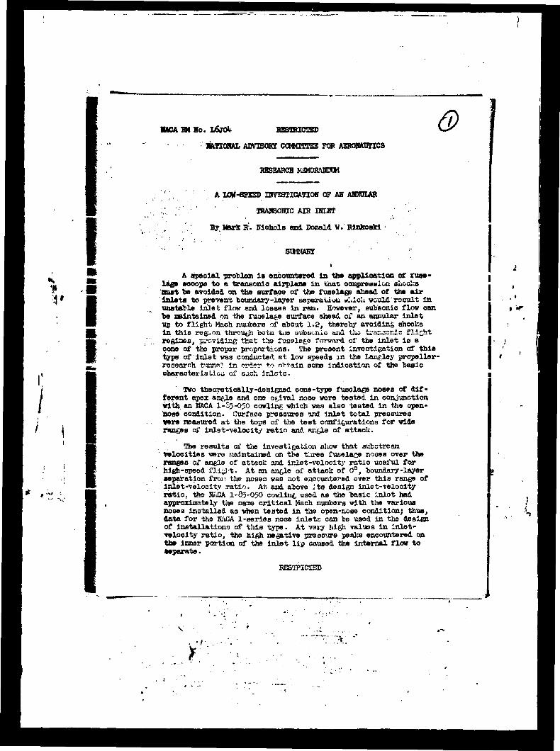
A special problem is encountered in the application of fuse- lage scoops to a transonic airplane in that oompreaalott shocks oust be avoldod on the surf ace of the fuselags ahead of the air Inlets to prevent boundary-layer separation w:»ich weald rssuit is unstable inlet flov end losses in ram. However, sub'sonio flow can be maintained on the fuoela^e surface ahead of an annular inlet up to flight Mach nuuhers of about 1.2, thereby avoiding, shocks in this region throng "ootii tije uubuonlc and tho tosisscic flitfit regimes, providing that t>.s fuselage forward of the inlet is a cone of the proper proportions. The present inveotigation of this typo of inlet was conducted at low speeds in the Lancley propeller- roooarnh tunnel in order to nhtain aon» indication of the basic characterla Lieu of such inlets.
Two theoretically-designed cone-type fueolaee noses of dif- ferent apex an&le and one o^ival nose wore tested in conjunction with an MACA I-S5-050 cowline which was alao tested in the open- nose condition. Curfaoe pressures and inlet total pressures were measured at the tops of the teBt configurations for vide ranfies of inl9t-velocit/ ratio and ar.&le of attack.
The results of the investigation show that aubstream ' velocities were Maintained on the tiree fueelate noses over the
ranges of angle of attack and inlet-velocity ratio useful for high-speed fli^lt. At an angle of attack of 0°, boundary-layer separation from the nosea was not encountered over this range of Inlet-velocity ratio. At end above its design inlet-velocity ratio, the NA.CA I-85-05O cowllnc, used as the basic inlet had approximately the oaao critical Mach numbers with the various noses installed as when tested in the open-nose condition; thus, data for the KAGA 1-series no3e inlete can be used in the design of Installations of this type. At very high values in inlet- veloolty ratio, tho high negative pressure peaks encountered on the Inner portion of the inlet lip caused the internal flow to separate.
RESTRICTED

MCA IM Ho. L&TOlt
IKOtüEUUTION
I
/
# J -%f -,
The use of fuselage scoops offers several important advan- tages In the arrangement of a fighter-type airplane. First, the dusting to the engine nay be made as short as possible; second, good visibility may be obtained by locating the pilot ahead of the Inlets in a thin section of the fuselage; third, the gun installa- tions may be located in the nose where they will not interfere with the air inletB or ducting; and fourth, the directional stability may be improved by reducing the lateral area forward of the center of gravity.
A special problem is encountered in the application of fuse- lage scoops to a transonic airplane in that compression shocks must be avoided on tliö surface of the fuiielae» ahead of the air inlets to prevent boundary-layer separation which would result in unstable inlet flow and losses in ram. This condition can be fulfilled only by Maintaining the velocity of the flow on this surface at subsonic values throueiiGul the jpüe& rurigo of tLe airplane. Xt appears that if the fuselage forward of the inlet is a cone of the correct apex angle, the desired subsonic velocities will be maintained on its surface up to Mach numbers of about 1.2, with low total-pressure losses, and the inlet lip at the base of the cone will operate essentially in th« subu^nie regiree.
Because of the great interest in these inletB and the dif- ficulty of detailed transonic testing at adequate Beynolds numbers, a preliminary study of such designs has been laade at low speeds in the Langley propeller-research tunnel as a part of the current NACA air-inlet research. Obviously many important phenomena associated with compressibility were thereby not observed; however, it was considered that the study would indicate many of the basic characteristics of such inlets. In the present paper are reported studies of the pressure distributions and inlet-flow conditions for annular Inlets consistinc, of an MCA 1-serles nose Inlet (reference 1) around two theoretically-designed cone-type noses of different apex angle and one ofcival nose, toother with comparison tests of the inlet in the open-nose condition. A subsequent report will describe tests in which a canopy and wheel- well fairing were added to the test model to provide a twin-side- scoop configuration applicable to a fighter-type airplane.
SXMBOIS
I Ai Islet area, 1.12 square feet
D mwrHimm diameter of cowling, 27*2? Inches
>

HACA IM NO. LoJOt
I •
I
I
I f M •-'
h height of Inlet, 2.1)7 Inches
E total pressure, pounds per square foot
Mcr predicted critical Mach number
p static pressure, pounds per square foot
p0 static pressure of free stream, pounds per square foot
qQ dynamic pressure of free stream, pounds per square foot
u local velocity at point in boundary layer, feet per second
TJ v»loolty J'.trrt ?utslie Twiasüaiv lower, feet per second
Vj average velocity of flow «t inlet, feet per second
70 velocity of free stream, feet per second
z horizontal distance from station 0 (nee fi£. 2), inches
a ancle of attack of center line of model, degroes
B 'boundary-layer thlclmoas, the normal distance from surface
to point where - •• • = O.98, inches %
MODEL AMD TESTS
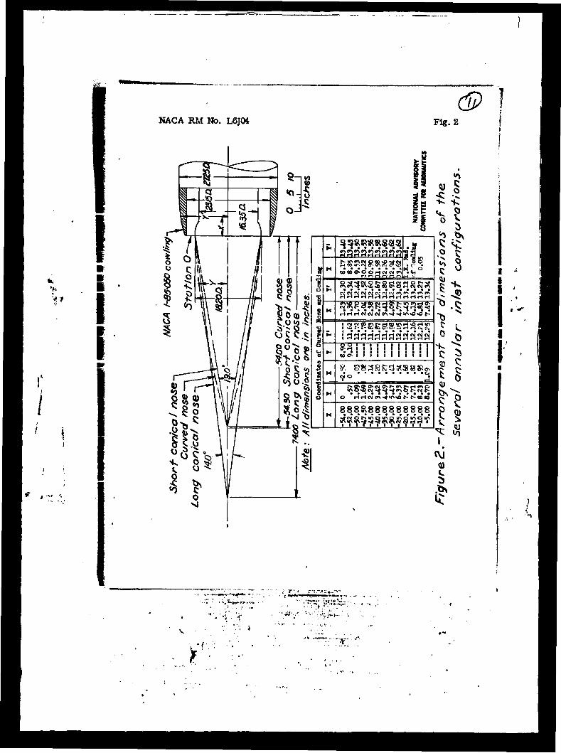
General views of the model are shown as figure 1; line drawings of the three annular-inlet configurations and coordinates of the "ourved" nose and of the HACA 1-05-0*50 nose inlet used In conjunction with each of the funela&e noses are given In figure 2. The three fuselage noses had tho same maximum diameter at the inlet. The "short" conical nose had an apex englo of 19° and a ratio of length to diameter of about 3, while the "long" conical nose hud an apex aufaiu ox' lit0 and a ratio of length to diameter of approxi- mately h. The curved noso which had approximately the same length as the short conical nose we? designer!, to obtain increased volume vlthin the nose; its nose angle was about 32°.
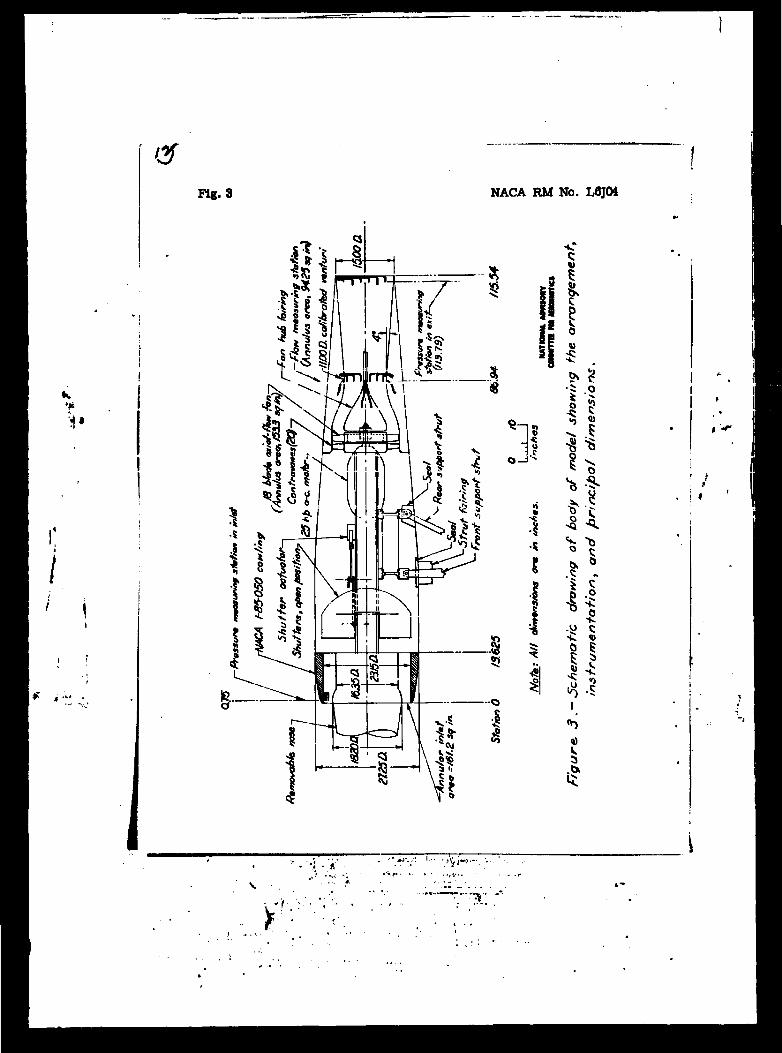
A schematic drawing of the body of the model showing the arrangement, instrumentation, and principal dimensions Is presented as figure 3. The internal-flow system Included an axial-flow fan
I
-J
>

K »-• a
3 *
HACA IM No. L6J0U
whloh «as necessary to obtain the higher inlet-velocity ratios* Flow control vaa obtelned by varying tha speed of the motor and. tha position of the shutters. The quantity of internal flow was measured V means of rakes of total- and. static-pressure tubes at the throat of the venturi and at the exit of the model.
Surface pressures were measured, by means of 11 to 15 flush orlflcos distributed along the top center line of each nose and 21 orifices installed, in the top section of the inlet lip. Total pressures in the boundary layers of the several noses at the entrance station were measured by the use of a removable rate of nine 0.030-inch-diaaetor stainloss-steel tubes with ends flattened to form openings abuut 0.00f> by 0.05 inch. Pressure recoveries in tt» flow adjacent to the inner surf;\ce of the top section of the inlet lip were measured b;- mans of the rake of five l/l6-lnch« diameter total-pressure tubes shown in finure 3. All pressures were recorded by phoxoGrapuiiik a LuiliWuo laainjuaim. •
The three annular-inlet configurations were tested over the angle-of-attack rsjioe fr"!" -2° to n° et inlet-velocity ratios ranging from O.U to 1.5, while the open-nose cowling was Investi- gated over the angle-of-attack range from 0° to 6° at Inlet- velocity ratios ranging between 0.3 and 0.9. All tests were oonductei at t>jsrr.e! srioeds of from 70 to 100 miles Tier hour; the latter value corresponds to a Mach number of 0.13 and a Reynolds number of about 2 million based on the maxiiiium cowling diameter.
» -"
i- '
RjäSUW'3 ASO) MüOiSiiüH
The results of the present investigation are discussed in three sections which deal separately with surface pressures on the noses, surface pressures on the inlet lip, and flow condi- tions at the inlet.
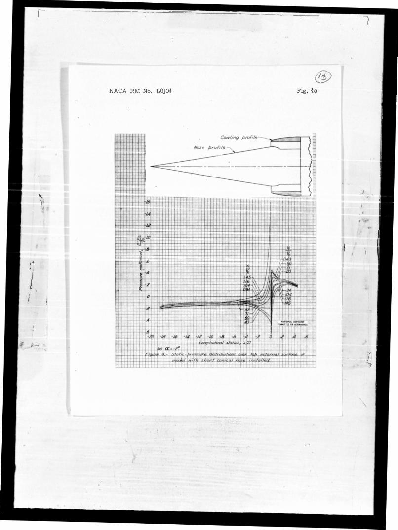
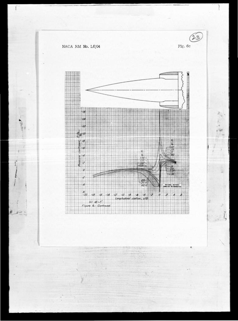
Surface pressures on noses•- Static-pressure distributions over tKa"top external surface of the three inlet configurations are presented in figures k to 6.
The static-pressure distributions over the short conical-nose configuration at an ancle of attack of 0°, figure 't(b), show that substream velocities were obtained over the entire nose for low and medium values of inlet-veloolty ratio. The efrect of increasing, the inlet-velocity ratio was to raise the velocities on the surface of the nose; however, these increases were very small except within one-half oowling diameter ahead of the inlet. Superstream velocltio
w
•• «ma;.;,.;>;,,.
'.<:•. V.
/
1 \
The moro 1— I1P- Müte n°88 * the MSTJSTSM effect of i„, •5 °f ST«O2J *^ Bhort SdLlS** üle angle „, ahead of «.„. ? tile extent oTT. n°Be was to i^f: of attack
ln «• local «i^tt^-PonUag •& toÄ fo1" Velooitio«, the Cotton of- ir0r9asee
aithousj! suw °Ver *• forward « ** nosa-
*"»» iacreane» i^Tf^ «». 4 and |T •?Ml «loae"^^..'1086'
noae ..*- uiaes of the she - w» surface velocities well forward on um •*"«, But «lao roaulted In the foraatiun of a minimum praesure
peak located 0.5 to 1.0 cowling disasters ahead of the lnlat. (Coapare fißs. h and C.) The awfttce ,ilc.uix3es in tto latter region wer» »rrrrsxi^ately fro»-streik values at an Inlet-velocity ratio of 0.9 at an angle of attack of 0°. However, at the usual
- high-speed inlet-velocity ratios, superstreaai velocities did not occur within the useful rante of angle of attack. Surface velocit at the inlet of the curved-nose configuration, ln general, were slightly lower than those for the conlcd-noso configurations at any o'ivon vnlue of Inlet-veloclls' ratio, probably because of the iaproved alinei.ient of the entering flow.
The following table presents the ijaxi lum values of Inlet velocity ratio for which substrean velocities were Maintained the throe noses at angles of attack of 0° and 2°:
on
r t t cone cone
a " 0C
a • 2°
HACA BM No. L6jOU
•
.
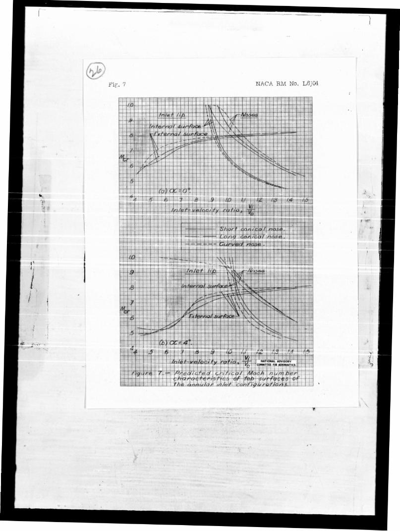
For a =• 2°, the above naxinum values voro determined in the case of the two conical nones by tho pressures on the bottom surfaces ot the inlet, and in the ca3e of the curved nose by the pressures on the top ourfuce of the noso well forward of the inlet. These velocity ratio3 exceed the usual doeirji values for high-speed flight} thereby indicating the feasibility of this type of inlet for a transonic airplana. The critical Mach n\»iber characteristics of the topj surf ."ce3 of the three nosoB (predicted by the use of the von Ksrraan relE.tiünsuip, rofevense 2, and qualified by the fawt that seas of the hipher inlet-velocity ratios are unobtainable in tho high-speed flight conditions due to chokinr; of tho inlet) are presented In figure 7 for the ren<$> of inlet-velocity ratio over which super strewn surface velocities occurred.
Surface pressures on Inlet lip.- The pressure distributions ever t*a rixternäi surf ace of "ttid~iip of the annular inlets (fj gß, U to 6) were eosentj-aiiy bi^-ilEr to thnr.e for tho basic opon-noso ccwliruj (fig. 3), utJL wsyo characteristic of those for the HACA 1-seriea nooe inl->t3 in that they were tlAxlf flüt at trnd above Urn iftlat-voloolts ratios which wara required to prevent the occorroncd of a negative pressure poa«. <%u the leading edge. Tho predicted critical He oh numbe• characteristics} for this surface are shewn in figure 7 as a function of tho inlet- velocity ratio for B&gUia if attack of 0° and h°, and are comparod tD figure 9 at a « 0° with corresponding daca for tho HACA 1-R5-O"50 open-noso covllnc. This comparison shova that at. and above its design inlet-velocity ratio (that is, beyond the "hnee" of the cur»«) the basic inlet had apTiroxiiEe.tel,/ the same critical Mach auiabsrs with the various nonet» Installed .*.s whan tested In tho open-noso condition- Below tiie deuxfjn point, the critical opewtia for the lip of the annular-inlet configurations decreased More gradually with decreases in tho inlet-volocity ratio than did those for the open-nose cowling, probably because the presence of the nones improved the alinement of the entering flow. (See fife. 8.) Tho curved nose produced a hither critical speed on the inlet lip than did the conical noses over most of the rox^e of V-^/VQ for the sana reason. The flow ap-oaore ti have been separated from the
lip of the open-nose cowllnc at — = 0.3 because of the hiöi vo
effective angle of attack of the lip.
The foregoing results indicate that satisfactory lipB for this typo of inlet can bo aaaii?£>i. by arnllofctioa of existing, data for the NACA 1-seriea nose inlets; the design charts of rei'oronco 1 cover the selection of these inlets for critical Mach numbers as nigh as 0.9- In tho use cf thane data it should be noted that the critical Mach nunber io defined as the Mach nusfcer at which sonic
i
I
I
I

NACA RM No. L6J0U
valocity Is attained, on the surface of the nose inlet. Teats of airfoils and streamlined todies indicate that the Mach number at which shock separation and abrupt drafc increases talce place is aome- what greater tlian the critical Mach number.
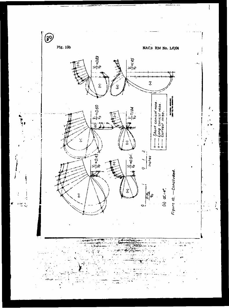
Static-pressure distributions around, the top section of the inlet lip, figure 10, show that negative pressure coefficients occurred on the innido of the lip at inlet-velocity ratios above 0.9 at en ancle of attack of 0°. Both decreases in a and furüier increase in V^/VQ caused rapid, increases in the values of these ne<?atlve pressure coofflciente; the internal flow therefore might be expected, to separate froa the lower lip of the inlet in the climb condition in which combinations of hi£h values of V^/VQ
ana a or» aaooBsbtreA. This result, together with the fact that tie critt?"?. Mp.r?» nurfherfl for this surface were lower than tnose for any other OcnponMxi of the inlet at high values 01 vi/v0
(fiC- 7), stresses the necessity for the experimental development of 163S sensitive inner-lip fairings.
Flow conditions at inlet.- Total^pressure and velocity i^s+r-i>-ut.ions in the boundary layers of the three noaes at the inlet are prosontod in figures 11 and 12, reepouoxvol^. The pro- files are typical of thuue for turbulent flow- TTocroases in the inlet-velocity ratio caused rapid increases in boundary-layer thickness because of the resulting increase» in tho adverse pressure gradient. J.U front of U:2 islet Extensive pressure fluctuations at the recording mano-'ieter furnished an indication thet the boundary
Vi layers on the three noses were unstable at — • O.k; the sample
*o total-pressure and velocity profiles contained in fieures li and 12 show that tho flow was either ooparated or on the verce of separation from the surface of the two conical noses for this test condition.
The boundary-layer thickneGS 6 and the ratio of this thick- ness to the inlet height 6/h are presented in figure 13 aa a function of the inlet-velocity ratio. The boundary-layer thick- nesses for the short conical nose and the curved nose wero of the same order over most of the V^/V0 range, snd were about 19 percent of the inlet height for a typical high-speed inlet-velocity ratio of 0./ compared to about 3a percsnt far the lone r^ninal none. AB the high-speed inlet-velocity ratio for an installation of this type probably would not be less than 0.6, the boundary-layer insta- bility and flow separation mentioned in the precedinc paragraph probably would not be encountered except in the dive condition with the engine throttled.
.«
/

*. •
NACA BM No. lÄTCA
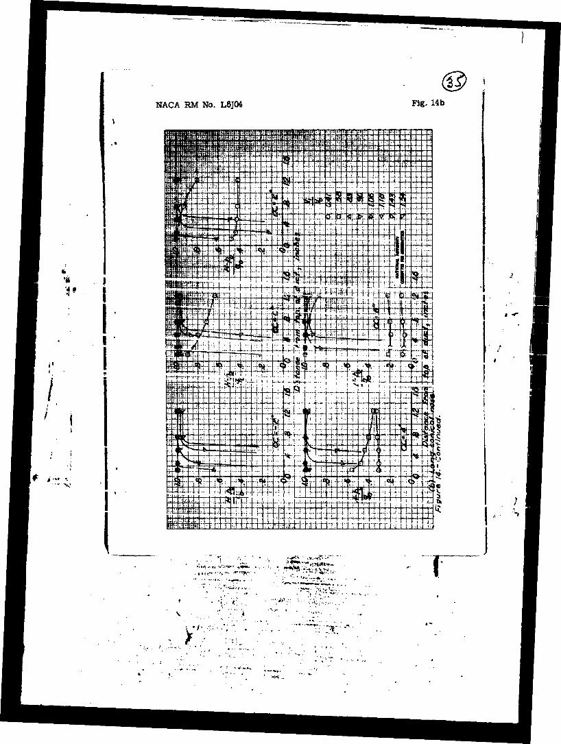
Total pressure recoveries In the outer half of the inlet annulus at the top of the model are shown in figure 1U. The lossea for low inlot-velocity ratios which increased rapidly with angle of attack, were caused by the separated boundary layer on the noses. (See fig. 11 for inner portion Of boundary layer profiles for a • 0°.) The losses for high Inlet-velocity ratios and low angles of attack were caused by separation of the flow from the inner fairing of the lip due to the negative pressure peaks shown in fJjure 10; as separation fron the lip at the bottom of the inlet would be especially severe in tha cliab condition, this result again stresses the necessity for further development of inner-lip fairings for
,+ 1ll^4..
inlet, lip or the ncg«s of the three confic.'rations for inlet- velocity ratios between 0.7 and 1.0. The short, conical nose apueared to have a somewhat wider separation-free operating range of inlet- velocity ratio than did tho other two noseB.
SUMMARY OF RESULTS
A lov-apeod investigation has been made of three transonic fusela&'j-inlet installations designed to ir.livtain svistrean velocities on the bod,,' ahead of the air inlets. The more important results end conclusions of this investigation are summarized as follows:
1. Substream velocitiss were maintained on the three cone-type fuselage noses over the ranges of angle of attack and inlet-velocity ratio useful for high-speed flight.
P.. The thicknesses of the boundary layers on the short and long noses weru about 19 and 32 percent of the inlet height, respectively, for a typical high-speed inlet-velocity ratio of C.?- Boundary-layer soparation was not encountered at an angle of attack of 0° over the range of inlet-velocity ratio useful for high-speed flight.
3« At and above its design inlet-velocity ratio, the NACA 1-85-050 cowling used au the basic inlot had approximately tho same critical Mach numbers with the various noses installed as whsn tested in the open-nose condition. Below this design point, the critical speeds for the inlet lip of the annular-inlet configurations decreased more gradually with decreases in inlet-velocity ratio than did those for tho basic cowling. Thus, data for the KACA 1-serieo nose inlets, which cover the range of critical Mach number up to 0.?, can be used in tha design of installations of this type.

MCA IM Ho. IÄK*
I m m •
I • I
U. At very high values of inlet-velocity ratio the high noga- tlYe pressure peaks encountered on the inner portion of the inlet lip caused, the Internal flow to separate. This result stresses the necessity for the development of leas sensitive inner-lip fairings for inlets which operate at inlet-velocity ratios exceeding unity.
Langley Memorial Aeronautical Laboratory National Advisory Comaittee for Aeronautics
Lancley Field, Va.
REFERENCES
X. Baals, Donald D., Smith, Noriaan F., and Wright, John B.: The Development and Application of Hick-Critical-Speed Nose Inlote. 1WXA /.OR No. L:^30a. 1^5.
2. von I&rman, 35\.: C.-'Bipr&s.niMlity Affects In Aerodyn&nics. Jour. Aoro. Sei., vol. 8, no. 9, July 19^1, PP 337-355.
, «•
\* i- ••
' i • .v.
>:.
"• £;-**}..,

NACA RM No. L6J04 Fig. 1
(a) Short conical none.
(b) Long conical nose.
L
( c ) Curved nose.
Figure 1.- General views of the model with the three annular inlet configurations.
NACA RM No. L6J04 (S> !
Fig. 2
V* I
I \
1 o
1 c n o IB
! o O « «
1 o u
Pi ******** *l* fl
H COCOO^OOiHCVCW fj» «-*
rJrlrinr-.nlM "-
• •«•••••••••• c: « r* c\ w cv r-* <w *n P* ** <*% m
M iH iH r-t CV <V OJ C*\*4-*4U\*0*0 t>
f<
•H 8.9
0
9.10
H
M O I-HIH CV €»>•«* *f>.\0 t*-t^ CO CO
t-i 888Ä888888888
*••>•••••••••
;^Y!^1'r?,^v,i,,y•i,v,
* o
55
J §
SI I
cvi
. £"äwrt.J'i
• '"*• *:
• T'i • ,r "-.-.* L-*.. ri-
•./.;!»>-
*.
:.•-•*-
er Fig. 3 NACA RM No. L6J04
4 .m. i i
V
o 5 0)
'S
*•?
* s ^ 0 -U C
8 *
I
*) 41
i i
"> • Ä ;Ci*->~
Y
NACA RM No. L6J04
<§> Fig. 4a
wmtif

Fig. 4b NACA RM No. L6J04

NACA RM No. L6J04 Fig. 4c
4 #
ifcj a:;«?.*
\ '
£90/; '^'* "J*W iv*"" • *•" •=•'" • Tvr?^vrr^T*rr:r ww^^^''^*' •••""•' r*-f'*-r^'^*^->- •*•%•..«* *•**•-* *#»»*• * i'Mx» "»M li MM—m—-i °
• HHM« ,•• IIS'-'»1
•*.••: . V
*

© Fig. 4d NACA RM No. L6J04

NACA RM No. L6J04 Fig. bb
! \ &*> <ffi\ 1 1 4J • \ ..« • N
•*• ''If i • 1U0BIUTK.I
' % lb)
x> ft -a» 20. •16 -At -A? -a -1) -.* -A £ b -X 4 & longittxtl/sal station , i/B
S • Continued. < t Ü HIi fll I lüSili-rfainth
» I

& Fig. 6c NACA RM N<*. L6J04
ü*
/. 1 i
* i->
> 1
i «r
•••» *
, rr.:tu -*;:rv.' v.
r.-: ••"-.,

/
NACA RM No. L6J04
<S) Fig. 5d
t
K % Zt> «M •& & 16 •/.<> Uf.-U -W :S .ii.
larioilurt/nal station, x/D ki) CC.4-.
0 J A .£
'

Fig. 5e NACA RM No. L6J04
T11+ T
"Jia .-<* -<« -Z2 -x> m m u> tz -a>.-4 -i * ,-.i 4 t
r.Quee 5 ConcKided.
4 A
M —

-•
NACA RM No. L6J04 Fig. 6a
Cowling pror./e-
tttffl" gg
1
1 •
1 1;
%

® Fig. 6b
NACA RM No. L6J04
/
»
>
I
NACA RM No. L6J04 Fig. 6c
*
/
' i
•

@ Fig. 6d
NACA RM No. L6j04
/
r ••

NACA RM No. L6J04
&>
Fig. 6e
I I
l
V
(
/
FiK. 7 NACA RM No. L6J04

• is, •
NACA RM No. L6J04 Fig. 8
I
I
I L

Fig. 9 NACA RM No. L6J04
)m

NACA RM No. L6J04 <2>
Fig. 10a
•
/
u
u c: 0
-*. u 0 Ir, P o 8t» •+* n\ < &,:».
r t Si
1 o i -JO
1 i i 0
1 • ! • O j
O-l
*
V
I I Cgi "*> IE 5 ••
I I
I
|
1 w r
UN
© Fig. 10b NACA RM No. L6J04
' i
I* i -*#
2&S ^^i
1\S •\j
4) <
O-l
1^ c? «
ü c o
4!
t *-
r . * >'
IM'!. . I .
.",'. : .'LS.'iä'x . Mit' w^i i J ii »^»- ~ *-•
^"»^-.^l'' : *• t» |J*
:KT -*•-•-•'*"•:

-4«
4
i I
# •"'" *
1 •
ll
i
t
'(&
NACA RM No. L6J04 Fig. 11
WWa*.**-*;^>-;
.'fc*^*??* \'"
• -.T'
>•
•/• :•

(
@ Fig. 12
NACA RM No. L6J04
I . | -r—7.!-1 'tf-
* ,
lililpilfii
2
II -
(

NACA RM No. L6J04 Fig. 13
TTTT IT? T?T? rar it:"-
*TT FT :" ;i:' TV
:. ••-
, i5fc< »r t con'cit /«!« 'V • ' *TT* .:.
— ~ ..4o< 'St. ...c 0/7/ :o/„ Cnxse1
*-« "jtf
.... — — — — ~ — --J,. !
fl
.... — ._. — .... •-• — ... .... .... ,..
j3 — ~ — .... N ..... .... — — .... .... ... i ;'
-- .... _.. .... — * 6 > ,. i\
i- * [f
rN l:- * .: .1
':£• !'fl
•;.'
hrhn ki" !::; rf- "|v H 1.' :i . ;}:'
.|" LU ft [*'•'
••ig ,« *V *-:4l w.
!'•' «!r
•it < -ii i:f :t. :ij: *** ' !' ~ •*;
•J '4
.2 I
".' '['• *s *<.' 'i: .':;:
i! 'i!i •:i
••L > iL
•• 1 . t i . . . ...
i iß n 1- I
"J 1 A i / 0 iA *• 154- > «f
ZJ .1 / 1, iff *- M m ac /; ^ 1 ae /i 'a. JL
r\£) j
. c; Ot // jß /. 7 fl rJ ̂ r '(7 at yu (r '•tH at » fl 26 "'r1* &: «t 1 frt <er*
// i <7
l/3 J 7/ ii
r? ti & t 'a. U(5 0/ y'i l> ... n: >.* IX. -v X E 0 '_.. NATIONAL ÄBVISODv"
j^
COMMITTEE FO 1 AEMMMUTKS
1 II L^—[.j..l....i....i. ..... i i .: 1 .: .i.... LM. • U-J
J::|:j-
!Si*^iii .***« --V**' ,-vrt«|H-> ••?*"•:-' ,., iif-^r--
1
^

•>«
3'
i
NACA BM No. L6J04 Fig. 14a
mmm^ '•
i «r
I )
^_- •••j*"•**»i*»!»<H.-
•.WVJJK- T
NACA RM No. L6J04 Fig. 14b
V
I I I
4i . • /,' .
••**^*- "lip**•*«.,
1
'/• ;••

VI* «I *
Fig. 14c NACA RM No. L6J04
-i . -1: 4V •,.'-
I ' # '*•
' •
f:
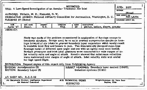
RESTRICTED TITLE: A Low-Speed Investigation of an Annular Transonic Air Inlel
AUTHOR(S]: Nichols, M. R.; RlnkosH, D. W. ORIGINATING AGENCY: National Advisory Commillee for Aeronaullcs, Washington, D. C. PUBLISHED BY: (Same)
fiTO- 3157
'Nm»)
niSUSNIMO AGEMCV MO.
DAX I DOC cum. April '47 \ Reslr.
COOMRY U.S. Eng, 30 I photos, lables, diagrs, graphs
BSTR CT
Study was made of lhe problem encountered in application of fuselage scoops to transonic airplane. Design musl be so as lo prevenl compression shocks on fuse- lage forward of air inlets to prevent boundary layer separation which would resull in unstable lnlel flow and losses in ram. Two theoretically designed cone-lype fuselage noses of different apex angle and one with an oglval nose were lested. Surface pressures and inlet lotal pressure were measured for wide ranges of In- let velocity ralio and angle of attack. Resulls showed that subslream velocities were maintained over ranges of angle of attack. Inlet velocity ratio was useful for high speed flight.
DISTRIBUTION: Request copies of this report only from Originating Agency DIVISION: Aerodynamics (2) SECTION: Boundary Layer (5)
ATI SHEET NO.: R-2-5-12
SUBJECT HEADINGS: Boundary layer conlrol (18400); Induction systems (51401)
Air Decumontt Dlvfelen, lntot)Iponce Departmonl Air Materiel Commend
AIB TECHNICAL IK3EX
RESTRICTED
Wright-PeTtirMm Air Ferce I Dayton, Ofife

4s-
*9^VH fu*.^- ö>. M .UNCLASSIFIED
ATI Revision 3157 " <' (U. S. Military Organizations request copies from ASTIA-DSC. Others request coDies from NACA, Wash. , D. C.)
National Advisory Committee for Aeronautics, Langley Aeronautical Lab., Langley Air Force Base, Va.(NACA TN 2685)
A Low Speed Investigation of an Annular T-ransor.ie Air Inlet - Technical Note
Nichols, MarkR.; Rinkoski. Donald W. 11 Oct'46 (April'52) 38pp. photos, table, diagrs, graphs drwgs
Ducts, Intake - Location Aerodynamics (2)- / Ducts, Intake - Pressure distribution Internal Flow (4) Flow, Transonic r~\
UNCLASSIFIED

RESTRICTED TITLE: A Low-Speed Investigation of an Annular Transonic Air Inlet
AUTHOR|S): Nichols, M. B.; Rinkoskl, D. W. ORIGINATING AGENCY: National Advisory Committee for Aeronautics, Washington, D. C. PUBLISHED BY: (Same)
ßTD- 3157 3, (Mw'nri
_i\U rUBUSHINO AGEMCY NO.
April '47 DOC OMS. Restr.
COUNTST U.S.
1ANOUAOI Eng.
ILLUSTRATIONS
photos, tables, diagrs, graphs ABSTRACT:
Study was made of the problem encountered in application of fuselage scoops to transonic airplane. Design must be so as to prevent compression shocks on fuse- lage forward of air inlets to prevent boundary layer separation which would result in unstable inlet flow and losses in ram. Two theoretically designed cone-type fuselage noses of different apex angle and one with an ogival nose were tested. Surface pressures and inlet total pressure were measured for wide ranges of in- let velocity ratio and angle of attack. Results showed that substream velocities were maintained over ranges of angle of attack. Inlet velocity ratio was useful for high speed flight.
DISTRIBUTION: Request copies of this report only from Originating Agency DIVISION: Aerodynamics (2) SECTION: Boundary Layer (5)
ATI SHEET NO.: R-2-5-12
SUBJECT HEADINGS: Boundary layer control (18400); Induction systems (51401)
Af/ Document» Diviiion, Intolllgonco Daportrnont Air »tiatoriol Command
AIR TECHNICAL INDEX
RESTRICTED
Wrtght-Pattonon Air Fore Dayton, Ohio
JJ_

ATI-3157 REV. 22 July • 52
National Advisory Committee for Aeronautics, 1. Ducts, Intake - Location Langley Aeronautical Lab., Langley Air Force 2. Ducts, Intake - Pressure Base, Va. (NACA TN 2685) distribution
A LOW SPEED INVESTIGATION OF AN ANNULAR 3. Flow, Transonic TRANSONIC AIR INLET - TECHNICAL NOTE, by L Nichols, MarkR. Mark R. Nichols, and Donald W. RinkosM. 11 Oct1 46, n. Rinkoski, Donald W. (April' 52), 38 pp. incL photos, table, diagrs, graphs, drwgs. UNCLASSIFIED
A low-speed investigation of an annular transonic air inlet was conducted in the Langley propeller-research tunnel in order to obtain some indication of the basic
(over)
DIVISION: Aerodynamics (2) SECTION: Internal Flow (4) DISTRIBUTION: U.S. Military Organizations request copies from ASTIA-DSC. Others request copies from ARMED SERVICES TECHNICAL INFORMATION AGENCY NACA, Washington, D.C. DOCUMENT SERVICE CENTER

characteristics of such inlets. Two theoretically designed cone fuselage noses of different apex angle, and one ogival nose were tested in conjunction with an NACA 1-85-050 cowling which was also tested in the open-nose condition. Surface pressures and inlet total pressures were measured at the tops of the test configurations for wide ranges of inlet-veloci- ty ratio and angle of attack. The results of the in- vestigation show that substream velocities were maintained on the three fuselage noses over the ranges of angle of attack and inlet-velocity ratio useful for high-speed flight. At very high values of inlet-velocity ratio, the high negative pressure peaks encountered on the inner part of the inlet lip caused the internal flow to separate. A discussion of the results is included.
ATI-3157