to accompany the 2010 edition of the standard specifications roads and...
TRANSCRIPT

TO ACCOMPANY THE 2010 EDITION OF THE STANDARD SPECIFICATIONS
Roads and Bridges
V. 20150102

~ i ~
SECTION DESCRIPTION PAGE #
DIVISION 100
102 BIDDING REQUIREMENTS AND CONDITIONS 1
102.10 Withdrawal of Proposals 1
102.16 Pre-Construction Data 1
104 SCOPE OF WORK 2
104.12 Value Engineering Change Proposal
and Practical Design Change
Proposal
2
107 LEGAL RELATIONS AND RESPONSIBILITY TO
PUBLIC
5
107.1 Laws To Be Observed 5
107.2 Permits, Licenses, and Taxes 5
107.14 Responsibility For Damage Claims 5
107.21 Protection of Rivers, Streams, and
Impoundments
6
107.21.1 Erosion and Sedimentation Control 6
108 PROSECUTION AND PROGRESS 9
108.3 Prosecution of the Work 9
109 MEASUREMENT AND PAYMENT 22
109.9 Price Adjustment of Fuels 22
109.10.1 Table-Price Adjustment of Asphalt
Binder
22
DIVISION 200
203 DISMANTLING STRUCTURES 27
203.1 Description 27
203.3 Construction Methods 27
207 EXCAVATION AND EMBANKMENT 27
207.6.5 Construction/Demolition Waste
Material
27
207.9 Subgrade 29
207.9.1 Tolerance 29
211 BORROW EXCAVATION 30
211.2 Materials 30
211.2.4 Impervious Core 30
211.3 General 30
211.3.1 Borrow Within WVDOH R/W Limits 30
211.3.2 Borrow Outside WVDOH R/W
Limits
31

~ ii ~
SECTION DESCRIPTION PAGE #
211.3.3 Impervious Core 31
211.5 Rock Borrow Excavation 31
218 SLOPE AND FOUNDATION PROTECTION 33
218.4.1 Scour Protection 33
218.7 Pay Items 33
DIVISION 300
311 OPEN GRADED FREE DRAINING BASE COURSE 35
311.2 Materials 35
311.4 Composition of Optional Stabilizing
Mixtures
35
311.11 Curing 35
DIVISION 400
401 BITUMINOUS ASPHALT BASE, WEARING, AND
PATCHING AND LEVELING COURSES
37
402 BITUMINOUS ASPHALT SKID RESISTANT
PAVEMENT
60
408 TACK COAT
408.9 JOINTS 60
DIVISION 500
501 PORTLAND CEMENT CONCRETE PAYMENT 63
501.1 Description 63
501.4 Testing 63
501.4.4 Testing for Opening Pavement to
Traffic
63
501.4.5 Compressive Strength Tests for
Acceptance
63
501.6 Preparation of Grade, Setting Forms,
and Conditioning of Subgrade or
Base
64
501.6.3.1 Conditioning of Surfaces Receiving
an Unbonded Concrete Overlay
64
501.9 Placing Concrete 64
501.11 Joints 65
501.11.1 Longitudinal Joints 66
501.11.2 Transverse Expansion Joints (Type B
or Type C Joint)
67
501.11.3 Transverse Contraction Joint 67

~ iii ~
SECTION DESCRIPTION PAGE #
501.11.4 Transverse Construction Joints 67
501.11.5 Coated Dowel Bars 68
501.11.6 Expansion Joints Around Structures 69
501.11.7 Random Cracks 69
501.11.9 Transverse Joints in Concrete
Shoulders
69
501.14 Curing 69
501.14.4 White Pigmented Impervious
Membrane
69
501.16 Sealing Joints 70
501.16.1 Silicone Sealant 70
501.22 Method of Measurement 70
501.23 Basis of Payment 70
501.23.1 General 70
501.24 Pay Items 71
503 SEALING CRACKS IN CONCRETE PAVEMENT 71
503.1 Description 71
503.2 Materials 71
503.3 Construction Methods 71
503.4 Preparation of Material Before Use 71
503.5 Preparation of Joints for Sealing 72
503.6 Equipment for Applying Sealer 72
503.7 Placement Requirements 72
503.8 Method of Measurement 73
503.9 Basis of Payment 73
503.10 Pay Item 73
506 CONCRETE PAVEMENT REPAIR 73
506.1 Description 73
506.2 Materials 74
506.3 Proportioning 74
506.4 Testing 75
506.5 Equipment and Tools 75
506.6 Construction Methods 75
506.6.1 Removal of Existing Pavement 75
506.6.2 Conditioning Existing Subbase 76
506.6.3 Placing Concrete 76
506.6.4 Straighedge Checking and Surface
Correction
76
506.6.5 Curing 77
506.6.6 Sealing Joints 77
506.6.7 Repair of Adjacent Shoulders 77
506.6.8 Specific Construction Methods 77
506.6.8.1 Type I Repairs 77

~ iv ~
SECTION DESCRIPTION PAGE #
506.6.8.2 Type II Repairs 78
506.6.8.3 Type III Repairs 79
506.7 Ride Acceptance 80
506.8 Method of Measurement 80
506.9 Basis of Payment 80
506.10 Pay Items 81
509 RE-SAWING AND SEALING LONGITUDICAL
CONCRETE PAVEMENT JOINTS
81
510 RE-SEALING CONCRETE PAVEMENT JOINTS 81
510.1 Description 81
510.2 Materials 81
510.3 Construction Methods 82
510.3.1 Joint Preparation 82
510.3.2 Joint Sealing 82
510.4 Method of Measurement 83
510.5 Basis of Payment 83
510.6 Pay Items 83
514 ROLLER COMPACTED CONCRETE 83
DIVISION 600
601 STRUCTURAL CONCRETE 101
601.1 Description 101
601.2 Materials 101
601.3 Proportioning 102
601.3.1 Mix Design Requirements 102
601.3.2.3 Yield 103
601.3.2.4 Total Solids Ā 103
601.4 Testing 104
601.4.1 Sampling and Testing Methods 104
601.4.2 Contractor‟s Quality Control 104
601.4.5 Tests for permeability acceptance of
Class H Concrete
104
601.7 Mixing 105
601.8 Forms 105
601.8.1 General 105
601.8.7 Removal of Forms and Construction
of Superimposed Elements
105
601.8.9 Stay-In-Place Fabricated Metal
Forms for Concrete Bridge Decks
106
601.8.9.4 Placement of Concrete 106
601.10.1.1 Pre-Pour Meeting 106
601.10.1.2 Concrete Placement Limitations 106

~ v ~
SECTION DESCRIPTION PAGE #
601.10.1.3 Concrete Placement at Night 107
601.11 Finishing Concrete Surfaces 107
601.11.4 Finishing Concrete Bridge Decks 107
601.11.4.1 Class K Bridge Decks 107
601.11.4.2 Class H Bridge Decks 108
601.11.4.3 Straightedge Testing of Hardened
Bridge Decks
108
601.11.4.4 Class H Concrete Finished Deck
Grooving
109
601.11.4.4.1 Transverse Grooving 109
601.11.4.4.2 Longitudinal Grooving 109
601.12 Curing and Protecting Concrete 111
601.12.1 Curing Under Normal Conditions 111
601.12.3 Protection of Finished Surfaces 111
601.12.4 Curing Class H Concrete 111
601.12.5 Protecting Concrete Decks 112
601.13 Protective Surface Treatments 112
601.13.1 Silane Treatment for Bridge
Superstructure
112
601.13.1.1 Silane Treatment for Bridge
Substructure
112
601.13.3 Concrete Protective Coating 113
601.13.3.1 Concrete Surface Preparation 113
601.14 Method of Measurement 113
601.15 Basis of Payment 114
601.15.1 General 114
601.16 Pay Items 114
602 REINFORCING STEEL 115
602.6.1 General 115
602.7.1 Lapping 115
603 PRESTRESSED CONCETE MEMBERS 116
603.6.5 Strength of Concrete 116
603.14.2.1 Price Adjustments 116
603.15 Pay Items 117
606 UNDERDRAINS 117
606.2 Materials 117
607 GUARDRAIL 117
607.2 Materials 117
610 PLAIN CONCRETE CURBING, INTEGRAL
CONCRETE CURBING, AND COMBINATION
CONCRETE CURB AND GUTTER
113
610.3.4 Sections 117
614 PILING WALLS 118
614.8 Method of Measurement 118

~ vi ~
SECTION DESCRIPTION PAGE #
615 STEEL STRUCTURES 118
615.3 Materials 118
615.3.2 High-Strength Fasteners 118
615.3.2.1 Weathering Steel Bridges 118
615.3.7 Coating of Anchor Bolts, Nuts and
Washers
118
615.4 Fabrication 119
615.4.2 Storage of Materials 119
615.5 Assembly 119
615.5.7 Welding 119
615.6 Erection 119
615.6.9 Final Cleaning of Weathering Steel
Bridges
120
620 THREE-SIDED REINFORCED CONCRETE
BRIDGE/CULVERT
120
620.2 General 120
625 DRILLED CAISSON FOUNDATIONS 121
625.4.1 Concrete 121
626 RETAINING WALL SYSTEMS 121
626.5 Materials 121
626.5.1.1.2.3 Sealers 121
626.5.3.1 Test Requirements 121
633 CONCRETE GUTTER, INVERT PIPE GUTTER, OR
DUMPED ROCK GUTTER
122
633.2 Materials 122
633.6 Dumped Rock Gutter 122
633.6.1 Grout for Dumped Rock Gutter 122
633.7 Method of Measurement 122
633.9 Pay Items 122
636 MAINTAINING TRAFFIC 122
636.5 Temporary Structures 123
636.12 Temporary Impact Attenuating
Device
123
636.14 Temporary Barrier 124
636.14.1 Materials 124
636.14.2 Installation 124
636.15 Removing and Resetting Temporary
Barriers
125
636.23 Method of Measurement 125
636.23.4 Temporary Structures 125
636.23.17 Temporary Barrier 126
636.23.18 Removing and Resetting Temporary
Barrier
126
~ vii ~
SECTION DESCRIPTION PAGE #
636.23.27 Temporary Impact Attenuating
Device
126
636.23.28 Remove and Reset Attenuator Device 126
636.25 Pay Items 127
638 PROJECT MARKERS, RIGHT-OF-WAY
MARKERS, SURVEY MARKERS, AND OUTLET
MARKERS
128
638.1 Description 128
638.2 Materials 128
638.6 Outlet Markers 128
638.6.1 General 128
638.6.2 Location and Content 129
638.6.3 Installation 129
638.7 Method of Measurement 129
638.8 Basis of Payment 130
638.9 Pay Items 130
640 FIELD OFFICE AND STORAGE BUILDING 130
640.4.1 General 130
642 TEMPORARY POLLUTION CONTROL 131
642.6 Temporary Pipe, Contour Ditches,
Berms, Slope Drains, Ditch Checks
& Silt Fence, Premanufactured Ditch
Checks & Super Silt Fence
131
642.6.8 Super Silt Fence 131
642.7 Method of Measurement 131
642.8 Basis of Payment 131
642.9 Pay Items 132
657 ROADSIDE SIGN SUPPORTS 133
657.2 Materials 133
657.2.5 U-Channel Breakaway Mounting
Device
132
657.4.2 Setting Posts 132
657.5.12 U-Channel Breakaway Mounting
Device
132
660 TRAFFIC SIGNALS 133
660.2 Materials 133
660.9 Loop Traffic Detectors 133
660.10 Signal Heads 133
660.10.1 Light Emitting Diode Signal Modules
(L.E.D.)
133
660.15 Junction Boxes 136
660.19 Method of Measurement 136
660.19.10 Priority Control System Emitter 136
660.19.11 Priority Control System Detector 136
~ viii ~
SECTION DESCRIPTION PAGE #
660.21 Pay Items 137
661 TRAFFIC SIGNS AND DELINEATORS 137
661.3.7.1 Flat Sheet 137
661.17 Pay Items 137
662 ROADWAY LIGHTING 138
662.11 Lighting Supports 138
662.14 Testing 138
664 TRAFFIC SAFETY DEVICES RUBLE STRIPS 138
664.2 Materials 138
664.3 Construction Methods 139
664.3.1.1 Crash Cushion, Quad Guard
Terminal Devices, Reusable Energy
Absorbing Crash Terminal, Trinity
Attenuating Crash Cushion, SCI
Impact Attenuating, and TAU-11
Impact Attenuating Devices
139
664.3.2 Rumble Strips 139
664.3.2.1 Rumble Strip Equipment 140
664.4 Method of Measurement 140
664.4.2 Rumble Strips 140
664.5 Basis of Payment 140
664.6 Pay Items 140
679 OVERLAYING OR PORTLAND CEMENT
CONCRETE BRIDGE DECKS
141
679.2.2 Specialized Concrete Mix Design and
Testing
141
679.2.2.1 Latex Modified Concrete 141
679.2.2.2 Microsilica Concrete 142
679.2.2.4 Test Slab Requirements 142
679.3 Construction Methods 142
679.3.1.1 Removal of Existing Deck Surface
Phase I
142
679.3.1.2 Removal of Existing Deck Surface
Phase II
143
679.3.1.2.1 Full Depth Removal of Materials 143
679.3.1.4 Disposal 143
679.3.7.5.1 Curing Latex Modified Concrete 144
679.3.7.5.2 Curing Microsilica Concrete 144
679.6 Method of Measurement 144
679.6.2.2 Untitled Section 144
679.6.2.3 Full Depth Removal 144

~ ix ~
SECTION DESCRIPTION PAGE #
DIVISION 700
701 HYDRAULIC CEMENT 147
701.3 Blended Hydraulic Cements 147
707 CONCRETE ADMIXTURES, CURING AND
COATINGS MATERIALS
147
707.9 Liquid Membrane-Forming
Compounds for Curing Concrete
147
707.15 Hydration Control Stabilizing
Admixtures for Concrete
147
707.15.1 Acceptance Requirements for
Approval of Hydration Control
Stabilizing Admixtures
147
707.15.2 Performance Requirements for
Concrete Hydration Control
Stabilizing Admixtures
147
707.15.3 Certification of Hydration Control
Stabilizing Admixtures
148
707.14.4 Additional Test Requirements for
Hydration Control Stabilizing
Admixtures (Optional)
148
707.17 Specific Performance Admixtures for
Concrete
148
707.17.1 Acceptance Requirements for
Approval of Specific Performance
Admixtures
148
707.17.2 Performance Requirements for
Concrete Accelerators
148
707.17.3 Certification of Specific Performance
Admixtures
149
707.17.4 Additional Test Requirements for
Accelerating Admixtures (Optional)
149
708 JOINT MATERIALS 149
708.2 Preformed Elastomeric Joint Seals;
Lubricant-Adhesives
149
708.2.2 Joint Seals for Bridges 149
709 METALS 149
709.51 U-Channel Breakaway Mounting
Devices
149
709.51.1 General Description and
Requirements
149
709.51.2 General Design and Functionality 150
709.51.3 Individual Component Features 150
709.51.3.1 Breakaway Coupler 150
~ x ~
SECTION DESCRIPTION PAGE #
709.51.3.2 Anchor 151
709.51.3.3 Receiver 151
709.51.4 Component Materials and Coatings 151
710 WOOD MATERIALS 151
710.1 Structural Materials 151
710.2 Species and Grade 152
710.3 Preservative Treatment 152
710.4 Treatment Plants 152
710.4.1 Certified Plants 152
710.4.2 Noncertified Plants 152
710.5 Wood Posts 153
710.6 Plywood 153
710.7 Common Lumber 154
710.8 Service and Lighting Poles 154
714 CONCRETE, CLAY, FIBER AND PLASTIC
CULVERTS
154
714.23 Precast Reinforced Concrete Box
Culverts
154
715 MISCELLANEOUS MATERIALS 154
715.6 Hydrated Lime 154
715.6.1 General Use 154
715.6.2 Soil Stabilization or Pavement
Preservation Purposes
154
715.8 Waterproofing Fabric 154
715.10 Prefabricated Drainage Systems 155
715.10.1 Prefabricated Pavement Edge Drain 155
715.10.1.1 General 155
715.10.1.2 Core 155
715.10.1.3 Fabric 155
715.10.1.4 Fittings 155
715.10.1.5 Outlet Pipe 155
715.10.1.6 Acceptance 155
715.11 Engineering Fabric 156
715.11.1 General 156
715.11.2 Acceptance 156
715.11.3 Maintenance and Repairs 156
715.11.4 Engineering Fabric for Subsurface
Drainage
156
715.11.5 Engineering Fabric for Sediment
Control (Silt Fence)
156
715.11.6 Engineering Fabric for Erosion
Control
156
715.11.7 Engineering Fabric for Paving 156
715.11.8 Engineering Fabric for Separation 156

~ xi ~
SECTION DESCRIPTION PAGE #
715.11.9 Engineering Fabric for Stabilization 157
715.11.10 Engineering Fabric for Pumped
Sediment and Erosion Control
(Dewatering Device)
157
715.12 Concrete for Miscellaneous Users 157
715.14 Elastomeric Bearing Pads 158
715.14.1 Sampling Frequency for Elastomeric
Bearing Pads
158
715.40 Pavement Marking Material 158
715.40.6 Raised Pavement Markers (RPM‟s) 158
715.40.6.1 Type P-2 Markers 158
715.40.6.1.1 Casting Requirements 159
715.40.6.1.2 Lens Requirements 160
715.40.6.1.3 Adhesive Requirements 161
715.40.6.1.4 Product Submission and Approval 161
715.40.6.2 Type R-4 Markers 162
715.40.6.2.1 Adhesive Requirements 164
715.40.6.2.2 Product Submission and Approval 164
715.40.6.3 Temporary Markers 165
715.41 Traffic Safety Devices 165
715.41.4 Quad Guard Impact Attenuating
Device (Type VIII)
165
715.41.7 SCI Impact Attenuating Device (Type
III) 166
715.41.7.1 Description 166
715.41.7.2 Performance 166
715.41.8 TAU-II Impact Attenuating Device
(Type IX)
167
715.41.8.1 Description 167
715.41.8.2 Performance 168
715.41.9 Acceptance 168
715.42 Traffic Signal Materials and
Equipment
168
715.42.7 Preemption 168
715.42.7.4.1 Implementation 168
715.42.7.4.1.1 Optical Emitter 169
715.42.7.4.1.2 Detector 169
715.42.7.4.1.3 Card Rack Mounted Interface Unit 169
715.42.7.4.1.4 Control Equipment 169
715.42.7.4.1.5 System Requirements 169
715.42.7.4.1.6 Warranty 170
715.42.7.4.1.7 Codes and Basis of Payment 170


~ 1 ~
DIVISION 100
GENERAL PROVISIONS
SECTION 102
BIDDING REQUIRMENTS AND CONDITIONS
102.10 - WITHDRAWAL OF PROPOSALS:
DELETE THE CONTENTS OF THE SECTION AND REPLACE WITH
THE FOLLOWING:
Bidders may withdraw Proposals in a manner approved by the electronic
bidding service provider and the Division prior to the letting.
On projects requiring prequalification, a bidder may alternatively request
to withdraw its bid under the conditions and in the same manner as described for
projects where Prequalification is waived provided the bidder provides written
notice to the Division 2:00PM of the business day preceding the letting and the
bidder receives confirmation from the Division stating the bidder will be allowed
to do so.
For projects where Prequalification is waived, and after the time provided
for the opening of proposals, a bidder may withdraw its bid during the course of
reading of bids prior to the actual reading of bids on the project for which the bid
is withdrawn only by providing a written document at the site of the letting in the
following form:
“I, the undersigned, of ____________________________, Contractor(s)
hereby acknowledge that I have this day withdrawn the sealed bid of
__________________________________________, Contractor(s) on West
Virginia Division of Highways Project No. _____________________.”
Contractors who are found to be low bidders on a number of projects of
which the total exceeds the Contractor's rating may withdraw, with the approval
of the Commissioner, bids on such project or projects as will bring the remaining
total to within the limit of the rating. At their discretion, the Commissioner may
award contracts for the project or projects on which bids have been so withdrawn
to the next lowest qualified bidder.
102.16-PRE-CONSTRUCTION DATA:
ADD THE FOLLOWING SUBSECTION TO THE PROPOSAL:
102.16.1-Questions Regarding Advertised Proposals: All projects
advertised by the Division will require any questions to be asked using the
Question and Answer feature of the electronic bidding service in accordance
~ 2 ~
with any listed requirements. The various contact information required shall
be filled out and completed with valid and applicable information which the
Division may verify. If the contact information is unable to be verified then
any questions associated with this information may not be answered.
Questions and Answers are for informational purposes only. Any posted
questions or answers do not alter the terms and conditions of the advertised
Contract in question. Official changes to the Contract shall only be issued by
the Division through an addendum to the applicable Contract.
Potential Bidders may ask questions up until the time of the posted letting
with no exceptions. However it should be noted that any questions that may
necessitate a change to the Contract should be asked seven (7) days prior to
the posted letting date to allow the Division to issue an addendum to modify
the Contract, if necessary. Questions received three (3) working days or more
in advance of a posted Letting should be answered prior to the time of the
posted letting. Questions received within three (3) working days of the posted
time of Letting may or may not be answered as time allows.
SECTION 104
SCOPE OF WORK
104.12-VALUE ENGINEERING:
DELETE THE TITLE AND CONTENTS OF THE SECTION AND
REPLACE WITH THE FOLLOWING:
104.12-VALUE ENGINEERING CHANGE PROPOSAL AND
PRACTICAL DESIGN CHANGE PROPOSAL:
The Contractor may submit to the Engineer, in writing, Value Engineering
Change Proposals (VECP) for modifying the plans, specifications or other
requirements of the contract for the purpose of reducing the total cost of
construction without reducing design capacity or quality of the finished product.
If accepted by the Division, the cost savings difference between the original
contract work being modified and the final cost of the proposed new work shall be
shared between the Contractor and the Division on a fifty-fifty basis.
The Contractor may submit to the Engineer, in writing, a Practical Design
Change Proposal (PDCP) for modifying the plans, specifications or other
requirements of the contract for the purpose of reducing the total cost of
construction. A Practical Design Change Proposal may provide a finished
product with a justifiably revised scope change, as compared to the as-bid
product. The PDCP may modify construction sequences, re-use existing roadway
elements or underrun contract items. The PDCP shall not adversely affect safety
or function of the final product. The cost savings to the Division shall be
negotiated to be at least 60% of the cost difference between the original contract

~ 3 ~
work being modified and the final cost of the proposed new work listed in the
change order for a PDCP.
The contractor is encouraged to submit to the engineer, in writing,
VECP‟s and PDCP‟s for modifying the plans, specifications or other requirements
of the contract. Proposed modifications should not impair, in any manner,
essential functions or characteristics of the project, including but not limited to,
service life, economy of operation, ease of maintenance, and shall not impair
design or safety standards, and shall not significantly delay the completion of the
project.
This subsection applies to all VECPs / PDCPs initiated and developed by
the Contractor and which are identified as such by the Contractor at the time of
their submission to the Engineer; however, nothing shall be construed as requiring
the Engineer to consider or approve a VECP/PDCP submitted hereunder.
As a minimum, the following information shall be submitted, in
quadruplicate, with each VECP/PDCP along with all information additionally
submitted in electronic format:
i. a statement that this proposal is submitted as a VECP or PDCP;
ii. a description of the difference between the existing contract requirements
and the proposed change;
iii. a statement concerning the basis for the VECP/PDCP and benefits to the
Division together with an itemization of the contract items and
requirements affected by the VECP/PDCP;
iv. separate detailed cost estimates for both the existing contract
requirements and the proposed change;
v. an itemization of plan details, design standards or specifications to be
changed if the VECP/PDCP is adopted;
vi. an estimate of the effect on collateral costs to the Division. Collateral
costs are defined to be reduced costs of operation, maintenance or
repair and extended useful service life; and
vii. a statement of the time by which approval must be issued to obtain the
total cost reduction during remainder of Contract, noting any effect on
contract completion time or delivery schedule;
viii. a description of any previous use or submission of the same proposal by
the Contractor, including dates, job numbers, results, and/or outcome of
proposal if previously submitted;
ix. final submittals for VECPs and PDCPs shall be signed and sealed by a
West Virginia Registered Professional Engineer, and that individual
will become the Engineer of Record for the work described in the
VECP/PDCP.
It should be noted that on a case by case basis, the Contractor may be
required to do presentations to the Division addressing the above issues and
clarifying any additional information requested by the Division.
If approved by the Division, the Division will process the VECP/PDCP in
the same manner as prescribed for any other proposal which would necessitate

~ 4 ~
issuance of a Contract change order. The Division may accept in whole or in part
any VECP/PDCP by issuing a change order which will identify the VECP/PDCP
on which it is based. The Division will not be liable to the Contractor for failure
to accept or act upon any VECP/PDCP submitted pursuant to this provision nor
for any delays to the work attributable to any such proposal. The Division has the
right to reject any VECP/PDCP without explanation. Additionally there may be
other regulatory agencies outside of the Division that may need to review the
proposed VECP/PDCP and have the authority to reject/accept the proposed
VECP/PDCP. The Division accepts no responsibility in delays or costs attributed
to any such reviews by outside agencies and it is the responsibility of the
Contractor to get approval from said organizations.
Until a proposal is effected by change order, the Contractor shall remain
obligated to the terms and conditions of the existing contract. When an executed
change order has not been issued by the date upon which the Contractor's
proposal specifies that a decision should be made, or such other date as the
Contractor may subsequently have specified in writing, such proposal may be
deemed rejected.
The change order affecting the necessary Contract modification will
establish the estimated savings agreed upon, will provide for adjustment in the
Contract prices and will indicate the savings be divided between the Contractor
and the Division as per the negotiated agreements. The Contractor shall absorb
all costs incurred in preparing a VECP/PDCP for submission to the Division. All
reasonably incurred costs of reviewing and administering the VECP/PDCP will be
borne by the Division. The Division reserves the right to include in the change
order any conditions it deems appropriate for consideration, approval and
implementation of the proposal. The Contractor's share of the savings shall
constitute full compensation for effecting all changes pursuant to the change
order.
Acceptance of the VECP/PDCP and performance of the work thereunder
will not change the Contract completion date as a result of the VECP/PDCP,
unless specifically provided for in the change order authorizing the VECP/PDCP.
The Division expressly reserves the right to adopt a VECP/PDCP for
general use in contracts administered by the Division when it determines the
VECP/PDCP is suitable for application to other contracts without obligation or
compensation of any kind to the Contractor.
The Engineer shall be sole judge of the acceptability of a VECP/PDCP.
When a VECP/PDCP is accepted by the Division, the provisions of 104.2
pertaining to adjustment of Contract unit price due to alterations of Contract
quantities will not apply to the items adjusted or deleted as a result of affecting
the VECP/PDCP by change order.
The cost of the revised work, as determined in the value engineering
change order, will be paid on current estimates.
In addition to such payment for VECP items, the Contractor will be paid,
on a Lump Sum basis by a separate item, one half of the difference of the cost of
the original contract work and the final cost of the new work listed in the change
order In addition to such payment for PDCP items, the Contractor shall be paid on
~ 5 ~
a Lump Sum basis by separate item the negotiated contractor portion of the
savings.
For VECP, one half of contractor portion of the estimated savings will be
paid to the Contractor upon approval of the change order. For PDCP, one half of
the negotiated contractor portion of the estimated savings will be paid to the
Contractor upon approval of the change order. The remainder of the savings due
the Contractor will be paid upon completion of all items of work included in the
change order. This final Lump Sum payment will be determined by the actual
quantities for items paid by the unit. Final payment for other lump sum or
proposal quantity items will be the change order amount, subject to 109.2.
SECTION 107
LEGAL RELATIONS AND RESPONSIBILITY TO PUBLIC
107.1-LAWS TO BE OBSERVED:
DELETE THE LAST SENTENCE AND REPLACE WITH THE
FOLLOWING:
The Contractor shall at all times observe and comply with all such laws,
ordinances, regulations, orders and decrees; and shall protect and indemnify,
defend and hold DOH harmless from any and all claims, liabilities and causes of
action for any fines or penalties imposed on DOH by any state or federal agency
because of violation by CONTRACTOR or any of its subcontractors and/or
consultants of any state or federal law or regulation.
107.2-PERMITS, LICENSES, AND TAXES:
ADD THE FOLLOWING PARAGRAPH TO THE SECTION:
The Contractor shall provide the Division with sufficient documentation
that all applicable taxes have been paid within 120 days of the project acceptance
as provided for in 105.16. The Division shall have the right to revoke the
Contractor‟s Prequalification until the Contractor provides sufficient
documentation that all taxes have been paid or are the subject of a timely filed
dispute currently pending in a court or other body having legal authority and
jurisdiction to hear the dispute.
107.14-RESPONSIBILITY FOR DAMAGE CLAIMS:
DELETE THE SECTION AND REPLACE WITH THE FOLLOWING:
107.14-RESPONSIBILITY FOR DAMAGE CLAIMS:

~ 6 ~
The Contractor shall indemnify and save harmless the Division, its
officers and employees, from all suits, actions, or claims of any character brought
because of any injuries or damage received or sustained by any person, persons,
or property on account of the operations of the Contractor, its subcontractors
and/or consultants; or on account of or in consequence of any neglect in
safeguarding the work; or through use of unacceptable materials in constructing
the work; or because of any act or omission, neglect, or misconduct of the
Contractor its subcontractors and/or consultants; or because of any claims or
amounts recovered from any infringements of patent, trademark, or copyright; or
from any claims or amounts arising or recovered under the "Worker's
Compensation Act," or any other law, ordinance, order, or decree; and so much of
the money due the Contractor under and by virtue of their Contract as may be
considered necessary by the Division for such purpose may be retained for the use
of the Division or, in case no money is due, their surety may be held until such
suit or suits, action or actions, claim or claims for injuries or damages as aforesaid
shall have been settled and suitable evidence to that effect furnished to the
Division; except that money due the Contractor will not be withheld when the
Contractor produces satisfactory evidence that the Contractor is adequately
protected by public liability and property damage insurance.
107.21-PROTECTION OF RIVERS, STREAMS, AND IMPOUNDMENTS:
107.21.1-Erosion and Siltation Control:
DELETE THE ENTIRE SUB-SUBSECTION AND TITLE AND
REPLACE WITH THE FOLLOWING:
107.21.1-Erosion and Sedimentation Control:
The Contractor shall be responsible for water quality throughout the
duration of construction in accordance with the National Pollutant Discharge
Elimination System (NPDES) permit registration with the West Virginia
Department of Environmental Protection Agency (WVDEP). The Contractor
will responsible for the following:
i. Developing and implementing an effective erosion and sediment
control plan.
ii. Directing the construction, operation, maintenance and dismantling
of temporary erosion and sediment control features.
iii. Implementing remedial action to correct and/or repair failing
erosion and sediment control features.
iv. Implementing storm and winter shutdown procedures.

~ 7 ~
v. Shaping the earthwork prior to the suspension of grading
operations each day in a manner that will permit storm runoff with
minimum erosion.
vi. Installing, operating and maintaining erosion and sediment control
features in an acceptable condition.
vii. Cleaning out and restoring to original conditions any erosion or
sediment control feature that has reached half of its capacity. For
sediment basins, one half of its capacity is considered as wet
volume storage.
The Contractor shall prepare a Spill Prevention, Control and
Countermeasures (SPCC) plan that itemizes specific measures that will be
implemented to prevent and clean up chemical and petroleum product spills
that may occur during all phases of construction. Fuel storage and refueling
activities, equipment maintenance activities and equipment washing will be
kept at least 500 feet away from any watercourse or wetland.
Any details not shown in the plans shall be in accordance with the latest
version of the West Virginia Division of Highways Erosion and Sediment
Control Manual. In the event that temporary erosion and sediment control
measures are necessary due to the Contractors negligence, carelessness or
failure to install permanent controls as part of the work as scheduled, such
work shall be performed by the Contractor at his own expense.
In addition to the above, the Contractor shall make themselves familiar
with all requirements contained within the WVDEP‟s General Water Pollution
Control Permit, Stormwater Associated with Construction Activities Permit
Number WV0115924. A copy of this permit can be found at the following
internet address:
http://www.dep.wv.gov/WWE/Programs/stormwater
Noncompliance with permit conditions constitutes a violation of the Clean
Water Act and State Code and is subject to enforcement action by the
WVDEP.
At the Project‟s Pre-Construction Conference, the Contractor shall submit
to the Department in addition to the appropriate number of Erosion and
Sediment Control Plans, the Co-Applicant #1 signature page (Exhibit 1) and
the Contractor‟s E&S Manager Contact.
The Contractor‟s E&S Contact shall contain the following information:
the name, title, mailing address and telephone number of the person who will
be responsible for the Erosion and Sediment Control plans, implementation,
maintenance, etc., for the life of the NPDES registration.
Upon completion of the Pre-Construction Conference, the Department will
modify the existing NPDES registration for this project to make the

~ 8 ~
Contractor the number one Co-Applicant to the permit. Once this has been
completed, the Contractor shall be responsible for any and all fees, violations
and fines assessed against the project that is a result of the Contractor‟s
negligence, carelessness, or failure to install permanent controls as part of the
work as scheduled.
Once the project is complete, the Contractor will still bear responsibility
for the NPDES registration until either a Notice of Termination (NOT) is
received from the WVDEP or the Contractor has received final payment for
the project. If an NOT has not been received by the time the final payment is
made, the Department will modify the NPDES registration to remove the
Contractor‟s name from the registration.
The exhibit can be located online at:
http://www.transportation.wv.gov/highways/contractadmin/specifications/
107.21.1EnSExhibit1/Pages/default.aspx
SECTION 107.21.1 EXHIBIT 1
COAPPLICANT #1 SIGNATURE PAGE

~ 9 ~
SECTION 108
PROSECUTION AND PROGRESS
108.3-PROSECUTION OF THE WORK:
108.3.1-General:
DELETE THE SUBSECTION SUBSECTIONS AND REPLACE WITH
THE FOLLOWING:
108.3-PROSECUTION OF THE WORK:
108.3.1-General: The Contractor shall provide sufficient resources
(materials, equipment, and labor, etc.) to guarantee the completion of the
project in accordance with the Plans and Specifications within the time set
forth in the Proposal.
The Contractor shall submit a Detailed Construction Schedule and any
subsequent schedules, as required by this specification, in the form more
clearly defined in section 108.3.2 with all graphic and tabular supporting
documentation, hereinafter referred to as "Schedule.”
Schedules will be required for all projects where the Contract Bid Amount
is greater than $2,000,000. Additionally any Project that contains an
Incentive/Disincentive clause, and all Design Build projects and Public
Private Partnership projects shall require a Schedule.
Unless otherwise specified, Schedules will not be required for projects on
which the major portion of the work is resurfacing, landscaping, signing,
lighting, installing signals, guardrail or bridge painting, or on which the
Contract Bid Amount is $2,000,000 or less.
The submitted Schedule shall include a written certification on the face of
the Schedule, as well as on any diagrams and drawings, stating that the
Schedule is within the contractual limits and that the submitted Schedule is the
only Schedule the Contractor will use for all critical work activities,
interdependent work activities, phase construction, stage construction,
resource needs, transmittals for Contractor designs, drawings and other
submissions, activities for subcontractors, vendors, and suppliers, and all other
controlling and subsequent activities. This same written certification shall be
included on all Schedule updates and revisions.
The Schedule shall show the interdependent and logical sequence of
construction activities. The Schedule shall reflect that all contract time
requirements are essential conditions of the Contract and shall also include
allowances for seasonal weather conditions, the influence of high or low
ambient temperatures, as well as any extra shifts, overtime, or additional
manpower and equipment necessary to complete the critical and non-critical
activities within the allotted Contract time without additional cost to the
Division.
~ 10 ~
The Contractor shall provide a milestone that designates the substantial
completion date of the project. Except as noted below, the substantial
completion date shall equal the contract completion date. Additional activities
that do not impact the project‟s substantial completion may be included in the
Schedule subsequent to the contract completion date. However, these
additional activities shall not impact the float of any preceding portion of the
Schedule.
The Contractor may submit a Schedule with a Substantial Completion date
earlier than the Contract Completion Date set forth in the Proposal. However,
the Division will not be liable in any way for the Contractor‟s failure to
complete the Project prior to the specified Contract Time except as when
provided in Section 108.6. Any additional cost, including extended overhead
incurred between the Contractor‟s scheduled completion date and the Contract
Completion Date set forth in the Proposal, shall be the responsibility of the
Contractor.
Should the Schedule indicate an earlier completion date than the time for
completion set forth in the Contract, the Schedule shall define any positive
float developed between an early completion point and the Contract
Completion Date as part of the overall project float. It is understood by the
Contractor and the Division that positive float is a shared commodity, not for
the exclusive use or benefit of either party. Either party has the full use of the
positive float until it is depleted.
The Division's review of the Schedule does not represent approval of the
Contractor's estimate of resources (labor, material and equipment), method of
operation, or production rates.
108.3.1.1-Submission Of Construction Schedules: The Contractor
shall designate a competent representative, hereinafter referred to as
Construction Coordinator, who shall have the decision-making authority
for the Contractor to control the work in accordance with the Schedule(s)
for the duration of the Contract.
With the exception of the following preliminary items: establishing the
field office, setting up traffic control, and mobilizing equipment, no item
of work under the contract may be pursued following the Notice to
Proceed or the Conditional Notice to Proceed until a Preliminary
Construction Schedule or Detailed Construction Schedule has been
submitted by the Contractor and reviewed by the Engineer. The Engineer
may withhold estimates until such time as a Schedule has been received
and reviewed.
108.3.1.2-Preliminary Construction Schedule: Within thirty (30)
calendar days of the contract award date, the Contractor may submit a
sixty (60) calendar day Preliminary Construction Schedule for review by
the Engineer. The Preliminary Schedule shall include a generalized
project schedule for the balance of the work in summary form indicating
the contract completion date. The Contractor shall maintain and submit

~ 11 ~
monthly a sixty (60) calendar day Preliminary Construction Schedule until
the Schedule is submitted by the Contractor and reviewed by the Engineer.
108.3.1.3-Detailed Construction Schedule (Schedule): The detailed
construction Schedule shall include a report system that is maintained
throughout the life of the project to measure all factors that affect the
completion date. Within sixty (60) calendar days of the contract award
date, the Contractor shall submit a Schedule indicating the contract
completion date for review by the Engineer.
The Engineer will review the Schedule and supporting documentation
for compliance with the Contract within fourteen (14) calendar days after
receipt in accordance with provision 108.6.2. The Contractor shall
provide the Engineer with a revised Schedule incorporating any
compliance recommendations made in the Engineer's review. This
schedule shall become the official Schedule and shall be used by the
Contractor. The official Schedule must be completed within ninety (90)
calendar days of the Contract award date. The Engineer may withhold
estimate payments for any item of work under the Contract after ninety
(90) calendar days until the Contractor's Schedule has been reviewed and
all comments have been addressed.
108.3.1.4-Construction Schedule Requirements: The Preliminary
Schedule and the official Schedule shall be submitted in electronic /digital
format (.XER file) and in hard copy and shall include a legend for symbols
and abbreviations used. Activities with duration times in excess of fifteen
(15) working days, except for non-construction activities, shall be kept to
a minimum and be subject to review by the Engineer. The Schedule shall
provide a minimum of ten (10) activities or categories, hereafter referred
to as "Activities," per million dollar value of the Contract and a maximum
of three hundred (300) activities or as directed by the Engineer.
The Schedule shall indicate the interdependence of Activities (how the
start of a given activity depends on the completion of preceding Activities)
and the sequence of work (how failure to complete a given activity may
restrain the start of successive activities).
The Schedule shall include the Contract completion date and any
interim completion dates contained in the Contract, as well as any
coordination and cooperation requirements, construction restrictions, or
other requirements of the Contract.
The Schedule shall include Activities for all work required by the
Contract, including Activities for subcontractors, vendors, and suppliers.
In addition to construction activities, the Schedule shall include as a
minimum the procurement, fabrication, and delivery of critical or special
materials and equipment, as well as submission and review of all
shop/work drawings, Contractor designs, and all other submissions
required by the Contract.
~ 12 ~
The Activities are to be described by Contract item number, location,
phase, and sequence so that the work is readily identifiable and the
progress of each Activity can be measured. For Schedules requiring
resource loading, the Contractor shall provide the labor and equipment
involved with each Activity.
For all Schedules, each Activity will have an associated dollar amount
documented on the Schedule. This Activity dollar amount will be in direct
relation to the bid items and quantity of work included in the Activity.
Activity duration shall be logical and consistent with the Contract
documents and shall be based on realistic and available resources of the
Contractor. The above requirements are applicable for all Schedules,
including the official Schedules, required updates, and any revised
Schedules.
Requiring the Contractor to submit Schedules allocating resources to
project Activities does not imply acceptance, approval, or agreement by
the Division that the Contractor's scheduled allocation of resources is
sufficient to complete either the project or a scheduled activity in a
scheduled time.
The Division‟s review and acceptance of the Schedule and progress
updates does not preclude a later review of any previously submitted
Schedule. If upon later review the Division discovers an issue of non-
compliance with the specification or a discrepancy in the Schedule that is
skewing the logic calculations and schedule results, the Division reserves
the right to request a revised Schedule as per Section 108.3.5.”
108.3.2-Detailed Construction Schedule (Schedule): The Schedules
shall be prepared using the version of the scheduling and cost control system
specified at the time of letting in Section 640.11.
The Schedule shall be submitted on standard D size sheets (24" x 36").
The critical path shall be distinguished from other paths on the Schedule. All
back-up data used to generate the Schedule shall be submitted in digital form
on acceptable media that is compatible with the computer system.
The submitted Print Out of the Schedule shall include the following data
for each activity in the initial submittal and in all updates and revisions:
1. Activity number, as well as preceding and following activity numbers;
2. Activity description;
3. Duration of activity, in working days;
4. All quantities in accordance with pay items;
5. Dollar value of activity;
6. Remaining duration of activity, in working days;
7. Earliest start date, by calendar date;
8. Earliest finish date, by calendar date;
9. Actual start date, by calendar date;
10. Actual finish date, by calendar date;
11. Latest start date, by calendar date;
12. Latest finish date, by calendar date;

~ 13 ~
13. Total float for activity;
14. Free float for activity;
In addition to the above, the following information and data shall be included
with the submission of the digital form to the Division:
15. Number of shifts per work day, hours per shift for activity;
16. Number of work days per week for activity;
17. Major equipment and corresponding hours for activity;
18. Manpower by Trade or entity and corresponding hours for activity;
19. Activity Usage Profile Cost of Contractor‟s Income.
20. The following criteria shall apply to the development and maintenance
of the Schedule:
a. all Resources shall be grouped in a Project Resource Tree. This
tree structure shall have one main heading name that begins with
the Project‟s specific 7 digit Contract ID Number followed by an
underscore, followed by the Project Name.
b. Individual Resource names shall be shown as a sublevel to the
main heading name. The Individual Resource names shall begin
with the Project‟s specific 7 digit Contract ID Number followed by
an underscore, followed by the Project Name. Any additional
description may follow the underscore.
c. the use of Project Codes is prohibited.
d. the use of Global Activity Codes are prohibited, however Project
Activity Codes may be used. The Project Activity Code name‟s
shall begin with the Project‟s specific 7 digit Contract ID Number
followed by an underscore. Any additional description may follow
the underscore.
e. Global Calendars are prohibited (except as noted below in bullet
g). However, Project Calendars may be used. The Project
Calendar names shall begin with the Project‟s specific seven (7)
digit Contract ID Number followed by an underscore. Any
additional description may follow the underscore. Additionally,
the Project Default Calendar shall be assigned as a Project
Calendar.
f. The use of Cost Accounts is not required. However if the
Contractor elects to use them, then all Cost Account names shall be
grouped in a Project Cost Accounts Tree. This tree structure shall
have one main heading name that begins with the Project‟s specific
seven (7) digit Contract ID Number followed by an underscore,
followed by the Project Name.
(i) Individual cost account names shall be shown as a sublevel to
the main heading name. The individual cost account names
shall begin with the Project‟s specific seven (7) digit Contract
ID Number followed by an underscore. Any additional
description may follow the underscore.
g. The Contractor Resource Calendar shall be linked to the WVDOT
Standard Calendar. The WVDOT Standard Calendar shall be
assigned to each resource and shall be allowable as the only

~ 14 ~
calendar for all Schedule Resources. This shall be accomplished by
creating a Global Calendar named and formatted exactly as
follows:
WVDOT Standard 5 Day Workweek w/holidays
h. The first activity on the Schedule shall be Contract letting which
shall be designated as a milestone starting on the actual contract
letting date.
i. The second activity on the Schedule shall be Project Award which
shall be designated as a milestone with a 30 day lag from the
Contract Letting milestone.
j. The third activity on the Schedule shall be Notice to Proceed
which shall be designated as a milestone with a 30 day lag from
the Project Award milestone (or with a 7 day lag from Project
Award on projects with an Incentive/Disincentive clause).
k. Subsequent to the Notice to Proceed milestone, the logic and
duration of remaining activities shall be developed and tied to the
Substantial Completion milestone described in Section 108.3.1.
l. Schedule calculation will be computed by Retained Logic method.
m. Only contractual Constraints can be used on activities when
preparing the Schedule, otherwise the use of Constraints is
prohibited.
n. All Actual Start Dates and Actual Finish Dates shall be reasonably
captured in updated schedules.
o. The activity costs described in Section 108.3.4 shall be
incorporated into the Schedule via Resource Section. The use
of Expenses for costs is prohibited.
108.3.3-Schedule Resource Loading Criteria: The following criteria
shall be incorporated in the development and maintenance of Schedules and
Schedule updates:
108.3.3.1-Non-Resource Loaded Schedules: For projects where
the Contract Bid Amount is between $2,000,000 and $7,500,000, the
Schedule shall meet the requirements of a Schedule as described in
Section 108.3.2 with the exception of Bullet 17 (Major equipment and
corresponding hours for activity) and Bullet 18 (Manpower by Trade or
entity and corresponding hours for activity).
108.3.3.2-Resource Loaded Schedules: Schedule resource
loading will be required for all projects on which the Contract Bid Amount
is equal to or exceeding $7,500,000. Additionally all Design Build
Projects and Public Private Partnerships will require Schedule resource
loading regardless of the Contract Bid Amount.
The Contractor is advised that the specific details of Major
Equipment (bullet #17) and Manpower (bullet #18) may be provided on a
separate attachment to the Schedule. However this information must be
referenced to the Schedule so that in the determination of the Engineer
relevant resource evaluation can be ascertained.

~ 15 ~
108.3.4-Progress Reporting And Schedule Updating: The Contractor
shall submit weekly a summary of work force by Trade including all workmen
and subcontractors together with a weekly summary of all equipment used on
the project. The Division shall maintain the Contractor's resource information
in a confidential manner. The Contractor‟s certified payrolls may be a
substitute for the work force summary. A Project Control Meeting shall be
held monthly by the Engineer with the Contractor's Construction Coordinator
to review actual progress, planned progress for the next period, and any
changes since the previous update(s). Non-Resource Loaded Projects as
described in 108.3.3 that require a Schedules may hold Project Control
Meetings less frequently if deemed appropriate by the Regional Engineer, but
not less than quarterly.
For projects where the Contract Bid Amount is greater than or equal to
$7,500,000 that require a Schedule, at least five (5) working days before the
meeting, the Construction Coordinator shall provide the Engineer with a
complete update of all schedule activity information included in 108.3.2. The
Engineer may withhold estimate payments until the Contractor submits a
Schedule update five (5) working days prior to the next Project Control
meeting.
For projects that require Non-Resource Loaded Schedules as described in
108.3.3, the Construction Coordinator shall provide the Engineer with a
complete update of all Schedule activity information included in 108.3.2 and
108.3.3 within five (5) working days after the end of the month. The Engineer
may withhold estimate payments until the Contractor submits a Schedule
update within five (5) working days after the end of the month.
The Contractor shall submit with the monthly update a narrative report
which shall include, but not be limited to, a description of progress along the
critical path in terms of days ahead or behind the Schedule dates, any problem
areas (current and anticipated), any delaying factors and their impact, and an
explanation of any corrective actions taken or proposed. The narrative report
shall state any and all changes made in the Schedule since the previous
update(s) and detail all activities or portions of activities, including dollar
value, completed during the update period.
The original accepted Schedule shall have the sum of all activity costs
equal to the Contract Bid Amount. Change Orders, Value Engineering and
other required project modifications shall be incorporated into the Schedule as
necessary to reflect the actual cost and scope of work being performed. Total
Project costs expended and remaining should be ostensibly accurate on
Schedule updates. However, the Schedule updates shall be maintained in such
a way as to accurately reflect the progress of the project by the duration of
remaining work.
Extension of Interim Completion Dates, the Contract Completion Date, or
the revised Contract Completion Date will be governed by the provisions of
108.6.
~ 16 ~
If the Division revises work which would affect the sequence of
operations or duration of time on work activities, the Contractor shall submit
to the Engineer, within seven (7) calendar days after receipt of the revision, a
written report in accordance with 108.6 outlining the effect on work time and
cost that the revision is expected to have on the Schedule.
108.3.5-Submission of Revised Construction Schedule: The Engineer
shall request the Contractor to submit a revised Schedule when any one of the
following conditions is reflected by the latest Schedule:
1. A delay greater than ten (10) calendar days in the completion of any
critical activity;
2. The performance of any work in a sequence or manner which varies
from that represented on the Schedule;
3. The addition, deletion, or revision of activities required by Contract
modification.
The revised Schedule shall indicate all the requirements described in
Section 108.3.2 and shall include all additional resources (labor, material, and
equipment) and modification(s) of operations necessary to meet the contract
time requirements.
The Engineer will review the revised Schedule and supporting
documentation for compliance with the Contract. The Contractor shall
incorporate any compliance recommendations made in the Engineer's review.
Should the Contractor fail to submit a revised Schedule within seven (7)
calendar days of the Engineer's written request, the Engineer may withhold
estimate payments for any item of work under the Contract until such
Schedule is submitted.
108.6-DETERMINATION AND EXTENSION OF CONTRACT TIME:
DELETE THE SUBSECTIONS AND REPLACE WITH THE
FOLLOWING:
108.6.1-General: The Division shall determine and specify in the
Contract the number of working days and/or a fixed calendar date allowed for
completion of the Work, hereinafter called Contract Time.
A potential working day is every day on the calendar except Saturday,
Sunday and holidays as set forth in 101.2.
When the Contract Time is specified on a working day basis, the Engineer
will inform the Contractor weekly, by written statement, of the number of
working days charged for the preceding week, the accumulated number of
working days charged against the Contract, and the number of working days
remaining for completion of the Contract. The Contractor shall submit in
writing to the Engineer any protest concerning the weekly statement within
seven (7) calendar days after receipt of the statement. The written protest

~ 17 ~
shall set forth what the Contractor considered incorrect, along with supporting
information; otherwise, the statement shall be deemed to have been accepted
by the Contractor as correct. The Engineer shall review any such protest and
supporting information and shall render a decision either affirming or
correcting the number of working days previously reported for the contested
week, within fourteen (14) calendar days after receipt of the written protest.
When the Contract Time is specified on a fixed calendar date basis, it will
consist of the number of calendar days counting from the effective date of the
Engineer‟s issuance of the Notice to Proceed or Conditional Notice to Proceed
to the calendar date specified for completion of the project, including all
Saturdays, Sundays, holidays, and non-working days. All calendar days
elapsing between the effective dates of any orders of the Engineer to suspend
work and to resume work for suspensions not the fault of the Contractor shall
be excluded.
The work on the Contract will be considered substantially complete when
the Project could be opened continuously for the safe, convenient, and
unimpeded use of the traveling public, or the Project has met the intention of
the plans, as reasonably determined by the Engineer. When the Project is
considered substantially complete, the Contract time charges shall be
discontinued prior to final acceptance being made by the Engineer as
prescribed in 105.16.
108.6.2-Extension of Contract Time: The Contractor shall be responsible
for any delays caused by failing to start a work activity on the earliest date any
activity can begin after its predecessors have been completed, unless the
activity has float. The Contractor shall also be responsible for any delays
caused by lack of continuous effort, inadequate allocation and scheduling of
resources and coordination of the work, inadequate or insufficient application
of resources, or inability to meet interim completion dates due to Contractor's
approach to the work. Such delays shall not be considered for an extension of
Interim Completion Dates, Contract Completion Date, or the Revised Contract
Completion Date.
If the Contractor finds it impossible for reasons beyond his control to
complete an activity or the work within the Contract time as specified or as
extended according to the provisions of this Section, the Contractor shall
notify the Engineer, in writing, within seven (7) calendar days of the
Contractor becoming aware of the following:
1) a problem that develops requiring direction to the Contractor by the
Engineer;
2) the occurrence of any delay including delays in critical path activities;
3) in the absence of a Schedule, delays in the controlling operation during
the prosecution of Work that the Contractor believes may warrant
revision of an Interim Completion date or the Contract Completion
Date.

~ 18 ~
The notification shall set forth the reasons that shall justify the granting of
the request, and as a minimum, identify the cause(s) for the delay, the
particular critical path activity(s) or controlling operation(s) affected, the
effect of any Division act or omission on each activity or operation delayed,
and the significant dates that encompass the periods of delay. On projects
with Schedules, the Contractor shall submit a Schedule update within seven
(7) calendar days of becoming aware of the delay and another Schedule
update when the Contractor indicates or the Engineer believes the delay has
been resolved. In instances where controlling or critical path activities are
claimed by the Contractor or determined by the Division to be delayed, the
notification and Schedule update shall be considered by the Division as a
request by the Contractor for a Contract time extension. If the Schedule
updates relating to the delays, are not received as mentioned above, the
Contractor forfeits his rights to any claims or time extensions.
In the absence of a Schedule, the controlling item will be determined from
the Division‟s records. The Engineer will inform the Contractor weekly, by
written statement, of controlling items identified for the previous week. The
Contractor shall submit in writing to the Engineer any protest concerning the
weekly statement within seven (7) calendar days after receipt of the statement.
The written protest shall set forth what the Contractor considered incorrect,
along with supporting information; otherwise, the statement shall be deemed
to have been accepted by the Contractor as correct. The Engineer shall review
any such protest and supporting information and shall render a decision either
affirming or correcting the controlling items reported for the contested week.
If notification is not given by the Contractor within the prescribed time of
the Contractor becoming aware of any delay, or if, having given notification
as provided herein, the Contractor does not afford the Engineer proper
facilities for keeping strict account of actual costs and loss of time, the
Contractor waives any claim for additional compensation and Contract time
extension. Delay costs allegedly incurred more than the allowable seven (7)
days before the Contractor notifies the Engineer in accordance with this
provision shall not be allowed.
If the Engineer determines that the Work was delayed because of
conditions beyond the control of and without the fault or negligence of the
Contractor, the Engineer may extend the time for project completion as the
conditions justify.
Only delays in the activities on the critical path, or in the absence of
scheduling requirements, delays in the controlling operation will be
considered for a Contract time extension, provided when required, the
Contractor has submitted proper notification and supporting documentation
justifying the request. For projects with Schedule requirements, Time
Extension reviews will be evaluated along the critical path, as determined by
the project‟s longest path. Time Extension reviews will consider the free float
and total float of all relevant activities in determining the actual project delay.
The Engineer shall within fourteen (14) Calendar Days advise the Contractor
in writing of the approval or rejection of the time extension request. If
~ 19 ~
approved, the extended time for completion shall then be in full force and
effect the same as though it were the original time for completion.
108.6.2.1-Excusable Noncompensable Delays: An excusable
noncompensable delay is a delay in the critical path activity, or in the
absence of a project Schedule, a delay in the controlling operation that was
beyond the Contractor's control and not caused by the Contractor's fault or
negligence. Consideration may be given to an adjustment in Contract
time, but no consideration shall be given for additional monetary
compensation. Excusable non-compensable delays include, but are not
limited to:
1. Delay of Notice to Proceed or Conditional Notice to Proceed of
more than thirty (30) calendar days after the contract award
date for reasons beyond the control of and without the fault or
negligence of the Contractor. Consideration for an adjustment
of Contract time will be limited to the number of calendar days
in excess of thirty (30) calendar days, counting from the
Contract award date to the effective date of the Engineer's
issuance of the Notice to Proceed.
2. Delay of the Notice to Proceed more than seven (7) calendar
days after the contract award date for contracts with
Incentive/Disincentive clauses, as long as the reasons are
beyond the control of and without the fault or negligence of the
Contractor. Consideration for an adjustment of Contract time
will be limited to the number of calendar days in excess of
seven (7) calendar days on contracts with
Incentive/Disincentive clauses, counting from the Contract
award date to the effective date of the Engineer's issuance of
the Notice to Proceed.
3. Delays due to acts of God, labor strikes (not within the
Contractor's power to settle) freight embargoes, states of
national emergency, or other reasons beyond the control of the
Contractor. Consideration for an adjustment of contract time
shall be limited to the number of potential working days lost as
determined by the Engineer.
4. Delays in obtaining materials due to extraordinary market
conditions caused by industry- wide strike, natural disaster,
area-wide shortage, official federal declaration that a material
is critical due to national defense efforts, or for other reasons
beyond the control of the Contractor. Consideration for an
adjustment of contract time shall be limited to the number of
potential working days lost as determined by the Engineer.
5. Delays due to adverse weather. Lost days due to adverse
weather may include:
~ 20 ~
(1) Days with inclement weather or conditions beyond the
Contractor‟s control that prevent the involvement of
their normal working forces engaged in performing
critical or controlling item(s) of work for at least sixty
(60) percent of the total scheduled daily hours, and
(2) Days when weather conditions prevent work from
beginning at the regular time and the crew is dismissed,
regardless of whether or not conditions improve for the
rest of the day.
An adjustment of Contract time shall not be considered for loss
of time due to adverse weather:
a. before the start of construction operations;
b. during periods when no on site- work on a controlling
operation or critical path activity occurs;
c. after November 30 and before April 1 of the following
year;
d. after the Contract completion date or the Revised
Contract completion date.
6. Consideration for an adjustment of contract time shall be
limited to the number of potential working days lost each
month, as determined by the Engineer. Notification by the
Contractor of weather related delays may be consolidated into
a single request that shall be included in the narrative letter
transmitting the monthly Schedule update. In addition, only
weather related delays that correspond to an actual project
delay will be allowable for consideration.
On projects that do not require Schedules, the request shall be
received within seven (7) calendar days of the end of the month
in which the weather delays occurred. If a Schedule is not
required for the project, any time extensions granted by the
Engineer shall be on the basis of an additional working day for
each potential working day lost.
The allowable time required for the Division to take action on properly
prepared submissions shall be fourteen (14) calendar days after receipt
unless otherwise specified in the Contract documents.
108.6.2.2-Excusable Compensable Delays: An excusable
compensable delay is a delay in the critical path activity, or in the absence
of a project Schedule, a delay in the controlling operation that was caused
solely by the Department. An adjustment in Contract time may be

~ 21 ~
considered along with additional monetary compensation, if entitled.
Excusable compensable delays include:
1. Delays in a critical path activity, or in the absence of a project
Schedule, a delay in the controlling operation due to contract
modifications resulting in the performance of added work,
revised work, or work in greater quantities than those set forth
in the Proposal except as provided in 104.11. The Division
reserves the right to negotiate unit prices that include the cost
for additional resources (labor, material and equipment)
required to complete added work, revised work, or work in
greater quantities within the originally scheduled dates, thereby
negating the need for a Contract time adjustment.
Should a substantial delay be anticipated, the Department may request
the Contractor to submit his/her costs and conditions for demobilization
and remobilization. The Department may pay the Contractor for
demobilization/remobilization expenses in lieu of further idle equipment
costs.
Consideration for adjustment of Contract time for added or revised
work shall be limited to the extra time allowances as agreed on and
specified in the Change Order that covers the added or revised work.
Mark-up for the added or revised work will be negotiated and specified in
the Change Order. The adjustment of contract time and the allowable
mark-up will be full and just compensation for any and all claims that the
Contractor may have regarding the added or revised work. No
additional consideration will be given for Home office overhead and/or
Field office overhead.
Any adjustment of Contract time for Work authorized in accordance
with 104.11 that requires the performance of work in greater quantities
than those specified in the Contract shall be made at the discretion of the
Engineer in accordance with one of the two options below:
a. The extra time allowances as agreed on and specified in the
Change Order that covers the additional or increased work;
or
b. The same ratio that the total cost of the added or increased
work shall bear to the total contract bid amount, provided
the added or increased work is judged to be a critical path
activity or, in the absence of a project Schedule, a
controlling operation.
2. Loss of time due to differing site conditions. Consideration for
adjustment of Contract time shall be according to Section
104.9.

~ 22 ~
3. Loss of time due to any written orders of the Engineer
suspending work or delaying critical path activities on the
project not the fault of the Contractor. Consideration for
adjustment of Contract time shall be according to Section
104.10.
4. Loss of time due solely to acts or omissions by the Division
and not caused or contributed to by the Contractor's fault or
negligence.
The allowable time required for the Division to take action on properly
prepared submissions shall be fourteen (14) calendar days after receipt
unless otherwise specified in the Contract documents.
Consideration for an adjustment of Contract time shall be limited to
the number of potential working days lost as determined by the Engineer.
SECTION 109
MEASUREMENT AND PAYMENT
109.9-PRICE ADJUSTMENT OF FUELS:
DELETE PARAGRAPH TWO AND REPLACE WITH THE
FOLLOWING:
Product price quotations for Fuel Oil No. 2 (diesel fuel) as published by
the Oil Price Information Service (OPIS) will be utilized to establish the Contract
Base Price (Cbp) as well as the Monthly Base Price (Mbp) thereafter. These
prices will be the average of the individual prices for the following locations:
Charleston, West Virginia
Ashland, Kentucky
Pittsburgh, Pennsylvania
Roanoke, Virginia
Marietta, Ohio
as published on the Wednesday prior to the first day of the month, with the
effective date of the index being the first day of the month. If the Wednesday
prior to the first day of the month falls on a holiday or the price is otherwise not
published for that date, the index prices will be based on the next earliest date as
published by OPIS.
109.10-PRICE ADJUSTMENT OF ASPHALT BINDER:
DELETE THE PARAGRAPH TWO AND REPLACE WITH THE
FOLLOWING:

~ 23 ~
Because of the uncertainty in estimating the cost of petroleum products
that will be used during the life of this contract, adjustments in compensation for
certain contract items is provided for as follows:
The contract items listed in Table 109.10.1, will be adjusted in accordance
with the Division‟s indices for asphalt binder. The bidding index (Ib) for asphalt
binder will be equal to the placement index as listed on the Contract
Administrations website for Fuel and Asphalt adjustments for the Wednesday
prior to the first day of the month, with the effective date of the index being the
first day of the month. If the Wednesday prior to the first day of the month falls
on a holiday or the price is otherwise not published for that date, the index will be
based on the next earliest date as reported. The placement index (Ip) will be the
price in effect on the first of the month in which the specific adjustable material
was actually placed. Both the bidding index (Ib) and the placement index (Ip)
will be based on the average of the posted prices of PG 64-22 asphalt binder per
ton/megagram as reported from the following sources on the Wednesday prior to
the first day of each calendar month:
Marathon Petroleum Company, LLC, Catlettsburg, Kentucky
Marathon Petroleum Company, LLC, Floreffe, Pennsylvania
Asphalt materials, Inc., Marietta, Ohio
NuStar Asphalt Refining Company, Baltimore, Maryland
Associated Asphalt, Martinsburg, West Virginia
The bidding index (lb) and the placement index (Ip) may be found posted
on Contract Administration‟s website for Fuel And Asphalt Prices at the
following link:
http://www.transportation.wv.gov/highways/contractadmin/Lettings/Pages/Fuelan
dAsphaltPrices.aspx.
If one of the sources listed above changes ownership and/or name the
posted price for that terminal will continue in use as though the ownership and/or
name change had not occurred.
If one of the sources used for determining either the bidding index or the
placement index goes out of business, any future index will be based on the
average of the remaining sources. Thus, the bidding index (Ib) could be based on
the average of five sources and the placement index (Ip) on the average of four
sources or vice-versa. If a source that goes out of business reopens at a later date,
the placement index would once again be based on the average of five sources as
indicated above.
The posted price for each source will be compared to the average of all
sources. If the difference between the average and the individual price is greater
than 25 % of the average, that individual source will be excluded from the
calculation of the average price (Ib) or (Ip) and a new average will be calculated
using the remaining sources.
Sources chosen for the index are required to report their posting to the
Division no later than the Wednesday prior to the first day the month. Failure to
report in a timely manner may impact source approval.

~ 24 ~
The portion of the contract unit price which reflects the cost of the
specified material will be adjusted for the change in accordance with the
following formulae:
Pa = Q*AC*(Ip – Ib)
Where:
Pa = Price Adjustment
Ip = Price Index at time of placement
Ib = Price Index for Bidding
AC 1 = Asphalt Content (see Table 109.10.1)
Q = ”As Constructed” Quantity
The price index for determining price adjustments for all work performed
after the contract completion date, as revised by approved time extensions, will be
determined as follows: The price index (Ip) shall be for the month in which the
contract completion date (as extended) falls, or the price index for the month in
which the work was performed, whichever is less.
Table 109.10.1-TABLE OF MATERIALS TO BE ADJUSTED FOR
PRICE OF ASPHALT AT THE TIME OF PLACEMENT
(English & Metric)
Item Number
Asphalt
Content
(%)
Item Number
Asphalt
Content
(%)
Item Number
Asphalt
Content
(%)
Item Number
Asphalt
Content
(%)
311006-001 3.2% 401002-021 5.7% 401003-015 5.0% 402001-026 4.9% 401001-020 3.9% 401002-022 5.7% 401007-020 5.7% 402001-027 4.9%
401001-021 3.9% 401002-023 7.6% 401007-021 5.7% 402001-028 4.9%
401001-022 3.9% 401002-024 7.6% 401007-022 5.7% 402001-029 6.7% 401001-023 5.0% 401002-025 7.6% 401007-023 5.7% 402001-030 6.2%
401001-024 5.0% 401002-026 5.7% 401007-024 5.7% 402001-031 7.6% 401001-025 5.0% 401002-027 5.7% 401007-025 5.7% 402001-032 7.6%
401001-030 3.9% 401002-028 5.7% 401007-030 7.6% 402001-033 7.6%
401001-031 3.9% 401002-029 7.6% 401007-031 7.6% 402001-034 4.9% 401001-032 3.9% 401002-030 7.6% 401007-032 7.6% 402001-035 5.2%
401001-033 5.0% 401002-031 7.6% 401007-033 7.6% 402001-036 5.0%
401001-034 5.0% 402001-035 4.9% 401007-034 7.6% 402001-038 7.6% 401001-035 5.0% 402001-036 4.9% 401007-035 7.6% 402001-039 7.6%
401001-040 5.0% 402001-037 4.9% 401007-040 6.0% 402001-040 6.0%
401001-041 5.0% 401002-040 4.9% 401007-041 6.0% 402001-041 6.0% 401001-042 4.5% 401002-041 4.9% 401007-043 6.0% 402001-045 5.5%
401001-043 4.5% 401002-042 4.9% 401007-044 6.0% 402001-046 5.5%
401001-044 5.0% 401003-001 5.0% 401007-050 7.6% 402001-050 5.0%
401001-045 5.0% 401003-002 5.0% 401007-051 7.6% 402001-051 5.0% 401001-046 4.5% 401003-003 5.0% 401007-053 7.6% 402001-055 7.6%
401001-047 4.5% 401003-006 5.0% 401007-054 7.6% 402001-056 7.6%
401001-050 4.1% 401003-007 5.0% 402001-020 6.2% 402001-060 6.0%
401001-051 4.1% 401003-008 5.0% 402001-021 6.2% 402001-061 6.0% 401001-055 4.1% 401003-011 5.0% 402001-022 6.2% 402001-065 5.5%
401001-056 4.1% 401003-012 5.0% 402001-023 7.6% 402001-066 5.5%
401002-020 5.7% 401003-013 5.0% 402001-024 7.6% 402001-070 5.0% 401003-014 5.0% 402001-025 7.6% 402001-071 5.0%

~ 25 ~
The bidding Indexes (Ib) and the placement indexes (Ip) may be
found posted on Contract Administrations website for Fuel And Asphalt
Prices at the following link:
http://www.transportation.wv.gov/highways/contractadmin/Lettings/P
ages/FuelandAsphaltPrices.aspx
The bidding index (Ib) for asphalt binder will be listed on the
Contract Administrations website for Fuel and Asphalt adjustments for
the Wednesday prior to the first day of the month, with the effective date
of the index being the first day of the month for which the contract is let.
Any dispute concerning the bidding index shall be resolved
during the first voucher estimate review.

~ 26 ~
~ 27 ~
DIVISION 200
EARTHWORK
SECTION 203
DISMANTLING STRUCTURES
203.1-DESCRIPTION:
DELETE PARAGRAPH ONE AND REPLACE WITH THE
FOLLOWING:
This work shall consist of dismantling such structure or structures
specifically designated on the Plans for removal, match marking, handling and
storage if called for, or disposal if required.
203.3-CONSTRUCTION METHODS:
DELETE PARAGRPAH ONE AND REPLACE WITH THE
FOLLOWING:
The work shall include dismantling and storing, or disposing of designated
structures by such methods as specified on the Plans. If the old structure is
remain the property of the Division, it shall be carefully dismantled without
unnecessary damage, the parts match marked, and carefully stored or erected as
required by the Plans or as directed by the Engineer.
Unless otherwise noted in the plans, all material removed shall become the
property of the contractor and shall be removed. Disposal, if required, shall be
accomplished in accordance with the provisions of 201. The final ground around
dismantled structures shall conform to the final grading plan or shall be graded to
drain as directed by the Engineer. The bridge may contain lead base paint and the
Contractor shall provide protection for their Workers as per the requirements of
29 CFR 1926.62.
SECTION 207
EXCAVATION AND EMBANKMENT DELETE THE CONTENTS AND REPLACE WITH THE FOLLOWING:
207.6.5-Construction/Demolition Waste Material: The Code of State
Rules for the West Virginia Department of Environmental Protection Title 33
Series 1 Section 2.38 defines "Construction/Demolition Waste" as waste
building materials, packaging, and grubbing waste, resulting from
construction, remodeling, repair and demolition operations on houses,

~ 28 ~
commercial and industrial buildings, including, but not limited to, wood,
plaster, bricks, blocks and concrete, and other masonry materials, but does not
include asbestos-containing materials, household furnishings, burnt debris,
material containing lead-based paint, pressure-treated wood, contaminated
solid waste, yard waste or waste tires, and other items listed in subdivision
5.4.a of the Title 33, Series 1, in the Code of State Rules.
The Code of State Rules for the West Virginia Department of
Environmental Protection Title 33 Series 1 Section 3.16.e.2.C. provides an
One-Half Acre Exemption for Division of Highways Projects. The Division
of Highways or its contractors working on highway construction that dispose
of construction/demolition waste material, which, for the purpose of this
paragraph, includes Category I Nonfriable Roofing, are exempt from the
permitting requirements of the rule, provided that the disposal area does not
exceed one-half acre, does not fill natural wetlands, adheres to best manage-
ment practices for construction, maintains cover over the material, and the
parties are obligated by contract to comply with all disposal provisions
specified by the West Virginia Division of Highways Standard Specifications,
Roads and Bridges, including supplemental specifications published by the
Division of Highways (Standard Specifications). This exemption does not
apply to multiple one-half acre sites on the same parcel of land, or to disposal
of material not generated by the highway project. Eligibility for this exemp-
tion requires the Division of Highways or its contractors provide the Secretary
for the West Virginia Department of Environmental Protection with seven (7)
days‟ notice prior to disposal and a copy of the landowner agreement.
Eligibility also requires proper management of the site by the Division of
Highways.
Hazardous Waste disposal shall be conducted in accordance with State and
Federal Laws and Regulations. Hazardous Waste shall be taken to an EPA
approved Hazardous Waste Disposal facility.
The legitimate beneficial reuse of clean bituminous (asphaltic) concrete,
Portland cement concrete and other clean masonry substances for the purpose
of fill, riprap, road surfacing or road base material is exempt from the West
Virginia Department of Environmental Protection permitting requirements of
the rule, provided that any such fill will not be placed in natural wetlands,
adheres to the best management practices for construction and maintains cover
over the material when used as a structural component of a fill, and provided
further that bituminous (asphaltic) concrete may not be used for riprap
material.
For the purpose of the above paragraph, “clean” will be defined as
uncontaminated bituminous (asphaltic) concrete, Portland cement concrete, or
masonry material that does not have protruding metal prior to its reuse. In
cases where Portland cement concrete is used as riprap and that concrete
contains metal, the Secretary of the West Virginia Department of
Environmental Protection will decide on a case-by-case basis whether this
reuse is eligible for an exemption under this rule.

~ 29 ~
Concrete, stone, brick, and other masonry materials which have been
broken into pieces not exceeding 2 ft. (600 mm) in any dimension may be
permitted in embankments but not within 2 ft. (600 mm) of the subgrade 1 ½
ft. (450 mm) of the top of the side slopes. Material such as wood, steel, and
broken concrete matted together by steel reinforcement will not be permitted
in any portion of the embankment. All voids shall be completely filled with
suitable material and compacted to the density specified in 207.
Portland cement concrete and bituminous (asphaltic) concrete removed
from a project may be used as fill in a waste site provided the placement is in
accordance with Section 207.7.3.2.3-Rock. All Portland cement concrete and
bituminous (asphaltic) concrete in the waste site shall be covered with a
minimum of 2 ft. (600 mm) of soil. The fill area of Portland cement concrete
and bituminous (asphaltic) concrete shall not be within 300 feet (91m) of a
wetland, a perennial stream, or within the 100-year floodplain.
The Contractor shall take all precautions for the stability of slopes in any
waste site containing Construction/Demolition waste by benching or other
methods to prevent slides and slip outs. It may be necessary to compact the
Construction/Demolition waste to ensure stability. Construction/Demolition
waste materials shall not be burned. Construction/Demolition waste materials
which do not qualify for the Exemptions in the Code of State Rules for the
West Virginia Department of Environmental Protection Title 33 Series 1 must
be recycled or disposed of in a DEP approved landfill.
The Contractor shall not allow any temporary disposal sites on the right-
of-way to remain after construction is completed and must dispose of all
Construction/Demolition waste in accordance with this section.
207.9-SUBGRADE
DELETE SENTENCE TWO OF PARAGRAPH TWO AND REPLACE
WITH THE FOLLOWING:
The tolerance set forth in section 207.9.1 shall apply.
ADD THE FOLLOWING SUBSECTION TO THE SECTION:
207.9.1-Tolerance: The completed surface shall not vary more than ½
inch (13mm) above or below plan grade. Deviations shall be corrected by
scarifying, adding additional approved aggregate if necessary, and
recompacting.
The subbase course shall be checked for proper thickness after final
compaction. The Contractor shall refill all test holes with approved material
and adequately recompact the material.
Any deficiency in total thickness of the subbase in excess of 1 inch
(25mm) shall be corrected.

~ 30 ~
SECTION 211
BORROW EXCAVATION
211.2-MATERIALS:
ADD THE FOLLOWING:
211.2.4-Impervious Core: Materials shall meet the requirements
specified in Section 211.3.3.
CONSTRUCTION METHODS
211.3-GENERAL:
DELETE ALL AND REPLACE WITH THE FOLLOWING:
The Contractor shall locate and furnish all borrow sites to obtain materials
in the amounts directed, by the methods and subject to the same provisions as
prescribed in 207 except as modified or amended within. Borrow excavation
should not be obtained or placed until after all available roadway excavation has
been utilized in the embankments and there is no likelihood of slip or excess
material. The Contractor will have the option to borrow within the WVDOH
right-of-way limits (R/W) or on private property located outside the R/W. If the
Contractor chooses to borrow within the R/W, the following procedure must be
adhered to before any borrow will be allowed:
211.3.1-Borrow within WVDOH R/W Limits: The Contractor shall
submit copies of a site plan for any borrow within the R/W and each
page/sheet of all submittals shall be signed by a professional Engineer
Registered in the State of West Virginia. The submittals and the approving
Engineers‟ signature block shall be as per Section 105.2.1.2 for shop drawing
submittals.
The plan for the site shall include, but not be limited to:
1. The location and approximate boundaries of the borrow site,
including any adjacent landowner property information;
2. Topographical features including existing and final ground
slopes, drainage structures, etc.;
3. Storm water features, roads, access to properties, utilities, etc.;
4. An erosion and sediment control plan utilizing the best
management practices consistent with all phases of operation
of the borrow site;
5. Restoration or cover vegetation plan of the site;
6. If the borrow site requires the modification of an existing US
Army Corps of Engineers permit, the Contractor shall provide
the necessary revised permit drawings to show the proposed
changes to the DOH in order to modify the existing 404 permit
and to obtain a 401 Water Quality Certification if necessary.
A minimum of 2 months may be required to get approval.

~ 31 ~
Steepening of slopes will not be allowed for borrow sites within the R/W
without a geotechnical analysis.
Upon receipt of the Contractor‟s complete borrow site submission, the
Engineer shall follow the guidelines as set forth in the latest edition of the
Erosion and Sediment Control Manual for review and acceptance by the
Division. The Contractor may be required to revise the site plan prior to
acceptance by the Division. The Contractor‟s borrow site plan must be
approved as per section 105.2.1.2 and the West Virginia Department of
Environmental Protection before any borrow material can be obtained from
the site.
The DOH will bear the cost of all features associated with the borrow site
except for necessary revisions to drainage structures (i.e. lengthening of
culverts, etc.).
Upon completion of work, all borrow sites shall be neatly trimmed and
drained and all debris and spoil disposed of in accordance with the approved
plan. No material shall be borrowed from places other than those approved,
except as provided. Slopes shall be trimmed neatly to present a uniform
surface, free from hollows or protrusions and loose or overhanging rocks. The
Contractor shall take precautions by benching or other methods to prevent
slides and slip outs. Borrow areas shall be graded by the Contractor then
fertilized, seeded and mulched in accordance with the applicable
Specifications and will be paid for in accordance with the pay items within the
contract.
The Contractor shall minimize pollution or sedimentation of rivers,
streams, lakes, ponds, and other bodies of water while conducting borrow
operations.
211.3.2-Borrow outside of WVDOH R/W Limits: For borrow sites
outside the R/W, the Contractor and/or property owner shall bear all costs and
responsibilities associated with the site. Appropriate Traffic Control items
within the Project Limits will be paid accordingly. The Contractor and/or
property owner shall comply with existing laws and/or regulations to include
approval from the State Historic Preservation Officer and save the State
harmless from any claims for damages which may result from the borrow.
The Contractor shall minimize pollution or sedimentation of rivers,
streams, lakes, ponds, and other bodies of water while conducting borrow
operations.
Borrow pits shall not be excavated below the level of the natural drainage
for the area, and the drainage ditches required to keep the pit free from
standing water during the progress of the work and upon completion and shall
be constructed without extra compensation.
211.3.3-Impervious Core: Imperious cores shall be constructed for all
sediment dams built of rock, gravel, and pervious soils.
The impervious core shall have a minimum dimensions as set forth in Item
5, par. 20.3.4.3.1 Erosion and Sediment Control Manual, West Virginia
Division of Highways, latest edition.

~ 32 ~
When a key is necessary for the sediment dam, the impervious core shall
be made an integral part of the key. When the impervious core is not
constructed of soil, the core shall be anchored into the key by trenching for a
minimum depth of 2 feet (610 mm).
The impervious core may be constructed using one of the following
methods:
a) Soil Impervious Core: Soil impervious cores may be shaped to
facilitate placement and compaction. The coefficient of permeability
of the soil used for the impervious core must be 10-4
cm per sec or less.
A key, a minimum of 4 feet (1.2 m) in depth, must be constructed into
the original ground. The compaction of the impervious core shall be
as in accordance with Section 716.3.
b) Concrete Impervious Core: When concrete is used for the
impervious core, Class B Concrete shall be used. The requirements of
Section 601, Structural Concrete shall control the mixture and
placement of the concrete. The Engineer may waive the testing of the
Class B Concrete if the concrete is from an approved plant.
c) HDPE or LLDPE Impervious Core: When the impervious core is
constructed of High Density Polyethylene (HDPE) or Low Linear
Density Polyethylene (LLDPE), the liner shall be manufactured to be
suitable for buried conditions and may be either smooth or textured.
The Contractor shall obtain recommendations from a liner
manufacturer for the material best suited for impervious cores,
handling, storage, and construction procedures. The manufacturer of
the liner shall furnish the Engineer a Letter of Certification stating the
liner is suitable for the intended use.
d) Other Methods for an Impervious Core: The Contractor may
design and use other methods of preventing the seepage of water from
the wet area. The Engineer must approve the design of the alternative
method.
When the impervious core is not constructed used the Soil Impervious
Core method the Contractor shall submit a plan containing construction details
and materials to be used for the impervious core(s) for the approval of the
Engineer prior to the start of work and the purchase of any materials. This
submittal will be part of the temporary and permanent pollution control
schedules and methods required by Section 642.3-Preconstruction
Conference, Construction Methods, Section 642, Temporary Pollution
Control, of the West Virginia Division of Highways Standard Specifications
Roads and Bridges, latest edition.

~ 33 ~
211.5-ROCK BORROW EXCAVATION:
ADD THE FOLLOWING TO THE SECTION AS THE LAST
SENTENCE TO PARAGRAPH ONE:
Stones used for scour protection shall be in accordance with section
218.4.1.
SECTION 218
SLOPE AND FOUNDATION PROTECTION
218.4-FOUNDATION PROTECTION:
ADD THE FOLLOWING TO THE SECTION:
218.4.1-Scour Protection: Stones used for scour protection shall be well
graded throughout the thickness as determined by Engineer via visual
inspection. Stones smaller than the specified lowest gradation as specified in
the plans are not allowed in an amount exceeding 20% by weight. Material
quality shall be satisfactory to Engineer. The use of shale is not permitted.
218.7-PAY ITEMS
REVISE ITEM 218006-* IN THE TABLE TO READ AS FOLLOWS:
ITEM NUMBER DESCRIPTION UNIT
218006-* Foundation Protection Cubic Yards (Meter)

~ 34 ~

~ 35 ~
DIVISION 300
BASES
SECTION 311
OPEN GRADED FREE DRAINING BASE COURSE
311.2-MATERIALS:
DELETE THE FIRST ROW OF THE TABLE FOR “AGGREGATE”
AND REPLACE WITH THE FOLLOWING:
MATERIAL SUBSECTION UNIT
Aggregate* 703.1, 703.2, 703.3, 703.4 AASHTO 57, 67, 357, or 467
311.4-COMPOSITION OF OPTIONAL STABILIZING MIXTURES:
DELETE THE SECOND PARAGRAPH AND REPLACE WITH THE
FOLLOWING:
If the Portland cement stabilized alternative is chosen, the cement shall be
Type 1 and shall have a minimum cement content of 150 ± 5 pounds per cubic
yard (90 ± 2 kg per cubic meter). This base course shall be capable of
withstanding construction operations without showing any detrimental effects.
311.11-CURING:
DELETE THE SECTION AND REPLACE WITH THE FOLLOWING:
No curing is required for Portland cement stabilized based.

~ 36 ~

~ 37 ~
DIVISION 400
BITUMINOUS PAYMENTS
SECTION 401
HOT-MIX ASPHALT BASE, WEARING, AND PATCHING
AND LEVELING COURSES
DELETE THE TITLE OF THE SECTION, THE SECTION, AND REPLACE
WITH THE FOLLOWING.
SECTION 401
BITUMINOUS ASPHALT BASE, WEARING,
AND PATCHING AND LEVELING COURSES
401.1-DESCRIPTION:
This work shall consist of constructing one or more courses of hot-mix
asphalt (HMA) or warm-mix asphalt (WMA), mixed mechanically in a plant,
composed of aggregate and asphalt material designed in accordance with either the
Marshall or Superpave Design System as specified in the contract documents, on a
prepared foundation in accordance with these specifications and in reasonable close
conformity with the lines, grades, weights or thicknesses, and cross sections shown
on the Plans or established by the Engineer.
The unit of measurement for HMA or WMA will be by the ton (megagram),
square yard (square meter) or cubic yard (cubic meter).
The work will be accepted in accordance with these Specifications and the
applicable requirements of Sections 105, 106, and 109.
401.2-MATERIALS:
The materials shall conform to the following requirements:
MATERIAL SUBSECTION PG BINDER GRADE
Performance
Graded Binders
705.5 Standard grade shall be a PG
64-22.
Coarse Aggregate 703.1 thru 703.3 Note 1
and Note 3
(See MP
401.02.28 for exceptions and additions
required for Superpave Items.)
PG 70-22 Note 2
shall be used
on projects specified with
over 20 million ESALs.
Fine Aggregate 702.3
(See MP 401.02.28 for additions required
for Superpave Items)
Any deviation from the
above criteria will be
specified in contract
documents. Mineral Filler 702.4
Note 1 The total shale, coal and other lightweight deleterious material and friable particles shall not
exceed 3%.
Note 2 PG 64-22 Binder may be used in asphalt placed below the top two lifts. Scratch course and
patching-and-leveling are not identified as lifts
Note 3 When slag is specified in the contract, the coarse aggregate shall be slag which meets the
requirements of 703.3, except as amended in this subsection
~ 38 ~
CONSTRUCTION METHODS
401.3-GENERAL:
Construction methods to be used in performing the work shall be
submitted to the Engineer for review prior to the start of work. This review
may require modification of the proposed methods to provide the desired end
product. All equipment, tools, machinery, and plant shall be maintained in a
satisfactory working condition.
401.4-COMPOSITION OF MIXTURES:
401.4.1-General: The aggregate for use in the designated mixture shall
consist of a mixture of aggregate (coarse, fine, reclaimed asphalt pavement
(RAP) if desired, or mixture thereof) and mineral filler if required. It shall be
the responsibility of the Contractor to determine the percentage of RAP to be
used in the mix. The amount and grade of virgin PG Binder to be used in the
RAP designs shall be determined in accordance with Materials Procedure (MP)
401.02.24.
401.4.2-Job Mix Formula: Job Mix Formula (JMF) is the specification
for a single mix produced at a single plant. This mix may be specific to a
single project or be used on multiple projects if the basic design criteria
(design compaction level and PG Binder grade) are the same.
The Contractor shall submit a proposed JMF for each combination of
aggregate and asphalt material for each type of HMA to be produced.
Depending on the design type, the JMF gradations shall be within the
tolerances set forth in either Table 401.4.2A or Table 401.4.2B. Marshall mix
designs shall be developed in accordance with MP 401.02.22. Superpave mix
designs shall be developed in accordance with MP 401.02.28.
Each proposed JMF must be documented on the Division Form T400 or
T400SP and the entire JMF package shall be forwarded for review to the
District Materials Engineer/Supervisor. The T400/T400SP and JMF package
shall then be transmitted to the Materials Control, Soils and Testing Division
for final review. If the JMF requires revision, it will be returned to the
designer through the District. The T400/T400SP Form shall contain the
following information:
i. Identification of the source and type of materials used in the design.
ii. The aggregate blend percentages and the percentage for each sieve
fraction of aggregate considered the desirable target for that
fraction.
iii. The percentage of asphalt binder representing the optimum asphalt
content for the JMF submitted, which is to be considered the
desirable target percentage.
iv. The temperature of the completed mixture at the plant which shall
be within ± 25° F (± 14° C) of the median mix temperature
established by the temperature-viscosity chart or as recommended
by the asphalt supplier.

~ 39 ~
v. The ratio (calculated to the nearest one-tenth percent) of the Fines
to Asphalt (FA). For Marshall mixes the ratio is defined as the
percentage of aggregate passing the No. 200 (75 µm) sieve,
divided by the percentage of asphalt content calculated at the
percentage optimum asphalt content of the design. For Superpave
mixes the ratio is defined as the percentage of aggregate passing
the 75 µm (No. 200) sieve, divided by the percentage of effective
asphalt content calculated at the percentage optimum asphalt
content of the design.
TABLE 401.4.2A
DESIGN AGGREGATE GRADATION REQUIREMENTS
FOR MARSHALL MIX DESIGNS
TYPE OF
MIX Base-I
Base-II
(Patch &
Level) Wearing IV
Wearing-I
(Scratch-I)
Wearing
-III
(Scratch
-III)
SIEVE
SIZE
Nominal Maximum Size
1 ½ in
(37.5 mm)
¾ in
(19 mm)
¾ in
(19 mm)
3/8 in
(9.5 mm)
No. 4 (4.75
mm)
2 in (50 mm) 100 – – – –
1 ½ in (37.5) mm) 90-100 – – – –
1 in (25 mm) 90 max 100 100 – –
¾ in (19 mm) – 90-100 90-100 – –
½ in (12.5 mm) – 90 max 90 max 100 –
3/8 in (9.5 mm) – – – 85-100 100
No. 4 (4.75 mm) – – 47 min 80 max 90-100
No. 8 (2.36 mm) 15-36 20-50 20-50 30-55 90 max
No. 16 (1.18 mm) – – – – 40-65
No. 30 (600 µm) – – – – –
No. 50 (300 µm) – – – – –
No. 200 (75 µm) 1.0- 6.0 2.0-8.0 2.0-8.0 2.0-9.0 3.0-11.0
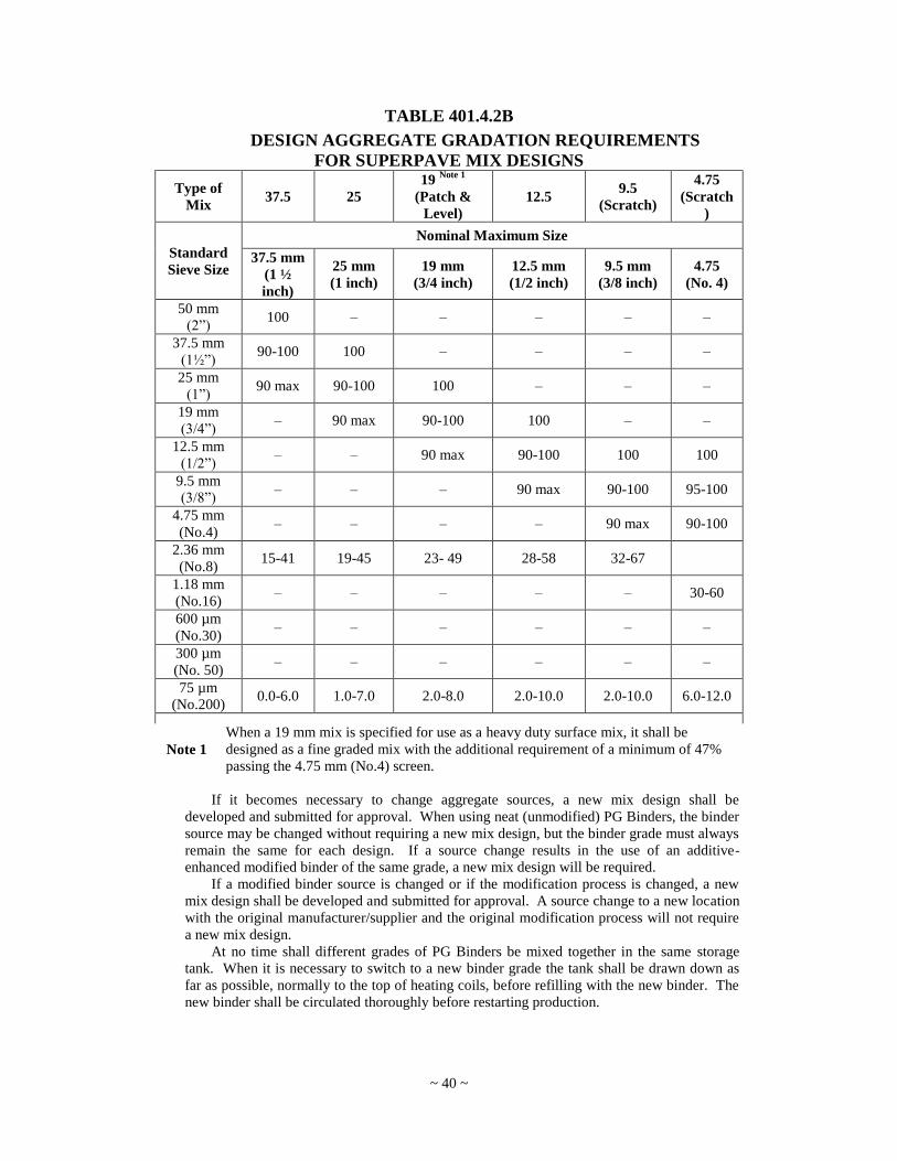
~ 40 ~
TABLE 401.4.2B
DESIGN AGGREGATE GRADATION REQUIREMENTS
FOR SUPERPAVE MIX DESIGNS
Type of
Mix 37.5 25
19 Note 1
(Patch &
Level)
12.5 9.5
(Scratch)
4.75
(Scratch
)
Standard
Sieve Size
Nominal Maximum Size
37.5 mm
(1 ½
inch)
25 mm
(1 inch)
19 mm
(3/4 inch)
12.5 mm
(1/2 inch)
9.5 mm
(3/8 inch)
4.75
(No. 4)
50 mm
(2”) 100 – – – – –
37.5 mm
(1½”) 90-100 100 – – – –
25 mm
(1”) 90 max 90-100 100 – – –
19 mm
(3/4”) – 90 max 90-100 100 – –
12.5 mm
(1/2”) – – 90 max 90-100 100 100
9.5 mm
(3/8”) – – – 90 max 90-100 95-100
4.75 mm
(No.4) – – – – 90 max 90-100
2.36 mm
(No.8) 15-41 19-45 23- 49 28-58 32-67
1.18 mm
(No.16) – – – – – 30-60
600 µm
(No.30) – – – – – –
300 µm
(No. 50) – – – – – –
75 µm
(No.200) 0.0-6.0 1.0-7.0 2.0-8.0 2.0-10.0 2.0-10.0 6.0-12.0
Note 1
When a 19 mm mix is specified for use as a heavy duty surface mix, it shall be
designed as a fine graded mix with the additional requirement of a minimum of 47%
passing the 4.75 mm (No.4) screen.
If it becomes necessary to change aggregate sources, a new mix design shall be
developed and submitted for approval. When using neat (unmodified) PG Binders, the binder
source may be changed without requiring a new mix design, but the binder grade must always
remain the same for each design. If a source change results in the use of an additive-
enhanced modified binder of the same grade, a new mix design will be required.
If a modified binder source is changed or if the modification process is changed, a new
mix design shall be developed and submitted for approval. A source change to a new location
with the original manufacturer/supplier and the original modification process will not require
a new mix design.
At no time shall different grades of PG Binders be mixed together in the same storage
tank. When it is necessary to switch to a new binder grade the tank shall be drawn down as
far as possible, normally to the top of heating coils, before refilling with the new binder. The
new binder shall be circulated thoroughly before restarting production.
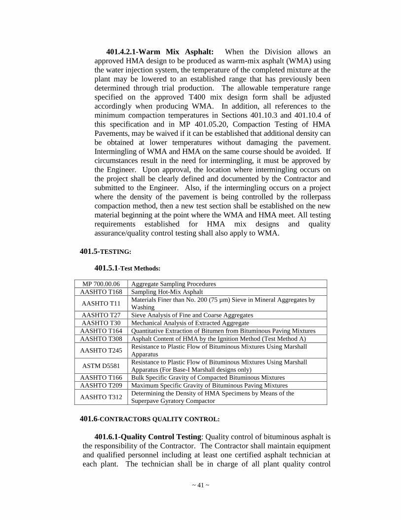
~ 41 ~
401.4.2.1-Warm Mix Asphalt: When the Division allows an
approved HMA design to be produced as warm-mix asphalt (WMA) using
the water injection system, the temperature of the completed mixture at the
plant may be lowered to an established range that has previously been
determined through trial production. The allowable temperature range
specified on the approved T400 mix design form shall be adjusted
accordingly when producing WMA. In addition, all references to the
minimum compaction temperatures in Sections 401.10.3 and 401.10.4 of
this specification and in MP 401.05.20, Compaction Testing of HMA
Pavements, may be waived if it can be established that additional density can
be obtained at lower temperatures without damaging the pavement.
Intermingling of WMA and HMA on the same course should be avoided. If
circumstances result in the need for intermingling, it must be approved by
the Engineer. Upon approval, the location where intermingling occurs on
the project shall be clearly defined and documented by the Contractor and
submitted to the Engineer. Also, if the intermingling occurs on a project
where the density of the pavement is being controlled by the rollerpass
compaction method, then a new test section shall be established on the new
material beginning at the point where the WMA and HMA meet. All testing
requirements established for HMA mix designs and quality
assurance/quality control testing shall also apply to WMA.
401.5-TESTING:
401.5.1-Test Methods:
MP 700.00.06 Aggregate Sampling Procedures
AASHTO T168 Sampling Hot-Mix Asphalt
AASHTO T11 Materials Finer than No. 200 (75 µm) Sieve in Mineral Aggregates by
Washing
AASHTO T27 Sieve Analysis of Fine and Coarse Aggregates
AASHTO T30 Mechanical Analysis of Extracted Aggregate
AASHTO T164 Quantitative Extraction of Bitumen from Bituminous Paving Mixtures
AASHTO T308 Asphalt Content of HMA by the Ignition Method (Test Method A)
AASHTO T245 Resistance to Plastic Flow of Bituminous Mixtures Using Marshall
Apparatus
ASTM D5581 Resistance to Plastic Flow of Bituminous Mixtures Using Marshall
Apparatus (For Base-I Marshall designs only)
AASHTO T166 Bulk Specific Gravity of Compacted Bituminous Mixtures
AASHTO T209 Maximum Specific Gravity of Bituminous Paving Mixtures
AASHTO T312 Determining the Density of HMA Specimens by Means of the
Superpave Gyratory Compactor
401.6-CONTRACTORS QUALITY CONTROL:
401.6.1-Quality Control Testing: Quality control of bituminous asphalt is
the responsibility of the Contractor. The Contractor shall maintain equipment
and qualified personnel including at least one certified asphalt technician at
each plant. The technician shall be in charge of all plant quality control

~ 42 ~
activities such as mix proportioning and adjustment and all sampling and
testing activities necessary to maintain the various properties of asphalt within
the limits of the specification. A certified asphalt inspector may handle
sampling and testing activities under the supervision of the plant technician.
The Contractor shall maintain equipment and qualified personnel
including at least one certified Compaction Technician at each project. A
certified Compaction Technician shall perform all testing necessary to assure
compaction of the asphalt meets specification requirements. The Contractor,
or Contractor-Producer, shall design a workable Quality Control Plan,
detailing the type and frequency of sampling and testing deemed necessary to
measure and control the magnitude of the various properties of the asphalt
governed by these specifications. This plan, prepared in accordance with MP
401.03.50 shall be submitted to the Engineer for review prior to production of
material under this specification.
401.6.2-Job Mix Formula (JMF) Field Verification: For each JMF, a
mix design field verification shall be conducted during the first days of plant
production. For Marshall designs, the verification shall be in accordance with
the guidelines established in MP 401.02.27. For Superpave, designs it shall be
in accordance with MP 401.02.29. The field verification is for the purpose of
demonstrating that the JMF can be produced within the specified tolerances
set forth in the MP. If the mix cannot be produce within these requirements, a
new mix design will be required.
401.6.3-Quality Control Testing Requirements: After the JMF design
field verification has been successfully completed, sampling frequency and
test requirements for quality control shall be as set forth in MP 401.02.27 for
Marshall designs and MP 401.02.29 for Superpave designs. If the Division
determines that a mix cannot be consistently produced within the tolerance
limits of the specified design properties, approval of the mix may be revoked
and the contractor will be required to provide a new mix design.
401.7-ACCEPTANCE TESTING:
401.7.1-Acceptance Testing of HMA: Acceptance testing of asphalt is
the responsibility of the Division. For Superpave mixes, the acceptance
sampling and testing requirements for the mixture shall be as set forth in MP
401.02.29.
401.7.2-Surface Tolerance: It is the intent of these specifications that
projects with a total new pavement thickness of 3 inches (75 mm) or more and
minimum length of two lots (1100 ft. (340 m)) shall be constructed to provide
a smooth riding surface. The smoothness of the riding surface will be
determined by the Engineer using an inertial profilometer or Mays Ride
Meter. The smoothness testing will generally be accomplished within 30 days
after the project is complete. On urban projects with numerous side streets
where traffic must cross through the paving operation, the Engineer shall
determine if it is practical to evaluate the pavement for smoothness.

~ 43 ~
The pavement will be divided into sampling LOTS of one-tenth (0.1) lane-
mile (0.16 km) each. Each LOT shall exhibit a smoothness measurement,
expressed in inches per mile (millimeters per kilometer) equal to or less than
that shown in the appropriate Table 401.7.2E or 401.7.2M. When a LOT is
represented by a smoothness number greater than that shown in Tables
401.7.2E or 401.7.2M, the unit price shall be adjusted as in 401.13.2.
TABLE 401.7.2E
Total New Pavement Thickness Smoothness
3 inches to 4 inches 81 inches per mile or less
4 inches or greater 65 inches per mile or less
TABLE 401.7.2M
Total New Pavement Thickness Smoothness
75 mm to 100 mm 1 250 mm/km or less
100 mm or greater 1 000 mm/km or less
When compaction is completed on the course, it shall present a uniform
surface, true line and grade, conforming to the cross section shown on the
Plans. When tested with a straightedge of approximately 10 feet (3 meters) in
length and a template of the specified dimensions, the finished base course
shall not show a deviation greater than ¼ inch (6 mm) and the finished
wearing course shall not show a deviation from the required surface greater
than 3/16 inch (5 mm).
The Contractor shall provide the straightedge and template for checking
the surfaces and an employee to use them under the direction of the Engineer.
Any irregularity of the surface exceeding the limits specified shall be
corrected. Depressions which develop after the initial rolling shall be
corrected by loosening the mixture and adding new material. High places
shall be corrected by removing excess material.
Areas of completed courses found to be defective shall be removed and
replaced with approved mixtures laid in accordance with these specifications,
and no additional compensation will be allowed for materials used or work
involved in replacing defective areas.
401.7.3-Compaction: Acceptance testing for compaction shall be
performed in accordance with either the Lot-by-Lot method described in
Section 401.7.3.1 or the rollerpass procedure described in MP 401.05.20,
based the following criteria:

~ 44 ~
Roadway Type Compaction Method
Interstate and Expressways Lot By Lot
APD Routes Lot By Lot
NHS Routes Lot By Lot
All other routes and roadways Determined by Table 401.7.3.A
Patching-and-leveling and scratch courses shall not be included in
determining the total new pavement thickness. When asphalt is placed in areas
that require a non-uniform thickness or is tapered to a thin edge, the method of
acceptance testing shall be determined by the Engineer. Acceptance testing is
not required on areas in which a full-size roller is restricted from properly
compacting the mat. These areas shall be compacted to the satisfaction of the
Engineer.
Table 401.7.3A
Mainline Compaction Methods
Traffic
Type
Total
New
Pavement
Thickness
Marshall
Lift Thickness
Superpave
Lift Thickness
Compaction
Method Notes -1, 2
Heavy
≥ 3
million
ESALs
≥ 2.5
inches
(63 mm)
≥ 1.5 inch (37.5
mm)
≥ 1.5 inch
(37.5 mm) Lot-by-Lot
< 1.5 inch (37.5
mm)
< 1.5 inch
(37.5 mm) Rollerpass
< 2.5
inches (63
mm)
> 1.5 inch (37.5
mm)
> 1.5 inch
(37.5 mm) Lot-by-Lot
≤ 1.5 inch (37.5
mm)
≤ 1.5 inch
(37.5 mm) Rollerpass
Medium
< 3
million
ESALs
≥ 3.0
inches
(75 mm)
> 1.5 inch (37.5
mm)
> 1.5 inch
(37.5 mm) Lot-by-Lot
≤ 1.5 inch (37.5
mm)
≤ 1.5 inch
(37.5 mm) Rollerpass
< 3.0
inches (75
mm)
All lifts All lifts Rollerpass
Note 1 Any lift that is placed at a thickness of less than two times the
nominal maximum aggregate size, as specified in either Table
401.4.2A or Table 401.4.2B, shall be compacted using the rollerpass
method.
Note 2 Any asphalt that has been specified with a higher than standard grade
PG Binder (i.e. PG 70-22, PG 76-22, etc.) shall be compacted using
the Lot by Lot method in accordance with Section 10.0 of MP
401.05.20.
~ 45 ~
Table 401.7.3B
Other Compaction Situations
Procedure Construction
Situation Compaction Method
Shoulders New Construction Lot-by-Lot
Overlay Projects Rollerpass
Shoulders With Rolled-
In Rumble Strips Surface Course Only See Section 401.7.3.2
Trench Paving All Rollerpass or Satisfaction
of the Engineer
Pavement Widening All Rollerpass or Satisfaction
of the Engineer
Pavement Repairs All Rollerpass or Satisfaction
of the Engineer
401.7.3.1-LOT-By-LOT Testing: Randomly located nuclear
density tests will be performed in accordance with the LOT-By-LOT test
procedure described in MP 401.05.20. The pavement shall be divided into
LOTS not exceeding 1000 feet (300 meters) of paving lane. A randomly
located density test shall be conducted in each LOT. The density shall be
within the range of 92 to 96% of the maximum density of the approved
mix design or the maximum density established under Section 401.6.2,
Job Mix Formula Verification. If the density is outside the range, an
additional five tests shall be conducted for the LOT and the average of
these five tests used to judge acceptance of the LOT in accordance with
Table 401.13.3.
401.7.3.2-Shoulders With Rolled-In Rumble Strips: On both
new construction and overlay projects, the compaction requirement for the
surface course of the shoulder shall be in accordance with the rollerpass
procedure described in MP 401.05.20. However, the number of roller passes
may be reduced in the area of the rolled-in rumble strip to allow for the
proper placement of the rumble strip.
401.7.4-Thickness: When a uniform thickness of three inches (75
mm) or more is specified, excluding resurfacing, cores shall be taken to
verify the thickness of the compacted pavement.
Cores will be taken by the Division at random locations. The
sampling frequency shall be approximately five cores per 2,000 feet (600
meters) of two-lane construction, except that the sampling frequency shall
normally be limited to a minimum of five and a maximum of 50 cores per
project. The Division may elect to waive coring for short projects of less
than 1,000 feet (300 meters) in length or for projects where a paving mat
of uniform thickness cannot be expected (for example: tapered paving

~ 46 ~
mats or pavement widening projects). The Division may also elect to take
additional cores when needed to resolve problems related to pavement
thickness.
The thickness shall be considered acceptable if one or both of the
following criteria are met:
(a) The average thickness equals or exceeds the specified thickness.
(b) The average thickness is less than the specified thickness, but the
difference is not statistically significant at the 95% confidence
level. (Standard one tail “t” test at 0.05 significance).
The calculated „t‟ value shall be less than or equal to the standard „t‟ value
at the 95% confidence level. The method for calculating Criteria „B‟, shall
be as follows:
t t 95 Where:
t 95 = value from standard “t” table for 95% confidence level.
tx x
sn
s
1
xs = specified thickness
_
x = average thickness
n = number of samples
s
xx
n
n
2
2
1
( )
x = individual core thickness
If the average thickness is less than specified and is determined to be
significant as determined by criteria „B‟, the Division shall decide on a
course of action as described in Section 401.13.4.
401.8-WEATHER RESTRICTIONS: Bituminous asphalt shall only be placed when the surface is dry and when
weather conditions are such that proper handling, finishing, and compaction can
be accomplished. In no case however, shall asphalt be placed when the surface
temperature is below the minimum established in Table 401.8.

~ 47 ~
TABLE 401.8
Course Thickness Minimum Surface Temperature
3 inches (75 mm) and over 35 °F (2 °C) Note -1
1.5 to 2.9 inches (38 to 74
mm) 40 °F (4 °C)
Less than 1.5 inches (38 mm) 50 °F (10 °C)
Note 1 In lieu of 35 °F (2 °C), a minimum air temperature of 40 °F (4 °C)
shall be used when paving directly on an aggregate base, subbase,
or subgrade
In addition to the above surface temperature requirements, no wearing
courses shall be placed when the air temperature is less than 40° F (4° C).
401.8.1-Cold Weather Paving: When the air temperature falls below 50°
F (10° C) or the surface temperature falls below 60° F (15° C) the provisions
for cold weather paving shall apply.
Paving shall be performed so that the transverse joints in adjacent lanes
shall be no more than 50 feet (15 meters) apart at the end of each day's paving
operations.
The surface temperature shall be taken a minimum of once every hour and
shall be taken in all shaded areas. The temperature requirements as listed in
Table 401.8 shall apply.
It shall be the Contractor's responsibility to monitor the declining surface
temperature to insure that material delivery from the plant be terminated so as
to allow that all material can be placed prior to the surface temperature falling
below the surface temperatures listed in Table 401.8.
The temperature of the delivered material and the mat temperature at the
time final density is obtained shall be taken for every truck load. These
temperatures shall be in accordance with Section 401.10.3 for delivered
material and 401.10.4 for the mat temperature at the time final density is
obtained.
401.9-EQUIPMENT:
401.9.1-Plants: All plants in West Virginia producing asphalt for the
Division shall provide documented evidence of compliance with current
requirements of the West Virginia Air Pollution Control Commission.
All plants which are not in West Virginia but producing asphalt for the
West Virginia Division of Highways shall provide documented evidence of
compliance with current requirements of the laws and regulations of the State
in which they are producing, applicable to air pollution. All plants shall meet
the general requirements set forth in AASHTO M156 unless it can be
demonstrated to the satisfaction of the Engineer that a consistent quality mix
can be produced with modifications to any of these requirements.
~ 48 ~
401.9.2-Dust Collector: An efficient dust collecting system shall be
provided to prevent the loss of fine material. The material collected may be
returned to the mixture at a uniform rate or discarded.
401.9.3-Truck Scales: Truck scales shall be provided at each Plant,
except that truck scales are not required at properly calibrated automatic
batching plant facilities which are equipped with digital printout equipment,
and which load the trucks directly from the mixer or the weigh hopper in a
surge or storage bin.
A person designated as a weigher shall be provided by the producer. The
weigher shall certify that the weight of the asphalt, as determined either by the
truck scales or from the digital printout of the batch weights, is correct.
Each truck shall be weighed empty prior to each load, except at automatic
batch plants approved to operate without truck scales.
All truck scales shall be mounted on solid foundations which will insure
them remaining plumb and level.
Approval and sealing of scales shall be conducted at the frequency
determined by the West Virginia Division of Labor, Bureau of Weights and
Measures, and when the plant is moved, or upon the request of the Engineer.
The Engineer shall be notified of any scale malfunctions when material is
being furnished to Division of Highways projects. The Division may, at its
option, accept inspection and sealing by out-of-state agencies when the
mixing plant is located outside West Virginia.
A digital recorder shall be required on all truck scales. The digital
recorder shall produce a printed record of the gross, tare and net weights, and
the time, date, truck identification, and project number. Provision shall be
made for constant zero compensation and further provision shall be made so
that the scales may not be manually manipulated during the printing process.
The system shall be interlocked so as to allow printing only when the scale
has come to rest. In case of breakdown of the automatic equipment, the
Engineer may permit manual operation for a reasonable time, normally not to
exceed 48 hours, while the equipment is being repaired.
The scales shall be of sufficient size and capacity to weigh the loaded
trucks that are used for delivery of asphalt from the plant.
401.9.4-Test Weights: As part of its standard equipment, each plant
which proportions aggregate by weight shall provide a minimum of ten 50-
pound (22.68 kg) test weights for the purpose of maintaining the continued
accuracy of its weighing equipment.
Plants which proportion asphalt material by weight shall furnish, in
addition to the above, one five pound (2.268 kg) test weight.
401.9.5-Surge and Storage Bins: During the normal daily operation of
the plant, asphalt may be stored in a surge or storage bin for a maximum of 12
hours, provided the bin has received prior evaluation and acceptance through
the District plant inspection. The resulting temperature of the material at time
~ 49 ~
of placement and compaction shall be sufficient to comply with 401.10.3 and
401.10.4
Longer silo storage times, up to 24 hours, may be permitted for dense
graded asphalt if the storage silo is insulated and/or heated to assure that the
proper mix temperature is maintained. The gates at the bottom of the storage
silo shall be adequately heated and sealed when the asphalt is held for the
extended period of time. An inert gas system may be used to purge the silo of
oxygen to prevent oxidation of the asphalt. The asphalt delivered from the
storage silo shall meet all of the specification requirements.
When asphalt is stored for the extended time period, it shall not be used
until the temperature has been checked and the asphalt has been visually
inspected for hardening of the mix and stripping of the asphalt from the
aggregate. Approval of the extended storage time may be revoked if it is
determined through inspection and/or testing that the extended storage is
having a detrimental effect on the asphalt.
Loading of trucks through the storage bin will only be permitted when a
minimum 25-ton (23-Mg) buffer of material is being maintained or an amount
as recommended by the bin manufacturer, means shall be provided for loading
the trucks directly from the mixer when the storage bin is not in operation.
401.9.6-Inspection of Equipment and Plant Operations: The Engineer
shall have access to the plant to assure the adequacy of the equipment in use,
to inspect the conditions and operation of the plant, to verify weights, to verify
the proportion and character of materials, and to determine if specified
temperatures are being maintained in the preparation of the mixture.
401.9.7-Trucks for Transporting Mixture: The inside surfaces of trucks
shall be thinly coated with a soapy water or a mixture with not more than ten
percent lubricating oil. The use of diesel fuel, kerosene, or similar solvent-
based products which can dissolve the asphalt film from the aggregate
particles will not be permitted. Any commercial release agent which can be
certified as harmless to the mix may be used; however, the Division reserves
the right to restrict any release agent that is shown to cause problems during
placement of the mix. In the case of mixtures composed of PG Binders which
contain polymer modification, truck surfaces should be coated with a release
agent recommended by the binder supplier. All excess coating material shall
be removed from the truck bed prior to loading the asphalt.
All truck beds shall be insulated with approved material. No trucks shall
be used which cause segregation of the materials, which show large oil leaks,
or which cause undue delays in delivery of material. All trucks shall be
provided with a waterproof cover and a hole in the body for the purpose of
conveniently checking the temperature of the load. Covers shall be suspended
slightly above the mixture, shall extend over the sides of the truck, and shall
be securely fastened to eliminate air infiltration and to prevent water from
coming in contact with the mixture.
~ 50 ~
401.9.8-Laboratory: A testing facility or laboratory, as described below,
shall be provided within reasonable proximity of the asphalt plant. Plant
operations must be visible from within the laboratory.
The laboratory shall be of sufficient size to hold all laboratory test
equipment and supplies with adequate floor space to allow the technicians to
test samples in an efficient manner. The laboratory shall be furnished and
maintained with adequate ventilation, heat, light, water, sink and drainage,
electrical or gas outlets, or both, work table, shelves, and supply cabinets.
The laboratory shall be supplied with the equipment and materials listed
below and these shall be maintained to meet the applicable requirements of
AASHTO or ASTM:
i. Hot plate, gas or electric.
ii. Large ovens (as needed for heating and drying samples), gas or electric.
iii. Unit weight container, ½ cubic foot (0.014 cubic meter). Required for
slag only.
iv. Balances of sufficient capacity and accuracy for conducting specified
tests and plant calibration.
v. Thermometers: dial type, liquid-in-glass, and digital as required for
conducting standard test procedures and monitoring mix temperatures.
Digital thermometers shall be equipped with an appropriate sturdy probe
that can be pushed into a sample of hot asphalt to check the temperature
of the mix.
vi. Standard Gilson shaker or equivalent, with screens.
vii. Ro-Tap shaker or equivalent, with 8 and/or 12 inch (200 and/or 300
mm) diameter screens.
viii. Sample splitters for fine and coarse aggregates.
ix. Miscellaneous items (including sample splitting trowels, scoops, square
point shovel, aggregate sample pans, heat resistant gloves, measuring
rules, brushes, flashlight, timing devices, and glassware as needed).
x. Expendable supplies necessary for performance of tests.
xi Equipment for determining the maximum specific gravity of asphalt
mixtures as specified in AASHTO T209.
xii. Equipment for determining the in-place density of asphalt mixtures
meeting the requirements of MP 401.05.20.
xiii. Non-contact infrared thermometer accurate to ± 2° F (± 1° C).
xiv. Equipment for determining the bulk specific gravity of HMA using
saturated surface dry specimens complying with AASHTO T166.
xv. Marshall equipment necessary to comply with AASHTO T245 and
ASTM D5581, including a calibrated automatic testing apparatus having
recording capabilities and compaction hammers. (Marshall designs
only)
xvi. Asphalt content ignition oven with built-in scale and printer meeting the
requirements of AASHTO T308, Test Method A. (Optional for Marshall
designs – Mandatory for Superpave designs)

~ 51 ~
xvii. Calibrated Gyratory compactor meeting requirement of AASHTO T312
with computer (including software for data acquisition and test
calculations) and primer. Compactor must be calibrated to the internal
angle in accordance with AASHTO TP71 with annual verification
(Superpave designs only).
401.9.9-Asphalt Paving Equipment: Asphalt paving equipment shall be
self-contained and of sufficient size, power and stability to receive, distribute
and strike-off the asphalt mixture at rates and widths commensurate with the
typical sections and other details shown on the plans. The paver shall be
provided with an activated screed or strike-off assembly equipped to be
heated. Approval of the paver by the Engineer will be based on the
demonstrated capability of the equipment to place the mixture to the required
cross-section, profile and alignment in an acceptable, finished condition ready
for compaction.
The paver shall be equipped with means of preventing the segregation of
the coarse aggregate particles when moving the mixture from the paver
hopper to the paver augers. It shall also be capable of pushing a sufficient
amount of the mixture under the auger gearbox to prevent streaking or tearing
of the mat. Some paver models may require the installation of a manufacturer
retrofit kit or equipment modification to accomplish this.
Specialized equipment or hand methods approved by the Engineer may be
employed to spread the asphalt mixture where the use of standard full scale
paver is impractical due to the size or irregularity of the area to be paved.
Pavers shall be equipped with mechanical or automatic grade and slope
controls. The use of automatic grade and slope controls with a traveling
straight edge shall be required only when specified on the Plans or in the
Proposal. Both the grade and slope controls shall be in working order at all
times. In the event of failure of the automatic controls, the Contractor will be
permitted to finish the day's work using manual controls but will not be
allowed to resume work the following day until the grade and slope controls
are in proper working order.
401.9.10-Compaction Equipment: Compaction may be performed by
self-propelled steel-wheeled, pneumatic-tired and/or vibratory rollers. Hand-
held rollers or vibrating plates may be used in small inaccessible areas if
approved by the Engineer. Prior to use on any project, the roller shall be
inspected to see that it is in good mechanical condition. The total weight,
weight per inch of width (steel-wheeled), and average ground contact pressure
(pneumatic-tired) shall be documented.
401.10-PAVING OPERATIONS:
401.10.1-Cleaning and Sweeping: Immediately prior to the arrival of the
paving mixture, the existing base or surface shall be thoroughly cleaned by the
use of tools and equipment as may be required to remove all mud, dirt, dust,

~ 52 ~
and other caked or loose material foreign to the type of treatment or surface
being placed. The cleaning shall be done to a minimum width of one foot on
each side beyond the width of the surface being placed.
401.10.2-Patching and Leveling and Scratch Courses:
401.10.2.1-Patching and Leveling: A tack coat shall be applied to the
existing pavement prior to placing patching and leveling.
Patching and leveling shall be placed at various locations throughout
the project to remove irregularities in the existing pavement such as dips,
or to raise the outside edge of the existing pavement to provide a uniform
template prior to placing a base or wearing course. Patching and leveling
shall not be placed as a continuous layer or course over the full width and
length of the project.
Compaction of patching and leveling shall be performed with three-
wheel (steel) or pneumatic-tire rollers.
401.10.2.2-Scratch Course: A tack coat shall be applied to the
existing pavement prior to placing a scratch course.
The scratch course shall be placed to the limits designated on the
plans. Scratch course shall be placed with a paving machine. The paving
machine screed shall be set to drag on the high areas of the existing
pavement, only depositing material in ruts and other depressions.
The wearing course, or at least one lift of base course, should be
placed over the scratch course prior to maintaining traffic in the lane
where the scratch course has been placed. All repairs to a scratch course
due to traffic damage shall be at the contractor‟s expense.
Compaction of a scratch course shall be performed with a three-
wheel (steel) or pneumatic-tire roller.
401.10.3-Spreading and Finishing: Before spreading any material, the
contact surfaces of curbs, gutters, manholes, and of adjacent Portland cement
concrete pavement edges shall be painted or sealed with asphalt material.
Exact edge of pavement, except on concrete, shall be established by a string or
chalk line for a distance of not less than 500 feet ahead of the spreading
operation.
For mixes produced with neat (non-modified) asphalts (which may include
PG 70-22, PG 64-22, PG 64-28, and PG 58-28) the temperature of the mixture
at the time of placement shall be within the temperature requirements of the
JMF. The JMF temperature range shall be within the master temperature
range of 250° and 338° F (121° and 170° C) unless otherwise specified by the
asphalt supplier. The mix temperature shall be monitored by inserting a dial
type thermometer into the mix through the hole in the truck bed.
The temperature of the completed mix, when measured at the plant, shall
be within the tolerance as established by the JMF. The first load which
demonstrates temperatures outside of that range shall be accepted, provided

~ 53 ~
that the temperature is still within the master temperature range. No
additional loads of material shall be run out until necessary steps are taken to
reestablish the temperature of the mix within the plant tolerance. When
measured at the project site, the temperature of the mix shall be within the
tolerance established by the JMF. The first truck load of material which
demonstrates temperatures outside of that range or any trucks in transit at that
time shall be accepted provided temperatures are within the master
temperature range. Any truckload of material which exceeds the master
temperature range may be rejected by the Engineer. However, the plant shall
immediately be notified that no additional loads of material are to be
dispatched until necessary action is taken to reestablish temperature within
JMF specification limits.
When the surface temperature falls to within 10° F (6° C) of the weather
restrictions of Table 401.8, the mix temperature may be increased up to a
maximum of 338° F (170° C) unless otherwise specified by the asphalt
supplier. The temperature of each truckload of material shall be monitored for
compliance. Any truckload of material which exceeds this maximum
temperature may be rejected by the Engineer.
Mixes produced with asphalts that contain modifiers for high or low
temperature performance enhancement shall meet the temperature
requirements recommended by the asphalt supplier, which will be referenced
on the JMF.
401.10.4-Rolling Procedure: Shoulders, ramps, and similar areas shall
be compacted in the same method as the mainline.
During rolling, roller wheels shall be kept moist with only enough water to
avoid picking up material. Fuel oil on roller wheels or pneumatic tires is not
allowed. Rollers shall move at a slow but uniform speed with the drive roll or
wheels nearest the paver.
If rolling causes material displacement, the affected area shall be loosened
at once with lutes or rakes and restored to its original grade with loose
material before being re-rolled. Heavy equipment, including rollers, should
not be permitted to stand on the finished surface before it has thoroughly
cooled or set.
Mat temperature shall be measured using a non-contact infrared
thermometer. The required density shall be obtained prior to the mat
temperature reaching 175° F (80° C). The Contractor shall be allowed to
lower this temperature to 165° F (74° C) if they can demonstrate during the
first day of placement of each lift on each project that additional densification
can be achieved without causing any pavement distress.
401.10.5-Joints: The longitudinal joint in any layer shall offset that in the
layer immediately below by approximately six inches; however, the joint in
the top layer shall be at the centerline of the pavement if the roadway
comprises two lanes of the width, or at lane lines if the roadway is more than
~ 54 ~
two lanes in width. The transverse joint in any layer shall offset that in the
layer immediately below by approximately six feet.
All transverse joints between existing and new pavement shall be “heeled-
in” to the existing surface at the beginning and at the end of the project and at
all other locations where the new pavement terminates against an existing
pavement. Transverse joints between one day's production and the next shall
be carefully constructed and shall be formed by cutting back into the existing
section to expose the full depth of the course. All joints shall be squared up to
the full vertical depth of the course to be placed, and a tack coat of asphalt
material shall be applied. Joints adjacent to curbs, gutters, or adjoining
pavement shall be formed by transporting back sufficient hot material to fill
any space left uncovered by the paver.
The longitudinal joint between adjacent mats shall be set up to a sufficient
height to receive the full compactive effort from the rollers and shall be tacked
prior to placing adjacent material.
Transverse joints shall be checked for smoothness with a ten foot straight
edge provided by the Contractor. All surface irregularities shall be corrected
prior to proceeding with paving operations.
401.11-PROTECTION OF PAVEMENT AND TRAFFIC CONTROL:
The Contractor shall be responsible for the protection of asphalt surfaces
from damage by their equipment and personnel. When the construction of asphalt
surfaces is undertaken on projects under public traffic and the road surface is 16
feet wide or greater and the ADT is 400 or greater, the Contractor shall place no
passing signs, Interim pavement markings, and Temporary pavement markings to
delineate the edge line, centerline, and/or lane line of the roadway as required
herein and in the project plans.
Interim markings are described as markings applied to freshly resurfaced
roadways between lifts and after placement of the final lift prior to opening the
portion of the roadway being resurfaced to traffic. These markings are intended
to provide the minimum amount of delineation required for safe navigation of the
roadway, and are to be succeeded by. Temporary markings within a three (3) to
fourteen (14) day period, based on the type of roadway and AADT, as specified
herein.
Temporary markings are described as markings, typically short-lived in
nature, which supplant Interim markings and are to be succeeded by Permanent
markings within a sixty (60) day time period.
Permanent markings are described as the final pavement marking
application within a project. These markings generally supplant Temporary
markings. There shall be a minimum calendar day time period, as defined in
Section 663, provided between the placement of Temporary and Permanent
pavement markings, depending on the seasonal time of placement .
The Contractor shall be responsible for maintaining both signs and
Temporary pavement markings until such time as the Permanent markings are
placed, or thirty calendar days after completion of the final course, whichever is

~ 55 ~
less. No separate payment will be made for maintenance of these items but shall
be included in the applicable pay items for initial installation.
Interim pavement markings shall be Type VIIA Interim Pavement
Markings applied as described in Section 663.5.6 and shall meet the requirements
of Material Section 715.40.3. Temporary pavement markings shall be as
described in Section 636.8 and shall meet the requirements of the applicable
Materials Section. Permanent markings shall be as described in Section 663.5.2
and shall meet the requirements of the applicable Materials Section. All Interim,
Temporary, and Permanent Pavement Markings shall be in conformance with the
Manual on Uniform Traffic Control Devices (MUTCD).
All Interim pavement markings shall be installed by the end of the work
day by placing the markings as the paving operation progresses within 1000 feet
(300 meters) of the paver. Removal of Interim pavement markings shall not be
required between lifts or after placement of the final markings. Payment of
Interim pavement markings shall be incidental to the 401 Items.
401.11.1-Interim Traffic Control for Two-Lane, Two-Way Roadways:
Prior to any work which will cover the centerline, the Contractor shall install
24-inch x 30-inch “DO NOT PASS” (R4-1) signs on permanent posts at the
beginning of each no passing zone throughout the length of the project. These
signs shall be placed at the beginning of each no passing zone and shall be
repeated every 2,500 feet as required. Payment shall be made under the
“Traffic Control Devices” item.
To delineate the centerline of the roadway, the Contractor shall install
yellow Interim Pavement Markings measuring 4 inches x 4 inches along the
centerline of the roadway on 20 foot centers.
401.11.1.1-Temporary Pavement Markings for two-way, two-lane
roadways
401.11.1.1.1-AADT equal to or > 3,000: The Interim Pavement
Markings described in 401.11.1 shall be permitted only for a period of up
to three (3) calendar days after completion of the final course. Within this
time, the Contractor shall install a full compliance Temporary centerline
and full compliance Temporary edgelines in conformance with Section
636. Payment for Temporary pavement markings shall be made under the
“Temporary Pavement Marking Paint” pay item.
401.11.1.1.2-AADT < 3,000: The Interim Pavement Markings
described in 401.11.1 shall be permitted only for a period of up to fourteen
(14) calendar days after completion of the final course. Within this time,
the Contractor shall install a full compliance Temporary centerline and full
compliance Temporary edgelines in conformance with Section 636.
Payment for Temporary pavement markings shall be made under the
“Temporary Pavement Marking Paint” pay item.

~ 56 ~
401.11.2-Interim Traffic Control for One-Way Multilane Roadways:
On all one-way multilane roadways, the Contractor shall install white Interim
Pavement Markings measuring 4 inches x 48 inches along the lane line.
Interim Pavement Markings shall be placed on 40-foot centers.
401.11.2.1-Temporary Pavement Markings: After paving is first
completed in the left lane, and prior to the left lane being opened to traffic,
the Contractor shall install a full compliance Temporary yellow edge line.
Prior to the remaining lanes being opened to traffic, the Contractor shall
install a full compliance Temporary white lane lines and white edge line.
These markings shall be in conformance with Section 636. Payment for
Temporary pavement markings shall be made under the “Temporary
Pavement Marking Paint” pay item.
401.11.3-Interim Traffic Control for Two-Way Three-Lane
Roadways: Prior to any work which will cover the centerline and/or lane
lines, the Contractor shall install 24-inch x 30-inch “DO NOT PASS” (R4-1)
signs on permanent posts at the beginning of each no-passing zone throughout
the length of the project as required. “DO NOT PASS” signs in both
directions will be required for Center Left Turn Lanes.
These signs shall be placed at the beginning of each no-passing zone and
shall be repeated every 2500 feet as required. Payment shall be made under
the “Traffic Control Devices” item.
The Contractor shall install Interim Pavement Markings measuring 4
inches x 48 inches. Where truck-climbing lanes exist, the centerline shall be
marked with two parallel yellow lines separated by a four-inch space placed
on 40-foot centers. Lane lines shall be marked with white lines placed on 40-
foot centers. Where center left-turn lanes exist, the center lane shall be
marked with two parallel yellow lines separated by a four-inch space, and
placed on 40-foot centers on both sides of the center lane.
401.11.3.1-Temporary Pavement Markings: The Interim Pavement
Markings described in Section 401.11.3 shall be permitted only for a
period of up to three calendar days after completion of the final course.
Within this time, the Contractor shall install full compliance centerline,
lane line, and edgeline Temporary pavement markings in conformance
with Section 636. Payment for Temporary pavement markings shall be
made under the “Temporary Pavement Marking Paint” pay item.
401.11.4-Interim Traffic Control for Two-Way Four-Lane and Five-
Lane Roadways: On all two-way four-lane and five-lane highways, the
Contractor shall install Interim Pavement Markings measuring 4 inch x 48
inch along the lane line and centerline where required. Centerlines shall be
marked with two parallel yellow lines separated by a four inch space placed
on 40 foot centers. On five-lane roadways these markings shall be placed on

~ 57 ~
both sides of the center left turn lane. Lane lines shall be marked with white
lines placed at 40 foot centers.
401.11.4.1-Temporary Pavement Markings: The Interim Pavement
Markings described in Section 401.11.4 shall be permitted only for a
period of up to three calendar days after completion of the final course.
Within this time the Contractor shall install full compliance Temporary
lane line, centerline, and edge line pavement markings in conformance
with
Section 636. Payment for Temporary pavement markings shall be
made under the “Temporary Pavement Marking Paint” pay item.
401.11.5-Seasonal Temporary Markings: If it becomes necessary to
open the roadway to traffic prior to the completion of paving operations for
longer than 14 calendar days, whether on the base or final course, the
Contractor shall install full compliance Temporary pavement markings in
conformance with Section 636. Payment for Temporary pavement markings
shall be made under the “Temporary Pavement Marking Paint” pay item.
401.12-METHOD OF MEASUREMENT: Asphalt concrete will be measured by the ton (Mg), or square yard
(square meter). For projects paid by the ton, the quantity will be
determined by the Contractor from the total weigh slips for each vehicle
load weighed upon an approved standard scale or from digital printout slips
from an automatic batching plant, and certified by the Contractor as
correct. For projects paid by the square yard, the quantity will be determined
by the Plan Quantity as provided for in the proposal unless otherwise directed
by the Engineer.
Any patching or leveling mixture placed on a subbase or base
course constructed in the same Contract with the asphalt items shall be at
the expense of the Contractor. No additional compensation will be allowed
for the material or any work incidental to its placement.
401.13-BASIS OF PAYMENT: The quantities determine as provided above, will be paid for at the
contract unit price for the items listed below, which prices and payment shall be
full compensation for furnishing all the materials and doing all the work herein
prescribed in a workmanlike and acceptable manner, including all labor, tools,
equipment, field laboratory, supplies, and incidentals necessary to complete the
work.
The conditioning, cleaning, and sweeping of the existing base or
underlying surface shall be considered as part of the construction of the
appropriate items listed in 401.14, and no additional compensation will be
allowed for "Cleaning and Sweeping".

~ 58 ~
There will be no additional compensation for tack coat material used for
minor (spot) areas to be patched and leveled; the cost of this tack coat material
will be included in the unit bid price for the “patching and leveling” Item.
There will be no additional compensation for Interim Pavement Markings.
401.13.1-When a LOT of Superpave asphalt material is found not in
compliance with the tolerance requirements of MP 401.02.29, it shall be
subject to a price adjustment in accordance with the criteria established in this
MP.
401.13.2 – When a LOT of asphalt pavement is represented by a
smoothness value larger than that shown in Tables 401.7.2E or 401.7.2M, the
unit price of the LOT (surface course only) shall be determined as follows:
ENGLISH VERSION: Reduced Unit Price = Unit Bid Price X [(127.86 – As)/100]
Where A = 0.429 when specified smoothness is 65 in/mi
Where A = 0.341 when specified smoothness is 81 in/mi
Where s = Smoothness value measured as per 401.7.2
METRIC VERSION: Reduced Unit Price = Unit Bid Price X [(127 – As)/100]
Where A = 0.0274 when specified smoothness is 1 000mm/km
Where A = 0.0218 when specified smoothness is 1 250 mm/km
Where s = smoothness value measured as per 401.7.2
When the measured smoothness value exceeds the specified value by 50%
or more, the LOT so measured shall be corrected, at the Contractor‟s expense,
to comply with Tables 401.7.2E or Table 401.7.2M.
401.13.3- When a LOT of asphalt pavement does not meet the density
requirements of 401.7.3, the Price shall be adjusted as follows:
Formula-1: Projects requiring only mat density testing :
Lot Price Adjustment (Mat only) = (unit price) X (Lot quantity) X (
mat density price adjustment %
from Table 401.13.3A)

~ 59 ~
TABLE 401.13.3A
ADJUSTMENT OF CONTRACT PRICE
FOR PAVEMENT DENSITY NOT WITHIN
TOLERANCE OF DENSITY
Percent of Density Percent of Contract
Price to be Paid
Greater than 96 % Note 2
95% to 96% 102 92% to 94%
92 % to 94 % 100
91% 98 90% 96
89% 92 88% 88
Less than 88% Note 2
Note 1 Mat density slightly above 96% is normally only a problem if it leads to
asphalt flushing on the surface of the mat or rutting due to an unstable
mix. The Division will make a special evaluation of the material and
determine the appropriate action
Note 2 When the density is less than 92%, the mat will be more susceptible to
accelerated deterioration and a decrease in the expected service life of
the pavement. For price adjustments on mat densities less than 88%, the
percent of Contract Bid Price will be decreased by 10% per percentage
of mat density less than 88%, unless a Special evaluation performed by
the Division determines a more appropriate action.
401.13.4-When a LOT of asphalt pavement is determined to be
statistically non-conforming in accordance with criteria „B‟ of Section
401.7.4, the Division will review the plans and project records to determine if
there is an acceptable explanation for this deficiency. If it is determined that a
deficiency does exist, one of the following adjustments may be used. If the
deficiency is less than ¾ inch (19 mm), the Division may choose to accept the
material at a price equal to the bid price times the ratio of the average
thickness divided by the specified thickness. If the deficiency is ¾ inch (19
mm) or greater, the Division may require that an additional lift of material
[specified to the nearest ¼ inch (6 mm) of the deficiency] be placed at the
Contractor‟s expense. Retesting of the overlay will be at the expense of the
Contractor in accordance with MP 109.00.20.

~ 60 ~
401.14-PAY ITEMS:
Item
Number
Description Unit
401001-* “design method” ASPHALT BASE COURSE,
“aggregate type”, TYPE “mix type”** Ton (Mg)
401002-* “design method” ASPHALT WEARING
COURSE, “aggregate type”, TYPE “mix type”** Ton (Mg)
401003-* “design method” ASPHALT PATCHING AND
LEVELING COURSE, “aggregate type** Ton (Mg)
401007-* “design method” SCRATCH COURSE,
“aggregate type” , TYPE „mixed type”** Ton (Mg)
* “design method” shall be either Marshall or Superpave
* “aggregate type” shall be either stone and gravel or slag
* “mix type” from Table 401.4.2A or 401.4.2B
* Sequence Number
** Type Of Aggregate
SECTION 402
HOT-MIX ASPHALT BASE, WEARING, AND PATCHING
AND LEVELING COURSES
DELETE HEADING AND CONTENTS AND REPLACE WITH THE FOLLOWING
SECTION 402
BITUMINOUS ASPHALT SKID RESISTANT PAVEMENT
402.1-DESCRIPTION: This work shall consist of constructing a Hot-Mix Asphalt (HMA) and
Warm-Mix (WMA) Skid Resistant Wearing Coarse or a Superpave (HMA or
WMA) Skid Resistant Wearing Coarse in accordance with the requirements of the
Section 401 Asphalt Specification with the following exceptions and additions:
402.2-MATERIALS:
The coarse aggregate shall consist of gravel, slag, or other acceptable
polish resistant aggregate, or combinations thereof, meeting the requirement of
Subsections 703.1 through 703.3, except as amended in this subsection.
When stone or gravel is specified in the contract, the coarse aggregate
shall consist of gravel or other acceptable polish resistant aggregate, or
combination thereof meeting the requirements of 703.1 through 703.3, except as
amended in this subsection. When slag is specified in the contract, the coarse
aggregate shall be slag which meets the requirements of 703.3, except as amended
in this subsection.

~ 61 ~
Acceptable dolomite may be used alone or as a part of a coarse aggregate
blend on roadways with a projected ESAL value of less than 3,000,000. On
roadways with a projected ESAL value of 3,000,000 or greater, acceptable
dolomite may be used only as a part of the coarse aggregate blend and shall not
exceed 50% of that blend.
The total of shale (determined by MP 703.00.27), coal and other
lightweight deleterious material (determined by ASTM C123) and friable
particles (determined by MP 703.01.20) shall not exceed three percent.
402.2.1-Marshall Mix Designs: For Marshall mix designs, the coarse
aggregate or blends thereof shall have a minimum of 80 percent two-face
fracture, and, except for those carbonate rocks which may be designated as
acceptable polish resistant aggregate, the portion obtained on the No. 4 (4.75
mm) sieve shall contain no more than 15 percent carbonate particles.
The total thin and elongated pieces, when tested as per MP 703.00.25,
shall not exceed five percent.
402.2.2-Superpave Mix Designs: For Superpave mix designs, the
coarse aggregate or blends thereof shall have a minimum angularity
requirement as specified in MP 401.02.28, Table 401.02.28C and, except
for those carbonate rocks which may be designated as acceptable polish
resistant aggregate, the portion obtained on the No. 4 (4.75 mm) sieve
shall contain no more than 15 percent carbonate particles.
Flat and elongated particles shall be tested in accordance with ASTM
D4791 and the procedure modification referenced in AASHTO MP2. The
total flat and elongated particles, measured at a 5:1 ratio, shall not exceed
ten percent by weight for all pavements where the estimated traffic level is
greater than or equal to 0.3 million ESALs.
402.3-FINE AGGREGATE:
402.3.1-Marshall Mix Designs: Fine aggregate shall meet the
requirements of 702.3.
402.3.2-Superpave Mix Designs: Fine aggregate shall meet the
requirements of 702.3 along with the addition of the fine aggregate angularity
and sand equivalent requirements noted in MP 401.02.28, Table 401.02.28C.
402.4-MIXING:
The skid resistant paving mix shall be type designated on the plans.
402.5-PAY ITEMS:
Method of measurement and basis of payment will be in accordance with
the applicable sections of Section 401.

~ 62 ~
ITEM DESCRIPTION UNIT
402001-* Marshall Asphalt Skid Resistant Pavement,
“aggregate type”, TYPE “mix type”
TN (MG)
402001-* Superpave Asphalt Skid Resistant Pavement,
“aggregate type”, TYPE “mix type”
TN (MG)
“design method” shall be either Marshall or Superpave
“aggregate type” shall be either stone and gravel or slag
“mix type” from Table 401.4.2A or 401.4.2B
Sequence number
SECTION 408
TACK COAT
408.9-JOINTS:
DELETE THE CONTENTS OF THE SECTION AND REPLACE WITH
THE FOLLOWING:
Longitudinal joints shall be treated using an application rate that will
thoroughly coat the vertical face without excessive runoff
.

~ 63 ~
DIVISION 500
RIGID PAVEMENT
SECTION 501
UNBONDED CONCRETE OVERLAY
DELETE THE TITLE OF THE SECTION AND RENAME AS THE
FOLLOWING:
SECTION 501
PORTLAND CEMENT CONCRETE PAVEMENT
501.1-DESCRIPTION:
DELETE THE FIRST PARAGRAPH OF THE SUBSECTION AND
REPLACE WITH THE FOLLOWING:
This work shall consist of a pavement or an unbonded overlay pavement
composed of portland cement concrete, with or without reinforcement as shown
on the Plans, constructed on a prepared subgrade, base course, or existing
pavement in accordance with these Specifications and in reasonably close
conformity with the lines, grades, thicknesses, and typical cross sections shown
on the Plans or established by the Engineer.
501.4-TESTING:
501.4.4.-Testing for Opening Pavement to Traffic:
INSERT THE FOLLOWING AFTER THE FIRST PARAGRAPH AS
PARAGRAPH TWO:
In lieu of the cylinders outlined in the previous paragraph, the Contractor
may use the Maturity Method for the estimation of concrete strength, as
outlined in MP 601.04.21, for determining when the pavement may be opened
to traffic.
501.4.5-Compressive Strength Tests for Acceptance:
ADD THE FOLLOWING PARAGRAPH AT THE END OF THE
SUBSECTION:
Compressive strength of concrete overlays less than 8 inches (200 mm) in
thickness shall be determined in accordance with Section 601.4.4, with one set
of test specimens representing a maximum of 500 yd3 (380 m
3) of concrete.
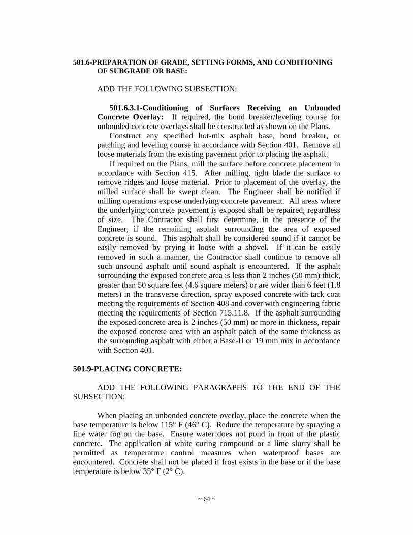
~ 64 ~
501.6-PREPARATION OF GRADE, SETTING FORMS, AND CONDITIONING
OF SUBGRADE OR BASE:
ADD THE FOLLOWING SUBSECTION:
501.6.3.1-Conditioning of Surfaces Receiving an Unbonded
Concrete Overlay: If required, the bond breaker/leveling course for
unbonded concrete overlays shall be constructed as shown on the Plans.
Construct any specified hot-mix asphalt base, bond breaker, or
patching and leveling course in accordance with Section 401. Remove all
loose materials from the existing pavement prior to placing the asphalt.
If required on the Plans, mill the surface before concrete placement in
accordance with Section 415. After milling, tight blade the surface to
remove ridges and loose material. Prior to placement of the overlay, the
milled surface shall be swept clean. The Engineer shall be notified if
milling operations expose underlying concrete pavement. All areas where
the underlying concrete pavement is exposed shall be repaired, regardless
of size. The Contractor shall first determine, in the presence of the
Engineer, if the remaining asphalt surrounding the area of exposed
concrete is sound. This asphalt shall be considered sound if it cannot be
easily removed by prying it loose with a shovel. If it can be easily
removed in such a manner, the Contractor shall continue to remove all
such unsound asphalt until sound asphalt is encountered. If the asphalt
surrounding the exposed concrete area is less than 2 inches (50 mm) thick,
greater than 50 square feet (4.6 square meters) or are wider than 6 feet (1.8
meters) in the transverse direction, spray exposed concrete with tack coat
meeting the requirements of Section 408 and cover with engineering fabric
meeting the requirements of Section 715.11.8. If the asphalt surrounding
the exposed concrete area is 2 inches (50 mm) or more in thickness, repair
the exposed concrete area with an asphalt patch of the same thickness as
the surrounding asphalt with either a Base-II or 19 mm mix in accordance
with Section 401.
501.9-PLACING CONCRETE:
ADD THE FOLLOWING PARAGRAPHS TO THE END OF THE
SUBSECTION:
When placing an unbonded concrete overlay, place the concrete when the
base temperature is below 115° F (46° C). Reduce the temperature by spraying a
fine water fog on the base. Ensure water does not pond in front of the plastic
concrete. The application of white curing compound or a lime slurry shall be
permitted as temperature control measures when waterproof bases are
encountered. Concrete shall not be placed if frost exists in the base or if the base
temperature is below 35° F (2° C).

~ 65 ~
When placing unbonded concrete overlays, concrete should be placed on
the grade to the nominal thickness shown on the Plans. Any deviations for profile
adjustments, and/or cross section adjustments, should be above the nominal
thickness. When adjustments are necessary for grade or yield improvement, the
thickness shall not, in any case, be less than the minimum thickness shown on the
Plans.
501.11-JOINTS:
DELETE THE ENTIRE SECTION AND ADD THE FOLLOWING:
Joints shall be constructed of the type and dimensions and at the locations
shown on the approved Joint Layout Plan(s). The Contractor shall submit for
approval a Joint Layout Plan for all intersections on the project in general
accordance with the following: “Street Jointing Criteria: Ten Rules Of Practice”
as suggested by the Portland Cement Association (PCA), Skokie, Illinois; the
American Concrete Pavement Association‟s Intersection Joint Layout Guidelines;
the West Virginia Division Of Highways‟ Standard Specifications, dated 2010
and the latest issue of any subsequent Supplemental Specifications; the West
Virginia Division Of Highways‟ “Standard Details Book Volume 1 – Drainage,
Guardrail, Pavement, Fence, and Markers” hereinafter referred to as “Standard
Details Volume 1”; or as directed by the Engineer.
The “Street Jointing Criteria: Ten Rules of Practice” suggested by the
PCA are paraphrased and revised for the West Virginia Division of Highways‟
needs as follows:
i. Joints are used in concrete pavement to aid construction and to
minimize random cracking. Avoid odd-shaped areas of pavement.
ii. Space longitudinal joints not to exceed 12.0 ft. (3.8 m). The
contractor shall decide on the type of longitudinal joint as shown
on Standard Detail Sheet PVT1 of “Standard Details Volume 1”
needed depending on the type of construction. Type D joints will
be used for full-width construction. Type D joins with a projecting
tie bar for the following lane/shoulder pour are acceptable. Type E
joints without the key are acceptable for lane-at-a-time
construction. Type F joints are not acceptable at any location on
the project.
iii. Space transverse joints at regular intervals of 15.0 ft. (4.6 m) or
less.
iv. Thinner slabs tend to crack at closer intervals than do thicker slabs.
Long narrow slabs tend to crack more than square ones.
v. All contraction and expansion joints must be continuous through
any Combination Concrete Curb and Gutter or Integral Concrete
Curb (Standard Sheet PVT6, Sheet 1 of 2 of Standard Details
Volume 1). See Standard Specification Section 610.3.4.

~ 66 ~
vi. Longitudinal construction joints should be butt-type joints with
tiebars (Types D or E joints based on construction method) as
shown on Standard Detail Sheet PVT1 of Standard Details Volume
1. The purpose of these tiebars is to hold adjacent slabs in vertical
alignment. The normal backfill behind any integral curb or curb
and gutter constrains the slabs and holds them together. With
separate curb and gutter built on fill, use Type E Joints as shown
on Standard Detail Sheet PVT1 of Standard Details Volume 1.
vii. Offsets at radius points should be at least 2.0 ft. (0.60 m) in width.
Angles of less than 60º shall be avoided.
viii. Make minor adjustments in joint locations to meet all structures
projecting through, into or against the pavement. Minor
adjustments should not make any joint spacing greater than that
specified in ii. and iii. in this list.
ix. (Deleted)
x. Manhole and inlet frames, as well as any other metal structure
projecting through, into or against the pavement shall be isolated in
accordance with 501.11.6.
The Contractor shall submit a Joint Layout Plan for each intersection on
the Project to the Engineer for approval a minimum of 10 working days before
ordering materials. No work on or ordering of materials for the intersections shall
be performed until the Engineer has approved the Joint Layout Plan(s). These
Submittals are not required to be signed and sealed by a Registered Professional
Engineer.
501.11.1-Longitudinal Joints: Deformed steel tie bars (Type D joint) or
tie bolt assemblies (Type E joint) shall be placed perpendicular to the
longitudinal joints. They shall be placed by suitable mechanical equipment or
rigidly secured by suitable supports to prevent displacement. Tie bars shall be
epoxy coated and free of grease, oils, dirt, paint or other foreign materials, and
shall not be enclosed in tubes or sleeves.
All longitudinal joints shall be sawed normal to the surface of the
pavement with a suitable concrete saw. Construction of longitudinal joints
shall be in accordance with the appropriate requirements, as follows:
i. When the longitudinal joint separates adjacent pavement lanes or
slabs that are poured at the same time (full-width construction:
Type D joint), sawing of longitudinal joints shall be performed
between 4 and 24 hours after the pavement is placed and before
any equipment and vehicles are allowed on the pavement. The saw
cut shall be to a minimum depth of one-third of the plan depth of
pavement; the width shall be 1/8 in. (3 mm), with a tolerance of
plus or minus 1/16 in. (2 mm).
ii. When the longitudinal joint separates adjacent pavement lanes or
slabs that are poured separately (lane-at-a-time construction: Type

~ 67 ~
D or E joint), the longitudinal joint shall be sawed. The saw cut
shall be to a depth of 1 in. (25 mm), plus ¼ in. (6 mm); the width
shall be 1/8 in. (3 mm) plus or minus 1/16 in. (2 mm).
501.11.2-Transverse Expansion Joints (Type B or Type C joint): The
expansion joint filler shall be one piece, continuous from form to form, shaped
to the subgrade and to the cross section of concrete. The filler shall be
depressed ½ in. (13 mm) below the surface of the pavement.
The expansion joint filler shall be held in a vertical position. Finished
joints shall not deviate more than ¼ in. (6 mm) in the horizontal alignment
from a straight line at right angles to the centerline of the pavement. No plugs
of concrete will be permitted anywhere within the expansion space.
501.11.3-Transverse Contraction Joints: Transverse contraction (Type
A) joints shall consist of planes of weakness created by sawing or forming
grooves, normal to the grade, in the surface of the pavement as shown on the
approved Joint Layout Plan(s). These contraction joint grooves shall be
centered, within 1 in. (25 mm) of the mid-length of the dowels, over the
coated dowel bars specified.
Unless otherwise specified or authorized, all transverse contraction joint
grooves shall be constructed as described, resulting in the dimensions detailed
on the approved Joint Layout Plan(s) and at the spacing and locations shown
on the Plans.
As soon as feasible after placing the concrete, the contraction joints shall
be sawed to the dimensions shown on the approved Joint Layout Plan(s).
Sawing of joints shall commence as soon as the concrete has hardened
sufficiently to permit sawing without excess raveling, usually 4 to 24 hours.
All joints shall be sawed before uncontrolled shrinkage cracking takes place,
but no later than 24 hours after placement of concrete. If necessary, sawing
operations shall be continuous, through day and night, regardless of weather
conditions. In general, all joints should be sawed in sequence. The sawing of
any joint shall be omitted if cracking occurs at or near the joint location prior
to the time of sawing. Sawing of a joint shall be discontinued when a crack
develops ahead of the saw. If extreme conditions exist which make it
impractical to prevent erratic cracking by early sawing, the contraction joints
shall be formed in the plastic concrete.
All joint repair work shall be done at the Contractor's expense and to the
satisfaction of the Engineer.
When formed joints are permitted, they shall be effected by an approved
mechanically operated device to the dimensions specified and while the
concrete is still in the plastic state.
Random cracking at transverse contraction joints, as described in
501.11.7, shall be sealed with silicone sealant.
501.11.4-Transverse Construction Joints: Transverse construction
joints shall be installed when there is an interruption of more than 30 minutes

~ 68 ~
in the concreting operations. No construction joint shall be installed within 10
ft. (3 meters) of an expansion or contraction joint. If sufficient concrete has
not been placed to form a slab at least 10 ft. (3 meters) long, the excess
concrete back to the last proceeding joint shall be removed.
Construction joints shall be constructed in a manner similar to transverse
contraction joints utilizing a Type A joint. The groove shall have the same
dimensions as for transverse contraction joints.
501.11.5-Coated Dowel Bars: Coated dowel bars (load transfer
reinforcement) shall be used across all transverse Type A joints as shown on
the approved Joint Layout Plan(s). Dowels shall be located at mid-depth of
the pavement with a tolerance of placement within plus or minus 1 in. (25
mm) of the lateral and vertical positions shown on the approved Joint Layout
Plan(s). Dowels shall be aligned parallel to the centerline and surface of the
pavement with a tolerance for such alignments within plus or minus 0.6 inches
(15 mm) per dowel.
Dowels shall be held in position in the pavement by means of metal
supports that remain in the pavement, except as noted. The combination of
dowel bars and all the various components of the metal supports at a joint is
commonly referred to as the dowel bar assembly or load transfer unit.
Welding of dowels to the supports, to achieve a fixed end condition, shall be
performed in accordance with the details shown on the approved Joint Layout
Plan(s). For dowel assemblies at contraction and construction joints, welding
of dowels to any member of the supports will not be permitted within the
middle one-third of the dowel‟s length. The longitudinal misalignment of one
end of a dowel assembly with respect to the other end in achieving a
perpendicular alignment with the centerline of the pavement (longitudinal side
shift) shall not exceed 2 inches (50 mm) when 18 inch (450 mm) long dowel
bars are used. Acceptance of a type of dowel assembly by the Division in no
way relieves the Contractor of their responsibility for furnishing, as part of the
assembly, coated dowel bars that meet the requirements of 709.15, nor does it
relieve the Contractor of the Contractor‟s responsibility for placing and
maintaining the assembly in its proper position and alignment during paving
operations.
The mechanical implanting method of placing dowel bars is permitted if
the Contractor can show, by the method outlined below or other approved
methods, that the dowel bars can be placed within the required tolerance with
no adverse effects to the finished concrete pavement. Prior to, or on the first
day of the paving operation, the Contractor shall use non-destructive testing
methods, such as the MIT Scan-2 technique, approved by the Engineer, to
confirm dowel placement and alignment.
Dowel bars shall be placed to within plus or minus 1 inch (25 mm) of the
depth shown on the plans, and parallel to the traffic lane centerline and top of
roadway surface within a tolerance of 0.6 inches (15 mm) per 18 inches (450
mm) of dowel bar length.
~ 69 ~
Suspend paving operations if dowels are installed improperly and dowel
alignment does not meet the specified tolerances. Paving operations shall not
be resumed until the Contractor demonstrates to the Engineer that the problem
has been corrected.
For coated dowel bar types that require a bond breaker, the bond breaking
material, prequalified for use with that particular type coating, shall be
carefully applied over the entire length of the bar just prior to placement of
concrete unless an approved bondbreaker lubricant has been applied in the
shop.
The free end of expansion joint dowels utilized in a Type B joint shall be
provided with a close fitting metal cap or sleeve equipped with a stop to
prevent closing during paving operations. A clearance of 1 in. (25 mm) shall
be maintained between the closed end of the cap and the end of the dowel to
accommodate future movement of the concrete slab.
501.11.6-Expansion Joints Around Structures: Expansion joints shall
be formed by placing pre-molded expansion joint material about all structures
and features projecting through, into or against the pavement. Unless
otherwise indicated, such joints shall be ½ in. (13 mm) in width.
501.11.7-Random Cracks: Random cracks falling within 3 inches (75
mm) of the center of the transverse contraction joint's dowel bars shall be
sawed for the full width, widening and deepening the crack to the dimensions
of sawing for transverse contraction joints.
If any random or uncontrolled crack occurs outside 3 inches (75 mm) from
a doweled joint, the entire pavement within the lane where such crack occurs
shall be removed for the entire 15ft panel between joints.. The dowel
assembly or bars, as the case may be, shall be replaced with a new dowel
assembly with drilling. The new joint over the dowel assembly shall be
initially formed by the use of a removable insert or by sawing. The tie bars
shall be replaced with a Modified Type E joint. The above described work
shall be done at no additional cost to the Division.
501.11.9-Transverse Joints in Concrete Shoulders: Dowel bars are not
required in paved shoulders except where turning traffic may use the
shoulders as a lane.
501.14-CURING:
501.14.4-White Pigmented Impervious Membrane:
ADD THE FOLLOWING PARAGRAPH AFTER THE SECOND
PARAGRAPH:
For unbonded concrete overlays, the curing compound application rates
noted below shall be doubled.

~ 70 ~
501.16-SEALING JOINTS:
Cleaning and sealing of all joints is not required unless shown in the Plans.
501.16.1-Silicone Sealant:
DELETE THE FIFTH PARAGRAPH AND REPLACE WITH THE
FOLLOWING:
Immediately following placement of the sealant and before a skin forms,
the sealant shall be tooled to force it against the joint faces and to provide a
slightly concave surface with a depth of approximately ¼ inch (6 mm) (at the
center of the joint) below the pavement surface.
501.22-METHOD OF MEASUREMENT:
ADD THE FOLLOWING PARAGRAPHS AFTER THE FIRST
PARAGRAPH:
When Item 501009-* is specified in the project plans, the quantity of
concrete overlay placement to be paid for will be the number of square yards
(meters) complete in place and accepted. The width for measurement will be the
width of the pavement or overlay shown on the typical cross section of the Plans
and additional widening where called for or as otherwise directed in writing by
the Engineer. The length will be measured on the surface along the centerline of
each roadway and each roadway ramp.
When Item 501011-* is specified in the project plans the quantity of
concrete used in concrete overlays to be paid for will be the number of cubic
yards (meters) in place and accepted. The Engineer will measure the volume of
concrete used in concrete overlays using the Contractor‟s certified batch tickets or
other approved documentation.
501.23-BASIS OF PAYMENT:
501.23.1-General:
DELETE THE SECTION AND REPLACE WITH THE FOLLOWING:
501.23.1-General: The quantities, determined as provided above, will be
paid for at the contract unit prices less adjustments referred to below, which
shall constitute full compensation for furnishing and preparing of all
materials, including reinforcing steel, transverse and longitudinal joints,
expansion joint filler, elastomeric joint seals, silicone sealant, epoxy mortar
for joint repair work, polyethylene tape, rope or rod joint back-up material,
lubricant-adhesive for elastomeric seals, and dowels or load transfer devices

~ 71 ~
as are required in the Plans; construction of any bond breaker/leveling course,
milling existing surface; placing, finishing and curing concrete; and all labor,
equipment, tools, field laboratory, supplies and incidentals necessary to
complete the work.
501.24-PAY ITEMS:
ADD THE FOLLOWING PAY ITEMS:
ITEM DESCRIPTION UNIT
501009-* “Thickness” UNBONDED PORTLAND
CEMENT CONCRETE OVERLAY
Square Yard
(Meter)
501011-* UNBONDED PORTLAND CEMENT
CONCRETE OVERLAY
Cubic Yard
(Meter)
* Sequence number
SECTION 503
SEALING CRACKS IN CONCRETE PAVEMENT
DELETE THE SECTION AND REPLACE WITH THE FOLLOWING:
503.1-DESCRIPTION:
This work shall consist of the cleaning and sealing of cracks in concrete
pavement in the manner and subject to the conditions and regulation prescribed.
503.2-MATERIALS:
The sealant shall be in accordance with section 708.3.
The joint back-up material shall be in accordance with section 708.4.2,
shall meet the requirements of the Sealant Manufacturer, and shall be appropriate
for outdoor applications.
503.3-CONSTRUCTION METHODS:
Old filler and foreign material in the cracks shall be removed. The cracks
shall then be sealed as prescribed. Other means and/or methods recommended by
the Sealant Manufacturer and approved by the Engineer may be used.
503.4-PREPARATION OF MATERIAL BEFORE USE:
Before charging the compound into the melting unit, the unit shall be free
from all foreign material. If the type of heater to be used requires that the sealing
material as shipped, be cut into smaller pieces before melting, the method used is
subject to approval by the Engineer.
The heating kettle used for melting sealing materials shall be of the
indirect heating or double boiler type, using oil as the heat transfer medium. It
shall have a thermostatically controlled heat source, a built-in automatic agitator,

~ 72 ~
and thermometers installed to indicate both the temperature of the melted sealing
material and that of the oil bath. Other methods of indirect heating approved by
the Engineer may be used. A positive means of controlling the temperature of the
heat transfer medium at all points in the system shall be incorporated in the
heater. Sealing material shall be uniformly heated until the pouring temperature
recommended by the Sealant Manufacturer is reached. Should the maximum
recommended pouring temperature be exceeded, the material will be rejected.
The material shall be poured as soon as possible after the pouring temperature is
reached. Only sufficient material for the day‟s operation shall be heated each day.
Other means and/or methods recommended by the Sealant Manufacturer and
approved by the Engineer may be used.
503.5-PREPARATION OF JOINTS FOR SEALING:
Cracks should be widened with a crack saw to a minimum width of ½” (16
mm) and to a depth necessary to provide a 1:1 width to depth ratio including room
for the backer rod. The cracks shall be thoroughly cleaned of all loose scale, dirt,
dust, other foreign matter, old sealant and loosely stuck particles of mortar and
aggregate, so that dry, sound, and clean surfaces result. The use of any tool which
results in damage to the pavement is prohibited. Just prior to the actual sealing
operation, the crack shall be thoroughly blown out with an air jet having sufficient
volume and pressure to remove any loose material left by the cleaning operation.
After the final cleaning, the back-up material shall be inserted into the crack in
accordance with the Manufacturer‟s recommendations to provide the correct
shape factor for the sealant.
503.6-EQUIPMENT FOR APPLYING SEALER:
The equipment used for the placing of sealing material in the cracks may
consist of conventional hand pouring pots, individual mechanical pouring kettles
mounted on wheels with a pouring shoe, or heating units from which material
may be discharged into the joint through the use of flexible lines and suitable
shoes. Any heat, which it may be necessary to apply to sealing material after it
leaves the main heating unit, shall be applied by indirect and controlled methods
as specified in 503.4. No direct heat will be permitted on the pouring unit in order
to meet field controls set forth below. Any method of placing sealing material,
which results in compliance with the following requirements, will be satisfactory.
503.7-PLACEMENT REQUIREMENTS:
After insertion of the back-up material and prior to becoming
contaminated, the crack shall be sealed in accordance with the Sealant
Manufacturer‟s recommendations. At the time of sealing, the crack faces shall be
dry and dust free. The sealant shall be introduced into the crack in a continuous
uniform operation to properly fill and seal the crack from the bottom upward in
order to avoid trapping any air bubbles. The crack shall be sealed to within 1/8 to
¼ inch (3 to 6 mm) below the pavement surface. Traffic shall not be allowed on
the sealed joint for the minimum time recommended by the Sealant Manufacturer
after placement, unless otherwise approved by the Engineer.

~ 73 ~
Sealant shall never be applied to frozen, dirty, wet, or damp concrete or
during inclement weather conditions. Sealant shall not be placed in the cracks
unless the temperature of the pavement is 40° F (4° C) or higher unless approved
by the Engineer.
503.8-METHOD OF MEASUREMENT:
The quantity of work done will be measured in linear feet (meters) of
“Sealing Cracks”, when the item below is included in the contract.
503.9-BASIS OF PAYMENT:
The quantity of work, as described above, will be paid for at the contract
unit price bid for the item below, which price and payment shall be full
compensation for furnishing all the materials and doing all the work prescribed in
an acceptable manner, including all the labor, tools, equipment, supplies, and
incidental items necessary to complete the work.
503.10-PAY ITEM:
ITEM DESCRIPTION UNIT
503001-
* Sealing Cracks in Concrete Pavement
Linear Foot
(Meter)
* Sequence number
SECTION 506
CONCRETE PAVEMENT REPAIR
DELETE ENTIRE SECTION AND REPLACE WITH THE
FOLLOWING:
506.1-DESCRIPTION: This work consists of the removal and replacement of deteriorated
concrete pavement and patches, and replacing subbase material where required, at
locations as shown on plans or as specified by the Engineer.
The following is a description of each patch type:
i. Jointed Concrete Pavement Patch, Type I:
Patching shall consist of full depth, full lane width concrete pavement
repairs equal to or greater than 6 feet (1.8 meters) in length. Type I
patches shall constructed in accordance with the Concrete Repair
Details in the plans.
ii. Jointed Concrete Pavement Patch, Type II:
Patching shall consist of partial depth concrete pavement repairs that
extend a minimum of 2 inches (50mm) and no deeper than one-half the

~ 74 ~
slab thickness at cracks or no more than one-third the slab thickness at
doweled joints. Type II patches shall be constructed in accordance
with the Concrete Repair Details in the plans.
iii. Jointed Concrete Pavement Patch, Type III:
Patching shall consist of a repair along the edge of a transverse crack
or joint that extends from the bottom of a partial depth repair (Type II)
to potentially the full depth of the slab, and isolated within 12” of
either the longitudinal joint or pavement edge. Type III patches shall
be constructed in accordance with the Concrete Repair Details in the
plans.
506.2-MATERIALS: Materials shall meet the requirements of section 501 or 601, and as
follows:
MATERIAL SECTION OR
SUBSECTION
Subbase 307
Portland Cement Concrete 501 or 601
Epoxy-Coated Dowel Bars 709.15
Tie Bars and Hook Bolts 709.1
Joint Sealer 708.3, 708.4
Accelerating Admixtures 707.13
Curing Materials 707.6-707.10
An approved epoxy grout shall be used to firmly anchor dowel bars in 30
minutes.
Cement meeting the requirements of ASTM C150, Type III may be used
in the concrete mixes for concrete pavement repair.
506.3-PROPORTIONING: Portland cement concrete for patching concrete pavement shall meet the
requirements of Section 501 or Class B concrete as specified in Section 601,
except that it shall be shown by compressive strength tests that the concrete mix
shall attain 2,000 psi (13.8 Mpa) prior to the time at which the pavement will be
opened to traffic, and an AASHTO number 8 coarse aggregate for use in Type II
repairs with a depth of 3 inches (75mm) or less.
Type III repairs may be placed simultaneously with Type II repairs. When
constructed in this manner, the same concrete mix shall be used in both repair
types.

~ 75 ~
Prior to the start of work, the Contractor shall submit the mix proportions
and recent compressive strength test data for the specified age at which the
concrete is to be opened to traffic.
506.4-TESTING: All testing shall be in accordance with section 501. The Contractor shall
fabricate a minimum of nine compressive strength cylinders for each 24 hour
period of operation. Six of these nine field cured cylinders shall be field cured in
a temperature and moisture condition as close as possible to that of the concrete in
the repair area. When the average strength of three of these cylinders, representing
the concrete placed, indicate that the concrete has attained the required strength
for opening to traffic, that concrete may be put into service. These cylinders shall
represent concrete produced from the batch from which they were fabricated and,
if applicable, concrete from previous batches also. These cylinders will not
represent any concrete which was placed after the time that they were fabricated.
Three of the nine cylinders shall receive standard curing and shall be tested at
28days to verify that the required strength at that age has been achieved.
In lieu of six field cured cylinders required above, the Contractor may use
the Maturity Method for the Estimation of concrete strength, as outlined in MP
601.04.21 for determining when the pavement may be opened to traffic.
506.5-EQUIPMENT AND TOOLS:
Equipment and tools shall be in accordance with section 501 unless noted
otherwise. Saw cutting equipment shall be capable of sawing neat vertical faces
along the patch boundaries. The use of a carbide-toothed wheel saw shall not be
permitted for sawing the patch boundaries. A carbide-tipped wheel saw may be
used for additional saw cuts provided that a minimum 3-inch (75 mm) clearance
from the sawed boundary is maintained.
506.6-CONSTRUCTION METHODS:
506.6.1-Removal of Existing Pavement: Designated defective pavement
shall be removed full depth, and undisturbed portions of the existing pavement
adjacent to the area to be patched shall be left with straight vertical sides.
The existing pavement to be removed shall be sawed full depth along the
transverse and longitudinal boundaries, including the lane and shoulder/lane
joints as shown on the plans or as directed by the Engineer. Additional saw
cuts inside the patch boundaries will be permitted to facilitate the concrete
removal operation.
Concrete sawn full depth to be removed shall be lifted out by means of
chains, lift-pins, or other approved devices. The breaking of concrete in-place
shall not be permitted. During the removal operations, utmost care shall be
exercised to minimize disturbance and damage to the base material, and the
adjacent pavement and shoulder.

~ 76 ~
506.6.2-Conditioning Existing Subbase: Prior to placing concrete in the
repair area, any subbase material that is disturbed below the desired level of
cleanout shall be removed and the patch area compacted to the satisfaction of
the Engineer. Unsuitable subbase material, concrete, reinforcing steel, and
any other debris shall become property of the Contractor and shall be legally
disposed. The Contractor shall replace the removed subbase material with
concrete integral to pavement replacement up to a maximum 1-inch (25 mm)
depth. In the event that soft areas are encountered in the subbase or subgrade,
or if more than 1-inch (25 mm) of subbase material is removed, replacement
of subbase and subgrade shall be in accordance with section 307, testing shall
be waived. When subbase or subgrade material is replaced, it shall be brought
to grade and compacted to the satisfaction of the Engineer.
506.6.3-Placing Concrete: Unless behind permanent closures or unless
otherwise approved by the Engineer, all excavated areas shall be patched the
same day that they are excavated. The excavated area shall be thoroughly
cleaned of loose material and debris and moistened prior to the placement of
concrete.
Existing pavements shall not be removed if such removal will result in
concrete being placed when the ambient air temperature is below 32 F, unless
approved by the Engineer. Concrete for partial depth repairs shall not be
placed when the ambient temperature is below 40 F. The concrete
temperature at the time of placement shall not be less than 70 F and not more
than 95 F, unless approved by the Engineer.
Concrete shall be deposited in the excavated area, and the free fall shall
not be more than 3 feet (1 m). If the concrete does not fall into its final
position in the patch, it shall be moved by means of shovels; raking is
prohibited. The concrete shall be worked with tampers, spades, or other tools
to completely fill the patch area. Maximum effort will be used to ensure that
the area beneath the existing concrete pavement is completely filled. Internal
vibration shall be used.
Following the placing of the concrete, the surface will be struck off to a
finished grade and floated to a smooth finish. Finishing of the plastic concrete
shall conform to the requirements of Section 501.12 of the Specifications,
except that the final concrete surface shall be textured similar to that of the
adjoining pavement.
506.6.4-Straightedge Checking and Surface Correction: During
finishing operations, deviations in adjacent lanes which are also to be repaired
shall not be transferred to the new construction. The Contractor shall furnish
and use straightedges to check the surface tolerance. For patches 10 feet (3
m) or more in length, a 10 foot (3 m) straightedge shall be used. Shorter
straightedges shall be used for patches less than 10 feet (3 m) in length.
The minimum length straightedge shall be 6 feet (1.8 m). Section
501.12.6 shall govern except that the shorter straightedges shall be used for
shorter patches.

~ 77 ~
506.6.5-Curing: Immediately after straight edging and texturing, the
concrete shall be cured in accordance with Section 501.14. Where early
opening to traffic is required, insulation mats or blankets may be used over the
repairs during curing in order to accelerate strength gain.
506.6.6-Sealing Joints: When patching two lanes simultaneously, the
longitudinal joint shall be reestablished by sawing. Joint sealing shall be done
in accordance with Section 510.
506.6.7-Repair of Adjacent Shoulders: Within 24 hours after
completion of a patch area, any adjacent shoulders damaged during pavement
repair operations shall be reconstructed in accordance with the requirements
of the applicable section of the specifications to match the finished shoulder
grade and to the satisfaction of the Engineer. In the event traffic is to be
permitted on the patch area prior to reconstruction of the shoulder, the
Contractor shall first make such temporary repair to the shoulder as is
necessary to avoid any hazardous condition.
506.6.8-Specific Construction Methods: Construction methods specific
to each repair type are noted in the following sections.
506.6.8.1-Type I Repairs: Where the existing joint dowel assembly is to
be removed, the existing concrete shall be saw cut full depth and removed a
minimum of 1 foot (300 mm) on either side of existing transverse joints.
Minimum length of removal shall be 6 feet (1.8 m) in accordance with that
shown in the WVDOH Concrete Repair Details.
Oversawing into the adjacent slabs or shoulder shall be kept to the
minimum amount necessary to ensure that full depth cuts in the corners have
been achieved. All oversawing shall be cleaned and filled with an approved
epoxy material.
Any areas damaged during concrete sawing and removal operations shall
be repaired to the satisfaction of the Engineer by extending the patch
boundary or repairing spalls at the Contractor‟s expense. Spalls greater than
¼ inch (6 mm) wide and 2 inches (50 mm) long and more than ½ inch (13
mm) deep below the pavement surface shall be repaired using an approved
epoxy mortar. The patch boundary shall be extended by re-sawing the limits
of the patch beyond the spalled area when spalls greater than 1 inch (25 mm)
wide and 12 inches (300 mm) long and more than ½ inch (13 mm) deep below
the pavement surface are created by the pavement removal operation.
A bond breaking material, approved by the Engineer, shall be placed at the
longitudinal joint for Type I patches as shown in WVDOH Concrete Repair
Details. Acceptable bond-breaking materials include white pigmented curing
compound, roofing felt, and tar paper.

~ 78 ~
Where dowels are required, holes slightly larger than the diameter of the
dowels shall be drilled 9 inches (225 mm) into the face of the existing slab
starting 6 - 12 inches (150 – 300 mm) from either edge and then on 12 inch
(300 mm) centers. The number of dowels per joint shall be as shown in the
WVDOH Concrete Repair Details. The holes shall be located at a depth as
shown in the WVDOH Concrete Repair Details. The dowels shall be
carefully aligned (within ¼ inch (6 mm)) with the direction of the pavement
and parallel to the plane of the surface. An approved quick setting, non-
shrinking mortar or an approved high viscosity epoxy shall be used to anchor
the dowels in the holes. The holes shall be completely filled around the
dowels so as to minimize vertical movement of the dowels and ensure that the
dowels are permanently fastened to the existing concrete. The epoxy or grout
is to be put into the hole in sufficient quantity so that when the bar is inserted,
the material completely fills the annular space around the dowel. The holes
shall be filled from the back to the front with epoxy or grout prior to insertion
of the dowel. Dipping of the dowels into epoxy or grout prior to insertion into
the holes is not permitted. A grout retention ring shall be used as shown in the
WVDOH Concrete Repair Details.
The surface edges of all patches shall be tooled, formed and/or sawed, and
cleaned to result in a properly dimensioned reservoir for sealant. All
transverse and longitudinal joints at pavement repair locations shall be sealed
in accordance with manufacturer‟s recommendations unless otherwise
approved by the Engineer.
506.6.8.2-Type II Repairs: Full lane-width partial depth repairs at
transverse joints and cracks and at longitudinal joints 12 feet or more in length
shall be a minimum of 18 inches (450 mm) wide, with the vertical face of the
repair being no less than 6 inches (150 mm) from the crack or the joint.
Partial depth repairs shall be sawed a minimum depth of 2 inches (50 mm)
around the perimeter of the patch area to provide a vertical face at the edges
unless removal is to be performed with milling operations. Acceptable
milling operations shall provide neat vertical faces and be approved by the
Engineer. Concrete within the patching area shall be broken out with a
pneumatic hammer not heavier than a 35-pound class or by other methods
approved by the Engineer. Edge spalls greater than ¼ inch (6 mm) wide and 2
inches (50 mm) long and more than ½ inch (50 mm) deep below the pavement
surface shall be repaired using an approved epoxy mortar. The patch
boundary shall be extended by re-sawing the limits of the patch beyond the
spalled area when spalls greater than 1 inch (25 mm) wide and 12 inches (300
mm) long and more than ½ inch (13 mm) deep below the pavement surface
are created by the pavement removal operation.
The area of failure shall be removed by equipment that will not damage
the adjacent sound pavement. The exposed faces of the concrete shall be free
of loose particles, oil, dust, and other contaminants before placement of patch
material. Immediately prior to placement of the concrete patch, all exposed

~ 79 ~
concrete faces within the patched area shall be cleaned by sandblasting, then
airblasting, then coated with an approved epoxy bonding compound per the
manufacturer‟s recommendations. All residues shall be removed just prior to
placement of the concrete bonding agent.
Any crack or joint within the limits of, or adjacent to, the partial depth
repair shall be re-established by forming with an acceptable material in order
to follow the crack or joint alignment. The method and material used to re-
establish the crack or joint shall be approved by the Engineer. However, at
joint repairs, sawcutting through the full-depth of the repair area may be used
to fully re-establish the joint being repaired. Additionally, the Contractor
shall saw and seal existing joints and cracks, involving partial depth repairs, in
accordance with Section 510.
506.6.8.3-Type III Repairs: “Turned Down Edge” repairs at transverse
joints and cracks shall extend no more than 12 inches (300 mm) into the slab
from the edge of pavement whether at the outside or along an interior
longitudinal joint. Concrete within the patching area shall be broken out with
a pneumatic hammer not heavier than a 35-pound class or by other methods
approved by the Engineer. The area of failure shall be removed by equipment
that will not damage the adjacent sound pavement.
Number 4 tie bars, 10 inches (250 mm) in length, shall be inserted into the
exposed vertical faces within the repair area. One bar shall be placed per one-
foot (300 mm) of exposed face, or fraction thereof, on each side of the
transverse crack or joint. The bar(s) shall be inserted at mid-depth of the slab,
allowing for five inches (125 mm) of length to extend into the area to be
repaired. The hole(s) for placement of the tie bar(s) into the exposed vertical
face of the slab shall be slightly larger than the diameter of the bar and shall
be drilled at an angle in order to allow for drill clearance. Additionally, a
minimum clearance of one inch shall be maintained around the hole for
placement of concrete. The holes shall be filled from the back to the front
with epoxy or grout prior to insertion of the bar. Dipping of the bars into
epoxy or grout prior to insertion into the hole is not permitted. The bar should
be bent prior to insertion into the grouted hole such that the exposed portion of
the bar within the area being repaired shall be parallel with the pavement
surface. No bars shall be placed in a manner that would interfere with free
movement of the joint or crack being repaired and re-established.
The exposed faces of the concrete shall be free of loose particles, oil, dust,
and other contaminants before placement of patch material. Immediately
prior to placement of the concrete patch, all exposed concrete faces within the
patched area shall be cleaned by sandblasting, then airblasting, then coated
with an approved epoxy bonding compound per the manufacturer‟s
recommendations. All residues shall be removed just prior to placement of
the concrete bonding agent.

~ 80 ~
Any crack or joint within the limits of, or adjacent to, the repair shall be
re-established by forming with an acceptable material in order to follow the
crack or joint alignment. However, at joint repairs, sawcutting through the
full-depth of the repair area may be used to fully re-establish the joint being
repaired. The method and material used to re-establish the crack or joint shall
be approved by the Engineer. Additionally, the Contractor shall saw and seal
existing joints and cracks, involving partial depth repairs, in accordance with
Section 510.
506.7-RIDE ACCEPTANCE:
As soon as the concrete has hardened sufficiently, the pavement surface
shall be tested with a 10 foot (3 m) straightedge. The straightedge shall be placed
in successive positions parallel to the road centerline, matching existing wheel
paths. Areas showing deviations (either high or low) of more than ¼ inch (6 mm)
in 10 feet (3 m) shall be marked and corrected down with approved grinding
equipment to an elevation where the surface deviations will not be more than ¼
inch in 10 feet (3 m). All joint sealing operations shall be performed after any
grinding operations.
In the event that the deviation cannot be corrected to ¼ inch (6 mm) or
less (either high or low) in 10 feet (3 m), the areas shall be removed and replaced
at the discretion of the Engineer and at the Contractor‟s expense. All areas or
sections so removed shall not be less than 6 feet (1.8 m) in length or less than full
width of the traffic lane involved. Any remaining portion of the slab adjacent to
the joints that is less than 6 feet (1.8 m) in length shall also be removed and
replaced. Where concrete repairs are made that are to be overlayed, the
smoothness criteria is waived for the concrete repair.
506.8-METHOD OF MEASUREMENT:
The quantity of concrete pavement repair to be paid for will be the number
of square yards (meters) complete in place and accepted for all Type I and Type II
repairs.
For Type III repairs, each location complete in place and accepted will be
paid for.
506.9-BASIS OF PAYMENT:
The quantity of concrete pavement repair, determined as provided above,
will be paid for at the contract unit price and shall constitute full compensation for
the furnishing, hauling, and placing of all materials, saw cutting pavement to the
required depth, the removal and disposal of old concrete, preparing of sublayer,
furnishing and installing steel dowels, furnishing and installing reinforcing steel
as specified, furnishing, placing, finishing, and curing the concrete, cleaning and
sealing joints, patch area protection, and for all other materials, labor, tools,
equipment, and incidentals necessary to complete the item.

~ 81 ~
506.10-PAY ITEMS:
ITEM DESCRIPTION UNIT
506001-003 CONCRETE PAVEMENT REPAIR,
TYPE I, “Thickness” Square Yard (Meter)
506001-004 CONCRETE PAVEMENT REPAIR,
TYPE II Square Yard (Meter)
506001-005 CONCRETE PAVEMENT REPAIR,
TYPE III Each
506003-* REPLACE EXISTING
AGGREGATE BASE COURSE Ton (Megagram)
*Sequence number
**Supplemental description shall be thickness in inches.
SECTION 509
RE-SAWING AND SEALING LONGITUDINAL CONCRETE
PAVEMENT JOINTS
DELETE THE ENTIRE SECTION.
SECTION 510
RE-SEALING TRANSVERSE CONCRETE PAVEMENT
JOINTS
RETITLE THE SECTION AND REPLACE THE ENTIRE CONTENTS
WITH THE FOLLOWING:
SECTION 510
RE-SEALING CONCRETE PAVEMENT JOINTS
RETITLE THE SECTION AND REPLACE THE ENTIRE CONTENTS
WITH THE FOLLOWING:
510.1-DESCRIPTION: This work includes all labor, equipment, and material required to remove
existing sealers, clean the joint, and seal the joint with a sealant meeting the
requirements of section 510.2. The location of the joints to be sealed shall be as
shown in the plans or as directed by the Engineer.
510.2-MATERIALS:
The joint sealant shall be in accordance with either section 708.3 or 708.4.
The joint back-up material shall be in accordance with section 708.4.2,
shall meet the requirements of the Sealant Manufacturer, and shall be appropriate
for outdoor applications.
~ 82 ~
510.3-CONSTRUCTION METHODS:
510.3.1-Joint Preparation:
All spalls along the joint which are directed by the Engineer to be
repaired, shall be repaired as specified in section 506 for partial depth repair.
The spalls shall be repaired prior to resealing the joint. Existing joint sealer or
sealant shall be removed from the joint groove as designated by the Engineer.
Where re-sealing in an area of previously installed sealant, a fresh sawcut
shall be made to provide a clean face for the new sealant to bond. The new
sawcut shall provide a joint groove of adequate width and depth to provide a
width to depth ratio (shape factor), including joint back-up material, of 1:1 for
hot-poured sealant and 2:1 for silicone sealant. Any damage done to newly
placed sealant by re-sawing operations shall be repaired to the satisfaction of
the Engineer. The longitudinal joints shall be sawed prior to resealing the
intersecting transverse joints.
Immediately following the final sawing operation, both vertical faces of
the joint shall be completely free of dirt and dust; leaving a clean dry, newly
exposed concrete surface. Joints shall be cleaned by sandblasting each
vertical face with the nozzle held at an angle to the joint face and within 1 or 2
inches (25 to 50 mm) of the pavement. Sandblasting shall be done to a depth
at which the sealant and backer rod are to be installed.
Just prior to installing the back-up material, the joints shall be blown out
with compressed air at a pressure of at least 90 psi (620 kPa) to remove all
dust, loose particles, and debris. Air compressors used for this purpose shall
be equipped with traps capable of removing moisture and oil from the
compressed air. A joint shall not be sealed until it is thoroughly clean and
dry.
After the final cleaning, the back-up material shall be inserted into the
joint groove in accordance with the Manufacturer‟s recommendations to
provide the correct shape factor for the sealant being used.
510.3.2-Joint Sealing:
After insertion of the back-up material and prior to becoming
contaminated, the joint groove shall be sealed in accordance with the Sealant
Manufacturer‟s recommendations. At the time of sealing, the joint groove
faces shall be dry and dust free. The sealant shall be pumped into the joint
groove in a continuous uniform operation to properly fill and seal the joint
groove from the bottom upward in order to avoid trapping any air bubbles.
Tooling of the sealant, in order to force the sealant against the joint faces and
provide a slightly concave surface with a depth of approximately ¼ in. (6 mm)
(at the center of the joint) below the pavement surface, is required unless
otherwise directed by the sealant manufacturer. When not tooled, the joint
groove shall be sealed flush to within 1/8 to ¼ inch (3 to 6 mm) below the
pavement surface. Traffic shall not be allowed on the sealed joint for the
minimum time recommended by the Sealant Manufacturer after tooling or
placement, unless otherwise approved by the Engineer.
~ 83 ~
Sealant shall never be applied to frozen, dirty, wet, or damp concrete or
during inclement weather conditions. Sealant shall not be placed in the joints
unless the temperature of the pavement is 40° F (4° C) or higher unless
approved by the Engineer.
510.4-METHOD OF MEASUREMENT: The quantity of re-sealing concrete pavement joints to be paid for will be
the number of linear foot (meters) complete in place and accepted.
510.5-BASIS OF PAYMENT: Re-sealing concrete pavement joints will be paid for at the contract unit
price per linear foot (meter). Payment shall be full compensation for all labor,
equipment, material, and incidentals required to remove all existing sealers or
sealants, clean the joint groove, install the back-up material, and seal the joint
with sealant.
510.6-PAY ITEM:
ITEM DESCRIPTION UNIT
510001-* Re-Sealing Transverse Concrete Pavement
Joints
Linear Foot
(Meter)
510002-* Re-Sealing Longitudinal Concrete
Pavement Joints
Linear Foot
(Meter)
* Sequence number
SECTION 514
ROLLER COMPACTED CONCRETE
DELETE THE CONTENTS AND SUBSTITUTE THE FOLLOWING.
514.1-DESCRIPTION:
Roller Compacted Concrete (RCC) consists of aggregate, Portland cement
and possibly other supplementary cementitious materials (fly ash, slag), and
water. RCC is proportioned, mixed, placed, compacted, and cured in accordance
with these specifications. Ensure that the RCC conforms to the lines, grades,
thickness, and typical cross section shown in the plans or otherwise established by
the WVDOH. When used as base course, it shall be constructed as shown in the
plans.
514.2-MATERIALS:
Materials shall meet the requirements specified in the following Sections
or Subsections of Division 700:
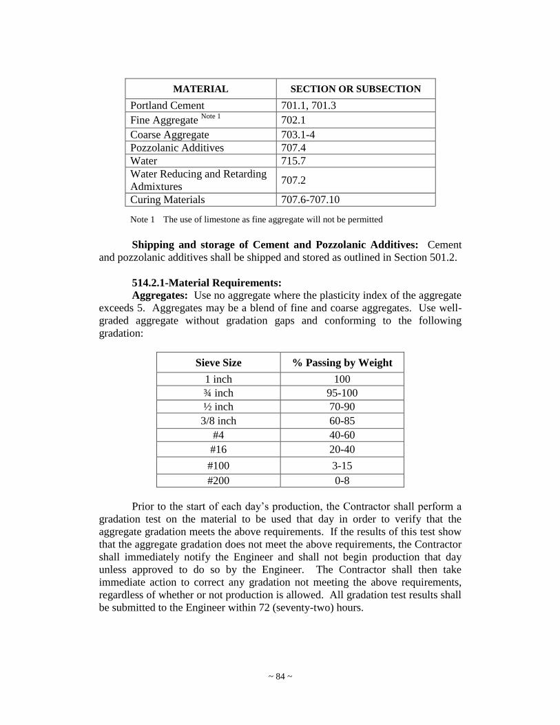
~ 84 ~
MATERIAL SECTION OR SUBSECTION
Portland Cement 701.1, 701.3
Fine Aggregate Note 1
702.1
Coarse Aggregate 703.1-4
Pozzolanic Additives 707.4
Water 715.7
Water Reducing and Retarding
Admixtures 707.2
Curing Materials 707.6-707.10
Note 1 The use of limestone as fine aggregate will not be permitted
Shipping and storage of Cement and Pozzolanic Additives: Cement
and pozzolanic additives shall be shipped and stored as outlined in Section 501.2.
514.2.1-Material Requirements:
Aggregates: Use no aggregate where the plasticity index of the aggregate
exceeds 5. Aggregates may be a blend of fine and coarse aggregates. Use well-
graded aggregate without gradation gaps and conforming to the following
gradation:
Sieve Size % Passing by Weight
1 inch 100
¾ inch 95-100
½ inch 70-90
3/8 inch 60-85
#4 40-60
#16 20-40
#100 3-15
#200 0-8
Prior to the start of each day‟s production, the Contractor shall perform a
gradation test on the material to be used that day in order to verify that the
aggregate gradation meets the above requirements. If the results of this test show
that the aggregate gradation does not meet the above requirements, the Contractor
shall immediately notify the Engineer and shall not begin production that day
unless approved to do so by the Engineer. The Contractor shall then take
immediate action to correct any gradation not meeting the above requirements,
regardless of whether or not production is allowed. All gradation test results shall
be submitted to the Engineer within 72 (seventy-two) hours.

~ 85 ~
514.3-PROPORTIONING:
514.3.1-RCC Mix Design Requirements:
At least 45 days prior to the start of construction, the Contractor shall submit
to the Engineer for approval the proportion of materials to be used which will
result in a workable RCC mix. No more than 25%, by mass, of the cementitious
material content of the RCC mix shall be pozzolanic materials. The Engineer
will review these proportions within 14 (fourteen) Calendar Days.
Laboratory density tests, in accordance with AASHTO T180 (Method D),
shall be performed during development of the mix design in order to determine
the maximum laboratory density and optimum moisture content for the RCC
mix. The material proportions used to achieve the maximum laboratory density
and the optimum moisture content shall be the material proportions used in the
approved mix design and during construction. Compressive strength tests, as
outlined in Section 514.3.2 shall be conducted on at least two separate batches of
RCC developed from these material proportions. The mix design results shall be
reported on the attachments for MP 711.03.23. The maximum laboratory
density and optimum moisture content shall be reported and included on the mix
design submittal also.
514.3.2-Design Compressive Strength: A mix design shall be used
which demonstrates a minimum compressive strength of 4500 psi within 28
days. Compressive strength specimens shall be prepared in accordance with
ASTM C1435 and tested in accordance with AASHTO T22. At least three
sets of three cylinders shall be produced, with one set being tested at 3 days,
one set being tested at 7 days, and the other at 28 days. The compressive
strength at a particular age shall be determined as the average of the three
specimens. If one individual result is much lower or much higher than the
other two due to defects in the specimen as outlined in section 601.4.4, that
value shall be discarded.
514.3.3-Design Moisture Content: A test for moisture content, in
accordance with ASTM C566, shall be performed on each of the RCC batches
produced in Section 514.3.1, from which compressive strength specimens
were fabricated. The average moisture content shall be considered the target
evaporable moisture content of the RCC mix, and shall be used for quality
control purposes as outlined in Section 514.4.2.1.
514.3.4-Test Section: If the mix design appears satisfactory to the
Engineer, the Contractor shall prepare and test a trial batch mixture and
representative test section at least 100 ft. (30 m) in length and 10 ft (3 m) in
width to verify that the design criteria for strength and density are met. The
criteria for strength and lift thickness shall be verified by the Contractor by
taking three cores at random locations and testing them in accordance with
AASHTO T24. The minimum required compressive strength for each of these

~ 86 ~
cores is 3,500 psi (24 Mpa), measured at an age no later than 28 days, or
within 10 percent of either the 3 or 7-day mix design strength, as determined
in Section 514.3.2. Density testing, as outlined in Section
514.4.2.3 shall be performed on this Test Section also. The minimum
required density for this testing is 98 percent of the maximum laboratory
density.
Perform batch mixture preparation and testing in the presence of
representatives of the Engineer. Construction, using RCC, shall not begin until
an approved mix design has been obtained.
The Test Section shall be located in a location approved by the Engineer. If
permitted by the Engineer, it is acceptable to place and leave the Test Section in
place as part of the completed pavement if it meets all of the above required
testing and acceptance criteria. If the Test Section is placed in an area which is
to be paved with RCC, and it does not meet all of the above acceptance criteria,
it shall be removed at the Contractor‟s expense.
514.4-TESTING:
514.4.1-Test Methods:
Standard Practice for Molding Roller-Compacted
Concrete in Cylinder Molds Using a Vibrating Hammer
ASTM C1435
Compressive Strength of Cylindrical Concrete
Specimens
AASHTO T22
Making and Curing of Concrete Specimens AASHTO T23
Obtaining and Testing Drilled Core Specimens AASHTO T24
Measuring Length of Drilled Concrete Cores AASHTO T148
Standard Test Method for Total Evaporable Moisture
Content of Aggregate by Drying
ASTM C566
Moisture-Density Relations of Soils using a 4.54 kg (10
lb.) Rammer and a 457 mm (18 inches) Drop
AASHTO T180
514.4.2-Contractor’s Quality Control:
514.4.2.1-RCC Moisture Content: The Contractor shall perform
moisture content tests in accordance with ASTM C566 on the initial batch
of RCC produced each day and then once again if the ambient temperature
reaches 85 °F (30 °C) or greater, as recorded in the vicinity of the
concrete production facility.
514.4.2.2-Testing for Opening Pavement to Traffic: A minimum of
three sets of compressive strength specimens shall be made for each day‟s
paving operation. These compressive strength specimens shall be
fabricated in accordance with ASTM C1435, and under the direct
observation of the Engineer. A set of specimens consists of three
cylinders. Field cure the specimens in accordance with AASHTO T23.

~ 87 ~
Test one cylinder from each set of these cylinders for compressive
strength in accordance with AASHTO T22 at each of the following ages
under the direct observation of the Engineer: 3 days, 5 days, and 7 days.
The compressive strength of each set of cylinders shall be the average of
the three specimens except that if one specimen shows evidence of
improper sampling, molding, or testing, it shall be discarded and the
remaining two strengths averaged. Should more than one specimen
representing a given test show definite defects due to improper sampling,
molding, or testing, the entire test shall be discarded.
The Contractor‟s personnel who fabricate the compressive strength
specimens shall provide evidence, prior to the start of construction and to
the satisfaction of the Engineer, that they are proficient in the specified
test methods.
RCC pavement at an age of 3, 5, or 7 days may be put into service if
the average compressive strength test result of the set of cylinders at the
corresponding age is at least 3,000 psi (21 Mpa).
The results of the 3 and 7 day quality control compressive strength
tests shall also be compared to the compressive strength results obtained in
Section 514.3.2. If the compressive strength of these quality control
specimens is less than 90% of the compressive strength results obtained in
Section 514.3.2, the Contractor shall investigate the potential causes of the
low strengths and report to the Engineer within 24 hours. If the
compressive strength of these quality control specimens is less than 80%
of the compressive strength results obtained in Section 514.3.2, and the
compressive strength is also less than 3,500 psi immediately stop
production and notify the Engineer. Do not resume production until the
cause of the discrepancy has been determined to the satisfaction of the
Engineer.
If the average strength of any of these sets of quality control cylinders,
representing a single day‟s production, is equal to or greater than 4,000 psi
(28 Mpa), then the Contractor is not required to test any of the remaining
quality control cylinders representing that day‟s production.
514.4.2.3-Density Testing: Field density tests for quality control shall
be performed by the contractor as soon as possible, but no later than 30
minutes after the completion of the rolling. The in-place density and
moisture content shall be determined using a properly maintained nuclear
moisture-density gauge in accordance with the applicable provisions of
MP 717.04.21. All testing shall be performed in direct transmission mode.
Only wet density is used for evaluation.
The testing shall be performed at a frequency not to exceed one test for
every 1,000 yd2 placed. The required minimum density is 98 percent of
the maximum laboratory density obtained according to AASHTO T 180
(Method D), as determined in Section 514.3.1. The gauge will be
calibrated for moisture content at the beginning of the work and at any
time during the work. Any lot of RCC which was properly placed and

~ 88 ~
compacted, but not meeting the density requirements based on the initial
testing, can be further evaluated by obtaining five additional randomly
located density tests within the lot in question. If the average of these five
additional tests meets the required minimum density, the lot shall be
considered acceptable.
If the lot has been determined to not meet the specified minimum
density requirements, it may be cored and tested by the Division in
addition to any coring performed for acceptance as per Section 514.4.3.1.
If the tested area achieves 3,500 psi (24 Mpa), it will be paid at the full
unit price. If the tested area indicates strength less than 3500 psi but
greater than 3150 psi, payment will be made as set forth in Table
514.4.2.3.
TABLE 514.4.2.3
Compressive Strength
(psi)
Price Reduction
(percent of unit bid price)
3300-3499 5
3150-3299 15
If the cores indicate strengths less than 3150 psi at 28 days or longer,
the Engineer will evaluate the results and may reject the affected area and
require removal and replacement or elect to pay at a reduced rate.
514.4.3-Acceptance Testing:
514.4.3.1-Compressive Strength Tests for Acceptance: The
compressive strength for acceptance of RCC will be determined by testing
cores. The RCC shall be at least 28 days old before the cores are obtained.
One 4-inch (100 mm) diameter core shall be obtained, by the Division, for
every 1,500 yd2 (1,250 m
2) or fraction thereof of RCC placed and represent
that area for acceptance purposes. These cores shall be tested by the Division
for compressive strength. The minimum required compressive strength of
these cores is 3,500 psi (24 Mpa).
The Contractor shall repair the core holes using concrete meeting the
requirements of Section 501 and shall rod and neatly strike off the repair
material.
Areas of RCC represented by any cores not meeting the minimum
compressive strength requirements shall be handled in accordance with
Section 105.12. Such areas that are allowed to remain in place shall be paid
for at a reduced unit bid price as outlined in Section 601.15.2, with the Design
Strength being 3,500 psi (24 Mpa).
Additionally, as outlined in Section 514.4.2.3, cores may also need to be
obtained to determine the compressive strength of any areas which are found
to not meet the specified density requirements. It should be noted that lot
sizes for density testing (1,000 yd2) and compressive strength acceptance
testing (1,500 yd2) are different, and will overlap throughout the project.

~ 89 ~
However, only one price adjustment shall be applied to any area not meeting
the specification requirements. If any lot, or portion of a lot, is determined to
have compressive strengths below 3,500 psi (24 Mpa) as outlined in Section
514.4.2.3 and is also found to be deficient in strength as outlined in Section
514.4.3.1, the price adjustment to be applied to that lot, or portion of that lot,
shall be the greater of either the price adjustments calculated accordingly.
514.4.3.2-Thickness Tests for Acceptance: The cores obtained in
Section 514.4.3.1 shall be measured for thickness, in accordance with
AASHTO T148, prior to being tested for compressive strength.
If the thickness of any core is found to be less than the specified design
thickness, then an evaluation of the area represented by that core shall be
performed by the Engineer in accordance with Section 105.12. If the
Engineer allows that area of deficient thickness to remain in place, then
that area shall be paid for at a reduced unit bid price as outlined in Table
514.4.3.2.
TABLE 514.4.3.2
Average Value of Pavement Thickness as
Represented by Acceptance Core
Unit Price As Percent of
Contract Unit Price
0.1 to 1.0% Less than Specified Thickness 98.0%
1.1 to 2.0 % Less than Specified Thickness 96.0%
2.1 to 3.0% Less than Specified Thickness 94.0%
3.1 to 4.0% Less than Specified Thickness 92.2%
4.1 to 5.0% Less than Specified Thickness 90.3%
5.1 to 6.0% Less than Specified Thickness 88.4%
6.1 to 7.0% Less than Specified Thickness 86.5%
More than 7.0% Less than Specified
Thickness, with a maximum of 0.70 inches
(18 mm) Less than Specified Thickness
Remove and Replace
514.4-EQUIPMENT AND TOOLS:
Construct roller compacted concrete with any combination of equipment
that will produce a completed pavement meeting the requirements for mixing,
transporting, placing, compacting, finishing, and curing as provided in this
specification.
514.4.1-Field Laboratory: RCC shall be supplied by a plant which has
been certified by the Division as meeting all requirements of the governing
Specifications and as having the facilities necessary to ascertain and control
the quality of the product in accordance therewith. A testing facility or
laboratory, meeting the requirements of Section 501.5.1 shall be provided by
the Contractor.

~ 90 ~
514.4.2-Mixing Plant:
514.4.2.1-General: Unless approved measures are taken to delay the
setting time of the RCC, the mixing plant shall be located within a thirty-
minute haul time from the point of RCC placement. Use only plants
capable of producing an RCC pavement mixture in the proportions defined
by the final approved mix design and within the specified tolerances. The
capacity of the plant must be sufficient to produce a uniform mixture at a
rate compatible with the placement equipment. The estimated production
rate of the Plant shall be noted in the Contractor‟s Quality Control plan. If
the plant is unable to produce material at a rate adequate to prevent
unnecessary cold joints and frequent paver stoppages, the Engineer may
halt production until such time that a plant of appropriate capacity is used.
The plant shall be inspected and approved by WVDOH District Materials
Personnel prior to production of material under these specifications.
514.4.2.2-Pugmill Plant: Use only pugmill plants of the central plant
type with a twin-shaft pugmill mixer, capable of batch or continuous
mixing, equipped with synchronized metering devices and feeders to
maintain the correct proportions of aggregate, cement, pozzolan, and
water. These plants shall meet the requirements of AASHTO M156.
Other pugmill plant requirements are as follows:
514.4.2.2.1-Aggregate Storage: If previously blended aggregate is
furnished, storage may be in a stockpile from which it is fed directly to a
conveyor feeding the mixer. If aggregate is furnished in two size groups,
follow proper stockpiling techniques in accordance with section 501.7 to
ensure aggregate separation.
514.4.2.2.2-Aggregate Feed Rate: Use aggregate bins with a feed
rate controlled by a variable speed belt, or an operable gate calibrated to
accurately deliver any specified quantity of material. If two aggregate size
stockpile sources are used, the feed rate from each bin must be readily
adjustable to change aggregate proportions, when required. Feed rate
controls must maintain the established proportions of aggregate from each
stockpile bin when the combined aggregate delivery is increased or
decreased.
514.4.2.2.3-Plant Scales: Plant scales, if utilized, for any weigh box
or hopper must comply with Section 601.5.2.3.
514.4.2.2.4-Cement and Pozzolan Material Storage: Supply
separate and independent storage silos for Portland cement and pozzolan.
At plants with two or more silos in which different types of cement or
cementitious materials are stored, ensure that each silo has a sign at each

~ 91 ~
fill inlet to reduce the potential for loading errors. Make the sign from a
durable material, with minimum two-inch high by ¼-inch wide letters that
are raised, indented, or cut. Ensure that the sign clearly identifies the
material that is in the silo and may be easily read even when completely
coated with dust.
514.4.2.2.5-Portland Cement and Pozzolan: If using Portland
cement and pozzolan (such as fly ash or slag), employ blending equipment
acceptable to the WVDOH and demonstrate, with a testing plan, the
ability to successfully produce a uniform blended material meeting the
mix design requirements. Perform testing on at least a daily basis to
ensure both uniformity and proper quantities.
514.4.2.2.6-Cement and Pozzolan Feed Unit: Provide a satisfactory
means of dispensing Portland cement and pozzolan, volumetrically or by
weight, to ensure a uniform and accurate quantity of cementitious material
enters the mixer.
514.4.2.2.7-Water Control Unit: Use a water control unit capable of
measuring the required amount of water for the approved mix by weight or
volume. Ensure that the unit is equipped with an accurate metering
device. Vary the amount of water to be used only with the approval of the
Engineer.
514.4.2.2.8-Gob Hopper: For continuous operating pugmills, provide
a gob hopper attached to the end of the final discharge belt to temporarily
hold the RCC discharge in order to allow the plant to operate
continuously.
514.4.2.3-Rotary Drum Mixer: Shall meet the requirements of
Section 501.5.3 and shall provide a rotary drum batch mixer capable of
producing a homogeneous mixture, uniform in color, and having all coarse
aggregate coated with mortar. Equip the mixer with batching equipment
to meet the following requirements:
514.4.2.3.1-Weighing Equipment: Measure the amounts of cement,
pozzolan, and aggregate entering into each batch of RCC by direct
weighing equipment. Use only weighing equipment that is readily
adjustable in order to compensate for the moisture content of the aggregate
or to change the proportionate batch weights. Include a visible dial or
equally suitable device that will accurately register the scale load from
zero to full capacity. The cement and pozzolan may be weighed
separately or cumulatively in the same hopper on the same scale, provided
the cement is weighed first.

~ 92 ~
514.4.2.3.2-Weigh Hoppers: Use only bulk cement and pozzolan
weigh hoppers that are equipped with vibrators to operate automatically
and continuously while weighing hoppers are being dumped. Ensure that
the weigh hopper has sufficient capacity to hold not less than 10 percent in
excess of the cementitious material required for one batch.
514.4.2.3.3-Water Metering: Measure the amount of water entering
each batch of RCC by weight or volume. Use only equipment capable of
measuring the water to within a tolerance of plus or minus one percent and
equipped with an accurate gauge or dial measuring device. Vary the
amount of water to be used only with the approval of the Engineer.
During batching, admit water to the mixer only through the water
measuring device and then only at the time of charging.
514.4.2.3.4-Mixing Time: Use only drum mixers equipped with an
accurate clock or timing device, capable of being locked, for visibly
indicating the time of mixing after all the materials, including the water,
are in the mixer.
514.4.2.3.5-Recharging: Discharge all material in the drum before
recharging. Ensure that the volume of mixed material per batch does not
exceed the manufacturer‟s rated capacity of the mixer.
514.4.3-Paver: Place RCC with a high-density asphalt-type paver subject
to approval by the Engineer. Use only pavers equipped with compacting
devices capable of producing an RCC pavement with a minimum of 90
percent of the maximum density in accordance with AASHTO T 180, Method
D prior to any additional compaction. Ensure that the paver is of suitable
weight and stability to spread and finish the RCC material, without
segregation, to the required thickness, smoothness, surface texture, cross-
section, and grade.
514.4.4-Compactors: Use self-propelled steel drum vibratory rollers
having a minimum static weight of 10 tons (9.1 Mg) for primary compaction.
For final compaction, use either a steel drum roller, operated in a static mode,
or a rubber-tired roller of equal or greater weight. Only use walk-behind
vibratory rollers or plate tampers for compacting areas inaccessible to large
rollers.
514.4.5-Haul Trucks: Use trucks for hauling the RCC material from the
plant to the paver with covers available to protect the material from inclement
weather and excessive evaporation. To ensure adequate and continuous
supply of RCC material to the paver, have a sufficient number of trucks. If
the number of trucks is inadequate to prevent frequent starts and stops of the
paver, cease production until additional trucks are obtained.
~ 93 ~
514.4.6-Water Trucks: Keep at least one water truck, or other similar
equipment, on-site and available for use throughout the paving and curing
process. Equip such equipment with a spreader pipe containing fog spray
nozzles capable of evenly applying a fine spray of water to the surface of the
RCC without damaging the final surface.
514.4.7-Inspection of Equipment: Before start-up, the Contractor‟s
equipment will be carefully inspected. Should any of the equipment fail to
operate properly, cease work until the deficiencies are corrected.
514.4.8-Access for Inspection and Calibration: Provide the Engineer or
WVDOH District Materials Inspector access at all times for any plant,
equipment, or machinery to be used in order to check calibration, scales,
controls, or operating adjustments.
514.5-PREPARATION OF GRADE AND CONDITIONING OF
SUBGRADE OR BASE:
Before the RCC processing begins, prepare the subgrade in accordance
with Section 228 of the WVDOH Standard Specifications.
514.6-HANDLING, MEASURING, AND BATCHING MATERIALS:
Handling, measuring, and batching of materials shall be in accordance
with Section 501.7, except that volumetric batching shall not be permitted.
514.7-MIXING RCC:
514.7.1-Mixing Process: Use the same mixture for the entire project
unless otherwise stated in the project documents. If, during production, the
source of Portland cement, pozzolan, or aggregates is changed, then suspend
production and submit a new mix design to the Engineer for approval. Do not
exceed the manufacturer's rated capacity for dry concrete mixtures in the
mixing chamber. Keep the sides of the mixer and mixer blades free of
hardened RCC or other buildups. Routinely check mixer blades for wear and
replace if wear is sufficient to cause inadequate mixing.
514.7.2-Mixing Time: Use a mixing time adequate to ensure a thorough
and complete mixing of all materials. Do not allow the mixing time, after all
materials including water are in the mixer, to be less than 1½ minutes for one
cubic yard (0.76 cubic meter) and 20 seconds for each additional cubic yard
(0.76 cubic meter).
514.7.3-Plant Calibration: Prior to commencement of RCC production,
carry out a complete and comprehensive calibration of the plant in accordance
with Section 501.5.2. Provide all scales, containers, and other items necessary
to complete the calibration. After completion of the initial calibration,

~ 94 ~
calibrate the plant periodically as directed by the Engineer. Plants listed on
WVDOH approved list at the time of RCC production are exempt from this
requirement, although the WVDOH reserves the right to require additional
calibration if variation in mixture quantities are suspected.
514.7.4-Daily Reports: Supply daily plant records of production and
quantities of materials used that day to the Engineer. These records may be
used as a check on plant calibration.
514.7.5-Transportation: Transport the RCC pavement material from the
plant to the areas to be paved in dump trucks equipped with retractable
protective covers for protection from rain or excessive evaporation. Ensure
that the trucks are dumped clean with no buildup or hanging of RCC material
in the corners. Have the dump trucks deposit the RCC material directly into
the hopper of the paver or into a secondary material distribution system that
deposits the material into the paver hopper. Dump truck delivery must be
timed and scheduled so that RCC material is spread and compacted within the
specified time limits.
514.8-PLACING RCC:
514.8.1-Subbase Condition: Prior to RCC placement, ensure that the
surface of the subbase is clean and free of foreign material, ponded water, and
frost. Ensure that the subbase is uniformly moist at the time of RCC
placement. If sprinkling of water is required to remoisten certain areas, ensure
that the method of sprinkling will not form mud or pools of freestanding
water. Correct soft or yielding subbase areas prior to placement of RCC as
specified in Section 6.1 above.
514.8.2-Adverse Weather Conditions:
514.8.2.1-Cold Weather Precautions: Employ cold weather
precautions as detailed in Section 601.9.1 of the Standard Specifications.
Stop placement operations when the air temperature falls below 40°F
(4.5°C) and is declining. Start operations only if the air temperature rises
above 35°F (1.7°C) and is elevating.
If the air temperature is expected to fall below 40°F (4.5°C) at some
time during construction, and if the Contractor plans to place RCC during
that time, the Contractor shall advise the Division of his plans for cold
weather curing and protecting the RCC. The Division may, at any time,
require the Contractor to provide additional protection to cause the
provisions of this specification to be met.
514.8.2.2-Hot Weather Precautions: Employ hot weather
precautions as detailed in Section 601.9.2 of the Standard Specification.
During periods of hot weather or windy conditions, take special

~ 95 ~
precautions to minimize moisture loss due to evaporation. Cooling of
aggregate stockpiles by shading or the use of a fine mist may be required.
Protective covers may be required on dump trucks. Keep the surface of
the newly placed RCC pavement continuously moist.
The Engineer may decrease the allowable time, specified in Section
514.9.1, between mixing and the completion of compaction when the
ambient temperature exceeds 90°F (32°C) or during windy conditions.
In no event shall RCC be placed when its temperature at any time after the
completion of mixing exceeds 90°F (32°C).
514.8.2.3-Rain Limitations: Conduct no placement of RCC
pavement during rain conditions sufficient to be detrimental to the finished
product. Placement may continue during light rain or mists provided the
surface of the RCC pavement is not eroded or damaged in any way. Use
dump truck covers during these periods. The WVDOH may terminate
paving at any time when, in the WVDOH judgment, the rain is detrimental
to the finished product.
514.8.3-Paver Requirements: Place all RCC with an approved paver as
specified in Section 514.5.3, and also meeting the requirements of this
Section.
514.8.3.1-Filling the Paver: Do not allow the quantity of RCC
material in the paver to approach empty between loads. Maintain the
material above the auger at all times during paving.
514.8.3.2-Stopping the Paver: Ensure that the paver proceeds in a
steady, continuous operation with minimal starts and stops, except to
begin a new lane. Maximum paver speed during laydown is 10 feet (3 m)
per minute. Higher paver speeds may be allowed at the discretion of the
WVDOH if the higher speeds may be obtained without distress to the final
product or cause additional starts and stops.
514.8.3.3-Surface Condition: Ensure that the surface of the RCC
pavement is smooth, uniform, and continuous without excessive tears,
ridges, or aggregate segregation once it leaves the paver.
514.8.4-Inaccessible Areas: Pave all areas inaccessible to either roller or
paver with cast-in-place concrete meeting the requirements of Section 501.
514.8.5-Adjacent Lane Pavement: Place adjacent paving lanes within
60 minutes. If more than 60 minutes elapses between placement of adjacent
lanes, the vertical joint must be considered a cold joint and prepared in
accordance with Section 514.10. At the discretion of the Engineer, this time
may be increased or decreased depending on ambient conditions of
~ 96 ~
temperature, wind, and humidity. Multiple pavers may be used in tandem to
reduce the occurrence of cold joints.
514.8.6-Hand Spreading: Broadcasting or fanning the RCC material
across areas being compacted is not permissible. Such additions of materials
may only be done immediately behind the paver and before any compaction
has taken place. Any segregated coarse aggregate shall be removed from the
surface before rolling.
514.8.7-Segregation: If segregation occurs in the RCC during paving
operations, placement shall cease until the cause is determined and corrected
to the satisfaction of the Engineer. If the segregation is judged by the
Engineer to be severe, remove and replace the segregated area at no additional
cost to the Department.
514.9-COMPACTION:
514.9.1-Time to Compaction Start: Ensure that compaction begins with
the placement process and is completed within 60 minutes of the start of the
mixing at the plant. The time may be increased or decreased at the discretion
of the WVDOH depending on ambient conditions of temperature and
humidity. Do not permit delays in rolling unless approved by the Engineer.
Plan operations and supply sufficient equipment to ensure that these criteria
are met.
514.9.2-Rolling: Determine the sequence and number of passes by
vibratory and non-vibratory rollers to obtain the specified density and surface
finish. Only operate rollers in the vibratory mode while in motion. Rubber-
tire rollers may be used for final compaction. Use additional rollers if specific
density requirements are not obtained or if placing operations get ahead of the
rolling operations.
514.9.3-Rolling Longitudinal and Transverse Joints: Do not operate
the roller within 2 feet of the edge of a freshly placed lane until the adjacent
lane is placed. Then, roll both edges of the two lanes together within the
allowable time. If a cold joint is planned, then roll the complete lane and
follow cold joint procedures as specified in Section 514.10.
514.9.4-Inaccessible Areas: Compact areas inaccessible to large rollers
using walk-behind rollers or hand tampers. Cast-in-place, meeting the
requirements of Section 501, may be used in these areas as a replacement for
RCC.

~ 97 ~
514.10-JOINTS:
514.10.1-Fresh Vertical Joints: A joint is considered a fresh joint when
an adjacent RCC lane is placed within 60 minutes of placing the previous lane
or as specified by the Engineer based on ambient conditions. Fresh joints do
not require special treatment.
514.10.2-Cold Vertical Joints: Any planned or unplanned construction
joints that do not qualify as fresh joints are considered cold joints. Prior to
placing fresh RCC mixture against a compacted cold vertical joint, thoroughly
clean the cold joint of loose or foreign material. Wet the vertical joint face
and maintain it in a moist condition immediately prior to placement of the
adjacent lane.
514.10.2.1-Sawing Cold Vertical Joints: For uncompacted surfaces or
slopes more than 15 degrees from the vertical, cut the joint vertically for the
full depth. Within 2 hours of final compaction, the edge of a cold joint may
be cut with approved mechanical equipment. For edges cut after 2 hours,
sawcut to the full depth of the pavement. Demonstrate any modification or
substitution of the sawcutting procedure to the WVDOH for approval prior to
use. In no case allow cutting of the edge to cause raveling or tearing of the
surface. Moisten the cut edge immediately prior to placement of the adjacent
lane.
514.10.3-RCC Pavement Joints at Structures: Line structures such as
manholes, valves, or concrete curb and gutter with joint filler as defined in
Section 708 of the Standard Specifications.
514.10.4-Control Joints: Construct transverse contraction joints in the
RCC pavement by sawing. At the option of the Contractor, soft-cut or green-
cut saws may be utilized as soon as possible behind the rolling operation and
set to manufacturer's recommendations. Conventional cut saws must be used
as soon as the sawing operation will not result in raveling or other damage to
the RCC pavement, but not more than 18 hours after RCC placement. Cut all
joints to 1/4 the depth of the RCC pavement to a single saw blade width.
Joints should be spaced at intervals not to exceed 24 times the nominal
pavement thickness unless otherwise indicated on the Plans or directed by the
WVDOH. (For example, for an 8-inch RCC pavement, cut joints at 16-foot
intervals.).
In areas where RCC is placed adjacent to existing concrete pavement, such
as in shoulder areas, the Contractor shall adjust the joint spacing to align with
the joints in the existing adjacent concrete pavement. In these areas, in order
to work out a joint spacing which aligns with the joints in the existing
pavement, the joints in the RCC may be spaced at intervals up to 24 times the
nominal RCC pavement thickness, plus 10 percent of that distance. (For
example, for an 8-inch RCC pavement, cut joints at a maximum spacing of
17.6-foot intervals).
~ 98 ~
514.11-FINISHING:
Ensure that the finished surface of the RCC pavement, when tested with a
10-foot straightedge or crown surface template, does not vary from the
straightedge or template by more than 1/4 inch at any one point and shall be
within 5/8 inch of the specified finished grade. When surface irregularities are
outside these tolerances, or other smoothness requirements specified in the plans,
diamond-grind the surface to meet the tolerance at no additional cost to the
WVDOH.
514.12-CURING:
Immediately after final rolling and compaction testing, keep the surface of
the RCC pavement continuously moist until an approved curing compound, a
suitable prime coat, or a layer of asphalt concrete is applied or for 72 hours after
placement, whichever comes first.
Until the RCC has achieved the required strength for opening to traffic,
the surface temperature of the RCC shall not be allowed to fall below freezing.
The Contractor shall be responsible for the quality of the RCC placed and cured
during cold weather. Any RCC injured by frost action shall be removed and
replaced at the Contractor‟s expense.
514.13.1-Water Cure: Apply water cure by water trucks equipped with
fog spray nozzles, soaking hoses, sprinkling system, or other means such that
a uniform moist condition on the surface of the RCC is ensured. Apply this
moisture in a manner that will not erode or damage the surface of the finished
RCC pavement.
514.13.2-Curing Compound: Do not use curing compounds when the
RCC material is to be promptly covered with asphalt. Apply curing
compound as indicated in Section 707.9 of the Standard Specifications, except
that the minimum rate of curing compound application is 11 square yards per
gallon (2.5 m2/L) unless a higher rate is specified by the curing compound
manufacturer.
514.13-OPENING TO TRAFFFIC:
Protect the RCC from vehicular traffic during the curing period. Do not
place vehicular traffic, except for curing equipment or sawcutting equipment, on
the RCC pavement until the RCC material achieves a minimum compressive
strength of 3,000 psi (21 Mpa) as demonstrated in Section 514.4.2.2.
514.14-MAINTENANCE:
Maintain the RCC pavement in good condition until all work is completed
and accepted. Perform such maintenance at no additional cost to the Engineer.

~ 99 ~
514.15-METHOD OF MEASUREMENT: The quantity of RCC placement to be paid for will be the number of
square yards (meters) complete in place and accepted. The width for
measurement will be the width of the pavement or overlay shown on the typical
cross section of the Plans and additional widening where called for or as
otherwise directed in writing by the Engineer. The length will be measured on the
surface along the centerline of the roadway or roadway ramp. Construction of
control joints will not be measured separately and no direct payment will be made
for this work.
514.16-BASIS OF PAYMENT: The quantities, determined as provided above, will be paid for at the
contract unit prices less adjustments referred to below and shall constitute full
compensation for furnishing and preparing of all materials, equipment, tools,
labor, and incidentals necessary to satisfactorily complete the work.
514.16.1-Thickness: Any sampling units found to be deficient in
thickness, and which are allowed to remain in place by the Engineer, shall be
paid for at a reduced Contract Unit Bid Price as outlined in Table 514.4.3.2.
No compensation will be allowed for the materials or labor involved in the
removal of defective material.
514.16.2-Strength: Determination of RCC strength shall be in
accordance with Section 514.4.3.1. Any sampling units found to be deficient
in strength, and which are allowed to remain in place by the Engineer, shall be
paid for at a reduced Contract Unit Bid Price as outlined in Section 514.4.3.1.
No compensation will be allowed for the materials or labor involved in the
removal of defective material.
514.16.3-Density: Determination of RCC density shall be in accordance
with Section 514.4.2.3. Any sampling units found to be deficient in density,
shall be handled in accordance with Sections 514.4.2.3 and 514.4.3.1.
514.17-PAY ITEM:
ITEM DESCRIPTION UNIT
514001-* “Thickness” ROLLER COMPACTED
CONCRETE Square Yard (Meter)
* Sequence number

~ 100 ~

~ 101 ~
DIVISION 600
INCIDENTAL CONSTRUCTION
SECTION 601
STRUCTURAL CONCRETE
601.1-DESCRIPTION:
ADD THE FOLLOWING SUBSECTION AFTER THE NINTH
PARAGRAPH:
Class DC concrete shall be used in drilled caisson foundations.
DELETE THE LAST PARAGRAPH AND SUBSTITUTE THE
FOLLOWING.
A hydration control stabilizing admixture may be used at the Contractor's
option provided that the conditions in section 601.7 are met.
601.2-MATERIALS:
ADD THE FOLLOWING TO THE TABLE:
MATERIAL SECTION OR SUBSECTION
Hydration Control Stabilizing
Admixtures 707.15
Specific Performance Admixtures 707.17
****Joint Filler (Substructure) 708.1.2
*****Joint Filler (Superstructure) 708.1.1
**** Joint filler for vertical joints in the substructure shall be in
accordance with Section 708.1.2.
***** Preformed joint filler for vertical joints in the superstructure
shall be sponge rubber in accordance with Section 708.1.1.

~ 102 ~
601.3-PROPORTIONING:
ADD THE FOLLOWING PARAGRAPH AT THE END OF THE SUB-
SECTION (AFTER THE FOURTH PARAGRAPH):
For establishment of mixture proportions, as an alternative to the curing
methods for rapid chloride permeability testing outlined in the previous paragraph,
specimens may be moist cured for 7 days in accordance with ASTM C 192, then
cured for 21 days in lime-saturated water at 100.0 ± 3.5 °F (38.0 ± 2.0 °C), then
tested at an age of 28 days. This method of curing shall be noted as the accelerated
RCPT curing method.
601.3.1-Mix Design Requirements:
ADD THE FOLLOWING AS THE SECOND PARAGRAPH IN THE
SUB-SECTION:
Approved Hydration Control Stabilizing Admixtures, as defined in Section
707.15, which are designed to stop the hydration of cement in a concrete mix,
enabling an extension to the allowable discharge time from a truck mixer as outlined
in Section 601.7, may be added to an existing approved concrete mix design in
accordance with the procedures outlined in MP 711.03.23.
ADD THE FOLLOWING LINES TO TABLES 601.3.1A {ENGLISH}
AND {METRIC}:
TABLE 601.3.1A
{ENGLISH}
Class of
concrete
Design 28 Day
Compressive
Strength
Target
Cement
Factor
Maximum
Water
Content
Standard Size of
Coarse
Aggregate***
Entrained
Air
Pounds per square
inch lbs./c.y. *
lb. of water /
lb. of cement
**
Number Percent
DC 4500 705 0.44 7, 78, or 8 6
TABLE 601.3.1A
{METRIC}
Class of
concrete
Design 28 Day
Compressive
Strength
Target
Cement
Factor
Maximum
Water
Content
Standard Size of
Coarse
Aggregate***
Entrained
Air
Mpa Kg/m3 *
L of water /
Kg of cement
**
Number Percent
DC 31 418 0.44 7, 78, or 8 6

~ 103 ~
*** A number 67 coarse aggregate may be used in Class DC concrete, provided
the Engineer approves the use of that size aggregate for the specific project on
which it is to be used. That approval will depend on the minimum spacing of
the reinforcing steel in the drilled caisson.
ADD THE FOLLOWING LINES TO TABLE 601.3.1B
TABLE 601.3.1B
MATERIAL CLASS OF
CONCRETE QUANTITY
Fly Ash DC 0.72 ft3 (0.020 m
3)
Ground Granulated
Furnace Slag DC 1.79 ft
3 (0.051 m
3)
601.3.2.3-Yield:
DELETE THE THIRD PARAGRAPH IN THE SECTION AND
REPLACE WITH THE FOLLOWING:
During the progress of the work, the actual yield shall be verified at
the frequency noted in MP 601.03.50; and, if the yield, based on a single
unit weight determination, should differ from the theoretical yield by more
than plus or minus two percent, two additional unit weight determinations
shall be made, and the average of the three determinations shall be
considered the unit weight of the concrete. The actual yield shall be
determined from that average unit weight, and the design mix shall be
adjusted as required to correct the actual yield to correspond to the
theoretical yield.
601.3.2.4-Total Solids Ā:
ADD THE FOLLOWING PARAGRAPH AFTER THE FIFTH
PARAGRAPH IN THE SUBSECTION AS PARAGRAPH SIX:
When the small quantity work condition applies, the Ā required after
50 cubic yards (37.5 cubic meters) of concrete production shall be
performed on the day that the 50 cubic yard quantity is achieved. All
concrete produced on that day (the day that the 50 cubic yard quantity is
achieved) shall be represented by the previous Ā. The Ā conducted on the
day that the 50 cubic yard quantity is achieved shall represent the next 50
cubic yards of concrete produced, beginning with the concrete produced
on the next day of production.
ADD THE FOLLOWING AT THE END OF THE SUBSECTION AS
PARAGRAPHS EIGHT AND NINE:

~ 104 ~
When, in a concrete mix, gradations tests show that the percentage of
material which passes the No. 200 (75 µm) sieve, exceeds the amount
permitted in Sections 702.1.2 and 703.4, and provided the Engineer
permits the material to remain in place and the Contractor elects to leave
the material in place, then a penalty shall be applied in the manner
outlined in the following paragraph.
It shall be determined which material (coarse aggregate, fine
aggregate, or both) caused the total material finer than the No. 200 (75
µm) sieve to exceed the specification limits as determined in Sections
702.1.2 and 703.4. The mass of the material(s) in the concrete mix (Mca,
Mfa, or both, as defined in MP 601.03.51), which caused the total material
finer than the No. 200 (75 µm) sieve to exceed the specification limits
shall be divided by Mt (as defined in MP 601.03.51). The resulting
number shall be multiplied by the unit price of the concrete, as billed by
the Concrete Supplier and by the quantity of non-specification concrete
placed. That value shall be the penalty applied for the use of the material
which did not meet the specification requirements.
601.4-TESTING:
601.4.1-Sampling and Testing Methods:
DELETE THE LAST TWO PARAGRAPHS FROM THE SECTION:
ADD THE FOLLOWING LINE AT THE END OF THE TABLE:
Rapid Chloride Permeability Test AASHTO T 277
601.4.2-Contractor’s Quality Control:
INSERT THE FOLLOWING PARAGRAPH AT THE END OF THE
SECTION:
The Contractor shall provide a copy of the quality control test results to
the Supplier of the concrete which was tested within 48 hours of the
completion of the test.
601.4.5-Tests for permeability acceptance:
DELETE THE HEADING AND THE FIRST SENTENCE OF THE
FIRST PARAGRAPH AND REPLACE WITH THE FOLLOWING:
601.4.5-Tests for permeability acceptance of Class H concrete: The
Contractor shall be required to compare the compressive strength test results
obtained in Section 601.4.4, for Class H concrete, to the compressive strength
of the approved test mix per Section 601.3.
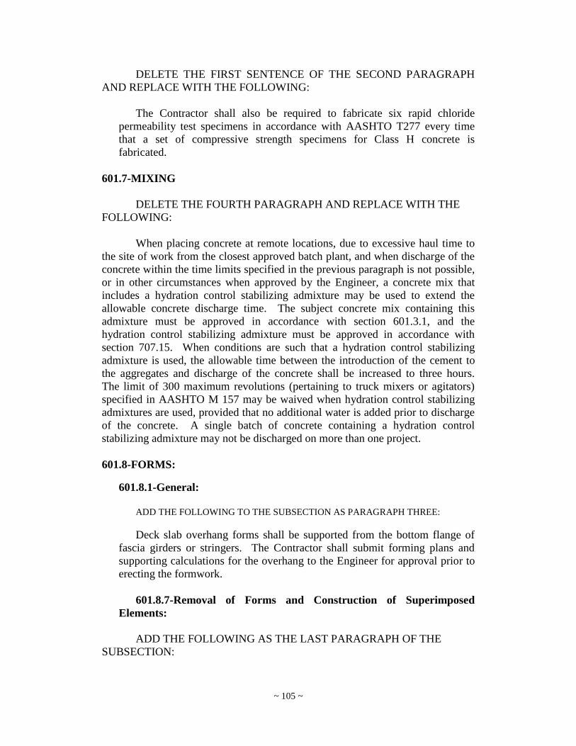
~ 105 ~
DELETE THE FIRST SENTENCE OF THE SECOND PARAGRAPH
AND REPLACE WITH THE FOLLOWING:
The Contractor shall also be required to fabricate six rapid chloride
permeability test specimens in accordance with AASHTO T277 every time
that a set of compressive strength specimens for Class H concrete is
fabricated.
601.7-MIXING
DELETE THE FOURTH PARAGRAPH AND REPLACE WITH THE
FOLLOWING:
When placing concrete at remote locations, due to excessive haul time to
the site of work from the closest approved batch plant, and when discharge of the
concrete within the time limits specified in the previous paragraph is not possible,
or in other circumstances when approved by the Engineer, a concrete mix that
includes a hydration control stabilizing admixture may be used to extend the
allowable concrete discharge time. The subject concrete mix containing this
admixture must be approved in accordance with section 601.3.1, and the
hydration control stabilizing admixture must be approved in accordance with
section 707.15. When conditions are such that a hydration control stabilizing
admixture is used, the allowable time between the introduction of the cement to
the aggregates and discharge of the concrete shall be increased to three hours.
The limit of 300 maximum revolutions (pertaining to truck mixers or agitators)
specified in AASHTO M 157 may be waived when hydration control stabilizing
admixtures are used, provided that no additional water is added prior to discharge
of the concrete. A single batch of concrete containing a hydration control
stabilizing admixture may not be discharged on more than one project.
601.8-FORMS:
601.8.1-General:
ADD THE FOLLOWING TO THE SUBSECTION AS PARAGRAPH THREE:
Deck slab overhang forms shall be supported from the bottom flange of
fascia girders or stringers. The Contractor shall submit forming plans and
supporting calculations for the overhang to the Engineer for approval prior to
erecting the formwork.
601.8.7-Removal of Forms and Construction of Superimposed
Elements:
ADD THE FOLLOWING AS THE LAST PARAGRAPH OF THE
SUBSECTION:
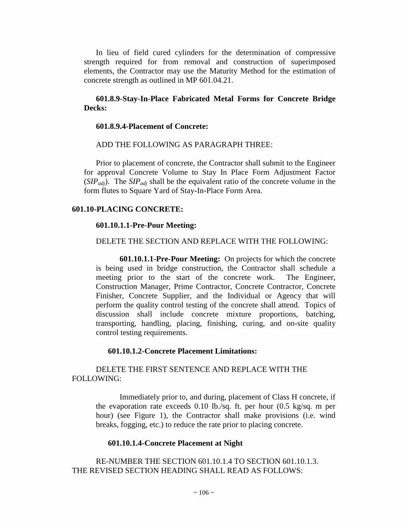
~ 106 ~
In lieu of field cured cylinders for the determination of compressive
strength required for from removal and construction of superimposed
elements, the Contractor may use the Maturity Method for the estimation of
concrete strength as outlined in MP 601.04.21.
601.8.9-Stay-In-Place Fabricated Metal Forms for Concrete Bridge
Decks:
601.8.9.4-Placement of Concrete:
ADD THE FOLLOWING AS PARAGRAPH THREE:
Prior to placement of concrete, the Contractor shall submit to the Engineer
for approval Concrete Volume to Stay In Place Form Adjustment Factor
(SIPadj). The SIPadj shall be the equivalent ratio of the concrete volume in the
form flutes to Square Yard of Stay-In-Place Form Area.
601.10-PLACING CONCRETE:
601.10.1.1-Pre-Pour Meeting:
DELETE THE SECTION AND REPLACE WITH THE FOLLOWING:
601.10.1.1-Pre-Pour Meeting: On projects for which the concrete
is being used in bridge construction, the Contractor shall schedule a
meeting prior to the start of the concrete work. The Engineer,
Construction Manager, Prime Contractor, Concrete Contractor, Concrete
Finisher, Concrete Supplier, and the Individual or Agency that will
perform the quality control testing of the concrete shall attend. Topics of
discussion shall include concrete mixture proportions, batching,
transporting, handling, placing, finishing, curing, and on-site quality
control testing requirements.
601.10.1.2-Concrete Placement Limitations:
DELETE THE FIRST SENTENCE AND REPLACE WITH THE
FOLLOWING:
Immediately prior to, and during, placement of Class H concrete, if
the evaporation rate exceeds 0.10 lb./sq. ft. per hour (0.5 kg/sq. m per
hour) (see Figure 1), the Contractor shall make provisions (i.e. wind
breaks, fogging, etc.) to reduce the rate prior to placing concrete.
601.10.1.4-Concrete Placement at Night
RE-NUMBER THE SECTION 601.10.1.4 TO SECTION 601.10.1.3.
THE REVISED SECTION HEADING SHALL READ AS FOLLOWS:

~ 107 ~
601.10.1.3-Concrete Placement at Night:
601.11-FINISHING CONCRETE SURFACES:
EDIT AND RE-NUMBER THE SECTION AS FOLLOWS:
601.11.4-Finishing Concrete Bridge Decks: Any addition of water to
the surface of the concrete to assist in the finishing operations will not be
permitted. When conditions are such that unusually rapid drying is occurring,
an atomized mist may be used to prevent the rapid evaporation of water from
the concrete surface during the final finishing.
601.11.4.1-Class K Bridge Decks: After striking off, consolidating,
and floating have been completed, both while the concrete is still plastic,
the surface shall be checked for trueness with a straightedge. The
Contractor shall furnish an accurate scraping type straightedge with a
minimum length of 10 feet (3.048 meters) and swung from a handle at
least 3 feet (1 meter) longer than one-half the width of the slab.
The straightedge shall be held in successive positions parallel to the
road centerline and in contact with the roadway surface and operated from
side to side until the surface is within the permissible tolerance provided.
Advance along the roadway shall be in successive stages of not more than
one-half of the length of the straightedge. Any depressions found shall be
immediately filled with freshly mixed concrete, struck-off, consolidated,
and refloated. High areas shall be cut down and refloated. The
straightedge testing and reflecting shall continue until the surface is found
to be free from observable departures from the straightedge and the slab
has the required grade and contour.
Upon completion of the above operations, the surface shall be
smoothed with a lute or smoothing float, 4 to 6 feet (1.2 to 1.8 meters) in
length, after which the surfaces shall be tested with an accurate
straightedge. This checking straightedge shall be 10 feet (3.048) meters
long and shall be held in a position parallel to the centerline of the
roadway. The advance of this straightedge along the slab shall be in
successive stages of not more than one-half of its length. When tested
with this straightedge, the finished surface shall be free from observable
departures from the straightedge.
Upon completion of the above operations, the surface of the concrete
shall be given a groove finish while the concrete is still plastic. The tool
used shall produce a groove that is approximately 3/32 inch (2 mm) wide.
The depth of this groove shall be 1/8 inch (3 mm) to 3/16 inch (5 mm) and
spaced approximately ½ inch (13 mm) center to center. The grooves shall
be formed in a direction that is transverse to the centerline of the roadway
or parallel to the skew. On any one bridge the direction of the grooves
shall be consistent. Adjacent strokes to establish the texture shall abut one
another without appreciable overlap. Texturing shall be performed when
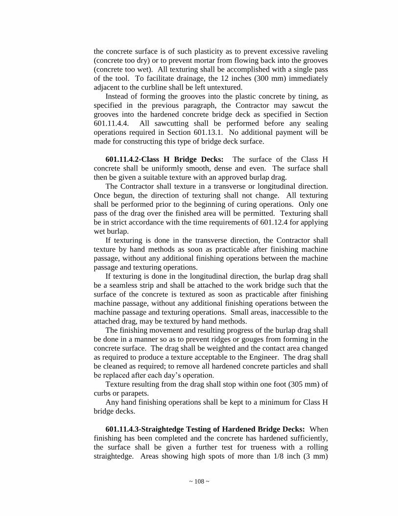
~ 108 ~
the concrete surface is of such plasticity as to prevent excessive raveling
(concrete too dry) or to prevent mortar from flowing back into the grooves
(concrete too wet). All texturing shall be accomplished with a single pass
of the tool. To facilitate drainage, the 12 inches (300 mm) immediately
adjacent to the curbline shall be left untextured.
Instead of forming the grooves into the plastic concrete by tining, as
specified in the previous paragraph, the Contractor may sawcut the
grooves into the hardened concrete bridge deck as specified in Section
601.11.4.4. All sawcutting shall be performed before any sealing
operations required in Section 601.13.1. No additional payment will be
made for constructing this type of bridge deck surface.
601.11.4.2-Class H Bridge Decks: The surface of the Class H
concrete shall be uniformly smooth, dense and even. The surface shall
then be given a suitable texture with an approved burlap drag.
The Contractor shall texture in a transverse or longitudinal direction.
Once begun, the direction of texturing shall not change. All texturing
shall be performed prior to the beginning of curing operations. Only one
pass of the drag over the finished area will be permitted. Texturing shall
be in strict accordance with the time requirements of 601.12.4 for applying
wet burlap.
If texturing is done in the transverse direction, the Contractor shall
texture by hand methods as soon as practicable after finishing machine
passage, without any additional finishing operations between the machine
passage and texturing operations.
If texturing is done in the longitudinal direction, the burlap drag shall
be a seamless strip and shall be attached to the work bridge such that the
surface of the concrete is textured as soon as practicable after finishing
machine passage, without any additional finishing operations between the
machine passage and texturing operations. Small areas, inaccessible to the
attached drag, may be textured by hand methods.
The finishing movement and resulting progress of the burlap drag shall
be done in a manner so as to prevent ridges or gouges from forming in the
concrete surface. The drag shall be weighted and the contact area changed
as required to produce a texture acceptable to the Engineer. The drag shall
be cleaned as required; to remove all hardened concrete particles and shall
be replaced after each day‟s operation.
Texture resulting from the drag shall stop within one foot (305 mm) of
curbs or parapets.
Any hand finishing operations shall be kept to a minimum for Class H
bridge decks.
601.11.4.3-Straightedge Testing of Hardened Bridge Decks: When
finishing has been completed and the concrete has hardened sufficiently,
the surface shall be given a further test for trueness with a rolling
straightedge. Areas showing high spots of more than 1/8 inch (3 mm)

~ 109 ~
shall be marked by the Engineer and, only when directed by the Engineer,
such areas shall be ground with an approved grinding tool, utilizing
carborundum stones or industrial diamond wheels; grinding shall be done
to an elevation where the area or spot will not show a surface deviation in
excess of 1/8 inch (3 mm) when tested with the 10 feet (3.048 meter)
rolling straightedge, except that the maximum depth of grinding shall not
exceed ¼ inch (6 mm). The ground areas shall be treated as directed by
the Engineer. Where the initial deviation from the straightedge is ½ inch
(13 mm) or more, the Contractor will be required to remove and replace
the complete pour in which the areas not meeting the required tolerance
are located.
After grinding, all areas either high or low, not meeting the
requirements of 1/8 inch (3 mm) tolerance will be measured and
disposition of these areas will be as set forth in 601.15.2.
ADD THE FOLLOWING SUBSECTION:
601.11.4.4-Class H Concrete Finished Deck Grooving: After
completion of water curing the concrete and after corrective grinding, but
before opening the bridge to traffic, saw longitudinal or transverse grooves
in accordance with the following applicable subsection.
601.11.4.4.1-Transverse Grooving: After corrective grinding and
before opening to traffic, grooves shall be cut into the concrete using a
mechanical saw. These grooves shall be 0.10 inch (3 mm) wide and 0.25
inch (6 mm) deep. Groove spacing shall be 1.5 inches (38 mm) center to
center. No later than one week prior to grooving operations, the Contractor
shall provide the Engineer with two accurate, easily readable gauges with
which to verify groove dimensions. Groove depth and spacing tolerances
are limited to ±1/16 inch (±2 mm). Groove width tolerances are +0.02
(+0.5 mm) inch and -0.0 inch (-0 mm). The grooves shall be cut in a
direction that is transverse to the centerline of the roadway or parallel to
the skew. On any one bridge the direction of the grooves shall be
consistent. Grooves shall be cut continuously across the deck to within one
foot (305 mm) of gutter lines or drainage structures. Grooves shall also be
continuous across the full width of the deck surface including construction
joints. Grooves shall terminate within 1 inch (25 mm) of any exposed
metal component or elastomeric concrete of an expansion joint. When the
deck is skewed and the contractor is using gang blades to saw the grooves,
the maximum distance (measured perpendicular to the centerline of the
expansion joint) from the last groove termination in the pass to the
expansion joint shall be 1 foot - 8 inches (508 mm). Radial grooving shall
be performed in increments limited to 12 feet (3.7 m) of bridge length.
601.11.4.4.2-Longitudinal Grooving: Use diamond blades mounted
on a multi-blade arbor on self-propelled machines that were built for

~ 110 ~
grooving of concrete surfaces. The groove machines shall have depth
control devices that detect variations in the pavement surface and adjust
the cutting head height to maintain the specified depth of the groove. The
grooving machines shall have devices to control alignment. Do not use
flailing or impact type grooving equipment. More than one size grooving
machine may be required in order to saw the grooves as specified.
Provide an experienced technician to supervise the location, alignment,
layout, dimension, and grooving of the surface.
Saw grooves parallel to the bridge centerline in a continuous pattern
across the surface. Begin and end sawing 9 to 12 inches (220 to 300 mm)
from any device in place in a bridge deck, such as scuppers or expansion
joints. Stop sawing a minimum of 2 inches (50 mm) to a maximum of 24
inches (600 mm) from skewed expansion joints. Maintain a clearance of a
minimum of 2 inches (50 mm) and a maximum of 4 inches (100 mm) from
the grooves to longitudinal joints in the deck. Maintain a minimum
clearance of 9 inches (220 mm) to a maximum of 30 inches (750 mm)
clearance between the grooves and the curb or parapet toe. However, at no
point shall un-grooved portions of deck extend beyond edge line and into
the temporary or permanent travelled lanes. Saw grooves in a uniform
pattern spaced at 3/4 inch minus 1/4 inch or plus 0 inches (19 mm minus 6
mm or plus 0 mm). Saw grooves 0.15 inches (4 mm) deep and 0.10 inches
(3 mm) wide. Groove tolerances for depth are +0.0625 inches (2 mm) and
minus 0 inches (0 mm). Groove tolerances for width are +0.02 inches (0.5
mm) and minus 0 inches (0 mm).
For staged, or phased bridge deck work, saw the grooves parallel to the
final, permanent bridge centerline. If the different stages or phases of the
bridge deck work occur within one construction season, any stage opened
to traffic shall receive an interim coarse broom finish during placement,
then saw the longitudinal grooves after the final stage. The interim broom
finish will not be allowed as a surface texture when opened to traffic over
a winter season. Saw longitudinal grooves in the deck prior to opening to
traffic for a winter season.
For bridge decks that widen from one end to the other, saw the
longitudinal grooves parallel to the centerline of the roadway. On the side
of the bridge that widens, saw the longitudinal grooves to follow the edge
line. Saw longitudinal grooves in the gore areas, avoiding the overlapping
of grooves.
At the beginning of each work shift, furnish a full complement of
grooving blades with each saw that are capable of cutting grooves of the
specified width, depth, and spacing.
If during the work, a single grooving blade on a machine becomes
incapable of cutting a groove, continue work for the remainder of the work
shift. The Contractor is not required to cut the groove omitted because of
the failed blade. Should two or more grooving blades on a machine
become incapable of cutting grooves, cease operating the machine until it
is repaired.

~ 111 ~
Continuously remove all slurry and remaining residue from the
grooving operation and leave the deck surface in a clean condition.
Prevent residue from grooving operations from flowing across shoulders
or across lanes occupied by public traffic or from flowing into gutters or
other drainage facilities. Remove solid residue before the residue is blown
by passing traffic or by wind.
Provide water as necessary to saw grooves according to this
subsection.
601.12-CURING AND PROTECTING CONCRETE:
601.12.1-Curing Under Normal Conditions:
ADD THE FOLLOWING AFTER THE FIFTH SENTENCE OF THE
SECOND PARAGRAPH:
The contractor shall not be permitted to add additional cement to the target
cement factor in the approved mix design in order to obtain high-early
strength and/or reduce curing time.
601.12.3-Protection of Finished Surfaces:
ADD THE FOLLOWING TO THE END OF THE FIRST PARAGRAPH:
Water runoff from concrete curing operations shall be deflected away
from the steel girders and shall not drain onto the substructure concrete after
contacting the weathering steel.
601.12.4-Curing Class H Concrete
DELETE THE SECOND PARAGRAPH AND REPLACE WITH THE
FOLLOWING:
The concrete surface shall be completely covered with clean, wet burlap. The
burlap shall be thoroughly saturated over its entire area, but shall be drained of
excess water before application. Burlap shall be lapped a minimum of one foot
(305 mm) and shall lay flat. Failure to apply wet burlap within 30 minutes after
discharge of the concrete from the truck and within 10 minutes of the completion
of finishing operations shall be cause for rejection of the work as determined by
the Engineer. Care shall be exercised to ensure that the burlap is well drained.
Burlap shall be continuously wet for a period of seven days by means of automatic
intermittent sprinkling or a continuous wetting system.
ADD THE FOLLOWING TO THE SECTION:

~ 112 ~
601.12.5-Protecting Concrete Decks: Construction equipment with an axle
load greater than 20,000 lbs (20 kips) shall not be permitted on bridge deck.
Construction equipment or loads that are not required to complete the slab,
parapets, railing overlay, or other appurtenances shall not be allowed on the
bridge deck.
601.13-PROTECTIVE SURFACE TREATMENT:
601.13.1-Linseed Oil
DELETE THE SUB-SECTION AND RENAME AND REPLACE WITH
THE FOLLOWING:
601.13.1-Silane Treatment for Bridge Superstructure: After the
concrete has achieved a minimum of 80% of the design strength, a silane
protective treatment as specified shall be applied to the entire top surface of
bridge decks, approach slabs when they are included in the Contract, concrete
bridge medians, top and curb face of bridge sidewalks, and the inside faces of
parapets. When approach slabs are specified to be overlayed with asphalt, the
silane treatment is not required.
The application of this silane protective surface treatment is not required
for elements constructed from Class H concrete.
The surface to receive the treatment shall be dry for at least 48 hours
before treatment and shall be free from sand, surface dust and dirt, oil, grease,
chemical films, and other contaminants prior to application of the silane.
Immediately before application, the entire surface shall be air blown to
remove any loose dust. The surface, air, and material temperatures shall be
between 40 and 100° F during application, and temperatures above 40° F,
without precipitation, must be forecast for the twelve hours following
application. Any coating damaged by rain or moisture shall be corrected by
an additional application.
The surface treatment shall consist of one of the silane sealers listed on the
Division‟s Approved Product List of Concrete Sealers.
The surface treatment, including application rate, shall be applied in
accordance with the requirements listed above and the Manufacturer‟s
recommendations.
Metal hand rails shall be protected from spray by shielding or masking.
The Contractor shall prohibit all pedestrian and vehicular traffic on the
structure during the drying period of the protective coating.
601.13.1.1-Silane Treatment for Bridge Substructure: Before placing
any steel superstructure members on the concrete substructure units, the
Contractor shall coat all exposed areas of the abutment, tops, sides, and all
faces of pier caps and pier stems to the ground or water line elevation with an
approved silane based concrete sealer except for projects where concrete

~ 113 ~
protective or other coatings are specified. Preparation of surfaces, application
rates, and methods shall be as recommended by the silane manufacturer.
Upon completion of all superstructure concrete curing operations, the
Contractor shall remove all stains from substructure units using proprietary
chemical stain removers and/or mild acid etching. Abrasive blast cleaning
shall be used to supplement the other cleaning methods to completely remove
all stains if the stained areas are severe or extensive. All cleaning methods
shall be subject to approval of the Engineer.
Re-coat all areas where stains were removed, regardless of the cleaning
method used, with an approved silane based concrete sealer as specified
above.
601.13.3-Concrete Protective Coating:
ADD THE FOLLOWING TO THE SECTION:
This section shall apply only when the pay item for concrete protective
coating is included in the plans.
601.13.3.1-Concrete Surface Preparation:
DELETE THE FIRST PARAGRAPH AND REPLACE WITH THE
FOLLOWING:
After the Engineer has inspected and accepted the concrete surfaces of
bridges and median barriers as having a satisfactory ordinary surface finish,
clean the concrete surfaces specified hereinafter of all dust, rust, foreign
matter, and form oil, and apply a Department approved protective coating
finish. Coat the following surfaces, including all beveled edges:
601.14-METHOD OF MEASUREMENT:
DELETE THE FIRST PARAGRAPH AND REPLACE WITH THE
FOLLOWING:
The quantity of work done for Classes A, B, C, D, H, K, and M concrete
will be measured in cubic yards (meters), complete in place and accepted as
determined by the dimensions on the Plans or Contract Documents, subject to
adjustments provided for in Sections 104.2 and 109.2.
DELETE PARAGRAPH TWO AND REPLACE WITH THE
FOLLOWING:
The quantity of work done for Class H and Class K concrete will be
measured in cubic yards (meters), complete in place and accepted, as measured
from one end of the bridge to the other, fascia to fascia, and from the top of the
forms to the finished elevation of the proposed deck surface. The volume of

~ 114 ~
concrete required to fill the flutes of stay-in-place forms shall be calculated by
taking the Contractor‟s approved SIPadj factor and multiplying by the square
yardage of SIP area minus beam widths, expansion dam widths, etc. as applicable.
601.15-BASIS OF PAYMENT:
601.15.1-General:
DELETE PARAGRAPH ONE AND REPLACE WITH THE
FOLLOWING:
The quantities, determined as provided above, will be paid for at the
contract unit prices bid or at the adjusted percent of contract price as specified
for the items listed below, which prices and payments shall be full
compensation for furnishing all the materials and doing all the work
prescribed in a workmanlike and acceptable manner, including all labor, tools,
equipment, joint filler, field laboratory, supplies and incidentals necessary to
complete the work.
601.16-PAY ITEMS
DELETE THE FOLLOWING ITEMS FROM THE TABLE:
ITEM NUMBER DESCRIPTION UNIT
6010025-001 Modified Concrete, Class CY
6010026-001 Modified Architectural Concrete, Class CY
ADD THE FOLLOWING ITEMS TO THE TABLE:
ITEM NUMBER DESCRIPTION UNIT
601002-002 Class B Concrete, Mass CY
601025-002 Modified Concrete, Class A CY
601025-003 Modified Concrete, Class B CY
601025-004 Modified Concrete, Class B Mass CY
601025-005 Modified Concrete, Class C CY
601025-006 Modified Concrete, Class D CY
601025-007 Modified Concrete, Class H CY
601025-008 Modified Concrete, Class K CY
601026-002 Modified Architectural Concrete, Class B CY
601026-003 Modified Architectural Concrete, Class H CY
601026-004 Modified Architectural Concrete, Class K CY

~ 115 ~
SECTION 602
REINFORCING STEEL
602.6-PLACING AND FASTENING:
602.6.1-General:
INSERT THE FOLLOWING AS PARAGRAPH TWO:
The clear distance between the reinforcing steel and the face of the
concrete unless otherwise shown in the plans shall be:
Top of deck slab: 2.5”
Bottom of deck slab: 1.0”
Bottom of footings 3.0”
All other locations 2.0”
602.7-BAR SPLICES:
602.7.1-Lapping:
DELETE THE SECTION AND REPLACE WITH THE FOLLOWING:
602.7.1-Lapping: All reinforcement shall be furnished in full lengths as
indicated on the Plans. No splicing of bars, except where shown on the Plans,
will be permitted without the written approval of the Engineer. Lapped
splices shall be well distributed or located at points of low tensile stress. The
bars shall be rigidly clamped or wired at all splices in a manner approved by
the Engineer. Minimum lengths of lap splices unless otherwise noted shall be:
#4 Bar 1‟-9”
#5 Bar 2‟-2”
#6 Bar 2‟-9”
#7 Bar 3‟-9”
#8 Bar 4‟-11”
#9 Bar 6‟-2”
#10 Bar 7‟-10”
#11 Bar 9‟-7”
For epoxy coated bars, the minimum lap splice length shall be increased
by 50 percent at locations where concrete cover is less than 3 bar diameters
and 20 percent at all other locations.

~ 116 ~
SECTION 603
PRESTRESSED CONCRETE MEMBERS
603.6.5-Strength of Concrete:
ADD THE FOLLOWING PARAGRAPH AT THE END OF THE SUB-
SECTION:
Whenever the compressive strength of a member at 28-days is less than
the 28-day design compressive strength value, the subject member may still be
accepted without a price adjustment if the compressive strength at any time
prior to shipment (up to a maximum of 56-days from the date of fabrication)
exceeds the 28-day design compressive strength value. The Division shall not
be responsible for any project delays incurred due to the delayed strength
attainment, and time extensions under Section 108 of the Specifications are
not applicable to this scenario.
DELETE THE SUBSECTION AND REPLACE WITH THE FOLLOWING:
603.14.2.1 – Price Adjustments:
Members found not in compliance with the requirements of 603.6.5 for
compressive strength, but for which the evaluation indicates may still be
used, will be paid for at a reduced price in accordance with the following
formulas, depending on who purchased the members:
FORMULA 1: Use the following price reduction formula when the
members are used in a project constructed by a Contractor:
Price Reduction =
'
_'
5.0 c
c
f
Xf x 40% of the Contract Unit Bid Price
FORMULA 2: Use the following price reduction formula when the
beams are used in a project constructed by the Division:
Price Reduction =
'
_'
5.0 c
c
f
Xf x IC
Where:
'
cf = 28-Day Design Compressive Strength, psi (Mpa)
_
X = Average 28-day Compressive Strength as determined in 603.6.5
IC(Formula 2 only) = The invoiced cost of the member itself, as billed to the
Division by the Fabricator. This cost shall not include
other items associated with the member such as
guardrail, bearing pads, etc.
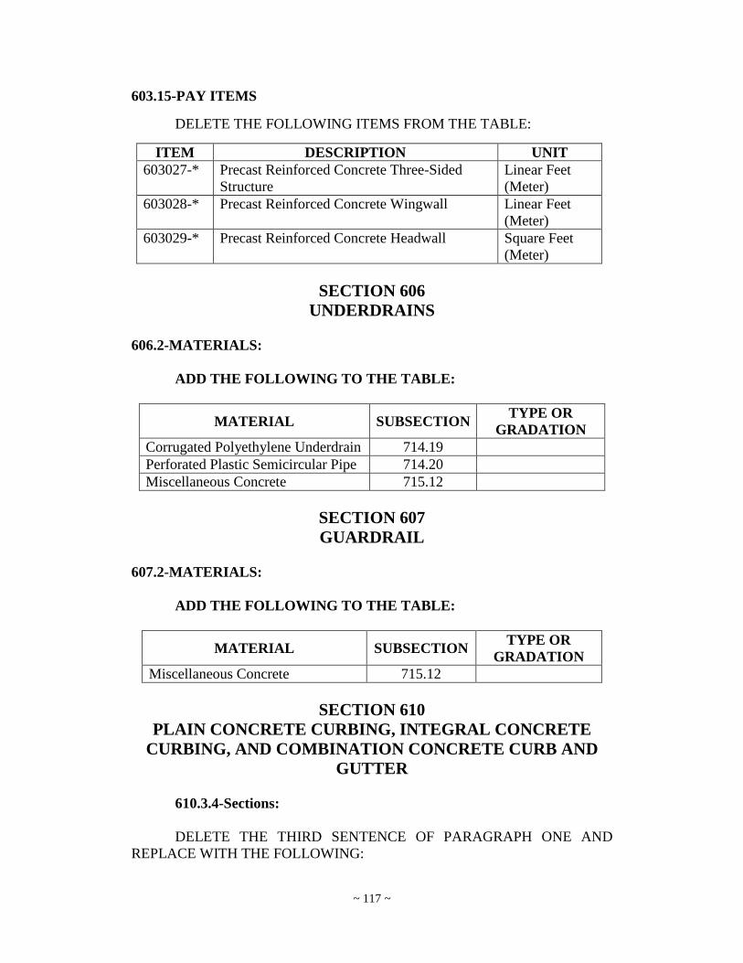
~ 117 ~
603.15-PAY ITEMS
DELETE THE FOLLOWING ITEMS FROM THE TABLE:
ITEM DESCRIPTION UNIT
603027-* Precast Reinforced Concrete Three-Sided
Structure
Linear Feet
(Meter)
603028-* Precast Reinforced Concrete Wingwall Linear Feet
(Meter)
603029-* Precast Reinforced Concrete Headwall Square Feet
(Meter)
SECTION 606
UNDERDRAINS
606.2-MATERIALS:
ADD THE FOLLOWING TO THE TABLE:
MATERIAL SUBSECTION TYPE OR
GRADATION
Corrugated Polyethylene Underdrain 714.19
Perforated Plastic Semicircular Pipe 714.20
Miscellaneous Concrete 715.12
SECTION 607
GUARDRAIL
607.2-MATERIALS:
ADD THE FOLLOWING TO THE TABLE:
MATERIAL SUBSECTION TYPE OR
GRADATION
Miscellaneous Concrete 715.12
SECTION 610
PLAIN CONCRETE CURBING, INTEGRAL CONCRETE
CURBING, AND COMBINATION CONCRETE CURB AND
GUTTER
610.3.4-Sections:
DELETE THE THIRD SENTENCE OF PARAGRAPH ONE AND
REPLACE WITH THE FOLLOWING:
~ 118 ~
Sections shall be separated by joints 1/8 in. (3mm) wide except at
expansion joints.
SECTION 614
PILING WALLS
614.8-METHOD OF MEASUREMENT
DELETE THE CONTENTS OF THE SECTION AND REPLACE WITH
THE FOLLOWING:
The quantity of piles will be measured in linear feet (meters) of piles
installed and accepted for the wall.
The quantity of lagging will be measured in square feet (meters) installed
and accepted as measured by the total area of wall as measured through all wall
elements, without deductions for gaps between lagging, piles, etc.
SECTION 615
STEEL STRUCTURES
615.3-MATERIALS:
615.3.2-High-Strength Fasteners:
DELETE PARAGRAPH ONE AND REPLACE WITH THE
FOLLOWING:
Bolts, nuts, and washers shall conform to Section 709.24 and shall be
mechanically galvanized in accordance with ASTM B695. Hot-dip
galvanizing or coating with a zinc rich primer may be used only when
specified by the Contract documents.
INSERT THE FOLLOWING SUBSECTION:
615.3.2.1-Weathering Steel Bridges: High strength fasteners shall meet
Section 709.24 and shall be Type 3 (weathering steel), per ASTM A325.
High strength fasteners used in regions of the structure that require painting
shall be Type 1 or 3, per ASTM A325, and mechanically galvanized in
accordance with ASTM B695.
615.3.7-Coating of Anchor Bolts, Nuts and Washers:
DELETE PARAGRAPH ONE AND REPLACE WITH THE
FOLLOWING:

~ 119 ~
All anchor bolts, nuts and washers shall be hot dip galvanized in
accordance with AASHTO M232 after fabrication.
615.4-FABRICATION:
REPLACE THE FOLLOWING SUBSECTION:
615.4.2-Storage of Materials: Steel members must not be gouged,
scratched, dented, or allowed to rub against other members that would result
in damage to the steel member or coating. Members shall be handled using
softeners and slings instead of chokers and chains.
Store members in the fabrication shop and on the project site in such a
manner as to be kept free and clean of all foreign substances such as grease,
oil, mortar and concrete splatter , chalk and crayon marks, paint, and dirt. All
storage must be above ground and sloped to allow free drainage of melted
snow, rainwater, and dew. If the members are stored for periods longer than
three months, the members must be placed on metal supports. For a period of
storage up to three months, members may be placed on clean, untreated wood
timbers. Do not allow treated lumber or treated timber to contact steel
members.
Store plate girders and rolled beams with the web in the upright position.
The members may be stacked on metal or wood supports provided, as noted
above; individual members must be kept separate. Under no circumstances
shall members be nested together or bundled.
615.5-ASSEMBLY:
615.5.7-Welding:
INSERT THE FOLLOWING AS PARAGRAPHS TWO AND THREE:
No field welding is permitted unless shown on the plans or approved by
the Engineer.
Exercise caution while making field or shop welds while an elastomeric
bearing pad is in contact with the steel. In no case shall the elastomer or
elastomer band be exposed to instantaneous temperatures greater than 400
degrees F. Any damage to the elastomeric bearing due to welding will be
cause for rejection. The temperature shall be monitored by heat crayons
furnished by the Contractor.
615.6-ERECTION:
INSERT THE FOLLOWING SECTION:

~ 120 ~
615.6.9-Final Cleaning Of Weathering Steel Bridges: Upon
completion of all concrete curing operations, the contractor shall clean
all steel surfaces to remove all grease, oil, concrete residue, dirt, and
other foreign substances to the satisfaction of the Engineer.
Cleaning may be by high pressure water, powered or hand wire
brushing, or by Brush off Blast Cleaning according to SSPC-SP 7.
Cleaning shall be followed by a clean water rinse to remove all residues
of detergents and cleaners if they were used. All grease and oil shall be
removed prior to the clean water rinse by solvent cleaning.
Do not use acids to remove stains.
Areas of the shop applied paint system which are damaged during
erection and high strength bolted connection areas that were only prime
painted shall be properly cleaned and painted according to Section 688
of the Standard Specification, PAINTING STEEL STRUCTURES, and
to the satisfaction of the Engineer.
After completion of all tightening operation, mechanical galvanized
fasteners shall be solvent cleaned and field painted as specified for the
structural steel.
For integral or semi-integral abutment structures, the
crevice/interface between the embedded steel and the concrete shall be
suitably chamfered to provide for placement of a sealant. Sealant
material shall meet the requirements of ASTM C920, Type S, Grade
NS, Class 25, Uses NT and M. Sealant shall be suitable for bonding
between concrete and the top coat of the specified paint system. Acid-
cure sealants shall not be permitted.
SECTION 620
THREE-SIDED REINFORCED CONCRETE
BRIDGE/CULVERT
620.2-GENERAL:
DELETE THE FIRST TWO PARAGRAPHS IN THE SECTION:
SECTION 625
DRILLED CAISSON FOUNDATIONS
DELETE THE SUBSECTION AND REPLACE WITH THE
FOLLOWING:

~ 121 ~
625.4.1-Concrete: Concrete for the drilled caissons shall be Class DC
and shall conform to the requirements of Section 601 of the Standard
Specifications.
The design 28-day compressive strength shall not be less than 4500 psi (31
Mpa) unless shown otherwise in the Plans. The Contractor shall prepare a mix
design in accordance with MP 711.023.23 to attain this strength. Slump for dry
placement will be 7 inches (175 mm) plus-or-minus 1 inch (25 mm). Unless
otherwise specified in the Plans, the cement shall be Type I.
For placement of caisson concrete by tremie or pumping, the cement
factor shall be increased by 94 lbs. (43 kg) from the original design cement factor,
the slump shall be 8 inches (200 mm) plus-or-minus 1 inch (25 mm) and shall
maintain a slump in excess of 4 inches (100 mm) throughout the concrete
placement.
SECTION 626
RETAINING WALL SYSTEMS
DELETE THE SECOND PARAGRAPH AND REPLACE WITH THE
FOLLOWING:
626.5-MATERIALS:
626.5.1.1.2.3-Sealers shall be silane and/or siloxane based and
specifically formulated for use on porous surfaces such as concrete block.
Sealers shall be tested in accordance with ASTM E514 on a block
wall, and shall provide a minimum of 90% reduction in leakage.
Three dry-cast concrete block specimens shall be treated with the
sealer and tested for absorption in accordance with ASTM C140. The
sealer shall provide a minimum of 90% reduction in water absorption
when tested in this manner.
626.5.3.1-Test Requirements:
REVISE THE TABLE REFERENCED IN PARAGRAPH ONE TO SAY
THE FOLLOWING:
Sieve Size Percent Passing
4 inches (100mm) 100
No. 40 (425 µm) 0-60
No. 200 (75 µm) 0 - 15
REVISE NOTE (**) OF BULLET D., TO SAY THE FOLLOWING:
** May be adjusted if geosynthetic material is used for soil reinforcements
or attachment devices see shop drawings and section 626.5.1.1.6.
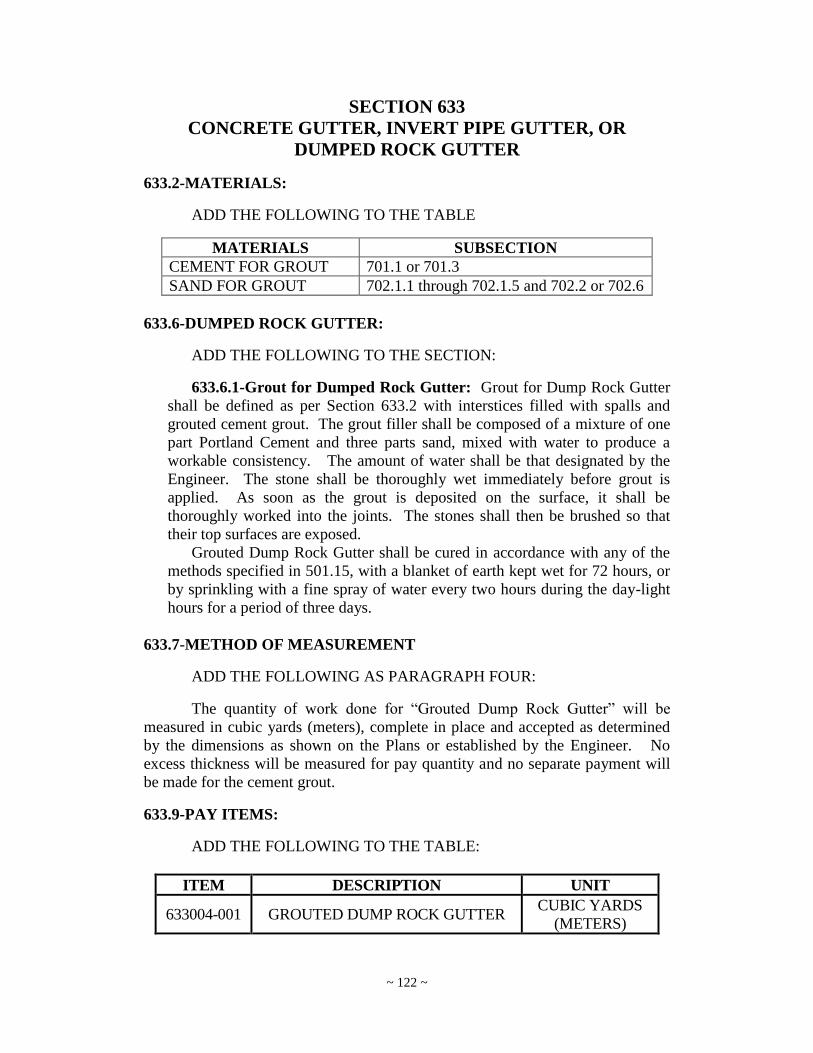
~ 122 ~
SECTION 633
CONCRETE GUTTER, INVERT PIPE GUTTER, OR
DUMPED ROCK GUTTER
633.2-MATERIALS:
ADD THE FOLLOWING TO THE TABLE
MATERIALS SUBSECTION
CEMENT FOR GROUT 701.1 or 701.3
SAND FOR GROUT 702.1.1 through 702.1.5 and 702.2 or 702.6
633.6-DUMPED ROCK GUTTER:
ADD THE FOLLOWING TO THE SECTION:
633.6.1-Grout for Dumped Rock Gutter: Grout for Dump Rock Gutter
shall be defined as per Section 633.2 with interstices filled with spalls and
grouted cement grout. The grout filler shall be composed of a mixture of one
part Portland Cement and three parts sand, mixed with water to produce a
workable consistency. The amount of water shall be that designated by the
Engineer. The stone shall be thoroughly wet immediately before grout is
applied. As soon as the grout is deposited on the surface, it shall be
thoroughly worked into the joints. The stones shall then be brushed so that
their top surfaces are exposed.
Grouted Dump Rock Gutter shall be cured in accordance with any of the
methods specified in 501.15, with a blanket of earth kept wet for 72 hours, or
by sprinkling with a fine spray of water every two hours during the day-light
hours for a period of three days.
633.7-METHOD OF MEASUREMENT
ADD THE FOLLOWING AS PARAGRAPH FOUR:
The quantity of work done for “Grouted Dump Rock Gutter” will be
measured in cubic yards (meters), complete in place and accepted as determined
by the dimensions as shown on the Plans or established by the Engineer. No
excess thickness will be measured for pay quantity and no separate payment will
be made for the cement grout.
633.9-PAY ITEMS:
ADD THE FOLLOWING TO THE TABLE:
ITEM DESCRIPTION UNIT
633004-001 GROUTED DUMP ROCK GUTTER CUBIC YARDS
(METERS)
~ 123 ~
SECTION 636
MAINTAINING TRAFFIC
636.5-TEMPORARY STRUCTURES:
DELETE THE CONTENTS OF THE SECTION AND REPLACE WITH
THE FOLLOWING:
Temporary structures shall be constructed and maintained as shown on the
Plans or as called for in the Proposal. The use of used material is acceptable;
Such material shall be inspected visually and accepted by the Engineer prior to its
use. The design and plans for the temporary structure shall be in accordance to
Section 105.2.
ADD THE FOLLOWING SUBSECTION:
636.12-TEMPORARY IMPACT ATTENUATING DEVICE:
This device shall be a “stationary crash cushion” as described within
Section F.82 of the manual “Manual On Temporary Traffic Control For Streets
And Highways, 2006 Edition”.
The device utilized shall be a model listed on the WVDOH Approved
Products Listing (APL) for Safety Devices specifically noted as being approved
for temporary work zone use. Specific device selection in regards to manufacturer
and model shall be at the Contractor‟s discretion; however, unless the
characteristics of the obstacle to be shielded dictate otherwise, the device utilized
shall be a non-tapered, non-gating device. If it is not possible, based on the width
of the obstacle to be shielded, to utilize a non-tapered, non-gating device, the
Contractor shall utilize an approved Sand Barrel system.
Notes included on the APL characterize non-gating devices by their
National Cooperative Highway Research Program Report 350 (NCHRP-350)
crash testing approval level (Test Level 2 or Test Level 3). The Test Level
certification required for each particular device to be qualified at shall be based on
the normal (non work zone) posted speed limit in effect at the location of the
device. A Test Level 2 or Test Level 3 device shall be utilized if the normal
posted speed limit is 40 MPH or less. Otherwise, a Test Level 3 device shall be
required. Sand Barrel arrays shall be designed for an impact speed 5 MPH greater
than the normal posted speed limit.
All Temporary Impact Attenuating Devices shall be installed and
maintained fully in accordance with the specifications and recommendations of
the device manufacturer. This shall include, but shall not be limited to,
characteristics of the roadway profile along the approach to the nose of the device
and along the adjacent (traffic) side of the device, changes in the roadway grade
within the length of the device, side slope and changes in the side slope at the
location of the device, anchoring (base to be anchored to as well as the anchoring
system), backup, attachment to the obstacle being shielded, transitioning to the
obstacle being shielded, winterization, delineation, repair, and cleaning. If the

~ 124 ~
installation requires deviations from the specifications and recommendations of
the device manufacturer, the Contractor shall obtain written approval from the
device manufacturer and shall produce this written approval for review upon
request.
Impacted devices shall be maintained and returned to full impact capacity
in a timely manner. Beginning 12 hours from the time and date upon which the
Contractor is given documented notice of damage to an Impact Attenuating
Device requiring repairs, the Contractor shall be subject to a penalty of $1,000 per
Calendar Day (24 hrs.), or fraction thereof, until the necessary repairs are
completed. This penalty shall not be temporarily suspended for any reason and
shall apply regardless of the cause of the damage to the device.
All labor, equipment, and materials required for the repair of impact
attenuating devices shall be incidental to Bid Item 636060.
636.14-TEMPORARY CONCRETE BARRIER:
DELETE THIS ENTIRE SECTION AND TITLE AND REPLACE WITH
THE FOLLOWING:
636.14-TEMPORARY BARRIER:
Furnish, install, maintain, remove and dispose of temporary barrier in
accordance with this specification and the contract plans.
636.14.1-Materials: Temporary Barrier shall meet the requirements of
NCHRP Report 350 and/or MASH-08 for the different test levels as shown in
Table 3.1 “Test Matrix for Longitudinal Barriers” in NCHRP Report 350.
Specific types of temporary barrier will not be used unless crash tested and
approved by the Engineer. Historical performance will help determine use of a
product. Poor performance may be grounds for non-acceptance.
Based on past performance, existing temporary concrete barrier with pin
and eye connections are considered acceptable up to and including test level
TL-3, until January 1, 2016
Temporary Barriers shall have adequate drainage slots to allow runoff to
pass through.
Temporary Barrier shall have 8” x 12” Type B-1 Delineators (white or
yellow as appropriate) facing traffic at 40 foot centers.
636.14.2-Installation: This barrier type shall conform to the details on
the Plans, set as directed on the Plans, with the barrier sections securely
connected together by satisfactory fastening devices to provide a more stable
structure against impact.
A Temporary Barrier Installation Plan shall be approved according to
Section 105.2.1.2 “Contractor Approval Method”. It shall have information
adequate to ensure it meets the installation conditions below and shall include
barrier type, barrier connection type, NCHRP test approval and data,
individual segment length, anchorage details, end treatments, and transition
details.

~ 125 ~
The temporary barrier shall be placed to match test conditions as
determined by the Engineer. These conditions may include, but not be limited
to, anchorages, total length of barrier, individual segment length and
connection details. Only one type of temporary barrier shall be used for any
one continuous run of barrier in a project. To clarify, the entire length of
temporary barrier shall not be intermixed in regard to type of barrier,
connection type, or individual barrier length unless that configuration has
been tested.
Anchorage spacing and installation, if required, shall be per manufacturer
subject to shop drawing review and approval and meet or exceed test
conditions. Shop drawing information shall include details for anchor
removal and patching and /or repair of pavement or bridge deck.
Where temporary barrier adjoins guardrail barrier, regardless if one is
temporary and the other is permanent (newly constructed or previously in
existence) or if both are temporary, they must be connected with a Temporary
Guardrail Connector conforming to 636.16.2.
Where temporary barrier adjoins bridge parapet or other essentially non-
yielding barrier or obstacle, they must be joined in a manner to maintain
barrier continuity and prevent vehicle snagging during impact. If they cannot
be joined in this manner, a connection device must be used to assure barrier
continuity and to prevent vehicle snagging during impact.
When the temporary barriers are no longer needed, they will become the
property of the Contractor, unless otherwise noted on the Plans.
J-J Hook connections shall be tensioned by pulling the barrier segments
apart to make this type connection “tight”.
Vehicles, materials or any other equipment shall not be stored in the
Temporary Barrier buffer area. Unless required as a part of the contract,
vehicles and equipment shall not work in the Temporary Barrier buffer area
and if required, shall be limited to that time that it is necessary to be in that
area.
636.15-REMOVING AND RESETTING TEMPORARY CONCRETE
BARRIERS:
DELETE THIS ENTIRE SECTION AND REPLACE WITH THE
FOLLOWING:
636.15-REMOVING AND RESETTING TEMPORARY BARRIERS:
Temporary barriers that are to be relocated within a project shall be
salvaged and reinstalled as specified in 636.14 and set as indicated on the Plans.
636.23-METHOD OF MEASUREMENT:
636.23.4-Temporary Structures:
DELETE THE CONTENTS OF THE SUBSECTION AND REPLACE
WITH THE FOLLOWING:

~ 126 ~
"Temporary Structures for Maintaining Traffic", as detailed on the Plans
or called for by the Engineer, shall be on a lump sum basis for completing,
maintaining and removal of the work. Earthwork required for erection or
removal of the structure, not measured and paid for by a specific item, shall
not be measured or paid for and shall be incidental to Item 636005-*,
Temporary Structure For Maintaining Traffic.
636.23.17-TEMPORARY CONCRETE BARRIER:
DELETE THE HEADING CONTENTS. REPLACE WITH THE
FOLLOWING:
636.23.17-Temporary Barrier: The quantity of “Temporary Barrier”
shall be the linear feet (meters) of barrier actually placed. Payment shall
include terminal connecting devices, delineators, anchoring, maintaining,
dismantling, removal and disposal of the barrier and devices when no further
use is required.
636.23.18-Removing and Resetting Temporary Concrete Barrier:
DELETE THE SECTION AND REPLACE WITH THE FOLLOWING:
636.23.18-Removing and Resetting Temporary Barrier: The quantity
of “Removing and Resetting Temporary Barrier” shall be the linear feet
(meters) of barrier reused in a different location. Payment shall include
temporary storage if necessary, re-erecting, maintaining, dismantling, removal
and disposal of the barrier.
ADD THE FOLLOWING SUBSECTION:
636.23.27-Temporary Impact Attenuating Device: One unit of
“Temporary Impact Attenuating Device” shall be paid at the time of initial
installation of a device, as described in Section 636.12, at each unique
location within the project. However, over the life of the project the
Contractor shall not be paid for a quantity of this item exceeding the
maximum number of individual devices required to be in place on the project
at a specific time. Each installation beyond this quantity shall be paid for
using the “Remove And Reset Attenuator Device” item.
ADD THE FOLLOWING SUBSECTION:
636.23.28-Remove and Reset Attenuator Device: This item shall be
measured and paid for in accordance with the provisions of Section 636.23.27.
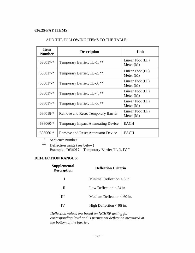
~ 127 ~
636.25-PAY ITEMS:
ADD THE FOLLOWING ITEMS TO THE TABLE:
Item
Number Description Unit
636017-* Temporary Barrier, TL-1, ** Linear Foot (LF)
Meter (M)
636017-* Temporary Barrier, TL-2, ** Linear Foot (LF)
Meter (M)
636017-* Temporary Barrier, TL-3, ** Linear Foot (LF)
Meter (M)
636017-* Temporary Barrier, TL-4, ** Linear Foot (LF)
Meter (M)
636017-* Temporary Barrier, TL-5, ** Linear Foot (LF)
Meter (M)
636018-* Remove and Reset Temporary Barrier Linear Foot (LF)
Meter (M)
636060-* Temporary Impact Attenuating Device EACH
636060-* Remove and Reset Attenuator Device EACH
* Sequence number
** Deflection range (see below)
Example: “636017 Temporary Barrier TL-3, IV ”
DEFLECTION RANGES:
Supplemental
Description Deflection Criteria
I Minimal Deflection < 6 in.
II Low Deflection < 24 in.
III Medium Deflection < 60 in.
IV High Deflection < 96 in.
Deflection values are based on NCHRP testing for
corresponding level and is permanent deflection measured at
the bottom of the barrier.
~ 128 ~
SECTION 638
PROJECT MARKERS, RIGHT-OF-WAY MARKERS,
AND SURVEY MARKERS
DELETE THE HEADING AND REPLACE WITH THE FOLLOWING:
SECTION 638
PROJECT MARKERS, RIGHT-OF-WAY MARKERS, SURVEY MARKERS, AND OUTLET MARKERS
638.1-DESCRIPTION:
DELETE THE FIRST PARAGRPAH AND REPLACE WITH THE
FOLLOWING:
This work shall consist of furnishing, and placing or installing at the
points designated on the Plans, in the Contractor‟s Proposal or by the Engineer,
metal (signpost) project markers, right-of-way markers, concrete survey markers,
and outlet markers in accordance with these Specifications and in reasonably
close conformity to the lines, grades, dimensions, locations, and sections shown
on the Plans, in the Contractor‟s Proposal or established by the Engineer.
638.2-MATERIALS:
ADD THE FOLLOWING AS THE THIRD PARAGRAPH:
The materials for Outlet Marker Signs, such as for the sign panels, their
supports, and for the legend and background, are to be of a type and method of
fabrication that will be consistent with the conditions and estimated period of use.
Signs shall have black letters for the legend on a white background. Reflective
sheeting will be permitted, but not required.
DELETE SECTIONS: 638.6, 638.7, AND 638.8 AND REPLACE WITH
THE FOLLOWING:
638.6-OUTLET MARKERS:
638.6.1-General: Outlet Markers Signs shall be furnished by the
Contractor and placed during the mobilization of the project. The Outlet Marker
Sign shall be in accordance with Figure 638.6.1 below. . The Outlet Marker
Signs shall become the property of the Division and remain in place upon
completion of the project unless otherwise directed by the Engineer. No shop
drawings shall be required.
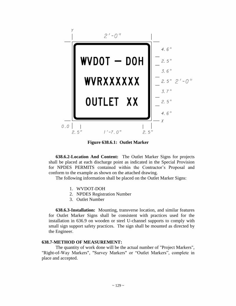
~ 129 ~
Figure 638.6.1: Outlet Marker
638.6.2-Location And Content: The Outlet Marker Signs for projects
shall be placed at each discharge point as indicated in the Special Provision
for NPDES PERMITS contained within the Contractor‟s Proposal and
conform to the example as shown on the attached drawing.
The following information shall be placed on the Outlet Marker Signs:
1. WVDOT-DOH
2. NPDES Registration Number
3. Outlet Number
638.6.3-Installation: Mounting, transverse location, and similar features
for Outlet Marker Signs shall be consistent with practices used for the
installation in 636.9 on wooden or steel U-channel supports to comply with
small sign support safety practices. The sign shall be mounted as directed by
the Engineer.
638.7-METHOD OF MEASUREMENT:
The quantity of work done will be the actual number of "Project Markers",
"Right-of-Way Markers", "Survey Markers" or “Outlet Markers”, complete in
place and accepted.
~ 130 ~
638.8-BASIS OF PAYMENT:
The quantities, determined as provided above, will be paid for at the
contract unit prices bid for the items listed below, which prices and payments
shall be full compensation for excavating, backfilling, disposing of surplus
material, furnishing all the material and doing all the work prescribed in a
workmanlike and acceptable manner, including all labor, tools, equipment,
supplies, and incidentals necessary to complete the work.
638.9-PAY ITEMS:
ADD THE FOLLOWING TO THE TABLE:
ITEM DESCRIPTION UNIT
638004-* OUTLET MARKER EACH
*Sequence number
SECTION 640
FIELD OFFICE AND STORAGE BUILDING
640.4-FIELD OFFICE
640.4.1-General:
DELETE PARAGRAPH TWO OF THE SUBSECTION AND REPLACE
WITH THE FOLLOWING:
The office shall be provided with an approved type of heating and cooling
equipment that will maintain a comfortable seasonable temperature
throughout the project life. It shall be furnished with satisfactory electric
lighting and lighting service. A minimum of two duplex convenience outlets
shall be provided in each room. The building shall be provided with neat,
sanitary, enclosed toilet with exhaust fan accommodations for the exclusive
use of the Engineer, and such facilities shall meet the requirements of the
State Department of Health or other authorities having jurisdiction. It shall be
stocked with lavatory and sanitary supplies at all times during the period of
the contract. Additionally the Contractor shall provide, maintain, and pay for
internet access via service such as Cable, DSL, Satellite or other system along
with a wireless router for the field office. The wireless router and internet
specifications such as minimum upload and download speeds can be located
at the following WVDOH website:
http://www.transportation.wv.gov/highways/contractadmin/specifications/
640.11fieldoffice/Pages/default.aspx

~ 131 ~
SECTION 642
TEMPORARY POLLUTION CONTROL
642.6-TEMPORARY PIPE, CONTOUR DITCHES, BERMS, SLOPE
DRAINS, DITCH CHECKS, SILT FENCE AND
PREMANUFACTURED DITCH CHECKS:
DELETE AND REPLACE WITH THE FOLLOWING HEADING:
642.6-TEMPORARY PIPE, CONTOUR DITCHES, BERMS, SLOPE
DRAINS, DITCH CHECKS, SILT FENCE, PREMANUFACTURED
DITCH CHECKS AND SUPER SILT FENCE:
ADD THE FOLLOWING SUBSECTION:
642.6.8-Super Silt Fence: Fence shall be in accordance with the latest
specifications for Section 608: Right-of-Way Fence. The details shall be as
shown in the latest version of the standards detail book: Standard Detail F4
(Sheet 1 of 2) except as noted below:
Once sedimentation has reached half of the Super Silt Fence height, all
accumulated sediment shall be removed and disposed of as directed by the
Engineer.
The Contractor shall inspect all super silt fences after each rainfall event
of at least 0.5 inches or greater. Any deficiencies or damage shall be repaired
by the Contractor. If the Super Silt Fence is damaged or inadvertently moved
during the sedimentation removal process, the contractor shall immediately
replace and/or repair any Super Silt Fence after the damage occurs. The
Contractor shall be responsible for all details, devices, accessories and special
construction necessary to properly furnish, install, adjust and place in
continuous satisfactory service and complete the work in an acceptable
manner.
642.7-METHOD OF MEASUREMENT:
ADD THE FOLLOWING TO THE SUBSECTION AS THE LAST
PARAGRAPH:
Super Silt Fence will be measured by the linear foot complete and in
place.
642.8-BASIS OF PAYMENT
DELETE PARAGRAPH ONE AND REPLACE WITH THE
FOLLOWING:

~ 132 ~
Except where provided for elsewhere in these specifications, the quantities
determined as provided above, will be paid at the contract unit prices bid for the
items listed below, which prices and payment shall be full compensation for
furnishing all materials and doing all the work prescribed in a workmanlike and
acceptable manner, including all labor, tools, equipment, supplies, and incidentals
necessary to complete the work, including necessary maintenance, and removal
where applicable.
642.9-PAY ITEMS:
ADD THE FOLLOWING ITEM TO THE SECTION:
ITEM NUMBER DESCRIPTION UNIT
642015-001 Super Silt Fence LF (Meter)
SECTION 657
ROADSIDE SIGN SUPPORTS
657.2-MATERIALS:
ADD THE FOLLOWING SECTION.
657.2.5-U-channel Breakaway Mounting Device: When specified to be
used in the project plans, this device shall be used in order to enable either 2#
per foot or 3# per foot flanged “U-channel” to be installed into an anchor,
which shall be imbedded in an existing asphalt or concrete surface. The
device shall be designed as described in Materials Section 709.51.
657.4.2-Setting Posts:
REPLACE THE FORTH PARAGRAPH WITH THE FOLLOWING.
When posts are to be located in existing concrete such as dividers or
islands, the concrete shall be carefully opened by drilling or other suitable
methods. The post shall then be placed to the required depth of embedment
and backfilled with base course material to a point approximately 2 inches (50
mm) from the top of a liquid, rubberized asphalt compound in accordance
with 708.3. Alternatively, if specified to be used in the project plans on either
existing concrete or asphalt surfaces, the supports shall be installed using U-
channel Breakaway Mounting Device shall be installed as specified by the
device manufacturer.
ADD THE FOLLOWING SECTION.
657.5.12-U-Channel Breakaway Mounting Device: Any U-channel
Breakaway Mounting Devices specified to be installed in the project plans
shall be paid incidental to either bid item 657008-001-2.00 LB CHANNEL

~ 133 ~
POST, or bid item 657010-001-3.00 LB CHANNEL POST, as applicable.
This shall include all labor, materials, equipment, or other incidental expenses
associated with the installation of the devices.
SECTION 660
TRAFFIC SIGNALS
660.2-MATERIALS:
ADD THE FOLLOWING TO THE TABLE:
MATERIALS SUBSECTION
Priority Control System Emitter 715.42.7.4
Priority Control System Detector 715.42.7.4
ADD THE FOLLOWING.
660.9-LOOP TRAFFIC DETECTORS:
The Contractor shall be responsible for replacement of damaged loops and
lead-in cable to the existing splice box or otherwise designated junction box.
The Contractor shall be responsible for replacing all damaged traffic
signal loops within the construction limits within fourteen (14) calendar days of
when damage occurs.
Standard (6 foot x 6 foot) detector loops shall consist of three (3) turns of
stranded #14 AWG copper wire, with Quadrupole presence loops consisting of
two (2) turns of stranded #14 AWG copper wire meeting IMSA conductor
specifications. All detector loops shall conform to WVDOH Standard
Specifications 715.42.2 and 715.42.13.
660.10-SIGNAL HEADS:
ADD THE FOLLOWING SUB-SECTION:
660.10.1 LIGHT EMITTING DIODE SIGNAL MODULES (L.E.D.)
1. When specified, L.E.D. traffic signal modules shall be used for
replacement of either eight or twelve inch heads operating at 120
Vac. Total power consumption at each section shall not consume
more than 22 watts.
2. L.E.D. traffic signal modules shall be designed for new or existing
signal lamps which shall not require special tools for installation.
Retrofit replacement L.E.D. signal modules shall fit into existing
traffic signal housings built to VTCSH (Vehicle Traffic Control
Signal Heads) standard without modification to the housing.
~ 134 ~
3. Installation of a retrofit replacement L.E.D. signal module into an
existing signal housing shall only require the removal of the existing
optical unit components, i.e., lens, lamp module, gaskets, and
reflector; shall be weather tight and fit securely in the housing; and
shall connect directly to existing electrical wiring.
4. The L.E.D. signal module shall be a single, self-contained device.
The power supply must be designed to fit and mount inside the
traffic signal module.
5. The assembly and manufacturing process for the L.E.D. signal
assembly shall be designed to assure all internal L.E.D. and
electronic components are adequately supported to withstand
mechanical shock as per MIL-STD-883.
6. The L.E.D. signal module shall be rated for use in the ambient
operating temperature range of -40C to +74C degrees.
7. The L.E.D. signal module shall be protected against dust and
moisture intrusion per the requirements of NEMA Standard 250-
1991, for Type 4 enclosures to protect all internal L.E.D. electronic,
and electrical components.
8. The L.E.D. single module lens shall be UV stabilized.
9. Each module shall comprise a smooth surface convex UV stabilized
polycarbonate outer shell. A mechanical alignment and assembly
mechanism shall ensure that each L.E.D. shall be maximized by an
internal beam controlling optical faceted lens designed and patented
to meet the 44 points measurement of the VTCSH standard.
10. The multiple L.E.D. light source should be the latest technology
available on the market. Materials shall meet all applicable ASTM
specifications.
11. The measured chromaticity coordinates of L.E.D. signal modules
shall conform to the chromaticity requirements of Section 8.04 and
Figure 1 of the VTCSH standard.
12. All wiring and terminal blocks shall meet the requirements of
Section 13.02 of the VTCSH standard. Two secured, color coded,
36 inch long 600V, 20 AWG minimum, jacketed wires, conforming
to the NEC, rated for service at +105C, are to be provided for
electrical connection.

~ 135 ~
13. The module shall operate on a 60 Hz AC line voltage ranging from
80 volts rms to 135 volts rms with less than 10% light intensity
variation. Nominal rated voltage for all measurements shall be
120+/- volts rms. The circuitry shall prevent flickering over this
voltage range.
14. The individual L.E.D. light sources shall be wired so that a
catastrophic failure of one L.E.D. light source will result in the loss
of not more than 20 percent of the signal module light output.
15. The L.E.D. lamp shall contain a disconnect that will show an open
switch to the conflict monitor when less than 80% of the L.E.D. in
the unit are operational.
16. The L.E.D. signal module shall be operationally compatible with
NEMA TS-1 or later.
17. The power supply must permit the regulation of the current supplied
to the L.E.D.s to maintain a constant current.
18. The L.E.D. signal and associated on-board circuitry must meet
Federal Communications Commission (FCC) Title 47, SubPart B,
Section 15 regulations concerning the emission of electronic noise.
19. The L.E.D. signal module shall provide a power factor of 0.90 or
greater at 25C degrees and at the nominal operating voltage.
20. Total harmonic distortion, current and voltage, induced into an ac
power line by a signal module shall not exceed 20 percent, over the
operating voltage range specified in Section 14 and within the
ambient temperature range specified in Section 4.
21. The signal module on-board circuitry shall include voltage surge
protection to withstand high-repetition noise transients and low-
repetition high-energy transients as stated in Section 2.1.6.NEMA
Standard TS-2, 1992.
22. The L.E.D. signal module shall operate from a 60+/-3 Hz ac line
over a voltage range from 80 Vac to 135 Vac, drawing a minimum
of 100 mA rms over the entire voltage range. Load switches shall be
compatible with NEMA TS-1 or later.
23. All L.E.D. signal modules shall be energized for a minimum of 24
hours, at 100 percent on-time duty cycle, in an ambient temperature
of 60C degrees.

~ 136 ~
24. Manufacturers shall provide a Certificate of Compliance to this
specification for each shipment of L.E.D. signal modules to an end
user. Each L.E.D. signal module shall be identified with a serial
number.
25. Warranties shall include the replacement or repair of an L.E.D.
signal module that fails to function as intended due to workmanship
or material defects within the first 60 months from the date of
delivery. Also, replacement or repair of L.E.D. signal modules that
exhibit luminous intensity of less than the minimum values specified
in Table 1 of ITE August, 1997, draft specification within the first 36
months from the date of delivery.
ADD THE FOLLOWING.
660.15-JUNCTION BOXES:
The Contractor shall be responsible for reconstruction and/or replacement
of all damaged junction boxes. Damage junction boxes shall be defined as any
junction box more than two (2) inches below grade, or is covered by the area
roadway surface.
The adjustment of the junction box shall include the complete excavation
and shall conform to WVDOH Standards Specifications, Section 660.8 and
660.15. All conduit, cable and attached appurtenances shall be incidental to this
junction box.
The adjustment of the junction box shall be as per detail and shall conform
to WVDOH Standards and Specifications Section 660.8 and 660.15.
660.19-METHOD OF MEASUREMENT
ADD THE FOLLOWING SUBSECTIONS TO THE SECTION:
660.19.10-Priority Control System Emitter: Bid includes the
furnishing, installation (mounting of EO on vehicle/structure), and testing of a
P.C.S. emitter and measured per unit complete and in-place. This item shall
include driver‟s training which will consist of one (1) hour of system
management to the receiving agency, per intersection, by a qualified
representative as designated by the P.C.S. manufacturer.
660.19.11-Priority Control System Detector: Bid includes the
furnishing, installation and testing (1) P.C.S. detector, the mounting of this
unit, all necessary wiring, card rack and interface unit, confirmation light and
all other materials to operate the P.C.S. intersection system. This item shall
be measured complete and in-place by intersection.

~ 137 ~
660.21-PAY ITEMS:
ITEM DESCRIPTION UNIT
660005-* ADJUST JUNCTION BOX, BOX
NUMBER “number”
Each
660007-* MISCELLANEOUS SIGNAL LOOP
NUMBER “number”
Lump Sum
660010-010 PRIORITY CONTROL SYSTEM
EMITTER, “code” Each
660010-010 PRIORITY CONTROL SYSTEM
DETECTOR, “OE” Each
Sequence Number
SECTION 661
TRAFFIC SIGNS AND DELINEATORS
661.3.7.1-Flat Sheet:
DELETE ENTIRE SUB-SECTION AND REPLACE WITH THE
FOLLOWING:
Flat sheet signs shall be fabricated of a single piece of sheet material without
joints. The height or width of the sign shall be within plus or minus 5/8 inch (3 mm)
tolerance of the dimensions indicated on the Plans. Corner radii shall be within plus
or minus 1/16 inch (1.6 mm) tolerance of the dimensions shown on the Plans.
Panels shall have dimensions and corner radii in accordance with the
Standard Details and shall be punched only with the holes necessary for proper
mounting. Signs shall be free of buckles, warp, dents, and burrs prior to the
application of reflective sheeting or other background material. Dimples or
indentations shall not be noticeable from a distance of 10 feet (3 m) normal to the
sign.
661.17-PAY ITEMS:
DELETE THE FOLLOWING FROM THE TABLE:
ITEM NUMBER DESCRIPTION UNIT
661001-002 0.100 IN FLAT SHEET SIGN SF

~ 138 ~
SECTION 662
ROADWAY LIGHTING
662.11-LIGHTING SUPPORTS:
ADD THE FOLLOWING SENTENCE TO PARAGRAPH ONE AS
SENTENCE TWO:
All anchor bolts shall be installed, tightened and tested in accordance with
sections 658.5.1, 658.5.3, and 658.5.4.
ADD THE FOLLOWING.
662.14-TESTING:
The Contractor shall inspect and certify to the replacement of all damaged
traffic signal loop conductors and to the proper functioning of the traffic signal,
and that the junction boxes within the project limits comply with section 660.15.
The inspection shall be performed before project completion and after all the
work has been completed in the area of the traffic signal system and related
components.
The Electrical Inspection shall be paid as item 662015-*, Electrical Test,
per Lump Sum.
SECTION 664
TRAFFIC SAFETY DEVICES
664.2-MATERIALS:
REPLACE THIS SECTION WITH THE FOLLOWING:
664.2-MATERIALS: Materials shall conform to the requirements of the
following subsections of Division 700.
MATERIALS SUBSECTION
Sand Barrel Impact Attenuating Device
(Type V) 715.41.1
Crash Cushion Terminal Impact Attenuating Device
(Type VI) 715.41.2
Truck Mounted Attenuating Devices
(Type VII) 715.41.3
Quad Guard Terminal Device (Type VIII) 715.41.4
Reuseable Energy Absorbing Crash Terminal Device
(Type I) 715.41.5
Trinity Attenuating Crash Cushion (Type II) 715.41.6
SCI Impact Attenuating Device (Type III) 715.41.7
TAU-II Impact Attenuating Device (Type IX) 715.41.8
~ 139 ~
Unless otherwise specified in the project plans, the appropriate model
Type II, III, VIII, or IX device listed on the Division‟s APL may be utilized for
any installation for which Bid Item Number 664001-016 is to be used for
payment.
664.3-CONSTRUCTION METHODS:
664.3.1-Attenuating Devices:
664.3.1.1-Crash Cushion, Quad Guard Terminal Devices, Reusable
Energy Absorbing Crash Terminal, and Trinity Attenuating Crash
Cushion Devices:
MODIFY THE SECTION TITLE AS FOLLOWS:
664.3.1.1-Crash Cushion, Quad Guard Terminal Devices, Reusable
Energy Absorbing Crash Terminal, Trinity Attenuating Crash Cushion,
SCI Impact Attenuating, and TAU-II Impact Attenuating Devices:
ADD THE FOLLOWING TO THE SECTION:
664.3.2-Rumble Strips: This work consists of furnishing a machine
capable of cutting or milling rumble strips on the centerline or edge of
roadways in accordance with the details and notes on the plans and as directed
by the Engineer.
The Contractor shall pre-mark the location of the center of each cut, and
the beginning and ending points of the sections, prior to the installation of the
Rumble Strips. The Engineer shall review and approve the locations.
Rumble Strips shall not be installed on bridge decks, loop detector saw-cut
locations, structures, approach slabs or in other areas identified by the Engineer.
The method and equipment for constructing ground-in indentations shall
be selected by the Contractor and shall meet the requirements of 664.3.2.1.
Rumble Strips shall be constructed within two (2) inches of the required
alignment.
Indentations shall not vary from the dimensions shown on the plans by
more than 0.10 inch in depth and five percent (5%) in width.
Finished Rumble Strips not meeting the specified tolerances shall be
brought within tolerance by either abrasive grinding, or removal and replacement.
The corrective method will be selected by the Engineer. Ground surface areas
shall be neat and uniform in appearance. The corrective work shall be at the
Contractor‟s expense.
All removed material shall become the property of the Contractor and
disposed of in conformance with provisions in Section 415, “Removing Existing
Pavement Surface” of the Standard Specifications or as approved by the Engineer.

~ 140 ~
664.3.2.1-Rumble Strip Equipment: The machine shall consist
of a rotary type cutting head with a maximum outside diameter of 12
(twelve) inches ( 305mm ). The cutting tool shall have the cutting head(s)
arranged in such a pattern as to provide a relatively smooth cut per milled
section without tearing or snagging and be equipped with guides to
provide uniformity and consistency in alignment of each cut with respect
to the roadway. The strips shall be cut in accordance with the dimensions
as detailed on the Plans, and materials resulting from cutting the pavement
shall be disposed of and the slots shall be properly cleaned.
664.4-METHOD OF MEASUREMENT:
ADD THE FOLLOWING TO THE SECTION:
664.4.2-Rumble Strips: This work shall be measured for payment by the
actual linear feet of rumble strips placed and accepted, without regard to the
width of the strip. This distance shall be measured longitudinally along the
centerline of pavement with deductions for bridge decks, drainage structures,
raised pavement markers, loop detector saw-cut locations, and any other
sections where Rumble Strips were not installed.
664.5-BASIS OF PAYMENT
ADD THE FOLLOWING PARAGRAPH TO THE SECTION:
The Contract unit price per foot for Rumble Strips will be paid for the pay
items listed in Section 664.6. The price shall include furnishing all equipment,
tools, labor, and work incidental thereto and also disposal of any waste material
resulting from this operation.
664.6-PAY ITEMS
ADD THE FOLLOWING TO THE TABLE:
ITEM
NUMBER DESCRIPTION UNIT
664002-001 Edge Line Rumble Strip, Asphalt Pavement LF (Meter)
664002-002 Edge Line Rumble Strip, Concrete Pavement LF (Meter)
664003-001 Centerline Rumble Strip, Asphalt Pavement LF (Meter)
664003-002 Centerline Rumble Strip, Concrete Pavement LF (Meter)
664004-001 Rumble Strip, ADAB LF (Meter)

~ 141 ~
SECTION 679
OVERLAYING OF PORTLAND CEMENT
CONCRETE BRIDGE DECKS
679.2.2-Specialized Concrete Mix Design and Testing:
INSERT THE FOLLOWING PARAGRAPH AFTER THE FOURTH
PARAGRAPH IN THE SUB-SECTION:
For establishment of mixture proportions, as an alternative to the curing
methods for rapid chloride permeability testing outlined in the previous
paragraph, microsilica concrete specimens may be moist cured for 7 days in
accordance with ASTM C 192, then cured for 21 days in lime-saturated water
at 100.0 ± 3.5 °F (38.0 ± 2.0 °C), then tested at an age of 28 days. For
establishment of mixture proportions, as an alternative to the curing methods
for rapid chloride permeability testing outlined in the previous paragraph,
latex modified concrete specimens may be moist cured for 2 days in
accordance with ASTM C 192, then cured for 26 days in air at 100.0 ± 3.5 °F
(38.0 ± 2.0 °C) and a minimum of 50% relative humidity, then tested at an age
of 28 days. These methods of curing shall be noted as the accelerated RCPT
curing methods.
ADD THE FOLLOWING AT THE END OF THE TENTH
PARAGRAPH IN THE SECTION (THIRD PARAGRAPH IN THE SUB-
SECTION ON CONTRACTOR‟S QUALITY CONTROL):
If the 28-day compressive strength of the in-place concrete, obtained from
specimens made as outlined in the previous paragraph, is less than or equal to
eighty percent of the compressive strength of the approved test mix, these
rapid chloride permeability test specimens shall be tested, as outlined in the
following two paragraphs. Otherwise, testing of these specimens is not
required.
ADD THE FOLLOWING PARAGRAPH AT THE END OF THE SUB-
SECTION:
Gradation testing shall be performed in accordance with Section 601.3.2.4.
679.2.2.1-Latex Modified Concrete:
DELETE THE THIRD ROW OF TABLE 679.2.2.1 AND REPLACE
WITH THE FOLLOWING:
Water/Cement Ratio (c) 0.40 by weight, maximum

~ 142 ~
DELETE THE FIRST TWO SENTENCES OF NOTE (a) AND
REPLACE WITH THE FOLLOWING:
* Note (a) When required, as outlined in the Contractor‟s Quality
Control Section of Section 679.2.2, rapid chloride permeability tests shall
be performed and the results tabulated and submitted to the Engineer.
Chloride permeability of the in-place concrete shall be considered
acceptable if the 28-day compressive strengths obtained in Section 679.2.2
are greater than eighty percent of the 28-day compressive strength of the
approved test mix.
DELETE NOTE (d). RE-LETTER NOTES (e) AND (f) to (d) AND (e)
RESPECTIVELY.
679.2.2.2-Microsilica Concrete:
DELETE THE FIRST TWO SENTENCES OF NOTE (a) AND
REPLACE WITH THE FOLLOWING:
Note (a) When required, as outlined in the Contractor‟s Quality
Control Section of Section 679.2.2, rapid chloride permeability tests
shall be performed and the results tabulated and submitted to the
Engineer. Chloride permeability of the in-place concrete shall be
considered acceptable if the 28-day compressive strengths obtained in
Section 679.2.2 are greater than eighty percent of the 28-day
compressive strength of the approved test mix.
679.2.2.4-Test Slab Requirements:
DELETE THE SECOND SENTENCE IN THE SECTION AND
REPLACE WITH THE FOLLOWING:
The trial shall simulate transportation and job site conditions, utilizing
proposed material and methods of placing, finishing, and curing, including the
application of bonding grout when required.
679.3-CONSTRUCTION METHODS:
679.3.1.1-Removal of Existing Deck Surface Phase I:
DELETE PARAGRAPH THREE AND REPLACE WITH THE
FOLLOWING:
When full depth removal of material is necessary, the forming shall be
incidental to the cost of the concrete deck overlay.

~ 143 ~
679.3.1.2-Removal of Existing Deck Surface Phase II:
DELETE PARAGRAPH THREE FROM THE SUBSECTION.
INSERT THE FOLLOWING SUBSECTION INTO THE SECTION:
679.3.1.2.1-Full Depth Removal Of Material: When full depth removal
of material is necessary it shall be handled in accordance with section 679.6.2.3.
679.3.1.4-Disposal:
ADD THE FOLLOWING TO THE END OF THE SUB-SECTION
In addition to the requirements mentioned above, to temporarily
discharge wastewater from activities associated with hydroblasting
demolition of concrete on a bridge deck. The wastewater shall be treated
prior to discharging to natural drainage.
The authorization being granted herein is contingent upon strict
adherence to the following conditions.
1. The Contractor shall provide via email to the West Virginia
Department of Environmental Protection (DEP) with carbon copies to
the WVDOH personnel as listed in the plan notes, the following
information for review:
2. Project Name, Project Number, County, Route number, layman‟s
description of location, Contractor‟s Name, description of work,
description of discharge, a list of Best Management Practices to be
used to protect water quality, and estimated start & stop dates of
discharging activity.
The Contractor will allow the DEP seven (7) days to review the
submitted information and respond.
a) All materials and equipment required to perform the work shall be
on site prior to the initiation of the work activities.
b) The Contractor shall immediately implement the necessary
procedures needed to mitigate any adverse impacts resultant to the
temporary discharge occurrence.
c) Collected solids shall be disposed of in a manner consistent with
any, and all, appropriate laws and regulations.
~ 144 ~
d) The work activities and temporary discharge shall be managed in a
manner that will provide for the maximum alleviation of impact to,
and maximum protection of, aquatic life and human health.
e) The Contractor shall notify the applicable DEP‟s Environmental
Enforcement‟s District field office, 24 hours prior to the initiation
of any procedures. This will afford the DEP with an opportunity to
have personnel available to observe the activities.
f) The Contractor shall, further, notify the Emergency Response Spill
Alert System at 1-800-642-3074 in the event of an accidental
discharge that did not go through the appropriate devices.
679.3.7.5.1-Curing Latex Modified Concrete:
DELETE THE CONTENTS OF THE SUBSECTION AND REPLACE
WITH THE FOLLOWING:
A layer of 4-mil (0.1 mm) thick white polyethylene film shall be placed
over the burlap as soon as possible. The overlay shall then be wet cured for 48
curing hours. Care shall be exercised to ensure the burlap remains saturated for
the 48-hour cure period. Plastic coated fiber blankets may be substituted for the
polyethylene film, but shall not replace the initial wet burlap. The film (or fiber
blankets) shall be anchored along all edges and internally to prevent the loss of
moisture and from being displaced. After the wet cure, the polyethylene film and
burlap shall be removed and the concrete shall be air-cured for 48 hours.
679.3.7.5.2-Curing Microsilica Concrete:
DELETE THE SECOND SENTENCE IN THE SECTION AND
REPLACE WITH THE FOLLOWING:
Burlap shall be continuously wet for a period of 168 curing hours by
means of automatic intermittent sprinkling or a continuous wetting system.
679.6-METHOD OF MEASUREMENT:
679.6.2.2:
DELETE PARAGRAPH TWO FROM THE SUBSECTION.
INSERT THE FOLLOWING SUBSECTION INTO THE SECTION:
679.6.2.3-Full Depth Removal: It is reasonably expected that full
depth removal of material will be encountered on the project at various
locations.

~ 145 ~
The Contractor will be required to fully repair such locations
accounting for up to and including 2% (two percent) of the deck area for
the individual bridge deck being overlaid at no additional cost to the
Division.
As determined by the Engineer, when full depth repairs exceed 2% of
the each bridge deck area being overlaid, the Contractor shall be paid $200
per square yard (SY) for each square yard (or fraction thereof) in excess of
the 2% described above.
For clarity, the phrase “each bridge deck being overlaid” is not a
cumulative Project total bridge area, but instead refers to a single bridge‟s
total deck surface area. It is likely a project will contain multiple bridges
to be overlaid. Expansion dam area locations shall not be included in the
bridge deck surface area measured.

~ 146 ~

~ 147 ~
DIVISION 700
MATERIALS DETAILS
SECTION 701
HYDRAULIC CEMENT
DELETE THE SUB-SECTION AND REPLACE WITH THE FOLLOWING:
701.3-BLENDED HYDRAULIC CEMENTS:
Blended hydraulic cement shall conform to the requirements of ASTM
C595 for Portland blast-furnace slag cement, Type IS, or Portland-pozzolan
cement, Type IP, or Portland-limestone cement, Type IL.
SECTION 707
CONCRETE ADMIXTURES, CURING
AND COATING MATERIALS
DELETE THE SECTION AND REPLACE WITH THE FOLLOWING:
707.9-LIQUID MEMBRANE-FORMING COMPOUNDS FOR
CURING CONCRETE:
Curing compounds shall conform to the requirements of ASTM C309,
Type 2, Class A.
DELETE THE SUB-SECTION AND REPLACE WITH THE
FOLLOWING:
707.15-HYDRATION CONTROL STABILIZING ADMIXTURES FOR
CONCRETE:
707.15.1-Acceptance Requirements for Approval of Hydration
Control Stabilizing Admixtures: Hydration control stabilizing admixtures
for concrete shall conform to the requirements of AASHTO M 194, Type B or
D.
707.15.2-Performance Requirements for Concrete Hydration Control
Stabilizing Admixtures:
707.15.2.1-The effects of using hydration control stabilizing admixtures
may vary widely with different types of cement, cement from different mills,
aggregate proportions, aggregates from different sources and of different
gradation, and changes in water-cement ratio. Therefore, no hydration control
stabilizing admixture shall be used until the concrete of the specified class,
designed in accordance with these Specifications and made with the

~ 148 ~
ingredients proposed for use by the Contractor, including hydration control
stabilizing admixtures as specified or permitted under this Specification, is
shown to meet the requirements of AASHTO M 194 for water reduction and
compressive strength increases at ages 3, 7, and 28 days.
Upon completion of mixing of this trial batch, air content and slump tests
in accordance with section 601.4.1 shall be performed on the plastic concrete
containing the hydration control stabilizing admixture. A test to establish the
initial and final times of setting of the concrete mix shall also be performed in
accordance with ASTM C403. The air content and slump tests shall then be
repeated at 45-minute intervals until a period of 3-hours after the completion
of mixing has elapsed.
The value obtained by any of the air content tests during the 3-hour period
shall not vary from the value obtained by the initial air content test by more
than 2.5 percentage points.
The value obtained by any of the slump tests during the 3-hour period
shall not vary from the value obtained by the initial slump test by more than
1.75 inches (445 mm).
707.15.2.2-The mix shall contain the quantity of admixture recommended
by the manufacturer at the prevailing temperature.
707.15.3-Certification of Hydration Control Stabilizing Admixtures:
When a Contractor proposes to use an approved hydration control stabilizing
admixture, the procedure set forth in 707.2.4 shall apply.
707.15.4-Additional Test Requirements for Hydration Control
Stabilizing Admixtures (Optional): Either prior to or at any time during
construction, the Engineer may require the selected admixture to be tested
further to determine its effect on the strength of the concrete. When so tested,
the hydration control stabilizing admixture shall meet the requirements
specified in 707.15.2.
ADD THE FOLLOWING TO THE SECTION:
707.17-SPECIFIC PERFORMANCE ADMIXTURES FOR CONCRETE:
707.17.1-Acceptance Requirements for Approval of Specific
Performance Admixtures: Specific performance admixtures for concrete
shall conform to the requirements of AASHTO M 194, Type S.
707.17.2-Performance Requirements for Concrete Accelerators:
707.17.2.1-The effects of using specific performance admixtures may vary
widely with different types of cement, cement from different mills, aggregate
proportions, aggregates from different sources and of different gradation, and
changes in water-cement ratio. Therefore, no specific performance admixture
shall be used until the concrete of the specified class, designed in accordance

~ 149 ~
with these Specifications and made with the ingredients proposed for use by
the Contractor, including Type S admixtures as specified or permitted under
this Specification, is shown to meet the requirements of AASHTO M 194 for
compressive strength at ages 3, 7, and 28 days.
707.17.2.2-The mix shall contain the quantity of admixture recommended
by the manufacturer at the prevailing temperature.
707.17.3-Certification of Specific Performance Admixtures: When a
Contractor proposes to use an approved specific performance admixture, the
procedure set forth in 707.2.4 shall apply.
707.17.4-Additional Test Requirements for Accelerating Admixtures
(Optional): Either prior to or at any time during construction, the Engineer
may require the selected admixture to be tested further to determine its effect
on the strength of the concrete. When so tested, the accelerator shall meet the
requirements specified in 707.17.2.
SECTION 708
JOINT MATERIALS
708.2-PREFORMED ELASTOMERIC JOINT SEALS; LUBRICANT-
ADHESIVES:
708.2.2-Joint Seals for Bridges:
ADD THE FOLLOWING AFTER THE FIRST PARAGRAPH AS
PARAGRAPH TWO:
The strip seal gland shall be delivered to the jobsite in lengths suitable for
continuous one piece installation for each individual expansion joint. Field
splicing of a strip seal gland is not permitted. Special conditions such as
doglegs, tees, and crosses shall be shop fabricated in a mold under heat and
pressure.
SECTION 709
METALS
ADD THE FOLLOWING SECTION.
709.51-U-CHANNEL BREAKAWAY MOUNTING DEVICES:
709.51.1-General Description and Requirements: The device shall be
NCHRP-350 approved up to Test Level III for use with 2# per foot and 3# per
foot-u-channel supports on installations with up to three (3) supports in a
seven (7) foot lateral width. The device shall be designed to withstand cyclic
~ 150 ~
loading (allowing for bending beyond 12%), yet break away safely on impact.
The device shall be designed to not fail due to wind loading prior to failure of
the sign support.
709.51.2-General Design and Functionality: The objective of the device
shall be to ensure a signpost with release from an anchor upon impact from a
motor vehicle. The device shall include a driven subgrade anchor, a receiver
for the channel support, and a breakaway coupling connecting the receiver to
the anchor,
Vehicle damage shall be minimized, as shall the risk to pedestrians after
the post has been impacted. As a minimum, the device shall incorporate the
following features:
1. The breakaway coupler shall be designed to shear or yield at any
angle of incidence (360) degrees), with a constant amount of force,
irrespective of vehicle velocity.
2. The breakaway coupler shall function effectively and independent
of the sequence in which the fasteners are tightened. The sole
function of the fasteners shall be to secure the sign post to the
receiver and the coupler to the subgrade anchor. The receiver for
the sign support shall be integral to the upper end of the coupler,
eliminating the need for connection hardware.
3. Upon impact, no shards of metal shall be left above the top of the
subgrade anchor, which shall be designed to be driven to grade.
The anchor shall be automatically plugged to prevent any foreign
matter or debris from entering, and to ensure protection from a
pedestrian trip or fall accident.
4. No special tools such as torque wrenches or the like shall be
required for effective installation or replacement of the receiver
and breakaway coupler.
5. The receiver and breakaway coupler design shall enable the sign
installer to fully reattach a signpost to the anchor within a five-
minute period after a knock down.
6. When damaged by a direct wheel impact or vehicle under carriage,
the design of the breakaway coupler shall facilitate reuse of the
anchor.
709.51.3-Individual Component Features:
709.51.3.1-Breakaway Coupler: The breakaway coupler shall
incorporate a hollow biconical or other similarly shaped shear section
facilitating reliable true 360 degree functionality and enabling the post and
receiver to separate cleanly from the anchor. To prevent trip or fall hazards,
the coupler shall break cleanly and reliably at grade without leaving any sharp
pieces of metal above grade. The coupler material shall provide for a

~ 151 ~
minimum bending (elongation) of 12% prior to fracture. Upon impact the
anchor shall remain undamaged with the inside of the anchor plugged by the
remaining portion of the coupler. The bottom end of the coupler shall attach
to the anchor by slidably fitting inside with the breakaway portion of the
coupler being slightly above the anchor. The coupler shall incorporate a
locking feature which applies equal and opposite force directly to a minimum
of two opposing side walls of the anchor through the tightening of one
externally accessible fastener prior to or after installation of the sign support.
709.51.3.2-Anchor: The breakaway coupler shall attach to a square 2½ “
x 2½” (min.) heavy duty anchor. The length of the anchor shall be 8” min. for
concrete applications and 12” min. for asphalt applications. The anchor shall
incorporate a tab completely around the top end such that the tab will sit flush
on the road surface when completely driven, and will aid to seal the pre-driven
hole from moisture and debris.
The anchor may be designed to allow a square 2”x2” ¼ “ wall (min.), 80
KSI min. yield strength seamless extension to slide into the end in order to
meet the 12” length requirement in asphalt. The anchor a minimum of 4”.
The anchor shall use a taper lock feature which is designed to ensure the
joining of the anchor and the extension.
The anchor shall incorporate an inside plug or barrier, below the designed
elevation of the bottom of the coupler after being inserted, to prevent moisture
or soil from the bottom of the anchor to come into contact with the coupler.
709.51.3.3-Receiver: The receiver for the sign support shall be cast, and
shall facilitate a snug male (sign support) to female (receiver) connection.
The support shall be securely fastened to the receiver through the use of a
maximum of two fasteners.
709.51.4-Component Materials and Coatings: The coupler and receiver
components of the device shall be manufactured using material meeting the
requirements of ASTM A536 (65-45-12 min). These components shall be
coating with an exterior grade (UV protected) powder coating.
The subgrade anchor shall be manufactured from steel meeting the
requirements of ASTM C1018. The entire anchor shall be covered with a rust
inhibiting exterior grade epoxy coating.
SECTION 710
WOOD MATERIALS
710.1-STRUCTURAL MATERIALS: Timber, lumber, piles, posts, and blocks shall meet the requirements of
AASHTO M168 and AASHTO M133. Preservation and Treatment plants shall
meet the requirements of the Book of Standards of the American Wood Protection

~ 152 ~
Association (AWPA). All preservatives and treated wood products shall comply
with US EPA regulations.
710.2-SPECIES AND GRADE:
710.2.1-Structural softwood shall meet the requirements of the Southern
Pine Inspection Bureau (SPIB) grading rules. All wood for structural use
shall be visually or mechanically graded for the requirements shown on the
Plans or specified in the contract.
710.2.2-Structural hardwood shall meet the requirements of AASHTO
M168 or the Northeastern Lumber Manufacturers Association (NeLMA)
structural grades. The grade and species required shall be as shown on the
Plans or specified in the contract.
710.2.3-Hardwood used for bridge decking shall meet the Standards of the
National Hardwood Lumber Association (NHLA) for sound square edge, be
rough sawn and sized by being processed through a hit or miss surfacer.
710.2.4-All graded material may either carry the appropriate grade stamp,
or be inspected by an independent inspection agency approved by the
Division.
710.3-PRESERVATIVE TREATMENT:
All wood products and preservative treatments used for highway and
commercial use shall meet the requirements of AWPA Standard U1 and
AASHTO M133.
The quantity of preservative shall be as required above, unless modified
by the Plans or purchase order.
710.4-TREATMENT PLANTS: Material treated with preservative may be purchased from certified or
noncertified plants. Both types of plants shall adhere to the quality control
procedures of AWPA M2.
710.4.1-Certified Plants: The Division's procedure for plant certification
is defined in MP 710.01.40.
710.4.2-Noncertified Plants: Material purchased from noncertified
plants will be tested on a lot by lot basis. The inspection shall be performed
by a Division approved inspection agency. The cost of the inspection will be
paid by the supplier. Shipments from noncertified plants shall be documented
as described in MP 710.01.40.

~ 153 ~
710.5-WOOD POSTS: Wood posts shall meet the requirements of AASHTO M168 and
AASHTO M133 except round posts may be used for guardrail.
710.5.1-Round posts for guardrail shall meet the requirements of Section 5
"Material Requirements" of ANSI 05.1. Round posts for guardrail shall be
from the major or minor species of Southern Pine.
710.5.2-Rectangular posts for guardrail shall be No. 1 major or minor
species of Southern Pine as defined in Section 400 of the SPIB grading rules.
710.5.3-Dimensions of all guardrail posts except as noted on the Plans
shall be as follows:
Round Guardrail Posts Diameter: 7” ¼” (177 mm 6 mm) throughout the length except
as noted on Plans.
Length: 6‟ ½” (1 828 mm 13 mm)
Rectangular Guardrail Posts Size: 6” ¼” X 8”¼” (152 mm 6 mm by 203 mm 6 mm)
throughout the length except as noted on Plans
Length: 6‟ ½” (1 828 mm 13 mm)
710.5.4-Dimensions of wood posts for fence and signs shall be as shown
on the Plans.
710.6-PLYWOOD: 710.6.1-Plywood shall meet the requirements of Product Standard PS-1 of
U.S. Department of Commerce. All plywood shall be identified with the mark
of a qualified inspection and testing agency. The identification shall include:
710.6.1.1-Species group classification, or class number, or span rating,
depending on grade.
710.6.1.2-Either interior or exterior.
710.6.1.3-Grade name or grade of face and back veneers.
710.6.1.4-The symbol PS-1 signifying conformance with the standard.
710.6.2-Exterior plywood shall be bonded with exterior glue and the
veneers used in manufacture cannot be less than grade C as defined in PS-
1.
~ 154 ~
710.7-COMMON LUMBER:
710.7.1-Common lumber is untreated and suitable for general construction
and utility purposes. Common lumber is from 2 inches (50 mm) to, but not
including, 5 inches (125 mm) thick and is 2 inches (50 mm) or more in width.
Common lumber shall be grade 2 or better, unless otherwise specified in the
plans, when graded by the Board of Review of the American Lumber
Standards Committee.
710.8-SERVICE AND LIGHTING POLES:
710.8.1: Wood Service or lighting poles shall be ANSI Class 5, or larger,
or as called for on the contract plans. Lighting poles shall be southern yellow
pine and service poles shall be either southern yellow pine or Douglas fir.
The poles shall be pressure-treated) to meet the requirements of AWPA U1
(Commodities Specification D: Poles).
SECTION 714
CONCRETE, CLAY, FIBER AND PLASTIC PIPE
714.23-PRECAST REINFORCED CONCRETE BOX CULVERTS:
ADD THE FOLLOWING AT THE END OF THE SECTION:
All box culverts shall be cured in accordance with section 601.12 except
that curing may be discontinued once 70% of the design strength is achieved.
SECTION 715
MISCELLANEOUS MATERIALS
715.6-HYDRATED LIME:
DELETE THE CONTENTS OF THE SECTION AND REPLACE WITH
THE FOLLOWING:
715.6.1-General Use: The material shall conform to the requirements of
ASTM C206.
715.6.2-Soil Stabilization or Pavement Preservation Purposes: The
material used in for soil stabilization purposes or pavement preservation
purposes shall conform to the requirements of ASTM C977.
715.8-WATERPROOFING FABRIC:
DELETE THE ENTIRE CONTENTS AND REPLACE THE FOLLOWING.
~ 155 ~
The material shall conform to the requirements of ASTM D173.
ADD THE FOLLOWING SECTION(S) TO THE SECTION:
715.10-PREFABRICATED DRAINAGE SYSTEMS:
715.10.1-Prefabricated Pavement Edge Drain:
715.10.1.1-General: Prefabricated pavement edge drain shall be a
flexible rectangular hollow mat consisting of a supporting polymeric drainage
core encased in an engineering fabric envelope and having sufficient
flexibility to withstand installation bending and handling without damage.
715.10.1.2-Core: The drainage core shall be constructed from a
polymeric material, have a minimum thickness of ¾ inch (19 mm) and a
minimum compressive strength of 3,000 pounds per square foot (145 kPa)
with a maximum deflection of 20 percent determined by ASTM D 1621,
except the sample size may be increased to a maximum of 12 in. by 12 in.
(300 mm by 300 mm) The edge drain shall permit inflow on both sides of
the drain and produce a minimum flow rate of 10 gal/minute/ft (123
liters/minute/meter) of width as determined by ASTM D 4716. Flow rates
shall be based on a hydraulic gradient of 0.1 and a confining pressure of
10 psi (69 kPa) using a closed-cell foam rubber layer on both sides. The
height of the edge drain shall be as shown on the Plans.
715.10.1.3-Fabric: The fabric shall be suitable for subsurface
drainage applications and shall meet the requirements of 715.11 except the
minimum tensile strength shall be 90 lbs. (400 N). The fabric shall be
bonded to or stretched tightly over the core support contact points.
715.10.1.4-Fittings: All fittings shall be in accordance with the
manufacturer's published specifications.
715.10.1.5-Outlet Pipe: The outlet pipe shall be a smooth inner wall
unperforated pipe meeting the requirements of 714.19 (AASHTO M252,
Type S only) or 714.22
715.10.1.6-Acceptance: All components of the edge drain shall be
approved before use. The Contractor shall furnish certified test data with
the material supplied for each project. Tests for all required properties
shall be performed in accordance with the procedures specified.
Compliance of this data with the requirements specified will be the basis
of acceptance.

~ 156 ~
715.11-ENGINEERING FABRIC:
715.11.1-General: Engineering fabric shall meet the applicable
requirements of AASHTO M 288.
715.11.2-Acceptance: All engineering fabric shall be approved before
use. When using a fabric not on the Division's approved list, the Contractor
shall furnish certified test data with each shipment of fabric. Compliance of
this data with the requirements of the specific application will be the basis of
acceptance.
The test results submitted shall be derived from testing samples
representing the fabric contained in each shipment. Tests for all required
properties shall be performed in accordance with the procedures specified.
Each roll shipped shall be identified so as to show its relationship to the test
data submitted.
715.11.3-Maintenance and Repairs: Any fabric damaged or displaced
shall be replaced or repaired at the Contractor's expense. Any fabric, other
than that used for silt fence, not covered within 14 days after installation shall
be removed and replaced at no expense to the Division. Minor tears or
ruptures in the fabric may be repaired by sewing or by placing another piece
of fabric over the damaged area so that the overlap is at least 2 feet (600 mm)
in each direction or as directed by the Engineer.
715.11.4-Engineering Fabric For Subsurface Drainage: Engineering
fabric for subsurface drainage shall meet the applicable requirements of
AASHTO M 288, Section 7, Class 2. Additionally, the permittivity shall be a
minimum of 0.2 sec-1
and the apparent opening size shall be no larger than
No. 60 (250m) sieve.
715.11.5-Engineering Fabric For Sediment Control (Silt Fence):
Engineering fabric for sediment control shall meet the applicable requirements
of AASHTO M 288, Section 8.
715.11.6-Engineering Fabric For Erosion Control: Engineering fabric
for erosion control shall meet the applicable requirements of AASHTO M
288, Section 7, Class 1.
715.11.7-Engineering Fabric For Paving: Engineering fabric for paving
shall meet the applicable requirements of AASHTO M 288, Section 9.
715.11.8-Engineering Fabric For Separation: Engineering fabric for
separation shall meet the applicable requirements of AASHTO M 288,
Section 7, Class 2.

~ 157 ~
715.11.9-Engineering Fabric For Stabilization: Engineering fabric for
stabilization shall meet the applicable requirements of AASHTO M 288,
Section 7, Class 1.
715.11.10-Engineering Fabric for Pumped Sediment and Erosion
Control (Dewatering Device): Each standard Dewatering Device shall have
a fill spout large enough to accommodate a 4 inch (100 mm) discharge hose
with attached straps to secure the hose and prevent pumped water from
escaping without being filtered. The device must be able to accommodate a
minimum flow rate of 1000 gal per minute (4 546 liters per minute) for the
application for which it is to be used and a minimum size of 100 square feet (9
square meters).
The Dewatering Device shall be a nonwoven bag, which is sewn with a
double needle stitching using a high strength thread.
The Dewatering Device seams shall have an average wide width strength
per ASTM D 4884 of 100 LB/IN (1.15 kg/meter).
The geotextile fabric shall be nonwoven fabric with the following properties:
PROPERTIES TEST METHOD ENGLISH METRIC
Grab Tensile ASTM D-4632 250 Lbs. 113 kg
Puncture ASTM D-4833 165 Lbs. 75 kg
Flow Rate ASTM D-4491 70 Gal/ Min/
Square Foot
25 liters/ Min/
Square meter
Permittivity ASTM D-4491 1.3 Sec.-1 1.3 Sec.-1
Mullen Burst ASTM D-3786 550 LBS. /
square inch 3.79 MPa
UV Resistant ASTM D-4355 70 % 70 %
AOS %
Retained ASTM D-4751 100 % 100 %
* All properties are minimum average roll value.
715.12-CONCRETE FOR MISCELLANEOUS USES: Concrete specified in this Section is intended for such uses a cast-in-place
footers for right-of-way fence and footers for guardrail breakaway cable terminals
and special trailing end terminals. The concrete may be mixed with or without air
entrainment at the option of the Contractor. Batching and mixing may be by
hand, by portable mixer, or by a commercial plant. At the time of placement, the
concrete shall be of a workable consistency which can be consolidated
satisfactorily by spading or vibrating. Indications of initial set in the concrete to
such an extent as to adversely affect the workability of the concrete during

~ 158 ~
placement shall be cause for rejection. The concrete shall be in accordance with
one of the following:
i. Concrete produced for other construction items under an approved mix
design.
ii. Concrete produced from premixed ingredients sold commercially in
acceptable sacks, such as "Sacrete", or "Quickrete", "Handicrete or
approved equal. Premixed commercial preparations shall be mixed in
accordance with the manufacturer's instructions.
iii. Concrete produced from separate components proportioned by volume
in the ratio of one part Portland cement to two parts sand to three parts
coarse aggregate. Sand and coarse aggregate shall be visually inspected
for deleterious substances, and such matter shall be removed prior to
mixing.
715.14-ELASTOMERIC BEARING PADS:
DELETE THE ENTIRE CONTENTS AND REPLACE THE
FOLLOWING.
715.14-ELASTOMERIC BEARING PADS:
Bearing pads shall meet the requirements of the AASHTO Standard
Specifications for Highway Bridges, except for sampling frequency.
715.14.1-Sampling Frequency For Elastomeric Bearing Pads: The
sampling rate shall be one bearing pad per lot, per nominal dimensional size.
(A change in nominal dimensional size is any change in the designed length,
width or height of the bearing pad.)
715.40-PAVEMENT MARKING MATERIAL:
715.40.6-Raised Marker:
DELETE THIS SECTION AND REPLACE WITH THE FOLLOWING:
715.40.6-Raised Pavement Markers (RPM’s): RPM’s include Type P-
2 markers, Type R-4 markers, and Temporary markers.
715.40.6.1-Type P-2 Markers: This specification covers Type P-2
markers, a type of plowable, retroreflective, RPM for lane marking and
delineation.
All references to ASTM specification D 4383 herein shall be taken as referencing
the D 4383 – 05 version of this specification.

~ 159 ~
715.40.6.1.1-Casting Requirements: The metal castings of Type P-2
markers shall meet the following requirements:
a) When tested in accordance with the methods and procedures
specified in ASTM D4383, the castings shall meet the
Compressive Strength performance requirements of ASTM D4383.
b) When tested in accordance with the methods and procedures
specified in ASTM D4383, the “ramps” of the castings shall meet
the Hardness performance requirements of ASTM D4383.
c) The installed height of the casting shall not exceed 0.25 in. (6.4
mm) above the road surface.
d) The casting shall be manufactured of material specified in ASTM
D4383, and shall be hardened to the level specified in ASTM
D4383. The castings shall be capable of demonstrating that this
hardness level has been achieved when tested in accordance with
the methods and procedures specified in ASTM D4383.
e) The plow blade deflecting ramps of the casting shall be angled not
more than six (6) degrees to the surface of the road.
f) The ramps of the castings shall be designed such that there shall be
no vertical surfaces above the road level that can be contacted by
the plow blade moving in the normal travel direction.
g) In new condition, the surfaces of the casting shall be free of scale,
dirt, rust, oil, grease, or any other contaminant which may reduce
its bond to the adhesive with which the casting is installed or with
which the lens is mounted.
h) The casting shall be designed to be partially recessed below the
pavement surface to withstand plow impact. It shall have means
for indexing the pavement surface, such as tabs.
i) Castings with center rails shall not be allowed.
j) Castings shall have fully completed testing on the American
Association of State and Highway Transportation Officials -
National Transportation Product Evaluation Program (AASHTO-
NTPEP) test deck in a location having a similar climate to West
Virginia. Upon review, the performance of the castings on the test
deck shall meet or exceed the historical performance of other
industry standard castings approved by the WVDOH. This
determination shall be made solely by the WVDOH.
k) Castings shall have been tested by an independent testing facility
to the applicable ASTM D4383 specification requirements
referenced herein. The castings shall have been sampled as
specified in ASTM D4383 and shall meet the applicable

~ 160 ~
specification requirements, as demonstrated by test results certified
and made available by the testing facility. The applicable ASTM
D4383 specification requirements referenced herein shall be
considered to be parts a), b), and d) of this Section.
715.40.6.1.2-Lens Requirements: The retroreflective lenses of Type
P-2 markers shall meet the following requirements:
a) The coefficient of luminous intensity (RI) of the lenses in new
condition shall be not less than the values specified in ASTM
D4383 when measured in accordance with the procedures and
methods specified in ASTM D4383. Coefficient of luminous
intensity shall be defined as the ratio of the luminous intensity (I)
of the retroreflector in the direction of observation to the
illuminance (E) at the retroreflector on a plane perpendicular to
the direction of the incident light, expressed in candelas per lux
(cd/lx).
b) After abrading the lenses in accordance with the procedures and
methods specified in ASTM D4383, the coefficient of luminous
intensity of the lenses at zero (0) degrees entrance angle shall be
not less than the values specified in ASTM D4383 when
measured in accordance with the procedures and methods
specified in ASTM D4383. This requirement shall not apply to
red faces of lenses.
c) When illuminated in accordance with ASTM D4383, the color of
the lenses shall meet the color requirements of ASTM D4383
when measured in accordance with the procedures and methods
specified in ASTM D4383.
d) When impacted in accordance with the methods and procedures
specified in ASTM D4383, the lenses shall meet the Lens Impact
Strength performance requirements of ASTM D4383.
e) When subjected to temperature cycling in accordance with the
methods and procedures specified in ASTM D4383, the lenses
shall meet the Temperature Cycling performance requirements of
ASTM D4383.
f) The lens shall be comprised of materials with adequate chemical,
water, and UV resistance for the intended use.
g) The lens width shall be approximately four (4) in. (102 mm).
h) The angle between the face of the lens and the base shall be no
greater than forty-five (45) degrees.

~ 161 ~
i) The base of the marker shall be flat within 0.05 in. (1.3 mm). If
the bottom of the marker is configurated, the outermost faces of
the configurations shall not deviate more than 0.05 in. (1.3 mm)
from a flat surface.
j) The lens shell, or body, shall be a solid polymer with no fill
material. The retroreflective face(s) of the lens shall not be
required to be integral with the shell.
k) The retroreflective face(s) of the lens shall be subdivided into
multiple “cells” which shall allow undamaged cells to continue
to perform unaffected when one or more cells are damaged.
l) The retroreflective technologies incorporated into the
retroreflective face(s) of the lens shall be designed such that the
lens will provide retroreflectivity when wet.
m) Lenses shall have fully completed testing on the American
Association of State and Highway Transportation Officials -
National Transportation Product Evaluation Program (AASHTO-
NTPEP) test deck in a location having s similar climate to West
Virginia. Upon review, the performance of the lenses on the test
deck shall meet or exceed the historical performance of other
industry standard lenses approved by the WVDOH. This
determination shall be made solely by the WVDOH.
n) Lenses shall have been tested by an independent testing facility
to the applicable ASTM D4383 specification requirements
referenced herein. The lenses shall have been sampled as
specified in ASTM D4383 and shall meet the applicable
specification requirements, as demonstrated by test results
published and certified by the testing facility. The applicable
ASTM D4383 specification requirements referenced herein shall
be considered to be parts a), b), c), d), and e) of this Section.
715.40.6.1.3-Adhesive Requirements: Epoxy adhesive shall be used
for applying Type P-2 markers to the pavement surface. The specific
adhesive used shall be an adhesive recommended by the P-2 marker
manufacturer and meeting the requirements of ASTM D4383.
The adhesive used for adhering the Type P-2 marker lenses in the
castings shall be an adhesive recommended by the P-2 marker
manufacturer.
715.40.6.1.4-Product Submission and Approval: Type P-2 marker
castings and/or lenses to be considered for inclusion on the WVDOH
Approved Products List (APL) shall be submitted to the Materials
Division following the current procedures specified by the Materials

~ 162 ~
Division. The manufacturer may contact the Traffic Engineering Division
for verification. The manufacturer should include all relevant
documentation and information with this form, including but not limited to
Product Data Sheets, Product Flyers, Manufacturer Product Specifications,
Product Bulletins, Engineering Drawings, AASHTO-NTPEP test results,
and the independent testing facility test results described herein.
In addition to the above, the WVDOH may also require that the
casting and/or lens product(s) submitted for evaluation be field tested in
one or more locations in West Virginia in order to validate the acceptable
performance of the product(s). This field testing shall typically be a
minimum of six months to one year in duration including a full winter
season. Specific details related to this testing, such as locations and
quantities, shall be determined by the WVDOH.
All submitted information will be forwarded to the WVDOH Traffic
Engineering Division, which will in turn contact and work directly with
the manufacturer during the evaluation process. The Traffic Engineering
Division will evaluate all submitted literature and documentation for
compliance with the specified requirements as well as satisfactory
performance on the AASHTO-NTPEP test deck. The Traffic Engineering
Division may also arrange for the manufacturer to furnish test samples and
arrange for the product to be installed for field testing as previously
described. After the evaluation is complete, the Traffic Engineering
Division will inform the Materials Division in writing of the outcome of
its evaluation.
715.40.6.2-Type R-4 Markers: This specification covers Type R-4
markers, a type of nonplowable, retroreflective RPM for nighttime lane
marking and delineation. Note, due to the fact that snow plowing
operations are necessary throughout the state of West Virginia, Type R-4
markers are not placed such that they will be subjected to direct plowing;
rather, the RPM‟s are installed in limited locations in conjunction with
surface mounted tubular markers in order to be shielded from plowing. All
references to ASTM specification D 4280 herein shall be taken as
referencing the D 4280 – 08 version of this specification.
Type R-4 markers shall meet the following requirements:
a) When tested in accordance with the methods and procedures
specified in ASTM D4280, the markers shall meet the Flexural
Strength performance requirements of ASTM D4280.
b) When tested in accordance with the methods and procedures
specified in ASTM D4280, the markers shall meet the Compressive
Strength performance requirements of ASTM D4280.
c) The markers shall be comprised of materials with adequate chemical,
water, and UV resistance for the intended use.

~ 163 ~
d) The color of the marker shell shall match the color of the lens of the
marker that is not red.
e) The marker height shall not exceed 0.80 in. (20.3 mm).
f) The marker width shall not exceed 5.1 in. (130 mm).
g) The base of the marker shall be substantially free from gloss or
substances that may reduce its bond to adhesive.
h) The base of the marker shall be flat within 0.05 in. (1.3 mm). If the
bottom of the marker is configurated, the protruding faces of the
configurations shall not deviate more than 0.05 in. (1.3 mm) from a
plane.
i) The coefficient of luminous intensity (RI) of the marker lenses in
new condition shall be not less than the values specified in ASTM
D4280 when measured in accordance with the procedures and
methods specified in ASTM D4280. Coefficient of luminous
intensity shall be defined as the ratio of the luminous intensity (I) of
the retroreflector in the direction of observation to the illuminance
(E) at the retroreflector on a plane perpendicular to the direction of
the incident light, expressed in candelas per lux (cd/lx).
j) After abrading the marker lenses in accordance with the procedures
and methods specified in ASTM D4280, the coefficient of luminous
intensity of the lenses at zero (0) degree entrance angle shall be not
less than the values specified in ASTM D4280 when measured in
accordance with the procedures and methods specified in ASTM
D4280. This requirement shall not apply to red faces of lenses.
k) When illuminated in accordance with ASTM D4280, the color of the
marker lenses shall meet the color requirements of ASTM D4280
when measured in accordance with the procedures and methods
specified in ASTM D4280.
l) When impacted in accordance with the methods and procedures
specified in ASTM D4280, the marker lenses shall meet the Lens
Impact Strength performance requirements of ASTM D4280.
m) When subjected to temperature cycling in accordance with the
methods and procedures specified in ASTM D4280, the marker
lenses shall meet the Temperature Cycling performance
requirements of ASTM D4280.
n) The retroreflective face(s) of the lens shall be subdivided into
multiple “cells” which shall allow undamaged cells to continue to
perform unaffected when one or more cells are damaged.

~ 164 ~
o) The retroreflective technologies incorporated into the retroreflective
face(s) of the lens shall be designed such that the lens will provide
retroreflectivity when wet.
p) The angle between the face of the marker lens and the base shall be
no greater than forty-five (45) degrees.
q) The markers shall have fully completed testing on the American
Association of State and Highway Transportation Officials -National
Transportation Product Evaluation Program (AASHTO-NTPEP) test
deck. Upon review, the performance of the markers on the test deck
shall meet or exceed the historical performance of other industry
standard Type R-4 markers approved by the WVDOH. This
determination shall be made solely by the WVDOH.
r) The markers shall have been tested by an independent testing facility
to the applicable ASTM D4280 specification requirements
referenced herein. The markers shall have been sampled as specified
in ASTM D4280 and shall meet the applicable specification
requirements, as demonstrated by test results certified and made
available by the testing facility. The applicable ASTM D4280
specification requirements referenced herein shall be considered to
be parts a), b), i), j), k), l), and m) of this Section.
715.40.6.2.1-Adhesive Requirements: Standard set epoxy adhesive,
rapid set epoxy adhesive, or bituminous adhesive may be used for
applying Type R-4 markers to the pavement surface. The specific adhesive
used shall be an adhesive recommended by the R-4 marker manufacturer
and meeting the requirements of ASTM D4280 for one of the adhesive
types described above.
715.40.6.2.2-Product Submission and Approval: Type R-4 markers
to be considered for inclusion on the WVDOH Approved Products List
(APL) shall be submitted to the Materials Division following the current
procedures specified by the Materials Division. The manufacturer may
contact the Traffic Engineering Division for verification. The
manufacturer should include all relevant documentation and information
with this form, including but not limited to Product Data Sheets, Product
Flyers, Manufacturer Product Specifications, Product Bulletins,
Engineering Drawings, AASHTO-NTPEP test results, and the
independent testing facility test results described herein.
In addition to the above, the WVDOH may also require that the
markers submitted for evaluation be field tested in one or more locations
in West Virginia in order to validate the acceptable performance of the
product(s). This field testing shall typically be a minimum of six months
to one year in duration including a full winter season. Specific details

~ 165 ~
related to this testing, such as locations and quantities, shall be determined
by the WVDOH.
All submitted information will be forwarded to the WVDOH Traffic
Engineering Division, which will in turn contact and work directly with
the manufacturer during the evaluation process. The Traffic Engineering
Division will evaluate all submitted literature and documentation for
compliance with the specified requirements as well as satisfactory
performance on the AASHTO-NTPEP test deck. The Traffic Engineering
Division may also arrange for the manufacturer to furnish test samples and
arrange for the product to be installed for field testing as previously
described. After the evaluation is complete, the Traffic Engineering
Division will inform the Materials Division in writing of the outcome of
its evaluation.
715.40.6.3-Temporary Markers: Temporary markers shall meet the
same requirements as permanent Type R-4 markers, as described in
Section 715.40.6.2, with the exception of requirements q) and r).
The adhesive used to apply the markers shall meet the requirements of
Section 715.40.6.2.1 or, in lieu of adhesives of this type, the Contractor
may utilize markers supplied by the manufacturer with a “peel and stick”
pressure sensitive adhesive pad pre-applied to the marker, provided that
the surface upon which the marker is to be placed is within the
manufacturer‟s recommendations for markers incorporating a pre-applied
adhesive pad. Markers supplied for temporary application to newly placed
asphalt final wearing course surfaces or newly placed concrete surfaces
shall be placed using a pre-applied pressure sensitive adhesive pad.
Temporary markers are not required to be submitted for review,
approval, and placement on an Approved Products List (APL). No APL
shall be maintained for temporary markers. When requested, the
Contractor shall submit to the project Engineer a letter of certification
from the marker manufacturer certifying that the markers supplied meet
the current WVDOH Standard Specifications.
715.41-TRAFFIC SAFETY DEVICES:
715.41.4-Quad Guard Impact Attenuating Device (Type VIII):
DELETE THE CONTENTS OF THE SUBSECTION AND REPLACE
THE FOLLOWING.
The unit shall consist of crushable cartridges surrounded by a framework
of steel Quad-beam guardrail which can telescope rearward during head-on
impacts. The quad Guard System shall have a center monorail which will
resist lateral movement during side angle impacts. The nose shall consist of a
formed plastic or metal nose wrap.
715.41.7-Acceptance:
~ 166 ~
DELETE THIS SECTION AND REPLACE WITH THE FOLLOWING:
715.41.7-SCI Impact Attenuating Device (Type III):
715.41.7.1-Description: The unit shall consist of a flat galvanized steel
base plate, to be attached to the support surface with chemical anchor bolts,
with welded galvanized steel reinforcing support gussets and two welded
galvanized steel channel beams running the length of the unit.
The internal area of the unit shall be supported laterally by a framework
consisting of a welded up galvanized steel box shaped “sled” at the front of
the unit, followed by successive welded galvanized steel support diaphragms
to which the left and right sides of the unit are to be connected. The sled and
diaphragms shall be locked into and held in position laterally by, and shall be
capable of sliding longitudinally along, the channel beams included as part of
the base.
Each side of the unit shall provide a surface to capture and redirect
impacting vehicles by using successive galvanized steel 10 ga. quad beam side
panels, overlapped from the rear to the front of the unit, with the beginning of
the front side panels attached to the front sled, and the underlying panels at
each overlap to be attached to an internal support diaphragm.
The kinetic energy dissipating system employed by the unit for front
impacts shall consist of a round, non-rotating, steel sheave assembly at the
front of the unit with the ability to slide longitudinally along the unit; two
round, non-rotating, steel sheave assemblies at the rear of the unit connected
by an energy dissipating hydraulic piston; and a galvanized steel cable
interconnecting the sheaves. During front end impacts, the entire device shall
telescope rearward. Energy shall be dissipated variably, dependent on the
vehicle momentum, by the hydraulic piston as it is compressed by the two rear
sheave assemblies as tension is induced in the cable.
For protection of the components, the unit shall be designed such that the
tops of the sheave assemblies and piston sit below the top level of the base
plate channel beams. In addition, the unit shall be designed such that when
fully collapsed, all of the sheave assemblies and piston shall remain behind
the front sled.
The total outside to outside width of the unit along its‟ entire length shall
be approximately 36”. The length of the unit from the front to rear of the
support base shall be approximately 21-1/2 feet.
715.41.7.2-Performance: When installed in accordance with the
manufacturer‟s recommendations, the device shall be acknowledged by the
Federal Highway Administration (FHWA) to meet the structural adequacy,
occupant risk, and vehicle trajectory criteria set forth in National Cooperative
Highway Research Program Report 350 (NCHRP-350) for redirective, non-
gating crash cushions. The device shall be acknowledged as meeting these
criteria for all NCHRP-350 required impact tests, demonstrated by
performance of the tests, unless specific tests are not required to be performed
based on the results of other tests as acknowledged by the FHWA.

~ 167 ~
In regards to impact capacity, the device shall be available in two different
basic versions; one designed to meet the requirements of NCHRP-350 Test
Level 2 and one designed to meet the requirements of NCHRP-350 Test Level
3, with each to be clearly acknowledged by the FHWA as meeting the
NCHRP-350 requirements at the applicable Test level.
INSERT THE FOLLOWING SECTION:
715.41.8-TAU-II Impact Attenuating Device (Type IX):
715.41.8.1-Description: The device shall accommodate a wide range of
hazard widths up to 8-1/2 ft (2.6 m) in six (6) inch (150 mm) increments. The
device shall be available in various impact speed capacities, achievable by
different combinations of number of bays and placement of the two different
types of energy absorbing cartridges described herein within the bays. The
device shall utilize non-proprietary transition components and hardware for
transitioning to a wide range of proprietary and non-proprietary barrier
systems. The system shall be made up of independent collapsible bays that are
guided and supported by high strength galvanized steel cables. The system‟s
energy dissipating capacity shall be achieved using energy absorbing
cartridges. All length/width configurations shall be constructible using the
same basic parts.
The foundation system shall consist of two cables, a back support, and
front cable anchors of various designs for different specific site conditions.
The back support and cable anchors shall be manufactured using ASTM A36
steel and shall be galvanized per ASTM A123. The fasteners for these
components shall be Class 5.8 (Grade 2) or greater and shall be galvanized per
ASTM 153. All washers shall be hardened. The cables shall be one (1) inch
(25 mm) in diameter, minimum, and shall be galvanized per ASTM A603.
Bays shall be separated by Front Supports, Middle Supports, and
Bulkheads of various widths as required. The Supports, Bulkheads, and cable
guides shall incorporate modular bolted on cable guides for the steel cables.
The Supports and Bulkheads shall be manufactured using ASTM A36 steel
and shall be galvanized per ASTM A123. The fasteners for these components
shall be Class 5.8 (Grade 2) or greater and shall be galvanized per ASTM 153.
All washers shall be hardened.
Each bay shall be enclosed on each side by steel thrie-beam shaped
Sliding Panels. The panels shall be bolted to the Supports and Bulkheads
using sliding bolts. End Panels shall be used at the rear end of the device. The
End Panels shall be attached to the back support and the last bay‟s Sliding
Panel through Pipe Panel Mounts which provide mounting points for
transition components. The Pipe Panel Mounts shall be bolted to the Back
Support. Sliding and End Panels shall be fabricated from steel conforming to
AASHTO M180 Class B. Sliding Bolts shall be cast from ASTM 1045 HT
steel and shall be galvanized per ASTM A123. Pipe Panel Mounts shall be
fabricated from steel conforming to ASTM A513, Type 5. The fasteners for
~ 168 ~
these components shall be Class 5.8 (Grade 2) or greater and shall be
galvanized per ASTM 153. All washers shall be hardened.
The system shall incorporate a nose piece and flexible front support legs
mounted to the front support. The front support legs shall be manufactured
from either synthetic or natural rubber or polyurethane. The nose piece shall
be fabricated from polyurethane. The fasteners for these components shall be
Class 5.8 (Grade 2) or greater and shall be galvanized per ASTM 153. All
washers shall be hardened.
The system shall utilize two types of energy absorbing cartridges. The
cartridges shall be cylindrical shaped and shall measure approximately 30-1/2
in (775 mm) in length and 25 in (635 mm) in diameter. Each cartridge shall
weight approximately 35 lb (16 kg). The cartridges shall be manufactured
using a specially formulated High Density Cross-linked polyethylene.
The device shall be attached to a foundation. Foundation and attachment
specifications and details shall be provided by the manufacturer. The anchor
design shall achieve a pull out strength of 25,000 lb (12,000 kg) and shear
strength of 19,000 lb (8,500 kg).
715.41.8.2-Performance: When installed in accordance with the
manufacturer‟s recommendations, the device shall be acknowledged by the
Federal Highway Administration (FHWA) to meet the structural adequacy,
occupant risk, and vehicle trajectory criteria set forth in National Cooperative
Highway Research Program Report 350 (NCHRP-350) for redirective, non-
gating crash cushions. The device shall be acknowledged as meeting these
criteria for all NCHRP-350 required impact tests, demonstrated by
performance of the tests, unless specific tests are not required to be performed
based on the results of other tests as acknowledged by the FHWA.
In regards to impact capacity, the device shall be available in two different
basic versions; one designed to meet the requirements of NCHRP-350 Test
Level 2 and one designed to meet the requirements of NCHRP-350 Test Level
3, with each to be clearly acknowledged by the FHWA as meeting the
NCHRP-350 requirements at the applicable Test level.
INSERT THE FOLLOWING SECTION:
715.41.9-Acceptance: Acceptance shall be based upon review and
approval of the certified crash test data by the Division. Materials Control,
Soils, and Testing Division shall develop an approved list of Traffic Safety
Devices.
715.42-TRAFFIC SIGNAL MATERIALS AND EQUIPMENT
715.42.7.4-Preemption:
ADD THE FOLLOWING SUBSECTIONS TO THE SECTION:
715.42.7.4.1-Implementation: When included in the plans, the priority
control system shall provide advance signal control per intersection approach.

~ 169 ~
The systems consist of an emitter, detector, confirmation light and a card rack
mounted signal interface unit.
Priority control shall be measured as a complete unit in place per
intersection or control location. This item shall consist of a complete
electrical mechanism and all intrinsic items necessary for controlling
preemptive functions at each intersection.
When accepted as complete, the quantities determined and as provided
below will be paid for at the contract unit price compensation for furnishing
all materials and doing all work prescribed in a workmanlike manner and for
furnishing all labor, equipment, tools and incidentals to complete the
necessary work per intersection.
The emitter shall be mounted on the priority vehicle and transmit a
shaped, optical pattern of infrared light to a detector at the prioritized
intersection approach. The interface unit will then input a call to the
controller for a pre-programmed preemption routine. The transmit/receive
distance for each intersection approach must be user programmable and will
be the responsibility of the Division of Highways to determine and set. A
means of adjustment for the transmit/receive distance per approach must be
provided with the system. See I/S phasing and estimate of quantities.
715.42.7.4.1.1-Optical Emitter: The Optical Emitter (OE) must be a
single pulsed infrared light source capable of delivering sufficient optical
energy to activate compatible O.C.S. detectors up to 2500 feet. Emissions
must be precisely timed pulses of high intensity light. The O.E. must be
available in 10HZ and 14HZ (+/- 1 HZ) modules for use as low and high
priority vehicles.
The range of activation of preemption at signalized intersections must be a
function of the P.C.S. hardware.
715.42.7.4.1.2-Detector: The Detector unit must be responsive to the
optical emitter at a distance of up to 2500 feet. The unit must be totally
compatible with all features of the emitter and be capable of priority
distinction without the addition of special detectors. The Detector shall have a
minimum reception angle of 35 degrees.
715.42.7.4.1.3-Card Rack Mounted Interface Unit: Each interface card
must provide a two (2) to four (4) channels per card for a total of (8) eight pre-
empt outputs for use by the local traffic signal controller.
715.42.7.4.1.4-Control Equipment: Preemption control must be
applicable to NEMA TS1 standards.
715.42.7.4.1.5-System Requirements: Preemption control equipment
must be compatible and completely interchangeable with existing preemption
systems (as it relates to these special revisions and the WVDOH APL). All
P.C.S. equipment for this system must be on the WVDOH Approved Products
List (APL). Fixed card racks with integral power supplies and capacities to
accommodate required P.C.S. features must be in the controller cabinet with
priority control.
~ 170 ~
715.42.7.4.1.6-Warranty: all electronic components except the optical
emitter strobe and confirmation light, shall be warranted for a minimum of
three (3) years.
715.42.7.4.1.7-Codes and Basis of Payment: When accepted as
complete, the quantities determined as provided above will be paid for at the
contract unit price bid for the items listed below which the prices and payment
shall be full compensation for furnishing all materials and doing all work
prescribed in a workmanlike manner and for furnishing all labor, equipment,
tools and incidentals necessary to complete the work.
Unit bid prices shall be submitted as indicated on the plans per code unit.
(OE) – OPTICAL EMITTER
(D1) – DETECTOR – one detector per intersection
(D2) – DETECTOR – two detector per intersection
(D3) – DETECTOR – three detector per intersection
(D4) – DETECTOR – four detector per intersection