2015 standard specifications for roads and bridges
TRANSCRIPT

STANDARD SPECIFICATIONS
FOR ROADS AND BRIDGES
Connecting South Dakota and the Nation
2015
SOUTH DAKOTA
DEPARTMENT OF TRANSPORTATION

THIS PAGE INTENTIONALLY LEFT BLANK
TABLE OF CONTENTS SECTION PAGE
Page i
DIVISION I GENERAL PROVISIONS 1 Definitions and Terms ..................................................................................................... 1 1.1 Wording of the Specifications ............................................................................... 1 1.2 Titles (or Headings) .............................................................................................. 1 1.3 References ........................................................................................................... 1 1.4 Abbreviations ........................................................................................................ 1 1.5 Definitions ............................................................................................................. 3 2 Bidding Requirements and Conditions .......................................................................... 13 2.1 Prequalification of Bidders .................................................................................. 13 2.2 Electronic Identification ....................................................................................... 13 2.3 Issuance of Bidding Package ............................................................................. 13 2.4 Contents of Bidding Package ............................................................................. 13 2.5 Interpretation of Quantities in Bidding Package .................................................. 14 2.6 Examination of Plans, Specifications, Special Provisions,
and Site of Work ................................................................................................. 14 2.7 Preparation of Bid Proposal ................................................................................ 16 2.8 Bid Proposal Guaranty ....................................................................................... 17 2.9 Bidder Submitted Bid Proposal Limitations ......................................................... 18 2.10 Submission of Bid Proposal ................................................................................ 18 2.11 Withdrawal or Revision of Proposal Prior to Letting ............................................ 19 2.12 Combination Bidding Packages .......................................................................... 19 2.13 Public Opening of Bid Proposals ........................................................................ 19 3 Award and Execution of Contract .................................................................................. 21 3.1 Consideration of Bid Proposals .......................................................................... 21 3.2 Irregular Bid Proposals ....................................................................................... 22 3.3 Dismissal of Bid Proposal ................................................................................... 23 3.4 Award of Contract ............................................................................................... 23 3.5 Cancellation of Award ......................................................................................... 24 3.6 Bid Proposal Guaranty ....................................................................................... 24 3.7 Requirements of Contract Performance Bond .................................................... 24 3.8 Execution and Approval of Contract ................................................................... 24 3.9 Failure to Execute Contract ................................................................................ 24 3.10 Material Guaranty ............................................................................................... 24 4 Scope of Work ............................................................................................................... 25 4.1 Intent of Contract ................................................................................................ 25 4.2 Differing Site Conditions ..................................................................................... 25 4.3 Significant Changes in the Character of Work .................................................... 25 4.4 Extra Work .......................................................................................................... 26 4.5 Maintenance of Traffic ........................................................................................ 26 4.6 Rights in and Use of Materials Found on the Work ............................................ 27 4.7 Final Cleaning Up ............................................................................................... 28 4.8 Value Engineering Incentive ............................................................................... 28
TABLE OF CONTENTS SECTION PAGE
Page ii
5 Control of Work .............................................................................................................. 31 5.1 Authority of the Engineer .................................................................................... 31 5.2 Plans and Working Drawings .............................................................................. 31 5.3 Conformity with Plans and Specifications ........................................................... 31 5.4 Coordination of Contract Documents .................................................................. 32 5.5 Cooperation by Contractor .................................................................................. 33 5.6 Cooperation with Utilities .................................................................................... 33 5.7 Cooperation between Contractors ...................................................................... 34 5.8 Construction Stakes, Lines, and Grades ............................................................. 34 5.9 Authority and Duties of Area Engineer ................................................................ 35 5.10 Duties of the Inspector ........................................................................................ 35 5.11 Inspection of Work .............................................................................................. 35 5.12 Removal of Unacceptable and Unauthorized Work ............................................ 36 5.13 Weight Limitations ............................................................................................... 36 5.14 Maintenance during Construction ....................................................................... 37 5.15 Failure to Maintain Roadway or Structure ........................................................... 37 5.16 Acceptance of Field Work ................................................................................... 37 5.17 Claims for Adjustment and Disputes ................................................................... 38 6 Control of Material ......................................................................................................... 41 6.1 Source of Supply and Quality Requirements ...................................................... 41 6.2 Local Material Sources and Sites........................................................................ 41 6.3 Samples, Tests, Cited Specifications .................................................................. 44 6.4 Plant Inspection .................................................................................................. 45 6.5 Storage of Materials ............................................................................................ 45 6.6 Handling Materials .............................................................................................. 45 6.7 Unacceptable Material ........................................................................................ 45 6.8 Department Furnished Material .......................................................................... 46 6.9 Buy America ....................................................................................................... 46 7 Legal Relations and Responsibility to Public ................................................................. 47 7.1 Laws to be Observed .......................................................................................... 47 7.2 Permits, Licenses, and Taxes ............................................................................. 47 7.3 Patented Devices, Materials, and Processes ...................................................... 47 7.4 Restoration of Surfaces Opened by Permit ......................................................... 47 7.5 Federal Aid Participation ..................................................................................... 47 7.6 Sanitary Health and Safety Provisions ................................................................ 48 7.7 Public Convenience and Safety .......................................................................... 48 7.8 Railway-Highway Provisions ............................................................................... 48 7.9 Construction over or Adjacent to Navigable Waters............................................ 48 7.10 Barricades and Warning Signs ........................................................................... 48 7.11 Use of Explosives ............................................................................................... 49 7.12 Protection and Restoration of Property and Landscape ...................................... 49 7.13 Forest Protection ................................................................................................. 50 7.14 Responsibility for Damage Claims ...................................................................... 50 7.15 Liability Insurance ............................................................................................... 50 7.16 Opening Sections of Project to Traffic ................................................................. 51 7.17 Contractor’s Responsibility for Work ................................................................... 51
TABLE OF CONTENTS SECTION PAGE
Page iii
7.18 Furnishing Right-of-Way ..................................................................................... 52 7.19 Personal Liability of Department’s Authorized Representatives ......................... 52 7.20 No Waiver of Legal Rights .................................................................................. 52 7.21 Environmental Considerations and Cooperation with
Environmental Regulatory Agencies ................................................................... 52 7.22 Sound Control Requirements ............................................................................. 56 7.23 Americans with Disabilities Act ........................................................................... 56 8 Prosecution and Progress ............................................................................................. 57 8.1 Subcontracting .................................................................................................... 57 8.2 Notice to Proceed ............................................................................................... 57 8.3 Prosecution and Progress .................................................................................. 57 8.4 Limitation of Operations ...................................................................................... 58 8.5 Character of Workers, Methods, and Equipment ................................................ 58 8.6 Determination of Contract Time .......................................................................... 58 8.7 Extension of Contract Time ................................................................................ 63 8.8 Failure to Complete on Time .............................................................................. 65 8.9 Suspension of Work Ordered by the Engineer ................................................... 67 8.10 Default and Termination of Contract ................................................................... 67 8.11 Termination of Contract ...................................................................................... 68 9 Measurement and Payment .......................................................................................... 71 9.1 Measurement of Quantities ................................................................................ 71 9.2 Scope of Payment .............................................................................................. 77 9.3 Payment for Extra Haul of Materials ................................................................... 77 9.4 Compensation for Altered Quantities .................................................................. 77 9.5 Extra and Force Account Work ........................................................................... 78 9.6 Eliminated Items ................................................................................................. 80 9.7 Progress Payments ............................................................................................ 80 9.8 Payment for Materials Delivered to Project ........................................................ 81 9.9 Final Acceptance and Final Payment ................................................................. 82 9.10 Mobilization......................................................................................................... 82 9.11 Freight Rates ...................................................................................................... 83 9.12 Fuel Cost Adjustment ......................................................................................... 83 9.13 Prompt Payment and Retainage ......................................................................... 87
DIVISION II CONSTRUCTION DETAILS
PART A EARTHWORK 100 Clearing and Grubbing ............................................................................................. 89 110 Removal of Structures and Obstructions ................................................................. 91 120 Roadway and Drainage Excavation and Embankment Construction ....................... 93 205 Dust Control ........................................................................................................... 105
TABLE OF CONTENTS SECTION PAGE
Page iv
210 Roadway Shaping .................................................................................................. 107 230 Salvaging, Stockpiling, and Placing Topsoil ........................................................... 111 240 Obliterating Old Roads ........................................................................................... 113 250 Incidental Work ...................................................................................................... 115
PART B GRANULAR BASES AND SURFACING 260 Granular Bases and Surfacing ............................................................................... 117 270 Salvaging, Processing, and Stockpiling Granular Bases
and Asphalt Concrete Mix Materials ....................................................................... 121 280 Full Depth Reclamation (FDR) ............................................................................... 123
PART C ASPHALT CONSTRUCTION 320 Asphalt Concrete, General ..................................................................................... 125 321 Asphalt Concrete - Class D, E, G ........................................................................... 141 322 Asphalt Concrete - Class Q (New Section) ............................................................ 143 324 Asphalt Concrete Composite .................................................................................. 165 325 Asphalt Concrete - Class S .................................................................................... 167 326 Asphalt Concrete - Class HR ................................................................................. 169 330 Prime, Tack, Fog Seal, and Flush Seal .................................................................. 171 332 Cold Milling Asphalt Concrete ................................................................................ 177 350 Asphalt Concrete Crack Sealing ............................................................................ 181 360 Asphalt Surface Treatment ..................................................................................... 185 370 Cold in Place Recycling (CIR) of Asphalt Concrete ................................................ 189
PART D RIGID PAVEMENT 380 Portland Cement Concrete Pavement .................................................................... 193 390 Concrete Spall Repair ............................................................................................ 225 391 Undersealing .......................................................................................................... 231
TABLE OF CONTENTS SECTION PAGE
Page v
392 Pavement Jacking .................................................................................................. 237 393 Cracking and Seating of PCC Pavement ............................................................... 243 394 Rubblize PCC Pavement (New Section) ................................................................ 245
PART E STRUCTURES
410 Steel Structures ..................................................................................................... 249 411 Shop Painting ........................................................................................................ 263 412 Bridge Field Painting, Repainting, and Paint Residue Containment ...................... 267 420 Structure Excavation .............................................................................................. 275 421 Box, Pipe, and Plate Pipe Culvert Undercutting ..................................................... 279 422 Drainage Fabric Protection for Cast in Place Reinforced Concrete Box Culverts .. 283 423 Temporary Works .................................................................................................. 285 430 Bridge End Backfill ................................................................................................. 291 435 Approach Slab Underdrain System (New Section) ................................................ 297 440 Structural Plate Pipe and Structural Plate Pipe Arch Culverts ............................... 301 450 Pipe Culverts ......................................................................................................... 303 460 Structural Concrete ................................................................................................ 307 462 Concrete for Incidental Construction - Class M ...................................................... 333 464 Controlled Density Fill (New Section) ..................................................................... 337 465 Drilled Shaft Construction ...................................................................................... 339 470 Railing .................................................................................................................... 353 480 Reinforcing Steel.................................................................................................... 355 491 Bridge Deck Polymer Chip Seal ............................................................................. 359 510 Timber, Prestressed, and Steel Piles ..................................................................... 367 550 Bridge Deck Preparation and Resurfacing ............................................................. 375
TABLE OF CONTENTS SECTION PAGE
Page vi
560 Precast and Pretensioned Prestressed Concrete .................................................. 393
PART F INCIDENTAL CONSTRUCTION 600 Field Laboratory ..................................................................................................... 405 601 Haul Roads ............................................................................................................ 411 605 Fly Ash ................................................................................................................... 413 610 Cattle Guards ......................................................................................................... 415 620 Right-of-Way Fencing ............................................................................................. 417 621 Chain Link Fencing................................................................................................. 421 629 Cable Guardrail ...................................................................................................... 423 630 Steel Beam Guardrail ............................................................................................. 427 632 Highway Signs and Delineators ............................................................................. 431 633 Pavement Marking ................................................................................................. 437 634 Temporary Traffic Control ...................................................................................... 443 635 Traffic Signals and Roadway Lighting .................................................................... 457 650 Concrete Curb and Gutter ...................................................................................... 471 651 Concrete Sidewalk ................................................................................................. 473 670 Drop Inlets .............................................................................................................. 475 671 Manholes ................................................................................................................ 481 680 Underdrains ............................................................................................................ 485 700 Riprap ..................................................................................................................... 487 720 Bank and Channel Protection Gabions .................................................................. 489 730 Seeding .................................................................................................................. 493 731 Fertilizing ................................................................................................................ 499 732 Mulching ................................................................................................................. 501

TABLE OF CONTENTS SECTION PAGE
Page vii
733 Sodding .................................................................................................................. 505 734 Erosion Control and Water Pollution Control ......................................................... 509 740 Aggregate for Maintenance Stockpiles .................................................................. 517
DIVISION III MATERIALS DETAILS 750 Portland Cement .................................................................................................... 519 751 Air-Entraining Admixtures ...................................................................................... 519 752 Chemical Admixtures for Concrete ........................................................................ 519 753 Fly Ash ................................................................................................................... 520 760 Hydrated Lime........................................................................................................ 521 770 Calcium Chloride .................................................................................................... 523 780 Sodium Chloride .................................................................................................... 523 790 Water for Use in Portland Cement Concrete .......................................................... 523 800 Fine Aggregate for Use in Portland Cement Concrete ........................................... 524 805 Materials for Polymer Chip Seals ........................................................................... 527 810 Masonry Mortar Sand and Epoxy Resin Mortar Sand ............................................ 528 820 Coarse Aggregate for Use in Portland Cement Concrete ...................................... 530 821 Concrete Curing Materials ..................................................................................... 533 830 Riprap .................................................................................................................... 535 831 Geotextiles and Impermeable Plastic Membrane................................................... 536 850 Select Granular Backfill .......................................................................................... 537 860 Preformed Expansion Joint Filler for Concrete ...................................................... 538 870 Concrete Joint Sealer ............................................................................................ 539 871 Asphalt Concrete Crack Sealant (New Section) .................................................... 541 879 Blotting Sand ......................................................................................................... 542
TABLE OF CONTENTS SECTION PAGE
Page viii
880 Aggregates for Asphalt Concrete ........................................................................... 543 881 Aggregates for Asphalt Surface Treatments .......................................................... 546 882 Aggregates for Granular Bases and Surfacing ....................................................... 547 883 Clay ........................................................................................................................ 548 884 Milled, Reclaimed, and Salvaged Material (New Section) ...................................... 549 890 Asphalt Material ..................................................................................................... 552 891 Dust Control Chlorides ........................................................................................... 557 920 Right-of-Way Fence ............................................................................................... 558 930 Chain Link Fence ................................................................................................... 559 950 Wood Preservatives and Preservative Treatments ................................................ 560 960 Timber Piling .......................................................................................................... 561 970 Steel Structures Material ........................................................................................ 562 972 Bolts ....................................................................................................................... 564 980 Paint ....................................................................................................................... 569 981 Glass Beads ........................................................................................................... 573 982 Materials for Highway Signs and Delineators ......................................................... 574 983 Cold Applied Plastic Pavement Marking and Legends ........................................... 585 984 Temporary Traffic Control Devices ......................................................................... 587 985 Traffic Signals and Roadway Lighting .................................................................... 590 990 Pipe Culverts and Drainage Tubing ....................................................................... 606 1010 Concrete Reinforcement ........................................................................................ 608 1030 Gabions .................................................................................................................. 609 1040 Steel Sheet Piling ................................................................................................... 611 1050 Steel Sheeting ........................................................................................................ 612
DIVISION I 1 GENERAL PROVISIONS
DEFINITIONS AND TERMS
Page 1
1.1 WORDING OF THE SPECIFICATIONS - When the contract provides that work will be "contemplated, required, determined, directed, specified, authorized, ordered, given, designated, indicated, considered necessary, deemed necessary, permitted, reserved, suspended, established, approval, approved, disapproved, acceptable, unacceptable, suitable, accepted, satisfactory, unsatisfactory, sufficient, insufficient, rejected, or condemned," these expressions will be construed to be followed by the words "by the Engineer" or "to the Engineer" unless the contents of the specification clearly indicates otherwise. Whenever the term "provide" is used in these specifications it will be interpreted to mean both furnish and install.
1.2 TITLES (OR HEADINGS) - The titles or headings of the sections and subsections in the
specifications are intended for convenience of reference and will not have any bearing on their interpretation.
1.3 REFERENCES - The specifications rely on many cross references, both to internal sources
in the specifications and external sources in other contract documents, Department manuals, and other industry resources. If the contract documents reference an external publication, the Department intends that the reference be to the most recent issue, including interim publications at the time of the letting, unless the contract specifies otherwise. Each contract item listed in the contract references to a section number from the specifications; therefore, all of the provisions of the referenced section relevant to the proper completion of the contract item are binding upon the Contractor. This includes the requirements found in the “General” subsections as well as those specific requirements listed thereafter. Within the specifications, references to other sections and subsections of the specifications apply the same as if they were a part of the specification section or subsection from which they were referenced. A cross-reference to a specific subsection of these specifications includes all general requirements of the section of which the subsection is a part.
1.4 ABBREVIATIONS - The following abbreviations used in these specifications or other contract documents:
AAR Association of American Railroads AASHTO American Association of State Highway and Transportation Officials AC Asphalt Cement ACI American Concrete Institute ADA Americans with Disabilities Act ADT Average Daily Traffic AGC Associated General Contractors of America AIA American Institute of Architects AISC American Institute of Steel Construction AISI American Iron and Steel Institute
1 DEFINITIONS AND TERMS
Page 2
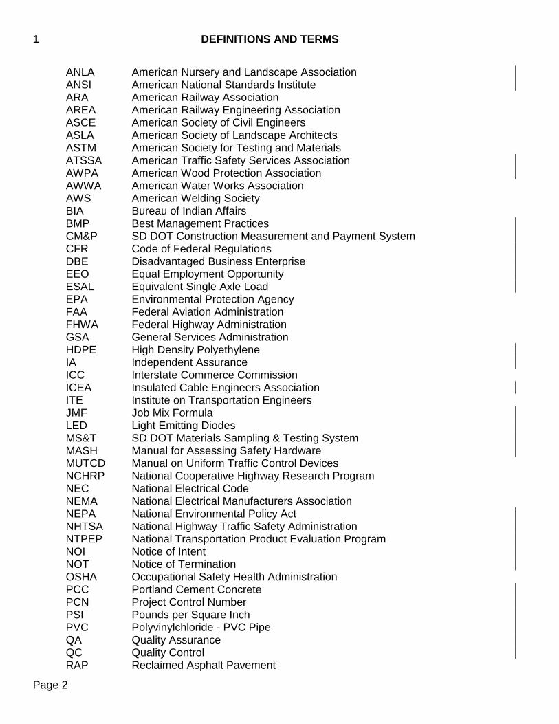
ANLA American Nursery and Landscape Association ANSI American National Standards Institute ARA American Railway Association AREA American Railway Engineering Association ASCE American Society of Civil Engineers ASLA American Society of Landscape Architects ASTM American Society for Testing and Materials ATSSA American Traffic Safety Services Association AWPA American Wood Protection Association AWWA American Water Works Association AWS American Welding Society BIA Bureau of Indian Affairs BMP Best Management Practices CM&P SD DOT Construction Measurement and Payment System CFR Code of Federal Regulations DBE Disadvantaged Business Enterprise EEO Equal Employment Opportunity ESAL Equivalent Single Axle Load EPA Environmental Protection Agency FAA Federal Aviation Administration FHWA Federal Highway Administration GSA General Services Administration HDPE High Density Polyethylene IA Independent Assurance ICC Interstate Commerce Commission ICEA Insulated Cable Engineers Association ITE Institute on Transportation Engineers JMF Job Mix Formula LED Light Emitting Diodes MS&T SD DOT Materials Sampling & Testing System MASH Manual for Assessing Safety Hardware MUTCD Manual on Uniform Traffic Control Devices NCHRP National Cooperative Highway Research Program NEC National Electrical Code NEMA National Electrical Manufacturers Association NEPA National Environmental Policy Act NHTSA National Highway Traffic Safety Administration NTPEP National Transportation Product Evaluation Program NOI Notice of Intent NOT Notice of Termination OSHA Occupational Safety Health Administration PCC Portland Cement Concrete PCN Project Control Number PSI Pounds per Square Inch PVC Polyvinylchloride - PVC Pipe QA Quality Assurance QC Quality Control RAP Reclaimed Asphalt Pavement

DEFINITIONS AND TERMS 1
Page 3
RCA Recycled Concrete Pavement/Aggregate RETMA Radio Electronic Television Manufacturers Association ROW Right-Of-Way SAE Society of Automotive Engineers International SDEBS South Dakota Department of Transportation Electronic Bid System SHPO State Historical Preservation Office SSPC The Society of Protective Coatings SWPPP Storm Water Pollution and Prevention Plan UL Underwriters Laboratory USACE United States Army Corps of Engineers USFS United States Forest Service USFWS United States Fish and Wildlife Service
1.5 DEFINITIONS ACT OF GOD - An unforeseeable act, event, or happening resulting from natural causes including, but not limited to, earthquake, tornado, or other cataclysmic phenomena. ADDENDUM - Changes to the bidding package issued by the contracting agency prior to the time of opening of bid proposals. ADVERTISEMENT - A public announcement inviting bid proposals for work to be performed or materials to be furnished. AREA ENGINEER - See Engineer. AWARD - The Department’s acceptance of a bid proposal. BASE COURSE - The layer or layers of specified select material placed on a subbase or a subgrade to support a surface course. BIDDER - An individual, partnership, firm, corporation, or an acceptable combination thereof, such as a joint venture, submitting a bid proposal for performance of prescribed work. BID PROPOSAL - The bidder’s offer, on the prescribed form, to furnish materials or to perform the work at the prices quoted. BID PROPOSAL GUARANTY - The security furnished with a bid proposal to guarantee the bidder will enter into the contract if the bid proposal is accepted. BID SCHEDULE - The list of bid items, together with estimated quantities, appearing in the bidding package. BRIDGE - A structure, including supports, erected over a depression or an obstruction, such as water, highway, or railway, said structure having a length measured along the center of roadway of more than 20 feet between undercopings of abutments or extreme
1 DEFINITIONS AND TERMS
Page 4
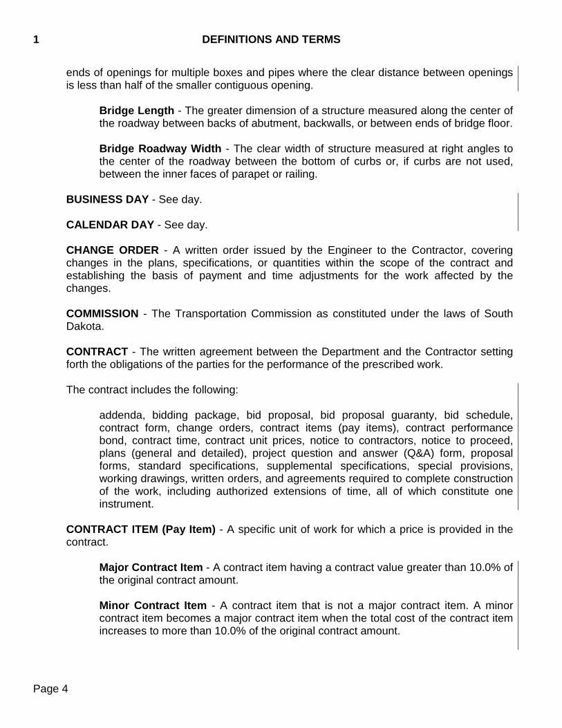
ends of openings for multiple boxes and pipes where the clear distance between openings is less than half of the smaller contiguous opening.
Bridge Length - The greater dimension of a structure measured along the center of the roadway between backs of abutment, backwalls, or between ends of bridge floor. Bridge Roadway Width - The clear width of structure measured at right angles to the center of the roadway between the bottom of curbs or, if curbs are not used, between the inner faces of parapet or railing.
BUSINESS DAY - See day. CALENDAR DAY - See day. CHANGE ORDER - A written order issued by the Engineer to the Contractor, covering changes in the plans, specifications, or quantities within the scope of the contract and establishing the basis of payment and time adjustments for the work affected by the changes. COMMISSION - The Transportation Commission as constituted under the laws of South Dakota. CONTRACT - The written agreement between the Department and the Contractor setting forth the obligations of the parties for the performance of the prescribed work. The contract includes the following:
addenda, bidding package, bid proposal, bid proposal guaranty, bid schedule, contract form, change orders, contract items (pay items), contract performance bond, contract time, contract unit prices, notice to contractors, notice to proceed, plans (general and detailed), project question and answer (Q&A) form, proposal forms, standard specifications, supplemental specifications, special provisions, working drawings, written orders, and agreements required to complete construction of the work, including authorized extensions of time, all of which constitute one instrument.
CONTRACT ITEM (Pay Item) - A specific unit of work for which a price is provided in the contract.
Major Contract Item - A contract item having a contract value greater than 10.0% of the original contract amount. Minor Contract Item - A contract item that is not a major contract item. A minor contract item becomes a major contract item when the total cost of the contract item increases to more than 10.0% of the original contract amount.
DEFINITIONS AND TERMS 1
Page 5
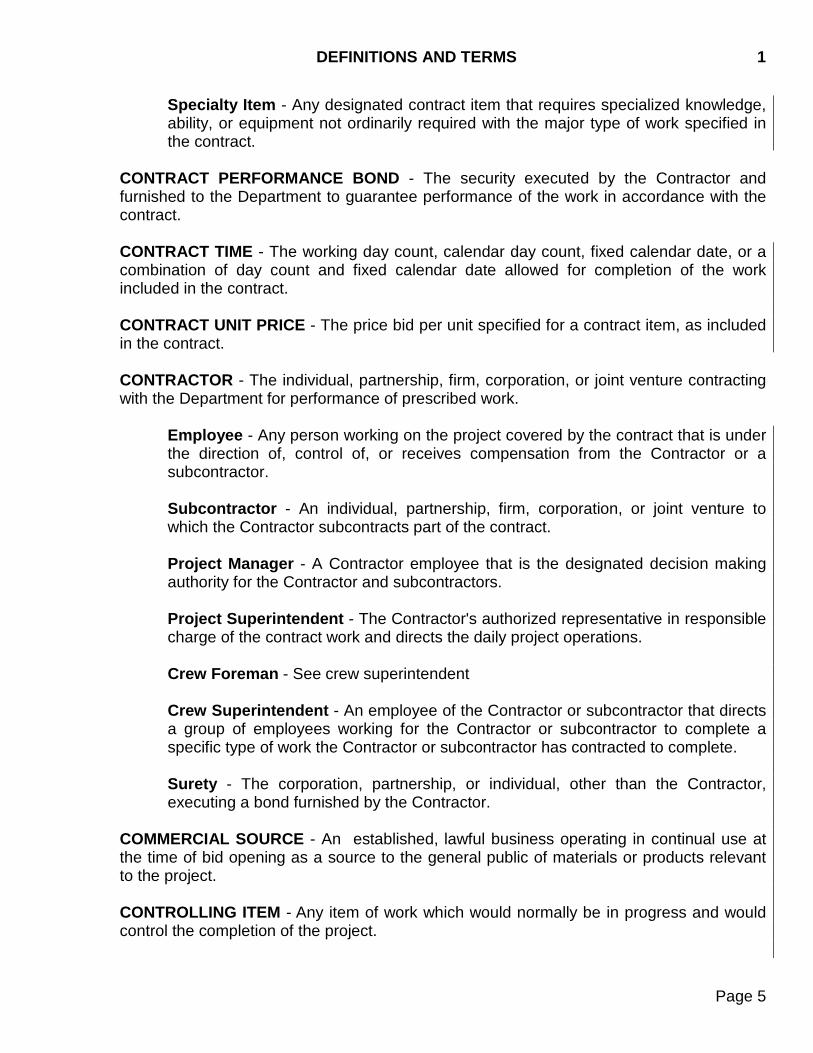
Specialty Item - Any designated contract item that requires specialized knowledge, ability, or equipment not ordinarily required with the major type of work specified in the contract.
CONTRACT PERFORMANCE BOND - The security executed by the Contractor and furnished to the Department to guarantee performance of the work in accordance with the contract. CONTRACT TIME - The working day count, calendar day count, fixed calendar date, or a combination of day count and fixed calendar date allowed for completion of the work included in the contract. CONTRACT UNIT PRICE - The price bid per unit specified for a contract item, as included in the contract. CONTRACTOR - The individual, partnership, firm, corporation, or joint venture contracting with the Department for performance of prescribed work.
Employee - Any person working on the project covered by the contract that is under the direction of, control of, or receives compensation from the Contractor or a subcontractor. Subcontractor - An individual, partnership, firm, corporation, or joint venture to which the Contractor subcontracts part of the contract. Project Manager - A Contractor employee that is the designated decision making authority for the Contractor and subcontractors. Project Superintendent - The Contractor's authorized representative in responsible charge of the contract work and directs the daily project operations. Crew Foreman - See crew superintendent Crew Superintendent - An employee of the Contractor or subcontractor that directs a group of employees working for the Contractor or subcontractor to complete a specific type of work the Contractor or subcontractor has contracted to complete. Surety - The corporation, partnership, or individual, other than the Contractor, executing a bond furnished by the Contractor.
COMMERCIAL SOURCE - An established, lawful business operating in continual use at the time of bid opening as a source to the general public of materials or products relevant to the project. CONTROLLING ITEM - Any item of work which would normally be in progress and would control the completion of the project.
1 DEFINITIONS AND TERMS
Page 6
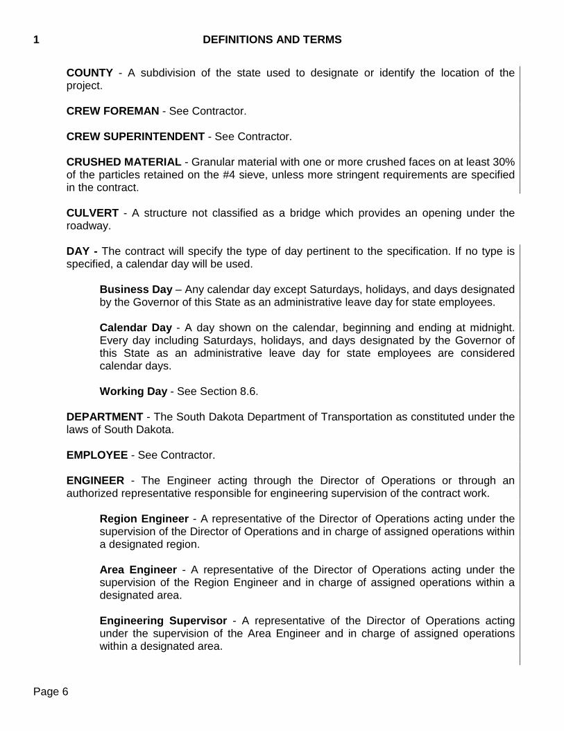
COUNTY - A subdivision of the state used to designate or identify the location of the project. CREW FOREMAN - See Contractor. CREW SUPERINTENDENT - See Contractor. CRUSHED MATERIAL - Granular material with one or more crushed faces on at least 30% of the particles retained on the #4 sieve, unless more stringent requirements are specified in the contract. CULVERT - A structure not classified as a bridge which provides an opening under the roadway. DAY - The contract will specify the type of day pertinent to the specification. If no type is specified, a calendar day will be used.
Business Day – Any calendar day except Saturdays, holidays, and days designated by the Governor of this State as an administrative leave day for state employees. Calendar Day - A day shown on the calendar, beginning and ending at midnight. Every day including Saturdays, holidays, and days designated by the Governor of this State as an administrative leave day for state employees are considered calendar days.
Working Day - See Section 8.6.
DEPARTMENT - The South Dakota Department of Transportation as constituted under the laws of South Dakota. EMPLOYEE - See Contractor. ENGINEER - The Engineer acting through the Director of Operations or through an authorized representative responsible for engineering supervision of the contract work.
Region Engineer - A representative of the Director of Operations acting under the supervision of the Director of Operations and in charge of assigned operations within a designated region. Area Engineer - A representative of the Director of Operations acting under the supervision of the Region Engineer and in charge of assigned operations within a designated area. Engineering Supervisor - A representative of the Director of Operations acting under the supervision of the Area Engineer and in charge of assigned operations within a designated area.
DEFINITIONS AND TERMS 1
Page 7
Project Engineer - A representative of the Director of Operations acting under the supervision of the Engineering Supervisor and responsible for engineering supervision of the contract work.
ENGINEERING SUPERVISOR - See Engineer. EQUIPMENT - Machinery, tools, implements, or apparatus, together with supplies for maintenance and upkeep, necessary for the construction and completion of the project. EROSION CONTROL - Those items necessary to the completed highway, which provide for the preservation of landscape materials and features. The rehabilitation and protection against erosion of areas disturbed by construction through seeding, sodding, mulching, and the placing of other ground covers. Such suitable planting and other improvements as may increase the effectiveness and enhance the appearance of the highway and adherence to water quality regulations. ESTIMATE OF QUANTITIES - Plan shown summary of the estimated quantities of work necessary to complete the project. EXTRA WORK - An item of work not provided for in the contract as awarded but found by the Engineer essential to the satisfactory completion of the contract within the contract’s intended scope. EXTRA WORK AUTHORIZATION - An agreement between the Department and the Contractor to perform extra work at an agreed price or on a force account basis. HOLIDAY - In the State of South Dakota the first day of every week, known as Sunday; the first day of January, commonly known as New Year's Day; the third Monday in January, commonly known as Martin Luther King Jr. Day; the third Monday in February, commonly known as Presidents Day; the last Monday of May, commonly known as Memorial Day; the fourth day of July, commonly known as Independence Day; the first Monday in September, commonly known as Labor Day; the second Monday in October, commonly known as Native American Day; the eleventh day of November, commonly known as Veterans' Day; the fourth Thursday in November, commonly known as Thanksgiving Day; and the twenty-fifth day of December, commonly known as Christmas Day; and every day designated by the President of the United States, or by the Governor of this State for a public fast, thanksgiving, or holiday will be observed as a legal holiday. If the first day of January, the fourth day of July, the eleventh day of November, or the twenty-fifth day of December falls upon a Sunday, the Monday following is a legal holiday and will be so observed. If any such day falls upon a Saturday, the preceding Friday is also a legal holiday and both Friday and Saturday will be so observed. INSPECTOR - The Engineer's authorized representative assigned to make detailed inspections of contract performance. LABORATORY - The Department’s testing laboratory or other testing laboratory which may be designated by the Engineer.
1 DEFINITIONS AND TERMS
Page 8
LETTING -
Letting Date - The time and date specified for the opening of bid proposal by the Notice to Contractors in the bidding package. Regional Letting - Department managed lettings conducted without the use of the SDEBS. SDEBS Letting - Department managed lettings conducted with the use of the SDEBS.
MAJOR CONTRACT ITEM - See contract item. MATERIALLY UNBALANCED BID - See unbalanced bid. MATERIALS - Substances specified for use in the construction of the project. MATHEMATICALLY UNBALANCED BID - See unbalanced bid. MINOR CONTRACT ITEM - See contract item. NOTICE OF AWARD - Written notice to the Contractor stating the Department’s acceptance of the bid proposal and the Department’s award of the contract. NOTICE TO CONTRACTORS - The advertisement for bid proposals for work or materials. The advertisement will indicate with reasonable accuracy the quantity and location of the work to be done or the character and estimated quantity of the material to be furnished and the time and place of the opening of bid proposals. NOTICE TO PROCEED - Written notice to the Contractor to begin with the contract work. PAVEMENT STRUCTURE - The combination of subbase, base course, and surface course placed on a subgrade to support and distribute the traffic load to the roadbed. PLAN QUANTITY - The quantity of a contract item shown on the bid item file and the plans. PLANS - The contract drawings showing the location, character, and dimensions of the prescribed work, including plan notes, layouts, profiles, cross sections, and contract documents. PREQUALIFICATION STATEMENT - The forms on which the Contractor will furnish required information as to the Contractor’s ability to perform and finance work. PROFILE GRADE - The trace of a vertical plane usually intersecting the top surface of the proposed subgrade surface, usually along the longitudinal centerline of the roadbed. Profile grade means either elevation or gradient of such trace according to the context.
DEFINITIONS AND TERMS 1
Page 9
PROJECT - The specific location, area, or section of the highway together with all appurtenances and construction to be performed under the contract. PROJECT CONTROL NUMBER (PCN) - A number generated by the Department for project tracking. Found on the cover sheet of the plans. PROJECT MANAGER - See Contractor. PROJECT SUPERINTENDENT - See Contractor.
PROJECT NUMBER - A number generated by the Department containing coded project data. Found on the cover sheet of the plans. PROJECT QUESTION AND ANSWER (Q&A) FORUM - An online medium for project specific questions and answers between prospective bidders and the Department. PROPOSAL FORM - The prescribed form on which the bidder’s offer is submitted. REGION ENGINEER - See Engineer. REGIONAL LETTING - See letting. RESPONSIVE BID PROPOSAL - A bid proposal that meets all requirements of the proposal package. RESPONSIBLE BIDDER - A bidder whose bid proposal meets all of the Department’s bidding requirements. RIGHT-OF-WAY - A general term denoting the property interest acquired for or devoted to a highway use. ROAD - A general term denoting a public way for purposes of vehicular travel, including the entire area within the right-of-way. ROADBED - The graded portion of a highway within top and side slopes, prepared as a foundation for the pavement structure and shoulders. ROADSIDE - A general term denoting the area adjoining the outer edge of the roadway. Extensive areas between the roadways of a divided highway may also be considered roadside. ROADWAY - The portion of a highway within limits of construction. SDEBS LETTING - See letting.
1 DEFINITIONS AND TERMS
Page 10
SHOULDER - The portion of the roadway contiguous with the traveled way for accommodation of stopped vehicles, emergency use, and lateral support of base and surface courses. SIDEWALK - That portion of the roadway primarily constructed for use by pedestrians. SPECIAL PROVISIONS - See specifications. SPECIFICATIONS - A general term applied to all directions, provisions, and requirements pertaining to performance of the work.
Special Provisions - Additions and revisions to the standard and supplemental specifications applicable to an individual project. Standard Specifications - A book of specifications approved for general applications and repetitive use. Supplemental Specifications - Approved additions and revisions to the standard specifications.
STANDARD SPECIFICATIONS - See specifications. STATE - The State of South Dakota acting through its authorized representative. STREET - A general term denoting a public way for purposes of vehicular travel, including the entire area within the right-of-way. STRUCTURES - Bridges, culverts, catch basins, drop inlets, retaining walls, cribbing, manholes, endwalls, buildings, sewers, service pipes, underdrains, foundation drains, and other features which may be encountered in the work and not otherwise classified. SUBBASE - The layer or layers of specified or selected material of designated thickness placed on a subgrade to support a base course or a surface course. SUBCONTRACTOR - See Contractor. SUBGRADE - The top surface of a roadbed upon which the pavement structure and shoulders, including curbs, are constructed. SUBSTRUCTURE - That part of a structure below the bearings of simple and continuous spans, skewback of arches, and top of the footings of rigid frames; including backwalls, wingwalls, and wing protection railings. For reinforced concrete slab bridges, that portion below the deck slab. SUPERINTENDENT - See Contractor. SUPERSTRUCTURE - The entire structure except the substructure.
DEFINITIONS AND TERMS 1
Page 11
SUPPLEMENTAL SPECIFICATIONS - See specifications. SURETY - See Contractor. SURFACE COURSE - One or more layers of a pavement structure designed to accommodate the traffic load, the top layer of which resists skidding, traffic abrasion, and the disintegrating effects of climate. The top layer sometimes called "Wearing Course". TOWNSHIP, CITY, TOWN, OR DISTRICT - A subdivision of the county used to designate or identify the location of the project. TRAFFIC - Vehicles, pedestrians, and other modes of transportation. UNBALANCED BID - A bid proposal that does not reflect the true cost of providing the material, equipment, and labor required to complete the contract item.
Materially Unbalanced Bid - A bid proposal in which there is reasonable doubt award to the bidder submitting the mathematically unbalanced bid will result in the lowest ultimate cost to the Department. Mathematically Unbalanced Bid - A bid proposal containing contract unit prices that do not reflect reasonable actual costs plus a reasonable proportionate share of the bidder’s anticipated profit, overhead costs, and other indirect costs, which the bidder anticipates for the performance of the contract items in question.
TRAVELED WAY - The portion of the roadway for the movement of vehicles, exclusive of shoulders. WORK - The providing of all labor, materials, equipment, and incidentals necessary to the successful completion of the project in accordance with the contract. WORKING DRAWINGS - Shop drawings, shop plans, erection plans, falsework plans, framework plans, bending diagrams for reinforcing steel, or supplementary plans or similar data which the Contractor is required to submit to the Engineer for review. WRITTEN ORDER - An order, issued in writing by the Engineer, of a contractual status requiring performance by the Contractor without negotiation of any sort.

1 DEFINITIONS AND TERMS
Page 12
THIS PAGE INTENTIONALLY LEFT BLANK

BIDDING REQUIREMENTS AND CONDITIONS 2
Page 13
2.1 PREQUALIFICATION OF BIDDERS - Prequalification on state highway construction contracts is required unless the amount being bid is less than $200,000. A prospective bidder must be prequalified prior to the time and date specified for bid opening. A prospective bidder may apply for prequalification by completing and executing a Contractor’s prequalification statement on a form approved by the Department. This application must be received by the Department's classification and rating committee at least 14 calendar days prior to the letting date. Once prequalified, the Department will issue a notice to the prospective bidder stating the prospective bidder’s approved work classification or work classifications, the prospective bidder’s overall bidding capacity, the prospective bidder’s per contract bidding capacity, and the prospective bidder’s expiration date for prequalification status. The complete prequalification requirements are contained in South Dakota Administrative Rule 70:07.
2.2 ELECTRONIC IDENTIFICATION - For contracts let using the South Dakota Electronic Bid System (SDEBS), a prospective bidder must register as a new user on the Department’s website to obtain a company identification and password. Certain bidding documents will only be available for download with proper company identification and password. Each company will receive one company identification and password. In addition to the company identification and password, a prospective bidder must obtain a bidder identification and password for each individual who will be authorized to submit a bid proposal on behalf of the company. To authorize an individual to submit a bid proposal on behalf of the company and obtain the bidder identification(s) and password(s), the company must complete a Bidding Authorization Form (available on the Department’s website), furnishing all required information and all appropriate notarized signatures, and submit the form to the Department no later than 48 hours prior to the bid opening. The individual receiving this bidder identification and password must be an authorized agent of the company having legal authority to do business for the company.
2.3 ISSUANCE OF BIDDING PACKAGE - The Department will issue bidding packages for
projects let using the Regional Letting process and the SDEBS Letting process.
For contracts let using the SDEBS Letting process, the Department will not place restrictions on who may download the bidding package, except certain documents will require a company identification described in Section 2.2. The bidder must verify the bidder’s prequalification status prior to bidding. The Department will verify bidder status in accordance with Section 3.1 prior to opening bids.
2.4 CONTENTS OF BIDDING PACKAGE - The bidding package consists of the proposal
booklet, plans, electronic design files, specifications, special provisions, supplemental specifications, addenda, project question and answer (Q&A) forum, and electronic bid files. The bidding package will state the location and description of the contemplated construction, show the estimate of the various quantities and type of work to be performed
2 BIDDING REQUIREMENTS AND CONDITIONS
Page 14
or materials to be furnished, and will have a schedule of items for which unit bid prices are invited. The bidding package will state the time in which the contract work must be completed, the time and date deadline for submitting the required bid proposals, and prequalification requirements.
A. Regional Lettings - Pages bound or attached to the bidding package by the
Department are considered a part of the bidding package and must not be detached or altered when the bid proposal is submitted, except the bidder may attach a substitute bid schedule as provided in Section 2.7. Plans, specifications, and other documents included by reference in the bidding package will be considered a part of the bidding package whether attached or not.
B. SDEBS Lettings - Prospective bidders must refer to the SDDOT website to acquire the
bidding package. The Department will open the project Q&A forum when the project is advertised for letting. Prospective bidders are responsible for periodically checking the project Q&A forum for new questions and answers. The Department will post questions and answers, but will provide no additional notification of the posting of questions and answers. Prospective bidders may post new questions to the project Q&A forum until 10:00 AM CT on the Friday prior to the letting, at which time prospective bidders will be locked from further posting. The Department may post new questions and answers to the project Q&A forum up until 10:00 AM CT on the Tuesday prior to the letting, at which time the project Q&A forum will be final and locked from all editing. In submitting a complete and final bid, a prospective bidder will be deemed to have accounted for any and all information posted to the final project Q&A forum regardless of when the prospective bidder submits a bid proposal.
2.5 INTERPRETATION OF QUANTITIES IN BIDDING PACKAGE - The quantities appearing
in the bidding package are estimates and are prepared for the comparison of bids. The Engineer will make payment to the Contractor for the actual quantities of work performed or materials furnished in accordance with the contract. The estimated quantities of work to be done and materials to be furnished may each be increased, decreased, or deleted as provided in these specifications.
2.6 EXAMINATION OF PLANS, SPECIFICATIONS, SPECIAL PROVISIONS, AND SITE OF
WORK - The bidder must examine the project site and the entire bidding package for the work contemplated. The bidder’s submission of a bid proposal will be considered conclusive evidence the bidder has investigated and is satisfied as to the conditions to be encountered; the character, quality, and quantities of work to be performed; and materials to be furnished, according to all contract documents.
Boring logs and other records of subsurface investigations are available for inspection by prospective bidders upon request. Prospective bidders must understand this information was obtained and is intended for Department design and estimating purposes only. The Department cannot guarantee the accuracy of this information. This information is made available so all prospective bidders have access to the same subsurface information
BIDDING REQUIREMENTS AND CONDITIONS 2
Page 15
available to the Department. The furnishing of this information is not intended as a substitute for the prospective bidder’s personal investigation, interpretation, and judgment. The Department will not be bound by any statement or representation made by any Department employee or agent prior to the execution of the contract, unless included in the bidding package. A prospective bidder must request any explanation regarding the meaning or interpretation of the bidding package in adequate time to allow a Department reply to reach all prospective bidders before submission of final bid proposals. A. Regional Lettings - For contracts let using the Regional Letting process, the bidder will
contact the office responsible for the letting. The Department may answer the request for explanation by issuing an addendum to all prospective bidders, as deemed appropriate by the Department in its sole discretion. The Department will make any addendum available to all prospective bidders before the time specified for opening of bid proposals.
The bidder will not take advantage of any apparent error, omission, or ambiguity in the bidding package. If the bidder discovers an error, omission, or ambiguity, the bidder will immediately notify the Department of the apparent error, omission, or ambiguity and its perceived consequences. The bidder will notify the Department by contacting the region office responsible for the letting. The Department may certify the error, omission, or ambiguity and may issue an addendum to all prospective bidders, as deemed appropriate by the Department in its sole discretion. The Department will make any addendum available to all prospective bidders before the time specified for opening of bid proposals.
B. SDEBS Lettings - For contracts let using the SDEBS, the bidder will contact the
Department by submitting a request for explanation to the project Q&A forum. If the deadline for submitting questions to the project Q&A forum has passed, the bidder will submit the request for explanation to the Department Bid Letting Office. The Department may answer the request for explanation on the project Q&A forum or issue an addendum to all prospective bidders, as deemed appropriate by the Department in its sole discretion. The Department will furnish any addendum to all prospective bidders by electronic addendum before the time specified for opening of bid proposals. The bidder will not take advantage of any apparent error, omission, or ambiguity in the bidding package. If the bidder discovers an error, omission, or ambiguity, the bidder will immediately notify the Department of the apparent error, omission, or ambiguity and its perceived consequences. The bidder will notify the Department by submitting a question to the project Q&A forum. If the deadline for submitting questions to the project Q&A forum has passed, the bidder will notify the Department Bid Letting Office. The Department may certify the error, omission, or ambiguity and may answer the question on the project Q&A forum or issue an addendum to all prospective bidders, as deemed appropriate by the Department in its sole discretion. The Department will furnish any addendum to all prospective bidders by electronic addendum before the time specified for opening of bid proposals.
2 BIDDING REQUIREMENTS AND CONDITIONS
Page 16
2.7 PREPARATION OF BID PROPOSAL - The Bidder will prepare the bid proposal as
described in the following: A. Regional Lettings - The Bidder will prepare the bid proposal on the forms furnished by
the Department. The Bidder will specify a unit price in numerals for each pay item for which a quantity is given, show the products of the respective unit prices and quantities written in numerals in the column provided for that purpose, and show the total amount of the bid proposal obtained by adding the amounts of all products. Numerals will be in ink or typed. The Department will refer to Section 3.2 in case of a discrepancy between the unit prices written in numerals for a pay item, the resultant product, and the total amount of the bid proposal. The bidder must specify a unit price, in numerals, for each bid item for which a quantity is given. A unit price cannot be “$0.00.” In case of a discrepancy between the line number, bid item description, or quantity shown in the bid proposal and the corresponding item shown in the plans, the bid item description and the quantity shown in the bid proposal will govern. When the bidding package contains an alternate bid item or group(s) of alternate bid items, the bidder must indicate a choice for each available item or group in accordance with the proposal for the particular item or group. The bidder's bid proposal must be signed by the individual, by one or more members of the partnership, by one or more members or officers of each firm representing a joint venture, by one or more officers of a corporation, or by an agent of the Contractor legally having a power of attorney. If signing pursuant to a power of attorney, the agent must be qualified and acceptable to the Department and a copy of the power of attorney must be attached to the bid proposal or previously filed with the Department. If the bid proposal is made by an individual, the individual's name and post office address must be shown; if by a partnership, the name and post office address of each partnership member must be shown; if by a joint venture, the name and post office address of each member or officer of the firms represented by the joint venture must be shown; if by a corporation, the name and business address of the corporation must be shown. The bidder may attach a substitute bid schedule in lieu of completing the original bid schedule, provided all of the provisions of this section are complied with. If the bidder uses a substitute bid schedule, the bidder will attach the substitute bid schedule to the original bid schedule. The bidder will include the following at the top of each page of the substitute bid schedule:
Letting Date Project Number PCN County Type of Work Bidder's Name and Address

BIDDING REQUIREMENTS AND CONDITIONS 2
Page 17
The substitute bid schedule will have the following column headings: line number, item description, estimated quantity, unit designation, unit bid price, and amount bid for each item. The substitute bid schedule will include total or gross sum bid below the last bid item. The substitute bid schedule will be in the legal name of the bidder and include the signature and title of an authorized representative, as required by this section. The original bid schedule does not need to be signed when using a substitute bid schedule unless the original bid schedule is used to authorize additional signatures. The bidder will also include the total or gross sum bid on the original bid schedule. In case of a discrepancy between the line number, bid item description, or quantity shown in the original bid schedule and that shown for any of these entries on the substitute bid schedule, the line number, bid item description, and the quantity shown in the original bid schedule will govern. The unit bid price shown for each line number on the substitute bid schedule will govern whether or not the product shown is correct. The substitute bid schedule page size and size of printed characters will be approximately the same as the original bid schedule. Solid lines for separating columns and line numbers need not be printed. At least one blank line or space will separate each line number. Columns may be arranged either vertically or horizontally on the substitute bid schedule. Pages must be arranged and numbered sequentially.
B. SDEBS Lettings - The bidder must prepare and submit a bid proposal using the latest version of the SDEBS. A prospective bidder may obtain the latest version of the SDEBS software from the Department website. The bidder must specify a unit price, in numerals, for each bid item for which a quantity is given. A unit price cannot be “$0.00.” When the bidding package contains an alternate bid item or group(s) of alternate bid items, the bidder must indicate a choice for each available group by entering unit prices for all bid items within the alternate chosen. The bidder must complete all required fields in the SDEBS. If the bidder does not completely fill out all required fields the Department may consider the bid irregular and reject the bid proposal in accordance with Section 3.2. For bidding purposes, in case of a discrepancy between the bid item description or quantity shown in the SDEBS and the corresponding item shown in the plans, the bid item description and the quantity shown in the SDEBS will govern.
2.8 BID PROPOSAL GUARANTY - The Bidder will secure a bid proposal guaranty as described in the following: A. Regional Lettings - No bid proposal will be considered unless accompanied by a
guaranty of the character and the amount indicated in the bid proposal form. B. SDEBS Lettings - The Department will not consider any bid proposal unless the bidder
has furnished the Department a guaranty in the amount of 5% of the total amount of the bid prior to opening of the bids. Satisfactory forms of proposal guaranties are certified
2 BIDDING REQUIREMENTS AND CONDITIONS
Page 18
checks, cashier’s checks, bank drafts issued upon a national or state bank, and bid bonds issued in accordance with South Dakota law. If the bidder uses an electronic bid bond, the bidder must submit the bid bond identification number with the bid proposal. Unless otherwise specified in the bidding package, the proposal guaranty must be made payable at sight to the “South Dakota Department of Transportation.”
2.9 BIDDER SUBMITTED BID PROPOSAL LIMITATIONS - A Bidder may submit a written
statement providing limitation of work for a single bid letting date. The bidder must submit the written bid proposal limitation statement to the Department prior to the time and date set for opening the bid proposals. A bidder may submit a written statement providing limitation of work for bid proposals submitted in subsequent bid proposal openings provided the Department has not awarded contracts from an earlier bid letting date by the time of the latter bid letting date; and, the bidder submits the written bid proposal limitation statement to the Department prior to the time and date set for opening bid proposals of the latter bid letting date. A written bid proposal limitation statement must include the following information: A. Identification of the bidder’s company name and name and title of the employee
submitting the bid proposal limitation statement;
B. Identification of the bid proposal opening date or dates and the contracts for which the limitations apply; and,
C. A statement of the total dollar volume of work or number of contracts acceptable to the bidder.
If a bidder submits a bid proposal limitation statement and becomes the apparent low bidder on multiple contracts exceeding the limitations the bidder has set forth, the Department will determine, in its sole discretion, which contract or contracts will be awarded to the bidder within the limitations set by the bidder.
2.10 SUBMISSION OF BID PROPOSAL - The bidder will submit the bid proposal as described
in the following:
A. Regional Lettings - The bidder will place the bid proposal in a sealed envelope plainly marked to indicate its contents. When sent by mail, the bidder will address the sealed proposal to the Department in care of the official responsible for the letting. The bidder will file the bid proposal prior to the time and date and at the place specified by the Notice to Contractors. The Department will not accept any bid proposal received after the time and date specified for opening of bid proposals and will return any late bid proposal to the bidder unopened.
B. SDEBS Lettings - A bidder must submit a bid proposal electronically using the SDEBS
to the Department’s secure bid submission site prior to the time and date specified by the Notice to Contractors in the bidding package. The Department will not accept any bid proposal received after the time specified for opening of bid proposals.
BIDDING REQUIREMENTS AND CONDITIONS 2
Page 19
2.11 WITHDRAWAL OR REVISION OF BID PROPOSAL PRIOR TO LETTING - A bidder may
withdraw or revise a bid proposal after it has been submitted, if the withdrawal is made before the time set for opening bid proposals and according to the following: A. Regional Lettings - A bidder may withdraw or revise a bid proposal after it has been
deposited with the Department, if the request for withdrawal or revision is received by the Department in writing before the time set for opening bid proposals.
B. SDEBS Lettings - A bidder may withdraw or revise and resubmit a bid proposal any time prior to the time and date set for opening the proposals. The Department will consider only the last bid proposal submitted as a valid bid proposal for the letting item. A bidder may withdraw or revise and resubmit a bid proposal only through the Department’s secure bid proposal submission site.
2.12 COMBINATION BIDDING PACKAGES – When required in the bidding package, the
Department will require a bidder to submit a bid proposal for multiple bidding packages in combination. The Department will consider award of the contracts based on the total of the combination of the bid proposals. The Department will not consider a combination bid proposal, other than as specified. The Department will write a separate contract for each project included in the combination.
2.13 PUBLIC OPENING OF BID PROPOSALS - The Department will open and read bid
proposals according to the following: A. Regional Lettings - The Department will open and read bid proposals publicly at the
time, date, and place indicated by the Notice to Contractors.
B. SDEBS Lettings - The Department will open and read bid proposals at the time and date set for opening the bid proposals. The Department will check all bid proposals for qualifications and will post the results on the Department’s website.

2 BIDDING REQUIREMENTS AND CONDITIONS
Page 20
THIS PAGE INTENTIONALLY LEFT BLANK
AWARD AND EXECUTION OF CONTRACT 3
Page 21
3.1 CONSIDERATION OF BID PROPOSALS - At the time of opening bid proposals, the Department will verify the bidder is prequalified for the specified work type and the bidder’s bidding capacity at that time is sufficient to handle the work for which the bidder submitted a bid proposal. The Department reserves the right to refuse to accept a bid proposal for any of the following reasons: A. Lack of competency or adequate machinery, plant, or other equipment, as shown by the
Contractor’s Prequalification Statement;
B. Uncompleted work which the Department determines, in its sole discretion, may hinder or prevent the prompt completion of additional work;
C. Failure to pay or satisfactorily settle any legal obligation due for labor or material on any contract at the time of issuance of proposals;
D. Failure to comply with the Department’s prequalification regulations;
E. Default under any previous contract or contracts;
F. Debarment by the Department or the federal government;
G. Disqualification by the Department. The following reasons will be considered sufficient for disqualifying a bidder and rejecting the bid proposal or bid proposals:
1. Submittal of more than one bid proposal for the same work from an individual, firm,
or corporation under the same or different name; or,
2. Evidence of collusion among bidders. A participant in collusion will not receive recognition as a bidder for future work with the Department until reinstated as a qualified bidder;
H. Lack of overall bidding capacity as established by the Contractor’s prequalification
statement, considering the uncompleted work currently under contract;
I. Lack of per contract bidding capacity as established by the Contractor’s prequalification statement; or,
J. Unsatisfactory performance on previous work or any current contract or contracts
consisting of, but not limited to:
1. Noncompliance with contract specifications, contract requirements, or Engineer's directives;
2. Failure to complete work on time;
3. Instances of substantial corrective work prior to acceptance;
4. Instances of completed work that requires acceptance at reduced pay;
3 AWARD AND EXECUTION OF CONTRACT
Page 22
5. Production of work or materials not meeting required specifications, and when
applicable, requiring price reductions or corrective work;
6. Failure to provide adequate safety measures or appropriate traffic control that endangers the safety of the work force and public;
7. Questionable moral integrity as determined by the Attorney General of the State, or
the Department; or,
8. Failure to reimburse the State for monies owed on any previously awarded contract including any contract where the prospective bidder is a party to a joint venture and the joint venture has failed to reimburse the State for monies owed.
After opening, the Department will compare the bid proposals on the basis of the summation of the products of the quantities shown in the bid proposal by the unit bid prices. The Department will make results of such comparisons available to the public. In the event of a discrepancy between unit bid prices and extensions, the unit bid price will govern.
The Department reserves the right to reject any bid proposal, the right to waive technicalities, and the right to reject all bid proposals and advertise for new bid proposals, if in the sole judgment of the Department the rejection or waiver will promote the best interest of the Department.
3.2 IRREGULAR BID PROPOSALS - The Department will consider a bid proposal irregular
and may reject the bid proposal for any of the following reasons:
A. The bid proposal is incomplete, or is submitted on a form other than the Department’s latest version of the SDEBS or the form furnished by the Department, the form is altered, or part thereof is detached or incomplete;
B. The bid proposal contains unauthorized additions, conditional or alternate bids, or other
irregularities, which may tend to make the bid proposal incomplete, indefinite, or ambiguous as to its meaning;
C. The bid proposal contains provisions reserving the right to accept or reject an award or
to enter into a contract pursuant to an award. (This is not intended to exclude a bid proposal limiting the maximum gross amount of awards acceptable to a bidder at one bid letting. The Department will select awards in its sole discretion.);
D. The bid proposal does not contain a unit price in numerals for each pay item listed,
except in the case of authorized alternate pay items or groups;
E. The Department determines, in its sole discretion, that any of the unit bid prices are significantly unbalanced to the potential detriment of the Department;
AWARD AND EXECUTION OF CONTRACT 3
Page 23
F. For Regional lettings, in the case of a discrepancy between the unit bid price and the price extension, the unit bid price will govern. If the intended unit bid price cannot be determined, the bid proposal will be voided as per Section 3.2 B;
G. For SDEBS lettings, the bid proposal is signed with an invalid bidder identification; H. For SDEBS lettings, confirmation of receipt of all addenda issued by the Department is
not included in the bid proposal; or, I. For SDEBS lettings, incorporation of the addendum bid item file is not included in the
bid proposal file. 3.3 DISMISSAL OF BID PROPOSAL - After the opening of the bid proposals but prior to the
award of a contract, a bidder may submit a written request to have the bidder’s bid proposal dismissed if an error was made in the preparation of the bid proposal. The bidder must include supporting documentation justifying the request. The request must include a notarized affidavit or declaration signed under penalty of perjury which clearly sets forth the specific error or errors and certifies the bid documentation submitted is the only information used in the preparation of the bid proposal. The Department will review the request prior to making a determination of the request. If the Department determines, in its sole discretion, to grant the request to dismiss the bid proposal, the Department will retain the bidder’s bid proposal guaranty unless the bidder satisfies all of the following conditions: A. The bidder immediately notifies the Department as soon as the error is observed and no
later than 2 business days after the bid letting date;
B. The error is of a mechanical, clerical, or mathematical nature and not one of bad judgment, careless inspection of the work site, or in reading the plans and specifications. The bidder must be able to produce bid preparation documentation clearly setting forth how the clerical error occurred;
C. The bidder submits the formal request and required documentation within 1 business
day of notifying the Department of the error; and, D. The scope of the mistake is significant in nature as determined by the Department, in its
sole discretion. The Department will notify the bidder of the decision to either grant the request for dismissal of the bid proposal without forfeiture of the bid proposal guaranty to the Department, or to allow dismissal of the bid proposal with forfeiture of the bid proposal guaranty to the Department. The bidder will then have 1 business day to respond in writing to either confirm acceptance of the Department’s decision which will result in an irregular bid proposal, or withdraw their request to dismiss their bid proposal which will result in a responsive bid proposal for award of contract consideration. If the bidder does not respond within 1 business day the Department’s decision will stand.
3.4 AWARD OF CONTRACT - The Department will award a contract to the lowest competent and responsible bidder whose bid proposal complies with the requirements prescribed,
3 AWARD AND EXECUTION OF CONTRACT
Page 24
within 30 calendar days after the opening of bid proposals. The Department will notify the successful bidder that the bid has been accepted and the contract awarded.
The Department and the successful bidder may extend the contract award date by mutual agreement.
3.5 CANCELLATION OF AWARD - The Department reserves the right to cancel the award of a contract before the execution of said contract without liability against the Department.
3.6 BID PROPOSAL GUARANTY - The Department will retain the bid proposal guaranties of
the two lowest responsible and competent bidders. The Department will release the remaining bid proposal guaranties following opening and checking of bid proposals. The Department will release the bid proposal guaranties of the two low bidders when the contract has been executed.
3.7 REQUIREMENT OF CONTRACT PERFORMANCE BOND - At the time of the execution of
the contract, the successful bidder will furnish a contract performance bond or bonds in a sum equal to the amount of the contract, in a form acceptable to the Department. The contract performance bond will remain in effect for not less than one year after the date of the Region Engineers letter of Final Acceptance.
If the Contractor’s bonding company becomes insolvent or is declared bankrupt, the Department will require the Contractor to furnish a new contract performance bond.
3.8 EXECUTION AND APPROVAL OF CONTRACT - The successful bidder will sign and return the contract, together with the contract performance bond, within 20 calendar days after the date of the Notice of Award. The Department and the successful bidder may extend the contract return by mutual agreement. If the Department does not execute the contract within 15 calendar days following the receipt of the signed contract and related documents from the bidder, the bidder may withdraw the bid without penalty. A contract will not be considered in effect until it has been executed by all parties to the contract.
3.9 FAILURE TO EXECUTE CONTRACT - If the successful bidder does not execute and return
the contract and file acceptable bond within 20 calendar days after bidder’s receipt of the Notice of Award the Department may cancel the award and the bid proposal guaranty will be forfeited and become the property of the Department, as liquidated damages. The Department may then award a contract to the next lowest responsible bidder, or re-advertise the work.
3.10 MATERIAL GUARANTY - The successful bidder will furnish a complete statement of the origin, composition, and manufacture of materials to be used in the construction of the work, together with samples. Samples will be tested and inspected for conformance with the contract provisions.

SCOPE OF WORK 4
Page 25
4.1 INTENT OF CONTRACT - The intent of the contract is to provide for the construction and completion in detail of the work described. The Contractor will furnish labor, materials, equipment, tools, transportation, and supplies required to complete the work in accordance with the plans, specifications, and terms of the contract.
4.2 DIFFERING SITE CONDITIONS – During the progress of the work, if subsurface or latent
physical conditions are encountered at the site differing materially from those indicated in the contract or if unknown physical conditions of an unusual nature, differing materially from those ordinarily encountered and generally recognized as inherent in the work provided for in the contract, are encountered at the site, the party discovering such conditions will promptly notify the other party in writing of the specific differing conditions before the site is disturbed and before the affected work is performed. Upon written notification, the Engineer will investigate the conditions, and if it is determined that the conditions materially differ and cause an increase or decrease in the cost or time required for the performance of any work under the contract, an adjustment, excluding anticipated profits, will be made and the contract modified in writing accordingly. The Engineer will notify the Contractor of the determination whether or not an adjustment of the contract is warranted. No contract adjustment which results in a benefit to the Contractor will be allowed unless the Contractor has provided the required written notice. No contract adjustment will be allowed on work not affected by the changed conditions.
4.3 SIGNIFICANT CHANGES IN THE CHARACTER OF WORK - The Engineer reserves the right to make, in writing, at any time during the work, such changes in quantities and such alterations in the work as are necessary to satisfactorily complete the project. Such changes in quantities and alterations will not invalidate the contract or release the contract performance bond, and the Contractor agrees to perform the work as altered, as if the work had been part of the original contract. If the alterations or changes in quantities significantly change the character of the work under the contract, whether such alterations or changes are in themselves significant changes to the character of the work or by affecting other work cause such other work to become significantly different in character, an adjustment, excluding anticipated profit, will be made to the contract. The basis for the adjustment must be agreed upon prior to the performance of the work. If a basis cannot be agreed upon, then an adjustment will be made either for or against the Contractor in such amount as the Engineer may determine to be fair and equitable. If the alterations or changes in quantities do not significantly change the character of the work to be performed under the contract, the altered work will be paid for as provided elsewhere in the contract. The term “significant change” shall be construed to apply only to the following circumstances:

4 SCOPE OF WORK
Page 26
A. When the character of the work as altered differs materially in kind or nature from that involved or included in the original proposed construction; or
B. When a major item of work, as defined in Section 1.5, is increased in excess of 125% or
decreased below 75% of the original contract quantity. Any allowance for an increase in quantity shall apply only to that portion in excess of 125% of original contract item quantity, or in case of a decrease below 75%, to the actual amount of work performed.
When an adjustment to the unit price is made due to a decrease in the contract quantity to below 75% of the original contract quantity, the total payment made will not exceed the amount which would have been paid for 75% of the original contract quantity. If the Contractor believes an alteration in the work is a significant change that necessitates a contract revision, the Contractor must request a contract revision for the significant change in work in writing to the Engineer. The Department will pay the Contractor for work occasioned by alterations in plans in accordance with the provisions set forth under Section 9.4. If the altered work is of sufficient magnitude that additional time to complete the project is warranted, the Department will make time adjustments in accordance with the provisions of Section 8.7.
Items and prices set forth in the Special Provision for Price Schedule for Miscellaneous Items and the bidding package are predetermined by the Department and will not be subject to negotiation due to alterations in the plans or quantity changes.
4.4 EXTRA WORK - The Contractor will perform authorized work for which there is no price
included in the contract whenever necessary or desirable in order to complete the work as contemplated. The Contractor will perform this extra work in accordance with the specifications and as directed, and be paid for as provided under Section 9.5.
4.5 MAINTENANCE OF TRAFFIC - Unless otherwise provided, the Contractor will keep the
road open to traffic in accordance with the traffic control plans. The Contractor will keep the portion of the project used by public traffic in a condition that will adequately and safely accommodate traffic. Accommodation of traffic will include, but not be limited to, providing a roadway in a passable condition, providing flaggers in areas where the operation of construction equipment interferes with the movement of traffic, sweeping, and providing and maintaining in a safe condition pedestrian routes, temporary approaches or crossings, and intersections with trails, roads, streets, businesses, parking lots, residences, garages, and farms. While sweeping in curb and gutter sections or in rural sections where a finished and maintained lawn extends to the edge of the shoulder, the Contractor will use a pickup broom having an integral self-contained storage. The pickup broom must be a minimum of 6 feet wide. While sweeping in curb and gutter sections the pickup must have working gutter brooms. The Contractor will not be required to provide snow removal.
The Contractor will bear the expense of maintaining traffic over the project undergoing improvement and constructing and maintaining approaches, crossings, intersections, and
SCOPE OF WORK 4
Page 27
other features as may be necessary, without direct compensation, except as provided below: A. Traffic Diversions - Traffic diversions will be designated in the Contract. Right-of-way
for traffic diversions will be furnished by the Department.
Construction, maintenance, and removal of traffic diversions will be as directed by the Engineer.
Materials, other than temporary drainage structures, required to construct and maintain traffic diversions will be paid for at their respective contract unit prices.
The cost of labor, equipment, and incidentals required to satisfactorily maintain traffic diversions and provide temporary drainage structures will be incidental to the contract lump sum price for maintenance of traffic diversions.
The cost of labor, equipment, and incidentals necessary to satisfactorily remove traffic diversions and dispose of materials will be incidental to the contract lump sum price for remove traffic diversion(s).
B. Maintenance of Traffic During Suspension of Work:
1. Prior to written suspension due to unfavorable weather or conditions not the fault of the Contractor, the Contractor will prepare the project as directed by the Engineer to provide for the accommodation of traffic during the anticipated period of suspension. During the suspension and until an order for resumption of construction operations is issued, the maintenance of the project for traffic, to the extent specified in writing by the Engineer, will be by and at the expense of the Department. When the order for the resumption of work is issued, the Contractor will be responsible for the maintenance of traffic and will replace or repair work or materials lost or damaged during the period of suspension, remove any work or materials for maintenance, and complete the project in every respect as though the project’s prosecution had been continuous and without interference. The Department will pay for additional work made necessary by such suspensions, for reasons beyond the control of the Contractor, at contract prices or by extra work.
2. The Contractor will maintain, replace, or repair any work or material lost or damaged, without cost to the Department, during periods not covered by a written suspension order and when the work is suspended for the Contractor's failure to comply with the provisions of the Contract.
4.6 RIGHTS IN AND USE OF MATERIALS FOUND ON THE WORK - The Engineer may
authorize the Contractor’s use of materials found in the excavation that are suitable for completing bid items other than excavation. The Department will pay the Contractor for the excavation of such materials at the corresponding contract unit price and for the pay item for which the excavated material is used. The Contractor will replace all excavation material removed with acceptable material, at the Contractor's expense. Charge for the materials so used will not be made against the Contractor. The Contractor will not excavate or remove
4 SCOPE OF WORK
Page 28
any material from within the highway right-of-way which is not within the grading limits, without the Engineer’s written authorization.
Unless otherwise provided, the Contractor may temporarily use the material from an existing structure in the erection of the new structure. The Contractor will not modify such material, without the Engineer’s approval.
4.7 FINAL CLEANING UP - Before the Area Office makes Acceptance of Field Work, and
unless otherwise approved by the Engineer, the Contractor will clear the highway and areas occupied by the Contractor in connection with the work of rubbish, excess materials, temporary structures, and equipment; and leave the work in an acceptable condition.
4.8 VALUE ENGINEERING INCENTIVE
A. General: Value engineering incentive applies to those cost reduction proposals initiated and developed by the Contractor for changing the drawings, designs, specifications, or other requirements of the contract. The value engineering incentive does not apply to a cost reduction proposal unless the Contractor identifies the value engineering incentive at the time of submission to the Department.
The cost reduction proposals contemplated are those that:
1. Would require a change order to this contract.
2. Would result in savings to the Department by providing less costly items or methods
than those specified in the contract without impairing any essential functions and characteristics such as service life, reliability, economy of operation, ease of maintenance, and necessary standardized features.
B. The Department will process cost reduction proposals in the same manner as
prescribed for any proposal which would require a change order. At a minimum the Contractor must submit the following information with each proposal:
1. A statement that the cost reduction proposal is submitted for consideration as a
value engineering incentive.
2. A description of the cost reduction proposal.
3. An itemization of the requirements of the contract which would require a change and a recommendation of how to make each change.
4. An estimate of the reduction in performance costs that will result from adoption of
the cost reduction proposal.
5. A prediction of any effects the proposed change would have on other costs to the Department.
SCOPE OF WORK 4
Page 29
6. A time schedule, or date, within which the change order must be issued to obtain the maximum cost reduction during the remainder of the contract and the reason for this time schedule.
7. The dates of any previous submission of the cost reduction proposals, including
contract numbers and the actions of the Department.
8. A statement as to the effect the cost reduction proposal would have on the time for completion of the project.
C. The Department will not be liable for delay in acting upon a cost reduction proposal
submitted. The Engineer’s decision as to the acceptance of any such cost reduction proposal will be final and will not be subject to Section 5.17. The Engineer may accept, in whole or in part, cost reduction proposals submitted by issuing a change order that incorporates the accepted elements of the proposal into the contract by changes to quantities of existing contract items, addition of new contract items at agreed upon unit prices or lump sums, changes to contract plans and specifications, or any combination as appropriate.
If the Engineer accepts a cost reduction proposal, the Engineer will make an equitable adjustment in the contract price and change other affected provisions of this contract in accordance with this Specification and other applicable provisions in this contract. The Engineer will establish the equitable adjustment based on the Engineer’s determination of the effect of the Contractor's cost reduction proposal. When the cost of performance is decreased as the result of the change, the Engineer will reduce the contract price by the following amount: 50% of the difference between the total estimated decreases in the cost of performance and the total estimated increases in the cost of performance reasonably anticipated as a result of application of the cost reduction proposal. If the contract changes associated with the value engineering proposal results in an increase in the cost of performance, this specification will not apply and the increase will be determined in accordance with Section 9.4.
D. The Engineer will not consider substitution of one bid item for another bid item resulting
in a decrease in the contract amount as a saving under value engineering incentive. When the change involves the increase of one bid item and the decrease of another bid item, the change order will be made in conformance with Section 9.4.
E. The Contractor may restrict the Department's right to use or disclose the information
submitted with a cost reduction proposal for other purposes. Such restrictions must be in writing and be submitted with the cost reduction proposal.
F. If the Engineer accepts the cost reduction proposal, the Contractor’s restriction will be
void and the Department may use, duplicate, or disclose in whole or in part data necessary to utilize the cost reduction proposal.

4 SCOPE OF WORK
Page 30
THIS PAGE INTENTIONALLY LEFT BLANK

CONTROL OF WORK 5
Page 31
5.1 AUTHORITY OF THE ENGINEER - The Contractor will perform the work to the satisfaction of the Engineer. The Engineer will decide questions which may arise, including but not limited to the following: the quality and acceptability of materials furnished, work performed, and rate of progress of the work; all questions which may arise as to the interpretation of the plans and specifications; all questions as to the Contractor’s acceptable fulfillment of the contract; and disputes between Contractors where it effects the progress of the work. The Engineer's decision will be final. The Engineer will have the authority to suspend the work wholly or in part, by written suspension order for the following reasons: A. The Contractor does not carry out contract requirements;
B. The Contractor does not carry out orders from the Engineer; C. Periods of unsuitable weather; D. Conditions considered unsuitable for the prosecution of the work; E. Other condition or reason determined by the Department to be in the public interest; or, F. Other reasons mutually agreed on by the Engineer and the Contractor.
5.2 PLANS AND WORKING DRAWINGS - Plans will show details of structures, lines, grades, typical cross sections of the roadway, location, and design of structures and a summary of items appearing on the proposal. The Contractor will have 1 set of plans, specifications, and other contract documents available at the work site.
The Contractor will supplement plans with working drawings, consisting of detailed plans, as required in the plans or specifications to control the work. These working drawings will include stress sheets, shop plans, erection plans, falsework plans, bending diagrams for reinforcing steel, erosion control plans, or other supplementary plans or data. Working drawings must be reviewed by the Engineer. The Engineer’s review will not relieve the Contractor of responsibility under the contract for completion of the work.
5.3 CONFORMITY WITH PLANS AND SPECIFICATIONS - Work performed and materials furnished will conform to the lines, grades, cross sections, dimensions, and material requirements, including tolerances, shown on the plans, specifications, and other contract documents. If the Engineer determines the materials furnished, work performed, or the finished product is not within strict conformity with the plans and specifications, the Contractor will remove and replace or correct the work or materials at the Contractor’s expense. If the Engineer determines the materials furnished, work performed, or the finished product
5 CONTROL OF WORK
Page 32
is not within strict conformity with the plans and specifications but is within reasonable conformity, the Engineer may accept the materials furnished and work performed and allow the finished product to remain in place. If the Engineer allows reasonably conforming materials furnished, work performed, or the finished product to remain in place, the Engineer will document the basis of acceptance by contract modification. This documentation will provide for an adjustment in the contract price, determined in the Department’s sole discretion. If the Engineer determines the materials furnished, work performed, or the finished product is not in reasonably close conformity with the plans and specifications, resulting in an inferior or unsatisfactory product, the Contractor will remove and replace or correct the work or materials at the Contractor’s expense.
If the Engineer determines the materials furnished, work performed, or the finished product is not in conformity with the plans and specifications and may have an impact on traffic or public safety, the Contractor will immediately remove and replace or correct the work or materials at the Contractor’s expense, and any work or materials allowed to remain in place may be subject to price adjustment.
5.4 COORDINATION OF CONTRACT DOCUMENTS - The contents of the bidding package
are essential parts of the contract. A requirement occurring in one is as binding as though occurring in all. The contents of the bidding package are intended to be complementary and to describe and provide for a complete work.
If any discrepancy exists, the governing ranking is:
1. Addenda 2. Project Q&A forum 3. Special provisions 4. Plans 5. Supplemental specifications 6. Standard specifications 7. Electronic design files
Addenda will govern over the project Q&A forum unless a Department response in the project Q&A forum specifically addresses an addendum issued by the Department. In case of a discrepancy between questions on the project Q&A forum regarding the same topic, the most recent question and answer will govern over previous questions and answers. Questions will be numbered on the project Q&A forum in order of date and time posted. In addition, plans shown dimensions will govern over scaled dimensions. The Contractor will not take advantage of any apparent error, omission, or ambiguity in the contract. If the Contractor discovers an error, omission, or ambiguity, the Contractor will immediately notify the Engineer of the apparent error, omission, or ambiguity and its perceived consequences. The Engineer will make corrections and interpretations as
CONTROL OF WORK 5
Page 33
necessary to fulfill the intent of the contract. 5.5 COOPERATION BY CONTRACTOR - The Department will supply the Contractor with a
minimum of 2 sets of plans and related contract documents, 1 of which the Contractor will have available on the project.
The Contractor will give the work the constant attention necessary to facilitate the progress, and will cooperate with the Engineer, inspectors, and other contractors.
The Contractor will have on the project at all times, as the Contractor’s agent, a competent superintendent capable of reading and understanding the plans and specifications and experienced in and capable of accomplishing the type of work being performed. The Contractor will have this superintendent on the project at all times regardless of the amount of work subcontracted.
5.6 COOPERATION WITH UTILITIES - The Department will notify utility companies, pipe line
owners, and other parties affected, and have adjustments of the public or private utility fixtures, pipe lines, and other appurtenances within or adjacent to the limits of construction made as soon as practicable.
Utility appurtenances within the limits of the proposed construction which are to be relocated or adjusted are to be moved by the owner at the owner’s expense unless otherwise provided in the contract.
The Contractor will be deemed to have considered in the Contractor’s bid the permanent and temporary utility appurtenances in their present or relocated positions as specified in the contract. The Department will not allow the Contractor additional compensation for any delay, inconvenience, or damage sustained due to interference from the utility appurtenances or relocation.
Where it is reasonably foreseeable the Contractor’s operations will result in considerable damage, expense, loss, or inconvenience to adjacent property, including, but not limited to railway, telecommunications, electric, water, sewer, petroleum products, and private property, the Contractor will not commence operations until the Contractor has made the arrangements necessary to protect these other interests.
The Contractor will cooperate with utility owners in removing and rearranging underground or overhead utility lines or facilities to minimize interruption of service and duplication of work by utility owners.
If utility service is interrupted, the Contractor’s cooperation will be continuous until the service is restored. The Contractor will not commence work around a fire hydrant until provisions for continued service have been approved by the local fire authority.
Contractors are required to comply with South Dakota Codified Law (SDCL) 49-7A and Administrative Rule Article 20:25 addressing South Dakota One-Call notification before excavation activities.
5 CONTROL OF WORK
Page 34
If an excavation is made in a time of an emergency, the Contractor will take all reasonable precautions to protect the underground utilities. In emergencies, the Contractor will notify the South Dakota One-Call notification center as required above as soon as practical. In accordance with Administrative Rule Article 20:25, the utility will as soon as possible but not longer than 2 hours from the notification time during the business day and not longer than 4 hours from the notification time outside of the business day or by the start time on the ticket, whichever is later provide all reasonably available practical information to the Contractor. An emergency is defined as an occurrence which demands immediate action to prevent significant environmental damage or loss of life, health, property, or essential public services including the re-erecting of critically needed traffic control signs or devices.
If an underground utility is damaged, dislocated, or disturbed, the Contractor will notify the owner of the utility, or if unknown, the South Dakota One-Call notification center. The Contractor is prohibited from concealing, attempting to conceal, or making repairs to the utility unless authorized by the utility owner.
If the Contractor is unable to locate the underground utility or discovers that the owner has incorrectly located the facility, the Contractor will promptly notify the owner or the South Dakota One-Call notification center.
5.7 COOPERATION BETWEEN CONTRACTORS - The Department reserves the right to
contract and perform additional work within the limits of or adjacent to the work covered by the contract.
When separate contracts are let within the limits of or adjacent to the project, the Contractor will conduct work without interfering or hindering the progress or completion of the work by other contractors. Contractors working within the limits or adjacent to the project will cooperate with each other as directed. The Contractor will arrange work and will place and dispose of the materials without interfering with the operations of the other contractors within the limits of or adjacent to the project. The Contractor will coordinate work with the work and sequence of other contractors.
Each Contractor involved will accept all liability, financial or otherwise, in connection with the contract and will protect and hold the Department harmless from damages or claims that may arise because of inconvenience, delay, or loss experienced because of the presence and operations of other Contractors working within the limits of or adjacent to the project.
5.8 CONSTRUCTION STAKES, LINES, AND GRADES - The Engineer will set the necessary centerline, slope, and grade stakes. The Department will not be responsible for delays in setting stakes unless the Contractor gives the Engineer 14 calendar days’ notice prior to beginning work on the project and thereafter, unless the Contractor gives the Engineer 2 business days’ notice, that stakes are needed.
The Department will be responsible for the accuracy of stakes set and lines established by the Engineer.
CONTROL OF WORK 5
Page 35
The Contractor will determine the meaning of all stakes, measurements, and marks before commencing work.
The Contractor will preserve stakes and marks. If the Contractor destroys or disturbs any construction stakes or marks, the Department will charge the cost of replacing these stakes and marks to the Contractor.
Structure Staking:
A. Bridges: For bridges, the Department will provide stakes to establish elevation,
location, and alignment for each abutment. The Engineer will stake and reference the centerline of each abutment in the longitudinal direction and in each direction transversely.
B. Box Culverts: For box culverts, the Department will provide stakes to establish
elevation, location, and alignment of both ends of the box culvert. The Engineer will stake and reference the centerline of each box culvert in the longitudinal direction and in each direction transversely.
The Contractor will provide all other stakes required to successfully complete construction of the structure, unless additional staking due to difficult site conditions is requested by the Contractor and agreed to by the Engineer. The Contractor will verify the accuracy of all stakes.
5.9 AUTHORITY AND DUTIES OF AREA ENGINEER - As the representative of the Director
of Operations, the Area Engineer has immediate and responsible charge of engineering details and administration of the construction project. The Area Engineer has the authority to reject defective work, and to suspend work being improperly performed.
5.10 DUTIES OF THE INSPECTOR - Department inspectors will inspect all work done and
materials furnished. This inspection may extend to any part of the work, preparation, fabrication, or manufacture of the materials to be used. The inspector will not alter or waive the provisions of the contract. The inspector will not issue instructions contrary to the contract, or act as a foreman for the Contractor. The inspector may reject work or materials until any issues can be referred to and decided by the Engineer. Neither the Department’s authority to inspect all work nor any actual inspections performed by the Department during the course of construction will constitute an acceptance of work performed, or operate to relieve the Contractor of the Contractor’s obligation to construct the project in compliance with the plans and specifications.
5.11 INSPECTION OF WORK - Materials and details of the work will be subject to inspection by
the Department. The Contractor will allow the Engineer access to the work and will furnish the Engineer with information and assistance necessary to make a complete and detailed inspection.
The Contractor will notify the Engineer 24 hours in advance of any change in construction activity requiring inspection staff changes.
5 CONTROL OF WORK
Page 36
The Department may order work done or materials used without inspection by the Engineer to be removed and replaced.
The Contractor, prior to final acceptance of the work, will remove or uncover portions of the finished work as directed by the Engineer. After examination, the Contractor will restore the work to the standard required by the contract. If the Engineer determines the work is acceptable, the Department will pay the Contractor for uncovering, removing, and replacing of the work removed as extra work. If the Engineer determines the work is unacceptable, the uncovering, removing, and the replacing of the work removed, will be at the Contractor’s expense.
When a unit of government, political subdivision, utility, or railroad corporation is to accept or pay a portion of the cost of the work covered by the contract, a representative of the respective unit of government, political subdivision, utility, or railroad corporation will have the right to inspect the work. This inspection will not make the unit of government, political subdivision, utility, or railroad corporation a party to the contract and will not interfere with the rights of either party under the contract.
5.12 REMOVAL OF UNACCEPTABLE AND UNAUTHORIZED WORK - The Department will
consider unacceptable any work which does not conform to the requirements of the contract, and will accept or reject non-conforming work under the provisions of Section 5.3. The Contractor will immediately remove and replace, in an acceptable manner at the Contractor’s expense, work rejected for any cause.
The Contractor will finish all work to the lines and grades established by the Engineer. The Department will not pay for work done contrary to the Engineer’s instructions, work done without authorization beyond the lines shown on the plans, or extra work done without authorization. The Engineer may order the Contractor to remove or replace, at the Contractor's expense, any work done contrary to the Engineer’s instructions, work done without authorization beyond the lines shown on the plans, or extra work done without authorization within the lines shown on the plans.
If the Contractor does not comply with the Engineer’s orders made under the provisions of this section, the Engineer may order unacceptable work remedied or removed and replaced and unauthorized work removed. The Engineer may deduct the cost of correcting unauthorized or unacceptable work from any monies due or to become due the Contractor.
5.13 WEIGHT LIMITATIONS - The Contractor will comply with weight limitations established by
South Dakota Codified Laws 32-22-16 and 32-22-21 on roads and highways outside the limits of the project. Within the project limits the Contractor will comply with the above referenced weight limitations and with special weight limitations imposed by the contract for the hauling of material and the movement of equipment over bridges and box culverts and the courses making up the pavement structure. When hauling materials or moving equipment on gravel cushion, the Contractor will be allowed the above referenced weight limitations plus an additional 10% of the above referenced weight limitations. Weight restrictions will not be imposed for the hauling of materials or movement of equipment on an earth subgrade, select subgrade topping, select granular backfill, or temporary granular
CONTROL OF WORK 5
Page 37
material that will be removed and will not make up a portion of the final pavement structure.
The Contractor may submit a written request to the Engineer to cross bridges, box culverts or the courses making up the pavement structure with equipment or loads that exceed the weight limitations. This written request will include the following information: the loaded vehicle weight, empty vehicle weight, equipment make and model, tire size, axle spacing, and axle loading of the equipment proposed for use. The Engineer and the Office of Bridge Design will review this information and determine whether to grant approval.
Nothing set forth in the foregoing will relieve the Contractor of liability for damage resulting from the operation and movement of construction equipment.
5.14 MAINTENANCE DURING CONSTRUCTION - The Contractor will maintain the work during
construction and until the Area Engineer issues the Acceptance of Field Work. The Contractor’s obligation to maintain the work will consist of continuous and effective work, prosecuted daily with adequate equipment and forces, to keep the roadway and structures in satisfactory condition.
Unless otherwise specified in the Contract, the Contractor's responsibility for project maintenance will be as follows: When the work begins on the roadbed or pavement structure, the Contractor will maintain the entire project including, but not limited to, all surface maintenance, drainage, weed control, and temporary traffic control. This responsibility will continue until the Area Engineer issues the Acceptance of Field Work, except for those periods when the project is suspended. Maintenance during periods of project suspension will be in accordance with Section 4.5 B. When work begins and is limited to construction of a box culvert or structure, including berm construction, as part of a larger project, the Contractor will only be required to maintain the portion of the project disturbed by the box culvert or structure work including portions of the project used for temporary traffic control. Mobilization of equipment, material stockpiling, clearing, topsoil stockpiling, and fencing will not constitute work on the roadbed or pavement structure. In the case of a contract involving the placement of material on, or the utilization of a previously constructed subgrade, base course, pavement, or structure, the Contractor will maintain the previously constructed work during construction operations.
Cost of maintenance work during construction and before the Area Engineer issues the Acceptance of Field Work will be incidental to the contract unit prices for the various pay items and the Contractor will not be paid an additional amount for such work.
5.15 FAILURE TO MAINTAIN ROADWAY OR STRUCTURE - If the Contractor does not
comply with the provisions of Section 4.5 or 5.14, the Engineer will notify the Contractor of such noncompliance. If the Contractor fails to remedy unsatisfactory maintenance within 24 hours after receipt of notice, the Engineer will proceed to maintain the project, and will
5 CONTROL OF WORK
Page 38
deduct the entire cost of this maintenance from monies due or to become due the Contractor.
5.16 ACCEPTANCE OF FIELD WORK - When the contract work, including authorized
modifications and final cleanup has been completed, the Area Engineer or designee will, within 14 calendar days, make a final inspection of the work. When provided in the contract, the Area Engineer or designee may make inspections following completion of portions of the contract. If the work is found to conform to the requirements of the contract, the Area Engineer or designee will issue written notification to the Contractor of Acceptance of Field Work. Such notice is not to be construed as an acceptance by the Area Engineer or designee of previously noted defective or unauthorized work, or of unauthorized work subsequently determined during the final computations of field measurements. Should the work fail to conform with the requirements of the contract, the Engineer will provide the Contractor with a written statement of the features to be remedied. Final Acceptance in accordance with Section 9.9 will not be made until the Contractor notifies the Engineer that corrections have been made and the Engineer determines the requirements have been met.
5.17 CLAIMS FOR ADJUSTMENT AND DISPUTES - If the Contractor contends additional
compensation is warranted for assessments made to the contract, work or material not covered by the contract, or adjustments made pursuant to Section 5.3, the Contractor will give the Area Engineer written notice of the claim for additional compensation. If the Contractor contends additional compensation is warranted for work or materials not covered in the contract, the Contractor will give the Area Engineer written notice of the claim for additional compensation before beginning or continuing construction on the affected work. If the basis for claim does not become apparent until after proceeding with the work, or it is not feasible to stop the work, the Contractor will immediately notify the Area Engineer that the work is continuing and the Contractor will submit written notification of the intent to file a claim within 10 calendar days. The Contractor’s failure to give the required notification or to provide the Area Engineer proper facilities and assistance in keeping strict account of actual costs will constitute a waiver of the claim for additional compensation in connection with the work already performed. If the Engineer has kept account of the costs involved, the act of keeping account will not be construed as proving or substantiating the validity of the claim. After completion of the work on which the claim is based, the Contractor will complete and submit to the Area Engineer a Contract Claim Form (DOT-248), furnished by the Department. The Contractor must complete and submit this Contract Claim Form within 90 calendar days after the Acceptance of Field Work. The Engineer may grant a written extension to this 90 calendar day period if circumstances warrant. Interest due to the Contractor in accordance with Section 9.9 will not apply to the extended 90 calendar day period if the 90 calendar day period is extended beyond 120 calendar days after the date of the Region Engineer’s Letter of Final Acceptance. The Contractor must describe in detail in the Contract Claim Form all claim items being submitted for review. The Contract Claim Form must contain adequate information for the Engineer to make a determination as to the validity of the claim. At a minimum, the Contractor will submit the following:
CONTROL OF WORK 5
Page 39
A. A detailed narrative justification citing the basis for the claim with reference to relative
portions of the plans, specifications, or other contract documents. B. A detailed explanation of the amount of extra compensation, time, or both providing all
necessary dates, locations, and items of work claimed, including, but not limited to an itemized breakdown of actual costs for materials and supplies, labor, equipment, delays, indirect costs, overhead, and profit. Allowable costs submitted for each of the individual claim items will be verified using generally accepted contract cost principles and procedures.
C. A signed statement stating the information furnished is true and fully documented.
D. Authorization for the Department to examine all Contractor records regarding this claim. Once the Area Engineer has received a properly submitted claim, the Contractor may not submit additional justification, either written or verbal, throughout the remainder of the Department claim review process unless the Contractor can establish the additional offered information was not available at the time of the initial submission or unless the inclusion of additional information is agreed to by the Department. Claims for additional compensation may not be added to the original claim packet after the original claim has been submitted to the Area Engineer. Any additional claim must be submitted as a separate claim in accordance with these specifications. Within 30 calendar days following receipt of a properly submitted claim, the Area Engineer will furnish written notification to the Contractor indicating approval, partial approval, or disapproval of the claim. If the Area Engineer denies the claim, in whole or in part, the Area Engineer will submit all documentation justifying the denial of the claim to the Region Engineer and the Contractor. If the Area Engineer does not approve the claim in full, the Contractor may elect to have the claim reviewed by the Region Engineer by notifying the Region Engineer, in writing, within 14 calendar days of receiving notice of the Area Engineer’s action on the claim. The Region Engineer will have 30 calendar days following the written notification from the Contractor to review and respond to the submitted claim materials. The Region Engineer will furnish written notification to the Contractor indicating approval, partial approval, or disapproval of the claim. If the Region Engineer does not approve the claim in full, the Contractor may elect to have the claim reviewed by the Department Claim Review Panel. The Contractor will notify the Region Engineer within 14 calendar days of receipt of the Region Engineer’s notification. The Region Engineer will submit the Contract Claim Form and all supporting information for approval or denial of the claim to the Claim Review Panel Secretary. The Claim Review Panel Secretary will establish a suitable date for the Claim Review Panel to review the claim. The Claim Review Panel will consist of the following: Department

5 CONTROL OF WORK
Page 40
Secretary, Director of Planning and Engineering, State Construction & Maintenance Engineer, Chief Legal Counsel, and the remaining Region Engineers who are not responsible for the project for which the claim was submitted, or any panel member’s designee. The Department Secretary will serve as Chairperson of the Claim Review Panel. A Claim Review Panel Member may choose to be excused from a review if the Claim Review Panel member feels there may be a conflict of interest, either real or perceived. The Chairperson of the Claim Review Panel may choose to designate a replacement panel member if a panel member is excused. The Chairperson of the Claim Review Panel may also ask additional Department staff members to provide additional input to the Claim Review Panel. The Contractor, Region Engineer, Area Engineer, and appropriate project and central office staff or their designees may be present at the claim review meeting to discuss and respond to any questions the Claim Review Panel might have regarding the claim. The Department Secretary will issue a written decision on the claim within 30 calendar days of the Claim Review Panel meeting. Upon mutual consent of the Contractor and the Department Secretary, nonbinding mediation proceedings may commence once the Department has made final determination following Claim Review Panel review. If the claim is determined valid, in whole or in part, the Department will pay that part of the claim determined valid, plus interest computed at the rate of 4.25% per annum for the time period between the date of the Region Engineer’s letter of Final Acceptance and the date the claim is paid.

CONTROL OF MATERIAL 6
Page 41
6.1 SOURCE OF SUPPLY AND QUALITY REQUIREMENTS - The Contractor will use materials which conform to the contract requirements. To expedite the inspection and testing of materials, the Contractor will notify the Engineer of the proposed sources of materials prior to delivery. The Engineer may conditionally approve materials at the source of supply before the Contractor begins delivery. If the Engineer determines a conditionally approved source does not produce specified materials, the Contractor will furnish materials from another source.
6.2 LOCAL MATERIAL SOURCES AND SITES - The contract may designate sources of local
materials and sites. The Contractor will determine the amount of equipment and work required to produce material conforming to contract requirements. For designated option material sources, it may not be feasible to ascertain the limits and quality of an entire source from samples. Variations will be considered as usual and are to be expected. The Engineer may require the Contractor to procure material from any portion of a source, including below water, and may reject portions of the source as unacceptable.
The Department may secure an easement to haul materials across private property, and include the terms of the easement in the contract. The Department will assign the easement to the Contractor and require the Contractor to perform the Department’s obligations under the terms of the easement. The Department will make all payments due the landowner under the terms of this easement. A. Department Designated Sources and Sites and Designated Option Sources and
Sites Designated option sources and sites will be included in the Contract. An option secured by the Department will be transferred and assigned to the Contractor. The Contractor will perform all Department obligations under such option agreement. The Department will make all payments due the landowner under the terms of this option. The Department will deduct royalty from monies due the Contractor. The Contractor will be responsible for costs connected with the removal of materials from such sources and sites, except as otherwise provided in the contract and the following:
1. When material is removed under the terms of a Department secured option, the
Department will bear the royalty cost of reject material left at the pit site.
2. The Department will make payment for excavation and furnishing material from a designated source as borrow unclassified excavation in accordance with Section 120.5 G. The Department will make payment for excavation and furnishing material from a designated option source for borrow as option borrow excavation in accordance with Section 120.5 E.
3. The Department will pay the Contractor for topsoil replaced on designated sources
as provided in Section 120.5 G. The Department will pay the Contractor for topsoil replaced on designated option borrow sources as provided in Section 120.5 E.
4. The Department will not accept the project or release the Contractor until written
releases have been secured from property owners of designated sources and haul
6 CONTROL OF MATERIAL
Page 42
routes across private property used by the Contractor, or in lieu thereof, a written statement from the Commission exempting this requirement.
5. If the Department designated source does not provide materials meeting
specifications in the quantities shown on the plans or as ordered by the Engineer, the Contractor will furnish satisfactory materials from other sources. The Department will consider the substitute source as a substituted Contractor furnished source and the requirements of Section 6.2 B.2 will apply. The Department will make payment for excavation and furnishing material from the source, including extra haul, at the price agreed upon by the Department.
6. The Department will bear the cost of crop damage, loss of use, seeding, fertilizing, mulching, and fencing under the terms of the Department secured option.
7. When the Contractor uses a designated option source, the Contractor will comply
with the restoration provision set forth in the option, mining license regulations, and paragraphs a through g below, to the satisfaction of the Engineer.
a. Surface mined areas will be reclaimed and shaped to control erosion, eliminate
hazards to domestic animals and wildlife, protect public health and safety, protect the environment, and provide for future beneficial land use.
b. Refuse, equipment, and materials from the pit operation will be disposed of in a manner to create the least amount of unsightliness and unproductive areas and not pollute surface or groundwater.
c. Land will be revegetated as agreed upon by the Department, the local conservation district, and the landowner which establishes a diverse, effective, and long-lasting vegetative cover. For future land use other than crop land, the revegetation will be capable of self-regeneration, equal in extent of cover to the natural vegetation of the surrounding area.
d. When it is necessary to remove overburden to remove construction aggregates,
topsoil will be removed from the effected land and segregated from other spoil. The topsoil will be protected from wind and water erosion and from contamination by acid or toxic material, to ensure its ability to sustain vegetation when restored.
e. Disturbance to the prevailing hydrologic balance of the affected land and
surrounding area and to the quality and quantity of water in surface and groundwater systems both during and after the pit operation and during reclamation will be minimized. Operations will be conducted to protect waters from pollution by siltation, waste, debris, and toxic fluids or materials.
f. Surface areas of the affected land, including spoil piles, will be stabilized and
protected to control erosion and associated air and water pollution. Noxious weed infestations will be controlled during phases of the pit operation and reclamation.
CONTROL OF MATERIAL 6
Page 43
g. Areas outside of the affected land will be protected from slides, subsidence, and damage occurring during the mining operation and reclamation. High walls will be reduced to a slope not greater than the angle of repose upon abandonment of the mining operation, unless such a reduction would create conditions more detrimental than preservation of the high wall. Prior to slope reduction, the operator will limit access to, and warn the public of the high wall area. Precautions will include fencing and posting of warning signs. If high wall reduction is deemed impossible, impractical, or aesthetically undesirable by the Board of Minerals and Environment, the Board will prescribe adequate fencing.
B. Contractor Furnished Sources and Sites
For Contractor furnished sources that will impact an environmental resource including, but not limited to, wetlands, cultural resources, threatened and endangered species, critical habitat, and bodies of water, the Contractor will develop an appropriate mitigation plan. When the Contractor provides sources of material, the Department will process necessary samples to determine the suitability of the material.
Materials obtained from established commercial sources under the jurisdiction of the South Dakota Department of Environment and Natural Resources Minerals and Mining Program are not subject to the provisions of this specification for pit restoration.
When the Contractor uses a Contractor furnished source, the Contractor will comply with the restoration provision set forth in any agreement between the Contractor and affected landowner, or the mining license regulations. 1. Specified Contractor Furnished Sources and Sites - When material deposits or
waste sites are not designated in the plans, the Contractor will furnish sources acceptable to the Engineer. When material is removed under terms of a Contractor furnished source, the Contractor will bear all cost of reject material left at the pit site. If the Contractor furnishes material under the contract item of Contractor furnished borrow, the Department will make payment for excavation and furnishing material from the source as Contractor furnished borrow excavation and make payment for topsoil, seeding, fertilizing, and mulching in accordance with Section 120.5 F.
2. Substituted Contractor Furnished Sources and Sites- The Contractor will bear all
costs of exploring and developing other sources. Prior to substituting a Contractor furnished source for a designated option source, the Contractor will submit a pit change request to the Engineer for approval. The Contractor is responsible for acquiring the necessary environmental clearances associated with the Contractor furnished source.
6 CONTROL OF MATERIAL
Page 44
If the Contractor elects to use material from a source other than that designated, the Contractor will acquire the necessary rights to take or deposit materials from the source and will pay all costs related thereto, including extra haul. If the Contractor elects to substitute a Contractor furnished borrow source for a designated option borrow source, the Department will make payment for excavation and furnishing material from the source as option borrow excavation and make payment for topsoil, seeding, fertilizing, and mulching in accordance with Section 120.5 E.
6.3 SAMPLES, TESTS, CITED SPECIFICATIONS - The Engineer will inspect, test, and approve materials for use in accordance with relevant contract requirements. For QC/QA asphalt concrete, the Contractor and the Engineer will perform inspection, sampling, and testing in accordance with the relevant contract requirements. The Contractor will furnish certification for all materials designated in the Contract or the Department's Materials Manual to be accepted by certification. The Department’s Materials Manual assigns tiers based on how critical the materials are to the project.
All materials are subject to inspection, testing, rejection, and replacement at no additional cost to the Department. The Engineer will furnish copies of tests to the Contractor or the Contractor’s representative, when requested. If the contract requires the Contractor to perform inspection, sampling, or testing, the Contractor will provide the Engineer with copies of all inspection, sampling, and testing results. The Engineer will sample and test in accordance with the most recent, at the time of the letting, standard or approved interim standard methods of the Department’s Materials Manual, AASHTO, or ASTM. Procedures are specified by the naming convention of the applicable document. The Department’s Materials Manual procedures are noted by “SD” followed by the appropriate procedure number. Samples will be taken and tests made by a representative of and at the expense of the Department except as otherwise stipulated.
If a discrepancy exists, the order of precedence is as follows: A. Department's Materials Manual B. AASHTO C. ASTM
A representative from the Area office must witness the sampling performed by the Contractor of materials for acceptance testing. The Area office representative will take possession of the samples. The Department may allow the Contractor to transport and deliver the samples only when the Area office representative has sealed the samples with a tamper evident tag with proper documentation attached. All individuals providing acceptance testing and independent assurance testing of materials or acceptance inspection will meet the requirements of the SDDOT Materials Testing and Inspection Certification Program Manual.
CONTROL OF MATERIAL 6
Page 45
Testing equipment identified in the SDDOT Materials Testing and Inspection Certification Program Manual will be calibrated at the designated frequencies, procedures, and documented according to the manual. The Department’s Central Materials Laboratory will meet the requirements of the SDDOT Central Materials Laboratory Quality System Manual.
6.4 PLANT INSPECTION - The Engineer may inspect materials at the source. If the Engineer
inspects materials at the plant, the Contractor will meet the following conditions:
A. The Engineer will have the Contractor’s and producer’s cooperation and assistance.
B. The Engineer will have full access to all material manufacture and production areas of the plant.
C. The Contractor will provide and maintain adequate safety measures.
The Department reserves the right to retest and reject materials previously tested and conditionally accepted at the source of supply if the material delivered to the work does not meet the requirements of the contract.
6.5 STORAGE OF MATERIALS - The Contractor will store materials to ensure the
preservation of quality and fitness for the work. The Contractor will store materials so as to facilitate prompt inspection. The Contractor may use approved portions of the right-of-way for the storage of materials and for the Contractor's plant and equipment. The Contractor will provide additional required space at the Contractor’s expense. The Contractor will not use private property without written permission of the owner or lessee. The Contractor will furnish copies of such written permission to the Engineer. The Contractor will restore storage sites to their original condition, or a condition agreed to by the landowner, at the Contractor’s expense.
The Contractor will not store or stockpile materials on bridges or box culverts without the Bridge Construction Engineer’s written permission. The Contractor will submit details of proposed material storage to the Engineer a minimum of 14 calendar days prior to beginning storage, including, but not limited to, material type, weight, duration of storage, and location on the structure. The Engineer will forward this information to the Bridge Construction Engineer. The Engineer and the Bridge Construction Engineer will review this information and determine whether to grant approval.
6.6 HANDLING MATERIALS - The Contractor will handle materials to preserve material
quality and fitness for the work. The Contractor will transport aggregates from the storage site to the work in vehicles constructed to prevent loss or segregation of materials after loading and measuring.
6.7 UNACCEPTABLE MATERIAL - The Engineer may reject material not conforming to the
contract requirements. The Contractor will immediately remove rejected material from the
6 CONTROL OF MATERIAL
Page 46
work. The Contractor will not use rejected material until the defects have been corrected and the material approved by the Department.
6.8 DEPARTMENT FURNISHED MATERIAL - Material designated to be furnished by the
Department will be delivered or made available to the Contractor at points specified in the Contract.
The Contractor will be responsible for material delivered. The Engineer will deduct from monies due for any shortages, deficiencies, and damage occurring to the material after delivery. The Engineer will deduct demurrage charges, resulting from the Contractor’s failure to accept the material at the designated time and point of delivery, from monies due. The Department will consider the cost of handling and placing materials after delivery and excise tax due to the South Dakota Department of Revenue for the value of the Department furnished material, noted in the plans, as included in the contract price for the item in which the material is used.
6.9 BUY AMERICA - Permanently incorporated domestic structural steel and other iron and
steel products are required. To be considered domestic, all manufacturing processes, including the application of coatings, of the iron and steel material in a product (for example: smelting and any subsequent process which alters the steel materials physical form or chemical composition) must occur within the United States. This includes processes such as rolling, extruding, machining, bending, grinding, and drilling. A statement will be included on the Certificate of Compliance stating whether the iron or steel is of domestic or foreign origin. Buy America does not apply to iron ore, scrap, pig iron, and processed, pelletized, and reduced iron ore.
Minor quantities of foreign iron or steel, and coatings, may be incorporated provided their cost does not exceed 0.1% of the total contract amount or $2500, whichever is greater.
If iron ingots or steel billets produced in the United States are sent out of the country for a subsequent manufacturing process and then are brought back into the United States, the full value of the iron or steel as it reenters the country (including the original billet cost and any coatings) is considered to be foreign. If foreign iron or steel components are combined with other components into a fabricated or assembled composite product, the foreign iron or steel content of the composite product is not only the value of the foreign iron or steel components, but also the pro-rata value of the fabrication and assembly labor and overhead used in the combining the foreign iron or steel and other components into the finished composite product, including coatings.
The application of a coating is interpreted to mean all processes that protect or enhance the value of material or product to which it is applied; examples are epoxy coatings, galvanizing and painting.
LEGAL RELATIONS AND RESPONSIBILITY TO PUBLIC 7
Page 47
7.1 LAWS TO BE OBSERVED - The Contractor will keep fully informed of and comply with all federal, state, and local laws, ordinances, and regulations, and all orders and decrees of bodies or tribunals having any jurisdiction or authority, which may affect those engaged or employed on the work, or which may affect the conduct of the work. The Contractor will protect and indemnify the Department and the Department’s representatives against any claim or liability arising from or based on the violation of any such law, ordinance, regulation, order, or decree, whether by the Contractor, Subcontractors, Suppliers of materials or services, or their employees.
7.2 PERMITS, LICENSES, AND TAXES - The Contractor will procure required permits and licenses; pay all charges, fees, and taxes; and give all notices necessary and incidental to the due and lawful prosecution of the work. The Contractor will include all charges, fees, and taxes in the contract unit price for each contract item. For extra work performed at agreed upon prices, the Contractor will include excise tax due to the South Dakota Department of Revenue in the proposed unit or lump sum price. For extra work performed on a force account basis, the Department will compensate the Contractor for excise tax due to the South Dakota Department of Revenue in accordance with Section 9.5 J.
7.3 PATENTED DEVICES, MATERIALS, AND PROCESSES - If the Contractor employs any
design, device, material, or process covered by letters of patent or copyright, the Contractor will provide for their use by legal agreement with the patentee or owner. The Contractor and the surety will indemnify and save harmless the Department, affected third party, and political subdivision from any and all claims for infringement resulting from the use of such patented design, device, material or process, trademark, or copyright and indemnify the Department for costs, expenses, and damages caused by reason of any infringement during the prosecution or after the completion of the contract.
7.4 RESTORATION OF SURFACES OPENED BY PERMIT - The right to approve a permit to
construct or reconstruct utility service in the highway or street is reserved by the Department for the authorities of the municipality in which the work is done. The Contractor will not be entitled to consideration for damages for delays resulting from work performed under a permit.
When an individual, firm, or corporation is authorized through a duly executed permit from the Department, the Contractor will allow parties bearing such permit to make openings in the highway. When ordered by the Engineer, the Contractor will make the necessary repairs resulting from this work. This work will be paid for as extra work or as provided in the contract and will be subject to the same requirements as the work performed under the contract.
7.5 FEDERAL AID PARTICIPATION - When the United States Government participates in the
cost of the work covered by the contract, the work will be under the supervision of the Department but subject to the inspection and approval of United States Government officials in accordance with the applicable federal statutes and rules and regulations. Such inspection will not make the United States Government a party to this contract and will not interfere with the rights of the parties to the contract.
7 LEGAL RELATIONS AND RESPONSIBILITY TO PUBLIC
Page 48
7.6 SANITARY HEALTH AND SAFETY PROVISIONS - The Contractor will provide and maintain in a neat, sanitary condition accommodations for the use of employees as necessary to comply with the requirements of the State and local Boards of Health, or of other bodies or tribunals having jurisdiction. Attention is directed to Federal, State, and local laws, rules, and regulations concerning construction safety and health standards.
All workers within the right-of-way who are exposed either to traffic (vehicles using the highway for purposes of travel) or to construction equipment within the work area will wear high-visibility safety apparel intended to provide conspicuity during both daytime and nighttime usage, and meeting the Performance Class 2 or 3 requirements of the ANSI/ISEA 107 publication entitled “American National Standard for High-Visibility Safety Apparel and Headwear” or equivalent revisions.
7.7 PUBLIC CONVENIENCE AND SAFETY - The Contractor will conduct the work to minimize
obstruction to traffic. The Contractor will provide for the safety and convenience of the general public and the residents along the highway and the protection of persons and property as specified under Section 4.5.
The Contractor will eliminate dust which causes a hazard or nuisance, by the application of water or other acceptable measure in the amounts and at a frequency directed by the Engineer. When the item does not appear in the estimate of quantities in the bidding package, the item will be paid for at the rate specified in the Special Provision for Price Schedule for Miscellaneous Items. When the item appears in the estimate of quantities in the bidding package, the item so used will be paid for at the contract unit price.
The Department will reimburse the Contractor for 100% of the actual quantities for furnishing and installing dust control on approved haul roads under Section 601.
7.8 RAILWAY-HIGHWAY PROVISIONS - When the Contractor is required or elects to haul materials across the tracks of any railway, the Contractor will make arrangements with the railway company for new private crossings required or for the use of existing private crossings. If the Railway Company requires it, all costs for Railroad Protective Insurance will be borne by the Contractor unless a bid item for Railroad Protective Insurance is established in the plans.
The Contractor will perform all work on the railroad right-of-way without unnecessary interference with the movement of trains or traffic upon the Railway Company’s track.
7.9 CONSTRUCTION OVER OR ADJACENT TO NAVIGABLE WATERS - The Contractor will perform all work over, on, or adjacent to navigable waters without interfering with the navigation of the waterways and in a manner that no existing navigable depths will be impaired, except as allowed by permit issued by the U.S. Coast Guard or the U.S. Army Corps of Engineers.
7.10 BARRICADES AND WARNING SIGNS - The Contractor will provide, erect, and maintain necessary barricades, suitable and sufficient lights, danger signals, signs, and traffic control devices and take all necessary precautions to protect the work and safety of the public. The
LEGAL RELATIONS AND RESPONSIBILITY TO PUBLIC 7
Page 49
Contractor will provide barricades on highways closed to traffic, will illuminate obstructions during hours of darkness, and will provide warning signs to control and direct traffic.
The Contractor will erect warning signs at locations where operations may interfere with the use of the road by traffic, and at intermediate points where the new work crosses or coincides with an existing road. Barricades, warning signs, lights, temporary signals, and other protective devices must conform to the current edition of the Federal Manual on Uniform Traffic Control Devices (MUTCD) at the time of letting, and the details shown in the plans.
7.11 USE OF EXPLOSIVES - When the use of explosives is necessary for the prosecution of the work, the Contractor will not endanger life, property, or the new work. The Contractor will be responsible for all damage resulting from the use of explosives. The Contractor will comply with all laws and ordinances as well as 23 CFR 635.108, 29 CFR 1910, 29 CFR 1926, and FHWA Form 1273 Part VII, whichever is the most restrictive; in the use, handling, loading, transportation, and storage of explosives and blasting agents. The Contractor will notify property owners and public utility companies having structures or facilities in proximity to the site of the work of the intention to use explosives. Such notice will be given sufficiently in advance to enable these potentially affected parties to protect their property from injury.
7.12 PROTECTION AND RESTORATION OF PROPERTY AND LANDSCAPE - The Contractor will be responsible for the preservation of public and private property and will not disturb, damage, or move land monuments and property marks until the Engineer has witnessed or referenced the location of the affected property. The Contractor will be responsible for all damage or injury to property, resulting from an act, omission, neglect, or misconduct in the manner or method of executing the work, or due to defective work or materials. The Contractor’s responsibility will not be released until completion of the project and Final Acceptance is made, as noted by the date shown on the Region Engineer’s Letter of Final Acceptance. The Contractor will be responsible for any direct or indirect damage or injury to public or private property resulting from or on account of any act, omission, neglect, or misconduct in the execution of the work, or in consequence of the non-execution of the work. The Contractor will restore the property to a condition similar or equal to that existing before such damage or injury occurred by repairing, rebuilding, or restoring and making good such damage or injury as directed by the Engineer and at the Contractor’s expense. The Contractor will take all necessary precautions to prevent fires during construction. The Contractor will obtain all necessary permits and will provide adequate fire protection while performing burning, blasting, welding, and cutting.
7 LEGAL RELATIONS AND RESPONSIBILITY TO PUBLIC
Page 50
7.13 FOREST PROTECTION - In carrying out work within or adjacent to State or National Forests, the Contractor will comply with regulations of the South Dakota State Fire Marshall, United States Forest Service, South Dakota Department of Agriculture Division of Wildland Fire, South Dakota Department of Agriculture Division of Resource Conservation and Forestry, and other authorities having jurisdiction, governing the protection of forests. The Contractor will also comply with sanitary laws and regulations in the performance of work within or adjacent to forest areas. The Contractor will keep the areas in an orderly condition, dispose of refuse, and obtain permits for the construction and maintenance of construction camps, stores, warehouses, residences, latrines, cesspools, septic tanks, and other structures in accordance with the requirements and instructions issued by the Forest Supervisor. The Contractor will prevent and suppress forest fires and will require employees and subcontractors, both independently and at the request of forest or fire officials, to prevent, suppress, and to assist in preventing and suppressing forest fires and to immediately notify a forest official of the location and extent of any fire observed.
7.14 RESPONSIBILITY FOR DAMAGE CLAIMS - The Contractor will hold harmless and indemnify the Department, its officers and employees, from all suits, actions, or claims of any character brought because of any injuries or damages received or sustained by any person, persons, or property arising from the Contractor’s operations; or on account of or in consequence of any neglect in safeguarding the work; or through use of unacceptable materials in constructing the work; or because of any act or omission, neglect, or misconduct of said Contractor; or because of any claims or amounts recovered from any infringements of patent, trademark, or copyright; or from any claims or amounts arising or recovered under the "Workers’ Compensation Act", or any other law, ordinance, order, or decree; and so much of the money due the said Contractor under and by virtue of the contract as may be considered necessary by the Department for such purpose may be retained for the use of the State; or in case no money is due, the Contractor’s surety may be held until such suit or suits, action or actions, claim or claims for injuries or damages as aforesaid will have been settled and suitable evidence to that effect furnished to the Department; money due the Contractor will not be withheld when the Contractor produces satisfactory written confirmation from the Contractor’s insurer that adequate public liability insurance and property damage insurance providing coverage for such particular claims as may be made is in force, and the Contractor provides evidence the claim has been submitted to the Contractor’s insurer. A copy of a certificate of insurance, without further confirmation of coverage for the particular claim being made, will not be sufficient to satisfy the requirement of written confirmation.
7.15 LIABILITY INSURANCE - The Contractor will procure and maintain at the Contractor’s
expense, during duration of the contract, liability insurance with an insurance company authorized to do business in the state of South Dakota, for damages imposed by law. The insurance will cover all operations under the contract, whether performed by the Contractor or by subcontractors. Before commencing the work, the Contractor will furnish certificates of insurance, certifying that the policies will not be changed or cancelled until 30 calendar days’ written notice has been given to the Department.
LEGAL RELATIONS AND RESPONSIBILITY TO PUBLIC 7
Page 51
The certificates of insurance will provide evidence that the Contractor carries sufficient liability insurance to protect the public from injuries sustained by reason of pursuing the work, and that Workers’ Compensation Insurance meets the requirements of the South Dakota Workers’ Compensation Law.
7.16 OPENING SECTIONS OF PROJECT TO TRAFFIC - The provisions of this section will apply to those projects or portions of projects on which the Contractor is not required to maintain traffic as specified in Section 4.5. The Department may open certain sections of the work to traffic prior to completion or acceptance of the work. Such opening will not constitute acceptance of the work, or any part of the work, or a waiver of provisions of the contract. On such portions of the project as are accepted for use of traffic, the Contractor will not be responsible for expense entailed in maintaining the roadway for traffic and will be compensated for the work as provided in Section 9.5. Damage to the highway not attributable to traffic, or unforeseeable causes as set forth in Section 7.17, will be repaired by and at the Contractor's expense.
If the Contractor is dilatory in completing shoulders, drainage structures, or other features of the work the Engineer may order all or a portion of the project open to traffic. In such event, the Contractor will not be relieved of liability or responsibility during the period the work is so opened and prior to Acceptance of Field Work. The Contractor will conduct the remainder of construction operations with a minimum obstruction to traffic.
7.17 CONTRACTOR’S RESPONSIBILITY FOR WORK - The Contractor is responsible for the
work until the Acceptance of Field Work is made by the Area Office, except as set forth in Section 4.5 B.1. The Contractor will protect the work against injury or damage from all causes, whether arising from the execution or from the non-execution of the work. The Contractor will rebuild, repair, restore, and replace all work that is injured or damaged prior to the Acceptance of Field Work, at no additional cost to the Department. Damage to work due to unforeseeable causes beyond the control of and without the fault or negligence of the Contractor, including but not restricted to acts of God, acts of the public enemy, or acts of governmental authorities will be restored by the Contractor at the Department’s expense according to Section 4.2 or 4.3, as applicable.
Following the Acceptance of Field Work, but prior to Final Acceptance as described in Section 9.9, the Contractor will be responsible for damage to work resulting from any act, omission, neglect, or misconduct in the Contractor’s manner or method of executing the work, or due to defective work or materials, at no additional cost to the Department.
During periods that work is suspended for any cause, the Contractor will be responsible for the project and will take precautions as necessary to prevent damage to the project, provide for drainage, and will erect necessary temporary structures, signs, and other facilities required to maintain the project. The Contractor will properly and continuously maintain in an acceptable growing condition all newly established plants, seedbeds, and sod furnished under the contract. The Contractor will protect new tree growth and other important vegetative growth against injury.
The Contractor will bear all costs for work performed during periods of work suspension not covered by a written suspension order, or when the work is suspended for the Contractor's
7 LEGAL RELATIONS AND RESPONSIBILITY TO PUBLIC
Page 52
failure to comply with the provisions of the contract, or when work is suspended by option of the Contractor.
7.18 FURNISHING RIGHT-OF-WAY - The Department will secure necessary rights-of-way in
advance of construction. Exceptions will be indicated in the contract. 7.19 PERSONAL LIABILITY OF DEPARTMENT’S AUTHORIZED REPRESENTATIVES - The
Department’s authorized representatives acting as agents and representatives of the Department will not be liable either personally or as employees of the Department when carrying out and exercising the power or authority granted under the contract.
7.20 NO WAIVER OF LEGAL RIGHTS - The Department will not be precluded or estopped by
any measurement, estimate, or certificate made either before or after the completion and acceptance of the work and payment therefor, from showing the true amount and character of the work performed and materials furnished by the Contractor, nor from showing that any such measurement, estimate or certificate is untrue or is incorrectly made, nor that the work or materials do not in fact conform to the contract. The Department will not be precluded or estopped, notwithstanding any such measurement, estimate, or certificate and payment in accordance therewith, from recovering from the Contractor or sureties, or both, such damages as the Department may sustain by reason of the Contractor’s failure to comply with the terms of the contract. Neither the acceptance of the Department, or any representative of the Department, nor any payment for or acceptance of the whole or any part of the work, nor any extension of time, nor any possession taken by the Department, will operate as a waiver of any portion the contract or of any power herein reserved, or of any right to damages. A waiver of any breach of the contract will not be held to be a waiver of any other or subsequent breach.
7.21 ENVIRONMENTAL CONSIDERATIONS AND COOPERATION WITH ENVIRONMENTAL
REGULATORY AGENCIES The Contractor will comply with all federal, state, and local laws and regulations controlling environmental protection. Project specific requirements may be found in the plans and specifications. The responsibility for obtaining all necessary environmental requirements and permits will fall under the responsibility of the Department or the Contractor according to the party responsible for securing the source, area, or site of material or construction activity, as described below. A. Project Construction and Department Directed Work Activities outside Plan Work
Limits: For project construction work specifically addressed in the plans and Department directed work activities that disturb soil and are not specifically addressed in the plans, the Department will obtain all required environmental clearances. If the Contractor discovers, finds, locates, or becomes aware of any cultural or historical site or other unanticipated environmental effect, the Contractor will immediately suspend operations at the site or sites and will immediately notify the Engineer. The
LEGAL RELATIONS AND RESPONSIBILITY TO PUBLIC 7
Page 53
Engineer will contact the Department’s Environmental Engineer to determine an appropriate course of action. The Contractor will aid and assist in any salvage or preservation program as directed within the plan work limits. Additional work and expenses caused by compliance with requests for assistance will be considered as extra work in accordance with provisions of Section 4.4. The Contractor will aid and assist in any salvage or preservation program as directed within the project limits. Additional work and expenses caused by compliance with requests for assistance will be considered as extra work in accordance with provisions of Section 4.4.
The Contractor will install erosion and sediment control measures to prevent or reduce the discharge of pollutants resulting from construction activities. The Contractor will not cross streams, rivers, or other waterways with construction equipment except at temporary stream crossing structures approved by the Engineer. Construction activities within wetland areas are prohibited except for those designated within the construction limits and specifically addressed in the plans and the US Army Corps of Engineers 404 permit. The Contractor will properly handle, store, and dispose of litter, construction debris, construction chemicals, and concrete washout to minimize pollutants entering storm water discharges. The Contractor will maintain a 50 foot minimum buffer zone of undisturbed soil ground-cover vegetation around streams and wetlands, material sources, stockpile sites, storage areas, and waste areas. If project circumstances prevent the Contractor from maintaining the minimum 50 foot buffer zone, the Contractor will provide additional erosion and sediment controls as noted in the SWPPP.
B. Material Sources, Stockpile Sites, Storage Areas, and Waste Sites and Contractor Work Sites Outside of Plan Work Limits The Contractor will not use material sources, stockpile sites, storage areas, and waste sites for the project or Contractor work sites outside of plan work limits prior to the responsible party obtaining the required environmental clearances. 1. Department Designated and Designated Option: For Department designated and
designated option material sources, stockpile sites, storage areas, and waste sites, the Department will obtain all required environmental clearances. If the Contractor discovers, finds, locates, or becomes aware of any cultural or historical site or other unanticipated environmental effect, the Contractor will immediately suspend operations at the site or sites and will immediately notify the Engineer. The Engineer will contact the Department’s Environmental Engineer to determine an appropriate course of action.
7 LEGAL RELATIONS AND RESPONSIBILITY TO PUBLIC
Page 54
The Contractor will aid and assist in any salvage or preservation program as directed within Department designated areas. Additional work and expenses caused by compliance with requests for assistance will be considered as extra work in accordance with provisions of Section 4.4.
2. Contractor Furnished: For Contractor furnished material sources, material processing sites, stockpile sites, storage areas, staging areas, plant sites, and waste sites and Contractor work sites outside of plan work limits including but not limited to, off project private work, the Contractor is responsible to obtain all required environmental clearances. The Contractor is encouraged to consider the use of locations previously cleared or disturbed by farming, mining, or construction activities. The Contractor must obtain the necessary clearances prior to the Contractor’s use of area for the project. The Contractor is responsible for the arrangement and payment of specialized environmental consultants necessary to perform this work. The following clearances are required: a. Cultural Resources Clearance: All earth disturbing activities not designated
within the plans require a cultural resources clearance. The Contractor will arrange and pay for a cultural resources survey, a records search, or both. A record search may be sufficient for clearance; however, a cultural resources survey by a qualified archaeologist may be required.
The Contractor may obtain a list of individuals with professional qualifications to perform this work from the South Dakota State Historical Society. For work activities outside of the plan work limits, the Contractor must submit the cultural resources clearance to the Engineer prior to beginning any earth disturbing activity. The Department will not be responsible for costs incurred by the Contractor or for delays or other inconveniences encountered in obtaining the cultural resources clearance. Cultural resources clearance will not relieve the Contractor of the responsibility of complying with all laws and regulations which govern the salvage and preservation of any cultural resources discovered during execution of the work. If the Contractor discovers, finds, locates, or becomes aware of any cultural or historical site or other unanticipated environmental effect during construction operations, the Contractor will immediately suspend construction operations at the site or sites and will immediately notify the Engineer. The Engineer will contact the Department’s Environmental Engineer to determine an appropriate course of action.
LEGAL RELATIONS AND RESPONSIBILITY TO PUBLIC 7
Page 55
The Contractor will aid and assist in any salvage or preservation program as directed. The Contractor will pay all costs related to additional work and expenses caused by compliance with requests for assistance.
b. US Army Corps of Engineers 404 Permit and South Dakota Department of Environment and Natural Resources 401 Water Quality Certification: Soil disturbing activities outside the plan work limits in or around “Waters of the United States”, which include jurisdictional streams and wetlands, may require a 404 permit from the US Army Corps of Engineers (COE) and a 401 Water Quality Certification from the South Dakota Department of Environment & Natural Resources (DENR). The Contractor is responsible to coordinate with the COE and DENR for a determination on the need for a 404 Permit or 401 Certification.
For regulatory purposes under the Clean Water Act, the term wetlands means “those areas that are inundated or saturated by surface or ground water at a frequency and duration sufficient to support, and that under normal circumstances do support, a prevalence of vegetation typically adapted for life in saturated soil conditions. Wetlands generally include swamps, marshes, bogs, and similar areas.”
The Department will not make payment for costs associated with obtaining the required clearances and permits for wetlands.
C. Structure Work Over or Within Waterways The Contractor will prevent construction waste and debris, from bridge construction or demolition, from entering or being placed into wetlands, streams, rivers, and lakes. The Contractor will perform excavation, dewatering, and removal of temporary works in waterways in such a manner as to prevent siltation. If deemed necessary by the Engineer, the Contractor will pump water from cofferdams to a settling basin or a containment unit. The Contractor will perform operations required within rivers and streams, specifically jetting or spudding, within silt containment areas, cofferdams, silt fence, sediment barriers, or other devices to minimize migration of silt off the project.
D. Temporary Work in Wetlands Whenever temporary work is required in wetlands, the Contractor must submit a plan to the Engineer for approval that utilizes temporary structures, timber, soil with geotextile fabric, or other suitable matting. The plan must include erosion and sediment controls in accordance with the specifications. The Contractor’s plan must include a schedule for installation and removal of temporary materials so a field inspection can certify the materials were properly removed and the area properly restored. The Contractor is responsible for any corrective action required to complete this work.
7 LEGAL RELATIONS AND RESPONSIBILITY TO PUBLIC
Page 56
7.22 SOUND CONTROL REQUIREMENTS - The Contractor will comply with all local sound control and noise level rules, regulations, and ordinances which apply to any work performed pursuant to the contract. All engines, used for any purpose on the job or related to the job, will be equipped with a muffler of a type recommended by the manufacturer and maintained in a satisfactory working condition.
7.23 AMERICANS WITH DISABILITIES ACT - The Contractor, by signing and submitting a bid
proposal, will provide services in compliance with the Americans with Disabilities Act, and any amendments.
PROSECUTION AND PROGRESS 8
Page 57
8.1 SUBCONTRACTING - The Contractor will not subcontract the contract or contracts in whole or in part, without the Engineer’s prior written consent. The Contractor will submit any request to subcontract on the form provided by the Engineer (DOT-202). The Contractor will also submit, on the form provided by the Engineer, any request by any subcontractor to subcontract to a lower tier subcontractor. The Contractor will obtain the Engineer’s approval of a subcontractor before the subcontractor starts any work. The Contractor may subcontract up to 50% of the original contract amount, based on the contract unit prices; but must perform not less than 50% of the total amount of the original contract with the Contractor’s own organization. The Contractor’s own organization includes the following: workers employed and paid directly by the Contractor, equipment owned or rented by the Contractor, and materials purchased by the Contractor for the Contractor’s use in performing contract work. The Contractor’s own organization does not include any employee paid by, any equipment owned by, or materials purchased by or incorporated into work of any subcontractor, assignee, or agent of the Contractor. The term “subcontract” does not include the following: 1) the production of any material outside the project limits, including but not limited to, the production of sand, gravel, crushed stone, batched concrete aggregates, ready mix concrete, off-site fabricated structural steel, other off-site fabricated items, and any materials delivered by established and recognized commercial plants; or 2) delivery of these materials to the work site from an off-site location in vehicles owned or operated by such plants or by recognized independent or commercial hauling companies. Project limits are defined as being within 1/2 mile of the project proper. Any item designated in the contract as a "specialty item" may be performed by subcontract, and the cost of any designated specialty item performed by subcontract will be deducted from the total amount of the original contract before computing the 50% amount of work required to be performed by the Contractor's own organization. The Contractor will include all pertinent provisions of the prime contract in every subcontract. No subcontract will relieve the Contractor of the Contractor’s responsibilities and liability under the contract and bonds.
8.2 NOTICE TO PROCEED - The Department will provide a written Notice to Proceed to the
Contractor within 10 business days following the receipt from the Contractor of the signed contract and related documents. The Contractor will not begin work prior to the date of the Notice to Proceed.
8.3 PROSECUTION AND PROGRESS - The Contractor will include the proposed starting date
with the signed contract.
The Contractor will provide sufficient materials, equipment, and labor to complete the project within the contract time set forth within the contract.
Should the Contractor discontinue the work for any reason, the Contractor will provide at least a 24-hour notice to the Engineer prior to resuming operations.
8 PROSECUTION AND PROGRESS
Page 58
8.4 LIMITATION OF OPERATIONS - The Contractor will conduct the work in a manner and
sequence to minimize interference with traffic, giving due consideration to the location of detours and to the provisions for handling traffic. The Engineer may require the Contractor to finish a particular section of work before starting any additional section if in the Engineer’s opinion the opening of the section to be finished is essential for the public convenience.
8.5 CHARACTER OF WORKERS, METHODS, AND EQUIPMENT - The Contractor will
employ workers who have sufficient skill and experience to perform the work assigned to them and operate the equipment required to perform the work.
The Contractor will use equipment of appropriate size and sufficient mechanical condition to meet requirements of the work and to produce a satisfactory quality of work. The Contractor will not use equipment which will cause damage to the roadway, adjacent property, or other highways.
When the method or equipment to be used is specified in the Contract, the Contractor will not use another method or equipment in the performance of the work without the Department’s written authorization. The Contractor will request this authorization in writing, including a full description of the method and equipment proposed and the Contractor's justification for the proposed change. If the Engineer determines the Contractor’s proposal would meet contract requirements, the Engineer may allow the Contractor to work using the substitute method or equipment. If the Engineer later determines the work produced does not meet contract requirements, the Contractor will discontinue the use of the substitute method or equipment and will complete the remaining work with the methods and equipment specified. The Engineer may require the Contractor, at the Contractor’s expense, to remove and replace or repair deficient work to the specified quality. No authorized change in method or equipment will be a basis for adjusting the payment for the work involved or the contract time.
8.6 DETERMINATION OF CONTRACT TIME - The Department will state the time or times
allowed for the completion of the work included in the contract. The Department will use working day count, calendar day count, fixed calendar date, or a combination of day count and fixed calendar date as the method for specifying the contract time or times. The Department will define completion of the work either as a field work completion requirement, or as a combination of a substantial completion and field work completion requirement. If no substantial completion requirement is stated, the Contractor will have until the field work completion requirement to complete all contract work. Unless otherwise specified, the Department will consider the work substantially complete when all lanes are open to unimpeded traffic and the Contractor’s work will not impede traffic again. For the purposes of field work completion, the Department will consider the field work complete when, in the Engineer’s sole discretion, all contract work is complete including all clean-up work.

PROSECUTION AND PROGRESS 8
Page 59
When the Contractor meets the requirements for the field work completion of the project, the Contractor will notify the Area office in writing that the work is ready for the Acceptance of Field Work to be issued. When the Engineer determines the field work is complete, the contract time count for field work completion will cease. The contract time count will resume when the Contractor resumes work for any reason or when, in accordance with Section 7.17, repairs, rework, or other activities are ordered for work specified in the contract.
A. Working Day Count Contract - When the contract time is specified as a working day
count, contract time will be the working day duration allowed for the completion of the specified work (specified as either a field work completion requirement or a combination of a substantial completion and a field work completion requirement) on the project. The Area Engineer will, except for the period between December 1 and March 31, inclusive, and during periods of suspension, furnish the Contractor a bi-weekly statement showing the number of working days counted for the preceding two weeks. If the Contractor elects to work in the period between December 1 and March 31, inclusive, the Area Engineer will furnish the Contractor a bi-weekly statement showing the number of days counted for the preceding two weeks. The Area Engineer will only furnish a bi-weekly statement for the two-week periods the Contractor elects to work. The bi-weekly statement will be deemed to have been accepted by the Contractor as correct unless the Contractor, within 7 calendar days of the bi-weekly statement date, files a written protest with the Area Engineer clearly setting forth in what respect the Contractor feels the bi-weekly statement is incorrect. If the Area Engineer and the Contractor do not reach an agreement on any statement of working days, the Area Engineer will refer the statement and the written protest to the Region Engineer for review and final decision.
A working day is any calendar day between April 1 and November 30, inclusive, except Saturdays and holidays. If a Contractor utilizes a Saturday or holiday for construction work, that day will be considered a working day. The Contractor will not perform work requiring inspection by the Department on holidays, without written permission from the Region Engineer, except to make emergency repairs or to provide proper protection of the work, such as curing of concrete. Written permission from the Region Engineer will not be required to perform work requiring inspection by the Department on the second Monday in October. A day designated by the Governor of this State as an administrative leave day for state employees will be considered for working day purposes the same as Saturdays. All other days between December 1 and March 31, inclusive, will be considered for working day purposes the same as Saturdays. A working day will be counted on days when the Contractor could be working on a controlling item, but elects not to work, or elects to work elsewhere. When the Contractor is working on a controlling item, the Department will determine if a full working day or a one-half working day will be counted. A full working day will be counted for any day described as a working day in the foregoing on which conditions are such that the Contractor would be expected to do or does 6 hours or more of work on the controlling item. A 1/2 working day will be counted for any day described as a working day in the foregoing on which conditions are such that the Contractor would be
8 PROSECUTION AND PROGRESS
Page 60
expected to do or does at least 2 hours but not more than 6 hours work on the controlling item. 1/2 of a working day will be counted on Saturdays or a day designated by the Governor of this state as an administrative leave day in the foregoing that the Contractor elects to work at least 2 hours but not more than 6 hours. A full working day will be counted for a holiday that the Contractor elects to work regardless of duration. The Engineer will determine which days are working days. When the Contractor is or could be working on the controlling item, but, in the judgment of the Engineer, weather or job conditions beyond the Contractor's control are such that the Contractor could or does work at least 2 hours but not more than 6 hours on the controlling item or the Contractor's efficiency is materially reduced, the Engineer may count 1/2 of a working day. The Department will not count a working day under the following conditions: 1. When adverse weather prevents the Contractor from performing at least 2 hours of
work on the controlling item;
2. When job conditions due to recent weather prevent work on the controlling item;
3. When work has been suspended by an act or omission of the Department;
4. When a strike, lockout, or extraordinary delay in the delivery of materials not due to any fault of the Contractor suspends work on the controlling item; or,
5. When seasonal limitations cause suspension of work on the controlling item.
If the Contractor does not complete the work within the number of working days allowed, the bi-weekly statement will note those working days counted in excess of the working day count requirement. The bi-weekly statement will be deemed to have been accepted by the Contractor as correct unless the Contractor within 7 calendar days of the bi-weekly statement date, files a written protest with the Area Engineer clearly setting forth in what respect the Contractor feels the bi-weekly statement is incorrect. If the Area Engineer and the Contractor do not reach an agreement on any statement of working days, the Area Engineer will refer the statement and the written protest to the Region Engineer for review and final decision. When the Contractor has met the requirements for the substantial completion of the project, the working day count for substantial completion will cease. When the Contractor has met the requirements for the field work completion of the project, the working day count for field work completion will cease. The working day count will resume when the Contractor resumes work for any reason or when, in accordance with Section 7.17, repairs, rework, or other activities are ordered for work specified in the contract.
B. Calendar Day Count Contract - When the contract time is specified as a calendar day count, contract time will be the calendar day duration allowed for the completion of the
PROSECUTION AND PROGRESS 8
Page 61
specified work (specified as either a field work completion requirement or a combination of a substantial completion and a field work completion requirement) on the project. The Area Engineer will, except during periods of suspension, furnish the Contractor a bi-weekly statement showing the number of calendar days counted for the preceding two weeks. The bi-weekly statement will be deemed to have been accepted by the Contractor as correct unless the Contractor within 7 calendar days of the bi-weekly statement date, files a written protest with the Area Engineer clearly setting forth in what respect the Contractor feels the bi-weekly statement is incorrect. If the Area Engineer and the Contractor do not reach an agreement on any statement of calendar days, the Area Engineer will refer the statement and the written protest to the Region Engineer for review and final decision.
The Contractor will not perform work requiring inspection by the Department on holidays, without written permission from the Region Engineer, except to make emergency repairs or to provide proper protection of the work, such as curing of concrete. Written permission from the Region Engineer will not be required to perform work requiring inspection by the Department on the second Monday in October. If the Contractor does not complete the work within the number of calendar days allowed, the bi-weekly statement will note those calendar days counted in excess of the calendar day count requirement. The bi-weekly statement will be deemed to have been accepted by the Contractor as correct unless the Contractor within 7 calendar days of the bi-weekly statement date, files a written protest with the Area Engineer clearly setting forth in what respect the Contractor feels the bi-weekly statement is incorrect. If the Area Engineer and the Contractor do not reach an agreement on any statement of calendar days, the Area Engineer will refer the statement and the written protest to the Region Engineer for review and final decision. The Department will not count a calendar day under the following conditions: 1. When work has been suspended by an act or omission of the Department; or,
2. When a strike, lockout, or extraordinary delay in the delivery of materials not due to
any fault of the Contractor suspends work on the controlling item. When the Contractor has met the requirements for the substantial completion of the project, the calendar day count for substantial completion will cease. When the Contractor has met the requirements for the field work completion of the project, the calendar day count for field work completion will cease. The calendar day count will resume when the Contractor resumes work for any reason or when, in accordance with Section 7.17, repairs, rework, or other activities are ordered for work specified in the contract.
C. Fixed Calendar Date Contracts - When the contract time is specified as a fixed calendar date, contract time will be the date when the specified work (specified as either a field work completion requirement or a combination of a substantial completion and a field work completion requirement) on the project shall be completed. If the Contractor does not complete the work by the date specified, the Area Engineer will keep a record
8 PROSECUTION AND PROGRESS
Page 62
of working days, as defined in this section, counted after that date and furnish the Contractor a bi-weekly statement showing the number of days counted for the preceding two weeks. The bi-weekly statement will be deemed to have been accepted by the Contractor as correct unless the Contractor within 7 calendar days of the bi-weekly statement date, files a written protest with the Area Engineer clearly setting forth in what respect the Contractor feels the bi-weekly statement is incorrect. If the Area Engineer and the Contractor do not reach an agreement on any statement of working days, the Area Engineer will refer the statement and the written protest to the Region Engineer for review and final decision.
A working day will be defined as any calendar day between January 1 and December 31, inclusive, except Saturdays or holidays. If a Contractor utilizes a Saturday or holiday for construction work, that day will then be considered a working day. The Contractor will not perform work requiring inspection by the Department on holidays, either prior to, or after the completion date, without written permission from the Region Engineer except to make emergency repairs or to provide proper protection of the work, such as curing of concrete. Written permission from the Region Engineer will not be required to perform work requiring inspection by the Department on the second Monday in October. Days designated by the Governor of this State as administrative leave days for State employees, will be considered for working day purposes the same as Saturday. A working day will be counted on days when the Contractor could be working on a controlling item, but elects not to work, or elects to work elsewhere. A full working day will be counted for any day described as a working day in the foregoing on which conditions are such that the Contractor would be expected to do or does 6 hours or more of work on the controlling item. A 1/2 working day will be counted for any day described as a working day in the foregoing on which conditions are such that the Contractor would be expected to do or does at least 2 hours but not more than 6 hours work on the controlling item. 1/2 of a working day will be counted on Saturdays that the Contractor elects to work at least 2 hours but not more than 6 hours. A full working day will be charged for a holiday or a day designated by the Governor of this state as an administrative leave day described in the foregoing that the Contractor elects to work regardless of duration. The Engineer will determine which days are working days. When the Contractor is or could be working on the controlling item, but, in judgment of the Engineer, weather or job conditions beyond the Contractor's control are such that the Contractor could or does work at least 2 hours but not more than 6 hours on the controlling item or the Contractor's efficiency is materially reduced the Engineer may count 1/2 of a working day.
The Department will not count a working day under the following conditions:
1. When adverse weather prevents the Contractor from performing at least 2 hours of
work on the controlling item;
2. When job conditions due to recent weather prevent work on the controlling item;
PROSECUTION AND PROGRESS 8
Page 63
3. When work has been suspended by an act or omission of the Department;
4. When a strike, lockout, or extraordinary delay in the delivery of materials not due to
the fault of the Contractor suspends work on the controlling item; or, 5. When seasonal limitations cause suspension of work on the controlling item.
When the Contractor has met the requirements for the substantial completion of the project, the working day count for substantial completion will cease. When the Contractor has met the requirements for the field work completion of the project, the working day count for field work completion will cease. The working day count will resume when the Contractor resumes work for any reason or when, in accordance with Section 7.17, repairs, rework, or other activities are ordered for work specified in the contract.
8.7 EXTENSION OF CONTRACT TIME - Contract time is based on the estimated quantities as
defined in Section 2.5. If completion of the contract requires performance of extra work, or work on items with an increase in quantities that will take additional time to complete, the contract time will be extended in the same proportion as the cost of increased work bears to the total original contract amount. If the Contractor feels the time extension based on this monetary basis alone is insufficient for the increased work involved, the Contractor may submit to the Engineer written notification of a time extension request containing a narrative justification citing the basis for the time extension. The time extension request must cite how the increased work delays the completion of the entire project. The Contractor will submit this information as soon as possible after the increased work has been performed and prior to the expiration of the contract time as extended. The Contractor will immediately notify the Engineer in writing if it becomes evident there will be a delay in obtaining critical materials. Delay which the Contractor could have foreseen or prevented, including, but not limited to, delay in delivery of materials from the supplier or fabricator, or material delayed for reasons of late ordering, financial considerations, or other causes, will be deemed to have been within the Contractor's control and will not be considered as a basis for granting additional time. Delay which the Contractor could not have foreseen or prevented, including, but not limited to, delay in delivery of materials due to an unusual market condition caused by an industry-wide strike, national disaster, area-wide shortage, or other reason beyond the control of the Contractor, subcontractor or supplier, will be considered a basis for granting additional time. If for reasons beyond the Contractor's control the work cannot be completed within the contract time as specified or as extended according to the provisions of this section, the Contractor may submit to the Engineer written notification of a time extension request containing a narrative justification citing the basis for the time extension. The time extension request must cite how the reasons of delay beyond the Contractor's control delays the completion of the entire project. The Contractor will submit this information as
8 PROSECUTION AND PROGRESS
Page 64
soon as possible after the Contractor is aware of the delay and prior to the expiration of the contract time as extended. If the Department finds the work was delayed because of conditions beyond the control and without the fault of the Contractor, the Engineer may extend the time for completion in such amount as the conditions justify. The Contractor's claim that insufficient time was specified is not a valid reason for extension of time. Allowance will not be made for delay or suspension of the work due to the fault of the Contractor. Following the substantial completion of the project or the completion of all field work, if no substantial completion date is specified, the Engineer will furnish the Contractor a partially completed Contract Claim Form (DOT-248). The Contractor will complete the remainder of the Contract Claim Form with the following information: 1. A narrative justification citing the basis for the time extension including the number of
days requested;
2. A signed statement that the information furnished is true and fully documented; and,
3. Permission for the Department or the Department’s authorized representative to examine all Contractor records concerning this time extension request.
The Contractor will submit the completed Contract Claim Form to the Engineer within 30 calendar days of receiving the partially completed form. The Area Engineer will review the request and forward the completed Contract Claim Form to the Region Engineer for determination. Within 30 calendar days of the Contractor submitting the completed Contract Claim Form to the Engineer, the Region Engineer will notify the Contractor of the Region Engineer’s determination. If the Region Engineer does not approve the request in full, the Contractor may elect to have the request reviewed by the Department Claim Review Panel. The result of the request for time extension will be deemed to have been accepted by the Contractor as correct unless the Contractor within 14 calendar days of the date of the Region Engineer’s result notification of the request for time extension, files a written protest with the Area Engineer stating the Contractor does not accept the partial granting or denial of the Contractor’s request for time extension. If the Contractor does not agree with the partial granting of time or denial and the Contractor elects to have the request reviewed by the Department Claim Review Panel, the request will then be forwarded to the Secretary of Claim Review Panel for resolution by the Claim Review Panel in accordance with the provisions of Section 5.17.
PROSECUTION AND PROGRESS 8
Page 65
Any time extension for completion granted will then be in full force and affect the same as though it were the original time for completion.
8.8 FAILURE TO COMPLETE ON TIME - If the Contractor does not complete the work within the required time provided in the contract, or as extended by formally approved extensions granted by the Department, the Department will deduct an amount pursuant to the following schedules from any amount due or that may become due the Contractor for each working day, or calendar day for calendar day count contracts, the work remains incomplete. The Department will use the amount shown in the schedules per working day in all cases except when the contract time is specified on a calendar day count basis. When the contract time is specified on a calendar day count basis, the Department will use the amount shown per calendar day. The amount deducted will be considered not as a penalty but as liquidated damages due the Department from the Contractor by reason of added cost to the Department for contract administration resulting from the work not being completed within the required time. The Department may permit the Contractor to complete the work covered by the terms of the contract after the expiration of the contract time, including any extensions. This will in no instance be construed as a waiver by the Department of rights or obligations under the contract. A. Table A schedule of liquidated damages will be used in the following instances:
1. When the Contractor does not complete the work within the time specified, or extended, for the substantial completion of the project. In this instance, the Engineer will use the value in Table A for each day after the time specified, or extended, for substantial completion of the work until the Contractor substantially completes the work; or,
2. When the Contractor does not complete all work required for the field work
completion of the project specified, or extended, in cases where substantial completion is not specified.
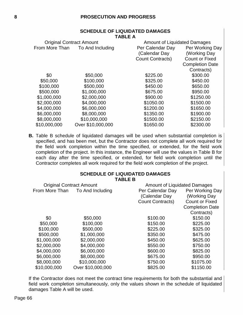
8 PROSECUTION AND PROGRESS
Page 66
SCHEDULE OF LIQUIDATED DAMAGES TABLE A
Original Contract Amount Amount of Liquidated Damages From More Than To And Including Per Calendar Day Per Working Day
(Calendar Day Count Contracts)
(Working Day Count or Fixed
Completion Date Contracts)
$0 $50,000 $225.00 $300.00 $50,000 $100,000 $325.00 $450.00 $100,000 $500,000 $450.00 $650.00 $500,000 $1,000,000 $675.00 $950.00
$1,000,000 $2,000,000 $900.00 $1250.00 $2,000,000 $4,000,000 $1050.00 $1500.00 $4,000,000 $6,000,000 $1200.00 $1650.00 $6,000,000 $8,000,000 $1350.00 $1900.00 $8,000,000 $10,000,000 $1500.00 $2150.00
$10,000,000 Over $10,000,000 $1650.00 $2300.00 B. Table B schedule of liquidated damages will be used when substantial completion is
specified, and has been met, but the Contractor does not complete all work required for the field work completion within the time specified, or extended, for the field work completion of the project. In this instance, the Engineer will use the values in Table B for each day after the time specified, or extended, for field work completion until the Contractor completes all work required for the field work completion of the project.
SCHEDULE OF LIQUIDATED DAMAGES TABLE B
Original Contract Amount Amount of Liquidated Damages From More Than To And Including Per Calendar Day Per Working Day
(Calendar Day Count Contracts)
(Working Day Count or Fixed
Completion Date Contracts)
$0 $50,000 $100.00 $150.00 $50,000 $100,000 $150.00 $225.00
$100,000 $500,000 $225.00 $325.00 $500,000 $1,000,000 $350.00 $475.00
$1,000,000 $2,000,000 $450.00 $625.00 $2,000,000 $4,000,000 $550.00 $750.00 $4,000,000 $6,000,000 $600.00 $825.00 $6,000,000 $8,000,000 $675.00 $950.00 $8,000,000 $10,000,000 $750.00 $1075.00 $10,000,000 Over $10,000,000 $825.00 $1150.00
If the Contractor does not meet the contract time requirements for both the substantial and field work completion simultaneously, only the values shown in the schedule of liquidated damages Table A will be used.
PROSECUTION AND PROGRESS 8
Page 67
8.9 SUSPENSION OF WORK ORDERED BY THE ENGINEER - If the performance of all or
any portion of the work is suspended or delayed by the Engineer in writing for an unreasonable period of time (not originally anticipated, customary, or inherent to the construction industry) and the Contractor believes that additional compensation or contract time or both is due as a result of such suspension or delay, the Contractor must submit to the Engineer in writing a request for adjustment within 7 calendar days of receipt of the notice to resume work. The request must set forth the reasons and support for such adjustment. Upon receipt, the Engineer will evaluate the Contractor's request in accordance with Section 5.17 or Section 8.7. If the Engineer agrees that the cost or time or both required for the performance of the contract has increased as a result of such suspension and the suspension was caused by conditions beyond the control of and not the fault of the Contractor, the Contractor’s suppliers, or subcontractors at any approved tier, and not caused by weather, the Engineer will make an adjustment (excluding profit) and modify the contract in writing accordingly. The Contractor will be notified of the Engineer's determination whether or not an adjustment of the contract is warranted. No contract adjustment will be allowed unless the Contractor has submitted the request for adjustment within the time prescribed. No contract adjustment will be allowed under this clause to the extent that performance would have been suspended or delayed by any other cause, or for which an adjustment is provided or excluded under any other term or condition of this contract.
8.10 DEFAULT AND TERMINATION OF CONTRACT - If the Contractor:
A. Does not perform the work with sufficient resources to assure the prompt completion of the work;
B. Does not perform the work in accordance with the Contract or neglects or refuses to
remove and replace rejected materials or unacceptable or unsuitable work;
C. Discontinues the prosecution of the work;
D. Does not resume work which has been discontinued within a reasonable time after notice to do so;
E. Becomes insolvent or is declared bankrupt, or commits any act of bankruptcy or
insolvency;
F. Allows any final judgement to remain unsatisfied for a period of 10 calendar days;
G. Makes an assignment for the benefit of creditors, without the Department's approval; or,
H. Does not carry on the work in an acceptable manner,
8 PROSECUTION AND PROGRESS
Page 68
The Engineer will give written notice to the Contractor and the Contractor's Surety of such delay, neglect, or default. If the Contractor or surety does not comply within 10 calendar days after the date of the written notice, the Department will have full power and authority without violating the contract to terminate the Contract and take the prosecution of the work out of the hands of the Contractor. The Department may use materials on the project and may enter into an agreement to complete the contract according to the terms and provisions thereof, or use such other methods as recommended by the Engineer for the completion of this contract. Costs and charges incurred by the Department, together with the cost of completing the work under contract, will be deducted from monies due or which may become due said Contractor. If such expense exceeds the sum which would have been payable under the contract, the Contractor and the Surety will be liable and will pay to the Department the amount of such excess.
8.11 TERMINATION OF CONTRACT - The Department may, by written order, terminate the
contract or any portion thereof after the Department determines that for reasons beyond the Department’s or Contractor’s control the Contractor is prevented from proceeding with or completing the work as originally contracted for, and termination would be in the public interest. Reasons for termination may include, but not be limited to, Executive Orders of the President relating to prosecution of war or national defense, national emergency which creates a serious shortage of materials, orders from duly constituted authorities relating to energy conservation, restraining orders or injunctions obtained by third-party citizen action resulting from national or local environmental protection laws or where the issuance of such order or injunction is primarily caused by acts or omissions of persons or agencies other than the Contractor.
When the Department terminates a contract effective on a certain date, the Department will pay for items of work completed as of that date at the contract bid price. The Department will pay for partially completed work either at agreed prices or by force account methods. The Department will pay for eliminated items as provided in Section 9.6.
The Department may, at the Department’s option, purchase from the Contractor, at actual cost delivered to a prescribed location, acceptable materials obtained by the Contractor which have not been incorporated into the project or otherwise disposed of as mutually agreed.
The Department may consider reimbursement for organization of the work, other overhead expense (when not otherwise included in the contract), and moving equipment and materials to and from the job; the intent being an equitable settlement with the Contractor. The Department will not consider the loss of anticipated profits in the settlement.
The Contractor will make all cost records available to the Department for determining validity and amount of each item claimed and to provide a basis for negotiating an equitable settlement.
PROSECUTION AND PROGRESS 8
Page 69
The Department’s termination of a contract, in whole or in part, will not relieve the Contractor of contractual responsibilities for the work completed, nor will it relieve the Surety of its obligation for and concerning any just claim arising out of the work performed.

8 PROSECUTION AND PROGRESS
Page 70
THIS PAGE INTENTIONALLY LEFT BLANK
MEASUREMENT AND PAYMENT 9
Page 71
9.1 MEASUREMENT OF QUANTITIES
A. General - The bid schedule specifies the unit of measure for each contract item. The Engineer will measure accepted quantities of work for each contract item in accordance with this section and the “Method of Measurement” subsection in the relevant specifications. In the case of a discrepancy, the method of measurement in the relevant specifications supersedes the method of measurement in this section. Unless the contract specifies otherwise, the Engineer will measure the actual quantity of accepted work for each contract item. A station when used as a definition or term of measurement will be 100 linear feet. The term “ton” will mean the short ton consisting of 2,000 pounds. When the contract item has a lump sum unit, the contract unit price is full compensation for the contract item. The method of measurement and computation to be used in determination of quantities of material furnished and of work performed under the contract will be those methods generally recognized as conforming to good engineering practice.
B. Area - The Engineer will make longitudinal measurements for area computations horizontally, with no deductions for individual fixtures having an area of 1 square yard or less. The Engineer will make transverse measurements for area computations by the neat dimensions shown on the plans or ordered in writing by the Engineer.
C. Structures - The Engineer will measure structures according to neat lines shown on the
plans or as altered to fit field conditions, except as otherwise provided in these specifications.
D. Linear Units - The Engineer will measure items which are measured by the foot,
including, but not limited to pipe culverts, guardrail, and underdrains, parallel to the base or foundation upon which such structures are placed, except as otherwise provided in these specifications.
E. Volume - For volume calculations, the Engineer will use the average end area method,
the prismoidal method, the truck/vehicle method, or other acceptable method. In computing volumes of excavation, the Engineer will use the average end area method or alternate computation methods, in the Engineer’s sole discretion.
F. Truck/Vehicle Volume - When using the truck/vehicle method, the Engineer will
measure the volume in a vehicle at the point of delivery. The Contractor will use vehicles which allow easy and accurate measurement of the contents. The Engineer may direct the Contractor to level the loads at the point of delivery to determine the actual volume of the load. The Contractor will not exceed the legal load limits for the gross weight.
9 MEASUREMENT AND PAYMENT
Page 72
G. Standard Manufactured Materials - The thickness of plates and galvanized sheet metal used in the manufacture of corrugated metal pipe, metal plate pipe culverts and arches, and metal cribbing will be specified and measured in decimal fractions of inches. The term "gauge," when used to refer to the measurement of wire, will mean the wire gauge; which will be specified and measured in decimal fractions of inches in accordance with the applicable specifications. When standard manufactured items are specified such as fence, wire, plates, rolled shapes, or pipe conduit, and these items are identified by size, gauge, unit weight, or section dimensions, the Engineer will consider this identification to be nominal weights or dimensions. Unless more stringently controlled by tolerances in cited specifications, the Engineer will accept manufacturing tolerances established by the industries involved.
H. Material Weight
1. General: The Engineer will measure asphalt materials by the ton. The Engineer may accept validated refinery weigh tickets accompanying bituminous materials transported from the refinery in truck transports, for measurement purposes. The Engineer will weigh asphalt materials shipped by rail in a manner determined by the Engineer, prior to use on the project. The Engineer will measure cement by the hundred weight. The Contractor will weigh materials on a certified scale and will issue weigh tickets. The Contractor will provide a scale operator to operate the scale and perform accuracy checks. The Contractor will furnish dust proof and watertight scale houses with satisfactory lighting and heating equipment.
Anytime during production the Engineer may call for checks, such as the accuracy check or adding known weights to the scale. a. Scale Certification: The Contractor will provide the Engineer with a letter or seal
of certification performed by a State Scale Inspector, a licensed private testing company, or a qualified representative of the scale manufacturer. The Department will certify portable platform scales and loader scales. The Department will use an accuracy check to certify portable platform scales and loader scales.

MEASUREMENT AND PAYMENT 9
Page 73
b. Accuracy: Except as provided elsewhere in the specifications, scales will be accurate within 0.5% at any point throughout the range of use of the scale. For asphalt plant scales, the 0.5% accuracy will be based on the net weight.
c. Accuracy Check: The Contractor will weigh a loaded truck on the nearest
certified scale. The Contractor will weigh the same loaded truck on the Contractor’s scale in at least two different positions and three if possible. The rear wheels should be positioned first on one end of the scale and then the other end. If the scale is long enough, weigh the truck again with the rear wheels in the center of the platform. The weights obtained must all be within 0.5% of the weight obtained on the certified scale. A piece of equipment with a fixed known weight may be used to ensure the scale accuracy at the same rate specified above, provided the piece of equipment being used to check the scale accuracy is fully fueled, free of mud and dirt, and weighs at least 60% of the maximum weight to be applied to the scale during the life of the project.
2. Trucks - Prior to performing hauling operations the Contractor will provide the Engineer with a list containing the following information for each truck that will be hauling on the project:
a. Truck, Trailer and Pup Identification Number(s) (or license number); b. Maximum Allowable Gross Weight (for the configuration to be used on the
project); c. Fully Fueled Tare Weight (including date and time of current tare); d. Number of tires per axle and tire sizes; and, e. Axle spacing. The Engineer may perform checks to verify the information provided by the Contractor. The Contractor will tare each unit, fully fueled, before hauling to the project and once a week thereafter. The Contractor will furnish the Engineer with a printout of each tared unit. The printout will include the tare weight, time, and date. The Engineer will verify the tare weight within one week of commencing use on the project and a minimum of once per project thereafter. Tractor-trailer combinations and truck-pup combinations may be weighed separately without uncoupling. The scale approaches will be level for a minimum of 100 feet or as approved by the Engineer, so the trailer or pup unit coupling does not transfer significant weight to the tractor or primary hauling unit to allow for accurate weighing. Each truck used to haul material being paid for by weight will bear a plainly legible identification and will be weighed empty at such times as the Engineer directs.
3. Contractor Computerized Scales: The Contractor will perform and document scale accuracy checks at the frequency outlined below on all computerized scales used on
9 MEASUREMENT AND PAYMENT
Page 74
the project and will submit a copy of the documentation to the Engineer once each week
a. Balance for zero load – The Contractor will perform this test twice daily.
b. Accuracy Check - The Contractor will check the scale accuracy prior to weighing
material for payment and then once each week thereafter. The Contractor will rerun the accuracy check if the scale is moved.
4. Portable Platform Scales: The Contractor will recertify a platform scale if the
platform scale is moved or sits over the winter months.
5. Stationary Commercial Scales and Plants: The Contractor may use a commercial scale or plant if the scale has been certified within the previous 12 months. All other checks may be omitted.
6. Portable Plant Scales: The Contractor will recertify a plant scale if the plant is
moved or sits over the winter months. 7. Belt Scales: The accuracy check will consist of the Contractor weighing an empty
truck on the nearest certified scale to determine the tare, then loading the truck using the belt scale, then re-weighing the truck on the same certified scale. The weight obtained from the belt scale must be within 0.5% of the net weight obtained on the certified scale. The Contractor will perform the accuracy check prior to weighing the material for payment and then once each week thereafter.
8. Loader Scales: A Contractor may use a loader scale on contracts if the quantity per
line item of granular material to be weighed for payment is less than 10,000 tons. The bucket used for certification and calibration will be the bucket used on the project. The Contractor will re-zero the weight of the bucket as needed. The accuracy check will consist of the Contractor weighing an empty truck on the nearest certified scale to determine the tare, then loading the truck using the loader scale in dynamic mode, then re-weighing the truck on the same certified scale. The weight obtained from the loader scale must be within 1.0% of the net weight obtained on the certified scale. The Contractor will perform the accuracy check prior to weighing the material for payment and then once each week thereafter. The Contractor may use an object with a fixed known weight to ensure the scale accuracy at the same rate specified above, provided the object being used to check the scale accuracy weighs at least 60% of the maximum weight being applied to the scale. The loading area will be level. Operation of the loader scale will be as recommended by the manufacturer for accurate weighing.
MEASUREMENT AND PAYMENT 9
Page 75
9. Automated Scale Tickets The Contractor will supply all scales with a computerized (automated) ticketing capability for all materials weighed for measurement and payment, unless otherwise specified in the plans. The Contractor will be responsible for the operation of the weighing system. The weighing system will automatically print the weigh tickets when the truck or pup identification number is entered into the system. The printed ticket will contain the following information: a. Ticket Number; b. Project Number or PCN; c. Date and Time Material is Weighed; d. Material Identification (Bid Item Number or Bid Item Description); e. Material Source; f. Truck (and Pup) Identification Number(s) (or license number); g. Maximum Allowable Gross Weight; h. Gross Weight; i. Fully Fueled Tare Weight (including date and time of current tare); j. Net Weight; k. Net Weight Allowed (loader scale only); l. Net Weight Loaded (loader and belt scales only); and, m. Spread. The ticket will contain the necessary information required by this section, unless otherwise approved by the Engineer. The Contractor will assure the tickets are clear and legible during the duration of the project. The Contractor will also provide a daily summary of the material hauled to the project, unless otherwise allowed by the Engineer.
10. Automated Weighing System
The automated weighing system must be capable of providing a security password allowing only authorized Department and supervisory Contractor personnel access to maximum allowable gross weight, tare weight, and net weight allowed (loader and belt scales only) input data and allowing only these authorized personnel to print the daily load summary by material type. The automated weighing system must generate a single ticket when tractor-trailer units cannot be simultaneously weighed, and must generate a separate ticket for pups, when the truck-pup combination cannot be simultaneously weighed. The Contractor will use truck and pup combinations in such a manner that correct gross, tare weights, and net weight allowed (loader and belt scales only) are entered into the automated weighing system. The Contractor will change or substitute a pup only after the Engineer has been notified and the maximum allowable gross weights and tare weights or net weight allowed (loader and belt scales only) are properly
9 MEASUREMENT AND PAYMENT
Page 76
entered into the automated weighing system and can accurately accommodate this type of change. The Contractor will program the automated weighing system so that when an overweight (illegal load) is on the scale, a ticket will not be printed, and an overload message with the gross weight will be displayed so that the overload amount is known allowing guidance to reduce the load prior to re-weighing and ticket printing.
The Contractor will program the loader scale so that when the net weight loaded is over the net weight allowed the loader operator may adjust the weight of the material in the bucket to allow the net weight loaded not to exceed the net weight allowed. The automated weighing system must automatically print the weigh ticket for each load of material when the truck driver or qualified Contractor scale person enters the truck or pup identification number. The Contractor will keep the weigh ticket with each load of material delivered to the project and will present the weigh ticket to the Engineer prior to unloading the material. The automated weighing system will provide the Engineer with a printed daily summary of the individual net weights with truck and pup identification numbers and the daily total weight by material type. All equipment, materials, labor, and incidentals required for the automated weighing system and scales will be incidental to the related contract items.
11. Inoperable Automated Weighing System
If the automated weighing system becomes inoperable during the work shift, the Department will allow the Contractor to continue if the Contractor furnishes a scale operator to perform the weighing duties according to the specified requirements. If the automated weighing system is not fully operational within 2 working days following the effected work shift, the Contractor will not be allowed to continue. If the automated weighing system becomes inoperable, the Contractor will furnish an experienced scale operator fully capable of accurately operating a permanent commercial scale or a portable automated scale system. The Contractor furnished scale operator is subject to the Engineer’s approval. If a loader scale or belt scale becomes inoperable during the work shift, the Contractor may not complete the effected work shift unless another certified scale is available.
I. Weight and Volume Conversion - When requested by the Contractor and approved by
the Engineer, the Engineer will convert weight measurement to volume measurement or volume measurement to weight measurement for payment purposes. The Engineer and the Contractor will agree to factors for conversion before using this method of measurement of pay quantities.
MEASUREMENT AND PAYMENT 9
Page 77
J. Timber - The Engineer will measure timber by the thousand board foot measure of material incorporated in the work. The Engineer will base measurement on nominal widths and thicknesses and the extreme length of each piece.
K. Lump Sum Items - The term "lump sum" when used as an item of payment will mean
complete payment for the work described in the contract. When a complete structure or structural unit (in effect, "lump sum" work) is specified as the unit of measurement, the Engineer will construe the unit to include necessary fittings and accessories.
L. Equipment Rental - The Engineer will measure rental of equipment in hours of actual working time of the equipment within the limits of the project, except when special conditions make some other method of measurement desirable.
9.2 SCOPE OF PAYMENT - The Contractor will receive and accept compensation provided for
in the contract as full payment for furnishing materials and for performing work under the contract in a complete and acceptable manner and for risk, loss, damage, or expense of whatever character arising out of the nature of the work or the prosecution thereof, subject to the provisions of Section 7.20.
Payment for an item of work will include full compensation for furnishing labor, materials, equipment, and incidentals required to complete the work not specifically measured and paid for under a separate bid item.
If the "Basis of Payment" clause in the specifications relating to unit price in the bid schedule requires the said unit price cover and be considered compensation for certain work or material essential to the item, this same work or material will not also be measured or paid for under any other pay item which may appear elsewhere in the specifications.
9.3 PAYMENT FOR EXTRA HAUL OF MATERIALS - If, through no fault of the Contractor,
increase in the average haul provided in the contract results when subgrade, subbase, base course, or surfacing materials (including clay and filler) cannot be secured and used as shown on the plans, or through a change in the plans, the Engineer will adjust the rate per ton mile at the rate specified in the Special Provision for Price Schedule for Miscellaneous Items. Average haul provided in the contract is obtained by dividing the haul units shown in the contract for a material by the contract quantity of the material. Payment for extra haul as provided in this specification will be full compensation for moving equipment, delays in operation, additional labor, equipment, and other costs involved. The Engineer will include extra haul as a new item on a Construction Change Order and approval must be obtained prior to performing the work.
9.4 COMPENSATION FOR ALTERED QUANTITIES - When the accepted quantities of work
vary from the estimated quantities in the Contract, the Contractor will accept payment at the original contract unit prices for the accepted quantities of work as payment in full. The Engineer will make no allowance for increased expense, except as provided in Section 4.3. Engineer will make no allowance for loss of expected reimbursement or loss of anticipated profits.

9 MEASUREMENT AND PAYMENT
Page 78
9.5 EXTRA AND FORCE ACCOUNT WORK – The Department may agree to pay for extra
work performed in accordance with the requirements and provisions of Section 4.4 at the agreed prices stipulated in the order authorizing the extra work (DOT-228). In the absence of agreement, the Department may require the Contractor to perform extra work on a force account basis to be compensated in the following manner:
A. Labor: For labor and supervisor in direct charge of the specific operations, the
Contractor will receive the rate of wage agreed upon in writing before beginning work or the actual rate paid in the event actual rate paid is less than the agreed rate, for each hour said labor and supervisor are actually engaged in such work.
If a laborer or supervisor is paid for "overtime" during a calendar week and the laborer or supervisor is employed for part of that period on force account work, the Department will pay to the Contractor a percentage of that portion of the overtime payment determined by the ratio which the total hours worked on force account during the week bears to the total hours worked during that week.
The Department will pay, at 100%, overtime incurred due to the Department requiring the Contractor to do force account work during periods not normally worked. To allow the Engineer to verify wages paid and prorate overtime, the Contractor will furnish to the Engineer certified payrolls during the period force account work is in progress. The Department will also pay the Contractor an amount equal to 15% of the sum for labor as compensation for administrative and overhead costs.
B. Insurance and Tax: The Department will pay the Contractor the actual cost of property
damage, liability, and workers’ compensation insurance premiums; unemployment insurance contributions; and social security taxes on the force account work, with no percentage added. The Contractor will furnish the Engineer with satisfactory evidence of the rate or rates paid for such insurance and tax. In lieu of furnishing itemized statements to substantiate the costs of property damage, liability, and workers’ compensation insurance premiums; unemployment insurance contributions; and Social Security tax, the Contractor may elect to receive an amount equal to 25.1% of the actual labor costs, excluding the 15% for administrative and overhead costs, as compensation for those costs.
C. Materials: The Department will pay the Contractor the actual cost of materials accepted
by the Engineer and incorporated into the project, including transportation charges paid by the Contractor, exclusive of equipment rentals as set forth in Section 9.5 D. The Department will add 15% to material and transportation costs as compensation for administrative and overhead costs.
D. Equipment: The Department will pay the Contractor for machinery and special
equipment, including fuel, lubricants, and transportation costs authorized by the Engineer. The Department will pay these costs at the rates set forth in the South Dakota Equipment Rental Rates Book, which is currently established as the “Rental Rate Blue
MEASUREMENT AND PAYMENT 9
Page 79
Book” published by EquipmentWatch, a division of Penton Media, Inc. To determine an hourly rate, the Department will divide the monthly rate by 176. The Department will adjust this rate for regional factors, age, and operating expenses as set forth in the “Rental Rate Blue Book”.
Standby rates will apply when the work requires a piece of equipment not already on the project be brought in and, through no fault of the Contractor; the equipment is on standby status. Standby rates will be 50% of the normal base rates without the operating expenses. Standby rates will not exceed 8 hours per day or 40 hours per week. When a unit works for a portion of a day and is on standby for a portion, the total time allowed will not exceed 8 hours for that day.
The costs for move in and move out of equipment not already on the project will be at standby rates. This is in addition to the applicable rates for the hauling unit moving in and returning empty to its point of origin.
Equipment will be paid for at invoice prices if necessary equipment is not of a type owned by the Contractor or if equipment is available in the area at a cost less than the cost of paying force account including move in and move out, for Contractor owned equipment.
E. Miscellaneous: The Engineer will make no additional allowance for general
superintendence or other costs for which no specific allowance is provided in these specifications.
F. Compensation: The Contractor's representative and the Engineer will compare records
of the cost of work done as ordered on a force account basis. G. Statements: The Department will pay for work performed by force account based on
itemized statements of the cost of such force account work detailed as follows:
1. Name, classification, date, daily hours, total hours, rate, and extension for each laborer and foreman;
2. Designation, dates, daily hours, total hours, rental rate, and extension for each unit
of machinery and equipment;
3. Quantities of materials, prices, and extensions;
4. Transportation of materials; and,
5. Cost of property damage, liability, and workers’ compensation insurance premiums; unemployment insurance contributions; and social security tax.
The Contractor will support each statement by attaching paid invoices for rented equipment and materials used, including transportation charges. However, if materials used on the force account work are not specifically purchased for such work but are taken from the Contractor's stock, the Contractor will furnish an affidavit certifying the
9 MEASUREMENT AND PAYMENT
Page 80
following: The materials were taken from the Contractor’s stock, the quantity claimed was actually used, and the price and transportation claimed represent the actual cost to the Contractor.
H. Subcontracting: When a subcontractor performs work on a force account basis in
accordance with the provisions of an extra work order, the Engineer will allow the prime Contractor a percentage for the administrative expenses incurred in connection with the work. This administrative allowance will be based on the following table and is applicable to charges for labor and materials only and will be applied to all charges and added percentages specified in paragraphs A and C above. Bid items in the original contract are not eligible for this administrative allowance.
$ 0 to $1,000.00 .......................................................................................... 10% $ 1,000.01 to $10,000.00 .......................... $100 plus 5% of excess over $1000 $10,000.01 and over .............................. $550 plus 3% of excess over $10,000
I. Profit: The Department will add 10% to the sum of items A through C for profit. J. Excise Tax: The Department will add applicable excise tax due to the South Dakota
Department of Revenue. The Department will compute the excise tax from the final total of items A through I.
9.6 ELIMINATED ITEMS - If the Engineer finds items contained in the Contract unnecessary
for the completion of the work, the Engineer will eliminate these items from the contract by written order to the Contractor. This elimination of items will not invalidate the contract or be cause for any action against the Department. If an item is eliminated, the Department will reimburse the Contractor for work completed and all costs incurred, together with the cost of transportation of materials prior to said notification, and the cost related to return of unused materials to the supplier. In lieu of reimbursement for the return of eliminated material, the Department may elect to purchase this material at the Contractor’s actual cost.
The Department will not make payment due to elimination of pile shoes regardless of work done or materials purchased by the Contractor prior to notification of the elimination of this item.
9.7 PROGRESS PAYMENTS - The Department will make partial payments at least once each
month as the work progresses, if the total value of work done since the last estimate amounts to $500 or more. The Department will make partial payments twice each month if the amount of work performed is sufficient to warrant such payment.
The Contractor may submit items and quantities that may warrant the Engineer’s consideration for payment on an estimate.
The Departments payments will be based upon estimates prepared by the Engineer of the value of the work performed and materials complete in place in accordance with the contract and for materials delivered in accordance with Section 9.8. Progress payments will not constitute acceptance of the work.
MEASUREMENT AND PAYMENT 9
Page 81
From the total amount determined payable, the Engineer will deduct payments due the landowner, as provided under Section 6.2. For each working day or calendar day counted after the contract time specified for the work as extended, the Engineer will retain the appropriate amount shown in the schedule of liquidated damages (Section 8.8) from the amount payable.
9.8 PAYMENT FOR MATERIALS DELIVERED TO PROJECT - The Department will not pay
for materials delivered to, or stockpiled on, the project until incorporated in the work in final position, except as specified hereinafter.
The Department may make partial payments upon the Contractor’s written request on specific items which will form a part of the completed work and which are stockpiled in a manner and location satisfactory to the Engineer. The Department will not pay for structural or reinforcing steel prior to fabrication, except the Department may make partial payment on structural steel to be used in bridge girders when requested in writing by the Contractor. The Department will make partial payment only for structural steel delivered to and stockpiled at the fabrication shop. The Contractor may request partial payment for structural steel for bridge girders only once throughout the duration of the project.
The Department may pay for mulch and seed provided the Contractor has satisfactory precautions in place to ensure proper storage.
If stored materials are lost or damaged, the Contractor will repair and replace the lost or damaged materials. If the Department has made prior payment, the Department will deduct the amount allowed, in whole or a proportionate part, from the next partial payment until the materials have been satisfactorily repaired or replaced.
The Department will pay for stockpiled materials on the basis of the quantities placed in storage.
The rate of payment will be on the basis of actual costs as evidenced by a delivery invoice or other satisfactory evidence of cost furnished by the Contractor. The payment will not exceed the contract amount or contract unit price for the item involved.
The Contractor must supply a delivery invoice or invoices for all stockpiled materials, except materials manufactured by the Contractor which the Department will pay according to the percentage established in the following table.
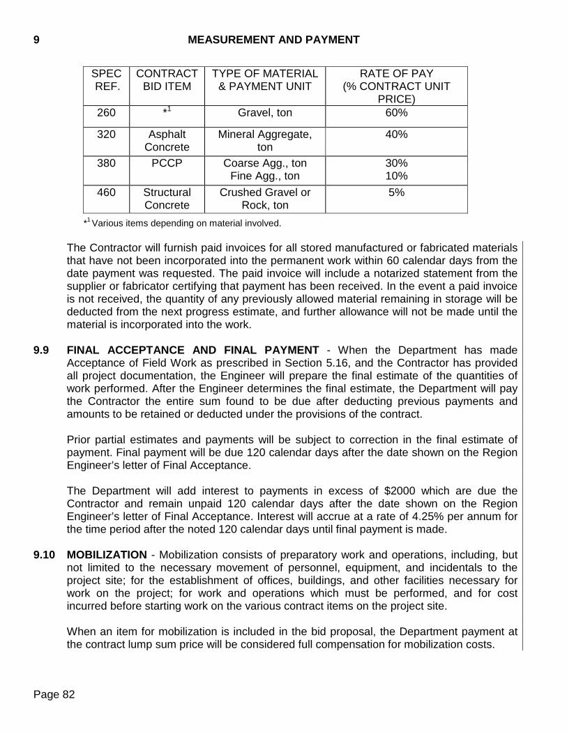
9 MEASUREMENT AND PAYMENT
Page 82
SPEC REF.
CONTRACT BID ITEM
TYPE OF MATERIAL & PAYMENT UNIT
RATE OF PAY (% CONTRACT UNIT
PRICE) 260 *1 Gravel, ton 60%
320 Asphalt Concrete
Mineral Aggregate, ton
40%
380 PCCP Coarse Agg., ton Fine Agg., ton
30% 10%
460 Structural Concrete
Crushed Gravel or Rock, ton
5%
*1 Various items depending on material involved.
The Contractor will furnish paid invoices for all stored manufactured or fabricated materials that have not been incorporated into the permanent work within 60 calendar days from the date payment was requested. The paid invoice will include a notarized statement from the supplier or fabricator certifying that payment has been received. In the event a paid invoice is not received, the quantity of any previously allowed material remaining in storage will be deducted from the next progress estimate, and further allowance will not be made until the material is incorporated into the work.
9.9 FINAL ACCEPTANCE AND FINAL PAYMENT - When the Department has made
Acceptance of Field Work as prescribed in Section 5.16, and the Contractor has provided all project documentation, the Engineer will prepare the final estimate of the quantities of work performed. After the Engineer determines the final estimate, the Department will pay the Contractor the entire sum found to be due after deducting previous payments and amounts to be retained or deducted under the provisions of the contract.
Prior partial estimates and payments will be subject to correction in the final estimate of payment. Final payment will be due 120 calendar days after the date shown on the Region Engineer’s letter of Final Acceptance.
The Department will add interest to payments in excess of $2000 which are due the Contractor and remain unpaid 120 calendar days after the date shown on the Region Engineer’s letter of Final Acceptance. Interest will accrue at a rate of 4.25% per annum for the time period after the noted 120 calendar days until final payment is made.
9.10 MOBILIZATION - Mobilization consists of preparatory work and operations, including, but not limited to the necessary movement of personnel, equipment, and incidentals to the project site; for the establishment of offices, buildings, and other facilities necessary for work on the project; for work and operations which must be performed, and for cost incurred before starting work on the various contract items on the project site.
When an item for mobilization is included in the bid proposal, the Department payment at the contract lump sum price will be considered full compensation for mobilization costs.
MEASUREMENT AND PAYMENT 9
Page 83
The Department will make partial payments on the following schedule: A. When the contract has been fully executed by parties thereto, the Department will make
a partial mobilization payment as determined by the following schedule, except the payment will not exceed 25% of the total amount bid for mobilization.
1. Contract amounts up to and including $500,000.
Payment in an amount equal to 1.0% of contract amount.
2. Contract amounts in excess of $500,000.
Payment in an amount equal to $5,000. plus 0.60% of contract amount in excess of $500,000.
B. When 5%, or more, of the original contract amount is earned, an additional amount will
be paid to bring the total payment for mobilization to 25% of the amount bid.
C. When 10%, or more, of the original contract amount is earned, an additional amount will be paid to bring the total payment for mobilization to 50% of the amount bid.
D. When 25%, or more, of the original contract amount is earned, an additional amount will
be paid to bring the total payment for mobilization to 60% of the amount bid.
E. When 50%, or more, of the original contract amount is earned, a final payment will be made to bring the total payment for mobilization to 100% of the amount bid.
When an item for "mobilization" is not included in the proposal, this work will be considered as incidental to the various contract items.
9.11 FREIGHT RATES - Bidders will fully inform themselves as to the source of supply of acceptable materials needed for the performance of the work and as to carrier rates and other transportation costs and facilities for these materials before submitting proposals.
Changes in carrier rates or in the cost of other transportation facilities used for materials during the life of the Contract will not constitute cause for a claim for additional compensation.
9.12 FUEL COST ADJUSTMENT - The Engineer will determine compensation adjustments for motor fuels and burner fuels consumed in prosecuting the work in accordance with the following provisions: A. General: The Engineer will assess compensation adjustments for the cost of the motor
fuels and burner fuels whenever the Current Fuel Index (CFI) is outside the range of 85% to 115% of the Base Fuel Index (BFI). The Engineer will only make compensation adjustments for burner fuel when asphalt concrete bid items are paid for on the estimate.
9 MEASUREMENT AND PAYMENT
Page 84
The Contractor is not required to notify the Department at the time of submitting a bid proposal whether the Contractor will or will not participate in the fuel cost adjustment program. Prior to execution of the contract, the successful bidder must submit a completed Fuel Adjustment Affidavit (Form DOT-208), included in the proposal or available from the Department, to the Department for approval. Determination of whether to participate in the Fuel Adjustment program is the decision of the prime Contractor. If the prime Contractor decides not to participate, or if the prime Contractor has a fixed fuel cost for any of the fuel types, the Department will make no compensation adjustment for the subcontractors. If the prime Contractor chooses to participate in the fuel cost adjustment program, the Fuel Adjustment Affidavit (Form DOT-208) must include the anticipated fuel cost of subcontractors. If compensation adjustments are made, the prime Contractor will ensure all subcontractors including second and lower tier, are included in the adjustments in proportion to the percentage of work and anticipated fuel cost by that subcontractor. Each week the Department will record the average wholesale price for #2 fuel oil (diesel), regular unleaded gasoline, and propane (LPG), Freight On Board (FOB) South Dakota terminals, as listed in the “Oil Price Information Service” (OPIS) publication. The BFI price for motor fuels and burner fuel to be used in the contract will be the average of the recorded wholesale fuel prices for the four most recent weekly reporting periods prior to the week of the bid letting. The CFI price for motor fuels and burner fuel to be used for each progress payment will be the average for the recorded wholesale fuel prices for the four most recent weekly reporting periods available at the time when the progress payment is prepared. Burner fuel adjustment will use the BFI and CFI as determined for #2 fuel oil (diesel), except when the Contractor lists the burner fuel as propane (LPG) on the Fuel Adjustment Affidavit (Form DOT-208). In that case, the BFI and CFI will be as determined for propane (LPG). The Engineer will not assess compensation adjustments for fuel items which the Contractor has obtained a fixed fuel cost, or if the Contractor elects not to participate in fuel adjustments on the Fuel Adjustment Affidavit (Form DOT-208). Fixed fuel costs are defined as a fuel cost that has been set and will remain the same for the entire length of the contract. The Engineer may make compensation adjustments in accordance with these provisions on progress payments without a prior approved Construction Change Order.
B. Fuel Cost Percentage Change: The Engineer will determine the biweekly change in fuel cost percentage by Equation 1 as follows:
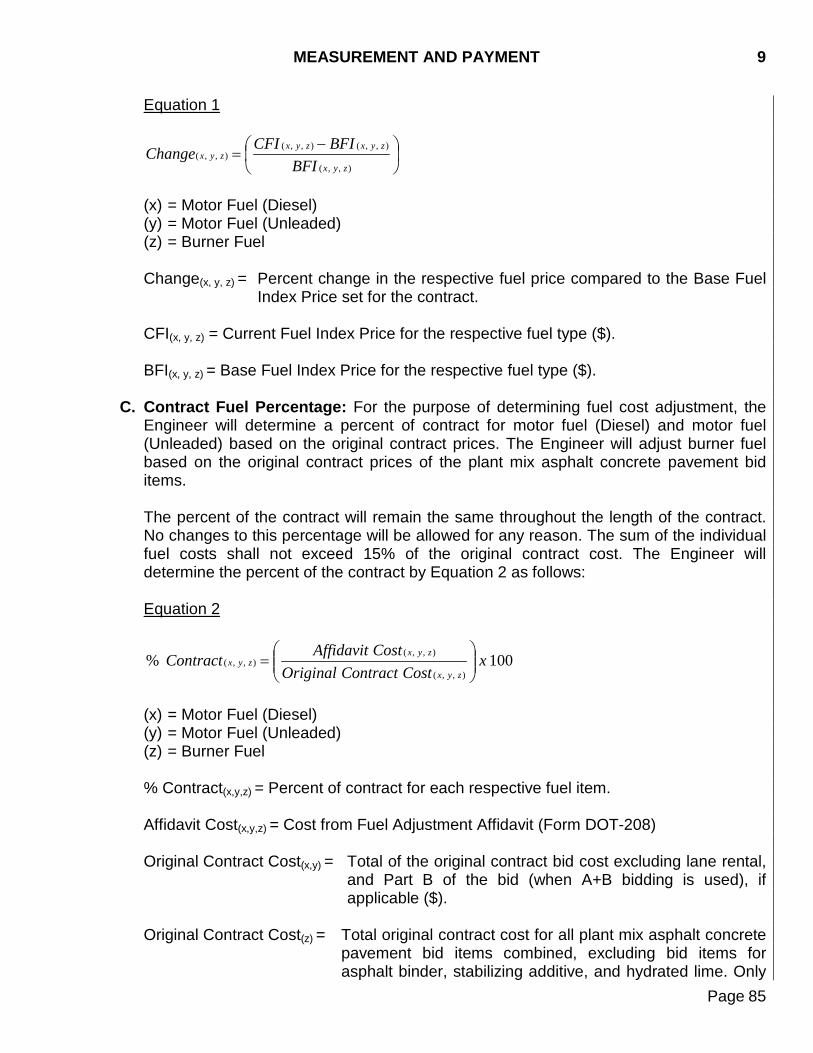
MEASUREMENT AND PAYMENT 9
Page 85
Equation 1
−
=),,(
),,(),,(),,(
zyx
zyxzyxzyx
BFIBFICFIChange
(x) = Motor Fuel (Diesel) (y) = Motor Fuel (Unleaded) (z) = Burner Fuel Change(x, y, z) = Percent change in the respective fuel price compared to the Base Fuel
Index Price set for the contract. CFI(x, y, z) = Current Fuel Index Price for the respective fuel type ($). BFI(x, y, z) = Base Fuel Index Price for the respective fuel type ($).
C. Contract Fuel Percentage: For the purpose of determining fuel cost adjustment, the Engineer will determine a percent of contract for motor fuel (Diesel) and motor fuel (Unleaded) based on the original contract prices. The Engineer will adjust burner fuel based on the original contract prices of the plant mix asphalt concrete pavement bid items. The percent of the contract will remain the same throughout the length of the contract. No changes to this percentage will be allowed for any reason. The sum of the individual fuel costs shall not exceed 15% of the original contract cost. The Engineer will determine the percent of the contract by Equation 2 as follows: Equation 2
100%),,(
),,(),,( x
CostContractOriginalCostAffidavitContract
zyx
zyxzyx
=
(x) = Motor Fuel (Diesel) (y) = Motor Fuel (Unleaded) (z) = Burner Fuel % Contract(x,y,z) = Percent of contract for each respective fuel item. Affidavit Cost(x,y,z) = Cost from Fuel Adjustment Affidavit (Form DOT-208) Original Contract Cost(x,y) = Total of the original contract bid cost excluding lane rental,
and Part B of the bid (when A+B bidding is used), if applicable ($).
Original Contract Cost(z) = Total original contract cost for all plant mix asphalt concrete
pavement bid items combined, excluding bid items for asphalt binder, stabilizing additive, and hydrated lime. Only
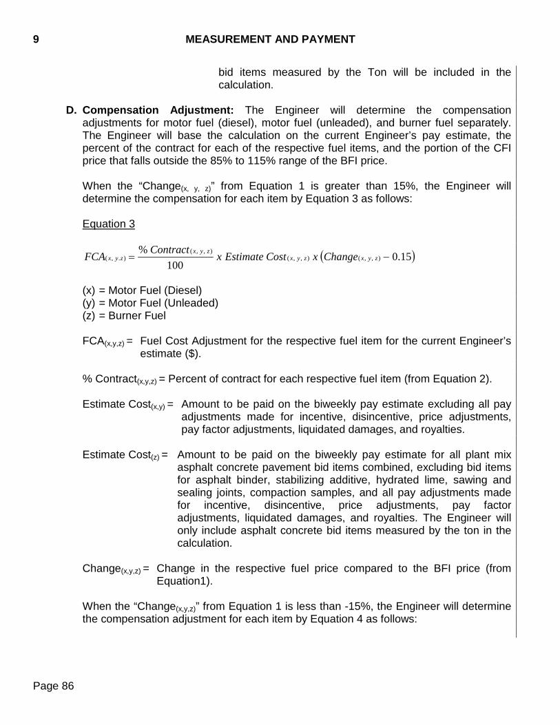
9 MEASUREMENT AND PAYMENT
Page 86
bid items measured by the Ton will be included in the calculation.
D. Compensation Adjustment: The Engineer will determine the compensation
adjustments for motor fuel (diesel), motor fuel (unleaded), and burner fuel separately. The Engineer will base the calculation on the current Engineer’s pay estimate, the percent of the contract for each of the respective fuel items, and the portion of the CFI price that falls outside the 85% to 115% range of the BFI price. When the “Change(x, y, z)” from Equation 1 is greater than 15%, the Engineer will determine the compensation for each item by Equation 3 as follows: Equation 3
( )15.0100
%),,(),,(
),,().,( −= zyxzyx
zyxzyx ChangexCostEstimatexContractFCA
(x) = Motor Fuel (Diesel) (y) = Motor Fuel (Unleaded) (z) = Burner Fuel FCA(x,y,z) = Fuel Cost Adjustment for the respective fuel item for the current Engineer’s
estimate ($). % Contract(x,y,z) = Percent of contract for each respective fuel item (from Equation 2). Estimate Cost(x,y) = Amount to be paid on the biweekly pay estimate excluding all pay
adjustments made for incentive, disincentive, price adjustments, pay factor adjustments, liquidated damages, and royalties.
Estimate Cost(z) = Amount to be paid on the biweekly pay estimate for all plant mix
asphalt concrete pavement bid items combined, excluding bid items for asphalt binder, stabilizing additive, hydrated lime, sawing and sealing joints, compaction samples, and all pay adjustments made for incentive, disincentive, price adjustments, pay factor adjustments, liquidated damages, and royalties. The Engineer will only include asphalt concrete bid items measured by the ton in the calculation.
Change(x,y,z) = Change in the respective fuel price compared to the BFI price (from
Equation1). When the “Change(x,y,z)” from Equation 1 is less than -15%, the Engineer will determine the compensation adjustment for each item by Equation 4 as follows:
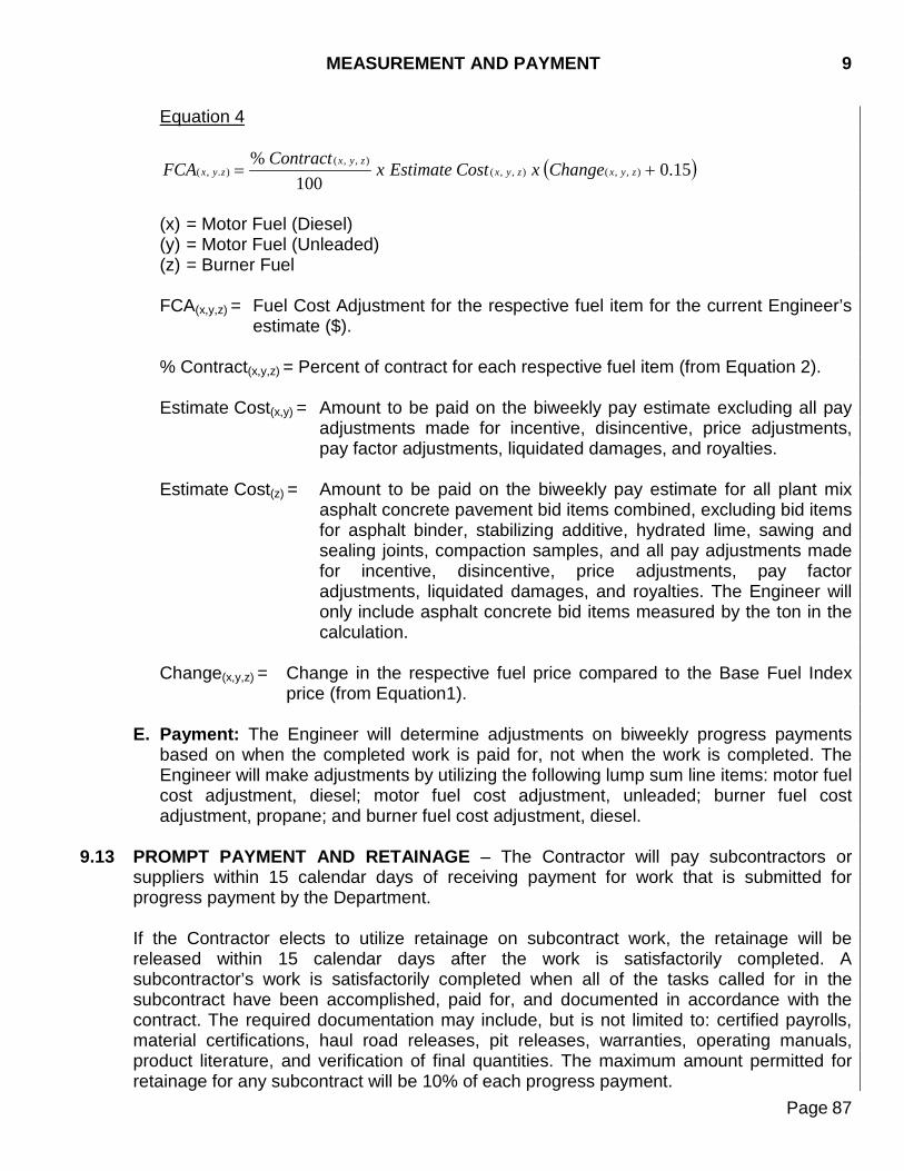
MEASUREMENT AND PAYMENT 9
Page 87
Equation 4
( )15.0100
%),,(),,(
),,().,( += zyxzyx
zyxzyx ChangexCostEstimatexContractFCA
(x) = Motor Fuel (Diesel) (y) = Motor Fuel (Unleaded) (z) = Burner Fuel FCA(x,y,z) = Fuel Cost Adjustment for the respective fuel item for the current Engineer’s
estimate ($). % Contract(x,y,z) = Percent of contract for each respective fuel item (from Equation 2). Estimate Cost(x,y) = Amount to be paid on the biweekly pay estimate excluding all pay
adjustments made for incentive, disincentive, price adjustments, pay factor adjustments, liquidated damages, and royalties.
Estimate Cost(z) = Amount to be paid on the biweekly pay estimate for all plant mix
asphalt concrete pavement bid items combined, excluding bid items for asphalt binder, stabilizing additive, hydrated lime, sawing and sealing joints, compaction samples, and all pay adjustments made for incentive, disincentive, price adjustments, pay factor adjustments, liquidated damages, and royalties. The Engineer will only include asphalt concrete bid items measured by the ton in the calculation.
Change(x,y,z) = Change in the respective fuel price compared to the Base Fuel Index
price (from Equation1).
E. Payment: The Engineer will determine adjustments on biweekly progress payments based on when the completed work is paid for, not when the work is completed. The Engineer will make adjustments by utilizing the following lump sum line items: motor fuel cost adjustment, diesel; motor fuel cost adjustment, unleaded; burner fuel cost adjustment, propane; and burner fuel cost adjustment, diesel.
9.13 PROMPT PAYMENT AND RETAINAGE – The Contractor will pay subcontractors or suppliers within 15 calendar days of receiving payment for work that is submitted for progress payment by the Department. If the Contractor elects to utilize retainage on subcontract work, the retainage will be released within 15 calendar days after the work is satisfactorily completed. A subcontractor’s work is satisfactorily completed when all of the tasks called for in the subcontract have been accomplished, paid for, and documented in accordance with the contract. The required documentation may include, but is not limited to: certified payrolls, material certifications, haul road releases, pit releases, warranties, operating manuals, product literature, and verification of final quantities. The maximum amount permitted for retainage for any subcontract will be 10% of each progress payment.
9 MEASUREMENT AND PAYMENT
Page 88
The prompt payment and release of retainage applies to all tiers of subcontracts. If the Contractor withholds payment beyond these time periods, the Contractor will submit written justification to the Engineer upon request. If the Engineer determines a subcontractor or supplier has not received payment due without just cause, the Department may withhold future estimated payments and may direct the prime contractor to make such payment to the subcontractor or supplier. Prompt payment and release of retainage deviations will be subject to price adjustments as specified in Section 5.3.
DIVISION II 100 CONSTRUCTION DETAILS PART A EARTHWORK
CLEARING AND GRUBBING
Page 89
100.1 DESCRIPTION
This work consists of clearing, grubbing, removing, and disposing of vegetation and debris within the limits of the right-of-way, borrow, and easement areas except objects designated to be removed in accordance with other sections of these specifications.
100.2 MATERIALS (Not Specified) 100.3 CONSTRUCTION REQUIREMENTS
Before clearing activities begin, the Contractor shall contact the Engineer to determine the limits of clearing for the project. The Engineer will establish right-of-way lines and construction lines and designate trees, shrubs, plants, and other objects to remain. Vegetation and objects designated to remain shall be preserved free from injury or defacement. If the Contractor injures or defaces any item designated to remain, the Contractor shall replace the designated item with an item of the same size and type at the Contractor’s expense. Surface objects, trees, stumps, roots, and other protruding obstructions designated for removal shall be cleared and grubbed, including mowing, as required. When authorized, the Contractor may leave stumps and nonperishable solid objects extending more than 3 feet below subgrade or slope of embankments, provided the stumps and nonperishable solid objects do not extend more than 4 inches above the finished ground line or low water level. In embankment areas, holes resulting from the removal of obstructions shall be backfilled with suitable material and compacted in accordance with Section 120.3 B.3. Burning, if permitted, shall be done in accordance with applicable laws, ordinances, and regulations. Perishable material shall be burned under the Contractor’s constant care and in a manner that will not jeopardize the surrounding vegetation, adjacent property, or anything designated to remain. Materials, debris, residue from burning, and unburned perishable materials shall be satisfactorily disposed of. If disposal is by burial, a cover of at least 12 inches shall be provided and the area shall be shaped to present a pleasing appearance. If the disposal location is off the project, the Contractor shall make arrangements with property owners in writing for obtaining suitable disposal locations. These sites shall be outside the limits of view from the project. The cost involved shall be incidental to the corresponding items listed in Section 100.5. Timber which can be utilized for logs, posts, poles, ties, or cordwood shall be considered as merchantable timber and shall be the property of the previous landowner. When specified in the contract, the timber shall be trimmed, cut into merchantable lengths, and neatly piled
100 CLEARING AND GRUBBING
Page 90
adjacent to the right-of-way at designated locations. The Contractor will not be required to cut merchantable timber into lengths shorter than 16 feet. Low hanging, unsound, or unsightly branches on remaining trees or shrubs shall be removed. Branches of trees extending over the roadbed shall be trimmed to give a clear height of 20 feet above the roadbed surface. Branches of trees extending over the sidewalk shall be trimmed to give a clear height of 8 feet above the sidewalk surface. Trimming shall be done in accordance with good tree trimming practices.
100.4 METHOD OF MEASUREMENT
Measurement for clearing and grubbing trees and stumps over 6 inches in diameter will be on a per each basis by actual count of such trees and stumps removed and disposed of. The diameter of trees and stumps will be measured 2 feet above the ground. Old stumps extending less than 2 feet above the ground will not be counted. No more than one tree will be counted from any stump. When the contract stipulates that payment will be made for clearing on a lump sum basis, no separate measurement will be made.
100.5 BASIS OF PAYMENT
The removal of trees and stumps will be paid for at the contract unit price per each. When the removal of trees and stumps is not included in the contract, the removal of trees and stumps will be incidental to the lump sum price for clearing. The lump sum payment for clearing will be full compensation for removal and disposal of vegetation and debris.
REMOVAL OF STRUCTURES AND OBSTRUCTIONS 110
Page 91
110.1 DESCRIPTION This work consists of removal and disposal of buildings, fences, structures, pavements, abandoned pipe lines, pipe culverts, other obstructions which are not designated or permitted to remain, and other obstructions which are not removed and disposed of under other items in the contract. This work shall also include the salvaging of designated materials and backfilling the resulting trenches, holes, and pits.
110.2 MATERIALS (Not Specified) 110.3 CONSTRUCTION REQUIREMENTS
Designated salvageable material shall be carefully removed, in sections or pieces which may be readily transported, and shall be stored at places specified. Unusable perishable material shall be destroyed. Nonperishable material may be disposed of outside the limits of view from the project with written permission of the property owner. Pipe shall be removed and disposed of as nonperishable material. Basements or cavities left by structure removal shall be filled to the level of the surrounding ground and, if located in an area of an embankment or other structure, shall be compacted under the same specification as the embankment. In other areas the fill material shall be compacted as necessary to preclude undue settlement and shall be slightly mounded. Concrete basement floors and similar structures shall be broken up to prevent entrapment of water. The Contractor shall be responsible for the disconnection and capping of all utility services to the building. Bridges, culverts, and other drainage structures used by traffic shall not be removed until satisfactory arrangements have been made to accommodate traffic. The substructures of existing structures shall be removed down to the natural stream bottom. Those parts outside the stream shall be removed down to 1 foot below the finished ground elevation. When portions of existing structures are within the limits of a new structure, these portions shall be removed as necessary to accommodate the construction of the proposed structure. All designated salvageable steel or wood bridges shall be dismantled without damage. Structures designated to become the property of the Contractor shall be removed from the right-of-way. Blasting or other operations necessary for the removal of an existing structure or obstruction, which may damage new construction, shall be completed prior to placing the new work. Pipe to be reset shall be removed, transported to the site of installation, and stored so there will be no damage before resetting. The Contractor will be required to replace sections of pipe damaged by negligence at the Contractor’s own expense.
110 REMOVAL OF STRUCTURES AND OBSTRUCTIONS
Page 92
In removing curb, gutter, sidewalk, and similar structures, where portions of the existing structures are to be left in the finished work, the old structure shall be removed to an existing joint or sawed and chipped to a true line with a vertical face. Where new PCC pavement or new AC pavement is placed adjacent to existing AC or PCC pavement, the existing pavement shall be sawed full depth to a true line with a vertical face. When removing manholes, catch basins, or drop inlets, any functioning sewer lines connected to them shall be rebuilt and properly connected. Satisfactory by-pass service shall be maintained during construction operations.
110.4 METHOD OF MEASUREMENT When the contract stipulates that payment will be made for removal of obstructions on a lump sum basis, no separate measurement will be made. When the contract stipulates that payment will be made for the removal of specific items on a unit basis, measurement will be made by the unit stipulated in the contract. When removal of pipe is to be made on a unit basis, the quantity will be measured in linear feet. End sections will be measured in linear feet as part of the overall length of pipe unless otherwise stipulated in the contract. Where curb and gutter adjoins Portland cement concrete pavement to be removed, the curb and gutter will be considered as pavement and will be measured as such.
110.5 BASIS OF PAYMENT Removal of obstructions on a lump sum basis will be paid for as per Section 250. Removal of pipe not designated for salvage will be paid for as per Section 250. Variance from plan shown pipe removal quantities, locations, or dimensions will not be cause for adjustment in payment for incidental work. Payment for removal of obstructions on a unit basis will be made under the contract item “Remove *****” Payment for removal of obstructions, by either lump sum or on a unit basis, will be full compensation for removal and disposal of such items, excavation, and subsequent backfill incidental to the removal. Payment will also include salvage of materials removed and their custody, preservation, storage on the right-of-way, and disposal as specified. When the contract does not include bid items for removal of structures and obstructions as set out in this section, the cost for this work shall be incidental to the various other contract items.
ROADWAY AND DRAINAGE EXCAVATION 120 AND EMBANKMENT CONSTRUCTION
Page 93
120.1 DESCRIPTION
This work consists of excavation, placement and disposal of material necessary for the construction of the roadway including hauling, watering, and when required, the placement of select subgrade topping.
120.2 MATERIALS
A. Unclassified Excavation: All materials except those classified as unclassified/rock excavation; rock excavation; muck excavation; unclassified excavation, digouts; option borrow excavation; contractor furnished borrow excavation; borrow unclassified excavation, and other removal items paid for under Section 110 encountered during the construction of the work, regardless of the nature of the material or manner in which the material is removed, will be considered unclassified excavation.
B. Unclassified/Rock Excavation: Unclassified/rock excavation consists of the
excavation and placement of both soil and rock when both are anticipated throughout the project area. This item differs from unclassified excavation in that an undetermined quantity of rock shall be excavated in addition to the materials included in unclassified excavation.
C. Rock Excavation: Rock excavation shall consist of a sound, solid mass of mineral
matter in place and of such hardness and texture that the mass cannot be loosened or broken down by ripping in a single pass with a tractor mounted hydraulic ripper equipped with one digging point. The ripper and tooth shall be of a standard design, adequately sized and used with a large crawler type tractor rated between 370 and 460 net fly wheel horsepower, operating in low gear, with sufficient downward force on the ripper.
D. Muck Excavation: Muck excavation consists of the removal and disposal of saturated
organic mixtures of soils and organic matter which requires additional work or equipment not normally required for unclassified excavation.
E. Unclassified Excavation, Digouts: Unclassified excavation, digouts consists of the
removal and disposal of unstable material below an existing surface on which surfacing material is to be placed.
F. Option Borrow Excavation: Material, furnished by the Department, from a pit or other
source. The Contractor may use this material at the Contractor’s option. G. Contractor Furnished Borrow Excavation: Material, furnished by the Contractor, from
a pit or other source. H. Borrow Unclassified Excavation: Material, furnished by the Department, from a pit or
other source. The Contractor must use this material. I. Select Subgrade Topping: Sources of selected subgrade topping material will be
confined to the areas specified. The upper 6 inches of sodded areas, materials with high
120 ROADWAY AND DRAINAGE EXCAVATION AND EMBANKMENT CONSTRUCTION
Page 94
humus or silt content, and outwashed material in poorly drained areas will not be acceptable. Unsatisfactory material found within the specified sources shall not be used as select subgrade topping.
J. Undercutting: Undercutting shall consist of excavating, replacing, and compacting the
material immediately below the finished subgrade surface, at locations specified and to the depth specified.
K. Water: Water shall be furnished by the Contractor and shall be free from injurious
matter. L. Pit Run: Pit run shall conform to Section 882.
120.3 CONSTRUCTION REQUIREMENTS
The excavation and embankments for the roadway, intersections, and entrances shall be finished to smooth and uniform surfaces. Materials shall not be wasted without written permission. Grading operations shall be conducted so that material outside of the limits of slopes will not be disturbed. Prior to beginning grading operations in any area, clearing and grubbing shall have been performed in accordance with Section 100. Borrow material shall not be used until all roadway excavation has been placed in the embankment unless otherwise directed by the Engineer. If using borrow material causes a waste of mainline excavation, the volume wasted shall be deducted from the volume measured in the borrow area. Unsuitable material encountered in the subgrade or slopes shall be removed and the area backfilled to the finished graded section with approved material. Operations shall be conducted so the Engineer can take necessary cross sectional measurements before excavation and before the backfill is placed. Unsuitable material shall be disposed of at locations acceptable to the Engineer. A disk designed and constructed for construction purposes shall be in use while embankment is being placed, processed, or dried. The disk shall be a tandem disk approximately 12 feet wide with 8 disk blades, approximately 36 inches in diameter, per row, and shall weigh approximately 11,800 pounds. This requirement will be waived for A-3 and A-2-4(0) soils. The subgrade shall be finished to within minus 0.04 feet to plus 0.08 feet from the design grade and typical section shown in the plans and to within ± 0.5% of the typical section cross slope. The quarter crown within any 12 foot transverse length shall not exceed 0.04 feet when measured with a straight edge, string line, or by other suitable equipment. The centerline shall be finished to a transverse distance within ± 0.25 feet of the plans shown location of centerline. The following are definitions for the succeeding three paragraphs only:
Earth moving operations - The removal of surfacing or topsoil.
ROADWAY AND DRAINAGE EXCAVATION 120 AND EMBANKMENT CONSTRUCTION
Page 95
Sediment control - Sediment control shall include, but is not limited to, placing silt fence, inlet protection, and perimeter controls. Erosion control - Erosion control shall include, but is not limited to, placing seed, erosion control blanket, erosion control wattles, turf reinforcement mat, and erosion bales and spreading topsoil.
The Contractor shall not begin earth moving operations until all sediment control measures are placed beyond the work limits but within the right-of-way and easements. The Contractor shall not begin earth moving operations in the 3rd mile until placement of granular base material has begun in the 1st mile, or as specified in the plans.
The Contractor shall not begin earth moving operations in a 3rd mile until erosion control measures within the work limits have begun in the 1st mile. When plans call for prime, the prime application shall closely follow the base finishing operation and at no time shall the prime operation be more than 3 miles from the base finishing operation. The cure time for the processed base, prime, and blotting sand application will be determined by the Engineer.
A. Excavation: The unclassified excavation quantities will not be increased or decreased
to reflect whether salvaged material was taken from cut or fill sections.
1. Classification of Excavation: Authority to identify and define the physical characteristics which determine classification shall be the Engineer's.
2. Salvage of Topsoil: Topsoil shall be removed from designated areas as described in Section 230. Topsoil that is not designated to be used shall be placed in the embankment as described in Section 120.3 B.2.
3. Undercutting and Material Selection: When specified, select materials shall be
utilized to improve the roadbed. The work shall be performed in such manner that suitable materials may be selected, removed separately, and deposited in the roadbed within the limits and elevation required.
On specified density projects, the Contractor shall undercut to the limits specified. On ordinary compaction projects, where no undercut is specified, the Contractor shall scarify the exposed subgrade surface for the width of the subgrade to a depth of 6 inches below the subgrade and recompact to the required density in cut sections. In embankments less than 1½ feet, not including subbase gravel, the Contractor shall scarify the width of the subgrade, to a depth of 6 inches below the existing ground surface and recompact. Sod existing in the top 6 inches of subgrade shall be removed and replaced with satisfactory material.
120 ROADWAY AND DRAINAGE EXCAVATION AND EMBANKMENT CONSTRUCTION
Page 96
B. Embankment:
1. Preparation of Embankment Areas: Sod which is not salvaged shall be thoroughly disked. When undercutting is not required and an existing compacted road surface containing granular material lies within 3 feet of the subgrade surface, the old road surfacing shall be scarified to a depth of at least 6 inches and recompacted.
2. Placing Embankment: Sod and topsoil used in the embankment shall be thoroughly disked and pulverized. Sod and topsoil shall be placed in the fill slopes outside the shoulders of the subgrade or spread in the lower 1 foot of the fill between the roadbed shoulder lines, provided it is at least 4 feet below the top of the subgrade. Sod or topsoil shall not be placed within 10 feet of pipe or within 50 feet of box culverts or bridges. Rocks, broken concrete, or other solid materials shall not be placed in areas where piling is to be driven or in areas that would interfere with the construction of other structures. Embankments constructed through lakes or swamps shall be constructed by end dump methods to an elevation that permits the use of normal construction methods. This elevation will be determined by the Engineer and will be subject to moisture and density requirements. Roadway embankment of earthen material shall be placed in horizontal layers not exceeding a loose depth of 8 inches and shall be compacted before the next layer is placed. Material may be placed in lifts greater than 8 inches provided test results verify that the specified density for the entire depth of the lift is obtained. Effective spreading equipment shall be used on each lift to obtain uniform thickness prior to compacting. Each lift shall be thoroughly mixed to provide uniform moisture distribution. As the compaction progresses continuous leveling and manipulating will be required to assure uniform moisture and density. Construction equipment shall be routed uniformly over the entire surface of each layer.
When embankment is placed and compacted on hillsides, against existing embankments, or when embankment is built half width at a time, slopes steeper than 4:1 shall be continuously benched as the embankment is built in horizontal layers. Benching shall be of sufficient width to permit operations of placing and compacting equipment. Each horizontal cut shall begin at the intersection of the original ground and the vertical sides of the previous cuts. Excavated benching material shall be recompacted along with the new embankment material. When excavated material consists predominantly of rock that cannot be placed in 8 inch layers without crushing, pulverizing, or further breaking down the rock, such material may be placed in the embankment in layers not to exceed the thickness of the average size of the larger rocks or 3 feet whichever is less. Each layer shall be leveled and smoothed by distribution of spalls and finer fragments of earth. Specified density will not be required. The material shall be satisfactorily compacted. These
ROADWAY AND DRAINAGE EXCAVATION 120 AND EMBANKMENT CONSTRUCTION
Page 97
layers shall not be constructed above an elevation 1 foot below the finished subgrade. Any rock in excess of 3 feet in any dimension that is placed in the embankment will be positioned outside the finished subgrade shoulder and covered with a minimum of 2 feet of embankment. These rocks will be placed individually and spaced far enough apart to allow for compaction equipment to compact the embankment directly adjacent to the rock. In excavated areas composed mainly of bentonite or unstable material, additional undercutting to a depth necessary to stabilize the areas shall be required. Excavated material which does not contain bentonite may be used to reconstruct undercut sections below the selected subgrade topping zone, and the entire section when no selected subgrade topping is specified. Exposed rock that cannot be hand-passed through a 4 inch square opening within the right-of-way and easement areas shall be disposed of. The top 6 inches of embankments shall be free of rock fragments and stone that cannot be hand-passed through a 4 inch square opening.
Field and farm entrances, ditch and channel blocks, and dikes shall be constructed and compacted as directed. Berms for structures requiring slope protection shall be finished to grade with ±0.1 foot tolerance to provide a positive support for the slope protection. Other berms will be neatly finished to the same tolerance specified for embankment. When portions of foundations for box culverts are constructed of embankment, the embankment shall be constructed to the flow line grade, as specified. The Contractor shall be responsible for the stability of embankments prior to acceptance and shall repair any portions which have failed. Embankment shall not be constructed on frozen ground and frozen material shall not be used in construction of embankments.
3. Compaction: Unless the plan notes indicate otherwise, Specified Density Method
shall be the method of compaction used.
a. Specified Density Method: Soil shall be compacted within the moisture specification range in accordance with Table 1, unless otherwise specified. Optimum moisture will be determined in accordance with SD 104. Moisture tests will be determined by SD 108.
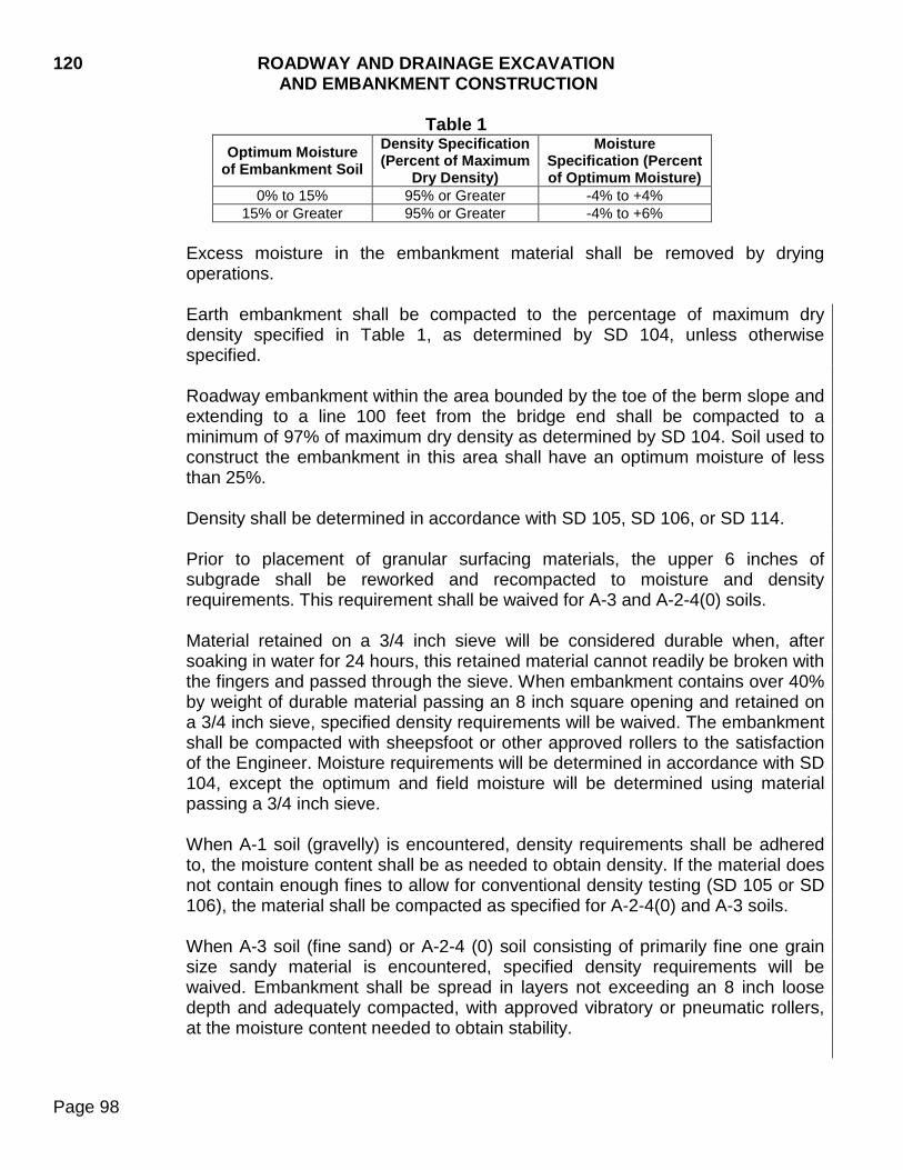
120 ROADWAY AND DRAINAGE EXCAVATION AND EMBANKMENT CONSTRUCTION
Page 98
Table 1 Optimum Moisture
of Embankment Soil Density Specification (Percent of Maximum
Dry Density)
Moisture Specification (Percent of Optimum Moisture)
0% to 15% 95% or Greater -4% to +4% 15% or Greater 95% or Greater -4% to +6%
Excess moisture in the embankment material shall be removed by drying operations. Earth embankment shall be compacted to the percentage of maximum dry density specified in Table 1, as determined by SD 104, unless otherwise specified. Roadway embankment within the area bounded by the toe of the berm slope and extending to a line 100 feet from the bridge end shall be compacted to a minimum of 97% of maximum dry density as determined by SD 104. Soil used to construct the embankment in this area shall have an optimum moisture of less than 25%. Density shall be determined in accordance with SD 105, SD 106, or SD 114. Prior to placement of granular surfacing materials, the upper 6 inches of subgrade shall be reworked and recompacted to moisture and density requirements. This requirement shall be waived for A-3 and A-2-4(0) soils. Material retained on a 3/4 inch sieve will be considered durable when, after soaking in water for 24 hours, this retained material cannot readily be broken with the fingers and passed through the sieve. When embankment contains over 40% by weight of durable material passing an 8 inch square opening and retained on a 3/4 inch sieve, specified density requirements will be waived. The embankment shall be compacted with sheepsfoot or other approved rollers to the satisfaction of the Engineer. Moisture requirements will be determined in accordance with SD 104, except the optimum and field moisture will be determined using material passing a 3/4 inch sieve.
When A-1 soil (gravelly) is encountered, density requirements shall be adhered to, the moisture content shall be as needed to obtain density. If the material does not contain enough fines to allow for conventional density testing (SD 105 or SD 106), the material shall be compacted as specified for A-2-4(0) and A-3 soils.
When A-3 soil (fine sand) or A-2-4 (0) soil consisting of primarily fine one grain size sandy material is encountered, specified density requirements will be waived. Embankment shall be spread in layers not exceeding an 8 inch loose depth and adequately compacted, with approved vibratory or pneumatic rollers, at the moisture content needed to obtain stability.
ROADWAY AND DRAINAGE EXCAVATION 120 AND EMBANKMENT CONSTRUCTION
Page 99
b. Ordinary Compaction Method: Compaction may be accomplished with any type of equipment which will give uniform satisfactory results.
A rolling procedure shall be established which will produce densities conforming to Table 1 in Section 120.3 B.3.a, unless otherwise specified. Sufficient tests will be taken during establishment of the rolling procedure to ensure that the required density is being obtained. Changes in material composition, moisture content, or compaction equipment may require that changes be made to the established rolling procedure. Soils shall be compacted within the moisture specification range in Table 1 in Section 120.3 B.3.a, unless otherwise specified. The moisture range will be established during the above rolling procedure. Visual confirmation of moisture content will be sufficient after the rolling procedure testing is completed. Excess moisture in the embankment material shall be removed by drying operations. The drying under such circumstances shall be carried on until the moisture content is such that the required density can be attained. Each layer shall be satisfactorily compacted before the next layer is placed. Compaction shall be extended to cover the subgrade width in completed cut sections under the same requirements, without additional compensation. Cut sections excavated below grade and refilled with the removed excavation or with selected soils shall be compacted in the same manner as embankments.
C. Select Subgrade Topping: The Contractor shall develop a plan, which demonstrates
that an adequate quantity of the designated material will be salvaged or reserved for select subgrade topping. It will be the responsibility of the Contractor to follow the established grading plan to the extent that an adequate quantity of material for select subgrade topping will be conserved for use. The surface upon which the select subgrade topping will be placed shall be constructed to within ±0.2 foot of the required elevation. Compaction of select subgrade topping shall be by the specified density method.
D. Waste and Surplus Excavation: Surplus excavation and waste material shall be disposed of as specified or as ordered by the Engineer.
Excess or unsuitable excavated material, including rock and boulders, that cannot be used in embankments may be placed on the side slopes of the nearest fill and placed to maintain a distinct shoulder line. Waste material shall be placed the maximum distance possible and at least 1 foot outside and 2 feet below the finished shoulder elevation.
Excavated material which contains bentonite shall be placed in that portion of an embankment section which is more than 20 feet below the finished subgrade surface, in embankment slopes which are outside the subgrade shoulder line, or in designated waste areas. During placement of this material in the embankment, the thickness of the total placement in any one area shall be as directed.
120 ROADWAY AND DRAINAGE EXCAVATION AND EMBANKMENT CONSTRUCTION
Page 100
E. Unclassified Excavation, Digouts: When granular material is used for backfill, the
excavated area shall extend to a daylight point so that lateral drainage is provided. The exposed undercut surface shall be compacted prior to backfilling. The existing gravel shall be salvaged before and replaced after the unstable material has been removed.
F. Option Borrow Excavation: Suitable materials removed from optioned borrow sources
shall be used in the embankments. Optioned borrow sources shall be graded to a neat and sightly appearance in accordance with grades, slopes, and requirements of the option agreement and to permit accurate measurement of quantities.
G. Borrow Excavation: Suitable materials removed from borrow sources shall be used in
the embankments. Borrow sources shall be graded to a neat and sightly appearance in accordance with grades, slopes, and requirements of the plans and to permit accurate measurement of quantities.
H. Water: Sufficient equipment shall be available to apply the quantity of water required to
secure the proper compaction before evaporation, absorption, or drainage prevents or interferes with the specified results. Moisture content of material shall be uniform for the full depth and extent of each layer.
I. Pit Run: Pit run material shall be compacted to 95% or greater of maximum dry density
as determined by the specified density method in layers not exceeding 8 inches loose depth. If the material does not contain enough fines to allow for conventional density testing (SD 105 or SD 106), the material shall be compacted as specified for A-2-4(0) and A-3 soils.
120.4 METHOD OF MEASUREMENT
A. Excavation: Excavation will be measured to the nearest cubic yard. Measurement of excavation will include unsuitable material excavated and removed to obtain proper compaction in cut sections and in foundations for fill sections. Suitable material temporarily removed and replaced to facilitate compaction, except undercutting required in Section 120.3 A.3, second paragraph, will not be measured for payment.
Accepted quantities of excavation will be measured in its original position by cross sectioning. The area excavated will include overbreakage or slides not due to carelessness of the Contractor. Where it is impractical to measure material by this method, acceptable methods involving three dimensional measurements or measurement in the hauling vehicle may be used. With written agreement between the Contractor and the Department, excavation which conforms to the staked lines and grades may be computed using original cross sections and staked sections. When specified, plan quantity will be the measurement for payment, provided the project is constructed to the lines and grades specified. Measurements will not be made except those necessary to determine that the work has been performed in conformance
ROADWAY AND DRAINAGE EXCAVATION 120 AND EMBANKMENT CONSTRUCTION
Page 101
with the plans or to measure changes which increase or decrease quantities. Such areas will be measured, differences in quantities computed and deductions or additions made. When no provisions exist for payment on a contract quantity basis, final settlement may be made on a contract quantity basis provided a written agreement between the Contractor and the Department is executed prior to final measurement. Unclassified excavation to be performed in connection with box culvert construction will be limited to that within the right-of-way limits. The quantity for this unclassified excavation will be plans quantity except as otherwise specified.
B. Embankment: Measurement of embankments will not be made. C. Select Subgrade Topping: Measurement will be by plan quantity. Quantities will be
based on computed embankment volume plus shrinkage. If changes in plan dimensions or locations are authorized, the final quantity will be determined by the as constructed volume using the shrinkage factor shown on the plans for the particular area of work. Final field measurement will not be made except that required to determine that the work was completed in accordance with plans and to document changes.
Material used for construction of the select subgrade topping will also be measured as unclassified excavation.
D. Waste: This work will not be measured, but shall be subsidiary work pertaining to the
several classes of excavation.
E. Option Borrow Excavation: Option borrow excavation will be measured in its original position by cross sectioning. Volumes will be computed in cubic yards.
Original cross sections will be taken prior to removal of any material and final cross sections will be taken following replacement of topsoil. Salvaged topsoil from the optioned borrow sources will be included as option borrow excavation.
The quantity of topsoil stockpiled and respread on optioned borrow sources will be determined by measuring the stockpiles prior to removal of the material from the stockpiles.
F. Contractor Furnished Borrow Excavation: Contractor furnished borrow excavation
will be measured in its original position by cross sectioning. Volumes will be computed in cubic yards.
Original cross sections will be taken prior to removal of any material and final cross sections will be taken following replacement of topsoil. Salvaged topsoil will not be measured.
G. Borrow Unclassified Excavation: Borrow unclassified excavation will be measured in
its original position by cross sectioning. Volumes will be computed in cubic yards.
120 ROADWAY AND DRAINAGE EXCAVATION AND EMBANKMENT CONSTRUCTION
Page 102
Original cross sections will be taken prior to removal of any material and final cross sections will be taken following replacement of topsoil. Salvaged topsoil stockpiled from the borrow sources will be included as borrow unclassified excavation.
The quantity of topsoil stockpiled and respread on borrow sources will be determined by measuring the stockpiles prior to removal of the material from the stockpiles.
H. Haul: Measurement of authorized haul will be made based on material being taken from excavation and hauled the shortest distance possible. The haul distance for material moved from outside the roadway will be measured along the shortest satisfactory route. The haul distance for material obtained from the roadway and placed inside the roadway shall be measured along the centerline of the roadway.
Haul shall be the product obtained by multiplying the number of units of excavation removed from its original position by the mean distance hauled. The distance between the center of gravity of the excavation and the center of gravity of the embankment shall be the haul distance.
I. Water: Water will be measured by the thousand gallon (MGal.) to the nearest 0.1 MGal.
Measurement will be by use of calibrated tanks or an approved water metering device which records in gallons.
Prior to using any water metering device the Contractor shall furnish a certified statement that such device conforms to AWWA requirements. The statement shall show that the device has been calibrated within the past year. Should subsequent measurements prove the measurements are unreliable another certified device producing satisfactory measurements shall be furnished. The head of each device shall be sealed when calibrated and the absence of such seal shall be cause to prohibit its use.
J. Pit Run: Pit Run will be measured to the nearest 0.1 ton. Water and materials which are paid for under separate items will not be measured under this item.
120.5 BASIS OF PAYMENT
A. Excavation: Completed and accepted work will be paid for at the contract unit price per cubic yard for the class of excavation involved. Payment will be full compensation for excavation; construction and compaction of cuts and embankments; shaping of slopes; finishing of surface; disposal of surplus materials; completion of subgrade, shoulders, and roadway; and maintenance. Scarifying, shaping, and recompacting as required under Section 120.3 A.3 shall be incidental to the unit price bid for excavation. Separate payment will not be made. 1. Unclassified Excavation: Excavation will be paid for at the contract unit price for
unclassified excavation unless contract items provide for other classes of excavation.
ROADWAY AND DRAINAGE EXCAVATION 120 AND EMBANKMENT CONSTRUCTION
Page 103
When no bid item or other mention of rock is shown in the contract and rock is encountered that requires blasting to excavate, such rock excavation will be paid for as per Section 9.5. Notification shall be given far enough in advance to ascertain the extent and nature of the rock formation before removal is begun. Payment as rock excavation will not be made unless notification is given.
2. Unclassified/Rock Excavation: Unclassified/rock excavation will be paid for at the contract unit price for unclassified/rock excavation.
3. Rock Excavation: When an item for rock excavation is provided, payment will be
made at the contract unit price. 4. Muck Excavation: When an item for muck excavation is provided, payment will be
made at the contract unit price. 5. Unclassified Excavation, Digouts: When an item for unclassified excavation,
digout is provided, payment will be made at the contract unit price.
6. Undercutting: Undercutting as described in Section 120.3 A.3 with corrections made for portions not accomplished and for portions not shown in the plans but ordered by the Engineer will be paid for at the contract unit price. Payment will be full compensation for work over and above that normally required for unclassified excavation.
B. Embankment: Embankment will not be paid for directly, but shall be subsidiary work
pertaining to the several classes of excavation.
C. Select Subgrade Topping: Select subgrade topping will be paid for at the contract unit price per cubic yard. Payment will be full compensation for work over and above that normally required for embankment construction.
D. Waste: Waste will not be paid for directly, but shall be subsidiary work pertaining to the
several classes of excavation.
E. Option Borrow Excavation: Option borrow excavation will be paid for at the contract unit price per cubic yard. Payment will be full compensation for excavation and furnishing the material on the project; construction and compaction of embankments; shaping of slopes; finishing of surface; completion of subgrade, shoulders, and roadway; maintenance; and for furnishing materials (except topsoil), labor, and incidentals required for restoration of the pit.
Topsoil stockpiled from the option borrow source will be respread and paid for at the contract unit price per cubic yard of option borrow excavation and placing topsoil. When the Contractor uses a pit not designated on the plans, the payment for topsoil, seeding, fertilizing, and mulching shall be plans quantity of the pit designated on the plans.
120 ROADWAY AND DRAINAGE EXCAVATION AND EMBANKMENT CONSTRUCTION
Page 104
F. Contractor Furnished Borrow Excavation: Contractor furnished borrow excavation
will be paid for at the contract unit price per cubic yard. Payment will be full compensation for excavation and furnishing the material on the project; construction and compaction of embankments; shaping of slopes; finishing of surface; completion of subgrade, shoulders, and roadway; maintenance, and for furnishing materials, labor, and incidentals required for restoration of the pit. Topsoil, seed, fertilizer, and mulch for the restoration of the pit shall be incidental to the unit price per cubic yard of Contractor furnished borrow excavation.
G. Borrow Unclassified Excavation: Borrow unclassified excavation will be paid for at
the contract unit price per cubic yard. Payment will be full compensation for excavation and furnishing the material on the project; construction and compaction of embankments; shaping of slopes; finishing of surface; completion of subgrade, shoulders, and roadway; maintenance; and for furnishing materials (except topsoil), labor, and incidentals required for restoration of the pit.
Topsoil stockpiled from the borrow source will be respread and paid for at the contract unit price per cubic yard of borrow unclassified excavation and placing topsoil.
H. Haul: This work will not be paid for directly, but shall be subsidiary work pertaining to the several classes of excavation. When, through no fault of the Contractor, changes cause an increase in the necessary haul, the resulting additional haul (total length of haul less average plan shown haul for the entire project) will be paid at the price established in the Special Provision for Price Schedule for Miscellaneous Items.
I. Water: Water will be paid for at the contract unit price per thousand gallons (MGal).
J. Pit Run: Pit Run will be paid for at the contract unit price per ton. Payment will be full
compensation for furnishing and placing materials, labor, equipment, and all incidentals required.
DUST CONTROL 205
Page 105
205.1 DESCRIPTION
This work shall consist of the application of a magnesium chloride solution or a calcium chloride solution to a prepared surface for dust control.
205.2 MATERIALS
Dust control materials shall conform to Section 891. 205.3 CONSTRUCTION REQUIREMENTS
Dust control chlorides shall be uniformly applied under pressure in liquid form by mechanical equipment. The equipment must be such that the application rate can be set, determined, and changed as required.
The rate of application shall be 1.2 pounds per square yard of surfacing. This weight shall be the anhydrous weight of calcium chloride or magnesium chloride in the solution as determined from the Certificate of Compliance. The material may be applied in one or two applications. The dust control material shall be blended into the top 1 to 2 inches of the gravel surfacing. The addition of water may be necessary to adequately compact the material. Rolling will be required as determined by the Engineer.
Additional applications or spot applications may be necessary to maintain dust control.
205.4 METHOD OF MEASUREMENT
A. Dust Control Chlorides: Calcium chloride and magnesium chloride will be measured by the anhydrous weight in pounds. The weight of anhydrous material will be based on the actual concentration to the nearest 0.1% as determined by the Department’s Materials & Surfacing Central Laboratory and the actual weight of the solution applied.
B. Water: Water will be measured as specified in Section 120.4.
205.5 BASIS OF PAYMENT
A. Dust Control Chlorides: Dust control chlorides will be paid for at the contract unit price per pound. Payment shall be full compensation for all equipment, labor, tools, materials, and incidentals necessary to complete the work.
B. Water: Water will be paid for as specified in Section 120.5.

205 DUST CONTROL
Page 106
THIS PAGE INTENTIONALLY LEFT BLANK

ROADWAY SHAPING 210
Page 107
210.1 DESCRIPTION
This work consists of reshaping an existing surface prior to placement of surfacing material.
210.2 MATERIALS (Not Specified) 210.3 CONSTRUCTION REQUIREMENTS
This work shall be performed in advance of placement of surfacing material. It shall be the Contractor's responsibility to maintain the prepared surface until surfacing has been placed.
A. Surface Preparation: The upper 4 inches of granular material shall be scarified,
reworked, shaped, and recompacted to the typical section in accordance with Section 260.3 C.
B. Ordinary Roadway Shaping: The existing granular material shall be removed and the
upper 6 inches of the subgrade shall be reworked and recompacted in accordance with Section 120.3 B.3.a. After the subgrade is reworked and recompacted, the granular material shall be brought back onto the roadway and recompacted in accordance with Section 260.3 D.
On newly constructed earth subgrades, the upper 6 inches of the subgrade shall be reworked and recompacted in accordance with Section 120.3 B.3.a prior to placing granular materials. This requirement shall be waived for A-3 and A-2-4(0) soils.
C. Heavy Roadway Shaping: The existing granular material shall be removed and upper
12 inches of the subgrade shall be reworked and recompacted in a minimum of two lifts in accordance with Section 120.3 B.3.a. The Engineer may order the Contractor to rework and recompact the subgrade to a depth greater than 12 inches. If more than 12 inches of the subgrade is reworked and recompacted, the maximum lift thickness during recompaction shall not exceed 6 inches. After the subgrade is reworked and recompacted, the granular material shall be brought back onto the roadway and recompacted in accordance with Section 260.3 D.
On newly constructed earth subgrades, the upper 12 inches of the subgrade shall be reworked and recompacted in accordance with Section 120.3 B.3.a prior to placing granular materials. This requirement shall be waived for A-3 and A-2-4(0) soils.
D. Unclassified Excavation, Digouts: Unclassified excavation, digouts consists of the removal and disposal of unstable material below the required depth of surface preparation, ordinary roadway shaping, or heavy roadway shaping on which surfacing material is to be placed. If unstable material is encountered the Contractor shall excavate unstable material. When granular material is used for backfill, the excavated area shall extend to a daylight point so lateral drainage is provided. The exposed undercut surface shall be satisfactorily compacted prior to backfilling. Backfill shall be placed and compacted as directed by the Engineer.
210 ROADWAY SHAPING
Page 108
The subgrade shall be finished to within minus 0.04 feet to plus 0.08 feet from the design grade and typical section shown in the plans and to within ±0.5% of the typical section cross slope. The quarter crown within any 12 foot transverse length shall not exceed 0.04 feet when measured with a straight edge, stringline, or by other suitable equipment. Following roadway shaping, the centerline shall be finished to a transverse distance within ± 0.25 feet of the plans shown location of centerline. Following surface preparation, the centerline shall be finished to a transverse distance within ± 0.1 foot of the plans shown location of centerline.
Water shall be furnished by the Contractor in accordance with Section 120.
210.4 METHOD OF MEASUREMENT
A. Surface Preparation, Ordinary Roadway Shaping, and Heavy Roadway Shaping: Surface preparation, ordinary roadway shaping, and heavy roadway shaping will be measured to the nearest 0.001 mile, along the centerline of the project. If additional heavy roadway shaping is required, the quantity of heavy roadway shaping will be proportionately increased by the same percentage increase in required depth. (For example, heavy roadway shaping to a depth of 18 inches will be equivalent to 1.5 times the quantity of the standard heavy roadway shaping.)
On projects involving more than one mainline roadbed each roadbed will be measured, based on the project centerline. When a project centerline is not provided, measurement of each roadbed will be based on its construction centerline. Measurement of access roads for rest areas and weigh stations, cross roads, ramps, and service roads will be based on construction lines. The points where measurement will begin and end will be as shown.
B. Unclassified Excavation, Digouts: Excavation of unstable material will be measured as set forth in Section 120.4.
C. Water: Water will be measured in accordance with Section 120.4. Granular material, other than existing surface gravel, used to backfill digouts will be measured to the nearest 0.1 ton.
210.5 BASIS OF PAYMENT
A. Surface Preparation: Surface preparation will be paid for at the contract unit price per mile. Payment will be full compensation for scarifying, reworking, shaping, compacting, reprocessing blotters if required, equipment, labor, and incidentals necessary to satisfactorily complete the work.
B. Ordinary Roadway Shaping and Heavy Roadway Shaping: Ordinary roadway
shaping and heavy roadway shaping will be paid for at the contract unit price per mile. Payment will be full compensation for equipment, labor, and incidentals necessary to
ROADWAY SHAPING 210
Page 109
satisfactorily remove the existing surfacing, shape, replace, and compact the materials as specified.
C. Unclassified Excavation, Digouts: Unclassified excavation, digouts will be paid for as
per Section 120.5.
D. Water: Water will be paid for in accordance with Section 120.5.
Granular material used to backfill digouts will be paid for at the contract unit price per ton. The contract unit price shall include all costs associated with furnishing, hauling, placing, and compacting the material.

210 ROADWAY SHAPING
Page 110
THIS PAGE INTENTIONALLY LEFT BLANK
SALVAGING, STOCKPILING, AND PLACING TOPSOIL 230
Page 111
230.1 DESCRIPTION This work consists of excavating, hauling, stockpiling, depositing, and spreading topsoil on prepared areas.
230.2 MATERIALS (Not specified) 230.3 CONSTRUCTION REQUIREMENTS
A. Salvage: Topsoil shall be selected from the regular grading areas or from other designated areas.
Areas from which topsoil is to be excavated shall be cleared of objectionable vegetation and all litter such as brush, rock, and foreign material. Topsoil shall be excavated in sufficient volume to cover the designated areas to the required depths.
Salvaged topsoil may be stockpiled in convenient locations within the right-of-way as approved by the Engineer. The separation of cut and fill piles is not required. Topsoil piles shall be located where the topsoil will not run off into any waterway due to a rain event.
When operations of the Contractor do not permit stockpiling of topsoil within the right-of-way, it shall be the Contractor's obligation to arrange for stockpile sites at the Contractor’s own expense. The stockpiles shall be shaped and smoothed to permit accurate measurements. Stockpile areas shall be left in a neat condition.
B. Preparation of Roadway: Areas designated to be covered with salvaged topsoil shall
be undercut or underfilled so the finished lines conform to the template lines on the cross sections after the topsoil placement. The areas receiving topsoil shall be shaped and smoothed prior to placing topsoil.
C. Placing: Topsoil shall be spread evenly and uniformly over the designated areas to the
specified depth. If topsoil is not available in sufficient quantities to cover the designated areas to the plan specified depth, the Contractor shall spread the available topsoil as required by the Engineer.
230.4 METHOD OF MEASUREMENT
A. Salvaged Topsoil: Measurement for removal of topsoil from its original position will be made in cubic yards. Measurement will not be made unless such removal is designated on the plans or directed by the Engineer. The volume of topsoil will be determined by measuring the topsoil stockpiles.
B. Placing Topsoil: The cubic yards of topsoil to be measured shall be the quantity of
topsoil removed from stockpiles and placed on the designated areas. Measurements will be made prior to removal of the material from such stockpiles.
230 SALVAGING, STOCKPILING AND PLACING TOPSOIL
Page 112
230.5 BASIS OF PAYMENT
A. Salvaged Topsoil: Topsoil salvaged from Contractor furnished borrow sources will be incidental to the contract unit price per cubic yard for contractor furnished borrow excavation. Topsoil salvaged from option borrow sources will be paid for at the contract unit price per cubic yard for option borrow excavation. Topsoil salvaged from designated borrow sources will be paid for at the contract unit price per cubic yard for borrow unclassified excavation. All other topsoil will be paid for at the contract unit price per cubic yard for unclassified excavation. The amount of topsoil that has been added to the option borrow excavation, borrow unclassified excavation, and unclassified excavation quantity will be indicated on the plans. The payment will be full compensation for excavation (which includes necessary undercutting to provide space for topsoil placement) and stockpiling.
Separate payment will not be made for haul under this item.
B. Placing Topsoil: The placement of salvaged topsoil will be paid for at the contract unit
price per cubic yard for placing topsoil. Topsoil placed on Contractor furnished borrow sources will be incidental to the contract unit price per cubic yard for contractor furnished borrow excavation.
This payment shall be full compensation for labor, equipment, tools, and incidentals necessary for removing topsoil from stockpiles, hauling, depositing, spreading, and finishing of topsoil.
Separate payment will not be made for haul under this item.
OBLITERATING OLD ROADS 240
Page 113
240.1 DESCRIPTION This work consists of scarifying, plowing, grading, and harrowing of abandoned roads outside the limits of the new construction.
240.2 MATERIALS (Not Specified) 240.3 CONSTRUCTION REQUIREMENTS
After opening the new road to traffic the portion of the road to be obliterated shall be graded to a contour which will blend with the contour of the adjoining land.
Obliteration and removal shall include flattening the backslopes and embankment slopes so farm cultivation work could be done to the satisfaction of the Engineer. Portions of the obliterated road surface to be covered with less than 1 foot of earth shall be scarified to a depth of not less than 6 inches.
In areas of rock or rough topography not adaptable to cultivation, the desired obliteration and disposal will be detailed on the plans.
240.4 METHOD OF MEASUREMENT
The item of obliterating old roads will be measured to the nearest station of 100 feet along the centerline of the old road.
240.5 BASIS OF PAYMENT
Payment for obliterating old roads will be made at the contract unit price per station inclusive of all labor and equipment required.

240 OBLITERATING OLD ROADS
Page 114
THIS PAGE INTENTIONALLY LEFT BLANK

INCIDENTAL WORK 250
Page 115
250.1 DESCRIPTION This work includes all incidental items listed in the contract which must be performed to complete the contract.
250.2 MATERIALS (Not Specified)
250.3 CONSTRUCTION REQUIREMENTS
Incidental work will be listed in detail in the plans. This work shall be performed in a skillful manner to properly facilitate the whole of the work and as directed.
250.4 METHOD OF MEASUREMENT
Field measurement for the item of incidental work will not be required. 250.5 BASIS OF PAYMENT
Incidental work will be paid for at the contract lump sum price unless changes in work are ordered by the Engineer. Payment will be full compensation for labor, equipment, and materials necessary to complete the work.

250 INCIDENTAL WORK
Page 116
THIS PAGE INTENTIONALLY LEFT BLANK
PART B GRANULAR BASES AND SURFACING 260 GRANULAR BASES AND SURFACING
Page 117
260.1 DESCRIPTION This work consists of providing one or more courses of aggregate on a prepared surface.
260.2 MATERIALS A. Subbase, Base Course, Gravel Cushion, and Gravel Surfacing shall conform to
Section 882. Granular additives, including but not limited to, sand and rock may be necessary to produce material of the type specified.
B. Clay Binder, when required for gravel surfacing, shall conform to Section 883. C. Subbase, Salvaged; Base Course, Salvaged; Gravel Cushion, Salvaged; and
Gravel Surfacing, Salvaged shall conform to Section 884. 260.3 CONSTRUCTION REQUIREMENTS
A. General Requirements: The following processing descriptions shall apply to this work:
Road Mix Method - Prior to placement, the Contractor shall windrow and equalize the materials, including water, to the satisfaction of the Engineer. The Contractor shall use a blade or other suitable equipment to spread the materials. The Contractor shall windrow granular materials dumped on the prepared surface prior to incorporating additives. Central Plant Mix Method - Prior to placement, the Contractor shall process and uniformly feed materials, including water, into the mixer at a predetermined rate. The plant shall be equipped with positive proportioning devices and shall thoroughly mix the materials.
Processed granular material shall be placed in accordance with the following requirements. 1. Mainline: Granular material placed on the mainline portion of the roadway shall be
processed by either road mix method or central plant mix method. When the material is laid by a spreader, the material shall have been previously processed by the central plant mix method. The material placed shall be limited to the quantity necessary to construct a maximum of a 4 inch compacted layer.

260 GRANULAR BASES AND SURFACING
Page 118
2. Shoulders: Granular material placed on the shoulder portion of the roadway shall be processed and placed in accordance with the following: a. Adjacent to PCC Pavement: Granular material placed adjacent to Portland
cement concrete pavement shall be processed by the central plant mix method and placed with a spreader approved by the Engineer. The material placed shall be limited to the quantity necessary to construct a maximum of a 4 inch compacted layer.
b. Adjacent to AC Pavement: Granular material placed adjacent to asphalt concrete pavement shall be processed and placed by one of the following methods: 1) Granular material shall be processed by the central plant mix method and
placed with a spreader approved by the Engineer. The material placed shall be limited to the quantity necessary to construct a maximum of a 4 inch compacted layer.
2) Granular material shall be placed on the shoulder and processed by the road
mixed method. The material placed shall be limited to the quantity necessary to construct a maximum of a 2 inch compacted layer.
When granular material is placed on the shoulder and the final finished surface is to remain granular surface next to either PCC pavement or AC pavement, the Contractor may use either of the methods described in 260.3 A.2.b.
The granular material shall be spread evenly to the specified width. Watering shall be accomplished during the spreading operation. The final rolling of the top surface of the granular material shall embed as many loose stones as possible. The finished surface shall be smooth and free from waves and the Contractor shall finish the surfacing materials to within ±0.5% of the typical section cross slope. The quarter crown within any 12 foot transverse length (or actual lane width paved with a single paver pass) shall not exceed 0.04 feet when measured with a straight edge, stringline, or other suitable equipment. The centerline shall be finished to a transverse distance within ± 0.25 feet of the plans shown location of centerline. Granular material used for backfilling unclassified excavation digouts, intersecting roads, and entrances shall be compacted to the satisfaction of the Engineer. RCA shall not be used in areas where drainage fabric, edge drains, or other similar drainage systems are present except RCA will be allowed where approach drains and transverse drains are present.
GRANULAR BASES AND SURFACING 260
Page 119
B. Subbase and Base Course: Each layer shall be compacted to the specified density before the next lift is placed and shall be rolled until a uniform and stable surface is obtained. Subbase shall be compacted to 95% of the maximum dry density. Base Course shall be compacted to 97% of the maximum dry density. The maximum dry density will be determined by SD 104 Method 4. The percent of the maximum dry density will be determined by SD 105, SD 110, or SD 114.
C. Subbase, Salvaged and Base Course, Salvaged: Compaction and density requirements shall be a minimum of 95% of the target dry density established by SD 219 and compacted under the following conditions: 1. Material shall have a minimum of 4% moisture uniformly blended throughout the
depth of the lift of material. The percent moisture may be adjusted by the Engineer.
2. A minimum of 1 test strip for each lift placed shall be completed to determine the target dry density and optimum rolling sequence. The test strips will remain in place as part of the completed work.
3. The depth of the test strip lift shall be representative of the project. 4. When there is a significant change in mix proportions, weather conditions,
equipment, or other controlling factors, the Engineer may require construction of another test strip to check target density.
5. Pneumatic tired rollers shall have an effective roller weight of at least 250 pounds
per inch of roller width or satisfactory vibratory compaction equipment. Tires shall be uniformly inflated so their air pressures will not vary by more than 5 psi. Rollers shall be operated with tire pressures and wheel loads within the manufacturer’s recommended range for the size and ply of the tire being used.
Steel face rollers shall furnish a minimum rolling weight of 275 pounds per inch of rolling width.
D. Gravel Cushion and Gravel Cushion, Salvaged: Compaction to a specified density is
not required. Rolling shall proceed simultaneously with the spreading and watering and continue in overlapping strips until a uniform, stable surface is obtained.
Pneumatic tired rollers shall have an effective roller weight of at least 250 pounds per inch of roller width or satisfactory vibratory compaction equipment. Tires shall be uniformly inflated so their air pressures will not vary by more than 5 psi. Rollers shall be operated with tire pressures and wheel loads within the manufacturer’s recommended range for the size and ply of the tire being used.
260 GRANULAR BASES AND SURFACING
Page 120
Steel face rollers shall furnish a minimum rolling weight of 275 pounds per inch of rolling width.
E. Gravel Surfacing and Gravel Surfacing, Salvaged: Compaction to a specified density is not required. Rolling shall proceed simultaneously with the spreading and watering and continue in overlapping strips until a uniform, stable surface is obtained. Pneumatic tired rollers shall have an effective roller weight of at least 250 pounds per inch of roller width or satisfactory vibratory compaction equipment. Tires shall be uniformly inflated so their air pressures will not vary by more than 5 psi. Rollers shall be operated with tire pressures and wheel loads within the manufacturer’s recommended range for the size and ply of the tire being used. Steel face rollers shall furnish a minimum rolling weight of 275 pounds per inch of rolling width.
260.4 METHOD OF MEASUREMENT
Subbase; Subbase, Salvaged; Base Course; Base Course, Salvaged; Gravel Cushion; Gravel Cushion, Salvaged; Gravel Surfacing (including clay binder); and Gravel Surfacing, Salvaged will be measured to the nearest 0.1 ton. The Contractor shall replace material lost or wasted during the processing operation at no additional expense to the Department. Material placed in excess of the quantity needed to construct the typical section will be deducted from the final measured quantity. Water added during crushing and water mixed with granular material by a central plant will not be measured and the weight will not be subtracted from the granular material. Water for granular material, added during laydown operations, and materials which are paid for under separate items will not be measured under these items.
260.5 BASIS OF PAYMENT
Subbase; Subbase, Salvaged; Base Course; Base Course, Salvaged; Gravel Cushion; Gravel Cushion, Salvaged; Gravel Surfacing (including clay binder); and Gravel Surfacing, Salvaged will be paid for at the contract unit price per ton. Payment will be full compensation for furnishing and placing materials, water added in a central plant, labor, equipment, test strips (if required), and all incidentals required.
If roadway shaping is required, and a bid item is not provided, payment for the granular material items will be full compensation for necessary shaping work.
SALVAGING, PROCESSING, AND STOCKPILING GRANULAR 270 BASE AND ASPHALT CONCRETE MIX MATERIALS
Page 121
270.1 DESCRIPTION
This work consists of salvaging, processing, blending, crushing, and stockpiling salvaged material from the existing roadway. Salvaged material shall consist of granular material, asphalt concrete mix material, or asphalt mix and granular base material.
270.2 MATERIALS
Salvaged material shall meet the requirements of Section 884. 270.3 CONSTRUCTION REQUIREMENTS
A. General: The Contractor shall not dispose of salvaged material or use the salvaged material for any purpose other than purposes designated in the plans without approval by the Engineer.
B. Salvage and Stockpile Granular Material or Salvage and Stockpile Asphalt mix
and Granular Base Material:
1. Salvaging: The salvaged material shall be removed and loaded in a manner that minimizes waste and avoids contamination of the salvage material with underlying subgrade soil. Scrapers shall not be used for the removing or loading operations, but may be used to haul the material. Salvaging of material shall not exceed 2 miles in advance of the grading operation. Salvaging of material may extend to 3 miles in advance of the grading operation if approved by the Engineer. The Engineer will only approve the request if the Contractor can demonstrate that the additional distance is necessary for the grading operation and that sufficient access is provided at intersecting roads and driveways. The material shall be moved toward the center of the road, to the extent necessary to ensure that salvage material is not lost down inslopes.
2. Processing: Processing and blending may be accomplished in place, provided the
Contractor's method meets the blending and gradation requirements and has positive depth control.
3. Stockpiling: Asphalt concrete mix and granular material shall be processed or
crushed and stockpiled together so that a uniform blend is obtained. The salvaged material may be stockpiled at contractor provided sites. Prior to stockpiling, the stockpile site shall be prepared by removal of the top 6 inches of topsoil and the area bladed smooth.
C. Salvage and Stockpile Asphalt Mix Material:
1. Salvaging: The salvaged material shall be removed and loaded in a manner that minimizes waste and avoids contamination of the salvage material. Scrapers shall not be used for the removing or loading operations, but may be used to haul the material. Salvaging of material shall not exceed 2 miles in advance of the grading operation, unless otherwise directed. The material shall be moved toward the center
270 SALVAGING, PROCESSING, AND STOCKPILING GRANULAR BASE AND ASPHALT CONCRETE MIX MATERIALS
Page 122
of the road, to the extent necessary to ensure that salvage material is not lost down inslopes.
2. Stockpiling: Salvaged asphalt mix material shall be processed or crushed, and
stockpiled so a uniform blend is obtained. Prior to stockpiling, the stockpile site shall be prepared by removal of the top 6 inches of topsoil and the area bladed smooth. Stockpiles shall be constructed in accordance with Section 320.3 C. The stockpiles shall not contain dirt, grease, oil, brick, paving fabric, clay balls, organic debris, and other foreign material.
270.4 METHOD OF MEASUREMENT
Salvage and stockpile granular material, salvage and stockpile asphalt mix and granular base material, and salvage and stockpile asphalt mix material will be measured to the nearest 0.1 ton at the time it is hauled to the road.
When less than 5,000 tons of salvaged material is required on a project, the material may be measured in a stockpile and converted to tons using a factor of 1.50 tons per cubic yard, in lieu of weighing the material. Alternate measurement techniques may be allowed if agreed upon by the Contractor and Engineer prior to salvaging operations commencing.
Material stockpiled for future use will be measured in the stockpile and converted to tons using a factor of 1.50 tons per cubic yard. The unclassified excavation quantities will not be increased or decreased to reflect whether salvaged material was taken from cut or fill sections.
270.5 BASIS OF PAYMENT
Salvage and stockpile granular material, salvage and stockpile asphalt mix and granular base material, and salvage and stockpile asphalt mix material will be paid for at the contract unit price per ton. Payment will be full compensation for work required to salvage, haul, process or crush, and stockpile the material. Removal of this material is also included in and paid for once under the item of unclassified excavation.
FULL DEPTH RECLAMATION (FDR) 280
Page 123
280.1 DESCRIPTION
Full depth reclamation (FDR) shall consist of processing and blending the asphalt mix and granular base material and placing, watering, shaping, and compacting the material to the typical section.
280.2 MATERIALS
The asphalt mix and granular base material shall conform to Section 884.
280.3 CONSTRUCTION REQUIREMENTS
A. Equipment:
1. Recycling Equipment: The equipment shall be self propelled and capable of processing and blending the material to the depth specified in the plans.
2. Rollers: Pneumatic tired rollers shall have an effective roller weight of at least 250
pounds per inch of roller width or satisfactory vibratory compaction equipment. Tires shall be uniformly inflated so their air pressures will not vary by more than 5 psi. Rollers shall be operated with tire pressures and wheel loads within the manufacturer’s recommended range for the size and ply of the tire being used. Steel rollers shall furnish a minimum rolling weight of 275 pounds per inch of rolling width.
B. Processing and Laydown: Asphalt concrete mix and granular base material shall be
processed in place so that a uniform blend is obtained. The material shall be handled to ensure that salvaged material is not lost down the inslope. The processed material shall be placed in a minimum of two lifts. The maximum lift thickness shall not exceed 4 inches. The depths of the in place asphalt concrete and granular base material may vary from what is shown in the plans. The Contractor will be responsible for interpreting the depths and including all costs to process the required depth of existing pavement and granular material. Each layer shall be compacted to the required density before the next lift is placed and shall be rolled until a uniform, stable surface is obtained. The final rolling of the top surface of the granular materials shall embed as many loose stones as possible. The finished surface shall be smooth and free from waves and the Contractor shall finish the surfacing materials to within ±0.5% of the typical section cross slope. The quarter crown within any 12 foot transverse length (or actual lane width paved with a single paver pass) shall not exceed 0.04 feet when measured with a straight edge,
280 FULL DEPTH RECLAMATION (FDR)
Page 124
stringline, or other suitable equipment. The centerline shall be finished to a transverse distance within ± 0.25 feet of the plans shown location of centerline. The Contractor shall conduct his operations in such a way that both lanes will be brought up even at the end of each day.
C. Compaction and Density Requirements: Compaction and density requirements shall be a minimum of 95% of the target dry density established by SD 219 and compacted under the following conditions:
1. Material shall have a minimum of 4% moisture uniformly blended throughout the
depth of the lift of material. The percent moisture may be adjusted by the Engineer.
2. A minimum of 1 test strip for each lift placed shall be completed to determine the target dry density and optimum rolling sequence. The test strips will remain in place as part of the completed work.
3. The depth of the test strip lift shall be representative of the project.
4. When there is a significant change in mix proportions, weather conditions, equipment, or other controlling factors the Engineer may require construction of another test strip to check target density.
280.4 METHOD OF MEASUREMENT
FDR will be measured to the nearest square yard. Plans quantity will be the basis of payment, unless changes are ordered by the Engineer. Water and materials which are paid under separate items will not be measured under this item.
280.5 BASIS OF PAYMENT
FDR will be paid for at the contract price per square yard inclusive of all costs for processing, blending, placing, shaping, compacting, equipment, test strips, labor, and incidentals necessary to satisfactorily complete the work. Plans quantity will be the basis of payment, unless changes are ordered by the Engineer.
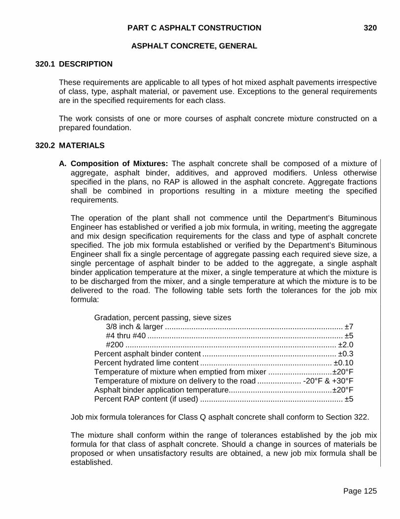
PART C ASPHALT CONSTRUCTION 320 ASPHALT CONCRETE, GENERAL
Page 125
320.1 DESCRIPTION These requirements are applicable to all types of hot mixed asphalt pavements irrespective of class, type, asphalt material, or pavement use. Exceptions to the general requirements are in the specified requirements for each class. The work consists of one or more courses of asphalt concrete mixture constructed on a prepared foundation.
320.2 MATERIALS A. Composition of Mixtures: The asphalt concrete shall be composed of a mixture of
aggregate, asphalt binder, additives, and approved modifiers. Unless otherwise specified in the plans, no RAP is allowed in the asphalt concrete. Aggregate fractions shall be combined in proportions resulting in a mixture meeting the specified requirements. The operation of the plant shall not commence until the Department’s Bituminous Engineer has established or verified a job mix formula, in writing, meeting the aggregate and mix design specification requirements for the class and type of asphalt concrete specified. The job mix formula established or verified by the Department’s Bituminous Engineer shall fix a single percentage of aggregate passing each required sieve size, a single percentage of asphalt binder to be added to the aggregate, a single asphalt binder application temperature at the mixer, a single temperature at which the mixture is to be discharged from the mixer, and a single temperature at which the mixture is to be delivered to the road. The following table sets forth the tolerances for the job mix formula:
Gradation, percent passing, sieve sizes 3/8 inch & larger ................................................................................. ±7 #4 thru #40 ......................................................................................... ±5 #200 ................................................................................................ ±2.0
Percent asphalt binder content ............................................................. ±0.3 Percent hydrated lime content ............................................................ ±0.10 Temperature of mixture when emptied from mixer ............................. ±20°F Temperature of mixture on delivery to the road .................... -20°F & +30°F Asphalt binder application temperature............................................... ±20°F Percent RAP content (if used) ................................................................. ±5
Job mix formula tolerances for Class Q asphalt concrete shall conform to Section 322. The mixture shall conform within the range of tolerances established by the job mix formula for that class of asphalt concrete. Should a change in sources of materials be proposed or when unsatisfactory results are obtained, a new job mix formula shall be established.
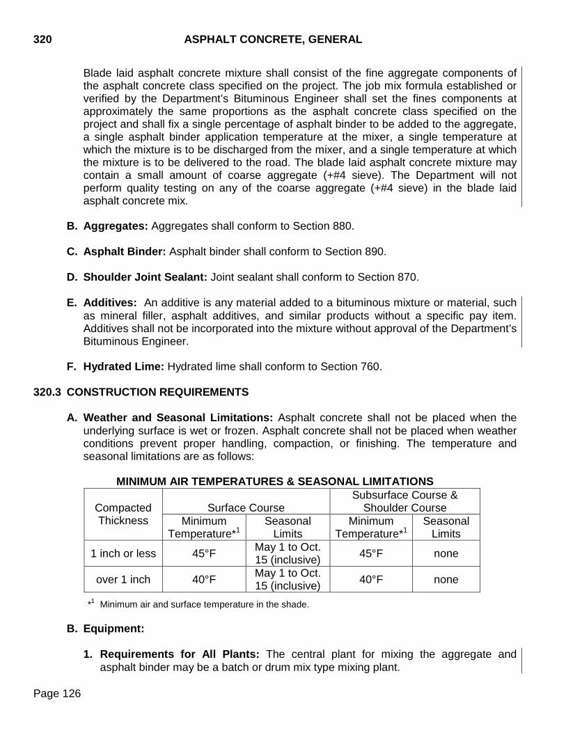
320 ASPHALT CONCRETE, GENERAL
Page 126
Blade laid asphalt concrete mixture shall consist of the fine aggregate components of the asphalt concrete class specified on the project. The job mix formula established or verified by the Department’s Bituminous Engineer shall set the fines components at approximately the same proportions as the asphalt concrete class specified on the project and shall fix a single percentage of asphalt binder to be added to the aggregate, a single asphalt binder application temperature at the mixer, a single temperature at which the mixture is to be discharged from the mixer, and a single temperature at which the mixture is to be delivered to the road. The blade laid asphalt concrete mixture may contain a small amount of coarse aggregate (+#4 sieve). The Department will not perform quality testing on any of the coarse aggregate (+#4 sieve) in the blade laid asphalt concrete mix.
B. Aggregates: Aggregates shall conform to Section 880. C. Asphalt Binder: Asphalt binder shall conform to Section 890. D. Shoulder Joint Sealant: Joint sealant shall conform to Section 870. E. Additives: An additive is any material added to a bituminous mixture or material, such
as mineral filler, asphalt additives, and similar products without a specific pay item. Additives shall not be incorporated into the mixture without approval of the Department’s Bituminous Engineer.
F. Hydrated Lime: Hydrated lime shall conform to Section 760.
320.3 CONSTRUCTION REQUIREMENTS
A. Weather and Seasonal Limitations: Asphalt concrete shall not be placed when the underlying surface is wet or frozen. Asphalt concrete shall not be placed when weather conditions prevent proper handling, compaction, or finishing. The temperature and seasonal limitations are as follows:
MINIMUM AIR TEMPERATURES & SEASONAL LIMITATIONS
Compacted Thickness
Surface Course
Subsurface Course & Shoulder Course
Minimum Temperature*1
Seasonal Limits
Minimum Temperature*1
Seasonal Limits
1 inch or less 45°F May 1 to Oct. 15 (inclusive) 45°F none
over 1 inch 40°F May 1 to Oct. 15 (inclusive) 40°F none
*1 Minimum air and surface temperature in the shade.
B. Equipment:
1. Requirements for All Plants: The central plant for mixing the aggregate and asphalt binder may be a batch or drum mix type mixing plant.
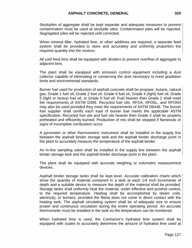
ASPHALT CONCRETE, GENERAL 320
Page 127
Stockpiles of aggregate shall be kept separate and adequate measures to prevent contamination must be used at stockpile sites. Contaminated piles will be rejected. Segregated piles will be rejected until corrected. When mineral filler, hydrated lime, or other additives are required, a separate feed system shall be provided to store and accurately and uniformly proportion the required quantity into the mixture. All cold feed bins shall be equipped with dividers to prevent overflow of aggregate to adjacent bins. The plant shall be equipped with emission control equipment including a dust collector capable of eliminating or conserving the dust necessary to meet gradation limits and environmental standards. Burner fuel used for production of asphalt concrete shall be propane, butane, natural gas, Grade 1 fuel oil, Grade 2 fuel oil, Grade 4 fuel oil, Grade 4 (light) fuel oil, Grade 5 (light or heavy) fuel oil, or Grade 6 fuel oil. Fuel heavier than Grade 2 shall meet the requirements of ASTM D396. Recycled fuel oils, RFO4, RFO5L, and RFO5H may also be used provided they meet the requirements of ASTM D6448. The burner fuel supplier shall certify each load of burner fuel meets the applicable ASTM specification. Recycled fuel oils and fuel oils heavier then Grade 2 shall be properly preheated and efficiently burned. Production of mix shall be stopped if flameouts or signs of incomplete combustion occur. A pyrometer or other thermometric instrument shall be installed in the supply line between the asphalt binder storage tank and the asphalt binder discharge point in the plant to accurately measure the temperature of the asphalt binder. An in-line sampling valve shall be installed in the supply line between the asphalt binder storage tank and the asphalt binder discharge point in the plant. The plant shall be equipped with accurate weighing or volumetric measurement devices. Asphalt binder storage tanks shall be kept level. Accurate calibration charts which show the quantity of material contained in a tank at each 1/4 inch increments of depth and a suitable device to measure the depth of the material shall be provided. Storage tanks shall uniformly heat the material, under effective and positive control, to the required temperature. Heating shall be accomplished by steam coils, electricity, or burners, provided the flame does not come in direct contact with the heating tank. The asphalt circulating system shall be of adequate size to ensure proper and continuous circulation during the entire operating period. An accurate thermometer must be installed in the tank so the temperature can be monitored. When hydrated lime is used, the Contractor’s hydrated lime system shall be equipped with scales to accurately determine the amount of hydrated lime used at
320 ASPHALT CONCRETE, GENERAL
Page 128
any time. The Contractor’s hydrated lime system shall control fugitive lime dust from being released into the air. Hydrated lime, when added, shall be added at the pugmill to moistened aggregate containing a minimum moisture content of 1.0% above the saturated surface dry condition of the aggregate, as noted on the approved job mix formula. The mixing of the aggregate, hydrated lime and water shall be accomplished by using an enclosed twin-shaft pugmill with a minimum effective length of 4.5 feet. A water spray system must be installed at the discharge end of the pug mill. This water system must be used when directed by the Engineer to prevent fugitive lime dust from being released into the air.
2. Batch Type Mixing Plants: Batch type plants shall have at least two storage bins with sufficient capacity to furnish the quantity of mineral aggregate materials necessary to operate at the calibrated capacity of the plant. Each compartment shall have partitions to prevent diversion of material into other compartments. Vibrators shall be provided to prevent bridging or arching of the bin contents.
Batch plants shall be fully automatic, to the extent the only manual operation required would be for the proportioning of one batch utilizing a single actuation switch or starter. The automatic unit shall include a timer to automatically control the measuring, mixing, and dumping processes through a central control. The automatic unit shall include a time lock device, capable of controlling the operations of a complete mixing cycle. When RAP is used, batch plants shall be modified to permit the RAP to feed directly into the weigh hopper of the plant. When RAP is used, the heated virgin aggregate shall be deposited in the weigh hopper first followed by the RAP. These two materials shall be “dry” mixed for a minimum of 10 seconds before introduction of asphalt binder into the pugmill. Wet mixing time shall be a minimum of 25 seconds. Mixing times may be adjusted by the Engineer, as necessary, to achieve uniform mixing and coating. Discharge of the heated virgin aggregate shall be from one bin only and shall be discharged into the center of the weigh hopper. The amount of aggregate stored in the bin shall not exceed one batch in weight and shall be fed into the bin in a manner that will prevent segregation. A recording pyrometer shall be mounted in the discharge chute of the dryer. Daily charts of continuous aggregate temperature readings shall be submitted to the Engineer. In lieu of a recording pyrometer, a computer printout showing the aggregate temperature readings at the discharge chute of the dryer may be substituted as approved by the Engineer.
3. Drum Mix Plants: The dryer drum shall uniformly heat, coat, and mix the materials without overheating the materials and adversely affecting the mixture.
ASPHALT CONCRETE, GENERAL 320
Page 129
a. Materials and additives, except RAP, shall be fed simultaneously into the dryer.
b. The aggregate and RAP feed system shall be easily and accurately calibrated
and shall provide positive control of the aggregate feed. The rate of feed shall be continuously monitored by belt scale or other device interlocked with the asphalt metering mechanism.
c. RAP, when used, shall be introduced into the drum and combined with the
aggregate so the RAP does not come into direct contact with the burner flame. Asphalt binder shall be added to the mixture in the drum after the aggregates and RAP have been combined.
d. The asphalt metering device shall positively control the rate asphalt is introduced into the mixture and shall respond instantaneously to variation in the aggregate feed rate.
e. Production shall be limited to the rate required to obtain uniform aggregate
coating and a uniform mixture meeting job mix temperature requirements. The rate must be within manufacturers rated plant capacity.
f. A recording pyrometer shall be mounted in the discharge end of the mixer for
determining the temperature of the mix. Daily charts of continuous mix temperature readings shall be submitted to the Engineer. In lieu of a recording pyrometer, a computer printout showing the mix temperature readings at the discharge end of the mixer may be substituted as approved by the Engineer.
4. Blade Laid Asphalt Concrete Equipment: The Contractor shall use either a motor
grader blade or a paver to perform the blade laid asphalt concrete work. The equipment shall force the mixture into the joints and cracks to adequately level and fill the joints and cracks while not exceeding the required application rate. If the Contractor uses a motor grader blade, the blade shall be equipped with gates, wings, or other devices approved by the Engineer to prevent the material from windrowing at the edges of the blade. If the Contractor uses a paver, the paver shall be equipped with a solid screed bar plate measuring a minimum of 12 inches wide by 1.5 inch thick. Self-propelled pneumatic tired rollers shall cover an overall surface width of at least 60 inches and shall furnish a minimum rolling weight (mass) of 250 pounds per inch of roller width.
5. Pavers: Self-propelled pavers shall be equipped with a hopper having a bottom
conveyor, a full width vibrating screed with heaters and augers, and shall be capable of spreading and finishing the mix to the specified widths, typical section, and thickness. Hydraulic extendable screeds may be used for variable width pavements. Auger extensions shall be used as recommended by the paver manufacturer and
320 ASPHALT CONCRETE, GENERAL
Page 130
shall extend to within 12 to 18 inches of the edge of the paver screed. The paver shall provide an accurate, smooth, and uniform textured spread and shall provide preliminary compaction.
An attachment shall be provided on the paver that will place a beveled edge on the mat as specified. Pavers shall be equipped so that the height and transverse slope of the screed is automatically controlled using a fixed or traveling stringline on either or both sides of the paver. The traveling stringline shall utilize either mechanical skis or non-contacting grade averaging sensors. The traveling stringline shall have a minimum effective length of 25 feet. The system shall be capable of manually controlling the transverse slope and screed height.
6. Rollers: Rollers for compacting the asphalt concrete shall be of the self-propelled
type, capable of producing a smooth surface finish. The number and weight of rollers furnished shall be sufficient to compact the mix to the required density. The rollers shall be capable of being reversed smoothly, without shoving or tearing the asphalt concrete.
Rollers shall be equipped to prevent "pickup" on the tires or drums. Moistening the drums or tires with water, a water detergent solution, or enclosing the roller to prevent heat loss from the tires may be required. The use of fuel oil or other petroleum solvents to prevent "pickup" will not be permitted. Measures shall be taken to prevent oil, grease, or fuels from being dropped on the mat by rollers or any other type of equipment.
C. Preparation of the Mineral Aggregate:
1. Stockpiling Aggregate: Stockpiles of mineral aggregate for asphalt concrete shall
be built in layers, completing each layer over the full area of the pile before the next layer is started. The height of each layer shall be controlled to minimize segregation. The maximum drop of the materials from the conveyor shall not exceed 10 feet. Coning shall not exceed 10 feet. The stockpile shall be leveled with rubber tired equipment between layers to maintain a level platform for the next layer. Dumping, casting, or pushing over the sides of the previous layers will not be permitted. Segregated piles will be rejected until corrected. The equipment operating on the pile shall be free of dirt, grease, oil, and other contaminants. The size of the equipment shall be limited to that which can be operated on the stockpile without degradation of the material. The leveling requirement will be waived for the fines stockpile when split on a 1/4 inch or smaller screen unless there is indication of segregation. Aggregate stockpiles shall be kept separate and adequate measures to prevent contamination must be used at stockpile sites.
2. Stockpile Tests: The Contractor shall run process control tests on the mineral
aggregate when producing material. A gradation, PI, fractured faces, and lightweight particles test shall be run for every 1500 tons produced per pile. The Contractor shall also test the quality (abrasion and soundness) of the mineral aggregate. The quality
ASPHALT CONCRETE, GENERAL 320
Page 131
shall be tested once per source. All sampling and testing shall be accomplished in accordance with the Department’s Materials Manual. The Engineer may reduce the frequency of the stockpile tests on ledge rock sources depending on the quality and uniformity of the materials. Test results shall be recorded on forms furnished by the Department, and shall be immediately submitted to the Engineer.
3. Mix Design Submittal: The asphalt concrete mix designs shall be performed by the Department's Bituminous Mix Design Lab. Prior to submitting samples to the Department’s Bituminous Mix Design Lab, 50% of the plan quantity or 15,000 tons whichever is less, of the mineral aggregate shall be produced. When RAP is required, the Contractor shall sample the RAP from the roadway by an approved method. The sampling method shall ensure a representative sample of material is obtained from approximately the same depth as the plans shown milling depth. The RAP sample shall be obtained from a minimum of three locations throughout the project length. The Contractor shall daylight all edges of the sampling area leaving no vertical faces or shall fill the sample area with an approved product leaving no vertical faces. The equipment used shall generate a representative sample of RAP similar to what will be produced from the cold milling operation. The Contractor shall notify the Area office a minimum of 5 calendar days prior to sampling the RAP from the roadway. A representative from the Area office shall witness all sampling of RAP to be submitted for mix design. This material shall be used to perform the mix design. A portion of this sample shall be submitted to the Department’s Bituminous Mix Design Lab. The Contractor shall notify the Area office a minimum of 5 calendar days prior to sampling and submitting the mix design aggregates. A representative from the Area office shall witness all sampling of aggregates to be submitted for mix design. A representative from the Area office shall complete the Form DOT-1 for the composite aggregate sample and RAP sample required for submittal to the Department’s Bituminous Mix Design Lab in Pierre, SD. The Area office representative shall take possession of the aggregate and RAP samples for mix design and aggregate quality testing. Samples shall be obtained a minimum of 21 calendar days prior to hot mix production. The Department will deliver the samples to the Department’s Bituminous Mix Design Lab. The Department may allow the Contractor to transport and deliver the RAP and aggregate samples for mix design and aggregate quality testing only when the Area office representative has sealed the samples with a tamper evident tag, with the DOT-1 attached. Mix designs will only be performed on samples when accompanied by the following information: a. A completed data sheet (DOT 1), including the legal description of all mineral
aggregate sources.
320 ASPHALT CONCRETE, GENERAL
Page 132
b. The mineral aggregate and RAP samples submitted shall be representative of the materials produced for the project.
c. The average stockpile test results of each mineral aggregate stockpile produced
along with the recommended bin splits of each material produced.
d. A 1 gallon sample of asphalt binder intended for use shall be obtained from the designated supplier for the project.
e. A temperature viscosity curve (chart) or required mixing temperature for the
asphalt binder intended for use and the specific gravity of the asphalt binder. The asphalt binder supplier shall provide the recommended lab mixing and compacting temperatures and the recommended field mixing and compaction temperatures for modified asphalt binders.
Two mix designs per type will be made by the Department without charge. Should the Contractor desire an additional mix design, or if additional mix designs are required due to the materials not meeting specifications, the costs involved shall be at the Contractor’s expense.
4. Proportioning of Aggregates: If blending of aggregates is required, separate bins
and stockpiles shall be provided. Materials shall be kept separated until they are delivered in their proper proportions onto the feeder leading to the dryer. Spreading or dumping filler, sand, or crushed rock over the top of gravel pits, stockpiles, or in hoppers at the crushing plants will not be permitted. Charging bins directly from pits, crusher, or screening plants will not be permitted.
The mineral aggregate exclusive of other additives shall be separated into at least two fractions dividing on the #4 sieve or other size agreed upon, and placed into separate compartments ready for proportioning and mixing.
D. Preparation of the Mixture: The mineral aggregate shall be satisfactorily mixed with
the proper quantity of asphalt binder at the central mixing plant.
The mixing plant shall be operated using automatic controls. Manual operation will be permitted for the remainder of the day when automatic controls fail, provided specified results are obtained. The Contractor shall restore automatic operation prior to the next day's production. The asphalt binder shall be added to the mix in the proportionate quantity and at the temperature established by the job mix formula. In batch plants, the mineral aggregate shall be mixed dry for a minimum of 5 seconds.
After introducing the required aggregate and asphalt binder into the mixer, the materials shall be continuously mixed until the aggregate is completely and uniformly coated and a thorough distribution of the asphalt throughout the aggregate is obtained. Mixtures containing incompletely coated particles at the time of discharge from the plant or
ASPHALT CONCRETE, GENERAL 320
Page 133
thereafter will be rejected. The Contractor shall make appropriate adjustments in the production of mixtures to ensure the mixture is completely coated at the time of discharge from the plant. When hot mix storage bins are used, storage of the mix shall be limited to a maximum of 15 hours. The point of temperature measurement will be the discharge end of the mixer.
E. Transportation and Delivery of the Mixture: The mixture shall be transported from
the plant to the point of use in pneumatic tired vehicles. The vehicle boxes shall be tight, clean, and smooth. Boxes shall be cleaned only with lime water, soap, a detergent solution, or an approved commercial product specifically intended for this use. Oil, diesel fuel, or other petroleum solvents shall not be used. No material shall be used which could adversely affect the asphalt concrete. Excess solution in the box shall be disposed of before the vehicle is loaded. Loads shall be tarped in inclement weather conditions and when ordered by the Engineer.
F. Blade Laid Asphalt Concrete: Prior to placing the blade laid asphalt concrete mix, the Contractor shall thoroughly sweep the surface to remove all loose existing joint material and loose asphalt concrete from cracks, joints, and spall areas. In curb and gutter sections or in rural sections where a finished and maintained lawn extends to the edge of the shoulder, the Contractor shall use a pickup broom with an integral self-contained storage. The pickup broom must be a minimum of 6 feet wide. While sweeping in curb and gutter sections, the pickup broom must have working gutter brooms. A rotary power broom may be used in all other locations. The blade laid asphalt concrete mix shall be compacted by at least two complete coverages with self-propelled pneumatic tired rollers.
G. Tacking, Spreading, and Compacting: The surface, including all vertical contact faces, on which the asphalt concrete is to be placed, shall be tacked in accordance with Section 330. The tack coat shall be allowed a cure period, as determined by the Engineer, prior to asphalt concrete placement. Surfaces which have been primed with cutback asphalt shall be allowed to cure for a minimum of 72 hours prior to being overlaid with asphalt concrete. Asphalt concrete shall be placed by self-propelled pavers. Handwork is permissible in inaccessible or odd shaped areas. In lieu of a self-propelled paver, asphalt concrete may be placed by a shouldering machine on shoulders less than 6 feet in width. Spot leveling and repair of the existing surface with asphalt concrete shall be required prior to the paver laid courses at locations designated. Potholes and areas of localized disintegration shall be cleaned of loose material, squared, tacked, leveled with asphalt concrete, and satisfactorily compacted. Spot leveling may be blade laid in lifts not exceeding 3 inches of uncompacted depth. Compaction shall be by the specified roller
320 ASPHALT CONCRETE, GENERAL
Page 134
coverage method. The Contractor may use a steel face roller provided the roller does not damage the mineral aggregate during compaction. Paver laid mix shall be spread using automatic transverse and longitudinal grade controls. If the automatic controls fail or malfunction, the Engineer may permit manual operation for the remainder of the day, provided the finished product meets the specifications. Frequent breakdowns shall constitute cause for suspension of the work until repair or replacement is made. Following placement of the first pass using the traveling stringline for control, adjacent passes and succeeding lifts shall be placed using the traveling stringline riding on the previously laid material. A shoe attachment may be used to match the longitudinal joint(s) on the final paver pass(es) of the top lift unless otherwise directed by the Engineer. A shoe attachment on the paver shall be used to automatically match the elevation of asphalt concrete shoulders with concrete pavements. Automatic slope controls will be required on paving equipment for placing asphalt concrete on shoulders, 8 feet or more in finished width. Asphalt concrete shall be placed directly on the roadbed in a uniform windrow and then fed into the paver by a paver feeder. The use of a paver feeder is not required on shoulders, turning lanes less than 500 feet roadway paving less than 500 feet and transitions into bridge decks less than 500 feet. The paver feeder shall pick up substantially all of the mix and feed it into the paver without segregation. The size of the windrow shall be regulated so the paver is fed a continuous and adequate supply of mix. The screed shall not be raised solely to accommodate excess material in the windrow or paver hopper. A Material Transfer Vehicle (MTV) which takes material directly from the trucks, stores and mixes it, and then dumps into the paver hopper may be used if approved by the Engineer. The "temperature of mixture on delivery to the road" shall be defined as the temperature of the mix just prior to placement or just prior to spreading by blade. On the final surfacing lift, laydown operations shall commence at the farthest point and progress continuously toward the plant. On rural projects, a partial width pass may be extended beyond the adjacent pass by as much as one day's run. The paver shall be moved back the following working day to place the adjoining pass. Where a difference in elevation exists between two lanes carrying traffic in the same direction on rural multilane asphalt concrete construction, one of the affected lanes shall remain closed to traffic. The plant production and availability of hauling vehicles shall be sufficient to provide a uniform and consistent quantity of asphalt concrete to the paver so laydown operations are continuous. Stops and starts shall be restricted to a minimum and excessive stopping of the paver will result in suspension of paving activities until corrective
ASPHALT CONCRETE, GENERAL 320
Page 135
measures are taken. Stopping normal laydown operations to surface an approach, thereby creating an unnecessary joint, will not be permitted. Laydown operations shall proceed from the center to the shoulders of the roadbed surface. When turning lanes are present, the Contractor may alter the laydown operation. In curb and gutter sections, laydown may proceed from the gutter line to the centerline. The Contractor shall submit the proposed laydown operation to the Engineer for approval prior to beginning laydown operations. The longitudinal joints of succeeding lifts shall be offset approximately 6 inches. The center longitudinal joint of the top lift shall be located on centerline except where a center turning lane is present. Longitudinal joints shall be located within 12 inches of the lane line. At the end of the day’s paving, the Contractor shall place a temporary ramp from the top of the lift of asphalt concrete to the existing surface. The temporary ramp shall extend a minimum of 3 feet per 1 inch of asphalt concrete placed. Transverse joints of the final lift shall be formed by sawing back the previous run to expose the full depth of the course. The finished transverse joint of all lifts shall have a uniform texture and comply with the straightedge requirement. Waste material resulting from forming joints and temporary ramps shall be removed and disposed of. Segregation or excessive pulling of the mix shall warrant suspension of operations. Immediately after the mix has been placed and surface irregularities adjusted, the mix shall be thoroughly and uniformly compacted by rolling. Multiple lift laydown operations will not be allowed on the same location on the same day unless approved by the Engineer. The use of ice or other materials to accelerate the cooling of the lift will not be allowed. Vibratory rollers shall have an automatic shutoff to deactivate the vibrators when the roller speed is less than 0.5 mph Rollers shall be operated according to the manufacturer’s recommendations for speed, impacts per foot, and amplitude of vibration for the thickness of mix being compacted. Rolling shall be longitudinal, commencing at the outer edges of the mat and progressing toward the center in straight, parallel strips, overlapping at least 6 inches. On superelevated curves, rolling shall progress from the lower to the upper edge of the mat. The Contractor shall vary the points of reversal to prevent a transverse crease. The rollers shall not stand idle on any part of the mat that has not been completed and cooled sufficiently to resist deformation. Class Q asphalt concrete placed on the shoulder shall be compacted using the same roller pattern used on the adjacent mainline asphalt concrete or as directed by the Engineer. The beveled edge shall be satisfactorily compacted and shall retain the specified dimensions after compaction.
320 ASPHALT CONCRETE, GENERAL
Page 136
Longitudinal joints shall be compacted in accordance with the following:
For confined edges, on the first pass adjacent to the confined edge, the compaction equipment shall be entirely on the hot mat 6 to 12 inches from the longitudinal joint. For unconfined edges, on the first pass adjacent to the unconfined edge, the compaction equipment shall extend 4 to 6 inches beyond the edge of the mat.
The surface of each lift shall be free of waves and other irregularities. The final lift surface shall be checked with a 10-foot straightedge. The variation of the surface from the straightedge between any two contact points shall not exceed 0.02 feet. The crown, on all lifts, as indicated by checking with a 10-foot straightedge, shall be within 0.04-feet of specified crown in any 10 foot length.
Irregularities shall be corrected before the temperature of the asphalt mix drops below 175°F. The longitudinal profile can only be improved by using a grinder with diamond blades mounted on a horizontal shaft and when approved by the Engineer. Areas that have been ground shall not be left smooth or polished, but shall have a uniform texture similar in roughness to the surrounding unground asphalt concrete. Grinding shall be day lighted to the outside edge of the pavement. Ground surfaces shall be flushed sealed. Under no circumstances shall operations continue when it becomes evident final rolling is not producing a smooth, uniform, compacted surface free from roller marks and other irregularities.
The mix shall be compacted on the road by one of the following methods. Unless otherwise specified, the Specified Density Method shall be used.
1. Specified Density Method: The mix shall be compacted to the density specified for the class of asphalt concrete designated. The percent of density shall be based on the maximum specific gravity of the test specimens prepared in the field in accordance with SD 312. The compacted density of asphalt concrete shall be determined according to SD 311. Compaction rolling shall be completed before the temperature of the mix drops below 175°F. Vibratory rollers may be used in the static mode for finish rolling. Compaction of mix placed on entrances to farms, residences, or businesses and intersecting road approaches shall be compacted by the specified roller coverage method.
2. Specified Roller Coverage Method: The mix shall be compacted by at least four
complete coverages with pneumatic tired rollers and at least one complete coverage with steel faced rollers, or as approved by the Engineer. Self-propelled pneumatic tired rollers shall cover an overall surface width of at least 60 inches and furnish a minimum rolling weight (mass) of 250 pounds per inch of roller width. Self-propelled tandem smooth steel rollers (two steel drums operating in the same track) shall furnish a minimum rolling weight (mass) of 325 pounds per inch of roller width.
ASPHALT CONCRETE, GENERAL 320
Page 137
Breakdown rolling may be accomplished by steel-faced rollers, only when approved by the Engineer. Rolling shall proceed on the mat as soon as lay down is completed. Completion of rolling on any segment shall not lag behind the laydown more than 1000 feet. During periods of cool weather this maximum distance between laydown and final rolling shall be reduced as ordered by the Engineer. Compaction to a specified density will not be required. However, additional roller coverage may be required in order to obtain a smooth surface finish.
H. Maintenance: The Contractor shall maintain the work during construction and until the Acceptance of Field Work is issued by the Area Office. Maintenance shall include protection and repair of the prepared base course, tack coat, wearing surface mat, shoulders, and seal course. Rich or bleeding areas, breaks, raveled spots, or other nonconforming areas in the wearing surface or base shall be corrected.
I. Traffic Control: Hauling or allowing traffic on the roadway will not be permitted until the
surface has been compacted and cooled sufficiently to resist marking or distortion.
Where traffic is to be maintained by means of part width construction, the Contractor shall control all traffic by identified pilot cars and flaggers. The Contractor shall schedule work so traffic will not be greatly inconvenienced with long one-way lanes.
J. Compaction Sample: When ordered by the Engineer and at locations designated by the Engineer, the Contractor shall saw and remove a compaction sample in accordance with SD 311. After removal, the Contractor shall repair the sample location to the satisfaction of the Engineer. The Engineer shall take immediate possession of all samples for further testing.
K. Shoulder Joints: When specified, a continuous groove shall be constructed by
forming, sawing, or routing the joint between the Portland cement concrete pavement and the asphalt concrete shoulder.
Sawing may be done with either diamond or water-cooled abrasive blades.
If a router is used the router must be mechanical, power driven, and capable of cutting a groove to the required dimensions. Equipment designed to plow the groove to dimension will not be permitted. The walls of the finished groove shall be vertical and the groove bottom shall be flat. The groove shall be thoroughly cleaned immediately after forming, sawing, or routing. Dry sawed joints shall be cleaned with high-pressure air. Wet sawed joints shall be cleaned with high-pressure water followed by high-pressure air. The air compressor shall produce a minimum of 125 CFM output and shall be equipped with a maximum 3/4 inch nozzle. The groove (including the sides) shall be free of dirt, dust, water, oil, grease, and loose material immediately prior to sealing. The Portland cement concrete surface shall be free of asphalt and any curing compound that would prevent bonding.
320 ASPHALT CONCRETE, GENERAL
Page 138
The groove shall be completely dry and filled level with joint sealer by a sealing device, which will not entrap air in the sealed joint. Joint sealer application will not be permitted when the air temperature near the joint is less than 40°F or is 40°F and falling.
320.4 METHOD OF MEASUREMENT
A. Asphalt Binder: Asphalt binder will be measured to the nearest 0.1 ton. Quantities of asphalt binder in excess of the asphalt content listed on the job mix formula plus the 0.3% tolerance will not be accepted for payment.
B. Asphalt Concrete: Asphalt concrete will be measured to the nearest 0.1 ton for the
class specified. The mixture of mineral aggregate, asphalt binder, and hydrated lime, when required, will be weighed after mixing. No deduction will be made for the weight of the asphalt binder or hydrated lime, when required, included in the mixture.
Deduction will not be made for material removed from temporary approaches authorized by the Engineer.
C. Compaction Sample: Compaction samples will be measured by actual count of
compaction samples ordered and accepted by the Engineer.
D. Sawing and Sealing Shoulder Joints: Field measurement for this work will not be required. Plan quantity will be the basis of payment. If changes are ordered by the Engineer, the length will be measured to the nearest foot and the quantity adjusted.
E. Hydrated Lime: Hydrated lime, when provided as an additive to the asphalt concrete
mixture to meet the moisture sensitivity requirements, will be measured to the nearest 0.1 ton. Quantities of hydrated lime in excess of the lime content listed on the job mix formula plus the 0.10% tolerance will not be accepted for payment.
F. Stockpile Tests: Stockpile tests will not be measured for payment.
320.5 BASIS OF PAYMENT
A. Asphalt Binder: The accepted quantities of asphalt binder will be paid for at the contract unit price per ton. The amount bid for this item shall be at least the cost of the asphalt binder furnished and delivered to the project site.
B. Asphalt Concrete: The accepted quantities of asphalt concrete will be paid for at the
contract unit price per ton complete in place.
C. Compaction Sample: Compaction samples will be paid for at the contract unit price per each. Payment will be full compensation for all labor, equipment, materials, and all other items incidental to sampling and repair of the sample locations to the satisfaction of the Engineer.
ASPHALT CONCRETE, GENERAL 320
Page 139
D. Sawing and Sealing Shoulder Joints: Sawing and sealing shoulder joints will be paid for at the contract unit price per foot.
E. Hydrated Lime: Hydrated lime will be paid for at the contract unit price per ton
complete in place. Payment for hydrated lime will only be made when hydrated lime is actually used. The amount bid for this item shall be at least the cost of the hydrated lime furnished and delivered to the project site.
F. Stockpile Tests: There will be no direct payment for the stockpile testing and related
requirements. All costs related to the testing for labor, test equipment, laboratory, tools and all incidentals required to satisfactorily perform the required work shall be incidental to the asphalt concrete pavement items.

320 ASPHALT CONCRETE, GENERAL
Page 140
THIS PAGE INTENTIONALLY LEFT BLANK
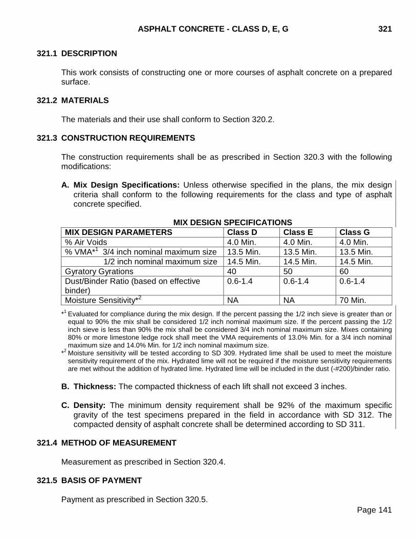
ASPHALT CONCRETE - CLASS D, E, G 321
Page 141
321.1 DESCRIPTION
This work consists of constructing one or more courses of asphalt concrete on a prepared surface.
321.2 MATERIALS
The materials and their use shall conform to Section 320.2. 321.3 CONSTRUCTION REQUIREMENTS
The construction requirements shall be as prescribed in Section 320.3 with the following modifications:
A. Mix Design Specifications: Unless otherwise specified in the plans, the mix design
criteria shall conform to the following requirements for the class and type of asphalt concrete specified.
MIX DESIGN SPECIFICATIONS
MIX DESIGN PARAMETERS Class D Class E Class G % Air Voids 4.0 Min. 4.0 Min. 4.0 Min. % VMA*1 3/4 inch nominal maximum size 13.5 Min. 13.5 Min. 13.5 Min. 1/2 inch nominal maximum size 14.5 Min. 14.5 Min. 14.5 Min. Gyratory Gyrations 40 50 60 Dust/Binder Ratio (based on effective binder)
0.6-1.4 0.6-1.4 0.6-1.4
Moisture Sensitivity*2 NA NA 70 Min.
*1 Evaluated for compliance during the mix design. If the percent passing the 1/2 inch sieve is greater than or equal to 90% the mix shall be considered 1/2 inch nominal maximum size. If the percent passing the 1/2 inch sieve is less than 90% the mix shall be considered 3/4 inch nominal maximum size. Mixes containing 80% or more limestone ledge rock shall meet the VMA requirements of 13.0% Min. for a 3/4 inch nominal maximum size and 14.0% Min. for 1/2 inch nominal maximum size.
*2 Moisture sensitivity will be tested according to SD 309. Hydrated lime shall be used to meet the moisture sensitivity requirement of the mix. Hydrated lime will not be required if the moisture sensitivity requirements are met without the addition of hydrated lime. Hydrated lime will be included in the dust (-#200)/binder ratio.
B. Thickness: The compacted thickness of each lift shall not exceed 3 inches.
C. Density: The minimum density requirement shall be 92% of the maximum specific
gravity of the test specimens prepared in the field in accordance with SD 312. The compacted density of asphalt concrete shall be determined according to SD 311.
321.4 METHOD OF MEASUREMENT
Measurement as prescribed in Section 320.4. 321.5 BASIS OF PAYMENT
Payment as prescribed in Section 320.5.

321 ASPHALT CONCRETE - CLASS D, E, G
Page 142
THIS PAGE INTENTIONALLY LEFT BLANK
ASPHALT CONCRETE - CLASS Q (New Section) 322
Page 143
322.1 DESCRIPTION
The work consists of constructing one or more courses of gyratory controlled QC/QA hot mixed asphalt concrete pavement on a prepared foundation.
322.2 MATERIALS
Mineral aggregate shall conform to the requirements of Section 322.3. All other materials and their use shall conform to Section 320.2.
322.3 CONSTRUCTION REQUIREMENTS The construction requirements shall be as prescribed in Section 320.3 with the following additional requirements: A. Laboratories:
1. Quality Control Laboratory: The Contractor shall furnish and maintain a Quality Control (QC) laboratory at the plant site. The laboratory shall be furnished with the necessary space, equipment, and supplies to properly perform all specified testing. The laboratory shall be equipped with a gyratory compactor meeting the requirements of AASHTO T 312. The laboratory equipment shall meet the requirements of the test methods contained in the Department’s Materials Manual and Materials Testing & Inspection Certification Program Manual. A copy of the equipment calibration records shall be kept in the QC laboratory.
The Contractor's QC laboratory shall be equipped with a mechanical convection oven meeting the requirements of Section 600.
The Contractor shall furnish a cut off saw equipped with a diamond tipped blade. The saw is to separate the core samples to the actual lift thickness. The cores shall be sawed by the Contractor to the correct lift line prior to testing the cores for density.
2. Quality Assurance Laboratory: The Contractor shall also provide a separate
Quality Assurance (QA) laboratory for QA testing performed by the Engineer. The QA laboratory shall meet the requirements of Section 600.
B. Quality Control:
1. Contractor Furnished Quality Control Program: QC for the asphalt concrete pavement is the responsibility of the Contractor. The Contractor shall provide and maintain a QC program. The program shall assure that all asphalt concrete materials and constructed pavement submitted for acceptance conforms to the contract requirements. The Contractor shall be responsible for all asphalt concrete materials and constructed pavement, including aggregate process control and handling.
322 ASPHALT CONCRETE - CLASS Q (New Section)
Page 144
The Contractor shall provide at least one technician certified in Asphalt Concrete Aggregate Testing and Asphalt Concrete Hot Mix Testing for conducting the QC testing and at least one technician certified in Asphalt Concrete Roadway Inspection for roadway inspection. All of the Contractors QC testing and inspection technicians shall meet the Department’s certification requirements or be under the direct supervision of a certified technician for the type of work they are actually performing. The certified testing and inspection technicians must be present at the plant and roadway whenever the plant is supplying asphalt concrete to the roadway.
At or prior to the preconstruction meeting the Contractor shall submit a QC plan to the Engineer for approval. The plan shall contain the following minimum requirements:
a. The names and phone numbers of the individual(s) responsible for the
Contractor’s QC program. b. A listing of the certified technician(s) responsible for the QC inspection, material
sampling, and testing.
c. A copy of the completed performance checklist and training and evaluation records for all temporary or seasonal personnel who will be performing QC inspection or sampling and testing.
d. An organizational chart indicating lines of authority.
e. The Contractor shall notify the Engineer if a control test strip will be used. The
Contractor may produce approximately 500 tons of material to establish a roller pattern and verify the field produced mix properties match those of the lab mix design. After test strip placement, further mixing and laydown operations will be suspended until the laboratory test results of the asphalt mixture and core densities are available. The material used in the test strip will not be included in the mix pay factor analysis. The material used in the test strip shall be tested for all the properties listed in the Department’s Materials Manual. The Engineer shall approve the location of the test strip.
If a control test strip is not constructed, the QC plan shall specify how the Contractor will establish a roller pattern to achieve the specified density and volumetric requirements.
The Engineer will provide the following to the Contractor at the preconstruction meeting:
• Names of the certified individuals in charge of Quality Assurance (QA) testing
and roadway inspection.
• An organizational chart including the names and phone numbers of those in the direct line of authority.
ASPHALT CONCRETE - CLASS Q (New Section) 322
Page 145
2. Mineral Aggregate Testing Prior to Production: The aggregate producer shall provide test results to the Contractor and Engineer for each stockpile of virgin mineral aggregate that will be incorporated into the asphalt concrete mixture a minimum of 3 weeks prior to asphalt concrete production. The aggregate producer shall use an individual certified in Asphalt Concrete Aggregate Testing. The required tests shall include gradation, crushed particles, fine aggregate angularity, flat and elongated particles, sand equivalent, and lightweight particles at the following minimum frequencies:
One test per 1500 tons for each virgin mineral aggregate ingredient produced.
A minimum of three tests for each virgin mineral aggregate stockpile.
The Contractor may vary the frequency of the crushed particles, fine aggregate angularity, flat and elongated particles, sand equivalent, and lightweight particles tests on ledge rock sources depending on the quality and uniformity of the materials.
3. Contractor Furnished Mix Designs: Asphalt concrete mix designs shall be
performed by the Contractor and verified by the Department’s Bituminous Mix Design Lab. A certified Asphalt Concrete Mix Design and Production Control technician shall perform the asphalt concrete mix design. All Contractors submitting mix designs to the Department are required to participate in the Proficiency Sample Program.
Prior to submitting samples to the Department’s Bituminous Mix Design Lab, 50% of the plans quantity or 15,000 tons, whichever is less, of the virgin mineral aggregate shall be produced. When RAP is required, the Contractor shall sample the RAP from the roadway by an approved method. The sampling method shall ensure a representative sample of material is obtained from approximately the same depth as the plans shown milling depth. The RAP sample shall be obtained from a minimum of three locations throughout the project length. The Contractor shall daylight all edges of the sampling area leaving no vertical faces or shall fill the sample area with an approved product leaving no vertical faces. The equipment used shall generate a representative sample of RAP similar to what will be produced from the cold milling operation. The Contractor shall notify the Area office a minimum of 5 calendar days prior to sampling the RAP from the roadway. A representative from the Area office shall witness all sampling of RAP to be submitted for mix design. This material shall be used to perform the mix design. A portion of this sample shall be submitted to the Department’s Bituminous Mix Design Lab. The Contractor shall notify the Area office a minimum of 5 calendar days prior to sampling and submitting the mix design aggregates. A representative from the Area office shall witness all sampling of aggregates to be submitted for mix design. A representative from the Area office shall complete the Form DOT-1 for the composite aggregate sample and RAP sample required for submittal to the
322 ASPHALT CONCRETE - CLASS Q (New Section)
Page 146
Department’s Bituminous Mix Design Lab. The Area office representative shall take possession of the aggregate and RAP samples for mix design and aggregate quality testing. Samples shall be obtained a minimum of 21 calendar days prior to hot mix production. The Area office will deliver the samples to the Department’s Bituminous Mix Design Lab in Pierre, SD. The Area office may allow the Contractor to transport and deliver the RAP and aggregate samples for mix design and aggregate quality testing only when the Area office representative has sealed the samples with a tamper evident tag, with the DOT-1 attached. Mix designs will only be performed on samples when accompanied by the following information:
a. A completed data sheet (form DOT-1), including the legal description of virgin
mineral aggregate source(s). b. Representative virgin mineral aggregate samples and RAP samples shall be
proportionate to the bin splits proposed for use during construction.
c. A summary sheet showing all test results from the gradations completed and the average gradation of each mineral aggregate stockpile produced along with the proposed bin splits to be used in the production of asphalt concrete pavement.
d. A 2 gallon sample of asphalt binder intended for use shall be obtained from the
designated supplier for the project.
e. A mix design report and moisture sensitivity test results, if required, that includes the lab data and test results required in SD 318, SD 319, and Section 322.3 B.4. The Contractor’s mix design shall meet all of the mix design specifications.
When the mix design verification is completed by the Department’s Bituminous Mix Design Lab, an approved mix design report (DOT 64) will be provided to the Area Engineer and the Contractor prior to production. The mix design report will include the single percentage of aggregate passing each required sieve size, a single percentage of asphalt binder to be added to the mixture, a single percentage of hydrated lime to be added to the mixture, a single asphalt binder application temperature, a single temperature at which the mix is to be discharged from the mixer, and a single temperature at which the mix is to be delivered on the road.
4. Gyratory Controlled QC/QA Mix Design Requirements and Specifications: Unless otherwise specified in the plans, the mix design criteria shall conform to the following requirements.
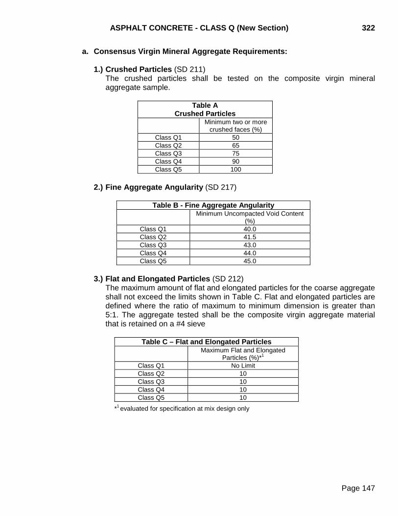
ASPHALT CONCRETE - CLASS Q (New Section) 322
Page 147
a. Consensus Virgin Mineral Aggregate Requirements:
1.) Crushed Particles (SD 211) The crushed particles shall be tested on the composite virgin mineral aggregate sample.
Table A Crushed Particles
Minimum two or more crushed faces (%)
Class Q1 50 Class Q2 65 Class Q3 75 Class Q4 90 Class Q5 100
2.) Fine Aggregate Angularity (SD 217)
Table B - Fine Aggregate Angularity Minimum Uncompacted Void Content
(%) Class Q1 40.0 Class Q2 41.5 Class Q3 43.0 Class Q4 44.0 Class Q5 45.0
3.) Flat and Elongated Particles (SD 212)
The maximum amount of flat and elongated particles for the coarse aggregate shall not exceed the limits shown in Table C. Flat and elongated particles are defined where the ratio of maximum to minimum dimension is greater than 5:1. The aggregate tested shall be the composite virgin aggregate material that is retained on a #4 sieve
Table C – Flat and Elongated Particles Maximum Flat and Elongated
Particles (%)*1
Class Q1 No Limit Class Q2 10 Class Q3 10 Class Q4 10 Class Q5 10
*1 evaluated for specification at mix design only
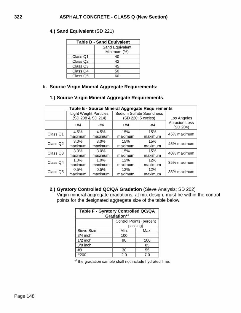
322 ASPHALT CONCRETE - CLASS Q (New Section)
Page 148
4.) Sand Equivalent (SD 221)
Table D - Sand Equivalent Sand Equivalent
Minimum (%) Class Q1 40 Class Q2 42 Class Q3 45 Class Q4 50 Class Q5 60
b. Source Virgin Mineral Aggregate Requirements:
1.) Source Virgin Mineral Aggregate Requirements
Table E - Source Mineral Aggregate Requirements Light Weight Particles
(SD 208 & SD 214) Sodium Sulfate Soundness
(SD 220; 5 cycles)
Los Angeles Abrasion Loss
(SD 204) +#4 -#4 +#4 -#4
Class Q1 4.5% maximum
4.5% maximum
15% maximum
15% maximum 45% maximum
Class Q2 3.0% maximum
3.0% maximum
15% maximum
15% maximum 45% maximum
Class Q3 3.0% maximum
3.0% maximum
15% maximum
15% maximum 40% maximum
Class Q4 1.0% maximum
1.0% maximum
12% maximum
12% maximum 35% maximum
Class Q5 0.5% maximum
0.5% maximum
12% maximum
12% maximum 35% maximum
2.) Gyratory Controlled QC/QA Gradation (Sieve Analysis; SD 202)
Virgin mineral aggregate gradations, at mix design, must be within the control points for the designated aggregate size of the table below.
Table F - Gyratory Controlled QC/QA
Gradation*1
Control Points (percent passing)
Sieve Size Min. Max. 3/4 inch 100 1/2 inch 90 100 3/8 inch 85 #8 30 55 #200 2.0 7.0
*1 the gradation sample shall not include hydrated lime.
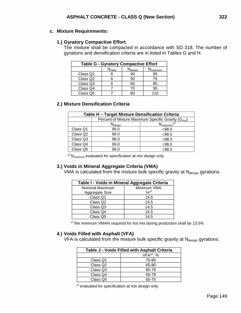
ASPHALT CONCRETE - CLASS Q (New Section) 322
Page 149
c. Mixture Requirements:
1.) Gyratory Compactive Effort The mixture shall be compacted in accordance with SD 318. The number of gyrations and densification criteria are in listed in Tables G and H.
Table G - Gyratory Compactive Effort Ninitial Ndesign Nmaximum
Class Q1 6 40 65 Class Q2 6 50 75 Class Q3 6 60 85 Class Q4 7 70 95 Class Q5 7 80 110
2.) Mixture Densification Criteria
Table H – Target Mixture Densification Criteria Percent of Mixture Maximum Specific Gravity (Gmm) Ndesign Nmaximum*1
Class Q1 96.0 ≤98.0 Class Q2 96.0 ≤98.0 Class Q3 96.0 ≤98.0 Class Q4 96.0 ≤98.0 Class Q5 96.0 ≤98.0
*1 Nmaximum evaluated for specification at mix design only
3.) Voids in Mineral Aggregate Criteria (VMA) VMA is calculated from the mixture bulk specific gravity at Ndesign gyrations.
Table I - Voids in Mineral Aggregate Criteria
Nominal Maximum Aggregate Size
Minimum VMA, %*1
Class Q1 14.5 Class Q2 14.5 Class Q3 14.5 Class Q4 14.5 Class Q5 14.5
*1 the minimum VMA% required for hot mix during production shall be 13.5% 4.) Voids Filled with Asphalt (VFA)
VFA is calculated from the mixture bulk specific gravity at Ndesign gyrations.
Table J - Voids Filled with Asphalt Criteria VFA*1, %
Class Q1 70-80 Class Q2 65-80 Class Q3 65-78 Class Q4 65-78 Class Q5 65-75
*1 evaluated for specification at mix design only
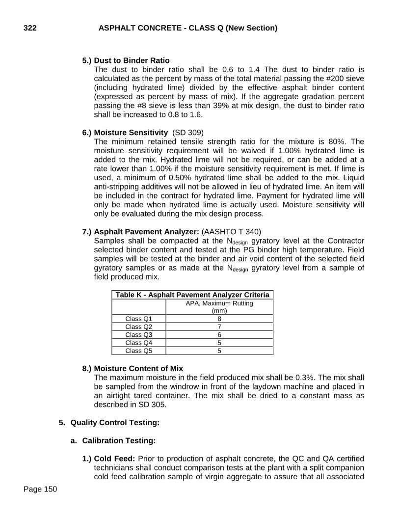
322 ASPHALT CONCRETE - CLASS Q (New Section)
Page 150
5.) Dust to Binder Ratio
The dust to binder ratio shall be 0.6 to 1.4 The dust to binder ratio is calculated as the percent by mass of the total material passing the #200 sieve (including hydrated lime) divided by the effective asphalt binder content (expressed as percent by mass of mix). If the aggregate gradation percent passing the #8 sieve is less than 39% at mix design, the dust to binder ratio shall be increased to 0.8 to 1.6.
6.) Moisture Sensitivity (SD 309) The minimum retained tensile strength ratio for the mixture is 80%. The moisture sensitivity requirement will be waived if 1.00% hydrated lime is added to the mix. Hydrated lime will not be required, or can be added at a rate lower than 1.00% if the moisture sensitivity requirement is met. If lime is used, a minimum of 0.50% hydrated lime shall be added to the mix. Liquid anti-stripping additives will not be allowed in lieu of hydrated lime. An item will be included in the contract for hydrated lime. Payment for hydrated lime will only be made when hydrated lime is actually used. Moisture sensitivity will only be evaluated during the mix design process.
7.) Asphalt Pavement Analyzer: (AASHTO T 340) Samples shall be compacted at the Ndesign gyratory level at the Contractor selected binder content and tested at the PG binder high temperature. Field samples will be tested at the binder and air void content of the selected field gyratory samples or as made at the Ndesign gyratory level from a sample of field produced mix.
Table K - Asphalt Pavement Analyzer Criteria
APA, Maximum Rutting (mm)
Class Q1 8 Class Q2 7 Class Q3 6 Class Q4 5 Class Q5 5
8.) Moisture Content of Mix
The maximum moisture in the field produced mix shall be 0.3%. The mix shall be sampled from the windrow in front of the laydown machine and placed in an airtight tared container. The mix shall be dried to a constant mass as described in SD 305.
5. Quality Control Testing:
a. Calibration Testing:
1.) Cold Feed: Prior to production of asphalt concrete, the QC and QA certified technicians shall conduct comparison tests at the plant with a split companion cold feed calibration sample of virgin aggregate to assure that all associated
ASPHALT CONCRETE - CLASS Q (New Section) 322
Page 151
equipment and procedures provide comparable results. Comparison test results shall meet the requirements of the mix design report and shall conform to the tolerances shown in the Department’s Materials Manual. The split companion calibration testing shall continue until the results meet the requirements of the mix design report and are within the listed tolerances. The split companion calibration testing shall be performed on each mix type produced prior to production of that mix type.
2.) Mixture Testing: The QC and the QA technicians shall perform correlation
testing on a reheated prebuilt split companion sample (from the mix design process) supplied by the Contractor. The correlation testing will be for the theoretical maximum specific gravity (Rice Method) and gyratory bulk specific gravities.
Two gyratory compaction samples shall be made using a compactive effort of Ndesign. The bulk specific gravity shall than be measured on specimens compacted to Ndesign gyrations. Air voids shall be calculated using the theoretical maximum specific gravity and bulk specific gravity at Ndesign gyrations. The percent of theoretical maximum specific gravity densification shall be determined at Ndesign. The results shall be within the tolerances shown in the Department’s Materials Manual.
3.) Bulk Specific Gravity Reheat Correlation: The QC and the QA technicians
shall perform a reheat correlation test for the bulk specific gravity. The reheat correlation test shall be performed on a split sample of a sublot from within the first lot of production for the mix design. An additional reheat correlation test shall be performed on a split sample of a sublot from within the first lot of production for any new mix designs.
Cool a split portion of the sample down to room temperature. After the split sample has cooled, reheat and compact according to SD 318. Calculate the difference in the bulk specific gravities of the non-reheated and reheated tests. The average difference using the QC and QA technician's test results will be the correction factor for a reheated bulk specific gravity. This test may be repeated at the discretion of the Contractor or the Engineer.
b. Asphalt Concrete Quality Control (Production) Testing: After the calibration cold feed and mixture testing is completed and the results are within the specified tolerances, the Contractor will be allowed to begin production of asphalt concrete.
The Engineer shall randomly determine all sample locations. Sampling and splitting not performed by the Engineer shall be witnessed by the Engineer. To ensure that a representative random sample is obtained, the QC sample locations shall only be given to the Contractor immediately prior to sampling. The hot mix sample shall be obtained before the cold feed gradation sample. If hydrated lime is used in the mix, the hydrated lime shall be momentarily shut off while obtaining the cold feed gradation sample. If hydrated lime is to be included
322 ASPHALT CONCRETE - CLASS Q (New Section)
Page 152
in the mix, care shall be taken to ensure that the hot mix sample is obtained with hydrated lime included in the sample. There will be a 200 ton buffer between the random sample locations. The intent of the buffer is to prevent back-to-back sampling and to more evenly distribute the sampling and testing workload. A lot shall consist of five sublots. Sublots shall not represent more than 1000 tons of asphalt concrete unless the current sublot is terminated.
The Contractor shall obtain QC samples at the specified locations for four of the five sublots. The Engineer will sample and split a minimum of one of the five sublots, and witness all QC sampling. The Contractor shall test all five sublot samples (a split of the one sublot sampled by the Engineer and four sublot samples taken by the Contractor). The material shall be sampled, split, and tested by the methods and procedures described in the Department’s Materials Manual. The aggregate and hot mix samples shall be large enough to obtain 4 splits of the minimum sample size needed for testing. If the sample is to be used for IA testing, the samples shall be large enough to obtain 6 splits of the minimum size needed for testing. Immediately after splitting, the QA technician shall take possession of half of the sample for all of the QC samples. The QA technician shall ensure the Department’s portion of the backup samples for all QC and QA tests are properly labeled, stored, and retained until the Department’s Bituminous Engineer has completed the F-test and t-test statistical evaluation. The QC technician shall retain their backup split until the QC, QA, and IA technicians have obtained their test results for the individual lot and have found the results to be within the allowable tolerances in the Department’s Materials Manual, SD 317, and the Engineer has approved the disposal of the backup samples. The Engineer will determine and mark the core locations after the mix is placed and compacted. The cores will be taken the next working day after the asphalt pavement is placed. The Contractor shall perform the coring under observation by the Engineer. The Engineer will take immediate possession of the core samples for density testing. The Contractor shall fill all core holes before the end of the next working day with hot asphalt concrete and compact the mix to a density close to that of the surrounding pavement. Core samples for density will be tested by the Engineer.
The QC technician shall complete all of the required tests on the samples selected for QA or IA testing.
c. Specification Control Limits: The control limits of materials being produced will be evaluated under two different categories, pay factor attributes and non-pay factor attributes.
ASPHALT CONCRETE - CLASS Q (New Section) 322
Page 153
1.) Pay Factor Attributes: Air voids and in place density (compaction) are the two pay factor attributes. These attributes will be statistically analyzed for contract unit price adjustment.
The percent air voids shall meet the requirement in Table L and the in place density of the asphalt concrete when expressed as a percent of the lot average maximum specific gravity (Rice Method) shall meet the requirements in Table L.
TABLE L - PAY FACTOR ATTRIBUTES
a. % Air Voids 4.0% ± 1.0%
b. In Place Density (% Compaction)
Class Q1 92.0% to 96.0% Class Q2 92.0% to 96.0% Class Q3 92.0% to 96.0% Class Q4 92.0% to 96.0% Class Q5 92.0% to 96.0%
When field test results for air voids or in place density deviate from the job mix formula values, the Contractor may adjust the gradation, asphalt binder content, or both within the allowable tolerances shown for items a, b, c, and d shown in Table N. Bin splits may be adjusted up to ± 5% from the job mix formula bin splits. Adjustments shall be made as a result of an interactive process between the Contractor and the Engineer. The Contractor's recommendations shall prevail, provided all specifications and established mix design criteria are being met. If new materials are to be incorporated into the asphalt concrete or bin split percentages are adjusted by more than 5% from the job mix formula, a new mix design will be required by the Contractor (unless otherwise approved by the Bituminous Engineer) with verification by the Department’s Bituminous Mix Design Lab. The Contractor shall be responsible to verify that all mix design criteria are being met prior to written job mix formula approval. When a new mix design and job mix formula is required, the current sublot shall be terminated and incorporated into the previous sublot for pay factor analysis. A new lot will be started when production is changed to the new job mix formula. At the end of production, the current sublot shall be terminated and incorporated into the previous sublot unless the hot mix sample and both core sample locations have been obtained and tested for the current sublot.
2.) Non-Pay Factor Attributes: There are several requirements not used in the determination of the pay factor that are very important to the performance of the asphalt concrete. The below listed attributes are tested at the frequency listed in the Department’s Materials Manual. The attributes shall be maintained within the requirements in Section 322.3 B.4 or as otherwise specified.
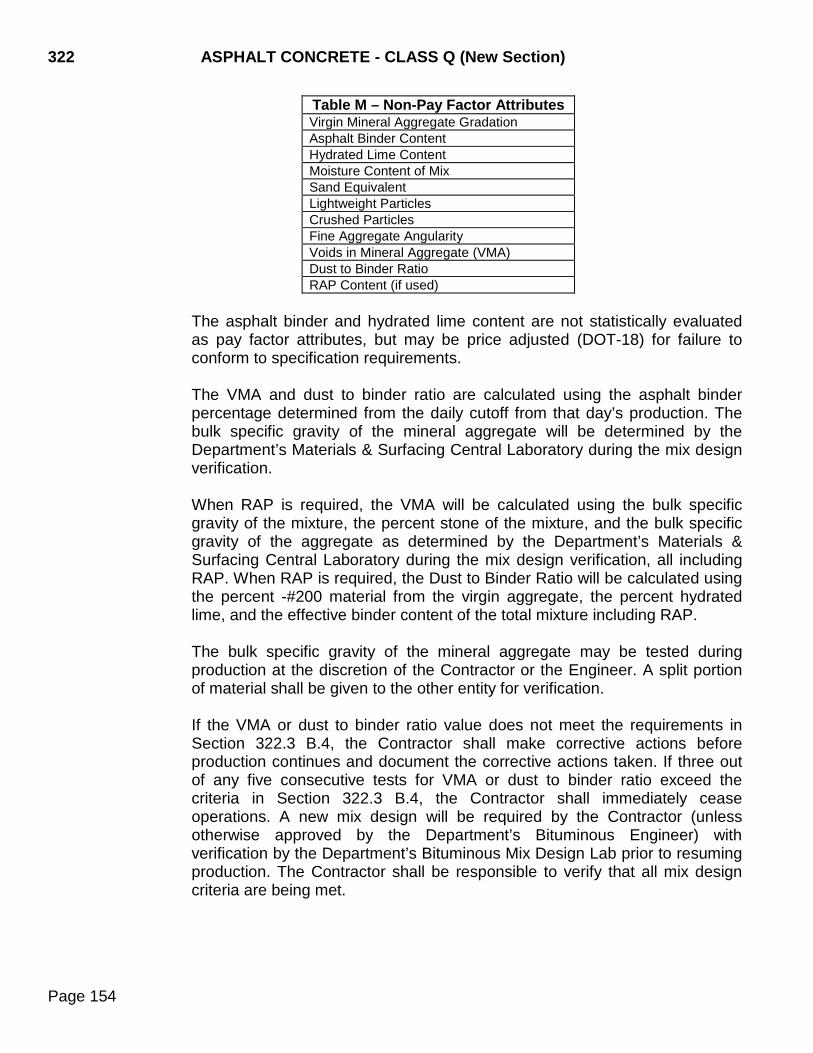
322 ASPHALT CONCRETE - CLASS Q (New Section)
Page 154
Table M – Non-Pay Factor Attributes Virgin Mineral Aggregate Gradation Asphalt Binder Content Hydrated Lime Content Moisture Content of Mix Sand Equivalent Lightweight Particles Crushed Particles Fine Aggregate Angularity Voids in Mineral Aggregate (VMA) Dust to Binder Ratio RAP Content (if used)
The asphalt binder and hydrated lime content are not statistically evaluated as pay factor attributes, but may be price adjusted (DOT-18) for failure to conform to specification requirements.
The VMA and dust to binder ratio are calculated using the asphalt binder percentage determined from the daily cutoff from that day’s production. The bulk specific gravity of the mineral aggregate will be determined by the Department’s Materials & Surfacing Central Laboratory during the mix design verification. When RAP is required, the VMA will be calculated using the bulk specific gravity of the mixture, the percent stone of the mixture, and the bulk specific gravity of the aggregate as determined by the Department’s Materials & Surfacing Central Laboratory during the mix design verification, all including RAP. When RAP is required, the Dust to Binder Ratio will be calculated using the percent -#200 material from the virgin aggregate, the percent hydrated lime, and the effective binder content of the total mixture including RAP. The bulk specific gravity of the mineral aggregate may be tested during production at the discretion of the Contractor or the Engineer. A split portion of material shall be given to the other entity for verification. If the VMA or dust to binder ratio value does not meet the requirements in Section 322.3 B.4, the Contractor shall make corrective actions before production continues and document the corrective actions taken. If three out of any five consecutive tests for VMA or dust to binder ratio exceed the criteria in Section 322.3 B.4, the Contractor shall immediately cease operations. A new mix design will be required by the Contractor (unless otherwise approved by the Department’s Bituminous Engineer) with verification by the Department’s Bituminous Mix Design Lab prior to resuming production. The Contractor shall be responsible to verify that all mix design criteria are being met.
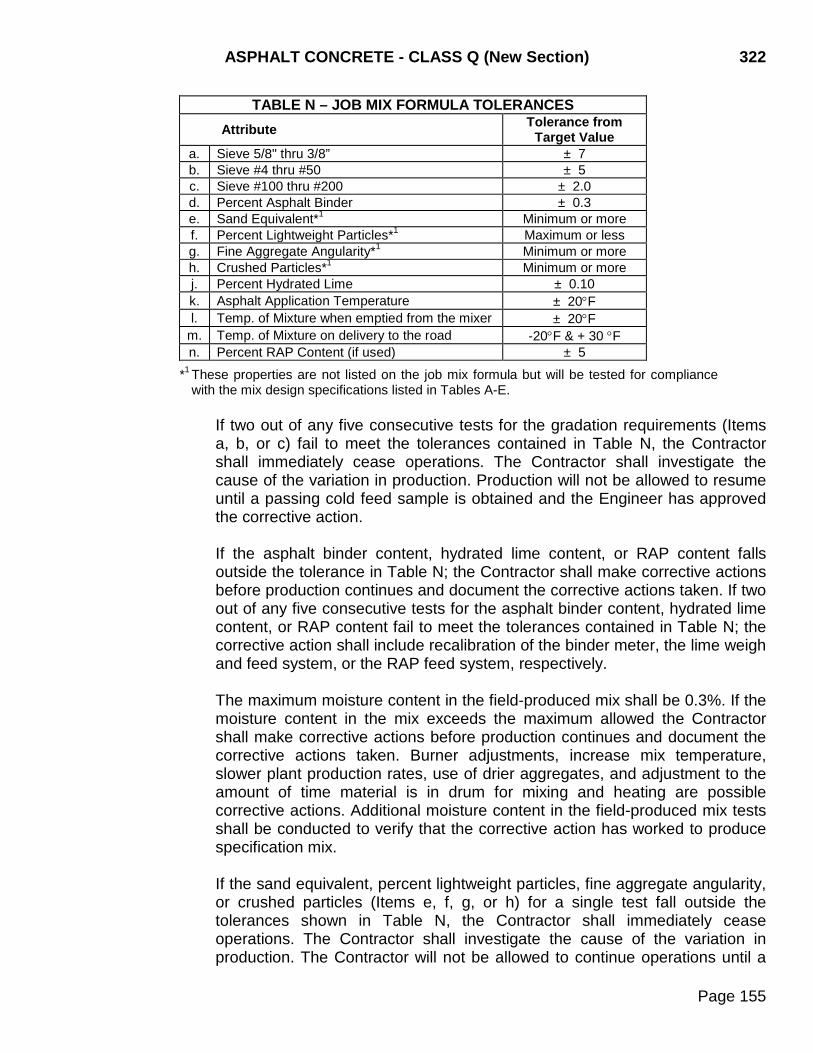
ASPHALT CONCRETE - CLASS Q (New Section) 322
Page 155
TABLE N – JOB MIX FORMULA TOLERANCES Attribute Tolerance from
Target Value a. Sieve 5/8" thru 3/8” ± 7 b. Sieve #4 thru #50 ± 5 c. Sieve #100 thru #200 ± 2.0 d. Percent Asphalt Binder ± 0.3 e. Sand Equivalent*1 Minimum or more f. Percent Lightweight Particles*1 Maximum or less g. Fine Aggregate Angularity*1 Minimum or more h. Crushed Particles*1 Minimum or more j. Percent Hydrated Lime ± 0.10 k. Asphalt Application Temperature ± 20°F l. Temp. of Mixture when emptied from the mixer ± 20°F
m. Temp. of Mixture on delivery to the road -20°F & + 30 °F n. Percent RAP Content (if used) ± 5
*1 These properties are not listed on the job mix formula but will be tested for compliance with the mix design specifications listed in Tables A-E.
If two out of any five consecutive tests for the gradation requirements (Items a, b, or c) fail to meet the tolerances contained in Table N, the Contractor shall immediately cease operations. The Contractor shall investigate the cause of the variation in production. Production will not be allowed to resume until a passing cold feed sample is obtained and the Engineer has approved the corrective action.
If the asphalt binder content, hydrated lime content, or RAP content falls outside the tolerance in Table N; the Contractor shall make corrective actions before production continues and document the corrective actions taken. If two out of any five consecutive tests for the asphalt binder content, hydrated lime content, or RAP content fail to meet the tolerances contained in Table N; the corrective action shall include recalibration of the binder meter, the lime weigh and feed system, or the RAP feed system, respectively. The maximum moisture content in the field-produced mix shall be 0.3%. If the moisture content in the mix exceeds the maximum allowed the Contractor shall make corrective actions before production continues and document the corrective actions taken. Burner adjustments, increase mix temperature, slower plant production rates, use of drier aggregates, and adjustment to the amount of time material is in drum for mixing and heating are possible corrective actions. Additional moisture content in the field-produced mix tests shall be conducted to verify that the corrective action has worked to produce specification mix. If the sand equivalent, percent lightweight particles, fine aggregate angularity, or crushed particles (Items e, f, g, or h) for a single test fall outside the tolerances shown in Table N, the Contractor shall immediately cease operations. The Contractor shall investigate the cause of the variation in production. The Contractor will not be allowed to continue operations until a
322 ASPHALT CONCRETE - CLASS Q (New Section)
Page 156
passing cold feed sample is obtained and the Engineer has approved the corrective action.
3.) Test Identification: Number the production control sublot tests consecutively in accordance with the Department’s Materials Manual starting with number “QC01” or “QC001” based on the total number of samples needed. The two density cores in a sublot shall have the same number along with an “A” or “B” designation and shall match the sublot number. The two gyratory specimens shall be numbered with the sublot number and an “A” and a “B” for the two specimens. Use “N” before the sublot number for non-pay factor material. Use “Info” before the number for information samples. Use “TS” before the sublot number for test strip samples. Use “R” after the number for remedial samples. Use “Cal” before the number for calibration samples.
4.) Control Charts: The Contractor shall provide QC charts that include the
control limits and each individual test result for the following parameters:
a) Gradation of the control sieves in the Job Mix Formula b) Asphalt Binder Content c) Hydrated Lime Content d) Maximum Specific Gravity (Rice) e) Bulk Specific Gravity (Gyratory) f) Air voids g) In place density h) VMA i) Dust to Binder Ratio QC test results shall be recorded on the control charts immediately after completion of the test. The control charts shall also include the QA and Independent Assurance test results. The control charts shall be prominently displayed and accessible to the Engineer. The control charts shall be given to the Engineer upon completion of the project.
5.) Documentation: The Contractor is responsible for documenting all observations, inspection records, mixture adjustments, test results, and corrective actions on a daily basis. The Contractor shall also record and maintain a plant record of plant starts and stops, mix temperatures leaving the plant, bin split of aggregates, and the temperature of the asphalt binder going into the mix.
Field observations and inspections shall be noted as they occur in a permanent duplicating field book or diary, provided by the Engineer. The roadway diaries shall include hours paved, equipment in use, stations paved, course depth, width, crown, spread checks, tonnage, weather, and temperature of mixture delivered to the road. Plant diaries shall include plant start and shutdown times, mix temperature of material produced, binder spot checks, aggregate bin splits being used, actual calculated asphalt binder

ASPHALT CONCRETE - CLASS Q (New Section) 322
Page 157
percentage for the day, tons of mix produced, mixture or aggregate adjustments, weather conditions, and any other pertinent information. The Engineer will collect copies of documentation records and recorded mix temperature charts daily. All records shall be made available at all times upon request by the Engineer. The test results and original work sheets, including all gyratory specimen compaction sheets, for the production control testing listed in Table M shall be given to the Engineer upon completion of the test.
C. Quality Assurance: The Engineer will randomly sample and test a minimum of one
sublot for each lot. The Engineer may test any or all of the splits of the QC sublot samples as part of the QA program. The Engineer will provide at least one individual certified in Asphalt Concrete Aggregate Testing and Asphalt Concrete Hot Mix Testing for conducting the QA testing and at least one individual certified in Asphalt Concrete Roadway Inspection for roadway inspection.
The QA technician will complete all of the required tests on the samples that are selected for QA testing. The services of contractor’s personnel to assist in obtaining the QA samples should be limited only to instances when hazardous conditions or liability issues exists that dictate their involvement and the following requirements are met: 1. The QA sample location or time is only given to the contractor immediately prior to
sampling. 2. The contractor’s personnel are used only to provide labor to assist in physically
obtaining the QA sample. 3. The Engineer is present to witness the taking of the QA sample. 4. The Engineer witnessing the sampling and the contractor labor performing the
sampling are certified in accordance with the Department’s Certification program. 5. The Engineer immediately takes possession of the QA sample.
QA test results will be made available to the Contractor within 24 hours, or the next working day.
The split sample test results (QA) of the sample taken by the Engineer will be compared to the Contractor test results (QC) for conformance with the Department’s Materials Manual. Populations of the QC sample test results will be compared to the QA sample test results utilizing the procedures shown in SD 317. If the test results are within the allowable tolerances, found to be similar, and found to represent the same population, as determined by F-test and t-test statistical evaluation procedures conducted by the Bituminous Engineer, the Contract unit price adjustments will be based on the Contractor QC test results.
Sampling and splitting not required to be performed by the Engineer will be witnessed by the Engineer.
The Engineer will test the core samples for density.
322 ASPHALT CONCRETE - CLASS Q (New Section)
Page 158
The Engineer will perform or witness the measurement of the depth of the asphalt binder in the storage tanks as described in SD 314. The Engineer will determine the temperature of the asphalt binder in the tank and will perform the daily calculation of the asphalt binder content.
The Engineer will perform the daily calculation of the hydrated lime content.
The Engineer will test the moisture content of the hot mix. The mix for the moisture test shall be sampled from the windrow in front of the laydown machine and placed in an airtight, tared container. The mix shall be dried to a constant mass as described in SD 305.
D. Independent Assurance Procedures: The Department will perform Independent
Assurance (IA) testing on project produced materials. Random samples of mineral aggregate and hot mix asphalt concrete used for QC testing will be selected by the Region Materials Engineer for IA testing.
The Region Materials Engineer will perform IA testing for the attributes listed in the Department’s Materials Manual. The tolerances from the Department’s Materials Manual will be used to independently evaluate the QC and QA testing procedures and equipment. The Region Materials Engineer shall witness the sampling and splitting of the designated IA sample (an actual sublot sample). The Region Materials Engineer may select either Engineer or Contractor sampled sublot for the IA testing.
The Region Materials Engineer will also perform IA testing for the bulk specific gravity on in place density cores. A separate IA core shall be obtained by the Contractor while obtaining the in place density core used to determine the pay factor. The IA core shall be taken at the same offset and within one foot of the core used in determining the pay factor.
E. Dispute Resolution System: Process verification procedures using F-test and t-test statistical evaluation procedures to determine if both QC and QA test results represent the same sample population may result in the need for testing backup sublot samples and substituting the new test result for pay factor calculations. If the QC and QA test results do represent the same population, as determined by F-test and t-test statistical evaluation procedures, the Contractor’s test results may be used for quality acceptance.
322.4 METHOD OF MEASUREMENT AND ACCEPTANCE
The method of measurement shall be as prescribed in Section 320.4 except the method of measurement for QA and QC field laboratories and the method of measurement and acceptance for asphalt concrete will be made according to the following: A. Asphalt Concrete: The asphalt concrete shall be statistically accepted by lots. A lot
shall consist of five sublots. Sublots shall not represent more than 1000 tons unless the current sublot is terminated. The first lot shall start at the beginning of production or following the Control Test Strip.
ASPHALT CONCRETE - CLASS Q (New Section) 322
Page 159
A lot will be terminated when a new mix design is completed and a new job mix formula is issued. If less than five sublots have been completed when a lot is terminated, the sublots will be included in the previous lot, and the pay factor computed for the revised lot. If there is no previous lot, the lot will not be terminated until five sublots are obtained.
1. Determination of Contract Unit Price Adjustment: Asphalt concrete that is not
compacted according to the Specified Density Method will not be included in the pay factor calculations but may be price adjusted (DOT-18) for failure to conform to specification requirements. The material specified to be sampled and tested on a QC/QA basis will be evaluated for payment under this subsection. All QC test results for a lot will be analyzed collectively and statistically by the Quality Level Analysis-Standard Deviation Method using the procedures herein defined. The lots will be analyzed to determine the total estimated percent of the lot that is within the specification limits.
Quality Level Analysis (specification conformance analysis) is a statistical procedure for estimating the percent of material that is within the specification limits (PWL). The PWL is determined by using the lot mean, ( X ) and the lot standard deviation(s). Two measures of quality are required to establish the contract unit price adjustment. The first measure is the Acceptable Quality Level (AQL) which is the PWL at which the lot will receive 100% pay or a composite pay factor of 1.00. The second measure of quality is the Rejectable Quality Level (RQL) at which the Engineer has determined the material may not perform as desired and may be rejected. The AQL has been selected at 90 PWL and the RQL at 60 PWL. The RQL using the pay factor equation will result in 85% pay or a pay factor of 0.85.
An individual pay factor for any attribute resulting in less than 85% pay may result in the lot being rejected.
When the Acceptable Quality Level of any individual pay factor attribute has a QL of 90 or less the composite pay factor shall not exceed 1.00.
A lot may be accepted provided the composite pay factor is at least 0.85 and there are no isolated defects identified by the Engineer. A lot containing material with less than a 0.85 composite pay factor may be rejected. All of the rejected material shall be removed from the work. The Engineer will determine if the material may remain in place at a reduced price. A lot containing material with less than a 0.85 composite pay factor may not be overlaid prior to the Engineer determining the acceptability of the lot. The Engineer may reject any quantity of material that appears to be defective based on visual inspection or test results. The visual rejection may include segregation, low temperature material, very high or low asphalt content, etc. Such rejected material
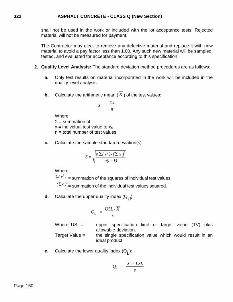
322 ASPHALT CONCRETE - CLASS Q (New Section)
Page 160
shall not be used in the work or included with the lot acceptance tests. Rejected material will not be measured for payment. The Contractor may elect to remove any defective material and replace it with new material to avoid a pay factor less than 1.00. Any such new material will be sampled, tested, and evaluated for acceptance according to this specification.
2. Quality Level Analysis: The standard deviation method procedures are as follows: a. Only test results on material incorporated in the work will be included in the
quality level analysis. b. Calculate the arithmetic mean ( X ) of the test values: Where:
Σ = summation of x = individual test value to xn n = total number of test values c. Calculate the sample standard deviation(s):
Where: Σ( x )2
= summation of the squares of individual test values.
( x )2Σ = summation of the individual test values squared. d. Calculate the upper quality index (QU):
Where: USL = upper specification limit or target value (TV) plus allowable deviation.
Target Value = the single specification value which would result in an ideal product.
e. Calculate the lower quality index (QL):
X = x
nΣ
S = n ( x )- ( x )
n(n -1)
2 2∑ ∑
UQ = USL - X
s
LQ = X - LSL
s
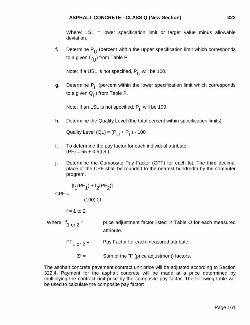
ASPHALT CONCRETE - CLASS Q (New Section) 322
Page 161
Where: LSL = lower specification limit or target value minus allowable deviation.
f. Determine PU (percent within the upper specification limit which corresponds
to a given QU) from Table P.
Note: If a USL is not specified, PU will be 100. g. Determine PL (percent within the lower specification limit which corresponds
to a given QL) from Table P. Note: If an LSL is not specified, PL will be 100.
h. Determine the Quality Level (the total percent within specification limits).
Quality Level (QL) = (PU + PL) - 100
i. To determine the pay factor for each individual attribute (PF) = 55 + 0.5(QL).
j. Determine the Composite Pay Factor (CPF) for each lot. The third decimal
place of the CPF shall be rounded to the nearest hundredth by the computer program.
[f1(PF1) + f2(PF2)] CPF =__________________ (100) Σf f = 1 to 2 Where: f1 or 2 = price adjustment factor listed in Table O for each measured
attribute. PF1 or 2 = Pay Factor for each measured attribute. Σf = Sum of the "f" (price adjustment) factors.
The asphalt concrete pavement contract unit price will be adjusted according to Section 322.4. Payment for the asphalt concrete will be made at a price determined by multiplying the contract unit price by the composite pay factor. The following table will be used to calculate the composite pay factor:
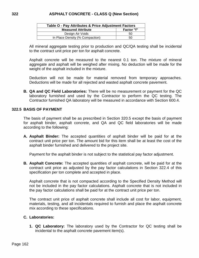
322 ASPHALT CONCRETE - CLASS Q (New Section)
Page 162
Table O - Pay Attributes & Price Adjustment Factors Measured Attribute Factor "f"
Design Air Voids 50 In Place Density (% Compaction) 50
All mineral aggregate testing prior to production and QC/QA testing shall be incidental to the contract unit price per ton for asphalt concrete. Asphalt concrete will be measured to the nearest 0.1 ton. The mixture of mineral aggregate and asphalt will be weighed after mixing. No deduction will be made for the weight of the asphalt included in the mixture. Deduction will not be made for material removed from temporary approaches. Deductions will be made for all rejected and wasted asphalt concrete pavement.
B. QA and QC Field Laboratories: There will be no measurement or payment for the QC laboratory furnished and used by the Contractor to perform the QC testing. The Contractor furnished QA laboratory will be measured in accordance with Section 600.4.
322.5 BASIS OF PAYMENT
The basis of payment shall be as prescribed in Section 320.5 except the basis of payment for asphalt binder, asphalt concrete, and QA and QC field laboratories will be made according to the following: A. Asphalt Binder: The accepted quantities of asphalt binder will be paid for at the
contract unit price per ton. The amount bid for this item shall be at least the cost of the asphalt binder furnished and delivered to the project site.
Payment for the asphalt binder is not subject to the statistical pay factor adjustment.
B. Asphalt Concrete: The accepted quantities of asphalt concrete, will be paid for at the contract unit price as adjusted by the pay factor calculations in Section 322.4 of this specification per ton complete and accepted in place.
Asphalt concrete that is not compacted according to the Specified Density Method will not be included in the pay factor calculations. Asphalt concrete that is not included in the pay factor calculations shall be paid for at the contract unit price per ton.
The contract unit price of asphalt concrete shall include all cost for labor, equipment, materials, testing, and all incidentals required to furnish and place the asphalt concrete mix according to these specifications.
C. Laboratories:
1. QC Laboratory: The laboratory used by the Contractor for QC testing shall be incidental to the asphalt concrete pavement item(s).
ASPHALT CONCRETE - CLASS Q (New Section) 322
Page 163
2. QA Laboratory: Payment for the QA laboratory will be according to Section 600.5 of the Standard Specifications.
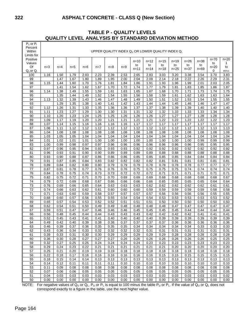
322 ASPHALT CONCRETE - CLASS Q (New Section)
Page 164
TABLE P - QUALITY LEVELS QUALITY LEVEL ANALYSIS BY STANDARD DEVIATION METHOD
Pu or Pl Percent Within
Limits for
UPPER QUALITY INDEX QU OR LOWER QUALITY INDEX QL
Positive Values
Of Qu or Ql
n=3
n=4
n=5
n=6
n=7
n=8
n=9
n=10 to
n=11
n=12 to
n=14
n=15 to
n=18
n=19 to
n=25
n=26 to
n=37
n=38 to
n=69
n=70 to
n=200
n=201 to
n=∞ 100 1.16 1.50 1.79 2.03 2.23 2.39 2.53 2.65 2.83 3.03 3.20 3.38 3.54 3.70 3.83 99 1.47 1.67 1.80 1.89 1.95 2.00 2.04 2.09 2.14 2.18 2.22 2.26 2.29 2.31 98 1.15 1.44 1.60 1.70 1.76 1.81 1.84 1.86 1.91 1.93 1.96 1.99 2.01 2.03 2.05 97 1.41 1.54 1.62 1.67 1.70 1.72 1.74 1.77 1.79 1.81 1.83 1.85 1.86 1.87 96 1.14 1.38 1.49 1.55 1.59 1.61 1.63 1.65 1.67 1.68 1.70 1.71 1.73 1.74 1.75 95 1.35 1.44 1.49 1.52 1.54 1.55 1.56 1.58 1.59 1.61 1.62 1.63 1.63 1.64 94 1.13 1.32 1.39 1.43 1.46 1.47 1.48 1.49 1.50 1.51 1.52 1.53 1.54 1.55 1.55 93 1.29 1.35 1.38 1.40 1.41 1.42 1.43 1.44 1.44 1.45 1.46 1.46 1.47 1.47 92 1.12 1.26 1.31 1.33 1.35 1.36 1.36 1.37 1.37 1.38 1.39 1.39 1.40 1.40 1.40 91 1.11 1.23 1.27 1.29 1.30 1.30 1.31 1.31 1.32 1.32 1.33 1.33 1.33 1.34 1.34 90 1.10 1.20 1.23 1.24 1.25 1.25 1.26 1.26 1.26 1.27 1.27 1.27 1.28 1.28 1.28 89 1.09 1.17 1.19 1.20 1.20 1.21 1.21 1.21 1.21 1.22 1.22 1.22 1.22 1.22 1.23 88 1.07 1.14 1.15 1.16 1.16 1.16 1.16 1.17 1.17 1.17 1.17 1.17 1.17 1.17 1.17 87 1.06 1.11 1.12 1.12 1.12 1.12 1.12 1.12 1.12 1.12 1.12 1.12 1.12 1.13 1.13 86 1.04 1.08 1.08 1.08 1.08 1.08 1.08 1.08 1.08 1.08 1.08 1.08 1.08 1.08 1.08 85 1.03 1.05 1.05 1.04 1.04 1.04 1.04 1.04 1.04 1.04 1.04 1.04 1.04 1.04 1.04 84 1.01 1.02 1.01 1.01 1.00 1.00 1.00 1.00 1.00 1.00 1.00 1.00 0.99 0.99 0.99 83 1.00 0.99 0.98 0.97 0.97 0.96 0.96 0.96 0.96 0.96 0.96 0.96 0.95 0.95 0.95 82 0.97 0.96 0.95 0.94 0.93 0.93 0.93 0.92 0.92 0.92 0.92 0.92 0.92 0.92 0.92 81 0.96 0.93 0.91 0.90 0.90 0.89 0.89 0.89 0.89 0.88 0.88 0.88 0.88 0.88 0.88 80 0.93 0.90 0.88 0.87 0.86 0.86 0.86 0.85 0.85 0.85 0.85 0.84 0.84 0.84 0.84 79 0.91 0.87 0.85 0.84 0.83 0.82 0.82 0.82 0.82 0.81 0.81 0.81 0.81 0.81 0.81 78 0.89 0.84 0.82 0.80 0.80 0.79 0.79 0.79 0.78 0.78 0.78 0.78 0.77 0.77 0.77 77 0.87 0.81 0.78 0.77 0.76 0.76 0.76 0.75 0.75 0.75 0.75 0.74 0.74 0.74 0.74 76 0.84 0.78 0.75 0.74 0.73 0.73 0.72 0.72 0.72 0.71 0.71 0.71 0.71 0.71 0.71 75 0.82 0.75 0.72 0.71 0.70 0.70 0.69 0.69 0.69 0.68 0.68 0.68 0.68 0.68 0.67 74 0.79 0.72 0.69 0.68 0.67 0.66 0.66 0.66 0.66 0.65 0.65 0.65 0.65 0.64 0.64 73 0.76 0.69 0.66 0.65 0.64 0.63 0.63 0.63 0.62 0.62 0.62 0.62 0.62 0.61 0.61 72 0.74 0.66 0.63 0.62 0.61 0.60 0.60 0.60 0.59 0.59 0.59 0.59 0.59 0.58 0.58 71 0.71 0.63 0.60 0.59 0.58 0.57 0.57 0.57 0.57 0.56 0.56 0.56 0.56 0.55 0.55 70 0.68 0.60 0.57 0.56 0.55 0.55 0.54 0.54 0.54 0.53 0.53 0.53 0.53 0.53 0.52 69 0.65 0.57 0.54 0.53 0.52 0.52 0.51 0.51 0.51 0.50 0.50 0.50 0.50 0.50 0.50 68 0.62 0.54 0.51 0.50 0.49 0.49 0.48 0.48 0.48 0.48 0.47 0.47 0.47 0.47 0.47 67 0.59 0.51 0.47 0.47 0.46 0.46 0.46 0.45 0.45 0.45 0.45 0.44 0.44 0.44 0.44 66 0.56 0.48 0.45 0.44 0.44 0.43 0.43 0.43 0.42 0.42 0.42 0.42 0.41 0.41 0.41 65 0.52 0.45 0.43 0.41 0.41 0.40 0.40 0.40 0.40 0.39 0.39 0.39 0.39 0.39 0.39 64 0.49 0.42 0.40 0.39 0.38 0.38 0.37 0.37 0.37 0.37 0.36 0.36 0.36 0.36 0.36 63 0.46 0.39 0.37 0.36 0.35 0.35 0.35 0.34 0.34 0.34 0.34 0.34 0.33 0.33 0.33 62 0.43 0.36 0.34 0.33 0.32 0.32 0.32 0.32 0.31 0.31 0.31 0.31 0.31 0.31 0.31 61 0.39 0.33 0.31 0.30 0.30 0.29 0.29 0.29 0.29 0.29 0.28 0.28 0.28 0.28 0.28 60 0.36 0.30 0.28 0.27 0.27 0.27 0.26 0.26 0.26 0.26 0.26 0.26 0.26 0.25 0.25 59 0.32 0.27 0.25 0.25 0.24 0.24 0.24 0.24 0.23 0.23 0.23 0.23 0.23 0.23 0.23 58 0.29 0.24 0.23 0.22 0.21 0.21 0.21 0.21 0.21 0.21 0.20 0.20 0.20 0.20 0.20 57 0.25 0.21 0.20 0.19 0.19 0.19 0.18 0.18 0.18 0.18 0.18 0.18 0.18 0.18 0.18 56 0.22 0.18 0.17 0.16 0.16 0.16 0.16 0.16 0.16 0.15 0.15 0.15 0.15 0.15 0.15 55 0.18 0.15 0.14 0.14 0.13 0.13 0.13 0.13 0.13 0.13 0.13 0.13 0.13 0.13 0.13 54 0.14 0.12 0.11 0.11 0.11 0.11 0.10 0.10 0.10 0.10 0.10 0.10 0.10 0.10 0.10 53 0.11 0.09 0.08 0.08 0.08 0.08 0.08 0.08 0.08 0.08 0.08 0.08 0.08 0.08 0.08 52 0.07 0.06 0.06 0.05 0.05 0.05 0.05 0.05 0.05 0.05 0.05 0.05 0.05 0.05 0.05 51 0.04 0.03 0.03 0.03 0.03 0.03 0.03 0.03 0.03 0.03 0.03 0.03 0.03 0.03 0.02 50 0.00 0.00 0.00 0.00 0.00 0.00 0.00 0.00 0.00 0.00 0.00 0.00 0.00 0.00 0.00
NOTE: For negative values of QU or QL, PU or PL is equal to 100 minus the table PU or PL. If the value of QU or QL does not correspond exactly to a figure in the table, use the next higher value.
ASPHALT CONCRETE COMPOSITE 324
Page 165
324.1 DESCRIPTION This work consists of constructing one or more courses of asphalt concrete and treating a prepared surface with asphalt material and sand as required.
324.2 MATERIALS
The materials for treating a prepared surface shall conform to Section 330.2. The materials for asphalt concrete composite and their use shall conform to Section 320.2 except as modified by the following: The mineral aggregate for asphalt concrete composite shall conform to Section 321 - Class E, Type 1, with the following modifications:
The asphalt binder used in the mixture shall be PG 64-22, PG 64-28, PG 58-34, or PG 64-34 unless otherwise specified in the plans. The Contractor shall provide a job mix formula to the Department’s Bituminous Engineer with supporting mix design data prior to production. The asphalt binder content may be adjusted by the Engineer. The Engineer may accept the mixture on the basis of the Certificates of Compliance and visual inspection or may test the mixture for specification compliance.
324.3 CONSTRUCTION REQUIREMENTS
The construction requirements shall be as prescribed in Section 320.3 and 330.3 with the following modifications:
A. Density: Compaction of the asphalt concrete composite shall be by methods and to a
density satisfactory to the Engineer. B. Thickness: The compacted thickness of each lift shall not exceed 3 inches.
C. Asphalt: Asphalt for tack SS-1h or CSS-1h shall be applied prior to each lift of asphalt
concrete. Asphalt for tack shall be applied at a rate of 0.10 gallons per square yard on existing pavement or milled asphalt concrete surface and at a rate of 0.05 gallons per square yard on new asphalt concrete pavement. Asphalt for flush seal SS-1h or CSS-1h and sand for flush seal shall be applied to the final lift of asphalt concrete in accordance with Section 330. Asphalt for flush seal shall be applied at a rate of 0.05 gallons per square yard and sand for flush seal shall be applied at a rate of 8 pounds per square yard.
D. The requirement for a paver feeder from Section 320.3 G is waived.
324 ASPHALT CONCRETE COMPOSITE
Page 166
324.4 METHOD OF MEASUREMENT Measurement will be to the nearest 0.1 ton.
324.5 BASIS OF PAYMENT
Asphalt concrete composite shall be paid for at the contract unit price per ton for asphalt concrete composite furnished complete in place. Asphalt concrete composite shall include mineral aggregate, asphalt binder, asphalt for tack SS-1h or CSS-1h, asphalt for flush seal SS-1h or CSS-1h, sand for flush seal, equipment, labor, and incidentals necessary. When required, the following shall also be included in the contract unit price per ton for asphalt concrete composite: asphalt for prime MC-70, blotting sand for prime, hydrated lime, equipment, labor, and incidentals necessary.
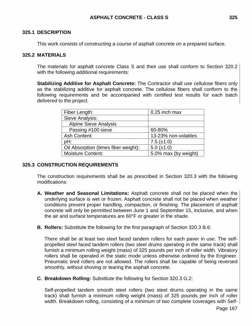
ASPHALT CONCRETE - CLASS S 325
Page 167
325.1 DESCRIPTION This work consists of constructing a course of asphalt concrete on a prepared surface.
325.2 MATERIALS
The materials for asphalt concrete Class S and their use shall conform to Section 320.2 with the following additional requirements:
Stabilizing Additive for Asphalt Concrete: The Contractor shall use cellulose fibers only as the stabilizing additive for asphalt concrete. The cellulose fibers shall conform to the following requirements and be accompanied with certified test results for each batch delivered to the project.
Fiber Length: 0.25 inch max Sieve Analysis:
Alpine Sieve Analysis Passing #100 sieve 60-80%
Ash Content: 13-23% non-volatiles pH: 7.5 (±1.0) Oil Absorption (times fiber weight): 5.0 (±1.0) Moisture Content: 5.0% max (by weight)
325.3 CONSTRUCTION REQUIREMENTS
The construction requirements shall be as prescribed in Section 320.3 with the following modifications: A. Weather and Seasonal Limitations: Asphalt concrete shall not be placed when the
underlying surface is wet or frozen. Asphalt concrete shall not be placed when weather conditions prevent proper handling, compaction, or finishing. The placement of asphalt concrete will only be permitted between June 1 and September 15, inclusive, and when the air and surface temperatures are 60°F or greater in the shade.
B. Rollers: Substitute the following for the first paragraph of Section 320.3 B.6:
There shall be at least two steel faced tandem rollers for each paver in use. The self-propelled steel faced tandem rollers (two steel drums operating in the same track) shall furnish a minimum rolling weight (mass) of 325 pounds per inch of roller width. Vibratory rollers shall be operated in the static mode unless otherwise ordered by the Engineer. Pneumatic tired rollers are not allowed. The rollers shall be capable of being reversed smoothly, without shoving or tearing the asphalt concrete.
C. Breakdown Rolling: Substitute the following for Section 320.3 G.2: Self-propelled tandem smooth steel rollers (two steel drums operating in the same track) shall furnish a minimum rolling weight (mass) of 325 pounds per inch of roller width. Breakdown rolling, consisting of a minimum of two complete coverages with Self-
325 ASPHALT CONCRETE - CLASS S
Page 168
propelled tandem smooth steel rollers, shall proceed on the mat as soon as laydown is completed. Operations shall be scheduled so breakdown rolling is completed on a segment within 300 feet of the laydown. Final or finish rolling shall consist of a minimum of one complete coverage with a Self-propelled tandem smooth steel roller. Completion of rolling shall not lag behind the laydown by a distance of more than 600 feet. During periods of cool weather this maximum distance between laydown and final rolling shall be reduced as ordered by the Engineer. Compaction to a specified density will not be required. However, additional roller coverage may be required in order to obtain a smooth surface finish.
D. Stabilizing Additive for Asphalt Concrete: Add the following to Section 320.3 C:
5. The asphalt concrete mixture shall meet the 0.3% maximum drain down percent in uncompacted bituminous paving mixtures requirement when tested in accordance with SD 306. If the asphalt concrete mixture drain down percent exceeds the maximum allowed, the Contractor will be required to add a stabilizing additive to the mixture to prevent drain down of the asphalt binder and mineral aggregate according to the following:
Stabilizing additives shall be introduced into the mixture using a stabilizer supply system recommended by the manufacturer of the additive. The supply system shall be a separate system that proportions the required amount of stabilizer in a uniform distribution. The system shall include low level and no-flow indicators and a printout of status of feed rate in lbs/min. The stabilizer supply line shall include a section of transparent pipe for observing consistency of flow or feed. Stabilizing additive shall be added at a dosage rate between 0.2% and 0.4% by weight of the total mix as determined by the mix designer. If the stabilizing additive content falls outside a tolerance of ±10% by total weight of desired stabilizing additive from the job mix formula target, the Contractor shall stop production until corrective measures are taken.
325.4 METHOD OF MEASUREMENT
Measurement as prescribed in Section 320.4 with the following addition: G. Stabilizing Additive for Asphalt Concrete: Stabilizing additive for asphalt concrete,
when provided, will be measured to the nearest 0.1 ton.
325.5 BASIS OF PAYMENT Payment as prescribed in Section 320.5 with the following addition:
G. Stabilizing Additive for Asphalt Concrete: Stabilizing additive for asphalt concrete
will be paid for at the contract unit price per ton including all cost for labor, equipment, and materials associated with the addition of the stabilizing additive for asphalt concrete complete in place.
ASPHALT CONCRETE - CLASS HR 326
Page 169
326.1 DESCRIPTION This work consists of constructing one or more courses of asphalt concrete with RAP on a prepared surface.
326.2 MATERIALS The materials for asphalt concrete Class HR and their use shall conform to Section 320.2 except as modified by the following: Asphalt concrete aggregates shall consist of RAP and virgin aggregate. The proportions of materials in the mixture will be determined by the job mix formula. The virgin mineral aggregate for asphalt concrete Class HR shall conform to Section 321 - Class E, Type 1. The virgin aggregates shall meet the specifications of the class and type specified. The combined virgin aggregate and RAP will not be further tested for gradation or quality control purposes.
326.3 CONSTRUCTION REQUIREMENTS The construction requirements shall be as prescribed in Section 320.3 with the following modifications: A. The compacted thickness of each lift shall not exceed 3 inches. B. The minimum density requirement shall be 92% of the maximum specific gravity of the
test specimens prepared in the field in accordance with SD 312. The compacted density of asphalt concrete shall be determined according to SD 311.
C. The RAP, virgin aggregate materials, and asphalt cement shall be mixed by a
conventional hot mix batch plant or a drum mix type hot plant. 326.4 METHOD OF MEASUREMENT
Measurement as provided in Section 320.4.
326.5 BASIS OF PAYMENT Payment as provided in Section 320.5.

326 ASPHALT CONCRETE - CLASS HR
Page 170
THIS PAGE INTENTIONALLY LEFT BLANK
PRIME, TACK, FOG SEAL, AND FLUSH SEAL 330
Page 171
330.1 DESCRIPTION
This work consists of preparing and treating a prepared surface with asphalt material and sand as required.
330.2 MATERIALS
Materials shall conform to the following Sections:
A. Asphalt: Section 890. B. Blotting Sand for Prime: Section 879. C. Sand for Flush Seal: Section 879. D. Sand for Fog Seal: Section 879.
330.3 CONSTRUCTION REQUIREMENTS
A. Weather and Seasonal Requirements:
Application shall be made only during daylight hours, when the wind does not adversely affect the spraying operation and when the following conditions are met: 1. Asphalt for Prime: The application of asphalt for prime will be permitted only:
a. When the ambient air and surface temperatures on the project are both at least
60°F in the shade.
b. When conditions are dry.
When plans call for prime on interim surfacing, the prime application shall closely follow the base finishing operation and at no time shall the prime operation be more than 3 miles from the base finishing operation. The cure time for the processed base, prime, and blotting sand application will be determined by the Engineer. Surfaces primed with cutback asphalt shall be allowed to cure for a minimum of 72 hours prior to being overlaid with asphalt concrete.
2. Asphalt for Tack: The application of asphalt for tack will be permitted only:
a. When the ambient air and surface temperature on the project are both at least 35°F in the shade.
b. When conditions are dry, except emulsified asphalt may be applied when the
surface is slightly damp.
330 PRIME, TACK, FOG SEAL, AND FLUSH SEAL
Page 172
3. Asphalt for Fog Seal: The application of asphalt for fog seal will be permitted only:
a. When the ambient air and surface temperature on the project are both at least 60°F in the shade.
b. When conditions are dry.
4. Asphalt for Flush Seal: The application of asphalt for flush seal will be permitted only:
a. Between May 1 and November 1, inclusive. b. When ambient air and surface temperatures on the project are both at least 50°F
in the shade. c. When the surface is dry or slightly damp.
B. Dilution of Tack, Fog Seal, and Flush Seal: Emulsified asphalt for tack, fog seal, and
flush seal with a specified application rate of 0.05 gallons per square yard or less may be diluted. The rate of dilution shall be at a ratio of at least 1 part emulsion to no more than 1 part added water (1:1 ratio minimum) by volume, unless otherwise approved by the Engineer. The emulsion shall be uniformly mixed by adding potable water and if necessary, agitating the mixture. The amount of emulsion and any added water shall be included on the ticket delivered to the project. If the emulsion is diluted, the emulsified asphalt supplier shall perform the dilution. Dilution of asphalt emulsion in the field will not be allowed unless approved by the Engineer. Field dilution of the emulsified asphalt will only be allowed when the rate of dilution is accurately controlled. The final rate of dilution shall not be less than the minimum ratio of at least 1 part emulsion to no more than 1 part added water (1:1 ratio minimum). Diluted emulsified asphalt for tack, fog seal, and flush seal shall be applied at an adjusted rate proportional to the dilution ratio resulting in application of the specified rate of emulsion. Emulsified asphalt for tack, fog seal, or flush seal with a specified rate exceeding 0.05 gallons per square yard may not be diluted.
C. Equipment:
The following minimum equipment shall be furnished by the Contractor.
1. Brooms:
a. Pickup Broom: In curb and gutter sections or in rural sections where a finished and maintained lawn extends to the edge of the shoulder, the Contractor must use a pickup broom with an integral self-contained storage. The pickup broom must be a minimum of 6 feet wide and must have working gutter brooms.
b. Rotary Power Broom: A rotary power broom may be used in all other areas.

PRIME, TACK, FOG SEAL, AND FLUSH SEAL 330
Page 173
2. Heating Equipment: Equipment for heating the asphalt material in or at the tank car, transport truck, or distributor shall be designed and constructed to heat the material without burning, scorching, or overheating, and with positive control of the heat. The introduction of steam directly into the material will not be permitted.
3. Distributors: Distributors used to apply the asphalt material shall be self-propelled,
equipped with pressure type mechanical circulating pumps and valves, a heating system and insulated tank, which will provide the uniform required temperature throughout the entire contents of the distributor tank. The distributor shall have a capacity of at least 800 gallons. Detachable distributor units separate from the tank will not be allowed.
The distributor shall uniformly apply the heated asphalt material to the road surface in accurately measured quantities, and maintain the specified rate of application during the distribution of the entire tank-load, regardless of change in gradient, superelevation, direction, or content level in the tank. Calibration runs for verification shall be made at the start of the work.
The spray nozzles shall be designed, sized, and arranged to ensure uniform distribution of heated asphalt material at the designated rate, in an overlapping fan shaped spray without surge, streaks, ridges, or bare spots. A strainer shall be provided in the discharge line to prevent nozzles from clogging. The output of each and every nozzle on the bar shall be the same and a test shall be made, in advance of use to determine compliance with this requirement. Different sizes, heights, pressures, and settings of nozzles for different designated rates shall be provided.
The distributor shall be equipped with a tachometer, clearly visible to the operator, which accurately shows the speed in feet per minute. Pressure metering distributors shall be furnished with an accurate pressure gauge showing the distribution pressure. Volume metering distributors shall be furnished with a pump tachometer or meter showing the volume furnished. The distributor shall include an accurate, mercury actuated thermometer showing the temperature of the material in the tank and a contents gauge showing the number of gallons in the tank at any content level. The distributor shall be equipped with adjustable spray bars arranged so the application width will be available in 2 foot intervals. The distributor spray bars shall be capable of operating at a constant controlled height and shall be of the full circulating type. Each nozzle of the distributor bar shall be equipped with a cutoff valve, which immediately stops the flow without dripping. Compliance with these requirements must be proven before the distributor can be used.
D. Surface Preparation: The surface shall be thoroughly swept and cleaned of all foreign material. Appurtenances immediately adjacent to the surface to be treated shall be protected from the splatter of asphalt. Manhole covers, water shut valves, and other
330 PRIME, TACK, FOG SEAL, AND FLUSH SEAL
Page 174
utility access points shall be covered to ensure liquid asphalt is not applied to them, as directed by the Engineer. Surfaces to receive a prime coat shall be satisfactorily compacted and cured.
E. Application of Asphalt: During application the temperature of the asphalt shall be
maintained within the temperature range furnished by the asphalt supplier. Asphalt shall be applied by a pressure distributor in a uniform and continuous manner. Coverage shall be made to the satisfaction of the Engineer.
Unauthorized increases in rate of application will not be eligible for payment. The angle of the spray nozzles and the height of the spray bar shall be set to obtain uniform distribution. The distributor shall travel at the established speed when the spray bar is opened. Areas inaccessible to the distributor shall be covered by hand spray methods. When the distributor is not in operation, it shall be parked off the roadbed or drip pans shall be placed under the spray bar. Tack application ahead of mat laydown shall be limited by job conditions and shall not exceed the amount estimated for the current day's operation unless ordered or allowed by the Engineer. Tacked areas, which become unsatisfactory as a result of traffic, weather, or other conditions, shall be retacked. Required retacking which is not the fault of the Contractor will be paid for at the contract unit price for tack asphalt.
F. Application of Sand: Blotting of prime shall be accomplished by broom sweeping or spreading sand on the primed surface with a mechanical spreader. Hand spreading will be permitted on odd shaped or inaccessible areas. Application of sand will not be permitted until the prime has set for at least 24 hours, unless otherwise directed by the Engineer.
The fresh application of asphalt for flush seal shall be covered with a uniform spread of sand immediately behind the distributor. The sand shall be placed by a self-powered aggregate spreader with positive controls or other equipment acceptable to the Engineer. The sand shall be placed uniformly on the asphalt application. Rolling will not be required. The finished surface shall be smooth riding without transverse or longitudinal ridges and shall present a uniform satisfactory appearance. Bleeding areas shall be resanded. Rough and nonuniform areas shall be corrected.
When applying fog seal coats, a light application of sand may be ordered by the Engineer to prevent material pick up. If ordered, the sand shall be placed by a self-powered aggregate spreader with positive controls or other equipment acceptable to the Engineer. The sand shall be placed uniformly on the asphalt application. Rolling will not be required. The finished surface shall be smooth riding without transverse or longitudinal ridges and shall present a uniform satisfactory appearance. Bleeding areas shall be resanded. Rough and nonuniform areas shall be corrected. The loose sand material remaining on the surface shall be lightly broomed off after a waiting period of twenty-four hours from the time of application or as otherwise directed
PRIME, TACK, FOG SEAL, AND FLUSH SEAL 330
Page 175
by the Engineer. Excess material in curb and gutter sections shall be broomed towards the gutter and shall be picked up and disposed of by the Contractor.
Unauthorized increases in rate of application will not be eligible for payment.
G. Temporary Traffic Control: The Contractor shall provide flaggers, signs, and barriers
to warn, direct, and prevent traffic from traveling on the freshly applied asphalt until it has penetrated, and does not track or pickup on the tires of traveling vehicles or the surface has been blotted with sand. Temporary traffic control shall conform to Section 634.
330.4 METHOD OF MEASUREMENT
A. Asphalt: Asphalt will be measured to the nearest 0.1 ton.
B. Blotting Sand for Prime: Blotting sand for prime will be measured to the nearest 0.1 ton.
C. Sand for Flush Seal: Sand for flush seal will be measured to the nearest 0.1 ton. D. Sand for Fog Seal: Sand for fog seal will be measured to the nearest 0.1 ton.
330.5 BASIS OF PAYMENT
A. Asphalt: Asphalt will be paid for at the contract unit price per ton complete in place. Separate payment will not be made for water for dilution of emulsified asphalt.
B. Blotting Sand for Prime: Blotting sand for prime will be paid for at the contract unit
price per ton complete in place. Payment will be full compensation for furnishing, installing, and all incidentals required to complete the work.
C. Sand for Flush Seal: Sand for flush seal will be paid for at the contract unit price per
ton complete in place. Payment will be full compensation for furnishing, installing, and all incidentals required to complete the work.
D. Sand for Fog Seal: Sand for fog seal will be paid for at the contract unit price per ton
complete in place. Payment will be full compensation for furnishing, installing, and all incidentals required to complete the work.

330 PRIME, TACK, FOG SEAL, AND FLUSH SEAL
Page 176
THIS PAGE INTENTIONALLY LEFT BLANK
COLD MILLING ASPHALT CONCRETE 332
Page 177
332.1 DESCRIPTION
This work consists of cold milling a portion of the existing asphalt concrete surface course and hauling and stockpiling the removed material.
332.2 MATERIALS
Cold milled asphalt concrete shall conform to the requirements of Section 884.
332.3 CONSTRUCTION REQUIREMENTS
A. General: The material shall be removed by cold milling with the specified equipment, without the use of heat.
The Contractor shall not dispose of cold milled asphalt concrete material or use the cold milled material for any purpose other than purposes designated in the plans without approval by the Engineer.
B. Equipment: The equipment for cold milling shall consist of a rotating drum equipped
with teeth capable of removing material to a depth of up to 3 inches in one pass, producing a uniform surface finish.
The cold milling machine shall establish a longitudinal profile grade within ±1/8 inch referenced from a traveling stringline or erected fixed string line and shall be controlled by an automatic system for controlling grade. The cold milling machine shall be equipped so that the depth and transverse slope of the drum is manually or automatically controlled using the traveling or fixed stringline on either or both sides of the milling machine. The fixed stringline shall remain taut after being tightened. The traveling stringline shall have a minimum effective length of 28 feet. The traveling stringline shall be attached and positioned on the milling machine to reference the longitudinal profile. The traveling stringline shall utilize either mechanical skis or non-contacting grade averaging sensors. If mechanical skis are provided, the sensor of the control system shall rest midway between the traveling stringline. Following milling of the first pass, adjacent passes shall be milled referencing the traveling stringline riding on the previously milled pass or a fixed stringline. A shoe attachment may be used to match an adjacent reference point when directed by the Engineer.
The drum shall be capable of tilting to allow feathering of edges to zero cut.
C. Construction Methods: The existing surface of the pavement shall be removed by
milling to the depth, width, cross section, and grade specified. The resulting milled surface shall be free of detrimental ridges or grooves. The final pavement surface shall have a transverse pattern of 3/4 inch center to center of each strike area. The difference between the ridge and valley of the mat surface shall not exceed 1/4 inch.
332 COLD MILLING ASPHALT CONCRETE
Page 178
The milled section shall be finished to the cross slope shown on the typical section ±0.2%. The quarter crown within any 12 foot transverse length (or the actual lane width paved with a single paver pass) shall not exceed 0.04 foot when measured with a straightedge, stringline, or other suitable equipment. The Engineer may order changes to the typical section if field conditions warrant. All vertical cuts from cold milling operations left and right of the centerline shall be daylighted to the outside edge of the road to allow surface water to be drained off of the roadway. Daylighting shall be accomplished by methods satisfactory to the Engineer. When Traffic will be exposed to the milled surface, all cold milling asphalt concrete shall be accomplished on one-half of the roadway at a time. The contractor shall schedule the cold milling asphalt concrete operations so that there are no drop offs, uneven lanes, or windrows of milled material remaining on the roadway overnight. At the end of the day the Contractor shall place cold milled asphalt concrete material to provide temporary ramps as a transition onto or off of the milled surface and the project limits, bridge approaches, and intersecting roads. The resultant transition shall be of sufficient length to provide a slope no steeper than 20:1. 1. Cold Milling Asphalt Concrete and Placing Cold Milled Material: The Contractor
shall place the cold milled asphalt concrete material directly on the shoulder of the roadway to the dimensions of the typical sections or as directed by the Engineer. The Contractor may need to adjust the depth of milling due to rutting or other roadway irregularities to create the proper grade line, cross section, and cross slope and to obtain the material required for the shoulders. Some areas of the shoulder may require the movement of cold milled asphalt concrete material either ahead or back to achieve the required cross section. No separate payment will be made for the movement of this material. Material placed on the shoulders shall be compacted according to Section 260.3 D except that a pneumatic tired roller with an effective roller weight of at least 250 pounds per inch of roller width will be required. At the time of compaction, the cold milled asphalt concrete material placed on the shoulder shall contain approximately 4% moisture uniformly blended throughout the depth of the material. The percent moisture may be adjusted by the Engineer. Prior to allowing traffic on the milled surface, the surface shall be thoroughly broomed free of remaining loose material. In rural sections where a finished and maintained lawn extends to the edge of the shoulder, the Contractor shall use a pickup broom with an integral self-contained storage. The pickup broom must be a minimum of 6 feet wide. A rotary power broom may be used in all other areas.
2. Cold Milling Asphalt Concrete: Loose material resulting from the milling shall be immediately picked up, hauled to the stockpile site(s), and stockpiled. Prior to allowing traffic on the milled surface, the surface shall be thoroughly broomed free of remaining loose material. In curb and gutter sections or in rural sections where a
COLD MILLING ASPHALT CONCRETE 332
Page 179
finished and maintained lawn extends to the edge of the shoulder, the Contractor shall use a pickup broom with an integral self-contained storage. The pickup broom must be a minimum of 6 feet wide. While sweeping in curb and gutter sections, the pickup broom must have working gutter brooms. A rotary power broom may be used in all other areas. Cold milled asphalt concrete material shall be processed or crushed and stockpiled so that a uniform blend is obtained. Prior to stockpiling, the stockpile site shall be prepared by removal of the top 6 inches of topsoil and the area bladed smooth. Stockpiles shall be constructed in accordance with Section 320. The stockpiles shall not contain dirt, grease, oil, brick, paving fabric, clay balls, organic debris, and other foreign material.
332.4 METHOD OF MEASUREMENT
A. Cold Milling Asphalt Concrete and Placing Cold Milled Material: Cold milling asphalt concrete and placing cold milled material will not be measured. Plans quantity will be used. If changes from the plans quantity are ordered these areas will be measured and the plans quantity will be appropriately adjusted. Water for granular material, added during laydown operations, and materials which are paid for under separate items will not be measured under this item.
B. Cold Milling Asphalt Concrete: Cold milling asphalt concrete will not be measured.
Plans quantity will be used. If changes from the plans quantity are ordered these areas will be measured and the plans quantity we be appropriately adjusted.
332.5 BASIS OF PAYMENT
A. Cold Milling Ashpalt Concrete and Placing Cold Milled Material: Cold milling asphalt concrete and placing cold milled material will be paid for at the contract unit price per square yard or as indicated in the plans. Payment will be full compensation for the removal of grass, weeds, topsoil, etc. from the placement location, milling, removing, placing, and compaction of the cold milled material and brooming, equipment, labor, and all incidentals required.
B. Cold Milling Asphalt Concrete: Cold milling asphalt concrete will be paid for at the
contract unit price per square yard or as indicated in the plans. Payment will be full compensation for milling, removing, hauling, stockpiling, processing or crushing the cold milled material, brooming, equipment, labor, and all incidentals required.

332 COLD MILLING ASPHALT CONCRETE
Page 180
THIS PAGE INTENTIONALLY LEFT BLANK
ASPHALT CONCRETE CRACK SEALING 350
Page 181
350.1 DESCRIPTION
This work shall consist of routing and sealing transverse and longitudinal cracks in an asphalt concrete roadway surface with the specified sealant.
350.2 MATERIALS Asphalt concrete crack sealant shall conform to Section 871.
350.3 CONSTRUCTION REQUIREMENTS
A. ROUTING
1. Routing equipment shall be mechanical, power driven, and capable of cutting a reservoir to the required dimensions. Equipment designed to plow the cracks to dimension will not be permitted.
2. Cracks which are less than 3/4 inch in width or depth will require routing to a width
and depth of 3/4 to 7/8 inch.
3. Cracks which are 3/4 inch or greater in width and depth will not require routing, but shall be thoroughly cleaned of foreign material to a depth equal to the width of the crack.
4. The walls of the finished reservoir shall be vertical and the reservoir bottom shall be
flat.
5. Routing will not be allowed when the roadway is wet.
B. CLEANING
1. Cleaning shall be accomplished with an air compressor producing a minimum of 125 cubic feet per minute output and equipped with a maximum 3/4 inch nozzle. The air compressors shall be equipped with traps capable of removing all free water and oil from the compressed air.
2. Reservoirs and cracks shall be thoroughly cleaned of dust, dirt, and loose materials
so the reservoir is clean and dry at the time the blocking medium or sealant is applied.
3. If a routed reservoir or crack is left overnight, the reservoir shall be re-cleaned
immediately before the blocking medium or sealant is applied.
4. The routed asphalt concrete and foreign material resulting from the reservoir preparation shall be removed from the roadway surface before an area is opened to traffic.
350 ASPHALT CONCRETE CRACK SEALING
Page 182
C. SEALING
1. Cracks 3/8 inches or greater in width, which exist below the routed and cleaned reservoir, shall be filled with a blocking medium to ensure a nominal sealant depth equal to the width of the reservoir.
2. Sealant material shall be placed within 72 hours of routing.
3. There shall be no visible signs of moisture on the roadway surface or in the reservoir
at the time the sealant is applied.
4. The sealant handling, mixing, and application temperature restrictions shall conform to the manufacturer’s recommendations.
5. Sealant shall be applied with a pressure type applicator.
6. When applying the sealant on all transverse cracks and any longitudinal cracks that
are located more than 12 inches from a lane line, the reservoir shall be overfilled and squeegeed to provide a film of sealant on the roadway surface 1 to 2 inches on both sides of the reservoir. When applying the sealant on longitudinal cracks that are located within 12 inches of a lane line, the reservoir shall be overfilled and squeegeed to provide a film of sealant on the roadway surface up to 1 inch on both sides of the reservoir.
7. The squeegee shall be a "U" shaped device which will produce a full, uniform, and
neat appearing reservoir and adjoining surface area. Other type devices will require prior approval by the Engineer.
8. A blotting material, such as toilet tissue, or an approved de-tacking agent shall be
placed over the sealant material immediately after placement at intersections, superelevated curves, urban areas, grades steeper than 4%, and other locations specified on the plans. Blotting material or an approved de-tacking agent will be required when traffic is allowed to cross a sealed area before track free status has been achieved.
9. The Contractor shall repair or refill, at the Contractor’s expense, any part of a sealed
reservoir damaged by traffic.
D. SEASONAL AND TEMPERATURE LIMITATIONS
1. Routing and sealing of asphalt concrete surfaces will be permitted only during daylight hours between April 1 and June 30 (inclusive) and between August 15 and November 30 (inclusive).
2. Application of the sealant material will only be allowed when the pavement surface
temperature is at least 35°F and rising.
ASPHALT CONCRETE CRACK SEALING 350
Page 183
3. Application of the sealant material will only be allowed when the ambient air temperature is between 40°F and 85°F.
4. Application of the sealant material will only be allowed when the relative humidity is
less than 75%.
E. GENERAL
1. Only one-half of the roadway shall be worked on at a time unless a traffic control plan to work full width is submitted by the Contractor and approved by the Engineer.
2. Routing and crack sealing shall be considered as one work zone. A work zone shall
not exceed 2 miles in length at any one time. 350.4 METHOD OF MEASUREMENT
Asphalt concrete crack sealing will be measured by the pound of sealant used. The manufacturer's weight of the sealant will be accepted as the basis for measurement. Quantities of asphalt concrete crack sealing with a manufacturer’s unit weight in excess of the specified unit weight will be reduced to the specified maximum unit weight prior to measurement for payment.
350.5 BASIS OF PAYMENT Asphalt concrete crack sealing will be paid at the contract unit price per pound and shall be full compensation for routing and for furnishing, heating, placing, and blotting the sealant. Blocking medium shall be incidental to the asphalt concrete crack sealing. Traffic control will be paid at the contract unit price.

350 ASPHALT CONCRETE CRACK SEALING
Page 184
THIS PAGE INTENTIONALLY LEFT BLANK
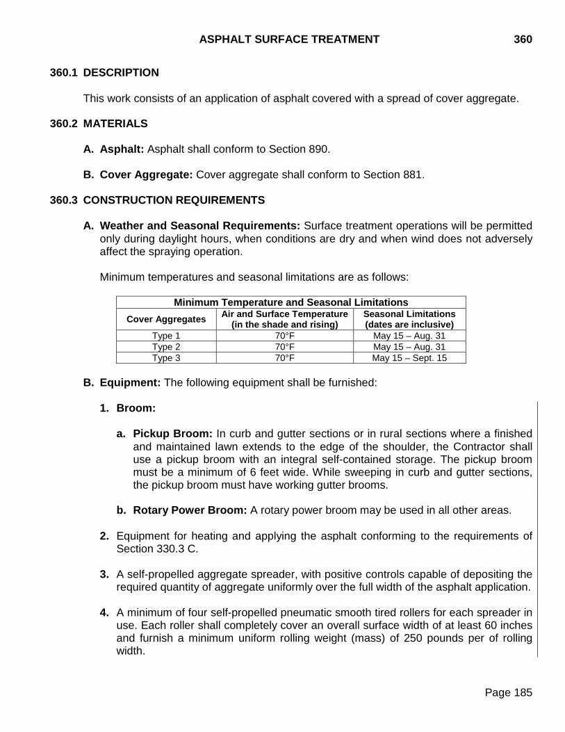
ASPHALT SURFACE TREATMENT 360
Page 185
360.1 DESCRIPTION
This work consists of an application of asphalt covered with a spread of cover aggregate.
360.2 MATERIALS
A. Asphalt: Asphalt shall conform to Section 890.
B. Cover Aggregate: Cover aggregate shall conform to Section 881. 360.3 CONSTRUCTION REQUIREMENTS
A. Weather and Seasonal Requirements: Surface treatment operations will be permitted only during daylight hours, when conditions are dry and when wind does not adversely affect the spraying operation. Minimum temperatures and seasonal limitations are as follows:
Minimum Temperature and Seasonal Limitations
Cover Aggregates Air and Surface Temperature (in the shade and rising)
Seasonal Limitations (dates are inclusive)
Type 1 70°F May 15 – Aug. 31 Type 2 70°F May 15 – Aug. 31 Type 3 70°F May 15 – Sept. 15
B. Equipment: The following equipment shall be furnished:
1. Broom:
a. Pickup Broom: In curb and gutter sections or in rural sections where a finished and maintained lawn extends to the edge of the shoulder, the Contractor shall use a pickup broom with an integral self-contained storage. The pickup broom must be a minimum of 6 feet wide. While sweeping in curb and gutter sections, the pickup broom must have working gutter brooms.
b. Rotary Power Broom: A rotary power broom may be used in all other areas.
2. Equipment for heating and applying the asphalt conforming to the requirements of
Section 330.3 C.
3. A self-propelled aggregate spreader, with positive controls capable of depositing the required quantity of aggregate uniformly over the full width of the asphalt application.
4. A minimum of four self-propelled pneumatic smooth tired rollers for each spreader in
use. Each roller shall completely cover an overall surface width of at least 60 inches and furnish a minimum uniform rolling weight (mass) of 250 pounds per of rolling width.
360 ASPHALT SURFACE TREATMENT
Page 186
C. Cover Aggregate Preparation: Following production of the cover aggregate stockpile and at least 14 calendar days prior to starting the asphalt surface treatment, the Contractor shall submit a sample of the cover aggregate to the asphalt supplier for evaluation of compatibility and design of the surface treatment. Prior to starting the surface treatment, the Contractor shall submit a copy of the compatibility test results and the asphalt surface treatment design from the asphalt supplier to the Engineer and the Department’s Bituminous Engineer. The Contractor shall notify the Area Office a minimum of 5 calendar days prior to sampling and submitting the cover aggregates. Satisfactory quality test results for the cover aggregate shall be obtained prior to use on the project.
D. Surface Preparation: The surface shall be thoroughly swept and cleaned of all foreign material. Appurtenances immediately adjacent to the surface to be treated shall be protected from the splatter of asphalt. The Contractor shall repair any damage to the satisfaction of the Engineer at no additional cost to the Department. Manhole covers, water shut valves, and other utility access points shall be covered to ensure liquid asphalt is not applied to them, as directed by the Engineer. The methods used for covering shall be removed after completion of the final asphalt surface treatment application. Freshly primed bases shall be cured prior to the application of surface treatments.
E. Application of Asphalt: The asphalt shall be maintained within a temperature range of
120°F to 180°F during application. Asphalt shall be applied by a pressure distributor in a uniform and continuous manner.
Unauthorized increases in the asphalt application rate will not be eligible for payment.
The angle of the spray nozzles and the height of the spray bar shall be set to obtain uniform distribution. When starting and stopping emulsion application, a strip of building paper or other suitable material, at least 3 feet in width and at least 1 foot longer than the width of the spray bar, shall be used to prevent a double application of emulsion. The distributor shall travel at the established speed when the spray bar is opened. Skipped areas and deficiencies shall be immediately corrected. Areas inaccessible to the distributor shall be satisfactorily covered by hand spray methods.
Spraying operations shall not proceed when it is evident the asphalt spread will not be covered with aggregate and rolled all in accordance with the prescribed schedule.
F. Application of Cover Aggregate: Cover aggregate shall be spread immediately
following application of all rapid-setting emulsions. For wind conditions of 5 miles per hour or less, the cover aggregate shall be spread within 5 minutes of the application of the medium-setting emulsion. For wind conditions greater than 5 miles per hour, the time may be reduced in the field to ensure the aggregate is applied before the medium setting emulsion breaks. Time limits for spreading of cover aggregate when using medium-setting emulsions shall be adjusted as directed to satisfy project conditions. The aggregate shall be applied before the emulsion begins to break (emulsion still brown in color).
ASPHALT SURFACE TREATMENT 360
Page 187
A complete aggregate coverage shall be continually maintained. A strip of asphalt application approximately 6 inches wide for a double overlap spray bar or 8 inches wide for a triple overlap spray bar, along that side of the spread forming a longitudinal joint with the adjacent spread shall be left uncovered. The adjacent asphalt and cover aggregate application shall overlap this strip. In lieu of this procedure a butt joint may be constructed using special end nozzles. Longitudinal joints, other than at centerline, will not be permitted within the center 24 feet unless otherwise approved by the Engineer. When loading trucks, the cover aggregate shall be screened to minimize segregation, eliminate oversize, and effectively break up or discard material bonded into chunks. When required, aggregate shall be uniformly moistened before or during loading. Unauthorized increases in application rates will not be eligible for payment. Prior to rolling, the contractor may be directed to adjust inequalities in the spread of Type 3 cover aggregate with a drag broom.
G. Rolling: Rolling shall begin immediately behind the spreader and shall consist of four
complete coverages using pneumatic tired rollers. A complete coverage is defined as rolling full width in one direction. The rolling shall be completed within 40 minutes after the cover aggregate is applied. Rollers shall be operated in unison at a close interval, and if the width of spread allows, in a staggered formation. Rollers shall not be operated at a speed in excess of 5 miles per hour. Asphalt and cover aggregate applications shall not extend more than 1/2 mile beyond the rolling operation. With the use of minimum specified equipment the project shall be completed in 1/2 mile increments, except for the sweeping of excess cover aggregate. The weight and tire pressures of the rollers shall be varied as directed to obtain optimum embedment of the cover material without undue crushing of the aggregate. Special attention shall be given to the transverse and longitudinal joints during rolling. Unsatisfactory joints shall be corrected without additional compensation. Turning of rollers on the freshly treated surface is prohibited. Rolling at night or when light conditions would create a traffic hazard will not be allowed.
H. Traffic Control: Construction operations shall be coordinated to minimize traffic delays.
One-way traffic shall be maintained during application of the surface treatment on driving lanes. Upon completion of rolling, traffic will be permitted to travel on the treated surface. Traffic shall be controlled by pilot cars and flaggers during application of the surface treatment on driving lanes with the speed of pilot cars not to exceed 20 miles per hour on the freshly applied surface treatment for a period of at least four hours after application.
The width, arrangement, and sequence of the parallel application strips shall not unduly inconvenience traffic.
I. Maintenance and Repair: Areas of the surface treatment, which peel or are otherwise
unsatisfactory, shall be repaired with additional asphalt, cover aggregate, and rolling.
360 ASPHALT SURFACE TREATMENT
Page 188
Compensation for repairs due to causes beyond the control of the Contractor will be paid at the contract unit price for asphalt surface treatment.
The finished surface treatment shall be uniform and smooth riding. Transverse or horizontal ridges, raveled spots, wheel marks, depressions, abrupt color changes, and other inequalities shall be corrected. Payment will not be made for this correction work. Asphalt splattered on roadway appurtenances shall be satisfactorily cleaned off by the Contractor. Loose material remaining on the surface shall be broomed off during a cool period within 24 hours of application. The brooming shall include the entire surface of the asphalt surface treatment application, additional lane widths, intersections, and shoulders. In curb and gutter sections and in areas where a finished and maintained lawn extends to the edge of the shoulder, the loose material shall be swept up with a pickup broom. Brooming the material into a pile with a rotary broom for pickup will not be allowed. In sections without curb and gutter and in areas where a finished and maintained lawn does not extend to the edge of the shoulder, the loose material may be swept onto the roadway inslopes, as approved by the Engineer.
Broomed off material picked up by the Contractor shall be disposed of at sites provided by the Contractor and approved by the Engineer.
360.4 METHOD OF MEASUREMENT
A. Asphalt for Surface Treatment: Asphalt for surface treatment will be measured to the nearest 0.1 ton.
B. Cover Aggregate: Cover aggregate will be measured to the nearest 0.1 ton.
360.5 BASIS OF PAYMENT
A. Asphalt for Surface Treatment: Asphalt for surface treatment will be paid for at the contract unit price per ton.
B. Cover Aggregate: Cover aggregate specified will be paid for at the contract unit price
per ton. Payment will be full compensation for furnishing, installing, and all incidentals required to complete the work.
COLD IN PLACE RECYCLING (CIR) OF ASPHALT CONCRETE 370
Page 189
370.1 DESCRIPTION
This work shall consist of milling asphalt pavement, mixing the reclaimed asphalt pavement (RAP) material with emulsified asphalt, placing the recycled mixture, and compacting the recycled mixture according to these specifications and the typical sections in the plans.
370.2 MATERIALS
A. Reclaimed Asphalt Pavement (RAP): Section 884. B. Asphalt: Section 890.
370.3 CONSTRUCTION REQUIREMENTS
A. Rollers: Pneumatic tired rollers shall have an effective roller weight (mass) of at least 250 pounds per inch of roller width or satisfactory vibratory compaction equipment. Tires shall be uniformly inflated so their air pressures will not vary by more than 5 psi. Rollers shall be operated with tire pressures and wheel loads within the manufacturer’s recommended range for the size and ply of the tire being used. Steel rollers shall furnish a minimum rolling weight of 275 pounds per inch of rolling width.
B. Equipment Configuration: The cold recycling equipment shall consist of a unit or a combination of units which will satisfactorily perform the following requirements: 1. Mill the bituminous pavement and pick up the RAP.
2. Process the RAP material to meet the specified gradation. The RAP material shall
be processed by a closed circuit system capable of continuously returning oversized material to the crusher.
3. Mix the RAP material uniformly with the specified amount of emulsified asphalt.
4. Deposit the mixture in a windrow or paver.
5. Place and compact the recycled mixture to the specified density with automatic line and grade controls.
C. Equipment Performance: The milling unit shall be capable of milling the asphalt concrete pavement at least 5 inches deep and a minimum of 12 feet wide in a single pass. The unit shall have automatic controls capable of maintaining uniform grade and cross slope.
The milling unit shall have a continuous weighing system with a meter to accurately measure the amount of water being added at the milling unit. The water pump shall shut off automatically if the milling unit is stopped.

370 COLD IN PLACE RECYCLING (CIR) OF ASPHALT CONCRETE
Page 190
The processing unit shall separate and remove strips of crack sealant from the RAP material prior to mixing and weighing. The mixing unit shall have a continuous weighing system for the processed RAP material, coupled with a meter to accurately maintain the proportion of RAP material and emulsified asphalt at the rate approved by the Engineer. The emulsified asphalt pump shall shut off automatically if delivery of RAP material is stopped. The mixing unit shall be capable of producing a homogeneous mixture of processed RAP material and emulsified asphalt without segregation. The emulsified asphalt metering system shall deliver the specified amount of asphalt to within 0.2% of the required application rate. Positive means shall be provided for calibration of the weighing and metering devices.
D. Milling and Mixing Operation: The RAP material shall be processed to the required gradation and thoroughly mixed with the specified amount of emulsified asphalt. Water may be added to the milling unit or to the RAP material to facilitate mixing, provided the water does not adversely affect the emulsified asphalt. The amount of moisture allowed in the recycled mixture shall be 3% or less prior to compaction. Results of the acceptance moisture test performed by the Department shall be recorded on a DOT-35 and shall be provided to the Contractor as soon as they are completed. The frequency of testing shall be performed at a minimum of one per 1/2 mile per lane processed. Moisture contents shall be determined by SD 108; Oven Drying Method or other method approved by the Engineer. The minimum sample size needed to determine the moisture content of the CIP material shall be 2000 grams. The recycled mixture shall be deposited in a windrow or paver without segregation. The Contractor shall have equipment available to equalize the windrow as directed.
E. Paving Operations: The recycled mixture shall be spread and compacted in a continuous operation confined to the minimum practical length. The laydown machine for the recycled mixture shall be controlled by an automatic system for controlling grade and slope and shall establish a longitudinal profile grade and transverse slope that is referenced from a traveling stringline. The traveling stringline shall utilize either mechanical skis or non-contacting grade averaging sensors. The traveling stringline shall have a minimum effective length of 28 feet. The system shall be capable of manually controlling the transverse slope. The recycled mixture shall be spread and finished in one lift by an asphalt concrete laydown machine. No heat shall be applied to the mixture by the laydown machine. The recycled mixture shall be placed and finished to within ±0.5% of the cross slope shown on the typical section sheet in the plans.
COLD IN PLACE RECYCLING (CIR) OF ASPHALT CONCRETE 370
Page 191
The quarter crown within any 12 foot transverse length (or actual lane width paved with a single paver pass) shall not exceed 0.04 feet when measured with a straight edge, stringline, or other suitable equipment.
F. Compaction and Density Requirements: Compaction and density requirement shall be a minimum of 97% of the target density. The target density shall be established in accordance with SD 219 and compacted under the following conditions: 1. The ambient air temperature is a minimum of 60°F and rising. 2. A minimum of one test strip shall be completed to determine the target density and
optimum sequence of rollers. The test strip(s) will remain in place as part of the completed work.
3. The depth of the lift shall be representative of the project. 4. The Contractor shall have, as a minimum, two self-propelled rollers for use on the
test strips (double drum vibratory steel roller and a pneumatic tired roller). When there is a significant change in mix proportions, weather conditions, equipment, or other controlling factors the Engineer may require construction of another test strip(s) to check target density.
G. Prime Coat Seal and Overlay: The compacted recycled mixture shall be primed prior to the overlay. The asphalt prime seal coat shall not be placed until the moisture content of the compacted recycled mixture is 2.0% or less. The prime coat and blotter material shall be applied as specified in the plans. The Contractor shall determine the amount of moisture in the compacted recycled mixture prior to proceeding with the prime coat seal. The moisture tests are for monitoring only and are not for acceptance. The frequency of testing shall be performed at a minimum of one per mile per lane processed. The Department will randomly determine sample locations at the determined frequency and ensure that the Contractor obtains samples by approved methods. The Contractor shall perform additional moisture tests on a weekly basis from the same area as the initial sample locations, until the compacted recycled mixture has reached specification. Results of the moisture tests shall be recorded on a DOT-35 and provided to the Engineer. Moisture content shall be determined by SD 108; Oven Drying Method or other method approved by the Engineer. The minimum sample size needed to determine the moisture content of the recycled material shall be 2000 grams. The Contractor, at no cost to the Department, shall patch all potholes and raveling of the prime and or compacted recycled mixture prior to paving.
370 COLD IN PLACE RECYCLING (CIR) OF ASPHALT CONCRETE
Page 192
H. Weather and Seasonal Limitations: Milling, mixing, and laydown of recycled mixture shall be completed only when: 1. The ambient air temperature is 60°F and rising.
2. Rain or foggy conditions do not exist.
3. The cold recycling shall only be performed as noted above from May 1 to September
15 (inclusive).
I. Traffic Control: Cold recycling activities will be permitted from sunrise to sunset. At the end of cold recycling activities each day, the Contractor shall open the roadway to normal two-way two-lane traffic. If recycling segments are incomplete at the end of the day the Contractor shall, at no additional cost, place granular material on the incomplete segment to provide a temporary driving surface which is stable and will drain free of standing water. All longitudinal vertical edges shall be beveled to a 12:1 slope with the temporary granular material.
370.4 METHOD OF MEASUREMENT
A. Cold in Place Recycling Asphalt Concrete: Cold in place recycling will not be measured. Plan quantity will be used unless the Engineer orders additional quantity in writing. Any additional quantity will be measured to the nearest square yard .
B. Asphalt for Cold Recycling: Asphalt for cold recycling shall be measured to the
nearest 0.1 ton.
370.5 BASIS OF PAYMENT
A. Cold in Place Recycling Asphalt Concrete: Cold recycling asphalt concrete will be paid for at the contract unit price per square yard. Payment will be full compensation for milling, water, water application, asphalt application, blending, laydown, compaction, and test strips including all equipment, labor, and incidentals required to satisfactorily complete the work.
B. Asphalt for Cold Recycling: Asphalt for cold recycling will be paid for at the contract
unit price per ton. Payment will be full compensation for the asphalt including all transportation, handling, storage, labor, and incidentals required.
PART D RIGID PAVEMENT 380
PORTLAND CEMENT CONCRETE PAVEMENT
Page 193
380.1 DESCRIPTION
This work consists of constructing Portland Cement Concrete Pavement of sufficient quality to serve the purpose for which the concrete pavement was designed on a prepared surface.
380.2 MATERIALS
Materials shall conform to the requirements specified in the following Sections:
A. Cement: Section 750. Type II cement shall be used for all concrete pavement.
B. Admixtures: Sections 751 and 752.
C. Water: Section 790.
D. Fine Aggregate: Section 800.
E. Coarse Aggregate: Section 820.
F. Reinforcing Steel: Section 1010.
G. Preformed Expansion Joint Filler: Section 860.
H. Joint Sealer: Section 870.
I. Curing Materials: Section 821.
J. Dowel Bar Assemblies: Section 1010.
K. Fly Ash: Sections 605 and 753. L. Epoxy Resin Adhesive: Epoxy resin adhesive shall be of the type intended for horizontal
applications, and shall conform to the requirements of ASTM C881, Type IV, Grade 3 (equivalent to AASHTO M 235, Type IV, Grade 3) Class A, B, or C. The minimum gel time shall be 5 minutes.
380.3 CONSTRUCTION REQUIREMENTS
A. Quality of Concrete and Proportioning: When the Contractor proposes to use aggregate from sources not previously tested by the Department, the Contractor shall submit preliminary samples to the Department’s Central Materials Laboratory to determine its acceptability.
380 PORTLAND CEMENT CONCRETE PAVEMENT
Page 194
If a concrete mix design is not designated in the plans, the Contractor shall develop and use a concrete mix design conforming to the following for approval by the Department:
• Minimum cementitious material content of 600 pounds with a fly ash content
of 20 to 25%. • Minimum coarse aggregate content of 55% by weight of total aggregates. • Minimum 28 day compressive strength of 4,000 psi.
The Department’s Concrete Engineer will determine if a concrete mix design verification is required. If the Department, in the Department’s sole discretion, determines a concrete mix design verification is required, the Contractor shall submit samples of materials proposed for use, excluding water, to the Department’s Central Materials Laboratory at least 40 calendar days prior to the anticipated paving start date. Aggregate samples shall be obtained from stockpiles of material to be used in the work. A maximum of two concrete mix design verifications per contract will be made by the Department without charge. Should the Contractor desire additional concrete mix designs verified, the costs involved shall be at the Contractor's expense.
The concrete paving mix shall have a uniform consistency and shall be proportioned as set forth in the approved design mix.
For the stationary side form method, the slump of the concrete shall be between 1 inch and 3 inches. For the slip-form method, the slump of the concrete shall not be more than 2 inches. The concrete shall contain 6.5% entrained air with an allowable tolerance of +1% to -1.5%. Air shall be entrained by an approved air-entraining admixture.
B. Equipment: Vehicles tracking foreign substances, including but not limited to; soil, rock,
vegetation, hardened concrete, partially hydrated concrete, fuel, and oil will not be allowed to drive through or back into fresh mixed concrete. Equipment dropping foreign substances, including but not limited to; soil, rock, vegetation, hardened concrete, partially hydrated concrete, fuel, and oil from the unit shall not be allowed over or in contact with the fresh mixed concrete.
1. Batching Equipment: Batching equipment shall be computerized and automatic.
Manual operation will be permitted when automatic controls fail provided concrete meeting specified results is produced, however, the automatic operation shall be restored before work may commence the day following the failure.
The Contractor shall provide satisfactory means for obtaining material samples from the batching plant. Batching plant structures shall be leveled so the accuracy of the weighing mechanism is maintained.
PORTLAND CEMENT CONCRETE PAVEMENT 380
Page 195
Hoppers shall fully discharge without jarring the scales. Clearances between scale parts, hoppers, and bin structure shall be maintained to avoid displacement of, or friction between, parts due to material accumulations, vibration, or other cause. Pivot mountings shall be designed so the parts will not jar loose and constructed to assure unchanging spacing of knife edges under all circumstances. Exposed fulcrums, clevises, and similar working parts shall be kept clean. To maintain accuracy, weighing hoppers and other parts which are affected by wind action shall be protected by shelters or wind breaks. The equipment for weighing aggregates, cement, water, and admixtures shall be an integral part of the batching equipment. The scales/load cells shall be accurate within 0.5% at any point throughout the range of the scale/load cell. Graduations shall be not greater than 0.1% of the capacity of the scale/load cell. The scales/load cells shall be sensitive to the weight indicated by one graduation. The following controls shall apply to the aggregate batching equipment:
The batching equipment shall operate within a delivery tolerance of 1.5% of the net weight for each aggregate weighed. The hopper inlet mechanism shall be interlocked against opening when the discharge gate is open.
The hopper discharge mechanism shall be interlocked against opening while the hopper is being charged.
The hopper discharge mechanism shall be interlocked against opening if any material in the hopper is either overweight or underweight by more than 1.5% of the specified weight.
The cement batching equipment shall operate within a delivery tolerance of 1% of the net weight of the cement per batch. The cementitious material (cement and fly ash) batching equipment shall also operate within a delivery tolerance of 1% of the net weight of the total cementitious material per batch. Water may be measured by volume or weight. The measuring equipment shall operate within a delivery tolerance of 1% of the net weight or volume of water. When water is measured by volume, means for determining the accuracy of the measuring device shall be provided. Air-entraining or other admixtures may be measured by volume or by weight. The measuring equipment shall operate within a delivery tolerance of 3% of the net weight or volume per batch.
380 PORTLAND CEMENT CONCRETE PAVEMENT
Page 196
2. Ticket Requirements: A printed, computer generated, ticket shall be automatically produced for each load of concrete batched. The printed computer ticket shall accompany each load of concrete to the project and shall be presented to the Engineer prior to discharging the load at the project site unless the Engineer approves an alternate procedure. The printed ticked must contain the following minimum information: Truck Number Date and Time Batched Total volume of the load, in cubic yards DOT Mix Design Number Actual weight (mass) or volume of each component of the mix:
Coarse Aggregate Fine Aggregate Cement Fly Ash Water (batch water) Admixtures
Air Entraining Admixtures Water Reducers Retarders Accelerators Others
% Moisture in Aggregate (either % free moisture or % total moisture) Maximum Water Allowed
(maximum water allowed = weight of mix design water - weight of free water) W/C ratio (as-batched) When automatic moisture sensing equipment is used for an aggregate component, the batch ticket shall show the percent of moisture for the aggregate component with moisture sensing equipment. The results of the most recent two hour moisture test shall be shown for aggregate components without moisture sensing equipment. The final W/C ratio, for acceptance, shall be calculated using the following formula and rounded to the nearest 0.01:
+
++=
material uscementitioary supplement of weight cement ofweight
wateradded of weight r batch wate of weight water free ofweight ratio W/C
% free moisture = % total moisture in aggregate - % absorption of aggregate weight of free water = % free moisture x weight of aggregate weight of batch water = total weight of water added to the batch either at the plant or in the
truck weight of added water = total weight of water added after batching process (typically added at
point of delivery)
PORTLAND CEMENT CONCRETE PAVEMENT 380
Page 197
The weight of free water shall be calculated for both the fine aggregate and the coarse aggregate. The above information must be automatically printed in such a manner that the Engineer may verify the mix adheres to the proportions specified by the mix design.
3. Mixing and Hauling Equipment: Mixers and agitators shall have attached in a
prominent place, the manufacturer's plate showing the various uses for which the equipment is designed and the capacity of the drum in terms of volume of mixed concrete.
The pick-up and throw-over blades in the drum shall be restored or replaced when any part or section is worn 3/4 inch or more below the original height of the manufacturer's design. The Contractor shall maintain a copy of the manufacturer's design, showing dimensions and arrangement of blades in reference to the original height and depth. Mixers that have an accumulation of hard concrete or mortar shall not be used. Mixers, except truck mixers, shall be equipped with a timing device to track the total mixing time of the concrete batch. Truck mixers shall be equipped with counters to record the number of revolutions of the drum or blades. Mixers shall be capable of combining the concrete ingredients into a thoroughly mixed and uniform mass and shall uniformly discharge the concrete. The hauling bodies of non-agitating equipment shall be smooth, mortar-tight metal containers equipped with gates and vibrators that will permit uniform control of the discharge of the concrete.
4. Spreading and Finishing Equipment: The spreading equipment shall consist of a mechanized device to place and provide a rough strike off of the concrete. The concrete shall be unloaded into an approved mechanical concrete spreader and deposited uniformly across the subgrade or subbase as close as possible to its final position. The use of a mechanical spreader may be waived provided the concrete hauling equipment is equipped with a discharge system capable of distributing the concrete uniformly without segregation across the width of paving and meets the approval of the Engineer. The spreader shall run on forms when forms are used or on wheels or tracks when slip forming. The mechanical concrete spreader shall be self-propelled and shall be capable of spreading the concrete mix to the desired cross sections. The spreader shall be easily adjustable to spread different elevations of concrete.
Slipform paving equipment shall have the direction of forward motion and grade (vertical elevation) controlled by an electronic sensing device. The electronic sensing device shall either follow a taut string line or shall be controlled by a GPS/Total
380 PORTLAND CEMENT CONCRETE PAVEMENT
Page 198
Station system capable of meeting the alignment, grade, surface test, and cross slope requirements. The paving equipment shall spread, consolidate, screed, and finish the freshly placed concrete to provide a dense and homogenous pavement with a minimum amount of hand finishing. The paving equipment shall not cause flotation of aggregate particles or show evidence of an accumulation of laitance on the surface of the concrete either during or after placement.
5. Vibrators: Vibrators shall be either the surface pan type or the internal type. They may be attached to the spreader, the finishing machine, or mounted on a separate carriage. Vibrators shall be interlocked with the machine's travel mechanism so vibration is stopped when the forward motion stops. Vibrators shall not come in contact with the joints, load transfer devices, reinforcement, subgrade, subbase, or side forms.
The frequency of the surface vibrators shall not be less than 3,500 impulses per minute. The frequency of the internal vibrators shall not be less than 7,000 impulses per minute. When spud type internal vibrators are used adjacent to forms they shall have a frequency of not less than 3,500 impulses per minute. Vibrators shall not be operated in excess of this frequency to such a degree that flotation of aggregate particles is caused and is evident or visible either during or after placement or that it causes an accumulation of laitance on the surface of the concrete. A vibrating reed tachometer, hand type, shall be provided with each paver. The vibrating reed tachometer shall have a range from at least 4,000 to 10,000 vibrations per minute (VPM). For a contract which has a minimum of 50,000 square yards of pavement that is 12 feet or more wide, an electronic internal vibrator monitoring device shall be provided. The device shall be capable of displaying the operating frequency of each internal vibrator, and shall be visible to the paving operator. The vibrator monitoring device shall have a range from at least 4,000 to 10,000 VPM. Vibrators shall not be used to level or spread the concrete, but shall be used only for purposes of consolidation.
6. Concrete Saw: The Contractor shall provide sawing equipment, adequate to complete the sawing to the required dimensions and at the required rate. The Contractor shall also provide at least one standby saw in good working order. If an early entry saw is used, the early entry saw shall use a dry cutting operation with up cutting blade rotation and a skid plate straddling the blades to minimize raveling and tearing of the concrete at the joint.
PORTLAND CEMENT CONCRETE PAVEMENT 380
Page 199
7. Forms: Forms shall have a depth not less than the prescribed edge thickness of the
pavement. Built up forms with horizontal joints shall not be used. When staked in place, forms shall withstand the pressure of the concrete and the impact, vibration and loading of any equipment they are required to support, without significant springing, settlement, or lateral displacement meeting the following requirements: The top face of any form shall not vary from a true plane by more than 1/8 of an
inch in 10 feet, nor shall the contact face of a straight form vary from a true plane by more than 1/4 inch in 10 feet.
Bent, twisted, or broken forms and those with battered top surfaces shall be removed from the work. Repaired forms shall not be used until inspected and approved. Flexible or curved forms of proper radius shall be used for curves of 100 foot radius or less. Flexible or curved forms shall be of an acceptable design.
8. Profilograph: When specified in the Contract, the Contractor shall furnish and operate an approved 25 foot California style profilograph. The profilograph shall consist of a 25 foot frame supported upon a multiple system of wheels at both ends. The profile shall be recorded from the vertical movement of a wheel, attached to the frame at midpoint, in reference to the mean elevation of the points of contact established by the support wheels. The profilogram (trace) shall be recorded on a scale of 1 inch is equal to 25 feet longitudinally and 1 inch equal to 1 inch vertically.
The Contractor shall supply and use a computerized California type profilograph. The computer shall smooth the profile with a third-order Butterworth filter with a cutoff wavelength of 2.0 feet. The computer shall generate a profile index using a zero width blanking band. The computer shall also use a 0.3 inch bump threshold to identify “must grind” locations. Prior to use on the project and periodically thereafter, the calibration of the profilograph shall be checked. The vertical and horizontal scales shall be checked. The horizontal scale shall be checked by running the profilograph over a known distance and scaling the results on the profilogram. The cause of incorrect scales shall be determined and corrected prior to using the profilograph.
C. Preparation:
1. Insert Steel Bar in PCC Pavement: When specified in the plans and at the locations specified in the plans, the Contractor shall insert steel bars into drilled holes in the existing concrete pavement. An epoxy resin adhesive must be used to anchor the steel bar in the drilled hole. Epoxy resin adhesive shall conform to Section 380.2 L.
380 PORTLAND CEMENT CONCRETE PAVEMENT
Page 200
The diameter of the drilled holes in the existing concrete pavement for the steel bars shall not be less than 1/8 inch nor more than 3/8 inch greater than the overall diameter of the steel bar. Holes drilled into the existing concrete pavement shall be located at mid-depth of the slab and true and normal. The drilled holes shall be blown out with compressed air using a device that will reach to the back of the hole to ensure that all debris or loose material has been removed prior to epoxy injection. The Contractor shall mix the epoxy resin as recommended by the manufacturer and apply by an injection method approved by the Engineer. If an epoxy pump is utilized, the pump shall be capable of metering the components at the manufacturer’s designated rate and be equipped with an automatic shut-off. The pump shall shut off when any of the components are not being metered at the designated rate. The Contractor shall fill the drilled holes 1/3 to 1/2 full of epoxy, or as recommended by the manufacturer, prior to insertion of the steel bar. Care shall be taken to prevent epoxy from running out of the horizontal holes prior to steel bar insertion. Rotate the steel bar during insertion to eliminate voids and ensure complete bonding of the bar. Insertion of the bars by the dipping method will not be allowed.
2. Stationary Side Form Method: Forms shall be set to line and grade. The granular surface shall be final graded and dowel assemblies, if required, accurately placed in advance of concrete placement.
The foundation under the forms shall be compacted and true to grade. The form shall be firmly in contact with the granular surface for the entire length of the form. Forms shall be staked into place with not less than three pins for each 10 foot section. A pin shall be placed at each side of every joint. Form sections shall be tightly locked and free from play or movement. Forms shall be cleaned and oiled prior to placing concrete. Alignment and grade elevations of the forms shall be checked and corrections shall be made before placing concrete. When forms have been disturbed or the grade has become unstable, the forms shall be reset and rechecked. After side forms have been set to line and grade and securely fastened, the surface on which the concrete paving is to be placed shall be brought to final grade by a subgrader or subgrade plainer. High areas shall be trimmed to proper elevation. Low areas shall be filled and compacted to a condition similar to that of surrounding grade, or filled with concrete integral with the pavement. An automatic subgrader operating from a preset grade line or automatic grade control may be used prior to setting of the side forms. After grading has been completed by the automatic subgrader, the forms shall be set, the surface checked, and high and low areas corrected.
PORTLAND CEMENT CONCRETE PAVEMENT 380
Page 201
The finished subgrade surface shall be maintained in a smooth and compacted condition until the pavement is placed.
3. Slip Form Method: The surface, on which the concrete is to be placed, shall be brought to final grade by an automatic subgrader operating from a preset grade line or automatic grade control. The finished subgrade surface shall be maintained in a smooth and compacted condition until the pavement is placed.
D. Handling, Measuring, and Batching Materials: The separate aggregate components
shall not become intermixed prior to being weighed. Aggregates shall be transported from stockpiles or other sources to the batching plant in a manner that maintains a uniform grading of the material. The use of track-type dozing equipment will not be permitted in handling coarse aggregates from stockpiles.
Aggregates that have become segregated or mixed with earth or foreign material shall not be used. If the aggregates contain non-uniform moisture, storage or stockpile periods will be required to equalize the moisture content.
The separate aggregate components for each batch may be weighed cumulatively in a single hopper or weighed separately in individual hoppers. A separate scale and hopper shall be used for weighing cementitious materials. The quantity of cement and fly ash used versus the quantity specified will be checked periodically by running a cutoff. The Contractor shall completely empty the cement silo and necessary conveyances at the direction of the Engineer. Individual cutoffs shall not show an underrun exceeding 1.5%, nor shall the final cutoff show an overall underrun exceeding 1.0%. The cutoff will not be performed if concrete is supplied by a commercial redi-mix plant also supplying concrete to non SDDOT projects at the same time. The amount of batch water and aggregates added to the mix shall be adjusted accordingly using the results of the most recent two hour moisture tests. If automatic moisture sensing equipment is used, the Engineer may allow the use of the automatic moisture sensing results to make adjustments.
E. Mixing Concrete: Concrete shall be mixed at a central stationary plant. Truck mixing will be permitted only when approved by the Engineer.
Mixing and agitating speeds shall be as designated by the manufacturer of the equipment. Mixers may not be charged in excess of their rated capacity. Manual operation of the central plant will be permitted only in case of failure of the automatic control. Automatic operation must be restored before work may commence the day following the failure.
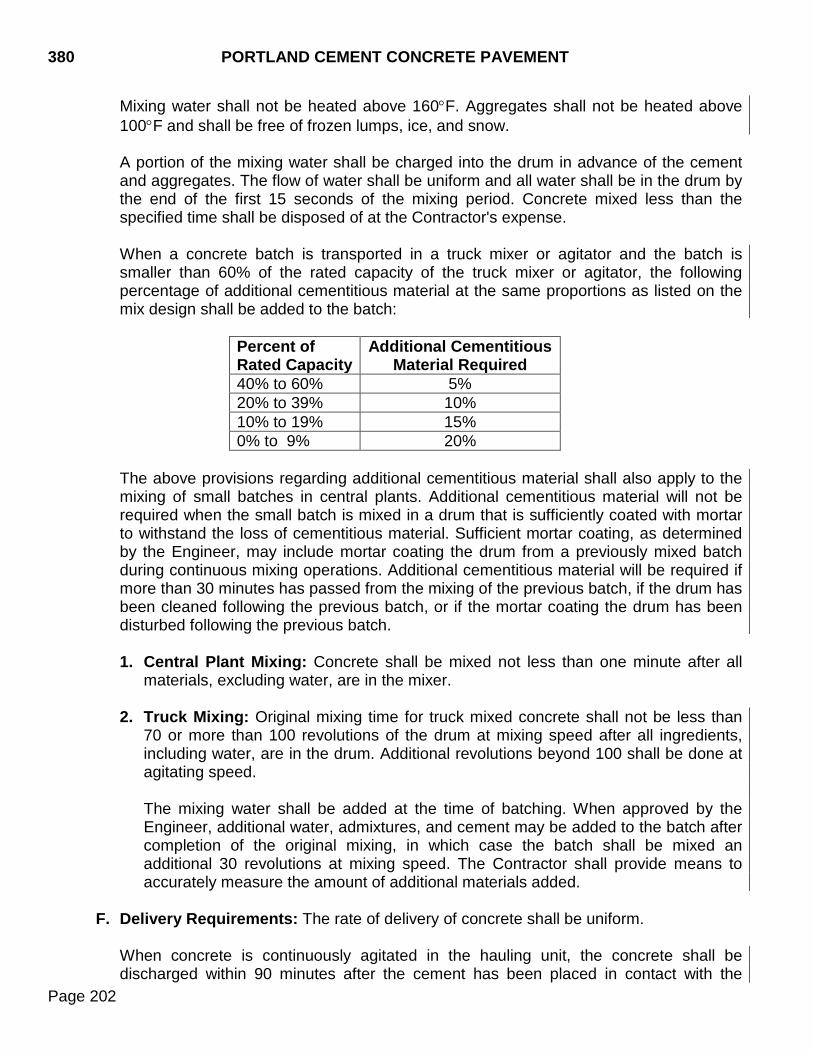
380 PORTLAND CEMENT CONCRETE PAVEMENT
Page 202
Mixing water shall not be heated above 160°F. Aggregates shall not be heated above 100°F and shall be free of frozen lumps, ice, and snow.
A portion of the mixing water shall be charged into the drum in advance of the cement and aggregates. The flow of water shall be uniform and all water shall be in the drum by the end of the first 15 seconds of the mixing period. Concrete mixed less than the specified time shall be disposed of at the Contractor's expense. When a concrete batch is transported in a truck mixer or agitator and the batch is smaller than 60% of the rated capacity of the truck mixer or agitator, the following percentage of additional cementitious material at the same proportions as listed on the mix design shall be added to the batch:
Percent of Rated Capacity
Additional Cementitious Material Required
40% to 60% 5% 20% to 39% 10% 10% to 19% 15% 0% to 9% 20%
The above provisions regarding additional cementitious material shall also apply to the mixing of small batches in central plants. Additional cementitious material will not be required when the small batch is mixed in a drum that is sufficiently coated with mortar to withstand the loss of cementitious material. Sufficient mortar coating, as determined by the Engineer, may include mortar coating the drum from a previously mixed batch during continuous mixing operations. Additional cementitious material will be required if more than 30 minutes has passed from the mixing of the previous batch, if the drum has been cleaned following the previous batch, or if the mortar coating the drum has been disturbed following the previous batch.
1. Central Plant Mixing: Concrete shall be mixed not less than one minute after all
materials, excluding water, are in the mixer.
2. Truck Mixing: Original mixing time for truck mixed concrete shall not be less than 70 or more than 100 revolutions of the drum at mixing speed after all ingredients, including water, are in the drum. Additional revolutions beyond 100 shall be done at agitating speed.
The mixing water shall be added at the time of batching. When approved by the Engineer, additional water, admixtures, and cement may be added to the batch after completion of the original mixing, in which case the batch shall be mixed an additional 30 revolutions at mixing speed. The Contractor shall provide means to accurately measure the amount of additional materials added.
F. Delivery Requirements: The rate of delivery of concrete shall be uniform.
When concrete is continuously agitated in the hauling unit, the concrete shall be discharged within 90 minutes after the cement has been placed in contact with the
PORTLAND CEMENT CONCRETE PAVEMENT 380
Page 203
aggregates and discharged and screeded within 105 minutes. When the concrete temperature is 85°F or above, the time limitation shall be reduced to discharged within 45 minutes and discharged and screeded within 60 minutes. When concrete is not continuously agitated in the hauling unit, the concrete shall be discharged within 45 minutes after the cement has been placed in contact with the aggregates and discharged and screeded within 60 minutes. When the concrete temperature is 80°F or above, the time limitation shall be reduced to discharged within 30 minutes and discharged and screeded within 45 minutes.
The hauling unit shall be thoroughly cleaned and flushed with water as necessary to insure hardened concrete will not accumulate in the concrete hauling compartment. All wash water shall be completely discharged before recharging the hauling unit with fresh concrete.
G. Placing Concrete: Placement of concrete on a frozen surface will not be permitted.
The surface temperature of forms, steel, and adjacent concrete which will come in contact with the concrete shall be raised to a temperature above freezing prior to placement.
Concrete temperature at time of placement shall not be less than 50°F or more than 90°F.
The subgrade surface shall be uniformly moist when the concrete is placed. Moisture shall be applied without forming pools of water. The concrete shall be deposited on the grade so as to require as little rehandling as possible. Free fall of concrete shall not exceed 5 feet.
Necessary hand spreading shall be done with shovels. Rakes or vibrators shall not be used for spreading concrete. Workmen shall not be allowed in the freshly mixed concrete with boots or shoes coated with foreign substances. The concrete shall be consolidated against and along the faces of all forms by vibrators. Vibrators shall not come in contact with a joint assembly, the grade, or a side form. The vibrator shall not be operated longer than 10 seconds in any one location.
All concrete material which falls on or is worked into the surface of a completed slab shall be removed immediately.
H. Test Specimens: The Contractor shall furnish concrete from the mixture for making test
specimens.
I. Placement of Reinforcement and Dowel Bar Assemblies: The reinforcement shall be free from dried concrete, dirt, oil, paint, grease, mill scale, and rust which could impair bond with the concrete. Epoxy coated dowel bars and tie bars shall meet the requirements of Section 480.3 A.
380 PORTLAND CEMENT CONCRETE PAVEMENT
Page 204
The reinforcement shall be positioned on approved supports in advance of the concrete placement. No hand placement will be allowed. Automatic dowel bar inserters will not be allowed. The use of an automatic tie bar inserter mounted at the back of the paving pan will only be allowed on the vertical edge of longitudinal construction joints. The Concrete shall be consolidated around the tie bar. The use of an automatic tie bar inserter will not be allowed on sawed longitudinal joints. Tie bars shall be held in the specified position parallel to the slab surface and perpendicular to the centerline by a supporting device. Tie bars or tie bar baskets shall be securely staked to the roadbed and shall hold the bar at the correct spacing, alignment, and elevation. Tie bars will not require supports if inserted into the side of the pavement during slip form paving of the longitudinal construction joint operation. Failure to acquire the correct tie bar locations or position in the construction joint shall require the bars to be corrected and a change made to the operation which may include drilling and epoxying bars or other methods as approved by the engineer. The final position of each tie bar shall be within the following tolerances:
Vertical Placement: ±T/6 for any part of the tie bar (T = slab thickness) Transverse Placement (side shift): ±3 inches when measured perpendicular to the longitudinal joint line
If the tie bar does not meet the requirements and tolerances specified, corrective action shall be performed at the Contractor’s expense to the satisfaction of the Engineer. Dowel bar assemblies shall be installed where specified. Anchor pins for the dowel bar assemblies shall be installed as detailed in the plans. Dowel bar assemblies shall be fabricated in single units for the appropriate lane prior to being placed on the subgrade. After the dowel bar assemble is staked and prior to concrete installation, it is the Contractor’s option to cut and bend spacer wires that pass through the contraction joint.
The free ends of the epoxy coated dowel bars [minimum of 1/2 of the dowel length plus 2 inches] shall be given a thin uniform coating of form oil or multipurpose grease. This coating shall be applied within two hours of being covered by concrete. In lieu of this manual coating, dowel bar assemblies may be pre-coated by dipping the complete assembly in a bond breaker meeting the requirements of Section 1010. Dowel bar assemblies shall be pre-coated on projects which have quantities of Portland cement concrete pavement of 50,000 square yards or greater. Pre-coated dowel bar assemblies must be free of foreign materials at the time of placement. Dowel bars shall be placed parallel to the subgrade and parallel to the centerline of the pavement as specified in the plans. The final position of each dowel bar shall be within the following tolerances:
PORTLAND CEMENT CONCRETE PAVEMENT 380
Page 205
Vertical Placement: ±1/8 inch for any part of the dowel bar Transverse Placement (side shift): ±1/2 inch when measured perpendicular to the longitudinal joint line
If the dowel bar does not meet the requirements and tolerances specified, corrective action shall be performed at the Contractor’s expense to the satisfaction of the Engineer. The Contractor shall accurately mark the location of doweled contraction joints to assure accurate placement of the weakened plane of the joint during subsequent operations. The marks must be within 1 inch of the center of the dowel bars as placed.
Reinforcement for continuously reinforced concrete slabs shall be supported on chairs and the entire slab poured in one operation. The chairs meeting the requirements of Section 480 shall hold the reinforcement in position without displacement during concrete placement. In addition to other inspection methods for reinforcement and dowel bar assemblies, the Department may use a Ground Penetrating Radar (GPR) to verify reinforcement and dowel bar locations in the hardened concrete. The GPR may be used any time prior to the Acceptance of Field Work being issued. All costs related to corrective measures, including but not limited to concrete removal or cutting of reinforcement, price deducts, and delays to the project schedule shall be the responsibility of the Contractor.
J. Final Strike-Off, Consolidation, and Finishing:
1. Sequence: The sequence of operations shall be; the strike-off and consolidation,
floating and removal of laitance, straight edging, and final surface finish.
The addition of water to the surface of the concrete to assist in finishing operations will not be permitted. In isolated areas where extreme conditions exist, the Engineer may determine the addition of water would be beneficial if applied with an approved fog sprayer. Concrete shall be finished before initial set has occurred. Concrete not finished before initial set has begun shall be wasted. Retempering of concrete will not be allowed. Concrete shall not be mixed and placed unless natural light is sufficient for finishing operations. The Contractor shall remove and replace concrete placed that is not workable or able to be finished properly. The concrete shall be struck-off, consolidated, and finished, so the surface of the pavement conforms to the cross section and elevation specified. The Contractor shall consolidate the concrete in a manner that results in a dense homogenous mass without segregation, holes, voids, or layers. Concrete shoulders shall not be constructed above or more than 1/8 inch lower than adjacent concrete pavement.
380 PORTLAND CEMENT CONCRETE PAVEMENT
Page 206
2. Finishing at Joints: The concrete adjacent to joints shall be placed without voids or segregation against the joint material, under and around all load transfer devices, joint assembly units, and other features designed to extend into the pavement. Concrete adjacent to joints shall be mechanically vibrated as per Section 380.3 G.
3. Machine Finishing: Vibrators meeting the requirements of Section 380.3 B.5 shall
be used for full width vibration of concrete paving slabs.
Immediately after placement, the concrete shall be struck off and screeded by an approved finishing machine. The machine shall go over each area of pavement as many times and at the intervals necessary to produce a surface of uniform texture, to provide proper consolidation, and to provide a dense homogenous mixture free of segregation, holes, voids, and layers. The Contractor will be responsible to remove and replace pavement that is not properly consolidated or contains segregation, holes, voids, and layers.
Excessive finishing over a given area shall be avoided. The top of the forms shall be kept clean by an effective cleaning device attached to the machine. The travel of the machine on the forms shall be maintained true without lift, wobbling, or other variation affecting the precision finish.
During the first pass of the finishing machine, a ridge of concrete shall be maintained ahead of the front screed for its entire length.
The finishing machine shall be operated with a continuous forward movement. All operations of mixing, delivering, spreading, and vibrating concrete shall be coordinated to provide uniform progress and minimize the stopping and starting of the paver. Except in an emergency, no tractive force shall be applied to the machine, except that which is controlled from the machine.
4. Hand Finishing: Hand finishing methods will not be permitted except when narrow
widths or irregular areas that cannot be finished with mechanical equipment are encountered.
In the event of mechanical equipment breakdown, the concrete already deposited on the grade shall be hand finished and additional concrete placement shall be terminated. Hand finishing shall be done in a manner that produces an acceptable finished surface.
5. Floating: Long handled floats shall be used to smooth and fill open-textured areas
in the pavement. The use of long-handled floats shall be kept to a minimum and shall not be used to float the entire surface of the pavement. Care shall be taken so the crown is not worked out of the pavement during the operation.
PORTLAND CEMENT CONCRETE PAVEMENT 380
Page 207
Excess water and laitance shall be removed from the surface of the pavement by a straightedge 10 feet or more in length. Successive drags shall be lapped 1/2 the length of the straightedge.
6. Final Finish: Before the concrete has attained its initial set, the surface shall be
given a final finish with a carpet drag drawn over the surface in a longitudinal direction. The drag shall be mounted on a bridge and shall be sized so that a strip of the carpet at approximately 2 feet wide is in contact with the pavement surface while the drag is operated.
The condition of the drag shall be maintained so the resultant surface is of uniform appearance with corrugations approximately 1/16 inch in depth. Drags shall be maintained clean and free of encrusted mortar. Drags that cannot be cleaned shall be discarded and replaced.
The carpet shall meet the following requirements:
Facing Material ............................................. Molded polyethylene pile face Blade Length ................................................................... 7/8 inch, ±1/8 inch Total Fabric Weight ........................... 70 ounces per square yard minimum
The backing shall be of a strong, durable material, not subject to rot, which is adequately bonded to the facing.
Plain Jointed concrete pavement shall be either longitudinally or transversely tined as specified in the plans. Continuously reinforced concrete pavement shall be longitudinally tined. Tining depth and spacing shall be determined according to SD 418. Brooming may be used on irregular areas in lieu of the carpet drag and tine finish. The broom shall be drawn transversely across the pavement with adjacent strokes slightly overlapping. Brooming shall be uniform in appearance and shall produce grooves approximately 1/16 inch deep. Texturing shall be completed while the concrete surface can be broomed without being torn or unduly roughened by the operation. The finished surface shall be free from rough and porous areas, irregularities, and depressions resulting from improper handling of the broom. a. Transverse Tining: Immediately following the carpet drag, the surface of the
concrete pavement shall be given a transverse metal-tine finish with a separate self-propelled mechanical device. The metal-tine finish shall provide a groove width of 1/8 inch and a groove depth of 6/32 inch ± 2/32 inch. The spacing between the individual tines shall meet the following:
380 PORTLAND CEMENT CONCRETE PAVEMENT
Page 208
Inches (ten foot tining rake) 2-5/16, 2-15/16, 1-1/4, 2-7/16, 2-1/16, 1-1/4, 13/16, 1, 1-5/16, 1-1/8, 2-5/16 2-1/2, 2-7/8, 2-3/4, 1-1/8, 2-3/4, 2-1/8, 1-15/16, 13/16, 7/8, 2-5/8, 3-1/16 3-1/16, 7/8, 9/16, 9/16, 1-5/8, 2-3/8, 1, 1-1/4, 1-9/16, 2-15/16, 1-1/8 1-15/16, 2-3/16, 2, 2-13/16, 1, 2-11/16, 13/16, 1-7/8, 9/16, 2-5/16, 1-7/8 2-1/2, 1-5/16, 3-3/16, 1-3/8, 15/16, 7/8, 1-5/8, 9/16, 1-3/4, 2-7/8, 3 1-5/8, 1-5/8, 7/8, 9/16, 5/8, 2-13/16, 1-5/8, 2-7/16, 13/16, 1-1/4, 11/16 2-3/4, 2-5/16, 1-1/8 Successive passes of the tining shall not overlap. Each location, where transverse joint saw cuts are to be made, shall be protected from tining by covering with a metal strip from 4 inches to 6 inches or by other methods that produce acceptable results. Brooming may be used on irregular areas in lieu of the carpet drag and tine finish. The broom shall be drawn transversely across the pavement with adjacent strokes slightly overlapping. Brooming shall be uniform in appearance and shall produce grooves 1/16 inch deep. Texturing shall be completed while the concrete surface can be broomed without being torn or unduly roughened by the operation. The finished surface shall be free from rough and porous areas, irregularities, and depressions resulting from improper handling of the broom.
b. Longitudinal Tining: Immediately following the carpet drag, the surface of the concrete pavement shall be given a longitudinal metal-tine finish with a wire broom or comb attached to a separate self-propelled mechanical device. Transverse joints shall not be protected from longitudinal tining; the tining shall be continuous across the joints. The slab shall not be tined within 3 inches of the edge of the slab, centerline, or rumblestrip. The longitudinal tining equipment shall have the ability to be raised and lowered, and shall have vertical and horizontal controls to ensure straight grooves that are parallel to the longitudinal joint. The tine bar shall have a single row of tines and shall provide a groove width of 1/8 inch ±1/64 inch and a groove depth of 6/32 inch ± 2/32 inch. The spacing between the individual tines shall be uniformly spaced at 3/4 inch intervals.
7. Edging at Forms and Joints: After the final finish, and while the concrete is still
plastic, the edges of the pavement along each side of the slab, and on each side of transverse construction joints, shall be worked with an approved tool and rounded to
PORTLAND CEMENT CONCRETE PAVEMENT 380
Page 209
the specified radius. Edging will be permitted along longitudinal construction joints provided the radius does not exceed 1/4 inch. A well-defined and continuous radius shall be produced and a smooth, dense mortar finish obtained. The surface of the slab shall not be unduly disturbed by tilting of the tool during use.
Any tool marks appearing on the slab adjacent to the joints shall be eliminated by brooming, belting, or burlap dragging the surface without disturbing the rounding of the corner of the slab. Where preformed expansion joint filler is used, the Contractor shall remove all concrete on top of the preformed expansion joint filler. All joints shall be tested with a 10 foot straightedge before the concrete has set and correction made if one side of the joint is higher than the other or if they are higher or lower than the adjacent slabs.
K. Protection of Concrete: For the protection of the pavement surface, the Contractor
shall have available covering materials, including but not limited to, insulating blankets, curing blankets, and plastic sheeting. The Contractor shall maintain the concrete surface temperature above 35°F until the concrete has attained a compressive strength of at least 1,500 psi. In addition, when the air temperature is forecasted to be below 32°F for more than 4 hours, the Contractor shall cover the concrete surface with the covering material. This protection shall be in addition to one of the curing methods specified in Section 380.3 M. The Contractor shall remove and replace concrete damaged by cold weather at the expense of the Contractor.
The pavement shall not be opened to traffic until meeting the requirements of Section 380.3 Q. When rain appears imminent, paving operations shall stop and the unhardened concrete shall be covered with the protective covering. Pavement not properly protected from weather shall be subject to corrective action as determined by the Engineer. The Contractor shall protect the concrete pavement and its appurtenances against all traffic. This shall include watchmen to direct traffic and the erection and maintenance of warning signs, lights, pavement bridges, cross-overs, etc. Cross-overs will not be permitted until the concrete is at least 24 hours old.
Any damaged or defective pavement shall be repaired or removed and replaced as directed. When pavement must be removed and replaced, the Engineer will determine the dimensions of the pavement to be removed.
L. Joints: Curing membrane damaged or protective cover removed during the sawing operation shall be repaired or replaced by the Contractor as directed by the Engineer at no cost to the Department.
1. Longitudinal Sawed Joints: Deformed steel tie bars shall be placed perpendicular
to the longitudinal joints by approved methods. Tie bars shall not be painted or coated with asphalt or other material, or enclosed in tubes or sleeves.
380 PORTLAND CEMENT CONCRETE PAVEMENT
Page 210
Longitudinal sawed joints shall be cut to the dimensions specified. Suitable guidelines or devices shall be used to assure cutting the joint to a true line. The sawed joint will not require reapplication of curing compound. The joint shall be sealed as required in Section 380.3 P. Sawing of the longitudinal joint shall commence as soon as the concrete has hardened sufficiently to permit sawing without raveling. All joints shall be sawed to the specified depth as shown on the plans before uncontrolled shrinkage cracking occurs. Repair or correction of uncontrolled cracks shall be as directed by the Engineer and at the expense of the Contractor.
2. Longitudinal Construction Joints: When adjacent lanes of pavement are
constructed separately, a keyway shall be formed along the construction joint. The keyway may be omitted at the Contractor's option if the longitudinal joint is tied with deformed steel tie bars. When deformed steel tie bars are required, they may be bent at right angles, with a minimum inside bend radius of 1-7/8 inch, for the first lane constructed and straightened into final position before the concrete of the adjacent lane is placed. Tie bars damaged during the straightening process shall be replaced by drilling and epoxy installation at the Contractor’s expense. The longitudinal construction joint shall be sawed shortly after the end of the curing period and shall be sealed as required in Section 380.3 P. When adjacent lanes of pavement are constructed separately, epoxy-coated deformed steel tie bars of specified length, size, spacing, and material shall be placed across the longitudinal construction joint to tie the lanes together. The epoxy-coated tie bars installed in drilled holes along the vertical edge of the first lane placed, shall be installed with an approved epoxy resin adhesive to provide a minimum pull requirement of 8,200 pounds. Holes shall be blown clean and dry prior to placing the adhesive. The installation shall be with methods and tools conforming to the adhesive manufacturer's recommendations. The drilled holes shall be filled from the back to the front 1/3 to 1/2 full of epoxy or as recommended by the manufacturer, prior to insertion of the steel bar. Care shall be taken to prevent epoxy from running out of the horizontal hole prior to steel bar insertion. Rotate the steel bar during installation to eliminate voids and ensure complete bonding of the bar. Insertion of the bars by the dipping method will not be allowed. If an epoxy pump is utilized, it shall be capable of metering the components at the manufacturer’s designated rate and be equipped with an automatic shut-off. The pump shall shut off when any of the components are not being metered at the designated rate. The Contractor shall load test 5% of the first 500 tie bars that are drilled and epoxied in place. No further installation will be allowed until the initial 5% testing has been completed and approval to continue installation has been given by the Engineer.
PORTLAND CEMENT CONCRETE PAVEMENT 380
Page 211
Testing will be required for 0.5% of the bars installed after the initial 500. For each bar that fails to pass the minimum requirements, two more bars selected by the Engineer shall be tested. Each bar that fails to meet the minimum load requirement shall be reinstalled and retested. The equipment and method used for testing shall meet the requirements of ASTM E488. All tests shall be performed within 72 hours of installation. The tie bars shall be installed and approved before concrete is placed in the adjacent lane.
3. Transverse Contraction Joints: Transverse contraction joints shall be created by
sawing. The initial saw cut shall commence when the concrete has hardened sufficiently to permit sawing without raveling. If required, the widening cut shall not commence until completion of the concrete cure period. Joints shall be sawed before uncontrolled shrinkage cracking takes place. If necessary, the initial sawing operations shall be performed both day and night, regardless of weather conditions. The initial sawed joint will not require reapplication of curing compound.
If an early entry saw is used, the cut may remain approximately 1 inch from the edges of the concrete slab to control spalling at the edge. Unless specified otherwise, the early entry saw cut shall be to a minimum depth of 1.0 inch. If an early entry saw is used, the Contractor shall complete the initial saw cut on all joints where a crack has not developed for the entire width and to the required depth before the end of the 72 hour curing period. The Engineer will not require the Contractor to complete the saw cut to the final required depth at joint locations where the early entry saw cut resulted in the concrete pavement cracking, as determined by the Engineer. The early entry saw shall not induce micro cracking along the saw cut. The Contractor shall repair damaged areas resulting from incorrect early entry sawing practices.
4. Random Cracks: The sawing of a joint shall be omitted if a crack occurs within 3
inches of either side of the joint location prior to the time of sawing. Sawing shall be discontinued when a crack develops ahead of the saw. Any procedure which results in premature and uncontrolled cracking shall be revised immediately by adjusting the sequence of cutting the joints or the time interval involved between the placing of the concrete or removal of curing media and the cutting of joints.
Longitudinal random cracks penetrating the full depth of the pavement shall be repaired to the satisfaction of the Engineer. The method of repair shall be approved by the Engineer. The methods will include, but are not limited to, cross-stitching, epoxy injection, routed and sealed, or removal and replacement. Cross stitching and epoxy injection repair methods will not be allowed for pavement panels cracked into more than two pieces or pavement panels where the random crack is diagonal in orientation (approximately 45° from the centerline or transverse joint).
Repair or correction of uncontrolled or random cracks shall be as directed by the Engineer and at the expense of the Contractor. If an uncontrolled crack develops within 6 feet of the contraction joint, a minimum of 6 feet of pavement removal and replacement will be required. Removal and replacement of the pavement shall be done at the Contractor's expense. If cracking
380 PORTLAND CEMENT CONCRETE PAVEMENT
Page 212
occurs on both sides of the joint, the dowel bar assembly and a minimum of 3 feet of pavement each side of the joint shall be removed and replaced. Removal and replacement of the pavement shall be done at the Contractor's expense. If an uncontrolled crack develops on one side of the contraction joint in the mid panel area between 6 feet from the joint and the midpoint of the panel, the entire panel shall be replaced on that side of the joint within the lane containing the cracking. Removal and replacement of the pavement shall be done at the Contractor's expense. No section of pavement less than 6 feet in length will be allowed to remain in place. The Department will provide drawings and specification of repair procedures to the Contractor. If extreme conditions exist which make it impractical to prevent erratic cracking by early sawing, the contraction joint groove shall be formed in a manner approved by the Engineer prior to initial set of the concrete.
5. Transverse Construction Joints: Transverse construction joints shall be made at
the end of each day’s run and where an interruption is of duration long enough that the concrete is no longer plastic and cannot be vibrated.
The transverse construction joint shall be located either at the contraction joint location or a minimum of 5 feet from the nearest contraction joint. Supplemental hand vibrators shall be immediately available to provide satisfactory consolidation at joints. Paving in the area of a transverse construction joint will not be permitted for 12 hours after installation.
M. Curing: Immediately after the finishing operations have been completed and marring of the concrete will not occur, the entire surface, and exposed edges of the pavement, shall be properly cured. The concrete shall not be left exposed for more than 1/2 hour between stages of curing or during the curing period. Curing shall be maintained for at least 72 hours after concrete placement. One of the following curing methods shall be used:
1. Curing Blankets and White Polyethylene Sheeting Method: The surface of the
concrete pavement and both pavement edges shall be covered with curing blankets. The mats shall be thoroughly saturated with water and placed with the wettest side down.
Immediately after placement, the curing blankets shall be covered with white polyethylene sheeting placed in accordance with Section 380.3 M.3. Combination burlap-polyethylene sheeting may be substituted for the layer of curing blanket and the polyethylene sheeting with the Engineer’s approval. The curing blankets shall be kept moist by periodic applications of water.
PORTLAND CEMENT CONCRETE PAVEMENT 380
Page 213
2. Impervious Membrane Method: The entire surface of the pavement shall be
sprayed uniformly with white pigmented curing compound immediately after the finishing of the surface. If the pavement is cured initially with curing blankets, the impervious membrane shall be applied immediately upon removal of the curing blankets. The curing compound shall not be applied during or immediately after rainfall.
Curing compound shall be applied under pressure by approved self-propelled mechanical sprayers. The curing compound may be applied in one or two applications. If applied in two applications, the second shall be applied within 30 minutes after the first. The Contractor shall apply curing compound at the minimum application rate of 1 gallon per 150 square feet for carpet drag or broom finished surfaces and 1 gallon per 125 square feet for metal tined finished surfaces.
The sprayer equipment shall be equipped with a tank agitator and shall be fully atomizing. The spray fog shall be protected from the wind by a shield. During application the compound shall be thoroughly mixed and continuously agitated by mechanical means. Hand spraying of odd width or shapes and concrete surfaces exposed by form removal will be permitted. Curing compound shall not be applied to the inside faces of joints to be sealed, unless the compound is completely removed by subsequent sawing operations. Curing membrane damaged or protective cover removed on the surface of the pavement during the sawing operation shall be repaired or replaced by the Contractor as directed by the Engineer at no cost to the Department. Should the film become damaged within the curing period, the damaged portions shall be repaired immediately with additional compound. The sides of the exposed slab shall be protected with a curing treatment equal to that provided for the surface.
3. White Opaque Polyethylene Sheeting Method: The top surface and sides of the pavement shall be entirely covered with polyethylene sheeting. The units used shall be lapped at least 18 inches. The sheeting shall be placed and weighted down to maintain intimate contact with the surface covered. The sheeting shall be sized so each unit as laid will extend beyond the edges of the slab at least twice the thickness of the pavement. In cold weather the substitution of dark sheeting for white sheeting will be permitted.
N. Removing Forms: Forms shall not be removed until concrete has set for at least 12
hours, except for auxiliary forms used temporarily in widened areas. Forms shall be removed without damaging the pavement. After the forms have been removed, the exposed sides of the slab shall be cured by one of the methods indicated above, unless the forms are left in place for more than 72 hours.
380 PORTLAND CEMENT CONCRETE PAVEMENT
Page 214
O. Surface Test: The pavement surface shall be checked for deviations using either a 10
foot straightedge or a profilograph (when specified). When the use of a profilograph is specified, the 10 foot straightedge check may also be required in locations determined by the Engineer.
1. 10 Foot Straightedge: The pavement surface shall be tested with a 10 foot
straightedge. The permissible longitudinal and transverse surface deviation shall be 1/8 inch in 10 feet.
The permissible longitudinal and transverse surface deviation for pavement used in rest areas, weigh stations, ramp entrances, shoulders, and other similar areas shall be 1/4 inch in 10 feet.
The permissible transverse surface deviation on the outer 6 inches of the edge of pavement shall be 1/4 inch under a 10 foot straightedge except where the edge will become a longitudinal crown joint. This test should not be performed within 3 feet of a rumble strip.
Areas where the surface deviation exceeds the permissible deviation will be subject to the following at the discretion of the Engineer.
Grind down to an elevation where the area or spot will be within the permissible deviation. Accept affected area without corrective action with price reduction as determined by the Engineer under the provisions of Section 5.3. Satisfactorily remove and replace deficient area.
The Contractor shall accomplish corrective grinding with specially prepared circular diamond blades mounted on a horizontal shaft. The Contractor shall day light corrective grinding to the outside edge of the pavement. The Contractor shall repair and replace joint sealant damaged by corrective grinding as directed by the Engineer and at no additional cost to the Department. The Contractor shall not leave ground areas smooth or polished. The Contractor shall ensure ground areas have a uniform texture equal in roughness to the surrounding unground concrete. When limestone is used as the coarse aggregate in the pavement and the current average daily traffic (ADT) shown on the plans is greater than 1500, the Contractor shall reestablish the tining with a mechanical tining machine in all areas where the corrective grinding exceeds 50 feet measured longitudinally along the centerline of the road. The Contractor shall remove and replace all joint sealant within the area where tining is replaced. The Contractor will replace all permanent pavement markings damaged, destroyed, or removed during corrective grinding at no additional cost to the Department.
2. Profilograph: When the profilograph is specified, the following provisions shall apply.
PORTLAND CEMENT CONCRETE PAVEMENT 380
Page 215
a. Operations: The profilograph shall be operated at a speed no greater than a
normal walk. Two passes shall be made in each driving lane, one in each wheel path. The profilogram (trace) shall be marked and labeled at the beginning and end of each trace, equation, and 500 foot marker. Each profilogram shall be completely labeled to show the project, stationing, lane, wheel pass, date paved, date tested, and the operator’s name.
Tests shall be run after each days paving. Tests shall be run the next working day following placement. If less than 1,000 linear feet is paved, the day’s production may be grouped with the subsequent day’s production. Results shall be furnished to the Engineer within 2 working days after placement of the pavement and again within 2 working days after corrections are made.
Curing membrane damaged or protective cover removed during the testing operation shall be repaired or replaced by the Contractor as directed by the Engineer at no cost to the Department.
b. Evaluation: The profilogram shall be furnished to the Department and will be
evaluated by and become the property of the Department. Evaluation consists of determining the profile index to the nearest 0.05 inch per mile by measuring and summing scallops that appear outside a zero width blanking band. The average profile index will be determined from the two wheel paths in each driving lane. Individual bumps will be evaluated using a 0.3 inch bump template. The average of the two profile indexes per lane will be rounded to the nearest 0.1 inch. The Department will spot check or retest areas it desires, with a Department owned and operated profilograph. If a discrepancy between the profilograms exist, the cause of the discrepancy shall be determined and the area re-run when ordered by the Engineer.
c. Requirements: The pavement shall conform to the following profile index
requirements: 1) Pavement on tangent alignment and pavement on horizontal curves having a
centerline radius of 600 feet or more and pavement within their respective superelevation transitions shall not exceed an average profile index of 35.0 inches per mile.
2) Areas excluded from profilograph testing shall be shoulders, transitions, area
within 50 feet of existing pavement and bridges, existing curb and gutter sections, ramps, pavements on horizontal curves having a centerline radius less than 600 feet and their respective superelevation transitions. Pavement sections not subject to profilograph testing shall meet the 10 foot straight edge test requirements in Section 380.3 O.1.
The Contractor shall accomplish corrective grinding with specially prepared circular diamond blades mounted on a horizontal shaft. The Contractor shall
380 PORTLAND CEMENT CONCRETE PAVEMENT
Page 216
day light corrective grinding to the outside edge of the pavement. The Contractor shall repair and replace joint sealant damaged by corrective grinding as directed by the Engineer and at no additional cost to the Department. The Contractor shall not leave ground areas smooth or polished. The Contractor shall ensure ground areas have a uniform texture equal in roughness to the surrounding unground concrete. When limestone is used as the coarse aggregate in the pavement and the current ADT shown on the plans is greater than 1500, the Contractor shall reestablish the tining with a mechanical tining machine in all areas where the corrective grinding exceeds 50 feet measured longitudinally along the centerline of the road. The Contractor shall remove and replace all joint sealant within the area where tining is replaced. The Contractor will replace all permanent pavement markings damaged, destroyed, or removed during corrective grinding at no additional cost to the Department.
d. Pavement, with profile smoothness values from 35.1 to 40.0 inches per mile in
any 0.1 mile section with bumps in excess of 0.3 inches, may be ground and corrected to a profile value of 35.0 inches per mile or less and receive 100.0% pay. This will require that the 0.1 mile section be reprofiled by the Contractor.
e. Pavement, with an average profile index from greater than 40.1 inches per mile
in any 0.1 mile section, shall be subject to one of the following at the Contractor’s option.
1) Correct by grinding to a value of 35.0 inches per mile or less. 2) Remove and replace deficient areas.
f. Individual bumps in excess of 0.3 inches shall be subject to one of the following
at the option of the Engineer:
1) Satisfactorily correct the deficient area by grinding with equipment meeting the requirements of Section 380.3 0.2.c.2.
2) Bumps less than 1/4 inch in 10 feet may be accepted without correction.
3) Remove and replace deficient areas.
g. Coring for pavement thickness measurement will be performed after all corrective
action has been completed by the Contractor.
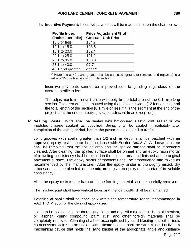
PORTLAND CEMENT CONCRETE PAVEMENT 380
Page 217
h. Incentive Payment: Incentive payments will be made based on the chart below:
Profile Index (inches per mile)
Price Adjustment % of Contract Unit Price
10.0 or less 104.7 10.1 to 15.0 103.5 15.1 to 20.0 102.4 20.1 to 25.0 101.2 25.1 to 35.0 100.0 35.1 to 40.0 97.7 40.1 and greater grind*1
*1 Pavement at 40.1 and greater shall be corrected (ground or removed and replaced) to a value of 35.0 or less in any 0.1 mile section.
Incentive payments cannot be improved due to grinding regardless of the average profile index.
The adjustments in the unit price will apply to the total area of the 0.1 mile-long section. The area will be computed using the total lane width (12 feet or less) and the total length of the section (0.1 mile or less if it is the segment at the end of the project or at the end of a paving section adjacent to an exception).
P. Sealing Joints: Joints shall be sealed with hot-poured elastic joint sealer or low
modulus silicone sealant as specified. Joints shall be sealed immediately after completion of the curing period, before the pavement is opened to traffic.
Joint grooves with spalls greater than 1/2 inch in depth shall be patched with an approved epoxy resin mortar in accordance with Section 390.2 C. All loose concrete shall be removed from the spalled area and the spalled surface shall be thoroughly cleaned. After cleaning, the spalled surface shall be primed and an epoxy resin mortar of troweling consistency shall be placed in the spalled area and finished as the original pavement surface. The epoxy binder components shall be proportioned and mixed as recommended by the manufacturer. After the epoxy binder is thoroughly mixed, dry silica sand shall be blended into the mixture to give an epoxy resin mortar of trowelable consistency. After the epoxy resin mortar has cured, the forming material shall be carefully removed. The finished joint shall have vertical faces and the joint width shall be maintained. Patching of spalls shall be done only within the temperature range recommended in AASHTO M 235, for the class of epoxy used. Joints to be sealed shall be thoroughly clean and dry. All materials such as old sealant, oil, asphalt, curing compound, paint, rust, and other foreign materials shall be completely removed. Cleaning shall be accomplished by sand blasting and other tools as necessary. Joints to be sealed with silicone sealant shall be sand blasted utilizing a mechanical device that holds the sand blaster at the appropriate angle and distance
380 PORTLAND CEMENT CONCRETE PAVEMENT
Page 218
from the joint to ensure proper cleaning. The device shall have a mechanism attached that will correctly guide the device in the joint.
Just prior to sealing, each joint shall be blown out using a jet of compressed air, at a working pressure of not less than 90 psi, to remove all traces of dust. Air compressors used for cleaning joints shall be equipped with traps capable of removing all free water and oil from the compressed air. Joint sealer application will not be permitted when the air or pavement temperature near the joint is less than 40°F or is 40°F and falling.
The sealant shall be applied without spilling on the exposed surface. Sealant on the surface of the concrete pavement shall be removed immediately and the pavement surface cleaned.
Failure of the joint material in either adhesion or cohesion will be cause for rejection. Repair shall be at the expense of the Contractor. Shoulder joints between Portland cement concrete pavement and asphalt concrete shoulders shall be sealed in accordance with Section 320.3 K.
1. Hot-Poured Elastic Joint Sealer: Hot-poured elastic joint sealer shall be stirred
during heating so that localized overheating does not occur. All joints shall be sealed with an approved pressure sealing device, equipped with a nozzle inserted into the joint, so sealing material will be forced from the bottom of the joint to the top.
2. Silicone Sealant: Silicone sealant shall be applied with a mechanical device
equipped with a nozzle or spout shaped to fit into the joint. The joint sealant shall be applied under pressure from the inside of the joint to remove entrapped air and ensure good joint contact.
Backer rod shall be installed to the proper depth to produce the width and depth of sealant specified. The sealant surface shall be tooled to produce a slightly concave surface below the pavement surface. Tooling shall be accomplished before a skin forms on the sealant surface. The use of water, soap, or oil as a tooling aid will not be permitted.
3. Seasonal Limitations: Silicone sealing operations will only be permitted between
May 1 and October 15, inclusive, unless the Contractor has received written permission from the Region Engineer to continue sealing later than October 15. Silicone sealing operations will only be permitted when the air and pavement surface temperatures are 40°F or greater and rising. Without approval from the Engineer to continue silicone sealing operations after the October 15 seasonal limitation, the Contractor shall only perform the initial cut at all joints. Beginning no sooner than May 1 of the following year the Contractor shall widen the joints, install the backer rod, and seal joint with silicone according to Section 380.3 P.
PORTLAND CEMENT CONCRETE PAVEMENT 380
Page 219
All costs related to the sealing seasonal limitations including additional labor, materials, equipment, traffic control, mobilization, and incidentals shall be at the expense of the Contractor.
Q. Application of Live Load: The pavement shall not be opened to traffic until the
concrete has attained a compressive strength of 4,000 psi. The pavement shall be cleaned prior to opening to traffic.
When concrete is placed adjoining a previously constructed pavement, the paving machines, mechanical spreaders, and other heavy equipment shall not be operated on the existing pavement until the existing concrete has attained a compressive strength of 3000 psi. Equipment operated on a previously constructed pavement that has attained a compressive strength of at least 3000 psi but less than 4000 psi shall be tracked type equipment. Hauling units shall not be allowed on the concrete until it has attained a compressive strength of 4000 psi. Working platforms and tining, curing, and other lightweight finishing equipment may be operated on the edge of the existing concrete 72 hours after the concrete was placed. With the approval of the Engineer, lightweight sealing equipment, including but not limited to, pickup and trailer, hot kettle, and air compressor may be operated on the slab more than 72 hours after the concrete was placed. When operating on previously constructed lanes, measures shall be taken to protect the previously constructed lane from becoming marred by the equipment.
R. Tolerance in Pavement Thickness: The pavement thickness will be determined by
average caliper measurement of cores tested in accordance with AASHTO T 148. Cores shall be sampled in accordance with AASHTO T 24.
Cores may be taken in areas believed to be deficient in thickness. Pavement deficiencies verified by these core measurements will be considered under the provisions of Section 5.3. These core measurements will not be used to determine pavement thickness as set forth in the following: For the purpose of establishing an adjusted unit price for pavement, units are to be considered separately. One random core location will be determined by the Engineer for each of the units as described in Table 1. Additional cores, if needed, within the unit will be sampled at the interval for additional cores in Table 1. The sizes of units taken from Table 1 are determined as follows. (For concrete shoulders, see paragraph 9 below.) 1. Width: The width of the pavement represented shall be the pavement surface
between adjacent longitudinal construction joints; between a longitudinal construction joint and the pavement edge; or between two pavement edges where the entire width is poured in one operation.
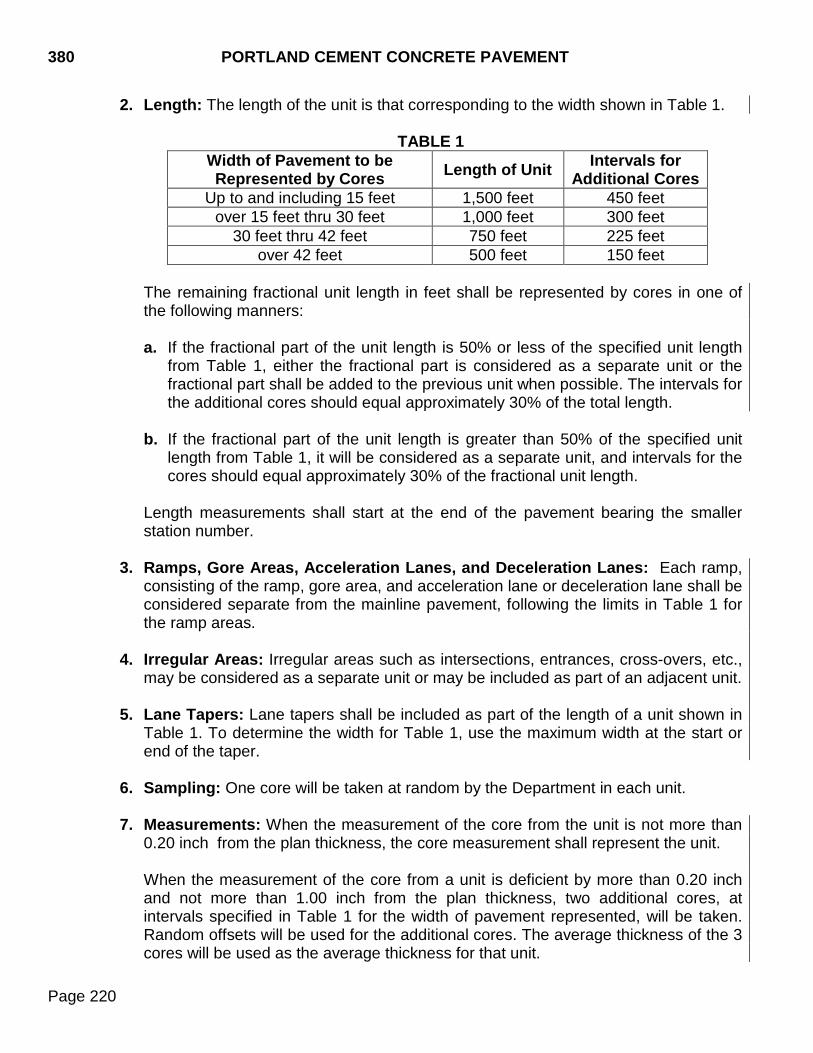
380 PORTLAND CEMENT CONCRETE PAVEMENT
Page 220
2. Length: The length of the unit is that corresponding to the width shown in Table 1.
TABLE 1 Width of Pavement to be Represented by Cores Length of Unit Intervals for
Additional Cores Up to and including 15 feet 1,500 feet 450 feet
over 15 feet thru 30 feet 1,000 feet 300 feet 30 feet thru 42 feet 750 feet 225 feet
over 42 feet 500 feet 150 feet The remaining fractional unit length in feet shall be represented by cores in one of the following manners: a. If the fractional part of the unit length is 50% or less of the specified unit length
from Table 1, either the fractional part is considered as a separate unit or the fractional part shall be added to the previous unit when possible. The intervals for the additional cores should equal approximately 30% of the total length.
b. If the fractional part of the unit length is greater than 50% of the specified unit
length from Table 1, it will be considered as a separate unit, and intervals for the cores should equal approximately 30% of the fractional unit length.
Length measurements shall start at the end of the pavement bearing the smaller station number.
3. Ramps, Gore Areas, Acceleration Lanes, and Deceleration Lanes: Each ramp, consisting of the ramp, gore area, and acceleration lane or deceleration lane shall be considered separate from the mainline pavement, following the limits in Table 1 for the ramp areas.
4. Irregular Areas: Irregular areas such as intersections, entrances, cross-overs, etc.,
may be considered as a separate unit or may be included as part of an adjacent unit.
5. Lane Tapers: Lane tapers shall be included as part of the length of a unit shown in Table 1. To determine the width for Table 1, use the maximum width at the start or end of the taper.
6. Sampling: One core will be taken at random by the Department in each unit.
7. Measurements: When the measurement of the core from the unit is not more than
0.20 inch from the plan thickness, the core measurement shall represent the unit.
When the measurement of the core from a unit is deficient by more than 0.20 inch and not more than 1.00 inch from the plan thickness, two additional cores, at intervals specified in Table 1 for the width of pavement represented, will be taken. Random offsets will be used for the additional cores. The average thickness of the 3 cores will be used as the average thickness for that unit.
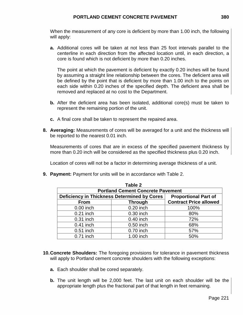
PORTLAND CEMENT CONCRETE PAVEMENT 380
Page 221
When the measurement of any core is deficient by more than 1.00 inch, the following will apply:
a. Additional cores will be taken at not less than 25 foot intervals parallel to the
centerline in each direction from the affected location until, in each direction, a core is found which is not deficient by more than 0.20 inches. The point at which the pavement is deficient by exactly 0.20 inches will be found by assuming a straight line relationship between the cores. The deficient area will be defined by the point that is deficient by more than 1.00 inch to the points on each side within 0.20 inches of the specified depth. The deficient area shall be removed and replaced at no cost to the Department.
b. After the deficient area has been isolated, additional core(s) must be taken to
represent the remaining portion of the unit. c. A final core shall be taken to represent the repaired area.
8. Averaging: Measurements of cores will be averaged for a unit and the thickness will be reported to the nearest 0.01 inch.
Measurements of cores that are in excess of the specified pavement thickness by more than 0.20 inch will be considered as the specified thickness plus 0.20 inch.
Location of cores will not be a factor in determining average thickness of a unit.
9. Payment: Payment for units will be in accordance with Table 2.
Table 2
Portland Cement Concrete Pavement Deficiency in Thickness Determined by Cores Proportional Part of
Contract Price allowed From Through 0.00 inch 0.20 inch 100% 0.21 inch 0.30 inch 80% 0.31 inch 0.40 inch 72% 0.41 inch 0.50 inch 68% 0.51 inch 0.70 inch 57% 0.71 inch 1.00 inch 50%
10. Concrete Shoulders: The foregoing provisions for tolerance in pavement thickness
will apply to Portland cement concrete shoulders with the following exceptions:
a. Each shoulder shall be cored separately.
b. The unit length will be 2,000 feet. The last unit on each shoulder will be the appropriate length plus the fractional part of that length in feet remaining.
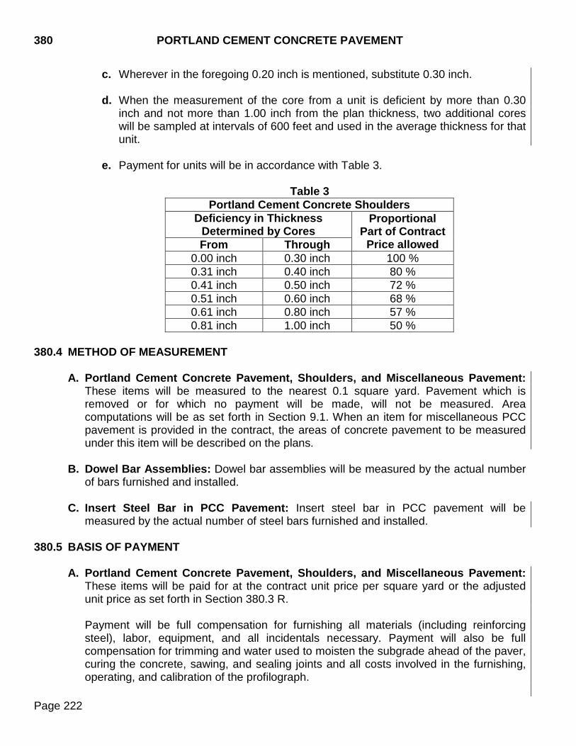
380 PORTLAND CEMENT CONCRETE PAVEMENT
Page 222
c. Wherever in the foregoing 0.20 inch is mentioned, substitute 0.30 inch.
d. When the measurement of the core from a unit is deficient by more than 0.30 inch and not more than 1.00 inch from the plan thickness, two additional cores will be sampled at intervals of 600 feet and used in the average thickness for that unit.
e. Payment for units will be in accordance with Table 3.
Table 3
Portland Cement Concrete Shoulders Deficiency in Thickness
Determined by Cores Proportional
Part of Contract Price allowed From Through
0.00 inch 0.30 inch 100 % 0.31 inch 0.40 inch 80 % 0.41 inch 0.50 inch 72 % 0.51 inch 0.60 inch 68 % 0.61 inch 0.80 inch 57 % 0.81 inch 1.00 inch 50 %
380.4 METHOD OF MEASUREMENT
A. Portland Cement Concrete Pavement, Shoulders, and Miscellaneous Pavement:
These items will be measured to the nearest 0.1 square yard. Pavement which is removed or for which no payment will be made, will not be measured. Area computations will be as set forth in Section 9.1. When an item for miscellaneous PCC pavement is provided in the contract, the areas of concrete pavement to be measured under this item will be described on the plans.
B. Dowel Bar Assemblies: Dowel bar assemblies will be measured by the actual number
of bars furnished and installed. C. Insert Steel Bar in PCC Pavement: Insert steel bar in PCC pavement will be
measured by the actual number of steel bars furnished and installed. 380.5 BASIS OF PAYMENT
A. Portland Cement Concrete Pavement, Shoulders, and Miscellaneous Pavement: These items will be paid for at the contract unit price per square yard or the adjusted unit price as set forth in Section 380.3 R.
Payment will be full compensation for furnishing all materials (including reinforcing steel), labor, equipment, and all incidentals necessary. Payment will also be full compensation for trimming and water used to moisten the subgrade ahead of the paver, curing the concrete, sawing, and sealing joints and all costs involved in the furnishing, operating, and calibration of the profilograph.

PORTLAND CEMENT CONCRETE PAVEMENT 380
Page 223
The amount bid on these items shall be based on the specified amount of cement per cubic yard. If a cement factor is not shown on the plans, the amount bid shall be based on 600 pounds per cubic yard for pavement, shoulders and pavement-miscellaneous.
B. Dowel Bar Assemblies: Dowel bar assemblies will be paid for at the contract unit price
per each dowel bar. Payment will be full compensation for labor, materials, equipment, and all incidentals necessary to furnish and install the assemblies.
C. Insert Steel Bar in PCC Pavement: Insert steel bar in PCC pavement will be paid for
at the contract unit price per each steel bar. Payment will be full compensation for labor, materials, equipment, and all incidentals necessary to furnish and install the steel bar.

380 PORTLAND CEMENT CONCRETE PAVEMENT
Page 224
THIS PAGE INTENTIONALLY LEFT BLANK

CONCRETE SPALL REPAIR 390
Page 225
390.1 DESCRIPTION
This work consists of removal of sealant from transverse contraction joints, repair of spalled areas, sawing, cleaning, and resealing joints.
390.2 MATERIALS
A. Bonding Mortar for Concrete Patches:
1. Cement: Cement shall conform to Section 750.
2. Water: Water shall conform to Section 790.
3. Sand: Sand shall conform to Section 810.1.
4. Proportioning: Bonding mortar shall be mixed in the following proportions by volume:
2 parts Portland cement. 1 part sand. Mix with only enough water to form a thick creamy consistency.
B. Concrete Patch Material: Concrete patching material shall be one of the following and
approved by the Department’s Concrete Engineer:
1. Type I: A packaged, dry, rapid-hardening mortar conforming to the requirements of ASTM C 928, Type R-3 containing no chloride ions. A magnesium or phosphate based product will not be allowed. If extender aggregate is added, the extender aggregate shall conform to Section 820.
2. Type II: A packaged, dry, rapid-hardening concrete conforming to the requirements
of ASTM C 928, Type R-3 containing no chloride ions. A magnesium or phosphate base product will not be allowed. If extender aggregate is added, the extender aggregate shall conform to Section 820.
3. Type III: A dry, bagged air entrained concrete patching material (known as 3U18)
meeting the following requirements: a. Materials:
1) Cement: Cement shall conform to Section 750. 2) Coarse Aggregate: Coarse aggregate shall conform to Section 820 except
the gradation shall conform to the gradation specified in Section 390.2 B.3.b.
3) Fine Aggregate: Fine aggregate shall conform to Section 800 for Class M concrete except the gradation shall conform to the gradation specified in Section 390.2 B.3.b.
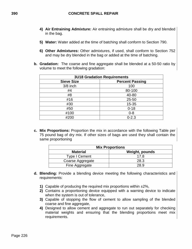
390 CONCRETE SPALL REPAIR
Page 226
4) Air Entraining Admixture: Air entraining admixture shall be dry and blended
in the bag. 5) Water: Water added at the time of batching shall conform to Section 790. 6) Other Admixtures: Other admixtures, if used, shall conform to Section 752
and may be dry blended in the bag or added at the time of batching.
b. Gradation: The coarse and fine aggregate shall be blended at a 50-50 ratio by volume to meet the following gradation:
3U18 Gradation Requirements
Sieve Size Percent Passing 3/8 inch 100
#4 80-100 #8 40-80
#16 25-50 #30 15-35 #50 0-18 #100 0-8 #200 0-2.3
c. Mix Proportions: Proportion the mix in accordance with the following Table per
75 pound bag of dry mix. If other sizes of bags are used they shall contain the same proportioning
Mix Proportions
Material Weight, pounds Type I Cement 17.8
Coarse Aggregate 28.3 Fine Aggregate 28.9
d. Blending: Provide a blending device meeting the following characteristics and
requirements:
1) Capable of producing the required mix proportions within ±2%, 2) Contains a proportioning device equipped with a warning device to indicate
when the system is out of tolerance, 3) Capable of stopping the flow of cement to allow sampling of the blended
coarse and fine aggregate, 4) Designed to allow cement and aggregate to run out separately for checking
material weights and ensuring that the blending proportions meet mix requirements.
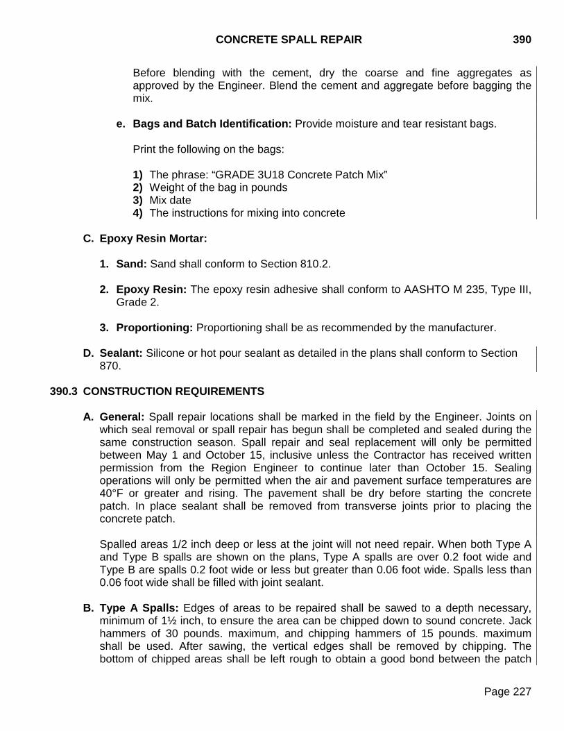
CONCRETE SPALL REPAIR 390
Page 227
Before blending with the cement, dry the coarse and fine aggregates as approved by the Engineer. Blend the cement and aggregate before bagging the mix.
e. Bags and Batch Identification: Provide moisture and tear resistant bags.
Print the following on the bags: 1) The phrase: “GRADE 3U18 Concrete Patch Mix” 2) Weight of the bag in pounds 3) Mix date 4) The instructions for mixing into concrete
C. Epoxy Resin Mortar:
1. Sand: Sand shall conform to Section 810.2.
2. Epoxy Resin: The epoxy resin adhesive shall conform to AASHTO M 235, Type III, Grade 2.
3. Proportioning: Proportioning shall be as recommended by the manufacturer.
D. Sealant: Silicone or hot pour sealant as detailed in the plans shall conform to Section
870.
390.3 CONSTRUCTION REQUIREMENTS A. General: Spall repair locations shall be marked in the field by the Engineer. Joints on
which seal removal or spall repair has begun shall be completed and sealed during the same construction season. Spall repair and seal replacement will only be permitted between May 1 and October 15, inclusive unless the Contractor has received written permission from the Region Engineer to continue later than October 15. Sealing operations will only be permitted when the air and pavement surface temperatures are 40°F or greater and rising. The pavement shall be dry before starting the concrete patch. In place sealant shall be removed from transverse joints prior to placing the concrete patch.
Spalled areas 1/2 inch deep or less at the joint will not need repair. When both Type A and Type B spalls are shown on the plans, Type A spalls are over 0.2 foot wide and Type B are spalls 0.2 foot wide or less but greater than 0.06 foot wide. Spalls less than 0.06 foot wide shall be filled with joint sealant.
B. Type A Spalls: Edges of areas to be repaired shall be sawed to a depth necessary,
minimum of 1½ inch, to ensure the area can be chipped down to sound concrete. Jack hammers of 30 pounds. maximum, and chipping hammers of 15 pounds. maximum shall be used. After sawing, the vertical edges shall be removed by chipping. The bottom of chipped areas shall be left rough to obtain a good bond between the patch
390 CONCRETE SPALL REPAIR
Page 228
and the old concrete. The area shall then be sandblasted, and the sand blown from the joint and the patch area.
Partially exposed dowel bars shall be coated or covered with an approved bond breaker. Improperly aligned or positioned bars shall be removed.
Prior to placing the patch, the joint shall be formed to a width equal to the current opening. The area shall be chipped to a uniform depth, to facilitate forming to the depth of removal. Forming material shall be foam core board or other stiff material capable of standing without deflection. The forming material shall be one unit for the length of the spall repair area. The concrete patch material shall be mixed and placed in accordance with the manufacturer’s technical data sheet. The Contractor shall provide a manufacturer’s technical data sheet to the Engineer prior to performing the work. At placement, the patch material shall be between 50°F and 90°F and shall be maintained above 45°F until 3,000 psi has been obtained. Traffic will not be permitted over the area until the repair material has reached 3,000 psi. Upon removal of the forming material, the joint shall be sawed, cleaned, and sealed. Specific installation details shall conform to the following based on the type of concrete patch material used: 1. Type I & II (packaged, dry, rapid hardening mortar or concrete – ASTM C928 Type
R-3) If a bonding agent or bonding mortar is recommended by the manufacturer’s technical data sheet, the bonding agent shall be in accordance with the manufacturer’s guidelines. The patch shall be screeded from existing pavement to existing pavement. The top surface shall be trowel finished from middle of patch to existing concrete. Any saw cuts that extend beyond the patch perimeter shall be filled with patching material. The surfaces of the patch shall be given a broomed finish. Patched areas shall be wet cured with curing blankets and white polyethylene sheeting for a minimum of 8 hours then sprayed with curing compound at a minimum rate of 1 gallon per 150 square feet.
2. Type III (bagged air entrained concrete patching material - 3U18)
A layer of bonding mortar shall be scrubbed into and over the surfaces to be patched immediately prior to patch placement. Excess grout must not pool in the low areas.
CONCRETE SPALL REPAIR 390
Page 229
The patch shall be placed before the bonding mortar dries and shall be consolidated by vibration. The patch shall be screeded from existing pavement to existing pavement. The top surface shall be trowel finished from middle of patch to existing concrete. After screeding and finishing, the same bonding grout shall be used to paint the edges of the repair. Any saw cuts that extend beyond the patch perimeter shall be filled with patching material and must also have the surface painted with bonding grout. The surfaces of the patch shall be given a broomed finish. The patched area shall be sprayed with curing compound at a minimum rate of 1 gallon per 150 square feet. An additional coat of curing compound shall be applied after 20 minutes but less than 1 hour after the first application.
C. Type B Spalls: The spalled concrete shall be removed and the areas chipped down to
sound concrete. The resulting areas shall be left rough to obtain a good bond between patch and concrete. The area shall then be sandblasted and the joint formed as specified for Type A spalls. The entire area shall be given a coat of straight epoxy resin (without aggregates). Epoxy resin mortar shall immediately be tamped in place and troweled off. Placement of epoxy will be permitted only within the temperature range recommended in AASHTO M 235, for the class of epoxy used. Form removal, joint sawing, and traffic over the patch area will not be permitted for 8 hours after placement.
D. Saw and Seal Joints: Transverse joints shall be sawed to the uniform width and depth
specified. For silicone sealant, the Contractor shall have backer rod available for variable width joints up to 1½ inches wide. Prior to sealing, the joints shall be cleaned in conformance with Section 380. Once cleaning operations begin, traffic will not be permitted over repair areas until joints are sealed and seal material has cured.
390.4 METHOD OF MEASUREMENT
A. Saw and Seal Joints: Saw and seal joints will be measured to the nearest foot. The areas that have spall repairs will not be measured.
B. Repair of Type A Spalls: Repair of Type A spalls will be measured to the nearest 0.1
square foot. Surface measurements will be taken to the nearest 0.1 foot.
C. Repair of Type B Spalls: Repair of Type B spalls will be measured to the nearest 0.1 foot or to the nearest 0.1 square foot, as shown on the plans.
390.5 BASIS OF PAYMENT
A. Saw and Seal Joints: Saw and seal joints will be paid for at the contract unit price per foot. Payment will be full compensation for removal of old sealant, cleaning, and resealing the joints.
390 CONCRETE SPALL REPAIR
Page 230
B. Repair of Type A Spalls: Repair of Type A spalls will be paid for at the contract unit
price per square foot. Payment will be full compensation for sawing, sealing, materials, labor, equipment, and incidentals required.
C. Repair of Type B Spalls: Repair of Type B spalls will be paid for at the contract unit
price per foot or to the nearest square foot, as shown on the plans. Payment will be full compensation for sawing, sealing, materials, labor, equipment, and all incidentals required.
UNDERSEALING 391
Page 231
391.1 DESCRIPTION
This work consists of filling existing voids under PCC pavement by drilling injection holes and pumping a cement/fly ash grout under the pavement slab.
391.2 MATERIALS
A. Design Mix: The design mix for grout shall conform to the following proportions by absolute volume:
1 Part Portland cement 3 Parts fly ash Water to achieve the specified fluidity
Fluidity of the grout when measured by a flow cone in accordance with ASTM C939 shall have a time of efflux between 9 and 15 seconds.
The Contractor shall submit for approval materials proposed for use. The submittal shall include mill certification for cement, physical and chemical analysis for fly ash, and tests of the grout slurry by a Department approved testing laboratory. Tests shall show one, three, and seven day strengths, flow cone times, shrinkage and expansion observed, and time of initial set. The seven day strength shall be at least 600 psi as measured in accordance with ASTM C942. As an alternate, standard 6 inch diameter by 12 inch high water tight concrete cylinder molds may be used to determine seven day strength. When the cylinder molds are used, the strength shall be 700 psi minimum. Alternate design mixes for the grout may be submitted to the Engineer for approval.
B. Portland Cement: Type I or Type II cement is required. The cement shall meet the
requirements of Section 750.
C. Fly Ash: Fly ash shall conform to Section 753.
D. Water: Water shall conform to Section 790. 391.3 CONSTRUCTION REQUIREMENTS
A. General: The Contractor, or subcontractor performing the undersealing, shall have prior experience with undersealing operations and shall have personnel on the project with expertise in undersealing. Prior to awarding the contract, the Department may require the Contractor to substantiate previous experience with this type of work. The Contractor, upon Department request, shall be required to submit a list of at least three projects on which the Contractor or undersealing subcontractor has satisfactorily completed similar work. Deflection testing of the joints shall be performed as required by the Engineer. Testing may be performed either before and or after the undersealing operation.
391 UNDERSEALING
Page 232
The Contractor shall take the necessary precautions to avoid slurry or foam from entering areas such as pipes, culverts, voids behind abutments, and other such areas that may hinder the functionality of the roadway. If foam or slurry enters these areas, it shall be removed to the satisfaction of the Engineer at no additional expense to the Department. Jacking foam shall not be used for undersealing except as allowed as per Section 392.3 A.
B. Deflection Testing: The Contractor shall furnish either a deflection measuring device that can apply at least 8000 pounds of force (either vibrating or falling weight), or a loaded vehicle having a single axle that can be loaded to 18 kips evenly distributed between the two sides to test joints and cracks.
1. If a deflection measuring device is used, the loading plate shall be placed as close
as possible to the slab corner. Load transfer shall be measured with sensors that are placed adjacent to the joint or crack on the loaded and unloaded side.
2. If a loaded vehicle is used as a measuring device, a gauge mount shall be
positioned with one gauge referenced to the corner of each slab on both sides of the joint near the shoulder edge perpendicular to the pavement joint. The gauges should then be zeroed with no load on the slab on either side of the joint. A loaded truck shall then be moved into position with the center of the 18 kip axle 1 foot behind the joint and the outside test wheel 1 foot from the pavement edge, both gauges shall be read.
The loaded truck shall be moved across the joint to a position 1 foot past the joint and both gauges read again. Deflection testing shall be performed when the slabs are not experiencing curl or joint closure. This normally takes place between midnight and 10:00 a.m. The Engineer may stop testing earlier if there is evidence of slab lockup due to thermal expansion of the slabs. The Engineer may allow the testing to continue after the hour specified, providing the slabs are not interlocked or under compression.
Upon completion of preliminary deflection testing of joints, the Engineer will determine the deflection range that warrants undersealing.
C. Weather and Seasonal Limitations: Grout undersealing shall not be performed when
the pavement surface temperature is below 40°F, or if the subgrade or base course is frozen.
D. Equipment:
1. Grout Plant: The grout plant shall consist of a positive displacement cement
injection pump and a high speed colloidal mixing machine. The colloidal mixing machine shall operate between 800 and 2000 RPM, creating a high shearing action and subsequent pressure release to make a homogeneous mixture
UNDERSEALING 391
Page 233
The injection pump shall have pressure capability from 250 to 300 psi when pumping a grout slurry mixed to a 12 second flow cone time. The pump shall be capable of continuous pumping at rates as low as 1.5 gallons per minute or have the system modified by adding a recirculation hose and valve at the discharge of the pump.
2. Drilling: An air compressor and rock drills or other devices capable of drilling the
injection holes through the pavement shall be required. The equipment shall be operated in such a manner that holes are vertical and not out of round. Holes shall be drilled in a manner that prevents breakout at the bottom of the pavement. The downward force of the drill shall not exceed 200 pounds.
E. Drilling Holes: A hole pattern for grout injection will be determined by the Engineer in
consultation with the Contractor. Variations from plans quantity will not be considered cause for renegotiation of the contract unit prices.
Holes shall be between 1.5 and 2 inches in diameter drilled vertically and round to a depth sufficient to penetrate any stabilized base and into the subgrade material. Subgrade penetration shall not exceed 3 inches. Holes may be washed to create a small cavity, allowing initial spread of grout.
F. Subsealing: During subsealing operations, the upward movement of the pavement
shall not exceed 0.125 inches, unless otherwise allowed by the Engineer. The Contractor shall supply equipment to measure slab deflection and lift. This equipment shall be capable of detecting simultaneously the movement of the pavement edge or any two outside slab corners adjacent to a joint and the adjoining shoulder. The equipment shall have the capacity of accurately measuring to 0.001 inches. Measurement devices to detect slab movement with respect to a stable reference point shall be subject to approval before use. Pavement that has been raised in excess of this amount may be subject to removal and replacement, or grinding to the correct grade, as determined by the Engineer.
An expanding rubber packer or other approved device connected to the discharge from the plant shall be lowered into the hole. The discharge end of the packer or hose shall not extend below the lower surface of the concrete pavement.
Each hole shall be pumped until maximum pressure is built up or material is observed flowing from hole to hole. Maximum pressure shall be 60 psi. A short surge up to 150 psi will be allowed when starting to pump the hole. The pressure shall be monitored by a gauge in the grout line that is protected from the grout slurry. Mixed material shall not be held in the mixer or injection sump pump for more than one hour after mixing. Any material held longer than one hour shall be wasted and will not be paid for. Additional water shall not be added after initial mixing of the grout.
Water displaced from the void structure by the grout shall be allowed to flow out freely. Excessive loss of the grout through cracks, joints, other drilled holes, or from back pressure in the hose or in the shoulder area will not be tolerated and will not be paid for.
391 UNDERSEALING
Page 234
If the Engineer determines that continued grout injection at a specific location is no longer feasible due to major voids the Engineer may direct the Contractor to cease grout injection at that location. Upon completion of undersealing and prior to the injection grout drying on the sides of the drill holes, the drill holes shall be filled with a fast setting sand/cement mixture or other patch material approved by the Engineer. If the injection grout has dried on the sides of the drill holes, the sides of the drill holes shall be sand blasted and blown out prior to filling the holes with fast setting sand/cement mixture.
G. Radial Cracks: Cracks emanating radially from the grout injection holes will be
presumed to have been caused by improper injection techniques by the Contractor. For each 5 linear feet of crack measured, the pay quantity will be reduced by 1 cubic foot of grout. As an alternative, the Engineer may require replacement of the damaged panel or a portion of the damaged panel, at the Contractor's expense.
H. Transverse Cracks: If cracks develop between adjacent grout injection holes, the
Contractor shall repair the cracks by a satisfactory method approved by the Engineer. As an alternative, the Engineer may require replacement of the entire panel or a portion of a damaged panel at the Contractor's expense.
391.4 METHOD OF MEASUREMENT
A. PCC Drill Holes: The holes accepted will be measured per each. The holes drilled after the deflection testing will not be included for payment.
B. PCC Pavement Undersealing: Pavement undersealing will be measured to the
nearest cubic foot. Portland cement will be the only material measured for payment. One bag of cement (94 pounds) of PCC pavement undersealing (3½ bags of cement shall of PCC pavement undersealing).
C. Deflection Testing: The test locations will be measured per each. Testing before and
after undersealing at the same joint will be measured as separate locations.
If the deflection testing after undersealing is in excess of 0.010 inches further undersealing will be required. Should the testing, after the undersealing is performed, indicate a need for further undersealing at that joint, all additional testing at that joint will be at no additional cost to the Department.
391.5 BASIS OF PAYMENT
A. PCC Drill Holes: The holes drilled will be paid for at the contract unit price per each. Payment will be full compensation for all materials, equipment, tools, and incidentals required to drill, plug, and seal the holes after the undersealing is completed.

UNDERSEALING 391
Page 235
B. PCC Pavement Undersealing: Pavement undersealing will be paid for at the contract unit price per cubic foot. Payment will be full compensation for all materials, including fly ash and water, labor, equipment, tools, and incidentals required.
C. Deflection Testing: Testing will be paid for at the contract unit price per each test
location. Payment will be full compensation for all materials, equipment, tools, and incidentals required.

391 UNDERSEALING
Page 236
THIS PAGE INTENTIONALLY LEFT BLANK
PAVEMENT JACKING 392
Page 237
392.1 DESCRIPTION
This work consists of hydraulic pressure jacking PCC pavement to correct the pavement profile. Jacking is accomplished by drilling injection holes and pumping a cement/fly ash slurry or liquid polyurethane (foam) under the slab.
392.2 MATERIALS
A. Jacking Slurry Design Mix: The design mix for grout shall conform to the following proportions by absolute volume:
1 Part Portland cement 3 Parts fly ash Water to achieve the specified fluidity
Fluidity of the grout when measured by a flow cone in accordance with ASTM C939 shall have a time of efflux between 16 and 36 seconds. During initial injection at each hole an efflux time between 9 and 15 seconds will be permitted. The use of material with an efflux time between 9 and 15 seconds shall be discontinued prior to movement of the pavement. The Contractor shall be required to perform this test prior to placing any material.
The Contractor shall submit for approval, materials proposed for use. The submittal shall include mill certification for cement, physical and chemical analysis for fly ash, and tests of the grout slurry by a Department approved testing laboratory. Tests shall show one, three, and seven day strengths, flow cone times, shrinkage, and expansion observed, and time of initial set. The seven day strength shall be at least 600 psi as measured in accordance with ASTM C942. As an alternate, standard 6 inch diameter by 12 inch high water tight concrete cylinder molds may be used to determine seven day strength. When the cylinder molds are used, the strength shall be 700 psi. minimum. Alternate jacking slurry design mixes may be submitted to the Engineer for approval.
B. Portland Cement: Type I or Type II cement is required. The cement shall meet the requirements of Section 750.
C. Fly Ash: Fly ash shall conform to Section 753.
D. Water: Water shall conform to Section 790.
E. Jacking Foam: Water blown formulation of high-density polyurethane. The high
density, closed cell polyurethane shall be hydrophobic and shall exhibit the following physical characteristics and properties: The polyurethane foam shall be designed for pavement jacking, have a free rise density of 3.0 to 4.2 pounds per cubic foot in accordance with ASTM D1622, and shall have a minimum compressive strength of 40 psi in accordance with ASTM D1621. The material shall be resistant to oils, gasoline, and most solvents.
392 PAVEMENT JACKING
Page 238
392.3 CONSTRUCTION REQUIREMENTS
A. General: The Contractor, or subcontractor performing the pavement jacking, shall have
prior experience with pavement jacking operations and shall have personnel on the project with expertise in determining injection hole patterns and jacking sequences. Prior to awarding the contract, the Department may require the Contractor to substantiate previous experience with this type of work. The Contractor, upon Department request, shall be required to submit a list of at least three projects on which the Contractor or the pavement jacking subcontractor have satisfactorily completed similar work.
The Contractor shall not start any new location unless the new location can be completed in the same day. If any location is started and cannot be completed prior to the end of the day’s work, the entire area, including adjacent lanes, shall be undersealed in accordance with Section 391 before stopping for the day. If PCC pavement foam jacking is specified, foam may be used to underseal adjacent areas. The Contractor shall take the necessary precautions to avoid slurry or foam from entering areas such as pipes, culverts, voids behind abutments, and other such areas that may hinder the functionality of the roadway. If foam or slurry enters these areas, it shall be removed to the satisfaction of the Engineer at no additional expense to the Department.
B. Weather and Seasonal Limitations: Pavement jacking shall not be performed when the pavement surface temperatures are below 40°F, or if the subgrade or base course is frozen. Pavement jacking shall not be performed when the subgrade contains an abnormal amount of moisture from recent rainfall, as evidenced by standing water on the pavement or in the joints or cracks.
C. Equipment:
1. Grout Plant: When jacking slurry is specified, the grout plant shall consist of a
positive displacement cement injection pump and a high speed colloidal mixing machine. The colloidal mixing machine shall operate between 800 and 2000 RPM, creating a high shearing action and subsequent pressure release to make a homogeneous mixture.
2. Drilling: An air compressor and rock drills or other devices capable of drilling the
injection holes through the pavement shall be required.
3. Pumping Unit: When Jacking Foam is specified, the Contractor shall furnish a truck-mounted pumping unit capable of injecting the high-density polyurethane formulation between the concrete pavement and the subbase and capable of controlling the rate of rise of the pavement. The pumping unit shall be equipped with a metering device to measure the quantity of material pumped.
PAVEMENT JACKING 392
Page 239
4. Laser Leveling Unit: The Contractor shall furnish a laser leveling unit to ensure that the concrete is raised to an even plane and to the required elevation.
D. Drilling Holes:
When jacking slurry is specified, a hole pattern for grout injection will be determined by the Engineer in consultation with the Contractor. The Engineer may delete any location or add new locations of pavement to be raised. Holes shall be between 1.5 and 2 inches in diameter, drilled vertically and round, to a depth sufficient to penetrate any stabilized base and into the subgrade material. Holes may be washed to create a small cavity, allowing initial spread of grout. Holes shall be drilled in a manner that prevents breakout at the bottom of the pavement. The downward force of the drill shall not exceed 200 pounds. Variations from plans quantity will not be considered cause for renegotiations of the contract unit prices. When jacking foam is specified, a hole pattern for injection will be determined by the Contractor in consultation with the Engineer. The Engineer may delete any location or add new locations of pavement to be raised. Holes shall be between 3/8 inch and 5/8 inch in diameter, drilled vertically and round to a depth sufficient to penetrate any stabilized base and in the subgrade material. Holes shall be drilled in a manner that prevents breakout at the bottom of the pavement.
E. Slurry Pavement Jacking: String lines shall be established and blocked up from the
pavement high points to monitor movement.
An expanding rubber packer or other approved device connected to the discharge from the plant shall be lowered into the hole. The discharge end of the packer or hose shall not extend below the lower surface of the concrete pavement. The Contractor shall pump in a pattern and in the amount required to raise the pavement to within 0.02 foot of the specified grade. Grade tolerances are applicable to both transverse and longitudinal grades. After the pavement has been raised to the desired elevation, all holes shall be injected to ensure complete filling of voids.
Continuous pressures up to 200 psi will be permitted. Pressures up to 300 psi will be allowed only for short periods. If the pavement is bonded to the subbase, brief pressure rises (10 seconds or less) up to 600 psi will be allowed. Mixed material shall not be held in the mixer or injection sump pump for more than one hour after mixing. Any material held longer than one hour shall be wasted and will not be paid for. Additional water shall not be added after initial mixing of the grout. Excessive loss of the slurry through cracks, joints, other drilled holes, or from back pressure in the hose or in the shoulder area will not be tolerated and will not be paid for. If the Engineer determines that continued slurry injection at a specific location is no longer feasible due to major voids the Engineer may direct the Contractor to cease slurry injection at that location.
392 PAVEMENT JACKING
Page 240
Upon completion of jacking and prior to the injection slurry drying on the sides of the drill holes, the drill holes shall be filled with a fast setting sand/cement mixture or other patch material approved by the Engineer. If the injection slurry has dried on the sides of the drill holes, the sides of the drill holes shall be sand blasted and blown out prior to filling the holes with fast setting sand/cement mixture.
F. Foam Pavement Jacking: The high-density polyurethane formulation is to be injected under the slab. The amount of rise shall be controlled using the pumping unit and by regulating the rate of injection.
The Contractor shall inject in a pattern and in the amount required to raise the pavement to within 0.02 foot of the specified grade. Grade tolerances are applicable to both transverse and longitudinal grades. A tight string line or laser level shall be used to monitor and verify elevations. After the pavement has been raised to the desired elevation, all holes shall be injected to ensure complete filling of voids. Excessive loss through cracks, joints, other drilled holes, from back pressure in the hose, in the shoulder area, or as a result of cleaning lines will not be paid for. The Contractor shall provide a scale for weighing the waste material. If the Engineer determines continued foam injection at a specific location is no longer feasible due to major voids, the Engineer may direct the Contractor to cease foam injection at the location. Upon completion of the jacking, the upper 2 inches of the drilled holes shall be filled with a fast setting sand/cement mixture or other patch material approved by the Engineer. The foam material shall be removed from the injection hole appropriately to ensure a good bond between the fast setting sand/cement mixture and the in place concrete.
G. Radial Cracks: The slab shall not be raised more than 1/4 inch while pumping in any one hole at any one time. Cracks emanating radially from the injection holes will be presumed to have been caused by improper injection techniques by the Contractor. For each 5 feet of crack measured, the pay quantity will be reduced by 1 cubic foot of grout or 10 pounds of polyurethane foam material.
H. Transverse Cracks: If cracks develop between adjacent injection holes, the Contractor shall repair the cracks by a satisfactory method approved by the Engineer.
I. Pavement Raised above Tolerances: Pavement raised above specified tolerances
shall be brought to grade by grinding. If over jacking is greater than 0.10 foot, satisfactory removal and replacement shall be required, at no cost to the Department.
392.4 METHOD OF MEASUREMENT
PCC pavement jacking slurry will be measured to the nearest cubic foot. Portland cement will be the only material measured for payment. One bag of cement (94 pounds) shall equal 1 cubic foot of PCC pavement jacking slurry.
PAVEMENT JACKING 392
Page 241
PCC pavement jacking foam will be measured to the nearest pound.
392.5 BASIS OF PAYMENT
PCC pavement jacking slurry will be paid for at the contract unit price per cubic foot. Payment will be full compensation for all materials, including fly ash, water, labor, equipment, tools, and incidentals required. PCC pavement jacking foam will be paid for at the contract unit price per pound. Payment will be full compensation for all materials, including high-density polyurethane foam, labor, equipment, tools, and incidentals required.

392 PAVEMENT JACKING
Page 242
THIS PAGE INTENTIONALLY LEFT BLANK
CRACKING AND SEATING OF PCC PAVEMENT 393
Page 243
393.1 DESCRIPTION
The work consists of cracking and seating concrete pavement prior to placing an asphalt concrete leveling course.
393.2 MATERIALS (Not Specified) 393.3 CONSTRUCTION REQUIREMENTS
A. General: Cracking and seating shall proceed continuously, during normal work hours, until the set of lanes under construction is completed. The pavement shall be seated on the same working day that it is cracked. The asphalt concrete leveling course shall be placed within 72 hours after the pavement has been cracked and seated. PCC pavement crossovers shall be cracked with the same pattern used for the driving lanes.
Work shall be performed during daylight hours. Prior to cracking the concrete pavement, existing asphalt concrete overlays shall be removed.
B. Equipment:
1. Pavement Breaker: Pavement cracking shall be accomplished with a spade or guillotine type breaker mounted on a vehicle capable of controlled forward and transverse movement. The breaker shall be capable of fracturing the pavement to the full depth, while maintaining the fractured face interlock of the aggregate.
2. Roller: A pneumatic roller with a minimum loaded weight of 35 ton shall be used to
seat the cracked pavement.
C. Cracking Locations: Pavement cracking shall be performed transverse to centerline at 2 foot intervals ± 6 inches. Breakers shall not be operated closer than 2 feet from an existing transverse joint. Cracking shall be full pavement depth without loss of interlock.
D. Test Section: Before routine cracking operations commence, the Contractor shall
demonstrate on a 200 foot test section on the project that the cracking and seating procedure is satisfactory to the Engineer. When inspecting the cores for cracking, it may be necessary to wet the core to verify cracking. The Contractor shall core or saw samples of sufficient size to establish adequacy of cracking. A minimum of four samples will be required in the test section and one sample per lane mile for routine operations. If subsequent samples indicate that the established cracking procedure is not producing acceptable results, additional test sections may be required to re-establish an acceptable cracking and seating procedure.
393 CRACKING AND SEATING OF PCC PAVEMENT
Page 244
E. Seating: The cracked pavement shall be seated by a minimum of two passes with the pneumatic roller. If two roller passes have not provided a firm seating of the cracked pavement, the rolling shall continue until the Engineer determines that the seating is adequate or pavement removal is required.
F. Cleaning: The cracked and seated pavement shall be cleaned of dirt, spalls, and loose
material by power brooming prior to tack coating. The cracked surface shall be cleaned of loose material at the end of each working day.
393.4 METHOD OF MEASUREMENT
A. Cracking and Seating PCC Pavement: Cracking and seating PCC pavement will be measured to the nearest 0.1 square yard.
B. Cored or Sawed Sample: Cored or sawed sample will be measured per each.
393.5 BASIS OF PAYMENT
A. Cracking and Seating PCC Pavement: Cracking and seating PCC pavement will be paid for at the contract unit price per square yard and shall be inclusive of cracking, seating, test strips, surface cleaning, and all tools, equipment, and labor necessary to perform the work.
B. Cored or Sawed Sample: Cored or sawed sample will be paid for at the contract unit
price per each and will include all tools, equipment, and labor necessary to perform the work. If additional cores or sawed samples are required because previous samples indicated unacceptable results, the additional cores will be at the Contractor’s expense.
RUBBLIZE PCC PAVEMENT (New Section) 394
Page 245
394.1 DESCRIPTION
This work consists of rubblizing the existing concrete pavement in preparation for an overlay.
394.2 MATERIALS (Not Specified) 394.3 CONSTRUCTION REQUIREMENTS
A. General: Rubblization of the concrete pavement shall be accomplished across the width and full depth of the pavement. The rubblization shall be done in partial widths when necessary to maintain traffic. The breaker shall be operated to avoid damaging the base and underlying structures including, but not limited to; pipe, box culverts, edge drains, and utilities. If damage occurs to the base or underlying structures, the Contractor shall repair any damage at no additional expense to the Department. The Contractor shall minimize the dispersion of dust from the rubblizing operation, until the rubblized surface is overlaid, by the application of water or other approved method.
Work shall be performed during daylight hours.
B. Equipment:
1. Requirements for all breakers: Rubblize the existing PCC pavement using either a self-contained, self-propelled multi-head pavement breaker; or a self-contained, self-propelled resonant frequency pavement breaker. Whip hammers, pile-driving hammers, crane and wrecking ball operations, and other equipment using up guided free-falling weights are not acceptable. The equipment used shall deliver such energy as necessary to provide a crack, which is distinguishable to the naked eye from a standing position without the use of water or other materials. The breaker shall be equipped with a screen to ensure debris will not enter the adjacent lane during the fracturing process, if traffic is maintained.
2. Multi Head Breaker: Breaking of the concrete pavement shall be accomplished
with a self-contained, self-propelled, unit with hammers mounted laterally in pairs with half the hammers in a forward row and the remainder diagonally offset in a rear row so that there is continuous breakage from side to side. The multi-head breaker must be capable of rubblizing a full lane width in a single pass to the degree specified in Section 394.3 C.
3. Resonant Breaker: Breaking the concrete pavement shall be accomplished with a
self-contained, self-propelled, resonant frequency-breaking unit capable of producing low amplitude 2000 pound force blows at a nominal frequency of not less than 44 cycles per second. The rubblizing operation shall proceed in a longitudinal direction, beginning at a shoulder or previously broken edge and progress toward the opposite shoulder or longitudinal centerline of the roadway. The resonant
394 RUBBLIZE PCC PAVEMENT (New Section)
Page 246
breaker must be capable of rubblizing the full width of the pavement in multiple passes to the degree specified in Section 394.3 C.
4. Rollers: A steel vibratory roller fitted with a “Z” pattern grid on the drum face having a gross weight (mass) of at least 10 tons, operated in vibratory mode. A smooth drum steel vibratory roller having a gross weight (mass) of at least 10 tons, operated in vibratory mode. A pneumatic roller having a gross weight (mass) of at least 10 tons.
C. Rubblization: Prior to rubblization, a joint shall be cut full depth at an existing joint on ramps or mainline where rubblization abuts concrete pavement which is to remain in place. In areas where the roadway must be covered one lane at a time, initial rubblization will extend a minimum of 6 inches beyond the width of the pavement to be covered. The Contractor shall break the concrete pavement uniformly across the pavement width into particles that have a maximum dimension less than or equal to 12 inches. In addition, 75% of the particles, as the Engineer determines visually, must have a maximum dimension less than or equal to the following:
In the bottom half of the slab; 9 inches In the top half of the slab; 3 inches At the surface of the slab; 2 inches
The Engineer may direct or allow larger maximum particle dimensions. Prior to the acceptance of the rubblizing procedure to be used, the Contractor shall rubblize and roll a 300 foot test strip, in one lane, for evaluation as designated by the Engineer. Break the test strip using sufficient energy and an operating speed such that the existing pavement is rubblized, full-depth, to the degree specified above. A 4 foot by 4 foot test hole shall be excavated from the edge to the middle of the lane at a location selected by the Engineer to determine if the breaker is producing pieces of the specified sizes. The material from the test hole shall be removed from the project and the hole shall be filled using base course or base course, salvage. For the remainder of the project, the Contractor shall excavate the equivalent of one test hole per lane mile, unless waived by the Engineer. If necessary to achieve the above rubblization size requirements, in areas where the concrete pavement is not able to deflect, the Engineer and Contractor may mutually agree to pre-crack the concrete pavement with a device meeting the requirements of Section 393.3 B.1. Reinforcement in the rubblized pavement, if any, shall be left in place. However, if any reinforcement is exposed at the surface from rubblizing or compaction, it shall be cut off

RUBBLIZE PCC PAVEMENT (New Section) 394
Page 247
2 inches below the surface and removed. Any loose joint filler, expansion material, or other similar items shall be removed.
D. Seating: Seat the rubblized pavement using vibratory steel wheel and pneumatic tired rollers. The two types of breakers are listed below with the corresponding sequence required for each.
1. Multi Head Breaker:
2 coverages with a steel vibratory roller fitted with a “Z” pattern grid on the roller face. 1 coverage with a pneumatic roller. 1 coverage with a steel vibratory roller immediately prior to the overlay.
2. Resonant Breaker:
2 coverages with a steel drum vibratory roller. 1 coverage with a pneumatic roller. 1 coverage with a steel vibratory roller immediately prior to the overlay.
A roller coverage is defined as forward and back over the entire surface area of the rubblized pavement. The roller shall operate at a speed not to exceed 4 miles per hour. Additional coverages may be required by the Engineer to satisfactorily seat the rubblized pavement.
394.4 METHOD OF MEASUREMENT
Rubblize PCC Pavement: Rubblize PCC pavement will be measured to the nearest 0.1 square yard.
394.5 BASIS OF PAYMENT
Rubblize PCC Pavement: Rubblize PCC pavement will be paid for at the contract unit price per square yard and shall include the cost of furnishing all labor, equipment, materials, and incidentals necessary for rubblizing the PCC pavement, pre-cracking the pavement, if required, all rolling and seating, dust control, breaking and excavation of test holes, fill material and compaction of test holes, and any subsequent test holes required by the Engineer to demonstrate specification compliance, sawing at retained pavement and appurtenances, removing exposed reinforcing steel, and removal and satisfactory off-site disposal of waste materials.

394 RUBBLIZE PCC PAVEMENT (New Section)
Page 248
THIS PAGE INTENTIONALLY LEFT BLANK
PART E STRUCTURES 410 STEEL STRUCTURES
Page 249
410.1 DESCRIPTION
This work consists of furnishing, fabricating, and erecting structural steel and miscellaneous steel required for structures.
410.2 MATERIALS Materials shall conform to the following sections:
A. Steel: Steel shall conform to section 970
B. Bolts: Bolts shall conform to sections 970 and 972.
C. Paint: Paint shall conform to section 411.
D. Stud Shear Connectors: Stud and shear connectors shall conform to section 970. 410.3 CONSTRUCTION REQUIREMENTS
Structural steel fabricating plants shall be certified in the AISC Quality Certification Program “Major Steel Bridge” category to fabricate steel bridge girders, trusses, bearings, and main supporting members. Structural steel fabricating plants shall be certified in the AISC Quality Certification Program “Simple Steel Bridge Structures” to fabricate highway sign structures, parts for bridges such as bridge traffic rail, cross frame diaphragms, and unspliced rolled beam girders. Facilities certified in the bridge categories must have AISC Quality Certification Program endorsement “F” if fracture critical members are indicated on the plans. Structural steel shall be fabricated, erected, welded, and painted in accordance with these specifications. A. Shop Plans: Shop plans will be required for all structural steel and miscellaneous metal
parts for structures. Shop plans for steel structures and structural steel components shall give full detailed dimensions and sizes of component parts of the structures and details of all miscellaneous parts such as pins, nuts, bolts, drains, etc. Where specific orientation of plates is required, the direction of rolling of plates shall be shown. Shop plans shall identify the material type and grade for each piece of structural steel.
Each drawing shall be completely titled according to the contract plans, including structure number, project number, and county. Each drawing shall pertain to only one structure. The Contractor is responsible for the shop drawings satisfying contract requirements, regardless of any approval by the Engineer. Unless otherwise specified in the plans, the Contractor shall submit shop plans in accordance with the following: Prior to fabrication, the Contractor shall submit shop plans to the Department for the Department’s review and approval. The Contractor shall send an email with the shop
410 STEEL STRUCTURES
Page 250
plans attached as a PDF to the Project Engineer and Office of Bridge Design. Upon request, the Project Engineer will provide the Contractor the appropriate email addresses. The Contractor shall not begin fabrication prior to the Department’s review and final approval of shop plans. Within 14 calendar days of receiving the initial shop plans, the Office of Bridge Design will send a response to the Contractor and submitter with the Department’s final approval or one reviewed copy of the shop plans with changes to the design marked. The Contractor will make the necessary changes, if any, to the shop plans. The Contractor will then send the Project Engineer and the Office of Bridge Design an email with the final shop plans as a PDF for distribution.
B. Inspection:
1. Notice of Beginning of Work: The Contractor shall require the fabricator to give the Engineer a minimum 30 calendar day notice prior to beginning work in the shop, so inspection may be provided. Work shall not be done in the shop prior to notification.
2. Facilities for Inspection: Facilities for the inspection of material and workmanship
in the shop shall be furnished. The inspector shall be allowed free access to the work.
3. Rejections: The acceptance of any material or finished members by the inspector
shall not preclude the subsequent rejection if found defective by the Engineer. Rejected material and workmanship shall be replaced or repaired.
4. Identification of Steel: The Contractor shall require the fabricator to demonstrate,
by a written procedure and by actual practice, a method of material application and traceability, visible at least through the "fit up" operation, of the main stress carrying elements of a shipping piece. The traceability method shall be capable of verifying proper material application as it relates to:
-Material specification designation. -Heat number if required. -Material test reports for special requirements where required.
C. Welding and Welding Inspection: Shop and field welding and welding inspection of
structural steel and steel railing shall be done in accordance with the latest edition of the ANSI/AASHTO/AWS D1.5 or D1.1 whichever is applicable - Bridge Welding Code, (hereinafter referred to as the Code).
Magnetic particle testing shall be in accordance with the Code except that only the yoke
(AC) method shall be used.
In addition to the Code requirements, magnetic particle testing is required for fillet welds attaching diaphragm stiffeners to girder flanges. When this detail is present on the plans, magnetic particle testing shall be in accordance with the following requirements: 100% of all such joints shall be tested full length. The term “joint”, as used above, shall be interpreted as meaning the short fillet welds on each side of the stiffener connecting one end of the stiffener to either the top or bottom flange.

STEEL STRUCTURES 410
Page 251
Approved Welding Procedure Specifications (WPS) are required for all welding. WPS’s
shall be based upon Procedure Qualification Record (PQR) in accordance with the Code. The cost of the WPS and PQR shall be incidental to the contract lump sum price for structural steel. Electroslag or Electrogas welding processes shall not be used. Shear connectors shall be welded and inspected in accordance with the requirements of Section 7 of the Code. Shear connectors shall be end welded with automatically timed stud welding equipment.
D. Welder Qualification: Welders, Welding Operators, and Tack Welders (hereafter the
term Welder shall refer to all three) shall be qualified in accordance with the latest edition of the Code. Welders, except Tack Welders, shall be qualified for an unlimited thickness groove weld in test Position 3G (vertical). If the project requires overhead welding, qualification in Position 4G (overhead) will also be required. Tack Welders shall be qualified in accordance with the Code. Welder qualification shall be performed under the supervision of an AWS Certified Welding Inspector (CWI) qualified and certified in accordance with the provisions of AWS QC1. In addition to these requirements, shop welders shall be certified for the process and position that is to be used in fabrication. The fabricator shall keep records of the process and position that all welders are qualified for.
Inspectors performing nondestructive inspection, other than visual inspection shall be qualified in accordance with the American Society for Nondestructive Testing (ASNT) “Recommended Practice No. SNTC-TC-1A, Level II.” Test results shall be recorded on a code approved “Welder and Welding Operator Qualification Record,” signed by the inspector and submitted to the Department’s Bridge Construction Engineer (BCE). If approved, the BCE will issue a Welder Certification Card to the Welder.
Welding will not be allowed without a valid Welder Certification Card. The BCE will accept a code approved form for review on which the test date is not more than one year old. If the test date is more than one year but not more than two years old, the BCE will also require evidence of continued employment as a Welder or Welding Operator. If the test date is more than two years old retesting will be required. Welder certification cards will remain valid indefinitely unless the Welder is not engaged in the processes of welding, for which he is qualified, for a period exceeding six months. If the Welder does not properly prepare the joint as shown on WPS or provide an acceptable weld, the Engineer may revoke the Welder Certification Card (WCC). To regain a WCC for SDDOT administered projects, the Welder must provide a satisfactory retest.
E. Shop Assembling:
1. Cleaning Surfaces: Surfaces of metal in contact shall be cleaned before
assembling.
410 STEEL STRUCTURES
Page 252
When weathering steel is specified or used, all structural steel surfaces of the superstructure shall be blast cleaned to a commercial finish in accordance with SSPC SP6 at the fabricator. Abrasives used for blast cleaning shall be clean dry sand, steel shot, mineral grit, or manufactured grit. Fins, tears, slivers, and burred or sharp edges shall be removed by grinding and then reblasted to achieve the specified finish.
2. Bolted Connections: All fastener holes shall be either punched or drilled. In all cases hereafter, drilling may be substituted for punching of full size holes, subdrilling may be substituted for subpunching, and holes may be drilled in assembly “from the solid” instead of being subpunched or subdrilled and reamed. Drilling in assembly shall be done with the material in the same configuration required for reaming. Holes punched or drilled full size shall be 1/16 inch larger than the nominal diameter of the fasteners. Subpunched holes for fastener diameters greater than 5/8 inch shall be 3/16 inch smaller than the nominal diameter of the fasteners. For smaller fasteners, the holes shall be subpunched to the fasteners nominal diameter. Subpunched or subdrilled holes shall be reamed to 1/16 inches larger than the nominal diameter of the fastener. Holes in carbon steel thicker than 3/4 inch or alloy steel thicker than 5/8 inch shall be drilled or subdrilled and reamed. Punching or subpunching shall not be permitted. Where reaming is not required, holes in carbon steel up to 3/4 inch thick or in alloy steel up to 5/8 inch thick may be punched to their final specified size. Holes for main truss or arch connections, field connections of skewed portals, splices or rigidly framed end connections of main beams or girders and rigid frames carrying design loads shall be subpunched and reamed with members assembled in the shop. For beams and girders, this assembly may be made in the web-horizontal position, except horizontally curved members shall be assembled with the web-vertical, unless web-horizontal assembly is approved by the Engineer. The assembly, including the camber, alignment, and accuracy, of subpunched holes and mill-to-bear joints shall be approved by the Engineer before reaming is commenced. Holes may be punched or drilled to their final specified size for field connections of secondary items including: lateral bracing for girders, truss chords, and arch ribs; hanger supports for laterals and utilities; portal and sway bracing; and cross frames or diaphragms that do not require reamed holes. All holes for end field connections of floor beams shall be subpunched or subdrilled to a hardened steel template, and corresponding holes in the members to which they connect shall be reamed with the members assembled. Stringer connections to floor beams may have holes punched or drilled to their final specified size. Reaming templates shall have hardened steel bushings and reference lines inscribed to locate the template on the members.
STEEL STRUCTURES 410
Page 253
Computer-numerically-controlled (CNC) equipment may be used to produce full sized holes in components otherwise requiring reamed, subsized holes, subject to the Engineer’s approval and the demonstrated accuracy of the CNC system. Accuracy must be verified by periodic check assemblies of components, and the Contractor’s quality control plan for the system must be acceptable to the Engineer. Errors detected by check assemblies will require additional assemblies to define the extent of problems and subsequent CNC work may be restricted or prohibited until system corrections are accepted by the Engineer. a. Punched Holes: The diameter of the die shall not exceed the diameter of the
punch by more than 1/16 inch. Holes shall be cleanly cut, without torn or ragged edges.
b. Accuracy of Unreamed Holes: All subdrilled or subpunched holes shall be so
accurate that after steel is assembled and before reaming, a cylindrical pin 1/8 inch smaller in diameter than the punched hole may be inserted perpendicular to the face of the member, without drifting, through at least 75% of the holes in the connection or the pieces will be rejected. Holes punched or drilled to their final specified size without assembly shall be so accurate that fasteners may be installed without reaming or additional drilling.
c. Reamed or Drilled Holes: Reaming and drilling shall be perpendicular to the
faying (contact) surface of the connection. Drilling shall be done with twist drills and reaming with fluted or adjustable reamers. Where practical, reaming shall be directed by mechanical means, and done after all the components are assembled and firmly secured. Unless otherwise approved by the Engineer, assembled parts shall be taken apart for removal of cutting oil, shavings, and burrs caused by drilling and reaming.
d. Accuracy of Reamed and Drilled Holes: Where full size holes are reamed,
drilled from the solid, or made by CNC equipment, 85% of the holes in any group shall show no offset greater than 1/32 inch between adjacent thicknesses of metal.
The Contractor shall be responsible for the accuracy of all holes, regardless of tolerance in dimensions of rolled sections or fabricated members. If the required accuracy cannot be obtained otherwise, holes shall be drilled with the members assembled.
e. Assembly: Only the girder or beam sections involved in the reaming of a
particular connection must be assembled at any one time. The sections involved, including all splice plates and filler plates, shall be assembled and firmly drawn together with bolts before reaming. A 1/8 inch or greater difference in plate thickness or member depths across a bolted splice shall be rectified with shims included during reaming, match marked, and shipped with the member. The cost for additional shim plates required due to no fault of the Department shall be borne by the Contractor.
410 STEEL STRUCTURES
Page 254
f. Disassembly: After disassembly, all burrs and shavings produced by the reaming operation shall be removed.
F. Painting Structures: Painting structures shall be in accordance with Section 411. New
structural steel shall have all paint, including the finish coats of paint applied in the shop prior to shipment unless otherwise specified in the plans.
G. Transportation, Handling, Storage, and Erection: Structural steel shall be loaded,
transported, unloaded, and stored without damaging the material. Material shall be stored on skids above the ground, so the materials can be kept clean and drained. Girders and beams shall be placed upright and shored. Long members, such as columns and chords, shall be supported on skids properly spaced to prevent deflection. High strength bolts shall be stored so they will be kept free from rust or foreign material.
Girders shall not be placed until the supporting concrete, including grout used to construct bearing pads, has met the time and strength requirements of Section 460.3 O. Forming operations for the deck shall not begin until all of the girders in a continuous unit have been erected and adjusted and required erection elevations taken.
1. Falsework: The falsework shall conform to the requirements of Section 423.
2. Bearings and Anchorages: Bridge bearings shall be set level, in exact position,
and must have full and even bearing on the concrete.
Elastomeric bearing pads shall set directly on the concrete.
Cast iron, steel, or rolled steel bearings shall be bedded on the concrete with a single thickness sheet of preformed fabric bearing pad.
Anchor bolts and anchor rods may be set in the concrete or the concrete blocked out and the bolts set later with grout. When holes are blocked out, they shall be approximately four inches in diameter to allow for horizontal adjustment of the bolts or rods. Grout shall be injected into the bottom of a clean, dry hole with a grout pump. Grout shall be placed from the bottom up to eliminate air pockets and voids. Location of anchors and setting of rockers or rollers shall take into account any variation from the mean temperature at time of setting and anticipated lengthening of bottom chord or bottom flange due to dead load after setting. At mean temperature, or the temperature indicated in the plans, and under dead load, the rockers and rollers shall set vertical and the anchor bolts at expansion bearings shall be centered in their slots. Full and free movement of the superstructure at the movable bearings must not be restricted by improper setting or adjustment of bearings or anchor bolts/rods and nuts. Bridge bearings shall not be placed on masonry bearing areas, which are irregular or improperly formed.
STEEL STRUCTURES 410
Page 255
Grout used to set anchor bolts and anchor rods and construct bearing pads shall conform to the requirements of Section 460.2
3. Straightening Bent Material and Cambering: The straightening of plates, angles,
other shapes, and built-up members shall be done by methods that will not produce fracture or other injury. Distorted members shall be straightened by mechanical means or by the carefully planned and supervised application of a limited amount of localized heat. Heat straightening of ASTM A514/A517 steel members shall be done only under rigidly controlled procedures. The maximum temperature of the ASTM A514/A517 steel shall not exceed 1125°F, nor shall the temperature exceed 950°F within 6 inches of weld metal. Heat shall not be applied directly on weld metal. In all other steels, the temperature of the heated area shall not exceed 1150°F. Temperature shall be controlled by indicating-crayons, liquids, or infrared thermometers.
Parts to be heat straightened shall be free of stress and external forces, except stress resulting from mechanical means used with the application of heat. Following the straightening of a bend or buckle, the surface of the metal shall be inspected for evidence of fracture. Correction of errors in camber in welded beams and girders of ASTM A514/A517 material shall be done only under rigidly controlled procedures.
4. Field Assembly: The parts shall be accurately assembled and match-marks shall
be followed. The material shall be handled so parts will not be bent, broken, or damaged. Hammering which injures or distorts the members shall not be done. Bearing surfaces and surfaces to be in permanent contact shall be cleaned before the members are assembled. Unless erected by the cantilever method, truss spans shall be erected on blocking to give the trusses proper camber. The blocking shall be left in place until the tension chord splices are fully bolted and all other truss connections pinned and bolted. Permanent bolts in splices of butt joints of compression members and permanent bolts in railings shall not be tightened until the span has been swung.
Splices and field connections shall be faired up with a sufficient number of fit-up-bolts or erection pins to maintain dimensions and plumbness of the structure and allow free entry of the bolts used in the final connection. Girder erection data given in the plans shall be utilized to establish proper girder profile, prior to final tightening to the bolts in the splices. Drifting during assembly to bring the parts into position shall not enlarge holes or distort the metal.
5. High-Strength Bolts: Shall conform to Section 972 and the following:
a. High-strength bolts shall be new ASTM A325 bolts. The high-strength bolts shall
be Type 1 for painted steel structures and Type 3 for weathering steel bridges.

410 STEEL STRUCTURES
Page 256
b. Unless otherwise specified, high-strength bolts require tightening using direct tension indicators. The average load indicator gap shall be reduced to 0.005 inches while tightening. The appropriate 0.005 inch feeler gauge shall be supplied.
c. Fasteners shall be protected from accumulating dirt prior to installation.
d. High strength fasteners shall be subjected to a rotational-capacity test in
accordance with SD 507. e. A Skidmore-Wilhelm Calibrator, or other acceptable bolt tension indicating
device, may be furnished by the Department at each job site during bolt installation. The Contractor shall notify the Department a minimum of 7 calendar days prior to installing bolts.
6. Connections Using High Strength Bolts: Girder splices and other structural joints
utilizing high strength bolts in friction-type connections shall use direct tension indicators.
a. Direct tension indicator protrusions shall bear against a hardened surface. The
direct tension indicators shall be capable of indicating the required bolt tension when the measured gap between the direct tension indicator and the surface against which the protrusions bear is reduced to that specified. The direct tension indicator shall be specifically marked to identify the type of bolt for which it is to be used. A different marking shall be used for ASTM A325 bolts than for ASTM A490 bolts. Direct tension indicators shall be new and unused.
b. Bolt lengths shall be determined as shown in the following:
Table 1 Bolt Length
Bolt Size, Inches Add to Grip*1 to Determine Bolt Length, Inches
5/8 7/8 3/4 1 7/8 1 1/8 1 1 1/4
*1 Grip is thickness of material to be connected, exclusive of washers. For each flat washer, add 1/8 inch to the grip. For each bevel washer, add 5/16 inch to the grip. For each direct tension indicator, add 3/16 inch to the grip.
Irregular lengths shall be adjusted to the next longer 1/4 inch increment.
c. Bolted parts shall fit solidly together when assembled and shall not be separated
by gaskets or other interposed compressible material.
STEEL STRUCTURES 410
Page 257
When assembled, all joint surfaces, including those adjacent to the bolt heads, nuts or washers shall be free of scale, burrs, dirt, other foreign material, and defects that would prevent solid seating of parts. Tight mill scale does not apply. In girder splices, bolted splices and other friction-type connections, all contact surfaces shall be free of oil, paint, lacquer, and other coatings, except as specified in Section 411.3 B.3. When weathering steel is specified or used, all faying surfaces of connections shall be blast cleaned to a near-white finish in accordance with SSPC SP10 immediately prior to assembling connections in the field.
d. All fasteners shall have a hardened washer under the element turned in tightening. For installations utilizing ASTM A490 bolts where the steel work comprising the grip has a specified yield strength less than 40 ksi, special requirements for hardened washers will be noted on the contract.
When the outer face of the bolted parts has a slope of more than 1:20 with respect to a plane normal to the bolt axis, a smooth hardened beveled washer shall be used to compensate for the lack of parallelism. In the normal installation, the direct tension indicator shall be placed on the bolt with the protrusions bearing against the underside of the bolt head. For this type installation, the nut is the turned element and the hardened washer will be placed between the steelwork and the nut. If required, due to bolt entering and wrench operation clearances, it will be permissible to use the bolt head as the turned element. In this type installation, a hardened washer shall be placed under the bolt head and the direct tension indicator placed on the bolt with its protrusions bearing against the hardened washer. In those installations, where inspection of the bolt head is too difficult, it will be permissible to place the direct tension indicator at the nut end. The direct tension indicator shall be placed on the bolt with protrusions facing toward the nut. A hardened washer is then placed on the bolt against the protrusions and the nut is installed. With this type installation, the nut is the turned element. The surface contacting the protrusions of a direct tension indicator shall not turn during the tightening operation. For those type installations where the direct tension indicator is used adjacent to a hardened round washer, some slight movement of the hardened round washer is acceptable.
On bolt installations where beveled washers are used or galvanized bolts are specified or slotted or oversize holes are used, special requirements for hardened round washers and direct tension indicators must be observed, as provided in the contract.
410 STEEL STRUCTURES
Page 258
e. All bolts in a joint shall be tightened to reduce the gap between the washer face of the bolt head and the face of the direct tension indicator. If the direct tension indicator is installed nearest to the turned element, between the face of the direct tension indicator and the hardened round washer, the average gap shall conform to that specified in Section 410.3 G.5.b.
When the average gap is equal to or less than that specified in Section 410.3 G.5.b, the minimum required fastener tension shall be assumed satisfied, unless the Engineer determines additional verification is required. A sufficient number of bolts shall first be placed in the joint and “snugged” to insure that all faying surfaces are in firm contact, prior to tightening. Snug tight is defined as the tightness attained by a few impacts of an impact wrench or the full effort of a man using an ordinary wrench. Bolts shall be placed in any remaining holes and snugged tight as erection bolts or pins are removed. All bolts in the joint shall then be tightened progressing systematically from the center most rigid part of the joint to its free edges. When tightening, the element not turned shall be held with a hand wrench to prevent rotation. The gap between the bolt head and the face of the direct tension indicator is reduced while tensioning due to the bolt clamping force, which flattens the washer protrusions. When tightening, complete closure of the gap around the circumference should be avoided to prevent over tightening the bolt. The gap may not be uniform around the circumference of the direct tension indicator as the wrench may pull the bolt off center in the hole, resulting in non-uniform compression of the protrusions. When non-uniform gap exists, the average gap criteria is satisfied if the gap measured at several points around the circumference shows 50% of the measurements to be equal to or less than the value specified in Section 410.3 G.5.b. If there is no gap at only one point on the circumference, the bolt is properly tightened and no further tightening shall be attempted.
Impact wrenches shall be of adequate capacity to perform the required tightening of each bolt in approximately 10 seconds. ASTM A490 bolts shall be tightened with an electric or hydraulic wrench. The Contractor shall check the gap on all bolts to assure that the completed joint meets the requirements of this specification. A metal feeler gauge capable of probing between adjacent protrusions of the direct tension indicator shall be supplied by the Contractor. The Contractor shall supply the Engineer with an identical gauge for inspection. After all bolts in a joint have been tightened, the Contractor shall return to the first bolts tightened to assure that they have not loosened. Lost tension may be restored by tightening so that the gap is slightly less than originally measured.
STEEL STRUCTURES 410
Page 259
f. In order to determine acceptability of direct tension indicators the Engineer shall:
1) Sample and test the direct tension indicators in accordance with SD 503. The cost for the bolts and direct tension indicators used for field verification shall be incidental to the cost for the structural steel.
2) Have full opportunity to witness installation of bolted connections and shall
periodically observe the installation and tightening operation to ensure that proper procedures are being adhered to.
3) Determine that all bolts have been tightened upon completion of a bolted
joint. A minimum of 20%, but not less than four bolts in each joint, shall be inspected with a metal feeler gauge. If all gaps checked are within the allowable distance described, the joint shall be accepted as properly tightened. If gaps checked are in excess of that specified, the Contractor shall reinspect and retighten each bolt in the joint, as required, and resubmit the joint for inspection.
The metal feeler gauge shall be used as a “no go” inspection tool by inserting the tapered nose of the gauge into the openings between protrusions. If the gauge does not reach the shaft of the bolt, but a gap is evident, the installation is acceptable.
g. The turn-of-nut method for bolt tightening may be used when specified in the plans. When the turn-of-nut installation method is specified, hardened washers are not required except as specified in Section 410.3 G.6.d.
A sufficient number of bolts shall first be placed in the joint and snugged to insure that all faying surfaces are in firm contact, prior to tightening. Snug tight is defined as the tightness attained by a few impacts of an impact wrench or the full effort of a man using an ordinary wrench. Bolts shall be placed in any remaining holes and snugged tight as erection bolts or pins are removed. All bolts in the joint shall then be tightened the amount shown in Table 2 progressing systematically from the center most rigid part of the joint to its free edges. When tightening, the element not turned shall be held with a hand wrench to prevent rotation.
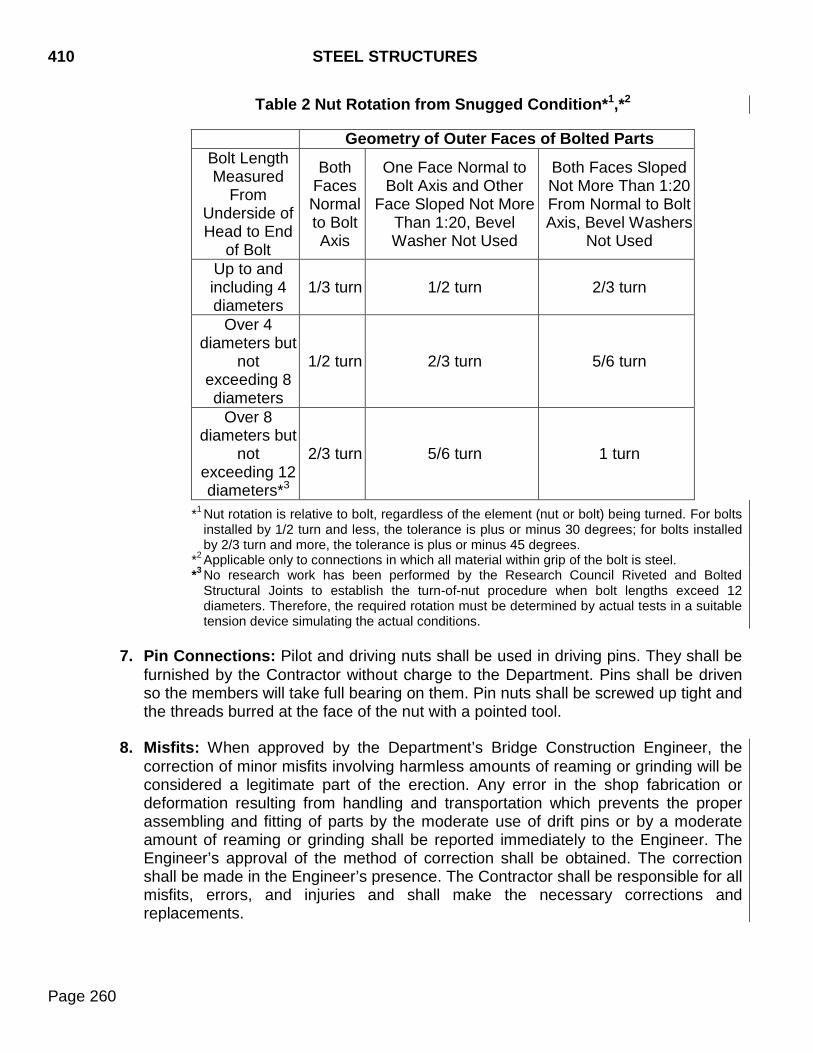
410 STEEL STRUCTURES
Page 260
Table 2 Nut Rotation from Snugged Condition*1,*2
Geometry of Outer Faces of Bolted Parts Bolt Length Measured
From Underside of Head to End
of Bolt
Both Faces Normal to Bolt Axis
One Face Normal to Bolt Axis and Other
Face Sloped Not More Than 1:20, Bevel Washer Not Used
Both Faces Sloped Not More Than 1:20 From Normal to Bolt Axis, Bevel Washers
Not Used
Up to and including 4 diameters
1/3 turn 1/2 turn 2/3 turn
Over 4 diameters but
not exceeding 8 diameters
1/2 turn 2/3 turn 5/6 turn
Over 8 diameters but
not exceeding 12 diameters*3
2/3 turn 5/6 turn 1 turn
*1 Nut rotation is relative to bolt, regardless of the element (nut or bolt) being turned. For bolts installed by 1/2 turn and less, the tolerance is plus or minus 30 degrees; for bolts installed by 2/3 turn and more, the tolerance is plus or minus 45 degrees.
*2 Applicable only to connections in which all material within grip of the bolt is steel. *3 No research work has been performed by the Research Council Riveted and Bolted
Structural Joints to establish the turn-of-nut procedure when bolt lengths exceed 12 diameters. Therefore, the required rotation must be determined by actual tests in a suitable tension device simulating the actual conditions.
7. Pin Connections: Pilot and driving nuts shall be used in driving pins. They shall be
furnished by the Contractor without charge to the Department. Pins shall be driven so the members will take full bearing on them. Pin nuts shall be screwed up tight and the threads burred at the face of the nut with a pointed tool.
8. Misfits: When approved by the Department’s Bridge Construction Engineer, the
correction of minor misfits involving harmless amounts of reaming or grinding will be considered a legitimate part of the erection. Any error in the shop fabrication or deformation resulting from handling and transportation which prevents the proper assembling and fitting of parts by the moderate use of drift pins or by a moderate amount of reaming or grinding shall be reported immediately to the Engineer. The Engineer’s approval of the method of correction shall be obtained. The correction shall be made in the Engineer’s presence. The Contractor shall be responsible for all misfits, errors, and injuries and shall make the necessary corrections and replacements.
STEEL STRUCTURES 410
Page 261
410.4 METHOD OF MEASUREMENT
Field measurement of structural steel will not be made. Adjustment in the contract price will not be made if the weight furnished is more or less than the estimated weight. The weights of rolled shapes, slabs, and plates will be computed on the basis of their nominal weights and dimensions. The weight will be computed on the following basis:
Unit weights of material in pounds per cubic foot:
Cast Iron ........................................................................................................ 445.0 Copper Sheet ................................................................................................ 558.0 Lead Sheet .................................................................................................... 707.0 Steel: cast, copper bearing, silicone, nickel, or stainless ............................... 490.0 Wrought Iron .................................................................................................. 487.0 Zinc ................................................................................................................ 450.0 Bronze or Copper-Alloy Bearing Plates ......................................................... 490.0
The quantities of the various other pay items, which constitute the completed and accepted structure, will be measured for payment according to the plans and specifications.
410.5 BASIS OF PAYMENT
Structural steel will be paid for at the contract lump sum price unless otherwise specified in the plans. Payment will be full compensation for furnishing, fabricating, delivery, erecting ready for use, for the required non-destructive weld testing by radiographing, magnetic particle, ultrasonic inspection, or other specified alternate test procedures. Payment shall also include painting of the structural steel, unless a separate bridge painting bid item is included in the contract. The cost of the required shear studs, bolts, nuts, washers, and direct tension indicators shall be incidental to the cost of the structural steel. If changes in the work, which vary the weight of steel to be furnished, are ordered the payment will be adjusted as follows: The value per pound of the increase or decrease in the weight of structural steel involved in the change shall be determined by dividing the contract lump sum amount by the estimate of weight shown on the plans. The overall contract payment will be the contract amount plus or minus the value of the steel involved in the change.
The accepted quantities will be paid for at contract unit price.

410 STEEL STRUCTURES
Page 262
THIS PAGE INTENTIONALLY LEFT BLANK
SHOP PAINTING 411
Page 263
411.1 DESCRIPTION
This work consists of shop cleaning metal surfaces and shop application of the specified coating system.
411.2 MATERIALS
Coatings, including primer, intermediate (if used), finish, and field repair coats shall all be from the same manufacturer and shall be one of the systems from the Department’s Approved Product List for shop paint (new construction).
411.3 CONSTRUCTION REQUIREMENTS
A. General: The coatings shall be applied in accordance with the manufacturer's recommendations. A written copy of the manufacturer’s recommendations, including product data sheet, shall be furnished to the Department prior to painting. The recommendations shall indicate the recommended minimum and maximum dry film thickness (DFT) for each coating layer of the system, mixing and thinning directions, recommended spray nozzles and pressures, minimum drying time, maximum time to recoat, cure time based on application temperature, maximum coating application temperature, and the recommended procedures for coating galvanized bearings, bolts, nuts, and washers. Coatings shall be shipped from the manufacturer with a date stamp to indicate expiration. Coatings outside of the expiration window shall not be used. Whenever the manufacturer’s recommendations are more stringent than the provisions of this section, the manufacturer’s recommendations shall apply. Coatings shall not be applied when the surface temperature is below 40°F or above 90°F, when the air is misty, when the humidity exceeds 85%, when the surface temperature is less than 5°F above the dew point, or when conditions are otherwise unsatisfactory. Coatings shall not be applied when the metal is hot enough to cause the paint to blister or produce a porous paint film. Coatings shall not be applied on damp or frosted surfaces. Coatings applied under cover in damp or cold weather shall remain under cover until dry or until weather conditions are suitable. Coatings shall be applied in a uniform, even coat and shall be worked into all corners and crevices. Coatings shall be applied with approved equipment. On surfaces which are otherwise inaccessible the coating may be applied with sheepskin daubers. Coatings that do not meet the requirements of this section shall be removed. The metal shall be reblasted, cleaned, and recoated at no expense to the Department. During coating application, scaffolding or other safe devices shall be provided to permit inspection of the steel. The Contractor shall provide protective devices as necessary to prevent damage to the work and to other property or persons from all cleaning and painting operations.
411 SHOP PAINTING
Page 264
Paint or paint stains that result in an unsightly appearance on surfaces not designated to be painted shall be removed or obliterated by the Contractor at the Contractor’s expense.
B. Coating New Structures:
1. Surface Preparation: Surfaces to be coated shall be abrasive blast cleaned to a near white finish, in accordance with SSPC SP 10. Abrasives used for blast cleaning shall be steel shot, mineral grit, or manufactured grit and shall have a gradation that provides a uniform steel surface profile of 1 to 3 mils. Air compressors used for surface preparation shall have a functioning moisture separator to reduce steel surface contamination.
Fins, tears, slivers, and burred or sharp edges shall be removed by grinding and the area reblasted to provide the profile specified.
Blast residue shall be removed from steel surfaces with a commercial grade vacuum cleaner equipped with a brush type cleaning tool, or by double blowing. Steel shall be kept dust free and dry. Steel shall be primed within 24 hours after cleaning.
2. Mixing and Thinning Paint: The coating shall be thoroughly mixed so the pigment
is completely in suspension and the consistency is uniform. The coating shall be strained over a sieve having openings no larger than a #50 sieve. After straining, the mixed coating shall be kept under continuous agitation until application is completed.
When thinning is necessary for proper application, it shall be accomplished in accordance with the manufacturer’s recommendations.
3. Coating Application: The prime coat, the intermediate coat (if used), and the finish
coat shall be applied in the shop, except where specified otherwise.
After the surface has been satisfactorily cleaned, the primer shall be applied producing a uniform even coating bonded with the metal. The finish coat shall not be applied until the prime and intermediate coats (if used) have been determined acceptable by the Department. The minimum curing time between coats shall be as recommended by the manufacturer. Coatings shall be applied in accordance with SSPC PA1.
Surfaces to be coated include contact surfaces of bolted field splices. The dry film thickness (DFT) of the prime coat, intermediate coat (if used), and top coat shall meet the manufacturer’s recommendations. The contact or faying surfaces of bolted field splices, bolted shop splices, and any other bolted faying surface, shall be given a prime coat only and masked during subsequent coating operations. DFT shall be measured in accordance with SSPC PA 2. When measuring DFT in accordance with SSPC PA 2, the areas to be measured shall be set up to ensure the total DFT (primer, intermediate (if used), and top coat) is not less than the DFT recommended
SHOP PAINTING 411
Page 265
by the manufacturer on the following surfaces: top of the bottom flange, top of horizontal stiffeners, and top surfaces of diaphragms. Bolted shop connections and bolted cross frames or diaphragms shall be removed and disassembled prior to the abrasive blasting and coating of the girders. The removed parts shall be abrasive blasted and primed separately, allowed to dry, reassembled, and the bolts fully tightened. Galvanized components; including nuts, bolts, and washers shall be cleaned after assembly with a mineral spirit solvent followed by a hot water rinse and thorough drying, given a prime coat, an intermediate coat (if used), and then coated with the finish coat. To avoid runs, bubbles, and sags each coat shall be applied in multiple passes of the spray gun (mist coat) with each pass separated by several minutes. If applying a polyurethane top coat over an inorganic zinc primer, a mist coat is required. Where excessive coating thickness produces “mud cracking”, the coating shall be scraped back to soundly bonded coating and the area recoated. Areas of deficient primer thickness shall be thoroughly cleaned with power washing equipment to remove all dirt. The area shall then be wire brushed, vacuumed, and recoated. Each member shall have an erection mark for field identification. A diagram shall be furnished showing the erection marks. The mark shall not be visible after erection.
4. Handling and Shipping: Material shall not be loaded for shipment until the shop
coating has been determined acceptable by the Department. Extreme care shall be exercised in handling the steel in the shop, during shipment, during erection, and during subsequent construction of the bridge to prevent damage to the coating. Overhang brackets shall be padded where they bear on the web. Deck formwork shall be mortar tight to prevent leakage onto the girders. The coating shall be protected from all chains, slings, hooks, and other apparatus used to lift or turn the coated steel. During shipment, padding shall be used to prevent damage from rubbing and other causes. Diaphragms and other parts shall be padded and packed to prevent damage. The steel shall be stored off the ground on padded supports to prevent damage. Girders shall be stored so they cannot fall on or touch one another. The steel shall not be shipped until the contractor has the necessary equipment for handling and storing the steel. The Contractor's proposed methods for handling and storing the steel will be discussed at the preconstruction meeting.
5. Field Repair: All field repairs shall be made in accordance with the manufacturer's
recommendations. Field repairs shall consist of application of a prime coat, an intermediate coat (if used), and a finish coat. Paint used for field repairs shall be the same paint system as the paint applied in the shop. Field repair shall be accomplished after the deck is poured and falsework removed and includes painting galvanized bolts, primed areas of splice plates, diaphragm connections, and other
411 SHOP PAINTING
Page 266
areas requiring touch up or finish painting. Faying surfaces of bolted connections, including splice plates, shall be coated only with the primer.
The structural steel shall have oil and grease removed by wiping with clean rags soaked in an appropriate solvent in accordance with SSPC SP1. The steel surfaces shall then be power tool cleaned in accordance with SSPC SP3 to provide a rust-scale free surface. Abrasive blast cleaning as per SSPC SP6 shall be required on areas where heavy rusting is causing rusting scale.
After satisfactory surface preparation has been completed, the steel shall be given a prime coat. After the prime coat has properly cured, an intermediate coat (if used) shall be applied. After the intermediate coat (if used) has properly cured, a finish coat shall be applied. The DFT of the prime coat, intermediate coat (if used), and top coat shall meet the manufacturer’s recommendations. Coatings shall be applied in accordance with SSPC PA1. DFT shall be measured in accordance with SSPC PA2. The prime coat, intermediate coat (if used), and finish coat may be applied by spraying, brushing, or rolling as determined by manufacturer’s recommendations. The contact or faying surfaces of bolted field splices, bolted shop splices, and any other bolted faying surface, shall be given a prime coat only.
C. Repainting Existing Structures: Repainting existing structures shall conform to Section 412.
411.4 METHOD OF MEASUREMENT
Measurement for the item Bridge Painting will not be made.
411.5 BASIS OF PAYMENT
Bridge Painting will be paid for at the contract lump sum price. Payment will be full compensation for surface preparation, furnishing and applying the coating, field repair of damaged or uncoated areas, and other incidentals required.
BRIDGE FIELD PAINTING, REPAINTING, 412 AND PAINT RESIDUE CONTAINMENT
Page 267
412.1 DESCRIPTION
This work consists of the removal, containment, and disposal of existing paint on steel surfaces, preparing the steel surfaces, and the field painting/repainting of steel surfaces.
412.2 MATERIALS
A. Solvent Cleaners: Shall be as recommended by the paint manufacturer.
B. Paint System: Coatings, including primer, top coat, and field repair coats shall be from
the same manufacturer and, unless otherwise specified, shall be one of the systems from the Department’s Approved Products List for bridge field paint. The Contractor shall supply the Engineer with a copy of the manufacturer’s data sheets prior to painting.
C. Paint Color: When only spot painting the work affected areas, the contractor shall obtain a paint chip sample from the structure and submit the structure sample and a paint chip from the paint supplier to the Office of Bridge Design for approval.
Prime Coat: The prime coat color shall sharply contrast with the top coat, as approved by the Engineer. Intermediate Coat (if used): The intermediate coat (if used) color shall sharply contrast with the top coat, as approved by the Engineer. Top Coat: The color shall match existing paint unless otherwise specified.
412.3 CONSTRUCTION REQUIREMENTS
A. Surface Preparation and Painting: Unless otherwise specified in the plan notes, the following requirements shall apply to field painting and bridge repainting, Class I and Class II, as identified in the plans.
1. Solvent Cleaning: The affected areas shall be visually inspected for contamination
of oils and greases prior to removal of the existing paint. When contamination is found on any of the areas that will be painted, the affected area shall be cleaned with solvent soaked rags and dried with clean rags.
2. Surface Preparation:
a. New Steel to be Field Painted: When new steel is to be field painted, the steel
surfaces to be painted shall be prepared in accordance with the following: 1) Following any solvent cleaning required, surfaces to be coated shall be
abrasive blast cleaned to a condition equivalent to SSPC SP-6 (Commercial Blast Cleaning).
412 BRIDGE FIELD PAINTING, REPAINTING, AND PAINT RESIDUE CONTAINMENT
Page 268
Abrasive for blast cleaning shall be either steel shot, mineral grit, or manufactured grit and shall have a gradation that provides a uniform steel surface profile. The bare steel shall be prepared to have a surface profile of 1 mil minimum and 3 mils maximum, prior to application of the prime coat. The surface profile obtained on the prepared surface will be verified by ASTM Specification D4417 "Standard Test Method Field Measurements of Surface Profile of Blast Cleaned Steel" Method A, B, or C. If the surface profile cannot be maintained below the maximum limit specified, the final coating thickness shall be increased to ensure that the minimum coating thickness is achieved over the entire area to be painted.
2) Fins, tears, slivers, and burred or sharp edges shall be removed by grinding
and the area reblasted to provide the profile specified.
3) Blast residue shall be removed from the steel surfaces with a commercial grade vacuum cleaner equipped with a brush type cleaning tool, or by two applications of blowing with compressed air.
4) Steel surfaces shall be kept clean, dust free, and dry. Steel surfaces shall be
primed within 24 hours of abrasive blast cleaning. b. Bridge Repainting, Class I: When bridge repainting, Class I is specified, the
steel surfaces to be painted shall be prepared in accordance with the following:
1) Following any required solvent cleaning, all loose rust and paint shall be removed from the work affected areas by power tool cleaning. The entire surface to be painted shall be prepared to a condition equivalent to SSPC Standard SP-3 (power tool cleaning). All power tools shall be shrouded at the cleaning head and equipped with a vacuum collection system to contain the paint residue. The power tool cleaning shall not remove any base metal.
2) Contain and collect all existing paint residue in accordance with Section 412.3
B. c. Bridge Repainting, Class II: When bridge repainting, Class II is specified, the
steel surfaces to be painted shall be prepared in accordance with the following:
1) Following any required solvent cleaning, abrasive blast clean the steel surfaces to remove all old paint, corrosion, and mill scale. To minimize the potential for the abrasive blasting media and paint residue being a hazardous material, the abrasive blasting process shall utilize a thoroughly mixed blend of abrasive blasting media and Blastox (or other approved product). The Blastox shall be added in the amount of 15% by weight. The abrasive media used in the abrasive blasting process shall be a silica free abrasive and shall be of a type and size in which the formation of dust during the abrasive blasting process is minimized. The entire surface to be painted shall be cleaned to a condition equivalent to the SSPC Standard SP-6 (commercial blast cleaning).
BRIDGE FIELD PAINTING, REPAINTING, 412 AND PAINT RESIDUE CONTAINMENT
Page 269
2) The bare steel shall be prepared to have a surface profile of 1 mil minimum
and 3 mils maximum prior to application of the prime coat. The surface profile obtained on the prepared surface will be verified by ASTM Specification D4417 "Standard Test Method Field Measurements of Surface Profile of Blast Cleaned Steel" Method A, B, or C. If the surface profile cannot be maintained below the maximum limit specified, the final coating thickness shall be increased to ensure that the minimum coating thickness is achieved over the entire area to be painted.
3) The cleaned areas shall be thoroughly dry before priming.
4) Do not clean a larger area than can be prepared and primed within 24 hour
period. If the prepared area is not primed within the 24 hours, the area shall have the blast cleaning repeated.
5) Contain and collect all of the existing paint residue and abrasive blasting
media according to Section 412.3 B.
3. Mixing of Paint: The paint shall be thoroughly mixed with a power mixer in accordance with the manufacturer’s recommendations before being applied and the pigments shall be kept in suspension. The manufacturer's recommended pot life times shall not be exceeded.
4. Paint Application: After the specified surface preparation, the paint shall be applied
according to the following requirements:
a. The coating thickness shall meet the dry film thickness (DFT) recommended by the manufacturer. DFT shall be measured in accordance with SSPC PA 2.
b. Coatings shall be applied in accordance with SSPC PA1, the manufacturer’s
written recommendations, or the requirements as herein specified, whichever is more stringent. A copy of the manufacturer's written instructions shall be given to the Engineer prior to painting.
c. Remove all overspray, drips, and spills at no cost to the Department.
d. Apply paint only when the surface to be coated is and remains at least 5°F above
the dew point. The relative humidity shall be less than 85% during paint application. Apply paint only when the coating materials, substrate, and air temperature are between 40°F and 90°F. Coatings shall not be applied on damp or frosted surfaces. Coatings applied under cover in damp or cold weather shall remain under cover until dry or until weather conditions are suitable. Coatings shall not be applied when the metal is hot enough to cause the paint to blister or produce a porous paint film.
e. Do not use thinners unless absolutely necessary for paint application. Do not
exceed the manufacturer's recommendations with regard to quantity and type of
412 BRIDGE FIELD PAINTING, REPAINTING, AND PAINT RESIDUE CONTAINMENT
Page 270
thinner. Use thinners only according to the manufacturer's written instructions, and under the Engineer's supervision.
f. Using a brush, stripe coat the edges and corners of all metal work, rivet heads,
bolts, nuts, other hardware and fasteners, and all individual members, bars, shapes, and plates prior to the application of the primer, intermediate (if used), and top coats.
g. The Contractor shall protect pedestrian, vehicular, watercraft, and other traffic
upon or underneath the structure and all portions of the structure against damage or disfigurement by paint overspray. When painting over waterways the Contractor shall implement such controls as are necessary to avoid paint spills into the water or depositing paint films on the water during spraying operations.
B. Paint Residue Containment, Collection, and Storage:
1. Bridge Repainting, Class I: The existing paint residue on the surfaces to be
painted shall be contained, collected, and stored according to the plan notes and the following requirements:
a. All paint residue shall be placed in a 55 gallon drum after collection. The 55
gallon drum shall be supplied by the Contractor and shall become the property of the Department. If the 55 gallon drum is not new, it shall not have previously contained any petroleum products and must meet the EPA definition of a reusable container. All paint removal, residue collection, and temporary storage shall be performed by the Contractor. Disposal will be performed by the Department.
b. When bridge repainting, Class I is specified, it is anticipated that less than 220
pounds of paint residue will be produced. Therefore, the waste will not require sampling, testing, and disposal as a hazardous waste. The Contractor must collect and weigh all paint residue to document that less than 220 pounds of waste material was produced. If more than 220 pounds of waste material is produced the Office of Bridge Design shall be contacted immediately for further instructions.
c. The Contractor shall not place materials or trash other than paint residue, rags containing solvent or paint residue, and blasting media in the barrels.
d. The Contractor is responsible for complying with all regulations and for taking all
necessary measures and precautions to ensure worker safety for work involving lead particles.
2. Bridge Repainting, Class II: The existing paint residue on the work affected areas
shall be contained, collected, and stored according to the plan notes and the following requirements:
BRIDGE FIELD PAINTING, REPAINTING, 412 AND PAINT RESIDUE CONTAINMENT
Page 271
a. The Contractor shall contain, collect, and temporarily store all paint residue and blasting media. The material shall then be loaded, transported to the location specified in the plans, and unloaded by the Contractor.
b. The Contractor shall use Best Management Practices, as defined by the
Environmental Protection Agency, to contain and collect all paint residue removed from the steel surfaces and all abrasives used in blast cleaning. Containment and collection of the abrasives used in blast cleaning is required, even when not mixed with paint residue.
c. When bridge repainting, Class II is specified, it is anticipated that more than 220
pounds of paint residue and blasting residue will be produced. Therefore, the residue material shall be sampled and tested to determine if it is a hazardous waste. When the first 55 gallon drum is filled, the Engineer will collect a sample and immediately submit the sample to the Department’s Bridge Construction Engineer.
d. The Contractor shall submit a written Containment Plan to the Engineer at the
preconstruction meeting. The Engineer will forward the proposed Containment Plan to the Office of Bridge Design for review and approval. Possible containment methods include draped collectors suspended from the structure, tarps laid on the ground below the structure (when not near a waterway or in an urban environment), complete enclosures, and shrouded power tools with vacuum containment.
e. If a draped collector is used it shall conform to the following minimum
requirements:
1) The collector shall be suspended from the structure and shall extend a minimum of 10 feet in all directions, than the area in which work is underway.
2) The collector shall be positioned in a manner acceptable to the Engineer and
such that no loss of blast cleaning/paint residue occurs.
3) The collector shall be emptied at least once a day and shall not remain in place overnight without being emptied.
f. Blast cleaning and other operations shall not be performed when the direction
and velocity of the wind is such that residue falls outside the limits of the collector.
g. The Contractors Containment Plan shall outline the procedures that will be
followed to empty the collector and prevent spilling of the contents.
h. Paint residue, including abrasive blasting residue, shall be placed in 55 gallon drums after collection. The 55 gallon drums shall be supplied by the Contractor and shall become the property of the Department. If the 55 gallon drums are not
412 BRIDGE FIELD PAINTING, REPAINTING, AND PAINT RESIDUE CONTAINMENT
Page 272
new, the drums shall not have previously contained petroleum products. The drums shall meet the EPA definition of a reusable container.
i. Only paint residue, blasting media, and solvent soaked rags are allowed to be
placed in the containment drums. These drums shall not be used for other garbage or waste.
j. The 55 gallon drums shall be filled, properly sealed, temporarily stored, loaded,
hauled to the location specified in the plans, and unloaded by the Contractor. Temporary storage of the material on the site shall be at a location where there is no possibility of a spill entering any waterway.
k. Until test results are obtained to substantiate that the material is not hazardous,
each 55 gallon drum shall be marked with the words "Hazardous Waste" and shall be dated with the date on which the drum was filled. This shall be done by using a permanent, waterproof marker.
l. Disposal of the barrels containing the paint residue and blasting media will be the
responsibility of the Department.
m. If the Contractor elects to use containers other than 55 gallon drums to hold paint residue, the Contractor shall be responsible for all testing and disposal at a permitted regional landfill. The Contractor shall be responsible for compliance of laws and regulations regarding storage, handling, and shipping. The containers shall be watertight and have a lid. The Contractor shall mark the containers with the words “Hazardous Waste”. Containers shall be stored in a locked enclosure. Copies of all tests, shipping, and disposal documents shall be provided to the Office of Bridge Design.
n. The Contractor is responsible for complying with all regulations and for taking all
of the necessary measures to ensure worker safety for work involving lead particles.
C. Inspection: All materials and work shall be subject to inspection by the Department.
The Contractor shall provide the Engineer adequate and safe access to the work area, including ladders and scaffolding, at all times.
When bridge repainting, Class II is specified, the Contractor shall blast a test area of a girder web to SSPC Standard SP-6, prior to the start of the abrasive blast cleaning operations. This test area shall be full depth of the web and shall be three feet in length. Using the visual and profile standards, the Engineer will inspect the area to determine when adequate surface preparation has been achieved. After adequate surface preparation has been achieved, this area shall be preserved for reference purposes during the remainder of the abrasive blast cleaning operation. If deterioration of this area occurs due to weathering, dampness, or other conditions, a new area shall be prepared at no additional cost to the Department.
BRIDGE FIELD PAINTING, REPAINTING, 412 AND PAINT RESIDUE CONTAINMENT
Page 273
412.4 METHOD OF MEASUREMENT
Measurement for the items field painting, bridge repainting, and paint residue containment will not be made.
412.5 BASIS OF PAYMENT
A. Bridge Repainting, Class I and Bridge Repainting, Class 2 will be paid for at the contract lump sum price. Payment will be full compensation for surface preparation, furnishing and applying the coating system, repair of damaged areas, cleanup, providing inspection access, and all incidentals to satisfactorily complete the work.
B. Paint Residue Containment will be paid for at the contract lump sum price. Payment
will be full compensation for all direct and incidental costs to remove, contain, and temporarily store paint residue. When specified in the plan notes, payment will also be full compensation for loading the residue, transporting the residue to the location specified, and unloading the residue.

412 BRIDGE FIELD PAINTING, REPAINTING, AND PAINT RESIDUE CONTAINMENT
Page 274
THIS PAGE INTENTIONALLY LEFT BLANK
STRUCTURE EXCAVATION 420
Page 275
420.1 DESCRIPTION This work consists of the necessary foundation excavation for box culverts and bridges.
420.2 MATERIALS (Not Specified) 420.3 CONSTRUCTION REQUIREMENTS
A. Depth of Excavation: The elevations of the bottoms of footings shown on the plans are approximate and the Engineer may order, in writing, such changes in elevations of footings as necessary.
B. Treatment of Foundation: Rock or other hard foundation material shall be free of loose
material, cleaned, and cut to a firm surface. The surface may be level, stepped, or serrated as approved by the Engineer.
Where concrete is placed on an excavated surface other than rock, special care shall be taken not to disturb the bottom of the excavation. Concrete shall not be placed until the depth of excavation has been checked and the suitability of the foundation material approved.
Foundation excavation may be trimmed to the exact size of the footing and the footing forms omitted, when approved by the Engineer. Removal of unstable material below the bedding grade of box culverts shall be performed as set forth in Section 421. Where foundation piles are used, the excavation of each foundation bed shall be completed before the piles are driven. After the pile driving is completed, loose and displaced material shall be removed or compacted to a smooth solid bed at or below plan elevation.
C. Disposal of Excavation Material: The excavated material shall be used for backfill and
embankment or disposed of as directed. Excavated material shall not be placed in stream beds.
D. Preservation of Channels: Excavation shall not be made outside of caissons, cribs,
cofferdams, steel piling, or sheeting and the natural stream bed adjacent to the structure shall not be disturbed. If any excavation or dredging is done at the site of the structure before caissons, cribs, or cofferdams are in place, the Contractor shall backfill all excavation to the original ground surface or stream bed with satisfactory material after the foundation is in place.
E. Cofferdams and Cribs: Cofferdams and cribs shall conform to the requirements of
Section 423.
420 STRUCTURE EXCAVATION
Page 276
F. Inspection: The Engineer shall be notified as soon as each excavation is completed. Concrete or piling shall not be placed until the Engineer determines that the depth and size of the excavation and the foundation material are acceptable.
G. Backfill above Bedding Grade: Material used for backfill shall be of an acceptable
quality and shall be free from large or frozen lumps, wood, and other extraneous material.
Spaces not occupied by abutments, piers, or other permanent work shall be backfilled to match the surface of the surrounding ground, with a sufficient allowance for settlement. Backfill shall be satisfactorily compacted in horizontal layers not to exceed 6 inches loose depth. The slope bounding the excavation for abutments and wingwalls shall be stepped or roughened to prevent wedge action of the backfill against the concrete. Backfill placed around box culverts, columns, piers, and walls shall be deposited equally on both sides of the structure. Backfill shall be compacted in accordance with Section 120.
420.4 METHOD OF MEASUREMENT
Excavation for drilled-in foundations will be measured as set forth on the plans.
The removal of water will not be considered a measurable item nor will allowance be made for duplication, sloughed material, or material removed due to mud flows. The plan shown quantity will be the quantity accepted for payment. Field measurements for structure excavation quantities will not be made, unless the Department determines that conditions warrant such measurement. Structure excavation will be measured to the nearest cubic yard. A. Structure Excavation, Bridge: The volume of an old structure or the volume of
excavation performed as part of the removal of an old structure will be included in the pay quantity of excavation for the new bridge. The excavation allowed above the plan shown bedding grade for piers and abutments will be that volume bounded by vertical planes 18 inches outside of and parallel to the neat lines of the footings regardless of the volume of material actually excavated. Authorized excavation below the plan shown bedding grade will be that volume actually removed within the limits bounded by vertical planes 18 inches outside of and parallel to the neat lines of the footings. When foundation piles are used, no measurement will be made for excavation below the plan shown bedding grade unless the Engineer orders the foundation lowered.
Measurement will not be made for excavation necessary for foundation seals.
STRUCTURE EXCAVATION 420
Page 277
The plan shown line denoting the lower limit of unclassified excavation, or the as constructed line in the event it is lower, will be considered the upper limit for structure excavation with the following exceptions: The existing ground line will be considered the upper limit for structure excavation if, at the time of foundation excavation, the existing ground line is lower than the plan shown line denoting the lower limit of unclassified excavation or a line denoting the lower limit of unclassified excavation is not shown on the plans.
B. Structure Excavation, Box Culvert: When a box culvert is constructed at or above the specified flow line, the plan shown quantity of structure excavation will be the pay quantity. This quantity of excavation is equal to the theoretical volume of concrete below the box culvert flow line.
When the Engineer orders the box culvert flow line lowered on construction, the material excavated between the plan shown box culvert flow line and the as constructed box culvert flow line will be measured for payment as unclassified excavation unless it is unstable material and must be removed by a dragline, backhoe, or similar equipment in which case it will be measured as structure excavation.
C. Structure Excavation, Retaining Wall: Measurement will not be made for structure
excavation, retaining wall. Plans quantity shall be used for payment.
D. Structure Excavation, Miscellaneous: Measurement will not be made for structure excavation, miscellaneous. Plans quantity shall be used for payment.
420.5 BASIS OF PAYMENT
Payment for work under this item will be made at the contract unit price per cubic yard for structure excavation, bridge; structure excavation, box culvert; structure excavation, retaining wall; or structure excavation, miscellaneous. In the case of piers and abutments for bridges, excavation ordered by the Engineer below the plan shown bedding grade will be paid for in accordance with Section 9.5. In the case of box culverts, payment for excavation of unstable material which must be removed by means of a dragline, backhoe, or similar equipment will be as per Section 421.5. Work that is classed as unclassified excavation will be paid for at the contract unit price for unclassified excavation, or as extra work when an item of unclassified excavation is not provided in the contract. Payment will be considered full compensation for furnishing materials, labor, equipment, tools, and incidentals, including furnishing, installing, and removing any cofferdams, cribs, sheeting, or other temporary works necessary to complete the work.

420 STRUCTURE EXCAVATION
Page 278
THIS PAGE INTENTIONALLY LEFT BLANK
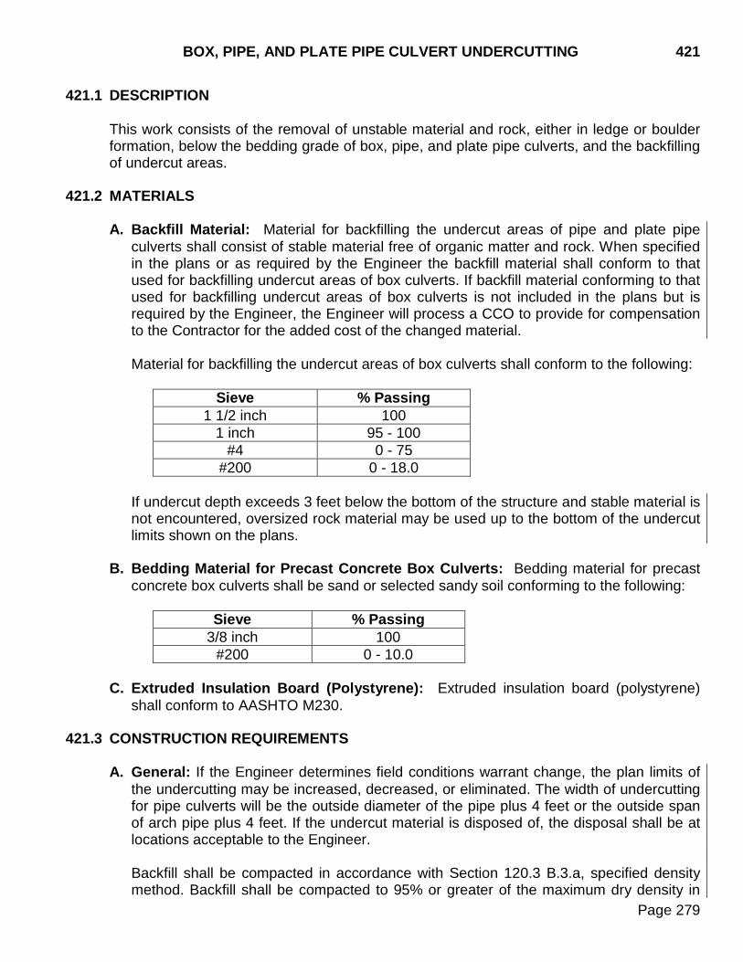
BOX, PIPE, AND PLATE PIPE CULVERT UNDERCUTTING 421
Page 279
421.1 DESCRIPTION
This work consists of the removal of unstable material and rock, either in ledge or boulder formation, below the bedding grade of box, pipe, and plate pipe culverts, and the backfilling of undercut areas.
421.2 MATERIALS
A. Backfill Material: Material for backfilling the undercut areas of pipe and plate pipe culverts shall consist of stable material free of organic matter and rock. When specified in the plans or as required by the Engineer the backfill material shall conform to that used for backfilling undercut areas of box culverts. If backfill material conforming to that used for backfilling undercut areas of box culverts is not included in the plans but is required by the Engineer, the Engineer will process a CCO to provide for compensation to the Contractor for the added cost of the changed material.
Material for backfilling the undercut areas of box culverts shall conform to the following:
Sieve % Passing
1 1/2 inch 100 1 inch 95 - 100
#4 0 - 75 #200 0 - 18.0
If undercut depth exceeds 3 feet below the bottom of the structure and stable material is not encountered, oversized rock material may be used up to the bottom of the undercut limits shown on the plans.
B. Bedding Material for Precast Concrete Box Culverts: Bedding material for precast concrete box culverts shall be sand or selected sandy soil conforming to the following:
Sieve % Passing
3/8 inch 100 #200 0 - 10.0
C. Extruded Insulation Board (Polystyrene): Extruded insulation board (polystyrene)
shall conform to AASHTO M230. 421.3 CONSTRUCTION REQUIREMENTS
A. General: If the Engineer determines field conditions warrant change, the plan limits of the undercutting may be increased, decreased, or eliminated. The width of undercutting for pipe culverts will be the outside diameter of the pipe plus 4 feet or the outside span of arch pipe plus 4 feet. If the undercut material is disposed of, the disposal shall be at locations acceptable to the Engineer.
Backfill shall be compacted in accordance with Section 120.3 B.3.a, specified density method. Backfill shall be compacted to 95% or greater of the maximum dry density in
421 BOX, PIPE, AND PLATE PIPE CULVERT UNDERCUTTING
Page 280
horizontal layers not to exceed 6 inches loose depth. If the backfill material does not contain enough fines to allow for conventional density testing (SD 105 or SD 106), the natural material will be compacted in the manner described in Section 120.3 B.3.a for A-2-4(0) and A-3 soils. Compaction of A-2-4(0) and A-3 soils shall provide a firm, unyielding surface satisfactory to the Engineer.
B. Box Culvert: Undercut dimensions shall be to the minimum dimensions shown on the
plans, unless otherwise directed by the Engineer.
C. Pipe Culvert: A moisture/density test is required in the foundation soil under all rural mainline cross pipes prior to installation. The foundation soil density will be in accordance with the specified density method. The foundation soil will be improved by one of the following methods, as directed by the Engineer.
1. Scarifying the foundation soil to a depth of 6 to 8 inches and recompacting. 2. Undercutting the foundation soil and replacing or recompacting. Under this item of work, the removal of unstable material, ledge rock, and boulder formation rock below the bedding grade of pipe culverts and the backfilling of undercut areas shall be performed. Pipe culverts placed on embankment soil (in the fill and not on natural ground) will not require pre-installation testing of the foundation soil provided that the fill area has been included in normal embankment testing zones. The Engineer may order undercutting of pipe not included in the plans.
D. Extruded Insulation Board (Polystyrene): No equipment will be allowed on the uncovered insulation board. The backfill covering the insulation board shall be spread and compacted in such a manner that the equipment used shall be operated on a minimum of 6 inches of backfill material at all times.
421.4 METHOD OF MEASUREMENT
A. Box Culvert Undercut: Undercutting box culverts will be measured by the cubic yard. The upper limit will be the bedding grade of the box culvert. The dimensions and lower limits will be as specified on the plans unless otherwise directed by the Engineer.
B. Pipe and Plate Pipe Culvert Undercut: Undercutting pipe and plate pipe culverts will
be measured by the cubic yard. The upper limit will be the lower face of the pipe, except the upper limit for pipe culverts to be installed on a Class B bedding will be 1 foot below the lower face of the pipe. The width, length, and lower limits will be as specified.
C. Extruded Insulation Board (Polystyrene): Extruded insulation board (polystyrene) will
be measured to the nearest square yard.
BOX, PIPE, AND PLATE PIPE CULVERT UNDERCUTTING 421
Page 281
421.5 BASIS OF PAYMENT
A. Box Culvert Undercut: This work will be paid for at the contract unit price per cubic yard, under the item box culvert undercut. The basis of payment will be for plans quantities unless additional undercutting is directed by the Engineer. When additional undercutting is required, the adjusted quantity of undercutting will be paid for at the contract unit price regardless of the backfill material used. Payment will be full compensation for equipment, labor, tools and incidentals required for undercutting and for furnishing, placing, watering and compacting backfill material, including bedding material when specified on the plans.
B. Pipe and Plate Pipe Culvert Undercut: This work will be paid for at the contract unit
price per cubic yard, under the item pipe culvert undercut. All costs for undercutting pipe culverts including equipment, labor, tools, and materials for furnishing, placing, watering, and compacting backfill in place of excavated material shall be incidental to the contract unit price for pipe culvert undercut. The quantities listed in the table of pipe culvert undercut are based on the undercut width specified above, and a depth of 1 foot for all pipes 36 inches in diameter and greater. When undercutting culverts is required at other locations or to a different depth than specified, the adjusted quantity of undercutting will be paid for at the contract unit price. Undercutting pipe and plate pipe culverts will be paid for at the rate specified in the Special Provision for Price Schedule For Miscellaneous Items.
All costs for scarifying the foundation soil including equipment, labor, watering, and compacting the scarified soil shall be incidental to the contract unit price per foot for pipe culvert installation.
C. Extruded Insulation Board (Polystyrene): Extruded insulation board (polystyrene) will be paid for at the contract unit price per square yard. Payment shall be full compensation for labor, equipment, and incidentals to furnish and install the extruded insulation board (polystyrene).

421 BOX, PIPE, AND PLATE PIPE CULVERT UNDERCUTTING
Page 282
THIS PAGE INTENTIONALLY LEFT BLANK
DRAINAGE FABRIC PROTECTION FOR CAST IN PLACE 422 REINFORCED CONCRETE BOX CULVERTS
Page 283
422.1 DESCRIPTION
This work consists of placement of drainage fabric protection around the outside of all cast in place reinforced concrete box culvert joints.
422.2 MATERIALS
Drainage Fabric: Drainage Fabric shall conform to Section 831, Type A. 422.3 CONSTRUCTION REQUIREMENTS
Drainage fabric shall be placed entirely around each joint in the box culvert barrel. The fabric shall be placed to provide a minimum of 2 1/2 feet of fabric centered on the joint. Where required, transverse joints in the fabric shall be overlapped a minimum of 2 feet. During bottom slab construction the fabric shall be placed prior to concrete placement. Sufficient adhesive will be required along the edges of the fabric to hold it in place during backfilling.
422.4 METHOD OF MEASUREMENT
Separate measurement will not be made. 422.5 BASIS OF PAYMENT
Separate payment will not be made. The cost of providing drainage fabric will be incidental to other contract items.
422 DRAINAGE FABRIC PROTECTION FOR CAST IN PLACE REINFORCED CONCRETE BOX CULVERTS
Page 284
THIS PAGE INTENTIONALLY LEFT BLANK
TEMPORARY WORKS 423
Page 285
423.1 DESCRIPTION
This work consists of the design, construction, and subsequent removal of all temporary works including, but not limited to; falsework, formwork, cofferdams, work berms and platforms, temporary traffic and stream diversions, and temporary retaining structures.
423.2 MATERIALS (Not Specified) 423.3 CONSTRUCTION REQUIREMENTS
A. Design of Temporary Works: The design of falsework, formwork, temporary retaining structures, and other related temporary works is the responsibility of the Contractor. The design shall conform to the latest edition of the AASHTO "Guide Design Specification for Bridge Temporary Works." All temporary works in waters of the US are required to be covered in the Corp of Engineers 404 Permit. At the time of the preconstruction meeting, the Contractor shall submit documentation for all temporary works for the purpose of complying with the 404 Permit requirements. The documentation shall include at a minimum: 1. A written description of the proposed temporary works including types of materials to
be used, how the temporary works will be installed, removed, and what portion, if any, will remain in place after construction;
2. Details showing approximate size and location of the temporary works. Details shall
include at a minimum, a plan view and a cross-section view of the temporary works. Details shall provide sufficient dimensions such that the approximate size of the temporary works and location of the temporary works from a known point is shown; and,
3. Estimated quantities of all temporary fill material below the ordinary high water
elevation. If the temporary fill is to be placed in a wetland, the estimated quantity shall be the amount of temporary fill below the ordinary high water elevation and the amount of wetland loss (in acres).
If during the course of construction there is a need for additional temporary works, the documentation shall be submitted to the Engineer at that time. The Engineer will submit the documentation to the Corp of Engineers for approval. Construction of temporary works below the ordinary high water mark or in wetlands may not begin until Corps of Engineers approval is attained by the Engineer.
B. Structure Falsework: Falsework plans and design calculations for structures shall be
prepared by a Professional Engineer registered in the State of South Dakota. The Contractor shall submit detailed and dimensioned falsework plans with full design calculations to the Department for the Department’s review and approval. Falsework plans shall include a plan and elevation view and any details necessary for the Department to check the design. The falsework plan shall include a minimum 2 foot

423 TEMPORARY WORKS
Page 286
walkway on both sides outside the edge of the concrete pour. For concrete slab bridges, the total dead load deflection shall not exceed 1/4 inch. The Contractor shall send an email with the falsework plans and design calculations attached as two separate PDFs to the Project Engineer and Office of Bridge Design. Upon request, the Project Engineer will provide the Contractor the appropriate email addresses. Within 28 calendar days of receiving the initial falsework plans and design calculations, the Office of Bridge Design will send a response to the Contractor with the Department’s final approval or one reviewed copy of the falsework plans and design calculations with changes to the design marked. The Contractor will make the necessary changes, if any, to the falsework plans and design calculations. The Contractor will then send the Project Engineer and the Office of Bridge Design an email with the final approved falsework plans and design calculations as a PDF for distribution. No falsework construction shall be done until the Department’s review has been made and all deficiencies have been addressed. The review of the falsework plans by the Department shall not relieve the Contractor of any responsibility for safely and adequately designing and constructing falsework.
Falsework shall be constructed in accordance with the reviewed falsework plans. Before placing any loads on the falsework, the Contractor shall provide the Engineer written certification from the Contractor’s Professional Engineer stating that the falsework has been assembled in conformance with the approved falsework plans. If field changes are made during falsework construction, new falsework plans prepared by a Professional Engineer registered in the State of South Dakota shall be submitted to the Project Engineer and Office of Bridge Design for review. Falsework construction affected by the change shall not continue until the change is approved and the Contractor has submitted a revised written certification. The Engineer may refuse approval to proceed with other phases of the work if the falsework is determined to be unsafe or inadequate to properly support construction loads.
C. Cofferdams, Cribs, and Shoring: Cofferdams, cribs, and shoring plans with design
calculations shall be prepared by a Professional Engineer registered in the State of South Dakota. The Contractor shall submit detailed and dimensioned cofferdams, cribs, and shoring plans with full design calculations to the Department for the Department’s review and approval. Cofferdams, cribs, and shoring plans shall include any details necessary for the Department to check the design. The Contractor shall send an email with the cofferdams, cribs, and shoring plans and design calculations attached as two separate PDFs to the Project Engineer and Office of Bridge Design. Upon request, the Project Engineer will provide the Contractor the appropriate email addresses. Within 28 calendar days of receiving the initial cofferdams, cribs, and shoring plans with design calculations, the Office of Bridge Design will send a response to the Contractor with the Department’s final approval or one reviewed copy of the cofferdams, cribs, and shoring plans and design calculations with changes to the design marked. The Contractor will make the necessary changes, if any, to the cofferdams, cribs, and shoring plans and design calculations. The Contractor will then send the Project Engineer and the Office of Bridge Design an email with the final approved cofferdams, cribs, and shoring plans and design calculations as a PDF for distribution. No cofferdams, cribs, or shoring
TEMPORARY WORKS 423
Page 287
construction shall be done until the Department’s review has been made and all deficiencies have been addressed. The review of the cofferdams, cribs, and shoring plans by the Department shall not relieve the Contractor of any responsibility for safely and adequately designing and constructing cofferdams, cribs, and shoring. Cofferdams, cribs, and shoring for foundation construction shall be carried to adequate depths and heights, be safely designed and constructed, and be made watertight as necessary for the proper performance of the work. When the bottom of the excavation is of sandy or porous material, which will not permit the footing to be poured in the dry, the excavation shall be sealed in accordance with Section 423.3 D. The interior dimensions of cofferdams and cribs shall give sufficient clearance for the construction of forms, inspection, and to permit pumping outside of the forms.
Cofferdams or cribs which are tilted or moved laterally during the process of sinking shall be righted, reset, or enlarged to provide the necessary clearance at the expense of the Contractor. Cofferdams, cribs, and shoring shall be constructed to protect fresh concrete against damage from sudden rising of the stream and to prevent damage to the foundation by erosion. Timber or bracing that extends into the substructure concrete shall not be left in the cofferdams or cribs. After completion of the substructure, cofferdams, cribs, and shoring including all sheeting and bracing shall be removed without disturbing or otherwise damaging the finished concrete.
D. Foundation Seals: A foundation seal shall not be used unless specified on the plans
or approved by the Engineer. If the necessity for a foundation seal is due to inadequate or improper cofferdam construction, the Engineer may order the removal and/or reconstruction of the cofferdam or permit the placing of a foundation seal at the expense of the Contractor.
When a foundation seal is specified on the plans, the construction of the foundation seal shall be in accordance with these specifications unless otherwise specified on the plans. When no foundation seal is specified in the plans, the Contractor shall be responsible to design the foundation seal in accordance with the AASHTO "Guide Design Specifications for Bridge Temporary Works". Foundation seal plans and design calculations shall be prepared by a Professional Engineer registered in the State of South Dakota. The Contractor shall submit detailed and dimensioned foundation seal plans with full design calculations to the Department for the Department’s review and approval. Foundation seal plans shall include any details necessary for the Department to check the design. The Contractor shall send an email with the foundation seal plans and design calculations attached as two separate PDFs to the Project Engineer and Office of Bridge Design. Upon request, the Project Engineer will provide the Contractor the appropriate email addresses. Within 28 calendar days of receiving the initial foundation seal plans and design calculations, the Office of Bridge Design will send a response to the Contractor with the Department’s final approval or one reviewed copy of the foundation seal plans and design calculations with changes to the design marked. The Contractor will make the necessary changes, if any, to the foundation seal plans and design calculations. The Contractor will then send the Project Engineer and the
423 TEMPORARY WORKS
Page 288
Office of Bridge Design an email with the final approved foundation seal plans and design calculations as a PDF for distribution. Unless otherwise specified in the plans, the Contractor shall submit a foundation seal concrete mix design for approval. Foundation seal concrete shall be placed in accordance with Section 465.3 M and shall be placed up to the elevation of the bottom of the footing elevation, unless otherwise approved by the Engineer. The pumping of water from the interior of any foundation enclosure shall be done without moving water through any freshly placed concrete. Pumping will not be permitted during concrete placement or for at least 24 hours thereafter unless it can be done from a suitable sump which separates fresh concrete from the water.
Dewatering of the foundation enclosure may proceed when the foundation seal concrete has attained sufficient strength to withstand the hydrostatic pressure. After dewatering, all laitance and other unsound material on the top of the foundation seal shall be removed by scraping, chipping, or other approved methods prior to placing the footing.
E. Formwork:
1. Wood Forms: Forms shall be designed, built, and maintained to sustain the
pressure and weight of the concrete and construction loads. The design of the forms shall take into account the effect of vibration of the concrete as it is placed.
Forms and form lumber shall be clean and in good condition. Lumber that is split, warped, bulged, marred, or that has other defects shall not be used. Forms for concrete surfaces shall be constructed to produce mortar tight joints with smooth even concrete surfaces. Forms shall be filleted at all sharp corners and shall be given a bevel or draft in all projections, such as girders and copings. Plywood shall be orientated in the strong direction and continuous over three or more supports unless the design shows an alternate orientation is adequate for strength and deflection. The required strength and smoothness may be obtained by lined forms or metal forms. Metal ties and anchorages within the forms shall be constructed to permit placement without injury to the concrete. Ties used in the presence of epoxy coated reinforcement shall be epoxy coated or made of other corrosion resistant material. If ordinary or epoxy coated wire ties are permitted, all wires shall be cut back at least 1/4 inch from the face of the concrete after the forms are removed. Fittings for metal ties shall be designed so on removal the resulting cavities will be the smallest practical size.
Forms shall be set and maintained true to the line designated. When forms appear to be unsatisfactory, either before or during the placing of concrete, the work shall be stopped until the defects have been corrected. Forms shall be surface treated with an approved form oil or saturated with water immediately before placing the concrete. For members with exposed faces, the
TEMPORARY WORKS 423
Page 289
forms shall be surface treated with an approved form oil to prevent the adherence of concrete. Material which will adhere to or discolor the concrete shall not be used.
2. Metal Forms: The requirements for wood forms in regards to design, mortar tightness, filleted corners, beveled projections, bracing, alignment, reuse, and oiling shall apply to metal forms. The metal used for forms shall be of such thickness that the forms will remain true to shape. Bolt and rivet heads shall be countersunk. Clamps, pins, and other connecting devices shall hold the forms rigidly together and allow removal without injury to the concrete. Metal forms, which do not present a smooth surface or line up properly, shall not be used. Special care shall be exercised to keep metal forms free from rust, grease, and other foreign matter, which will discolor and contaminate the concrete.
F. Removal of Temporary Works: Unless otherwise specified on the plans or approved
by the Engineer, all temporary works, except foundation seals, shall be removed. The removal of temporary works shall be done in such a manner that no damage occurs to the structure. The removal of falsework and formwork shall be in accordance with Section 460.3 O. and 460.3 P.
423.4 METHOD OF MEASUREMENT
No field measurement will be made for any temporary works unless otherwise specified in the plans.
423.5 BASIS OF PAYMENT
No payment will be made for temporary works. All costs involved in designing, constructing, and removing temporary works shall be incidental to the other contract items.

423 TEMPORARY WORKS
Page 290
THIS PAGE INTENTIONALLY LEFT BLANK
BRIDGE END BACKFILL 430
Page 291
430.1 DESCRIPTION
This work consists of backfilling bridge abutments and sills. 430.2 MATERIALS
A. Porous Backfill: The porous backfill material shall conform to the requirements of Section 800 with the following modifications:
The material shall consist of natural sand. Crushed material is not acceptable. The percentage of material passing a #200 sieve shall not exceed 2.0%.
B. Granular Bridge End Backfill: The granular bridge end backfill material shall conform to Section 882.
C. Reinforcement Fabric (MSE): The reinforcement fabric shall conform to Section 831
(Reinforcement Fabric MSE).
D. Drainage Fabric: The drainage fabric shall conform to Section 831 (Drainage Fabric-Type B).
E. Polyethylene Sheeting: The polyethylene sheeting shall be a minimum thickness of 6
mils and shall be sufficiently durable so the polyethylene sheeting will not puncture or tear when installed as intended.
F. Drainage Tubing: The drainage tubing shall be corrugated polyethylene drainage
tubing conforming to Section 990. G. Black Steel Pipe: The black steel pipe shall conform to ASTM A53.
H. Vertical Drain Composite: The vertical drain composite shall be a geocomposite
sheet drain material consisting of a drainage core with a subsurface drainage geotextile attached to or encapsulating the core. Include all necessary fittings and material to splice one sheet, panel, or roll to the next.
The drainage core shall be of a material using long chain synthetic polymers composed of at least 85% by mass of polypropylene, polyester, polyamide, polyvinyl chloride, polyolefin, or polystyrene. The core shall be fabricated in sheets, panels, or rolls of adequate strength to resist installation stresses and long-term loading conditions. The core shall be built up in thickness by means of columns, cones, nubs, cusps, meshes, stiff filaments, or other approved configurations. The geocomposite sheet drain shall have a minimum compressive strength of 40 psi when tested in accordance with ASTM D1621 Procedure A. Splices, fittings, and connections shall be of sufficient strength to maintain the integrity of the system during construction handling and under permanent loading without impeding flow or damage to the core. The geocomposite drain material shall be covered with an opaque, ultraviolet resistant waterproof covering during storage. The maximum allowable exposure to ultraviolet radiation prior to installation is 10 calendar days.
430 BRIDGE END BACKFILL
Page 292
The horizontal and vertical flow of water within the geocomposite sheet drain shall interconnect at all times for the full height of the core. The drainage core with the goetextile laminated to one side of the core shall provide a minimum flow rate of 5 gallons per minute per foot of width when tested in accordance with ASTM D4716 under the following test conditions: 1. 12 inch long specimen 2. Applied load of 10 psi 3. Gradient of 1.0 4. 100 hour seating period 5. Closed-cell foam rubber between platens and geocomposites
If the core construction separates the flow channel into two or more sections, only the flow rate on the in-flow face is considered in determining the cores acceptability.
The geotextile shall be firmly attached to the core so folding, wrinkling, or other movement cannot occur either during handling or after placement. Attachment shall be through the use of a nonwater-soluble adhesive, heat sealing, or other method recommended by the manufacturer. Adhesive shall not be used on areas of the geotextile fabric where flow is intended to occur. Heat sealing shall not weaken the geotextile below the required strength values.
430.3 CONSTRUCTION REQUIREMENTS
A. Underdrain Adjacent to Abutment Backwall: The underdrain system adjacent to the abutment backwall, if specified, shall be installed in accordance with the following:
1. Prior to placement of the bridge end embankment and the granular bridge end
backfill, polyethylene sheeting shall be placed to the specified limits and attached to the abutment backwall with a construction adhesive. The polyethylene sheeting shall be placed on impervious soil that has been graded to drain away transversely from the roadway at a rate of 1/8 inch per foot. Lapped joints in the polyethylene sheeting shall be placed transverse to the direction of flow with a 1 foot minimum overlap in the direction of flow. Vehicles and equipment shall not be operated directly on the polyethylene sheeting.
2. Prior to placement of the bridge end embankment and granular bridge end backfill, the vertical drain composite shall be rigidly attached to the abutment backwall such that it will remain in place during backfilling. The method of attachment shall be in accordance with the manufacturer’s recommendations. Overlap of the vertical drain composite at splices shall be a minimum of 3 inches or as recommended by the manufacturer. Horizontal splices shall be such that the top section of the vertical drain composite is over the top of the lower section.
3. Place 2 to 4 inches of porous backfill material on top of the polyethylene sheeting to the limits specified. Care shall be taken such that no damage occurs to the polyethylene sheeting during placement of the porous backfill. The porous backfill
BRIDGE END BACKFILL 430
Page 293
material shall be shaped to receive the 4 inch diameter perforated drainage tubing such that the drainage tubing will be immediately adjacent to the vertical composite drain and will drain transversely away from the roadway at a rate of 1/8 inch per foot. The perforated drainage tubing shall then be backfilled with porous backfill to the specified limits. A galvanized wire mesh rodent screen shall be installed to the outlet end of the black steel pipe. Drainage fabric shall be placed on top of the porous backfill to the specified limits and attached to the vertical drain composite with a construction adhesive.
B. Bridge End Embankment and Granular Bridge End Backfill:
1. The granular bridge end backfill shall be placed to the specified limits in accordance
with the following and the bridge end embankment shall be placed to the specified limits in accordance with Section 120, except as modified by the following:
a. It may be necessary for material for the bridge end embankment to be stockpiled
during the grading operations. It is the responsibility of the Contractor to coordinate his work such that the required embankment material is available when needed.
b. Prior to placing the bridge end embankment, the approach berm shall be
scarified to a minimum depth of 6 inches and recompacted to a minimum of 97% of maximum dry density as determined by SD 104.
c. The bridge end embankment shall be continuously benched into the existing
roadway embankment. d. The bridge end embankment and the granular bridge end backfill shall be built
simultaneously in horizontal layers. Bridge end embankment shall not exceed 8 inch loose lifts. Granular bridge end backfill shall not exceed 4 inch loose lifts. Each layer shall be compacted before the next layer is placed.
e. The bridge end embankment shall be compacted to a minimum of 97% of
maximum dry density. Soil used to construct the embankment shall have an optimum moisture of less than 25%. Maximum dry density and optimum moisture shall be determined by SD 104.
f. Granular bridge end backfill shall be compacted with at least 4 complete passes
using a smooth face vibratory roller or vibratory plate compactor. Each layer of granular material shall be thoroughly watered prior to and during compaction.
g. Additional density tests shall be performed by the Department on the bridge end
embankment material behind each abutment. The density testing and moisture testing frequency shall be in accordance with the Department’s Materials Manual. The density tests shall be evenly spaced between 1 foot above the bottom of the abutment backwall and the theoretical subgrade elevation under the approach slab area.
430 BRIDGE END BACKFILL
Page 294
2. For phased construction, the edge of the first phase of bridge end embankment and granular bridge end backfill between phases shall be mechanically stabilized in accordance with the plans details and the following:
a. Each layer of granular bridge end backfill and bridge end embankment shall be
inspected and approved by the Engineer prior to the placement of the next layer. b. Any equipment used to install the granular bridge end backfill and the bridge end
embankment over the geotextile fabric shall be operated in such a manner that the geotextile fabric is not damaged. To avoid damage to the geotextile fabric, the equipment used to place, spread, and compact material over the geotextile shall not be operated on less than 6 inches of material.
c. The geotextile fabric may be oriented in any direction. To minimize the horizontal
deflection of the mechanically stabilized vertical face, it is extremely important to make sure that the geotextile fabric is taut and free of wrinkles during placement of the bridge end embankment and granular bridge end backfill material.
d. Any geotextile fabric that is torn or punctured shall be repaired or replaced by the
Contractor at no additional cost to the Department. The repair shall consist of a patch of the same type of geotextile fabric being placed over the ruptured area such that it overlaps the damaged area a minimum of 3 feet measured from any damaged edge. A sewn patch meeting the same requirements for seam strength as that of the fabric being repaired is allowed.
e. Seams that are perpendicular to the face of the mechanically stabilized backfill
may be constructed by overlapping the fabric a minimum of 2 feet. All other seams, as well as those in which the 2 foot minimum overlap cannot be accomplished, shall be sewn. All seams shall be inspected by the Engineer and any deficient seams repaired by the Contractor prior to placement of the next layer of embankment or backfill material. Geotextile fabric that is joined by sewn seams shall have strength properties at the seam equal to the specified strength requirements of the geotextile fabric. High strength polyester, polypropylene, or Kevlar thread shall be used for sewn seams. Nylon threads shall not be used. The edges of the fabric shall be even and shall be completely penetrated by the stitch.
f. During periods of shipment and storage, the geotextile fabric shall be enclosed in
a heavy duty opaque wrapping such that the fabric is protected from direct sunlight, ultraviolet rays, dirt, and debris. The geotextile fabric shall not be subjected to temperatures greater than 140°F.
C. Approach Slab Underdrain: The bridge end embankment shall be placed to the
specified limits prior to excavation for the approach slab underdrain. The excavation for the approach slab underdrain shall be to limits specified and shall be done with minimal disturbance to the underlying material.
BRIDGE END BACKFILL 430
Page 295
Excavation for the 8 to 12 inch wide trench shall be by a method that will provide a nearly vertical sided trench with the least amount of disturbance to the underlying soil. The bottom of the trench shall be graded to drain away transversely from the roadway at a rate of 1/8 inch per foot. The 4 inch diameter perforated drainage tubing shall be placed in the bottom of the trench. Porous backfill material shall then be placed in the trench and compacted to the satisfaction of the Engineer.
430.4 METHOD OF MEASUREMENT
A. Granular Bridge End Backfill: The quantity specified on the plans is the theoretical quantity based on plans dimensions. The plan quantity will be the quantity accepted for payment. Field measurement for granular bridge end backfill will not be made.
B. Bridge End Embankment: The quantity specified on the plans is the theoretical
quantity based on plans dimensions. The plan quantity will be the quantity accepted for payment. Field measurement for bridge end embankment will not be made.
C. Porous Backfill: The quantity specified on the plans is the theoretical quantity based
on plans dimensions. The plan quantity will be the quantity accepted for payment. Field measurement for porous backfill will not be made.
D. Approach Slab Underdrain Excavation: The quantity specified on the plans is the
theoretical quantity based on plans dimensions. The plan quantity will be the quantity accepted for payment. Field measurement for approach slab underdrain excavation will not be made.
E. Underdrain Pipe: The quantity specified on the plans is the theoretical quantity based
on plans dimensions. The plan quantity will be the quantity accepted for payment. Field measurement for underdrain pipe will not be made.
F. Precast Concrete Headwall for Drain: The precast concrete headwalls for drain will
be measured by the number of complete precast concrete headwalls furnished and installed.
430.5 BASIS OF PAYMENT
A. Granular Bridge End Backfill: The accepted quantity will be paid for at the contract unit price per cubic yard. Payment will be full compensation for all labor, equipment, materials, water, and all other items incidental to furnishing and installing the polyethylene sheeting, vertical drain composite, drainage fabric, geotextile fabric, and granular bridge end backfill material.
B. Bridge End Embankment: The accepted quantity will be paid for at the contract unit
price per cubic yard. Payment will be full compensation for all labor, equipment, materials, water, and all other items incidental to furnishing and installing the geotextile fabric, excavating for the backfill, and for furnishing and installing the embankment material, including any hauling or stockpiling required.
430 BRIDGE END BACKFILL
Page 296
C. Porous Backfill: The accepted quantity will be paid for in accordance with Section 680.5.
D. Approach Slab Underdrain Excavation: The accepted quantity will be paid for at the
contract unit price per cubic yard. Payment will be full compensation for all labor, equipment, materials, and all other items incidental to excavating the material to the specified limits, including disposal of the excavated material.
E. Underdrain Pipe: The accepted quantity will be paid for in accordance with Section 680
except payment will be full compensation for all labor, equipment, materials, and all other items incidental to furnishing and installing the drainage tubing, black steel pipe, fittings, rodent screens, and vertical drain composite.
F. Precast Concrete Headwall for Drain: The accepted quantity will be paid for at the
contract unit price per each. Payment will be full compensation for all labor, equipment, materials, and all other items incidental to furnish and installing the precast concrete headwalls.
APPROACH SLAB UNDERDRAIN SYSTEM (New Section) 435
Page 297
435.1 DESCRIPTION
This work consists of excavating in place materials under the limits of a new approach and sleeper slab and installing a drainage system under the sleeper slab when no other bridge end backfill work is specified. Approach slab underdrain systems installed in conjunction with bridge end backfill work shall be completed in accordance with Section 430.
435.2 MATERIALS
A. Porous Backfill: The porous backfill material shall conform to the requirements of Section 800 with the following modifications:
The material shall consist of natural sand. Crushed material is not acceptable. The percentage of material passing a #200 sieve shall not exceed 2.0%.
B. Granular Bridge End Backfill: The granular bridge end backfill material shall conform to Section 882.
C. Drainage Fabric: The drainage fabric shall conform to Section 831 (Drainage Fabric-Type B).
D. Polyethylene Sheeting: The polyethylene sheeting shall be a minimum thickness of 6
mils and shall be sufficiently durable so the polyethylene sheeting will not puncture or tear when installed as intended.
E. Drainage Tubing: The drainage tubing shall be corrugated polyethylene drainage
tubing conforming to Section 990. F. Black Steel Pipe: The black steel pipe shall conform to ASTM A53.
435.3 CONSTRUCTION REQUIREMENTS
A. Excavation Requirements: Excavation for placement of the new approach slab underdrain system shall be done with minimal disturbance to the underlying material. Excavation for the 8 to 12 inch wide trench shall be by a method that will provide a nearly vertical sided trench with the least amount of disturbance to the underlying soil. The bottom of the trench shall be graded to drain away transversely from the roadway at a rate of 1/8 inch per foot.
B. Installation Requirements: After the existing approach pavement has been removed and the ground surface has been shaped for placement of the granular bridge end backfill material, the Engineer shall inspect the area. Those areas with predominately 3/8 inch diameter or larger in place aggregate shall be covered with Type B drainage fabric prior to placement of the granular bridge end backfill material.
The surfaces on which the drainage fabric is to be placed shall be smooth and free of obstructions. Lapped joints in the drainage fabric shall be placed transverse to the
435 APPROACH SLAB UNDERDRAIN SYSTEM (New Section)
Page 298
direction of flow with 1 foot minimum overlap in the direction of flow. Vehicles and equipment shall not be operated directly on the drainage fabric.
The 4 inch diameter perforated drainage tubing shall be placed in the bottom of the trench to drain toward the precast concrete headwalls. The porous backfill material shall then be placed in the trench and compacted to the satisfaction of the Engineer. Granular bridge end backfill shall be placed in loose lifts not exceeding 4 inches. Compaction shall be accomplished with at least four complete passes using a smooth face vibratory roller or vibratory plate compactor. Each layer of granular material shall be thoroughly watered prior to and during compaction.
435.4 METHOD OF MEASUREMENT
A. Granular Bridge End Backfill: The quantity specified on the plans is the theoretical quantity based on plans dimensions. The plan quantity will be the quantity accepted for payment. Field measurement for granular bridge end backfill will not be made.
B. Porous Backfill: The quantity specified on the plans is the theoretical quantity based
on plans dimensions. The plan quantity will be the quantity accepted for payment. Field measurement for porous backfill will not be made.
C. Approach Slab Underdrain Excavation: The quantity specified on the plans is the
theoretical quantity based on plans dimensions. The plan quantity will be the quantity accepted for payment. Field measurement for approach slab underdrain excavation will not be made.
D. Underdrain Pipe: The quantity specified on the plans is the theoretical quantity based
on plans dimensions. The plan quantity will be the quantity accepted for payment. Field measurement for underdrain pipe will not be made.
E. Precast Concrete Headwall for Drain: The precast concrete headwalls for drain will
be measured by the number of complete precast concrete headwalls furnished and installed.
435.5 BASIS OF PAYMENT
A. Granular Bridge End Backfill: The accepted quantity will be paid for at the contract unit price per cubic yard in accordance with Section 430.5.
B. Porous Backfill: The accepted quantity will be paid for at the contract unit price per ton
in accordance with Section 680.5. C. Approach Slab Underdrain Excavation: The accepted quantity will be paid for at the
contract unit price per cubic yard in accordance with Section 430.5. D. Underdrain Pipe: The accepted quantity will be paid for in accordance with Section
680.5 except payment will be full compensation for all labor, equipment, materials, and

APPROACH SLAB UNDERDRAIN SYSTEM (New Section) 435
Page 299
all other items incidental to furnishing and installing the drainage tubing, black steel pipe, fittings, rodent screens, and vertical drain composite.
E. Precast Concrete Headwall for Drain: The accepted quantity will be paid for at the
contract unit price per each in accordance with Section 430.5.

435 APPROACH SLAB UNDERDRAIN SYSTEM (New Section)
Page 300
THIS PAGE INTENTIONALLY LEFT BLANK
STRUCTURAL PLATE PIPE AND 440 STRUCTURAL PLATE PIPE ARCH CULVERTS
Page 301
440.1 DESCRIPTION
This work consists of furnishing and installing structural plate pipe and structural plate pipe arches.
440.2 MATERIALS
Structural plate pipe and pipe arches shall conform to Section 990.
440.3 CONSTRUCTION REQUIREMENTS
A. Fabrication: Plates shall have a 2 inch lip beyond each end crest therefore the actual length of a given structure will be approximately 4 inches longer than the nominal length, except when skewed or beveled.
Plates at longitudinal and circumferential seams shall be connected by bolts. Joints shall be staggered so no more than three plates come together at any point.
B. Erection: Pipe and pipe arches shall be assembled according to the manufacturer's assembly instructions. Bolts shall not be torqued above 300 foot-pounds
C. Installation: Trenches shall be excavated to a width that allows for thorough
compaction of the bedding and backfill material under and around the pipe. Where feasible, trench walls shall be vertical.
The trench bottom shall be firmly compacted for its full length and width.
The foundation for the bedding shall provide a uniform stable support. Removal of unstable material or rock below the bedding grade shall be performed as set forth in Section 421.
The bedding shall consist of an earth or gravel cradle of uniform density, shaped to fit the lower part of the pipe for at least 10% of its overall height.
D. Backfill Above Bedding Grade: Material used for backfill shall be embankment
material encountered on the project free of organic material and rock or shall be as specified in the plans. Moisture and density requirements for backfill shall meet the requirements of Section 120 or as specified in the plans. The backfill material shall be pre-moistened if necessary to obtain uniform moisture. Selected embankment material shall be placed along the pipe in layers not exceeding 6 inches loose depth and thoroughly compacted by mechanical compactors to the specified density before the successive layers are placed. The width of the berms on each side of the pipe shall be twice as wide as the external diameter of the pipe or 12 feet, whichever is less. This method of backfilling shall be continued until the embankment is at least 2 feet over the top of the pipe.
440 STRUCTURAL PLATE PIPE AND STRUCTURAL PLATE PIPE ARCH CULVERTS
Page 302
In trench installations, the backfill width shall be equal to trench width. The backfill shall be brought up evenly on both sides of the pipe for its full length. This method of backfilling shall be continued until the embankment is at least 2 feet over the top of the pipe.
E. Workmanship: The completed structure shall show careful, finished workmanship in all
particulars. Among others, the following defects are specified as constituting poor workmanship:
1. Uneven laps. 2. Elliptical shaping on horizontal axis (unless specified). 3. Variation from a straight centerline. 4. Ragged edges. 5. Loose, unevenly lined or spaced bolts. 6. Illegible brand. 7. Bruised, scaled, or broken coating. 8. Dents or bends in the metal itself. The presence of one or more defect in any individual culvert plate or in any shipment shall constitute sufficient cause for rejection.
440.4 METHOD OF MEASUREMENT
Structural plate pipe and pipe arches will be measured to the nearest foot. Measurement of length will be made as follows:
A. Vertical End Pipe: Pipe and pipe arches with vertical ends will be measured parallel to
the centerline of the structure, from end to end of metal, exclusive of the 2 inch lip beyond the crest at each end.
B. Beveled End Pipe: Pipe and pipe arches with beveled ends will be measured parallel
to the centerline of the structure as the average of the end to end lengths of metal at the top and bottom exclusive of the 2 inches lip beyond the crest at each end.
440.5 BASIS OF PAYMENT
The accepted quantities will be paid for at the contract unit price per foot complete in place. Payment will be full compensation for necessary steel and hardware, bedding operations, cost of selecting and placing backfill, furnishing and installing required granular or other bedding materials, and necessary excavation required. Authorized excavation of material below pipe foundation will be paid for as specified in Section 421.5.
PIPE CULVERTS 450
Page 303
450.1 DESCRIPTION
This work consists of furnishing and installing polyethylene pipe, concrete and metal pipe, storm drains, and cattle passes excluding structural plate pipe and structural plate pipe arch culverts.
450.2 MATERIALS
Materials shall conform to the following Sections: A. Reinforced Concrete Pipe (RCP): Section 990.
B. Corrugated Metal Pipe: Section 990.
C. Corrugated Polyethylene Pipe: Section 990.
D. High Density Polyethylene Pipe: Section 990. E. Flexible Watertight Gaskets: Section 990.
F. Drainage Fabric: Section 831, Type A.
450.3 CONSTRUCTION REQUIREMENTS
A. Reinforced Concrete Pipe (RCP) Culvert: RCP culverts shall be laid with the groove or bell end of the pipe upstream and inserting the tongue end into the groove. All RCP sections, except pipe located between drop inlets, manholes, and junction boxes, shall be tied with tie bolts as shown in the plans. All RCP sections only entering or exiting drop inlets, manholes, and junction boxes shall be tied with tie bolts. The maximum allowable gap at any point between two sections of RCP shall be 1 inch. Except where flexible watertight gaskets are used, each joint shall be effectively protected against infiltration of backfill soil by filling the joint space with an approved sealer or by providing a circumferential wrap on the exposed portion of the pipe joint above the cradle with a 1 foot wide strip of drainage fabric around the perimeter of the pipe. The drainage fabric shall be centered over the joint. The Engineer shall require the use of construction adhesives if the Contractors method of installation doesn’t secure the drainage fabric over the center of the joint while placing backfill. A combination of sealer and drainage fabric materials will be allowed.
Lift holes shall be covered or plugged to the satisfaction of the Engineer to prevent backfill from entering the pipe. When the plans require the use of rubber gaskets at joints they shall be installed according to manufacturer instructions.
B. Corrugated Metal Pipe Culverts: Corrugated metal pipe culverts shall be laid with outside laps of circumferential joints pointing upstream and with the longitudinal laps on
450 PIPE CULVERTS
Page 304
the sides. The ends of the pipe sections shall be approximately 1 inch apart to enable corrugations of the bands to mesh with the corrugations of the pipe.
C. Polyethylene Pipe Culverts: Corrugated polyethylene pipe culverts and high density polyethylene pipe culverts shall be installed according to manufacturer recommendations.
D. General: Multiple lines of pipe culverts shall be accurately laid in parallel lines in all
planes.
The amount of camber shall depend on the height of fill and nature of the supporting soil. Equipment capable of gently lowering the sections of pipe into place shall be provided. Dropping the pipe into place will not be permitted.
E. Excavation: Trenches shall be excavated to a width that allows for proper jointing of
the pipe and compaction of the bedding and backfill material under and around the pipe. Where feasible, trench walls shall be vertical.
The trench bottom shall be compacted in accordance with Section 421.3 C for its full length and width. A flat bed shall be provided for cattle passes. The foundation for each type of bedding shall provide a uniform stable support. Removal of unstable material or rock below bedding grade shall be performed as set forth in Section 421.
F. Bedding: The pipe bedding shall conform to one of the specified classes described
below. When no bedding class is specified, the requirement for Class C bedding shall apply.
1. Class A Bedding: This bedding shall consist of a continuous concrete cradle
conforming to the plan details.
2. Class B Bedding (Ring Compression Design): Material shall be excavated to a depth of 12 inches below the external bottom of the pipe and to a width equal to the external diameter of the pipe plus 1 foot. The excavated area shall be backfilled with select fill material to form a bed that is at least 15% of the pipe height above the external bottom of the pipe. The material shall be thoroughly compacted to provide a firm uniform foundation. The foundation shall then be shaped (cradled) to fit the lower part of the pipe, and the pipe shall be laid on a 3 inch thick layer of suitable granular material conforming to Section 421.2 B. The Contractor shall ensure the cradle is constructed at an elevation such that after placing the 3 inches of granular material in the cradle, the flowline elevation of the pipe is correct. Select fill material shall then be placed in 6 inch layers and compacted with mechanical tampers, to at least 30% of the overall pipe height. Select fill material shall consist of stable material free of organic matter and large rock. If granular material is used, the granular material shall meet the requirements of Section 421.2 B.
PIPE CULVERTS 450
Page 305
When the external bottom of the pipe is entirely in new embankment constructed with select fill material, the 12 inch undercut will be waived.
3. Class C Bedding: This bedding shall consist of an earth or granular cradle of
uniform density shaped to fit the lower part of the pipe for at least 10% of its overall height. If granular material is used, the granular material shall meet the requirements of Section 421.2 B.
G. Backfill above Bedding Grade: Material used for backfill shall be embankment
material encountered on the project free of organic material and rock or shall be as specified in the plans. Moisture and density requirements for backfill shall meet the requirements of Section 120 or as specified in the plans. The backfill material shall be pre-moistened if necessary to obtain uniform moisture.
Selected embankment material shall be placed along the pipe in layers not exceeding 6 inches in loose depth and thoroughly compacted by mechanical compactors to the specified density before successive layers are placed. The width of the berms on each side of the pipe shall be twice as wide as the external diameter of the pipe or 12 feet, whichever is less. This method of backfilling shall be continued until the embankment is at least 2 feet over the top of the pipe. In trench installations, the backfill width shall be equal to trench width. The backfill shall be brought up evenly on both sides of the pipe for its full length. This method of backfilling shall be continued until the embankment is at least 2 feet over the top of the pipe.
H. Replacing Disturbed Surfacing Material: If the pipe culvert installation requires the removal or disturbing of surfacing material and no items or quantities for replacement surfacing are provided, disturbed surfacing shall be satisfactorily replaced at no additional cost to the State.
450.4 METHOD OF MEASUREMENT
A. Furnishing and Installing Pipe Culverts: Furnishing and installing pipe culverts will be measured by the foot of the respective types, classes, and sizes. The length will be obtained by multiplying the nominal length of the sections by the number of sections used.
When an installation requires that a section of pipe be cut, such as storm sewer installations, the length will be the actual length required, rounded up to the nearest even 2 feet.
B. Furnishing and Installing End Sections: Furnishing and installing end sections for the
respective type and sizes of pipe culverts will be measured by the number of complete end sections furnished and installed.
C. Replacing Disturbed Surfacing Material: Measurement will not be made for this item.
450 PIPE CULVERTS
Page 306
450.5 BASIS OF PAYMENT
A. Furnishing Pipe Culverts: Furnishing pipe culverts will be paid for at the contract unit price per foot for the types, classes, and sizes furnished and accepted. The Contractor may substitute a higher class of pipe than specified at their own expense.
Payment will be full compensation for furnishing the pipe, special sections, gaskets, connecting devices, and coupling bands and for elongation, when specified.
B. Furnishing End Sections: Furnishing end sections will be paid for at the contract unit
price per each for the type and size furnished and accepted.
C. Installing Pipe Culverts: Installing pipe culverts will be paid for at the contract unit price per foot for the types, classes, and sizes accepted.
Payment will be full compensation for installing the pipe culverts, special sections, gaskets, drainage fabric, construction adhesive, preformed mastic, connecting devices, and coupling bands. Payment will also be full compensation for necessary bedding operations, cost of selecting and placing backfill, furnishing and installing required granular or other bedding materials, necessary excavation, and labor, equipment and all incidentals required. Authorized excavation of material below the external bottom of the pipe will be paid for as specified in Section 421.5.
D. Installing End Sections: Installing end sections will be paid for at the contract unit
price per each for the type and size accepted.
E. Replacing Disturbed Surfacing Material: Separate payment will not be made. The cost of replacement shall be incidental to the pipe installed.
STRUCTURAL CONCRETE 460
Page 307
460.1 DESCRIPTION
This work consists of falsework and form construction, and the furnishing, handling, placing, curing, and finishing of concrete for bridges, box culverts, and miscellaneous structures.
460.2 MATERIALS
Materials shall conform to the following Sections:
A. Cement: Section 750. Type II cement shall be used, unless otherwise specified.
B. Fine Aggregate: Section 800.
C. Coarse Aggregate: Section 820.
D. Water: Section 790.
E. Admixtures: Sections 751 and 752.
F. Reinforcing Steel: Section 1010.
G. Curing Materials: Section 821.
H. Preformed Expansion Joint Filler: Section 860.
I. Joint Sealer: Section 870.
J. Fly Ash: Section 753. K. Grout: Grout shall be a commercially available non-metallic, non-shrink grout capable
of attaining a minimum compressive strength of 4500 psi and shall conform to the requirements of ASTM C1107.
460.3 CONSTRUCTION REQUIREMENTS
A. Concrete Quality and Proportion: The Contractor shall design and be responsible for
the performance of all concrete mixes used in structures. Mix designs shall be modified during the course of the work when necessary to assure compliance with the requirements for strength and consistency. All mix designs and any modification thereto, including changes in admixtures, shall be approved by the Concrete Engineer prior to use. Mix design data and test results shall be recorded on a DOT-24 and submitted to the Engineer a minimum of 40 calendar days prior to anticipated use. The mix design shall produce a concrete conforming to the following requirements:
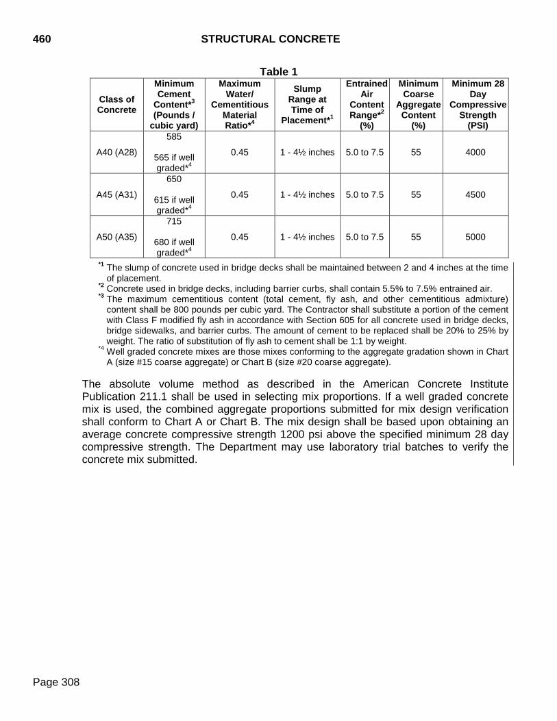
460 STRUCTURAL CONCRETE
Page 308
Table 1
Class of Concrete
Minimum Cement
Content*3 (Pounds /
cubic yard)
Maximum Water/
Cementitious Material Ratio*4
Slump Range at Time of
Placement*1
Entrained Air
Content Range*2
(%)
Minimum Coarse
Aggregate Content
(%)
Minimum 28 Day
Compressive Strength
(PSI)
A40 (A28)
585
565 if well graded*4
0.45 1 - 4½ inches 5.0 to 7.5 55 4000
A45 (A31)
650
615 if well graded*4
0.45 1 - 4½ inches 5.0 to 7.5 55 4500
A50 (A35)
715
680 if well graded*4
0.45 1 - 4½ inches 5.0 to 7.5 55 5000
*1 The slump of concrete used in bridge decks shall be maintained between 2 and 4 inches at the time
of placement. *2 Concrete used in bridge decks, including barrier curbs, shall contain 5.5% to 7.5% entrained air. *3 The maximum cementitious content (total cement, fly ash, and other cementitious admixture)
content shall be 800 pounds per cubic yard. The Contractor shall substitute a portion of the cement with Class F modified fly ash in accordance with Section 605 for all concrete used in bridge decks, bridge sidewalks, and barrier curbs. The amount of cement to be replaced shall be 20% to 25% by weight. The ratio of substitution of fly ash to cement shall be 1:1 by weight.
*4 Well graded concrete mixes are those mixes conforming to the aggregate gradation shown in Chart A (size #15 coarse aggregate) or Chart B (size #20 coarse aggregate).
The absolute volume method as described in the American Concrete Institute Publication 211.1 shall be used in selecting mix proportions. If a well graded concrete mix is used, the combined aggregate proportions submitted for mix design verification shall conform to Chart A or Chart B. The mix design shall be based upon obtaining an average concrete compressive strength 1200 psi above the specified minimum 28 day compressive strength. The Department may use laboratory trial batches to verify the concrete mix submitted.
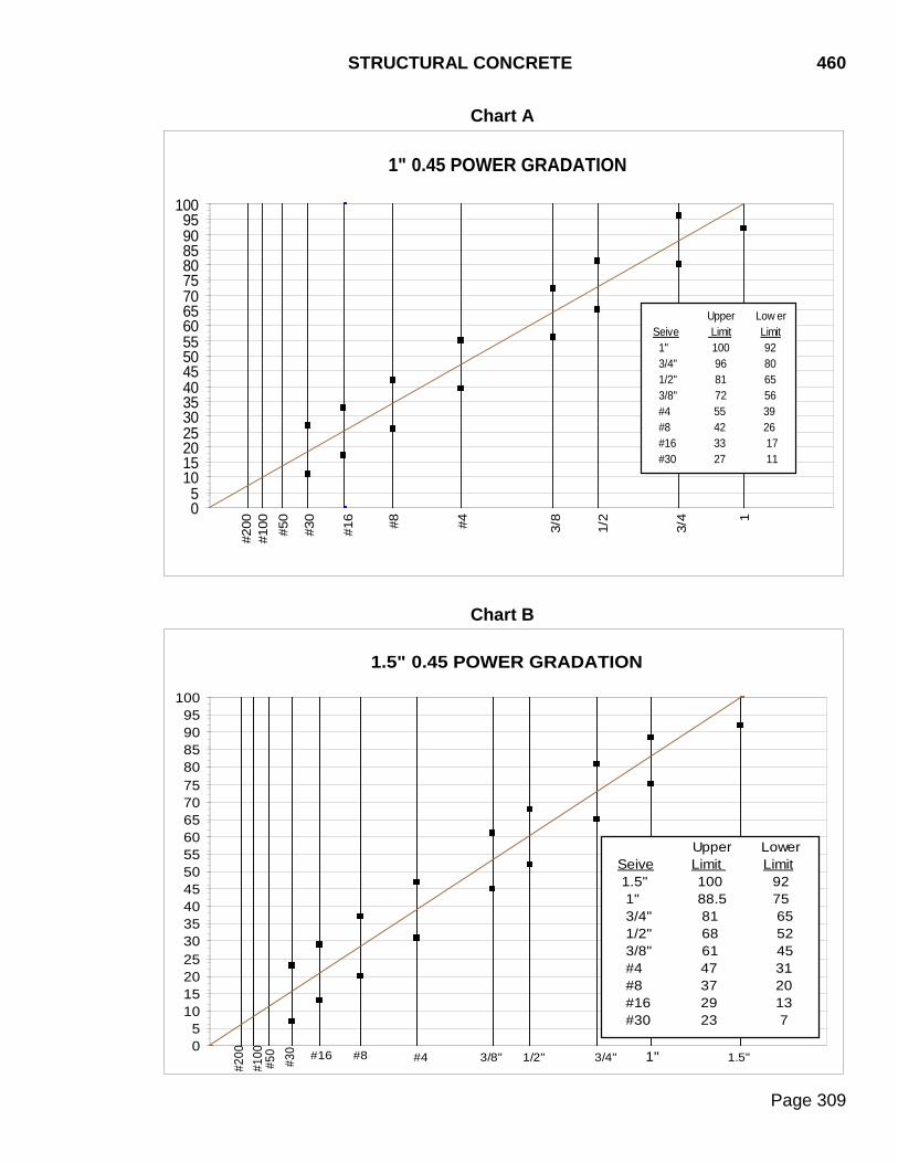
STRUCTURAL CONCRETE 460
Page 309
Chart A
Chart B
1" 0.45 POWER GRADATION
05
101520253035404550556065707580859095
100
#100
#200 #50
#30
#16 #8 #4 3/8
1/2
3/4 1
Upper Low er Seive Limit Limit 1" 100 92 3/4" 96 80 1/2" 81 65 3/8" 72 56 #4 55 39 #8 42 26 #16 33 17 #30 27 11
1.5" 0.45 POWER GRADATION
05
101520253035404550556065707580859095
100
#16 #8 #4 1/2" 1.5"1"3/4"#30
#50 3/8"
#200
#100
Upper Lower Seive Limit Limit 1.5" 100 92 1" 88.5 75 3/4" 81 65 1/2" 68 52 3/8" 61 45 #4 47 31 #8 37 20 #16 29 13 #30 23 7
460 STRUCTURAL CONCRETE
Page 310
1. Concrete Mix Design Performance: Satisfactory performance of the proposed
concrete mix design shall be verified by laboratory tests on trial batches. The trial batches must be performed by a testing facility approved by the Concrete Engineer. Trial batches shall be conducted in accordance with the American Concrete Institute Publication ACI 211.1, ACI 318, ASTM C192 and the following:
a. A minimum of three trial batches shall be performed. b. The slump of each trial batch shall be within ±3/4 inch of the maximum specified.
c. The air content of each trial batch shall be +0.5% to -1.0% of the maximum
specified. The results of each trial batch test shall be furnished by the Contractor to the Engineer at the time the proposed mix design is submitted. The as-batched results shall include the following: material weights, aggregate moistures, fresh concrete test results (slump, air content, unit weight, and mix temperature), water cementitious material ratios, aggregate gradations, compressive strengths, and aggregate qualities. In addition, aggregate supplier production test results shall be provided.
2. Alternate Concrete Mix Design: A concrete mix design previously used will be
considered in compliance with the mix design requirements provided all of the following conditions are met:
a. The concrete mix proportions are in accordance with Section 460.3 A. b. The mix design, including all material and admixtures, are identical to those
previously used and tested. c. The average 28 day compressive strength of 10 or more test results from an
approved testing facility is at least 1.34 standard deviations above the specified strength. These test results and associated batch tickets shall be submitted to the Engineer. No more than 1 in 10 compressive strength test results may be below specified strength.
d. The Contractor submits all supporting information for the mix design, including
but not limited to, fresh concrete tests and material properties.
B. Determination of 28 Day Compressive Strength and Acceptance Criteria: The Engineer will be responsible for the sampling, preparing, properly curing, and breaking of all concrete cylinders for concrete compressive strength in accordance with the Materials Manual. The 28 day compressive strength shall be determined in accordance with SD 420.
The 28 day compressive strength acceptance criteria shall be as follows:
STRUCTURAL CONCRETE 460
Page 311
1. Concrete Cylinder Testing: If the 28 day cylinder compressive strength is greater than or equal to the specified 28 day compressive strength, the quantity of concrete represented by the cylinder shall be accepted. If the 28 day cylinder compressive strength is less than the specified 28 day compressive strength, the backup cylinder shall be broken as soon as possible after breaking the 28 day cylinder. The compressive strength for the backup cylinder will be the strength at the time it was broken and will not be corrected back to a 28 day strength.
2. Backup Concrete Cylinder Testing: If the backup cylinder compressive strength is
greater than or equal to the specified 28 day compressive strength, the quantity of concrete represented by the cylinder shall be accepted.
If the backup cylinder compressive strength is less than the specified 28 day
compressive strength by no more than 500 psi, the Department’s Bridge Construction Engineer will determine if the unit is structurally adequate at the average compressive strength of the 28 day and the backup cylinder. If structurally adequate, the concrete will be allowed to remain in place and will be subject to price adjustment based on the average compressive strength of the two cylinders. If the analysis shows the average cylinder compressive strength is not structurally adequate, the concrete will be removed and replaced at the Contractor’s expense.
If the average compressive strength of the 28 day and the backup cylinder
compressive strength is more than 500 psi, below the specified 28 day compressive strength, the concrete represented by the cylinders shall be removed and replaced.
3. Suspect Test Results: If there is some reason to suspect that the compressive
strength test results are not valid due to a damaged concrete cylinder, malfunction of testing equipment, etc. or that the test results are not representative of the in place concrete, the Department may core the concrete represented by the cylinders. When cores are deemed necessary by the Department and are required at no fault of the Contractor, the Department will arrange for the additional testing and all costs will be borne by the Department. The coring and compressive testing shall be in accordance with the current edition of AASHTO T 24.
If the average core compressive strength is greater than or equal to the specified 28
day compressive strength, the quantity of concrete represented by the cylinders shall be accepted.
If the average core compressive strength is less than the specified 28 day
compressive strength by no more than 500 psi, the Department’s Bridge Construction Engineer will determine if the unit is structurally adequate at the lower compressive strength. If structurally adequate, the concrete will be allowed to remain in place and will be subject to price adjustment. If the analysis shows the average core compressive strength is not structurally adequate, the concrete will be removed and replaced at the Contractor’s expense.
460 STRUCTURAL CONCRETE
Page 312
If the average core compressive strength is more than 500 psi below the specified 28 day compressive strength, the concrete represented by the cylinders shall be removed and replaced.
4. Contractor Coring Option: If the Contractor disputes the accuracy of the 28 day
cylinder compressive strength, the Contractor has the option to core the concrete represented by the cylinders. Upon notification of a deviation from the specified compressive strength, the Contractor shall provide written notification of the intent to core the represented concrete within 5 calendar days. Coring shall be done in accordance with Section 460.3 B.5.
If the average core compressive strength is greater than or equal to the specified 28
day compressive strength, the quantity of concrete represented by the cylinder shall be accepted.
If the average core compressive strength is less than the specified 28 day
compressive strength by no more than 500 psi, the Department’s Bridge Construction Engineer will determine if the unit is structurally adequate at the lower compressive strength. If structurally adequate, the concrete will be allowed to remain in place and will be subject to price adjustment. If the analysis shows the average core compressive strength is not structurally adequate the concrete will be removed and replaced at the Contractor’s expense.
If the average core compressive strength is more than 500 psi below the specified
28 day compressive strength, the concrete represented by the cylinders shall be removed and replaced.
5. Coring & Compressive Testing: If the Contractor utilizes the option to core as
specified in Section 460.3 B.4, the Contractor shall arrange for an independent testing laboratory to perform the coring and compressive testing within 14 calendar days of notification of the failing compressive strength of the backup cylinder. The independent testing laboratory must be approved by the Department’s Concrete Engineer prior to starting the coring and compressive testing. The coring and compressive testing shall be in accordance with the current edition of AASHTO T 24.
The independent testing laboratory will take 3 cores of the area representing the cylinders in which the compressive strength is in question and test them for compressive strength. The coring and compressive testing shall be witnessed by the Department’s Region Materials Engineer. The Contractor will be responsible to locate the reinforcing steel prior to coring. It is critical that the coring operation avoids all reinforcing steel. The core holes shall be grouted with a grout that conforms to Section 460.2. The average compressive strength of 3 cores will be used for the determination of acceptance of concrete represented by each set of 28 day cylinders. One core’s compressive strength may be 15% below the specified strength if the average of the 3 core’s compressive strength is above the specified strength. ASTM E178
STRUCTURAL CONCRETE 460
Page 313
(Standard Practice for Dealing With Outlying Observations) will be used with the 10% significance level to deal with excessively high or low core strengths. If a core compressive strength is an outlier, then the set of cores will be averaged using the 2 remaining cores. The average compressive strength of the cores will prevail over all other compressive strength determination methods. If it is determined by the additional testing that the concrete is in compliance with the specified 28 day compressive strength, the Department will reimburse the Contractor for the cost of the coring and compressive testing. If it is determined by the additional testing that the 28 day compressive strength is less than that specified, all costs for the coring and compressive testing will be borne by the Contractor and the concrete shall be either accepted or rejected as per Section 460.3 B.4.
The following information shall be provided for each core taken:
a. Include DOT project number, county, & PCN. b. Core identification number & location of each core (representing cylinder number,
structure number, location of cores sketch, date concrete was cast, date cores taken, date cores tested)
c. Age of the concrete at the time of testing. d. Length & diameter of each core tested. e. Unit weight of each core. f. End preparation (capped or neoprene). g. Date of last calibration of the compression machine. h. What, if any, correction factor was used to compute the compressive strength. i. Actual calculations including load & cross-sectional area. j. Type of fracture as per ASTM C39. Note if the bond to the coarse aggregate is
not adequate due to cement adhesion. k. Any defects in either the core or the cap.
C. Equipment: Equipment shall be available in advance of the start of construction
operations to allow for thorough examination by the Engineer.
1. Batching Equipment: Batching equipment shall be automatic or a Department inspector shall be present during batching operations. The Contractor shall provide satisfactory means for obtaining material samples from the batching plant. Batching plant structures shall be leveled so the accuracy of the weighing mechanism is maintained. Hoppers shall fully discharge without jarring the scales. Clearances between scale parts, hoppers, and bin structure shall be maintained to avoid displacement of, or friction between, parts due to materials accumulations,
460 STRUCTURAL CONCRETE
Page 314
vibration, or other cause. Exposed fulcrums, clevises, and similar working parts shall be kept clean. To maintain accuracy, weighing hoppers and other parts which are affected by wind action shall be protected by shelters or wind breaks. The scale display shall be completely enclosed in weather proof cases and provided with glass opening to permit observation and reading. The equipment for weighing aggregates, cement, water, and admixtures shall be an integral part of the batching equipment. The scales/load cells shall be accurate within 0.5% at any point throughout the range of the scale/load cell. Graduations shall be not greater than 0.1% of the capacity of the scale/load cell. The scales/load cells shall be sensitive to the weight indicated by one graduation. The batching equipment shall operate within a delivery tolerance of 1.5% of the net weight for each aggregate weighed. The hopper inlet mechanism shall be interlocked against opening when the discharge gate is open. The hopper discharge mechanism shall be interlocked against opening while the hopper is being charged. The hopper discharge mechanism shall be interlocked against opening if any material in the hopper is either overweight or underweight by more than 1.5% of the specified weight. The cement batching equipment shall operate within a delivery tolerance of 1% of the net weight of the cement per batch. The cementitious material (cement and fly ash) batching equipment shall also operate within a delivery tolerance of 1% of the net weight of the total cementitious material per batch. Water may be measured by volume or weight. The measuring equipment shall operate within a delivery tolerance of 1% of the net weight or volume of water. When water is measured by volume, means for determining the accuracy of the measuring device shall be provided. Air-entraining or other admixtures may be measured by volume or by weight. The measuring equipment shall operate within a delivery tolerance of 3% of the net weight or volume per batch.
2. Computerized Batching Equipment: The following provisions shall apply to all Class A or Class M concrete batched by computerized batching equipment:
A printed, computer generated, ticket shall be automatically produced for each load of concrete batched. The printed computer ticket shall accompany each load of
STRUCTURAL CONCRETE 460
Page 315
concrete to the project and shall be presented to the Engineer prior to discharging the load at the project site unless the Engineer approves an alternate procedure. The printed ticket must contain the following minimum information:
Truck Number Date and Time batched Total volume of the load, in cubic yards DOT Mix Design Number Actual weight (mass) or volume of each component of the mix:
Coarse Aggregate Fine Aggregate Cement Fly ash Water (batch water) Admixtures
Air Entraining Admixtures Water Reducers Retarders Accelerators Others
% Moisture in Aggregate (either % free moisture or % total moisture) Maximum Water Allowed
(maximum water allowed = weight of mix design water - weight of free water) W/C ratio (as-batched)
The final W/C ratio, for acceptance, shall be calculated using the following formula and rounded to the nearest 0.01:
+
++=
material uscementitioary supplement of weight cement ofweight
wateradded of weight r batch wate of weight water free ofweight ratio W/C
% free moisture = % total moisture in aggregate - % absorption of aggregate weight of free water = % free moisture x weight of aggregate weight of batch water = total weight of water added to the batch either at the plant or in the
truck weight of added water = total weight of water added after batching process (typically added at
point of delivery)
The weight of free water shall be calculated for both the fine aggregate and the coarse aggregate. The above information must be automatically printed in such a manner that the Engineer may verify the mix adheres to the proportions specified by the design mix.
3. Mixing and Hauling Equipment: Mixers and agitators shall have attached in a
prominent place, a manufacturer plate or plates showing the various uses for which the equipment is designed and the capacity of the drum or container in terms of volume of mixed concrete.
460 STRUCTURAL CONCRETE
Page 316
The pick-up and throw-over blades in the drum shall be restored or replaced when any part or section is worn 3/4 inch or more below the original height of the manufacturer’s design. The Contractor shall maintain a copy of the manufacturer’s design, showing original dimensions and arrangement of blades. Mixers that have an accumulation of hard concrete or mortar shall not be used. Mixers, except truck mixers, shall be equipped with an approved timing device to track the total mixing time of the concrete batch.
Truck mixers shall be equipped with counters to record the number of revolutions of the drum or blades. The revolution counter on the truck mixers shall be set to zero as each new load is batched. Mixers shall be capable of combining the concrete ingredients into a thoroughly mixed and uniform mass and shall uniformly discharge the concrete. The hauling bodies of non-agitating equipment shall be smooth, mortar-tight metal containers equipped with gates and vibrators that will permit uniform control of the discharge of the concrete.
4. Forms and Falsework: Forms and falsework shall conform to Section 423.
D. Handling, Measuring, and Batching Materials: The separate aggregate components shall not become intermixed prior to being weighed and the weigh hopper or hoppers shall be charged so the batched weights are within the tolerances of 460.3 C.1
1. Cement shall be measured by the sack or by weight. When cement is weighed,
separate scales and hoppers shall be used with a device to indicate positively the complete discharge of the batch of cement into the mixing drum.
2. Admixtures shall be used in accordance with the manufacturer’s recommendations. When multiple types of admixtures are being used, the admixtures shall be individually dispensed. Compatibility of the admixtures shall be verified prior to use.
3. The amount of batch water and aggregates added to the mix shall be adjusted accordingly using the results of the most recent two hour moisture tests. If automatic moisture sensing equipment is used, the Engineer may allow the use of the automatic moisture sensing results to make adjustments.
E. Mixing Concrete: Concrete shall be mixed at a central stationary plant site or in truck
mixers.
Mixing and agitating speeds shall be as designated by the manufacturer of the equipment. Mixers shall not be charged in excess of the rated capacity. When a concrete batch is transported in a truck mixer or agitator and the batch is smaller than 60% of the rated capacity of the truck mixer or agitator, the following
STRUCTURAL CONCRETE 460
Page 317
percentage of additional cementitious material at the same proportions as listed on the mix design shall be added to the batch:
Percent of Rated Capacity
Additional Cementitious Material Required
40% to 60% 5% 20% to 39% 10% 10% to 19% 15% 0% to 9% 20%
The above provisions regarding additional cementitious material shall also apply to the mixing of small batches in central plants. Additional cementitious material will not be required when the small batch is mixed in a drum that is sufficiently coated with mortar to withstand the loss of cementitious material. Sufficient mortar coating, as determined by the Engineer, may include mortar coating the drum from a previously mixed batch during continuous mixing operations. Additional cementitious material will be required if more than 30 minutes has passed from the mixing of the previous batch, if the drum has been cleaned following the previous batch, or if the mortar coating the drum has been disturbed following the previous batch. 1. Central Plant Mixing: The batch shall be charged in the drum so a portion of the
mixing water enters in advance of the cement and aggregates. The flow of water shall be uniform and all water shall be in the drum by the end of the first 15 seconds of the mixing period. Concrete shall be mixed for a period of not less than one minute after all materials, are in the mixer. Concrete mixed less than the specified mixing time shall be discarded and disposed of.
2. Truck Mixing: Original mixing time for truck mixed concrete shall be not less than
70 or more than 100 revolutions of the drum at mixing speed after all ingredients, including water, are in the drum. Additional revolutions beyond 100 shall be done at agitating speed.
The mixing water shall be added at the time of batching. Additional water, cement, or admixtures may be added to the full load after completion of the original mixing, provided that slump, entrained air, and water cement specifications are adhered to. Addition of water, cement, or admixtures to partial loads is not allowed (partial loads of concrete are defined as loads that have been partially discharged). Admixtures shall be added in accordance with the manufacturer’s recommendations. When additional water, cement, or admixture is added, the batch shall be mixed an additional 30 revolutions at mixing speed. The Contractor shall provide means to accurately measure the amount of additional materials added.
460 STRUCTURAL CONCRETE
Page 318
3. Water/Cementitious Material Ratio: The water/cementitious material ratio of the concrete placed shall not exceed the maximum water/cementitious ratio established for the mix design.
F. Limitations of Mixing: Concrete shall be mixed in the quantities required for immediate use and shall be placed before initial set has occurred. Concrete in which initial set has begun prior to beginning placement shall be wasted at the Contractor's expense. Retempering of concrete after initial set has occurred will not be allowed.
Concrete shall not be mixed and placed unless the natural light is sufficient for finishing operations, or an adequate artificial lighting system is provided. Mixing water shall not be heated above 160°F. Aggregates shall not be heated above 100°F and shall be free of frozen lumps, ice, and snow.
G. Delivery Requirements: When concrete is continuously agitated in the hauling unit, the concrete shall be discharged within 90 minutes after the cement has been placed in contact with the aggregates and discharged and screeded within 105 minutes after the cement has been placed in contact with the aggregates. When the concrete temperature is 80°F or above, the time limitation shall be reduced to discharged within 45 minutes and discharged and screeded within 60 minutes.
When concrete is not continuously agitated in the hauling unit, the concrete shall be discharged within 45 minutes after the cement has been placed in contact with the aggregates and discharged and screeded within 60 minutes. When the concrete temperature is 80°F or above, the time limitation shall be reduced to discharged within 30 minutes and discharged and screeded within 45 minutes. The rate of delivery of concrete shall be uniform. The interval between batches shall not exceed 30 minutes. For delivery of concrete in remote locations where the preceding concrete delivery requirements will be difficult to meet, the Contractor may be allowed to use a set retarding admixture to control initial set when approved by the Engineer. When set retarding admixtures are allowed, the concrete delivery requirements may be adjusted with approval from the Department’s Concrete Engineer.
H. Construction Tolerances: Construction tolerances shall be in accordance with the latest edition of ACI 117, Standard Tolerances for Concrete Construction and Materials.
I. Pre-pour Inspection Requirements for Concrete Bridge Decks: Pre-pour
inspections will be conducted for all new concrete bridge decks. The Contractor shall advise the Engineer 24 hours in advance of the time when deck preparation will be complete and ready for inspection. The following items of work shall have been completed at the time of inspection:
1. Formwork: Formwork and decking shall be complete and joints made mortar tight.
STRUCTURAL CONCRETE 460
Page 319
2. Reinforcing Steel: Reinforcing steel shall be accurately placed in accordance with the tolerances of ACI 117, secured, and tied according to specifications.
3. Screed: Screed rails shall be set and adjusted for final grade.
4. Finishing Machine: Finishing machine shall be adjusted for crown slope and placed
upon the screed rails.
5. Safety: Necessary walkways and safety railing shall have been installed. 6. Inspections: A responsible Contractor employee shall be designated to accompany
the Engineer during the pre-pour inspection.
Following the pre-pour inspection, any corrective work required shall be completed during the normal work shift and shall not extend past the normal project work hours. Violation of this provision will be cause to postpone the scheduled deck placement.
J. Placing Concrete: The Contractor shall give sufficient notice before starting to place concrete to permit inspection of forms, reinforcing steel, and preparation for placing. Concrete shall not be placed without approval of the Engineer.
Placement of concrete on a frozen foundation will not be permitted. The surface temperature of forms, steel, and adjacent concrete which will come in contact with the concrete being placed shall be raised to a temperature above freezing prior to placement. The temperature of concrete immediately after placing shall not be less than 50°F or more than 90°F. The top limit for bridge deck concrete shall be 80°F except as indicated below. During periods of extreme and sustained hot weather it may become extremely difficult to maintain the 80°F maximum concrete temperature for bridge deck concrete. When such conditions exist the Engineer may authorize the maximum concrete temperature to be raised to 85°F provided the following conditions are met: 1. The coarse aggregate piles must be flushed with water for a minimum of 24 hours.
2. A minimum rate of pour of 40 cubic yards per hour, or as listed in the plans, must be
maintained.
3. Wet curing blankets and polyethylene sheeting must be placed as soon as possible after the pour.
4. If the ambient temperature is 80°F or less the concrete shall be cured as specified in
Section 460.3 M. Whenever the ambient temperature exceeds 80°F, a continuous fogging shall be applied from the time of initial strike off until the curing process specified in Section 460.3 M is in place. This continuous fogging shall be in addition to the curing process specified in Section 460.3 M.
460 STRUCTURAL CONCRETE
Page 320
Fogging equipment shall be capable of applying a fine mist, not a spray, under pressure through an atomizing nozzle. The fogging option will not be allowed when wind conditions preclude complete coverage.
Placement of concrete for bridge decks will not be permitted during the period from November 1 to April 1 (inclusive), without written authorization from the Engineer. Authorization will be given only if there is a distinct advantage to the Department. Barrier curbs will not be allowed to be placed with slipform paving equipment.
Before placing concrete, sawdust, chips, debris, and extraneous matter shall be removed from the interior of forms. Temporary struts, stays, and braces holding the forms in the correct shape and alignment, shall be removed when the fresh concrete has reached an elevation rendering their service unnecessary. These temporary members shall not be buried in the concrete.
The slope of chutes for concrete placement shall allow the concrete to flow slowly without segregation. The delivery point of the chute shall be as close as possible to the point of deposit. Chutes and spouts shall be kept clean and shall be thoroughly flushed with water before and after each run. The flush water shall be discharged outside the forms.
Free fall of concrete shall not exceed 5 feet. In thin walls or columns where the reinforcement prohibits the use of chutes the method of placement shall prevent objectionable separation of coarse aggregate.
The sequence of placing concrete, including the location of construction joints, shall be as specified. Concrete shall be placed in continuous horizontal layers. Each subsequent layer shall be placed before the preceding layer has attained its initial set.
The concrete shall be consolidated by vibrating internally, externally, or both without displacement of reinforcing or forms. The vibration shall be of sufficient duration and intensity to thoroughly consolidate the concrete without causing segregation; localized areas of grout; or damage to concrete, forms, and reinforcement.
Vibration shall not be applied directly to reinforcement which extends into sections or layers of concrete which are not plastic under vibration. Vibrators shall not be used to move concrete over distances or to transport concrete in the forms.
Accumulations of mortar splashed upon the reinforcing steel and the surfaces of forms shall be satisfactorily removed. Care shall be exercised not to injure or break the concrete to steel bond at and near the surface of the concrete while cleaning the reinforcing steel. Dried mortar chips and dust shall be removed and not left in the unset concrete.
K. Underwater Concrete Placement: Concrete placed under water shall be placed as per
Section 465.3 M.
STRUCTURAL CONCRETE 460
Page 321
L. Surface Finish: The surfaces of all structural concrete shall be worked during placing.
The working shall force all coarse aggregate from the surface and thoroughly work the mortar against the forms to produce a smooth finish relatively free of water, air pockets, and honeycombing.
As soon as the concrete has set in accordance with Section 460.3 O, the forms on all exposed surfaces shall be carefully removed and all depressions resulting from the removal of metal ties or other causes shall be carefully pointed with a mortar of sand and cement in the same proportions as the concrete being treated. All fins and rough corners on the surfaces shall be removed to present a neat and uniform appearance.
Additional finishing will be required as follows:
1. Rubbed, Brushed, and Commercial Texture Finishes: One of these three finishes
will be required for all railing, curbs, parapets, wing walls, and other surfaces not subject to wear which are visible to the traveling public unless otherwise designated in the plans. The selected finish shall be used throughout the entire structure, except the finish for the top and inside of the curb may be different than that used for the other parts of the structure. These finishes will not be required on surfaces which are not visible to the traveling public such as box culvert wing walls, box culvert parapets, bridge wing walls, and backsides of curbs on bridges, provided the forms result in a smooth unblemished surface.
a. Rubbed Finish: As soon as the pointing has set sufficiently, the surfaces to
receive a rubbed finish shall be thoroughly wetted with a brush and rubbed with a medium coarse carborundum stone or an abrasive of equal quality using a small amount of mortar on stone face. The rubbing shall be continued until all form marks and projections are removed, producing a relatively smooth clean surface free from pits or irregularities.
The final finish shall be obtained by rubbing with a fine carborundum stone or an abrasive of equal quality. This rubbing shall continue until the entire surface has a smooth texture and a uniform color.
b. Brushed Finish: This finish will be permitted only if it is accomplished within 12 hours of concrete placement. The forms shall be removed as soon as the concrete is able to stand firm without slumping. The surface shall be worked with a rubber float which may be dipped in a very wet three parts sand to one part cement grout mixture. Immediately after the surface is worked into a lather, a soft bristle brush shall be used to smooth the surface, leaving a fine grained, smooth but sanded texture. A "plastering" job resulting from the use of an excess of grout on the surface will not be permitted.
c. Commercial Texture Finish: The objective is to obtain a surface that is
reasonably smooth and uniform in texture and appearance. Repairing surface blemishes (bug holes, form lines, etc.) to prevent "show through" prior to application of the commercial texture finish is required. The commercial texture
460 STRUCTURAL CONCRETE
Page 322
finish shall be performed using an approved system from the Department’s Approved Products List. The Department’s Approved Products List contains two separate classes (Class A and Class B) for commercial texture finish. Unless otherwise specified on the plans, either Class A or Class B systems may be used. The Contractor is required to provide a copy of the manufacturer's recommendations to the Engineer prior to performing any commercial texture finish work.
Unless otherwise noted in the manufacturer's recommendations, commercial texture finish shall not be applied to any surface until the concrete is a minimum of 28 days old. The surfaces to receive commercial texture finish shall be abrasive blast cleaned to break the surface film, to remove all laitance and other foreign material, and to provide an absorptive surface. When allowed in the manufacturer's recommendations, pressure washing may be used to prepare the surface in lieu of abrasive blast cleaning. The commercial texture finish mixture shall be mixed in accordance with the method specified in the approved list for the system being used. The same materials and application method shall be used for all surfaces on any one structure. Commercial texture finish mixtures may be applied by a brushing, rolling, or by spraying, as per the manufacturer’s recommendations. The mixture shall cover the original surface with a one coat application. The one coat application shall not be too thick to cause runs, sags, or a plastered effect. After drying, the final surface shall be uniform in color and texture with no laps or breaks in continuity. The color of the system shall closely simulate the color of the original concrete, unless otherwise specified on the plans. The application of the commercial texture finish shall not be started until all other work that could damage the finish has been completed. The finishing operations shall be continuous until completion of the finish application on any one surface. Corrective work, at the Contractors expense, will be required on any surfaces which have not been satisfactorily finished or on finished surfaces that have been damaged during subsequent work. The repair work will include as much adjacent surface area as necessary to achieve a uniform appearance.
2. Special Surface Finish: Special surface finish will be required on the concrete
surfaces designated on the plans. The special surface finish shall be performed using an approved Class A or Class B system from the Department’s Approved Products List of materials/mixes for commercial texture finish.
Surface preparation shall be in accordance with the requirements of Section 460.3 L.1.c except that abrasive blast cleaning is required for all in place concrete surfaces. Pressure washing is not an acceptable method of surface preparation on these surfaces.
STRUCTURAL CONCRETE 460
Page 323
Mixing and application of the special surface finish shall be in accordance with Section 460.3 L.1.c for commercial texture finish.
3. Float Finish: Unformed surfaces, except bridge decks, approach slabs, and sleeper
slab top surfaces poured with the approach slab shall be given a float finish. After the concrete has been struck off, the surface shall be thoroughly worked and floated with a suitable floating tool. Before the finish has set, the surface cement film shall be removed with a fine brush in order to have a fine-grained, smooth but sanded texture.
4. Bridge Deck, Approach Slab, and Sleeper Slab Top Surface Poured with the
Approach Slab Finish: Immediately after the concrete has been placed and consolidated as required by Section 460.3 J, the surface shall be struck off and finished with an approved finishing machine. For bridge decks the finishing machine shall meet the following minimum requirements:
The finishing machine shall be a self-propelled rotating cylinder type, with one or more rotating steel cylinders and augers. The machine shall span the concrete placement width. The cylinders and augers shall spread and consolidate the concrete to the established profile by traversing the placement width, transverse to the roadway centerline. The machine shall be capable of forward and reverse motion under positive control, and be capable of raising all cylinders and augers to clear the surface when traveling in reverse. Any modifications to the factory product will require approval by the Engineer. The portion of the deck adjacent to curbs shall be neatly finished to a true surface with a wooden hand float.
Before the concrete has attained its initial set the concrete shall be given a final finish by transverse brooming or carpet drag to provide a surface microtexture.
The surface of concrete bridge decks,shall be given a transverse metal-tine finish. Tining depth and spacing shall be measured according to SD 418. The metal-tine finish shall provide a groove width of 1/8 inch and a groove depth of 6/32 inch ±2/32 inch. The spacing between the individual grooves shall be randomly spaced and shall vary between 5/8 inches to 1-5/8 inches with 50% of the spaces being 1 inch or less. The repeating random pattern on the tining device shall be avoided. Successive passes of the tining shall not overlap. The 12 inch width of the deck next to curb shall be left ungrooved. The surface of approach slabs and sleeper slab top surfaces poured with the approach slab shall be given a metal-tine finish in accordance with the metal-tine finish for bridge decks or a longitudinal metal-tine finish in accordance with Section 380.3 J.6.b.
After the concrete has hardened, the surface and joints shall be tested for smoothness in accordance with SD 417. The permissible longitudinal and transverse surface deviation shall be 1/8 inch in 10 feet. Any portion of the deck, approach slab, and sleeper slab top surface poured with the approach slab showing variation from the template of more than 1/8 inch shall be either ground to an elevation that will be within the permissible deviation or be accepted without corrective action and will be
460 STRUCTURAL CONCRETE
Page 324
subject to price reduction as determined by the Engineer under the provisions of Section 5.3.
The Contractor shall accomplish corrective grinding with specially prepared circular diamond blades mounted on a horizontal shaft. The Contractor shall daylight corrective grinding to the outside edge. The Contractor shall repair and replace joint sealant damaged by corrective grinding as directed by the Engineer and at no additional cost to the Department. The Contractor shall not leave ground areas smooth or polished. The Contractor shall ensure ground areas have a uniform texture equal in roughness to the surrounding unground concrete. The Contractor shall reestablish the tining with a mechanical tining machine in all areas where the corrective grinding exceeds 75 square feet. The Contractor shall remove and replace all joint sealant within the area where tining is replaced.
M. Curing Concrete: Concrete surface, except bridge decks, approach slabs, and sleeper
slab top surfaces poured with the approach slab shall be cured in accordance with Section 460.3 M.1. Bridge decks, approach slabs, and sleeper slab top surfaces poured with the approach slab shall be cured in accordance with Section 460.3 M.2. 1. Concrete surface, except bridge decks, approach slabs, and sleeper slab top
surfaces poured with the approach slab shall be cured as follows:
Concrete surfaces shall be kept continuously wet by ponding, spraying, or covering with materials that are kept continuously and thoroughly wet. Such materials shall consist of a double layer of a curing blanket or other materials, as approved by the Engineer, which does not discolor or damage the concrete. Forms shall be considered as adequate cover for curing the formed surface as long as the forms remain in place without loosening. Curing shall continue for not less than seven days after placing the concrete. Other precautions to ensure development of strength shall be taken as the Engineer may direct.
In lieu of the above method of curing, liquid membrane curing compound may be used. The compound shall be uniformly applied immediately after the final finishing operations are completed and the free water has left the surface. The curing compound may be applied in one or two applications in accordance with the directions of the manufacturer. If applied in two applications, the second shall be applied within 30 minutes of the first. Equipment, workmen, and materials will not be allowed on the surface for a minimum of seven days after application of the curing compound, unless the surface is adequately protected with an approved material. This protection shall not be applied for at least eight hours after application of the curing compound. If the membrane film is broken or damaged within the seven day curing period, the areas affected shall be given a duplicate treatment of the curing material, at the same application rate as the first treatment. Surfaces which are to receive a finish as per Section 460.3 L.1. and 460.3 L.2 shall not be treated with curing compound, curing shall be accomplished with a double
STRUCTURAL CONCRETE 460
Page 325
layer of curing blankets and polyethylene sheeting. Membrane curing compound will not be allowed on any surface to which concrete is to be bonded.
2. Bridge decks shall be cured in accordance with Section 460.3 M.2.a unless
otherwise specified in the plans.
a. Immediately after concrete finishing, a fog shall be applied to the exposed concrete surfaces until such time that wet curing blanket or other materials, as approved by the Engineer, is in place in such a way as to prevent drying of the concrete surface. Maintain the fogging to produce a “gloss to semi-gloss water sheen” on the concrete surface until the wet curing blanket is applied. The bridge deck surface shall not be treated with curing compound. Fogging equipment shall be capable of applying a fine fog mist in sufficient quantity to curb the effects of rapid evaporation of mixing water from the concrete resulting from wind, high temperature, or low humidity, or a combination of these factors. The fogging equipment shall be capable of being turned off and on as necessary, or as directed by the Engineer. Only equipment capable of producing a fog or mist shall be used. Moisture from the fog applicators under pressure shall not be applied directly upon the concrete and cannot accumulate on the surface in a quantity sufficient to cause a flow or wash the surface. Fog misting shall not be used to apply water to the surface of the concrete to facilitate lubrication for finishing purposes. Water on top of the fogged concrete surface shall not be worked into the surface of the concrete. Fogging equipment shall be such that the fog spray is produced from nozzles that atomize the droplets and are capable of keeping a large area damp without depositing excess water. Use high pressure equipment that generates at least 1200 psi at 2.2 gallons per minute or low pressure equipment having nozzles capable of supplying a maximum flow rate of 1.6 gallons per minute. Handheld weed sprayers are not allowed. Water shall not be allowed to drip, flow, or puddle on the concrete surface during fog misting. The Contractor shall demonstrate the fog mist system at the bridge deck prepour inspection to verify that sufficient volume and coverage will be attained. A fogging system shall not be used until approved by the Engineer. Apply fog spray upwind of the concrete placement during finishing, texturing, and until the concrete is covered by wet curing blanket. A single layer of wet curing blanket shall be placed as soon as possible and within a distance of 25 feet behind the finish machine. In the case the placement of the wet curing blanket within 25 feet is not practical, the Contractor shall keep the surface wet by fogging. In the event of a delay in concrete placement or finishing, the wet curing blanket shall be placed on as much of the exposed

460 STRUCTURAL CONCRETE
Page 326
concrete behind the finish machine as is practical. The curing blanket shall be pre-wetted by soaking in water for a minimum of 4 hours and then draining the soaked curing blanket such that the free water is removed prior to placement. If non-woven polypropylene geotextile is used, pre-wetting may be done immediately prior to placement. Caution shall be used when placing wet curing blanket so that no damage occurs to the surface. Placement of dry curing blanket and then wetting the curing blanket once it is in place is not allowed. The curing blanket shall be kept continuously wet by misting with water until such time that the concrete can support soaker hoses without causing deformation to the concrete. At that time, soaker hoses shall be placed on top of the curing blanket and the curing blanket and soaker hoses covered with polyethylene sheeting. In lieu of the preceding paragraph, the Contractor may immediately cover the wet curing blanket with polyethylene sheeting. Once the concrete can be walked on without damaging it, the Contractor shall then pull back the polyethylene sheeting and place the soaker hoses between the curing blanket and polyethylene sheeting. The curing blanket shall not be exposed for such duration that it dries prior to being recovered with the polyethylene sheeting. The soaker hoses must be placed and recovered within 24 hours of completion of the deck pour. Water shall be run through the soaker hoses periodically as required to keep the curing blanket continuously wet, but at a minimum of once per day. These wet cure procedures shall be continued for a period of 7 days after completion of the deck pour.
b. Bridge decks, when specified in the plans, approach slabs, and sleeper slab top surfaces poured with the approach slab shall be cured as follows: As soon as bridge deck, approach slab, and sleeper slab top surfaces poured with the approach slab concrete has received the final surface finish, linseed oil base emulsion curing compound shall be uniformly applied at the specified rate. This application is not a substitute for curing with curing blankets and polyethylene sheeting but is required for moisture retention until the curing blankets and polyethylene curing materials can be placed. The curing blankets and polyethylene sheeting curing materials shall be in place not later than 4 hours after completion of deck finishing. The concrete surfaces which are to have superimposed concrete placed upon or against them shall be protected from the curing compound and shall be cured with curing blankets and white polyethylene sheeting. All reinforcing steel shall be protected from the compound application.
3. Application of Curing Compound: Application of linseed oil base emulsion curing
compound shall conform to the following requirements:
a. Prior to and during application, the material shall be mixed to a uniform consistency without the use of air, violent agitation, or thinning.
STRUCTURAL CONCRETE 460
Page 327
b. The material shall be maintained above 50°F during application.
c. The material shall be applied with a spray applicator of sufficient capacity and with spray nozzles of proper size and design to provide a uniform application at the specified rate, immediately after the concrete has received the final finish.
d. The minimum application rate shall be as follows:
1) Carpet drag or broom finish - 1 gallon per 150 square feet.
2) Groove finish - 1 gallon per 125 square feet.
4. Curing Blankets and Polyethylene: Surfaces cured with curing blankets and
polyethylene sheeting shall be cured in the following manner:
a. The surface to be cured shall be entirely covered with a double layer of curing blankets. The curing blankets shall cover the entire surface with sufficient material beyond the periphery of the area to assure adequate curing of the edges. The curing blankets shall be thoroughly saturated with water and shall be placed with the wettest side down.
Combination burlap-polyethylene sheets may be substituted for one layer of curing blanket and the polyethylene film with the Engineer’s approval.
b. Immediately after placement, the curing blankets shall be entirely covered with
white polyethylene sheeting. Adjacent sheets shall be lapped at least 18 inches. The sheeting shall be placed and weighted down to ensure contact with the surface.
c. Curing shall be maintained for seven days. The curing blankets shall be kept
moist by periodic applications of water.
N. Protection of Concrete: The following provisions apply to all Class A concrete in addition to the requirements for curing contained in Section 460.3 M. Vibrations caused by any work activities that may be detrimental to the freshly placed concrete will not be allowed for at least 72 hours after placement or until the concrete has attained a minimum compressive strength of 1600 psi. If the Engineer suspects that construction activities may be causing excessive vibration, a 2 x 4 inch stake shall be driven solidly into the ground adjacent to the freshly placed concrete. A small container of water shall then be placed on top of the stake. If the water surface remains calm, the construction activity will be allowed to continue. When the water surface shows any movement, vibrations are reaching the freshly placed concrete and the construction activities shall be either stopped or altered such that vibrations at the freshly placed concrete are eliminated.
460 STRUCTURAL CONCRETE
Page 328
Enclosures for protection of concrete shall be capable of maintaining the temperature specified and permit free circulation of artificial heat. Open flame type heating units are prohibited.
Form insulation shall be bats of fiberglass, rockwool, balsam wool, or similar commercial insulation material. Insulation shall remain in place for the full protection period. The forms may be loosened slightly to control the temperature of the concrete below the maximum value specified.
The Contractor shall drill holes in the forms and provide thermometer wells 1/2 inch to 1 inch in depth at locations established by the Engineer, to determine the temperature of the concrete.
1. Concrete for sidewalks, curb and gutter, drop inlets, manholes, ditch checks, pipe
headwalls, sleeper slabs, approach slabs, pavement, etc. shall be maintained above 32°F until it has attained 1500 psi compressive strength.
2. Concrete for bridges, box culverts, retaining walls, anchor blocks, median barriers,
light and signal footings, and other structures shall be maintained at a temperature of 50°F or above for the first 72 hours after the concrete has been placed. The concrete shall be maintained at a temperature of 40°F or above for the next 48 hour period. If low temperatures are recorded during this protection period, one extra day of protection time above 40°F shall be added to the original five days of protection for each day that the minimum concrete temperature falls below the specified temperature.
If an additional bag of cement per cubic yard is used, or if high early strength cement is permitted, the concrete shall be maintained at a temperature of 60°F or above for 72 hours. If temperatures less than 60°F are recorded during this protection period, the protection time required shall revert back to that in the preceding paragraph with its provision for low temperatures also being applicable. Until one of the protection periods have been satisfied, cold weather protection shall continue, falsework shall remain in place, live loads shall not be applied, and the concrete temperature shall be maintained above 35°F.
At the end of the protection period, the concrete temperature shall not be permitted to fall more than 40°F in each subsequent 24 hour period.
The surface temperature of concrete protected by housing and heating or insulated forms shall not exceed 100°F during the protection period. It will be permissible to flood concrete with water to a minimum depth of 1 foot for 10 calendar days after the concrete is placed maintaining a water temperature which prevents freezing of the water in contact with the concrete.
O. Removal of Temporary Works and Construction of Superimposed Elements: Methods of removal of temporary works likely to cause overstressing of the concrete
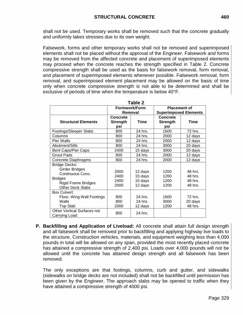
STRUCTURAL CONCRETE 460
Page 329
shall not be used. Temporary works shall be removed such that the concrete gradually and uniformly takes stresses due to its own weight.
Falsework, forms and other temporary works shall not be removed and superimposed elements shall not be placed without the approval of the Engineer. Falsework and forms may be removed from the affected concrete and placement of superimposed elements may proceed when the concrete reaches the strength specified in Table 2. Concrete compressive strength shall be used as the basis for falsework removal, form removal, and placement of superimposed elements whenever possible. Falsework removal, form removal, and superimposed element placement may be allowed on the basis of time only when concrete compressive strength is not able to be determined and shall be exclusive of periods of time when the temperature is below 40°F.
Table 2
Formwork/Form Removal
Placement of Superimposed Elements
Structural Elements Concrete Strength
psi Time
Concrete Strength
psi Time
Footings/Sleeper Slabs 800 24 hrs. 1600 72 hrs. Columns 800 24 hrs. 2000 12 days Pier Walls 800 24 hrs. 2000 12 days Abutment/Sills 800 24 hrs. 3000 20 days Bent Caps/Pier Caps 2400 15 days 3000 20 days Grout Pads 800 24 hrs. 2000 12 days Concrete Diaphragms 800 24 hrs. 2000 12 days Bridge Decks:
Girder Bridges Continuous Conc.
Bridges Rigid Frame Bridges Other Deck Slabs
2000 2400 2400 2000
12 days 15 days 15 days 12 days
1200 1200 1200 1200
48 hrs. 48 hrs. 48 hrs. 48 hrs.
Box Culvert: Floor, Wing Wall Footings Walls Top Slab
800 800 2000
24 hrs. 24 hrs. 12 days
1600 3000 1200
72 hrs. 20 days 48 hrs.
Other Vertical Surfaces not Carrying Load 800 24 hrs.
P. Backfilling and Application of Liveload: All concrete shall attain full design strength
and all falsework shall be removed prior to backfilling and applying highway live loads to the structure. Construction vehicles, materials, and equipment weighing less than 4,000 pounds in total will be allowed on any span, provided the most recently placed concrete has attained a compressive strength of 2,400 psi. Loads over 4,000 pounds will not be allowed until the concrete has attained design strength and all falsework has been removed.
The only exceptions are that footings, columns, curb and gutter, and sidewalks (sidewalks on bridge decks are not included) shall not be backfilled until permission has been given by the Engineer. The approach slabs may be opened to traffic when they have attained a compressive strength of 4000 psi.
460 STRUCTURAL CONCRETE
Page 330
Backfill material shall be placed in accordance with Section 420.3 G. Luminaires, sign poles, signals, and sign bridges shall not be installed on their footings until the concrete has reached full design strength.
Q. Joints: Surfaces of fresh concrete at horizontal joints shall be rough floated sufficiently to consolidate the surface. All construction joints shall be cleaned of surface laitance, curing compound, and other foreign materials prior to placing fresh concrete against the joint.
Drainage fabric shall be placed around construction joints on cast in place box culverts
in accordance with Section 422.
460.4 METHOD OF MEASUREMENT
Structural concrete will be measured in accordance with the neat line dimensions shown on the plans to the nearest 0.1 cubic yard, unless changes are ordered in writing. Deductions will not be made for the volume of concrete occupied by utility conduits, 6 inch or smaller drainage pipe, reinforcing steel, encased structural steel, pile heads, anchors, sleeves and encased grillage, or for volume of concrete displaced by weep holes, joints, drains and scuppers or for fillets, chamfers or scorings, 1 square inch or less in cross section. Concrete approach and sleeper slabs will be measured to the nearest 0.1 square yard. Concrete used for foundation seals will not be measured for payment. Commercial texture finish will not be measured for payment. The special surface finish will be measured along the neat line dimensions shown in the plans for the surfaces designated. The special surface finish will be computed to the nearest square foot. Concrete curing will not be measured.
460.5 BASIS OF PAYMENT
The accepted quantities of concrete will be paid for at the contract unit price per cubic yard.
Concrete approach and sleeper slabs will be paid for at the contract unit price per square yard.
Payment will be full compensation for labor, equipment, tools, materials and all other items of work required in furnishing, forming, placing, finishing, curing, protecting, and all other items incidental to the structural concrete.
Reinforcing and structural steel will be paid for separately.
STRUCTURAL CONCRETE 460
Page 331
When a bid item for concrete is provided, it will be considered full compensation for excavation necessary to construct the structure, unless a separate item is provided for such excavation. Commercial texture finish will be incidental to the contract unit price per cubic yard for structural concrete. Special surface finish will be paid for at the contract unit price per square foot.

460 STRUCTURAL CONCRETE
Page 332
THIS PAGE INTENTIONALLY LEFT BLANK
CONCRETE FOR INCIDENTAL CONSTRUCTION - CLASS M 462
Page 333
462.1 DESCRIPTION
This work consists of site preparation, form construction, and the furnishing, handling, placing, curing, and finishing of concrete for minor structures and incidental construction.
462.2 MATERIALS
Material shall conform to the following Sections:
A. Cement: Section 750. Type II cement shall be used, unless otherwise specified.
B. Fine Aggregate: Section 800.
C. Coarse Aggregate: Section 820.
D. Water: Section 790.
E. Admixtures: Sections 751 and 752.
F. Reinforcing Steel: Section 1010.
G. Curing Materials: Section 821.
H. Preformed Expansion Joint Filler: Section 860.
I. Joint Sealer: Section 870.
J. Fly Ash: Section753. K. Grout: Section 460.2 K.
462.3 CONSTRUCTION REQUIREMENTS
The supplier of Class M concrete will be required to furnish a written statement certifying the concrete furnished meets the applicable requirements of Section 462 for Class M concrete. With the exception of Section 462.3 A, the requirements of Section 462.3 shall not apply to Class M concrete produced at a commercial precast facility regularly producing other precast items under Section 560. Class M concrete produced at a commercial precast facility shall conform to Section 560 and Section 462.3 A. A. Concrete Quality and Proportion: The concrete specified in this section will be
designated as Class M6 concrete. 1. The following requirements shall apply for Class M6 concrete:
462 CONCRETE FOR INCIDENTAL CONSTRUCTION - CLASS M
Page 334
a. The concrete aggregate mixture shall contain a minimum of 50% coarse aggregate by weight.
b. The mixture shall contain at least 600 pounds of cement per cubic yard.
c. The minimum 28 day compressive strength shall be 4000 psi.
When Class M6 concrete is specified, the design mix for Class A40 concrete may be
substituted when approved.
2. Class M6 concrete shall conform to the following slump and entrained air requirements:
a. The slump at time of placement shall be maintained between 1 inch and 4½
inches. When high range water reducing admixtures (HRWRA) are used at a commercial precast facility regularly producing other precast items under Section 560, the slump at time of precast concrete placements shall be maintained between 4 inches and 8 inches.
b. The entrained air content for cast in place concrete shall be 6.5% plus 1.0%
minus 1.5%. The entrained air content for precast concrete, cast at a commercial precast facility regularly producing other precast items under Section 560, shall be 6.0% plus or minus 1.5%.
B. Forms: Wood and metal forms shall conform to 460.3 C.4.
C. Mixing Concrete: Concrete mixing shall conform to Section 460.3 E. D. Limitations of Mixing: Limitations of mixing shall conform to Section 460.3 F.
E. Delivery Requirements: Concrete delivery shall conform to Section 460.3 G.
F. Placing Concrete: Concrete placing shall conform to Section 460.3 J. G. Underwater Concrete Placement: Depositing concrete in water shall conform to
Section 465.3 M.
H. Surface Finish: Surface finish shall conform to Section 460.3 L. I. Curing Concrete: Curing concrete shall conform to Section 460.3 M. J. Protection of Concrete: Concrete shall be protected in accordance with Section 460.3
N. Concrete shall be maintained above 32°F until it has attained a compressive strength of 1500 psi.
K. Subsequent Construction: Removal of formwork, construction of superimposed
elements, backfilling, and application of liveloads shall conform to Section 460.3 O. and Section 460.3 P.
CONCRETE FOR INCIDENTAL CONSTRUCTION - CLASS M 462
Page 335
L. Joints: Joints shall conform to Section 460.3 Q.
462.4 METHOD OF MEASUREMENT
Class M concrete will be measured in accordance with neat line dimensions shown on the plans, unless changes are ordered during construction. Volumes will be computed to the nearest 0.1 cubic yard.
Deductions will not be made for concrete displaced by pipes or conduits less than 6 inches in diameter, reinforcing and structural steel, weep holes, joints, drains, and chamfers or fillets less than one square inch in cross section.
462.5 BASIS OF PAYMENT
The accepted quantity of Class M concrete will be paid for at contract unit price per cubic yard. Payment will be full compensation for labor, equipment, materials, and incidentals required for placing, finishing, and curing the concrete.

462 CONCRETE FOR INCIDENTAL CONSTRUCTION - CLASS M
Page 336
THIS PAGE INTENTIONALLY LEFT BLANK
CONTROLLED DENSITY FILL (New Section) 464
Page 337
464.1 DESCRIPTION This work consists of furnishing, handling, and placing controlled density fill.
464.2 MATERIALS
Materials shall conform to the following sections. A. Cement: Section 750. Type I, Type II, Type III, or Type V cement may be used, unless
otherwise specified. B. Fine Aggregate: Fine aggregate shall be a natural sand conforming to the following
gradation:
Sieve Size Percent Passing 3/8 inch 100 #200 0 – 10.0
C. Water: Section 790. D. Admixtures: Controlled low strength material (CLSM) performance additive (foaming
admixture) as listed on the Department’s approved products list. E. Fly Ash: Section 753, Class C.
464.3 CONSTRUCTION REQUIREMENT
A. General: Controlled density fill shall be a mortar material with a free flowing consistency.
B. Mix Design: The controlled density fill mix design shall be in accordance with Section 462, except as modified below:
Unless specified otherwise, the controlled density mix may conform to either of the two alternate mix designs. 1. Standard Mix Design:
Material Rate per Cubic Yard
Cement 100 pounds Fine Aggregate 2,600 pounds Water 60 gallons Fly Ash 300 pounds
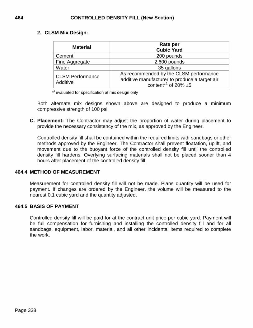
464 CONTROLLED DENSITY FILL (New Section)
Page 338
2. CLSM Mix Design:
Material Rate per Cubic Yard
Cement 200 pounds Fine Aggregate 2,600 pounds Water 35 gallons
CLSM Performance Additive
As recommended by the CLSM performance additive manufacturer to produce a target air
content*1 of 20% ±5
*1 evaluated for specification at mix design only Both alternate mix designs shown above are designed to produce a minimum compressive strength of 100 psi.
C. Placement: The Contractor may adjust the proportion of water during placement to provide the necessary consistency of the mix, as approved by the Engineer. Controlled density fill shall be contained within the required limits with sandbags or other methods approved by the Engineer. The Contractor shall prevent floatation, uplift, and movement due to the buoyant force of the controlled density fill until the controlled density fill hardens. Overlying surfacing materials shall not be placed sooner than 4 hours after placement of the controlled density fill.
464.4 METHOD OF MEASUREMENT
Measurement for controlled density fill will not be made. Plans quantity will be used for payment. If changes are ordered by the Engineer, the volume will be measured to the nearest 0.1 cubic yard and the quantity adjusted.
464.5 BASIS OF PAYMENT
Controlled density fill will be paid for at the contract unit price per cubic yard. Payment will be full compensation for furnishing and installing the controlled density fill and for all sandbags, equipment, labor, material, and all other incidental items required to complete the work.
DRILLED SHAFT CONSTRUCTION 465
Page 339
465.1 DESCRIPTION
This work consists of all labor, materials, equipment, and services required in the construction of drilled shafts.
465.2 MATERIALS
A. Concrete: Drilled shaft concrete shall conform to the requirements of Section 460, except where modified by this Section. At least 40 calendar days before constructing drilled shafts, the Contractor shall submit, to the Department’s Materials & Surfacing Central Laboratory, sufficient materials, including a water reducer, for a design mix. The concrete mix will be designed to produce a concrete having the following characteristics:
1. Minimum cement content of 780 pounds per cubic yard of Type II cement
conforming to Section 750;
2. Minimum 28 day compressive strength of 4500 psi;
3. Slump at time of placement shall be between 6 and 8 inches for concrete that is placed by the free-fall or tremie method. The slump at the time of placement shall be between 7 and 9 inches for concrete that is pumped through a tremie. In addition, the slump shall be maintained above 4 inches for 4 hours from the time of batching regardless of the placement method. Slump loss shall be tested in accordance with SD 423.
4. Entrained air content of 6.5% with an allowable tolerance of +1% to -1.5%.
5. The mix design shall establish a maximum water cementitious material ratio for the
concrete mix (never to exceed 0.44).
The use of a water reducer will be required to achieve the above properties. Water reducers conforming to AASHTO M 194 Type C (Accelerating) and Type E (Water-Reducing and Accelerating) will not be permitted.
B. Casing: Casing shall be smooth steel of sufficient thickness to withstand handling
stresses, concrete pressure, and surrounding earth and fluid pressures. The casing shall be of the diameter specified and shall have teeth at the bottom to facilitate proper seating of the casing into the plans specified formation.
C. Access Tubes for Crosshole Sonic Log (CSL) Testing: Access tubes shall be 1.5 to
2 inch I.D. steel pipe conforming to ASTM A53. The selected pipes must have a round diameter free of defects or obstructions, including any at the pipe joints, in order to permit a free, unobstructed passage of the source and receiver probes. The pipes must be watertight and free from corrosion with clean internal and external faces to ensure smooth passage of the probes and to secure a good bond between the concrete and tubes.
465 DRILLED SHAFT CONSTRUCTION
Page 340
The pipes shall each be fitted with a watertight shoe on the bottom and a removable cap on the top.
D. Grout: Grout for filling the access tubes at the completion of the CSL tests shall conform to the requirements of Section 460.2 or shall consist of Portland cement, water, and a water reducing admixture mixed in the following proportions:
Portland Cement Type I or II .................. 1 Sack (94 lbs.) Water ...................................................... 4.5 Gallons Maximum Water Reducing Admixture ..................... Manufacturer’s Recommendation Fly Ash (Optional) ................................... 20 Pounds Maximum
465.3 CONSTRUCTION REQUIREMENTS
A. Drilled Shaft Installation Plan: Not less than 30 calendar days before beginning drilled shaft construction, the Contractor shall submit an installation plan for approval to the Office of Bridge Design, through the Area Engineer. The installation plan shall provide the following information:
1. A list of all proposed equipment to be used and available on site including, but not
limited to, cranes, drill augers, pilot bits, bailing buckets, final cleaning equipment, dewatering pumps, tremies, concrete pumps, casing, etc. Include the casing diameter and wall thickness in the equipment list;
2. Details of the overall shaft construction sequence in each substructure unit or group
of drilled shafts;
3. A detailed explanation of how the casing is to be installed. It is required that a T-bar be on the project site such that the casing can be twisted into the specified formation to achieve as watertight of a seal as possible. Tamping or pounding the casing into the ground will not be allowed;
4. Details of shaft excavation methods to be used;
5. Methods to be used to clean the shaft excavation;
6. Details of reinforcement centering devices and their spacing;
7. Details and methods for supporting and lifting reinforcing steel cages;
8. Details of the tremie tube that is to be used in the event that a wet excavation is
encountered. Include all other details of concrete placement such as free fall (allowed only for shafts 36 inches in diameter or greater), pumping, etc. A tremie tube is required to be on the project site. Details for the disposal of contaminated concrete from a wet excavation shall also be included; and,

DRILLED SHAFT CONSTRUCTION 465
Page 341
9. The Contractor shall verify all existing ground and water elevations and establish the elevations of any work platforms, etc. that may be used. These elevations shall be included in the drilled shaft installation plan.
B. General Requirements: A drilled shaft preconstruction meeting is required to be held a
minimum of 5 working days prior to beginning drilled shaft construction. A representative from the bridge Contractor, drilled shaft subcontractor, concrete supplier, Area Office, and Office of Bridge Design is required to attend this meeting. The drilled shaft installation plan will be discussed at the meeting and the responsibilities of each of the parties involved clearly identified.
The Contractor shall perform the excavation for the shafts through the various types of materials that are encountered. The excavation shall be to the dimensions and elevations shown in the plans. Contractor methods and equipment shall be suitable for the intended purpose and materials encountered. All of the equipment listed in the drilled shaft installation plan shall be on the project site prior to the start of work. The following equipment is required to be available for use on the project site at all times during drilled shaft construction:
1. Tremie of sufficient length to reach the bottom of the drilled shaft;
2. T-bar for installing casing;
3. Cleanout bucket of the proper size;
4. Graduated measuring device to determine excavation and water depth;
5. Pilot bit capable of drilling through rock; and,
6. A pump of sufficient capacity to remove the displaced water during underwater
placement of concrete and for filling the excavation with water when required due to caving in or water bearing soils. Dewatering is a requirement prior to concrete placement by the free fall method.
Unless otherwise specified on the plans, the Contractor shall begin drilled shaft excavation using the dry construction method. The Contractor shall use the temporary casing construction method when specified on the plans or when caving soils or ground water is encountered during excavation that is begun by the dry construction method. The permanent casing construction method shall be used only when specified on the plans or approved by the Office of Bridge Design.
Upon completion of the excavation of a drilled shaft, a cleanout bucket shall be used to remove all loose material from the bottom of the shaft. After cleanout, the reinforcing steel shall immediately be installed and the concrete placed prior to start of excavation for another drilled shaft.
465 DRILLED SHAFT CONSTRUCTION
Page 342
For drilled shaft concrete pours of 18 cubic yards and less, the Contractor shall have all of the concrete necessary to complete the drilled shaft at the project site and tested prior to placing any concrete in the drilled shaft.
Vibrations caused by any work activities that may be detrimental to the freshly placed concrete will not be allowed for at least 72 hours after placement or until the concrete has attained a minimum compressive strength of 1600 psi. If the Engineer suspects that construction activities may be causing excessive vibration, a 2 x 4 inch stake shall be driven solidly into the ground adjacent to the freshly placed concrete. A small container of water shall then be placed on top of the stake. If the water surface remains calm, the construction activity will be allowed to continue. When the water surface shows any movement, vibrations are reaching the freshly placed concrete and the construction activities shall be either stopped or altered such that vibrations at the freshly placed concrete are eliminated.
C. Dry Construction Method: The dry construction method consists of drilling the shaft,
removing loose material from the excavation and placing the concrete in a relatively dry excavation. The Engineer must be able to inspect the sides and bottom of the excavation before placing the reinforcing steel cage and concrete. The dry construction method shall be approved by the Engineer when the shaft excavation has: a water accumulation rate of 3 inches or less per hour; the sides and bottom of the excavation remain stable without detrimental caving, sloughing or swelling; and loose material and water can be removed before inspection and concrete placement.
D. Temporary Casing Construction Method: The temporary casing construction method
shall be used when excavations, begun by the dry construction method, encounter water bearing or caving soil formations, or when specified on the plans. If, during dry drilling, the Contractor encounters caving or water bearing soils, the Contractor shall stop drilling and fill the hole with water to a point above the ground water elevation. If practical, a positive 10 foot head of water shall be maintained above the ground water elevation. When necessary, a temporary casing may be required to achieve this head. If caving soil is encountered, a sufficient head of water shall be maintained to stop the caving. Once the hole is filled with water, the excavation shall be advanced by drilling to a depth at which an impervious formation is reached. A sufficient head of water shall be maintained during the drilling operation. A temporary casing shall then be placed into the impervious formation by use of a T-bar and twisting the casing into the specified formation to produce a watertight seal at the bottom.
Other methods of seating the casing may be used with the Engineer's approval. The casing and the seal at the bottom of the casing shall be watertight. Water shall be pumped out of the temporary casing and the excavation continued using the dry construction method. During concrete placement, the casing shall be withdrawn. If a watertight seal cannot be achieved at the bottom of the casing, the shaft shall be drilled to the final elevation while keeping the hole full of water to maintain an adequate fluid head to control caving. Concrete shall then be placed using proper underwater concrete placement methods.
DRILLED SHAFT CONSTRUCTION 465
Page 343
1. If the Contractor elects to remove a casing and substitute a longer casing through caving soils, the excavation shall be backfilled before a new casing is installed. Other methods may be used to control the stability of the excavation and protect the integrity of the foundation soils when approved by the Engineer.
2. Temporary casing shall be removed before any of the drilled shaft concrete attains
initial set. Before the casing is withdrawn, the level of fresh concrete in the casing shall have sufficient head so all water trapped behind the casing is displaced upward without contaminating or displacing the concrete. When water seepage can not be stopped and water is required to maintain stability of the perimeter of the hole, the concrete shall be placed in the shaft using a tremie or pump. Simultaneously extract the casing and tremie, or pump, at a slow uniform rate. Maintain a sufficient head of concrete above the bottom of the casing to overcome the hydrostatic pressure outside the casing. The bottom of the tremie, or pump, shall always be embedded a minimum of 5 feet into the fresh concrete during the extraction.
3. Temporary casing shall be removed at the time of concrete placement. When a
casing becomes bound in the excavation, drilled shaft construction shall cease and the Engineer will immediately inform the Office of Bridge Design.
E. Permanent Casing Construction Method: The permanent casing construction method
shall be used only when specified on the plans or approved by the Office of Bridge Design. This method consists of placing a casing to a prescribed depth before excavation begins. If full penetration cannot be attained, the Engineer may require excavation of material within the embedded portion of the casing or excavation of a pilot hole ahead of the casing or both until the casing reaches the desired penetration. Over reaming to the outside diameter of the casing may be required before placing the casing, as approved by the Engineer.
A T-bar shall be used to twist the permanent casing into the specified formation to achieve a watertight seal at the bottom. Other methods of seating the permanent casing may be used with the Engineer's approval. The casing and the seal at the bottom of the casing shall be watertight. If the Contractor elects to remove a casing and substitute a longer casing through caving soils, the Engineer may require that the excavation be backfilled before a new casing is installed. Other methods may be used to control the stability of the excavation and protect the integrity of the foundation soils when approved by the Engineer. If, during dry drilling, the Contractor encounters caving or water bearing soils, the Contractor shall stop drilling and fill the hole with water to a point above the ground water elevation. If practical, a positive 10 foot head of water shall be maintained above the ground water elevation. If caving soil is encountered, a sufficient head of water shall be maintained to stop the caving. Once the hole is filled with water, the excavation shall be advanced by drilling. A sufficient head of water shall be maintained during the drilling operation.
465 DRILLED SHAFT CONSTRUCTION
Page 344
Upon completion of drilling, install reinforcing steel, and place concrete. After the concrete has attained the specified strength, the section of the casing between the plan shown cutoff elevation and the top shall be removed. When the cutoff elevation is not shown on the plans, the cutoff elevation is assumed to be flowline or ground line as appropriate. The casing shall be cutoff by use of a cutoff saw. Use of an oxyacetylene torch or other methods which produce high heat damaging the concrete will not be allowed. Casings may only be cutoff and removed when both of the following conditions are met:
1. The drilled shaft concrete has cured for 72 hours according to the specifications.
2. The drilled shaft concrete has attained 2500 psi minimum compressive strength.
F. Excavation and Drilling Equipment: Excavation and drilling equipment shall have
adequate capacity including power, torque, and downward force. The excavation and over reaming tools shall be of adequate design, size, and strength to perform the work shown in the plans and described in this specification. The excavation and drilling equipment shall be capable of excavating to the plans depth without the use of an extension bar. When the material encountered cannot be drilled using conventional earth augers and under reaming tools, the Contractor shall provide special drilling equipment including, but not limited to, rock core barrels, rock tools, air tools, blasting materials, and other equipment as necessary to excavate the shaft to the size and depth required. Approval by the Engineer is required before any excavation by blasting is conducted.
G. Reinforcing Steel Cage Construction and Placement: The reinforcing steel cage
(consisting of longitudinal bars, spirals or tie bars, cage stiffener bars, spacers, crosshole sonic log (CSL) access tubes, and centralizers) shall be completely assembled and placed as a unit into the excavated shaft. Placement of the reinforcing steel cage shall take place immediately after the shaft excavation is inspected and approved by the Engineer and before concrete placement.
The reinforcing steel cage shall be tied and supported in the shaft so the cage will remain within the specified tolerances. Welding of the reinforcing steel cage will not be allowed. Concrete centralizers or other approved noncorrosive centering devices shall be used within 1 foot of the bottom. Centralizers shall also be used at intervals not exceeding 5 feet along the length of the shaft. Each level of centralizers shall be rotated 45 degrees in the horizontal plane relative to the level below. Concrete centralizers shall be constructed of concrete equal in quality and durability to the concrete specified for the shaft. The concrete centralizers shall have the ends beveled to minimize the potential for catching on obstructions during reinforcing steel placement and they shall have a minimum of two tie wires cast in the concrete. Wrapping wires around the concrete centralizers to hold them in place is not an acceptable method of attachment. Any type of steel used as centralizers shall be epoxy coated. The reinforcing steel cage shall not be in contact with the bottom of the shaft.
The elevation of the top of the reinforcing steel cage shall be checked before and after the concrete is placed. If the reinforcing steel cage is not maintained within the specified
DRILLED SHAFT CONSTRUCTION 465
Page 345
tolerances, corrections to the cage support shall be made by the Contractor, as required by the Engineer. No additional shafts shall be constructed until the Contractor has modified the reinforcing steel cage support to prevent vertical movement, in a manner satisfactory to the Engineer.
H. Installation of Crosshole Sonic Log (CSL) Access Tubes: The Contractor shall install access tubes as detailed in the plans for CSL testing in all specified drilled shafts to permit access for the CLS test probes. The access tubes shall be evenly spaced and securely attached to the interior of the reinforcement cage of the shaft as shown in the plans. The tubes shall be as near to vertical and parallel as possible. Even moderate bending of the tubes will result in large regional variations of the data. The tubes shall extend from 3 inches above the bottom of the drilled shaft to at least 4 feet above the construction joint. Under no circumstances should the tubes be allowed to rest on the bottom of the drilled excavation. During placement of the reinforcement cage, care shall be exercised as to not damage the tubes.
After placement of the reinforcement cage, the tubes shall be filled with clean water as soon as possible and the tube tops capped to keep debris out. The tubes must be filled with water and capped either before the pouring of the concrete or no later than 4 hours after the pouring of the concrete, otherwise debonding of the access tubes from the concrete will occur resulting in data which indicates poor quality concrete. The Contractor shall ensure the tubes remain filled until grouting occurs. Care shall be taken during the removal of the caps from the pipes after installation so as not to apply excess torque, hammering, or other stresses which could break the bond between the tubes and the concrete. Upon completion of the CSL testing and acceptance of the drilled shaft by the Engineer, the water shall be removed from the access tubes and any other drilled holes. The access tubes and the holes shall then be completely filled with grout. The access tubes shall be filled using grout tubes that extend to the bottom of hole. The access tubes shall be cut off flush with the top of the drilled shaft.
I. CSL Testing: All equipment, testing, and reporting procedures shall be provided and performed in accordance with ASTM D6790 and the following.
1. Testing: The testing and analysis shall be performed by an independent testing
organization proposed by the Contractor and approved by the Engineer. The Contractor shall furnish and install access tubes as specified to accommodate the CSL testing.
The CSL testing shall be performed after the shaft concrete has cured at least 48 hours. Additional curing time prior to testing may be required if the shaft concrete contains admixtures, such as set retarding admixture or water reducing admixture. The additional curing time prior to testing required under these circumstances shall not be grounds for additional compensation or extension of time to the Contractor.
After placing the shaft concrete and before beginning CSL testing of a shaft, the Contractor shall inspect the access tubes. Each access tube that the test probe
465 DRILLED SHAFT CONSTRUCTION
Page 346
cannot pass through shall be replaced, at the Contractor's expense, with a 1.5 to 2 inch diameter hole cored through the concrete for the entire length of the shaft. Location of the core hole shall be determined by the CSL testing firm and shall not damage the shaft reinforcement. Descriptions of inclusions and voids in cored holes shall be logged and a copy of the log shall be submitted to the Engineer. Findings from cored holes shall be preserved, identified as to location, and made available for inspection by the Engineer.
2. Equipment: CSL equipment shall consist of the following components:
A digitizing card for conversion of analog CSL data to digital; A microprocessor based CSL system for recording, processing, analyzing, displaying and log printing of digitally converted CSL data; Ultrasonic source and receiver probes capable of logging 1.5 to 2 inch I.D. pipes; An ultrasonic voltage pulser to excite the source combined with a synchronized triggering system to prompt the recording system; A depth measuring device used to correlate records with depth; and, Appropriate filter/amplification and cable systems for CSL testing.
3. Procedure: For the CSL test, information on the shaft bottom and top elevations
and length, along with construction dates must be provided to the testing organization before or at the time of testing. Ultrasonic transmitter/receiver probes are then lowered to the bottom of a pair of access tubes. All slack is removed from the cable in order to assure accurate depth measurements. The two probes are then pulled simultaneously as to maintain a near horizontal ray path between them. Measurement shall be made at 0.2 foot intervals or less as the probes ascend the tube pairs. This process is repeated for all test paths along the outer perimeter as well as across the inner diagonals of the shaft. The data is analyzed and anomalies/defects characterized by longer travel times and lower signal amplitudes should be reported to the Engineer at the time of testing.
4. CSL Results: The CSL results shall be presented in report form. Digitized raw data
files shall also be submitted with the report. This report shall contain CSL logs and waterfall diagrams for each tube pair tested combined with an analysis of the first arrival time or compressional wave velocity and signal amplitude of the pulse versus depth. Any anomaly/defect zones shall be discussed in the report where appropriate.
The report shall identify and provide detailed discussion of each anomalous zone detected by the CSL. Anomalous zones are areas where velocity reduction exceeds 20% of the shaft average velocity. Within these zones collect and process additional data to construct three-dimensional color coded tomographic images with two-dimensional cross-sections between tubes within the anomalous zone.
DRILLED SHAFT CONSTRUCTION 465
Page 347
J. CSL Testing Organization and Personnel: At least 7 calendar days prior to beginning
shaft construction, the Contractor shall submit the name of the independent testing organization and the names of the personnel conducting the CSL tests to the Engineer for approval. The submittal shall include documentation that the qualifications specified below are satisfied. The independent testing organization and the testing personnel shall meet the following minimum qualifications:
1. The testing organization shall have performed CSL tests on a minimum of three
deep foundation projects in the last two years. 2. Personnel conducting the tests for the testing organization shall have a minimum of
one year experience in CSL testing and interpretation. K. Acceptance of CSL Tested Drilled Shafts: The acceptance of each drilled shaft shall
be the decision of the Engineer, based on the results of the CSL reports and other information about the shaft placement. De-watering and grouting of the access tubes and any subsequent work above the construction joint of the drilled shaft shall not be done until after the acceptance of each shaft. The Engineer will provide a response to the Contractor within 5 business days after receiving the test results and analysis submittal. Rejection of the shaft based on CSL shall require conclusive evidence that a defect exists in the shaft which will result in inadequate or unsafe performance under service loads. If the CSL records are complex or inconclusive the Engineer may require coring or excavation of the shaft to verify shaft conditions. If no defect is encountered, the state shall pay for all coring or excavation costs, including the grouting of all core holes.
In the case that any shaft is determined to be unacceptable, the contractor shall submit a plan for remedial action to the Engineer for approval. Any modifications to the foundation shafts and load transfer mechanisms caused by the remedial action will require calculations and working drawings stamped by a SD registered Professional Engineer for all foundation elements affected. All labor and materials required to perform remedial shaft action shall be provided at no cost to the Department and with no extension of the contract time.
L. Concrete Placement: The time limitations for drilled shaft concrete placement as specified in Section 460.3 G shall be waived except that the interval between batches shall not exceed 30 minutes. The drilled shaft concrete shall be placed immediately after the reinforcing steel cage is placed and shall be placed according to the requirements of this specification and all related specifications. When possible, drilled shaft concrete shall be placed the same working day in which the excavation is done. If it is anticipated that the excavation, reinforcing steel placement, and concrete placement cannot be completed before the end of the working day, the excavation shall not be started until the following day unless otherwise approved by the Engineer. It is required that drilled shaft concrete be placed within 24 hours of the excavation reaching the friction bedrock elevation specified in the plans. In the event that the 24 hour time limitation is exceeded, drilled shaft operations shall cease and the Office of Bridge Design shall be immediately notified.
465 DRILLED SHAFT CONSTRUCTION
Page 348
Concrete placement shall be continuous until the shaft is full and uncontaminated concrete flows out of the top of the shaft, as determined by the Engineer. The use of spud vibrators or other vibrating tools in the drilled shaft concrete will not be permitted.
The free fall method of concrete placement is allowed for shafts 36 inches in diameter or greater provided that all of the following conditions are met:
The water accumulation rate in the excavation is 3 inches or less per hour;
There is no caving or sloughing of the excavation;
The excavation is dewatered immediately prior to concrete placement such that there is no more than 3 inches of standing water in the bottom of the excavation; and,
The concrete placement is directed through a hopper with a drop tube such that the concrete fall is vertical down the center of the shaft and the concrete is not allowed to hit the sides of the shaft or the reinforcing steel cage.
M. Underwater Placement of Concrete:
1. Tremie: The tremie pipe shall be a minimum of 0.25 inch thick wall steel pipe, with a
minimum inside diameter of 7 3/4 inches. The tremie pipe shall be smooth and thoroughly cleaned of any hardened concrete, rust, and all other contaminants. The tremie pipe shall be marked to allow determination of depth to the mouth of the tremie. Joints between sections of tremie pipe shall be gasketed and bolted to be watertight under placement conditions. Instead of bolted joints, welded joints may be used if a smooth finish is maintained on the inside of the tremie pipe at the weld location.
A crane or other lifting device shall be available to remove the tremie from the water for resealing or horizontal relocation.
Placement of underwater concrete shall be a continuous operation. If an interruption of placement occurs, the interruption shall not exceed 30 minutes without removal of the tremie and restarting the concrete placement according to the paragraph below. An interruption in concrete placement shall not exceed the time for initial set of the concrete. If the concrete attains the initial set before the concrete placement is completed, concrete placement shall cease and the concrete in the shaft shall be rejected and removed from the shaft. Starting/Restarting of the concrete placement by tremie shall begin by sealing the bottom of the tremie with a watertight seal before placing the tremie into the water. The watertight seal shall prevent water from entering the tremie, yet will be dislodged when concrete flow is initiated. The empty tremie pipe shall be sufficiently heavy to be negatively buoyant when empty. The tremie pipe shall be sealed, lowered to the bottom of the shaft or embedded at least 5 feet into the concrete, and
DRILLED SHAFT CONSTRUCTION 465
Page 349
completely filled with concrete. Fill the tremie slowly to avoid entrapped air and bridging. When full, the tremie shall be slowly lifted 6 inches off the bottom to start concrete flow. The concrete supply shall be continuous until soundings indicate the tremie has the required embedment. After being dislodged, the sealing device shall either remain on the bottom or be retrieved by the Contractor. The mouth of the tremie shall always remain embedded in the fresh concrete a minimum of 5 feet unless the tremie is being completely removed from the water. At no time shall the concrete be allowed to fall through water. A tremie shall not be moved horizontally while concrete is flowing through it. To relocate a tremie, lift it from the water, reseal, relocate, and restart as required above. All vertical movements of the tremie shall be made slowly and shall be carefully controlled to prevent loss of seal. If loss of seal occurs, placement through that tremie shall be halted immediately. The tremie shall be removed, resealed, replaced, and restarted as directed above.
2. Concrete Pump: Concrete pumps can be used for underwater concrete placement
if surging of the pump line can be controlled to keep the pump line sufficiently embedded into the fresh concrete. If surging of the line cannot be controlled, a concrete pump shall not be used. The pump line shall be not less than 4 inches in diameter. The portion of the pump line that penetrates the deposited concrete shall be a rigid steel line (pipe). An approved plug shall be inserted into the pump line, near the pump, in such a way that there is fresh concrete against the plug, with no air or water between the plug and concrete. The plug shall be advanced down the pump line, using pressure from the concrete pump, to the bottom of the shaft. Placement shall begin with the pump line within 6 inches of the bottom of the shaft. After pumping begins, the pump line shall be kept within 6 inches of the bottom until soundings indicate that the pump line is embedded at least 5 feet into fresh concrete. The end of the pump line may be raised with the rising column of concrete as long as the end of the pump line remains embedded at least 5 feet into the concrete. At no time shall the concrete be allowed to fall through water. Placement of concrete shall be a continuous operation. Interruptions of placement shall not exceed 30 minutes or the time of initial set of the concrete whichever is shorter. If the time of initial set is exceeded, the concrete shall be rejected and removed from the shaft. If the pump line is allowed to come out of, or is removed from the concrete once placement has begun, placement though the pump line shall be restarted. A watertight seal shall be installed on the end of the pump line. The line shall then be filled with concrete before the pump line is lowered into the water. The pump line
465 DRILLED SHAFT CONSTRUCTION
Page 350
shall be filled in such a way as to eliminate air or water in the line. Once filled, the pump line shall be embedded a minimum of 5 feet into the concrete and pumping resumed. The sealing device shall be retrieved by the contractor after pumping has been restarted.
N. Construction Tolerances: The following tolerances apply to drilled shafts:
The drilled shaft shall be within one twelfth of the shaft diameter or 3 inches, whichever is less, of the plan shown horizontal position, at the plan elevation of the top of the shaft.
The bottom of the shaft shall be drilled to the plan shown elevation, within a tolerance of plus or minus 6 inches.
The vertical alignment of the shaft excavation shall not vary from the plan alignment by more than 1/4 inch per 1 foot of depth or 3 inches of length or, whichever is less.
After all concrete is placed, the top of the reinforcing steel cage shall be no more than 6 inches above nor more than 3 inches below plan position. The diameter of the completed shaft shall be the plan diameter with a tolerance of minus 0 inch, plus 2 inches. The top of the shaft shall be built to plan elevation with a tolerance of plus or minus 1 inch. The plan shown elevation of the top of shaft shall not be changed without prior permission from the Office of Bridge Design. Excavation equipment and methods shall be designed so the completed shaft excavation will have a relatively flat bottom.
465.4 METHOD OF MEASUREMENT
A. Class A45 Concrete, Drilled Shaft: The plan quantity shall be the quantity paid for unless a change is ordered in writing. If a change is ordered, measurement will be according to neat line dimensions specified in the change and quantities computed to the nearest 0.1 cubic yard.
B. Drilled Shaft Excavation: The plan quantity shall be the quantity paid for unless a
change is ordered in writing. If a change is ordered, measurement will be according to the neat line dimensions specified in the change and quantities computed to the nearest 0.1 cubic yard.
C. Permanent Casing: The length of casing from the plan shown cutoff elevation to the
bottom of the casing unless otherwise specified in the plans. Permanent Casing shall be measured to the nearest 0.1 linear foot, for each specified size of casing.
D. Crosshole Sonic Log (CSL) Test: will be measured by the number of shafts tested.
CSL testing will only be measured once per shaft tested.
DRILLED SHAFT CONSTRUCTION 465
Page 351
465.5 BASIS OF PAYMENT
A. Class A45 Concrete Drilled Shaft: The accepted quantities of concrete will be paid for at the contract unit price per cubic yard. Payment will be full compensation for labor, equipment, tools, materials, and all incidentals required. All costs for furnishing, installing, cutting off, and grouting the CSL access tubes will be incidental to the unit price bid for Class A45 concrete drilled shaft. Payment will be for plan quantity regardless of the amount placed. If a change is ordered, payment will be for the changed quantity at the contract unit price.
B. Drilled Shaft Excavation: The accepted quantities of excavation shall be paid for at the
contract unit price per cubic yard. Payment will be full compensation for labor, equipment, tools, materials, and all incidentals required, including blasting equipment and temporary casings. Payment will be for plan quantity regardless of the amount placed. If a change is ordered, payment will be for the changed quantity at the contract unit price
C. Permanent Casing: The accepted quantities of casing will be paid for at the contract unit price per linear foot, for each specified size. Payment will be full compensation for labor, equipment, tools, materials, and all incidentals required.
D. Crosshole Sonic Log (CSL) Test: The accepted quantity of cross sonic log tests will
be paid at the contract unit price per each test. Payment will be full compensation for all labor, equipment, tools, materials, services, and incidentals required to perform the tests and analyze the results. Payment will be made only once per shaft tested.

465 DRILLED SHAFT CONSTRUCTION
Page 352
THIS PAGE INTENTIONALLY LEFT BLANK
RAILING 470
Page 353
470.1 DESCRIPTION This work consists of fabricating and constructing steel railings.
470.2 MATERIALS
Materials shall conform to the following sections: A. Structural Steel: Structural steel shall conform to Section 970. Unless otherwise
specified on the plans, structural steel for railing shall conform to ASTM A709/A709M, Grade 36 except that hollow structural section members shall conform to ASTM A500, Grade B.
B. Anchor Bolts: Anchor bolts shall be as specified in the plans and shall conform to
Section 972.
C. Paint: Paint shall conform to Section 411. 470.3 CONSTRUCTION REQUIREMENTS
Railing shall be fabricated and erected in accordance with Section 410.3 and the following: Unless otherwise specified in the plans, the Contractor shall submit shop plans in accordance with the following: Prior to fabrication, the Contractor shall submit shop plans to the Department for the Department’s review and approval. The Contractor shall send an email with the shop plans attached as a PDF to the Project Engineer and Office of Bridge Design. Upon request, the Project Engineer will provide the Contractor the appropriate email addresses. The Contractor shall not begin fabrication prior to the Department’s review and final approval of shop plans. Within 14 calendar days of receiving the initial shop plans, the Office of Bridge Design will send a response to the Contractor and submitter with the Department’s final approval or one reviewed copy of the shop plans with changes to the design marked. The Contractor will make the necessary changes, if any, to the shop plans. The Contractor will then send the Project Engineer and the Office of Bridge Design an email with the final shop plans as a PDF for distribution. Railing shall be constructed in accordance with the details shown and the shop plans and shall be adjusted prior to bolting or welding the connections to ensure proper alignment at joints and throughout the railing length. Rail posts shall be built vertical. Shop and field welding, and welding inspection shall conform to the requirements in the latest edition of ANSI/AWS D1.1 or 1.5, whichever is applicable, Structural Welding Code. Welders shall be qualified in accordance with Section 410.3 D. The painting of railing shall conform to Section 411.
470 RAILING
Page 354
470.4 METHOD OF MEASUREMENT
Measurement for railing will not be made. Plans quantity will be used for payment. 470.5 BASIS OF PAYMENT
The accepted quantities of railing will be paid for as detailed on the plans and, unless otherwise specified on the plans, shall include the cost of structural steel, anchor bolts, painting, galvanizing, welding, weld inspection, labor, equipment and all other items incidental to fabricating and installing the railing.
REINFORCING STEEL 480
Page 355
480.1 DESCRIPTION
This work consists of furnishing and placing steel of the specified size and type, as reinforcement in concrete.
480.2 MATERIAL
Reinforcement shall conform to Section 1010. Reinforcement shall be furnished in the full lengths indicated on the plans.
480.3 CONSTRUCTION REQUIREMENTS
A. Protection of Material: Steel reinforcement shall be protected from damage and when placed in the work, steel reinforcement shall be free from dirt, detrimental scale, paint, oil, and other foreign substance. Steel reinforcement shall be stored above ground on platforms, skids, or other supports.
When epoxy coated steel reinforcement is specified, the following requirements also apply:
1. In order to protect the coated reinforcement from damage, the Contractor shall use
padded or non-metallic slings or straps to load, unload, or move epoxy coated reinforcement.
2. Bundled bars shall be handled in a manner as to prevent excessive sagging of the
bars so as not to damage the epoxy coating.
3. To prevent damage to the epoxy coating, care shall be taken during placement of epoxy coated reinforcement to ensure the bars are not dropped or dragged.
4. Damaged areas shall be repaired by removing all rust and contaminants from the
damaged area and applying an epoxy coating to the damaged area. The touch up epoxy coating material shall be inert in concrete and compatible with the original epoxy coating and the reinforcing steel. This coating material shall be epoxy coating touch up material supplied by an epoxy coating manufacturer who supplies coating material for new epoxy coated reinforcing steel. Touch up epoxy coatings from spray cans will not be permitted. The touch up epoxy coating shall be allowed to cure for a minimum of 24 hours or as per the manufacturer's recommendations, whichever is more stringent, before concrete is placed.
5. Epoxy coated reinforcing steel shall be covered with a heavy duty waterproof
opaque covering to protect the epoxy coating from dirt and debris and from the effects of ultraviolet rays if the reinforcing steel will be stored for more than 30 calendar days.
B. Bending: Reinforcement shall be bent to the shapes specified. Bending and bundling
shall conform to the standard practice currently specified by the Concrete Reinforcing Steel Institute.
480 REINFORCING STEEL
Page 356
C. Placing and Fastening: Reinforcing steel shall be accurately placed in accordance
with the tolerances of ACI 117 and firmly held in the positions specified using steel chairs or other approved methods. Bars shall be tied at all intersections (100%) when spacing is 1 foot or more in all directions (longitudinal, vertical, and horizontal), otherwise a minimum of every other intersection (50%) shall be tied.
1. General: Distances from the forms shall be maintained by stays, blocks, ties, chairs,
or hangers. Devices for holding reinforcement from contact with the forms shall be of approved shape and dimensions. Layers of bars shall be separated by approved metal devices. The use of pebbles, stone, brick, metal pipe, and wooden blocks will not be permitted.
Wire bar supports, such as ferrous metal chairs and bolsters, shall conform to
industry practice as described in the manual of Standard Practice of the Concrete Reinforcing Steel Institute. Chairs or bolsters which bear against the forms for exposed surfaces shall be either Class 1 - Maximum Protection (plastic protected) or Class 2 - Moderate Protection, Type B (stainless steel tipped) for which the stainless steel conforms to ASTM A493, Type 430. Chairs or bolsters which are earth bearing shall be Class 3 - No Protection (bright basic bar supports). For epoxy coated reinforcement, all wire bar supports and bar clips shall be plastic or epoxy coated.
Chair spacing shall not exceed 3 feet 6 inches in either direction. The Engineer may
require a closer chair spacing for mat rigidity. Plastic chairs shall not be used. Tie wires shall be black-annealed 16 1/2 gauge or heavier. Ties shall be plastic
coated when used in conjunction with epoxy coated reinforcing steel.
Welding of reinforcing steel shall not be allowed without written approval of the Bridge Construction Engineer. The request for approval shall list the bars to be welded, welding procedure, type of electrode, joint detail, and mill certificate of the reinforcing steel to be welded.
Reinforcement shall be inspected and approved, before the placing of concrete
begins. The placing of any reinforcement except mesh during the process of placing the concrete will not be permitted. Concrete placed in violation of this provision may be rejected and ordered removed.
2. Structures: When placing bridge deck and box culvert reinforcement either slab
bolster (SB) or beam bolster (BB) bar supports shall be used between the mats or reinforcement and the form work. Either slab bolster upper (SBU) or beam bolster upper (BBU) bar supports shall be used between mats of reinforcing steel. Individual high chair (HC) bar supports shall not be used.
On girder bridges either slab bolster upper (SBU) or beam bolster upper (BBU) bar supports shall be used between mats of reinforcement and placed transverse to the girders. Slab bolsters (SB) or beam bolsters (BB) shall be used under the bottom mat placed parallel to the girders.
REINFORCING STEEL 480
Page 357
The top mat of bridge slab and box culvert reinforcement shall be tied down with 16 1/2 gauge diameter (minimum) tie wires or other approved devices. It will not be permissible to tack weld reinforcement. On girder bridges, ties shall be used along each line of beams at longitudinal intervals not to exceed 8 feet. The ties shall be secured to the shear transfer devices protruding from the top of the beam. Where shear transfer devices are not available, the ties may be secured to the bottom mat of slab reinforcing steel. Other types of bridges and box culverts the top mat of reinforcement shall be tied down at a maximum of 12 foot longitudinal and transverse intervals with the ties secured to either the forms or bottom mat of slab reinforcing steel.
3. Continuous Reinforced Concrete Pavement: On continuous reinforced concrete pavement, the Contractor shall use continuous high chair (CHCP) and beam bolsters (BBP) with earth-bearing bases or sand plates (P) or an approved alternate. Individual high chair (HC) bar supports shall not be used.
D. Mechanical Bar Splices
Mechanical bar splices shall only be used when specified in the plans or approved by the Engineer. The model of mechanical bar splice to be used shall be submitted to the Office of Bridge Design through the proper channels for approval. The mechanical connection shall develop 125% of the specified yield strength of a Grade 60 bar. The Contractor shall obtain from the manufacturer and submit to the Engineer certification indicating the mechanical bar splice is capable of developing 125% of the specified yield strength of a Grade 60 bar. The bar lengths shown in the plans are the lengths of the bars neglecting the mechanical bar splice. When mechanical bar splices are used to splice epoxy coated bars, the mechanical bar splices shall be epoxy coated by the manufacturer or made of an approved corrosion resistant material. Coating the mechanical bar splice with epoxy touch-up is not an approved method for this situation.
480.4 METHOD OF MEASUREMENT
Reinforcing Steel will be measured by the pound, based on the theoretical weight complete in place. The weights calculated shall be based upon the following table:
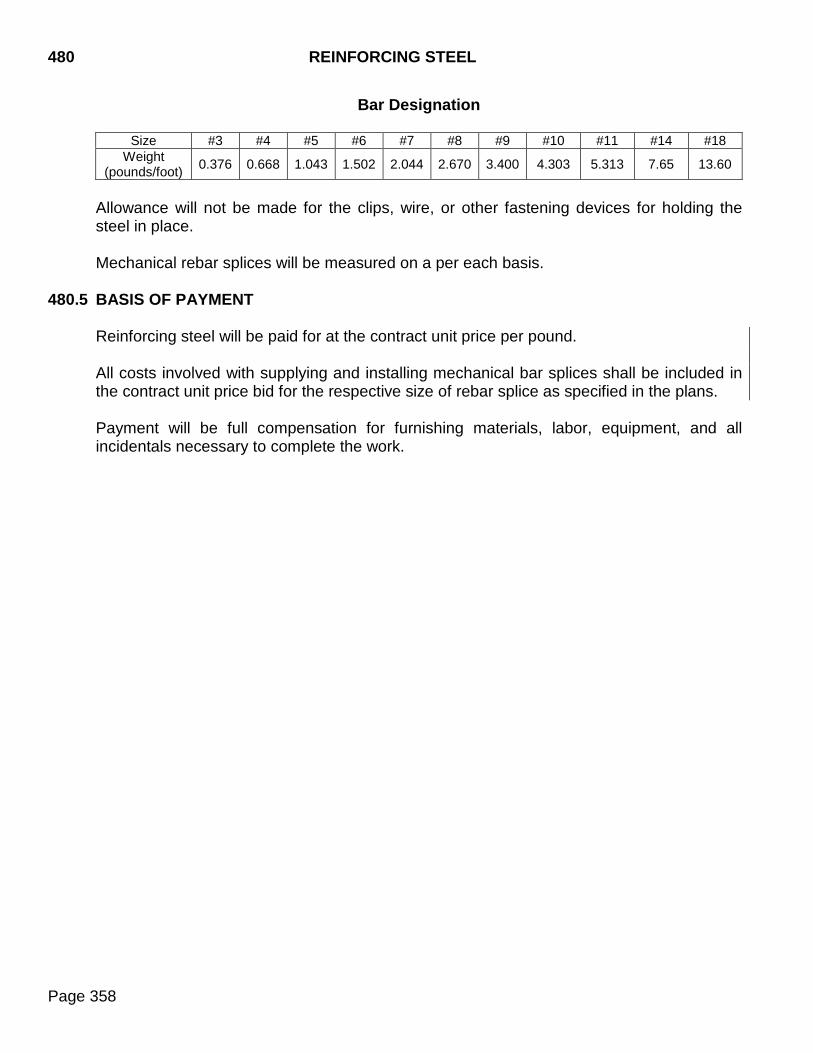
480 REINFORCING STEEL
Page 358
Bar Designation
Size #3 #4 #5 #6 #7 #8 #9 #10 #11 #14 #18 Weight
(pounds/foot) 0.376 0.668 1.043 1.502 2.044 2.670 3.400 4.303 5.313 7.65 13.60
Allowance will not be made for the clips, wire, or other fastening devices for holding the steel in place. Mechanical rebar splices will be measured on a per each basis.
480.5 BASIS OF PAYMENT
Reinforcing steel will be paid for at the contract unit price per pound. All costs involved with supplying and installing mechanical bar splices shall be included in the contract unit price bid for the respective size of rebar splice as specified in the plans. Payment will be full compensation for furnishing materials, labor, equipment, and all incidentals necessary to complete the work.
BRIDGE DECK POLYMER CHIP SEAL 491
Page 359
491.1 DESCRIPTION
This work consists of preparation of the plans specified existing bridge deck surface and furnishing and placing two coats of a polymer chip seal on the prepared bridge deck surface.
491.2 MATERIALS Materials shall conform to the following Sections: A. Concrete Patching Material: Concrete patching material shall be packaged, dry, rapid-
hardening cementitious mortar or concrete materials conforming to the requirements of ASTM C 928, Type R-3 and shall contain a bonding agent and shall not contain any chlorides, magnesium, or phosphates.
B. Water: Section 790 C. Polymer: Section 805 D. Cover Aggregate: Section 805
491.3 CONSTRUCTION REQUIREMENTS
A. Surface Preparation
1. Removal and Replacement of Loose and Delaminated Concrete:
a. Concrete Removal Classification: Concrete removal shall be divided into one of the following two classes:
1) Concrete Removal, Class A: Concrete removal, Class A shall consist of the
removal of delaminated and visibly loose concrete and any bituminous patches (when present) from the top of existing bridge deck down to a depth no deeper than the top of the top bar in the top mat of bridge deck reinforcing steel. Unintentional concrete removal below the top of the top bar in the top mat of bridge deck reinforcing steel during the concrete removal, Class A process will be considered a part of concrete removal, Class A. When grinding is specified, the concrete removal, Class A shall be done after the bridge deck has been ground.
2) Concrete Removal, Class B: Concrete removal, Class B areas shall be
determined by the Engineer after completion of the concrete removal, Class A has been accomplished. Concrete removal, Class B shall consist of the removal of delaminated and visibly loose concrete that exists below the bottom limits of the concrete removal, Class A (below the top of the top bar in the top mat of bridge deck reinforcing steel).
491 BRIDGE DECK POLYMER CHIP SEAL
Page 360
b. Concrete Removal: Concrete removal shall be accomplished by jackhammers and chipping hammers or other methods as approved by the Engineer. Jackhammers and chipping hammers shall be used as follows:
1) Jackhammers heavier than 30 pounds will not be permitted. 2) Chipping hammers heavier than 15 pounds will not be permitted for removing
concrete below the top of the top mat of reinforcing steel. 3) Jackhammers and chipping hammers shall not be operated at an angle in
excess of 45 degrees measured from the surface of the concrete. 4) Extreme care shall be taken when using jackhammers and chipping hammers
to assure that existing reinforcing steel is not damaged or debonded from the sound concrete.
Removal shall begin near the center of the loose or delaminated concrete and shall progress outwardly until the loose or delaminated concrete is removed and sound concrete is encountered such that the amount of concrete removal is minimized. The edges of removed concrete shall be defined with a 3/4 inch deep saw cut where practical, as approved by the Engineer. If saw cutting is not practical, the use of jackhammers or chipping hammers may be required around the edges of the removal area to attain satisfactory results. Care shall be taken during concrete removal to not nick, gouge, or in any other way damage the in place reinforcing steel. Any inadvertent damage to the in place reinforcing steel shall be brought to the attention of the Department’s Bridge Construction Engineer and shall be repaired by the Contractor as directed by the Engineer at no additional cost to the Department.
c. Concrete Replacement: Upon completion of the concrete removal and immediately prior to placing any concrete patching material into the concrete removal areas, the removal areas shall be thoroughly cleaned of loose and foreign material by abrasive blasting. The surface profile of the area to receive the concrete patching material shall be in accordance with the manufacturer’s recommendations. The abrasive blasting shall be to the extent that all surface laitance is removed. Abrasive blast cleaning shall expose the coarse aggregate and remove rust from any exposed reinforcing steel. After abrasive blasting, the surface shall be cleaned by the use of compressed air to the satisfaction of the Engineer. The air compressor used for cleaning shall be equipped with trap devices capable of providing moisture-free and oil-free air at a pressure of 90 psi.
The existing surface at the time of placement of the concrete patching material shall be at least 40°F, measured by a thermometer placed against the concrete surface and covered with an insulating blanket. The concrete patching material shall be mixed and placed in accordance with the manufacturer’s technical data
BRIDGE DECK POLYMER CHIP SEAL 491
Page 361
sheet. The Contractor shall provide a manufacturer’s technical data sheet to the Engineer prior to performing the work. The concrete patching material shall be maintained at or above 45°F for at least 72 hours after placement.
Immediately after finishing the concrete patching material, the surface of the concrete patching material shall be covered with a double layer of wet curing blanket. Within one hour of covering with wet curing blanket, polyethylene sheeting shall be placed on the wet curing blanket. The surface shall be wet cured for a minimum of 48 hours or in accordance with the manufacturer’s recommendations, whichever is more stringent. Following the wet cure, the curing blanket and polyethylene sheeting shall be removed and the surface allowed to air dry for a minimum of 48 hours after removal of the curing blanket and polyethylene sheeting before application of the polymer chip seal is permitted.
2. Bridge Deck Grinding: If specified in the plans, the bridge deck surface shall be ground prior to placement of polymer chip seal.
The grinding shall remove the existing surface conditions as defined by the plan notes including, but not limited to; rubberized asphalt chip seal, epoxy chip seal, polymer chip seal, pavement markings, and tining and shall be to the satisfaction of the Engineer. The grinding shall be performed in the longitudinal direction and shall not damage bridge joints. The grinding shall result in a parallel corduroy texture consisting of grooves between 0.090 and 0.130 inches wide. The distance between the grooves shall be between 0.060 and 0.125 inches. The peaks of the ridges shall not be greater than 1/16 inch higher than the bottom of the grooves. The grinding shall be uniform and shall follow the existing profile of the bridge deck. The grinding process shall not introduce dips and bumps that did not previously exist on the bridge deck surface or in any way decrease the existing ride quality of the bridge deck. Grinding of the bridge deck shall be accomplished utilizing diamond blades mounted on a self-propelled machine designed for grinding and texturing pavement. The equipment shall be operated in such a manner that it will not damage the underlying deck surface. Grinding equipment that causes ravels, aggregate fractures, or spalls shall not be permitted. Residue or excess water generated by the grinding operations shall be removed with vacuum equipment from the deck surface before the residue has time to set up. Vacuumed residue or excess water shall not be expelled on the approach roadway or shoulder surfaces.
3. Abrasive Blasting of Bridge Deck: After grinding, the entire bridge deck surface shall be thoroughly shot blasted to International Concrete Repair Institute (ICRI) concrete surface profile CSP-5 (medium shot blast) to remove all foreign materials which may interfere with the bonding or curing of the polymer chip seal. The shot blasting shall remove all surface laitance and shall expose the coarse aggregate to the satisfaction of the Engineer. Small areas where shot blasting is unable to be
491 BRIDGE DECK POLYMER CHIP SEAL
Page 362
performed (curb lines, etc.) shall be cleaned by abrasive blast cleaning to the satisfaction of the Engineer. Upon completion of the shot blasting and abrasive blasting, the entire bridge deck shall be blown clean with dry compressed air to remove all dust and debris.
Cleaning by shot blasting, abrasive blasting, and compressed air shall be done no more than 24 hours prior to the placement of the polymer chip seal. In the event that the polymer chip seal is not placed within 24 hours of shot blasting and abrasive blast cleaning or in the event of rain or other inclement weather contaminating the surface, the surface shall be re-cleaned by abrasive blast cleaning and dry compressed air.
Only equipment required for the application of the polymer chip seal will be allowed on any portion of the bridge deck which has been cleaned and prepared for application of the polymer chip seal. If equipment is used on the cleaned and prepared bridge deck, the area shall be protected from contamination with plastic.
B. Bridge Deck Polymer Chip Seal
1. Seasonal Limitations: Polymer chip seals shall only be applied within the seasonal limitation of May 1 to October 15 (inclusive).
2. Manufacturer’s Representative: A manufacturer approved representative shall be
present on the jobsite during application of the polymer chip seal. The representative shall provide technical expertise to the Contractor and Engineer regarding the safe handling, correct placement, and proper curing of the polymer chip seal. The manufacturer’s representative shall provide the Engineer and the Contractor a copy of the written application recommendations, technical data sheet, and product safety data sheet. In addition, the Contractor shall make a product safety data sheet available to anyone that will be exposed to the polymer materials.
3. Polymer Application Requirements: The Contractor shall store, mix, handle, and apply the polymer in accordance with the manufacturer’s recommendations, or as approved by the Engineer, unless otherwise specified by the following requirements:
a. Polymer shall not be applied unless the ambient air temperature and the
application area surface temperature is between 50°F and 100°F with the air temperature at least 5°F above the dew point temperature. In addition, the forecast for the duration of the application period plus four hours after the anticipated completion of the chip seal application shall be such that no rain is expected and temperatures are forecasted to be between 50°F and 100°F with the air temperature at least 5°F above the dew point temperature.
b. The application of the polymer chip seal system shall not be made on a wet or
damp surface. In the event of rain, the surface shall be dried for 24 hours prior to application. In lieu of waiting the 24 hours, ASTM D 4263 “Standard Test Method
BRIDGE DECK POLYMER CHIP SEAL 491
Page 363
for Indicating Moisture in Concrete by the Plastic Sheet Method” may be used to determine when all moisture is out of the concrete. The use of a surface moisture meter to determine surface conditions will not be allowed.
c. The openings of any bridge deck drains shall be temporarily sealed during
polymer placement as approved by the Engineer.
d. The surfaces of existing bridge joints shall be masked with duct tape or other material, as approved by the Engineer. The masking shall be completely removed before the polymer achieves initial set. Removal shall not damage the adjacent polymer or the surface of the underlying joint.
e. When phased construction of the polymer chip seal is required, the Contractor
shall maintain a straight line between the phases of polymer placement for both layers by masking the line between phases with duct tape, or other material approved by the Engineer. The masking shall be completely removed before the polymer achieves initial set and shall be removed in a manner that will not damage the adjacent polymer. Overlapping the new polymer chip seal onto existing polymer chip seal shall not be done.
f. Prior to mixing, the application area shall be marked in a grid to ensure proper
spread rates are achieved.
g. A prime coat, if required by manufacturer, shall be applied according to manufacturer’s recommendations and will be applied in addition to the two coats of polymer chip seal.
h. A coat of polymer shall be distributed at the manufacturer’s recommended
application rate. The application rate shall be a minimum of 1 gallon per 40 square feet.
4. Cover Aggregate Application Requirements:
a. After the polymer is distributed on the application area, a broadcast of cover aggregate shall be made to refusal such that:
1) A uniform layer of cover aggregate is attained. (A non-uniform broadcast will
result in an inconsistent polymer chip seal thickness and a poor ride). 2) There are no visible shiny wet spots after application.
b. Broadcasting shall be done by hand-seeding or other methods approved by the
manufacturer’s representative such that the following conditions are met:
1) The aggregate falls vertically to the application area surface to prevent pushing of the polymer resin.
2) Aggregate coverage is uniform over the application area.
491 BRIDGE DECK POLYMER CHIP SEAL
Page 364
5. Clean up of Excess Cover Aggregate Requirements: The polymer shall be
allowed to cure before excess cover aggregate is removed. Cure the polymer for 2 to 6 hours depending on temperature or based on the manufacturer’s recommendations before removing excess cover aggregate. The polymer must have sufficient strength to retain aggregate. Excess aggregate will be removed by brooming, high pressured dry air, or vacuuming and shall be disposed of by the Contractor as approved by the Engineer.
6. Second Coat Application: A second coat of polymer shall be distributed at the
manufacturer’s recommended application rate. The application rate shall be a minimum of 1 gallon per 20 square feet. Cover aggregate shall be broadcast as per Section 491.3 B.4. In the event of rain before second coat is applied, the surface shall be dried prior to application. If second coat is not applied within 24 hours or traffic is allowed on the first coat, the application area must be abrasive blasted prior to application.
7. Testing: Pull-off tests shall be performed after the final coat of polymer chip seal is
cured and excess aggregate is removed to verify adequate bond strength of the polymer to the cover aggregate and concrete substrate. Pull-off tests shall be performed by the Contractor and shall be witnessed by the Engineer. Placement of pull-off test shall be determined by the Engineer and be performed prior to opening to traffic. Pull-off tests may not be performed when the surface temperature is at or above 90°F. One pull-off test shall be performed for each 75 linear feet of polymer chip seal application width, up to 24 feet wide, for each structure. A minimum of 3 pull-off tests will be required for each structure. The testing shall be performed as follows:
a. Pull-off tests shall be performed according to ASTM D7234. b. Pull-off tests with a resulting load of 250 psi or more shall be considered passing. c. All pull-off tests with a resulting load of less than 250 psi shall be retested
according to the type of failure. There are four possibilities or combinations thereof as described below:
1) Failure in the concrete substrate (concrete failure) - The Contractor shall
perform one additional test within 1 foot of the failing test to verify concrete failure.
2) Detaching assembly adhesive failure (adhesive failure) - The Contractor shall
perform one additional test within 1 foot of the failing test. The Contractor shall repeat the test until the adhesive no longer fails.
3) Separation of the polymer chip seal from the concrete surface (polymer
failure) - the Contractor shall perform two additional pull-off tests as described below.

BRIDGE DECK POLYMER CHIP SEAL 491
Page 365
4) Pullout of the aggregate from the polymer (polymer or aggregate failure) - The Contractor shall perform two additional pull-off tests as described below.
For failure 3 or 4, the Contractor shall perform two additional pull-off tests. One test shall be performed between 10 feet and 15 feet back from the failing test and one test shall be performed between 10 feet and 15 feet ahead of the failing test. If either of these two additional pull-off tests fails, the polymer chip seal fails and the failing polymer chip seal shall be removed and replaced at the Contractor’s expense. The limits of the failing polymer chip seal shall be defined as the polymer chip seal one-half of the distance back and one-half of the distance ahead to the adjacent passing tests.
When the detaching assembly has been separated from the surface, the damage created by the test shall be repaired using a small amount of the polymer and aggregate used in the polymer chip seal.
491.4 METHOD OF MEASUREMENT
A. Remove and Replace Deteriorated Concrete: Removal of deteriorated concrete will be measured by the class of concrete removal. Replacement of deteriorated concrete will be measured by the concrete patching material, bridge deck item.
1. Concrete Removal, Class A: Concrete removal, Class A will be measured to the
nearest 0.1 foot and the area computed to the nearest 0.1 square yard.
2. Concrete Removal, Class B: Concrete removal, Class B will be measured to the nearest 0.1 foot and the area computed to the nearest 0.1 square yard.
3. Concrete Patching Material, Bridge Deck: Concrete patching material, bridge
deck will be measured to nearest 0.1 cubic feet as determined from the theoretical yield per bag of concrete patching material.
B. Bridge Deck Grinding: Measurement will not be made for bridge deck grinding. The
plan quantity will be the basis of payment. C. Abrasive Blasting of Bridge Deck: Measurement will not be made for abrasive
blasting of bridge deck. The plan quantity will be the basis of payment. D. Two Coat Bridge Deck Polymer Chip Seal: Measurement will not be made for two
coat bridge deck polymer chip seal. The plan quantity will be the basis of payment. E. Pull-Off Test: Measurement will not be made for pull-off tests.
491.5 BASIS OF PAYMENT
A. Remove and Replace Deteriorated Concrete: Removal of deteriorated concrete will be paid for under the class of concrete removal. Replacement of deteriorated concrete will be paid for under the concrete patching material, bridge deck item.
491 BRIDGE DECK POLYMER CHIP SEAL
Page 366
1. Concrete Removal, Class A: Concrete removal, Class A will be paid for at the
contract unit price per square yard. Payment will be full compensation for all labor, equipment, materials, and all incidental work required to remove the specified concrete, concrete sawing, and disposing of removed material.
2. Concrete Removal, Class B: Concrete removal, Class B will be paid for at the
contract unit price per square yard. Payment will be full compensation for all labor, equipment, materials, and all incidental work required to remove the specified concrete, concrete sawing, and disposing of removed material.
3. Concrete Patching Material, Bridge Deck: Concrete patching material, bridge
deck will be paid for at the contract unit price per cubic foot. Payment will be full compensation for all labor, equipment, materials, and all incidental work required to abrasive blast clean the removal areas, and furnish, place and cure the concrete patching material within the removal areas.
B. Bridge Deck Grinding: Bridge deck grinding, when specified in the plans, will be paid
for at the contract unit price per square yard. Payment will be full compensation for all labor, equipment, materials, and all incidental work required to grind the bridge deck surface to the required profile and to remove and dispose of the grinding residue and water.
C. Abrasive Blasting of Bridge Deck: Abrasive blasting of bridge deck will be paid for at
the contract unit price per square yard. Payment will be full compensation for all labor, equipment, materials, and all incidental work required to shot blast and abrasive blast clean the bridge deck surface of all foreign materials and to remove and dispose of all residue.
D. Remove and Replace Deteriorated Concrete: Remove and Replace Deteriorated
Concrete, when specified in the plans, will be paid for at the contract unit price per square yard. Payment shall be full compensation for equipment, materials, labor and incidentals necessary to remove loose, deteriorated concrete or bituminous material, cleaning removal areas, disposal of removed materials and furnishing, placing and curing new concrete place within the removal areas.
E. Two Coat Bridge Deck Polymer Chip Seal: Two coat bridge deck polymer chip seal
will be paid for at the contract unit price per square yard. Payment will be full compensation for all labor, equipment, materials, and all incidental work required to furnish and install the two coat bridge deck polymer chip seal and to remove and dispose of the excess cover aggregate. Payment will also be full compensation for all manufacturer approved representative expenses.
F. Pull-Off Test: No payment will be made for pull-off tests. All costs related to the testing
for labor, test equipment, laboratory, tools and all incidentals required to satisfactorily perform the required work shall be incidental to the contract unit price for two coat bridge deck polymer chip seal.
TIMBER, PRESTRESSED, AND STEEL PILES 510
Page 367
510.1 DESCRIPTION
This work consists of furnishing, driving, and cutting off timber, prestressed, and steel piling; and furnishing, driving, cutting off, and fastening of sheet piling and steel sheeting designated to be left in place.
510.2 MATERIALS
Materials shall conform to the following requirements:
A. Timber Piles: Section 960.
B. Steel Piles: ASTM A572, Grade 50.
C. Sheet Piles: Section 1040.
D. Steel Sheeting: Section 1050.
E. Prestressed Piles: Section 560. 510.3 CONSTRUCTION REQUIREMENTS
A. Preparation for Driving Steel and Timber Pile:
1. Caps: The heads of timber piles shall be protected by approved caps if driving is likely to damage the pile. When the area of the head of any timber pile is greater than that of the face of the hammer, a suitable cap shall be provided to distribute the hammer blow throughout the cross section of the pile.
The head shall be cut square and shaped or chamfered to prevent splitting at its periphery. The heads of steel piles shall be cut squarely and a driving cap shall be provided to hold the axis of the pile in line with the axis of the hammer.
2. Collars: Collars, bands, or other devices to protect timber piles against splitting and
brooming shall be provided where necessary. 3. Pointing: When specified, timber piles shall be shod with metal shoes in
accordance with the plans. The points of the piles shall be carefully shaped to secure an even and uniform bearing on the shoes. After shaping, exposed untreated wood shall be retreated in the field in accordance with Section 510.3 G.
4. Splicing Piles: Splices shall be made in accordance with the details. Indiscriminate
use and location of splices is prohibited. The proposed location of splices used in conjunction with frame pile bents and integral type abutments will require prior approval. All splices shall be welded by a certified welder in accordance with Section 410.
510 TIMBER, PRESTRESSED, AND STEEL PILES
Page 368
5. Preboring: Preboring shall be done when specified on the plans or directed by the
Engineer.
Holes for timber piles shall be a minimum of 2 inches larger than the nominal diameter of the pile. The nominal diameter shall be measured 3 feet from the butt of the pile. Holes for steel piles shall be not less than the following specified diameter:
8 HP Piles*1 .................................................. 12 inches 10 HP Piles*1 ................................................ 15 inches 12 HP Piles*1 ................................................ 18 inches 14 HP Piles*1 ................................................ 21 inches *1 All Weights
After the piles are driven, the prebored holes shall be backfilled with coarse dry sand. The sand shall be compacted to prevent bridging.
6. When specified, steel piles shall be equipped with tip reinforcement in accordance with the plans.
B. Method of Driving
1. General: Piles may be driven with a steam or air hammer, a gravity hammer, a
diesel hammer, or a combination of water jets and hammer, unless otherwise noted in the plans.
2. Hammers for Timber and Steel Piles: Gravity hammers shall weigh not less than
3000 pounds, and the weight of the hammer shall not be less than the combined weight of the driving head and pile. The fall shall be regulated to avoid damage to the piles, and shall not exceed 10 feet.
The total energy, as per manufacturer's rating, developed by mechanically powered hammers shall not be less than that required to achieve design bearing using the equations of Section 510.3 D.2 assuming the following conditions.
Penetration per Blow (S) = 0.10 in/blow Hammer Operating Efficiency = 85% for diesel hammers = 95% for air/steam hammers
3. Additional Equipment: If the required penetration is not obtained with a hammer
complying with the above requirements, the Contractor shall provide a heavier hammer or resort to jetting at no additional cost.
Unless otherwise approved, the penetration for any pile shall not be less than 8 feet.
TIMBER, PRESTRESSED, AND STEEL PILES 510
Page 369
4. Leads: Pile leads shall be constructed to afford freedom of movement of the hammer. Inclined leads shall be used in driving battered piles.
5. Water Jets: When water jets are used, the number of jets and the volume and
pressure of water at the jet nozzles shall be sufficient to freely erode the material adjacent to the pile. The pumping plant shall have capacity to deliver and maintain at least 100 psi hydraulic pressure at two jet nozzles. Before the desired penetration is reached, the jet shall be withdrawn and the piles shall be driven with the hammer to secure final penetration and bearing. The final penetration by driving shall be a minimum of 5 feet or to refusal.
6. Accuracy of Driving: Piles shall be driven with a variation of not more than 1/4 inch
per foot from the vertical or from the batter specified. Foundation piles shall not be driven out of position by more than 6 inches.
C. Defective Piles: The procedure for driving piles shall prevent injurious splitting,
splintering, or brooming of the wood or deformation of the steel. Manipulation of piles to force them into proper position will not be permitted. Piles damaged by internal defects, or improper driving; or driven out of proper location or driven below the specified elevation shall be corrected by withdrawing the pile and replacing it with a new pile. If withdrawing the pile cannot be done or is impractical, the Bridge Construction Engineer shall be contacted for further direction.
D. Determination of Bearing Value of Piles:
1. The bearing value of piles will be determined by static load tests when specified.
Testing shall follow ASTM D1143. The specific testing procedure shall be approved prior to driving.
2. When load tests are not specified the bearing value of piles shall be computed from
the following formulas:
a. For Gravity Hammers: Q(drive) = 10.5WH X W S+0.35 W+M
b. For Double Action Steam or Air Hammers and Closed Cylinder Q(drive) = 10.5E X W_ Top Diesel Hammers: S+0.1 W+M
c. For Single Action
Steam or Air Hammers and Open Cylinder Q(drive) = 10.5WH X W_ Top Diesel Hammers: S+0.1 W+M
The following applies to these formulas:
Q = the nominal pile bearing resistance in tons. W = the weight of a gravity hammer, or the ram of an energy hammer in tons. H = the height of free fall of the hammer or ram in feet.
510 TIMBER, PRESTRESSED, AND STEEL PILES
Page 370
M = the weight in tons of the driven mass and shall include the weight of the pile, the weight of the driving cap and the weight of the anvil, if used.
E = the energy per blow in foot-tons. S = the average penetration in inches of the pile per blow for the last five
blows for gravity hammers and the last 10 blows for energy hammers.
3. The formulas shall be applied for compliance with the following conditions:
a. Unless the hammer has free fall, the value substituted for "W" shall be less than the weight of the hammer by an amount sufficient to compensate for all friction and drag tending to retard its fall.
b. The head of the pile shall be free from broomed or crushed fibers.
c. The penetration of the pile is at a reasonably quick and uniform rate.
d. There is no excessive bounce to the hammer after the blow.
e. The value of "H" shall be less than the height of fall of the hammer by twice the
height of the bounce.
f. For the computation of the bearing value for battered piles, the value obtained from the formulas shall be multiplied by the following factor:
(Cosine a) minus (f sine a). Where "a" equals the angle which the leads make with the vertical and "f" equals the coefficient of friction between the hammer or ram and the surface on which it slides. For gravity hammers sliding on greased steel surfaced leads or energy hammers, the value of "f" shall be assumed to be 0.1.
4. When the required bearing for a pile, other than a test pile, cannot be obtained
without splicing, driving shall be stopped when the top of the pile is approximately 2 feet above cut-off elevation. After a minimum delay of 24 hours, the driving may be resumed and the bearing rechecked to determine the amount of setting-up effect. The amount of setting-up effect may be considered in determining the bearing value for the remainder of the piles, in the same bent or abutment, that cannot be driven to bearing without splicing, provided they have an initial bearing equal to or greater than the pile checked.
E. Test Piles: The Contractor shall drive test pile of the lengths shown on the plans and at
locations directed. The Contractor shall cooperate with the Engineer in facilitating the keeping of accurate records of driving and shall drive test piles to the bearing ordered by the Engineer. Test piles shall be driven to no more than 120% of the plans required bearing.
F. Bearing Piles: Bearing pile shall be furnished at the specified length, and driven to the
required bearing and location as shown on the plans. Bearing piles shall be driven to no more than 110% of the plans required bearing.
TIMBER, PRESTRESSED, AND STEEL PILES 510
Page 371
G. Storage and Handling of Timber Piles: Timber piles shall be handled and stored to
prevent damage and avoid breaking the surface of treated piles. Cuts or breaks, which expose untreated wood, shall be given three brush coats of hot creosote.
H. Cutting Off Piles: The top of all piling shall be cut off to a true plane at the specified
elevation.
The length of pile above the elevation of the cut-off shall be sufficient to permit the complete removal of all material damaged by driving. Timber piles driven to very nearly the cut-off elevation shall be carefully adzed or otherwise freed from broomed, splintered, or otherwise damaged material. Undamaged cut-off material with a length greater than 5 feet may be spliced to satisfy minimum pile length requirements. Unused pile cutoffs shall become the property of the Contractor. The cut-off ends of timber pile shall be retreated in the field in accordance with Section 510.3 G.
I. Sheet Piling: Driving shall be accomplished so the piles or sheeting are firmly fixed in assembly to the line desired and all joints are watertight.
510.4 METHOD OF MEASUREMENT
A. Test Piles: The length of test piles remaining in the completed structure will be measured to the nearest lineal foot.
B. Bearing Piles: The length of bearing piles remaining in the completed structure will be measured to the nearest lineal foot. Quantity for test pile will not be included in the measurement of pay footage for bearing piles.
C. Splices: Splices ordered will be measured on a per each basis. Pile splices located
within the pile length called for on the plans will not be measured. The number of splices to be measured for payment will be those located at or beyond the length specified necessary to increase the length of a pile incorporated into the structure over the length specified.
D. Pile Shoes: Pile shoes will be measured by each unit complete in place.
E. Load Tests: Piling load tests will be measured on a per each basis.
F. Preboring Piling: Prebored holes for piling will be measured to the nearest foot of
depth. Holes of different diameters will be measured under the same item.
G. Pile tip reinforcement will be measured by each unit.
H. Sheet Piling: The quantity of sheet piling furnished complete in place will be computed to the nearest square foot. Cut-off material will not be measured for payment. The horizontal measurement used in computing the area will be taken along the alignment of
510 TIMBER, PRESTRESSED, AND STEEL PILES
Page 372
the piling or sheeting to the nearest 0.1 foot without any allowance for the structure shape of the section. The vertical measurement used in computing the area will be the final length to the nearest 0.1 foot.
510.5 BASIS OF PAYMENT
A. Test Piles: Test pile will be paid for at the contract unit price per lineal foot. If the plans
quantity is greater than the actual quantity driven, the plans quantity will be used for payment. This payment will be full compensation for all labor, equipment, and incidentals necessary for furnishing and driving the test pile.
B. Bearing Piles: The furnishing and driving of bearing pile will be paid for at the
respective contract unit price per lineal foot. This payment will be full compensation for all labor, equipment, and incidentals necessary to furnish and satisfactorily drive the bearing pile. When the final in place quantity of each size of bearing pile driven and accepted for payment varies from the plans quantity, the Contractor will be compensated for the difference as follows:
1. When the final quantity of each size underruns the total contract quantity by more
than five feet times the number of piles, the Contractor will receive 20% of the contract unit price for the entire difference in quantity.
2. When the final quantity of each size overruns the plans quantity, the Contractor will
receive the contract unit price plus 10% for the excess over plans quantity.
The provisions of Section 9.6 shall not apply for overruns and underruns in bearing pile quantity.
C. Cut-off: Payment will not be made for pile cut-offs.
D. Splices: Splices will be paid for as specified in the Special Provision for Price Schedule
for Miscellaneous Items.
E. Pile Shoes: This item will be paid for at the contract unit price per each. Payment shall be full compensation for furnishing and installing pile shoes.
Payment for pile shoes, when a bid item does not exist, will be made at the price specified in the Special Provision for Price Schedule for Miscellaneous Items.
F. Load Tests: Payment for load tests will be made at the contract unit price per each.
Payment will be full compensation for assisting the Engineer in making load tests and for delays caused by tests. Delays shall not exceed 60 consecutive hours for each pile tested, beginning when loading operations are started. The apparatus, transportation of the apparatus to and from the site of the work and personnel for conducting the tests will be furnished by the Department.
Payment for load tests when a bid item does not exist will be made at the price specified in the Special Provision for Price Schedule for Miscellaneous Items.
TIMBER, PRESTRESSED, AND STEEL PILES 510
Page 373
G. Preboring Piling: This work will be paid for at the contract unit price per foot. Payment
will be full compensation for satisfactorily preboring and backfilling holes for piling.
When preboring is necessary and no bid item exists, payment will be made as extra work.
H. Pile Tip Reinforcement: This item will be paid for at the contract unit price per each.
Payment will be full compensation for furnishing and installing pile tip reinforcement.
Payment for pile tip reinforcement, when a bid item does not exist, will be made at the price specified in the Special Provision for Price Schedule for Miscellaneous Items.
I. Sheet Piling: This work will be paid for at the contract unit price per square foot for the
various kinds of sheet piling. Payment will be full compensation for furnishing and placing the piling.

510 TIMBER, PRESTRESSED, AND STEEL PILES
Page 374
THIS PAGE INTENTIONALLY LEFT BLANK
BRIDGE DECK PREPARATION AND RESURFACING 550
Page 375
550.1 DESCRIPTION
This work consists of preparation of the existing bridge deck and approaches and the furnishing, handling, placing, curing, and finishing of a latex concrete or low slump dense concrete overlay.
550.2 MATERIALS
Materials shall conform to the following Sections:
A. Cement: Section 750, Type I cement.
B. Fine Aggregate: Section 800.
C. Coarse Aggregate: Section 820.
D. Water: Section 790.
E. Admixtures: Sections 751 and 752.
F. Curing: Section 821.
G. Latex Emulsion Admixture: The latex admixture shall be a nonhazardous, film forming, polymeric emulsion in water. All stabilizers shall be added at the point of manufacture and shall be homogeneous and uniform in composition.
Physical properties: The latex admixture shall conform to the following requirements:
The latex admixture shall be styrene-butadiene polymeric emulsion containing 46% to 53% polymer. The polymer shall contain 60% to 70% styrene and 30% to 40% butadiene. The polymeric emulsion shall be stabilized with an anionic, nonionic surfactant and have a pH between 8.5 and 12.0.
The latex admixture shall be prequalified prior to use. A list of qualified products is available on the Department’s Approved Products List. The admixture selected or specified shall be certified to be of identical formulation to the admixture submitted for prequalification testing. Along with the certification the supplier shall furnish the polymer percent of the total emulsion and pH of the formulation. Tests of latex admixture furnished shall meet these formulation values within the following tolerances:
Percent polymer of Total Emulsion .............. ±1.5% pH ................................................................ ±1.0
The latex admixture shall be stored in enclosures which protect the material from freezing and exposure to direct sunlight during periods when temperatures are in excess of 85°F. As a minimum, insulating blanket material shall be placed over both
550 BRIDGE DECK PREPARATION AND RESURFACING
Page 376
the top and sides of drums stored at the work site. Storage at the work site shall not exceed 10 calendar days.
H. Grout Admixtures: Grout admixtures shall be a one component acrylic bonding additive. The additive shall be one of the grout admixtures from the Department’s Approved Products List, or an approval equal as determined by the Office of Bridge Design.
550.3 CONSTRUCTION REQUIREMENTS
A. Quality and Proportioning:
1. Latex Modified Concrete Mixture Design: Latex modified concrete shall conform to the following mixture requirements:
Material or Property Mixture Proportions or Test Limits
Cement content 7.25 bags / cubic yard. Latex Emulsion Admixture 3.5 gallons / bag Water*1 ±2.5 gallons / bag Water cement ratio*1 0.40 max Entrained Air 5.0% ±1.0% Slump 4 - 8 inches Fine Aggregate*2 60%
*1 The water added shall be adjusted to control the slump within specified test limits and produce a water cement ratio not to exceed 0.40 by weight. Forms DOT-84 and DOT-83 provide methods, which will be used to determine aggregate moisture and water/cement ratio. Only the coarse aggregate quantity shall be adjusted to compensate for changes in water quantity.
*2 The initial aggregate weights shall be established by using specified mix proportions for cement, latex emulsion, and water assuming 5% entrained air to determine volume available for total aggregate. Using actual specific gravity for the materials, determine the weights of coarse and fine aggregates by using 60% by weight fine aggregate.
2. Low Slump Dense Concrete Mixture Design: The low slump dense concrete
mixture design shall conform to the following:
Basic absolute volume per unit volume of concrete: Coarse Aggregate 0.312088 Fine Aggregate 0.312088 Air 0.060000 Water 0.160255 Cement 0.155569 1.000000
BRIDGE DECK PREPARATION AND RESURFACING 550
Page 377
Approximate quantities of dry materials per cubic yard of concrete:
Coarse Aggregate 1,394 pounds Fine Aggregate 1,394 pounds Cement 823 pounds (8.75 bags)
These quantities are based on the following assumptions:
Specific gravity of cement 3.14 Specific gravity of aggregate 2.65
Actual specific gravities shall be used for adjustments in mix proportions.
An approved water reducing admixture for improving workability shall be added in accordance with manufacturer recommendations. The slump when measured according to SD 404 shall be 1 inch maximum. The entrained air content of the freshly consolidated concrete, as determined by SD 403, shall be 6.0% with a tolerance of ±1.0%.
Grout for bonding new concrete to old concrete shall consist of equal parts by weight of Portland cement and sand, mixed with sufficient water to form a thick slurry. When backfilling extra depth holes in accordance with Section 550.3 C.1.f.2, an admixture shall be added to the grout mixture in accordance with the manufacturer’s recommendations. The consistency of the slurry shall be such that it can be applied with a stiff brush or broom to the old concrete in a thin, even coating that will not run or puddle in low spots. For sealing vertical joints between adjacent areas of placement, grout shall be thinned to consistency of paint.
B. Equipment: Equipment for deck preparation, mixing, placing, and finishing of latex
modified concrete or low slump dense concrete shall be approved by the Engineer prior to start of work.
1. Surface Preparation Equipment: Surface preparation equipment shall consist of
the following:
a. Power operated mechanical scarifier or grinder capable of removing at least 1/4 inch from the existing concrete surface in one pass.
b. Concrete sawing equipment capable of sawing concrete to the specified depth.
c. Power driven hand tools for concrete removal on the bridge deck will be limited
by the following:
1) Jack hammers heavier than 30 pound will not be permitted.
2) Chipping hammers heavier than 15 pound will not be permitted to remove concrete beneath any reinforcing bar.
550 BRIDGE DECK PREPARATION AND RESURFACING
Page 378
d. Abrasive blasting equipment capable of removing rust and old concrete from exposed reinforcement and removing surface laitance from new substrate concrete.
2. Proportioning and Mixing Equipment: The proportioning and mixing equipment
shall be a self-contained, mobile, and continuous mixer meeting the following requirements:
a. The mixer shall be capable of carrying sufficient unmixed dry bulk cement, fine
aggregate, coarse aggregate, admixtures, and water in separate compartments to produce not less than 6 cubic yards of concrete.
For full depth bridge deck placements, the production capacity shall be a minimum of 60 cubic yards per hour. More than one mixer may be required to provide a satisfactory placement rate.
b. The mixer shall be capable of positive measurement of cement being introduced
into the mix. A visible recording device, equipped with a ticket printout, shall indicate this quantity.
c. The mixer shall provide positive control of water introduced into the mixer. Water
flow shall be coordinated with the cement and aggregate feeding mechanisms, and shall be readily adjustable to provide for minor variations in aggregate moisture. Water flow shall be controlled by a calibrated metering device.
In addition to the metering device, mixers shall be equipped with recording water meters recording the number of gallons introduced into the mixer to the nearest 0.1 gallon.
d. The mixer shall be capable of being calibrated to automatically proportion and blend all components on a continuous or intermittent basis.
e. The mixer shall provide positive control of admixtures introduced into the mix.
Admixture flow shall be coordinated with the feeding mechanisms of the other ingredients and shall be readily adjustable. The admixture injection system shall meet the mixer recommendations of the manufacturer regarding type and design.
f. When mixing latex modified concrete, the mixer shall be equipped with recording
meters capable of recording, to the nearest 0.1 gallon the number of gallons of latex emulsion introduced into the mix.
g. Equipment Calibration:
1) Calibration and inspection by the Department will be required for each mixer
before the start of the first project on which the mixer will be used each year. The calibration will establish the meter count, e.g., the number of revolutions and discharge time in seconds required to dispense 94 pounds of cement.
BRIDGE DECK PREPARATION AND RESURFACING 550
Page 379
Gate openings and pointer adjustments for aggregates and general operating condition of the equipment will also be inspected.
The Contractor shall have a representative to witness the calibration, and a qualified mixer operator. The Contractor shall furnish all scales, containers, stop watches, mixer operating manuals, materials, and equipment necessary for the calibration and inspection.
2) A materials discharge verification check may be ordered whenever conditions
warrant. Individual components may be ordered verified. On latex modified mixtures, cement, and latex emulsion discharge shall be verified prior to the first placement on each project.
3. Consolidation Equipment: Consolidation equipment shall be internal vibration
(spud vibrator) equipment.
4. Placing and Finishing Equipment: Placing and finishing equipment shall include hand tools for placement and brushing in freshly mixed modified concrete or grout. The hand tools shall be used to distribute the concrete to the correct level prior to striking off with the finishing machine.
The finishing machine shall be capable of forward and reverse motion under positive control and be capable of raising all screeds, cylinders, augers, and vibratory pan or pans to clear the surface when traveling in reverse. Modifications of the factory product will require approval.
Screed rails shall be capable of rigidly supporting the finishing machine without significant deflection and shall be securely fastened to their supports. A portable lightweight or wheeled work bridge shall be required for use behind the finishing operation. The finishing machine for latex modified concrete shall be a self-propelled rotating cylinder type, with one or more rotating steel cylinders, augers and variable frequency vibratory pans. The machine shall span the concrete placement width. The cylinders, augers, and vibratory pans shall be capable of placing and consolidating the concrete to the established profile by traversing the placement width, transverse to the roadway centerline.
The finishing machine for low slump dense concrete shall have a mechanical strike off to provide uniform thickness of concrete in front of an oscillating screed. The finishing machine shall have at least one oscillating screed capable of consolidating the concrete to the specified density. A sufficient number of identical vibrators shall be installed to provide at least one vibrator for each 5 foot of screed length. The bottom face of the screed shall be at least 5 inches in width with a turned up or rounded leading edge to minimize surface tearing. Each screed shall have an effective weight of at least 75 pounds per square foot of bottom face area. Each
550 BRIDGE DECK PREPARATION AND RESURFACING
Page 380
screed shall be provided with position control of vertical position, tilt angle, and crown shape.
The finishing machine and appurtenant equipment shall provide positive machine screeding of the concrete within 1 inch of the face of existing curbs. The screed shall extend at least 6 inches beyond the line where a saw cut is intended to form the edge of a subsequently placed lane. The screed shall overlap the sawn edge of a previously placed adjacent lane by at least 6 inches.
C. Surface Preparation:
1. Concrete Removal:
a. Concrete removal Type 1A shall consist of removing the surface of the existing concrete deck by machine scarifying. Areas designated for concrete removal Type 1A shall be scarified at least 1/4 inch in depth by a power operated scarifier or grinder. When specified, scarifying deeper than the 1/4 inch will be required. The area around existing deck floor drains shall be hand chipped in accordance with the details in the plans to provide clearance for placement of the overlay. The overlay shall be tapered to meet the existing floor drain top in accordance with the details in the plans.
For projects where the bridge deck overlay is placed in phases, it will not be permissible to accomplish concrete removal Type 1A over the entire deck surface and then allow traffic on the scarified surface.
The mechanical scarifying operation shall be immediately suspended, if the scarifier contacts reinforcing steel, until the limits of the high reinforcing steel have been determined by the Engineer. A minimum depth of 1/4 inch of concrete surface shall be removed from the area of high reinforcing steel by hand chipping. Hand chipping removal in these areas will be measured and paid for at the contract unit price for concrete removal Type 1B.
b. Concrete removal Type 2A areas will be determined by the Engineer after the
concrete removal Type 1A has been accomplished. Concrete removal Type 2A shall be the removal of relatively large areas of unsound existing overlay below the concrete removal Type 1A, using machine scarification equipment. After completion of the concrete removal Type 1A, the Engineer will inspect the deck and mark remaining areas of unsound existing overlay. Remaining unsound existing overlay shall be removed using machine scarification equipment when the unsound area is relatively large, as determined by the Engineer.
The Engineer will order the use of concrete removal Type 2A and will determine the required depth of pass or passes. The total depth of concrete removal Type 2A will not exceed 1 inch or the depth to the top of the top bar in the top mat of reinforcing steel, whichever is less.
BRIDGE DECK PREPARATION AND RESURFACING 550
Page 381
Areas of unsound existing overlay that are not large enough to warrant the use of machine scarification equipment may be removed using concrete removal Type 1B, at the Engineer's discretion. Extreme care shall be taken to avoid damaging the reinforcing steel with the scarification equipment during concrete removal Type 2A. Concrete removal Type 2A shall stop in any area where reinforcing steel is encountered, until further direction by the Engineer. Reinforcing steel that is damaged during concrete removal Type 2A shall be repaired by the Contractor, as directed by the Engineer, and will be paid for as per Section 4.4. Reinforcing steel that is damaged due to scarification below the depth specified by the Engineer shall be repaired by the Contractor, as directed by the Engineer, at no additional cost to the Department.
c. Concrete removal Type 1B areas will be determined by the Engineer after
concrete removal Type 1A (or concrete removal Type 2A if specified) has been accomplished. Concrete removal Type 1B shall consist of removing delaminated or unsound concrete by chipping below the concrete removal Type 1A (or concrete removal Type 2A if specified) and extending down to the top of the top bar in the top mat of reinforcing steel. Unintentional concrete removal below the top of the top bar in the top mat of reinforcing steel during concrete removal Type 1B will be considered a part of the concrete removal Type 1B.
d. Concrete removal Type 1C areas will be determined by the Engineer after
concrete removal Type 1B has been accomplished. Concrete removal Type 1C shall consist of removing unsound concrete below the concrete removal Type 1B and above the top of the top bar of the bottom mat of reinforcing steel.
If concrete removal Type 1C extends down to the top of the top bar of the bottom mat of reinforcing steel, concrete removal Type 1D will be required regardless of the condition of the concrete remaining.
e. Concrete removal Type 1D shall consist of removing concrete below concrete
removal Type 1C to the full depth of slab.
The edges of the resulting hole in the deck shall be nearly vertical or tapered inward from the top down. A reversed taper will not be permitted. The underside of the deck shall have a neat appearance. Feather edging of the concrete fill will not be permitted. Saw cutting the underside of the slab may be required if satisfactory results cannot be achieved by other means.
f. Concrete removal Type B shall consist of the removal of existing concrete from
around the periphery of reinforcing bars. When concrete removal Type 1A and concrete removal Type 1B has been accomplished in an area, the Engineer will determine the sections of reinforcing requiring concrete removal Type B. Normally, concrete removal Type B will be ordered when an isolated bar has lost bond on more than one-half of its circumference. On those sections the concrete shall be removed from around the periphery of the bar using chipping hammers
550 BRIDGE DECK PREPARATION AND RESURFACING
Page 382
and hand tools. A minimum clearance of 3/4 inch around the bar shall be provided. Care shall be exercised to prevent cutting, stretching, and damaging all exposed reinforcing steel.
Concrete removal Type 1C may be ordered in lieu of concrete removal Type B if damage to sound concrete between bars is suspected or when deemed appropriate for other reasons.
1) When the extent or location of concrete removal Type 1C and concrete
removal Type 1D becomes critical to the structural integrity of the deck, the Office of Bridge Design will be requested to make a determination. Shoring, when required, shall be accomplished under the provisions of Section 9.5.
2) Backfill of Extra Depth Holes: When concrete removal type 1D is
necessary, or when holes deeper than 4 inches below the top of the scarified surface are encountered, they shall be backfilled as follows:
a) Class A45 concrete shall be used to fill extra depth removal holes up to
the level of the surrounding prepared deck area. In lieu of using Class A45 concrete, the extra depth removal holes may be filled with the same mix used for low slump dense concrete provided the following properties apply:
1. The concrete shall attain a minimum compressive strength of 4500 psi
in 28 days. 2. The concrete shall contain 5.5 to 7.5% entrained air. 3. The concrete slump shall be from 1 to 4½ inches. 4. The water-cement ratio shall not exceed 0.40.
b) Concrete used to backfill extra depth holes shall be cured with a double layer of wet curing blankets and polyethylene sheeting until a minimum compressive strength of 2000 psi has been attained. Curing compound shall not be used.
2. General:
a. Exposed reinforcing steel shall be thoroughly cleaned by abrasive blasting to the satisfaction of the Engineer.
b. Concrete adjacent to or within 6 feet of fresh placed overlay concrete shall not be
scarified or chipped until the fresh overlay concrete has cured for a minimum of 96 hours.
c. Jack hammers and mechanical chipping tools shall not be operated at an angle
in excess of 45 degrees measured from the surface of the concrete, except in areas where concrete removal Type 1D is required.
BRIDGE DECK PREPARATION AND RESURFACING 550
Page 383
d. Reinforcing steel damaged during the concrete removal shall be repaired or replaced at the expense of the Contractor.
e. Within 24 hours prior to the placement of the overlay concrete, the deck surface
shall be thoroughly cleaned of all loose or foreign material by abrasive blasting. The abrasive blasting shall be to an extent that all surface laitance is removed. Abrasive blasting, of old decks being overlaid, shall expose the coarse aggregate and remove rust from exposed reinforcing steel.
If precipitation or any other contamination occurs on the deck surface within the 24 hour requirement, the deck surface shall be abrasive blasted again and thoroughly cleaned. After abrasive blasting, the surface shall be cleaned by air blast using a compressor equipped with a satisfactory operating filter.
If necessary to remove rust, oil, and other foreign materials detrimental to achieving bond, detergent cleaning, abrasive blasting, and air blast or vacuum will be required.
The edges of previously placed overlay and bottom of curb faces shall be abrasive blasted.
Immediately prior to placement of latex modified concrete, the clean surface shall be thoroughly wetted for a minimum of one hour. Standing water in depressions or holes shall be blown out with compressed air or removed by other acceptable means.
f. The Contractor shall prevent spilling fuel and oil or bringing asphalt or other
foreign materials onto the prepared deck. Equipment for use on the deck shall not leak fuel, oil, or drag foreign material onto the prepared deck.
g. On low slump dense concrete overlays, before an adjacent course is placed,
transverse and longitudinal joints of previously placed surface course shall be saw cut the full thickness of the overlay. The material shall then be removed back a minimum of 6 inches to provide a straight and vertical edge. At the abutment ends of the bridge, the saw cut shall be made as shown on the plans so as to minimize reflective cracking of the overlay. Concrete breakout shall be done using chipping hammers no heavier than 15 pounds. The previously placed surface course shall cure a minimum of 12 hours prior to sawing. If this work is started before the end of the 72 hour curing period, the work shall be restricted as follows:
1) Sawing or other operations, which interfere with the curing, shall be kept to a
minimum time and in the immediate work area.
2) Curing shall be resumed promptly upon completion of the work.
550 BRIDGE DECK PREPARATION AND RESURFACING
Page 384
3) The exposed area shall be kept damp until the curing media is replaced.
4) Power driven tools heavier than a 15 pound chipping hammer will not be permitted.
When bridge deck resurfacing is being performed on one-half of the width and traffic is carried on the other one-half of the deck, only the portion the deck being resurfaced shall be scarified. Traffic is not allowed on the scarified surface of the deck before it is resurfaced.
D. Resurfacing Operation Limitations:
1. Latex Modified Concrete Limitations: Under normal working conditions placement
and finishing shall proceed at a rate of not less than 40 lineal feet per hour, measured parallel to the centerline of the bridge.
Latex modified concrete shall be between 45°F and 80°F at the time of placement and shall be maintained in this temperature range for at least 48 hours after placement. The concrete surface at the time of placement of the mixture shall be at least 40°F as measured by a thermometer placed under an insulating blanket and laid against the surface. The latex modified concrete may not be placed after October 1 or before May 1, without written authorization. The latex modified concrete shall not be placed when the air temperature in the shade exceeds 85°F. It may be necessary to place concrete during evening or early morning hours to comply with this requirement.
Traffic shall not be permitted on the latex modified concrete surface until 96 hours after placement. A longer curing period may be required when temperatures fall below 55°F.
Acceptable lighting shall be in place prior to surface preparation or concrete placement planned during hours of darkness. A construction dam or bulkhead shall be installed when a delay in the placement operation exceeds one hour. During minor delays of less than one hour the end of the concrete may be protected from drying with several layers of wet burlap. Adequate precautions shall be taken to protect freshly placed concrete from sudden or unexpected rain. Placing operations shall stop when it starts to rain. Fresh concrete damaged by rainfall shall be removed.
After the bridge deck overlay has cured, it shall be tested for smoothness in accordance with 460.3 L.4.
2. Low Slump Dense Concrete Limitations: Placement and finishing shall proceed at
a rate of not less than 40 lineal feet per hour, measured parallel to the centerline of the bridge. Unless otherwise authorized by the Department’s Bridge Construction Engineer, pours shall not exceed 24 feet in width.

BRIDGE DECK PREPARATION AND RESURFACING 550
Page 385
Overlay placement shall not be delayed for periods exceeding 20 minutes. All exposed concrete shall be covered with wet burlap if placement operations are delayed. Placement operations shall cease if delay exceeds 20 minutes and placed concrete shall be removed to a point determined by the Engineer. The existing surface at the time of concrete placement shall be at least 40°F in the shade. The concrete shall be at least 45°F and 80°F at the time of placement and shall be maintained at or above 45°F for at least 72 hours.
Concrete placement will not be permitted after October 1 or before May 1 or when the air temperature is above 85°F in the shade. It may be necessary to place concrete during evening or early morning hours and not during periods of low humidity and high wind to comply with this requirement. During periods of extreme and sustained hot weather, it may become extremely difficult to maintain the 80°F maximum concrete temperature for low slump dense concrete. When such conditions exist, the Engineer may authorize the maximum concrete temperature to be increased to 85°F provided that the concrete is placed when the ambient air temperature is below 80°F and the following conditions are met. a. The coarse aggregate piles shall be flushed with cool water. b. The wet burlap shall be placed as soon as the concrete surface will support it
without deformation.
c. In an effort to keep the temperature of the water as cool as possible and minimize heating of the water due to warm weather, the water tank on the mobile mixer shall not be filled until immediately prior to the concrete placement, at which time the tank shall be filled with cold water. The addition of ice to the water will be allowed.
The placement of low slump dense concrete will not be allowed to begin when it is anticipated that the ambient temperature will exceed 80°F at any time during the duration of the concrete placement, unless the Contractor has approved fogging equipment on the project and ready for use. Fogging equipment shall be capable of applying a fine fog (water droplets no larger than 75 microns), not a spray, under pressure through an atomizing nozzle over the entire exposed concrete surface until such time that the wet burlap can be applied. The manufacturer's literature, equipment specifications, and operating instructions for the fogging equipment shall be submitted to the Office of Bridge Design for approval prior to use. The fogging option will not be allowed when the wind conditions are such that the fog cannot be maintained over the exposed concrete surface. Traffic will not be permitted on the completed surface for 72 hours after placement. A longer period of no traffic may be required when temperatures are below 55°F.
550 BRIDGE DECK PREPARATION AND RESURFACING
Page 386
Acceptable lighting shall be in place prior to surface preparation or concrete placement planned during hours of darkness.
The Contractor shall avoid placing longitudinal joints in the traffic wheel paths. The location of longitudinal joints shall be subject to approval.
Concrete shall not be placed adjacent to a surface course less than 36 hours old. Continuation in the same lane from a transverse joint will be permitted after the concrete is 12 hours old.
E. Proportioning and Mixing Concrete Materials: Proportioning and mixing shall
conform to the following:
1. Proportioning Tolerances: Proportioning of individual components shall be within the following tolerances:
Cement (weight percent) 0% to +4% Fine aggregate (weight percent) ±2% Coarse aggregate (weight percent) ±2% Water (weight or volume percent) ±1% Latex emulsion (weight percent) ±1% Yield (volume percent) ±2%
The discharge time interval for components, other than aggregates, shall be the time established for the discharge of 94 pounds of cement. A lesser discharge time may be used for aggregates. Individual components used during discharge checks shall be from the sources to be used on the project. When performing materials discharge checks, manufacturer recommendations relative to minimum quantities of materials in the bins shall be adhered to. If the cement discharge is not within tolerance a new meter count and discharge time shall be established using calibration form DOT-293.
2. Proportioning and Mixing: The operations of proportioning and mixing concrete
shall comply with the following requirements:
a. The proportioning and mixing equipment operator shall be thoroughly familiar with the equipment and its operation.
b. Mixers shall be clean and ingredients accurately proportioned.
c. Concrete shall be mixed at the site in accordance with the specific requirements
for the equipment used.
d. Concrete discharged from the mixer shall be uniform in composition and consistency. Mixing capability shall be such that finishing operations can proceed at a steady pace and the final finishing is completed before the formation of a plastic surface film.
BRIDGE DECK PREPARATION AND RESURFACING 550
Page 387
3. Termination of Use: Permission for continued use of a mixer may be rescinded for failure to maintain acceptable production or inability to meet the specifications.
F. Placing, Finishing, and Curing: Surfaces shall be completely cleaned and approved
prior to placing concrete. If the mixing unit or any other piece of equipment is allowed on the prepared deck, the portion of the deck which may come in contact with or be directly under the equipment shall be protected with clean polyethylene or other suitable material. Polyethylene sheeting or other suitable material is required on all areas in which concrete buggies or other equipment will be operated. Any concrete buggy or other equipment that has picked up dirt, debris, or other contaminants on the tires shall not be allowed on the bridge deck until properly cleaned.
Screed rails shall be placed and fastened in position to ensure finishing the new surface to the required profile.
The mixture shall be placed and struck off to approximately 1/4 inch above final grade. The mixture shall then be consolidated and finished to final grade with the finishing machine. The finished surface shall meet the surface smoothness requirements for bridge deck surfaces specified in Section 460.3 L.4.
Hand finishing with a wood float may be required along the edge of the pour or on small repair areas. Edge tooling is required at joints, except next to metal expansion dams, curbs, and previously placed lanes.
The overlay material shall be consolidated with suitable spud vibrators in all areas where concrete has been removed below existing reinforcement.
The following additional requirements shall apply for each specific type of overlay.
1. Latex Modified Concrete Overlay: Longitudinal construction joints in the overlay
shall be located on the lane lines with no pour to be less than 24 feet wide.
The latex modified mixture shall be brushed onto the wetted prepared surface. All vertical and horizontal surfaces shall receive an even thorough coating. The rate of progress shall be limited so that the brushed material does not become dry before it is overlayed. All remaining latex modified brushing material, after the brushing process is complete, shall be disposed of as directed.
When a tight, uniform surface has been achieved, and before the plastic film forms, the surface shall be given a transverse metal-tine finish. The metal-tine finish shall provide a groove width of 1/8 inch and a groove depth of 3/16 inch ±1/16 inch. The spacing between the individual tines shall meet the following:
550 BRIDGE DECK PREPARATION AND RESURFACING
Page 388
Inches (ten foot tining rake) 2-5/16, 2-15/16, 1-1/4, 2-7/16, 2-1/16, 1-1/4, 13/16, 1, 1-5/16, 1-1/8, 2-5/16, 2-1/2, 2-7/8, 2-3/4, 1-1/8, 2-3/4, 2-1/8, 1-15/16, 13/16, 7/8, 2-5/8, 3-1/16, 3-1/16, 7/8, 9/16, 9/16, 1-5/8, 2-3/8, 1, 1-1/4, 1-9/16, 2-15/16, 1-1/8, 1-15/16, 2-3/16, 2, 2-13/16, 1, 2-11/16, 13/16, 1-7/8, 9/16, 2-5/16, 1-7/8, 2-1/2, 1-5/16, 3-3/16, 1-3/8, 15/16, 7/8, 1-5/8, 9/16, 1-3/4, 2-7/8, 3, 1-5/8, 1-5/8, 7/8, 9/16, 5/8, 2-13/16, 1-5/8, 2-7/16, 13/16, 1-1/4, 11/16, 2-3/4, 2-5/16, 1-1/8 Successive passes of the tining shall not overlap. The screed rails and construction bulkheads shall be separated from the newly placed material by passing a pointing trowel along their inside face. Metal expansion dams shall not be separated from the overlay. Care shall be exercised to ensure that this trowel cut is made for the entire depth and length of rails or bulkheads after the mixture has stiffened sufficiently. In lieu of separation by pointing trowel, bulkheads with inside surfaces covered with a material that prevents bonding to the concrete may be utilized when approved.
The surface shall be covered with a double layer of clean wet burlap as soon as the surface can support the burlap without deformation. Within one hour of covering with wet burlap, a layer of 4 mil minimum thick polyethylene film shall be placed on the wet burlap and the surface cured for 48 hours. The curing material shall then be removed for an additional 48 hour air cure.
Combination burlap-polyethylene sheets may be substituted for one layer of burlap and the polyethylene film with the Engineer’s approval.
2. Low Slump Dense Concrete Overlay: The grout shall be applied on a dry surface
immediately before concrete placement. The thin coating of grout shall be scrubbed into the surface, abutting curb faces, and the vertical surface of previously placed lanes. The area to receive the overlay shall receive an even thorough grout coating. Care shall be taken to ensure that excess grout does not collect in pockets and that the rate of application is limited to an amount that will be covered with concrete before it dries.
The low slump dense concrete overlay shall be mechanically consolidated to a minimum of 98% of the rodded unit weight determined in accordance with SD 411 and finished to final grade. Hand finishing with a float may be required to provide a tight, uniform surface. Internal vibration (spud vibrators) shall be used to consolidate the concrete along the abutment ends of the bridge, longitudinal edges, curb lines, and for any areas in which the overlay thickness is greater than 3 inches.
As soon as finishing has been completed, all vertical joints with adjacent concrete shall be sealed by painting with thinned grout and the deck surface given a broomed
BRIDGE DECK PREPARATION AND RESURFACING 550
Page 389
and transverse metal-tine finish. The metal-tine finish shall provide a groove width of 1/8 inch and a groove depth of 3/16 inch ± 1/16 inch. The spacing between the individual tines shall conform to Section 550.3 F.1. Successive passes of the tining shall not overlap.
After the joint painting brooming and grooving is completed, the surface shall be promptly covered with a double layer of clean wet curing blanket. Care shall be taken to ensure that the curing blanket is well drained and that it is placed as soon as the surface will support it without deformation.
The surface shall receive a wet curing blanket cure for at least 72 hours. For the first 24 hours, the curing blanket shall be kept continuously wet by means of an automatic sprinkling or wetting system. Care shall be taken to ensure free water does not migrate into fresh concrete. After 24 hours, the Contractor may cover the wet curing blanket with a layer of polyethylene film for a minimum of 48 hours in lieu of using a sprinkling or wetting system.
The concrete shall be screeded and finished within 30 minutes of being placed on the deck. The Contractor will have an additional 15 minutes after the concrete has been finished to apply wet curing blanket. Failure to comply with these requirements shall be cause for rejecting the work. Surface concrete in all rejected areas shall be removed and replaced. Combination burlap-polyethylene sheets may be substituted for one layer of curing blanket and the polyethylene film with the Engineer’s approval. After the bridge deck overlay has cured, it shall be tested for smoothness in accordance with Section 460.3 L.4.
G. After the curing period, the Engineer will chain drag the entire surface of the new bridge
deck overlay to check for any areas that are not bonded to the substrate. Any areas that are not bonded to the substrate shall be repaired in accordance with the following:
1. The entire perimeter of the unbonded area shall be sawcut the full depth of the
overlay. 2. Concrete breakout shall be done using chipping hammers no heavier than 15
pounds. 3. The exposed surfaces, including the vertical faces, of the breakout area shall be
thoroughly cleaned by abrasive blast cleaning. 4. The exposed surfaces, including the vertical faces, of the breakout area shall be
coated with an approved bonding agent in accordance with the manufacturer's recommendations immediately prior to concrete placement.
550 BRIDGE DECK PREPARATION AND RESURFACING
Page 390
5. Low Slump Dense Concrete shall be placed in the breakout areas within 24 hours of abrasive blast cleaning. In the event that the breakout area is contaminated with rain, dirt, debris or other contaminants before concrete is placed, the area shall be re-cleaned prior to concrete placement.
6. The concrete shall be cured with wet curing blanket and polyethylene sheeting for at
least 72 hours.
Bridge deck overlay repair, including traffic control measures, shall be accomplished at no additional cost to the Department.
550.4 METHOD OF MEASUREMENT
A. Concrete Removal Type 1A: Concrete removal Type 1A will be measured to the nearest 0.1 foot and the area computed to the nearest 0.1 square yard.
B. Concrete Removal Type 2A: Concrete removal Type 2A will be measured to the
nearest 0.1 foot and the area computed to the nearest 0.1 square yard, irrespective of the areas measured as Concrete removal Type 1A.
C. Concrete Removal Type 1B: Concrete removal Type 1B will be measured to the
nearest 0.1 foot and the area computed to the nearest 0.1 square yard, irrespective of the areas measured as Concrete removal Type 1A.
D. Concrete Removal Type 1C: Concrete removal Type 1C will be measured to the
nearest 0.1 foot and the area computed to the nearest 0.1 square yard, irrespective of the areas measured for Concrete removal Type 1A and Concrete removal Type 1B.
E. Concrete Removal Type 1D: Concrete removal Type 1D will be measured to the
nearest 0.1 foot and the area computed to the nearest 0.1 square yard, irrespective of the areas measured for Concrete removal Type 1A, Concrete removal Type 1B, and Concrete removal Type 1C.
F. Concrete Removal Type B: Concrete removal Type B will be measured to the nearest
0.1 foot, irrespective of measurement for other types of removal.
G. Class A45 Concrete Fill: Class A45 concrete fill will be measured to the nearest 0.1 cubic yard as determined from the theoretical yield of the design mix and documented by the ticket batch printouts. If ticket printouts are not used, the Engineer may use cross section measure or net truck weight to determine theoretical volume based upon 150 pounds per cubic foot. When cross section measure is used, the methods of survey and computations shall be agreed to prior to the pour.
H. Latex Modified Bridge Deck Overlay: Latex modified bridge deck overlay will be
measured to the nearest cubic yard as determined from the theoretical yield of the design mix and documented by the batch ticket printouts of the cement used and the yield tests performed. Deductions will not be made for aggregate thrown out due to brushing operations or material wasted in finishing operations, unless such waste
BRIDGE DECK PREPARATION AND RESURFACING 550
Page 391
becomes excessive. Material wasted or rejected due to other causes will not be included for payment.
I. Low Slump Dense Concrete Bridge Deck Overlay: Low slump dense concrete bridge
deck overlay will be measured to the nearest cubic yard of concrete placed. Measurement of concrete produced will be determined from the documented amount of cement used, as shown by the mixer cement meter readings and supported by yield tests. Deductions will not be made for material wasted in the finishing operations and removed to form longitudinal joints, unless the waste becomes excessive. Concrete wasted or rejected for other causes will not be included for payment.
J. Finishing and Curing: Finishing and curing will be computed to the nearest 0.1 square
yard. The actual area finished and cured will be measured to the nearest 0.1 foot, exclusive of areas of metal expansion dams exposed in the finished surface.
550.5 BASIS OF PAYMENT
A. Concrete Removal Type 1A: Concrete removal Type 1A will be paid for at the contract unit price per square yard. Payment will be full compensation for removal to the depth specified, required sawing, cleaning, hand removal around deck floor drains, disposal of removed material, labor, equipment, materials, and all incidental work required.
B. Concrete Removal type 2A: Concrete removal Type 2A will be paid for at the contract
unit price per square yard. Payment will be full compensation for the removal performed with each pass of the scarification equipment to the depth directed by the Engineer. Payment will also include full compensation for any required cleaning, hand removal around deck drains, disposal of removed material, labor, equipment, and all incidental work required.
C. Concrete Removal type 1B: Concrete removal Type 1B will be paid for at the contract
unit price per square yard. Payment will be full compensation for removal of the specified concrete, required sawing, cleaning, disposal of removed material, labor, equipment, materials, and all incidental work required.
D. Concrete Removal type 1C: Concrete removal Type 1C will be paid for at the contract
unit price per square yard. Payment will be full compensation for the specified concrete removal, sandblasting, cleaning, disposal of removed material, labor, equipment, materials, and all incidental work required. If the actual ordered quantity exceeds plans quantity, the Department will advise the Contractor, prior to the accomplishment of this additional Concrete removal Type 1C, whether payment will be made under the contract item, by negotiated prices, or under the provisions of Section 9.5.
E. Concrete Removal type 1D: Concrete removal Type 1D will be paid for at the contract
unit price per square yard. Payment will be full compensation for the specified concrete removal, sawing, sandblasting, cleaning, forming, disposal of removed material, labor, equipment, materials, and all incidental work required. If the actual ordered quantity exceeds plans quantity, the Department will advise the Contractor, prior to the accomplishment of this additional Concrete removal Type 1D, whether payment will be
550 BRIDGE DECK PREPARATION AND RESURFACING
Page 392
made under the contract item, by negotiated prices, or under the provisions of Section 9.5.
F. Concrete Removal type B: Concrete removal Type B will be paid for at the contract
unit price per foot. Payment will be full compensation for the specified concrete removal, sandblasting, disposal of removed material, labor, equipment, materials, and all incidental work required. If the actual ordered quantity exceeds plans quantity by more than 25%, the Department will advise the Contractor, prior to the accomplishment of this additional Concrete removal Type B, whether payment will be made under the contract item, by negotiated prices, or under the provisions of Section 9.5.
G. Class A45 Concrete Fill: Class A45 concrete fill will be paid for at the contract unit
price per cubic yard . Payment will be full compensation for materials, labor, equipment, and all incidental work required.
H. Latex Modified Bridge Deck Overlay: Latex modified bridge deck overlay will be paid
for at the contract unit price per cubic yard. Payment will be full compensation for labor, equipment, materials, and all incidental work required.
I. Low Slump Dense Concrete Bridge Deck Overlay: Low slump dense concrete bridge
deck overlay will be paid for at the contract unit price per cubic yard. Payment will be full compensation for labor, equipment, materials, and all incidental work required.
J. Finishing and Curing: Finishing and curing will be paid for at the contract unit price per
square yard. Payment will be full compensation for labor, equipment, materials, and all incidental work required.
PRECAST AND PRETENSIONED PRESTRESSED CONCRETE 560
Page 393
560.1 DESCRIPTION
This work consists of furnishing and installing precast and pretensioned prestressed concrete items. Precast concrete drop inlets shall conform to the requirements of Section 670.
560.2 MATERIALS
A. Concrete:
1. Fine Aggregate: Section 800.
2. Coarse Aggregate: Section 820.
3. Water: Section 790.
4. Admixtures: Section 751 and 752.
5. Fly Ash: Section 753.
6. Cement: Section 750. Type II cement shall be used, unless otherwise specified. For pretensioned prestressed concrete beams, Type I, II, or III cement may be used.
B. Pretensioning Reinforcement: Section 1010. C. Reinforcing Steel: Section 1010.
D. Drainage Fabric: Section 831, Type A.
560.3 CONSTRUCTION REQUIREMENTS
A. General Requirements: The Contractor shall satisfy the following for all precast/prestressed concrete items.
1. Fabrication: The Fabricator shall notify the Area Engineer prior to the fabrication of
precast and prestressed concrete items.
2. Concrete Mix Requirements: The Contractor shall submit a concrete job mix design to the Department’s Concrete Engineer for approval 14 calendar days prior to fabrication. The mix design shall include all aggregate sources and admixtures proposed for use. When a plant has been in operation and satisfactorily producing material, the Contractor will only be required to submit a concrete mix design annually for precast concrete, unless changes have been made to the pre-approved mix design or the material used in the mix design. Concrete mix designs shall be submitted for each project on all prestressed concrete products.
560 PRECAST AND PRETENSIONED PRESTRESSED CONCRETE
Page 394
a. Wet Cast Concrete Mix Requirements: The concrete shall attain a 28 day compressive strength equal to or greater than the minimum compressive strength specified. The water/cementitious material ratio shall not exceed that specified in the concrete mix design. The absolute volume of the mix design proportions shall yield 27.0 to 27.4 cubic feet. The mix design for box culverts and prestressed products shall contain a minimum of 58% coarse aggregate by weight. All other precast products shall contain a minimum of 50% coarse aggregate by weight. The entrained air content shall be 6% plus or minus 1.5%. For pretensioned prestressed beams, the entrained air content shall be 5.5% plus or minus 1.5%. Concrete without high range water reducing admixtures (HRWRA) shall have a maximum slump of 5 inches. When HRWRA are used, the slump at the time of placement shall be from 4 to 8 inches. . The HRWRA shall be compatible with the concrete mix. The HRWRA shall not be used in amounts that cause segregation or rapid slump loss that would hinder concrete placement. The minimum fresh concrete temperature at time of placement shall be 50°F. Equipment and methods used for batching, mixing, and transporting of concrete shall be approved by the Engineer.
b. Dry Cast Concrete Mix Requirements: The concrete shall attain a 28 day compressive strength equal to or greater than the minimum compressive strength specified. The absolute volume of the mix design proportions shall yield 27.0 to 27.4 cubic feet. The minimum fresh concrete temperature at time of placement shall be 50°F. Equipment and methods used for batching, mixing, and transporting of concrete shall be approved by the Engineer.
3. Shop Plans: Prior to fabrication, the Contractor shall submit shop plans to the Department for the Department’s review and approval. The Contractor shall send an
PRECAST AND PRETENSIONED PRESTRESSED CONCRETE 560
Page 395
email with the shop plans attached as a PDF to the project Engineer and Office of Bridge Design. Upon request, the Project Engineer will provide the Contractor the appropriate email addresses. The Contractor shall not begin fabrication prior to the Department’s review and final approval of shop plans. Within 14 calendar days of receiving the initial shop plans, the Office of Bridge Design will send a response to the Contractor and submitter with the Department’s final approval or one reviewed copy of the shop plans with changes to the design marked. The Contractor will make the necessary changes, if any, to the shop plans. The Contractor will then send the Project Engineer and the Office of Bridge Design an email with the final shop plans as a PDF for distribution. The shop plans shall consist of fabrication details including reinforcing steel and spacer placement and configurations, total quantities for the complete structure, and all information necessary for fabrication and erection. Shop plans for prestressed concrete items shall also include the method and sequence of stressing.
4. Forms: Forms shall comply with Section 423.3 and the following:
The forms shall be designed to withstand the fluid pressure of the concrete and the added forces due to vibration and impact without distortion. The forms shall be mortar tight and free from warp. Joints in sectional forms shall have a tight fit without excessive offset.
The form surface area in contact with the concrete shall be treated with an approved form oil or wax before the form is set in position. The forms shall be thoroughly cleaned of all other substances.
5. Fabrication: Welding of mild reinforcing steel will not be permitted. Steel wire bar supports shall be used to maintain proper reinforcement location and concrete cover. Cutting of reinforcement and bending to the form surface, for support, will not be permitted. Steel wire bar supports, in contact with the casting forms, shall be stainless steel, hot dipped galvanized, or plastic tipped extending at least 1/2 inch from the form surface. The surface temperature of the forms and reinforcing steel, which come into contact with the concrete being placed, shall be raised to a temperature above freezing prior to concrete placement. All deleterious material shall be removed from the forms prior to concrete placement. For cold weather placements, concrete surfaces shall be protected from freezing throughout the pour and until covered for the waiting period before application of live steam or radiant heat. The dry casting method of fabrication for precast concrete box culverts will not be allowed except single barrel precast concrete box culverts with dimensions of 7 foot by 7 foot and smaller. The precast units shall have sufficient strength to prevent damage to the units during removal of the forms and yarding. Precast units shall have a minimum concrete
560 PRECAST AND PRETENSIONED PRESTRESSED CONCRETE
Page 396
compressive strength of 800 psi prior to form removal. Precast units shall have a minimum concrete compressive strength of 3000 psi prior to yarding. The Engineer may approve a different minimum concrete strength for form removal and yarding, based upon fabricator demonstrated results or as shown on design details submitted and approved with the shop plans. The fabricator shall make a minimum of one group of test cylinders for each class of concrete for each day’s production, not to exceed 150 cubic yards per group of cylinders. At a minimum, a group of test cylinders shall consist of the following: a. Two test cylinders are required for the 28 day compression test. b. Two additional cylinders will be required for determining concrete strength, when
the Contractor desires to make delivery and obtain acceptance by the Department prior to the 28 day compression test.
For low pressure steam or radiant heat curing, the test cylinders shall be cured with the unit, or in a similar manner (similar curing method and concrete curing temperature, as approved by the Concrete Engineer) as the unit, until minimum compressive strength has been obtained. Acceptance of the precast units shall be in accordance with Section 460.3 B except that the fabricator shall be responsible for the sampling, preparing, and properly curing of all concrete cylinders for concrete compressive strength in accordance with the Department’s Materials Manual and the fabricator shall be responsible for all costs. The precast units will be accepted when the minimum design concrete compressive strength requirements have been met. Accepted precast units represented by that test group of cylinders may be delivered to the project and will not require the 28 day cylinder test.
6. Concrete Cure: The concrete shall be cured by low pressure steam, radiant heat, or as specified in Section 460.3 M. When curing in accordance with Section 460.3 M., the concrete temperature requirements of Section 460.3 N. shall apply.
Low pressure steam or radiant heat curing shall be done under an enclosure to contain the live steam or the heat and prevent heat and moisture loss. The initial application of the steam or heat shall be three hours after the final placement of concrete to allow the initial set to occur. When retarders are used, the waiting period before application of the steam or radiant heat shall be five hours. When the time of initial set is determined by ASTM C 403, the time limits described above may be waived.
During the waiting period, the minimum temperature within the curing chamber shall not be less than 50°F and live steam or radiant heat may be used to maintain the curing chamber between 50°F and 80°F. During the waiting period the concrete shall be kept moist.
PRECAST AND PRETENSIONED PRESTRESSED CONCRETE 560
Page 397
Application of live steam shall not be directed on the concrete forms causing localized high temperatures. Radiant heat may be applied by pipes circulating steam, hot oil, hot water, or by electric heating elements. Moisture loss shall be minimized by covering exposed concrete surfaces with plastic sheeting or by applying an approved liquid membrane curing compound to exposed concrete surfaces. The top surface of concrete members for use in composite construction shall be free of membrane curing compound residue unless suitable mechanical means for full bond development are provided. During the initial application of live steam or radiant heat, the concrete temperature shall increase at an average rate not exceeding 40°F per hour until the curing temperature is reached. The maximum concrete temperature shall not exceed 160°F. The maximum temperature shall be held until the concrete has reached the specified strength. After discontinuing the steam or radiant heat application, the temperature of the concrete shall decrease at a rate not to exceed 40°F per hour until the concrete temperature is within 20°F of the ambient air temperature.
7. Surface Finish and Patching: If a precast item shows stone pockets, honeycomb,
delamination, or other defects which may be detrimental to the structural capacity of the item, it will be subject to rejection at the discretion of the Engineer. Minor surface irregularities or cavities, which do not impair the service of the item, and which are satisfactorily repaired will not constitute cause for rejection. Repairs shall not be made until the Engineer has inspected the extent of the irregularities and has determined whether the item can be satisfactorily repaired. If the item is deemed to be repairable, the repair method and procedures shall be agreed upon by the Department and fabricator prior to the work commencing.
If a finishing aid is used, the finishing aid cannot be used for finishing of the concrete surface immediate after application of the finishing aid and the finishing aid must be applied uniformly to the surface of the concrete with a sprayer. Depressions resulting from the removal of metal ties or other causes shall be carefully pointed with a mortar of sand and cement in the proportions which are similar to the specific class of concrete in the unit. A sack rub finish is required on prestressed beams except for the bottom of the bottom flange and the top of the top flange. A sack rub finish is also required on sloped surfaces of box culvert end sections.
B. Precast Box Culverts: The following shall apply to box culverts:
1. Design: Precast concrete box culverts shall conform to ASTM C1557 and ASTM C1433. Configurations in variance with those provided by ASTM will be accepted provided the materials, design, fabrication specification, and the requirements of this Section are met.
560 PRECAST AND PRETENSIONED PRESTRESSED CONCRETE
Page 398
Box culvert end sections (inlet or outlet) materials, design, and fabrication shall conform to the current edition of the AASHTO Standard Specifications for Highway Bridges and Materials Specifications. Precast box culverts shall be designed to specified load conditions. The design shall conform to the AASHTO design requirements for the depth of fill, including surfacing, etc., as well as live load or specified loading. The specified live load shall apply to all barrel sections. Minimum reinforcing steel clear cover shall be 1 inch for all member faces except box culverts covered by a fill of less than 2 feet, including surfacing, shall have a minimum reinforcing steel clear cover of 2 inches in the top of the top slab. The Contractor shall furnish a checked design with the shop plans. A checked design includes the design calculations and check design calculations performed by an independent Professional Engineer registered in the State of South Dakota. A checked design for barrel sections will not be required to be submitted if the proposed fabrication dimensions and reinforcement conform to ASTM C1557 and ASTM C1433. A checked design for the end sections and special sections will be required.
2. Fabrication: The Contractor shall notify the Engineer seven days prior to fabrication. The minimum length of precast section shall be 4 feet. Joint ties shall be provided with all sections.
3. Installation: Box culvert installation shall conform to the approved shop plans and the following:
a. Foundation: Foundation preparation shall be in accordance with Sections 420,
421, and 450. The foundation shall be shaped to provide a satisfactory template section and density.
b. Transverse Joints: The floor joint between adjacent sections shall be sealed
with a preformed mastic along the floor to the top of the haunches. Fabric shall be placed along the top and walls, to provide a minimum of 2½ feet of fabric centered on the joint. Transverse joints in the fabric shall be overlapped at least 2 feet. Sufficient adhesive shall be required along the edge of the fabric to hold it in place while backfilling. The lift holes shall be plugged with an approved non-shrink grout conforming to Section 460.2 or as shown on the approved shop plans.
The maximum allowable gap at any point between adjacent sections of box culvert shall be 1 inch.
PRECAST AND PRETENSIONED PRESTRESSED CONCRETE 560
Page 399
c. Joint Ties: Each section shall be tied to adjacent sections with joint ties as shown on the approved shop plans.
d. Backfilling: Backfilling shall conform to Section 420.3 G. Hand compaction
methods may be required for satisfactory compaction under and adjacent to corners with radius and between culverts on multiple installations.
C. Prestressed Concrete: The following shall apply to all prestressed concrete products:
1. General: The Contractor shall notify the Engineer at least seven days prior to
fabrication to permit inspection of the forms and reinforcement by Department personnel.
The Contractor shall have a Precast/Prestressed Concrete Institute Level II Certified technician, skilled in the prestressing method used, available to provide assistance and instruction in the use of the prestressing equipment and installation of materials.
Prestressing shall be by the pretensioning method. All common or similar elements shall be prestressed using the same method.
The Contractor shall prevent damage to prestressing steel that weakens the prestressing steel or may cause failure under stress. Nicking, kinking, or twisting of the prestressing steel will not be permitted. Sparks or pieces of molten metal from welding or burning equipment shall not contact any prestressing steel. The use of prestressing steel as a ground for welding equipment will not be permitted. The cutting of surplus tendons by burning will be permitted providing the burning is done rapidly and neatly. The term "prestressing steel" shall be that portion of the prestressing tendons, which will be incorporated in the work.
2. Forms: Forms shall be set on a rigid foundation and the soffit form shall be a plane surface at right angles to the vertical axis of the beam. The beams shall be accurately cast to the dimensions shown in the plans or in the shop plans. Requests for minor shape changes to accommodate the available forms shall be accompanied by design calculations.
3. Reinforcement: Reinforcement and tendons shall be placed in the position
specified and securely held during the placing and setting of the concrete. The distances between the forms and steel shall be maintained by metal bar chairs, spacers, hangers, and precast mortar or concrete blocks of approved shape and dimensions. Metal devices in contact with the forms shall be galvanized. Distances between layers of reinforcement shall be maintained by metal spacers, precast mortar, or concrete blocks. Welding of reinforcement or tendons will not be allowed.
Loose rust, dirt, oil, or other foreign substances shall be removed from the prestressing tendons before the side forms are erected.
560 PRECAST AND PRETENSIONED PRESTRESSED CONCRETE
Page 400
The hold down devices for harped strands shall provide for the removal of the device for a distance of 1 inch or more from the exposed face of the concrete and the resulting hole patched with mortar. As an alternative, the device shall rest on the bottom form and remain in place after concrete placement. When the hold down devices are to remain in place, the portion of the devices in contact with the forms shall be galvanized for a minimum distance of 1 inch.
4. Tensioning:
a. Equipment: Equipment, tools, and machinery used in the work shall be
adequate for the purpose for which they are to be used and shall be appropriately maintained.
In all methods of tensioning, the stress induced in the prestressing elements shall be measured both by jacking gauges and by elongation of the elements. The results shall check as specified in paragraph two below. Means shall be provided for measuring the elongation of reinforcement to the nearest 1/16 inch. Stressing devices, whether hydraulic jacks or screw jacks, shall be equipped with accurate calibrated pressure gauges, rings, or other devices applicable to the type of jack being used. Jacks, gauges, and pumps shall be calibrated as a unit by a competent laboratory under conditions similar to operating conditions. A dated, certified calibration curve shall be furnished for each combination used. Calibration of jacks, gauges, and load cells shall be repeated annually or after an overhaul. Recalibration will be required for all equipment that produces erratic results during tensioning operations. The sensitivity and accuracy of the gauges shall be such that at final elongation the total load on the jack(s) can be accurately determined within a tolerance of five percent of the total indicated stress at that time.
b. General Procedures: The tensioning procedure shall be conducted so the
indicated stress on the tendons based on gauge pressures and the indicated stress based on the corresponding elongation of the tendons may be measured and compared at any time. When the two indicated stresses, corrected for friction loss, differ by 5% or less, the tendons shall be stressed so the lower of the two indicated stresses is equal to the required tension in the tendon. If the difference exceeds five percent, tensioning operations shall cease until the source of the discrepancy has been determined and corrected. Alternate stressing procedures shall be approved by the Engineer prior to fabrication.
Tendons shall be tensioned to produce the forces shown in the plans, or on the approved working drawings with appropriate allowances for all losses. Losses to be provided for shall be as specified in Section 5.9.5 of the AASHTO LRFD Bridge Design Specifications. The maximum temporary stress (jacking stress) and the stress in the steel before loss due to creep and shrinkage shall not exceed the values allowed in Section 5.9.3 of the AASHTO LRFD Bridge Design Specifications.
PRECAST AND PRETENSIONED PRESTRESSED CONCRETE 560
Page 401
Each strand shall be given an initial tension of such magnitude and shall be supported at such intervals that the strand is straightened and the slack removed before jacking is started. Strands tensioned as a group shall have the same initial tension and all strands in the group shall be from the same manufacturer.
The tensioning of harped strands shall be done so that the final tension in all parts of the strand is uniform and means shall be provided to reduce frictional forces at the bend points to a minimum. Hold down devices shall contain rollers to aid in minimizing the effects of friction. Tension elongation measurements shall be corrected for losses as determined in the field due to slippage of wedges or anchorages, and friction, to obtain the required prestress force in the strands after anchorages are set. Appreciable changes in elongation of the strands due to a temperature differential in the strands between the tensioning and time of concrete placement shall be considered in the final elongation measurements to obtain the required prestress force at the time of casting. The change in elongation due to temperature shall be based on 1/8 inch per 100 feet of strand length for each 15°F variation in temperature. Temperature corrections shall be performed as per Precast/Prestressed Concrete Institute standards and details of temperature corrections shall be submitted prior to fabrication.
5. Placement of Concrete: Beams shall be cast in an upright position and the
concrete shall be placed in continuous lifts not exceeding one half the depth of the beam. A continuous flow of concrete from end to end of the beam may be permitted provided segregation of the concrete is not taking place. Cold joints or initial set between lifts will not be allowed. The rate of placement shall be maintained at a minimum rate such that no cold joints exist in the beam.
The concrete in each beam shall be vibrated internally, externally, or both to produce uniformly dense concrete and to avoid displacement of enclosures or steel units.
The top surface of the beam shall be float finished to seal the surface and depress the coarse aggregate. After finishing and prior to initial set, the top surface shall be given a transverse grooving. The grooves shall be approximately 1/4 inch deep by 1/4 inch wide at 1 inch spaces. The top surface of the outside edges of the top flange shall be finished with a concrete edging tool for the full length of the beam. The edging tool shall be of sufficient size to produce a smooth finish for approximately the outside 3 inches of flange top width. In addition, a smooth spot shall be left at the span tenth points.
6. Form Removal: Forms shall not be removed until de-tension strength is attained.
When side forms are removed from the curing chamber before the curing cycle (including temperature cooling process) is complete, only the minimum area of the curing chamber enclosure shall be removed and remain uncovered at any one time. The open area in the enclosure shall be immediately closed as each form section is removed. The enclosure shall not remain open for more than 60 minutes.
560 PRECAST AND PRETENSIONED PRESTRESSED CONCRETE
Page 402
When the Contractor elects to remove the beams from the casting bed during the cooling process, appropriate measures shall be taken to keep the beams warm during moving operations, and shall immediately resume the cooling process at the storage area.
7. Curing: The Contractor shall provide all approved continuous recording thermometers located in each enclosure and curing chamber. Two recording thermometers shall be provided for each casting chamber having a casting bed length of 100 feet or less. For each additional 100 feet or less in the length of the casting bed, within each chamber, an additional thermometer shall be provided. The thermometers shall record temperatures at intervals not to exceed 15 minutes and have an accuracy of plus or minus 5°F. Complete temperature recording charts for all cures shall be submitted to the Engineer prior to acceptance of the beams. If the records indicate that the specified temperature and time element pertaining to the curing are not being complied with, the affected beams will be subject to rejection. Curing shall be maintained until the concrete has gained sufficient strength for prestress transfer.
8. Prestress Transfer: For pretensioned beams, the prestress transfer shall not be made until the control cylinders, cured with the beams, indicate that the concrete has reached the compressive strength specified in the plans, or as amended by the approved shop plans.
Detensioning shall be accomplished after the steam or radiant heat curing has been discontinued and before the concrete temperature drops below 65°F. The prestress transfer sequence shall keep the lateral eccentricity of the prestress to a minimum and shall prevent cracking in the top flange of the beams.
In addition, the prestress transfer shall be made in accordance with the following:
When steam or other added heat is used for cure, the prestress transfer shall be made while the concrete in the beams is still warm and moist.
The prestress transfer may be made by the gradual release of hydraulic jacks, by heating exposed portions of individual strands to failure, or shall be completed as detailed in approved production procedures.
When heating of individual strands is employed, it shall be subject to the following:
Heating of each individual strand shall be done simultaneously on the strand at a minimum of two locations along the casting bed. The sequence of heating each strand along the bed, the sequence of prestress transfer between individual strands, and the sequence of release of the hold downs
PRECAST AND PRETENSIONED PRESTRESSED CONCRETE 560
Page 403
for deflected strands for the prestress transfer shall be such that no deleterious effect will result. A schedule of the proposed prestress transfer operations shall be submitted with the shop plans.
Heating shall be done with a large, low oxygen flame along the strand for a minimum distance of 5 inches. The application of heat shall be controlled so that failure of the first wire in the strand does not occur for at least five seconds after heat is applied, followed by gradual elongation and failure of the remaining wires. If the release is not gradual and damages the beam, this method of release shall be discontinued.
9. Tolerances: Dimensional tolerances of the completed beams shall not exceed the
dimensional tolerances specified in the current edition of Prestressed Concrete Institute Manual for Quality Control for Plants and Production of Precast Prestressed Concrete Products.
10. Handling, Storage, Transportation, and Installation: Pretensioned beams may be
moved from the casting bed to the storage yard after the prestress transfer strength has been reached but shall not be removed from the casting yard or installed until they have reached the specified minimum design compressive strength, as indicated by the test cylinders cured with the beams.
Prestressed beams shall remain in an upright position at all times. The beams shall be supported during storage, lifting, and transportation at only two points. During lifting and transporting, each point shall be not farther from the end of the beam than the depth of the beam. During storage, the points shall not be farther from the end of the beam than one third the depth of the beam.
The prestressed concrete beams shall be installed in accordance with the plans.
560.4 METHOD OF MEASUREMENT
A. Prestressed Concrete Beam: Measurement of prestressed concrete beams will not be made. Plans quantity will be used for payment.
B. Furnishing Precast Box Culvert: Measurement for furnishing precast box culverts will
not be made. Plans quantity shall be used for payment.
C. Installing Precast Box Culvert: Measurement for installing precast box culverts will not be made. Plans quantity shall be used for payment.
D. Furnishing Precast Box Culvert End Sections: Furnishing precast box culvert end
sections will be measured per each. One end section will be considered to be all of the individual pieces required to construct one end of the box culvert.
E. Installing Precast Box Culvert End Sections: Installing precast box culvert end
sections will be measured per each. One end section will be considered to be all of the individual pieces required to construct one end of the box culvert.
560 PRECAST AND PRETENSIONED PRESTRESSED CONCRETE
Page 404
560.5 BASIS OF PAYMENT
A. Prestressed Concrete Beam: Prestressed concrete beams will be paid at the contract unit price per foot. Payment will be full compensation for furnishing and installing the prestressed concrete beam, and all other incidentals.
B. Furnishing Precast Box Culvert: Furnishing precast box culvert will be paid for at the contract unit price per foot. Payment will be full compensation for furnishing the box culvert, joint seal mastic, drainage fabric, and joint ties.
C. Installing Precast Box Culvert: Installing precast box culvert will be paid for at the
contract unit price per foot. Payment will be full compensation for precast box culvert installation and will include compensation for foundation preparation, backfilling, and all other incidentals.
D. Furnishing Precast Box Culvert End Sections: Furnishing precast box culvert end
sections will be paid for at the contract unit price per each.
E. Installing Precast Box Culvert End Sections: Installing precast box culvert end sections will be paid for at the contract unit price per each.
PART F INCIDENTAL CONSTRUCTION 600 FIELD LABORATORY
Page 405
600.1 DESCRIPTION
This work consists of furnishing, placing, and maintaining field laboratories. 600.2 MATERIALS
Field laboratories shall be Type I, Type II, or Type III as specified. All field laboratories shall conform to the following general requirements and to the specific requirements for each laboratory type, which are defined below. The Engineer may permit minor deviations provided the deviations do not impair the usefulness of the laboratory.
A. General Requirements: The field laboratory shall consist of a weatherproof and
thermal resistant structure, which has been modified or originally constructed to meet these specifications. The field laboratory shall be neat, clean, in good repair, and shall be placed at a location satisfactory to the Engineer. The field laboratory shall be adequately anchored to the ground, leveled, and rigidly supported to eliminate floor and workbench vibrations to allow for accurate weighing on a bench supported scale. The Contractor shall provide a set of steps and hand railings at each of the exterior doors. If the floor of the laboratory is 18 inches or more above the ground, the Contractor shall construct a landing at all exterior doors. The minimum dimensions for the landing shall be 4 feet by 5 feet. The top of the landing shall be level with the threshold of the doorway. The Contractor shall furnish continuous electrical power and fuel supply for the heating and cooling systems, range, and lighting. The electrical power supply shall be protected from power surges that may damage electrical equipment in the field laboratory. The Contractor will be responsible for damage to electrical equipment due to power surges caused by the Contractor’s operations. The electrical system shall include one exterior wall outlet with protective cover and one fuse or circuit breaker box. Each laboratory shall have an outside power disconnect. Each laboratory shall contain at least one opening type clear glass window with screen in each sidewall of each room and one in each exterior end wall to provide equal and adequate light and ventilation for each room. If a door is located on the end wall of the lab, a window is not required on that wall. There shall be one exterior door in each room, except for the office room, one of which shall be at least 36 inches wide. Exterior doors and windows shall be provided with locks. The Contractor shall furnish the Engineer with keys for the doors. The Lab shall be a no smoking facility. The Contractor shall post “No Smoking” signs on each lab door. Each laboratory shall contain the following equipment:
600 FIELD LABORATORY
Page 406
1. A heating and cooling system capable of maintaining 75°F ± 5°F in the testing rooms and office room.
2. A pressure water system or gravity fed water system with at least a 100 gallon capacity capable of maintaining a minimum pressure at the faucet of 5 psi.
3. A sink and faucet with a hose bib connector. The faucet shall be a minimum of 12 inches above the sink. The sink shall drain to the exterior of the lab. The sink shall be located in testing room II for the Type I & Type III laboratories and in testing room I for the Type II laboratory.
4. Artificial lighting system with fixtures providing adequate illumination over all work areas and each desk.
5. A minimum of two four-gang outlets per each sidewall, per each room. There shall be a minimum of one four-gang outlet per each exterior end wall of each room. There shall be one four-gang outlet under each desk area. All electrical outlets shall be ground fault protected.
6. One storage closet, 24 inches deep and 7.0 feet high, with a minimum door width of 24 inches. The cabinet shall include shelves and garment storage space.
7. An exhaust fan capable of circulating and exhausting the air in rooms containing range/oven and sieve equipment with a minimum air exchange rate of 1000 cubic feet per minute.
8. One 30 inch electric range with four burners and a thermostatically controlled oven in testing room I for the Type I and II laboratories and testing room II for the Type III laboratory.
9. A one cubic foot 1000-watt microwave oven in testing room II.
10. An activated hardwired touch-tone telephone with integrated answering machine and plain paper fax/copier machine in testing room II for the Type I and II laboratories and office room for the Type III laboratory.
11. One 2A:10B:C minimum rated fire extinguisher. The fire extinguisher shall be
mounted in a prominent location and shall be current with all required inspections as evidenced by an inspection tag.
12. A 15 unit first aid and eyewash kit. The kits shall be mounted in a readily available location.
13. Broom, dustpan, garbage can, and garbage bags.
14. Two chairs and two stools.
15. A portable sanitary facility shall be set up adjacent to the field laboratory.
FIELD LABORATORY 600
Page 407
16. On projects requiring concrete test specimens, a metal or polyethylene tank 7.0 feet
long, 29 inches wide and 2 feet deep shall be installed beneath the worktable. The surface of the worktable above the tank shall be hinged to allow the tabletop and support to be lifted out of the way to provide access to the tank. A gate valve shall be installed to drain the tank. When heating is required, the tank shall be equipped with a thermostatically controlled water heater to maintain the water temperature between 70°F and 77°F.
17. If the laboratory is to be used as a QA Laboratory, the Contractor shall furnish two
mechanical convection ovens in the laboratory in addition to the oven required. The ovens shall have a minimum chamber volume of 5.0 cubic feet and be equipped with thermometer readout through the top. The ovens shall be capable of heating to a temperature of 350°F. The oven shall have a thermostatic controller and be able to maintain a uniform material temperature ±5°F.
B. TYPE I FIELD LABORATORY:
1. Size: The floor area based on exterior dimensions shall not be less than 200 square
feet. The exterior width shall be a minimum of 8 feet and maximum of 10 feet. The interior floor to ceiling height shall not be less than 7.0 feet high. The laboratory shall be floored and shall have a transverse center partition with a 32 inch width door. The partition shall divide the laboratory into two sections with approximately equal floor space.
2. Testing Room I: The testing room shall contain the following:
a. One movable worktable 30 inches high with surface dimensions of 24 inches by
48 inches.
b. One movable worktable 36 inches high with surface dimensions of 24 inches by 48 inches.
c. A minimum of 16 feet of open shelving not less than 12 inches wide mounted at
convenient locations.
3. Testing Room II: The testing room shall contain the following:
a. One worktable 36 inches high, 10 feet long and 36 inches wide, attached to the wall opposite the exterior door with one end adjacent to the exterior end wall.
b. One movable desk with one center drawer and file drawers. c. A minimum of 16 feet of open shelving not less than 12 inches wide mounted at
convenient locations.
600 FIELD LABORATORY
Page 408
C. TYPE II FIELD LABORATORY
1. Size: The floor area based on exterior dimensions shall not be less than 280 square feet. The exterior width shall be a minimum of 8 feet and a maximum of 10 feet. The interior floor to ceiling height shall not be less than 7.0 feet high. The laboratory shall be floored and shall have a transverse center partition with a 32 inch width door. The partition shall divide the laboratory into two sections with approximately equal floor space.
2. Testing Room I: The testing room shall contain the following:
a. One worktable 36 inches high, 10 feet long and 36 inches, wide attached to the
wall opposite the exterior door with one end adjacent to the partition wall. b. One movable worktable 30 inches high with surface dimensions of 24 inches by
48 inches.
c. One movable worktable 36 inches high with surface dimensions of 24 inches by 48 inches.
d. A minimum of 16 foot of open shelving not less than 12 inches wide mounted at
convenient locations.
3. Testing Room II: The testing room shall contain the following:
a. One worktable 36 inches high, full length of the room, and 36 inches wide attached to the wall opposite the exterior door.
b. Cupboard(s) one 32 inches long, 12 inches deep, and 24 inches high. The
cupboard(s) shall be a minimum of 18 inches above the top of the worktable.
c. A minimum of 16 foot of open shelving not less than 12 inches wide mounted at convenient locations.
d. Two movable desks with one center drawer and file drawers.
e. One moveable filing cabinet with at least two drawers.
D. TYPE III FIELD LABORATORY
1. Size: The floor area based on exterior dimensions shall not be less than 360 square feet. The exterior width shall be a minimum of 8 feet and a maximum of 10 feet. The interior floor to ceiling height shall not be less than 7.0 feet high. The laboratory shall be floored. The lab will be separated into three rooms. The Office Room shall have approximately 80 square feet, Testing Room I shall have approximately 120 square feet and Testing Room II shall have approximately 160 square feet. The transverse partitions shall have a 32 inch width door.
FIELD LABORATORY 600
Page 409
2. Testing Room I: Testing Room I shall contain the following:
a. One worktable 36 inches high, 10 foot long, and 36 inches wide attached to the wall opposite the exterior door with one end adjacent to the partition wall.
b. One worktable 30 inches high with surface dimensions of 30 inches by 8 feet. c. Cupboard(s) one 32 inches long, 12 inches deep, and 24 inches high. The
cupboard(s) shall be a minimum of 18 inches above the top of the worktable.
d. A minimum of 16 feet of open shelving not less than 12 inches wide mounted at convenient locations.
3. Testing Room II: Testing room II shall have the following:
a. One worktable 36 inches high, 8 feet long, and 30 inches wide. b. One worktable 36 inches high with surface dimensions of 24 inches long by 36
inches wide and one shelf 18 inches above the table. Place the stove (oven with cooktop) adjacent to this worktable and a fixed worktable 36 inches high with surface dimension 10 feet long and 36 inches wide.
c. Cupboard(s) one 32 inches long, 12 inches deep, and 24 inches high. The
cupboard(s) shall be a minimum of 18 inches above the top of the worktable.
d. A minimum of 16 feet of open shelving not less than 12 inches wide mounted at convenient locations.
4. Office Room: The office room shall contain the following:
a. A solid mounted desk in an L-shaped pattern, 30 inches wide. Two seating areas, each with a center drawer and file drawers. The seating areas shall be situated such that both workspaces can be occupied at the same time.
b. Cupboard(s), one 32 inches long, 12 inches deep, and 24 inches high. The
cupboard(s) shall be a minimum of 18 inches above the top of the worktable.
c. One moveable filing cabinet with at least two drawers. 600.3 CONSTRUCTION REQUIREMENTS
The laboratory shall be for the exclusive use of the Engineer. The location of the laboratory will be as directed by the Engineer and shall be relocated by the Contractor, at the Contractor’s expense, as required by the Engineer. The laboratory will be required to be furnished when requested by the Engineer. On projects that a Type III lab is required, the Engineer may allow a Type I or II lab to be supplied until such a time the Engineer determines the Type III lab is required. If the Engineer allows a temporary Type I or II lab to be furnished,

600 FIELD LABORATORY
Page 410
no additional payment for that lab will be made. The laboratory shall not be removed from the project until released by the Engineer.
600.4 METHOD OF MEASUREMENT
Field laboratories will be measured on a per each basis.
600.5 BASIS OF PAYMENT
The accepted quantity of field laboratories will be paid for at the contract unit price per each. The contract unit price will be full compensation for furnishing the laboratory and specified equipment and for necessary services until the building is released by the Engineer. The field laboratory will remain the property of the Contractor. The item of Field Laboratory will not be subject to unit price negotiation regardless of any underrun or overrun of the contract quantity, nor will the provisions of Section 9.6, relative to reimbursement, apply in the event the entire item is eliminated. This item will not be subject to the provisions of Section 8.1. Upon placement of an acceptable field laboratory on the project, 75% of the contract unit price will be paid. Upon release by the Engineer, the remaining 25% of the contract unit price will be paid.
HAUL ROADS 601
Page 411
601.1 DESCRIPTION This work consists of maintaining and restoring designated or approved haul roads. 601.2 MATERIALS
Materials shall conform to the following requirements or as approved by the local government agency and the Engineer:
A. Granular Material: Granular material shall be an acceptable material being used on the
project.
B. Asphalt Concrete Aggregate: Asphalt concrete aggregate shall conform to one of the classes specified in Section 880.
C. Cover Aggregate: Cover aggregate shall conform to Type 3 as specified in Section
881.
D. Asphalt Material: Asphalt material shall be specified by the Engineer and shall conform to Section 890.
If any of the above materials are specified in the contract, the materials may be furnished for haul road maintenance and restoration under the same specification.
601.3 CONSTRUCTION REQUIREMENTS
The related costs for the maintenance and restoration of bridges, box culverts, pipe culverts, and roads that are not approved haul roads shall be the responsibility of the Contractor. When haul roads are designated in the contract, an agreement (DOT-45) with the governmental agency or political subdivision charged with the control and maintenance of the designated roads will be included in the contract. If the Contractor elects to use a haul road not designated in the contract, or, if no haul road is designated in the contract, the Contractor shall secure written approval from the Engineer or the maintenance and repair of the haul road used by the Contractor will not be eligible for 50% payment. Approval will be given only if the road is a practical route for hauling materials. Allowance will not be made for hauling material from commercial sources on normal haul routes. The Contractor, the governmental agency or political subdivision charged with the maintenance of the road, and the Engineer will conduct a joint inspection of all approved haul roads. Following this inspection, an agreement shall be prepared on Form DOT-45A, stating existing conditions and setting forth any special conditions of restoration of the haul road. The Form DOT-45A must be signed by the Contractor and the governmental agency or political subdivision, and approved by the Engineer prior to hauling over the route. During hauling operations, the Contractor shall maintain the haul road in a condition satisfactory to the Engineer.
601 HAUL ROADS
Page 412
When hauling operations are completed, the Contractor shall restore the haul road to a condition which satisfies the conditions stipulated in the agreement (DOT-45A). The Engineer will determine the kind and amount of restoration work required. The fact that other traffic has used the haul road concurrently with the hauling operations shall not relieve the Contractor of any obligation to maintain and restore the haul road. If other Contractors under a contract with the Department concurrently haul materials over the same route, the Engineer will determine the amount of maintenance and restoration obligation to be assessed to each Contractor. Upon completion of the restoration work on a haul road, the Contractor, the governmental agency or political subdivision charged with the control and maintenance of such route, and the Engineer will conduct a joint inspection of the haul route. Two copies of the haul road release (Part of Form DOT-45 or DOT-45A) shall be submitted to the Engineer.
601.4 METHOD OF MEASUREMENT
Materials for maintenance and restoration of haul roads will be measured as set forth in the applicable sections of these Specifications.
601.5 BASIS OF PAYMENT
The Contractor shall perform all required repairs at the contract unit prices contained in the most recent copy of the Special Provision for Price Schedule for Miscellaneous Items. The Department and the Contractor shall equally share in the cost of the haul road maintenance and restoration for all routes other than state routes. On all State routes the Department will reimburse the Contractor for 100% of the actual quantities of the materials required to perform the necessary maintenance repairs. For all other approved routes, the Department will reimburse the Contractor for 50% of the actual quantities for furnishing and placing the materials required to perform the necessary maintenance and repairs. When materials other than those listed in the Special Provision for Price Schedule for Miscellaneous Items, exclusive of materials required for maintenance and restoration of bridges, box culverts and pipe culverts, are ordered by the Engineer, the materials will be paid for as per Section 4.4. All cost for maintenance and restoration of bridges, box culverts, and pipe culverts shall be paid by the Contractor. Separate payment will not be made for the blading and shaping costs necessary for maintenance and restoration of haul roads. The Department will reimburse the Contractor for 100% of the actual quantities for furnishing and installing dust control on approved haul roads. Payment shall be according to the above provisions.
FLY ASH 605
Page 413
605.1 DESCRIPTION This specification allows the substitution of fly ash for a portion of Portland cement in concrete.
605.2 MATERIALS
Fly ash shall conform to Section 753.
605.3 CONSTRUCTION REQUIREMENTS
A. Limitations: Fly ash will not be permitted when Type III cement is used.
B. Storage: Fly ash shall be stored at the concrete plant site in clearly marked separate containers. Use of divided bins in the same silo will be permitted if the silo is commercially manufactured with divided bins or if the contractor/concrete supplier has a certification by a registered professional engineer that the divided bins will structurally handle the load associated with the use of the silo.
C. Design Mix: Fly ash may be substituted for cement in concrete. The addition or deletion
of fly ash from the mix will be at no cost to the Department. If fly ash is used, the minimum amount of cement to be replaced is 15% and the maximum amount is 25% at a 1:1 ratio by weight. Changes in fly ash source or mill plant coal supply will require a new mix design approval.
D. Batching: Fly ash may be weighed on a separate scale or on the same scale as the
cement. If the cement scale is used, the cement must be weighed first. 605.4 METHOD OF MEASUREMENT
No measurement will be made for fly ash.
605.5 BASIS OF PAYMENT
Payment for the use of fly ash will not be made. All costs for sampling, testing, and using fly ash shall be incidental to the respective concrete bid item.

605 FLY ASH
Page 414
THIS PAGE INTENTIONALLY LEFT BLANK
CATTLE GUARDS 610
Page 415
610.1 DESCRIPTION This work consists of furnishing and constructing cattle guards. 610.2 MATERIALS
The materials shall conform to the kind, type, grade, and size specified in the plans and the proposal.
610.3 CONSTRUCTION REQUIREMENTS
The cattle guards inclusive of foundations, approaches, and grating shall be accurately placed and constructed after completion of the grading work.
610.4 METHOD OF MEASUREMENT Cattle guards will be measured per each cattle guard furnished and installed. 610.5 BASIS OF PAYMENT Cattle guards will be paid for at the contract unit price per each. Payment will be full
compensation for materials, equipment, labor, excavating, backfilling, and incidentals necessary.
610 CATTLE GUARDS
Page 416
THIS PAGE INTENTIONALLY LEFT BLANK
RIGHT-OF-WAY FENCING 620
Page 417
620.1 DESCRIPTION This work consists of furnishing and installing fence, brace panels and gates; salvaging of existing fence; installation of temporary fence; and incidental work.
620.2 MATERIALS
Right-of-way fence materials shall conform to Section 920, except materials for Type I and Type IA temporary fence may consist of any approved new or used fencing material.
620.3 CONSTRUCTION REQUIREMENTS
A. Right-of-Way Fence: Wood posts may be either handset or power driven. If hand set, the posts shall be placed in the centers of the post holes and the backfill shall be thoroughly tamped around the posts. The post holes shall be a minimum of 2 inches larger in diameter than the nominal diameter of the post. If posts are sharpened, the posts shall be sharpened on the small end to a blunt point approximately 3/4 inch wide prior to treatment. The fencing shall be fastened to the sides of the posts facing the private property adjacent to the highway right-of-way. Fence on curves shall be fastened to the side of the post, which will allow the wire to be pulled tight against the post. Woven wire fence fabric shall be placed by securing or fastening one end and applying sufficient tension to remove all slack before making permanent attachments elsewhere. The fabric shall be stretched until the tension curves in the line wires are approximately one half their original depths, keeping stay wires vertical. The bottom of the woven wire fabric shall be placed a normal distance of 2 inches above the ground line. Over irregular ground a minimum clearance of 1 inch and a maximum clearance of 6 inches will be permitted for a distance of not to exceed 8 feet. The Contractor shall remove debris and perform necessary excavation and backfilling prior to installing the fence. Woven and barbed wire shall be cut and wrapped at each panel encountered. In two post and three post brace panels, each line wire shall be wrapped once around the last post and twisted back on itself with a minimum of four twists. If a three post panel has any angle to it, each line wire shall be wrapped once around the middle post and twisted back on itself. Barbed wire shall be fastened to brace panels by wrapping it twice around the last post and twisting it back on itself. Woven wire fabric splices shall be made by the “wrap” splice method consisting of placing the two end vertical stay wires next to each other and twisting all of the free line wires four times around the line wires beyond these vertical stays. Barbed wire splice shall be made by interlocking three barbs and twisting the loose ends four times around the main strands beyond these interlocked barbs. Splices securely made with
620 RIGHT-OF-WAY FENCING
Page 418
commercial splicing devices, acceptable to the Engineer, may be used in lieu of the above splice methods. Diagonal brace wires shall be fabricated with four strands of 9 gauge galvanized wire, one strand of which shall completely encircle each post, be twisted back on itself and firmly stapled to the posts. The brace wires shall be tightened by twisting until the entire assembly is rigid. Brace wires shall be installed in accordance with the direction of pull, two being installed on a panel that will pull in both directions. Staples shall be used to fasten woven wire and barbed wire to the wooden line posts. The top and bottom wires of the woven wire fabric shall always be stapled to each post. The remaining line wires shall be alternately stapled. Staples shall be set diagonally and shall be sloped downward on level ground and over knolls and upward in depressions. The staples shall be driven only deep enough to hold the wire close to the posts. The staple shall not cause a deformation of the surface of the wood or kink the wire. Wire ties or clips shall be used to fasten woven wire and barbed wire to steel posts. The wire ties or clips shall prevent the fence from slipping either up or down the post. When ordered by the Engineer, where stresses tending to pull the posts from the ground are created at grade depressions, the fencing shall be snubbed or guyed at the critical points by means of double strands of 9 gauge diameter galvanized wire connected to each horizontal line of barbed wire and to the top and bottom horizontal lines of the woven wire fabric. The ends of the combined strands shall be firmly attached to a deadman located at the point which will resist the pull of the wire fence. A deadman shall weigh at least 100 pounds and shall be buried with a ground cover of at least 2 feet. The deadman may be a single rock, a concrete block, or other object acceptable to the Engineer.
B. Temporary Fence: Temporary fence shall not be attached to right-of-way fence.
Type I temporary fence shall be constructed in a manner to ensure that livestock will be confined, but in no case shall less than 3 wires be used or shall the post spacing exceed 20 feet. Additional wires may be necessary due to weather conditions and type of livestock confined. Electric fence shall not be used for temporary fence. Following completion of grading operations and construction of right-of-way fence, the Contractor shall remove Type I temporary fence. Type I temporary fence shall remain the property of the Contractor. Type IA temporary fence shall meet all the requirements of Type I temporary fence. Type IA temporary fence shall remain in place and become the property of the landowner. Type II and Type III temporary fence shall be constructed in accordance with Section 620.3 A. Type II and Type III temporary fence shall remain in place and become the property of the landowner. Type II temporary fence shall consist of 4 strands of barbed wire fastened to steel posts spaced 20 feet center to center. Type III temporary fence
RIGHT-OF-WAY FENCING 620
Page 419
shall consist of a 26 inch width of woven wire with 2 strands of barbed wire fastened to steel posts spaced 20 feet center to center.
C. Salvaging or Removing Fence: When a bid item for salvaging fence is provided, the
fence shall be removed from the locations designated. Salvaged fence shall be placed adjacent to the right-of-way and shall remain the property of the original owner. The wire shall be carefully removed from the posts and placed in rolls of at least 300 feet in length. Care shall be taken not to tangle the wire. Posts shall be carefully pulled to minimize damage. Posts shall be placed in neat piles. Gates shall be carefully removed and stockpiled. When a bid item for remove fence is provided in the contract, fence removed shall become the property of the Contractor. Since landowners are permitted to salvage and keep fence they remove, no guarantee can be made that all fence shown on the plans will require removal by the Contractor.
620.4 METHOD OF MEASUREMENT
A. Right-of-Way Fence: Right-of-way fence will be measured by the linear foot parallel to the ground, including lengths of brace panels and wire gates.
B. Brace Panels: Quantities of brace panels will be determined from count of each type.
C. Tubular-Frame Gates: Quantities of tubular frame gates will be determined from a
count of each size.
D. Temporary Fence:
1. Type 1: Type I temporary fence will be measured by the linear foot complete in place parallel to the ground, including any necessary brace panel and gate construction.
2. Type 1A: Type IA temporary fence will be measured by the linear foot complete in
place parallel to the ground, including any necessary brace panel and gate construction.
3. Type II and III: Type II and III temporary fence will be measured as specified in
Section 620.4 A.
E. Salvaging Fence and Remove Fence: Salvaging fence and remove fence will be measured by the linear foot parallel to the ground, including brace panels and gates.
620.5 BASIS OF PAYMENT
A. Right-of-Way Fence: Right-of-way fence will be paid for at the contract unit price per foot for the respective types and classes, inclusive of anchors. Payment will be full compensation for furnishing materials, labor, equipment, and incidentals except brace panels and tubular frame gates. Separate payment will not be made for clearing the
620 RIGHT-OF-WAY FENCING
Page 420
fence line, disposal of debris, smoothing the irregularities of the ground, necessary excavation or backfill, or filling in holes from wood posts. Deadmen ordered by the Engineer described in Section 620.3 A will be paid for as extra work.
B. Brace Panels: Brace panels will be paid for at the contract unit price per panel for the
respective types. Payment will be full compensation for furnishing labor, materials, equipment, and incidentals required.
C. Tubular Frame Gates: The tubular frame gates will be paid for at the contract unit price
per gate for the respective size. Payment for this item will be full compensation for furnishing labor, materials, equipment, and incidentals except brace panels required to install the tubular frame gate.
D. Temporary Fence:
1. Type 1 Temporary Fence: Type I temporary fence will be paid for at the contract
unit price per foot. Upon installation 90% of the contract unit price will be paid. Upon removal the remaining 10% of the contract unit price will be paid. Payment will be full compensation for furnishing necessary materials, labor, equipment, and incidentals required to construct, remove, and salvage the temporary fence. Separate payment will not be made for clearing the fence line, disposal of debris, smoothing the irregularities of the ground, necessary excavation or backfill, or filling in holes from wood posts. Separate payment will not be made for this work under the items of salvaging fence or remove fence.
2. Type 1A Temporary Fence: Type IA temporary fence will be paid for at the contract
unit price per foot. Payment will be full compensation for furnishing materials, labor, equipment, and incidentals required to construct the fence. Separate payment will not be made for clearing the fence line, disposal of debris, smoothing the irregularities of the ground, excavation, or backfill.
3. Type II and III Temporary Fence: Type II and III temporary fence will be paid for at
their respective contract unit prices per foot. Payment will be full compensation for material, labor, equipment, and incidentals except brace panels and tubular frame gates. Separate payment will not be made for clearing the fence line, disposal of debris, smoothing the irregularities of the ground, excavation, or backfill.
E. Salvaging Fence: Salvaging fence will be paid for at the contract unit price per foot.
Payment will be full compensation for labor, equipment, and incidentals required.
F. Remove Fence: Remove fence will be paid for at the contract unit price per foot. Payment will be full compensation for labor, equipment, and incidentals required.
G. Remove and Reset Fence: If the Contractor is required to remove and reset brace
panels, temporary fence, or right-of-way fence as the result of changes ordered on construction, payment for the work involved in removing and resetting will be made at the contract unit price for the type of fence or panel involved. Separate payment will not be made under the items salvaging or remove fence.
CHAIN LINK FENCING 621
Page 421
621.1 DESCRIPTION This work consists of furnishing and installing chain link wire mesh fence.
621.2 MATERIALS
Chain link fence materials shall conform to Section 930. Concrete shall conform to Class M6, Section 462.
621.3 CONSTRUCTION REQUIREMENTS
Posts shall be set in concrete footings. To eliminate danger of frost heaving, the post concrete in the crown top shall not be larger than the concrete in the lower portion of the footing. Posts shall be spaced at not more than 10 foot intervals. In determining post spacing, measurements will be made parallel to the slope of the natural ground. Posts shall be set vertically except at locations where the Engineer determines the posts should be placed perpendicular to the slope of the ground. Corner posts and adjacent brace panels shall be constructed at angle points of 30 degrees or more in the fence alignment. Pull posts and adjacent panels shall be constructed at sharp breaks in the vertical grades and at intervals of not more than 500 feet on straight runs of fence. The Contractor shall remove all debris and perform necessary excavation and backfilling prior to installing the fence. Tension wires shall be placed, stretched tight, and secured to all posts before fence fabric is placed. Sufficient tension shall be applied to the tension wires to allow a maximum sag of 1/4 inch between posts after the fence fabric has been attached. Temporary bracing on posts shall be provided to prevent undue stresses in the posts when tension is applied to one tension wire at a time. On curves the fence fabric shall be placed so that tensioning the fabric will pull the fabric against the post. On tangent sections the Engineer will designate the side of the post to which the fence fabric shall be attached. The bottom of the fabric shall be placed 3 inches above the ground line. Over irregular ground, a minimum clearance of 1 inch and a maximum clearance of 6 inches will be permitted for a distance not to exceed 8 feet. The fence fabric shall be cut and each span attached independently to all corner and pull posts. Rolls of wire fabric shall be joined by weaving a single strand into each of the rolls to form a continuous mesh.
621 CHAIN LINK FENCING
Page 422
621.4 METHOD OF MEASUREMENT
A. Chain Link Fence: Chain link fence will be measured by the foot parallel to the ground, inclusive of the end, corner, and pull post panels.
B. Chain Link Fence Gates: Quantities of chain link fence gates will be determined from a
count of each type.
621.5 BASIS OF PAYMENT A. Chain Link Fence: Chain link fence will be paid for at the contract unit price per foot,
inclusive of end, corner, and pull post panels. B. Chain Link Fence Gates: Chain link fence gates will be paid for at the contract unit
price per each type. Payment will be full compensation for furnishing materials, labor, tools, miscellaneous hardware, fittings, and equipment necessary; excavation; backfilling; concrete footings; smoothing the irregularities of the ground at the fence site; clearing the line for the fence; and disposing of debris.
CABLE GUARDRAIL 629
Page 423
629.1 DESCRIPTION This work consists of constructing 3 cable guardrail.
629.2 MATERIALS
A. Cable: Cable shall be 3/4 inch Type I, Class A coating, conforming to AASHTO M 30.
B. Cable Splices, Ends, Fittings, and Anchor Assembly: When galvanizing is specified, these materials shall be galvanized after fabrication to meet the requirements of ASTM A123. The top 6 inches of the anchor bolts and the nuts and washers shall be galvanized in accordance with ASTM F2329.
C. Compensating Device: Design for alternate combination, or single unit compensating
device and turnbuckle assembly, may be submitted for approval.
D. Hook Bolts: Hook bolts shall develop an ultimate pull open strength, applied in a direction normal to the longitudinal axis of the post, from 500 to 1000 pounds. The bolts shall be galvanized in accordance with ASTM F2329.
E. Steel Posts:
1. Structural Steel Posts: Structural steel posts and anchor plates shall conform to
the requirements of ASTM A709 Grade 50. The posts shall be galvanized after fabrication in accordance with ASTM A123.
2. Flanged Channel Posts: Flanged channel posts shall be fabricated from rerolled
rail steel bars conforming to ASTM A499, Grade 60. The post shall meet the chemical properties of ASTM A1 for rails 30 pounds per foot and heavier. Post lengths shall be as specified plus or minus 1 inch and shall weigh a minimum of 4.0 pounds per foot plus or minus 3.5%. Posts shall be painted with a baked on high quality dark green enamel. All punching, boring, cutting, shearing, and welding shall be done prior to painting. Holes 3/8 inch in diameter shall be punched or bored on 1 inch centers beginning at the top of the post and extending to the bottom.
F. Concrete: Concrete shall be Class M6, as specified in Section 462.
629.3 CONSTRUCTION REQUIREMENTS
A. Guardrail Alignment: Posts and rail shall be set to the plans shown alignment using a string line or other approved methods.
B. Posts: Posts shall be set plumb. Regardless of the method of setting posts, the posts
shall be firm, and at the locations, spacing, and height shown on the plans. When guardrail posts are installed through asphalt concrete shoulders, the Contractor shall take care to minimize damage to the asphalt concrete. If during post installation
629 CABLE GUARDRAIL
Page 424
the asphalt concrete shoulder is raised more than 2 inches, lowered more than 1 inch, or otherwise damaged, the Contractor shall repair the damaged shoulders.
The method of repair may require patching, recompaction, or removal and replacement of the affected asphalt concrete. The method of repair is subject to the approval of the Engineer, depending on the type and extent of the shoulder damage. All repair costs shall be at the Contractor’s expense.
Drilling postholes in pavement shall be done without damage to the surrounding pavement. The Engineer must approve the proposed drilling method and equipment before the work begins.
Upon completion of the installation of the guardrail posts, the Contractor shall place and compact asphalt concrete or asphalt concrete cold mix material around the posts to fill and level any voids created by the driving of the posts through the asphalt concrete. The material shall be placed 1/2 inch to 1 inch high around the posts to force water to flow away from the post-hole. Cost for this work shall be incidental to the contract unit prices for the various guardrail items.
C. Pretension of Three Cable Guardrail: The Contractor shall pretension the three cable
guardrail in accordance with the following:
1. Properly seat the spring in the compensator device and permanently mark the unloaded spring position on the compensator rod.
2. Install spring end assemblies at one end of the barrier and secure to the anchor.
3. With cable strung through the hook bolts, introduce tension in the cable at the
opposite end of the barrier to compress the installed springs approximately 3½ inches.
4. Clamp this tension in the cable while the end assemblies are installed at the second
anchor.
5. Remove the slack between the clamp point and the second anchor by taking up the turnbuckle. If springs are also used at this end, compress them approximately 3½ inches.
6. After two weeks at this setting, reset the spring compression as indicated in the
standard sheet table on the plans. Ample turnbuckle take up must be left at both ends to permit future adjustments.
D. Remove Cable Guardrail:
Cable guardrail removed, including cable, posts, and hardware shall become the property of the Contractor unless otherwise noted on the plans.
CABLE GUARDRAIL 629
Page 425
Any holes left after removal of the cable guardrail shall be backfilled with material furnished by the Contractor. Wherever posts were set through asphalt, the top 3 inches of the hole shall be backfilled with bituminous mix.
E. Completion Requirements:
On projects where existing cable or steel beam guardrail is to be removed and replaced or reinstalled and the roadway will be open to traffic during construction, the guardrail installation shall be completed within 14 calendar days from the day the controlling item of work is sufficiently complete to allow guardrail installation. A guardrail installation is defined as each individual run of guardrail (i.e., a typical bridge would have 4 guardrail installations). Controlling items for guardrail include, but are not limited to: structure, structure end block, and surfacing work. Typically, there will be a sequence of controlling items for guardrail. Prior to any guardrail removal, the Contractor shall submit and the Engineer must approve a written construction schedule for work in the guardrail area. In no case shall work cease between controlling items of work for more than 4 working days. Once the existing guardrail is removed from a bridge end, box culvert, bridge column, etc., the Contractor shall place drums or Type II barricades at 25 foot intervals at each location where existing guardrail is removed. These devices shall extend 175 feet beyond the item of concern for each direction of traffic. Drums and barricades shall remain in place until new guardrail has been installed. Cost for furnishing, installing, and maintaining drums and barricades shall be incidental to the contract lump sum price for traffic control miscellaneous. Post end, beam, and end terminal sections shall be erected in a continuous operation within each individual run of guardrail. Incomplete guardrail installations shall be marked by delineation as noted in the previous paragraph. If the Contractor does not complete the required work within the time allowed, the Contractor shall install an approved safety treatment that complies with crashworthy requirements for test level 3 of National Cooperative Highway Research Program (NCHRP) Report 350 or the AASHTO Manual for Assessing Safety Hardware (MASH) to protect the site at no additional cost to the Department.
629.4 METHOD OF MEASUREMENT A. Cable Guardrail: Cable guardrail will be measured by the foot along the axis of the
cable for the type specified. Measurement of cable guardrail will include the length of the anchorage sections. If the guardrail is anchored to a concrete bridge end anchor, measurement of cable guardrail shall be up to the anchor block.
B. Anchor Assembly: Anchor assembly will be measured by the each.
C. Remove Cable Guardrail: Remove cable guardrail will be measured to the nearest
foot along the centerline of the cable for the type specified.
629 CABLE GUARDRAIL
Page 426
D. Remove Anchor Assembly: Removal of anchor assembly will be measured by the each.
629.5 BASIS OF PAYMENT
A. Cable Guardrail: Cable guardrail will be paid for at the contract unit price per foot for the type specified. Payment will be full compensation for the cost of furnishing labor, materials, and equipment necessary, except anchorage units.
B. Anchor Assembly: Anchor assembly will be paid for at the contract unit price per each.
Payment will be full compensation for end posts with base plates, anchor assemblies, turnbuckles and compensating devices, appurtenant hardware, dead man, and necessary excavation and backfill.
If the cable guardrail is anchored to a concrete bridge end anchor, compensation, devices, turnbuckles, and appurtenant hardware shall be incidental to the contract unit price for cable guardrail.
C. Remove Cable Guardrail: Remove cable guardrail will be paid for at the contract unit
price per foot for the type specified. Payment will be full compensation for the backfill of holes and the removal of the cable, posts, and hardware from the project limits.
D. Remove Anchor Assembly: Remove anchor assembly will be paid for at the contract unit price per each. Payment will be full compensation for removal of end posts with base plates, anchor assemblies, turnbuckles and compensating devices, appurtenant hardware, dead man, and necessary excavation and backfill.

STEEL BEAM GUARDRAIL 630
Page 427
630.1 DESCRIPTION This work consists of furnishing and installing steel beam guardrail.
630.2 MATERIALS
A. Wood Posts and Offset Blocks: Wood posts and offset blocks shall be made of a timber with a stress grade of at least 1200 psi. Stress grading shall be in accordance with the rules of the West Coast Lumber Inspection Bureau, Southern Pine Inspection Bureau, or other appropriate timber association. Timber for posts shall either be rough sawn or sawn 4 sides (S4S) with nominal dimensions indicated. The size tolerance of the posts in the direction parallel to the axis of the bolt holes shall not be more than ±1/4 inch. Posts and blocks with checks or cracks more than 1/4 inch wide and deeper than 3 inches will not be acceptable. Post and blocks shall be treated as set forth in Section 950 after all end cuts are made and holes are drilled.
B. Beam Guardrail: Beam guardrail shall conform to AASHTO M 180, Type I, unless the
plans specify another type.
C. Bolts, Nuts and Washers: Bolts, nuts, and washers shall be as specified in AASHTO M 180.
D. Concrete: Concrete shall conform to Class M6 as specified in Section 462.
630.3 CONSTRUCTION REQUIREMENTS
A. Guardrail Alignment: Posts and rail shall be set to the plans shown alignment using a string line or other approved methods.
B. Posts: Posts shall be set plumb. When posts are installed in augured or dug holes, the
holes shall be backfilled with material approved by the Engineer. The backfill shall be placed and compacted in 4 inch lifts, using a mechanical tamper with an appropriate sized tamping head without displacing the post alignment. Surplus excavated material will be disposed of at locations approved by the Engineer.
In lieu of the above requirements, post may be set by driving. Driving shall be accomplished by mechanical means, which will give the necessary accuracy of placement without any damage. Damaged posts shall be replaced at the Contractor’s expense. Regardless of the method of setting posts, the posts shall be firm, and at the locations, spacing, and height shown on the plans. When guardrail posts are installed through asphalt concrete shoulders, the Contractor shall take care to minimize damage to the asphalt concrete. If during post installation
630 STEEL BEAM GUARDRAIL
Page 428
the asphalt concrete shoulder is raised more than 2 inches, lowered more than 1 inch, or otherwise damaged, the Contractor shall repair the damaged shoulders. The method of repair may require patching, recompaction, or removal and replacement of the affected asphalt concrete. The method of repair is subject to the approval of the Engineer, depending on the type and extent of the shoulder damage. All repair costs shall be at the Contractor’s expense.
Drilling postholes in pavement shall be done without damage to the surrounding pavement. The Engineer must approve the proposed drilling method and equipment before the work begins.
Upon completion of the installation of the guardrail posts, the Contractor shall place and compact asphalt concrete or asphalt concrete cold mix material around the posts to fill and level any voids created by the driving of the posts through the asphalt concrete. The material shall be placed 1/2 inch to 1 inch high around the posts to force water to flow away from the post-hole. Cost for this work shall be incidental to the contract unit prices for the various guardrail items.
Field cuts in treated wood shall be given two applications of a compatible preservative material meeting AWPA Standard M4, with a minimum time lapse of 2 hours between applications. Field bored holes may be left untreated.
C. Rails: The rail elements shall be ready for assembly when delivered to the project site.
Welding of rail elements will not be allowed. Field cutting of rail elements shall be accomplished with a plasma cutter or other method approved by the Engineer. All field made cuts or holes shall be a neat line. Rail elements that have been altered in the field or have been damaged in transporting, handling, or installing shall be repaired at the Contractor’s expense. The altered or damaged surface area of rail element shall be thoroughly cleaned and painted with two coats of matching zinc-rich paint.
When nested rail is specified, rail elements shall not be staggered.
D. W Beam End Terminal: The W beam end terminal to be used shall be the Contractor’s choice selected from the Department’s Approved Products List unless otherwise specified on the plans. The W beam end terminal is to be installed according to the manufacturer’s installation instructions. A copy of the installation instructions and drawings for the W beam end terminal being installed shall be furnished to the Engineer prior to installation. The drawings shall contain all components of the W beam end terminal. Surfacing and embankment shall be placed as detailed on the standard plates.
E. Remove Beam Guardrail: Beam guardrail removed, including end terminals, steel
beam rail, posts, blocks, and hardware shall become the property of the Contractor unless otherwise noted on the plans. Any holes left after removal of the guardrail shall be backfilled with material furnished by the Contractor. Wherever posts were set through asphalt, the top 3 inches of the hole shall be backfilled with bituminous mix.
STEEL BEAM GUARDRAIL 630
Page 429
F. Completion Requirements:
On projects where existing cable or steel beam guardrail is to be removed and replaced or reinstalled and the roadway will be open to traffic during construction, the guardrail installation shall be completed within 14 calendar days from the day the controlling item of work is sufficiently complete to allow guardrail installation. A guardrail installation is defined as each individual run of guardrail (i.e., a typical bridge would have 4 guardrail installations). Controlling items for guardrail include, but are not limited to: structure, structure end block, and surfacing work. Typically, there will be a sequence of controlling items for guardrail. Prior to any guardrail removal, the Contractor shall submit and the Engineer must approve a written construction schedule for work in the guardrail area. In no case shall work cease between controlling items of work for more than 4 working days.
Once the existing guardrail is removed from a bridge end, box culvert, bridge column, etc., the Contractor shall place drums or Type II barricades at 25 foot intervals at each location where existing guardrail is removed. These devices shall extend 175 feet beyond the item of concern for each direction of traffic. Drums and barricades shall remain in place until new guardrail has been installed. Cost for furnishing, installing, and maintaining drums and barricades shall be incidental to the contract lump sum price for traffic control miscellaneous.
Post end, beam, and end terminal sections shall be installed in a continuous operation within each individual run of guardrail. Incomplete guardrail installations shall be marked by delineation as noted in the previous paragraph.
If the Contractor does not complete the required work within the time allowed, the Contractor shall install an approved safety treatment that complies with crashworthy requirements for test level 3 of National Cooperative Highway Research Program (NCHRP) Report 350 or the AASHTO Manual for Assessing Safety Hardware (MASH) to protect the site at no additional cost to the Department.
630.4 METHOD OF MEASUREMENT
A. Beam Guardrail: Each class and type will be measured to the nearest 0.1 foot along the centerline of the rail. The length in feet shall be the overall length center to center of end posts or to connections with bridges.
B. W Beam End Terminal: The quantity will be the actual number installed.
C. Remove Beam Guardrail: Remove Beam Guardrail will be measured to the nearest
0.1 foot along the centerline of the rail.

630 STEEL BEAM GUARDRAIL
Page 430
630.5 BASIS OF PAYMENT
A. Beam Guardrail: Beam guardrail will be paid for at the contract unit price per foot for each class and type installed. Payment will be full compensation for labor, materials, equipment, and incidentals required.
B. W Beam End Terminal: W beam end terminals will be paid for at the contract unit price
per each. Payment will be full compensation for labor, materials, equipment, and incidentals required.
C. Remove Beam Guardrail: Remove Beam Guardrail will be paid for at the contract unit
price per foot. Payment will be full compensation for the backfill of holes and the removal of the guardrail including end terminals, beam guardrail, posts, blocks, and hardware from the project limits.
HIGHWAY SIGNS AND DELINEATORS 632
Page 431
632.1 DESCRIPTION This work consists of furnishing materials, making and preparing signs and delineators, erection and installation of signs and delineators, and performing incidental work.
632.2 MATERIALS
Materials shall conform to the following sections: A. Highway Signs and Delineators: Section 982. B. Reinforcing Steel: Section 1010. C. Concrete: Section 462. D. Bolts: Section 972.
632.3 CONSTRUCTION REQUIREMENTS
Highway signs, delineators, and object markers shall comply with the current edition of the MUTCD and Standard Highway Signs, issued by the U.S. Department of Transportation, FHWA. A. Signs:
1. Location and Position: The location of each sign shall be established by a stake
bearing the sign number as determined from the plans. Posts shall be in a plumb position and the flanges of structural shape posts or other supports shall lie in the same plane. The post shall not extend above the top of the sign. Extruded panels shall be flat and straight and shall be erected on the posts in a leveled position with the face of each extrusion flush with adjoining extrusions. Bolted connections between adjoining panels shall be straight. Offsets or gaps exceeding 1/16 inch will not be permitted.
2. Post Size: Post size will be as specified in the contract for each sign. Sign post
lengths shown in the contract are estimates for bidding purposes only. The Contractor shall field verify the post length prior to ordering.
3. Date Decal: The Contractor shall affix a date decal to each new sign installed. The
date decal is a self-adhesive sticker with removable paper backing. The date decal displays the last two digits of the year the sign was manufactured. One decal shall be placed in the extreme lower left corner of the back of the flat aluminum signs. Sign supports and other obstructions shall not block the view of the date decal upon completion of the sign installation.
632 HIGHWAY SIGNS AND DELINEATORS
Page 432
B. Object Markers: Object markers of the type specified shall be erected at the locations shown in the plans or as directed by the Engineer.
C. Delineators: Delineators shall be mounted as shown in the plans. D. Perforated Tube Posts: Perforated tube posts shall be installed in accordance with the
contract or as directed by the Engineer.
E. Steel Posts: Steel posts longer than the required length shall be cut off or spliced in a satisfactory manner. Areas where the galvanizing has been damaged shall be coated with an approved zinc rich paint.
Structural properties of steel posts to be reused shall not be modified without the approval of the Engineer.
F. Wood Posts: Wood posts shall be embedded a minimum of 4 feet. Wood posts longer
than the required length shall be cut off or set deeper. Holes for setting wood posts shall be a minimum diameter of 6 inches larger than the greatest side dimension of the post. The posts shall be set, backfilled, and compacted with material placed in layers not to exceed 6 inches.
G. Sign Bridges and Overhead Cantilever Sign Supports: Sign bridges and overhead
cantilever sign supports shall be constructed in accordance with the details in the plans and at the locations shown. Anchor bolts/rods shall be tightened in accordance with Section 635.3 E.
H. Bridge Mounted Sign Support Assemblies: Bridge mounted sign support assemblies
shall be constructed in accordance with the details and at the location shown in the plans.
I. Fixed Base Assemblies: Fixed base assemblies shall be assembled in accordance
with details in the plans. High strength bolted connections shall be tightened as specified using load indicator washers.
J. Slip Base Assemblies: Slip base assemblies shall be assembled in accordance with
the details in the plans.
The top of the concrete footing/grout pad shall be placed flush with the finished grade. The mounding of soil around the footing will not be permitted.
K. Reflective Sheeting: Reflective sheeting shall be of the type specified. L. Concrete Footings:
1. Construction: Concrete footings shall be constructed as shown in the plans. When
the sign post footings extend into rock, the portions of the plan specified depths in solid rock should be reduced by one half. Reduction from the plans shown quantities of concrete for footings will be made for any changes in footings depths. Posts shall
HIGHWAY SIGNS AND DELINEATORS 632
Page 433
be anchored to footings as shown on the plans. Dirt excavated for the footings shall be disposed of as directed by the Engineer.
2. Protection and Cure: Concrete footings shall be protected and cured in accordance
with Section 460, except the minimum curing time shall be 72 hours. The finished surface of the concrete footings shall be flush with the existing ground and shall present a neat and smooth appearance.
M. Remove, Salvage, Relocate, and Reset Sign: The Contractor shall remove signs,
post, and bases for reset as shown in the plans. The Contractor shall reuse existing extruded aluminum panels, posts, footings, and hardware where specified. All existing posts, bases, and signs listed in the plans that are scheduled for removal shall be dismantled. All bolts, nuts, and washers shall be placed in containers to keep the hardware separated. Backing materials shall be separated from the signs and may be reused at the Contractor’s discretion. Non-threaded connections (rivets) shall be cut when necessary to reduce sign sections to a 4 foot x 6 foot maximum size. Wooden posts shall be carefully removed to avoid damage and cleaned of excess dirt and neatly stockpiled separate from the steel posts. The resultant holes in the ground from removal of wooded posts shall be backfilled to the satisfaction of the Engineer.
632.4 METHOD OF MEASUREMENT
A. Signs: Signs will be measured to the nearest 0.1 foot and the area computed to the nearest 0.1 square foot of the sign face. Deduction will not be made for rounded corners.
B. Object Markers: Object marker quantities will be determined by count of each type
regardless of size.
C. Delineators: Delineator quantities will be determined by count of each type.
D. Perforated Tube Posts: Post quantities for perforated tube posts will be measured to the nearest 0.1 foot. The measured length shall be from the top of the base to the top of the post. Measurement of the post beyond the required length will not be made.
E. Steel Posts (Structural and Pipe): Post quantities for steel posts will be measured to
the nearest 0.1 foot for the various sizes and types. The measured length shall be from the top of the base to the top of the post. Measurement of the post beyond the required length will not be made.
F. Wood Posts: Post quantities for wood posts will be measured to the nearest 0.1 foot for
the various sizes. The measured length of wood posts shall be from the ground to the top of the post. The embedded 4 foot length will not be measured for payment.
G. Sign Bridges and Overhead Cantilever Supports: Sign bridges and overhead
cantilever supports will be measured on a per each basis.
632 HIGHWAY SIGNS AND DELINEATORS
Page 434
H. Bridge Mounted Sign Support Assemblies: Bridge mounted sign support assemblies will be measured on a per each basis.
I. Fixed Base Assemblies: Field measurement will not be made.
J. Slip Base Assemblies: Field measurement will not be made.
K. Reflective Sheeting: Field measurements will not be made.
L. Concrete Footings: Concrete footings of the various diameters will be the depth of
concrete to the nearest 0.1 foot. M. Remove, Salvage, Relocate, and Reset Sign: Measurement will be the actual count of
signs on a per each assembly basis regardless of the number of signs or posts at each assembly.
632.5 BASIS OF PAYMENT
A. Signs: Sheet aluminum and extruded aluminum signs will be paid for at the contract unit price per square foot. Payment will be full compensation for furnishing and installing materials, including borders, legend, and edge trim.
B. Object Markers: Object markers will be paid for at the contract unit price per each,
regardless of size. Payment will be full compensation for furnishing and installing materials, including posts, reflective panels, and hardware.
C. Delineators: Delineators will be paid for at the contract unit price per each, regardless
of size. Payment will be full compensation for furnishing and installing materials, including posts, reflectors, and hardware.
D. Perforated Tube Posts: Perforated tube posts will be paid for at the contract unit price
per foot. Payment will be full compensation for furnishing and installing materials, including post anchors, anchor sleeves, mounting hardware, telescoped inner post sections, and anchor plates.
E. Steel Posts (Structural and Pipe): Steel posts, of the various sizes and types will be
paid for at the contract unit price per foot. Payment will be full compensation for furnishing and installing materials, including sign posts connections, splices, cutoffs, base assemblies, frame assemblies, and stiffeners.
F. Wood Posts: Wood Posts, of the various sizes and types will be paid for at the contract
unit price per foot. Payment will be full compensation for furnishing and installing materials, including sign post connections, frame assemblies, and stiffeners.
G. Sign Bridges and Overhead Cantilever Supports: Sign bridges and overhead
cantilever supports will be paid for at the contract unit price per each. Payment will be full compensation for furnishing labor, equipment, and materials. Extruded aluminum signs will be paid for separately at the contract unit price per square foot.
HIGHWAY SIGNS AND DELINEATORS 632
Page 435
H. Bridge Mounted Sign Support Assemblies: Bridge mounted sign support assemblies
will be paid for at the contract unit price per each. Payment will be full compensation for labor, equipment, and materials. Extruded aluminum signs will be paid for separately at the contract unit price per square foot.
I. Fixed Base Assemblies: Separate payment will not be made for fixed base
assemblies. The fixed base assemblies will be considered incidental to the sign post furnished.
J. Slip Base Assemblies: Separate payment will not be made for slip base assemblies.
The slip base assemblies will be considered incidental to the sign post furnished.
K. Reflective Sheeting: Separate payment will not be made for reflective sheeting. The reflective sheeting will be considered incidental to the sign furnished.
L. Concrete Footings: Concrete footings of the various diameters will be paid for at the
contract unit price per foot. Payment shall be full compensation for excavation and backfilling and for furnishing and installing materials including stub posts, bolts, castings, reinforcing steel, and other hardware.
M. Remove, Salvage, Relocate, and Reset Sign: Payment shall be full compensation to
remove and reset existing signs and shall include all costs for labor and equipment necessary to remove, dismantle, backfill holes, and deliver salvaged material to the appropriate Department shop at the contract unit price per each assembly.

632 HIGHWAY SIGNS AND DELINEATORS
Page 436
THIS PAGE INTENTIONALLY LEFT BLANK
PAVEMENT MARKING 633
Page 437
633.1 DESCRIPTION This work consists of furnishing and applying pavement marking materials and surface grooving of Portland cement concrete pavement or asphalt concrete pavement.
633.2 MATERIALS
Materials shall conform to the following Sections: A. Cold Applied Plastic Pavement Markings and Legends: Section 983. B. Paint: Section 980. C. Glass Beads: Section 981.
633.3 CONSTRUCTION REQUIREMENTS
A. Cold Applied Plastic Pavement Marking and Legends:
1. Prefabrication: Prefabricated legends and symbols shall conform to the applicable shapes and sizes as outlined in the current edition of the MUTCD.
2. Width Tolerance: Width shall be as specified with a tolerance of ±1/8 inch.
3. Surface and Air Temperature: The surface shall be 70°F minimum, and ambient
air temperature of 60°F minimum and rising, at a season when daily highs are above 70°F and lows are above 40°F. If the manufacturer’s recommendations allows for installation at temperature below the minimum required by this section, the Contractor may install the material in accordance with the manufacturer’s recommendations, including any additional adhesives.
4. Pavement Condition: Pavement must be dry and free of dirt, dust, and oily
substances.
5. Application Instructions: The manufacturer shall supply proper application instructions, and shall identify activators and adhesives which are to be used. An adhesive activator supplied by the manufacturer shall be utilized on applications of this material, except on newly installed asphalt when the surface temperature is 80°F or above. A copy of the application instructions shall be provided to the Engineer prior to use. The plastic markings shall be manufactured and packaged in a manner, which will permit storage at normal temperatures for up to one year after purchase.
6. Lane Lines: Lane lines shall not be placed over a longitudinal pavement joint and
shall not be installed closer than 1½ inches from the joint. Lane lines shall not deviate more than 1 inch per 200 feet nor shall any deviations be abrupt.
633 PAVEMENT MARKING
Page 438
7. Bonding: To insure a uniform bond of material to asphalt or concrete surfaces after initial laydown, rolling of the material with a truck wheel, car wheel, or heavy hand roller in accordance with the manufacturer’s recommendations is required.
8. Molding and Sealing: The material shall mold to the pavement contours, breaks,
and faults by the action of traffic. The material shall have resealing characteristics, which enable the material to fuse with itself and with previously applied marking materials of the same composition without externally applied tackifiers or adhesives.
9. Waste Disposal: It shall be the responsibility of the Contractor to provide for
disposal of empty material cartons, liner papers, and other waste.
B. Pavement Marking Paint and Beads: Pavement marking paint shall be applied by machine. On special areas and markings that are not adaptable to machine application, hand application will be permitted. The paint shall be used as furnished by the manufacturer. Thinner or diluent shall not be added. The paint shall be thoroughly mixed in the original container before it is transferred to the tank of the spraying equipment. Filling tanks, pouring paint, or cleaning of equipment shall not be allowed on the pavement. The pavement marking shall be applied during daylight hours when the ambient air temperature is above 45°F and the road surface is dry. The pavement shall be cleaned of dirt, loose stones, and other foreign material before the paint is applied. The paint applicator shall be a self-propelled spraying machine. The paint applicator shall be capable of applying marking materials in a solid and intermittent line pattern, according to the details in the plans. The equipment shall be capable of placing lines on the left and right sides. The left carriage shall be capable of placing three lines simultaneously with each line in a solid or intermittent pattern in yellow or white, each gun applying 4 to 8 inches wide. The paint shall be applied at a maximum speed as recommended by the paint applicator manufacturer and shall not exceed 13 miles per hour. The paint applicator shall be capable of applying glass beads in a pressurized system, synchronized with the spray guns, uniformly across the entire painted line. All guns on the spray carriages shall be in full view of the operator during operation. The equipment in the striping train shall be capable of displaying a left or right Type C sequential chevron. The Type C sequential chevrons shall meet current MUTCD standard for minimum size, legible distance, number of elements and other specifications. All traffic control items that are mounted on the equipment shall be incidental to the other contract items. No separate payment will be made. During pavement marking operations on sections of roadway open to traffic, the Contractor shall protect the markings from tracking either by placing suitable traffic control devices or by utilizing a shadow vehicle. The work shall be arranged such that half of the traveled roadway will be open to traffic at all times.
PAVEMENT MARKING 633
Page 439
The Contractor shall take the steps necessary to ensure that the permanent pavement markings will match the markings on the existing surface. Tolerances:
1. The length of the painted line shall not vary more than plus or minus 3 inches from
the plans requirement.
2. The width of the painted line shall not vary more than plus or minus 1/2 inch from the plans requirement.
3. The length of a 40 foot cycle length consisting of a 10 foot dashed line and a 30 foot
gap shall not vary more than 3 inches.
4. The alignment from the plans requirement or existing markings shall not vary more than plus or minus 2 inches.
5. The maximum longitudinal deviation from the existing markings at either end of the
painted roadway segment shall not vary more than plus or minus 6 inches.
6. Lane lines shall not deviate more than 1 inch per 200 feet, nor shall any deviations be abrupt.
The Contractor may be required to remove and replace pavement markings not meeting the specifications and tolerances at no additional expense to the Department. Removal methods shall minimize damage to the surface and shall be approved by the Engineer The pavement marking paint shall be applied at a minimum wet thickness of 15 mils, equivalent to a dry thickness of 7 to 8 mils. On asphalt surface treatment projects, the applied minimum wet thickness shall be 22 mils. Glass beads shall be applied uniformly across the wet paint line at a minimum of 8 pounds of glass beads per gallon of paint. Restriping of pavement markings to meet this requirement and to provide a quality retroreflective line shall be at the expense of the Contractor with no additional cost to the Department. Sections to be restriped shall be determined by the Engineer. The paint shall be capable of being applied at a paint temperature up to 160°F. When applied with glass beads at pavement temperatures above 45°F and at a relative humidity of up to 75%, the paint shall dry to a no-track condition within 3 minutes.
C. Grooving for Cold Applied Plastic Pavement Marking: The equipment shall be
capable of performing uniform grinding for alignment and depth. The grooving shall be performed by a self-propelled machine equipped with gang mounted specially prepared circular diamond blades on a turning head. The equipment shall be capable of grooving the total width of the groove in one pass or be capable of grooving uniform depths with multiple passes. The equipment shall be capable of grooving double lines simultaneously or parallel lines to a uniform depth with two passes.
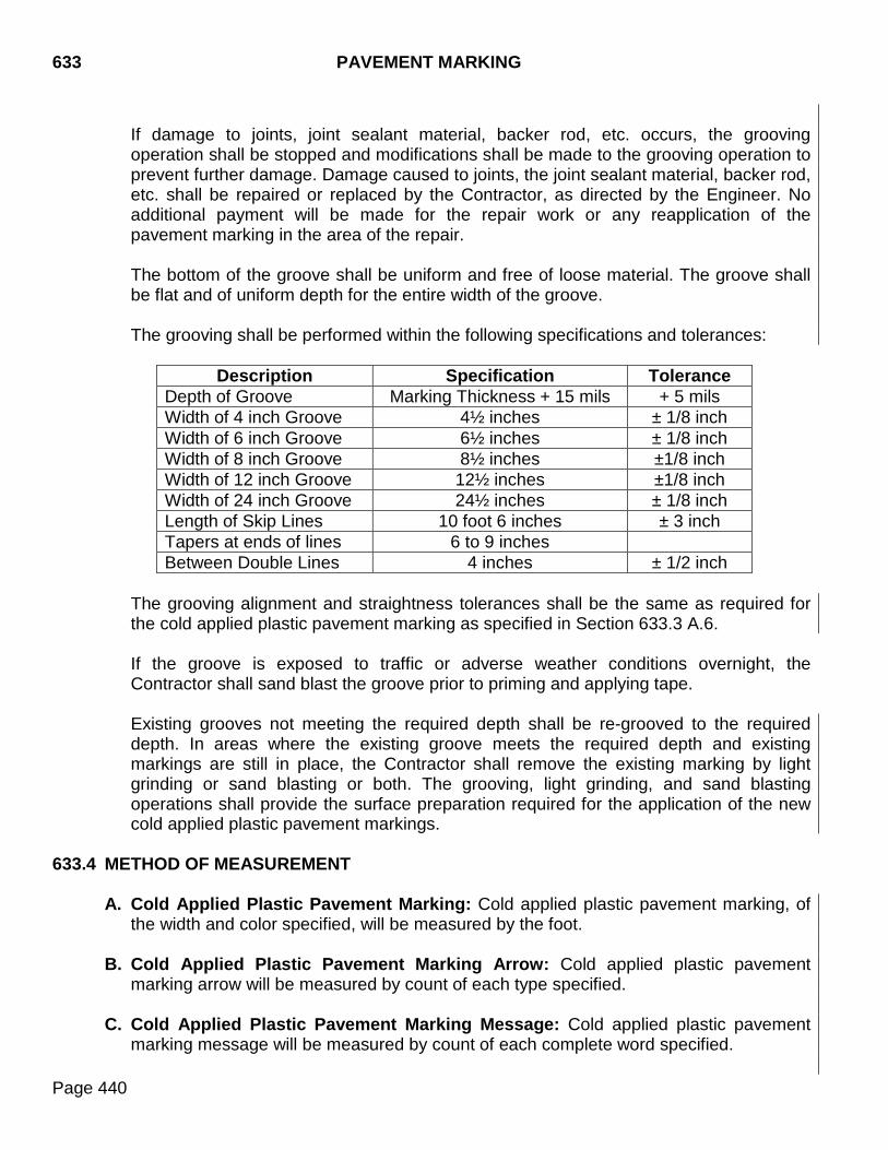
633 PAVEMENT MARKING
Page 440
If damage to joints, joint sealant material, backer rod, etc. occurs, the grooving operation shall be stopped and modifications shall be made to the grooving operation to prevent further damage. Damage caused to joints, the joint sealant material, backer rod, etc. shall be repaired or replaced by the Contractor, as directed by the Engineer. No additional payment will be made for the repair work or any reapplication of the pavement marking in the area of the repair. The bottom of the groove shall be uniform and free of loose material. The groove shall be flat and of uniform depth for the entire width of the groove. The grooving shall be performed within the following specifications and tolerances:
Description Specification Tolerance
Depth of Groove Marking Thickness + 15 mils + 5 mils Width of 4 inch Groove 4½ inches ± 1/8 inch Width of 6 inch Groove 6½ inches ± 1/8 inch Width of 8 inch Groove 8½ inches ±1/8 inch Width of 12 inch Groove 12½ inches ±1/8 inch Width of 24 inch Groove 24½ inches ± 1/8 inch Length of Skip Lines 10 foot 6 inches ± 3 inch Tapers at ends of lines 6 to 9 inches Between Double Lines 4 inches ± 1/2 inch
The grooving alignment and straightness tolerances shall be the same as required for the cold applied plastic pavement marking as specified in Section 633.3 A.6. If the groove is exposed to traffic or adverse weather conditions overnight, the Contractor shall sand blast the groove prior to priming and applying tape. Existing grooves not meeting the required depth shall be re-grooved to the required depth. In areas where the existing groove meets the required depth and existing markings are still in place, the Contractor shall remove the existing marking by light grinding or sand blasting or both. The grooving, light grinding, and sand blasting operations shall provide the surface preparation required for the application of the new cold applied plastic pavement markings.
633.4 METHOD OF MEASUREMENT
A. Cold Applied Plastic Pavement Marking: Cold applied plastic pavement marking, of the width and color specified, will be measured by the foot.
B. Cold Applied Plastic Pavement Marking Arrow: Cold applied plastic pavement
marking arrow will be measured by count of each type specified.
C. Cold Applied Plastic Pavement Marking Message: Cold applied plastic pavement marking message will be measured by count of each complete word specified.
PAVEMENT MARKING 633
Page 441
D. Cold Applied Plastic Pavement Marking Area: Cold applied plastic pavement marking area, of the color specified, will be measured to the nearest square foot.
E. Pavement Marking Paint and Beads: Paint and beads will be measured to the nearest
gallon of paint.
F. Grooving for Cold Applied Plastic Pavement Marking: Grooving for cold applied plastic pavement marking will be measured to the nearest foot,along the length of the groove for the width of grooving specified in the plans.
G. Grooving for Cold Applied Plastic Pavement Marking Arrow: Grooving for cold
applied plastic pavement marking arrow will be measured by the count of each arrow type specified.
H. Grooving for Cold Applied Plastic Pavement Marking Message: Grooving for cold
applied plastic pavement marking message will be measured by the count of each complete word specified.
I. Grooving for Cold Applied Plastic Pavement Marking Area: Grooving for cold
applied plastic pavement marking area will be measured to the nearest square foot. 633.5 BASIS OF PAYMENT
A. Cold Applied Plastic Pavement Marking: Cold applied plastic pavement marking of each width specified, will be paid for at the contract unit price per foot. Payment will be full compensation for equipment, labor, materials, and all incidentals required.
B. Cold Applied Plastic Pavement Marking Arrow: Cold applied plastic pavement
marking arrow of the type specified will be paid for at the contract unit price per each. Payment will be full compensation for equipment, labor, materials, and all incidentals required.
C. Cold Applied Plastic Pavement Marking Message: Cold applied plastic pavement
marking message will be paid for at the contract unit price per each word. Payment will be full compensation for equipment, labor, materials, and all incidentals required.
D. Cold Applied Plastic Pavement Marking Area: Cold applied plastic pavement
marking area will be paid for at the contract unit price per square foot. Payment will be full compensation for equipment, labor, materials, and all incidentals required.
E. Pavement Marking Paint and Beads: Paint and beads will be paid for at the contract
unit price per gallon for each color of pavement marking paint. Payment will be full compensation for furnishing paint and beads and for labor, equipment, and incidentals necessary.
F. Grooving for Cold Applied Plastic Pavement Marking: Grooving for cold applied
plastic pavement marking will be paid for at the contract unit price per foot for the width
633 PAVEMENT MARKING
Page 442
of groove specified. Payment will be full compensation for equipment, labor, materials, and all incidentals required.
G. Grooving for Cold Applied Plastic Pavement Marking Arrow: Grooving for cold
applied plastic pavement marking arrow will be paid for at the contract unit price per arrow type specified. Payment will be full compensation for equipment, labor, materials, and all incidentals required.
H. Grooving for Cold Applied Plastic Pavement Marking Message: Grooving for cold
applied plastic pavement marking message will be paid for at the contract unit price per each word specified. Payment will be full compensation for equipment, labor, materials, and all incidentals required.
I. Grooving for Cold Applied Plastic Pavement Marking Area: Grooving for cold
applied plastic pavement marking area will be paid for at the contract unit price per each square foot. Payment will be full compensation for equipment, labor, materials, and all incidentals required.
TEMPORARY TRAFFIC CONTROL 634
Page 443
634.1 DESCRIPTION This work consists of furnishing, installing, and maintaining required temporary traffic control devices in accordance with the current edition of the Federal Manual on Uniform Traffic Control Devices (MUTCD).
634.2 MATERIALS
Traffic and traffic control devices shall conform to and be maintained in accordance with the requirements of Section 984 and Part 6 of the MUTCD. Traffic control devices are categorized by their intended use and certification requirements.
• Category I traffic control devices are lightweight devices which may be self-certified by the manufacturer including, but not limited to; cones, drums, and delineators.
• Category II traffic control devices are other lightweight devices which must be certified by individual crash testing including, but not limited to; portable signs and barricades.
• Category III traffic control devices are fixed or other massive devices which must be certified by individual crash testing including, but not limited to; breakaway sign supports, concrete barriers, concrete barrier end protection, crash cushions, truck mounted attenuators, and longitudinal barriers.
• Category IV traffic control devices are trailer mounted devices which are not required to be individually crash tested including, but not limited to; portable changeable message signs, arrow boards, portable temporary traffic signals, and work area lighting.
Category I, II, and III traffic control devices shall meet the crashworthy requirements of test level 3 of National Cooperative Highway Research Program (NCHRP) Report 350 or AASHTO Manual for Assessing Safety Hardware (MASH). Category IV traffic control devices shall be delineated with retroreflective traffic control devices. Prior to use, the Contractor shall provide documentation for all traffic control devices used. The documentation shall show the traffic control devices used meet the applicable NCHRP 350 or MASH requirements. Retroreflective sheeting material used on traffic control devices shall conform to Section 984. Paint used for temporary pavement marking shall meet the same specification for permanent pavement marking in Section 980. Glass beads shall be used to reflectorize the temporary traffic paint. The glass beads shall conform to the requirements of Section 981. Pilot Cars shall conform to Section 984. Temporary pavement marking tape shall conform to Section 984.
634 TEMPORARY TRAFFIC CONTROL
Page 444
Signal heads shall meet the requirements of Section 985. Warning lights shall meet the requirements of Section 984.
634.3 CONSTRUCTION REQUIREMENTS
A. General: The Contractor shall furnish, install, and maintain required traffic control devices and pavement marking material.
1. All traffic control devices shall be kept in proper position, clean, and legible at all
times. Damaged devices shall be replaced within 24 hours, or as directed by the Engineer.
2. Non-applicable traffic control devices shall be completely covered or removed during
periods of inactivity. 3. Traffic control devices shall be immediately removed or covered when the need for
such devices no longer exists. When devices are no longer needed, they should be stored off the project or as close to the right-of-way line as possible.
4. Vehicles and equipment shall be stored outside the clear zone and as near as
possible to the right-of-way line. Contractor’s employees should mobilize at a location off the right-of-way and arrive at the work site in a minimum number of vehicles necessary to perform the work.
5. Traffic approaching the project from intersecting roadways, streets, and approaches must be adequately accommodated. Major intersections and large commercial entrances may require additional signing, flaggers, and channelizing devices on a temporary basis until work activities pass these areas.
6. Unless otherwise stated, hours of darkness are defined as 1/2 hour after sunset until
1/2 hour before sunrise.
B. Apparel: All workers within the right of way who are exposed either to traffic (vehicles using the highway for purposes of travel) or to construction equipment within the work area shall wear high-visibility safety apparel intended to provide conspicuity during both daytime and nighttime usage, and meeting the Performance Class 2 or 3 requirements of the ANSI/ISEA 107 publication entitled “American National Standard for High-Visibility Safety Apparel and Headwear” or equivalent revisions. Workers shall wear a vest, shirt, or jacket as an outer garment with a background color of fluorescent yellow-green, fluorescent orange-red, or fluorescent red. The retroreflectorized portion of the material shall be orange, yellow, white, yellow-green, or silver.
TEMPORARY TRAFFIC CONTROL 634
Page 445
C. Flagging: The Contractor shall provide each flagger with a copy of the "Flagger Manual". These manuals are available from the Department. Standards for flaggers and flagging practices shall conform to Part 6 of the MUTCD and the flagger manual. The Contractor shall furnish certified flaggers to perform project traffic control. The minimum age for flaggers shall be 18 years old. Flagger training and certification is available at some Department Area offices and from the Associated General Contractors (AGC). All flaggers shall complete a flagger training course and pass a written test to become certified. Flagger certification is valid for a period of 2 years. All flaggers shall be certified in South Dakota prior to flagging on the project. Flaggers shall carry proof of certification while flagging on Department projects. Flagger workstations shall be illuminated during hours of darkness. Flagger workstations shall be illuminated with a minimum of 108 lux (10 foot candles) of illumination. The Contractor shall perform a drive-through after dark to check for glare from the driver’s perspective and make adjustments necessary to eliminate or reduce the glare to the satisfaction of the Engineer. Flaggers shall be equipped with a STOP/SLOW sign for the control of traffic. The sign should be mounted on a staff from 5 to 7 feet long, from the bottom of the sign to the ground. All flagging devices and the use of such devices shall comply with Part 6 of the MUTCD, unless otherwise specified.
D. Pilot Car: Pilot cars and pilot car practices shall conform to Part 6 of the MUTCD. E. Traffic Control, Miscellaneous:
1. Channelizing Devices: Channelizing devices shall be reasonably plumb to the
pavement, safely and neatly ballasted as needed, clearly visible, and legible. Additional requirements for the use of specific channelizing devices are as follows: a. Cones: No additional requirements.
b. Barricades:
1) Type 1 Barricades: Type 1 barricades are for use on roads with normal
posted speeds of 40 mph or less. Type 1 barricades may also be used on higher speed roads provided the reflective area of the upper rail is at least 2 square feet.
2) Type 2 Barricades: No additional requirements.
c. Tubular Markers: Tubular markers shall not be used in lane closure tapers.
d. Vertical Panels: No additional requirements.
e. Direction Indicator Barricades: No additional requirements.
634 TEMPORARY TRAFFIC CONTROL
Page 446
f. Drums: No additional requirements.
2. Delineators: Delineators shall conform to Section 632.
3. Warning Lights: When used in conjunction with signs, barriers, and channelizing
devices; the warning light shall conform to Part 6 of the MUTCD. Vehicles and equipment working in traffic or alongside traffic shall be equipped with a flashing amber light visible from all directions at a minimum distance of 1/2 mile The amber light shall be mounted on the uppermost part of the Contractor’s vehicle. Lights must flash at 75 ±15 flashes per minute. Vehicle flasher/hazard lights are not acceptable.
4. Shadow Vehicles: Shadow vehicles shall conform to Part 6 of the MUTCD. Shadow vehicles shall be used as specified in the plans and for brooming operations unless otherwise directed. Shadow vehicles shall be a four-wheel motor vehicle with a flashing amber light. No separate payment will be made for shadow vehicles and any signs, warning lights, or other items associated with the shadow vehicles.
5. Inspection: The Contractor shall constantly monitor and maintain all traffic control
items. The Contractor is responsible for adjustments of traffic control items when traffic conditions change. The Contractor shall make weekly inspections after dark to verify the overall traffic control system is adequate and all devices are legible at night. This includes detour route signing. The weekly inspections shall begin when the first traffic control sign or device is put into operation and end when the last traffic control sign or device is removed from operation. The Contractor shall designate an employee whose primary responsibility is the maintenance of traffic and traffic control devices, 24 hours a day, 7 days a week. The person so designated must have training and experience in the field of construction traffic control and be knowledgeable about the MUTCD. The employee selected must be approved by the Engineer. The name, phone number, and location of the person(s) shall be provided to the Department, SD Highway Patrol, county sheriff’s office, and the local city police department. The person so designated shall submit a written report weekly to the Engineer. The reports shall document the daytime and weekly night time inspections.
F. Type 3 Barricades: Type 3 barricades shall conform to Part 6 of the MUTCD.
G. Flexible Delineators: Flexible delineators shall be used for delineation required within the outside edge of the finished shoulder. Flexible delineators shall match the color of the edge line. Flexible delineators shall be 28 inches long.
TEMPORARY TRAFFIC CONTROL 634
Page 447
H. Traffic Control Signs: Traffic control signs shall conform to Part 6 of the MUTCD and as specified in the plans.
I. Temporary Traffic Control Signal: Temporary traffic control signals shall generally
consist of all necessary materials and appurtenances needed to control road user movements at an intersection, bridge, or other site. 1. General: The Contractor shall furnish, operate, and maintain the temporary traffic
control signal. The temporary traffic control signal shall reliably and continuously control traffic for all approaches at the specified location. The temporary traffic control signal system shall meet the requirements of the MUTCD, national and local electrical codes, and these specifications. Existing signal equipment at the site may be salvaged for use in the temporary traffic control signal. Existing traffic signal equipment used on the project shall be salvaged or returned to original use as indicated in the plans. All materials furnished by the Contractor shall remain the property of the Contractor upon completion of the project. The temporary traffic control signal shall display pedestrian indications if the pedestrian indications previously existed, or if it is anticipated pedestrians will utilize the temporary traffic control signalized intersection. In the event of system failure, the Contractor shall furnish necessary flaggers to safely control traffic until the temporary traffic control signal is operable. The cost of flaggers, signing, and lighting shall be incidental to the contract price for temporary traffic control signal.
The Contractor shall have a qualified individual responsible for setup and maintenance of the temporary traffic control signal. This person shall have received training on installation, setup, and maintenance of the system. Traffic signal operation or maintenance work is required to be performed by the Contractor when project conditions dictate, lane closures change, traffic flow is impeded, a potential risk to the public exists, or when equipment breaks down or malfunctions. Equipment break downs or malfunctions require a high priority response and are to be reacted to within one hour of notification of the event.
2. Temporary Traffic Control Signal Equipment: a. Short Term Temporary Traffic Control Signal: The short term temporary traffic
control signal system shall consist of signal heads mounted on span wire supports.
b. Portable Temporary Traffic Control Signal: The portable temporary traffic
control signal system shall consist of signal heads, controller, and power supply, all mounted on a heavy duty trailer.
634 TEMPORARY TRAFFIC CONTROL
Page 448
One of the signal heads shall be mounted a minimum of 17 feet and a maximum of 19 feet above the roadway surface on the mast arm. The other signal head shall be mounted at least 8 feet but not more than 15 feet above the roadway surface. The signal heads shall have the ability to be rotated 180 degrees to face in either direction. The signal heads shall also have the ability to be rotated in the vertical or horizontal plane so as to have the optimum visibility to the motorist. Signals shall be located so as to meet the visibility requirements of the MUTCD. The portable temporary traffic control signal shall be equipped with work zone safety lights located on the back side of the signal heads to alert construction workers of the status of the traffic signal.
3. Temporary Traffic Control Signal Support: The support system, with traffic signal
heads, shall be designed in accordance with the current edition of the AASHTO Standard Specifications for Highway Signs, Luminaires, and Traffic Signals. The design wind velocity shall be 90 mph.
a. Short Term Temporary Traffic Control Signal: The Contractor shall furnish
and install span wire supports. Guy wire anchors shall be used as design requires. The Contractor shall determine the size of span support wire, span tether wire, pole type, and guy wire required.
Design and check design calculations for the span wire and support system (span wire, tether wire, poles, arms, connections, guy wires, and anchors, footings, anchor bolts, etc.) shall be signed and sealed by a Professional Engineer registered in the state of South Dakota and shall be submitted with shop drawings in accordance with Section 985.1 I.3. The Contractor shall complete tree trimming, as necessary.
b. Portable Temporary Traffic Control Signal: The temporary traffic control signal
shall be designed to support the signal heads required.
Signal supports should be located as far as practical from the edge of the traveled way without adversely affecting the visibility of signal indications. Temporary signal trailers are not to be parked in areas or lanes open to traffic.
The Contractor shall adjust the traffic signals as necessary for the various phases of the work and traffic conditions to meet MUTCD criteria for sight distances and sight triangles. This includes the relocation or realignment of traffic signal indications as project conditions require.
The Contractor shall complete tree trimming, as necessary.
TEMPORARY TRAFFIC CONTROL 634
Page 449
4. Power: a. Short Term Temporary Traffic Control Signal: The Contractor shall provide
power to the temporary traffic control signal system. The monthly fee for power used by the short term temporary traffic control signal system shall be paid for by the Contractor.
b. Portable Temporary Traffic Control Signal: The power source for the unit shall be one of the following: an engine generator unit, a solar powered unit, or a 110 volt AC power source. Solar powered units shall have a solar array charging system capable of operating without external charge for a minimum of 20 days during all seasons. The system shall monitor alternator or charging system and battery voltage. The master trailer (controller) shall monitor all functions of remote trailers and display all conditions. The remote trailers shall also provide the status of all functions for that particular remote trailer. If a low power condition occurs, the controller software shall automatically switch the trailer to a minimum power mode to preserve battery power. The Contractor shall be responsible for providing backup power if the main power source fails. The backup power supply shall be able to operate the traffic signals for a minimum of 48 hours.
5. Controller: The controller shall be capable of operating pre-timed, actuated, and by
manual control. a. Short Term Temporary Traffic Control Signal: The short term temporary traffic
control signal shall operate from a controller at the site. The controller and the controller cabinet shall meet the requirements of Section 985 with the following deviations:
1) Battery backup is not required.
2) The controller cabinet shall be a NEMA Type M enclosure capable of pole
mounting with cable conduit opening(s) in the center bottom.
b. Portable Temporary Traffic Control Signal: The portable temporary traffic control signal units shall operate from one master controller at a given site. The second controller or additional slave units shall be controlled by the master unit.
The controller shall have an operating temperature range from -40 to +120°F.
6. Vehicle Detection: The system shall be capable of video, loop, microwave, or radar
detection.
7. Traffic Signal Programming: The Contractor shall program the controllers with the traffic signal programming that is provided in the project plans. Should the project plans not specify a traffic signal program, the State shall provide the traffic signal programming in writing. As project conditions and traffic needs change, the Contractor will adjust the traffic signal splits and offsets as directed by the Engineer.

634 TEMPORARY TRAFFIC CONTROL
Page 450
J. Arrow Boards: On roads with normal posted speeds of 45 mph and above, Type C units shall be used for all operations 24 hours or more in duration and Type B units may be used for operations less than 24 hours in duration. On roads with normal posted speeds less than 45 mph, Type A, B, or C, units may be used for all operations.
Type A: 48 inches x 24 inches, visible for a minimum of 1/2 mile Type B: 60 inches x 30 inches, visible for a minimum of 3/4 mile Type C: 98 inches x 48 inches, visible for a minimum of 1 mile
K. Portable Changeable Message Signs: Portable changeable message signs shall conform to Part 6 of the MUTCD except the minimum mounting height may be lowered, as approved by the Region Traffic Engineer. The Contractor shall furnish, place, operate, and maintain the Portable Changeable Message Signs (PCMS) at the locations shown on the plans. The Contractor shall maintain possession of the PCMS upon completion of the project.
L. Temporary Pavement Marking:
1. General: Temporary pavement markings shall be maintained in good condition until
the permanent pavement marking is in place, or until the Area office issues the letter of Acceptance of Field Work. All roadways open to traffic (including, but not limited to, newly paved surfaces, cold milled surfaces, asphalt surface treatments, flush seals, fog seals, and tack coats) shall have temporary dashed centerline markings, no passing zone markings, and applicable lane lines placed prior to nightfall. For prime coats, the existing signing shall remain in place until the prime coat has cured for 72 hours and temporary pavement marking is installed. Following the 72 hour cure period for prime coats, the Contractor shall install temporary dashed centerline markings, no passing zone markings, and applicable lane lines prior to nightfall. Interstate highways shall also be marked with edge lines prior to nightfall. Unless otherwise shown on the plans, centerline and the applicable lane lines may be temporarily marked by temporary pavement marking tape, temporary raised pavement markers, temporary flexible vertical markers (tabs), or temporary pavement marking paint. The material used to mark the no passing zones shall be the same type of material used to mark the temporary dashed centerline, unless otherwise approved by the Engineer. For 2 lane roadways with average daily traffic volumes of 2500 or less, no passing zones may be identified using DO NOT PASS and PASS WITH CARE signs rather than pavement markings. The DO NOT PASS signs shall be used to mark the beginning of each no passing zone, and the PASS WITH CARE signs to mark the end of each zone. These may be utilized in place of the pavement markings normally used to identify no passing zones for no longer than 14 calendar days. The
TEMPORARY TRAFFIC CONTROL 634
Page 451
placement of the dashed centerline marking and these signs shall be required prior to nightfall. The Contractor shall take the steps necessary to ensure the temporary markings on the final surface will match the markings on the existing surface.
The Engineer will determine locations and limits of no passing zones in accordance with Part 3 of the MUTCD.
2. Materials for Temporary Pavement Marking: Temporary pavement marking tape, temporary raised pavement markers, temporary flexible vertical markers (tabs), and temporary pavement marking paint shall be of the type specified and shall meet the following requirements.
a. Temporary Pavement Marking Tape: Temporary pavement marking tape shall
be applied according to the manufacturer's recommendations. Tape used for dashed centerline marking shall be applied in 4 inch widths, 2 feet long with a cycle length of 40 feet. A 2 foot stripe with a cycle length of 20 feet may be used for roadways with severe curvature. Solid stripes shall consist of tape applied in 4 inch widths for the length specified.
b. Temporary Raised Pavement Markers: Temporary raised pavement markers
shall be applied according to the manufacturer's recommendations. 4 inch wide reflectorized markers may be used in place of tape or paint. If temporary raised pavement markers are used to substitute for dashed centerlines, the dashed centerline shall be a 4 foot long line with a cycle length of 40 feet. A 2 foot long line with a cycle length of 20 feet shall be used for roadways with severe curvature. Two temporary raised pavement markers shall represent the dashed centerline, one at each end of the line. A solid line shall be represented by a 5 foot spacing.
c. Temporary Flexible Vertical Markers (Tabs): Temporary flexible vertical markers (tabs) shall be applied according to the manufacturer's recommendations. 4 inch wide reflectorized markers may be used in place of tape or paint. If temporary flexible vertical markers (tabs) are used to substitute for dashed centerlines, the dashed centerline shall be a 4 foot long line with a cycle length of 40 feet. A 2 foot long line with a cycle length of 20 feet shall be used for roadways with severe curvature. Two temporary flexible vertical markers shall represent the dashed centerline, one at each end of the line. A solid line shall be represented by a 5 foot spacing.
When an asphalt surface treatment, fog seal, or flush seal are to be applied, temporary flexible vertical markers (tabs) shall not be placed more than 72 hours prior to covering the in place markings on the surface. The protective marker
634 TEMPORARY TRAFFIC CONTROL
Page 452
covers shall not be removed until after all oil within 2 feet of the markers has been applied and rolling has been completed.
d. Temporary Pavement Marking Paint: Temporary pavement marking paint shall be applied in accordance with Section 633 except as modified by the following:
Dashed centerlines shall be applied in 4 inch widths 4 feet long at cycle lengths of 40 feet. A 2 foot long line at cycle lengths of 20 feet may be used for roadways with severe curvature. Solid lines shall be 4 inches wide for the length specified or required. The paint applicator shall be a self-propelled pneumatic spraying machine with atomizing nozzles capable of applying a minimum of two lines at one time from 4 to 8 inches wide. When only one lane of a two-lane roadway is complete at the end of a day, the temporary marking shall be placed near centerline on the unsurfaced portion of the roadway.
M. Removal of Pavement Markings: Pavement markings to be removed shall be designated by the Engineer. Pavement markings shall be removed from the pavement by methods that do not damage the surface or texture of the pavement. Pavement markings shall be removed before the traffic pattern is changed. Covering the markings is not acceptable removal. Sand or other material used for removal shall be disposed of as the work progresses. Accumulations of sand or other material, which interferes with drainage or constitutes a hazard to traffic, will not be permitted. When sand blasting is used for removal of pavement markings or objectionable material, and the removal operation is performed within 10 feet of a lane occupied by the traveling public, the residue including dust, shall be removed immediately by a vacuum attachment operating concurrently with the sand blasting operation.
Damage to the pavement surface caused by pavement marking removal shall be repaired at the expense of the Contractor.
634.4 METHOD OF MEASUREMENT
A. Flagging: Flagging will be measured to the nearest 0.5 hour a flagger is performing flagging work. A record of the number of flagger hours used will be submitted to the Engineer.
TEMPORARY TRAFFIC CONTROL 634
Page 453
B. Pilot Car: Pilot car will be measured to the nearest 0.5 hour a pilot car is performing pilot car work. A record of the number of pilot car hours used will be submitted to the Engineer.
C. Traffic Control, Miscellaneous: Measurement for traffic control, miscellaneous will not
be made. D. Type 3 Barricades: Type 3 barricades, of the type and length specified, will be
measured per each used on the project. Measurement for Type 3 barricades will be made one time even if the Type 3 barricades are moved or replaced. The number of Type 3 barricades measured will be the greatest number of installations in place at any one time, regardless of the number of setups throughout the duration of the project.
E. Flexible Delineators: Flexible delineators will be measure per each used on the project.
F. Traffic Control Signs: Traffic control signs will be measured to the nearest square foot.
Measurement for traffic control signs will be made one time even if the traffic control signs are moved or replaced. The amount of traffic control signs measured will be the greatest number of installations in place at any one time, regardless of the number of setups throughout the duration of the project.
G. Temporary Traffic Control Signal:
1. Short Term Temporary Traffic Control Signal: Measurement for a short term temporary traffic control signal will be made on a per site basis. One site will be considered to be all signals, overhead span wires, support poles, and other equipment in use at an intersection.
2. Portable Temporary Traffic Control Signal: Measurement for a portable
temporary traffic control signal will be made on a per each basis. One unit will be considered to be a portable traffic control signal mounted on a trailer.
H. Arrow Board: Arrow boards will be measured on a per each basis of the total number
of arrow boards used on the project. Measurement for arrow boards will be made one time even if the arrow boards are moved or replaced. The amount of arrow boards measured will be the greatest number of arrow boards on the project at any one time, regardless of the number of setups throughout the duration of the project.
I. Portable Changeable Message Sign: Portable changeable message signs will be
measured on a per each basis of the total number of portable changeable message signs used on the project. Measurement for portable changeable message signs will be made one time even if the portable changeable message signs are moved or replaced. The amount of portable changeable message signs will be the greatest number of portable changeable message signs on the project at any one time, regardless of the number of setups throughout the duration of the project.
634 TEMPORARY TRAFFIC CONTROL
Page 454
J. Temporary Pavement Marking: Measurement for tape, paint, tabs, and raised pavement markers will be made either by the foot or by the mile depending on the unit designated by the contract quantity. A single measurement will be made longitudinally along the centerline of the roadway. The resulting single measured distance will be the quantity used for payment for all temporary pavement markings including, but not limited to, temporary dashed centerline, lane lines, edge lines, gore lines, no passing zone lines, and Do Not Pass and Pass With Care signing (if utilized). Separate measurement and determination of quantity for each individual temporary pavement marking line will not be made. Each surface course or surface treatment receiving temporary pavement marking will be measured to the nearest 0.1 mile increment for payment. If a single set of temporary roadway markers is utilized on multiple surface courses or surface treatments, payment will be made as though each surface course or surface treatment was marked separately. Temporary pavement markings applied to sections of the roadway due to the application of tack will not be measured for payment. The temporary pavement markings placed near the centerline on the unsurfaced portion of the roadway when only one lane of the final surface course or surface treatment is complete will not be measured for payment.
K. Remove Pavement Marking: Measurement for removal of pavement markings will not be made. The plan quantity will be used for payment unless additional pavement marking removal is ordered by the Engineer.
634.5 BASIS OF PAYMENT
A. Flagging: Payment for flagging will include all costs for provided certified flagger, stop/slow paddle, flag, and any nighttime illumination required. The accepted number of flagging hours will be paid for at the rate specified in the Special Provision for Price Schedule for Miscellaneous Items.
B. Pilot Car: Pilot car will be paid for at the contract unit price per hour. The accepted
number of pilot car hours will be paid for at the rate specified in the Special Provision for Price Schedule for Miscellaneous Items.
C. Traffic Control, Miscellaneous: Payment for traffic control, miscellaneous will include
all costs for installation, maintenance, and removal of all cones; Type 1 and Type 2 barricades; tubular markers; vertical panels; direction indicator barricades; drums; flashing warning lights; and flags on signs. Payment will include all costs for removing and covering non-applicable traffic control devices, shadow vehicles, traffic control inspections, reporting for traffic control inspections, and the designated traffic control contact person.
D. Type 3 Barricades: Payment for Type 3 barricades will include all cost for installation,
maintenance, and removal.
TEMPORARY TRAFFIC CONTROL 634
Page 455
E. Flexible Delineators: Payment for flexible delineators will include all cost for installation, maintenance, and removal.
F. Traffic Control Signs: Traffic control signs will be paid for by the square foot. Payment
for traffic control signs will be made following satisfactory installation. Payment will be full compensation for installing, maintaining, relocating, and removing traffic control signs and supports. Hinged signs and signs with tabs, such as right and left signs, will be paid for as one sign. Costs for posts and supports shall be included in the contract unit price of the sign.
Additional payment will not be made for any traffic control sign turned away, covered, or temporarily taken out of service and returned to service. If a fixed location traffic control sign is relocated due to an error in the plans or by the Engineer, an additional 50% of the designated sign rate will be paid. The Contractor’s failure to maintain, relocate, or remove traffic control signs and supports as required will result in a price adjustment assessed to the contract.
G. Temporary Traffic Control Signal:
1. Short Term Temporary Traffic Control Signal: Short term temporary traffic control signals will be paid for at the contract unit price per each site. Payment will be full compensation for furnishing, installing, maintaining, tree trimming, and all other incidentals for the short term temporary traffic control signal, which may include using existing controller and signal heads or providing new controller and signal heads, as designated in the plans.
2. Portable Temporary Traffic Control Signal: Portable temporary traffic control
signals will be paid for at the contract unit price per each unit. Payment will be full compensation for furnishing, installing, maintaining, relocating, tree trimming, and all other incidentals for the portable temporary traffic control signal.
H. Arrow Board: Arrow boards will be paid for at the contract unit price per each. Payment
will be full compensation for labor, equipment, materials, delivery, installation, maintenance, relocation, and removal.
I. Portable Changeable Message Sign: Portable changeable message signs will be paid
for at the contract unit price per each. Payment will be full compensation for labor, equipment, materials, delivery, installation, maintenance, relocation, and removal.
J. Temporary Pavement Marking: Payment for temporary pavement marking will be by
the mile or foot. Payment will be considered total payment for all required temporary pavement markings, including but not limited to, temporary dashed centerline, lane lines, edge lines, gore lines, no passing zone lines, and Do Not Pass and Pass with Care signing (if utilized). Payment will be full compensation for all costs to furnish, install, and remove (when required) temporary pavement markings including costs to

634 TEMPORARY TRAFFIC CONTROL
Page 456
remove and properly dispose of temporary road marker covers, temporary road markers, and temporary pavement marking tape.
K. Remove Pavement Marking: Payment for removal of pavement markings will be by the foot, each, word, or square foot depending on the bid item unit description. Payment will be full compensation for all costs to remove and properly dispose of the pavement markings.
TRAFFIC SIGNALS AND ROADWAY LIGHTING 635
Page 457
635.1 DESCRIPTION This work consists of furnishing and installing all material and equipment necessary for the operation of traffic signals and roadway lighting.
635.2 MATERIALS
Materials for traffic signals and roadway lighting shall conform to Section 985. Equipment and materials furnished shall be new.
635.3 CONSTRUCTION REQUIREMENTS
A. General
Installations shall comply with applicable sections of the National Electrical Code (NEC), State regulations, and local ordinances. Licenses or permits required shall be obtained by and at the expense of the Contractor. The Contractor shall arrange for necessary electrical services at locations specified, as agreed to by the Department and the utility company. Upon completion of a roadway lighting project an operating test shall be conducted. The equipment shall be demonstrated to operate in a safe and proper manner. The Contractor shall pay all costs associated with the testing of the luminaires. The Contractor shall provide required equipment to make the following tests:
1. Resistance to ground on non-grounded conductors shall be at least 5 megohm at
60ºF measured with a 1000 volt megger. The ground resistance shall not be more than 25 ohms.
2. Voltage readings shall be made at each service pole in the load contactor with load
and without load, and at each fixture with load.
3. Current readings shall be made on the load side of each load contactor phase and neutral. Readings shall be made at nighttime with lighting systems in normal operation.
4. Data obtained from the tests shall be furnished in writing. After the traffic signals and the lighting system have been turned on and found to be operating satisfactorily and all installation of the system is complete, the Engineer shall notify the Contractor of acceptance. Upon acceptance, the Contractor shall be relieved of routine maintenance responsibility. The Contractor shall remain responsible for failures due to character of work, materials, or equipment that occur during a one year period following the date of acceptance. The Contractor shall warrant and guarantee materials, electrical, and mechanical equipment furnished and installed to be free from defects in materials and character of work in accordance with the following:
635 TRAFFIC SIGNALS AND ROADWAY LIGHTING
Page 458
Warranties and guarantees offered by electrical and mechanical equipment manufacturers shall be turned over to the maintaining authority at the time of acceptance of the project. The maintaining authority shall be named as the obligee on all manufacturer warranties and guarantees. The Contractor shall warrant and guarantee satisfactory in-service operations of electrical and mechanical equipment, and related components, and shall replace or correct parts found to be defective within a one year period. Compensation will not be made for replacements or corrections. The warranty and guarantee requirements shall not apply to parts of electrical and mechanical equipment which have been subjected to misuse, negligence, or accident by other parties.
B. Electrical Grounding and Bonding: Grounding and bonding shall be in compliance
with the NEC, local ordinances, and local utility company rules.
C. Conduit: Use and installation shall conform to NEC and the following requirements:
1. The size of the conduits installed shall not be less than the electrical trade size specified.
2. The location and direction of conduit runs is diagrammatic and may be shifted to
meet field conditions.
3. Underground conduit shall be placed by trenching, jacking, or drilling methods. The use of the trenching method for placement under existing roadway pavements will be permitted only after jacking or drilling attempts have failed. The Contractor shall not use equipment requiring flowing water for installation of conduit under streets or roadways unless approved by the Engineer. Trenches shall be backfilled and compacted to the same density as the adjoining ground. Roadway surfaces, sidewalks, curb and gutters, sod, etc., which are removed by trenching operations shall be replaced. The cost of removing and replacing these materials shall be incidental to the bid price for the conduit.
4. Where trenching operations require the removal of concrete pavement or sidewalk,
the concrete shall be sawed full depth along the removal lines or the concrete shall be removed to existing joints.
5. Conduit entering through junction or pull box walls shall terminate approximately 2
inches in from the inside wall and not less than 2 inches above the bottom. The diameter of the holes in the junction or pull box walls shall be no more than 1/4 inch larger than the diameter of the conduit. The area around the conduit shall be sealed with a waterproof silicone sealant.
6. Conduit entering the traffic signal cabinet shall be sealed with paraffin or other
approved sealing compounds to prevent the entrance of gases. The height of the conduit shall not exceed 2 inches above the cabinet base.
TRAFFIC SIGNALS AND ROADWAY LIGHTING 635
Page 459
7. Metal conduit open ends in junction boxes or above concrete foundations shall be provided with an approved threaded conduit grounding bushing. Nonmetallic conduit open ends shall have an approved bell end or bushing installed to prevent damage to cable or conductors.
8. Metal conduit ends shall be reamed to remove sharp edges and burrs. Threads on
threaded conduit shall be painted with a good quality lead or rust preventive paint as the couplings are made up. Couplings shall be tightened until the ends of the conduit are brought together.
D. Concrete Footings: The bottom of concrete footings shall rest on firm ground. The
sides of the footings shall be formed by using an auger and then placing the concrete against the natural soil. A suitable form shall be used above existing ground line and all exposed portions shall be formed to present a neat appearance. The above ground portion of the footing shall be formed of sufficient size and shape so no part of the pole base, including transformer type bases, shall overhang or protrude beyond the footing. An acceptable form shall be used if the excavation is larger than the standard footing dimensions. Backfill must be replaced to a density equal to or greater than the adjacent undisturbed natural soil. The top of the concrete footing shall be finished smooth and shall be level after anchor bolt/rod installation. A 1/2 inch conduit for grounding wire raceway shall be installed through the footing. Ground rods shall be a minimum of 2 feet from the footing.
E. Anchor Bolts/Rods: Anchor bolts/rods shall be installed in accordance with the following
requirements:
1. General: Anchor bolts/rods shall be provided with all hardware required for attaching and leveling in accordance with the manufacturer’s recommendations.
2. Anchor Bolt/Rod Installation: A steel template shall be used to accurately locate
and hold the anchor bolts/rods plumb and in proper alignment. This template shall be in place during placement of the concrete base and shall remain in place a minimum of 24 hours after the concrete placement has been completed. Out of position anchor bolts/rods and anchor bolts/rods greater than 1:40 out-of-plumb are cause for rejection of the base. Bending of the anchor bolts/rods to straighten or move into position, or alterations of the pole base plate will not be permitted.
3. Anchor Bolt/Rod Tightening: Breakaway transformer bases shall be tightened in
accordance with the manufacturer’s recommendations. All others shall be tightened in accordance with the following:
a. All leveling nuts (bottom nuts) shall be brought to full bearing on the bottom of the
base plate. The bottom of the leveling nuts must be kept as close to the concrete base as practical, and shall not be more than one anchor bolt/rod diameter above the top of the concrete base. Leveling nuts must be threaded onto the anchor
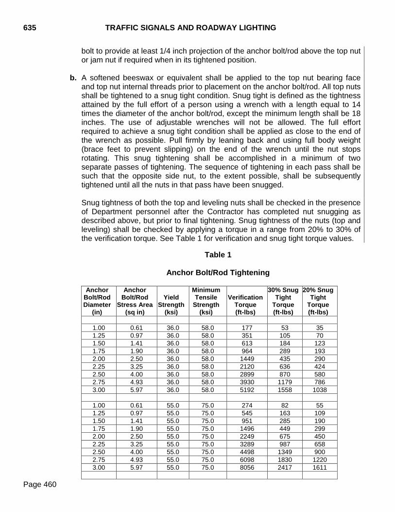
635 TRAFFIC SIGNALS AND ROADWAY LIGHTING
Page 460
bolt to provide at least 1/4 inch projection of the anchor bolt/rod above the top nut or jam nut if required when in its tightened position.
b. A softened beeswax or equivalent shall be applied to the top nut bearing face
and top nut internal threads prior to placement on the anchor bolt/rod. All top nuts shall be tightened to a snug tight condition. Snug tight is defined as the tightness attained by the full effort of a person using a wrench with a length equal to 14 times the diameter of the anchor bolt/rod, except the minimum length shall be 18 inches. The use of adjustable wrenches will not be allowed. The full effort required to achieve a snug tight condition shall be applied as close to the end of the wrench as possible. Pull firmly by leaning back and using full body weight (brace feet to prevent slipping) on the end of the wrench until the nut stops rotating. This snug tightening shall be accomplished in a minimum of two separate passes of tightening. The sequence of tightening in each pass shall be such that the opposite side nut, to the extent possible, shall be subsequently tightened until all the nuts in that pass have been snugged. Snug tightness of both the top and leveling nuts shall be checked in the presence of Department personnel after the Contractor has completed nut snugging as described above, but prior to final tightening. Snug tightness of the nuts (top and leveling) shall be checked by applying a torque in a range from 20% to 30% of the verification torque. See Table 1 for verification and snug tight torque values.
Table 1
Anchor Bolt/Rod Tightening
Anchor
Bolt/Rod Diameter
(in)
Anchor Bolt/Rod
Stress Area (sq in)
Yield
Strength (ksi)
Minimum Tensile
Strength (ksi)
Verification
Torque (ft-lbs)
30% Snug Tight
Torque (ft-lbs)
20% Snug Tight
Torque (ft-lbs)
1.00 0.61 36.0 58.0 177 53 35 1.25 0.97 36.0 58.0 351 105 70 1.50 1.41 36.0 58.0 613 184 123 1.75 1.90 36.0 58.0 964 289 193 2.00 2.50 36.0 58.0 1449 435 290 2.25 3.25 36.0 58.0 2120 636 424 2.50 4.00 36.0 58.0 2899 870 580 2.75 4.93 36.0 58.0 3930 1179 786 3.00 5.97 36.0 58.0 5192 1558 1038
1.00 0.61 55.0 75.0 274 82 55 1.25 0.97 55.0 75.0 545 163 109 1.50 1.41 55.0 75.0 951 285 190 1.75 1.90 55.0 75.0 1496 449 299 2.00 2.50 55.0 75.0 2249 675 450 2.25 3.25 55.0 75.0 3289 987 658 2.50 4.00 55.0 75.0 4498 1349 900 2.75 4.93 55.0 75.0 6098 1830 1220 3.00 5.97 55.0 75.0 8056 2417 1611
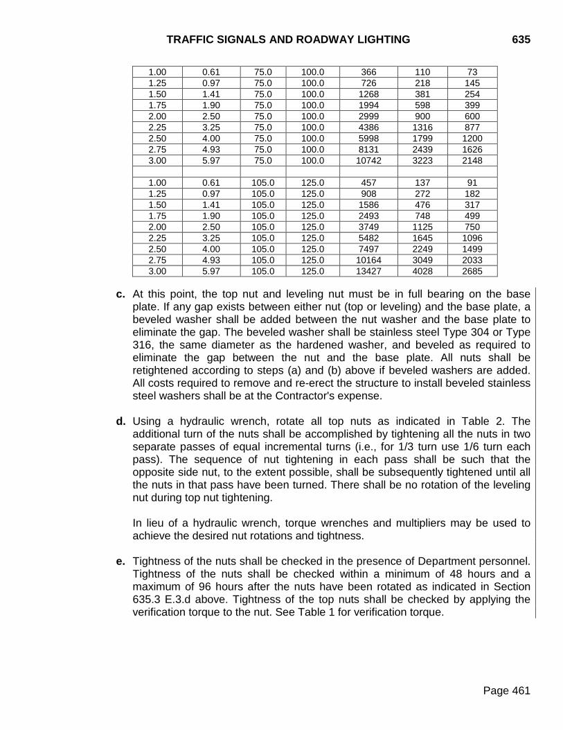
TRAFFIC SIGNALS AND ROADWAY LIGHTING 635
Page 461
1.00 0.61 75.0 100.0 366 110 73 1.25 0.97 75.0 100.0 726 218 145 1.50 1.41 75.0 100.0 1268 381 254 1.75 1.90 75.0 100.0 1994 598 399 2.00 2.50 75.0 100.0 2999 900 600 2.25 3.25 75.0 100.0 4386 1316 877 2.50 4.00 75.0 100.0 5998 1799 1200 2.75 4.93 75.0 100.0 8131 2439 1626 3.00 5.97 75.0 100.0 10742 3223 2148
1.00 0.61 105.0 125.0 457 137 91 1.25 0.97 105.0 125.0 908 272 182 1.50 1.41 105.0 125.0 1586 476 317 1.75 1.90 105.0 125.0 2493 748 499 2.00 2.50 105.0 125.0 3749 1125 750 2.25 3.25 105.0 125.0 5482 1645 1096 2.50 4.00 105.0 125.0 7497 2249 1499 2.75 4.93 105.0 125.0 10164 3049 2033 3.00 5.97 105.0 125.0 13427 4028 2685
c. At this point, the top nut and leveling nut must be in full bearing on the base
plate. If any gap exists between either nut (top or leveling) and the base plate, a beveled washer shall be added between the nut washer and the base plate to eliminate the gap. The beveled washer shall be stainless steel Type 304 or Type 316, the same diameter as the hardened washer, and beveled as required to eliminate the gap between the nut and the base plate. All nuts shall be retightened according to steps (a) and (b) above if beveled washers are added. All costs required to remove and re-erect the structure to install beveled stainless steel washers shall be at the Contractor's expense.
d. Using a hydraulic wrench, rotate all top nuts as indicated in Table 2. The
additional turn of the nuts shall be accomplished by tightening all the nuts in two separate passes of equal incremental turns (i.e., for 1/3 turn use 1/6 turn each pass). The sequence of nut tightening in each pass shall be such that the opposite side nut, to the extent possible, shall be subsequently tightened until all the nuts in that pass have been turned. There shall be no rotation of the leveling nut during top nut tightening.
In lieu of a hydraulic wrench, torque wrenches and multipliers may be used to achieve the desired nut rotations and tightness.
e. Tightness of the nuts shall be checked in the presence of Department personnel.
Tightness of the nuts shall be checked within a minimum of 48 hours and a maximum of 96 hours after the nuts have been rotated as indicated in Section 635.3 E.3.d above. Tightness of the top nuts shall be checked by applying the verification torque to the nut. See Table 1 for verification torque.
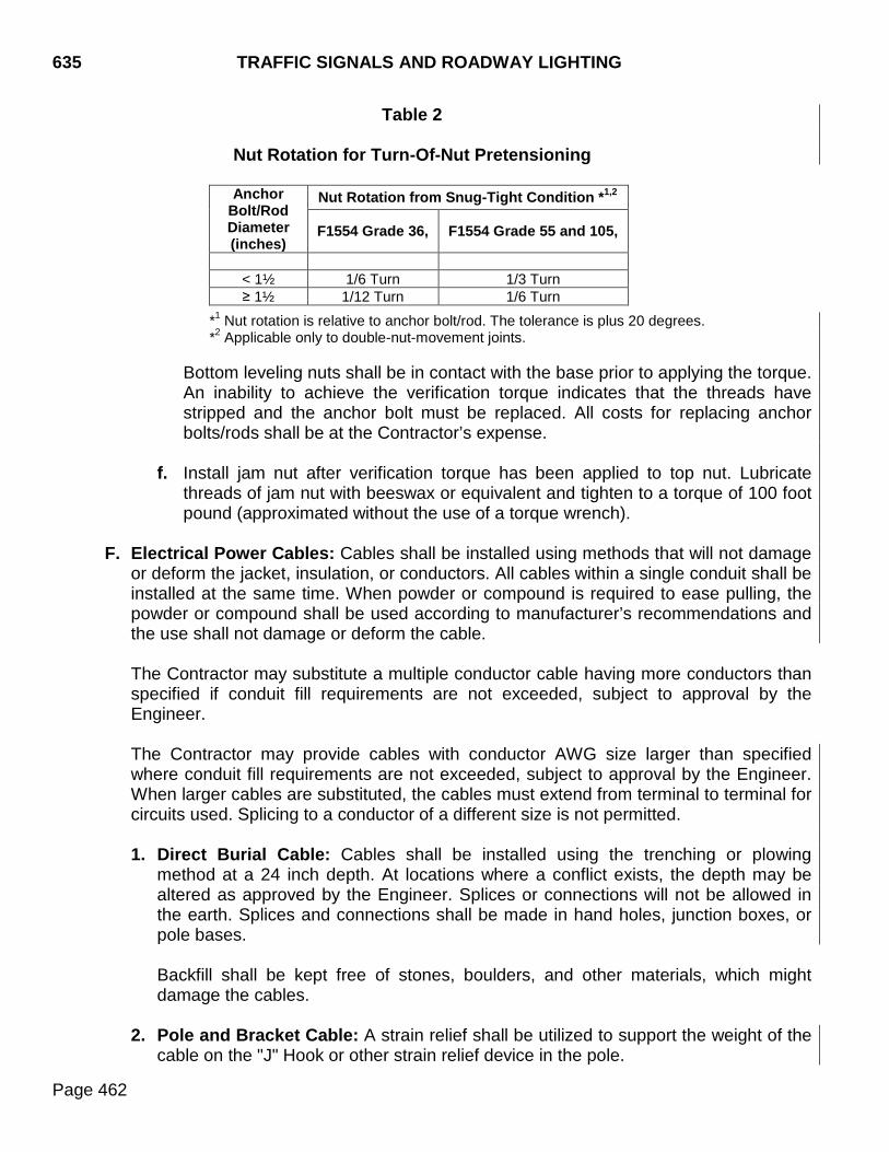
635 TRAFFIC SIGNALS AND ROADWAY LIGHTING
Page 462
Table 2
Nut Rotation for Turn-Of-Nut Pretensioning
Anchor Bolt/Rod Diameter (inches)
Nut Rotation from Snug-Tight Condition *1,2
F1554 Grade 36, F1554 Grade 55 and 105,
< 1½ 1/6 Turn 1/3 Turn ≥ 1½ 1/12 Turn 1/6 Turn
*1 Nut rotation is relative to anchor bolt/rod. The tolerance is plus 20 degrees. *2 Applicable only to double-nut-movement joints.
Bottom leveling nuts shall be in contact with the base prior to applying the torque. An inability to achieve the verification torque indicates that the threads have stripped and the anchor bolt must be replaced. All costs for replacing anchor bolts/rods shall be at the Contractor’s expense.
f. Install jam nut after verification torque has been applied to top nut. Lubricate threads of jam nut with beeswax or equivalent and tighten to a torque of 100 foot pound (approximated without the use of a torque wrench).
F. Electrical Power Cables: Cables shall be installed using methods that will not damage
or deform the jacket, insulation, or conductors. All cables within a single conduit shall be installed at the same time. When powder or compound is required to ease pulling, the powder or compound shall be used according to manufacturer’s recommendations and the use shall not damage or deform the cable. The Contractor may substitute a multiple conductor cable having more conductors than specified if conduit fill requirements are not exceeded, subject to approval by the Engineer. The Contractor may provide cables with conductor AWG size larger than specified where conduit fill requirements are not exceeded, subject to approval by the Engineer. When larger cables are substituted, the cables must extend from terminal to terminal for circuits used. Splicing to a conductor of a different size is not permitted. 1. Direct Burial Cable: Cables shall be installed using the trenching or plowing
method at a 24 inch depth. At locations where a conflict exists, the depth may be altered as approved by the Engineer. Splices or connections will not be allowed in the earth. Splices and connections shall be made in hand holes, junction boxes, or pole bases. Backfill shall be kept free of stones, boulders, and other materials, which might damage the cables.
2. Pole and Bracket Cable: A strain relief shall be utilized to support the weight of the
cable on the "J" Hook or other strain relief device in the pole.
TRAFFIC SIGNALS AND ROADWAY LIGHTING 635
Page 463
G. Traffic Signal Control Cables: Traffic signal conductors shall be continuous from the
controller cabinets to the pole bases. Splicing of conductors will not be allowed in the junction boxes. Traffic signal control cables shall be identified in hand holes, junction boxes, pedestal bases, electrical service cabinets, and controller cabinets as indicated on the wiring diagram. Labels shall be wrapped around the traffic signal cable to indicate the signal pole and signal head the cable is connected to. Labels shall be self-adhesive vinyl cloth with a preprinted legend. Traffic signal control cables from the controller to the poles shall be marked with a legend and shall be color coded as follows: northwest (blue), northeast (red), southeast (green), and southwest (orange). Cables shall be installed using methods that will not damage or deform the jacket, insulation, or conductors. All cables within a single conduit shall be placed at the same time. When powder or compound is required to ease pulling, the powder or compound shall be used according to manufacturer’s recommendations and the use shall not damage or deform the cable. The Contractor may substitute a multiple conductor cable having more conductors than specified if conduit fill requirements are not exceeded, subject to approval by the Engineer. The Contractor shall leave no more than 5 feet of excess cable in the cabinet.
H. Electrical Service Cabinet: Electrical service cabinets shall be installed in accordance
with the plans and the manufacturer's recommendations. A lock and two keys shall be provided to the maintaining authority. Breakers within the electrical service cabinet shall be sized according to the plans.
I. Traffic Signal Poles: The following shall apply to traffic signal poles:
1. Poles shall be plumb after the bracket arms, signal heads, fittings, and fixtures have
been installed and connections have been made. Nuts shall be firmly tightened as per manufacturer’s recommendations.
2. Field repair of damaged galvanizing shall be done in accordance with ASTM A780.
3. Mast arms shall be installed perpendicular to the roadway and vertical clearance
shall be checked after all hardware and signing is installed.
J. Roadway Luminaire Poles: The following shall apply to roadway luminaire poles:
1. Poles shall be plumb when the installation is complete. Nuts shall be firmly tightened as per manufacturer’s recommendations.
2. The luminaire arm shall be set perpendicular to the project centerline.

635 TRAFFIC SIGNALS AND ROADWAY LIGHTING
Page 464
3. Field repair of damaged galvanizing shall be done in accordance with ASTM A780.
K. Luminaires: Luminaires shall be adjusted on the support so the luminaire sits level as indicated by a small bubble level. Bolts shall be firmly tightened.
L. Light Towers: The following shall apply to light tower poles:
1. Poles shall be plumb when the installation is complete.
2. Field repair of damaged galvanizing shall be done in accordance with ASTM A780.
M. Photoelectric Control Units: The photoelectric cell shall normally be positioned so the light sensor is to the north. If light sources other than sunlight interfere with normal operation of the control, the photoelectric cell shall be adjusted in an attempt to obtain proper operation.
N. Controller Cabinet:
1. The controller cabinet shall be installed according to the directions supplied by the
manufacturer.
2. Wiring and connections in the controller cabinet shall be neat, firm, and in accordance with industry standards and Section 985.1 N.
3. Three sets of wiring diagrams and three maintenance and operation manuals shall
be supplied for each controller that is required. The Contractor shall place one set in a weather resistant container in the controller cabinet, give one set to the maintaining authority, and give one set to the Region Traffic Engineer.
4. A weather resistant diagram showing phase movements, detector locations, and
labels shall be affixed to the inside of the signal cabinet door. If color coding is used to identify control cables, a legend key shall be included with the above schematic.
5. Controller cabinets equipped with a thermostat shall be set to 110°F.
6. The controller cabinets shall be pad mounted.
O. Traffic Signal Controller: The installation of the controller and location in the cabinet
shall be accordance with directions supplied by the manufacturer.
P. Detector Unit: Induction loop vehicle detectors shall be installed in accordance with the directions supplied by the manufacturer.
Q. Detector Loops:
1. Clearance between Loops and Metallic Objects: The Contractor shall provide
sufficient clearance between detector loops and metallic objects such as manhole covers, drop inlets, etc., to avoid interference with the operation of the loop.
TRAFFIC SIGNALS AND ROADWAY LIGHTING 635
Page 465
2. Sawed-in Loops:
a. Lead-in saw cuts shall clear each other by 1 foot. b. Backer rod material shall be cut into 1 inch by 2 inch lengths and spaced not
farther apart than 2 feet.
c. Saw slots in the pavement shall be blown out with compressed air and shall be clean and free of loose grit and moisture when wires are placed and sealer is applied.
d. The loop wires shall be pushed into the sawed slots with a blunt wood stick (not
with a screwdriver). The wires shall be laid in the slots so there are no kinks or curls and without straining or stretching the insulation.
e. The flexible embedding sealer shall completely surround the 1/4 inch tube,
displace all the air within the sawed slot, and fill the area of the sawed slot except for that area which is taken up by the backer rod and the wires.
3. Preformed Loops: Each set of loop wires shall be tagged to identify loop. If
installation of the loop is for future use, the loop wires in the same lane shall be taped together. If installation is on a signal project, tagging shall be done and wires connected in series. In new roadways, the preformed loops and lead-in conduits shall be placed in the base course or gravel cushion, with the top of the conduit flush with the top of the base, and then covered with hot mix asphalt or Portland cement concrete pavement. Preformed loops and lead-in conduits shall be protected from damage prior to and during pavement placement. In new reinforced concrete structure decks, the preformed loops shall be secured to the top of the uppermost layer of reinforcing steel using nylon wire ties. The loop shall be held parallel to the structure deck by using PVC or polypropylene spacers where necessary. Conduit for lead-in conductors shall be placed below the upper mat of reinforcing steel. In existing pavement, the preformed loops shall be placed in a saw slot, 1¼ inches minimum width, cut into the existing pavement. The top of the conduit shall be 2 inches, minimum, below the top of existing surface. Sawed slots shall be filled with an approved loop sealant. On asphalt or concrete resurfacing projects, the preformed loops shall be placed in a saw slot, 1¼ inches minimum width, cut into the existing pavement. The top of the conduit shall be 2 inches, minimum, below the top of existing surface after any required surface removal is completed and prior to the placing of the new surface. Sawed slots shall be filled with an approved loop sealant.
635 TRAFFIC SIGNALS AND ROADWAY LIGHTING
Page 466
4. Lead-ins: Lead-ins shall be twisted at least one turn per foot. Splices shall not be made in the loop or lead-in conductors except in the junction box.
5. Connections in the Controller: Terminal board screws shall be turned down tightly
on the lug. Shielding shall be grounded at the controller only.
6. Loop Testing: After installation, each loop shall be tested by the Contractor. Necessary equipment shall be furnished by the Contractor and test results recorded and furnished to the Engineer. Each detector loop shall conform to the following:
Continuity: 5 ohms maximum Resistance, loop to ground: 10 megohms minimum Inductance: 100-500 microhenries
R. Signal Heads:
1. Signal heads are to be rigidly attached to signal poles and shall appear vertical from
the street approach they control.
2. Signals heads which are mounted in place, but are not in operation shall be hooded or positioned so the lenses are not visible to any approach.
3. All mounting hardware shall be bare aluminum.
4. Signals shall be aimed and trees shall be trimmed such that all the signals for each
approach shall be continuously visible for the minimum distance listed in the MUTCD.
S. Pedestrian Push Button: Placement and mounting height shall be in conformance with
the MUTCD. T. Flashing Beacons: Flashing beacons shall be mounted in conformance with the
MUTCD, and installed in accordance with the directions supplied by the manufacturer. 635.4 METHOD OF MEASUREMENT
A. Electrical Grounding and Bonding: No field measurement will be made.
B. Conduit: The plan shown quantity, of each type and size specified, will be the measured quantity unless changes are ordered by the Engineer.
C. Junction Boxes: Measurement will be by actual count of the various types and sizes of
junction boxes furnished and installed.
D. Concrete Footings: Concrete footings of the various diameters will be measured to the nearest 0.1 foot.
E. Anchor Bolts/Rods: No field measurement will be made.
TRAFFIC SIGNALS AND ROADWAY LIGHTING 635
Page 467
F. Electrical Power Cable: The plan shown quantity, of each type, number of conductors,
and size specified, will be the measured quantity unless changes are ordered by the Engineer.
G. Traffic Signal Control Cable: The plan shown quantity, of each type, number of
conductors, and size specified, will be the measured quantity unless changes are ordered by the Engineer.
H. Electrical Service Cabinets: Measurement will be by actual count of cabinets
furnished and installed.
I. Traffic Signal Poles: Measurement will be by actual count of the various types and sizes furnished and installed.
J. Roadway Luminaire Poles: Measurement will be by actual count of the various types
and sizes furnished and installed.
K. Luminaires: Measurement will be by actual count of the various types and sizes of luminaires furnished and installed.
L. Light Tower: Measurement will be by actual count of the various types and sizes
furnished and installed.
M. Photoelectric Control Units: No field measurement will be made.
N. Controller Cabinet: No field measurement will be made.
O. Traffic Signal Controller: Measurement will be by actual count of controllers furnished and installed.
P. Detector Units: Measurement will be by actual count of detector units furnished and
installed.
Q. Detector Loops: Measurement will be actual count of the various types of detector loops installed.
R. Signal Heads: Measurement will be by actual count of the various types and sizes of
signal heads furnished and installed. S. Pedestrian Push Button: Measurement will be by the actual count of pedestrian push
buttons furnished and installed.
T. Flashing Beacons: Measurement will be by the actual count of the various types of flashing beacons furnished and installed.
635 TRAFFIC SIGNALS AND ROADWAY LIGHTING
Page 468
635.5 BASIS OF PAYMENT
A. Electrical Grounding and Bonding: The cost of furnishing and installing conduits for grounding will be incidental to the cost of footing, electrical service cabinet, or controller cabinet to be grounded.
B. Conduit: Conduit of each type and size specified will be paid for at the contract unit
price per foot. Payment will be full compensation for required materials, labor, equipment, and incidentals.
C. Junction Boxes: Payment for this item will be at the contract unit price per each.
Payment will be full compensation for required materials, labor, equipment, and incidentals.
D. Concrete Footings: Payment for concrete footings of the various diameters will be at
their respective contract unit prices per foot. Payment will be full compensation for materials and labor necessary to satisfactorily install the footings.
E. Anchor Bolts/Rods: Cost for anchor bolts/rods shall be included in the contract unit
price for the concrete for which they are incorporated with.
F. Electrical Power Cable: Electrical power cable, of each type, number of conductors, and size specified, will be paid for at the contract unit price per foot. Payment will be full compensation for required materials, labor, equipment, and incidentals.
G. Traffic Signal Control Cable: Traffic signal control cable, of each type, number of
conductors, and size specified, will be paid for at the contract unit price per foot. Payment will be full compensation for required materials, labor, equipment, and incidentals.
H. Electrical Service Cabinet: Payment for this item will be at the contract unit price per
each. Payment will be full compensation for furnishing and installing electrical service cabinets, including circuit breakers, fuses, contactor, photoelectric control, manual on/off switch, mounting pole, pad, and other materials and fixtures required. Payment shall also include any fees associated with hookup.
I. Traffic Signal Poles: Payment for traffic signal poles of the various types will be at the
contract unit price per each. Payment will be full compensation for required materials, labor, equipment, and incidentals.
J. Roadway Luminaire Poles: Payment for roadway luminaire poles will be at the
contract unit price per each. Payment will be full compensation for furnishing and installing roadway luminaire poles.
K. Luminaires: Payment for luminaires of the various types and sizes will be at their
respective contract unit prices per each. Payment will be full compensation for furnishing and installing luminaires.
TRAFFIC SIGNALS AND ROADWAY LIGHTING 635
Page 469
L. Light Towers: Payment for light towers will be at the contract unit price per each. Payment will be full compensation for furnishing and installing light towers with lowering devices.
M. Photoelectric Control Units: Cost of photoelectric controls shall be included in the
contract unit price for other related contract items.
N. Controller Cabinet: The cost of controller cabinets is to be included in the contract unit price for traffic signal controllers.
O. Traffic Signal Controller: Payment for this item will be at the contract unit price per
each. Payment will be full compensation for furnishing and installing the controller cabinet and all required items included in the cabinet.
P. Detector Unit: Payment for this item will be at the contract unit price per each. Payment
will be full compensation for furnishing and installing detector units.
Q. Detector Loop: Payment for this item will be at the contract unit price per each. Payment will be full compensation for furnishing and installing detector loops.
R. Signal Heads: Payment for this item for the various types and sizes will be at the
contract unit price per each. Payment will be full compensation for furnishing and installing signal heads, including mounting hardware, required bracketing, and backplates.
S. Pedestrian Push Buttons: Payment for this item will be at the contract unit price per
each. Payment will be full compensation for furnishing and installing the pedestrian push buttons.
T. Flashing Beacons: Payment for this item will be at the contract unit price per each for
the various types of flashing beacons. Payment will be full compensation for required materials, labor, equipment, and incidentals.

635 TRAFFIC SIGNALS AND ROADWAY LIGHTING
Page 470
THIS PAGE INTENTIONALLY LEFT BLANK
CONCRETE CURB AND GUTTER 650
Page 471
650.1 DESCRIPTION This work consists of constructing concrete curb and gutter.
650.2 MATERIALS
Materials shall conform to the following sections.
A. Concrete: Class M6, Section 462.
B. Preformed Expansion Joint Filler: Section 860.
C. Curing Compound: Section 821.
D. Reinforcing Steel: Section 1010.
650.3 CONSTRUCTION REQUIREMENTS
The foundation shall be excavated, shaped, and compacted to a firm, uniform bearing surface. Unsuitable foundation material shall be removed and replaced as directed. The foundation shall be thoroughly moistened immediately prior to placing concrete. Moisture shall be applied without forming pools of water. Granular material shall be furnished, placed, and compacted to the required depth. The forms shall be full depth, rigid, unyielding, and mortar tight. The forms shall be securely staked, braced, and tied to the required line and grade. In lieu of construction using fixed side forms, concrete may be placed and formed to the required shape by using an approved extrusion machine. When machine placement is used, the Engineer may permit modification of consistency requirements. The exposed surfaces of the curb and gutter shall be finished smooth and even. Edges of gutter and the top face edges of the curb shall be finished with an approved finishing tool. The top surface of the curb and gutter shall be brushed or broomed to slightly roughen the surface and remove the finishing tool marks. All honeycombed surfaces shall be corrected to the satisfaction of the Engineer by using a grout composed of one part cement and two parts sand. Severely honeycombed areas shall be removed and replaced at the Contractor's expense. Joints shall be constructed at the locations and of the dimensions shown on the plans or as directed. When PCC pavement is adjacent to the curb and gutter, the joints shall match the contraction joints of the pavement.
650 CONCRETE CURB AND GUTTER
Page 472
When curb and gutter is placed prior to surfacing, the Contractor shall be responsible to provide drainage of the roadway. The exposed surfaces of the curb and gutter shall be protected and cured in accordance with Section 460.3, except the minimum curing time shall be 72 hours. After the curing period, the area adjacent to the curb and gutter shall be filled to the required elevation with suitable material and the material shall be satisfactorily compacted.
650.4 METHOD OF MEASUREMENT
Concrete curb, gutter and combined curb and gutter will be measured to the nearest foot. Measurement for concrete curb will be on the inside bottom face of the curb. Measurement for separate gutters and combined curb and gutter will be on the inside edge next to the pavement. Deductions will not be made for lengths of drop inlets, grates, etc., or for the tapering of curb for entrances. Separate measurements will be made for the various types specified and constructed.
650.5 BASIS OF PAYMENT
Concrete curb, gutter, and combined curb and gutter will be paid for at the contract unit prices per foot for the types constructed. Payment will be full compensation for furnishing materials, the expansion joints, steel reinforcement, forms bracing, excavation, backfill, labor, equipment, and incidentals necessary.
CONCRETE SIDEWALK 651
Page 473
651.1 DESCRIPTION This work consists of constructing sidewalks on a prepared subgrade.
651.2 MATERIALS
Materials shall conform to the following sections: A. Concrete: Class M6, Section 462.
B. Preformed Expansion Joint Filler: Section 860.
C. Cushion Material: Cushion material shall consist of rock, gravel, or sand, crushed or
screened to eliminate material retained on a 3/4 inch sieve. The material shall be free from roots, sod, and lumps of dirt. Not more than 25.0% by weight shall pass a #200 sieve.
D. Curing Compound: Section 821.
651.3 CONSTRUCTION REQUIREMENTS
The foundation shall be excavated, shaped, and compacted to a firm, uniform bearing surface. Unsuitable foundation material shall be removed and replaced as directed. The foundation shall be thoroughly moistened immediately prior to placing concrete. Moisture shall be applied without forming pools of water. Cushion material shall be placed to the depth specified and satisfactorily compacted. Forms shall be made of wood not less than 2 inches nominal thickness or of steel of equal rigidity. Flexible strips may be used on curves. The forms shall be securely held to line and grade and shall not deviate more than 1/8 inch from an accurate template 10 feet in length. The forms shall remain in place until the concrete has hardened to the point that no damage will be done to the concrete during form removal. Damage to the concrete as the result of form removal shall be repaired by the Contractor at no additional expense to the Department. Joint and edging tools shall have an approved 1/4 inch radius. Immediately after the water sheen has disappeared the concrete shall be brushed or broomed to slightly roughen the surface and remove tool marks. Contraction joints shall be placed at intervals that will provide square sections. The contraction joints shall be formed by a grooving tool or sawing to a depth of at least one third the thickness of the sidewalk. When the sidewalk is 8 feet or greater in width, a longitudinal joint shall be provided at the center. Expansion joints shall be constructed of 1/2 inch preformed expansion joint filler at a maximum spacing of 75 feet or at the locations and of the dimensions specified on the

651 CONCRETE SIDEWALK
Page 474
plans. When the concrete sidewalk is placed adjacent to the curb and gutter, the Contractor shall place 1/2 inch preformed expansion joint filler longitudinally along the backface of the curb and gutter. When the concrete sidewalk is placed adjacent to other solid fixtures including, but not limited to, buildings, parking lots, driveways, and retaining walls, the Contractor shall place a double thickness of preformed expansion joint filler at the back of the sidewalk. All other obstructions will require 1/2 inch preformed expansion joint filler, as directed by the Engineer. In areas where the sidewalk widens at the bridges, 1/2 inch preformed expansion joint filler shall be placed transversely across the sidewalk at the beginning of the transition and adjacent to the bridge sidewalk. The expansion joint filler shall be placed the full depth of the sidewalk. Concrete sidewalk shall be protected and cured in accordance with Section 460.3, except the minimum curing time shall be 72 hours. Concrete sidewalk with slopes exceeding the design slopes shall be removed and replaced at the Contractor’s expense. After the curing period, the area adjacent to new sidewalk shall be filled to the required elevation with suitable material. The material shall be compacted to the same degree as the adjacent embankment or ground surface.
651.4 METHOD OF MEASUREMENT
Concrete sidewalk will be measured to the nearest foot and the area computed to the nearest square foot.
651.5 BASIS OF PAYMENT
Concrete sidewalk will be paid for at the contract unit price per square foot. Payment will be full compensation for excavation other than removal of existing sidewalk as provided for under Section 110. Payment will be full compensation for labor, equipment, tools, backfilling; furnishing and placing materials, including but not limited to, granular material and preformed expansion joint material; and incidentals necessary, including but not limited to, disposal of excavation and discarded materials.

DROP INLETS 670
Page 475
670.1 DESCRIPTION This work consists of furnishing materials and the construction of drop inlets.
670.2 MATERIALS
Materials shall conform to the following sections. A. Concrete: Class M6, Section 462. For precast drop inlets cast at a facility regularly
producing other precast concrete items under Section 560, the concrete shall conform to Section 560.
B. Castings: Unless otherwise specified, frames and grates shall consist of approved gray
iron castings meeting the requirements of AASHTO M 105, Class 35. Grates shall fit the frames with which they are to be used. Inaccuracies of bearing shall be corrected by machining before use or replaced with new assemblies.
C. Steel Reinforcement: Section 1010.
D. Mortar: Mortar shall consist of one part Portland cement and two parts mortar sand
conforming to Sections 750 and 810 respectively. As an alternate, a commercially available grout conforming to Section 460.2 K may be used.
E. Curing Compound: Section 821.
670.3 CONSTRUCTION REQUIREMENTS
A. General Requirements: Concrete for drop inlets shall be proportioned, mixed, hauled,
and placed in accordance with Section 462. For precast drop inlets cast at a facility regularly producing other precast items under Section 560, the concrete proportions, slump, and air content shall conform to Section 560.
When the foundation for a drop inlet is in new embankment, the embankment shall be constructed to an elevation at least 1 foot above the footing before the foundation for the drop inlet is prepared. The foundation shall be compacted as specified for the adjacent embankment. Castings shall be set in full mortar beds or secured as specified. Castings shall be set accurately to the correct elevation so subsequent adjustment will not be necessary. Inlet and outlet pipe connections shall be of the same size and kind and shall meet the same requirements as the pipe they connect. Pipe sections shall be flush on the inside of the structure wall and project outside sufficiently for proper connection with the next pipe section. Masonry shall fit neatly and tightly around the pipe. Grouting of the pipe connection may be required as directed by the Engineer if voids exist after form removal.
670 DROP INLETS
Page 476
Drop inlets shall be either cast in place or precast. Precast drop inlets shall be defined as those drop inlets cast outside of the project limits. Drop inlets cast within the project limits will be considered cast in place.
B. Cast In Place Drop Inlets: The foundation excavated for drop inlets shall be thoroughly moistened immediately prior to placing concrete. Moisture shall be applied without forming pools of water. Steel reinforcement shall be placed in accordance with Section 480.
Concrete shall be protected and cured in accordance with Section 460. The minimum curing time shall be 72 hours. The finished surface of the concrete shall present a neat and smooth appearance. Upon completion and curing of the unit, the sheeting, bracing, forms, and falsework shall be removed and the excavation backfilled. The unit shall not be backfilled until the completion of the 72 hour curing period, or until the concrete reaches a minimum compressive strength of 3000 psi. Backfill shall be placed in loose layers not exceeding 6 inches thick and compacted to the same degree as specified for the adjacent embankment. Installations shall be completed and left in a neat appearing condition.
C. Precast Drop Inlets: Precast drop inlets shall conform to the following requirements: 1. Notification: The Contractor shall notify the Engineer 48 hours in advance of all
concrete pours for inspection and observation of Contractor testing. 2. Design: Precast drop inlets shall conform to the configurations of the standard
plates. Variations from the standard plates may be accepted provided the AASHTO materials, design, fabrication specifications, and the requirements of this section are complied with.
Precast drop inlets shall be designed to specified load conditions. The design Engineer of the drop inlets must be a Professional Engineer registered in the State of South Dakota. The design shall conform to the AASHTO design requirements for the depth of fill, including surfacing, as well as live load or other specified loading. The Contractor shall furnish a checked design with the shop plans. A checked design shall include the design calculations and check design calculations performed by an independent Engineer registered in the State of South Dakota.
3. Shop Plans: If using a design that varies from the standard plates, the Contractor
shall submit shop plans in accordance with this section. Prior to fabrication, the Contractor shall submit shop plans to the Department for the Department’s review and approval. The Contractor shall send an email with the shop plans attached as a PDF to the Project Engineer and Office of Bridge Design. Upon request, the Project Engineer will provide the Contractor the appropriate email addresses. The Contractor shall not begin fabrication prior to the Department’s review and final approval of shop plans. Within 14 calendar days of receiving the initial shop plans,
DROP INLETS 670
Page 477
the Office of Bridge Design will send a response to the Contractor and submitter with the Department’s final approval or one reviewed copy of the shop plans with changes to the design marked. The Contractor will make the necessary changes, if any, to the shop plans. The Contractor will then send the Project Engineer and the Office of Bridge Design an email with the final approved shop plans as a PDF for distribution. The shop plans shall consist of fabrication details including reinforcing steel and spacer placement and configurations, total quantities for the complete item, and all information necessary for fabrication and erection.
4. Forms: The forms shall be designed to withstand the fluid pressure of the concrete
and the added forces due to vibration and impact without distortion. The forms shall be mortar tight and free from warp.
The form surface area in contact with the concrete shall be treated with an approved form oil or wax before the form is set in position. The forms shall be thoroughly cleaned of all other substances.
5. Concrete Cure: The concrete shall be cured by low pressure steam, radiant heat, or
as specified in Section 460.3 M. When curing in accordance with Section 460.3 M., the concrete temperature requirements of Section 460.3 N. shall apply.
Low pressure steam or radiant heat curing shall be done under an enclosure to contain the live steam or the heat and prevent heat and moisture loss. The concrete shall be allowed to attain initial set before application of the steam or heat. The initial application of the steam or heat shall be three hours after the final placement of concrete to allow the initial set to occur. When retarders are used, the waiting period before application of the steam or radiant heat shall be five hours. When the time of initial set is determined by ASTM C 403, the time limits described above may be waived.
During the waiting period, the minimum temperature within the curing chamber shall not be less than 50°F and live steam or radiant heat may be used to maintain the curing chamber between 50°F and 80°F. During the waiting period the concrete shall be kept moist. Application of live steam shall not be directed on the concrete forms causing localized high temperatures. Radiant heat may be applied by pipes circulating steam, hot oil, hot water, or by electric heating elements. Moisture loss shall be minimized by covering exposed concrete surfaces with plastic sheeting or by applying an approved liquid membrane curing compound to exposed concrete surfaces. The top surface of concrete members for use in composite construction shall be free of membrane curing compound residue unless suitable mechanical means for full bond development are provided. During the initial application of live steam or radiant heat, the concrete temperature shall increase at an average rate not exceeding 40°F per hour until the curing temperature is reached. The maximum concrete temperature shall not exceed 160°F. The maximum temperature shall be held until the concrete has reached the
670 DROP INLETS
Page 478
desired strength. After discontinuing the steam or radiant heat application, the temperature of the concrete shall decrease at a rate not to exceed 40°F per hour until the concrete temperature is within 20°F of the ambient air temperature.
The test cylinders shall be cured with the unit, or in a similar manner (similar curing method and concrete curing temperature, as approved by the Concrete Engineer) as the unit, until minimum compressive strength has been obtained.
6. Surface Finish and Patching: If a precast or prestressed item shows stone
pockets, honeycomb, delamination, or other defects which may be detrimental to the structural capacity of the item, it will be subject to rejection at the discretion of the Engineer. Minor surface irregularities or cavities, which do not impair the service of the item, and which are satisfactorily repaired will not constitute cause for rejection. Repairs shall not be made until the Engineer has inspected the extent of the irregularities and has determined whether the item can be satisfactorily repaired. If the item is deemed to be repairable, the repair method and procedures shall be agreed upon by the Department and fabricator prior to the work commencing.
Depressions resulting from the removal of metal ties or other causes shall be carefully pointed with a mortar of sand and cement in the proportions, which are similar to the specific class of concrete in the unit.
7. Fresh Concrete Testing: The Contractor shall be responsible for performing all fresh concrete testing in accordance with the Department’s Materials Manual. Tests shall be documented on a DOT-54 form and submitted to the Engineer.
8. Concrete Compressive Strength: The Contractor shall make a minimum of one group of test cylinders for each class of concrete for each day’s production, not to exceed 150 cubic yards per group of cylinders.
At a minimum, a group of test cylinders shall consist of the following:
a. Two test cylinders are required for the 28 day compression test.
b. Two additional cylinders will be required for determining concrete strength, when
the Contractor desires to make delivery and obtain acceptance by the Department prior to the 28 day compression test.
Acceptance of the precast units shall be in accordance with Section 460.3 B. except that the fabricator shall be responsible for the sampling, preparing, and properly curing of all concrete cylinders for concrete compressive strength in accordance with the Department’s Materials Manual and the fabricator shall be responsible for all costs. The precast units will be accepted when the minimum design concrete compressive strength requirements have been met. Accepted precast units represented by that test group of cylinders may be delivered to the project and will not require the 28 day cylinder test.
DROP INLETS 670
Page 479
The Engineer will be responsible for breaking of all concrete cylinders for concrete compressive strength in accordance with the Department’s Materials Manual.
670.4 METHOD OF MEASUREMENT
Drop inlets will be measured per each, or when specified, the materials for drop inlets will be measured under the following items:
A. Cast Iron Frames with Grates: Drop inlet cast iron frames with grates will be
measured as units.
B. Concrete: Class M6 concrete will be measured in accordance with Section 462.
C. Reinforcing Steel: Reinforcing steel will be measured in accordance with Section 480. 670.5 BASIS OF PAYMENT
When payment for drop inlets is made per each, payment will be full compensation for furnishing and installing cast iron frames and grates, concrete, reinforcing steel, mortar bed, and for labor, equipment, and incidentals necessary. Unless otherwise specified in the plans, the cost for removal of existing pipe, if necessary, to facilitate the installation of new drop inlets shall be incidental to the associated drop inlet contract unit prices. When payment for drop inlets is not made per each, the various items will be paid for as follows:
A. Cast Iron Frames with Grates: Drop inlet cast iron frames with grates will be paid for
at the contract unit price each. Payment will be full compensation for furnishing and installing the cast iron frame and grate as a unit, inclusive of the required mortar bed.
B. Concrete: Concrete will be paid for as Class M6 concrete, in accordance with Section
462. Payment will be full compensation for excavation required to furnish and install the drop inlet.
C. Reinforcing Steel: Reinforcing steel will be paid for in accordance with Section 480.5.

670 DROP INLETS
Page 480
THIS PAGE INTENTIONALLY LEFT BLANK
MANHOLES 671
Page 481
671.1 DESCRIPTION
This work consists of the construction or reconstruction of manholes. 671.2 MATERIALS
Materials shall conform to the following sections. A. Cast In Place Concrete: Class M6 Section 462.
B. Brick: Clay or shale brick shall comply with the requirements for building bricks as
provided in ASTM C62. The brick shall be Grade SW.
C. Concrete Block: Concrete block masonry shall conform to ASTM C139. The dimensions of the block may be any standard size which will produce the required dimensions in the completed structure.
D. Precast Units: Precast manhole units shall conform to AASHTO M 199.
E. Castings: Unless otherwise specified on the plans, frames and covers shall consist of
approved gray iron castings meeting AASHTO M 105, Class 35.
F. Mortar: Mortar shall consist of one part Portland cement and two parts mortar sand conforming to Sections 750 and 810 respectively. As an alternate, a commercially available grout conforming to Section 460.2 K. may be used.
G. Steel Reinforcement: Section 1010.
671.3 CONSTRUCTION REQUIREMENTS
Concrete for cast in place manholes shall be hauled, placed, finished, cured, and protected in accordance with Section 460. When the foundation for a manhole is in new embankment, the embankment shall be constructed at least 1 foot above the footing before the foundation is prepared. The foundation shall be compacted to the same degree as specified for the adjacent embankment. Castings shall be set in full mortar beds or secured as specified. Castings shall be set to the correct elevation so subsequent adjustment will not be necessary. Inlet and outlet pipe connections shall be the same size and kind and shall meet the same requirements as the pipe they connect. Pipe sections shall be flush on the inside of the structure wall and project outside for proper connection with the next pipe section. Masonry shall fit neatly and tightly around the pipe. Upon completion and curing of the unit, the sheeting, bracing, forms, and falsework shall be removed and the excavation backfilled. Backfill shall be placed in loose layers not
671 MANHOLES
Page 482
exceeding 6 inches thick and compacted to the same degree as specified for adjacent embankment. Installations shall be finished and left in a satisfactory condition. The following specific provisions shall apply to the various types of construction.
A. Cast In Place Concrete: The foundation for manholes shall be thoroughly moistened
immediately prior to placing concrete. Moisture shall be applied without forming pools of water.
Steel reinforcement shall be placed in accordance with Section 480.
Concrete shall be protected and cured in accordance with Section 460. The minimum curing time shall be 72 hours. The finished surface of the concrete shall present a neat and smooth appearance. Upon completion and curing of the unit, the sheeting, bracing, forms, and falsework shall be removed and the excavation backfilled. The unit shall not be backfilled until the completion of the 72 hour curing period, or until the concrete reaches a minimum compressive strength of 3000 psi. Backfill shall be placed in loose layers not exceeding 6 inches thick and compacted to the same degree as specified for the adjacent embankment. Installations shall be completed and left in a neat appearing condition.
B. Brick: Brick shall be saturated with water before laying. Bricks shall be laid in level
courses with staggered vertical joints. Joints shall be completely filled with mortar. Joints on the inside of the manhole shall not be more than 1/2 inch wide.
Joints on the inside of the manhole shall be struck. The outside shall be plastered with mortar to a smooth surface.
In circular type manholes, the bricks shall be laid flat and radially, with the ends exposed on the structure. When the thickness of the wall is greater than the length of a brick, the outside bricks may be laid circumferentially, using full header construction in at least each sixth course.
In rectangular type manholes, the bricks shall be laid in regular courses of stretchers, using full header construction in at least each sixth course. Bats or spalls shall not be used except for shaping around openings or finishing out a course, in which case full bricks shall be placed in the corners and the bats in the interior of the course.
C. Concrete Block: The requirements for brick construction shall apply when applicable.
D. Precast Sectional Reinforced Concrete Units: The concrete and fabrication of
precast manholes shall conform to Section 560. The bottom precast section shall be set in a full mortar bed and the joints between sections and around pipes shall be filled with mortar.
MANHOLES 671
Page 483
E. Adjusting Manholes: When the manhole rim and cover is to be lowered sufficiently to require reconstruction of the arch or raised more than 1 foot, or when reconstruction of existing manhole is specified without change in grade, the manhole shall be reconstructed to the extent necessary to provide the adjustment specified. When the rim and manhole is to be lowered to an extent which does not require reconstruction of the arch or when the rim and cover are to be raised 1 foot or less, the adjustment shall be made by removing the top as necessary and setting the rim at the proper elevation on a building up of brick or concrete.
671.4 METHOD OF MEASUREMENT
A. Brick, Concrete Block, and Precast Manholes: Manholes of brick, concrete block, and precast sectional reinforced concrete units will be measured as a unit for each manhole constructed.
B. Cast In Place Concrete Manholes: Manholes will be measured on a per each basis for
each manhole constructed.
C. Manhole Frame and Lid: Manhole rims and covers will be measured as an assembly unit with all castings in any one manhole being considered as one assembly.
D. Reconstructing and Adjusting Manholes: Reconstructing and adjusting manholes will
be measured as a unit for each manhole reconstructed or adjusted. 671.5 BASIS OF PAYMENT
Unless otherwise specified in the plans the cost for removal of existing pipe, if necessary, to facilitate the installation of new manholes shall be incidental to the associated manhole contract unit prices. A. Brick, Concrete Block, and Precast Manholes: Manholes of brick, concrete block,
and precast sectional reinforced concrete units will be paid for at the contract unit price per manhole of each design furnished and accepted, inclusive of materials, labor, equipment, excavation, and incidentals necessary.
B. Cast In Place Concrete Manholes: Manholes of cast in place concrete will be paid for
at the contract unit price per manhole of each design furnished and accepted, inclusive of materials, labor, equipment, excavation, and incidentals necessary.
C. Manhole Frame and Lid: Manhole rims and covers will be paid for at the contract unit
price per assembly.
D. Reconstructing and Adjusting Manholes: Reconstructing and adjusting manholes will be paid for at the contract unit price per each reconstruction or adjustment of manhole. Payment will be full compensation for furnishing materials, labor, and equipment necessary.

671 MANHOLES
Page 484
THIS PAGE INTENTIONALLY LEFT BLANK

UNDERDRAINS 680
Page 485
680.1 DESCRIPTION
This work consists of installations of porous backfill, drainage tubing, and headwalls for subgrade drainage.
680.2 MATERIALS
A. Porous Backfill: Porous backfill for underdrains shall conform to Section 800, with the following modifications:
The material shall consist of natural sand. Crushed material is not acceptable. The percentage of material passing a #200 sieve shall not exceed 2.0%. Quality testing will not be required.
B. Impermeable Plastic Membrane: Impermeable plastic membrane, when required,
shall conform to Section 831. C. Corrugated Polyethylene Drainage Tubing: Corrugated polyethylene drainage tubing
shall conform to Section 990.
D. PVC Pipe: In lieu of corrugated polyethylene tubing a profiled wall PVC pipe may be substituted. PVC pipe and fittings shall meet the physical requirement specified for polyethylene pipe and shall meet the material requirements of ASTM D3034, except dimensions at time of manufacture.
E. Concrete: Concrete for headwalls shall conform to Class M6, Section 462.
680.3 CONSTRUCTION REQUIREMENTS
The trench to receive the porous backfill shall be excavated to the lines shown on the plans or as staked by the Engineer. The trench bottom shall be shaped and tamped as required by the Engineer. Disposal of surplus excavation shall be the responsibility of the Contractor.
The porous backfill material shall be placed in 1 foot layers without compaction. The backfill shall be uniformly spread without segregation or contamination. Tarpaulins or other approved devices shall be used as guides from the hauling vehicle to the trench to prevent pulling dirt in with the backfill. Clear and unobstructed outlets shall be provided for all drains. Where possible, all outlets shall have a 12 inch free fall and shall be properly marked and protected with a 4 inch by 4 inch by 6 foot guide post painted with two coats of white paint. Drain installations and waste disposal areas shall be shaped and left in a neat appearing condition satisfactory to the Engineer.
680 UNDERDRAINS
Page 486
680.4 METHOD OF MEASUREMENT
A. Porous Backfill: Porous backfill will be measured, to the nearest 0.1 ton. Material used to fill unauthorized trench widths or other dimensions will not be measured for payment.
B. Underdrain Pipe: Underdrain pipe will be measured parallel to the pipe to the nearest
foot.
C. Concrete Headwall for Underdrain: Concrete headwall for underdrain will be measured by the number of headwalls installed.
680.5 BASIS OF PAYMENT
A. Porous Backfill: Porous backfill will be paid for at the contract unit price per ton. Payment will include full compensation for furnishing the material, labor, equipment, and incidentals necessary.
B. Underdrain Pipe: Underdrain pipe will be paid for at the contract unit price per foot for
the various types and classes of pipe, inclusive of necessary bands, bolts, wyes, elbows, grates, lids, covers, guide posts, screens, breathers, excavation, backfilling, and handling waste disposal.
C. Concrete Headwall for Underdrain: Concrete headwall for underdrain will be paid for
at the contract unit price per each.
RIPRAP 700
Page 487
700.1 DESCRIPTION This work consists of furnishing and placing approved material for the protection of piers, abutments, walls, embankments, and other designated locations.
700.2 MATERIALS
A. Riprap: Riprap shall conform to Section 830.
B. Drainage Fabric: Drainage fabric shall conform to Section 831, Type B. 700.3 CONSTRUCTION REQUIREMENTS
Slopes to be protected by riprap shall be free of brush, trees, stumps, and other objectionable material and shall be dressed to a smooth surface. Soft or spongy material shall be removed to the specified depth and replaced with approved material. Filled areas shall be thoroughly compacted. All excavation required to construct the slope to the configuration detailed in the plans shall be incidental to the payment for riprap. When drainage fabric is specified on the plans, the surface to be covered shall be smooth, free of obstructions, and shall conform to plan shown dimensions prior to placement of the drainage fabric. The drainage fabric shall be placed under and along all sides of the riprap that are in contact with earth, unless otherwise shown on the plans. Lapped joints in the drainage fabric shall be placed transverse to the direction of flow with the overlap in the direction of flow. All lapped joints shall be lapped a minimum of 1 foot. Vehicles and equipment shall not be operated directly on the drainage fabric. Protection for structure foundations shall be provided as early as the foundation construction permits. The area to be protected shall be cleaned of waste materials. Riprap shall be placed in a manner which will produce a reasonably well graded mass of stone with the minimum practicable percentage of voids. Riprap shall be placed to its full course thickness in one operation without displacing the underlying material. Bridge berms, channel slopes/bottoms, and other surfaces that will be covered with riprap shall be finished to an elevation that will permit the placement of the required depth of riprap and match plan elevations or existing channels. Placing of riprap in layers, or by dumping into chutes, or similar methods likely to cause segregation will not be permitted. The larger stones shall be well distributed and the entire mass of stone shall conform to the gradation specified. In order to produce a compact riprap protection in which all sizes of material are placed in their proper proportions, hand placing or rearranging of individual stones by mechanical equipment may be required. The riprap protection shall be placed in conjunction with the construction of the embankment. To prevent mixture of embankment and riprap, sufficient lag in construction of the riprap may be necessary. The Contractor shall maintain the riprap protection until accepted. Material displaced by any cause shall be replaced.
700 RIPRAP
Page 488
700.4 METHOD OF MEASUREMENT
A. Riprap: Riprap will be measured to the nearest 0.1 ton.
B. Drainage Fabric: Drainage fabric will be measured to the nearest square yard. The lap at joints will not be included in the measurement.
700.5 BASIS OF PAYMENT
A. Riprap: Riprap will be paid for at the contract unit price per ton of material furnished. Payment will be full compensation for furnishing, loading, hauling, placing, and spreading the stone, and for labor, and equipment required for shaping, excavating, and performing underwater operations necessary.
B. Drainage Fabric: Drainage fabric will be paid for at the contract unit price per square
yard. Payment will be full compensation for furnishing and installing the drainage fabric as specified. Payment will be for plan quantity unless changes are ordered in writing.
BANK AND CHANNEL PROTECTION GABIONS 720
Page 489
720.1 DESCRIPTION
This work consists of furnishing, assembling and filling woven wire gabions with stones as specified in the contract in conformance with the dimensions, lines, and grades shown on the plans or established by the Engineer.
720.2 MATERIALS
Materials shall conform to the following requirements and Sections.
A. Stone: The stone shall be durable stone or ledge rock, free of seams, cracks, and
defects. Slabby stone pieces will not be acceptable. The stone shall range in size from a minimum of 4 inches to a maximum of 8 inches in the greatest dimension. The majority of the stones shall be in the 5 to 6 inch range and cubical or rounded in shape. Stone shall not have an L.A. Abrasion of more than 40%.
B. Gabions: Gabions shall conform to the plans and Section 1030.
C. PVC Coating: When specified, the wire used in the fabrication of the bank and channel
protection shall be PVC coated. After zinc coating, the PVC coating shall be extrusion bonded on the wire. The PVC coating shall have a nominal thickness of 0.02165 inches and a minimum thickness of 0.015 inches. The lacing wire shall also be PVC coated. The PVC coating shall not crack, peel, blister, split, or have any other defects. The coating material shall be resistant to the effects of weather and exposure to ultraviolet rays.
D. Drainage Fabric: Drainage fabric shall conform to Section 831, Type B.
E. Lacing and Internal Connecting Wire: Lacing and internal connecting wire shall be
0.0866 inch diameter steel wire ASTM A641 Class 3 soft temper measured after galvanizing and for PVC coated baskets shall be 0.0866 inch diameter steel wire measured after galvanizing but before PVC coating.
F. Interlocking Fasteners: Interlocking fasteners shall conform to Section 1030.
720.3 CONSTRUCTION REQUIREMENTS
Slopes to be protected by gabions shall be free of brush, trees, stumps and other objectionable material and shall be dressed to a smooth surface. Soft or spongy material shall be removed to the specified depth and replaced with suitable material. Filled areas shall be thoroughly compacted. The bank and channel protection shall be assembled individually by erecting the sides, ends and diaphragm(s) with all creases in the correct position and the top of all sides satisfactorily level. Lacing wire, fasteners, or both shall be used to assemble the units and to join the units together.
A. Lacing: The lacing procedure is as follows:
720 BANK AND CHANNEL PROTECTION GABIONS
Page 490
1. Cut a length of lacing wire approximately 1½ times the distance to be laced but not exceeding 5 feet.
2. Secure the wire terminal at the corner by looping and twisting.
3. Proceed lacing with alternating single and double loops at a spacing not to exceed 6
inches.
4. Securely fasten the other lacing wire terminal.
B. Interlocking Fasteners: Interlocking fasteners may be used for basket assembly as final construction of gabion structures. Spacing of fasteners during all phases of assembly and construction shall not exceed 6 inches.
C. Alternate Fasteners: The use of alternate fasteners shall be permitted in lieu of lacing
wire provided the following has been demonstrated.
1. The ability of the alternate fastener to contain a minimum of four selvedge wires while remaining overlapped a minimum of 1 inch for overlapped type or in a locked and closed condition.
2. The proposed fastener system can consistently produce a four selvedge wire joint
with a strength of 1400 pounds per linear foot for a galvanized joint and 1200 pounds per linear foot for PVC coated gabion joints.
3. The proper installation can be readily verified by visual inspection.
When drainage fabric is specified, the surface to be covered shall be smooth, free of obstructions, and shall conform to plan shown dimensions prior to placement of the drainage fabric. The drainage fabric shall be placed under and along all sides of the bank and channel protection that is in contact with earth, unless otherwise shown on the plans. Lapped joints in the drainage fabric shall be placed transverse to the direction of flow with the overlap in the direction of flow. All lapped joints shall be lapped a minimum of 12 inches. Vehicles and equipment shall not be operated directly on the drainage fabric. A standard fence stretcher, chain fall, or iron rod may be used to stretch the bank and channel protection and hold alignment. The units shall be filled with stone carefully placed by hand or machine to assure alignment and avoid bulges with a minimum of voids. To allow for settlement, overfilling of 2 to 3 inches is required. After each unit has been filled, the lid shall be stretched tight over the stone fill using only an approved lid closing tool, until the lid meets the perimeter edges of the front and end panels. Using crowbars or other single point leverage bars for lid closing shall be prohibited. After the units are filled, the lid(s) shall be folded over to meet the sides and edges and secured with lacing wires, fasteners, or both. When PVC coated bank and channel protection is specified, special care shall be taken during the filling operation to avoid
BANK AND CHANNEL PROTECTION GABIONS 720
Page 491
damaging the coating. Bank and channel protection on which the PVC coating has been damaged shall be repaired or replaced. Whenever a structure requires more than one tier, the upper empty cells shall also be connected to the top of the lower tier along the front and back edges of the contact surface using the same connecting procedure described above using lacing wire or fasteners or both. Internal connecting wires shall be installed in multi-tiered structures as follows:
36 Inch High Gabions: 36 inch high gabions shall be filled in three layers, 1 foot at a time. After the placement of each layer, that is at 1 foot high and 2 feet high, connecting wires shall be placed according to the manufacturer’s recommendations to connect the exposed face of a cell to the opposite side of the cell. An exposed face is any side of a cell that will be exposed or unsupported after the structure is completed.
18 Inch High Gabions: 18 inch high gabions do not require connecting wires unless the cells are used to build vertical structures. In some cases, these units shall be filled in two layers, 9 inches at a time. After the placement of the first layer, connecting wires shall be placed according to the manufacturer’s recommendations to connect the exposed face of a cell to the opposite side of the cell. An exposed face is any side of a cell that will be exposed or unsupported after the structure is completed.
720.4 METHOD OF MEASUREMENT
A. Bank and Channel Protection Gabions: Bank and channel protection gabions will be measured to the nearest 0.1 cubic yard. If a substitution is made, the dimensions of the bank and channel protection installed shall be equal to or greater than the dimensions specified. Payment will be based on plans quantity, unless changes are ordered in writing by the Engineer.
B. Drainage Fabric: Drainage fabric will be measured to the nearest square yard. The lap
at joints will not be included in the measurement. 720.5 BASIS OF PAYMENT
A. Bank and Channel Protection Gabions: Bank and channel protection gabions will be paid for at the contract unit price per cubic yard. Payment will be full compensation for materials, equipment, labor, excavating, shaping and incidentals required.
B. Drainage Fabric: Drainage fabric will be paid for at the contract unit price per square yard. Payment will be full compensation for furnishing and installing the drainage fabric as specified. Payment will be for plan quantity unless changes are ordered in writing.

720 BANK AND CHANNEL PROTECTION GABIONS
Page 492
THIS PAGE INTENTIONALLY LEFT BLANK
SEEDING 730
Page 493
730.1 DESCRIPTION This work consists of preparing a seedbed and furnishing and planting seed on disturbed areas, except roadbeds, within the limits of the work.
730.2 MATERIALS
A. General: The seed shall comply with the requirements of the South Dakota Seed Law.
B. Origin Limitations: Grass seed furnished shall be the grass species listed in the plans. The Contractor may use one of the grass varieties listed in the plans for the specified grass species or the Contractor may use a different grass variety of the same grass species specified. If the Contractor uses a grass variety listed in the plans for the specified grass species, the grass seed origin limitations will not apply. If the Contractor uses a grass variety not listed in the plans for the specified grass species, the grass seed furnished must originate in South Dakota, North Dakota, Montana, Wyoming, Nebraska, Iowa, Minnesota, Kansas, Colorado, or Wisconsin. Grass seed grown outside this area may be approved after the Contractor has furnished written certification from three seed suppliers confirming seed grown within this area is not readily available.
Forb, sedge, rush, shrub, and wildflower seed must originate in the United States or Canada. Forb, sedge, rush, shrub, and wildflower seed grown outside the United States and Canada may be approved after the Contractor has furnished written certification from three seed suppliers confirming seed grown within the two countries is not readily available.
C. Seed Testing: Seed shall be tested within 9 months prior to planting, exclusive of the
calendar month in which the test was completed. Testing shall be performed by a State Seed Lab, Commercial Seed Testing Lab, or a registered member of the Society of Commercial Seed Analysts (Registered Seed Technologist). A certified test report shall be furnished prior to the start of seeding operations. If the seed is not planted within the 9 month period, the Contractor shall have the seed retested for germination, as described above, and a current germination report with the certified test report shall be furnished prior to starting seeding operations. The retest will be based on a sample obtained from the seed out of compliance.
D. Labeling: Each bag of seed delivered to the project shall bear a tag which shows the
following information:
1. Name and address of supplier.
2. County and project number for which seed is to be used.
3. Suppliers lot number for each kind of seed in the mixture.
4. Origin (where grown) for each kind of seed.

730 SEEDING
Page 494
5. Purity, germination, and other information required by South Dakota Seed Law, for each kind of seed.
6. Pounds of bulk seed of each kind of seed in each bag.
7. Total pounds of bulk seed mixture in each bag.
8. Pounds of pure live seed (PLS) of each kind of seed in each bag.
9. Total pounds of PLS mixture in each bag.
10. Dormant seed and hard seed. When bulk seed is referred to, it is defined as total seed, including PLS, inert matter, crop seed, and weed seed.
E. Inoculation of Legumes: Prior to seeding, legumes (alfalfa, clovers, etc.) shall be
inoculated with fresh culture of the appropriate nitrogen fixing bacteria in accordance with instruction accompanying the inoculant. A certification of the inoculation shall be furnished.
730.3 CONSTRUCTION REQUIREMENTS
A. General Requirements: Within seasonal limitations, seeding shall be done as soon as finish grading and placing topsoil on each section have been completed. Seeding or related work shall not be done when the ground is frozen or the condition of the soil is such that a satisfactory seedbed or uniform seed placement cannot be obtained. Seed shall not be sown, when the wind interferes with uniform seed application, or on areas under water. Slopes shall be worked longitudinally, on contour, during the preparation of areas, drilling, and after seeding. Fertilizing and mulching shall be provided as specified in Sections 731 and 732. The Engineer may approve necessary adjustments in the requirements outlined to obtain the most satisfactory results under varying conditions.
B. Seasonal Limitations: Permanent seeding shall not be done between June 1 and
August 1, without written authorization from the Region Engineer.
C. Application Rate: The seed mixture shall be applied at the plan specified rate of pounds of PLS per acre. If a retest of the seed mixture shows a reduction in PLS, adjustment of the seed mixture rate will not be made. Measurement will be reduced as set forth in Section 730.4.
SEEDING 730
Page 495
The Contractor will be required to calibrate the drill or hydroseeder on each project. Calibration runs may be performed on areas to be seeded.
D. Cover Crop Seeding: When specified in the plans or directed by the Engineer, cover crop shall be seeded. Exception to the cover crop seeding may include areas where curb and gutter will be placed and areas as determined by the Engineer.
Cover crop seed shall consist of 56 pounds of oats, spring wheat, or winter wheat (minimum 75% PLS) per acre. Cover crop seeding may be done at any time when the soil and weather conditions are suitable, as determined by the Engineer. Oats or spring wheat shall be used April through July and winter wheat shall be used August through November.
E. Equipment and Methods:
1. Seedbed Preparation: The Contractor shall work areas to be seeded to a depth of
approximately 3 inches. The Contractor shall take every effort to obtain this depth on the first pass with tillage equipment. The Contractor shall remove and dispose of logs, stumps, brush, weeds, cobbles, and other foreign material which interferes with the proper operation of drills and other implements. After the initial seedbed preparation, the Contractor shall prepare seedbeds according to the type of grass seed mixture to be planted. a. Turf Grass Seed Mixtures: The Contractor shall remove rocks larger than 3/4
inch. The Contractor shall construct the surface to be seeded to the required cross section. The Contractor shall shape the surface to remove mounds and low spots to provide a smooth even surface to match grade and cross section as shown in the plans. After seeding and fertilizing, the seedbed shall be rolled or otherwise worked by a method approved by the Engineer to firm the seedbed and break up lumps and clods so they are no larger than 3/4 inch in size.
b. All Other Grass Seed Mixtures: Lumps and clods exposed by the initial pass of tillage equipment over 3 inches in diameter shall be broken up. The implement used shall be a tool carrier with rigid shanks with sweeps or chisels, or a heavy duty disk as appropriate to the conditions. The implement shall have positive means of controlling depth of penetration. The number of passes required to break up lumps and clods shall be kept to a minimum. Working the soil to a fine pulverized condition shall be avoided. The final prepared seedbed shall be left in a roughened condition consisting mainly of lumps 2 to 3 inches in diameter, for maximum resistance to erosion. After seedbed preparation has been completed, the Contractor shall pick up and dispose of all loose stones and boulders having a vertical projection of 3 inches or more above the soil surface.
2. Reseeding of Previously Seeded Areas: Existing vegetation and cover crop shall
be preserved for mulch. The seed shall be drilled directly into existing cover if possible, or by mowing and disking to permit penetration of drill openers and placement of seed to the specified depth.
730 SEEDING
Page 496
3. Drilling: The specified seed mixture shall be uniformly drilled using a press drill
equipped with individually mounted, adjustable, spring loaded, double disk furrow openers fitted with depth control bands or drums. The depth control bands or drums shall be of a size to provide a final planting depth of 1/4 to 1/2 inch behind the press wheel. The press drill shall be mounted on rear press wheels, which carry a major portion of the weight of the drill, and shall have no weight carrying wheels at the ends of the seedbox. The press wheels shall be mounted independently of the furrow openers. A press wheel shall follow directly behind each opener to compact the soil over the drill row. Seeding may be done with drills other than press drills provided they are equipped with baffles, partitions, agitators, or augers which keep the seed distributed throughout the seed box. They must also have packer wheels which follow directly behind double disk furrow openers and provide compaction of the seeded drill rows similar to the compaction obtained by a press drill. No-till drills will be allowed for seeding into cover crop or existing vegetation as long as the seed is planted to the required depth. The seedbox shall be equipped with positive feed mechanisms which will accurately meter the seed, and agitators which will prevent bridging in the seedbox and keep the seed uniformly mixed during drilling. The drill shall conform to the following:
Drill Width Maximums:
a. Single units ........................................................................................ 10 feet b. Flex coupled side by side units ......................................................... 16 feet
(maximum two 8 foot members) c. Max. drill row (openers) spacing ..................................................... 8 inches
Each drill shall be equipped with a metering device which will measure the area covered by the drill. Each drill shall be equipped with fabricated baffles or partitions mounted a maximum of 2 foot on centers and flush with the top of the seedbox and extending downward to within 4 inches of the bottom of the seedbox.
On areas where a press drill cannot be operated satisfactorily, hydraulic, cyclone or knapsack hand operated, or other broadcast type seeders may be used.
The Contractor shall rake or drag (incorporate) all seed broadcast within the top 1/4 to 1/2 inch of topsoil. The Engineer may waive this requirement when raking or dragging is deemed, in the Engineer’s sole discretion, not feasible by conventional methods.
SEEDING 730
Page 497
4. Hydroseeding: The equipment shall be designed specifically for hydroseeding. The nozzle shall be adaptable to hydraulic seeding requirements. Storage tanks shall have a means of estimating the volume used or remaining in the tank.
F. Care during Construction and Final Inspection: Dirt ridges which result from seeding
operations or from traffic shall be smoothed so they will not interfere with future mowing operations. Following completion of seeding operations, foot, vehicular, or equipment traffic over the seeded area shall be avoided. Areas damaged from such traffic shall be reworked and reseeded. Before the Acceptance of Field Work is made by the Area Office, any area on which the original seed has been lost or displaced shall be reseeded.
G. Excluded Areas: Certain areas outside the right-of-way widths which are devoted to
cultivation, and undisturbed areas within the right-of-way widths which have a good growth of grass may be excluded from seeding operations.
730.4 METHOD OF MEASUREMENT
Permanent seed will be measured to the nearest pound of PLS furnished and planted. Unauthorized increases in the specified rate of seeding will not be measured for payment. Seed required for calibration of the drill will be measured. Reseeding of areas damaged from causes beyond the control of the Contractor will be measured and added to the original quantities used. The weight of PLS is computed by multiplying the purity, times the sum of the germination and dormant seed value, times the weight of bulk seed applied. The purity, dormant seed, and germination values will be as shown on the bag tag. If the seed has been retested based on Section 730.2 C, the retested value will be used in determining PLS. Cover crop seeding shall be measured per bushel. For purposes of measurement, one bushel of cover crop seed shall be considered to be 56 pounds of bulk seed regardless of whether oats, spring wheat, or winter wheat is used.
730.5 BASIS OF PAYMENT
Pure live seed will be paid for at the contract unit price per pound of permanent seed. Payment will be full compensation for the preparation of the seedbed, labor, tools, equipment, inoculant and its application, and incidentals necessary. Cover crop seeding shall be paid for at the contract unit price per bushel. Payment will be full compensation for the preparation of the seedbed, labor, tools, equipment, inoculant and its application, and incidentals necessary.

730 SEEDING
Page 498
THIS PAGE INTENTIONALLY LEFT BLANK
FERTILIZING 731
Page 499
731.1 DESCRIPTION
This work consists of furnishing and applying fertilizer material on areas to be seeded or sodded.
731.2 MATERIALS
A. Requirements: Fertilizer shall be a dry standard commercial product conforming to the South Dakota Fertilizer Law and subsequent amendments or revisions. Each brand and grade of fertilizer must be registered with the State Department of Agriculture. Each bag or container shall clearly show the net weight of the contents, the name and address of the manufacturer, the brand and grade, the guaranteed analysis of the contents showing the minimum percentages of total nitrogen, phosphoric acid, and water soluble potash available, in that order.
B. Condition: Fertilizer shall be in a condition which permits proper distribution.
C. Testing: Testing of fertilizer will not be required. Before fertilizer is approved for use,
the Contractor shall submit a certified statement from the manufacturer stating that the fertilizer is registered for sale in South Dakota and complies with the South Dakota Fertilizer Law. The certified statement shall include the name of the Contractor, the project number, the county, and all information that appears on the containers, as listed in Section 731.2 A.
731.3 CONSTRUCTION REQUIREMENTS
A. Application: Fertilizer shall be applied not more than 48 hours prior to seeding. Fertilizer shall be applied by one of the following methods:
1. With a fertilizer attachment on the drill, which will place the fertilizer in a band on or
near the drill row behind the openers during the drilling operations (preferred method).
2. By drilling in with an approved drill prior to seeding.
3. By spreading the fertilizer uniformly over the areas to be seeded prior to or during
seedbed preparation (before final pass). This method will not be acceptable when seedbed preparation is not required.
4. Where the seed is sown by a hydraulic seeder, the required amount of fertilizer may
be placed in the tank, mixed together with the water and the seed, and applied in the seeding operation.
5. By hand operated broadcaster following sod installation.
6. By equipment mounted broadcast spreaders on slopes flatter than 6:1.

731 FERTILIZING
Page 500
B. Cleanup: The Contractor shall sweep all fertilizer misplaced on adjacent pavement onto the seedbed. The Contractor shall remove and dispose of all logs, stumps, brush and other foreign material exposed during fertilizer application including rocks larger than 3/4 inch in areas to be seeded with turf grass mixtures and rocks and clods having a vertical projection of 3 inches or more above the soil surface in all other areas.
C. Refertilizing: Before the Acceptance of Field Work is made by the Area Office, any area on which the original fertilizer has been lost or displaced shall be refertilized.
731.4 METHOD OF MEASUREMENT
Fertilizing will be measured to the nearest 0.01 ton or as specified in the plans. Refertilizing of areas damaged by causes beyond the control of the Contractor will be measured and added to the original quantity used.
731.5 BASIS OF PAYMENT
Fertilizing will be paid for at the contract unit price per ton or as specified in the plans. Payment will be full compensation for furnishing, hauling, placing, labor, equipment, materials, tools, and incidentals necessary.
MULCHING 732
Page 501
732.1 DESCRIPTION
This work consists of placing a mulch cover on slopes or other designated areas following seeding and fertilizing operations.
732.2 MATERIALS
A. Grass Hay or Straw Mulch: Grass hay or straw mulching material shall be free of noxious weed seeds and objectionable foreign matter. The mulch shall have been baled dry, in bales of approximately equal weight and shall be relatively dry when applied. Materials with noxious weed contamination or materials with characteristics unsuitable for the purpose intended will be rejected and the Contractor shall remove the contaminated material from the project. Bromegrass is not an acceptable mulch.
B. Fiber Mulch: Fiber mulch shall contain no germination or growth inhibiting factors and
shall have the property of becoming evenly dispersed and suspended when agitated in water. Fiber mulch that is blended with recycled paper is not allowed. When sprayed uniformly with hydraulic seeding equipment on the surface of the soil, the fibers shall form a blotter like ground cover, which will readily absorb water and allow infiltration to the underlying soil without restricting emergence of seedlings. Weight specification from suppliers, and for all applications, shall refer only to air dry weight of the fiber, considered to be 10% moisture.
The fiber mulch material shall be supplied in packages marked by the manufacturer to show the air dry weight content. Suppliers shall certify that laboratory and field testing of their product has been accomplished, and that it meets all of the foregoing requirements.
C. Bonded Fiber Matrix: Bonded fiber matrix shall consist of a continuous layer of
elongated fiber strands held together by a water resistant bonding agent. The bonded fiber matrix shall be uniformly applied and shall have no gaps between the product and the seeded soil. The product shall be 100% biodegradable and composed of 90% wood fiber, 9% natural binder, and 1% organic and mineral activators (all by weight). The treatment shall be installed with hydraulic seeding equipment.
D. Fiber Reinforced Matrix: Fiber reinforced matrix shall consist of thermally processed
fiber, crimped interlocking fibers, cross-linked hydrocolloidal polymer tackifiers, and activators. Fiber reinforced matrix shall form an intimate bond with the soil surface. The fiber reinforced matrix shall form a continuous, flexible, and lofty interlocking matrix that creates air spaces and water absorbing cavities to improve seed germination, reduce the impact of raindrop energy, and minimize soil loss. The treatment shall be installed with hydraulic seeding equipment.
732 MULCHING
Page 502
732.3 CONSTRUCTION REQUIREMENTS
During mulching operations, suitable warning signs shall be provided in accordance with Section 7.10.
A. Grass Hay or Straw Mulch:
1. Placing: The mulch shall be placed within 48 hours after the seeding has been
completed. Mulching operations shall not be performed during periods of high winds, which preclude the proper placing of the mulch. The placing of mulch shall begin on the windward side of the areas to be covered. The mulch shall be machine blown to uniformly distribute mulch over the seeded areas. The machine shall blow or eject mulch, by a constant air stream, that controls the amount of mulch. The machine shall cause a minimum of cutting or breakage of the mulch.
Mulch containing excessive moisture, which prevents uniform feeding through the machine, shall not be used.
Mulch shall be placed uniformly over the seeded areas at a rate of 2 tons per acre.
Approximately 10% of the soil surface shall be visible through the mulch blanket prior to mulch tiller (punching) operation.
Excessive cover, which will smother seedlings, shall be avoided. The Engineer may order the placement of mulch on any area where protection is necessary to forestall erosion or encourage turf establishment.
2. Punching: Immediately following application, the mulch, shall be punched into the
soil by a mulch tiller consisting of a series of dull, flat disks with notched or cutout edges. The disks shall be approximately 20 inches in diameter, 1/4 inch thick, spaced approximately 8 inches apart and fitted with scrapers. Working width of the tiller shall not exceed 6 feet per member, but may be operated in gangs of not over three members. The tiller shall be operated on contour, except those on slopes 3:1 or steeper diagonal operation will be permitted. Tiller members shall be ballasted; to push mulch into the soil approximately 3 inches with ends exposed above the soil surface. The mulch tiller shall follow as closely as possible behind the mulcher. Mulch shall not be blown when wind velocity causes appreciable displacement before it can be anchored by the mulch tiller. More than one pass of the mulch tiller may be required to ensure adequate anchoring.
B. Fiber Mulch: Rate of application shall be 2,000 pounds per acre unless otherwise specified in the plans or by the Engineer. Excessive thickness of mulch, which will smother grass seedlings, shall be avoided.
MULCHING 732
Page 503
Mulch shall be placed on a given area as soon as possible or within 48 hours after seeding as a separate operation. The Contractor shall allow the fiber mulch to cure a minimum of 18 hours prior to watering.
C. Bonded Fiber Matrix: Rate of application shall be 3900 pounds per acre and the mix
shall consist of 50 pounds bonded fiber matrix to 125 gallons water unless otherwise specified in the plans or by the Engineer. Bonded fiber matrix shall be placed on a given area as soon as possible, or within 48 hours after seeding as a separate operation.
D. Fiber Reinforced Matrix: Fiber reinforced matrix shall not be placed in channels. Fiber
reinforced matrix shall be placed on a given area as soon as possible and within 48 hours after seeding as a separate operation. Fiber reinforced matrix is effective upon application therefore does not require a curing time.
E. Care during Construction until Acceptance of Field Work: Traffic, either foot,
equipment, or vehicle shall be avoided over the seeded and mulched areas. Before the Acceptance of Field Work is made by the Area Office, any area on which the original mulch has been displaced shall be remulched.
732.4 METHOD OF MEASUREMENT
A. Grass Hay or Straw Mulch: Grass hay or straw mulching material will be measured to the nearest 0.1 ton of mulch applied. Reapplication in areas damaged from causes beyond the control of the Contractor will be measured and added to the original quantities used.
B. Fiber Mulch: Fiber mulch shall be measured to the nearest pound or ton, as specified
in the plans, of mulch applied. Reapplication in areas damaged from causes beyond the control of the Contractor will be measured and added to the original quantities used.
C. Bonded Fiber Matrix: Bonded fiber matrix shall be measured to the nearest pound or
ton, as specified in the plans, of matrix applied. Reapplication in areas damaged by means beyond the control of the Contractor will be measured and added to the original quantities used.
D. Fiber Reinforced Matrix: Fiber reinforced matrix shall be measured to the nearest
pound or ton, as specified in the plans of matrix applied. Reapplication in areas damaged by means beyond the control of the Contractor will be measured and added to the original quantities used.
732.5 BASIS OF PAYMENT
A. Grass Hay or Straw Mulch: Grass hay or straw mulch will be paid for at the contract unit price per ton. Payment will be full compensation for furnishing, hauling, placing, punching, and for materials, equipment, labor, tools, and incidentals necessary.
732 MULCHING
Page 504
B. Fiber Mulch: Fiber mulch will be paid for at the contract unit price per pound or ton, as specified in the plans. Payment will be full compensation for furnishing, hauling, and placing and for materials, equipment, labor, tools, and incidentals necessary.
C. Bonded Fiber Matrix: Bonded fiber matrix will be paid for at the contract unit price per
pound or ton, as specified in the plans. Payment will be full compensation for furnishing, hauling, and placing and for materials, equipment, labor, tools, and incidentals necessary.
D. Fiber Reinforced Matrix: Fiber reinforced matrix will be paid for at the contract unit
price per pound or ton as specified in the plans. Payment will be full compensation for furnishing, hauling, and placing and for materials, equipment, labor, tools, and incidentals necessary.
SODDING 733
Page 505
733.1 DESCRIPTION
This work consists of preparing the ground surface and furnishing, transporting, placing, and fertilizing live sod.
733.2 MATERIALS
The sod shall consist of a dense, well rooted growth of Kentucky bluegrass or other specified grass native to the general locality of the project. The sod shall be free from noxious weeds, objectionable grasses, weeds, and foreign materials. Peat sod will not be allowed. At the time the sod is cut, the grass shall have a length of approximately 2 inches if longer than 3 inches, the grass shall be cut to approximately 2 inches in length and the sod shall have been raked free of debris. If the sod is in a dry condition so that it cannot be cut, rolled, loaded, and hauled to the job site, without crumbling or breaking, water shall be applied in sufficient quantity to provide a well moistened sod to the depth to which it is to be cut. Water used on sod shall be from municipal, domestic, or other sources known to be suitable for irrigation.
733.3 CONSTRUCTION REQUIREMENTS
A. Cutting Sod: Sod shall be machine cut into rectangular sections. The sections shall be of uniform width. The sod shall be cut to a depth of 3/4 inch or more so the dense root system will be retained and exposed in the bottom side of sod, and the sod can be handled without undue tearing or breaking. Sod shall be rolled with the top growth inside. Sod strips which indicate crumbling, tearing, breaking, or loss of soil during the operations of cutting, transporting, or handling will not be acceptable. Sod shall be laid in its final position within 36 hours after being cut. During the period between cutting and laying, the sod shall be protected from damage.
B. Preparing Surface for Sodding: The surfaces to be sodded shall be constructed to the
required cross section and contour and shall be smooth, uniform, and free from stones, roots, and other undesirable foreign material. The surfaces shall be undercut to sufficient depth below adjacent areas so the top of newly laid sod will be flush with any adjacent seeded or turfed areas and 1 inch below top of sidewalks, curbs, and other structures. Some trenching in of the areas to be sodded and some building up of the adjacent areas may be necessary. The adjacent areas shall smoothly blend with each other, without sharp breaks in the contours.
Immediately prior to placing the sod, the soil shall be loosened and brought to a fine granular texture, to a depth of not less than 1 inch. Clods, lumps, weeds, rocks larger than 3/4 inch, and other undesirable materials shall be removed.
733 SODDING
Page 506
If the ground prepared for sodding is dry or hot, prewatering of the earthbed to a depth of 1 inch may be required prior to sodding. The earthbed shall be allowed to dry sufficiently after watering to permit sod placement without tracking.
C. Rolling: While not generally required, rolling may be specifically ordered for any areas
where an especially smooth and level surface is desired.
D. Seasonal Limitations: Sodding shall not be done between June 1 and August 1 without written authorization from the Region Engineer.
E. Laying Sod: The sod on bridge berm slopes shall be laid by hand in horizontal strips,
beginning at the bottom of the slope and working upwards. In waterways, strips shall be laid parallel to the flow. Each section of sod shall join the adjacent sections without overlapping, but shall abut snugly against the section previously laid. End joints shall be staggered and open joints or gaps shall be filled with sod cut to the proper size and shape.
The top and bottom ends of sodded areas shall extend at least 2 inches into the ground
or ditch bottom. Other edges of sodded areas shall be turned into the ground 2 inches and covered with a layer of topsoil, which shall be compacted to conduct the surface water over the edge of the sod and blend the sodded areas into the adjacent finished grades.
F. Fertilizing: Following sod installation and just prior to watering, fertilize the sod at the
specified rate.
G. Anchoring: On slopes steeper than 6:1 the sod shall be anchored with 1 inch wide by 6 inches long U-shaped staples made from #11 or heavier ungalvanized steel wire. A minimum of four staples per sod strip in every other row shall be used.
In waterways, two staples shall be placed in the upper end of each sod strip, in the end
facing flow.
Staples shall be driven flush with the top of the sod. Additional staples required to obtain adequate anchoring shall be placed as directed.
H. Watering: After sod has been laid it shall be watered to provide a moist condition
throughout the thickness of the sod and well into the underlying soil bed.
Sodded areas shall be kept thoroughly moistened by sprinkling, as necessary, for four weeks after sodding.
At the end of the four-week period, an inspection will be made to determine if the sod is
alive and growing. If this cannot be determined, the Contractor shall have the option of maintaining the sod until it can be determined, or replacing the sod. Such maintenance or replacement shall be at the expense of the Contractor. Replaced sod shall be watered as required for original sod at the expense of the Contractor. If it is determined
SODDING 733
Page 507
at the end of the four-week period the sod is alive and growing, the Contractor shall be relieved of the responsibility of maintaining the sod.
733.4 METHOD OF MEASUREMENT
Sodding will be measured to the nearest square yard. Necessary resodding of areas damaged from causes beyond the control of the Contractor will be measured and added to the original quantity used. Water will be measured as provided in Section 120. Fertilizer will be measured as provided in Section 731.
733.5 BASIS OF PAYMENT
Sodding will be paid for at the contract unit price per square yard. Payment will be full compensation for preparing the earth bed, for materials, labor, equipment, tools, and incidentals necessary. Water will be paid for under the item water for vegetation. Fertilizer will be paid for as provided in Section 731.

733 SODDING
Page 508
THIS PAGE INTENTIONALLY LEFT BLANK
EROSION CONTROL AND WATER POLLUTION CONTROL 734
Page 509
734.1 DESCRIPTION
This work consists of permanent and temporary measures to control erosion, sedimentation, and water pollution.
734.2 MATERIALS
A. Water Pollution Control: Materials used in water pollution control work shall conform to the requirements set forth in the contract. When work is ordered for which no provisions are contained in the contract, material requirements shall be set forth in the agreement covering the additional work.
B. Temporary Erosion Control:
1. Silt Fence: Silt fence shall consist of a temporary vertical barrier of fabric attached
to and supported by woven wire and wood or steel posts and entrenched into the ground. Only silt fence on the Department’s Approved Products List will be allowed.
a. Woven Wire: Woven wire shall be 26 inch wide, 14½ gauge and have six
horizontal wires with 6 inch or 12 inch spacing of vertical stay wires. Woven wire is required for low flow silt fence installations. Woven wire is not required, unless specified in the plans or ordered by the Engineer, for high flow silt fence installations.
b. Posts: The posts used shall be steel T line posts with 5 foot minimum length or
wood posts with 5 foot minimum length and 3 inch minimum diameter.
2. Erosion Control Wattles: Erosion control wattles shall consist of weed free straw, excelsior, or coconut husk encased in ultraviolet degradable or biodegradable netting. Anchors for erosion control wattles shall be wooden or other biodegradable stakes. Only erosion control wattles on the Department’s Approved Products List will be allowed.
3. Erosion Bales: Erosion bales shall consist of hay or straw bales free of noxious
weeds. Erosion bales with noxious weed contamination will be rejected and the Contractor shall remove the contaminated bales from the project.
4. Erosion Bale Anchors: The erosion bale anchors shall be as detailed in the plans.
C. Permanent Erosion Control:
1. Erosion Control Blanket: When called for in the plans, erosion control blanket shall
be used to prevent erosion in ditches and on roadway slopes. The blanket shall be installed in accordance with the plans. Only designated erosion control blanket on the Department’s Approved Products List will be allowed.
2. Turf Reinforcement Mat: When called for in the plans, turf reinforcement mat shall
be used to prevent erosion in ditches and on roadway slopes. The mat shall be

734 EROSION CONTROL AND WATER POLLUTION CONTROL
Page 510
installed in accordance with the plans. Only designated turf reinforcement mat on the Department’s Approved Products List will be allowed.
734.3 CONSTRUCTION REQUIREMENTS
The Contractor shall designate an employee as Erosion Control Supervisor whose primary responsibility is the construction and maintenance of erosion and sediment control. This person shall be available to be reached by phone 24 hours a day, 7 days a week, and must be able to respond to emergency situations at the job site within 12 hours. The person so designated must have training and be certified by the South Dakota Department of Transportation in the area of erosion and sediment control. The name, phone number, and location of the person shall be provided to the Department at the preconstruction meeting. Erosion control and water pollution control devices shall be inspected by the Contractor and the Engineer once a week and within 24 hours of every rainfall greater than 1/2 inch. The Engineer shall document these inspections on a DOT-298 form.
A. Water Pollution Control: These temporary pollution control provisions shall be
coordinated with the permanent erosion control features specified elsewhere in the contract to the extent practical to assure economical effective and continuous erosion control throughout the construction and post-construction period. The Contractor will be required to perform water pollution control measures in the sequence and manner outlined in the contract. Additional water pollution control measures found necessary after award of the contract shall be performed at such times and in the sequence ordered. At the preconstruction conference, the Contractor shall submit for approval to the Engineer, a proposed schedule and method of operation for performance of temporary and permanent water pollution control measures. The Engineer has the authority to direct the Contractor to provide immediate permanent or temporary pollution control measures to prevent contamination of adjacent streams or other watercourses, lakes, ponds, wetlands, or other areas of water impoundment. Such work may involve the construction of temporary structures, berms, dikes, dams, sediment basins, slope drains, and use of temporary mulches, rolled erosion control products, seeding, or other control devices or methods as necessary to control erosion. Pollutants used during construction shall be stored or disposed of where runoff will not carry them into streams or lakes. Pollutants shall not be disposed of in streams or lakes. Contractor equipment yards and service areas shall be located or bermed so runoff from the areas and pollutants do not reach waterways or impoundments of water.
If conflicts between these requirements and pollution control laws, rules, or regulation of other Federal or State or local agencies occur, the more restrictive laws, rules or regulations shall apply.
EROSION CONTROL AND WATER POLLUTION CONTROL 734
Page 511
B. Temporary Erosion Control: The Contractor shall not begin the removal of surfacing or topsoil until all temporary erosion control measures are placed beyond the work limits but within the right-of-way or easement. The Contractor shall not begin earth moving operations in a third mile until erosion control measures within the work limits have begun in the first mile. Erosion control measures shall be continued in an orderly and progressive manner.
1. Silt Fence: Silt fence shall be in place at locations designated on the plans or at
locations selected by the Engineer before earth disturbing activities have begun. Exceptions are at those areas where it is impractical to do so because of interference with construction activities. These exceptions must be approved by the Engineer. Silt fence may also be used during construction for interim sediment control. When a trench cannot be dug, 30 to 40 pound sandbags may be used to prevent underflow at the bottom of the silt fence. Silt fence shall be constructed according to the plans.
a. Mucking Silt Fence: Mucking silt fence is the removal of muck trapped by the
silt fence and spreading the material evenly over the adjacent area to conform to the grade. The muck will be removed when the surface of the muck is at approximately one-third the height of the silt fence.
b. Repair Silt Fence: Repair of silt fence will be as directed by the Engineer. This
item shall consist of repairing silt fence to meet installation requirements specified in the plans.
c. Remove Silt Fence: Silt fence shall be removed when vegetation is established.
Some or all silt fence may be required to be left on the project until vegetation is established.
2. Erosion Control Wattle: Erosion control wattle shall be in place at locations
designated on the plans or at locations selected by the Engineer. Exceptions are at those areas where it is impractical to do so because of interference with construction activities. These exceptions must be approved by the Engineer. Erosion control wattle may be placed before earth moving activities begins and during construction for interim erosion and sediment control.
a. Remove and Reset Erosion Control Wattle: The Contractor shall remove and
reset erosion control wattles as necessary as work progresses. The erosion control wattles removed and reset shall be in useable condition.
b. Remove Erosion Control Wattle: Erosion control wattles shall be removed
when vegetation is established. Some or all erosion control wattles may be required to be left on the project until vegetation is established.
3. Floating Silt Curtain: Floating silt curtain shall be placed at locations designated in
the plans. The placement shall be prior to earth disturbing activities, including clearing and grubbing, upstream or adjacent to the location of the floating silt curtain.
734 EROSION CONTROL AND WATER POLLUTION CONTROL
Page 512
4. Erosion Bales: Erosion bales shall be installed as shown on the plans or as
directed by the Engineer.
5. Erosion Bale Anchors: The erosion bale anchors shall be as detailed in the plans.
C. Permanent Erosion Control: This work shall be done as soon as possible after finish grading and topsoil placement is completed, and if practical, prior to seeding, fertilizing, and mulching of adjacent areas. Seasonal limitations on the installing of erosion treatment material shall be as provided in Section 730.3.
1. Preparation of Areas to be Treated:
a. Shaping: Ditches and medians shall be reshaped to their typical section or to the
ditch section specified for ditch liner material. Material shall be laid in ditches and medians to the widths specified. When watercourses leading out of ditches are shallow or not well defined, special channels shall be constructed and undercut to allow for placement of topsoil. The material shall be placed below edges of channels and excavated material drifted back away from the edges of the material to direct flow directly into the treated waterway.
b. Topsoil: Topsoil shall be spread to the depths specified over reshaped areas in
accordance with Section 230.
c. Condition of Finished Surface: Rocks and clods, over 1½ inch in diameter, and other foreign material shall be removed prior to placing material.
2. Seeding and Fertilizing: Immediately after the area to be treated has been shaped
and smoothed and prior to placing permanent erosion control, the areas to be treated shall be seeded and fertilized as prescribed in Sections 730 and 731. Broadcasting, raking, or dragging in of seed and fertilizer will be permitted on areas where a drill cannot operate satisfactorily.
3. Application of Erosion Control Blanket and Turf Reinforcement Mat:
a. Manner of Application: Material shall be applied beginning at the top of the
slope or ditch grade and rolling downward, parallel to and in the same direction as the flow of water. The center strip shall be placed first and centered in the low point of the ditch or channel throughout the length of treatment.
EROSION CONTROL AND WATER POLLUTION CONTROL 734
Page 513
b. Overlap: Where more than one width of material is required, edges shall overlap approximately 4 inches, and ends shall overlap approximately 6 inches, with the upslope section of material on top.
c. Trench: The top or upslope end shall be buried in a trench 6 inch deep by 6 inch
wide and stapled. The trench shall be backfilled to grade and compacted.
d. Anchoring: Prior to anchoring, adjust erosion blanket or turf reinforcement mat laterally in ditches and channels to bring both edges to the same elevation. Material shall be held in place in accordance with the manufacturer’s recommended spacing and pattern, or the following:
Manufacturer's recommendations shall be submitted to the Engineer prior to installation. Material shall not be drawn taut in stapling. Material which bridges over surface depressions shall be secured with extra staples or T pins to ensure good contact with the soil.
e. Maintenance and Repair: The Contractor shall maintain the areas where
material has been used until work in the project has been completed and the Acceptance of Field Work is issued by the Area Office. Prior to the date the Acceptance of Field Work is issued damaged areas shall be repaired.
734.4 METHOD OF MEASUREMENT
A. Silt Fence will be measured to the nearest foot.
B. Mucking Silt Fence will be measured to the nearest cubic yard.
C. Repair Silt Fence will be measured to the nearest foot.
D. Remove Silt Fence will be measured to the nearest foot.
E. Erosion Control Wattle: Erosion control wattle will be measured to the nearest foot. F. Remove and Reset Erosion Control Wattle: Remove and reset erosion control wattle
will be measured to the nearest foot. G. Remove Erosion Control Wattle: Remove erosion control wattle will be measured to
the nearest foot.
H. Floating Silt Curtain will be measured to the nearest foot. Silt curtain damaged from causes beyond the control of the Contractor shall be replaced and the replacement quantity added to the original contract amount.
I. Erosion Bales will be measured by the actual count of bales placed.
734 EROSION CONTROL AND WATER POLLUTION CONTROL
Page 514
J. Erosion Control Blanket will be measured to the nearest square yard. Measurement of the overlap and top and bottom folds will not be made. Erosion control blanket damaged from causes beyond the control of the Contractor shall be replaced and the replacement quantity added to the original quantities used.
K. Shaping for Erosion Control Blanket will be measured to the nearest foot. L. Turf Reinforcement Mat: Turf Reinforcement Mat will be measured to the nearest
square yard. Measurement of the overlap and top and bottom folds will not be made. Turf reinforcement mat damaged from causes beyond the control of the Contractor shall be replaced and the replacement quantity added to the original quantities used
M. Topsoil will be measured for as provided in Section 230. N. Seed will be measured for as provided in Section 730. O. Fertilizer will be measured for as provided in Section 731.
734.5 BASIS OF PAYMENT
A. Silt Fence will be paid for at the contract unit price per foot. Payment shall be full compensation for furnishing, installing, labor, equipment, and incidentals.
B. Mucking Silt Fence will be paid for at the contract unit price per cubic yard. Payment
will be full compensation for labor, equipment and incidentals required to remove, spread this material evenly over the adjacent area as determined by the Engineer, and seed.
C. Repair Silt Fence will be paid for at the contract unit price per foot. Payment shall be
full compensation for repair and inspection of the silt fence.
D. Remove Silt Fence will be paid for at the contract unit price per foot. Payment shall be full compensation for labor, equipment, and incidentals.
E. Erosion Control Wattle: Erosion control wattle will be paid for at the contract unit price
per foot. Payment shall be full compensation for labor, equipment, and incidentals. F. Remove and Reset Erosion Control Wattle: Remove and reset erosion control wattle
will be paid for at the contract unit price per foot. Payment shall be full compensation for labor, equipment, and incidentals.
G. Remove Erosion Control Wattle: Remove erosion control wattle will be paid for at the
contract unit price per foot. Payment shall be full compensation for labor, equipment, and incidentals.
H. Floating Silt Curtain will be paid for at the contract unit price per foot. Payment will be
full compensation for materials, labor and equipment necessary to install and remove the floating silt curtain.
EROSION CONTROL AND WATER POLLUTION CONTROL 734
Page 515
I. Erosion Bales will be paid for at the contract unit price for each bale. Payment shall be
full compensation for furnishing, installing, all labor, equipment, and incidentals.
J. Erosion Control Blanket will be paid for at the contract unit price per square yard. Payment will be full compensation for shaping and finishing ditches and channels, which are not specifically addressed with the item "shaping for erosion control blanket", installing material and the furnishing of labor, equipment, staples, material, and incidentals necessary.
K. Shaping for Erosion Control Blanket will be paid for at the contract unit price per foot.
Payment shall be full compensation for labor, equipment, and incidentals.
L. Turf Reinforcement Mat: Turf reinforcement mat will be paid for at the contract unit price per square yard. Payment will be full compensation for shaping and finishing ditches and channels, installing material and the furnishing of labor, equipment, staples, material, and incidentals necessary.
M. Topsoil will be paid for as provided in Section 230.
N. Seed will be paid for as provided in Section 730. O. Fertilizer will be paid for as provided in Section 731.

734 EROSION CONTROL AND WATER POLLUTION CONTROL
Page 516
THIS PAGE INTENTIONALLY LEFT BLANK
AGGREGATE FOR MAINTENANCE STOCKPILES 740
Page 517
740.1 DESCRIPTION This work consists of furnishing and stockpiling the type and size aggregate specified in the plans.
740.2 MATERIALS
The aggregate shall conform to the requirements in the plans.
740.3 CONSTRUCTION REQUIREMENTS
Materials shall be proportioned, blended, and crushed (when required) in accurately measured quantities. The aggregate shall be placed in neatly shaped storage piles on suitably prepared sites at the location designated in the plans.
740.4 METHOD OF MEASUREMENT
Aggregate will be measured to the nearest 0.1 ton, furnished, delivered, and neatly stockpiled.
740.5 BASIS OF PAYMENT
Aggregate will be paid for at the contract unit price per ton. Payment will be full compensation for furnishing materials, labor, equipment, and incidentals required.

740 AGGREGATE FOR MAINTENANCE STOCKPILES
Page 518
THIS PAGE INTENTIONALLY LEFT BLANK
DIVISION III MATERIALS REQUIREMENTS
References in this Division to other publications shall mean the code or standard in effect at the date of the bid letting.
PORTLAND CEMENT 750 AIR-ENTRAINING ADMIXTURES 751 CHEMICAL ADMIXTURES FOR CONCRETE 752
Page 519
750 PORTLAND CEMENT
A. Portland Cement: Portland cement shall conform to AASHTO M 85 for the type specified. All cements shall not have more than 0.60% of Alkalies (Na2O + 0.658K2O). Unless otherwise permitted by the Engineer, the product of only one mill of any one brand and type of Portland cement shall be used on the project.
B. Portland-Pozzolan Cement: Portland-pozzolan cement shall conform to AASHTO M 240. Fly ash may not be substituted for a portion of the Portland-pozzolan cement. The Portland-pozzolan cement components, cement, and fly ash individually shall conform to the requirements shown on the plans and shall be mixed in the proportions as specified.
751 AIR-ENTRAINING ADMIXTURES
Air-entraining admixtures for concrete shall be one hundred percent vinsol resin based or one of the products as listed on the Department’s Approved Products List for air-entraining admixtures and shall conform to the requirements of AASHTO M 154, except as modified below: Concrete having sufficient air-entraining admixture added to entrain 5 to 7% air shall have compressive strength at the age of 7 days of not less than 90% of the standard. The standard shall consist of a concrete of equal cement content, equal consistency, and of the same aggregates in adjusted proportions, but without the addition of an air-entraining admixture.
752 CHEMICAL ADMIXTURES FOR CONCRETE
The chemical admixtures used for concrete shall conform to AASHTO M 194. Chemical admixtures for concrete shall be a non-chloride based material containing less than 1% chloride ion by weight of admixture. Viscosity modifying admixtures (VMA) may be used in self-consolidating concrete (SCC) to attain desired performance. The approval of the Department’s Concrete Engineer is required prior to use of any VMA.
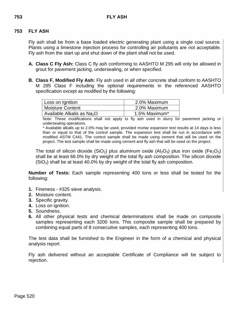
753 FLY ASH
Page 520
753 FLY ASH Fly ash shall be from a base loaded electric generating plant using a single coal source. Plants using a limestone injection process for controlling air pollutants are not acceptable. Fly ash from the start up and shut down of the plant shall not be used. A. Class C Fly Ash: Class C fly ash conforming to AASHTO M 295 will only be allowed in
grout for pavement jacking, undersealing, or when specified. B. Class F, Modified Fly Ash: Fly ash used in all other concrete shall conform to AASHTO
M 295 Class F including the optional requirements in the referenced AASHTO specification except as modified by the following:
Loss on Ignition 2.0% Maximum Moisture Content 2.0% Maximum Available Alkalis as Na2O 1.5% Maximum*
Note: These modifications shall not apply to fly ash used in slurry for pavement jacking or undersealing operations. * Available alkalis up to 2.0% may be used, provided mortar expansion test results at 14 days is less than or equal to that of the control sample. The expansion test shall be run in accordance with modified ASTM C441. The control sample shall be made using cement that will be used on the project. The test sample shall be made using cement and fly ash that will be used on the project.
The total of silicon dioxide (SiO2) plus aluminum oxide (Al2O3) plus iron oxide (Fe2O3) shall be at least 66.0% by dry weight of the total fly ash composition. The silicon dioxide (SiO2) shall be at least 40.0% by dry weight of the total fly ash composition.
Number of Tests: Each sample representing 400 tons or less shall be tested for the following: 1. Fineness - #325 sieve analysis. 2. Moisture content. 3. Specific gravity. 4. Loss on ignition. 5. Soundness. 6. All other physical tests and chemical determinations shall be made on composite
samples representing each 3200 tons. This composite sample shall be prepared by combining equal parts of 8 consecutive samples, each representing 400 tons.
The test data shall be furnished to the Engineer in the form of a chemical and physical analysis report. Fly ash delivered without an acceptable Certificate of Compliance will be subject to rejection.
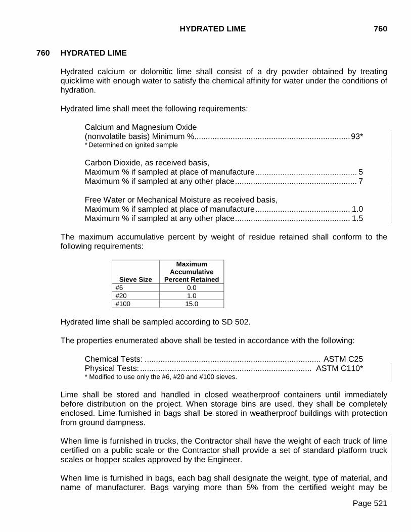
HYDRATED LIME 760
Page 521
760 HYDRATED LIME Hydrated calcium or dolomitic lime shall consist of a dry powder obtained by treating quicklime with enough water to satisfy the chemical affinity for water under the conditions of hydration. Hydrated lime shall meet the following requirements:
Calcium and Magnesium Oxide (nonvolatile basis) Minimum % ..................................................................... 93* * Determined on ignited sample Carbon Dioxide, as received basis, Maximum % if sampled at place of manufacture ............................................. 5 Maximum % if sampled at any other place ...................................................... 7 Free Water or Mechanical Moisture as received basis, Maximum % if sampled at place of manufacture .......................................... 1.0 Maximum % if sampled at any other place ................................................... 1.5
The maximum accumulative percent by weight of residue retained shall conform to the following requirements:
Sieve Size
Maximum Accumulative
Percent Retained #6 0.0 #20 1.0 #100 15.0
Hydrated lime shall be sampled according to SD 502. The properties enumerated above shall be tested in accordance with the following:
Chemical Tests: .............................................................................. ASTM C25 Physical Tests: ............................................................................ ASTM C110*
* Modified to use only the #6, #20 and #100 sieves.
Lime shall be stored and handled in closed weatherproof containers until immediately before distribution on the project. When storage bins are used, they shall be completely enclosed. Lime furnished in bags shall be stored in weatherproof buildings with protection from ground dampness. When lime is furnished in trucks, the Contractor shall have the weight of each truck of lime certified on a public scale or the Contractor shall provide a set of standard platform truck scales or hopper scales approved by the Engineer. When lime is furnished in bags, each bag shall designate the weight, type of material, and name of manufacturer. Bags varying more than 5% from the certified weight may be
760 HYDRATED LIME
Page 522
rejected. The average weight of bags in any shipment, as shown by weighing 50 bags taken at random, shall not be less than the manufacturer's certified weight.
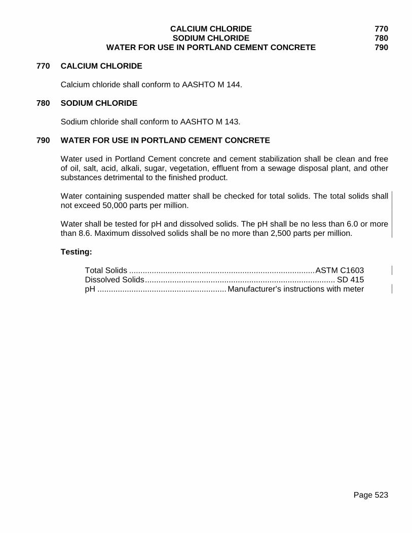
CALCIUM CHLORIDE 770 SODIUM CHLORIDE 780 WATER FOR USE IN PORTLAND CEMENT CONCRETE 790
Page 523
770 CALCIUM CHLORIDE
Calcium chloride shall conform to AASHTO M 144.
780 SODIUM CHLORIDE Sodium chloride shall conform to AASHTO M 143.
790 WATER FOR USE IN PORTLAND CEMENT CONCRETE Water used in Portland Cement concrete and cement stabilization shall be clean and free of oil, salt, acid, alkali, sugar, vegetation, effluent from a sewage disposal plant, and other substances detrimental to the finished product. Water containing suspended matter shall be checked for total solids. The total solids shall not exceed 50,000 parts per million. Water shall be tested for pH and dissolved solids. The pH shall be no less than 6.0 or more than 8.6. Maximum dissolved solids shall be no more than 2,500 parts per million. Testing:
Total Solids .................................................................................. ASTM C1603 Dissolved Solids .................................................................................... SD 415 pH ......................................................... Manufacturer’s instructions with meter
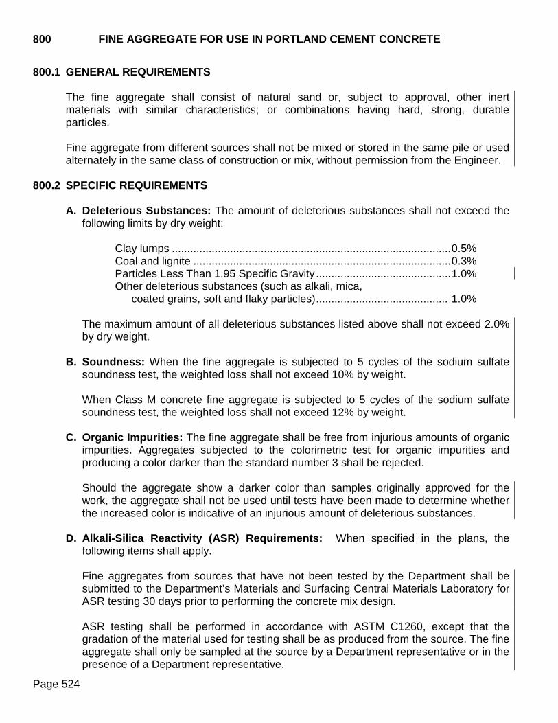
800 FINE AGGREGATE FOR USE IN PORTLAND CEMENT CONCRETE
Page 524
800.1 GENERAL REQUIREMENTS
The fine aggregate shall consist of natural sand or, subject to approval, other inert materials with similar characteristics; or combinations having hard, strong, durable particles. Fine aggregate from different sources shall not be mixed or stored in the same pile or used alternately in the same class of construction or mix, without permission from the Engineer.
800.2 SPECIFIC REQUIREMENTS
A. Deleterious Substances: The amount of deleterious substances shall not exceed the following limits by dry weight:
Clay lumps ........................................................................................... 0.5% Coal and lignite .................................................................................... 0.3% Particles Less Than 1.95 Specific Gravity ............................................ 1.0% Other deleterious substances (such as alkali, mica,
coated grains, soft and flaky particles) ........................................... 1.0%
The maximum amount of all deleterious substances listed above shall not exceed 2.0% by dry weight.
B. Soundness: When the fine aggregate is subjected to 5 cycles of the sodium sulfate
soundness test, the weighted loss shall not exceed 10% by weight.
When Class M concrete fine aggregate is subjected to 5 cycles of the sodium sulfate soundness test, the weighted loss shall not exceed 12% by weight.
C. Organic Impurities: The fine aggregate shall be free from injurious amounts of organic
impurities. Aggregates subjected to the colorimetric test for organic impurities and producing a color darker than the standard number 3 shall be rejected.
Should the aggregate show a darker color than samples originally approved for the work, the aggregate shall not be used until tests have been made to determine whether the increased color is indicative of an injurious amount of deleterious substances.
D. Alkali-Silica Reactivity (ASR) Requirements: When specified in the plans, the
following items shall apply.
Fine aggregates from sources that have not been tested by the Department shall be submitted to the Department’s Materials and Surfacing Central Materials Laboratory for ASR testing 30 days prior to performing the concrete mix design. ASR testing shall be performed in accordance with ASTM C1260, except that the gradation of the material used for testing shall be as produced from the source. The fine aggregate shall only be sampled at the source by a Department representative or in the presence of a Department representative.
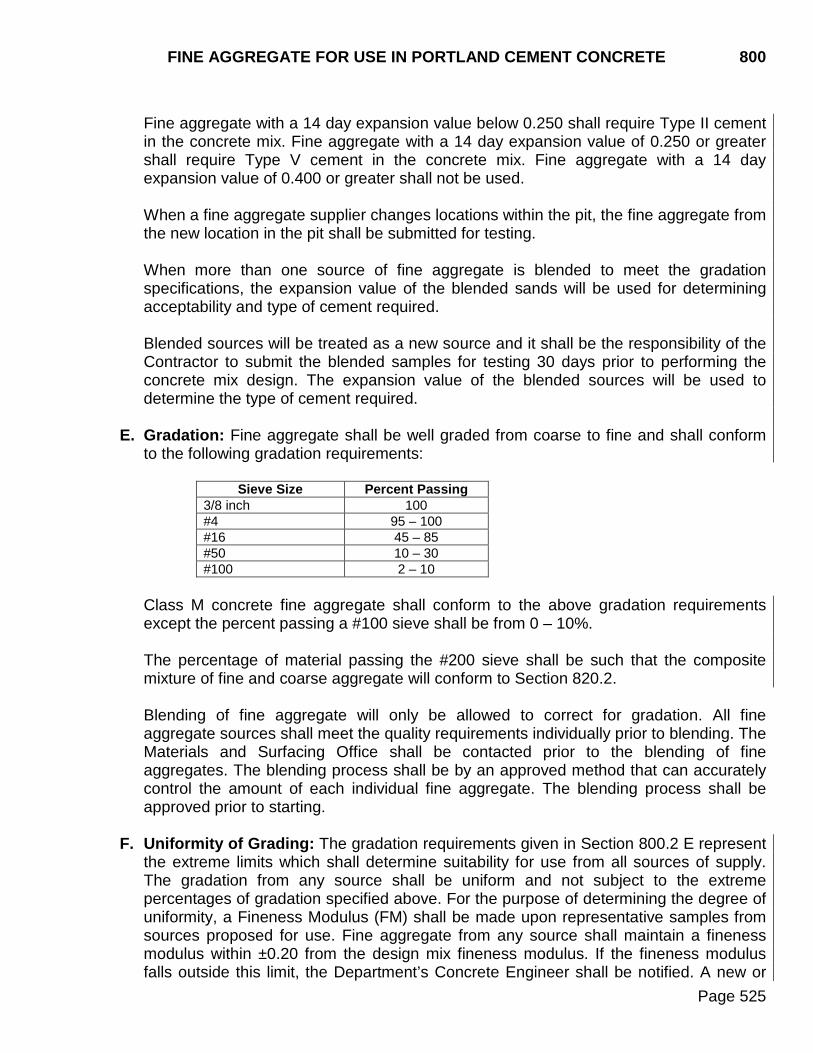
FINE AGGREGATE FOR USE IN PORTLAND CEMENT CONCRETE 800
Page 525
Fine aggregate with a 14 day expansion value below 0.250 shall require Type II cement in the concrete mix. Fine aggregate with a 14 day expansion value of 0.250 or greater shall require Type V cement in the concrete mix. Fine aggregate with a 14 day expansion value of 0.400 or greater shall not be used. When a fine aggregate supplier changes locations within the pit, the fine aggregate from the new location in the pit shall be submitted for testing.
When more than one source of fine aggregate is blended to meet the gradation specifications, the expansion value of the blended sands will be used for determining acceptability and type of cement required. Blended sources will be treated as a new source and it shall be the responsibility of the Contractor to submit the blended samples for testing 30 days prior to performing the concrete mix design. The expansion value of the blended sources will be used to determine the type of cement required.
E. Gradation: Fine aggregate shall be well graded from coarse to fine and shall conform
to the following gradation requirements:
Sieve Size Percent Passing 3/8 inch 100 #4 95 – 100 #16 45 – 85 #50 10 – 30 #100 2 – 10
Class M concrete fine aggregate shall conform to the above gradation requirements except the percent passing a #100 sieve shall be from 0 – 10%.
The percentage of material passing the #200 sieve shall be such that the composite mixture of fine and coarse aggregate will conform to Section 820.2.
Blending of fine aggregate will only be allowed to correct for gradation. All fine aggregate sources shall meet the quality requirements individually prior to blending. The Materials and Surfacing Office shall be contacted prior to the blending of fine aggregates. The blending process shall be by an approved method that can accurately control the amount of each individual fine aggregate. The blending process shall be approved prior to starting.
F. Uniformity of Grading: The gradation requirements given in Section 800.2 E represent
the extreme limits which shall determine suitability for use from all sources of supply. The gradation from any source shall be uniform and not subject to the extreme percentages of gradation specified above. For the purpose of determining the degree of uniformity, a Fineness Modulus (FM) shall be made upon representative samples from sources proposed for use. Fine aggregate from any source shall maintain a fineness modulus within ±0.20 from the design mix fineness modulus. If the fineness modulus falls outside this limit, the Department’s Concrete Engineer shall be notified. A new or
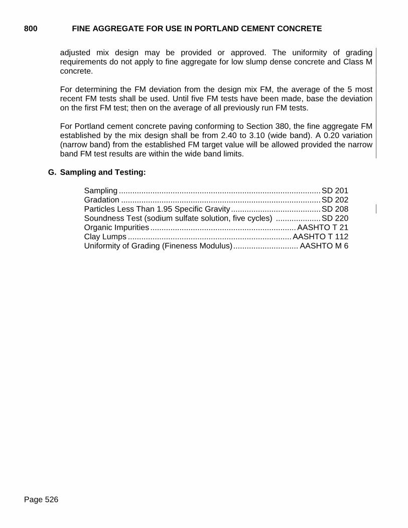
800 FINE AGGREGATE FOR USE IN PORTLAND CEMENT CONCRETE
Page 526
adjusted mix design may be provided or approved. The uniformity of grading requirements do not apply to fine aggregate for low slump dense concrete and Class M concrete. For determining the FM deviation from the design mix FM, the average of the 5 most recent FM tests shall be used. Until five FM tests have been made, base the deviation on the first FM test; then on the average of all previously run FM tests. For Portland cement concrete paving conforming to Section 380, the fine aggregate FM established by the mix design shall be from 2.40 to 3.10 (wide band). A 0.20 variation (narrow band) from the established FM target value will be allowed provided the narrow band FM test results are within the wide band limits.
G. Sampling and Testing:
Sampling .......................................................................................... SD 201 Gradation ......................................................................................... SD 202 Particles Less Than 1.95 Specific Gravity ........................................ SD 208 Soundness Test (sodium sulfate solution, five cycles) .................... SD 220 Organic Impurities ................................................................. AASHTO T 21 Clay Lumps ......................................................................... AASHTO T 112 Uniformity of Grading (Fineness Modulus) ............................. AASHTO M 6
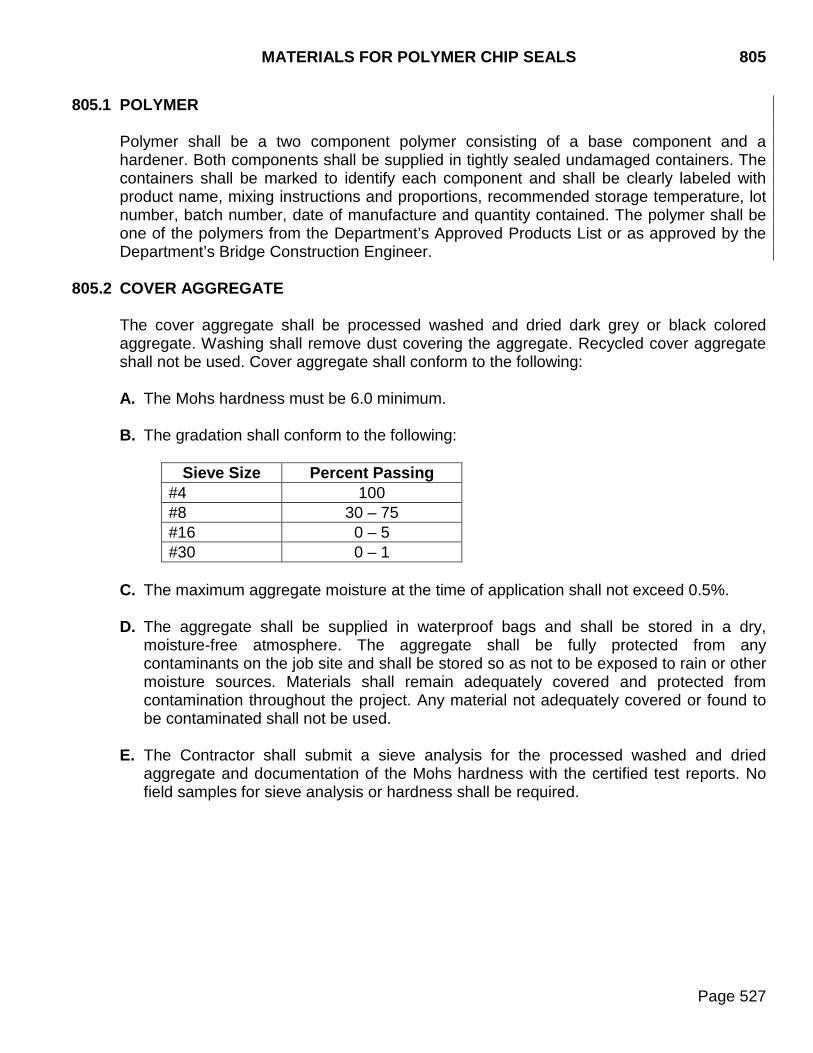
MATERIALS FOR POLYMER CHIP SEALS 805
Page 527
805.1 POLYMER
Polymer shall be a two component polymer consisting of a base component and a hardener. Both components shall be supplied in tightly sealed undamaged containers. The containers shall be marked to identify each component and shall be clearly labeled with product name, mixing instructions and proportions, recommended storage temperature, lot number, batch number, date of manufacture and quantity contained. The polymer shall be one of the polymers from the Department’s Approved Products List or as approved by the Department’s Bridge Construction Engineer.
805.2 COVER AGGREGATE
The cover aggregate shall be processed washed and dried dark grey or black colored aggregate. Washing shall remove dust covering the aggregate. Recycled cover aggregate shall not be used. Cover aggregate shall conform to the following:
A. The Mohs hardness must be 6.0 minimum.
B. The gradation shall conform to the following:
Sieve Size Percent Passing
#4 100 #8 30 – 75 #16 0 – 5 #30 0 – 1
C. The maximum aggregate moisture at the time of application shall not exceed 0.5%.
D. The aggregate shall be supplied in waterproof bags and shall be stored in a dry,
moisture-free atmosphere. The aggregate shall be fully protected from any contaminants on the job site and shall be stored so as not to be exposed to rain or other moisture sources. Materials shall remain adequately covered and protected from contamination throughout the project. Any material not adequately covered or found to be contaminated shall not be used.
E. The Contractor shall submit a sieve analysis for the processed washed and dried aggregate and documentation of the Mohs hardness with the certified test reports. No field samples for sieve analysis or hardness shall be required.
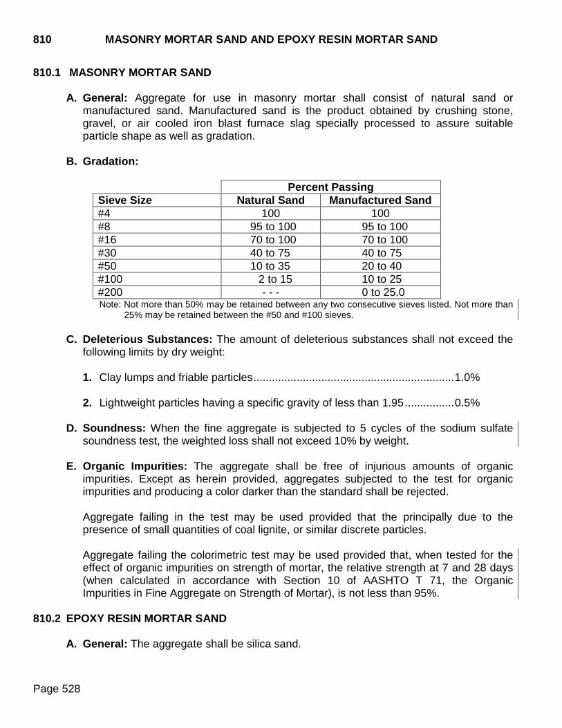
810 MASONRY MORTAR SAND AND EPOXY RESIN MORTAR SAND
Page 528
810.1 MASONRY MORTAR SAND
A. General: Aggregate for use in masonry mortar shall consist of natural sand or manufactured sand. Manufactured sand is the product obtained by crushing stone, gravel, or air cooled iron blast furnace slag specially processed to assure suitable particle shape as well as gradation.
B. Gradation:
Percent Passing Sieve Size Natural Sand Manufactured Sand #4 100 100 #8 95 to 100 95 to 100 #16 70 to 100 70 to 100 #30 40 to 75 40 to 75 #50 10 to 35 20 to 40 #100 2 to 15 10 to 25 #200 - - - 0 to 25.0 Note: Not more than 50% may be retained between any two consecutive sieves listed. Not more than
25% may be retained between the #50 and #100 sieves.
C. Deleterious Substances: The amount of deleterious substances shall not exceed the following limits by dry weight:
1. Clay lumps and friable particles ................................................................. 1.0%
2. Lightweight particles having a specific gravity of less than 1.95 ................ 0.5%
D. Soundness: When the fine aggregate is subjected to 5 cycles of the sodium sulfate
soundness test, the weighted loss shall not exceed 10% by weight.
E. Organic Impurities: The aggregate shall be free of injurious amounts of organic impurities. Except as herein provided, aggregates subjected to the test for organic impurities and producing a color darker than the standard shall be rejected.
Aggregate failing in the test may be used provided that the principally due to the presence of small quantities of coal lignite, or similar discrete particles.
Aggregate failing the colorimetric test may be used provided that, when tested for the effect of organic impurities on strength of mortar, the relative strength at 7 and 28 days (when calculated in accordance with Section 10 of AASHTO T 71, the Organic Impurities in Fine Aggregate on Strength of Mortar), is not less than 95%.
810.2 EPOXY RESIN MORTAR SAND
A. General: The aggregate shall be silica sand.

MASONRY MORTAR SAND AND EPOXY RESIN MORTAR SAND 810
Page 529
B. Gradation:
Sieve Size Percent Passing #8 100 #50 15 to 40 #100 0 to 10 #200 0 to 0.5
820 COARSE AGGREGATE FOR USE IN PORTLAND CEMENT CONCRETE
Page 530
820.1 GENERAL REQUIREMENTS
A. Coarse Aggregate for Concrete Pavement: The coarse aggregate shall consist of ledge rock. Coarse aggregate for continuously reinforced concrete pavement shall conform to Size #20. Coarse aggregate for all other PCC pavements shall conform to Size #15.
B. Coarse Aggregate Class A Concrete: The coarse aggregate shall consist of ledge
rock. Coarse aggregate for Class A concrete shall conform to the gradation requirements of Size #1, Size #15, or Size #20 as indicated on the mix design.
C. Coarse Aggregate for Bridge Deck Resurfacing: The coarse aggregate shall be
produced from ledge rock. The coarse aggregate shall conform to the gradation requirement of Size #3.
D. Coarse Aggregate for Class M Concrete: Coarse aggregate for Class M concrete
shall meet the gradation requirements for Size #1. If Class M concrete is cast at a commercial precast facility regularly producing other precast items under Section 560, the coarse aggregate shall conform to Section 820.1 E.
E. Coarse Aggregate for Prestressed and Precast Concrete: The coarse aggregate
shall be ledge rock. The aggregate size shall be consistent throughout the entire structure. Only one source shall be used to produce each aggregate size. Coarse aggregate for wet cast concrete shall meet the gradation requirements of Size #1 or Size #1A as indicated on the mix design. The gradation requirement shall not apply for dry cast concrete.
F. Coarse Aggregate for Spall Repair and Extender Aggregate for Packaged
Patching Mix Material including Dowel Bar Retrofit Patching Material: The coarse aggregate shall be ledge rock. Coarse aggregate for spall repair, except the coarse aggregate used in a packed patching material, shall meet the gradation requirements of Size #5. The gradation section does not apply to extender aggregate.
820.2 SPECIFIC REQUIREMENTS
A. Deleterious Substances: The amount of deleterious substances shall not exceed the following limits by dry weight:
Clay lumps ........................................................................................... 0.3% Shale and other materials having a specific gravity less than 1.95 ...... 1.0% Scratch hardness ................................................................................. 2.0% Other deleterious substances (such as alkali, mica,
coated grains, flaky particles, coal, lignite, and chocolate rock) ...... 2.0%
The maximum amount of deleterious substances listed above shall not exceed 2.0% by dry weight.

COARSE AGGREGATE FOR USE 820 IN PORTLAND CEMENT CONCRETE
Page 531
The deleterious substances in the coarse aggregate for Class M concrete shall not exceed the following limits:
Clay lumps ........................................................................................... 0.5% Shale and other materials having a specific gravity less than 1.95 ...... 1.0% Scratch hardness ................................................................................. 2.0% Other deleterious materials (such as alkali, mica,
coated grains, flaky particles, coal, lignite, and chocolate rock) ..... 3.0%
The maximum amount of all deleterious material shall not exceed 3.0% by dry weight.
B. Percentage of Wear: The percentage of wear, LA abrasion test, shall not be more than 40% by weight.
C. Soundness: When the coarse aggregate is subjected to 5 cycles of the sodium sulfate
soundness test, the weighted loss shall not exceed 10% by weight. When Class M coarse aggregate is subjected to 5 cycles of the sodium sulfate soundness test, the weighted loss shall not exceed 12% by weight. .
D. Gradation: Each size of coarse aggregate shall conform to the gradation requirements specified in the following table:
PERCENTAGE BY DRY WEIGHT PASSING SIEVE
Size #
Nominal Size Square Openings 2 inch 1½ inch 1 inch ¾ inch ½ inch 3/8 inch #4 #8
1 1 inch to #8 100 95-100 25-60 0-10 0-5*1
1A 3/4 inch to #8 100 90-100 20-55 0-10 0-5*1
3 3/4 inch to #8 100 97-100 40-90 5-20 0-5*1
5 1/2 inch to #8 100 90-100 40-70 0-20 0-5*1
15 1½ inch to #8 100 98-100 70-90 27-53 2-20 0-6*1
20 2 inch to #8 100 97-100 66-85 45-70 15-40 1-20 0-5*1
*1 The combined mixture of fine and coarse aggregate shall be such that not more than 1.5% passes the #200 sieve. This limit shall not be more than 2.5% for Class M concrete.
E. Flat and Elongated Particles: The maximum amount of flat and elongated particles for
the coarse aggregate shall not exceed 10%. Flat and elongated particles are defined as those particles with a ratio of maximum to minimum dimension greater than 5:1
F. Sampling and Testing:
Sampling ...................................................................................... SD 201 Gradation ..................................................................................... SD 202 Clay lumps ................................................................................... AASHTO T 112 Particles Less Than 1.95 Specific Gravity .................................... SD 214

820 COARSE AGGREGATE FOR USE IN PORTLAND CEMENT CONCRETE
Page 532
Scratch Hardness ......................................................................... SD 218*
Flat and Elongated Particles ........................................................ SD 212 Chocolate Rock ............................................................................ SD 216*
LA Abrasion .................................................................................. SD 204 Soundness Test (sodium sulfate solution, five cycles) ................. SD 220 Material Finer than #200 Sieve .................................................... SD 206 * Not required for ledge rock
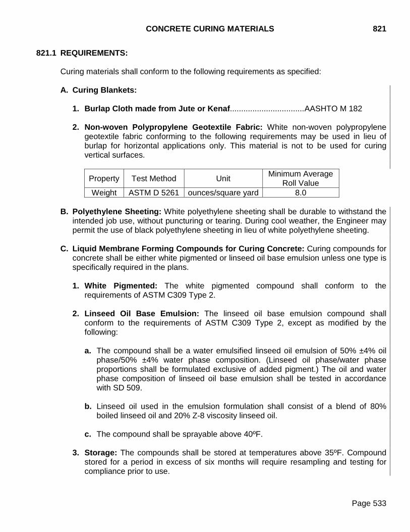
CONCRETE CURING MATERIALS 821
Page 533
821.1 REQUIREMENTS: Curing materials shall conform to the following requirements as specified:
A. Curing Blankets:
1. Burlap Cloth made from Jute or Kenaf................................. AASHTO M 182 2. Non-woven Polypropylene Geotextile Fabric: White non-woven polypropylene
geotextile fabric conforming to the following requirements may be used in lieu of burlap for horizontal applications only. This material is not to be used for curing vertical surfaces.
Property Test Method Unit Minimum Average Roll Value
Weight ASTM D 5261 ounces/square yard 8.0
B. Polyethylene Sheeting: White polyethylene sheeting shall be durable to withstand the intended job use, without puncturing or tearing. During cool weather, the Engineer may permit the use of black polyethylene sheeting in lieu of white polyethylene sheeting.
C. Liquid Membrane Forming Compounds for Curing Concrete: Curing compounds for
concrete shall be either white pigmented or linseed oil base emulsion unless one type is specifically required in the plans.
1. White Pigmented: The white pigmented compound shall conform to the
requirements of ASTM C309 Type 2. 2. Linseed Oil Base Emulsion: The linseed oil base emulsion compound shall
conform to the requirements of ASTM C309 Type 2, except as modified by the following:
a. The compound shall be a water emulsified linseed oil emulsion of 50% ±4% oil
phase/50% ±4% water phase composition. (Linseed oil phase/water phase proportions shall be formulated exclusive of added pigment.) The oil and water phase composition of linseed oil base emulsion shall be tested in accordance with SD 509.
b. Linseed oil used in the emulsion formulation shall consist of a blend of 80%
boiled linseed oil and 20% Z-8 viscosity linseed oil.
c. The compound shall be sprayable above 40ºF.
3. Storage: The compounds shall be stored at temperatures above 35ºF. Compound stored for a period in excess of six months will require resampling and testing for compliance prior to use.

821 CONCRETE CURING MATERIALS
Page 534
4. Sampling and Testing: The Department will test the liquid membrane forming compounds for water retention in accordance with AASHTO T 155 at an application rate of 1 gallon per 200 ft2.
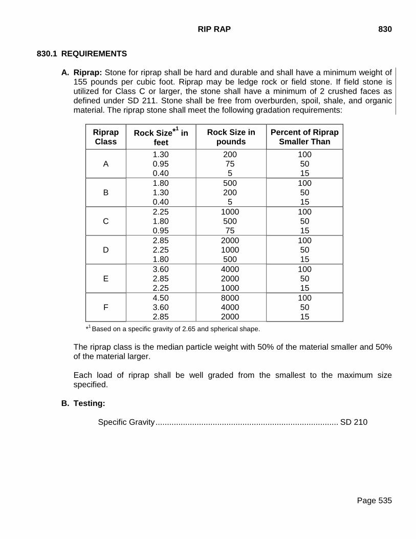
RIP RAP 830
Page 535
830.1 REQUIREMENTS
A. Riprap: Stone for riprap shall be hard and durable and shall have a minimum weight of 155 pounds per cubic foot. Riprap may be ledge rock or field stone. If field stone is utilized for Class C or larger, the stone shall have a minimum of 2 crushed faces as defined under SD 211. Stone shall be free from overburden, spoil, shale, and organic material. The riprap stone shall meet the following gradation requirements:
Riprap Class
Rock Size*1 in feet
Rock Size in pounds
Percent of Riprap Smaller Than
A 1.30 0.95 0.40
200 75 5
100 50 15
B 1.80 1.30 0.40
500 200
5
100 50 15
C 2.25 1.80 0.95
1000 500 75
100 50 15
D 2.85 2.25 1.80
2000 1000 500
100 50 15
E 3.60 2.85 2.25
4000 2000 1000
100 50 15
F 4.50 3.60 2.85
8000 4000 2000
100 50 15
*1 Based on a specific gravity of 2.65 and spherical shape.
The riprap class is the median particle weight with 50% of the material smaller and 50% of the material larger. Each load of riprap shall be well graded from the smallest to the maximum size specified.
B. Testing:
Specific Gravity ................................................................................ SD 210
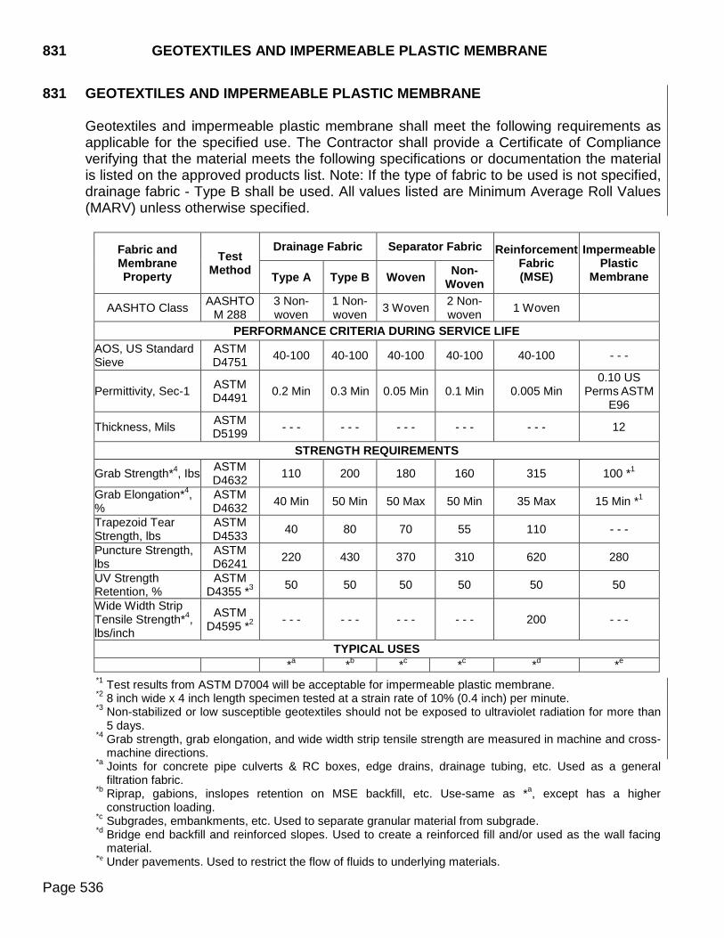
831 GEOTEXTILES AND IMPERMEABLE PLASTIC MEMBRANE
Page 536
831 GEOTEXTILES AND IMPERMEABLE PLASTIC MEMBRANE
Geotextiles and impermeable plastic membrane shall meet the following requirements as applicable for the specified use. The Contractor shall provide a Certificate of Compliance verifying that the material meets the following specifications or documentation the material is listed on the approved products list. Note: If the type of fabric to be used is not specified, drainage fabric - Type B shall be used. All values listed are Minimum Average Roll Values (MARV) unless otherwise specified.
Fabric and Membrane Property
Test Method
Drainage Fabric Separator Fabric Reinforcement Fabric (MSE)
Impermeable Plastic
Membrane Type A Type B Woven Non-Woven
AASHTO Class AASHTO M 288
3 Non-woven
1 Non-woven 3 Woven 2 Non-
woven 1 Woven
PERFORMANCE CRITERIA DURING SERVICE LIFE AOS, US Standard Sieve
ASTM D4751 40-100 40-100 40-100 40-100 40-100 - - -
Permittivity, Sec-1 ASTM D4491 0.2 Min 0.3 Min 0.05 Min 0.1 Min 0.005 Min
0.10 US Perms ASTM
E96
Thickness, Mils ASTM D5199 - - - - - - - - - - - - - - - 12
STRENGTH REQUIREMENTS
Grab Strength*4, Ibs ASTM D4632 110 200 180 160 315 100 *1
Grab Elongation*4, %
ASTM D4632 40 Min 50 Min 50 Max 50 Min 35 Max 15 Min *1
Trapezoid Tear Strength, lbs
ASTM D4533 40 80 70 55 110 - - -
Puncture Strength, lbs
ASTM D6241 220 430 370 310 620 280
UV Strength Retention, %
ASTM D4355 *3 50 50 50 50 50 50
Wide Width Strip Tensile Strength*4, lbs/inch
ASTM D4595 *2 - - - - - - - - - - - - 200 - - -
TYPICAL USES *a *b *c *c *d *e
*1 Test results from ASTM D7004 will be acceptable for impermeable plastic membrane. *2 8 inch wide x 4 inch length specimen tested at a strain rate of 10% (0.4 inch) per minute. *3 Non-stabilized or low susceptible geotextiles should not be exposed to ultraviolet radiation for more than
5 days. *4 Grab strength, grab elongation, and wide width strip tensile strength are measured in machine and cross-
machine directions. *a Joints for concrete pipe culverts & RC boxes, edge drains, drainage tubing, etc. Used as a general
filtration fabric. *b Riprap, gabions, inslopes retention on MSE backfill, etc. Use-same as *a, except has a higher
construction loading. *c Subgrades, embankments, etc. Used to separate granular material from subgrade. *d Bridge end backfill and reinforced slopes. Used to create a reinforced fill and/or used as the wall facing
material. *e Under pavements. Used to restrict the flow of fluids to underlying materials.
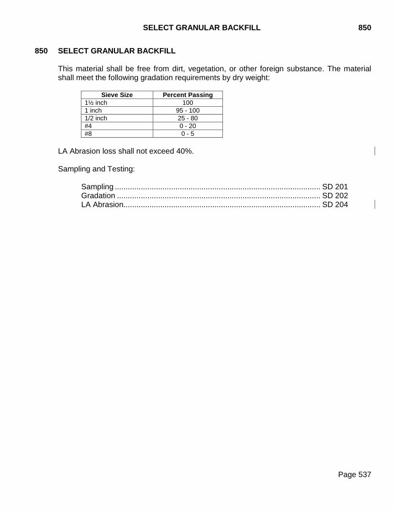
SELECT GRANULAR BACKFILL 850
Page 537
850 SELECT GRANULAR BACKFILL
This material shall be free from dirt, vegetation, or other foreign substance. The material shall meet the following gradation requirements by dry weight:
Sieve Size Percent Passing
1½ inch 100 1 inch 95 - 100 1/2 inch 25 - 80 #4 0 - 20 #8 0 - 5
LA Abrasion loss shall not exceed 40%. Sampling and Testing:
Sampling ............................................................................................... SD 201 Gradation .............................................................................................. SD 202 LA Abrasion ........................................................................................... SD 204

860 PREFORMED EXPANSION JOINT FILLER FOR CONCRETE
Page 538
860.1 REQUIREMENTS
Preformed expansion joint filler for concrete shall conform to the requirements of AASHTO M 213.
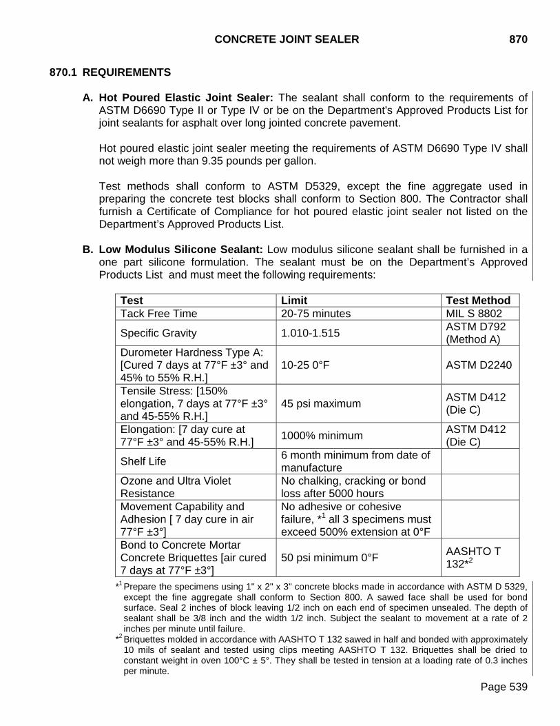
CONCRETE JOINT SEALER 870
Page 539
870.1 REQUIREMENTS
A. Hot Poured Elastic Joint Sealer: The sealant shall conform to the requirements of ASTM D6690 Type II or Type IV or be on the Department's Approved Products List for joint sealants for asphalt over long jointed concrete pavement. Hot poured elastic joint sealer meeting the requirements of ASTM D6690 Type IV shall not weigh more than 9.35 pounds per gallon.
Test methods shall conform to ASTM D5329, except the fine aggregate used in preparing the concrete test blocks shall conform to Section 800. The Contractor shall furnish a Certificate of Compliance for hot poured elastic joint sealer not listed on the Department’s Approved Products List.
B. Low Modulus Silicone Sealant: Low modulus silicone sealant shall be furnished in a
one part silicone formulation. The sealant must be on the Department’s Approved Products List and must meet the following requirements:
Test Limit Test Method Tack Free Time 20-75 minutes MIL S 8802
Specific Gravity 1.010-1.515 ASTM D792 (Method A)
Durometer Hardness Type A: [Cured 7 days at 77°F ±3° and 45% to 55% R.H.]
10-25 0°F ASTM D2240
Tensile Stress: [150% elongation, 7 days at 77°F ±3° and 45-55% R.H.]
45 psi maximum ASTM D412 (Die C)
Elongation: [7 day cure at 77°F ±3° and 45-55% R.H.] 1000% minimum ASTM D412
(Die C)
Shelf Life 6 month minimum from date of manufacture
Ozone and Ultra Violet Resistance
No chalking, cracking or bond loss after 5000 hours
Movement Capability and Adhesion [ 7 day cure in air 77°F ±3°]
No adhesive or cohesive failure, *1 all 3 specimens must exceed 500% extension at 0°F
Bond to Concrete Mortar Concrete Briquettes [air cured 7 days at 77°F ±3°]
50 psi minimum 0°F AASHTO T 132*2
*1 Prepare the specimens using 1" x 2" x 3" concrete blocks made in accordance with ASTM D 5329, except the fine aggregate shall conform to Section 800. A sawed face shall be used for bond surface. Seal 2 inches of block leaving 1/2 inch on each end of specimen unsealed. The depth of sealant shall be 3/8 inch and the width 1/2 inch. Subject the sealant to movement at a rate of 2 inches per minute until failure.
*2 Briquettes molded in accordance with AASHTO T 132 sawed in half and bonded with approximately 10 mils of sealant and tested using clips meeting AASHTO T 132. Briquettes shall be dried to constant weight in oven 100°C ± 5°. They shall be tested in tension at a loading rate of 0.3 inches per minute.
870 CONCRETE JOINT SEALER
Page 540
The backer rod shall be a non-moisture absorbing, closed cell, resilient material meeting the requirements of ASTM D5249 approximately 25% larger in diameter than the width of the joint to be sealed. The backer rod shall be compatible with the sealant and no bond or reaction shall occur between the rod and the sealant.
ASPHALT CONCRETE CRACK SEALANT (New Section) 871
Page 541
871 ASPHALT CONCRETE CRACK SEALANT
The sealant shall conform to the requirements of ASTM D6690 Type IV. The sealant material shall not weigh more than 9.35 pounds per gallon. Only products that meet the above requirements and have performed satisfactorily based on Department analysis may be used. A listing of acceptable products meeting ASTM D6690 Type IV requirements may be obtained from the Department's Approved Products List. Products on the Department’s Approved Products List for joint sealant for asphalt over long jointed concrete pavement may also be used. The blocking medium shall be an inert, compressible material which is compatible with the sealant.
879 BLOTTING SAND
Page 542
879.1 REQUIREMENTS
A. Sand for Prime: Sand for prime shall meet the following requirements:
Percent passing 3/8 inch sieve .................................................................... 100 Percent passing #40 sieve ......................................................................... 0-60 Percent passing #200 sieve..................................................................... 0-20.0 Plasticity Index ...................................................................................... 12 Max.
B. Sand for Flush Seal and Sand for Fog Seal: Sand for flush seal and sand for fog seal
shall meet the following requirements:
Percent passing 3/8 inch sieve .................................................................... 100 Percent passing #8 sieve ........................................................................... 0-95 Percent passing #40 sieve ......................................................................... 0-70 Percent passing #200 sieve..................................................................... 0-12.0 Plasticity Index ........................................................................................ 6 Max.
The sand shall be free from dirt and vegetation. Crushing is not required. Blow sand is not considered satisfactory material.
C. Sampling and Testing:
Sampling ............................................................................................... SD 201 Gradation ............................................................................................... SD 202 Plasticity Index ....................................................................................... SD 207
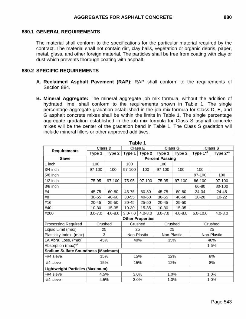
AGGREGATES FOR ASPHALT CONCRETE 880
Page 543
880.1 GENERAL REQUIREMENTS
The material shall conform to the specifications for the particular material required by the contract. The material shall not contain dirt, clay balls, vegetation or organic debris, paper, metal, glass, and other foreign material. The particles shall be free from coating with clay or dust which prevents thorough coating with asphalt.
880.2 SPECIFIC REQUIREMENTS
A. Reclaimed Asphalt Pavement (RAP): RAP shall conform to the requirements of Section 884.
B. Mineral Aggregate: The mineral aggregate job mix formula, without the addition of
hydrated lime, shall conform to the requirements shown in Table 1. The single percentage aggregate gradation established in the job mix formula for Class D, E, and G asphalt concrete mixes shall be within the limits in Table 1. The single percentage aggregate gradation established in the job mix formula for Class S asphalt concrete mixes will be the center of the gradation band in Table 1. The Class S gradation will include mineral fillers or other approved additives.
Table 1
Requirements Class D Class E Class G Class S Type 1 Type 2 Type 1 Type 2 Type 1 Type 2 Type 1*1 Type 2*1
Sieve Percent Passing 1 inch 100 100 100 3/4 inch 97-100 100 97-100 100 97-100 100 100 5/8 inch 97-100 100 1/2 inch 75-95 97-100 75-95 97-100 75-95 97-100 86-100 97-100 3/8 inch 66-80 80-100 #4 45-75 60-80 45-75 60-80 45-75 60-80 24-34 24-45 #8 30-55 40-60 30-55 40-60 30-55 40-60 10-20 10-22 #16 20-45 25-50 20-45 25-50 20-45 25-50 #40 10-30 15-35 10-30 15-35 10-30 15-35 #200 3.0-7.0 4.0-8.0 3.0-7.0 4.0-8.0 3.0-7.0 4.0-8.0 6.0-10.0 4.0-8.0
Other Properties Processing Required Crushed Crushed Crushed Crushed Liquid Limit (max) 25 25 25 25 Plasticity Index, (max) 3 Non-Plastic Non-Plastic Non-Plastic LA Abra. Loss, (max) 45% 40% 35% 40% Absorption (max)*2 1.5% Sodium Sulfate Soundness (Maximum) +#4 sieve 15% 15% 12% 8% -#4 sieve 15% 15% 12% 8% Lightweight Particles (Maximum) +#4 sieve 4.5% 3.0% 1.0% 1.0% -#4 sieve 4.5% 3.0% 1.0% 1.0%
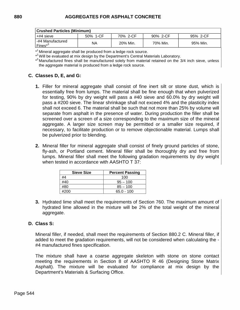
880 AGGREGATES FOR ASPHALT CONCRETE
Page 544
Crushed Particles (Minimum) +#4 sieve 50% 1-CF 70% 2-CF 90% 2-CF 95% 2-CF -#4 Manufactured Fines*3 NA 20% Min. 70% Min. 95% Min.
*1 Mineral aggregate shall be produced from a ledge rock source. *2 Will be evaluated at mix design by the Department’s Central Materials Laboratory. *3 Manufactured fines shall be manufactured solely from material retained on the 3/4 inch sieve, unless
the aggregate material is produced from a ledge rock source.
C. Classes D, E, and G:
1. Filler for mineral aggregate shall consist of fine inert silt or stone dust, which is essentially free from lumps. The material shall be fine enough that when pulverized for testing, 90% by dry weight will pass a #40 sieve and 60.0% by dry weight will pass a #200 sieve. The linear shrinkage shall not exceed 4% and the plasticity index shall not exceed 6. The material shall be such that not more than 25% by volume will separate from asphalt in the presence of water. During production the filler shall be screened over a screen of a size corresponding to the maximum size of the mineral aggregate. A larger size screen may be permitted or a smaller size required, if necessary, to facilitate production or to remove objectionable material. Lumps shall be pulverized prior to blending.
2. Mineral filler for mineral aggregate shall consist of finely ground particles of stone,
fly-ash, or Portland cement. Mineral filler shall be thoroughly dry and free from lumps. Mineral filler shall meet the following gradation requirements by dry weight when tested in accordance with AASHTO T 37:
Sieve Size Percent Passing
#4 100 #40 95 – 100 #80 85 – 100 #200 65.0 - 100
3. Hydrated lime shall meet the requirements of Section 760. The maximum amount of
hydrated lime allowed in the mixture will be 2% of the total weight of the mineral aggregate.
D. Class S:
Mineral filler, if needed, shall meet the requirements of Section 880.2 C. Mineral filler, if added to meet the gradation requirements, will not be considered when calculating the -#4 manufactured fines specification. The mixture shall have a coarse aggregate skeleton with stone on stone contact meeting the requirements in Section 8 of AASHTO R 46 (Designing Stone Matrix Asphalt). The mixture will be evaluated for compliance at mix design by the Department’s Materials & Surfacing Office.
AGGREGATES FOR ASPHALT CONCRETE 880
Page 545
880.3 SAMPLING AND TESTING
Sampling ................................................................................................... SD 201 Gradation .................................................................................................... SD 202 Liquid Limit and Plasticity Index .................................................................. SD 207 LA Abrasion Test ........................................................................................ SD 204 Linear Shrinkage (Filler) ............................................................................. SD 303 Soundness Test (sodium sulfate solution, five cycles) ............................... SD 220 W.A.P. Test (Filler) ..................................................................................... SD 304 Crushed Particle Test ................................................................................. SD 211 Particles Less Than 1.95 Specific Gravity .................................. SD 208 & SD 214 Absorption .................................................................................................. SD 210
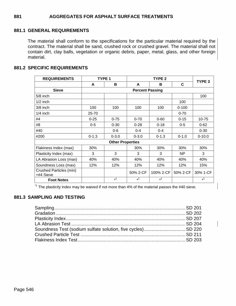
881 AGGREGATES FOR ASPHALT SURFACE TREATMENTS
Page 546
881.1 GENERAL REQUIREMENTS
The material shall conform to the specifications for the particular material required by the contract. The material shall be sand, crushed rock or crushed gravel. The material shall not contain dirt, clay balls, vegetation or organic debris, paper, metal, glass, and other foreign material.
881.2 SPECIFIC REQUIREMENTS
REQUIREMENTS TYPE 1 TYPE 2 TYPE 3
A B A B C Sieve Percent Passing
5/8 inch 100 1/2 inch 100 3/8 inch 100 100 100 100 0-100 1/4 inch 25-70 0-70 #4 0-25 0-75 0-70 0-60 0-15 10-75 #8 0-5 0-30 0-28 0-18 0-5 0-62 #40 0-6 0-4 0-4 0-30 #200 0-1.3 0-3.0 0-3.0 0-1.3 0-1.0 0-10.0
Other Properties Flakiness Index (max) 30% 30% 30% 30% 30% Plasticity Index (max) 3 3 3 3 NP 3 LA Abrasion Loss (max) 40% 40% 40% 40% 40% 40% Soundness Loss (max) 12% 12% 12% 12% 12% 15% Crushed Particles (min) +#4 Sieve 50% 2-CF 100% 2-CF 50% 2-CF 30% 1-CF
Foot Notes *1 *1 *1 *1 *1 The plasticity index may be waived if not more than 4% of the material passes the #40 sieve.
881.3 SAMPLING AND TESTING
Sampling ..................................................................................................... SD 201 Gradation .................................................................................................... SD 202 Plasticity Index ............................................................................................ SD 207 LA Abrasion Test ........................................................................................ SD 204 Soundness Test (sodium sulfate solution, five cycles) ................................ SD 220 Crushed Particle Test ................................................................................. SD 211 Flakiness Index Test ................................................................................... SD 203
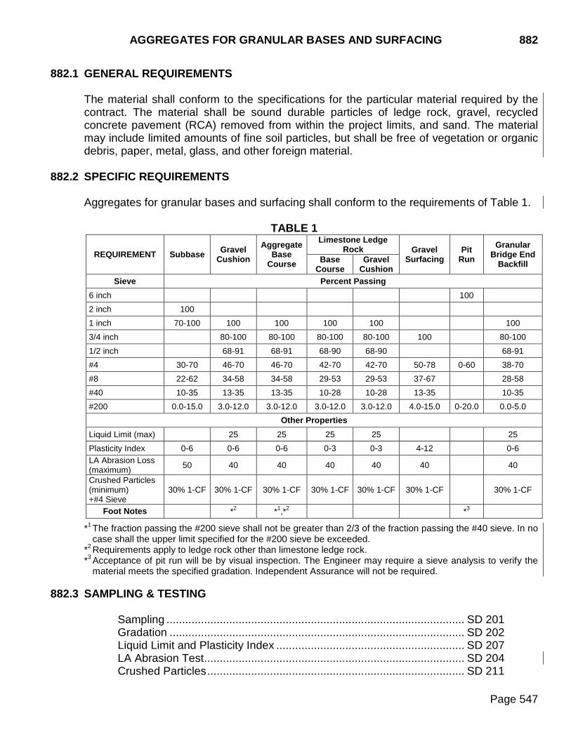
AGGREGATES FOR GRANULAR BASES AND SURFACING 882
Page 547
882.1 GENERAL REQUIREMENTS
The material shall conform to the specifications for the particular material required by the contract. The material shall be sound durable particles of ledge rock, gravel, recycled concrete pavement (RCA) removed from within the project limits, and sand. The material may include limited amounts of fine soil particles, but shall be free of vegetation or organic debris, paper, metal, glass, and other foreign material.
882.2 SPECIFIC REQUIREMENTS
Aggregates for granular bases and surfacing shall conform to the requirements of Table 1.
TABLE 1
*1 The fraction passing the #200 sieve shall not be greater than 2/3 of the fraction passing the #40 sieve. In no case shall the upper limit specified for the #200 sieve be exceeded.
*2 Requirements apply to ledge rock other than limestone ledge rock. *3 Acceptance of pit run will be by visual inspection. The Engineer may require a sieve analysis to verify the
material meets the specified gradation. Independent Assurance will not be required. 882.3 SAMPLING & TESTING
Sampling ............................................................................................... SD 201 Gradation .............................................................................................. SD 202 Liquid Limit and Plasticity Index ............................................................ SD 207 LA Abrasion Test ................................................................................... SD 204 Crushed Particles .................................................................................. SD 211
REQUIREMENT Subbase Gravel Cushion
Aggregate Base
Course
Limestone Ledge Rock Gravel
Surfacing Pit
Run Granular
Bridge End Backfill Base
Course Gravel
Cushion Sieve Percent Passing
6 inch 100 2 inch 100 1 inch 70-100 100 100 100 100 100 3/4 inch 80-100 80-100 80-100 80-100 100 80-100
1/2 inch 68-91 68-91 68-90 68-90 68-91 #4 30-70 46-70 46-70 42-70 42-70 50-78 0-60 38-70 #8 22-62 34-58 34-58 29-53 29-53 37-67 28-58 #40 10-35 13-35 13-35 10-28 10-28 13-35 10-35 #200 0.0-15.0 3.0-12.0 3.0-12.0 3.0-12.0 3.0-12.0 4.0-15.0 0-20.0 0.0-5.0
Other Properties Liquid Limit (max) 25 25 25 25 25 Plasticity Index 0-6 0-6 0-6 0-3 0-3 4-12 0-6 LA Abrasion Loss (maximum) 50 40 40 40 40 40 40
Crushed Particles (minimum) +#4 Sieve
30% 1-CF 30% 1-CF 30% 1-CF 30% 1-CF 30% 1-CF 30% 1-CF 30% 1-CF
Foot Notes *2 *1,*2 *3
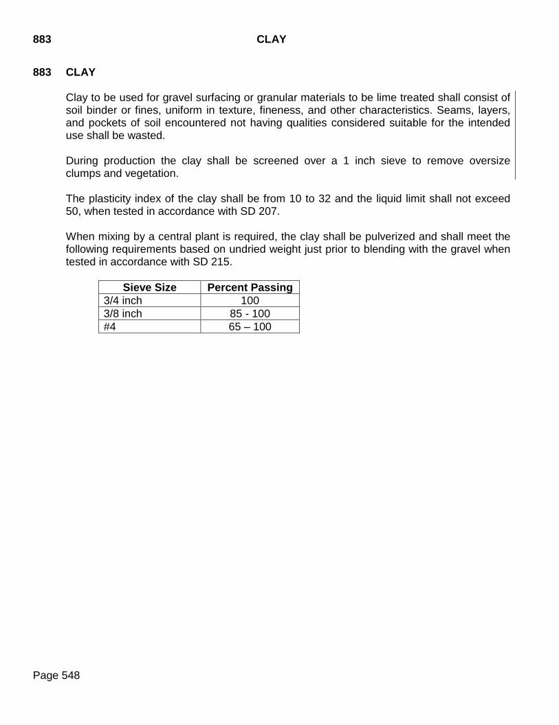
883 CLAY
Page 548
883 CLAY
Clay to be used for gravel surfacing or granular materials to be lime treated shall consist of soil binder or fines, uniform in texture, fineness, and other characteristics. Seams, layers, and pockets of soil encountered not having qualities considered suitable for the intended use shall be wasted.
During production the clay shall be screened over a 1 inch sieve to remove oversize clumps and vegetation.
The plasticity index of the clay shall be from 10 to 32 and the liquid limit shall not exceed 50, when tested in accordance with SD 207.
When mixing by a central plant is required, the clay shall be pulverized and shall meet the following requirements based on undried weight just prior to blending with the gravel when tested in accordance with SD 215.
Sieve Size Percent Passing 3/4 inch 100 3/8 inch 85 - 100 #4 65 – 100
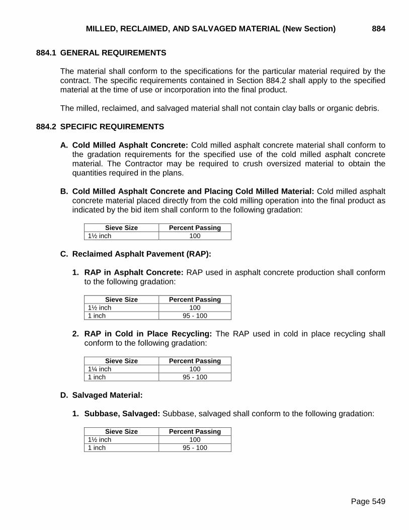
MILLED, RECLAIMED, AND SALVAGED MATERIAL (New Section) 884
Page 549
884.1 GENERAL REQUIREMENTS
The material shall conform to the specifications for the particular material required by the contract. The specific requirements contained in Section 884.2 shall apply to the specified material at the time of use or incorporation into the final product. The milled, reclaimed, and salvaged material shall not contain clay balls or organic debris.
884.2 SPECIFIC REQUIREMENTS
A. Cold Milled Asphalt Concrete: Cold milled asphalt concrete material shall conform to the gradation requirements for the specified use of the cold milled asphalt concrete material. The Contractor may be required to crush oversized material to obtain the quantities required in the plans.
B. Cold Milled Asphalt Concrete and Placing Cold Milled Material: Cold milled asphalt
concrete material placed directly from the cold milling operation into the final product as indicated by the bid item shall conform to the following gradation:
Sieve Size Percent Passing
1½ inch 100 C. Reclaimed Asphalt Pavement (RAP):
1. RAP in Asphalt Concrete: RAP used in asphalt concrete production shall conform to the following gradation:
Sieve Size Percent Passing
1½ inch 100 1 inch 95 - 100
2. RAP in Cold in Place Recycling: The RAP used in cold in place recycling shall
conform to the following gradation:
Sieve Size Percent Passing 1¼ inch 100 1 inch 95 - 100
D. Salvaged Material:
1. Subbase, Salvaged: Subbase, salvaged shall conform to the following gradation:
Sieve Size Percent Passing 1½ inch 100 1 inch 95 - 100
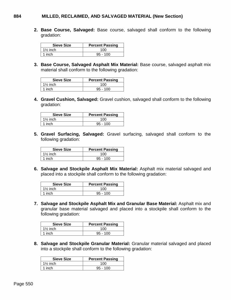
884 MILLED, RECLAIMED, AND SALVAGED MATERIAL (New Section)
Page 550
2. Base Course, Salvaged: Base course, salvaged shall conform to the following gradation:
Sieve Size Percent Passing
1½ inch 100 1 inch 95 - 100
3. Base Course, Salvaged Asphalt Mix Material: Base course, salvaged asphalt mix
material shall conform to the following gradation:
Sieve Size Percent Passing 1½ inch 100 1 inch 95 - 100
4. Gravel Cushion, Salvaged: Gravel cushion, salvaged shall conform to the following
gradation:
Sieve Size Percent Passing 1½ inch 100 1 inch 95 - 100
5. Gravel Surfacing, Salvaged: Gravel surfacing, salvaged shall conform to the
following gradation:
Sieve Size Percent Passing 1½ inch 100 1 inch 95 - 100
6. Salvage and Stockpile Asphalt Mix Material: Asphalt mix material salvaged and
placed into a stockpile shall conform to the following gradation:
Sieve Size Percent Passing 1½ inch 100 1 inch 95 - 100
7. Salvage and Stockpile Asphalt Mix and Granular Base Material: Asphalt mix and
granular base material salvaged and placed into a stockpile shall conform to the following gradation:
Sieve Size Percent Passing
1½ inch 100 1 inch 95 - 100
8. Salvage and Stockpile Granular Material: Granular material salvaged and placed
into a stockpile shall conform to the following gradation:
Sieve Size Percent Passing 1½ inch 100 1 inch 95 - 100
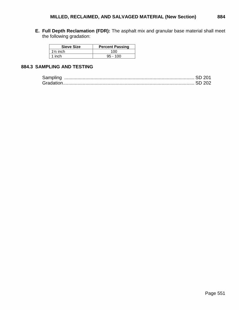
MILLED, RECLAIMED, AND SALVAGED MATERIAL (New Section) 884
Page 551
E. Full Depth Reclamation (FDR): The asphalt mix and granular base material shall meet the following gradation:
Sieve Size Percent Passing
1½ inch 100 1 inch 95 - 100
884.3 SAMPLING AND TESTING
Sampling ................................................................................................... SD 201 Gradation .................................................................................................... SD 202

890 ASPHALT MATERIAL
Page 552
890.1 GENERAL REQUIREMENTS
Transporting conveyances for asphalt material shall be free of contaminating material. A record of material hauled the previous load in truck transport tanks shall be furnished as a prerequisite to loading. A determination shall be made if the previously hauled material is compatible with the material to be loaded or if cleaning of the tank is required to prevent contamination. All sampling shall be performed in accordance with SD 301. If the material is to be used prior to testing by the Department, the asphalt material supplier shall furnish two copies of a Certificate of Compliance for each tank car, truck tank, or other individual conveyance. The Certificate of Compliance shall show all information contained on Form DOT-62 and a properly executed certification statement. Temperatures to provide kinematic viscosities of 300 centistokes and 150 centistokes for mixing application and 200 centistokes and 50 centistokes for spray application shall be furnished with the first load of each type of asphalt material delivered to the project on or along with the Certificate of Compliance. Upon presentation of a Certificate of Compliance, the Engineer may permit incorporation into the work the asphalt material covered by the certificate. Permission by the Engineer to use asphalt material shall not be construed as an acceptance of the material. Acceptance of asphalt material will be based on test results from the samples obtained. Asphalt material tested and accepted for use on a project and transferred by the Contractor to another project, may be accepted for use in the terminating project on the basis of the test results of the originating project. The Contractor must request and receive from the Engineer of the originating project, prior to transfer, a letter of transfer covering the material. (DOT-70)
890.2 SPECIFIC REQUIREMENTS
A. Rapid Curing Cut-back Asphalt shall conform to AASHTO M 81.
B. Medium Curing Cut-back Asphalt shall conform to AASHTO M 82.
C. Slow Curing Cut-back Asphalt shall conform to the following requirements.
1. The oil shall be uniform in appearance and consistency and shall show no foaming when heated to the application temperature. The residue of specified penetration shall be smooth and homogeneous in appearance.
2. The grade of liquid asphaltic material specified shall conform to the requirements
shown in the following table.
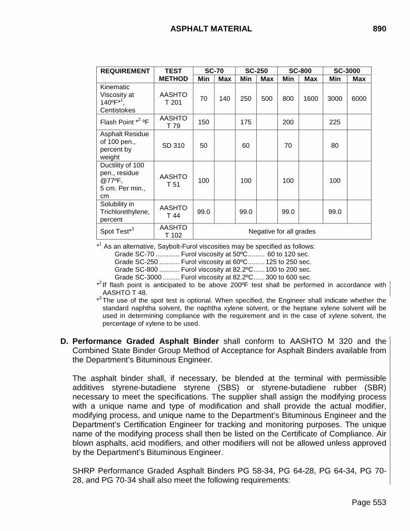
ASPHALT MATERIAL 890
Page 553
REQUIREMENT
TEST METHOD
SC-70 SC-250 SC-800 SC-3000 Min Max Min Max Min Max Min Max
Kinematic Viscosity at 140ºF*1, Centistokes
AASHTO T 201 70 140 250 500 800 1600 3000 6000
Flash Point *2 ºF AASHTO T 79 150 175 200 225
Asphalt Residue of 100 pen., percent by weight
SD 310 50 60 70 80
Ductility of 100 pen., residue @77ºF, 5 cm. Per min., cm
AASHTO T 51 100 100 100 100
Solubility in Trichlorethylene, percent
AASHTO T 44 99.0 99.0 99.0 99.0
Spot Test*3 AASHTO T 102 Negative for all grades
*1 As an alternative, Saybolt-Furol viscosities may be specified as follows: Grade SC-70 ............. Furol viscosity at 50ºC ......... 60 to 120 sec. Grade SC-250 ........... Furol viscosity at 60ºC ......... 125 to 250 sec. Grade SC-800 ........... Furol viscosity at 82.2ºC ...... 100 to 200 sec. Grade SC-3000 ......... Furol viscosity at 82.2ºC ...... 300 to 600 sec.
*2 If flash point is anticipated to be above 200ºF test shall be performed in accordance with AASHTO T 48.
*3 The use of the spot test is optional. When specified, the Engineer shall indicate whether the standard naphtha solvent, the naphtha xylene solvent, or the heptane xylene solvent will be used in determining compliance with the requirement and in the case of xylene solvent, the percentage of xylene to be used.
D. Performance Graded Asphalt Binder shall conform to AASHTO M 320 and the
Combined State Binder Group Method of Acceptance for Asphalt Binders available from the Department’s Bituminous Engineer.
The asphalt binder shall, if necessary, be blended at the terminal with permissible additives styrene-butadiene styrene (SBS) or styrene-butadiene rubber (SBR) necessary to meet the specifications. The supplier shall assign the modifying process with a unique name and type of modification and shall provide the actual modifier, modifying process, and unique name to the Department’s Bituminous Engineer and the Department’s Certification Engineer for tracking and monitoring purposes. The unique name of the modifying process shall then be listed on the Certificate of Compliance. Air blown asphalts, acid modifiers, and other modifiers will not be allowed unless approved by the Department’s Bituminous Engineer. SHRP Performance Graded Asphalt Binders PG 58-34, PG 64-28, PG 64-34, PG 70-28, and PG 70-34 shall also meet the following requirements:
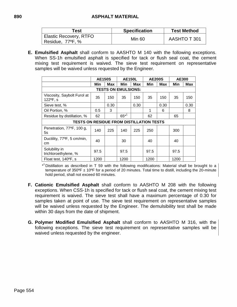
890 ASPHALT MATERIAL
Page 554
Test Specification Test Method Elastic Recovery, RTFO Residue, 77ºF, % Min 60 AASHTO T 301
E. Emulsified Asphalt shall conform to AASHTO M 140 with the following exceptions.
When SS-1h emulsified asphalt is specified for tack or flush seal coat, the cement mixing test requirement is waived. The sieve test requirement on representative samples will be waived unless requested by the Engineer.
AE150S AE150L AE200S AE300 Min Max Min Max Min Max Min Max
TESTS ON EMULSIONS: Viscosity, Saybolt Furol at 122ºF, s 35 150 35 150 35 150 35 150
Sieve test, % 0.30 0.30 0.30 0.30 Oil Portion, % 0.5 3 1 6 8 Residue by distillation, % 62 65*1 62 65
TESTS ON RESIDUE FROM DISTILLATION TESTS Penetration, 77ºF, 100 g, 5s 140 225 140 225 250 300
Ductility, 77ºF, 5 cm/min, cm 40 30 40 40
Solubility in trichloroethylene, % 97.5 97.5 97.5 97.5
Float test, 140ºF, s 1200 1200 1200 1200
*1 Distillation as described in T 59 with the following modifications: Material shall be brought to a temperature of 350ºF ± 10ºF for a period of 20 minutes. Total time to distill, including the 20-minute hold period, shall not exceed 60 minutes.
F. Cationic Emulsified Asphalt shall conform to AASHTO M 208 with the following
exceptions. When CSS-1h is specified for tack or flush seal coat, the cement mixing test requirement is waived. The sieve test shall have a maximum percentage of 0.30 for samples taken at point of use. The sieve test requirement on representative samples will be waived unless requested by the Engineer. The demulsibility test shall be made within 30 days from the date of shipment.
G. Polymer Modified Emulsified Asphalt shall conform to AASHTO M 316, with the
following exceptions. The sieve test requirement on representative samples will be waived unless requested by the engineer.
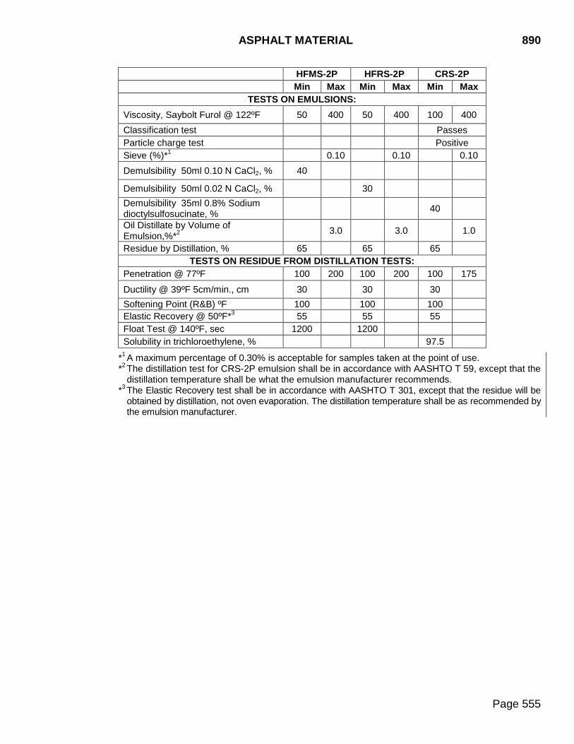
ASPHALT MATERIAL 890
Page 555
HFMS-2P HFRS-2P CRS-2P Min Max Min Max Min Max
TESTS ON EMULSIONS: Viscosity, Saybolt Furol @ 122ºF 50 400 50 400 100 400 Classification test Passes Particle charge test Positive Sieve (%)*1 0.10 0.10 0.10 Demulsibility 50ml 0.10 N CaCl2, % 40
Demulsibility 50ml 0.02 N CaCl2, % 30 Demulsibility 35ml 0.8% Sodium dioctylsulfosucinate, % 40
Oil Distillate by Volume of Emulsion,%*2 3.0 3.0 1.0
Residue by Distillation, % 65 65 65 TESTS ON RESIDUE FROM DISTILLATION TESTS:
Penetration @ 77ºF 100 200 100 200 100 175
Ductility @ 39ºF 5cm/min., cm 30 30 30 Softening Point (R&B) ºF 100 100 100 Elastic Recovery @ 50ºF*3 55 55 55 Float Test @ 140ºF, sec 1200 1200 Solubility in trichloroethylene, % 97.5
*1 A maximum percentage of 0.30% is acceptable for samples taken at the point of use. *2 The distillation test for CRS-2P emulsion shall be in accordance with AASHTO T 59, except that the
distillation temperature shall be what the emulsion manufacturer recommends. *3 The Elastic Recovery test shall be in accordance with AASHTO T 301, except that the residue will be
obtained by distillation, not oven evaporation. The distillation temperature shall be as recommended by the emulsion manufacturer.
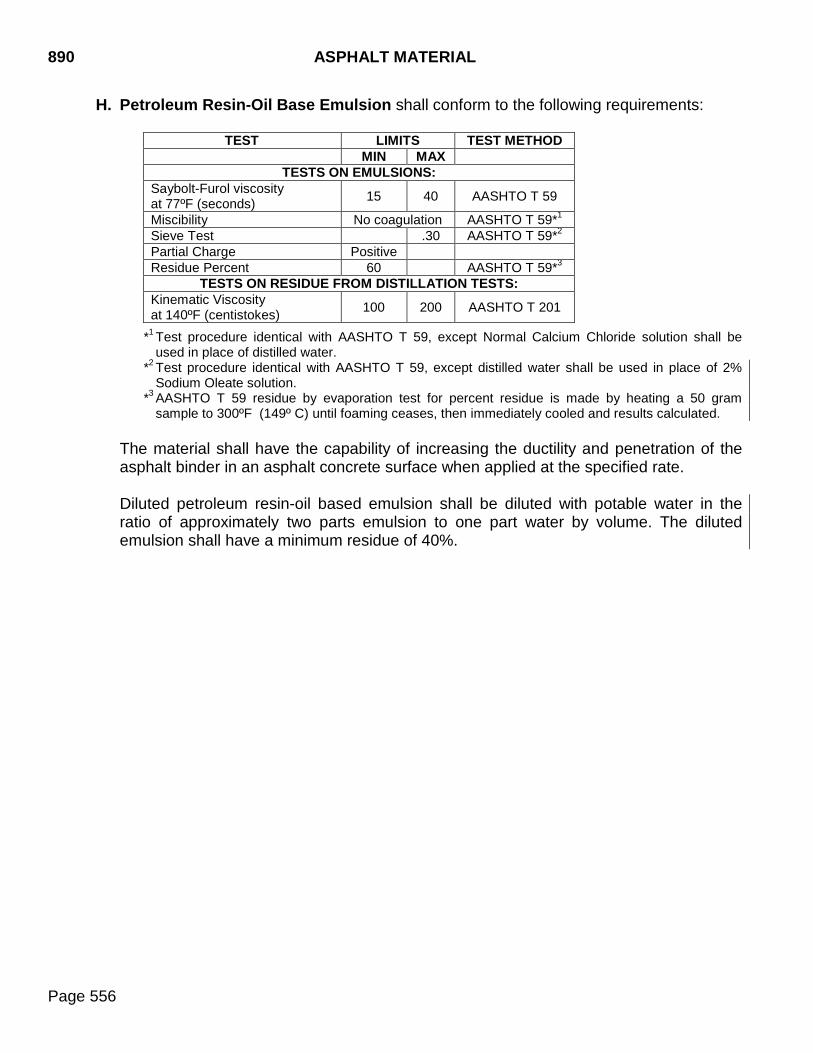
890 ASPHALT MATERIAL
Page 556
H. Petroleum Resin-Oil Base Emulsion shall conform to the following requirements:
TEST LIMITS TEST METHOD MIN MAX
TESTS ON EMULSIONS: Saybolt-Furol viscosity at 77ºF (seconds) 15 40 AASHTO T 59
Miscibility No coagulation AASHTO T 59*1 Sieve Test .30 AASHTO T 59*2 Partial Charge Positive Residue Percent 60 AASHTO T 59*3
TESTS ON RESIDUE FROM DISTILLATION TESTS: Kinematic Viscosity at 140ºF (centistokes) 100 200 AASHTO T 201
*1 Test procedure identical with AASHTO T 59, except Normal Calcium Chloride solution shall be used in place of distilled water.
*2 Test procedure identical with AASHTO T 59, except distilled water shall be used in place of 2% Sodium Oleate solution.
*3 AASHTO T 59 residue by evaporation test for percent residue is made by heating a 50 gram sample to 300ºF (149º C) until foaming ceases, then immediately cooled and results calculated.
The material shall have the capability of increasing the ductility and penetration of the asphalt binder in an asphalt concrete surface when applied at the specified rate. Diluted petroleum resin-oil based emulsion shall be diluted with potable water in the ratio of approximately two parts emulsion to one part water by volume. The diluted emulsion shall have a minimum residue of 40%.

DUST CONTROL CHLORIDES 891
Page 557
891 DUST CONTROL CHLORIDES Dust control chlorides shall conform to the following specification requirements: A bill of lading shall accompany each delivery of calcium chloride or magnesium chloride. The bill of lading shall contain the following information:
1. The gallons of solution. 2. The weight of the solution. 3. The percent concentration by weight of anhydrous calcium chloride or anhydrous
magnesium chloride. 4. The specific gravity and temperature of the solution at the time of loading.
Each delivery of material to be used will be sampled by the Department, and submitted for a chemical analysis to the Department’s Materials & Surfacing Central Laboratory.
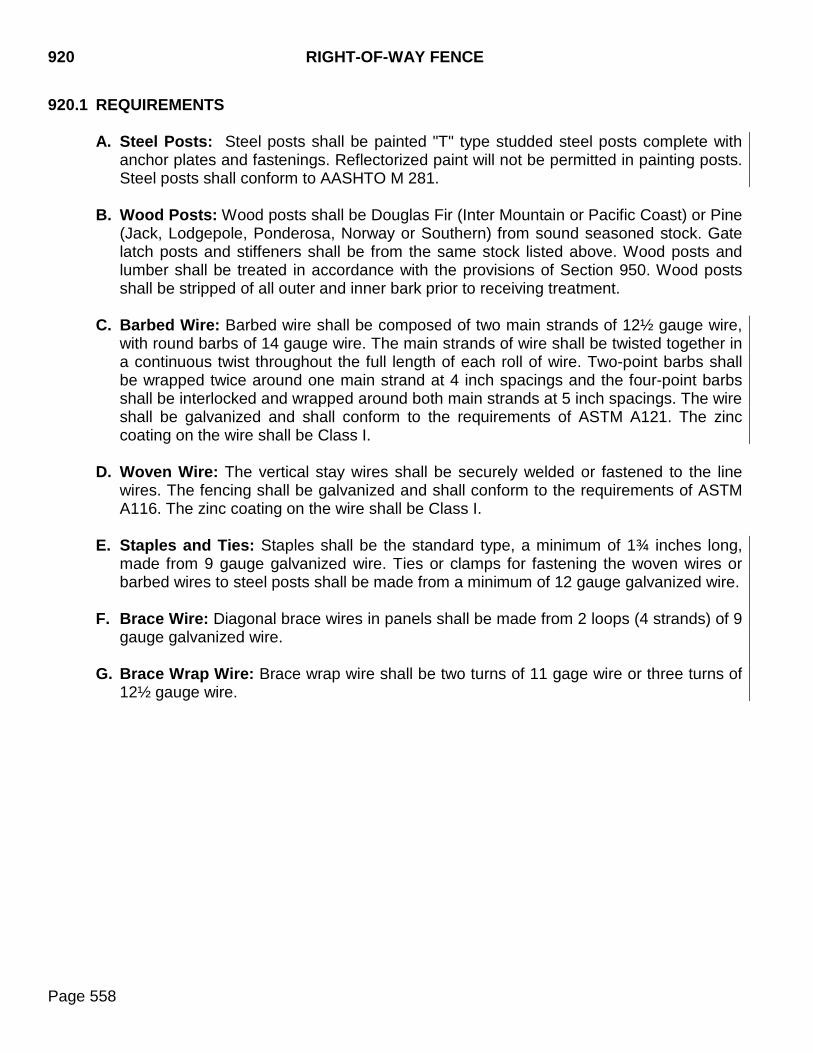
920 RIGHT-OF-WAY FENCE
Page 558
920.1 REQUIREMENTS
A. Steel Posts: Steel posts shall be painted "T" type studded steel posts complete with anchor plates and fastenings. Reflectorized paint will not be permitted in painting posts. Steel posts shall conform to AASHTO M 281.
B. Wood Posts: Wood posts shall be Douglas Fir (Inter Mountain or Pacific Coast) or Pine
(Jack, Lodgepole, Ponderosa, Norway or Southern) from sound seasoned stock. Gate latch posts and stiffeners shall be from the same stock listed above. Wood posts and lumber shall be treated in accordance with the provisions of Section 950. Wood posts shall be stripped of all outer and inner bark prior to receiving treatment.
C. Barbed Wire: Barbed wire shall be composed of two main strands of 12½ gauge wire,
with round barbs of 14 gauge wire. The main strands of wire shall be twisted together in a continuous twist throughout the full length of each roll of wire. Two-point barbs shall be wrapped twice around one main strand at 4 inch spacings and the four-point barbs shall be interlocked and wrapped around both main strands at 5 inch spacings. The wire shall be galvanized and shall conform to the requirements of ASTM A121. The zinc coating on the wire shall be Class I.
D. Woven Wire: The vertical stay wires shall be securely welded or fastened to the line
wires. The fencing shall be galvanized and shall conform to the requirements of ASTM A116. The zinc coating on the wire shall be Class I.
E. Staples and Ties: Staples shall be the standard type, a minimum of 1¾ inches long,
made from 9 gauge galvanized wire. Ties or clamps for fastening the woven wires or barbed wires to steel posts shall be made from a minimum of 12 gauge galvanized wire.
F. Brace Wire: Diagonal brace wires in panels shall be made from 2 loops (4 strands) of 9
gauge galvanized wire.
G. Brace Wrap Wire: Brace wrap wire shall be two turns of 11 gage wire or three turns of 12½ gauge wire.
CHAIN LINK FENCE 930
Page 559
930 CHAIN LINK FENCE
Chain link fence material shall conform to AASHTO M 181. Chain link fabric, posts, rails, ties, bands, bars, rods, and other fittings and hardware shall be Type I. Chain link fabric shall be 9 gauge. Posts, rail, and gate frames shall be Grade 1 or 2. Grade 2 posts, if used, shall have an exterior PVC coating conforming to Class A or an exterior coating of hot-dip zinc plus an organic topcoat and a zinc rich or hot-dip zinc interior coating. The fabric shall have a Class C coating. Tension wire shall be Class 2.
950 WOOD PRESERVATIVES AND PRESERVATIVE TREATMENTS
Page 560
950.1 REQUIREMENTS A. General
The preservative treatment shall be in compliance with the EPA, AASHTO M 133, and the AWPA Standard U1 referenced in AASHTO M 133 and described below.
Commodity Specification A – Sawn Products*1
Commodity Specification B – Post Commodity Specification D – Poles Commodity Specification E – Round Timber Piling *1 Guardrail posts and blocks shall be treated with retention specifications from commodity
specification B, use category 4B.
B. Preservative Selection
1. Sawed posts, round posts, poles, and lumber in contact with the ground shall be treated with creosote, ammoniacal copper zinc arsenate, copper naphthenate, pentachlorophenol, or chromated copper arsenate.
2. Lumber not in contact with the ground shall be treated with ammoniacal copper zinc
arsenate, copper naphthenate, pentachlorophenol, or chromated copper arsenate.
3. Round timber piling shall be treated with creosote, copper naphthenate, or pentachlorophenol.
C. Western Red Cedar
Wood preservative treatment for Western Red Cedar is not required and shall be exempt from the above requirements.
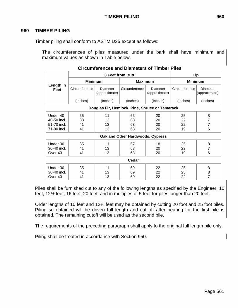
TIMBER PILING 960
Page 561
960 TIMBER PILING
Timber piling shall conform to ASTM D25 except as follows: The circumferences of piles measured under the bark shall have minimum and maximum values as shown in Table below.
Circumferences and Diameters of Timber Piles
Length in Feet
3 Feet from Butt Tip Minimum Maximum Minimum
Circumference
(Inches)
Diameter (approximate)
(Inches)
Circumference
(Inches)
Diameter (approximate)
(Inches)
Circumference
(Inches)
Diameter (approximate)
(Inches)
Douglas Fir, Hemlock, Pine, Spruce or Tamarack
Under 40 40-50 incl. 51-70 incl. 71-90 incl.
35 38 41 41
11 12 13 13
63 63 63 63
20 20 20 20
25 22 22 19
8 7 7 6
Oak and Other Hardwoods, Cypress
Under 30 30-40 incl. Over 40
35 41 41
11 13 13
57 63 63
18 20 20
25 22 19
8 7 6
Cedar
Under 30 30-40 incl. Over 40
35 41 41
11 13 13
69 69 69
22 22 22
25 25 22
8 8 7
Piles shall be furnished cut to any of the following lengths as specified by the Engineer: 10 feet, 12½ feet, 16 feet, 20 feet, and in multiples of 5 feet for piles longer than 20 feet. Order lengths of 10 feet and 12½ feet may be obtained by cutting 20 foot and 25 foot piles. Piling so obtained will be driven full length and cut off after bearing for the first pile is obtained. The remaining cutoff will be used as the second pile. The requirements of the preceding paragraph shall apply to the original full length pile only. Piling shall be treated in accordance with Section 950.
970 STEEL STRUCTURES MATERIAL
Page 562
970.1 GENERAL These specifications apply to bolted and welded construction.
970.2 STRUCTURAL STEEL
Structural steel shall be furnished according to the following specifications. Unless otherwise specified, all structural steel furnished shall conform to AASHTO M 270 (ASTM A709). When ASTM A709 structural steel with a “T” or an “F” and a temperature zone is specified, the structural steel shall be Charpy impact tested to the specified zone. Sampling and testing procedures shall be in accordance with ASTM A673 utilizing (H) frequency testing for Grade 36, 50 and 50W steels and utilizing (P) frequency testing for Grade 100 and 100W steels. For Grade 50 and 50W steels, if the yield point of the material exceeds 65 ksi, the temperature for the CVN value for acceptability shall be reduced by 15°F for each increment of 10 ksi above 65 ksi.
A. High-Strength Bolts: High-strength bolts shall conform to Section 972. B. Welded Stud Shear Connectors: Shear connector studs shall conform to the
requirements of Section 7.3, Type B of the latest edition of the ANSI/AASHTO/AWS D1.5 Bridge Welding Code and the following. Finished studs shall be of uniform quality and condition, free from injurious laps, fins, seams, cracks, twists, bends, or other injurious defects. Finish shall be as produced by cold drawing, cold rolling or machining. The manufacturer shall certify that the studs as delivered are in accordance with the material requirements of this section. Certified copies of in-plant quality control test reports shall be furnished upon request. The Engineer may select, at the Contractor's expense, studs of each type and size used under the contract, as necessary for checking the requirements of this section.
C. Tubular Steel Piles: Tubular steel piles shall conform to ASTM A252, Grade 2, with chemical requirements meeting ASTM A53, Grade B.
970.3 STEEL FORGINGS AND STEEL SHAFTING
A. Steel Forgings: Steel forgings shall conform to, AASHTO M 102 (ASTM A668), Classes C, D, F, or G.
B. Cold Finished Carbon Steel Shafting: Cold finished carbon steel shafting shall
conform to, AASHTO M 169 (ASTM A108). Grade 1016-1030, inclusive, shall be
STEEL STRUCTURES MATERIAL 970
Page 563
furnished.
970.4 GALVANIZING When specified, ferrous metal products shall be galvanized in accordance with, AASHTO M 111 (ASTM A123).
970.5 PREFORMED FABRIC PADS
Preformed fabric pads shall be composed of multiple layers of 8 ounce cotton duck impregnated and bound with high-quality natural rubber or of equivalent and equally suitable materials compressed into resilient pads of uniform thickness. The number of plies shall be such as to produce the specified thickness, after compression and vulcanizing. The finished pads shall withstand compression loads perpendicular to the plane of the laminations of not less than 10,000 pounds per square inch without reduction in thickness or extrusion.
970.6 BRONZE OR COPPER-ALLOY BEARING AND EXPANSION PLATES
The sliding surfaces of these plates shall be finished in the direction of the motion to ANSI B46.1 #125. This surface shall be bored on a geometric pattern of recesses and be lubricated with a material suitable for long-life service of the sliding face. The lubricated area shall comprise approximately 25% of the bearing face to provide coefficient of friction not to exceed 10% for loads of 600 to 1,000 psi. The edges of the plate shall be chamfered 1/8 inch.
A. Bronze Bearing and Expansion Plates: Bronze bearing and expansion plates shall
conform to, AASHTO M 107 (ASTM B22) Alloy 911.
B. Rolled Copper-Alloy Bearings and Expansion Plates: Rolled copper-alloy bearing and expansion plates shall conform to, AASHTO M 108 (ASTM B100), Alloy #510 or #511.
972 BOLTS
Page 564
972.1 REQUIREMENTS
These specifications shall apply to all high strength bolts, anchor bolts, and anchor rods. 972.2 SPECIFIC REQUIREMENTS
A. General:
All bolts, anchor bolts, anchor rods, nuts, and washers shall have the manufacturer marking on them. The supplier shall provide the symbol and address of each bolt, anchor bolt, anchor rod, nut, and washer manufacturer.
The supplier and contractor shall maintain the identification and integrity of fasteners supplied under either the “Production Lot” or “Shipping Lot” method. All certificates, test reports, and shipping containers shall be identified with the appropriate lot identification number. The Contractor shall either pre-assemble bolts, anchor bolts, anchor rods, nuts, and washers according to the certified rotational capacity tests or indicate how he plans to maintain the integrity of the lots through installation.
The supplier’s certification shall provide a lot number, which shall match the shipping package. The certification shall provide all test results and shall indicate when and where all testing was done, including the rotational capacity tests and the zinc coating thickness.
Nuts for mechanically galvanized fasteners shall be overtapped to the minimum amount required for fastener assembly.
All bolts, nuts, washers, and direct tension indicators shall be mechanically galvanized in accordance with ASTM B695 Class 55. When direct tension indicators are used adjacent to weathering steel, the direct tension indicators shall be mechanically galvanized in accordance with ASTM B695 Class 55 and epoxy coated in accordance with ASTM F959. Mechanically galvanized nuts shall be lubricated with a lubricant containing a visible dye.
The test data referred to in 11.1 of ASTM A563 and 13.2 and 13.3 of A194 shall be furnished.
B. High Strength Bolts:
Bolts shall conform to ASTM A325. Nuts shall conform to ASTM A563 DH or ASTM A194 2H. Washers shall conform to ASTM F436.
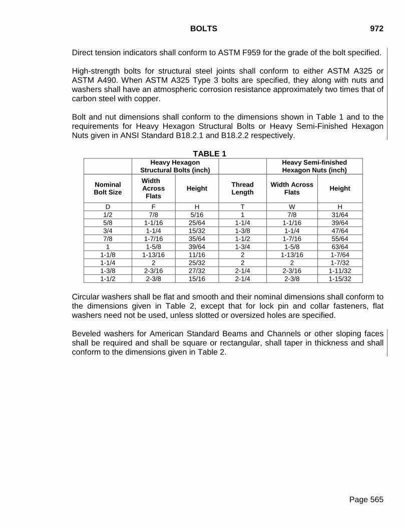
BOLTS 972
Page 565
Direct tension indicators shall conform to ASTM F959 for the grade of the bolt specified.
High-strength bolts for structural steel joints shall conform to either ASTM A325 or ASTM A490. When ASTM A325 Type 3 bolts are specified, they along with nuts and washers shall have an atmospheric corrosion resistance approximately two times that of carbon steel with copper. Bolt and nut dimensions shall conform to the dimensions shown in Table 1 and to the requirements for Heavy Hexagon Structural Bolts or Heavy Semi-Finished Hexagon Nuts given in ANSI Standard B18.2.1 and B18.2.2 respectively.
TABLE 1
Heavy Hexagon Structural Bolts (inch) Heavy Semi-finished
Hexagon Nuts (inch)
Nominal Bolt Size
Width Across Flats
Height Thread Length
Width Across Flats Height
D F H T W H 1/2 7/8 5/16 1 7/8 31/64 5/8 1-1/16 25/64 1-1/4 1-1/16 39/64 3/4 1-1/4 15/32 1-3/8 1-1/4 47/64 7/8 1-7/16 35/64 1-1/2 1-7/16 55/64 1 1-5/8 39/64 1-3/4 1-5/8 63/64
1-1/8 1-13/16 11/16 2 1-13/16 1-7/64 1-1/4 2 25/32 2 2 1-7/32 1-3/8 2-3/16 27/32 2-1/4 2-3/16 1-11/32 1-1/2 2-3/8 15/16 2-1/4 2-3/8 1-15/32
Circular washers shall be flat and smooth and their nominal dimensions shall conform to the dimensions given in Table 2, except that for lock pin and collar fasteners, flat washers need not be used, unless slotted or oversized holes are specified. Beveled washers for American Standard Beams and Channels or other sloping faces shall be required and shall be square or rectangular, shall taper in thickness and shall conform to the dimensions given in Table 2.
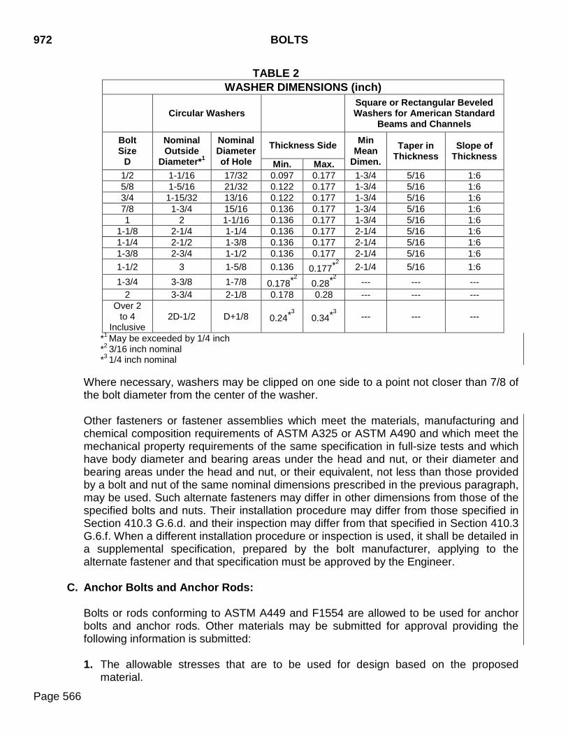
972 BOLTS
Page 566
TABLE 2 WASHER DIMENSIONS (inch)
Circular Washers Square or Rectangular Beveled Washers for American Standard
Beams and Channels
Bolt Size
D
Nominal Outside
Diameter*1
Nominal Diameter of Hole
Thickness Side Min Mean
Dimen. Taper in
Thickness Slope of
Thickness Min. Max.
1/2 1-1/16 17/32 0.097 0.177 1-3/4 5/16 1:6 5/8 1-5/16 21/32 0.122 0.177 1-3/4 5/16 1:6 3/4 1-15/32 13/16 0.122 0.177 1-3/4 5/16 1:6 7/8 1-3/4 15/16 0.136 0.177 1-3/4 5/16 1:6 1 2 1-1/16 0.136 0.177 1-3/4 5/16 1:6
1-1/8 2-1/4 1-1/4 0.136 0.177 2-1/4 5/16 1:6 1-1/4 2-1/2 1-3/8 0.136 0.177 2-1/4 5/16 1:6 1-3/8 2-3/4 1-1/2 0.136 0.177 2-1/4 5/16 1:6 1-1/2 3 1-5/8 0.136 0.177*2
2-1/4 5/16 1:6 1-3/4 3-3/8 1-7/8 0.178*2
0.28*2 --- --- --- 2 3-3/4 2-1/8 0.178 0.28 --- --- ---
Over 2 to 4
Inclusive 2D-1/2 D+1/8 0.24*3
0.34*3 --- --- ---
*1 May be exceeded by 1/4 inch *2 3/16 inch nominal *3 1/4 inch nominal
Where necessary, washers may be clipped on one side to a point not closer than 7/8 of the bolt diameter from the center of the washer. Other fasteners or fastener assemblies which meet the materials, manufacturing and chemical composition requirements of ASTM A325 or ASTM A490 and which meet the mechanical property requirements of the same specification in full-size tests and which have body diameter and bearing areas under the head and nut, or their diameter and bearing areas under the head and nut, or their equivalent, not less than those provided by a bolt and nut of the same nominal dimensions prescribed in the previous paragraph, may be used. Such alternate fasteners may differ in other dimensions from those of the specified bolts and nuts. Their installation procedure may differ from those specified in Section 410.3 G.6.d. and their inspection may differ from that specified in Section 410.3 G.6.f. When a different installation procedure or inspection is used, it shall be detailed in a supplemental specification, prepared by the bolt manufacturer, applying to the alternate fastener and that specification must be approved by the Engineer.
C. Anchor Bolts and Anchor Rods:
Bolts or rods conforming to ASTM A449 and F1554 are allowed to be used for anchor bolts and anchor rods. Other materials may be submitted for approval providing the following information is submitted:
1. The allowable stresses that are to be used for design based on the proposed
material.
BOLTS 972
Page 567
2. Minimum average Charpy V-Notch impact values for 15 ft-lb at -20°F in accordance with ASTM A370.
3. Ultimate wedge tensile strength in accordance with ASTM A370. 4. Yield strength reports in accordance with ASTM A370.
Anchor bolts and anchor rods shall be either threaded full length or equipped with a satisfactory mechanical end anchorage. Details for any mechanical end anchorage shall be included in the shop plans submittal for prior approval. Swaged anchor bolts and anchor rods and anchor bolts and anchor rods with hooked end anchorage are not allowed. The anchor bolt and anchor rod threads shall be three inches plus the projection. At least three 3 inches of threads shall be below the top of the concrete. Rolled UNC threads are required for all anchor bolts and anchor rods.
Nuts shall conform to ASTM A194, 2H or ASTM A563, DH. All nuts are to be heavy hex.
Jam nuts shall conform to ASTM A563 Grade A.
Washers shall conform to ASTM F436.
Direct tension indicators shall conform to ASTM F2437 for the grade of the bolt specified. Direct tension indicators shall be mechanically galvanized in accordance with ASTM B695, Class 55. Anchor bolts, anchor rods, nuts, and washers shall be hot dipped galvanized or mechanically galvanized. Anchor bolts and anchor rods shall be galvanized the full length.
D. Bolt, Anchor Bolt, and Anchor Rod Testing: Bolt, anchor bolt, and anchor rod testing shall conform to the following:
When bolts, anchor bolts, or anchor rods conforming to ASTM A325, A449, A307, F1554 are designated for use in the plans or shop plans, a Certified Mill Test Report for each type designated shall be submitted for approval to the Certification Engineer a minimum of 14 days prior to incorporating these bolts into the work. Certified Mill Test Reports for nuts, washers, direct tension indicators, and other required hardware shall be included.
The Certified Mill Test Reports for the bolts, anchor bolts, and anchor rods shall include test results, tested in accordance with the applicable ASTM Specifications, for the following:
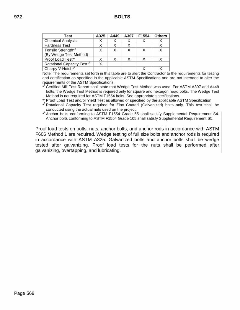
972 BOLTS
Page 568
Test A325 A449 A307 F1554 Others
Chemical Analysis X X X X X Hardness Test X X X X Tensile Strength*1 (By Wedge Test Method)
X X X X X
Proof Load Test*2 X X X X X Rotational Capacity Test*3 X Charpy V-Notch*4 X X
Note: The requirements set forth in this table are to alert the Contractor to the requirements for testing and certification as specified in the applicable ASTM Specifications and are not intended to alter the requirements of the ASTM Specifications. *1 Certified Mill Test Report shall state that Wedge Test Method was used. For ASTM A307 and A449
bolts, the Wedge Test Method is required only for square and hexagon head bolts. The Wedge Test Method is not required for ASTM F1554 bolts. See appropriate specifications.
*2 Proof Load Test and/or Yield Test as allowed or specified by the applicable ASTM Specification. *3 Rotational Capacity Test required for Zinc Coated (Galvanized) bolts only. This test shall be
conducted using the actual nuts used on the project. *4 Anchor bolts conforming to ASTM F1554 Grade 55 shall satisfy Supplemental Requirement S4.
Anchor bolts conforming to ASTM F1554 Grade 105 shall satisfy Supplemental Requirement S5.
Proof load tests on bolts, nuts, anchor bolts, and anchor rods in accordance with ASTM F606 Method 1 are required. Wedge testing of full size bolts and anchor rods is required in accordance with ASTM A325. Galvanized bolts and anchor bolts shall be wedge tested after galvanizing. Proof load tests for the nuts shall be performed after galvanizing, overtapping, and lubricating.
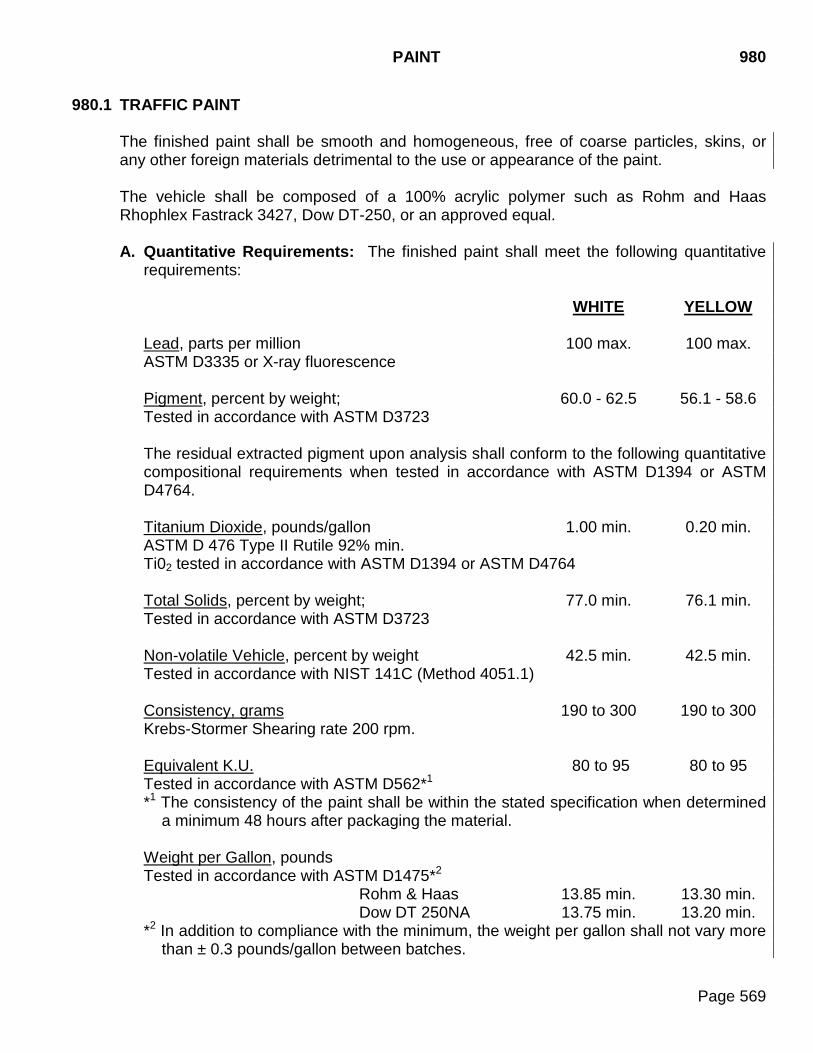
PAINT 980
Page 569
980.1 TRAFFIC PAINT
The finished paint shall be smooth and homogeneous, free of coarse particles, skins, or any other foreign materials detrimental to the use or appearance of the paint. The vehicle shall be composed of a 100% acrylic polymer such as Rohm and Haas Rhophlex Fastrack 3427, Dow DT-250, or an approved equal. A. Quantitative Requirements: The finished paint shall meet the following quantitative
requirements:
WHITE YELLOW Lead, parts per million 100 max. 100 max. ASTM D3335 or X-ray fluorescence Pigment, percent by weight; 60.0 - 62.5 56.1 - 58.6 Tested in accordance with ASTM D3723
The residual extracted pigment upon analysis shall conform to the following quantitative compositional requirements when tested in accordance with ASTM D1394 or ASTM D4764. Titanium Dioxide, pounds/gallon 1.00 min. 0.20 min. ASTM D 476 Type II Rutile 92% min. Ti02 tested in accordance with ASTM D1394 or ASTM D4764 Total Solids, percent by weight; 77.0 min. 76.1 min. Tested in accordance with ASTM D3723 Non-volatile Vehicle, percent by weight 42.5 min. 42.5 min. Tested in accordance with NIST 141C (Method 4051.1) Consistency, grams 190 to 300 190 to 300 Krebs-Stormer Shearing rate 200 rpm. Equivalent K.U. 80 to 95 80 to 95 Tested in accordance with ASTM D562*1 *1 The consistency of the paint shall be within the stated specification when determined
a minimum 48 hours after packaging the material. Weight per Gallon, pounds Tested in accordance with ASTM D1475*2 Rohm & Haas 13.85 min. 13.30 min. Dow DT 250NA 13.75 min. 13.20 min. *2 In addition to compliance with the minimum, the weight per gallon shall not vary more
than ± 0.3 pounds/gallon between batches.
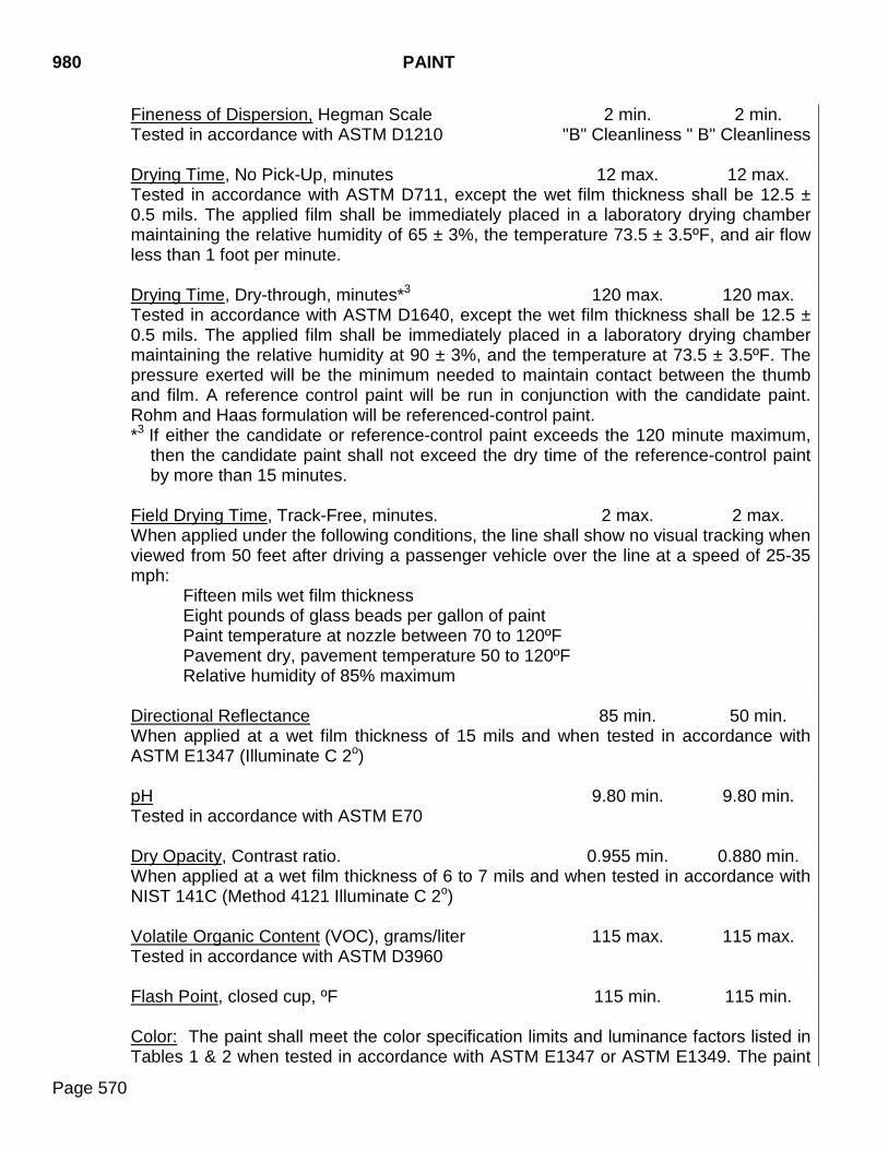
980 PAINT
Page 570
Fineness of Dispersion, Hegman Scale 2 min. 2 min. Tested in accordance with ASTM D1210 "B" Cleanliness " B" Cleanliness Drying Time, No Pick-Up, minutes 12 max. 12 max. Tested in accordance with ASTM D711, except the wet film thickness shall be 12.5 ± 0.5 mils. The applied film shall be immediately placed in a laboratory drying chamber maintaining the relative humidity of 65 ± 3%, the temperature 73.5 ± 3.5ºF, and air flow less than 1 foot per minute. Drying Time, Dry-through, minutes*3 120 max. 120 max. Tested in accordance with ASTM D1640, except the wet film thickness shall be 12.5 ± 0.5 mils. The applied film shall be immediately placed in a laboratory drying chamber maintaining the relative humidity at 90 ± 3%, and the temperature at 73.5 ± 3.5ºF. The pressure exerted will be the minimum needed to maintain contact between the thumb and film. A reference control paint will be run in conjunction with the candidate paint. Rohm and Haas formulation will be referenced-control paint. *3 If either the candidate or reference-control paint exceeds the 120 minute maximum,
then the candidate paint shall not exceed the dry time of the reference-control paint by more than 15 minutes.
Field Drying Time, Track-Free, minutes. 2 max. 2 max. When applied under the following conditions, the line shall show no visual tracking when viewed from 50 feet after driving a passenger vehicle over the line at a speed of 25-35 mph:
Fifteen mils wet film thickness Eight pounds of glass beads per gallon of paint Paint temperature at nozzle between 70 to 120ºF Pavement dry, pavement temperature 50 to 120ºF Relative humidity of 85% maximum
Directional Reflectance 85 min. 50 min. When applied at a wet film thickness of 15 mils and when tested in accordance with ASTM E1347 (Illuminate C 2o) pH 9.80 min. 9.80 min. Tested in accordance with ASTM E70 Dry Opacity, Contrast ratio. 0.955 min. 0.880 min. When applied at a wet film thickness of 6 to 7 mils and when tested in accordance with NIST 141C (Method 4121 Illuminate C 2o) Volatile Organic Content (VOC), grams/liter 115 max. 115 max. Tested in accordance with ASTM D3960 Flash Point, closed cup, ºF 115 min. 115 min. Color: The paint shall meet the color specification limits and luminance factors listed in Tables 1 & 2 when tested in accordance with ASTM E1347 or ASTM E1349. The paint
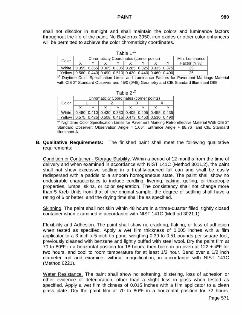
PAINT 980
Page 571
shall not discolor in sunlight and shall maintain the colors and luminance factors throughout the life of the paint. No Bayferrox 3950, iron oxides or other color enhancers will be permitted to achieve the color chromaticity coordinates.
Table 1*1 Color Chromaticity Coordinates (corner points) Min. Luminance
Factor (Y %) X Y X Y X Y X Y White 0.355 0.355 0.305 0.305 0.285 0.325 0.335 0.375 35 Yellow 0.560 0.440 0.490 0.510 0.420 0.440 0.460 0.400 25
*1 Daytime Color Specification Limits and Luminance Factors for Pavement Markings Material with CIE 2° Standard Observer and 45/0 (0/45) Geometry and CIE Standard Illuminant D65
Table 2*2
Color Chromaticity Coordinates (corner points)
1 2 3 4 X Y X Y X Y X Y
White 0.480 0.410 0.430 0.380 0.405 0.405 0.455 0.435 Yellow 0.575 0.425 0.508 0.415 0.473 0.453 0.510 0.490
*2 Nighttime Color Specification Limits for Pavement Marking Retroreflective Material With CIE 2° Standard Observer, Observation Angle = 1.05°, Entrance Angle + 88.76° and CIE Standard Illuminant A.
B. Qualitative Requirements: The finished paint shall meet the following qualitative requirements: Condition in Container - Storage Stability. Within a period of 12 months from the time of delivery and when examined in accordance with NIST 141C (Method 3011.2), the paint shall not show excessive settling in a freshly-opened full can and shall be easily redispersed with a paddle to a smooth homogeneous state. The paint shall show no undesirable characteristics to include curdling, livering, caking, gelling, or thixotropic properties, lumps, skins, or color separation. The consistency shall not change more than 5 Kreb Units from that of the original sample, the degree of settling shall have a rating of 6 or better, and the drying time shall be as specified. Skinning. The paint shall not skin within 48 hours in a three-quarter filled, tightly closed container when examined in accordance with NIST 141C (Method 3021.1). Flexibility and Adhesion. The paint shall show no cracking, flaking, or loss of adhesion when tested as specified. Apply a wet film thickness of 0.005 inches with a film applicator to a 3 inch x 5 inch tin panel weighing 0.39 to 0.51 pounds per square foot, previously cleaned with benzene and lightly buffed with steel wool. Dry the paint film at 70 to 80ºF in a horizontal position for 18 hours, then bake in an oven at 122 ± 4ºF for two hours, and cool to room temperature for at least 1/2 hour. Bend over a 1/2 inch diameter rod and examine, without magnification, in accordance with NIST 141C (Method 6221). Water Resistance. The paint shall show no softening, blistering, loss of adhesion or other evidence of deterioration, other than a slight loss in gloss when tested as specified. Apply a wet film thickness of 0.015 inches with a film applicator to a clean glass plate. Dry the paint film at 70 to 80ºF in a horizontal position for 72 hours.
980 PAINT
Page 572
Immerse one-half of the painted plate in distilled water in a vertical position at room temperature (70 to 80ºF) for 18 hours in accordance with NIST 141C (Method 6011). Remove the painted plate from the immersion liquid, allow to air dry for two hours, and then examine. Dilution Stability. The paint shall be capable of dilution with water with no separation, curdling or precipitation observed when examined in accordance with NIST 141C (Method 4203.1), such that the wet paint can be readily cleanable with only water. Spraying Properties. The paint as received shall have satisfactory spraying and hiding properties when applied by either airless or air-assisted type traffic stripers to glass or metal plates at a wet film thickness of 0.015 inches. Bleeding. The paint shall have a minimum bleeding ratio of 0.97 when tested in accordance with Federal Specification TT-P-1952 B. The asphalt saturated felt shall conform to ASTM D 226 (Type I). Freeze-Thaw Stability. The paint shall show no coagulation or change in consistency greater than 5 Kreb Units when tested in accordance with Federal Specification TT-P-1952 B. Heat Stability. The paint shall show no coagulation, discoloration, or change in consistency greater than 5 Kreb Units when tested in accordance with Federal Specification TT-P-1952 B. The degree of settling shall have a rating of 6 or better when evaluated in accordance with ASTM D869.
Abrasion Resistance. No less than 190 Liters of sand shall be required for removal of the paint film when tested in accordance with Federal Specification TT-P-1952 B. The manufacturer shall submit a "Certificate of Compliance" for each batch of paint produced for use under this specification. The certification shall contain the manufacturer’s code number and batch number along with the test results of each batch for weight per gallon, viscosity, drying time, percent pigment, percent vehicle, and fineness of grind.
GLASS BEADS 981
Page 573
981.1 GENERAL REQUIREMENTS
Glass beads for use with pavement marking paint shall be moisture resistant and shall meet the requirements of AASHTO M 247, Type II. The glass beads shall be without floatation properties. The glass beads shall have dual surface treatment consisting of a moisture resistant silicone treatment, and silane adherence surface treatment. The glass beads shall have a minimum of 80% true spheres. Roundness shall be tested in accordance with SD 510.
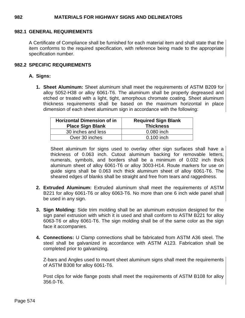
982 MATERIALS FOR HIGHWAY SIGNS AND DELINEATORS
Page 574
982.1 GENERAL REQUIREMENTS A Certificate of Compliance shall be furnished for each material item and shall state that the item conforms to the required specification, with reference being made to the appropriate specification number.
982.2 SPECIFIC REQUIREMENTS
A. Signs:
1. Sheet Aluminum: Sheet aluminum shall meet the requirements of ASTM B209 for alloy 5052-H38 or alloy 6061-T6. The aluminum shall be properly degreased and etched or treated with a light, tight, amorphous chromate coating. Sheet aluminum thickness requirements shall be based on the maximum horizontal in place dimension of each sheet aluminum sign in accordance with the following:
Horizontal Dimension of in Place Sign Blank
Required Sign Blank Thickness
30 inches and less 0.080 inch Over 30 inches 0.100 inch
Sheet aluminum for signs used to overlay other sign surfaces shall have a thickness of 0.063 inch. Cutout aluminum backing for removable letters, numerals, symbols, and borders shall be a minimum of 0.032 inch thick aluminum sheet of alloy 6061-T6 or alloy 3003-H14. Route markers for use on guide signs shall be 0.063 inch thick aluminum sheet of alloy 6061-T6. The sheared edges of blanks shall be straight and free from tears and raggedness.
2. Extruded Aluminum: Extruded aluminum shall meet the requirements of ASTM
B221 for alloy 6061-T6 or alloy 6063-T6. No more than one 6 inch wide panel shall be used in any sign.
3. Sign Molding: Side trim molding shall be an aluminum extrusion designed for the
sign panel extrusion with which it is used and shall conform to ASTM B221 for alloy 6063-T6 or alloy 6061-T6. The sign molding shall be of the same color as the sign face it accompanies.
4. Connections: U Clamp connections shall be fabricated from ASTM A36 steel. The
steel shall be galvanized in accordance with ASTM A123. Fabrication shall be completed prior to galvanizing.
Z-bars and Angles used to mount sheet aluminum signs shall meet the requirements of ASTM B308 for alloy 6061-T6. Post clips for wide flange posts shall meet the requirements of ASTM B108 for alloy 356.0-T6.
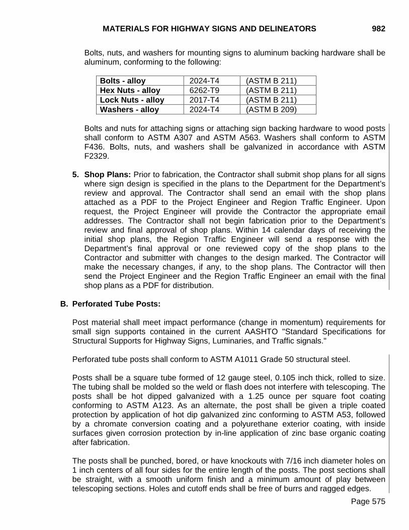
MATERIALS FOR HIGHWAY SIGNS AND DELINEATORS 982
Page 575
Bolts, nuts, and washers for mounting signs to aluminum backing hardware shall be aluminum, conforming to the following:
Bolts - alloy 2024-T4 (ASTM B 211) Hex Nuts - alloy 6262-T9 (ASTM B 211) Lock Nuts - alloy 2017-T4 (ASTM B 211) Washers - alloy 2024-T4 (ASTM B 209)
Bolts and nuts for attaching signs or attaching sign backing hardware to wood posts shall conform to ASTM A307 and ASTM A563. Washers shall conform to ASTM F436. Bolts, nuts, and washers shall be galvanized in accordance with ASTM F2329.
5. Shop Plans: Prior to fabrication, the Contractor shall submit shop plans for all signs where sign design is specified in the plans to the Department for the Department’s review and approval. The Contractor shall send an email with the shop plans attached as a PDF to the Project Engineer and Region Traffic Engineer. Upon request, the Project Engineer will provide the Contractor the appropriate email addresses. The Contractor shall not begin fabrication prior to the Department’s review and final approval of shop plans. Within 14 calendar days of receiving the initial shop plans, the Region Traffic Engineer will send a response with the Department’s final approval or one reviewed copy of the shop plans to the Contractor and submitter with changes to the design marked. The Contractor will make the necessary changes, if any, to the shop plans. The Contractor will then send the Project Engineer and the Region Traffic Engineer an email with the final shop plans as a PDF for distribution.
B. Perforated Tube Posts: Post material shall meet impact performance (change in momentum) requirements for small sign supports contained in the current AASHTO "Standard Specifications for Structural Supports for Highway Signs, Luminaries, and Traffic signals." Perforated tube posts shall conform to ASTM A1011 Grade 50 structural steel. Posts shall be a square tube formed of 12 gauge steel, 0.105 inch thick, rolled to size. The tubing shall be molded so the weld or flash does not interfere with telescoping. The posts shall be hot dipped galvanized with a 1.25 ounce per square foot coating conforming to ASTM A123. As an alternate, the post shall be given a triple coated protection by application of hot dip galvanized zinc conforming to ASTM A53, followed by a chromate conversion coating and a polyurethane exterior coating, with inside surfaces given corrosion protection by in-line application of zinc base organic coating after fabrication. The posts shall be punched, bored, or have knockouts with 7/16 inch diameter holes on 1 inch centers of all four sides for the entire length of the posts. The post sections shall be straight, with a smooth uniform finish and a minimum amount of play between telescoping sections. Holes and cutoff ends shall be free of burrs and ragged edges.
982 MATERIALS FOR HIGHWAY SIGNS AND DELINEATORS
Page 576
Bolts, nuts, and washers shall conform to ASTM A307, ASTM A563, and ASTM F436, respectively, and shall be galvanized in accordance with ASTM B695.
C. Steel Posts:
1. Structural steel posts and stiffeners shall conform to ASTM A36. Pipe posts shall conform to ASTM A53 Type E or S Grade B, ASTM A501, or ASTM A500 Grade B.
2. Steel posts (structural and pipe) and stiffeners shall be galvanized in accordance
with ASTM A123. Welding, punching, and boring of the steel posts shall be done before galvanizing.
3. Cantilever structural supports shall be fabricated steel in accordance with the
following:
a. Shapes, plates, bars, sheets, and strips equal to or over 0.23 inches thick shall conform to ASTM A709, Grade 36 or ASTM A992. Sheets and strips under 0.23 inches thick shall conform to ASTM A1011 Grade 36.
b. Pole and tubular members shall conform to ASTM A709 Grade 36 and Grade 50,
A53 Grade B, A242, A1011 Grade 36, or A595 Grade A or B. A595 material shall be limited to 3/8 inch maximum thickness. Structural support material with a thickness of 1/2 inch to 2 inches shall satisfy Charpy V-Notch toughness test requirements of 15 foot-pounds at 40°F. For material over 2 inches, contact the Office of Bridge Design for Charpy impact requirements.
4. High-strength bolts for structural steel joints, including nuts and washers, shall
conform to ASTM A325 in accordance with Section 972.
D. Wood Posts: Wood posts shall be Western Red Cedar. They shall be construction grade in compliance with the Standard Grading Rules of the Western Wood Products Association. Posts shall be surfaced four sides.
E. Sign Bridges and Overhead Cantilever Sign Supports: Sign bridges and overhead
cantilever sign supports shall be constructed in accordance with the details in the plans and at the locations shown.
1. Design Specifications: The current edition of the AASHTO Standard Specifications
for Structural Supports for Highway Signs, Luminaires, and Traffic Signals, including all subsequent interims. a. Wind load shall be calculated using the 50 year mean recurrence interval basic
wind speed. b. The cantilever supports, including anchor bolts, shall be designed for fatigue in
accordance with Fatigue Importance Category I. This is to include truck-induced
MATERIALS FOR HIGHWAY SIGNS AND DELINEATORS 982
Page 577
gust loads, natural wind gust loads, and unless installed with approved vibration mitigation devices, shall also include galloping loads.
Details for any proposed vibration mitigation devices must be submitted with the shop plans for approval by the Department prior to fabrication. Supporting documentation (historical and research data) verifying the damping characteristics of the specific mitigation device for the intended structural support application must accompany the submittal.
2. General:
a. Cantilever arms shall be truss type members. Mono-tube or single member arms
are not allowed.
b. No splices of any kind will be permitted in the vertical pole members.
c. Truss type sign supports shall have a minimum of 8 anchor bolts.
d. Anchor bolts and rods shall be provided with leveling nuts, top nuts, washers, and jam nuts.
e. All members and components shall be galvanized after fabrication in accordance
with ASTM A123, A153, or F2329 as applicable.
3. Shop Plans: Prior to fabrication, the Contractor shall submit shop plans to the Department for the Department’s review and approval. The Contractor shall send an email with the shop plans attached as a PDF and comprehensive design calculations for the sign support structure (including anchor bolts), signed and sealed by a SD Registered Professional Engineer to the Project Engineer, the Region Traffic Engineer, and the Bridge Construction Engineer. Upon request, the Project Engineer will provide the Contractor the appropriate email addresses. The Contractor shall not begin fabrication prior to the Department’s review and final approval of shop plans. Within 28 calendar days of receiving the initial shop plans, the Bridge Construction Engineer will send the Department’s approval or one reviewed copy of the shop plans to the Contractor and submitter with changes to the design marked. The Contractor will make the necessary changes, if any, to the shop plans. The Contractor will then send the Project Engineer and the Bridge Construction Engineer an email with the final shop plans as a PDF for distribution.
4. Fabrication:
a. Welding and weld inspection shall be done in accordance with the latest edition of ANSI/AWS D1.1 Structural Welding Code.
b. Approved Welding Procedure Specifications (WPS) are required for all welding.
WPS's shall be based upon Procedure Qualification Testing (PQT) in accordance with the latest edition of ANSI/AWS D1.1 Structural Welding Code.
982 MATERIALS FOR HIGHWAY SIGNS AND DELINEATORS
Page 578
c. The steel pole-to-base-plate connection shall be a full-penetration groove-welded connection with a backing ring as described in the AASHTO Standard Specifications for Structural Supports for Highway Signs, Luminaires, and Traffic Signals.
d. If welded connections are used subsequent to galvanizing, the weld details and
the procedure for preparing the surface for welding and repainting the galvanizing with zinc-rich paint after welding shall be included with the shop plans.
e. The SDDOT Bridge Construction Engineer shall be notified as to what date
fabrication will begin. This notification shall be provided a minimum of 30 calendar days prior to fabrication. The Bridge Construction Engineer will at that time arrange for fabrication inspection. Fabrication shall not begin until authorization has been given by the Department’s Bridge Construction Engineer.
F. Fixed Base Assemblies:
1. Base Plates: Base plates shall conform to ASTM A36. The base plates shall be
galvanized in accordance with ASTM A123. Welding, punching, and boring of the base plates shall be done before galvanizing.
2. Anchor Bolts and Rods: Anchor bolts, rods, and nuts shall conform to the
requirements of ASTM F1554 Grade 36. Bolts, rods, nuts, and washers shall be galvanized in accordance with ASTM F2329.
G. Slip Base Assemblies:
1. Base Plates and Friction Fuse Plates: Base plates and friction fuse plates shall
conform to ASTM A36. The plates shall be galvanized in accordance with ASTM A123. Welding, punching, and boring of the plates shall be done before galvanizing.
2. Bolts, Nuts and Washers: Bolts, hex nuts, and washers used in conjunction with
base plates or friction fuse plates shall conform to ASTM A325, except 1/2 inch and 5/8 inch bolts conforming to ASTM A449 are permissible instead of ASTM A325. Bolts, hex nuts, and washers shall be covered with zinc coating (hot dip galvanized) per ASTM F2329.
3. Shims: Shims used in conjunction with base plates or friction fuse plates shall be
covered with a zinc plating (electro-deposited zinc) as per ASTM B633.
H. Reflective Sheeting:
1. Grade: The reflective sheeting shall be of high intensity (Type IV) or super/very high intensity (Type XI) conforming to AASHTO M 268 (ASTM D4956), as specified in the plans.
MATERIALS FOR HIGHWAY SIGNS AND DELINEATORS 982
Page 579
2. General Characteristics: The reflective sheeting shall be free from ragged edges, cracks, and extraneous materials. There shall be no more than four splices per 50 yard length. Splices shall be made by overlapping the sheeting a minimum of 3/16 inch.
3. Fabrication: The background for signs shall be sheet reflective material applied to
aluminum backing. The preparation of the aluminum surface and the sheeting application shall be in complete compliance with the recommendations of the manufacturer.
All legend and border utilizing the color black shall be vinyl or screen printed black, non-reflectorized material. All other legend and border shall be of the same type of sheeting as the background of the same sign.
4. Application: Reflective sheeting shall be applied to properly prepared aluminum
(degreased and etched or treated with a light, tight, amorphous chromate coating) with mechanical equipment in a manner prescribed by the sheeting manufacturer. Sign faces comprising two or more pieces or panels of reflective sheeting must be carefully matched for color during sign fabrication to provide uniform appearance and brilliance, day and night. Alternate, successive width sections of either sheeting or panels must be reversed and consecutive to insure that corresponding edges of reflective sheeting lie adjacent on the finished sign. Reflective sheeting for extruded aluminum sign panels shall be of the pressure sensitive type. Splicing of the sheeting will not be allowed except those splices permitted by the sheeting manufacturer. The sheeting shall be rolled over the edge of the extrusion 1/4 inch to prevent an open surface on the finished sign face. Reflective sheeting for sheet aluminum signs shall be of the pressure sensitive or heat activated type. Splicing of the sheeting will not be allowed except those splices permitted by the sheeting manufacturer. Splices will not be permitted on signs which are screen processed with transparent color.
5. Legend: Message and borders shall be type, reflective material, and color specified.
Either removable copy or non-removable copy will be allowed. Non-removable copy may be screen processed or direct applied.
a. Removable Copy: Letters, numerals, symbols, borders, and route markers shall
be demountable, cut-out legend consisting of reflective sheeting applied to flat sheet aluminum backing. Letters, numerals, symbols, and borders shall be fabricated using a minimum of 0.032 inch thick aluminum sheet of ASTM B209 6061-T6 or 3003-H14 alloy. The aluminum shall be properly degreased and etched or treated with a light, tight, amorphous chromate coating. Each letter, numeral, symbol, border, and route marker shall be supplied with 9/64-inch mounting holes at no greater spacing than eight inches on center and shall be secured to the sign surface with 1/8-inch aluminum blind rivets. The heads of the rivets shall be painted the color of the legend. The finished letters, numerals,
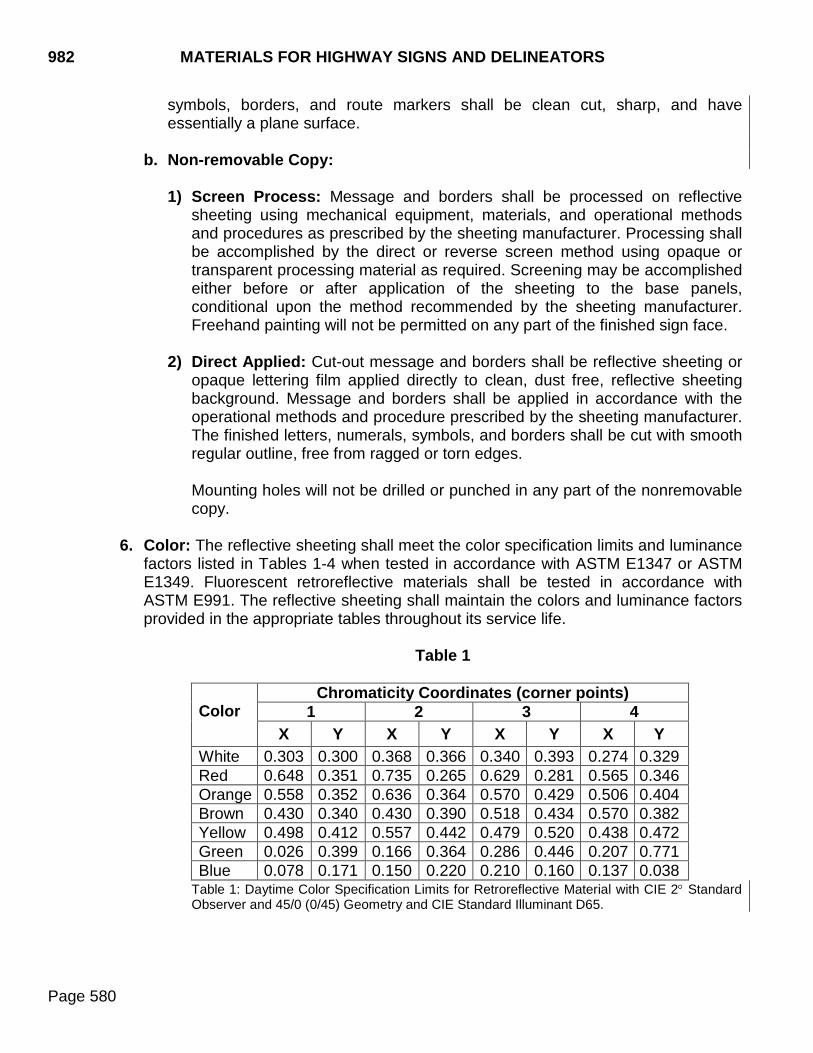
982 MATERIALS FOR HIGHWAY SIGNS AND DELINEATORS
Page 580
symbols, borders, and route markers shall be clean cut, sharp, and have essentially a plane surface.
b. Non-removable Copy:
1) Screen Process: Message and borders shall be processed on reflective
sheeting using mechanical equipment, materials, and operational methods and procedures as prescribed by the sheeting manufacturer. Processing shall be accomplished by the direct or reverse screen method using opaque or transparent processing material as required. Screening may be accomplished either before or after application of the sheeting to the base panels, conditional upon the method recommended by the sheeting manufacturer. Freehand painting will not be permitted on any part of the finished sign face.
2) Direct Applied: Cut-out message and borders shall be reflective sheeting or
opaque lettering film applied directly to clean, dust free, reflective sheeting background. Message and borders shall be applied in accordance with the operational methods and procedure prescribed by the sheeting manufacturer. The finished letters, numerals, symbols, and borders shall be cut with smooth regular outline, free from ragged or torn edges. Mounting holes will not be drilled or punched in any part of the nonremovable copy.
6. Color: The reflective sheeting shall meet the color specification limits and luminance factors listed in Tables 1-4 when tested in accordance with ASTM E1347 or ASTM E1349. Fluorescent retroreflective materials shall be tested in accordance with ASTM E991. The reflective sheeting shall maintain the colors and luminance factors provided in the appropriate tables throughout its service life.
Table 1
Color
Chromaticity Coordinates (corner points) 1 2 3 4
X Y X Y X Y X Y White 0.303 0.300 0.368 0.366 0.340 0.393 0.274 0.329 Red 0.648 0.351 0.735 0.265 0.629 0.281 0.565 0.346 Orange 0.558 0.352 0.636 0.364 0.570 0.429 0.506 0.404 Brown 0.430 0.340 0.430 0.390 0.518 0.434 0.570 0.382 Yellow 0.498 0.412 0.557 0.442 0.479 0.520 0.438 0.472 Green 0.026 0.399 0.166 0.364 0.286 0.446 0.207 0.771 Blue 0.078 0.171 0.150 0.220 0.210 0.160 0.137 0.038
Table 1: Daytime Color Specification Limits for Retroreflective Material with CIE 2° Standard Observer and 45/0 (0/45) Geometry and CIE Standard Illuminant D65.
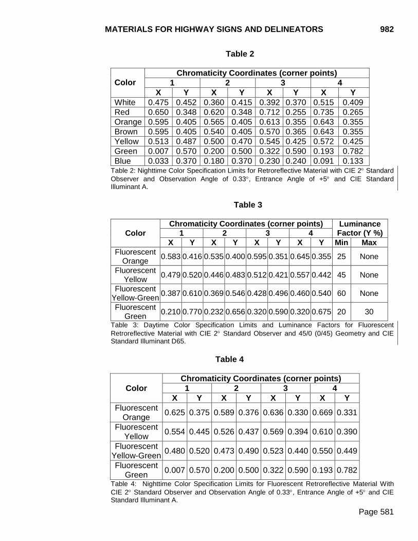
MATERIALS FOR HIGHWAY SIGNS AND DELINEATORS 982
Page 581
Table 2
Color
Chromaticity Coordinates (corner points) 1 2 3 4
X Y X Y X Y X Y White 0.475 0.452 0.360 0.415 0.392 0.370 0.515 0.409 Red 0.650 0.348 0.620 0.348 0.712 0.255 0.735 0.265 Orange 0.595 0.405 0.565 0.405 0.613 0.355 0.643 0.355 Brown 0.595 0.405 0.540 0.405 0.570 0.365 0.643 0.355 Yellow 0.513 0.487 0.500 0.470 0.545 0.425 0.572 0.425 Green 0.007 0.570 0.200 0.500 0.322 0.590 0.193 0.782 Blue 0.033 0.370 0.180 0.370 0.230 0.240 0.091 0.133
Table 2: Nighttime Color Specification Limits for Retroreflective Material with CIE 2° Standard Observer and Observation Angle of 0.33°, Entrance Angle of +5° and CIE Standard Illuminant A.
Table 3
Color Chromaticity Coordinates (corner points) Luminance
Factor (Y %) 1 2 3 4 X Y X Y X Y X Y Min Max
Fluorescent Orange 0.583 0.416 0.535 0.400 0.595 0.351 0.645 0.355 25 None
Fluorescent Yellow 0.479 0.520 0.446 0.483 0.512 0.421 0.557 0.442 45 None
Fluorescent Yellow-Green 0.387 0.610 0.369 0.546 0.428 0.496 0.460 0.540 60 None
Fluorescent Green 0.210 0.770 0.232 0.656 0.320 0.590 0.320 0.675 20 30
Table 3: Daytime Color Specification Limits and Luminance Factors for Fluorescent Retroreflective Material with CIE 2° Standard Observer and 45/0 (0/45) Geometry and CIE Standard Illuminant D65.
Table 4
Color Chromaticity Coordinates (corner points) 1 2 3 4
X Y X Y X Y X Y Fluorescent
Orange 0.625 0.375 0.589 0.376 0.636 0.330 0.669 0.331
Fluorescent Yellow 0.554 0.445 0.526 0.437 0.569 0.394 0.610 0.390
Fluorescent Yellow-Green 0.480 0.520 0.473 0.490 0.523 0.440 0.550 0.449
Fluorescent Green 0.007 0.570 0.200 0.500 0.322 0.590 0.193 0.782
Table 4: Nighttime Color Specification Limits for Fluorescent Retroreflective Material With CIE 2° Standard Observer and Observation Angle of 0.33°, Entrance Angle of +5° and CIE Standard Illuminant A.
982 MATERIALS FOR HIGHWAY SIGNS AND DELINEATORS
Page 582
I. Concrete Footings: Concrete footings shall conform to Section 462. J. Object Markers:
1. Description: Object markers shall be adhesive coated reflective sheeting
permanently bonded to sheet aluminum backing. Object markers shall be of the size and color specified. Type 1, 2, 3, and 4 object markers shall conform to the following requirements: a. Type 1 object markers shall consist of a yellow 18" x 18" reflector unit.
b. Type 2 object markers shall consist of a yellow 6" x 12" or size specified reflector
unit.
c. Type 3 object markers shall consist of a yellow and black 12" x 36" reflector unit. The yellow and black stripe pattern shall be 6” black and 4” yellow.
d. Type 4 object markers shall consist of a red 18” x 18” reflector unit.
2. Reflective Sheeting: The reflective sheeting shall be super/very high intensity
(Type XI) conforming to AASHTO M 268 (ASTM D4956). In addition to the requirements stated above, the reflective sheeting shall maintain the colors provided in the appropriate tables contained in Section 982.2 H.6 throughout its service life.
3. Fabrication: The aluminum shall be a 0.063 inch thick sheet conforming to the requirements of ASTM B 209 for alloy 6061-T6 or 5052-H38. The aluminum shall be properly degreased and etched or treated with a light, tight, amorphous chromate coating. The reflective sheeting shall be applied to properly treated base panels with mechanical equipment in a manner specified by the sheeting manufacturer.
4. Shape and Holes: Object markers shall be punched or sheared to size with 1½”
radius corners. Mounting holes shall be as follow:
a. Type 1 object markers shall have 2 holes 1/4 inch in diameter 20 inches center to center.
b. Type 2 object markers shall have 2 holes 1/4 inch in diameter 8 inches center to
center.
c. Type 3 object markers shall have 2 holes 1/4 inch in diameter 30 inches center to center.
MATERIALS FOR HIGHWAY SIGNS AND DELINEATORS 982
Page 583
d. Type 4 object markers shall have 2 holes 1/4 inch in diameter 20 inches center to center.
5. General Requirements: The finished object markers shall be free of burrs,
scratches, and damaged reflective sheeting and shall have essentially a plane surface.
6. Object Marker Posts: Posts shall be flanged channel section fabricated from hot
rolled carbon steel bars or carbon steel bars and shapes produced from standard rail steel. The posts shall meet the minimum physical properties of ASTM A499, Grade 60. The posts shall meet the chemical properties of ASTM A1 for rails 30 pounds per foot and heavier. The posts shall be painted with a baked on high quality dark green enamel. All punching, boring, cutting, or shearing shall be done prior to painting. Prior to any punching or boring, the weight of the post shall be a minimum of 1.12 pounds per foot with a tolerance of plus or minus 5%. The post length shall be as specified within a tolerance of plus or minus 1 inch. The delineator post shall be punched or bored with 3/8 inch diameter holes on 1.0 inch centers beginning 1.0 inch from the top of the post. Each post must contain a minimum of 30 holes. The post may be punched full length. The bottom of the post shall be pointed for ease of installation. The posts shall be machine straightened and have a smooth uniform finish, free from defects affecting strength, durability, or appearance. The allowable tolerance for straightness shall be 1/4 inch in 5 feet.
K. Delineators:
1. Description: Delineators shall be adhesive coated reflective sheeting permanently bonded to sheet aluminum backing.
2. Reflective Sheeting: The reflective sheeting shall be super/very high intensity (Type XI) conforming to AASHTO M 268 (ASTM D4956). In addition to the requirements stated above, the reflective sheeting shall maintain the colors provided in the appropriate tables contained in Section 982.2 H.6 throughout its service life.
3. Fabrication: The aluminum shall be a 0.063 inch thick sheet conforming to the requirements of ASTM B209 for alloy 6061-T6 or 5052-H38. The aluminum shall be properly degreased and etched or treated with a light, tight, amorphous chromate coating. The reflective sheeting shall be applied to properly treated base panels with mechanical equipment in a manner specified by the sheeting manufacturer.
982 MATERIALS FOR HIGHWAY SIGNS AND DELINEATORS
Page 584
4. Shape and Holes: Delineators shall be punched or sheared to size with 3/4 inch radius corners. Mounting holes shall be as follows:
a. The 4 inch x 4 inch delineators shall have 2 holes 1/4 inch in diameter 4 inch
center to center on a diagonal line between opposite corners.
b. The 4 inch x 8 inch delineators shall have 2 holes 1/4 inch in diameter 5 inch center to center along the vertical axis.
5. General Requirements: The finished delineators shall be free of burrs, scratches,
and damaged reflective sheeting and shall have essentially a plane surface.
6. Delineator Posts: Posts shall be flanged channel section fabricated from hot rolled carbon steel bars or carbon steel bars and shapes produced from standard rail steel. The posts shall meet the minimum physical properties of ASTM A499, Grade 60. The posts shall meet the chemical properties of ASTM A1 for rails 30 pounds per foot and heavier. The posts shall be painted with a baked on high quality dark green enamel. All punching, boring, cutting, or shearing shall be done prior to painting. Prior to any punching or boring, the weight of the post shall be a minimum of 1.12 pounds per foot with a tolerance of plus or minus 5%. The post length shall be as specified within a tolerance of plus or minus 1 inch. The delineator post shall be punched or bored with 3/8 inch diameter holes on 1.0 inch centers beginning 1.0 inch from the top of the post. Each post must contain a minimum of 30 holes. The post may be punched full length. The bottom of the post shall be pointed for ease of installation. The posts shall be machine straightened and have a smooth uniform finish, free from defects affecting strength, durability, or appearance. The allowable tolerance for straightness shall be 1/4 inch in 5 feet.
COLD APPLIED PLASTIC PAVEMENT MARKING AND LEGENDS 983
Page 585
983.1 GENERAL This material shall consist of a homogeneous mixture of resins, plasticizers, fillers, pigments, and glass beads. The marking material shall be designed to adhere to Portland cement concrete pavement or asphalt concrete pavement.
Reflectorized plastic pavement marking shall consist of a homogeneous, extruded, prefabricated, pliant polymer material of specified thickness and width, which shall contain abrasion resistant ceramic or ceramic coated beads bonded in a highly durable polyurethane topcoat. The material shall be fabricated with a patterned surface that presents a near vertical face to traffic to maximize retroreflectance. The pavement marking material shall be capable of being affixed to the pavement surface by means of a pre-coated, pressure sensitive adhesive.
An adhesive activator supplied by the manufacturer shall be utilized on applications of this material, except on newly installed asphalt when the surface temperature is 80˚F or above, or when the material is inlayed at the time asphalt is being installed.
983.2 SPECIFIC REQUIREMENTS
A. Reseal Test: The plastic marking material shall reseal to itself when tested. Cut two 1 inch x 3 inch pieces of plastic. Overlap these pieces face to face for an area of 1 square inch on a flat steel plate with the adhesive backing material remaining in place. Center a 2.2 pound weight over the 1 square inch overlap area and place in an oven at 190ºF for one hour. After cooling to 77ºF, the pieces shall be inseparable without tearing.
B. Pull Test: The plastic shall require a pull of 8 to 20 pounds to break. The elongation
shall be no greater than 50%. The specimens for this test shall be Type 1 prepared in accordance with ASTM D638. 1 square inch pieces of carborundum extra coarse emery cloth or its equivalent may be applied at each end of the test specimens to prevent the plastic adhesive from adhering to the test equipment. The break resistance shall be based on an average of at least 3 samples, and the rate of pull shall be 1/4 inch per minute. This test shall be conducted at a temperature of 70 to 80ºF.
C. Support Test: A test specimen cut to dimension of 1 inch by 6 inch shall support a
dead load of 6 pounds for 30 minutes. This test shall be conducted at a temperature of 70 to 80ºF.
D. Color: The plastic marking material shall meet the color specification limits and luminance factors listed in Tables 1 and 2 when tested in accordance with ASTM E1347 or ASTM E1349. The plastic marking material shall maintain the color and luminance factors provided in the following tables throughout its service life.
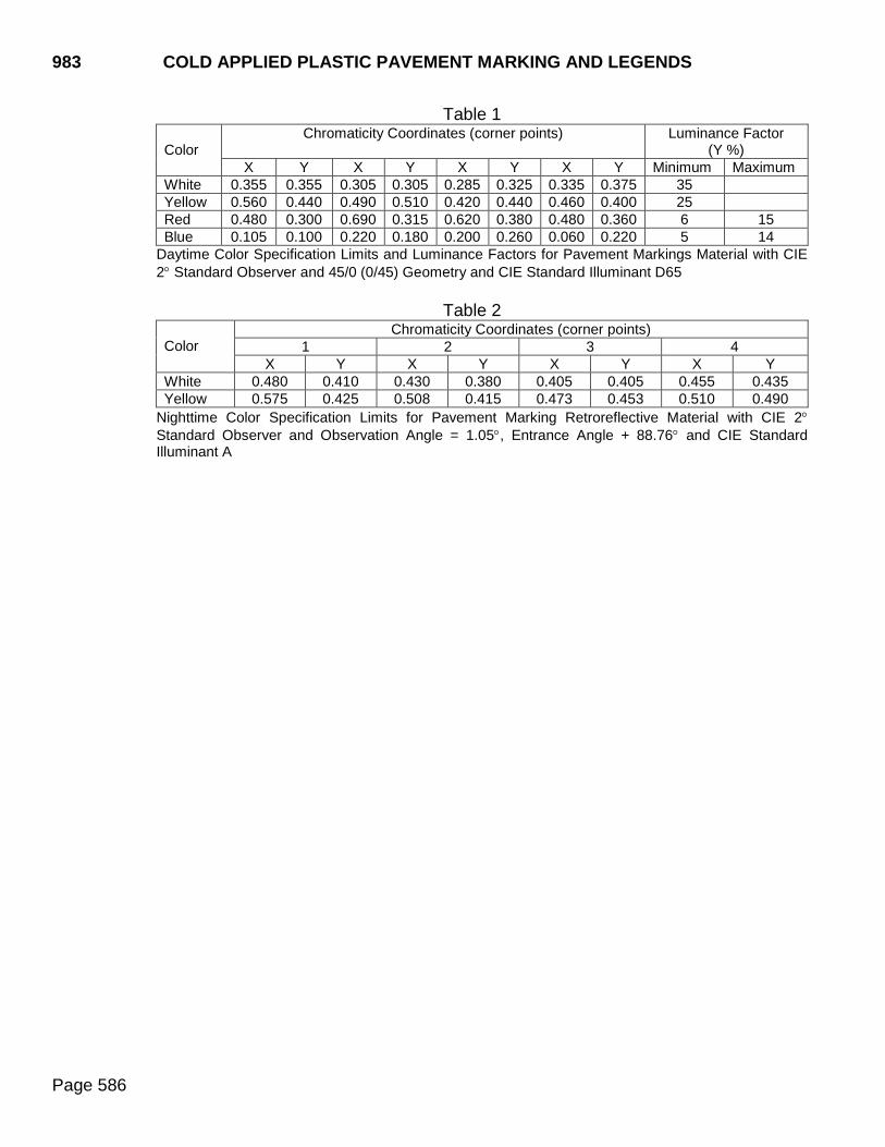
983 COLD APPLIED PLASTIC PAVEMENT MARKING AND LEGENDS
Page 586
Table 1 Color
Chromaticity Coordinates (corner points) Luminance Factor (Y %)
X Y X Y X Y X Y Minimum Maximum White 0.355 0.355 0.305 0.305 0.285 0.325 0.335 0.375 35 Yellow 0.560 0.440 0.490 0.510 0.420 0.440 0.460 0.400 25 Red 0.480 0.300 0.690 0.315 0.620 0.380 0.480 0.360 6 15 Blue 0.105 0.100 0.220 0.180 0.200 0.260 0.060 0.220 5 14
Daytime Color Specification Limits and Luminance Factors for Pavement Markings Material with CIE 2° Standard Observer and 45/0 (0/45) Geometry and CIE Standard Illuminant D65
Table 2
Color
Chromaticity Coordinates (corner points) 1 2 3 4
X Y X Y X Y X Y White 0.480 0.410 0.430 0.380 0.405 0.405 0.455 0.435 Yellow 0.575 0.425 0.508 0.415 0.473 0.453 0.510 0.490
Nighttime Color Specification Limits for Pavement Marking Retroreflective Material with CIE 2° Standard Observer and Observation Angle = 1.05°, Entrance Angle + 88.76° and CIE Standard Illuminant A
TEMPORARY TRAFFIC CONTROL DEVICES 984
Page 587
984.1 GENERAL Work zone traffic control devices, including signs, drums, cones, tubular markers, barricades, vertical panels, and direction indicator barricades shall be reflectorized with super/very high intensity sheeting applied to a satisfactory backing. Super/very high intensity is defined as that which meets the standards of Type XI as defined by AASHTO M 268 (ASTM D4956). Orange colored material shall be fluorescent.
984.2 FABRICATION
A. Background Color: The background color shall be as specified in Part 6 of the MUTCD.
B. Legend: Message and borders shall be non-removable copy of the color specified in
Part 6 of the MUTCD. The non-removable copy may be screened processed or direct applied. Mounting holes will not be drilled or punched in any part of the non-removable copy.
1. Screened Process: Message borders shall be processed on reflective sheeting
using mechanical equipment, materials, and operational methods and procedures as prescribed by the manufacturer. Processing shall be accomplished by the direct or reverse screen method using opaque or transparent processing material. Screening may be accomplished either before or after application of the sheeting to the base panels. Free hand painting will not be permitted on any part of the finished sign face.
2. Direct Applied: Cut out message and borders shall be reflective sheeting or opaque
lettering film applied directly to clean, dust free, reflective sheeting background. Message and borders shall be in accordance with the operational methods and procedures prescribed by the sheeting manufacturer. The finished letters, numerals, symbols, and borders shall be cut with smooth, regular outline, and free from ragged or torn edges.
984.3 TRAFFIC CONTROL DEVICE STANDARDS
A. Warning Lights: Warning lights shall be portable with lens directed enclosed lights.
The lens of the unit shall not be less than 7 inches in diameter and shall be amber in color. They may be used in either the steady burn or flashing mode. Warning lights shall be in accordance with the requirements of Equipment and Materials Standards of the Institute of Transportation Engineers (ITE) Publication No. ST 017, Purchase Specification for Flashing and Steady-Burn Warning Lights. The lights shall be certified by the manufacturer. The use of the warning lights shall be in accordance with Part 6 of the MUTCD.
B. Channelizing Devices: Channelizing devices, including cones, barricades, tubular markers, vertical panels, directional indicator barricades, and drums shall conform to the

984 TEMPORARY TRAFFIC CONTROL DEVICES
Page 588
requirements of Part 6 of the MUTCD. Drums shall be of a two part construction with breakaway bases.
C. Temporary Sign Supports: Construction sign supports shall meet the crashworthy
requirements of test level 3 of National Cooperative Highway Research Program (NCHRP) Report 350 or AASHTO Manual for Assessing Safety Hardware (MASH) and shall conform to the height requirements of the MUTCD.
D. Pilot Car: Pilot cars shall be a passenger car, multipurpose passenger vehicle, or pickup truck.
E. Temporary Pavement Marking Tape: Temporary pavement marking tape, Types I and
II, shall conform to the requirements of ASTM D4592. The film, without adhesive, shall have a minimum thickness of 39 mils.
F. Temporary Raised Pavement Markers: Temporary raised pavement markers shall
consist of a yellow or white plastic body providing a horizontal width and length of approximately 4 inches in both dimensions and approximately 3/4 inch high. The adhesive shall be resistant to the effects of weather and capable of retaining the marker in position during the time it is required to function. The markers shall consist of a methyl methacrylate, polycarbonate, polystyrene, or suitably compounded acrylonitrile butadiene (ABS) shell fitted with retroreflective lenses. The exterior surface shall be smooth. The marker reflector shall have a minimum coefficient of (retroreflected) luminous intensity conforming to Table 1.
G. Flexible Vertical Markers (Tabs): Flexible vertical markers (tabs) shall consist of a yellow or white plastic body providing a horizontal width of approximately 4 inches and approximately 2 inches high.
A strip of retroreflective tape 1/4 inch minimum width shall be bonded horizontally along the top of the vertical area. The adhesive shall be resistant to the effects of weather and capable of retaining the marker in position during the time it is required to function. The marker reflector shall have a minimum coefficient of (retroreflected) luminous intensity conforming to Table 1.
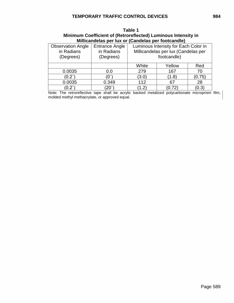
TEMPORARY TRAFFIC CONTROL DEVICES 984
Page 589
Table 1 Minimum Coefficient of (Retroreflected) Luminous Intensity in
Millicandelas per lux or (Candelas per footcandle) Observation Angle
in Radians (Degrees)
Entrance Angle in Radians (Degrees)
Luminous Intensity for Each Color in Millicandelas per lux (Candelas per
footcandle)
White Yellow Red 0.0035 0.0 279 167 70 (0.2˚) (0˚) (3.0) (1.8) (0.75)
0.0035 0.349 112 67 28 (0.2˚) (20˚) (1.2) (0.72) (0.3)
Note: The retroreflective tape shall be acrylic backed metalized polycarbonate microprism film, molded methyl methacrylate, or approved equal.
985 TRAFFIC SIGNALS AND ROADWAY LIGHTING
Page 590
985.1 REQUIREMENTS Prior to fabrication, the Contractor shall submit shop plans or catalog cuts for all signal equipment and luminaires to the Department for the Department’s review and approval. The Contractor shall send an email with the shop plans and catalog cuts attached as a PDF to the Project Engineer and the Office of Road Design. Upon request, the Project Engineer will provide the Contractor the appropriate email addresses. The Contractor shall not begin fabrication prior to the Department’s review and final approval of shop plans or catalog cuts. Within 14 calendar days of receiving the initial shop plans, the Office of Road Design will send a response with the Department’s final approval or one reviewed copy of the shop plans to the Contractor and submitter with changes to the design marked. The Contractor will make the necessary changes, if any, to the shop plans. The Contractor will then send the Project Engineer and the Office of Road Design an email with the final shop plans as a PDF for distribution. A. Electrical Grounding and Bonding:
1. Grounding Wire: Grounding wire from electrical cabinets to the ground rod shall be
bare, soft drawn copper, size per NEC. Grounding wire from pole to ground rod shall be bare, soft drawn copper, minimum size #6 AWG.
2. Bonding Conductors: Bonding conductors shall be of the same size and insulation
grade as the associated circuit conductors. Equipment grounding conductors shall be sized in compliance with the NEC.
3. Ground Rods: Ground rods shall be copper-coated electrodes in accordance with
Underwriters Laboratory (UL). The size and length shall conform to NEC requirements.
B. Conduit:
1. Rigid Steel Conduit: Conduit and fittings shall meet the requirements of UL 6 and
514 and shall be hot dip galvanized. Each section of conduit shall bear the UL label.
2. Rigid Nonmetallic Conduit: Conduit and fittings shall be polyvinyl chloride heavy wall meeting the requirements of UL 651 and 514. Use and installation of polyvinyl chloride (PVC) schedule 40 and 80 shall be in accordance with NEC and each section shall bear the UL label. When nonmetallic conduit is used in areas subject to vehicular traffic, the nonmetallic conduit shall be schedule 80.
C. Junction Boxes: Surface mounted junction boxes shall comply with NEMA 4X
stainless steel, shall be UL-listed, and, at a minimum, shall be sized according to the NEC. Stainless steel junction boxes shall have the cover held in place with a continuous hinge and kept closed with screws and clamps on the remaining three sides. The cover shall be removable by removing the pin with the continuous hinge. All seams shall be continuously welded. Gaskets shall be closed cell neoprene.
TRAFFIC SIGNALS AND ROADWAY LIGHTING 985
Page 591
D. Concrete Footings: Concrete for footings shall meet the requirements for Class M6 concrete. Cement shall be Type II. Vertical reinforcement shall be deformed unless otherwise noted and shall conform to the requirements of ASTM A615/AASHTO M 31 Grade 60. Circular ties, stirrups, and spiral reinforcing may be fabricated from deformed bars conforming to the requirements of ASTM A615/AASHTO M 31 Grade 60. Spiral reinforcing may also be fabricated from cold drawn wire conforming to ASTM A1064 or hot rolled plain bars conforming to ASTM A615/AASHTO M 31 Grade 60.
E. Anchor Bolts and Anchor Rods: Anchor bolts and anchor rods shall conform to
Section 972.
F. Electrical Power Cables: Electrical cables shall be Type THW, THWN, XLPE, or XHHW rated for 600 volts AC and be clearly and durably marked with the UL label, type of insulation, number of conductors, and the AWG size. Traffic signals and traffic signals with intersection lighting using the same service cabinet shall utilize stranded copper meeting the requirements of ASTM B3 and B8, Class C. Roadway lighting shall utilize stranded copper conductors for service, feeder, and branch circuits.
1. Direct Burial Cable :
a. Cables shall be made up of single or multiple conductors and shall meet the
applicable requirements of ICEA/NEMA Standards or applicable UL standards.
b. When underground armored cable is specified, multiple conductor cable shall be provided with bronze tape armor meeting the requirements of ASTM B130, with a minimum thickness of 10 mils and a spiral overlap of not less than 1/4 inch.
c. The multiconductor cable shall be either cross linked or butyl insulated.
2. Pole and Bracket Cable:
a. The cable from pole base to luminaire shall be two-conductor of the AWG size
shown, meeting ICEA Standards.
b. Conductors shall be THWN/THNN meeting ASTM B3. Conductors shall be stranded bare soft copper meeting ASTM B3 and B8, Class C. Each conductor shall be insulated with high dielectric strength heat and moisture resistant PVC rated for use at 75ºC, and shall meet the requirements of ICEA. One insulated conductor shall be colored white and the other black. The two insulated conductors shall be laid parallel and covered with a black polyethylene belt. The belt shall meet the requirements of ICEA.
985 TRAFFIC SIGNALS AND ROADWAY LIGHTING
Page 592
G. Traffic Signal Control Cables:
1. Multiple Conductor Cables: Shall be THHN/THWN insulated conductors with fillers of nonabsorbent material, bound with polyester tape and with a PVC jacket. Two-conductor cables may either be of round or flat construction.
2. Conductors: Shall be Class C stranded copper meeting the requirements of ASTM
B3 and B8.
3. Insulation: Insulation shall have a minimum thickness of 19 mils of which 15 mils shall be PVC with the remaining thickness of nylon.
4. Colors: Conductor insulation shall be colored in accordance with ICEA.
5. Jackets: Jackets shall be PVC meeting UL requirements for Class 12 jackets and
ICEA standards.
6. Markings: The cable shall be marked with the name of the manufacturer, rated voltage, UL label, AWG size, and number of conductors.
H. Electrical Service Cabinet:
1. Shall be a NEMA Type 3R enclosure.
2. Size shall be as required to house required components.
3. Shall be rated for service entrance equipment.
4. Required components:
a. Main breaker.
b. A copper bus rated for the voltage, current, and phases required by the plans.
c. Branch circuit breakers meeting plan requirements for amps, voltage, and
phases. Minimum A.I.C. shall be 10,000.
d. When plans require, a mechanically held contactor, NEMA rated for the load served, shall be provided. The contactor shall be encased in a UL approved weatherproof housing with an integral test switch included. The contactor shall be complete with an interface relay for photocell control and photocell bypass switch. A photocell shall be provided.
TRAFFIC SIGNALS AND ROADWAY LIGHTING 985
Page 593
I. Traffic Signal Poles:
1. Design:
a. The location, number, area, and weight of the signal heads and signing as shown on the plan detail plates shall be used for determination of adequate pole and footing structural design. The actual quantity and locations of signal heads shall be as shown on the plan sheet.
b. Design and fabrication shall be in accordance with the current edition of the
AASHTO Standard Specifications for Structural Supports for Highway Signs, Luminaires, and Traffic Signals, including all subsequent interims and plan details.
c. Wind load shall be calculated using the 50 year mean recurrent interval basic
wind speed.
d. New poles shall be galvanized steel. Galvanizing shall be in accordance with AASHTO M 111 (ASTM A123). Steel pole material shall be in accordance with ASTM A36, A242, A570, A572, A607, A709, A1008, A1011, or A595 Grade A or B. A595 material shall be limited to a 3/8 inch maximum thickness. Steel pole material with a thickness of 1/2 inch to 2 inches, shall satisfy Charpy V-Notch toughness test requirements of 15 foot pounds at 40oF. The SDDOT Office of Bridge Design shall be contacted for Charpy impact requirements for steel pole material thickness greater than 2 inches.
e. The steel pole-to-base-plate connection shall be a full-penetration groove-welded
connection with a backing ring as described in the AASHTO Standard Specifications for Structural Supports for Highway Signs, Luminaires, and Traffic Signals.
f. The design yield strength shall be no higher than 55,000 psi. Strength of steel for
fabricating poles may be higher than 55,000 psi, but not lower than 36,000 psi.
g. Anchor bolt or rod circle, anchor bolt or rod size, and other structural properties of the pole and base are to be designed and determined by the pole manufacturer.
h. Connections at the base of the pole shall be made with water tight connectors
approved for outdoor use.
i. Pole designs must provide for drainage with no laps or edges to hold moisture.
j. Mast arm pole shafts shall have a removable cover and an opening for cable entrance to the mast arm.
k. A "J" hook for a cable strain relief grip or other strain relief device shall be
provided at the top of the pole or electrical fixture.
985 TRAFFIC SIGNALS AND ROADWAY LIGHTING
Page 594
l. Luminaire extensions shall meet specifications for roadway luminaire poles.
m. Hand holes and other openings shall be smooth, neat, and covered.
2. Certification: A statement is required, signed by a Professional Engineer registered
in the state of South Dakota, certifying the pole designs meet all plan and specification requirements.
3. Shop Plans: Prior to fabrication, the Contractor shall submit shop plans or catalog
cuts for the traffic signal poles to the Department for the Department’s review and approval. The Contractor shall send an email with the shop plans and catalog cuts attached as a PDF to the Project Engineer and the Office of Road Design. Upon request, the Project Engineer will provide the Contractor the appropriate email addresses. The Contractor shall submit comprehensive design calculations for the traffic signal poles, including anchor bolts, signed and sealed by a SD registered Professional Engineer with the shop plans. The Contractor shall not begin fabrication prior to the Department’s review and final approval of shop plans or catalog cuts. Within 2 weeks of receiving the initial shop plans, the Office of Road Design will send a response with the Department’s final approval or one reviewed copy of the shop plans to the Contractor and submitter with changes to the design marked. The Contractor will make the necessary changes, if any, to the shop plans. The Contractor will then send the Project Engineer and the Office of Road Design an email with the final shop plans as a PDF for distribution.
J. Roadway Luminaire Poles:
1. Design:
a. Design and fabrication shall be in accordance with the current edition of the
AASHTO Standard Specifications for Structural Supports for Highway Signs, Luminaires, and Traffic Signals, including all subsequent interims and plan details.
b. Wind load shall be calculated using the 50 year mean recurrent interval basic
wind speed.
c. New poles shall be galvanized steel. Galvanizing shall be in accordance with AASHTO M 111 (ASTM A123). Steel pole material shall be in accordance with ASTM A36, A242, A570, A572, A607, A709, A1008, A1011, or A595 Grade A or B. A595 material shall be limited to a 3/8 inch maximum thickness. Steel pole material with a thickness of 1/2 inch to 2 inches, shall satisfy Charpy V-Notch toughness test requirements of 15 foot pounds at 40oF. The SDDOT Office of Bridge Design shall be contacted for Charpy impact requirements for steel pole material thickness greater than 2 inches.
d. The steel pole-to-base-plate connection shall be a full-penetration groove-welded
connection with a backing ring as described in the AASHTO Standard
TRAFFIC SIGNALS AND ROADWAY LIGHTING 985
Page 595
Specifications for Structural Supports for Highway Signs, Luminaires, and Traffic Signals.
e. The design yield strength for steel shall be no higher than 55,000 psi. Yield
strength of the steel used in fabricating poles may be higher than 55,000 psi but shall not be lower than 36,000 psi.
f. All poles shall have breakaway transformer bases.
g. Anchor bolt or rod circle, anchor bolt or rod size, and other structural properties
of the pole and base are to be designed and determined by the pole manufacturer.
h. Connections at the base of the pole shall be made with water tight connectors
approved for outdoor use.
i. Pole designs must provide for drainage with no laps or edges to hold moisture.
j. Mast arm pole shafts shall have a removable cover and an opening for cable entrance to the mast arm.
k. A "J" hook for a cable strain relief grip or other strain relief device shall be
provided at the top of the pole or electrical fixture.
l. Hand holes and other openings shall be smooth, neat, and covered.
2. Certification: A statement is required, signed by a Professional Engineer registered in the state of South Dakota, certifying the pole designs meet all plan and specification requirements, including breakaway and structural adequacy, of the AASHTO Specifications for Structural Supports for Highway Signs, Luminaires, and Traffic Signals. The physical testing procedures outlined in the Aluminum Association’s Specifications for Aluminum Structures may be used to establish service limits for structural adequacy certification of aluminum breakaway transformer bases and frangible couplings. If requested, test data of production samples to support the certification shall be provided.
3. Shop Plans: Prior to fabrication, the Contractor shall submit shop plans or catalog
cuts for the roadway luminaire poles to the Department for the Department’s review and approval. The Contractor shall send an email with the shop plans and catalog cuts attached as a PDF to the Project Engineer and the Office of Road Design. Upon request, the Project Engineer will provide the Contractor the appropriate email addresses. The Contractor shall submit comprehensive design calculations for the roadway luminaire poles, including anchor bolts or rods, signed and sealed by a SD registered Professional Engineer with the shop plans. The Contractor shall not begin fabrication prior to the Department’s review and final approval of shop plans or catalog cuts. Within 14 calendar days of receiving the initial shop plans, the Office of Road Design will send a response with the Department’s final approval or one reviewed copy of the shop plans to the Contractor and submitter with changes to the
985 TRAFFIC SIGNALS AND ROADWAY LIGHTING
Page 596
design marked. The Contractor will make the necessary changes, if any, to the shop plans. The Contractor will then send the Project Engineer and the Office of Road Design an email with the final shop plans as a PDF for distribution.
K. Luminaires:
1. Must be a complete lighting device, weatherproof, with cast aluminum housing,
reflector, refractor, lamp, lamp socket, terminal block, integral ballast, and with internal parts readily accessible.
2. Mounting must be by a 2 inch slipfitter (except for wall mounts) unless otherwise
noted in the plans.
3. Refractor shall be constructed of clear, heat and shock resistant glass, or a material which gives similar light transmission with shock resistance.
4. Ballast shall be constant wattage and multiple voltage.
L. Light Towers:
1. Design:
a. Design and fabrication shall be in accordance with the current edition of the
AASHTO Standard Specifications for Structural Supports for Highway Signs, Luminaires, and Traffic Signals, including all subsequent interims and plan details. Light towers, including anchor bolts or rods, shall be designed for fatigue in accordance with Fatigue Importance Category I.
b. Wind load shall be calculated using the 50 year mean recurrent interval basic
wind speed.
c. New towers shall be galvanized steel. Galvanizing shall be in accordance with AASHTO M 111 (ASTM A123). Steel tower material shall be in accordance with ASTM A36, A242, A570, A572, A607, A709, A1008, A1011, or A595 Grade A or B. A595 material shall be limited to a 3/8 inch maximum thickness. Steel tower material with a thickness of 1/2 inch to 2 inches, shall satisfy Charpy V-Notch toughness test requirements of 15 foot pounds at 40oF. The SDDOT Office of Bridge Design shall be contacted for Charpy impact requirements for steel tower material thickness greater than 2 inches.
d. The steel pole-to-base-plate connection shall be a full-penetration groove-welded
connection with a backing ring as described in the AASHTO Standard Specifications for Structural Supports for Highway Signs, Luminaires, and Traffic Signals.
e. The design yield strength for steel shall be no higher than 55,000 psi Yield
strength of the steel used in fabricating poles may be higher than 55,000 psi but shall not be lower than 36,000 psi.
TRAFFIC SIGNALS AND ROADWAY LIGHTING 985
Page 597
f. Anchor bolt or rod circle, anchor bolt or rod size, and other structural properties
of the pole and base are to be designed and determined by the pole manufacturer.
g. Connections at the base of the pole shall be made with water tight connectors
approved for outdoor use.
h. Pole designs must provide for drainage with no laps or edges to hold moisture.
i. Hand holes and other openings shall be smooth, neat, and covered.
2. Lowering Devices: The manufacturer shall furnish a factory respresentative to assist the Contractor with the assembly of the first lowering system into the pole assembly, and they shall furnish the Contractor with written installation and operational instructions.
a. Nonlatching Type: The lowering system shall be a two-cable hoisting system
consisting of a stainless steel head assembly, stainless steel luminaire ring and junction box, stainless steel winch drums and corrosion-resistant winching system, and a portable power unit.
The power cord shall be Type W, with four #8 conductors and a 30 amp, 600 volt twist-lock weatherproof male connector. The power cable shall be tethered between the hoisting cables with a stainless steel harness.
The head assembly shall be manufactured of stainless steel and shall consist of a formed channel bolted to the top of the pole shaft with four stainless steel bolts, nuts, and lockwashers. The channel shall support four cable sheaves 6 inches in diameter with a special cable keeper to ensure proper cable guidance and two pilot guides to secure the horizontal position of the luminaire ring. The power cable sheave shall be made of cast aluminum with a minimum diameter of 16 inches. All sheaves shall have permanently lubricated bronze bearings and stainless steel axle pins. A cable keeper shall be provided to prevent the power cable from working out of the sheave.
The luminaire ring assembly shall be fabricated of stainless steel and consist of the luminaire ring, hoisting cable terminator tubes, and a weather proof junction box. The inner portion of the ring shall be equipped with a PVC shock absorbing tube protecting the pole and luminaires during the raising-lowering operation. The ring shall be supplied with stainless steel tenons for the required number of luminaires. The power cord shall terminate into the luminaire ring by a deluxe Kellems grip. The luminaire ring shall be a totally enclosed wire way.
The ring shall be raised, supported, and lowered by two 1/4 inch stainless steel 7x19 strand cables, each with a hoisting strength of 6000 pounds. The two hoisting cables shall be continuous from the luminaire ring to the winch drum and of sufficient length to be two times the length of the pole shaft plus 20 feet.
985 TRAFFIC SIGNALS AND ROADWAY LIGHTING
Page 598
The luminaire assembly shall be held firmly to the masthead assembly by two compression springs at the end of the hoisting cables and within the stainless steel support cable terminal tubes. The springs shall compress to hold the weight of the luminaire ring assembly and the luminaires plus 300 pounds.
The winch assembly shall consist of a worm gear speed reducer with a ratio of 72:1. The worm gear housing shall be of cast aluminum or other corrosion resistant material. The assembly shall also consist of a double output shaft and two stainless steel drums with calibrated adjustable clutches which compensate for the cable winding of both drums. The double output shaft shall be supported by two stainless steel outboard bearing assemblies. The input or drive pulley shall be equipped with a double brake shoe to serve as a safety brake when either the motor drive belt or the motor is removed. Raising speed of the luminaire ring shall be a minimum of 12 feet per minute.
The portable motor power unit shall consist of a TEFC NEMA 56 C face motor, 240 volt reversible with a magnetic brake attached. It shall be mounted to the winch with an internal bracket and a V-drive belt. The motor shall be equipped with a power cord and a weatherproof connector to mate with the power supply cord connector. The motor shall be operated by a push button control on a 20 foot long extension cord. Two stainless steel chains and grippers shall secure the hoisting cables to the base of the pole while in the static load position. The ultimate support of the luminaire ring shall not be dependent upon the winch assembly or have latches at the top of the pole or in the masthead assembly.
b. Latching Type: The lowering device shall consist of a head frame assembly, a
luminaire ring assembly, and a winch assembly.
The luminaire ring shall latch to the head frame assembly to eliminate strain on hoisting cables when the lowering device is not in operation. Latches shall be of a cam-action type, with no moving parts or springs attached to the head frame assembly. The luminaire ring shall not move laterally or rotate during the latching or unlatching process, imparting lateral g forces on the luminaire. The power cable shall be guided over a roller assembly when lowering or raising the luminaire ring. The luminaire ring shall employ roller contact, spring loaded centering arms to keep the ring concentric with the pole in winds up to 30 MPH. The arms shall be interconnected and loaded with stainless steel springs to uniformly apply equal centering force when any one has been actuated. The winch assembly shall be prewound with 1/4 inch diameter 7x19 stainless steel aircraft cord and shall be supported at both ends. Keepers shall be provided to ensure uncoiled cable will rewrap onto the drum.
TRAFFIC SIGNALS AND ROADWAY LIGHTING 985
Page 599
The portable power unit shall be a heavy duty reversing type with a stalling torque at least twice that required to operate the device, and shall be controlled by a reversing switch with a 20 foot cord.
3. Certification: A statement is required, signed by a Professional Engineer registered
in the state of South Dakota, certifying the light tower designs meet all plan and specification requirements.
4. Shop Plans: Prior to fabrication, the Contractor shall submit shop plans or catalog
cuts for the light towers to the Department for the Department’s review and approval. The Contractor shall send an email with the shop plans and catalog cuts attached as a PDF to the Project Engineer and the Office of Road Design. Upon request, the Project Engineer will provide the Contractor the appropriate email addresses. The Contractor shall submit comprehensive design calculations for the light towers, including anchor bolts or rods, signed and sealed by a SD registered Professional Engineer with the shop plans. The Contractor shall not begin fabrication prior to the Department’s review and final approval of shop plans or catalog cuts. Within 14 calendar days of receiving the initial shop plans, the Office of Road Design will send a response with the Department’s final approval or one reviewed copy of the shop plans to the Contractor and submitter with changes to the design marked. The Contractor will make the necessary changes, if any, to the shop plans. The Contractor will then send the Project Engineer and the Office of Road Design an email with the final shop plans as a PDF for distribution.
M. Photoelectric Control Requirements: Photoelectric controls shall be one of the
photoelectric controls listed on the Department’s Approved Products List.
N. Controller Cabinet: The controller cabinet shall be NEMA compliant.
1. Cabinet Design:
a. The cabinet shall be made of welded sheet aluminum. b. The type and size of cabinets shall be determined by the signal controller
supplier. The cabinet shall be of sufficient size to accommodate the controller and associated equipment.
c. The cabinet shall be furnished with a hinged door that provides complete access
to the cabinet interior. The controller cabinet door shall be hinged on the right side. The door shall have a gasket making a weatherproof and dust tight seal. The door shall be provided with a lock and two standard keys. Base mounted cabinets shall be furnished with doorstops to hold the door open during servicing.
d. The cabinet door shall contain a police panel with a lock and key. The police
panel shall contain two switches. One switch shall be designated "flash/normal" and the other switch designated "signal off/on". At any switch position, power shall be maintained for all control equipment, including detector amplifier units,
985 TRAFFIC SIGNALS AND ROADWAY LIGHTING
Page 600
within the cabinet. The switch shall be labeled and rated for the current load. Switch terminals on the rear of the police panel shall be insulated so live parts are not exposed.
e. The controller cabinet shall be a NEMA Type 3R Enclosure.
f. Underside mounted LED light strips shall be installed on each shelf in the
controller cabinet. An on/off switch that is turned on when the cabinet door is opened and turned off when the cabinet door is closed shall activate the lights. The switch shall be wired to place an input to the signal controller event or alarm log when the cabinet door is opened. The power supply for the LED light strips shall be separate from the standard double plug receptacle.
g. The controller cabinets shall be capable of placing vehicle and pedestrian calls
into the controller. Placed calls shall provide for eight vehicle phases and four pedestrian phases. The placed calls for vehicle phases shall be capable of extending the associated vehicle phase by continuous or intermittent contact.
2. Fan Assembly: Cabinets shall be provided with thermostatically controlled fan vent
assemblies. The thermostat shall be adjustable within a range from 75ºF to 150ºF and shall be separately fused. A screened and filtered air intake area of at least 12 square inches shall be provided. The filters shall be removable, cleanable, reusable, and replaceable.
3. Electrical:
a. A three wire 15 ampere NEMA standard double plug receptacle with ground
contact shall be wired as a separate circuit ahead of the main breaker.
b. A main circuit breaker shall be furnished and installed in the controller cabinet. An auxiliary circuit breaker shall be provided and connected to the load side of the main breaker. The main breaker shall be wired to protect the signal load and controller circuits. The auxiliary circuit breaker shall be properly rated and fused to protect circuits utilizing unfiltered AC power. Terminal facilities in the cabinet for incoming AC power will be protected to prevent short-circuiting when working with tools in the cabinet. The circuit breakers shall be capable of manual operation with markings to indicate ratings and whether it is in the open or closed position.
c. A power line filter certified in accordance with UL Standard 1283 and meeting the
following specifications shall be installed at the main breaker:
1) 50 db minimum attenuation over a frequency range of 200 kilohertz to 75 kilohertz.
2) Minimum feed through current of 30 amperes at 120 volts, 60 hertz.
TRAFFIC SIGNALS AND ROADWAY LIGHTING 985
Page 601
d. The cabinet shall be equipped with a surge protection device certified in accordance with UL Standard 1449 and meeting the following specifications:
1) Nominal discharge current rating of 3kA.
2) Voltage protection rating 330V.
e. Bus bar terminals such as AC common (neutral), AC power, safety (chassis)
ground and AC signal power shall be furnished and properly installed.
f. Terminals and panel wiring for detector leads, interconnect, time switches, relays, load switch sockets, flash transfer relay sockets, and any other components required to provide the controller operation shall be installed.
g. Terminals and components that make up the basic terminal facilities shall be
permanently identified in accordance with the cabinet wiring diagram. Identification shall be permanently attached as close as possible to the terminal or component and shall not be affixed to any part which is easily removed.
h. Each input or output terminated on a terminal block shall be identified on the front
of the panel by a position number and functional terminology (e.g. 0/1 Red, 0/2 Hold, Channel 3 Red, etc.). The same identification shall be used consistently on the cabinet wiring diagram.
i. Each component shall be identified on the front of the panel by a symbol and
function terminology consistent with the cabinet wiring diagram. Provisions shall be made that each load switch socket can be identified by the phase or overlap number by writing on the panel in an area established for this feature.
j. Panel wiring shall be neat and firm with panel mounted terminals for signal lamp
circuit conductors, one for each signal circuit, and one or more terminals for the common conductor. The terminals shall be located a minimum of 3 inches from the bottom of the cabinet and arranged for adequate clearance between the terminals. The controller equipment and terminals shall be arranged within the cabinet so they will not upset the entrance, training, and connection of incoming conductors.
k. A flasher socket and a solid state flasher meeting current NEMA standards shall
be provided in the controller cabinet.
O. Controller: The controller shall be a solid state, digital, NEMA TS2 Type 1 from the Department’s Approved Products List and as approved by the South Dakota Department of Transportation Traffic Design Engineer in the Office of Road Design. The controller shall have front panel access to display cycle length, offset, and internal timing values. Access to these timing functions shall be by keyboard entry as an integral part of the controller. The controller shall meet NEMA environmental and electrical performance standards. The controller shall also have a USB port and an Ethernet port.
985 TRAFFIC SIGNALS AND ROADWAY LIGHTING
Page 602
The controller shall be two through twelve phase controllers. Digital timing shall be provided with a battery backup. The controller shall be capable of programming by manual entry via the front panel keyboard, data downloading from a portable PC computer via null-modem cable, data downloading from one controller to another using a serial port on each controller, and restoring data using a data transfer module (data key). In a closed-loop system, the controller shall be capable of data downloading via telemetry. In an enterprise system, the controller shall be capable of data downloading from a central server. The controllers shall be capable of operating coordinated by time-based, hardwire, and telemetry. The controllers shall have a copy function to copy all timing data from one phase to another. The controllers shall also permit copying all coordination pattern data from one pattern to another. Hardware for future pedestrian signals shall be provided when shown. The controller shall be equipped with solid state signal load switching devices meeting current NEMA requirements. Load switches shall be furnished with input and output indicator lights on the front panel. The interface panels shall be capable of inserting up to sixteen load switches. Each controller shall be furnished with a malfunction management unit (MMU) conforming to the requirements of NEMA Standard TS-2 Section 4. The provided MMU shall have visual displays for programming and operational purposes. A sufficient quantity of BUS Interface Units shall be installed in the cabinet to provide communication between detectors, load switches, controller unit, etc. Each BUS Interface Unit shall conform to NEMA Standard TS-2, Section 8. The controller shall be furnished with extra feature wiring to provide for remote flashing and each wire shall have its own terminal connection. The flash control circuit shall ensure that remote transfer to flashing from normal stop and go operations occurs during the end of the mainline green interval in the cycle. When the controller is in a flashing condition, the signal switching mechanism shall be inoperative. The controller time of day flash shall alternate the red and yellow indication with yellow on the major route and red on the minor route. The controller malfunction flash shall be red-red. Load switches for pedestrian indications shall be required when pedestrian indications are shown. The cabinet wiring, load switch sockets, and connection facilities shall be included for pedestrian movements permissible with phasing shown.
TRAFFIC SIGNALS AND ROADWAY LIGHTING 985
Page 603
The controller shall have internal signal dimming. The controller solid state flasher shall have dimming capability. Initial signal activation shall be done by a manufacturer trained technician. The technician shall be on-site for at least two consecutive days.
The controller furnished shall meet current NTCIP requirements.
P. Detector Unit: Components and workmanship shall conform to the standards of NEMA.
Detector units shall include a visual display screen in the controller cabinet.
Q. Detector Loops:
1. Lead-in (Home Run) Wires: Feeder wires from loop leads to detector units shall be twisted shielded pairs, Belden Number 8719, or equal, #16 AWG minimum size. Splices are to be avoided in feeder wires.
2. Sawed-in Loops:
a. Conductors shall conform to the following requirements:
Material Stranded Copper
Size #16 AWG (Minimum) Insulation
XHHW, THHN, RHH, or RHW Encasement 1/4 inch Polyethylene tubing
b. Backer rod material shall be resilient, nonabsorbent material approximately 25%
larger in diameter than the width of the sawed slot to be sealed.
c. Loop Sealants: Shall be one of the products as listed on the Department’s Approved Products List.
3. Preformed Loops: Conductors shall conform to the following requirements:
Material Stranded Copper Size #16 AWG (minimum) Insulation 600 Volt, XLP, bearing the U.L. designation
for either Type RHH and RHW or Type XHHW
R. Signal Heads:
1. All vehicle and pedestrian signal indications shall be light emitting diode (LED) signal
modules.
985 TRAFFIC SIGNALS AND ROADWAY LIGHTING
Page 604
2. Vehicular signal indications shall meet the requirements of the Institute of Transportation Engineers (ITE) Standard, Vehicle Traffic Control Signal Heads.
3. Pedestrian signal indications shall meet the requirements of the ITE Standard,
Pedestrian Traffic Control Signal Indicators.
4. The light intensity requirements of the ITE standard will not apply to vehicular and pedestrian signal indications for solar powered signal systems and the intensity shall be as approved by the Engineer or as specified in the plans.
5. The LED signal modules shall be warranted against defects in materials and
workmanship for a period of 36 months after the installation of the modules. The manufacturer shall provide this warranty in writing to the Engineer prior to installation of the LED signal modules.
6. Size: Shall be a minimum of 12 inches diameter.
7. Color: Doors, visors, and backplates shall be dull black and housing highway yellow.
8. Material may be either cast aluminum or polycarbonate resin.
9. Visors shall be of the tunnel type.
10. Backplates for Signal Heads: Unless otherwise stated on the plans, signal backplates shall be 0.125 inch thick polycarbonate. The polycarbonate backplates must be made up from no more than two pieces.
S. Pedestrian Push Button: All pedestrian push buttons shall be compliant with the
Americans with Disabilities Act (ADA). Accessible pedestrian push buttons shall be one of the accessible pedestrian signals on the Department’s Approved Products List.
1. General:
a. Shall be pressure activated with essentially no moving parts.
b. Shall be vandal resistant.
c. Shall activate with 3 pounds force or less.
d. Shall have an LED that illuminates when the button is being pushed and remains illuminated until the pedestrian call is served.
e. Shall give a toned beep verification of button being pushed.
f. Shall have an operating life of 1 million actuations.
g. Shall be compatible with NEMA TS2 controllers.
TRAFFIC SIGNALS AND ROADWAY LIGHTING 985
Page 605
2. Housing:
a. Button housing shall be unfinished, high impact cast or machined aluminum.
b. All switch electronics shall be sealed within the high impact cast or machined aluminum housing.
c. Shall have a gasket between the button housing and the mounting cup.
3. Electrical:
a. Operating Voltage: 15 to 24V DC or 12 to 24V AC.
b. On Resistance 10 Ohms (when the button is activated and placing a call).
c. Standby Current 10 micro amps typical.
d. Shall have built in surge protection.
e. Shall have a solid state electronic piezo switch rated for 1 million cycles with no
moving plunger or moving electrical contacts.
f. Shall hold the call for a minimum of 5 seconds.
g. Requires only two conductors be run from the traffic signal cabinet to the push button to operate.
h. Six units wired in parallel on a single pedestrian isolator input shall not pull the
input voltage of the pedestrian isolator down such that a false pedestrian call is placed in the controller.
T. Flashing Beacons: Flashing beacons shall conform to Part 4 of the MUTCD and the
following: 1. Each signal indication shall have a visible diameter of not less than 12 inches. 2. All signal indications shall be LED type. The LED module shall be in accordance with
the requirements of the current performance specifications of the ITE.
3. When solar powered flashing beacons are specified in the plans, the solar powered flashing beacons shall be one of the products as listed on the Department’s Approved Products List or approved by the Engineer.
990 PIPE CULVERTS AND DRAINAGE TUBING
Page 606
990.1 REQUIREMENTS
A. Reinforced Concrete Pipe: Reinforced concrete pipe shall conform to AASHTO M 170, M 206, and M 207.
1. Basis of Acceptance: The acceptability of the pipe will be determined on the basis
of plant load bearing tests, compressive strength of concrete, material tests, and inspection of the complete product.
2. Materials: Materials shall conform to the requirement of the following sections:
a. Portland cement shall be Type II conforming to Section 750.
b. Water shall conform to Section 790.
c. Fine aggregate shall conform to Section 800.
d. Coarse aggregate shall conform to Section 820 except the gradation
requirements shall not apply.
e. Reinforcement shall conform to Section 1010.
f. Air entraining agent shall conform to Section 751. The entrained air content for wet cast pipe shall be 6% plus or minus 1.5%.
g. Fly ash shall conform to Section 753.
h. Flexible watertight gaskets shall conform to ASTM C990.
i. Admixtures shall conform to Section 752.
3. Concrete: The concrete in special sections shall have a minimum compressive
strength of 4000 psi. Special sections are those sections of concrete pipe not covered by the class requirement of AASHTO M 170, M 206, or M 207. The strength shall be determined by test cylinders or by cores.
B. Corrugated Metal Pipe: Corrugated metal pipe shall conform to AASHTO M 36 or AASHTO M 196.
C. Bituminous Coated Corrugated Metal Pipe: Bituminous coated corrugated metal pipe
shall conform to AASHTO M 190, except the pipe shall conform to AASHTO M 36 or AASHTO M 196 before coating.
D. Structural Plate Pipe: Structural plate for pipe shall conform to AASHTO M 167 or
AASHTO M 219.
PIPE CULVERTS AND DRAINAGE TUBING 990
Page 607
E. Corrugated Polyethylene Drainage Tubing: Corrugated polyethylene drainage tubing, couplings, and fittings shall conform to the requirements of AASHTO M 252 except Section 7.4 is modified as follows: The length of the individual slots on the 4 inch to 8 inch diameter tubing shall not exceed 12% of the tubing inside nominal circumference.
F. Corrugated Polyethylene Pipe: Corrugated polyethylene pipe, couplings, and fittings
shall conform to the requirements of AASHTO M 294.
G. High Density Polyethylene Pipe: High Density Polyethylene pipe, couplings, and fittings shall conform to the requirements of AASHTO M 294.
1010 CONCRETE REINFORCEMENT
Page 608
1010.1 REQUIREMENTS
A. Bar Reinforcement – Structures and Paving (excluding dowel and tie bars): Bar reinforcement for structures and concrete pavement, shall conform to the requirements of AASHTO M 31 (ASTM A615) Grade 60. Bar reinforcement shall be deformed, unless otherwise noted.
B. Welded Wire Reinforcement: Welded wire reinforcement shall conform to ASTM
A1064 including the optional yield strength measurement.
C. Tie Bars: Tie bars for concrete pavement shall conform to the requirements of AASHTO M 31, Grade 40, except rail steel shall not be used for tie bars that are to be bent and re-straightened. Tie bars shall be deformed. Tie bars shall be epoxy coated conforming to Section 1010.1 E. Sawing or shearing of the tie bars to obtain the specified length will be permitted provided the coating is not damaged and the resulting bar is free from burring and other deformations. The cut ends shall be coated.
D. PCC Paving Dowel Bars and Dowel Bar Assemblies: The steel cores of dowel bars and plain round bars shall be plain round bars conforming to AASHTO M 31 (ASTM A615) Grade 40 or 60, M 227 (ASTM A663) Grade 70 minimum, or M 255 (ASTM A675) Grade 75 minimum. The bars shall be the diameter shown in the plans, free from burring or other deformation restricting slippage in the concrete. Dowel bars shall be epoxy coated conforming to Section 1010.1 E. Sawing or shearing of the dowel bars will be permitted provided the coating is not damaged and the resulting bar is within the permissible deformations. The cut ends are not required to be coated. Any deformation larger than true shape shall not exceed a 0.04 inch increase in diameter or thickness and shall not extend more than 0.40 inch from the dowel end. Bond breakers used to pre-coat dowel bar assemblies shall be one of the products from the Department’s Approved Products List.
E. Epoxy Coated Reinforcement: A Certificate of Compliance and a copy of all quality control test results for the epoxy coating shall be furnished for each shipment supplied for use on a project. Dowel bars for concrete pavements shall be epoxy coated and shall conform to AASHTO M 254 Type B except the film thickness shall be from 5 to 13 mils after cure. All other epoxy coated reinforcement shall comply with ASTM A775.
F. Pretensioning Reinforcement: Pretensioning Reinforcement shall conform to AASHTO M 203 (ASTM A416) and shall be low-relaxation strands unless otherwise specified.
GABIONS 1030
Page 609
1030 GABIONS
Gabions shall be supplied in various lengths and heights. The lengths shall be multiples (2, 3, or 4) of the horizontal width. The heights shall be fractions (1, 1/2, or 1/3) of the horizontal width. The horizontal width shall not be less than 36 inches. Gabions shall be of uniform width. Gabions shall be fabricated so the sides, ends, lid, and diaphragms can be assembled at the construction site into a rectangular basket. Gabions shall be of single unit construction. Base, lid, ends, and sides shall be either woven into a single unit or one edge of these members connected to the base section of the gabion so strength and flexibility at the point of connection is at least equal to that of the mesh. The gabion shall be furnished with diaphragms the same mesh and gauge as the body of the gabions, secured in proper position on the base in such a manner that no additional tying at this juncture will be necessary. The spacing of the diaphragms shall be the same as the horizontal width.
All perimeter edges of the mesh forming the baskets, including end panels and top of the diaphragms, shall be selvedged with selvedge wire. For sound structural integrity, the gabion mesh wires shall be wrapped around the selvedge wire with a number of turns necessary to interconnect each of them with the adjacent mesh wire.
For multitiered structures, the internal connecting wires shall be furnished. The internal connecting wires shall meet the same specifications as the wire used in the mesh.
Tie wire or connecting wire shall securely fasten all edges of the gabion and diaphragms to provide for four internal connecting wires in each cell one-half unit high and eight internal wires in each cell one unit high. The tie wire shall meet the same specifications as the wire used in the mesh except that the tie wire may be two gauges smaller.
Interlocking fasteners for galvanized gabions shall be high tensile 0.120 inch diameter galvanized steel wire measured after galvanizing. The galvanizing shall conform to ASTM A641 Class 3 coating. Fasteners shall also be in accordance with ASTM A764, Class II, Type C.
Interlocking fasteners for PVC coated gabions shall be high tensile 0.120 inch diameter stainless steel wire conforming to ASTM A313, Type 302, Class I.
The gabions shall made of be woven wire mesh. The woven wire mesh shall be made of galvanized steel wire having a minimum size of U.S. steel wire gauge #11. The tensile strength of the wire shall be 60,000 to 85,000 psi when tested in accordance with ASTM A392. The minimum zinc coating of the wire shall be 0.8 oz. per square foot of uncoated wire surface as determined by ASTM A90. The maximum linear dimension of the mesh opening shall not exceed 4½ inches and the area of the mesh opening shall not exceed 10 square inches.
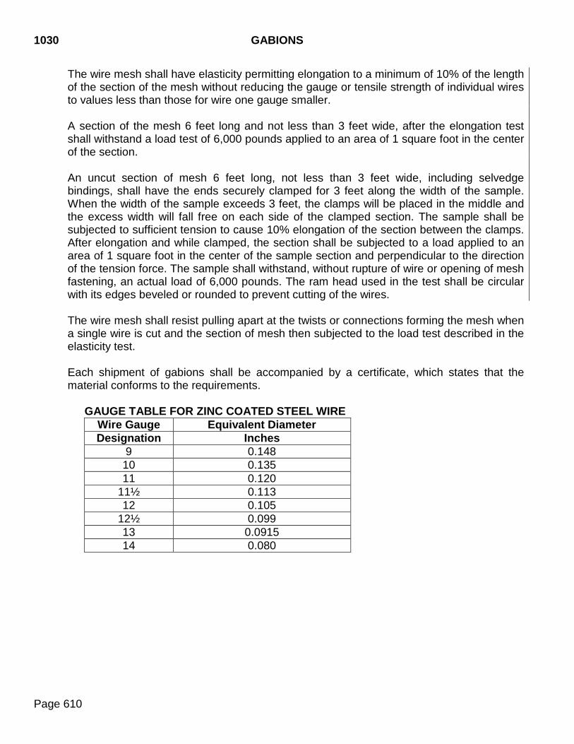
1030 GABIONS
Page 610
The wire mesh shall have elasticity permitting elongation to a minimum of 10% of the length of the section of the mesh without reducing the gauge or tensile strength of individual wires to values less than those for wire one gauge smaller.
A section of the mesh 6 feet long and not less than 3 feet wide, after the elongation test shall withstand a load test of 6,000 pounds applied to an area of 1 square foot in the center of the section.
An uncut section of mesh 6 feet long, not less than 3 feet wide, including selvedge bindings, shall have the ends securely clamped for 3 feet along the width of the sample. When the width of the sample exceeds 3 feet, the clamps will be placed in the middle and the excess width will fall free on each side of the clamped section. The sample shall be subjected to sufficient tension to cause 10% elongation of the section between the clamps. After elongation and while clamped, the section shall be subjected to a load applied to an area of 1 square foot in the center of the sample section and perpendicular to the direction of the tension force. The sample shall withstand, without rupture of wire or opening of mesh fastening, an actual load of 6,000 pounds. The ram head used in the test shall be circular with its edges beveled or rounded to prevent cutting of the wires.
The wire mesh shall resist pulling apart at the twists or connections forming the mesh when a single wire is cut and the section of mesh then subjected to the load test described in the elasticity test.
Each shipment of gabions shall be accompanied by a certificate, which states that the material conforms to the requirements.
GAUGE TABLE FOR ZINC COATED STEEL WIRE Wire Gauge Equivalent Diameter Designation Inches
9 0.148 10 0.135 11 0.120
11½ 0.113 12 0.105
12½ 0.099 13 0.0915 14 0.080

STEEL SHEET PILING 1040
Page 611
1040 STEEL SHEET PILING Steel sheet piling shall be of the style, dimensions, and mass specified. Steel sheet piling shall conform to the requirements of ASTM A 328; ASTM A709, Grade 50; ASTM A690, ASTM A857, or as specified. The piling shall be true, straight, and uniform in section. The side of each piece shall be furnished with an interlock that is continuous for the full length of the sheet.

1050 STEEL SHEETING
Page 612
1050.1 SCOPE This specification covers the fabrication of galvanized steel sheet products.
1050.2 REQUIREMENTS The galvanized steel used in fabricated metal products shall conform to ASTM A929. The sheeting shall be true, straight, and uniform in section. The sheeting shall be galvanized at a rate of 2 ounces per square foot total for both sides. The steel sheeting for fabricated lightweight sheet piling and other items in which interlock is specified shall consist of corrugated or flat steel sheets which, when properly driven or installed, will interlock with adjacent sheets for the full length of the sheet. The interlock shall be formed by bending the metal 180 degrees, leaving an opening to allow free slippage of adjoining sheets. The specified metal products shall be fabricated to the strength, shape, and dimensions shown in the plans and so as to avoid cracking or breaking the spelter coating on the galvanized sheets.
INDEX
Page 613
- A - Abbreviations ................................................................................................................................... 1 Acceptance Final Acceptance and Final Payment .................................................................................. 82 Of Field Work ...................................................................................................................... 38 Addendum ....................................................................................................................................... 3 Advertisement .................................................................................................................................. 3 Aggregate Crushed for Maintenance Stockpiles ................................................................................ 517 Asphalt Concrete .............................................................................................. 126, 143, 543 Asphalt Surface Treatment ....................................................................................... 185, 546 Polymer Chip Seal .................................................................................................... 359, 527 Granular Bases and Surfacing .................................................................................. 117, 547 Portland Cement Concrete ............................................................................... 193, 524, 530 Air-Entraining Admixtures ............................................................................................................ 519 American with Disabilities Act ........................................................................................................ 56 Asphalt Concrete ......................................................................................................................... 125 Additives ........................................................................................................................... 126 Aggregates ....................................................................................................... 126, 143, 543 Asphalt Binder................................................................................................................... 552 Composite ......................................................................................................................... 165 Batch Plant ....................................................................................................................... 128 Class D ............................................................................................................................. 141 Class E ............................................................................................................................. 141 Class G ............................................................................................................................. 141 Class HR ........................................................................................................................... 169 Class S ............................................................................................................................. 167 Cold Recycling of .............................................................................................................. 189 Compaction ............................................................................................................... 133, 153 Composition of .................................................................................................................. 125 Crack Sealing ................................................................................................................... 181 Drum Mix Plants................................................................................................................ 128 Equipment ......................................................................................................................... 126 Hydrated Lime................................................................................................................... 521 Maintenance ..................................................................................................................... 137 Mix Design Submittal ................................................................................................ 131, 145 Pavers ............................................................................................................................... 129 Proportioning of Aggregates ............................................................................................. 132 Rollers ............................................................................................................................... 130 Salvaging, Processing, and Stockpiling ............................................................................ 121 Shoulder Joint Sealant ...................................................................................................... 126 Stockpiling Aggregate ....................................................................................................... 130 Tacking, Spreading, and Compacting ............................................................................... 133 Transportation and Delivery of .......................................................................................... 133 Weather and Seasonal Limitations ................................................................................... 126 Asphalt Concrete Composite ....................................................................................................... 165 Asphalt Material ........................................................................................................................... 552
INDEX
Page 614
Asphalt Surface Treatment .......................................................................................................... 185 Aggregates for ................................................................................................................... 546
- B -
Backfilling Above Bedding Grade ............................................................................................... 276, 301 Bridge End ....................................................................................................................... 291 Select Granular ................................................................................................................. 537 Bank and Channel Protection ...................................................................................................... 489 Base Course .................................................................................................................... 3, 117, 547 Bid Proposal ............................................................................................................................... 3, 16 Combination Bidding Packages .......................................................................................... 19 Consideration of .................................................................................................................. 21 Contents of Bidding Package .............................................................................................. 13 Dismissal of ......................................................................................................................... 23 Guaranty ............................................................................................................................. 17 Interpretation of Quantities in Bidding Package .................................................................. 14 Irregular ............................................................................................................................... 22 Issuance of Bidding Package .............................................................................................. 13 Limitations, Bidder Submitted .............................................................................................. 18 Preparation of ...................................................................................................................... 16 Proposal Form ..................................................................................................................... 16 Public Opening of ................................................................................................................ 19 Return of Proposal Guaranty ............................................................................................... 24 Submission of ...................................................................................................................... 18 Withdrawal or Revision of .................................................................................................... 19 Bid Schedule .................................................................................................................................... 3 Bidder .............................................................................................................................................. 3 Cancellation of Award ......................................................................................................... 24 Disqualification of ................................................................................................................ 21 Prequalification of ................................................................................................................ 13 Requirement of Contract Performance Bond ...................................................................... 24 Blotting Sand ................................................................................................................................ 542 Bonded Fiber Matrix ..................................................................................................................... 501 Box Culverts Drainage Fabric ................................................................................................................. 283 Bridge .............................................................................................................................................. 3 Bridge Deck Preparation and Resurfacing ................................................................................... 375 Bridge End Backfill ....................................................................................................................... 291 Bridge Field Painting/Repainting .................................................................................................. 267 Bronze Castings ........................................................................................................................... 563 Buy America ................................................................................................................................... 46
- C -
Cable Guardrail ............................................................................................................................ 423 Calcium Chloride .......................................................................................................................... 523
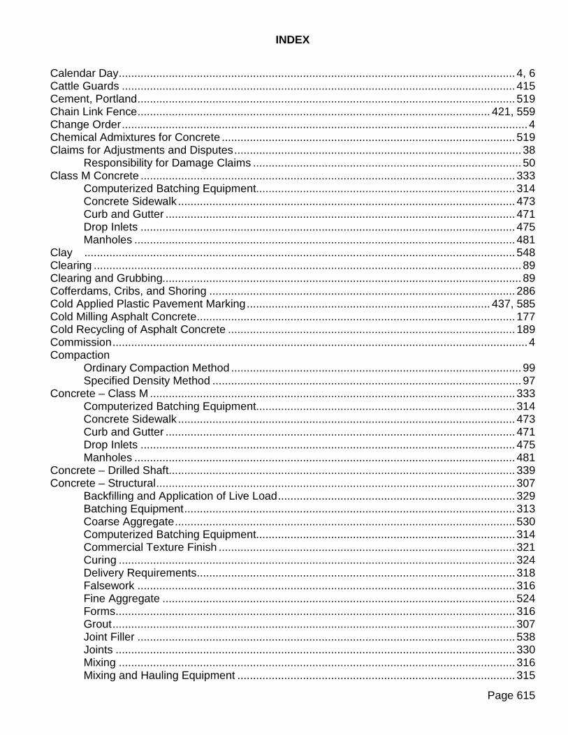
INDEX
Page 615
Calendar Day ............................................................................................................................... 4, 6 Cattle Guards .............................................................................................................................. 415 Cement, Portland ......................................................................................................................... 519 Chain Link Fence ................................................................................................................. 421, 559 Change Order .................................................................................................................................. 4 Chemical Admixtures for Concrete .............................................................................................. 519 Claims for Adjustments and Disputes ............................................................................................ 38 Responsibility for Damage Claims ...................................................................................... 50 Class M Concrete ........................................................................................................................ 333 Computerized Batching Equipment................................................................................... 314 Concrete Sidewalk ............................................................................................................ 473 Curb and Gutter ................................................................................................................ 471 Drop Inlets ........................................................................................................................ 475 Manholes .......................................................................................................................... 481 Clay .......................................................................................................................................... 548 Clearing ......................................................................................................................................... 89 Clearing and Grubbing................................................................................................................... 89 Cofferdams, Cribs, and Shoring .................................................................................................. 286 Cold Applied Plastic Pavement Marking .............................................................................. 437, 585 Cold Milling Asphalt Concrete ...................................................................................................... 177 Cold Recycling of Asphalt Concrete ............................................................................................ 189 Commission ..................................................................................................................................... 4 Compaction Ordinary Compaction Method ............................................................................................. 99 Specified Density Method ................................................................................................... 97 Concrete – Class M ..................................................................................................................... 333 Computerized Batching Equipment................................................................................... 314 Concrete Sidewalk ............................................................................................................ 473 Curb and Gutter ................................................................................................................ 471 Drop Inlets ........................................................................................................................ 475 Manholes .......................................................................................................................... 481 Concrete – Drilled Shaft............................................................................................................... 339 Concrete – Structural ................................................................................................................... 307 Backfilling and Application of Live Load ............................................................................ 329 Batching Equipment .......................................................................................................... 313 Coarse Aggregate ............................................................................................................. 530 Computerized Batching Equipment................................................................................... 314 Commercial Texture Finish ............................................................................................... 321 Curing ............................................................................................................................... 324 Delivery Requirements ...................................................................................................... 318 Falsework ......................................................................................................................... 316 Fine Aggregate ................................................................................................................. 524 Forms ................................................................................................................................ 316 Grout ................................................................................................................................. 307 Joint Filler ......................................................................................................................... 538 Joints ................................................................................................................................ 330 Mixing ............................................................................................................................... 316 Mixing and Hauling Equipment ......................................................................................... 315
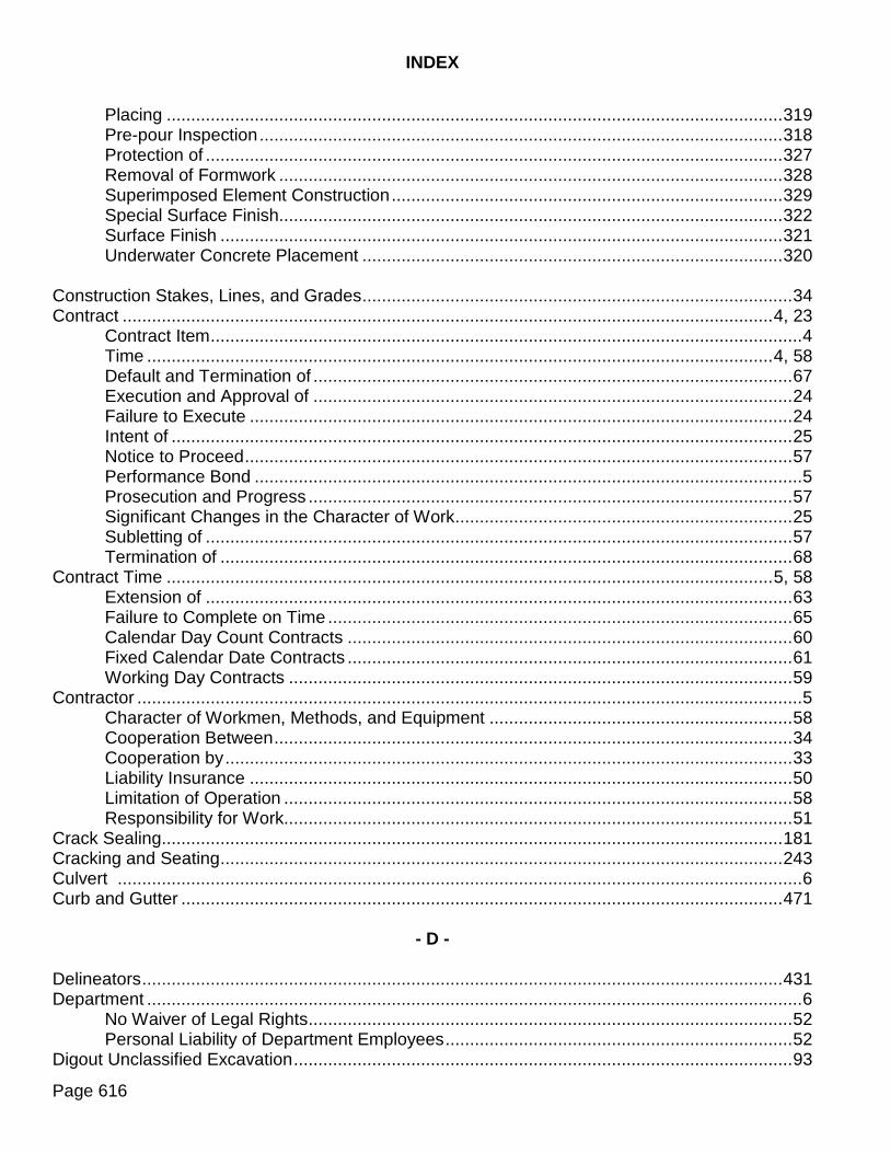
INDEX
Page 616
Placing .............................................................................................................................. 319 Pre-pour Inspection ........................................................................................................... 318 Protection of ...................................................................................................................... 327 Removal of Formwork ....................................................................................................... 328 Superimposed Element Construction ................................................................................ 329 Special Surface Finish ....................................................................................................... 322 Surface Finish ................................................................................................................... 321 Underwater Concrete Placement ...................................................................................... 320 Construction Stakes, Lines, and Grades ........................................................................................ 34 Contract ..................................................................................................................................... 4, 23 Contract Item ......................................................................................................................... 4 Time ................................................................................................................................ 4, 58 Default and Termination of .................................................................................................. 67 Execution and Approval of .................................................................................................. 24 Failure to Execute ............................................................................................................... 24 Intent of ............................................................................................................................... 25 Notice to Proceed ................................................................................................................ 57 Performance Bond ................................................................................................................ 5 Prosecution and Progress ................................................................................................... 57 Significant Changes in the Character of Work ..................................................................... 25 Subletting of ........................................................................................................................ 57 Termination of ..................................................................................................................... 68 Contract Time ............................................................................................................................ 5, 58 Extension of ........................................................................................................................ 63 Failure to Complete on Time ............................................................................................... 65 Calendar Day Count Contracts ........................................................................................... 60 Fixed Calendar Date Contracts ........................................................................................... 61 Working Day Contracts ....................................................................................................... 59 Contractor ........................................................................................................................................ 5 Character of Workmen, Methods, and Equipment .............................................................. 58 Cooperation Between .......................................................................................................... 34 Cooperation by .................................................................................................................... 33 Liability Insurance ............................................................................................................... 50 Limitation of Operation ........................................................................................................ 58 Responsibility for Work ........................................................................................................ 51 Crack Sealing ............................................................................................................................... 181 Cracking and Seating ................................................................................................................... 243 Culvert ............................................................................................................................................ 6 Curb and Gutter ........................................................................................................................... 471
- D -
Delineators ................................................................................................................................... 431 Department ...................................................................................................................................... 6 No Waiver of Legal Rights ................................................................................................... 52 Personal Liability of Department Employees ....................................................................... 52 Digout Unclassified Excavation ...................................................................................................... 93
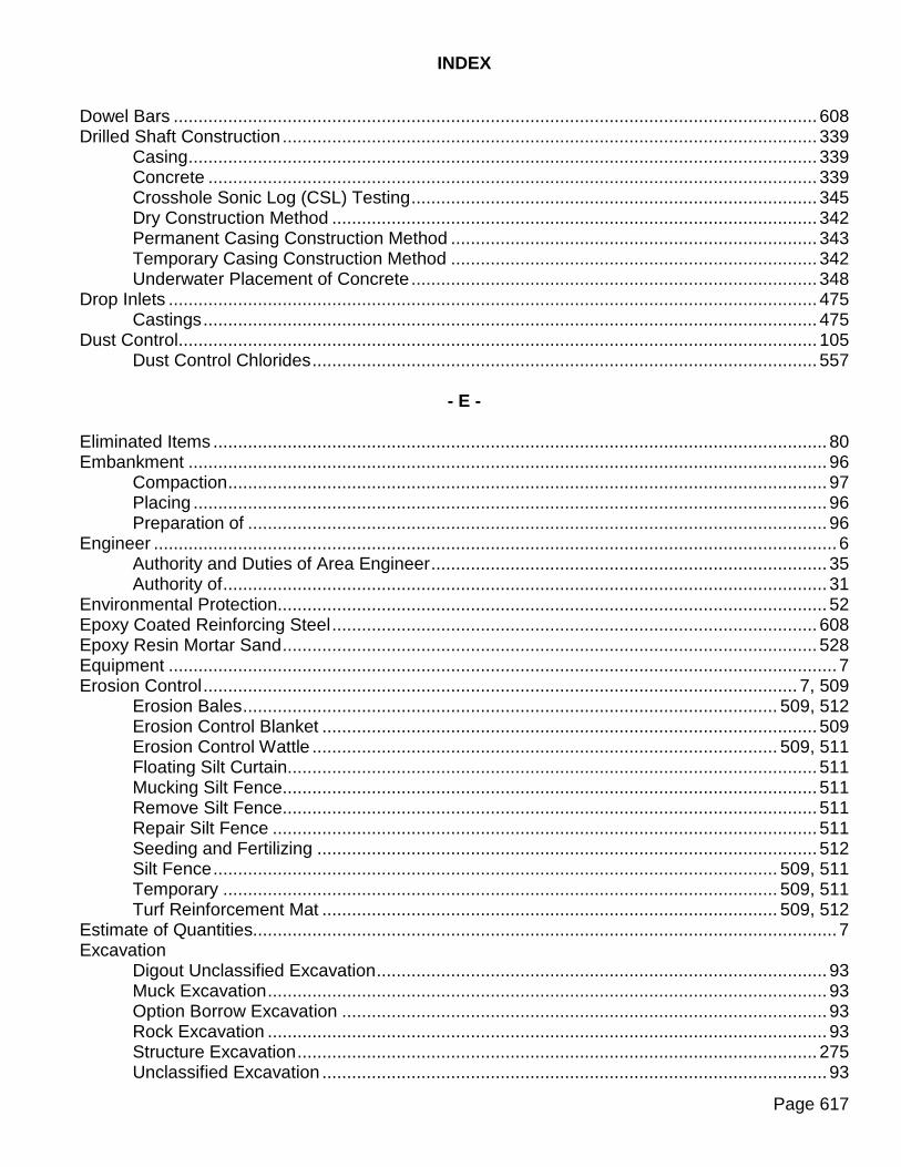
INDEX
Page 617
Dowel Bars .................................................................................................................................. 608 Drilled Shaft Construction ............................................................................................................ 339 Casing ............................................................................................................................... 339 Concrete ........................................................................................................................... 339 Crosshole Sonic Log (CSL) Testing .................................................................................. 345 Dry Construction Method .................................................................................................. 342 Permanent Casing Construction Method .......................................................................... 343 Temporary Casing Construction Method .......................................................................... 342 Underwater Placement of Concrete .................................................................................. 348 Drop Inlets ................................................................................................................................... 475 Castings ............................................................................................................................ 475 Dust Control ................................................................................................................................. 105 Dust Control Chlorides ...................................................................................................... 557
- E -
Eliminated Items ............................................................................................................................ 80 Embankment ................................................................................................................................. 96 Compaction ......................................................................................................................... 97 Placing ................................................................................................................................ 96 Preparation of ..................................................................................................................... 96 Engineer .......................................................................................................................................... 6 Authority and Duties of Area Engineer ................................................................................ 35 Authority of .......................................................................................................................... 31 Environmental Protection ............................................................................................................... 52 Epoxy Coated Reinforcing Steel .................................................................................................. 608 Epoxy Resin Mortar Sand ............................................................................................................ 528 Equipment ....................................................................................................................................... 7 Erosion Control ........................................................................................................................ 7, 509 Erosion Bales ............................................................................................................ 509, 512 Erosion Control Blanket .................................................................................................... 509 Erosion Control Wattle .............................................................................................. 509, 511 Floating Silt Curtain ........................................................................................................... 511 Mucking Silt Fence ............................................................................................................ 511 Remove Silt Fence ............................................................................................................ 511 Repair Silt Fence .............................................................................................................. 511 Seeding and Fertilizing ..................................................................................................... 512 Silt Fence .................................................................................................................. 509, 511 Temporary ................................................................................................................ 509, 511 Turf Reinforcement Mat ............................................................................................ 509, 512 Estimate of Quantities...................................................................................................................... 7 Excavation Digout Unclassified Excavation ........................................................................................... 93 Muck Excavation ................................................................................................................. 93 Option Borrow Excavation .................................................................................................. 93 Rock Excavation ................................................................................................................. 93 Structure Excavation ......................................................................................................... 275 Unclassified Excavation ...................................................................................................... 93
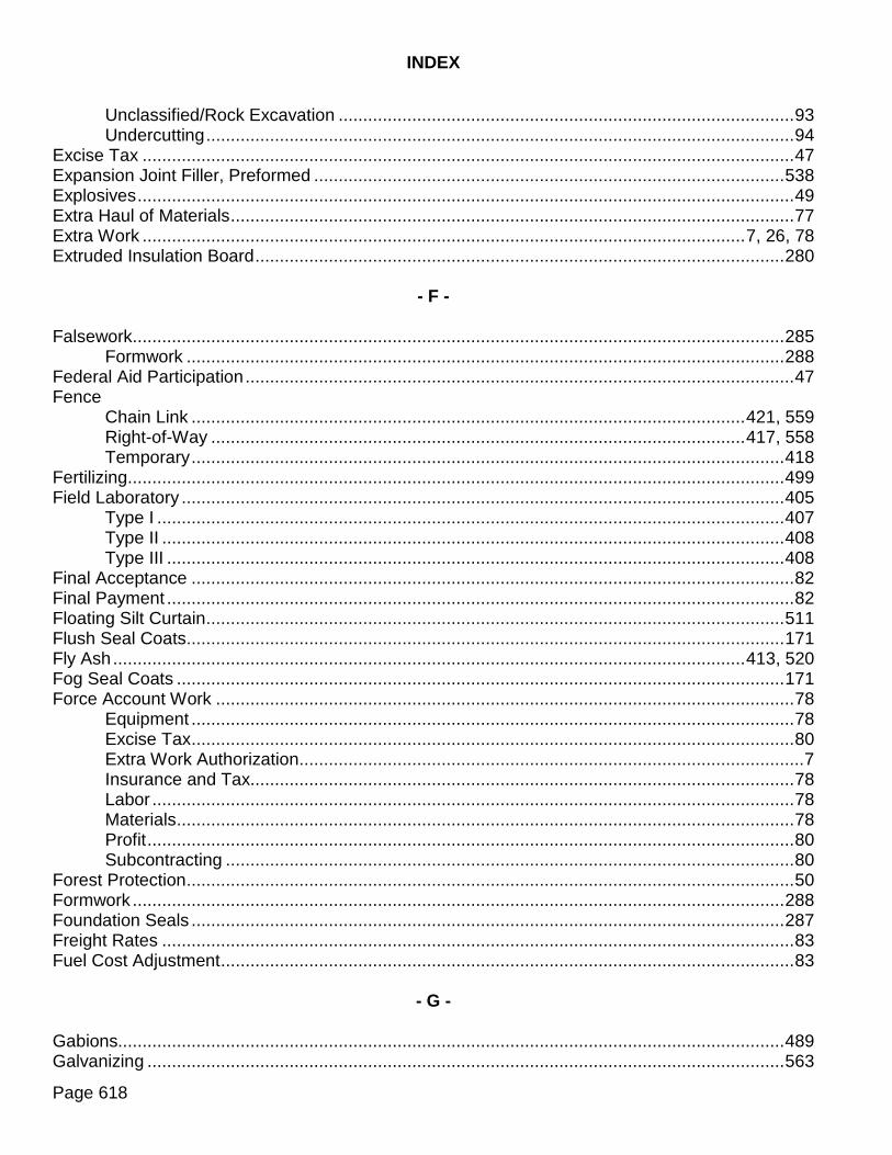
INDEX
Page 618
Unclassified/Rock Excavation ............................................................................................. 93 Undercutting ........................................................................................................................ 94 Excise Tax ..................................................................................................................................... 47 Expansion Joint Filler, Preformed ................................................................................................ 538 Explosives ...................................................................................................................................... 49 Extra Haul of Materials ................................................................................................................... 77 Extra Work ........................................................................................................................... 7, 26, 78 Extruded Insulation Board ............................................................................................................ 280
- F -
Falsework..................................................................................................................................... 285 Formwork .......................................................................................................................... 288 Federal Aid Participation ................................................................................................................ 47 Fence Chain Link ................................................................................................................. 421, 559 Right-of-Way ............................................................................................................. 417, 558 Temporary ......................................................................................................................... 418 Fertilizing...................................................................................................................................... 499 Field Laboratory ........................................................................................................................... 405 Type I ................................................................................................................................ 407 Type II ............................................................................................................................... 408 Type III .............................................................................................................................. 408 Final Acceptance ........................................................................................................................... 82 Final Payment ................................................................................................................................ 82 Floating Silt Curtain ...................................................................................................................... 511 Flush Seal Coats .......................................................................................................................... 171 Fly Ash ................................................................................................................................. 413, 520 Fog Seal Coats ............................................................................................................................ 171 Force Account Work ...................................................................................................................... 78 Equipment ........................................................................................................................... 78 Excise Tax ........................................................................................................................... 80 Extra Work Authorization ....................................................................................................... 7 Insurance and Tax............................................................................................................... 78 Labor ................................................................................................................................... 78 Materials .............................................................................................................................. 78 Profit .................................................................................................................................... 80 Subcontracting .................................................................................................................... 80 Forest Protection ............................................................................................................................ 50 Formwork ..................................................................................................................................... 288 Foundation Seals ......................................................................................................................... 287 Freight Rates ................................................................................................................................. 83 Fuel Cost Adjustment ..................................................................................................................... 83
- G -
Gabions........................................................................................................................................ 489 Galvanizing .................................................................................................................................. 563
INDEX
Page 619
Geotextile .................................................................................................................................... 536 Glass Beads ................................................................................................................................ 573 Granular Bases and Surfacing ..................................................................................................... 117 Salvaging, Processing, and Stockpiling ............................................................................ 121 Aggregates for .................................................................................................................. 547 Gravel Cushion and Gravel Cushion, Salvaged ................................................................ 119 Gravel Surfacing and Gravel Surfacing, Salvaged ............................................................ 120 Subbase and Base Course ............................................................................................... 119 Subbase, Salvaged and Base Course, Salvaged ............................................................. 119 Gravel Cushion ............................................................................................................................ 119 Gravel Surfacing .......................................................................................................................... 120 Guardrail Cable ................................................................................................................................ 423 Steel Beam ....................................................................................................................... 427
- H -
Haul Roads .................................................................................................................................. 411 Health and Safety Provisions ......................................................................................................... 48 Heavy Roadway Shaping ............................................................................................................ 107 Highway Signs and Delineators ................................................................................................... 431 Holiday............................................................................................................................................. 7 Hydrated Lime ............................................................................................................................. 521 Hydroseeding .............................................................................................................................. 497
- I -
Incidental Work ............................................................................................................................ 115 Inspection of Work ......................................................................................................................... 35 Inspector .......................................................................................................................................... 7 Duties of .............................................................................................................................. 35
- J -
Joint Sealer .................................................................................................................................. 539
- L -
Laboratory ........................................................................................................................... 143, 405 Field .................................................................................................................................. 405
Quality Assurance ............................................................................................................. 143 Quality Control .................................................................................................................. 143
Laws to be Observed ..................................................................................................................... 47 Liability Insurance .......................................................................................................................... 50
INDEX
Page 620
- M -
Maintenance During Construction............................................................................................................. 37 Failure to Maintain Roadway or Structure ........................................................................... 37 Of Traffic ............................................................................................................................. 26 Manholes ..................................................................................................................................... 481 Brick .......................................................................................................................... 481, 482 Cast in Place ............................................................................................................. 481, 482 Concrete Block .......................................................................................................... 481, 482 Precast Units ............................................................................................................. 481, 482 Masonry Mortar Sand .................................................................................................................. 528 Material Buy America ........................................................................................................................ 46 Department Furnished ......................................................................................................... 46 Handling .............................................................................................................................. 45 Local Material Sources ........................................................................................................ 41 Samples, Tests, Cited Specifications .................................................................................. 44 Source of Supply and Quality Requirements ....................................................................... 41 Storage of ............................................................................................................................ 45 Unacceptable ...................................................................................................................... 45 Mobilization .................................................................................................................................... 82 Muck Excavation ............................................................................................................................ 93 Mulching....................................................................................................................................... 501 Bonded Fiber Matrix .......................................................................................................... 501 Fiber Mulch ....................................................................................................................... 501 Fiber Reinforced Matrix ..................................................................................................... 501 Grass Hay or Straw Mulch ................................................................................................ 501
- N -
Navigable Waters Construction over or Adjacent to ......................................................................................... 48 Notice to Proceed .......................................................................................................................... 57
- O -
Obliterating Old Roads ................................................................................................................. 113 Opening Sections of Project to Traffic ............................................................................................ 51 Option Borrow Excavation.............................................................................................................. 93 Ordinary Roadway Shaping ......................................................................................................... 107
- P -
Painting Shop .................................................................................................................................. 263 Field .................................................................................................................................. 267 Paint Residue Containment ......................................................................................................... 270
INDEX
Page 621
Patented Devices, Materials, and Processes ................................................................................ 47 Pavement Jacking ....................................................................................................................... 237 Pavement Marking ....................................................................................................................... 437 Cold Applied Plastic .................................................................................................. 437, 585 Grooving for ...................................................................................................................... 439 Pavement Marking Paint and Beads ................................................................................. 438 Traffic Paint ....................................................................................................................... 569 Pavement Structure ......................................................................................................................... 8 Payment Final Acceptance and Final Payment .................................................................................. 82 For Extra Haul of Materials ................................................................................................. 77 For Materials Delivered to Project ....................................................................................... 81 Progress Payments ............................................................................................................. 80 Prompt Payment ................................................................................................................. 87 Scope of .............................................................................................................................. 77 Permits, Licenses, and Taxes ........................................................................................................ 47 Piling .......................................................................................................................................... 367 Bearing Value ................................................................................................................... 369 Cutting off Piles ................................................................................................................. 371 Driving ............................................................................................................................... 368 Preparation for .................................................................................................................. 367 Sheet Piling ............................................................................................................... 367, 613 Steel Sheeting .......................................................................................................... 367, 612 Test Piles .......................................................................................................................... 370 Timber Piles .............................................................................................................. 367, 561 Pipe Culverts ....................................................................................................................... 303, 606 Backfill above Bedding Grade ........................................................................................... 305 Bedding ............................................................................................................................. 304 Concrete ................................................................................................................... 303, 606 Corrugated Metal ...................................................................................................... 303, 606 Polyethylene ............................................................................................................. 304, 607 Plans .............................................................................................................................................. 8 Conformity with ................................................................................................................... 31 Coordination of.................................................................................................................... 32 Examination of .................................................................................................................... 14 Plans and Working Drawings .............................................................................................. 31 Plastic Pavement Marking, Cold Applied ............................................................................. 437, 585 Portland Cement Concrete Pavement ......................................................................................... 193 Air-Entraining Admixtures ................................................................................................. 519 Bar Reinforcement .................................................................................................... 355, 608 Batching Equipment .......................................................................................................... 194 Cement ............................................................................................................................. 519 Central Plant Mixing .......................................................................................................... 202 Chemical Admixtures ........................................................................................................ 519 Coarse Aggregate ............................................................................................................. 530 Concrete Saw ................................................................................................................... 198 Cracking and Seating ........................................................................................................ 243 Cure .......................................................................................................................... 212, 533
INDEX
Page 622
Delivery Requirements ...................................................................................................... 202 Dowel and Tie Bars ........................................................................................... 203, 355, 608 Edging ............................................................................................................................... 208 Fine Aggregate .................................................................................................................. 524 Finishing ............................................................................................................................ 205 Fly Ash ...................................................................................................................... 413, 520 Forms ................................................................................................................................ 200 Handling, Measuring, and Batching Materials ................................................................... 201 Incentive Payment ............................................................................................................. 217 Joint Sealer ....................................................................................................................... 539 Joints – Longitudinal.......................................................................................................... 210 Joints – Transverse ........................................................................................................... 211 Mixing ................................................................................................................................ 201 Mixing and Hauling Equipment .......................................................................................... 197 Opening to Traffic .............................................................................................................. 219 Pavement Jacking ............................................................................................................. 237 Placing .............................................................................................................................. 203 Preformed Expansion Joint Filler ...................................................................................... 538 Profilograph ....................................................................................................................... 214 Protection of ...................................................................................................................... 209 Quality of ........................................................................................................................... 193 Random Cracks ................................................................................................................ 211 Reinforcement and Dowel Bar Assemblies ....................................................... 203, 355, 608 Rubblize ............................................................................................................................ 245 Sealing Joints .................................................................................................................... 217 Slip Form Method .............................................................................................................. 201 Spall Repair ....................................................................................................................... 225 Spreading and Finishing Equipment ................................................................................. 197 Stationary Side Form Method ............................................................................................ 200 Surface Test ...................................................................................................................... 214 Ten Foot Straightedge ....................................................................................................... 214 Thickness .......................................................................................................................... 219 Truck Mixing ...................................................................................................................... 202 Undersealing ..................................................................................................................... 231 Vibrators ............................................................................................................................ 198 Water ................................................................................................................................. 523 Precast Concrete Box Culvert ...................................................................................................... 397 Precast/Prestressed Concrete ..................................................................................................... 393 Preformed Expansion Joint Filler ................................................................................................. 538 Preformed Fabric Pads ................................................................................................................ 563 Prestressed Concrete Beams ...................................................................................................... 399 Cure .................................................................................................................................. 402 Handling, Storage, Transportation, Installation ................................................................. 403 Pretensioning Reinforcement ............................................................................................ 399 Surface Finish and Patching ............................................................................................. 397 Prime, Tack, Fog Seal, and Flush Seal ........................................................................................ 171 Profile Grade .................................................................................................................................... 8 Prompt Payment ............................................................................................................................ 87
INDEX
Page 623
Public Convenience and Safety ..................................................................................................... 48
- Q -
Quantities Compensation for Altered ................................................................................................... 77 Measurement of .................................................................................................................. 71
- R -
Railing.......................................................................................................................................... 353 Railway-Highway Provisions .......................................................................................................... 48 Reinforcing Steel ................................................................................................................. 355, 608 Removal of Structures and Obstructions ....................................................................................... 91 Restoration Protection and Restoration of Property and Landscape ...................................................... 49 Of Surfaces Opened by Permit ........................................................................................... 47 Right-of-Way .................................................................................................................................... 9 Fence ................................................................................................................................ 417 Furnishing ........................................................................................................................... 52 Riprap .................................................................................................................................. 487, 535 Roadbed .......................................................................................................................................... 9 Roadside ......................................................................................................................................... 9 Roadway Shaping ....................................................................................................................... 107 Heavy ................................................................................................................................ 107 Ordinary ............................................................................................................................ 107 Surface Preparation .......................................................................................................... 107 Rock Excavation ............................................................................................................................ 93 Rubblize PCC Pavement ............................................................................................................. 245
- S -
Sand, Blotting .............................................................................................................................. 542 Seeding ....................................................................................................................................... 493 Hydroseeding .................................................................................................................... 497 Select Granular Backfill ............................................................................................................... 537 Select Subgrade Topping .............................................................................................................. 93 Sheet Piling ......................................................................................................................... 367, 611 Shop Painting .............................................................................................................................. 263 Shop Plans ....................................... 11, 31, 249, 353, 394, 476, 567, 575, 577, 590, 594, 595, 599 Shoulder ........................................................................................................................................ 10 Sidewalk ................................................................................................................................ 10, 473 Cushion Material ............................................................................................................... 473 Signs and Delineators.......................................................................................................... 431, 574 Concrete Footings ............................................................................................................. 432 Delineators ........................................................................................................................ 432 Fixed Base Assemblies ..................................................................................................... 432 Materials for ...................................................................................................................... 574
INDEX
Page 624
Object Markers .................................................................................................................. 432 Perforated Tube Posts .............................................................................................. 432, 575 Post Size ........................................................................................................................... 431 Signs ......................................................................................................................... 431, 574 Slip Base Assemblies ........................................................................................................ 432 Steel Posts ................................................................................................................ 432, 576 Wood Posts ............................................................................................................... 432, 576 Silt Fence ..................................................................................................................................... 509 Mucking ............................................................................................................................. 511 Repair of ............................................................................................................................ 511 Sodding ........................................................................................................................................ 505 Sodium Chloride .......................................................................................................................... 523 Sound Control Requirements ......................................................................................................... 56 Sources, Local Material ................................................................................................................. 41 Spall Repair ................................................................................................................................. 225 Epoxy Resin Mortar ........................................................................................................... 227 Type A Spalls .................................................................................................................... 227 Type B Spalls .................................................................................................................... 229 Special Provisions .......................................................................................................................... 10 Special Surface Finish ................................................................................................................. 314 Specifications ................................................................................................................................. 10 Special Provisions ............................................................................................................... 10 Standard Specifications ....................................................................................................... 10 Supplemental Specifications ............................................................................................... 10 State ............................................................................................................................................ 10 Steel Beam Guardrail ................................................................................................................... 427 Steel Sheeting ...................................................................................................................... 367, 612 Steel Structures ................................................................................................................... 249, 562 Assembling ........................................................................................................................ 251 Bearings and Anchorages ................................................................................................. 254 Bridge Painting/Repainting ................................................................................................ 267 Cambering ......................................................................................................................... 255 Falsework .................................................................................................................. 254, 285 High Strength Bolts ................................................................................................... 256, 564 Material ............................................................................................................................. 562 Preformed Fabric Pads ..................................................................................................... 563 Shop Painting ............................................................................................................ 254, 263 Shop Plans ........................................................................................................................ 249 Steel Forgings and Steel Shafting ..................................................................................... 562 Welded Stud Shear Connectors ........................................................................................ 562 Welder Qualification .......................................................................................................... 251 Welding Inspection ............................................................................................................ 250 Stockpiles....................................................................................................................................... 81 Aggregate for Maintenance Stockpiles .............................................................................. 517 Street ............................................................................................................................................ 10 Structural Plate Pipe and Structural Plate Pipe Arch Culverts ..................................................... 301 Backfill above Bedding Grade ........................................................................................... 301 Fabrication ........................................................................................................................ 301

INDEX
Page 625
Installation ......................................................................................................................... 301 Structure Excavation ................................................................................................................... 275 Box Culvert ....................................................................................................................... 277 Bridge ............................................................................................................................... 276 Cofferdams and Cribs ....................................................................................................... 275 Disposal of ........................................................................................................................ 275 Preservation of Channels .................................................................................................. 275 Structures ...................................................................................................................................... 10 Removal .............................................................................................................................. 91 Subbase ........................................................................................................................................ 10 Subcontractor ................................................................................................................................ 10 Subgrade ....................................................................................................................................... 10 Substructure .................................................................................................................................. 10 Superintendent .............................................................................................................................. 10 Superstructure ............................................................................................................................... 10 Supplemental Specifications .......................................................................................................... 10 Surety ............................................................................................................................................ 11 Surface Course .............................................................................................................................. 11 Surface Preparation ..................................................................................................................... 107
- T -
Tack Coats .................................................................................................................................. 171 Temporary Traffic Control .................................................................................................... 443, 587 Barricades and Warning Signs ........................................................................... 48, 443, 587 Flaggers ............................................................................................................................ 445 Maintenance of Traffic ........................................................................................................ 26 Removal of Pavement Markings ....................................................................................... 452 Temporary Pavement Marking .......................................................................................... 450 Temporary Works ........................................................................................................................ 285 Bridge Falsework .............................................................................................................. 285 Cofferdams, Cribs, and Shoring ........................................................................................ 286 Formwork .......................................................................................................................... 288 Foundation Seals .............................................................................................................. 287 Removal of ........................................................................................................................ 289 Tie Bars ....................................................................................................................................... 608 Topsoil ................................................................................................................................... 95, 111 Placing .............................................................................................................................. 111 Salvage ....................................................................................................................... 95, 111 Salvage of ........................................................................................................................... 95 Traffic Diversion ............................................................................................................................. 27 Traffic Paint ......................................................................................................................... 437, 569 Glass Beads ............................................................................................................. 437, 573 Traffic Signals and Roadway Lighting ................................................................................. 457, 590 Traveled Way ................................................................................................................................ 11 Tremie ......................................................................................................................................... 348
INDEX
Page 626
- U -
Unclassified Excavation ................................................................................................................. 93 Unclassified/Rock Excavation ........................................................................................................ 93 Undercutting ................................................................................................................................... 94 Undercutting – Culverts ............................................................................................................... 279 Backfill Material ................................................................................................................. 279 Bedding Material ............................................................................................................... 279 Extruded Insulation Board ................................................................................................. 279 Underdrains ................................................................................................................................. 485 Undersealing ................................................................................................................................ 231 Deflection Testing.............................................................................................................. 232 Utilities Cooperation With ................................................................................................................ 33
- V -
Value Engineering Incentive .......................................................................................................... 28
- W -
Waste Sites, Option ................................................................................................................. 41, 53 Water ............................................................................................................ 94, 100, 105, 120, 523 Water Pollution Control ................................................................................................................ 509 Wood Preservatives ..................................................................................................................... 560 Work ............................................................................................................................................ 11 Removal of Unacceptable and Unauthorized ...................................................................... 36 Working Drawings .......................................................................................................................... 11 Written Order ................................................................................................................................. 11 4500 copies of this document were printed by the South Dakota Department of Transportation at a cost of $4.17 per document.