tm 11-6625-524-14-2_voltmeter_an_urm-145_1974
TRANSCRIPT

8/10/2019 TM 11-6625-524-14-2_Voltmeter_AN_URM-145_1974
http://slidepdf.com/reader/full/tm-11-6625-524-14-2voltmeteranurm-1451974 1/53
TM 11-6625-524-14-2
TECHNICAL MANUAL
OPERATOR’S, ORGANIZATIONAL, DIRECT SUPPORT,
AND GENERAL SUPPORT MAINTENANCE MANUAL
INCLUDING REPAIR PARTS AND SPECIAL TOOLS LIST
(INCLUDING DEPOT MAINTENANCE REPAIR PARTS
AND SPECIAL TOOLS)
F O R
VOLTMETER, ELECTRONIC AN/URM-145B(NSN 6 6 2 5 -0 0 -4 3 7 -4 8 6 5 )
This copy is a reprint which includes current
pages from Changes 1. The title was
changed by Change 1,
H E A D Q U A R T E R S , D E P A R T M E N T O F T H E A R M
31 OCTOBER 197

8/10/2019 TM 11-6625-524-14-2_Voltmeter_AN_URM-145_1974
http://slidepdf.com/reader/full/tm-11-6625-524-14-2voltmeteranurm-1451974 2/53

8/10/2019 TM 11-6625-524-14-2_Voltmeter_AN_URM-145_1974
http://slidepdf.com/reader/full/tm-11-6625-524-14-2voltmeteranurm-1451974 3/53
TM 11-6625-524-1
T E C H N I C A L M A N U A L H E A D Q U A R T E R S
D E P A R T M E N T O F T H E A R M
No. 11-6625-524-14-2 W A S H I N G T O N , DC, 31 October 19
OPERATOR’S ORGANIZATIONAL, DIRECT SUPPORT, AND
GENERAL SUPPORT MAINTENANCE MANUAL
C HAPTER 1.
S ECTION I .
S ECTION I I .
C HAPTER 2.
C HAPTER 3.
C HAPTER 4.
C HAPTER 5.
VOLTMETER, ELECTRONIC AN/URM-145B
(NSN 6625-00-437-4865)
Par ag r aph
INTRODUCTION
General
Scope . . . . . . . . . . . . . . . . . . . . . . . . . . . . . . . . . . . . . . . . . . . . . . . . . . . . . . . . . . . . . . . . . . . . . . . . . . . . . . . . . . . 1-1
Indexes of publications . . . . . . . . . . . . . . . . . . . . . . . . . . . . . . . . . . . . . . . . . . . . . . . . . . . . . . . . . . . . . . . .. .1-2
Form s a nd r ecords . . . . . . . . . . . . . . . . . . . . . . . . . . . . . . . . . . . . . . . . . . . . . . . . . . . . . . . . . . . . . . . . . . . .. .1-3Administrative storage . . . . . . . . . . . . . . . . . . . . . . . . . . . . . . . . . . . . . . . . . . . . . . . . . . . . . . . . . . . . . . . . . . 1-3.1
Destruction of Army electronics materiel . . . . . . . . . . . . . . . . . . . . . . . . . . . . . . . . . . . . . . . . . . . . . . . . 1-3.2
Report ing of err ors . . . . . . . . . . . . . . . . . . . . . . . . . . . . . . . . . . . . . . . . . . . . . . . . . . . . . . . . . . . . . . . . . . . .. .1-4
Reporting Equipment Improvement Recommendations (EIR) . . . . . . . . . . . . . . . . . . . . . . . . . . . . . 1-4.1
Description and data
Description and use . . . . . . . . . . . . . . . . . . . . . . . . . . . . . . . . . . . . . . . . . . . . . . . . . . . . . . . . . . . . . . . . . . . . . 1-5
Technica l cha ra cteris tics . . . . . . . . . . . . . . . . . . . . . . . . . . . . . . . . . . . . . . . . . . . . . . . . . . . . . . . . . . . . . .. .1-6
Items comprising a n operable equipment . . . . . . . . . . . . . . . . . . . . . . . . . . . . . . . . . . . . . . . . . . . . . . ...1-7
INSTALLATION
Unpacking . . . . . . . . . . . . . . . . . . . . . . . . . . . . . . . . . . . . . . . . . . . . . . . . . . . . . . . . . . . . . . . . . . . . . . . . . . . . . . 2-1
Checking unpacked equipment . . . . . . . . . . . . . . . . . . . . . . . . . . . . . . . . . . . . . . . . . . . . . . . . . . . . . . . . . ..2-2
Cable connections . . . . . . . . . . . . . . . . . . . . . . . . . . . . . . . . . . . . . . . . . . . . . . . . . . . . . . . . . . . . . . . . . . . . . . . 2-3
OPERATING INSTRUCTIONS
General . . . . . . . . . . . . . . . . . . . . . . . . . . . . . . . . . . . . . . . . . . . . . . . . . . . . . . . . . . . . . . . . . . . . . . . . . . . . . . . . . 3-1
Preliminary operating instructions . . . . . . . . . . . . . . . . . . . . . . . . . . . . . . . . . . . . . . . . . . . . . . . . . . . . . . . 3-2
Contr ols and indicat ors . . . . . . . . . . . . . . . . . . . . . . . . . . . . . . . . . . . . . . . . . . . . . . . . . . . . . . . . . . . . . . . . ..3-3
Opera tin g procedures . . . . . . . . . . . . . . . . . . . . . . . . . . . . . . . . . . . . . . . . . . . . . . . . . . . . . . . . . . . . . . . . . . . . 3-4
OPERATOR’S AND ORGANIZATIONAL MAINTENANCE
Scope of maintenance . . . . . . . . . . . . . . . . . . . . . . . . . . . . . . . . . . . . . . . . . . . . . . . . . . . . . . . . . . . . . . . . . . . 4-1
Preventive maintenance . . . . . . . . . . . . . . . . . . . . . . . . . . . . . . . . . . . . . . . . . . . . . . . . . . . . . . . . . . . . . . . . . 4-2
P reventive maint enan ce checks a nd services periods . . . . . . . . . . . . . . . . . . . . . . . . . . . . . . . . . . . . ..4-3
Cleaning . . . . . . . . . . . . . . . . . . . . . . . . . . . . . . . . . . . . . . . . . . . . . . . . . . . . . . . . . . . . . . . . . . . . . . . . . . . . . ...4-4
Rustproofing and painting . . . . . . . . . . . . . . . . . . . . . . . . . . . . . . . . . . . . . . . . . . . . . . . . . . . . . . . . . . . . . . . 4-5
CIRCUIT FUNCTIONING
Block diagram . . . . . . . . . . . . . . . . . . . . . . . . . . . . . . . . . . . . . . . . . . . . . . . . . . . . . . . . . . . . . . . . . . . . . . . . . . 5-1
Rf probe . . . . . . . . . . . . . . . . . . . . . . . . . . . . . . . . . . . . . . . . . . . . . . . . . . . . . . . . . . . . . . . . . . . . . . . . . . . . . . . . 5-2
Range selector switch . . . . . . . . . . . . . . . . . . . . . . . . . . . . . . . . . . . . . . . . . . . . . . . . . . . . . . . . . . . . . . . . . . . 5-3
Input filter . . . . . . . . . . . . . . . . . . . . . . . . . . . . . . . . . . . . . . . . . . . . . . . . . . . . . . . . . . . . . . . . . . . . . . . . . . . . . . 5-4
Dc modulator . . . . . . . . . . . . . . . . . . . . . . . . . . . . . . . . . . . . . . . . . . . . . . . . . . . . . . . . . . . . . . . . . . . . . . . . . . . 5-5
Narrow band preamplifier . . . . . . . . . . . . . . . . . . . . . . . . . . . . . . . . . . . . . . . . . . . . . . . . . . . . . . . . . . . . .. .5-6
Driver and output circuit . . . . . . . . . . . . . . . . . . . . . . . . . . . . . . . . . . . . . . . . . . . . . . . . . . . . . . . . . . . . . . . . 5-7
Synchronous demodulator . . . . . . . . . . . . . . . . . . . . . . . . . . . . . . . . . . . . . . . . . . . . . . . . . . . . . . . . . . . . . . . 5-8
Driver . . . . . . . . . . . . . . . . . . . . . . . . . . . . . . . . . . . . . . . . . . . . . . . . . . . . . . . . . . . . . . . . . . . . . . . . . . . . . . . . . . 5-9
Reference amplifier . . . . . . . . . . . . . . . . . . . . . . . . . . . . . . . . . . . . . . . . . . . . . . . . . . . . . . . . . . . . . . . . . . . . . 5-10
Dc feedback and calibration controls . . . . . . . . . . . . . . . . . . . . . . . . . . . . . . . . . . . . . . . . . . . . . . . . . . . . . 5-11
Output, linearizing networks, and meter circuit . . . . . . . . . . . . . . . . . . . . . . . . . . . . . . . . . . . . . . . . . . 5-12
Regulated power supply . . . . . . . . . . . . . . . . . . . . . . . . . . . . . . . . . . . . . . . . . . . . . . . . . . . . . . . . . . . . . . . . . 5-13
P a g e
1-1
1-1
1-1
1-1
1-1
1-1
1-1
1-1
1-2
1-2
2-1
2-1
2-1
3-1
3-1
3-1
3-1
4-1
4-1
4-1
4-2
4-2
5-1
5-3
5-3
5-3
5-3
5-3
5-4
5-5
5-5
5-6
5-6
5-6
5-7
Change

8/10/2019 TM 11-6625-524-14-2_Voltmeter_AN_URM-145_1974
http://slidepdf.com/reader/full/tm-11-6625-524-14-2voltmeteranurm-1451974 4/53
TM 11-6625-524-14-2
C HAPTER 6.
S ECTION I .
I I .
I I I .
C H A P T E R 7 .
AP P E ND IX A.
B .
AP P E ND IX C .
S ECTION I . In troduct ion
I I .
I I I .
IV.
II . Ma intenance allocation chart
C -1
C -3
C -4
C -5Tool and test equipment requirements
R e m a r k s
Figure No.
1-1
1-2
1-3
2-1
3-13-2
5-1
5-2
5-3
5-4
5-5
5-6
5-7
5-8
5-9
5-10
6-1
6-2
6-3
6-47-1
7-2
7-3
TABLE OF CONTENTS - Continued
Paragraph P a g e
GENERAL SUPPORT MAINTENANCE INSTRUCTIONS
Troubleshooting
Troublesh ooting t echniqu es . . . . . . . . . . . . . . . . . . . . . . . . . . . . . . . . . . . . . . . . . . . . . . . . . . . . . . . . . . . ..6-1
Tools and Test Equipment
Tools an d Test equipment r equired for troubleshooting . . . . . . . . . . . . . . . . . . . . . . . . . . . . . . . ...6-2
Troublesh ooting cha rt . . . . . . . . . . . . . . . . . . . . . . . . . . . . . . . . . . . . . . . . . . . . . . . . . . . . . . . . . . . . . . . . . ..6-3
Signa l tr acing . . . . . . . . . . . . . . . . . . . . . . . . . . . . . . . . . . . . . . . . . . . . . . . . . . . . . . . . . . . . . . . 6-4
Dcresista nce of tra nsformers . . . . . . . . . . . . . . . . . . . . . . . . . . . . . . . . . . . . . . . . . . . . . . . . . . . . . . . . . . ..6-5
Maintenance
Alignment . . . . . . . . . . . . . . . . . . . . . . . . . . . . . . . . . . . . . . . . . . . . . . . . . . . . . . . . . . . . . . . . . . . . . . . . . . . ... 6-6
Remova l of pc boar d . . . . . . . . . . . . . . . . . . . . . . . . . . . . . . . . . . . . . . . . . . . . . . . . . . . . . . . . . . . . . . . . . . ..6-7
Replacement of pc board . . . . . . . . . . . . . . . . . . . . . . . . . . . . . . . . . . . . . . . . . . . . . . . . . . . . . . . . . . . . . ..6-8
GENERAL SUPPORT TESTING PROCEDURES
General testing procedures . . . . . . . . . . . . . . . . . . . . . . . . . . . 7-1
Test eq uipmen t r equir ed . . . . . . . . . . . . . . . . . . . . . . . . . . . . . . . . . . . . . . . . . . . . . . . . . . . . . . . . . . . . . . ..7-2
P ower supply t est . . . . . . . . . . . . . . . . . . . . . . . . . . . . . . . . . . . . . . . . . . . . . . . . . . . . . . . . . . . . . . . . . . . . ..7-3
Pr eamplifier and a mplifier test . . . . . . . . . . . . . . . . . . . . . . . . . . . . . . . . . . . . . . . . . . . . . . . . . . . . . . ...7-4
Volta ge accura cy test . . . . . . .. . . . . . . . . . . . . . . . . . . . . . . . . . . . . . . . . . . . . . . . . . . . . . . . . . . . . . . . . . . . . 7-5
REF ER ENC ES . . . . . . . . . . . . . . . . . . . . . . . . . . . . . . . . . . . . . . . . . . . . . . . . . . . . . . . . . . . . . . . . . . . . . .
ORGANIZATIONAL, DIRECT SUPPORT, AND GENERAL SUPPORT MAINTENANCE
REPAIR PARTS AND SPECIAL TOOLS LIST (INCLUDING DEPOT
MAINTENANCE REPAIR PARTS AND SPECIAL TOOLS) (Deleted)
MAINTENANCE ALLOCATION
6-1
6-3
6-3
6-3
6-4
6-4
6-4
6-5
7-1
7-1
7-1
7-2
7-2
A-1
LIST OF ILLUSTRATIONS
Title
Voltmet er, E lectronic AN/U RM-145B . . . . . . . . . . . . . . . . . . . . . . . . . . . . . . . . . . . . . . . . . . . . . . . . . . . . . . . . . . . . . .
Input capa citan ce of RF probe (meas ured a t 10 MHz) . . . . . . . . . . . . . . . . . . . . . . . . . . . . . . . . . . . . . . . . . . . . . .
In put resis ta nce of rf probe . . . . . . . . . . . . . . . . . . . . . . . . . . . . . . . . . . . . . . . . . . . . . . . . . . . . . . . . . . . . . . . . . . . . . . .
Typical pa ckaging dia gra m . . . . . . . . . . . . . . . . . . . . . . . . . . . . . . . . . . . . . . . . . . . . . . . . . . . . . . . . . . . . . . . . . . . . . . .
Fr ont pa nel contr ols . . . . . . . . . . . . . . . . . . . . . . . . . . . . . . . . . . . . . . . . . . . . . . . . . . . . . . . . . . . . . . . . . . . . . . . . . . . .Rear panel controls . . . . . . . . . . . . . . . . . . . . . . . . . . . . . . . .
Block diagram . . . . . . . . . . . . . . . . . . . . . . . . . . . . . . . . . . . . . . . . . . . . . . . . . . . . . . . .
Rf probe, simplified schemat ic diagra m . . . . . . . . . . . . . . . . . . . . . . . . . . . . . . . . . . . . . . . . . . . . . . . . . . . . . . . . . . . .
Na rrow ba nd prea mplifier, schema tic diagr am . . . . . . . . . . . . . . . . . . . . . . . . . . . . . . . . . . . . . . . . . . . . . . . . . . . . .
Driver a nd output, schemat ic diagra m . . . . . . . . . . . . . . . . . . . . . . . . . . . . . . . . . . . . . . . . . . . . . . . . . . . . . . . . . .
Synchronous demodulat or, simplified schematic diagr am . . . . . . . . . . . . . . . . . . . . . . . . . . . . . . . . . . . . . . . . .
Driver, simplified schemat ic diagr a m . . . . . . . . . . . . . . . . . . . . . . . . . . . . . . .
Reference am plifier, simplified schemat ic diagra m . . . . . . . . . . . . . . . . . . . . . . . . . . . . . . . . . . . . . . . . . . . . . . . . .
Scale correction netw ork, schema tic dia gra m . . . . . . . . . . . . . . . . . . . . . . . . . . . . . . . . . . . . . . . . . . . . . . . . . . . . .
Regulat ed power supply, simplified schema tic diagr am . . . . . . . . . . . . . . . . . . . . . . . . . . . . . . . . . . . . . . . . . . . . .
Voltm eter, E lectronic AN/UR M-145B , schema tic dia gra m . . . . . . . . . . . . . . . . . . . . . . . . . . . . . . . . . . . . . .
Voltage an d resistance measurements . . . . . . . . . . . . . . . . . . . . . . . . . . . . . . . . . . . .
Amplifier boa rd 3A2, locati on of par ts . . . . . . . . . . . . . . . . . . . . . . . . . . . . . . . . . . . . . . . . . . . . . . . . . . . . . . . . . . . . .
Ca libra tion boar d 3A3, loca tion of par ts . . . . . . . . . . . . . . . . . . . . . . . . . . . . . . . . . . . . . . . . . . . . . . . . . . . . . . . . . . .
Regula ted power s upply 3A1, locat ion part s . . . . . . . . . . . . . . . . . . . . . . . . . . . . . . . . . . . . . . . . . . . . . . . . . . . . . . .Power supply test setup . . . . . . . . . . . . . . . . . . . . . . . . . . . . . . . . . . . . . . . . . . . . . . . . . . . . . . . .
Preamplifier and amplifier test setup . . . . . . . . . . . . . . . . . . . . . . . . . . . . . . . . . . . . . . . . . . . . . . . . . .
Volta ge a ccura cy tes t s etu p... . . . . . . . . . . . . . . . . . . . . . . . . . . . . . . . . . . . . . . . . . . . . . . . . . . . . . . . . . . . . . . . . . . . .
P age
1-0
1-2
1-3
2-1
3-23-3
5-2
5-2
5-4
5-4
5-5
5-5
5-6
5-7
5-7
5-7
6-2
6-5
6-6
6-77-1
7-2
7-3
i Change 1

8/10/2019 TM 11-6625-524-14-2_Voltmeter_AN_URM-145_1974
http://slidepdf.com/reader/full/tm-11-6625-524-14-2voltmeteranurm-1451974 5/53

8/10/2019 TM 11-6625-524-14-2_Voltmeter_AN_URM-145_1974
http://slidepdf.com/reader/full/tm-11-6625-524-14-2voltmeteranurm-1451974 6/53
Figure 1 1.
TM 11-6625-524-14-2
-0 Change 1
8/10/2019 TM 11-6625-524-14-2_Voltmeter_AN_URM-145_1974
http://slidepdf.com/reader/full/tm-11-6625-524-14-2voltmeteranurm-1451974 7/53
TM 11-6625-524-14
CHAPTER 1
INTRODUCTION
1-1. Scope
Section 1.
T h i s m an u a l d e sc r i b e s V o l t m e t e r , E l e c t ron i c
AN/U RM -145B (fig. 1-1) and provides instructions
for operation and organizational, direct support ,
and general support (GS) maintenance. Instruc-
tions are provided for the operator and the organi-
zat ional maintenance personnel for instal lat ion ,
operation, preventive maintenance, and replace-
ment of parts avai lable at organizat ional mainte-
nance. Circuit functioning is included for general
support maintenance, together with instructions
appropriate to this category of maintenance for
troubleshooting, test ing, adjusting, aligning and
repai r ing the equ ipment and rep lac ing main te-
nance parts .
1-2. Indexes of Publications
a. DA Pam 310-4. Refer to the latest issue of DA
Pam 310-4 to determine whether there are new
edit ions, changes or addit ional publicat ions per-
tain ing to the equipment .
b. DA Pam 310-7. Refer to DA Pam 310-7 to de-
termine whether there are Modificat ion Work Or-
ders (MWO’S) pertaining to the equipment.
1-3. Forms and Records
a. Reports of M ain tenan ce and U nsati sfactory
Equ ipment . Maintenance forms, records, and re-
ports which are to be used by maintenance person-
nel at al l maintenance levels are l is ted in and pre-
scribed by TM 38-750.
b. Report of Packaging and H andl in g Deficien-
ties. Fil l out and forward DD Form 6 (Packaging
Improvement Report) as prescribed in AR 700-
5 8 /N A V S U P I N S T 4 0 3 0 . 2 9 /A F R 7 1 -1 3 /M C O
P4030.29A, and DSAR 4145.8.
G E N E R A L
c. Discrepancy in Shipment Report (DISRE
(SF 361) . F i l l ou t and forward Discrepancy
Shipment Report (DISREP) (SF 361) as prescrib
in AR 55-38/NAVS U P INS T 4610.33A/AFR 75-1
MCO P 4610.19B, a nd D SAR 4500.15.
1-3.1. Administrative Storage
Administrat ive storage of equipment issued to a
used by Army activit ies shall be in accordance wi
TM 740-90-1.
1-3 .2 . Dest ruct ion of Army Elect ronic
Materiel.
Destruction of Army electronics materiel to pr
vent enemy use shall be in accordance with T
750-244-2.
1-4. Reporting of Errors.
You can help improve this manual by calling at te
t ion to errors and by recommending improvemen
and stat ing your reasons for the recommendation
Your le t t e r or DA Form 2028 (Recommend
Changes to Publicat ions and Blank Forms) shou
be mailed direct to Commander, US Army Ele
t ron ics Command , ATTN: DRSEL-MA-Q, Fo
Monmout h, New J ersey 07703. A reply w ill be funished direct to you.
1-4.1. Reporting Equipment Improveme
Recommendations (EIR).
EIR’s will be prepared using DA Form 2407 (Mai
t e n a n c e R e q u e s t ) . I n s t r u c t i o n s f o r p r e p a r i n
EIR’s are provided in TM 38-750, The Army Mai
tenance Management Sys tem. EIR’s shou ld b
mailed direct to Commander, US Army Electroni
C o m m a n d , A T T N : D R S E L - M A - Q , F o r t M o
mouth, New J ersey 07703. A reply w ill be furnish
direct to you.
Section Il. DESCRIPTION AND DATA
1-5. Description and Usefor many associated tests . Such measurements i
clude the frequency response of both active a
a. Voltm eter , Elect roni c AN/U RM-145B (voltm e- passive networks; that is, amplifiers, and filte
ter) is a sensit ive instrument for the measurement voltage standing wave rat io (vswr) ant i re turn lo
of voltages of 300 microvolt (uv) to 3 volts span- on t ransmission l ines and at tendant systems;
ning a frequency range of 20 kilohertz (KHz) to 600 tenuat ion and insert ion loss of r f at tenuators ; a
megaher t z (MHz) . In add i t ion to conven ien t ly h igh f requency parameters o f t rans is tors . Wi
measuring voltage levels in a diversity of radiofre- true root mean square (rms) response below 0.
quency (rf) circuits, the instrument has applicat ion volt , wide hand noise can be measured, and by u
Change 1 1
8/10/2019 TM 11-6625-524-14-2_Voltmeter_AN_URM-145_1974
http://slidepdf.com/reader/full/tm-11-6625-524-14-2voltmeteranurm-1451974 8/53
Figure 1 2.
TM 11-6625-524-14-2
of su i t ab le nul l ne tworks , measurement o f the
harmonic distortion of rf waveforms can be per-
formed wi thout the a t tendant errors of average-
type meters. The voltmeter is also useful as an rf
n u l l d e t e c t o r f o r b r i d g e m e a s u r e m e n t s a n d
analogous techniques when a sensitivity in the
order of 200 uv will suffice.
b. Supplied with each instrument is a general
purpose rf probe, 50-ohm adapter and probe tip.The adapter is fi t ted with a type bnc coaxial con-
nector and provides a 50-ohm termination with a
low vsw r up to 600 MHz . The probe tip is u seful for
direct measurement to approximately 250 MHz.
However, a short wire should be substi tuted for
the ground lead when using above 100 MHz to
minimize the effects of ground lead inductance.
Above 250 MHz, the probe may be used directly
without the tip, but the connecting leads must be
extremely short to avoid resonant effects. Nor-
ma lly, the rf probe is used w ith t he 50-ohm ad a pter
in a coaxial system for accurate measurementsabove 100 MHz.
c. The rf probe with its full-wave crystal detect-
ing circuit produces a true rrns response without
turnover, or harmonic errors for all voltage levels
below 0.03 volt, gradually changing to peak-to-
peak reading (calibrated in rms) at approximately
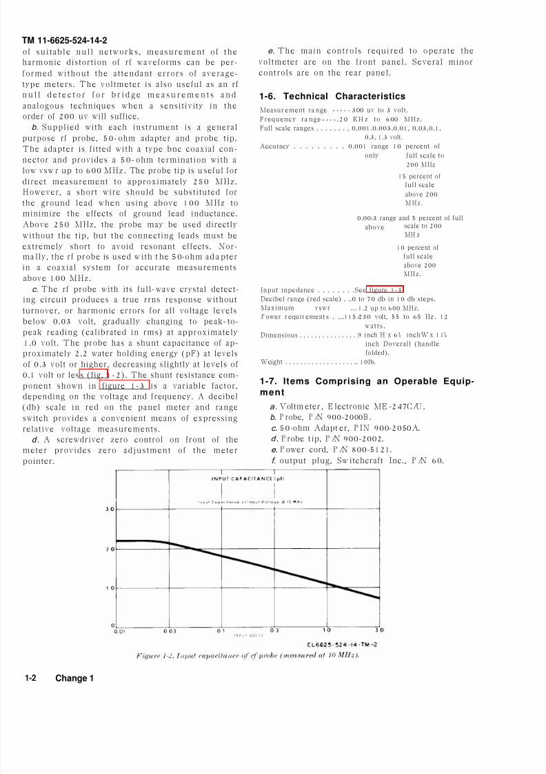
1.0 volt. The probe has a shunt capacitance of ap-
proximately 2.2 water holding energy (pF) at levels
of 0.3 volt or higher, decreasing slightly at levels of
0.1 volt or less (fig. 1-2). The shunt resistance com-
ponent shown in figure 1-3 is a variable factor,
depending on the voltage and frequency. A decibel
(db) scale in red on the panel meter and rangeswitch provides a convenient means of expressing
relative voltage measurements.
d. A screwdriver zero control on front of the
meter provides zero adjustment of the meter
pointer.
e. The main controls required to operate the
voltmeter are on the front panel. Several minor
controls are on the rear panel.
1-6. Technical Characteristics
Measur ement ra nge 300 uv to 3 volt.
Frequency ra nge .20 KH z to 600 MHz.
Full scale ranges . . . . . . . . 0.001.0.003.0.01, 0.03,0.1,
0.3, 1.3 volt.
Accuracy . . . . . . . . . 0.001 range 10 percent of
only full scale to
200 MHz
15 percent of
full scale
above 200
MHz.
0.00:3 range and 5 percent of full
above scale to 200
MH z
10 percent of
full scale
above 200
MHz.
Input inpedance . . . . . . . .See figure 1-3.
Decibel range (red scale) . ..0 to 70 db in 10 db steps.
Maximum vswr . . . 1.2 up to 600 MHz.
P ower r equir ement s . ...115/230 volt, 55 to 65 Hz . 12
wa t t s .
Dimensious . . . . . . . . . . . . . . . .9 inch H x 6½ inchW x 11¼
inch Doverall (handle
folded).
Weight . . . . . . . . . . . . . . . . . . .. 10lb.
1-7. Items Comprising an Operable Equip-
ment
a. Voltm eter , E lectronic ME -247C/U .b. P robe, P /N 900-2000B .
c. 50-ohm Adapt er, P IN 900-2050A.
d. P robe t ip, P /N 900-2002.
e. P ower cord, P /N 800-5121.
f. output plug, Sw itchcraft Inc., P /N 60.
1-2 Change 1

8/10/2019 TM 11-6625-524-14-2_Voltmeter_AN_URM-145_1974
http://slidepdf.com/reader/full/tm-11-6625-524-14-2voltmeteranurm-1451974 9/53
Figure 1 3.
TM 11-6625-524-14

8/10/2019 TM 11-6625-524-14-2_Voltmeter_AN_URM-145_1974
http://slidepdf.com/reader/full/tm-11-6625-524-14-2voltmeteranurm-1451974 10/53

8/10/2019 TM 11-6625-524-14-2_Voltmeter_AN_URM-145_1974
http://slidepdf.com/reader/full/tm-11-6625-524-14-2voltmeteranurm-1451974 11/53
TM 11-6625-524-14-
CHAPTER 2
I N S T A L L A T I O N
2-1. Unpackinga. Packaging Data. When packed for ship-
ment , Voltmet er, E lectron ic A-N/U RM - 145B is
placed in a waterproof carton and packed in a
corrugated cardboard box. A typical packing case
and its contents are shown in figure 2-1.
b . Remo v i n g Co n t e n t s . P e r f or m a l l t h e
procedures in (1) through (4) below when un-
packing equipment.
(1) Open the outer corrugated carton and
moistureproof barrier.
(2) Remove the inner carton.
(3) Open the inner corrugated carton.
(4) Remove the voltmeter.
2-2. Ch ecking Unpacked Equipment
a. Inspect the equipment for damage incurred
during shipment.
b. Check to see that the equipment is complet(paragraph 1-6). Report all discrepancies in ac
cordance with TM 38-750. Shortage of a mino
assembly or par t tha t does not a f fec t p rope
functioning of the equipment should not preven
use of the equipment.
c. If the equipment has been used or recon
dit ioned, see whether it has been changed by a
modif icat ion work order (MWO). I f the equip
ment has been modified, the MWO number wil
appear on the side near the nomenclature. Check
to see whether the MWO number (if any) and
ap p rop r i a t e n o t a t i on s c on c e rn i n g t h e m od i
f i c a t i on h av e b e e n e n t e re d i n t h e e qu i p m e nmanual .
NOTE
C u r r e n t M W O ’s a p p l ic a b l e t o t h e
equipment are listed in DA Pam 310-7.
Fi gure 2-1. Typical packaging diagram.
2-3. Cable Connections d. Screw the probe tip on the rf probe for direct
Connect the cables and adapters as follows: measurements up to 100 MHz. Above 100 MHz,
a. Insert the power cord plug into the three- the probe may be used without the t ip.
prong receptacle on the rear panel.
b. Insert the rf probe plug into the receptacleCAUTION
on the front panel.Above 250 MHz, connecting leads must
c. Screw the 50-ohm adapter on the rf probeb e e x t re m e l y sh or t t o av o i d re son an t
when a 50-ohm termination is required. effects.
2-1

8/10/2019 TM 11-6625-524-14-2_Voltmeter_AN_URM-145_1974
http://slidepdf.com/reader/full/tm-11-6625-524-14-2voltmeteranurm-1451974 12/53

8/10/2019 TM 11-6625-524-14-2_Voltmeter_AN_URM-145_1974
http://slidepdf.com/reader/full/tm-11-6625-524-14-2voltmeteranurm-1451974 13/53
TM 11-6625-524-14
CHAPTER 3
O P E R A T I N G I N S T R U C T I O N S
3-1. General 3-2. Preliminary Operating InstructionsThis section should be read carefully before using a. Set 115/230 volts sw itch, on t he rea r pa nethe voltmeter. I t contains information necessary for the input voltage to be used.for proper operation of the voltmeter. To achieve b. S e t L I N E sw i t c h a t O F F .v a l i d r e a d i n g s , proper s w i t c h s e t t i n g s a r e c. Turn the adjusting screw on the front panrequired. C o n t r o l s a n d i n d i c a t o r s , w i t h t h e meter until the pointer is at SET REF.funct ion of each, are l is ted in paragraph 3-3.
Operating procedures are described in paragraph
3-4. The controls are shown in figures 3-1 and 3-2.
3-3. Controls and Indicators
The controls for the voltmeter are on the front an
rear panels. Their functions are described in t ab
3-1.
Tabl e 3-1. Controls and Ind icators
Control or indicator
Range selector switch
SET REF control. . .
LINE switch . . . . . . . . . .
LINE lamp..
P R O B E c o n n e c t o r .
Mechanical zero adjust screw (rear panel controls).
DC OUTPUT jack . . . . . . . . . . . . . . . . . . . . . . . . . . .
P OWER connector . . . . . . . . . . .
115/230 VOLTS sw it ch
3-4. Operating Procedures
Function
a. Genera l . Be fore opera t ing the vol tmeter ,
check the meter to see if the pointer falls on the
SET REF mark. It it does not , turn the SET REF
control until the pointer is exactly over the SET
REF mark. At the low end of the 0.001 scale of
the meter, 100 uv and 200 uv points are provided.
These are designated by the small numerals 1 and
2 and should be used only on this r a nge.
CAUTIONDamage to the d iode car t r idge in the
probe may result if the input exceeds 500volts dc or 40 volts peak-to-peak.
b. M easur ement Pr ocedu r e.
(1) Set LINE switch to ON.
Selects one of eight voltage ranges.
Adjusts the meter pointer to the reference point with zero
input signal. Should perferably be adjusted on the lowest
range.
A two position ON-OFF switch. Connect AC power to the
voltmeter at the ON position.
Indicat es that ac power is applied when l i t .
A nine pin receptacle which accepts the rf probe connector.
Provided for mechanical zero adjustment of the meter pointer.
A tip, ring, sleeve phone-type jack for dc output.
A three pin receptacle which accepts the power cord connector.
Selects tr an sformer connections for 115 or 230 volts input.
(2) Connect the probe tip to the probe fo
direct measurement or the 50-ohm adapter fo
measurements in 50-ohm systems or above 10
MHz. Above 250 MHz, the probe may be use
directly without the adapter.
( 3 ) I f t h e a p p r o x i m a t e v o l t a g e t o b
measured is known, set the range selector switc
to the appropriate scale. Otherwise, set switch a
3 volts scale and turn switch to lower scales unt
a proper meter reading is obtained.
(4) To obtain readings in db, add db mete
reading (red scale on meter) to the db setting the range selector switch.
3

8/10/2019 TM 11-6625-524-14-2_Voltmeter_AN_URM-145_1974
http://slidepdf.com/reader/full/tm-11-6625-524-14-2voltmeteranurm-1451974 14/53
Figure 3 1.
TM 11-6625-524-14-2
3-2

8/10/2019 TM 11-6625-524-14-2_Voltmeter_AN_URM-145_1974
http://slidepdf.com/reader/full/tm-11-6625-524-14-2voltmeteranurm-1451974 15/53
TM 11-6625-524-14
Fi gu r e 3 -2. Rea r pan el con t r o l s.
WARNING measur ing low level r f vo l t ages , a lways t a
Do not exceed 5W r f when using any of the precautions to avoid the possibility of erroneo
adapters wi th the probe. readings resulting from hum, noise, or stray
c. H um , N oise, and Spur ious Pickup. W h e n pickup. Al though al l low frequency hum a

8/10/2019 TM 11-6625-524-14-2_Voltmeter_AN_URM-145_1974
http://slidepdf.com/reader/full/tm-11-6625-524-14-2voltmeteranurm-1451974 16/53
TM 11-6625-524-14-2
noise is attenuated at the input by 60 db, i t is sti l l
possible for high level unwanted signals to get
through and cause errors. The best test for this
condition is to reduce the test signal to zero level
and note whether the voltmeter continues to read
some spurious signal level. In some cases, extra
shie ld ing may be necessary a round the probe
connections to reduce stray field pickup. Typicalsources of spurious radiat ion are induct ion or
die lec t r i c hea t ing uni t s , d i a thermy machines ,
loca l r adio t r ansmi t ters , gr id d ip meters , and
amplifiers with parasitic oscil lations.
d. M agneti c Field s. Operation of the voltmeter
in strong 60 Hertz (Hz) magnetic fields, such as
t h o s e-
su rr ou nd in g u n s h ie ld e d p ow e r t r ans-formers, should be avoided. The magnetic field
induces small 60 Hz currents in the amplifier
section of the instrument which, due to the ex-tremely high gain at this frequency, appear as an
indication on the meter.
3 - 4

8/10/2019 TM 11-6625-524-14-2_Voltmeter_AN_URM-145_1974
http://slidepdf.com/reader/full/tm-11-6625-524-14-2voltmeteranurm-1451974 17/53
TM 11-6625-524-1
CHAPTER 4
O P E R A T O R ’ S A N D O R G A N I Z A T I O N A L M A I N T E N A N C E
4-1. Scope of Maintenancea. Th e m a i n t e n a n c e du t i e s a s s i g n e d t o t h e
operator of the voltmeter are l isted below together
with a reference to the paragraphs covering the
specific m a i n t e n a n c e f u n c t i o n s . T h e d u t i e s
assigned do not require tools or test equipment
other than those issued with the equipment.
(1) Cleaning (para 4-4).
(2) Rustproofing and paint ing.
b. Th e m a i n t e n a n c e du t i e s a s s i g n e d t o t h e
o r g a n i z a t i o n a l m a i n t e n a n c e r e p a i r m a n o f t h e
v o l t m e t e r a r e s h o w n i n table 4-1. The dut ies
assigned do not require tools or test equipment
other than those issued with the equipment.
4-2. P r event ive Maintenance
Prevent ive maintenance i s the sys temat i c care ,
s e r v i c i n g , a n d i n s p e c t i o n o f t h e e q u i p m e n t t o
prevent the occurrence o f t roub le , to reduce
downt ime, and to assure tha t the equipment i s
serviceable. The procedures given in table 4-1
c o v e r r o u t i n e s y s t e m a t i c c a r e a n d c l e a n i n g
essential to proper upkeep and operation of the
equipment .
4-3. Preventive Maintenance Checks and Ser-
vices PeriodsPrevent ive maintenance checks and services of
t he AN/U RM -145B/U a rer e q u i r e d d a i lweekly, monthly, and quarterly as shown in tab
4-1 and under the special conditions listed belo
a. Before the voltmeter is taken on a missio
b. When the vol tmeter is ini t ia l ly insta l le
c. Wh e n t h e v o l t m e t e r i s r e i n s t a l l e d a f t
removal for any reason.
d. At least once a week, if the equipment
mainta ined in s t andby condi t ion . Per form th
m a i n t e n a n c e f u n c t i on s i n d i ca t e d i n t h
organiza t iona l monthly prevent ive maintenan
checks and services table once each month.
month is defined as approximately 30 calend
days of 8-hour-per-day operat ion. I f the equiment i s opera ted 16 hours a day , the month
p r e v e n t i v e m a i n t e n a n c e c h e c k s a n d s e r v i c
s h o u l d b e p e r fo r m e d a t 1 5 -da y i n t e r v a l s . A
jus tment o f the maintenance in terva l mus t b
made to compensa te for any unusua l opera t in
condi t ions . Equipment mainta ined in a s t and
(ready for immediate operat ion) condi t ion mu
have monthly preventive maintenance checks a
services. Equipment in limited storage (requir
service before operation) does not require month
maintenance.
8/10/2019 TM 11-6625-524-14-2_Voltmeter_AN_URM-145_1974
http://slidepdf.com/reader/full/tm-11-6625-524-14-2voltmeteranurm-1451974 18/53
TM 11-6625-524-14-2
W-weekly Q-Quarterly
I tem
Number A
1
2
3
4
5
6
7
8
9
10
11
12
13
14
15
16
17
18
19
lnterva l
Operator
B
x
x
x
x
Dai l y
D
x
x
x
W
x
x
x
Or g.
M
x
x
Q
x
x
x
x
x
x
x—
Ta ble 4-1. Pr event iv e M ai nt enan ce Ch ecks and Servi ces
B - Before Operation A-After Operation M-Monthly
D-During Operation
Item to be Inspected
Voltmeter . . . . . . . . . . .
Exterior surfaces . . . .
E x t e rna l recep t a c l es
Meter glass . . . . . . . . .
Knobs, controls, and
switches
Operation . . . . . . . .
Voltmeter . . . . . . . . . . .
Ca bles . . . . . . . . . . . . . .
Ha rdwa re . . . . . . . . . . .
Preservation . . . . . . .
P ublications . . . . . . . . .
MWO’s . . . . . . . . . . . . . .
Completeness . . . . . . .
Exterior surfaces . . . .
External receptacles.
Preservation . . . . . . . .
M et er g la s s . . . . . . . .
Ca bles . . . . . . . . . . . . . .
Operation . . . . . . . . . . .
Procedure
Check for completeness a nd general
condition.Check exterior surfaces.
Inspect external receptacles for breakage
and looseness.
Inspect gla ss w indow for brea ks, physical
dama ge, dust , or moisture.
During operation, check knobs, controls,
and switches for proper mechanical a ct ion.
Be alert for any abnormal indicat ions.
Check for any peculiar odors which would
indicate overheated components.
Inspect cables for cuts, cracked or gouged
jackets, fra ying, or kinks.
Inspect al l exterior h ar dwa re for looseness
and damage.
Inspect equipment for bare spots, rust a ndcorrosion.
Inspect manua l for completeness an d usa ble
condit ion. B e sure tha t a l l chan ges are on
hand.
Check to see that al l U RG ENT MWO’S
have been applied and that al l NORMAL
MWO’S ha ve been scheduled.
Sa me as i tem 1.
Sa me as i tem 2.
Sa me as i tem 3.
Sa me as i tem 10.
Sa me as i tem 4.
Sa me as i tem 8.
Sa me as i tem 6.
Reference
(Pa ra 4-7).
(Para 4-7 and4-8).
DA Pam 310-4
DA Pam 310-7
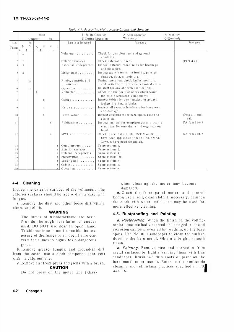
4-4. Cleaning when c lean ing ; the meter may become
Inspect the exterior surfaces of the voltmeter. The
exterior sur faces should be free of dirt , grease, a nd
fungus.
a. Remove the dust and other loose dirt with a
clean, soft cloth.
WARNING
The fumes of trichloroethane are toxic.
Provide thorough ven t i l a t ion whenever
used. DO NOT use near an open flame.
Trichloroethane is not flammable, but ex-
posure of the fumes t o an open flam e con-
verts the fumes to highly toxic dangerous
gases.
b. Remove grease, fungus, and ground-in dirt
from the cases; use a cloth dampened (not wet)
with trichloroethane.
c. Remove dirt from plugs and jacks with a brush.
CAUTIONDo not press on the meter face (glass)
damaged .
d. Clean the f ron t pane l meter , and con t ro l
knobs; use a soft , clean cloth. If n ecessary , da mpen
the cloth with water; mild soap may be used for
more effective cleaning.
4-5. Rustproofing and Painting
a. Rustpr oofi ng. When the finish on the voltme-
ter ha s become badly scarred or dama ged, rust a nd
corrosion ca n be prevented by t ouching up t he ba re
spots. Use No. 000 sandpaper to clean the surface
down to the bare metal . Obtain a bright , smooth
finish.
b. Painti ng. Remove rust and corrosion from
metal surfaces by l ight ly sanding them with f ine
sandpaper. Brush two th in coats of paint on the
bare metal to protect it . Refer to the applicable
cleaning and refinishing practices specified in TB
43-0118.
4-2 Change 1
8/10/2019 TM 11-6625-524-14-2_Voltmeter_AN_URM-145_1974
http://slidepdf.com/reader/full/tm-11-6625-524-14-2voltmeteranurm-1451974 19/53
TM 11-6625-524-1
C H A P T E R 5
C I R C U I T F U N C T I O N I N G
5-1. Block DiagramThe basic circuitry of the voltmeter is best un-
derstood by reference to the block diagram (fig. 5-
1).
a. The input signal is sampled and detected by
the rf probe. The direct current (dc) output signal
f rom the probe , a f t e r pass ing th rough the a t -
tenuator section of the range selector switch, goes
through an input filter which rejects power line
f re qu e n c y c om p on e n t s w h i c h m i g h t c au se a
measuring error.
b. A single-pole, double-throw dc modulator
(3G1) then converts the dc signal into a nearly
symmetrical square wave.
c. The square wave is impedance matched and
ampl i f ied by a h igh impedance , narrow band
preamplif ier (3A2Q9 through Q12). I t s narrow
b an d w i d t h a l so i m p rov e s t h e s i g n a l - t o- n o i se—ra t io .
d. The preamplifier output is further amplified
in the driver and output stage (3A2Q13 and
3A2Q14).
e. The alternating current (ac) signal from to u t p u t s t a g e i s r e c t i f i e d b y a s y n c h r o n od e m o d u l a t o r ( 3 A 2 Q 7 a n d 3 A 2 Q 8 ) a n d t
resu l t an t dc ou tpu t i s used to provide hea
o v e r a l l d c f e e d b a c k a n d t e m p e r a t u r e co
pensation. The dc output is also linearized in t
output circuit and connected to the indicat i
meter.
f . The dc modulator output is also connected
a driver (3A2Q1 and 3A2Q2) which drives
reference amplifier (3A2Q3 and 3A2Q4).
g. The output from the reference amplifier
fed to the synchronous demodulator. The pharelat ionship between the reference amplifier a
the input signal determines the polarity of the
ou t p u t w h i c h i s c on n e c t e d t o t h e i n d i c a t i
meter.
h. An electronical ly regulated power supp
(3A1CR1 and 3A1CR2) plus transistors delive
-14.5 volts to the amplifier. The amplif
divides the power supply voltage to - 6 volts a
+ 8.5 volts .

8/10/2019 TM 11-6625-524-14-2_Voltmeter_AN_URM-145_1974
http://slidepdf.com/reader/full/tm-11-6625-524-14-2voltmeteranurm-1451974 20/53
Figure 5 1.
TM 11-6625-524-14-2
Fi gur e 5-2. R f p robe, sim p l i f i ed schemat i c d i a g ra m.
5-2

8/10/2019 TM 11-6625-524-14-2_Voltmeter_AN_URM-145_1974
http://slidepdf.com/reader/full/tm-11-6625-524-14-2voltmeteranurm-1451974 21/53
TM 11-6625-524-1
5-2. Rf Probe
The rf probe (fig. 5-2) contains a diode cartridge
assembly. The cartridge assembly contains acoupling capacitor, two matched diodes, a pair of
filter capacitors and a pellet resistor. The sealed
section of the rf probe housing contains two filter
resistors connected in series with the outputterminals of the diode cartridge, and a tern-
perature sensing thermistor network connected in
the dc feedback loop of the amplifier. The ther-
mistors are connected to the individual ranges bymeans of sections C and E of the range selector
switch 3S2. The individual pins of connector 3J1
are bypassed to ground by filter capacitors and
thus prevent any possible error introduced by
stray rf pickup in the probe cable.
5-3. Range Selector Switch
a. The range selector switch consists of sec-
tions A through H. Sections A and B (range
attenuator) contain resistive dividers supplying
the full or partial voltage to the input of theamplifier. This voltage, when modulated, am-
plified, and demodulated, will indicate on themeter a reading corresponding to the value of theinput signal within the accuracy rating of the
range being used.
b. Section D disconnects 3R55 to provideadditional gain on the two 10 west ranges.
c. Sections C and E, in conjunction withsection H, form part of the dc feedback loop.
Section H contains individual resistors and
potentiometers to control the main feedback loopof each midrange control. The thermistors,located in the rf probe, sense and correct for any
thermal errors occurring as a result of the tem-
perature characteristics of the rf diodes and switched into the circuit through sections C a
E.
d. Sections F and G switch in both resist
and potentiometers for correcting the nonlinea
of the rf diodes.
5-4. Input FilterThe input filter consists of RC networks and
tuned parallel T-network providing an effective
filter with a minimum of 60-db rejection
powerline. frequency.
5-5. Dc Modulator
A 94-Hz printed circuit plug-in dc modula
(3G1), is employed. It modulates the dc in
signal, and the resultant ac component is pedance matched to the narrow band prea
plifier.
5-6. Narrow Band Preamplifier
The narrow band preamplifier features a l
noise, high impedance input achieved by the
of a high quality field effect transistor 13A2QDiodes 3A2CR3 and 3A2CR4 form a clamp cir
to protect the input transistor from excess
overload. A three-stage conventional RC-coupcommon-emitter amplifier, consisting of 3A2QQ11, and Q12, with the input transistor 3A2
develop a gain of approximately 80 db. A tuparallel T-network in a negative feedback lofrom the collector of 3A2Q12 to the base
3A2Q10 narrows the amplifier bandwidth athus improves the signal-to-noise ratio. Tsupply voltage is held at +8.5 volts by Ze
diode 3A2VR1.

8/10/2019 TM 11-6625-524-14-2_Voltmeter_AN_URM-145_1974
http://slidepdf.com/reader/full/tm-11-6625-524-14-2voltmeteranurm-1451974 22/53
TM 11-6625-524-14-2
Fi gure 5-3. Nar row band preampli f ier , schematic di agram.
5-7. Driver and Output Circuit of signal applied to the base of the driver. Am-
The driver (3A2Q13) and output stage (3A2Q14) plifier gain control 3A2R55 is disconnected on the
a r e c o n v e n t i o n a l c a p a c i t o r - c o u p l e d s t a g e s . two lowest ranges to allow additional gain. The
Amplifier gain control 3A2R53 adjusts the level signal developed in the output stage is applied to
the synchronous demodulator.
Fi gure 5-4. D ri ver and output, schemati c diagram.

8/10/2019 TM 11-6625-524-14-2_Voltmeter_AN_URM-145_1974
http://slidepdf.com/reader/full/tm-11-6625-524-14-2voltmeteranurm-1451974 23/53
TM 11-6625-524-14
5-8. Synchronous Demodulator s ignal polar i t y . In th is operat ion the collect
Transistors 3A2Q7 and 3A2Q8 are utilized in this current is a function of collector voltage only, an
phase-sensitive rectifying circuit. The signal from is essentially independent from other transist
the output stage (3A2Q14) is compared with the parameters. The voltage applied to the base of t
reference signal from 3A2Q5 and 3A2Q6. The t r a n s i s t o r a c t s o n ly a s a p h ase - se n s i t i v
resultant dc output signal from this demodulator reference.
has a polarity corresponding to the original input
Fi gure 5-5. Synchronous demodul ator, sim pli f ied schemat ic diagr am.
5-9. Dr iver adjusted by 3A2R11. The frequency is factorThe driver, 3A2Q1 and 3A2Q2, is a two-transistor adjusted to 94 Hz.multivibrator circuit, the frequency of which is
Fi gur e 5-6. Dr iver, s impl i f i ed schemat i c d iagram.
5-

8/10/2019 TM 11-6625-524-14-2_Voltmeter_AN_URM-145_1974
http://slidepdf.com/reader/full/tm-11-6625-524-14-2voltmeteranurm-1451974 24/53
TM 11-6625-524-14-2
5-10. Reference Amplifier fo l lowers 3A2Q3 and 3A2Q4. The ampl i f ie rs
3A2Q5 and 3A2Q6 amplify this square wave, and
The 94-Hz squa re w a ve from the m odula tor dr iver it is coupled to the synchronous demodulator via
is sampled by the amplifier stages via emitter 3A2T1 .
Fi gure 5-7. Reference ampl if i er, sim pli f ied schemat ic di agram .
5-11. Dc Feedback and Calibration Controls of 3A2T2 and filter capacitor 3A1C6. For low
A port ion of the dc output voltage from the
synchronous demodulator is fed back to the dc
modulator to provide the excellent gain stability
of the voltmeter. This feedback rat io is deter-
mined by values of a resistor and potentiometer
connected in series and switched through section
H of range selector switch 3S2. One of the three
thermistors mounted in the rf probe is switched in
series with the previous combination by means of
sections C and E of 3S2. The dc feedback con-
trols, marked mid on the calibrat ion plate, are
used for accurate calibrat ion of the midscale for
each range. The appropriate feedback rat ion is
selected when switched to the desired range.
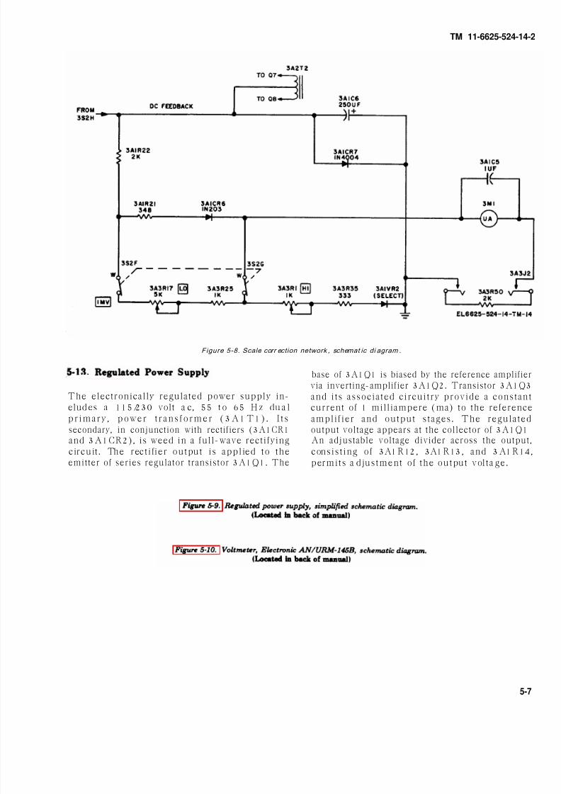
5-12. Output, Linearizing Networks, and Meter
CircuitThe dc output of the diodes in the probe is
basically nonlinear with respect to the rf input
l e v e l . I n o r d e r t o a c h i e v e a l i n e a r o u t p u t
characteristic, correction networks are employed.
Their function is to expand the lower end and
compress the upper end of the meter scale. Refer
t o figure 5-8 for be t t e r unders t and ing of the
circuit. The switch is at the 0.001 volt scale.
a. The rectified dc, proportional to the dc input
signal, appears at the center tap of the secondary
input levels, 50 percent of full scale and lower, the
s i g n a l p a s s e s t h r o u g h 3 A 3 R 2 2 , 3 A 3 R 2 1 ,
3A3CR6, 3M1, and 3A3R5. At low levels, the
re s i s t an c e o f 3 A 3 C R 6 i s f a i r l y h i g h an d t h ec u r r e n t t h r o u g h t h e c i r c u i t i s l i m i t e d . B y
paral le l ing 3A3R21 and 3A3CR6 with 3A3R17
and 3A3R25, an exact adjustment of the meter to
a point corresponding with the input voltage is
possible. For higher levels, 70 percent through
100 percent of full scale, 3A3R1, 3A3R35, and
3A3VR2 paralleled with 3M1 and 3A3R5 provide
adjustment of the meter to correspond with the
incoming signal. To adjust the midscale point,
the main dc feedback resistors are utilized.
b. Indicating meter 3M1 employes a taut band
movement t ha t is ra ted a t 0-500 microampere (ua)
d c . I t a l so u t i l i z e s a m i r ro r - b ac k e d sc a l e t o
minimize parallax errors.
c. Resis tor 3A3R5, in se r ies wi th 3M1, i s
connected to the circuit via 3J 2. For externa l
monitoring purposes, when a plug is inserted in
3J 2, 3A3R5 is sw itched out of the circuit a nd t he
external monitor must provide the 2K ohms series
load. This value should be within 1 percent to
maintain the rated cal ibrat ion accuracy of the
voltmeter.
5-6
8/10/2019 TM 11-6625-524-14-2_Voltmeter_AN_URM-145_1974
http://slidepdf.com/reader/full/tm-11-6625-524-14-2voltmeteranurm-1451974 25/53
Figure 5 10.
Figure 5 9.
5 13.
TM 11-6625-524-14
Figure 5-8. Scale corr ection network , schemat ic di agram .
base of 3A1Q1 is biased by the reference amplifie
via inverting-amplifier 3A1Q2. Transistor 3A1QThe electronically regulated power supply in- and its associated circuitry provide a constanelud es a 115/230 volt a c, 55 t o 65 H z du a l current of 1 milliampere (ma) to the referenc
pr imary , power t r ans former (3A1T1) . I t s amplifier and output stages. The regulatesecondary, in conjunction with rectifiers (3A1CR1 output voltage appears at the collector of 3A1Q1and 3A1CR2), is weed in a full-wave rectifying An adjustable voltage divider across the outpucircuit . The rect ifier output is applied to the consist ing of 3A1R12, 3A1R13, and 3A1R1emitter of series regulator transistor 3A1Q1. The permits a djustment of the output volta ge.
5

8/10/2019 TM 11-6625-524-14-2_Voltmeter_AN_URM-145_1974
http://slidepdf.com/reader/full/tm-11-6625-524-14-2voltmeteranurm-1451974 26/53

8/10/2019 TM 11-6625-524-14-2_Voltmeter_AN_URM-145_1974
http://slidepdf.com/reader/full/tm-11-6625-524-14-2voltmeteranurm-1451974 27/53
TM 11-6625-524-14
CHAPTER 6
G E N E R A L S U P P O R T M A I N T E N A N C E I N S T R U C T I O N S
Section I. TROUBLESHOOTING
6-1. Troubleshooting Techniques.
a. General . The first procedure in servicing a
defective voltmeter is to sectionalize the fault.
Sectionalization consists of tracing the fault to a
printed circuit b o a r d o r c h a s s i s . O n c e t h e
d e f e c t i v e b o a r d i s l o c a t e d , i s o l a t i o n t o t h e
defective part is accomplished. Troubleshooting
ia performed by the general support repairman.
b. Sect i onal i zat ion. Listed in (1) through (4)
below is a group of tests arranged to help locatethe defect.
(1) Visual inspection. When the voltmeter is
brought in for repair, remove the top cover and
inspect as follows:
(a) Check to see that all confections and pc
boards are properly seated. Repair or replace any
connections or leads that are broken or otherwise
defective.
(b) Check al l swi tches and controls fo
ease of operation.
(c) Inspect for loose or missing screw
(2) Operat iona l tests . O p e r a t i o n a l t e sfrequency indicate the general location of troubl
In many instances , the test will determine th
exact n a t u r e of t h e f a u l t . The opera t inprocedures (para 3-4), prevent ive maintenanc
checks (p a r a 4 -4 t o 4 -6 ) , a n d t h e a l i g n m e n
procedure (para 6-6) provide a good operationtest .
(3) Vol tage and resistance measurement
V o l t a g e a n d r e s i s t a n c e m e a s u r e m e n t a r
shown in figure 6-1. Several waveforms at cri t ic
poin ts a re shown in figure 5-10. Use these
localize trouble to a component.
6

8/10/2019 TM 11-6625-524-14-2_Voltmeter_AN_URM-145_1974
http://slidepdf.com/reader/full/tm-11-6625-524-14-2voltmeteranurm-1451974 28/53
TM 11-6625-524-14-2
Figure 6-1. Vo lt age and resist ance measurements.
(4) D C r es i s t a n c e o f t r a n s f o rm er s . D c dicat ions , o r l a c k o f m e t e r i n d i c a t i o n s a n dresistance of transformers are shown in paragraph operational checks provide a systematic method
6-6. of local izing trouble to the faul ty c i rcui t . The
(5) Tools and test equi pment . Tools and test trouble symptoms listed in the troubleshooting
equipment required for troubleshooting are shown chart (para 6-3) provide a dditional informa tion for
in section II. localizing troubles.
(6) Troub leshoo t i ng char t . The meter in-
6-2

8/10/2019 TM 11-6625-524-14-2_Voltmeter_AN_URM-145_1974
http://slidepdf.com/reader/full/tm-11-6625-524-14-2voltmeteranurm-1451974 29/53
TM 11-6625-524-14
Section II. TOOLS AND TEST EQUIPMENT
6-2. Tools and Test Equipment Required forTroubleshooting
a. Tools. No special tools are required.
Test equipment
E lectr onic Volt met er ME -30(*)/U
Oscilloscope AN/U SM -281
AC Meter, Millivac Model MV-45A
Signa l G enerat or AN/GR M-50
NOTE. (*) indicates all models.
6-3. Troubelshooting Chart
The fol lowing chart i s suppl ied as an a id in
locating trouble in the voltmeter. This chart lists
the symptoms observed during normal operation
Step Symptom
1
2
3
LINE lamp does not l ight when line
switch is turned to ON.
F u s e 3 A 3 F 1 b l o w s w h e n L I N E
switch is turned to ON,
LINE lamp l ights , vol tmeter does
not indicate on all ranges.
4 . Meter indicat ions abnormal on
r an g e s .
a ll
5 . Meter normal on all ranges but one.
6 Meter indication unstable or erratic.
6-4. Signal Tracing
b . T e s t E q u i p m e n t . T h e t e s t e q u i p m e
r e q u i r e d f o r t r o u b l es h o o t i n g i s l i s t e d b e l o w :
Technical manual Common name
TM 11-5511 Vtvm
TM 11-6625-1703-15 Scope
Ac meter
TM 11-6625-573-15 Signal Generator
t o l oc a l i ze th e t r ou b l e to a p c b oar d o r c omp on e
( I n c h a r t b e l ow , V & R s t a n d s f o r v o l t a g e a
r e s i s t a n c e .) U s e t h e p a r t s l o ca t i on i l l u s t r a t i o
( f i g s . 6- 2 t o 6 - 4 ) a n d s c h e m a t i c d i a g r a m (f i g . 5-
d u r i n g t r o u b l e s h o o t i n g .
Probable trouble
a. Fuse 3A3F1 is burned out.
b. LINE lamp 3DS1 defec t ive .
c. Defective power cord.
d. Line switch 3S1 defective.
e. 1 1 5 /2 3 0 v o l t s w i t c h 3 A 3 S 1
defective.
f. Transformer 3A1T1 defective.
Short circuit on power supply board.
a . Defec t on power supply board.
b, Defec t ive range se lec tor swi tch
3S2.
c. Defective met er 3 M 1
a. Defective modulator 3G1.
b. Defective amplifier board 3A2.
a. Check resistor on switch 3S2 for
defective range.
b. Check calibration resistors on 3A3board for defective range.
a. Defective cartridge in R F probe.
b. Power supply 3A1 defective.
c. Amplifier 3A2 defective.
Correction
a. Replace fuse. If new fuse blow
check steps 2 a nd 3 below.
b. Replace lamp.
c. C h e c k p o w e r c o r d ; r e p a i r o
replace.
d. C h e c k s w i t c h a n d r e p l a c e ,
necessary.
e. C h e c k s w i t c h a n d r e p l a c e ,
necessary.
f. Check transformer and replace,
necessary.Make V & R c h e c k s an d r e p l ac
faul ty par t .
a. Make V & R checks and repla
faul ty par t .
b. Check switch at defective range
Repair or replace.
c. Repair or r eplace.
a. Listen for a 94Hz hum. Replace
no hum.
b. Make V & R checks, Use sign
t r a c i n g ( p a r a 6 -4 ) . R e p l a
defective part.
a. Replace defective resistor.
b. Repla ce defective resistor.
a. R e m o v e a n d c h e c k c a r t r i d g
Replace if necessar y.
b. Repeat step 3 above.
c. Repeat step 4 above.
a n d p r e a m p l i f i e r c i r c u i t s . E x c e s s i v e
NOTE pickup will prevent making correct gain
When operat ing the vol tmeter removed and waveshape measurements. If pickup
f r o m t h e c a b i n e t , b e c a r e fu l t o a v o i d i s a p r ob le m , s h ie ld t h e v ol t m et e r b y
powerline hum pickup in the dc modulator placing aluminum plates at the bottom.
6
8/10/2019 TM 11-6625-524-14-2_Voltmeter_AN_URM-145_1974
http://slidepdf.com/reader/full/tm-11-6625-524-14-2voltmeteranurm-1451974 30/53
TM 11-6625-524-14-2
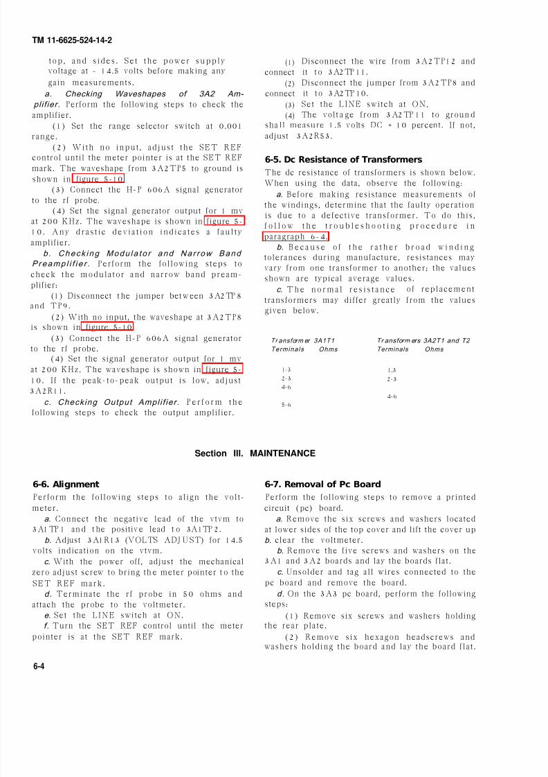
t op , an d s i d e s . S e t t h e p ow e r su p p l yvoltage at - 14.5 volts before making any
gain measurements.
a. Checking Waveshapes of 3A2 Am-
pl i f ier. Perform the following steps to check the
amplifier.
(1) Set the range selector switch at 0.001
range.(2) With no inpu t , ad jus t the SET REF
control until the meter pointer is at the SET REF
mark. The waveshape from 3A2TP5 to ground is
shown in figure 5-10.
(3) Connect the H-P 606A signal generator
to the rf probe.
(4) Set the signal generator output for 1 mv
at 200 KHz. The waveshape is shown in figure 5-
1 0 . A n y d ras t i c d e v i a t i on i n d i c a t e s a f au l t y
amplifier.
b . Check i ng Modu la to r and Na r row Band
Preamp l i f i e r . Perform the fol lowing steps to
check the modula tor and narrow band pream-plifier:
(1) Dis connect t he jumper bet w een 3A2TP 8and TP9.
(2) With no input, the waveshape at 3A2TP8is shown in figure 5-10.
(3) Connect the H-P 606A signal generator
to the rf probe.(4) Set the signal generator output for 1 mv
at 200 KHz. The waveshape is shown in figure 5-
10. I f the peak-to-peak output is low, adjust
3A2R11.
c. Checking Output Ampl i f ie r . P e r f o r m t h e
following steps to check the output amplifier.
(1)
connect
(2)connect
(3)
(4)
Disconnect the wire from 3A2TP12 and
it t o 3A2TP 11.
Disconnect the jumper from 3A2TP8 and
it t o 3A2TP 10.
Set the LINE switch at ON,
The volt a ge from 3A2TP 11 to groun d
sha ll measure 1.5 volts DC ± 10 percent . I f not ,
adjust 3A2R53.
6-5. Dc Resistance of Transformers
The dc resistance of transformers is shown below.
When using the data, observe the following:
a. Before making resistance measurements of
the windings, determine that the faulty operation
is due to a defect ive t ransformer. To do th is ,
f o l l o w t h e t r o u b l e s h o o t i n g p r o c e d u r e i n
paragraph 6-4.
b. B e c a u s e o f t h e r a t h e r b r o a d w i n d i n g
tolerances during manufacture, resistances may
vary from one transformer to another; the valuesshown are typical average values.
c. T h e n o r m a l r e s i s t a n c e of rep lacement
transformers may differ greatly from the values
given below.
Tr ansform er 3A1T1 Tr ansform ers 3A2T1 and T2
Termina ls Ohms Terminals Ohms
1-3 1.3
2-3 2-34-6
4-6
5-6
Section Ill. MAINTENANCE
6-6. Alignment
Perform the fol lowing steps to al ign the volt-
meter.
a. Connect the negative lead of the vtvm to
3A1TP 1 an d t he positiv e lead t o 3A1TP 2.
b. Adjust 3A1R13 (VOLTS ADJ U ST) for 14.5
volts indication on the vtvm.
c. With the power off, adjust the mechanical
zero adjust screw to bring th e meter pointer t o the
SET REF mark .
d. Terminate the rf probe in 50 ohms and
attach the probe to the voltmeter.
e. Set the LINE switch at ON.
f . Turn the SET REF control until the meter
pointer is at the SET REF mark.
6-7. Removal of Pc Board
Perform the following steps to remove a printed
circuit (pc) board.
a. Remove the six screws and washers located
at lower sides of the top cover and lift the cover up
b. clear the voltmeter.
b. Remove the five screws and washers on the
3A1 and 3A2 boards and lay the boards flat .
c. Unsolder and tag all wires connected to the
pc board and remove the board.
d. On the 3A3 pc board, perform the following
steps:
(1) Remove six screws and washers holdingthe rear plate .
(2) Remove six hexagon headscrews andwashers holding the board and lay the board f lat .
6-4

8/10/2019 TM 11-6625-524-14-2_Voltmeter_AN_URM-145_1974
http://slidepdf.com/reader/full/tm-11-6625-524-14-2voltmeteranurm-1451974 31/53
TM 11-6625-524-14
c. To replace the 3A3 board , per form t
following steps:
(1) Resolder all wires to the pc board a
components.
(2) Fasten the pc board to the chassis wi
six hexagon headscrews and washers removed
paragraph 6-7 d (2).
(3) Fasten the rear plate to the pc board wthe six screws and washers that were remov
(3) Unsolder and tag all wires connected to
the pc board and components and remove the
board .
6-8. Replacement of Pc Board
Perform the following steps to replace a pc board:
a. Resolder all wires to the 3A1 and 3A2 pc
boards .b. Fasten the pc board to the chassis with five
screws and washers removed in paragraph 6-7 b. (para 6- 7d (1).
Fi gure 6-2. Ampl if ier board 3A 2, location of part s.
6

8/10/2019 TM 11-6625-524-14-2_Voltmeter_AN_URM-145_1974
http://slidepdf.com/reader/full/tm-11-6625-524-14-2voltmeteranurm-1451974 32/53
Figure 6 3.
TM 11-6625-524-14-2
6 - 6

8/10/2019 TM 11-6625-524-14-2_Voltmeter_AN_URM-145_1974
http://slidepdf.com/reader/full/tm-11-6625-524-14-2voltmeteranurm-1451974 33/53
Figure 6 4.
TM 11-6625-524-14-2

8/10/2019 TM 11-6625-524-14-2_Voltmeter_AN_URM-145_1974
http://slidepdf.com/reader/full/tm-11-6625-524-14-2voltmeteranurm-1451974 34/53

8/10/2019 TM 11-6625-524-14-2_Voltmeter_AN_URM-145_1974
http://slidepdf.com/reader/full/tm-11-6625-524-14-2voltmeteranurm-1451974 35/53
Figure 7 1.
TM 11-6625-524-14
CHAPTER 7
G E N E R A L S U P P O R T T E S T I N G P R O C E D U R E S
7-1. G eneral Testing Procedures Ta ble 7-1. Test E quipm ent a. T estin g Pr ocedu res. The testing procedures
are prepared for use by Electronic Field Main-
t en a nce S h o p s a n d E le c t r on ic S er v i ce
Organizat ions responsible for general support
maintenance of electronic equipment to determine
the acceptabi l i ty of repaired equipment . These
procedures set forth specific requirements that
r e p a i r e d e q u i p m e n t m u s t m e e t b e fo r e i t i s
returned to the using organization.
b. Pre l im inary Inst ruct ions. Fol low the in-
s t r u c t i o n s p r e c e d i n g e a c h p r o c e d u r e b e f o r e
proceeding to the procedure. Perform each step in
sequence. Do not vary the sequence.
7-2. Test Equipment Required
Test equipm ent Techni cal manual
Oscilla tor AN/U RM-127 T. O. 33A1-8176Oscil loscope AN/U SM-281 TM 11-6625-170 3-15Varia ble Transform er C N-16B/UVoltmet er ME-30B/U TM 11-6625-320 -12Adapter . Milliva c So. 900-2100Cable Assembly. RF CG-409H
/U (2 ea )
7-3. P ower Supply Test
a. Test Equipment .(1) Os cilloscope AN/U S M-281.(2) Va ria ble Tra nsf ormer CN -16B/U .
The test equipment required for general support (3) Volt met er M E -30B /U .
testing is shown in table 7-1.
b. Test Connections. Connec t the uni t under
tes t (U U T) to th e CN-16B /U w hich is connected
to a 115-volt, 60-Hz source.
c. Procedure.
(1) Turn the range selector swi tch on the
UUT to the 3 VOLTS range.
(2 ) U s i n g t h e M E -3 0B /U , m e a s u r e t h e
volta ge a nd a djust th e CN-16B/U for a 115-volt
output .
(3) On the UUT, turn the LINE switch
ON.
(4) Connect th e ME -30B/U t o 3A1TP 1 a
3A1TP2 on the UUT (3A1TP2 is the negati
side).
(5) Adjus t 3A1R13 un t i l th e ME -30B/
reads 14.5-volt dc.
(6) Connect th e ME -30B/U from 3A1TP 2
c h a s s i s . A r e a d i n g o f - 8.6-volt ± 5 perce
should be obtained.
7

8/10/2019 TM 11-6625-524-14-2_Voltmeter_AN_URM-145_1974
http://slidepdf.com/reader/full/tm-11-6625-524-14-2voltmeteranurm-1451974 36/53
Figure 7 2.
TM 11-6625-524-14-2
(7) Con nect t he ME -30B/U from t he cent er
tap of the chopper driver coil (3G1) to the chassis.
A readin g of - 2.5-volt ± 20 percent sh ould be
indicated.
(8) Allow UUT to operate for 24 hours and
rech eck (5), (6), (7) a bove.
(9) C o n n e c t t h e A N /U S M -2 8 1 b e t w e e n
3A1TP1 and 3A1TP2 wi th vert ical gain a t 1
mil l ivol t /cent imet er (rev/cm). Ripple sh a l l be
from 0.5 to 1 microvolt (rev) at 120 Hz.
(10) Adjust C N - 16 B /U f o r 1 0 3 . 5 v o l t
output. There shall be no noticeable change in
ripple amplitude.
(11) Adju s t C N-16B /U for a 126 .5-vol t
output. No noticeable change in ripple amplitude
should occur.
7-4. Preamplifier and Amplifier Test
a. Test E qui pment .(1) Oscill oscope AN/U RM -281.
(2) Oscil la t or AN/U RM -127.
(3) Voltm et er M E -30B /U .
(4) Ada pt er, M illiva c No. 900-2100.
b. Test Connections.
(1) Conn ect t he AN/U RM-127 to t he d i-
vider.
(2) Conn ect th e ME -30B /U to mea sure t he
divider output voltage.
(3) Connect the adapter to the output of the
divider.
(4) Connect the UUT probe to the adapter.
c. Procedure.
(1) On t he AN/U RM-127, set th e outpu t to 0
db on the 10 volt ra nge at 60 Hz.
(2) Wi th the UUT out o f the case , usealuminum shields on the bottom and left side to
shield the unit from stray signals. Connect the
shields to the unit chassis.
(3) Conn ect th e ME-30B /U a t t he junct ion
of 3A2R6 and C7 and ground. The reading on the
ME-30B/U sha ll he great er th a n 60 db.
(4) Adjust the mechanical zero on the front
panel meter to SET REF.(5) Set the range selector switch at 0.001
range.
7-2
(6) Set the LINE switch at ON.
(7) C o n n e c t t h e A N /U S M -2 8 1 b e t w e e n
3A2TP 8 a nd ground.
(8) Adjus t t h e S E T R E F c o n t r o l f o r
minimum n o i s e o n t h e A N /U S M - 28 1 . Th e
reading shall be approximately 30 mvPP.
(9) On t he AN/U RM-127, set t he out put for
1 v ol t . Th e AN /U S M -2 81 s h a l l r e a d a p -
proximately 300 mvPP and the waveshape shall
be sinusoidal.
7-5. Voltage Accuracy Test
a. Test E qui pment .
(1) oscilla t or AN/U RM -127.(2) Voltm et er M E -30B /U .
(3) C a ble Assemb ly, R F C G -409H/U (4 FT)
(2 ea ch).
(4) BNC tee.
b. Test Connections.
(1) Connect the 50-ohm termination to the rf
probe and connect the probe to the UUT.
(2) Connect one end of th e CG -409H /U to
t he AN/U RM-127 out put .

8/10/2019 TM 11-6625-524-14-2_Voltmeter_AN_URM-145_1974
http://slidepdf.com/reader/full/tm-11-6625-524-14-2voltmeteranurm-1451974 37/53
TM 11-6625-524-14
(3 ) C o n n e c t t h e s e c o n d e n d o f t h e C G -
409H/U to one sid e of th e B NC Tee.
(4) Connect one end of the second CG -
409H/U to t he second sid e of the B NC Tee.
(5 ) C o n n e c t t h e s e c o n d e n d o f t h e C G -
409H/U t o th e ME -30B /U .
(6) Connect the r f probe to the BNC tee
output .c. Procedure. Adjus t t he AN/U RM -127
frequency to 500 KHz and the output amplitude
to the values shown below. The UUT readings
will be within tolerance.
UUT ME-30B/ U
range meter
selector indicat ion m in max
position (volt s )
.001 .003 .000285 .000315
.001 .006 .000570 .000630
.001 .001 .000950 .001050.003 .001 .000970 .001030
UUT
range meter
selector indicat ion
position (volts )
.003
.003
.01
.01
.01
.03
.03
.03
.1
.1
.1
.3
.3
.3
1
1
1
3
33
.002
.003
.003
.006
.01
01
.02
.03
.03
.06
.1
.1
.2
.3
.3
.6
1
1
23
ME-30B/ U
min max
.00194
.00291
.00291
.00582
.0097
.0097
.0194
.0291
.0291
.0582.
.097
.097
.194
.291
.291
.582
.97
.97
1.942.91
.00206
.00309
.00309
.00618
.0103
.0103
.0206
.0309
.0309
.0618
.103
.103
.206
.309
.309
.618
1.03
1.03
2.063.09
Fi gure 7-3. Voltage accur acy test setu p.
7

8/10/2019 TM 11-6625-524-14-2_Voltmeter_AN_URM-145_1974
http://slidepdf.com/reader/full/tm-11-6625-524-14-2voltmeteranurm-1451974 38/53

8/10/2019 TM 11-6625-524-14-2_Voltmeter_AN_URM-145_1974
http://slidepdf.com/reader/full/tm-11-6625-524-14-2voltmeteranurm-1451974 39/53
TM 11-6625-524-14-
APPENDIX AREFERENCES
The following is a l is t of re ferences that ar e avai lable to the operator , a nd organiza t ional and gener
support m a int ena nce personnel for t he AN/U RM-145B.
DA P a m 310-4 Index of Technical Manuals, Technical Bulletins, Supply Manuals (types
8, and 9), Supply Bullet ins, and Lubrication Orders.
DA P a m 310-7 Military Publicat ions: US Army Equipment Index of Modificat ion Wo
Orders.
TB 43-0118 Fie ld Ins t ruc t ions for Pa in t ing and Preserv ing E lec t ron ics Comman
Equipment Including Camouflage Pat tern Paint ing of Electrical Equi
ment Shelters.
TM 11-6625-320-12 Operator ’ s and Organ iza t ional Main tenance Manual : Vol tmeter , Met
ME -30A/U a nd Voltm eter s, E lectr onic ME-30B /U , ME -30C/U , a nd M
30E /U .
TM 11-6625-524-24P -2 Organizat ional , Direct Support , and General Support Maintenance Repa
Parts and Special Tools Lists (Including Depot Maintenance Repair Par
a nd S pecial Tools) for Voltm eter , El ectr onic AN/U RM-145B .
TM 11-6625-573-14-1 Operator’s, Organizational, Direct Support , and General Support Main
nance Manual Including Repair Parts and Special Tools Lists (IncludiDepot R epa ir P a rt s a nd S pecial Tools List): Genera tor, S ignal AN/G RM
50C.
TM 11-6625-683-15 Operator’s, Organizational, Direct Support , General Support , and Dep
Maint enance Ma nua l: Signa l G enerat or AN/U RM-127.
TM 11-6625-1703-15 Operator , Organizat ional , DS, GS, and Depot Maintenance Manual Inclu
ing R epair P a rt s a nd Special Tool List s: Os cilloscope AN/U SM-281A.
TM 38-750 The Army Maintenance Management System (TAMMS).
TM 740-90-1 Administrat ive Storage of Equipment.
TM 750-244-2 Procedure for Destruction of Electronics Materiel Equipment to Preve
Enemy Use (Electronics Command).
Change 1 A -

8/10/2019 TM 11-6625-524-14-2_Voltmeter_AN_URM-145_1974
http://slidepdf.com/reader/full/tm-11-6625-524-14-2voltmeteranurm-1451974 40/53

8/10/2019 TM 11-6625-524-14-2_Voltmeter_AN_URM-145_1974
http://slidepdf.com/reader/full/tm-11-6625-524-14-2voltmeteranurm-1451974 41/53
TM 11-6625-524-14-2
APPENDIX C
MAINTENANCE ALLOCATION
Section I. INTRODUCTION
C-1. GeneralThis appendix provides a summary of the mainte-
na nce opera tions for AN/U RM-145B. I t a ut horizes
categories of maintenance for specif ic mainte-
nance functions on repairable items and compo-
nents and the tools and equipment required to
perform each function. This appendix may be used
as an aid in planning maintenance operat ions.
C-2. Maintenance Function
Maintenance functions will be limited to and de-
fined as follows:
a. I nspect. To determine the serviceability of anitem by compar ing its phys ical, mecha nical, a nd/or
electrical characterist ics with established stand-
ards through examinat ion .
b. Test. To verify serviceability and to detect in-
cipient failure by measuring the mechanical or
electrical characterist ics of an item and comparing
those characterist ics with prescribed standards.
c. Service. Operations required periodically to
keep an item in proper operating condition, i.e., to
clean (decontaminate), to preserve, to drain, to
paint , or to replenish fuel, lubricants, hydraulic
fluids, or compressed air supplies.
d. Adju st. To maintain, within prescribed limits,by bringing into proper or exact position, or by
s e t t i n g t h e o p e r a t i n g c h a r a c t e r i s t i c s t o t h e
specified parameters.
e. Al ign. To adjust specified variable elements of
an item to bring about optimum or desired perfor-
mance .
f . Cal i brate. To determine and cause corrections
to be made or to be adjusted on instruments or test
measuring and diagnostic equipments used in pre-
cision measurement. Consists of comparisons of
two instruments, one of which is a cert ified stand-
ard of known accuracy, to detect and adjust any
d iscrepancy in the accuracy o f the ins t rumentbeing compared.
g. I nstal l . The act of emplacing, seating, or fixing
into position an item, part, module (component or
assembly) in a manner to allow the proper func-
tioning of the equipment or system.
h. Repl ace. The act of substituting a serviceable
like type part, subassembly, or module (component
or assembly) for an unserviceable counterpart .
i . Repair . The applicat ion of maintenance serv-
ices (inspect , test , service, adjust , align, calibrate,
replace) or other maintenance actions (welding
g r i n d i n g , r i v e t i n g , s t r a i g h t e n i n g , f a c i n g , r e
m a c h i n i n g , o r r e s u r f a c i n g ) t o r e s t o r e s e r v
iceability to an item by correcting specific damage
fault , malfunction, or failure in a part , subassem
bly, module (component or assembly), end item, o
syst em. This function does not include the tr ial a n
error rep lacement o f runn ing spare t ype i t em
such as fuses, lamps, or electron tubes.
j . Over hau l . That maintenance ef fort (service
action) necessary to restore an item to a completel
serviceable/opera tiona l condit ion a s prescribed b
maintenance standards (i.e. , DMWR) in appropr
ate technical publicat ions. Overhaul is normallthe highest degree of maintenance performed b
the Army. Overhaul does not normally return a
item to like new condition.
k. Rebuild. Consist s of t hose services/a ct ion
necessary for the res tora t ion of unserv iceab l
equipment to a like new condit ion in accordanc
with orig inal manufacturing standards. Rebuild
t h e h i g h e s t d e g r e e o f m a t e r i e l m a i n t e n a n c
applied to Army equipment. The rebuild operatio
includes the act of returning to zero those ag
measurements (hours, miles, etc.) considered i
classify ing Army equipment s/components .
C-3. Column Entries
a. Column 1, Graup Number. Column 1 l is
group numbers, the purpose of which is to identi
components, assemblies, subassemblies, and mo
ules with the next higher assembly.
b. Colum n 2, Component / Assembly. Column
c o n t a i n s t h e n o u n n a m e s o f c o m p o n e n t s , a
semblies, subassemblies, and modules for whic
maintenance is authorized.
c. Colu mn 3, Main tenan ce Fu nctions. Column
lists the functions to be performed on the ite
listed in column 2. When items are listed withou
maintenance functions, it is solely for purpose
having the group numbers in the MAC and RPST
coincide.
d. Colum n 4, M ain tenan ce Categor y. Column
specifies, by the list ing of a “work t ime” figure
the appropriate subcolumn(s), the lowest level
maintenance authorized to perform the functi
listed in column 3. This figure represents the acti
t ime required to perform that maintenance fun
tion at the indicated category of maintenance.
the number or complexity of the tasks within t
Change 1 C-

8/10/2019 TM 11-6625-524-14-2_Voltmeter_AN_URM-145_1974
http://slidepdf.com/reader/full/tm-11-6625-524-14-2voltmeteranurm-1451974 42/53
l i s t ed main tenance funct ion vary a t d i f fe ren t
maintenance categories, appropriate, “work t ime”
f igures wil l be shown for each category. The
number of task-hours specified by the “work time”
figure represents the average t ime required to re-
store an item (assembly, subassembly, component,
module, end item or system) to a serviceable condi-
tion under typical field operating conditions. This
time includes preparation time, troubleshooting
time, a nd q uality assur an ce/qua lity control t ime in
addit ion to the t ime required to perform the spe-
cific tasks identified for the maintenance functions
authorized in the maintenance allocation chart .
Subcolumns of column 4 are as follows:
C - Opera tor /Cr ew
O - Organizational
F - Direct Support
H - G enera l Support
D - Depot
e. Colu mn 5, Tools and
specifies by code, those common tool sets (not indi-
vidual tools) and special tools, test, and supportequipment required to perform the designated
function.
f . C O lumn 6, Remar ks. Column 6 contains an al-
phabetic code which leads to the remark in section
IV, Remarks, which is pertinent to the item oppo-
site the part icular code.
C-4. Tool and Test Equipment Require-ments (Sect. III)
a. Tool or Test Equipment Reference Code. The
numbers in this column coincide with the numbers
used in the tools and equipment column of the
MAC. The numbers indicate the applicable tool or
test equipment for the maintenance functions.
b. Mai nt enan ce Category. The codes in this col-
umn indicate the maintenance category allocatedthe tool or test equipment.
c. Nomenclat ur e. This column lists the noun
name and nomencla ture o f the tools and t es t
equipment required to perform the maintenance
functions.
d. Nat ional / NAT O Stock N umber. This column
list s th e Nat iona l/NATO st ock num ber of the spe-
cific tool or test equipment.
e. Tool Number. This column lists the manufac-
turer’s part number of the tool followed by theFederal Supply Code for manufacturers (5-digit) in
parentheses.
C-5. Remarks (Sect. IV)
a. Refer ence Code. This code refers to the appro-
priate item in section II, column 6.
b. Remaks. This column provides the required
explanatory information necessary to clarify items
appearing in section II .
C-2 Change 1

8/10/2019 TM 11-6625-524-14-2_Voltmeter_AN_URM-145_1974
http://slidepdf.com/reader/full/tm-11-6625-524-14-2voltmeteranurm-1451974 43/53
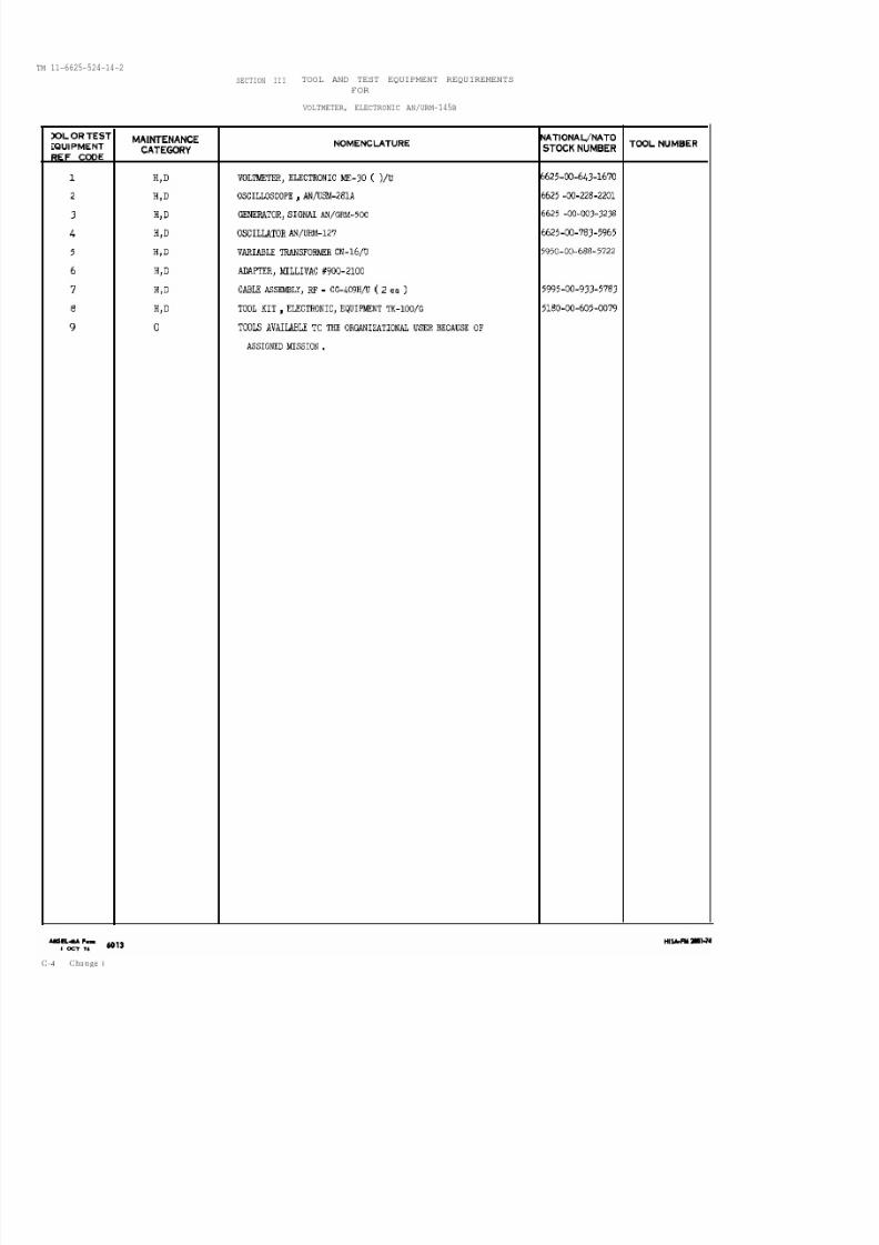
8/10/2019 TM 11-6625-524-14-2_Voltmeter_AN_URM-145_1974
http://slidepdf.com/reader/full/tm-11-6625-524-14-2voltmeteranurm-1451974 44/53
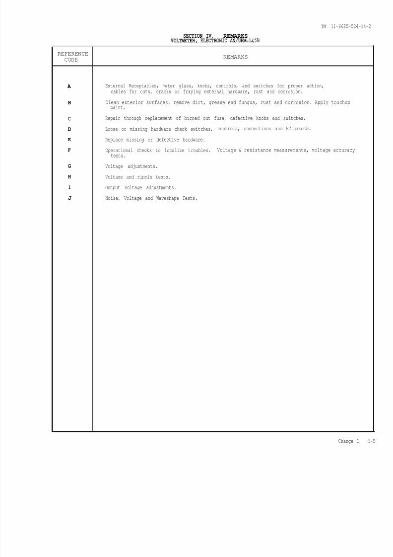
8/10/2019 TM 11-6625-524-14-2_Voltmeter_AN_URM-145_1974
http://slidepdf.com/reader/full/tm-11-6625-524-14-2voltmeteranurm-1451974 45/53
TM 11-6625-524-14-
SECTION IV. REMARKS
REFERENCE
CODEREMARKS
A External Receptacles, meter glass, knobs, controls, and switches for proper action,cables for cuts, cracks or fraying external hardware, rust and corrosion.
B Clean exterior surfaces, remove dirt, grease end fungus, rust and corrosion. Apply touchuppaint.
C Repair through replacement of burned out fuse, defective knobs and switches.
D Loose or missing hardware check switches, controls, connections and PC boards.
E Replace missing or defective hardware.
F Operational checks to localize troubles. Voltage & resistance measurements, voltage accuracytests.
G Voltage adjustments.
H Voltage and ripple tests.
I Output voltage adjustments.
J Noise, Voltage and Waveshape Tests.
Change 1

8/10/2019 TM 11-6625-524-14-2_Voltmeter_AN_URM-145_1974
http://slidepdf.com/reader/full/tm-11-6625-524-14-2voltmeteranurm-1451974 46/53

8/10/2019 TM 11-6625-524-14-2_Voltmeter_AN_URM-145_1974
http://slidepdf.com/reader/full/tm-11-6625-524-14-2voltmeteranurm-1451974 47/53
TM 11-6625-524-1
F i gu re 5 -9 . Regu l a ted powe r supp l y , simp l i f i e d schema t i c d i ag ra m

8/10/2019 TM 11-6625-524-14-2_Voltmeter_AN_URM-145_1974
http://slidepdf.com/reader/full/tm-11-6625-524-14-2voltmeteranurm-1451974 48/53

8/10/2019 TM 11-6625-524-14-2_Voltmeter_AN_URM-145_1974
http://slidepdf.com/reader/full/tm-11-6625-524-14-2voltmeteranurm-1451974 49/53

8/10/2019 TM 11-6625-524-14-2_Voltmeter_AN_URM-145_1974
http://slidepdf.com/reader/full/tm-11-6625-524-14-2voltmeteranurm-1451974 50/53
TM 11-6625-524-14-2
By Order of the Secretary of the Army:
Official:
VERNE L. BOWERS
Major General , Uni ted St ates Army,Th e Adj utant General .
Distr ibut ion:
F R E D C . WE Y A N D
Genem l, U ni ted States ArmyVi ce Chi ef of Staff .
To be distributed in accordance with DA Form 12-36, Direct and General
Su pport m a int ena nce requ iremen ts f or AN/ARC-102 a nd AN/TSQ -72. a nd D A
Form 12-51 Direct a nd G enera l Support ma intena nce requirement s for AN/G RC-
106, AN/G RC -108 a n d AN /TRC -90.

8/10/2019 TM 11-6625-524-14-2_Voltmeter_AN_URM-145_1974
http://slidepdf.com/reader/full/tm-11-6625-524-14-2voltmeteranurm-1451974 51/53

8/10/2019 TM 11-6625-524-14-2_Voltmeter_AN_URM-145_1974
http://slidepdf.com/reader/full/tm-11-6625-524-14-2voltmeteranurm-1451974 52/53
THE METRIC SYSTEM AND EQUIVALENTS

8/10/2019 TM 11-6625-524-14-2_Voltmeter_AN_URM-145_1974
http://slidepdf.com/reader/full/tm-11-6625-524-14-2voltmeteranurm-1451974 53/53