tm 11-5820-398-12 - n3oc - dyn 11-5820-398-12.pdf · condensed operating instructions for radio set...
TRANSCRIPT

TM 11-5820-398-12D E P A R T M E N T O F T H E A R M Y T E C H N I C A L M A N U A L
OPERATOR AND ORGANIZATIONAL MAINTENANCE MANUALINCLUDING REPAIR PARTS AND
SPECIAL TOOLS LISTS
RADIO SET AN/PRC-25( N S N 5 8 2 0 - 0 0 - 8 5 7 - 0 7 5 9 )
(INCLUDING RECEIVER-TRANSMITTERRADIO RT-505/PRC-25)
( 5 8 2 0 - 0 0 - 8 5 7 - 0 9 3 4 )
This copy is a reprint which includes currentpages from Changes 1 through 6.
HEADQUARTERS, DEPARTMENT OF THE ARMYNOVEMBER 1965

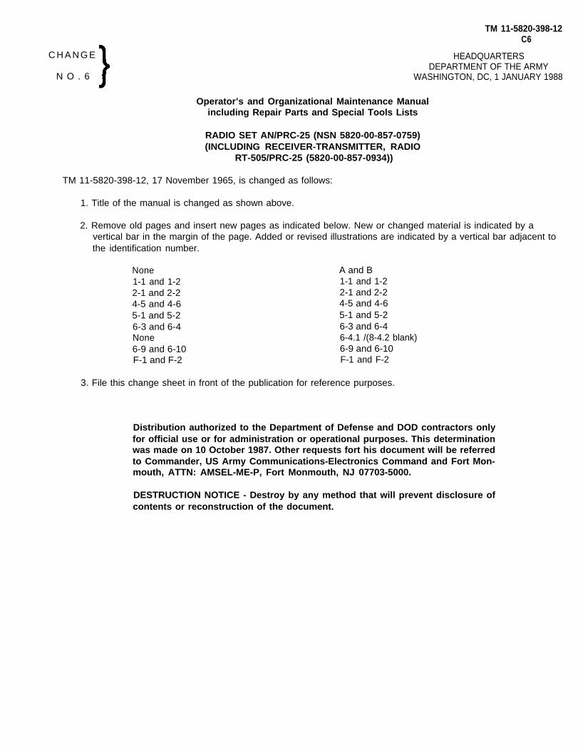
C O N D E N S E D O P E R A T I N G I N S T R U C T I O N S
F O R R A D I O S E T A N / P R C - 2 5
TO OPERATE SETA THE NUMBERS OF STEPS I THROUGH 6 BELOW RELATE TO THE NUMBERS ON THE DIAGRAM
(I)
(2)
(3)
(4)
(5)
(6)
(8)
(9)
INSTALL THE ANTENNA REQUIRED FOR THE TYPE OF OPERATION IN THE ANT MOUNT
ATTACH HANDSET H-138/U TO EITHER AUOIO CONNECTOR.
TURN THE FUNCTION SWITCH TO ON,
TURN THE BANO SWITCH TO THE DESIRED OPERATING FREQUENCY BAND,
TURN THE MC TUNING AND KC TUNING CONTROL KNOBS UNTIL THE DESIRED FREQUENCYAPPEARS IN THE CHANNEL DIAL (7).
TURN THE VOLUME CONTROL TO 4.
PRESS THE HANDSET H-138/U PUSH-TO-TALK SWITCH AND SPEAK INTO HANDSET. RELEASETHE PUSH-TO-TALK SWITCH TO LISTEN.
ADJUST THE vOLUME CONTROL (6) FOR A DESIRABLE SOUND LEVEL,
TO REDUCE THE RUSHING NOISE WHEN NO SIGNAL IS BEING RECEIVED, TURN SWITCH (3) TO SQUELCH,
(7)
TO TURN SET OFF B. TURN THE FUNCTION SWITCH (3) TO OFF.
T M 5 8 2 0 - 3 9 8 - 1 0 - 1 2
Figure A. Condensed operating instructions for Radio Set AN/PRC-25
TM 11-5820-398-12C6
C H A N G E HEADQUARTERSDEPARTMENT OF THE ARMY
WASHINGTON, DC, 1 JANUARY 1988N O . 6
Operator’s and Organizational Maintenance Manualincluding Repair Parts and Special Tools Lists
RADIO SET AN/PRC-25 (NSN 5820-00-857-0759)(INCLUDING RECEIVER-TRANSMITTER, RADIO
RT-505/PRC-25 (5820-00-857-0934))
TM 11-5820-398-12, 17 November 1965, is changed as follows:
1. Title of the manual is changed as shown above.
2. Remove old pages and insert new pages as indicated below. New or changed material is indicated by avertical bar in the margin of the page. Added or revised illustrations are indicated by a vertical bar adjacent tothe identification number.
None1-1 and 1-22-1 and 2-24-5 and 4-65-1 and 5-26-3 and 6-4None6-9 and 6-10F-1 and F-2
A and B1-1 and 1-22-1 and 2-24-5 and 4-65-1 and 5-26-3 and 6-46-4.1 /(8-4.2 blank)6-9 and 6-10F-1 and F-2
3. File this change sheet in front of the publication for reference purposes.
Distribution authorized to the Department of Defense and DOD contractors onlyfor official use or for administration or operational purposes. This determinationwas made on 10 October 1987. Other requests fort his document will be referredto Commander, US Army Communications-Electronics Command and Fort Mon-mouth, ATTN: AMSEL-ME-P, Fort Monmouth, NJ 07703-5000.
DESTRUCTION NOTICE - Destroy by any method that will prevent disclosure ofcontents or reconstruction of the document.

By Order of the Secretary of the Army:
CARL E. VUONOGeneral, United States Army
Official: Chief of Staff
R.L. DILWORTHBrigadier General, United States Army
The Adjutant General
D I S T R I B U T I O N :T o b e d i s t r i b u t e d i n a c c o r d a n c e w i t h D A F o r m 1 2 - 5 1 l i t e r a t u r e
requirements for AN/PRC-25.

TM 11-5820-398-12C 5
C H A N G E} HEADQUARTERSDEPARTMENT OF THE ARMY
WASHINGTON, DC, 22 January 1979N O . 5
Operator’s and Organizational Maintenance ManualIncluding Repair Parts and Special Tools Lists
RADIO SET AN/PRC-25 (NSN 5820-00-857-0759)(INCLUDING RECEIVER-TRANSMlTTER, RADIO
RT-505/PRC-25 (5820-00-857-0934))
TM 11-5820-39%12, 17 November 1965, is changed as follows:
1. The title of the manual is changed to read as indicated above.
2. Changed material is indicated by a bar in the margin. New chapters, paragraphs andappendixes are indicated by a bar in the caption.
3. Remove and insert pages as indicated below:
Remove pages Insert pagesi through iii.............................................................i and ii1-1 through 1-2.1....................................................................1-1 through 1-2.12-1trough2-4............................................................................2-1 through 2-43-1 through 3-4......................................................................3-1 through 3-44-1 through 4-3...............................................................4--1 through 4--65-1 through 5-5................................................................5-1 through 5-66-9 through 6-12................................................................6-9 through 6-126-15 and 6-16.................................... .................................6-15 and 6-167-1 and 7-2............................................................................7-1A-I-1 and AI-2.......................................................................A-1 and A-2AII-1 and AII-2........................................................................B-1 and B-2AIV-3 through AIV-6.........................................................................................................................................................E-1 and E-2..............................................................................................F-1 and F-2
. . . . . . . . . . . . . . .
4. File this change sheet in the front of the manual for reference purposes.
By Order of the Secretary of the Army:
BERNARD W. ROGERSGeneral, United States Army
Official: Chief of Staff
J. C. PENNINGTONBrigadier General, United States Army
The Adjutant General


TM 11-5820-398-12C 4
HEADQUARTERS,DEPARTMENT OF THE ARMYWASHINGTON DC, 20 August, 1974
Operator’s and Organizational Maintenance ManualIncluding Repair Parts and Special Tools Lists
RADIO SET AN/PRC-25
( INCLUDING RECEIVER-TRANSMITTER, RADIO RT-505 /PRC-25)
TM 11–5820-398–12, 17 November 1965, is changed as follows:
1. A vertical bar appears opposite changed material:
2. Remove and insert pages as indicated in the page list below:
Remove Pages
f and ii
1-1 and 1-2
AII-1 through AII-4
Insert Pages
i through iii
1-1 through 1-2.1
AII-1 through AII-2
3. File this change sheet in the front of the manual for reference purposes.
By Order of the Secretary of the Army:
CREIGHTON W. ABRAMSGeneral, United States Army
Official: Chief of Staff
VERNE L. BOWERS.Major General, United States ArmyThe Adjutant General
Distribution:
To be distributed in accordance with FA Form 12-51, Operator maintenance requirements forAN/GRC-125, AN/PRC-25 and AN/VRC-53.
TAGO 3141A


CHANGE
N o . 3
TM 11-5820-398-12C3
H E A D Q U A R T E R SDEPARTMENT OF THE A R M Y
W A S H I N G T O N, D. C. 10 October 1970
Operator and Organizational Maintenance Manual
Including Repair Parts and Special Tool Lists
RADIO SET AN/PRC-25
(INCLUDING RECEIVER-TRANSMITTER, RADIO RT-505/PRC-25)
TM 11-5820–398-12, 17 November 1965, is changed as follows:
1. The title of the manual is changed as indicated above.
2. Remove and insert pages as indicated b e l o w :
Remove insert
i and ii i and ii1-1 through 1-4 1-1 through 1-42-1 through 2-4 2-1 through 2-43-1 through 3-8 3-1 through 3-84-1 through 4-3 4-1 through 4-35-1 through 5-11 5-1 through 5-66-1 through 6-4 6-1 through 6-46-13 and 6-14 6-13 and 6-146-19 and 6-20 6-19 and 6-206-25 (fig. 6-17) 6-25 (fig. 6-17)AI-1 and AI-2 AI-1 and AI-2AII-1 through AII-4 AII-1 through AII-4AIII-1 through AIII-8 AIII-1 through AII-6AIV-1 through AIV-11 AIV-1 through AIV-10
3. Page 2 of cover .
A (2). Delete H-138/U.A (7). Delete H-138/U,
4. File this change sheet in front of the publication for reference purposes.
By Order of the Secretary of the Army:
Official:
KENNETH G .Major General,
W. C. WESTMORELAND,General, United States Army,Chief of Staff.
WICKHAM,United States Army,
The Adjutant General.
Distribution:
To be distributed in accordance with DA Form 12-51, organizational maintenance requirements for AN/GRC-125, AN/PRC-25, and AN/VRC-53 radio sets.


TM 11-5820-398-12C 2
C H A N G E} H E A D Q U A R T E R SDEPARTMENT OF THE ARMY
W ASHINGTON , D. C., 23 Octobcr 1 9 6 8N O . 2
Operator and Organizational Maintenance Manual
Including Repair Parts and Special Tool Lists
RADIO SET AN/PRC-25
TM 11–5820498–12, 17 November 1965, is changed as fo!lows:
1. Remove old pages and insert new pages as indicated below.
Remove pages
iand ii1-1 through 1-32-53-3 through 3-55-3 through 5-56-1 through 6-9AI-1AII-1 through AII-3AIII-3 through AII-8
Insert pages
iand ii1-1 through 1-52-5 and 2-63-3 through 3-85-3 through 5-116-1 through 6-25AI-1 through AI-2AII-1 through AII-4AIII-3 through AIII-8
Insert figure7-2 (fold-in)
2. File this change sheet in front of the publication for reference purposes.
By Order of the secretary of the Army:
Official:
KENNETH G. WICKHAM,Major General, United States Army,The Adjutant General.
Distribution:
W. C. WESTMORELAND,General, United States Army,Chief of Staff.
To be distributed in accordance with DA Form 12-51 (qty rqr Block #326) requirements for Organizationalmaintenance, AN/PRC-25 Radio Set.


CHANGES }TM 11-5820-398-12
Cl
H E A D Q U A R T E R S ,DEPARTMENT OF THE ARMY
W ASHINGTON , D. C., 29 September 1966
O r g a n i z a t i o n a l M a i n t e n a n c e M a n u a l
N O . 1
TM 11-5820-398-12,
1. Remove and insert
Including Repair Parts and Special
RADIO SET AN/PRC-25
17 November 1965, is changed to
pages as indicated below.
Remove pages
Tool Lists
add technical information.
Insert pagesAIV-3 and AIV-4 AIV-3 through AIV-11
2. Retain this transmittal sheet in the front of the manual for future reference.
By Order of the Secretary of the Army:
Official:
KENNETH G. WICKHAM,Major General, United States Army,The Adjutant General.
Distribution:Active Army
USASA (2)CNGB (1)OCC-E (7)Dir of Trans (1)CofEngrs ( 1 )TSG (1)CofSptS (1)USAARENBD (2)USAAESWBD (5)USAAVNTBD (5)USAIB (5)USACDCEA (1)USACDCCBRA ( 1 )USACDCCEA (1)USACDCCEA Ft Huachuca (1)USACDCOA (1)USACDCQMA (1)USACDCTA (1)USACDCADA (1)USACDCARMA(1)USACDCAVNA (1)USACDCARTYA(1)USACDCSWA (1)USAMC (5)USCONARC (5)
HAROLD K. JOHNSON,General, United States Army,Chief of Staff.
ARADCOM (5)ARADCOM Rgn (2)OS Maj Comd (4)USACSS (5)LOGCOMD (2)USAMICOM (4)USASTRATCOM (4)USASTRATCOM-EUR (10)USARYIS (5)USAREUR (5)USAESC (85)USACOMZEUR (5)MDW (1)Armies (2) except
USARAL (8)7th USA (8)8th USA (8)
corps (2)USAC (3)1st GM Bde (5)9th USASA Fld Sta (5)12th USASA Fld Sta (5)Svc Colleges (2)
USASOS (5)
U S A S E S C S ( 6 0 )

USAADS (2)USAAMS (30)USAARMS (30)USAIS (30USAES (2)MFSS (5)USMA (5)USMPS (5)USATSCH (5)Frankford Arsenal (5)Edgewood Arsenal (5)Redstone Arsenal (5)USATC Armor (2)USATC Engr (2)USATC Inf (2)USASTC (2)WRAMC (1)Army Pic Cen (2)USACDCEC (10)USAOEC (5)USATTC (5)Instl (2) except
Ft Hancock (4)Ft Carson (25)Ft Gordon (10)Ft Huachuca (10]WSMR (5)Ft Knox (12)DPG (5)Ft Lee (5)Ft Devens (5)Ft Belvoir (5)APG (5)USAEPG (5)
Army Dep (2) exceptLBAD (14)SAAD (30)TOAD (14)LEAD (7)SHAD (3)N AAD ( 5 )SVAD (5)CHAD (3)ATAD (10)TEAD (5)
GENDEPS (2)Sig Sec GENDEPS (5)Sig Dep (12)USABIOLABS (5)Sig FLDMS (2)AMC (1)USAERDAA (2)USAERDAW (13)USACRREL (2)MAAG Vietnam (5)KMAG (5)USASETAF (5)USARSG (5)Units org under fol TOE:
(2 cys each)1-71-371-471-56
1-591-751-761-771-781-1001-1011-1071-2071-2571-2581-3073-2675-75-255-265-275-355-375-1165-1295-1455-1465-1475-1485-1555-1565-2155-2175-500 (AA-A D, MC)6-376-1006-1016-1556-1566-1656-1666-1756-1766-1776-2006-2016-2156-2166-3006-3026-4366-3156-3166-317G-3196-3556-3566-3656-3666-4016-4056-4156-4166-4176-4196-4256-429
6-4356-4456-4496-5016-5256-5366-5556-5566-5576-5586-5756-5766-5776-5856-6156-6176-7006-7016-7056-7066-7076-7156-7166-7256-7267‘7-47-157-167-177-187-357-367-377-427-467-467-477-567-567-577-587-1008-268-268-279-7
9-179-229-479-1279-3779-51011-3511-3711-3811-3911-6711-9611-9711-9811-9911-11711-127

TM 11-5820-398-12
FIXED OPERATION WITH L0NG RANGE ANTENNAS
W A R N I N G
TELESCOPINGANTENNA MAST
TYPICAL TOWER EXTENDED RANGE DOUBLET ANTENNANTENNA
A
NEVER ERECT THESE LONG RANGE ANTENNAS DIRECTLY UNDER POWERLINES.
IF YOU MUST ERECT THESE LONG RANGE ANTENNAS NEAR POWERLINES, POWERLINE POLES ORTOWERS, OR BUILDINGS WITH OVERHEAD POWERLINE CONNECTIONS, NEVER PUT THE ANTENNACLOSER THAN TWO TIMES THE ANTENNA HEIGHT FROM THE BASE OF THE POWERLINE, POLE,TOWER OR BUILDINGS,
NEVER ATTEMPT TO ERECT ANY LONG RANGE ANTENNA WITHOUT A FULL TEAM.
BEFORE ERECTING ANY LONG RANGE ANTENNA, INSPECT ALL THE PARTS MAKING UP THEANTENNA KIT. DO NOT ERECT THE ANTENNA IF ANY PARTS ARE MISSING OR DAMAGED.
DO AS MUCH OF THE ASSEMBLY WORK AS POSSIBLE ON THE GROUND.
WHEN ERECTING THE ANTENNA, ALLOW ONLY TEAM PERSONNEL IN THE ERECTION AREA.
MAKE SURE THAT THE AREA FOR THE ANCHORS IS FIRM. IF THE GROUND IS MARSHY OR SANDY,GET SPECIFIC INSTRUCTIONS FROM YOUR CREW CHIEF OR SUPERVISOR ON HOW TO REINFORCETHE ANCHORS.
WHEN SELECTING LOCATIONS FOR ANCHORS, AVOID TRAVELED AREAS AND ROADS. IF YOU CANNOTAVOID THESE AREAS, GET SPECIFIC INSTRUCTIONS FROM YOUR SUPERVISOR AS TO WHAT CLEAR–ANCE YOUR GUY WIRES AND ROPES MUST HAVE OVER THE TRAVELED AREAS AND ROAD.
CLEARLY MARK ALL GUY WIRES AND ROPES WITH THE WARNING FLAGS OR SIGNS SUPPLIED BY YOURuNIT. IN AN EMERGENCY, USE STRIPS OF WHITE CLOTH AS WARNING STREAMERS.
IF YOU SUSPECT THAT POWERLINES HAVE MADE ACCIDENTAL CONTACT WITH YOUR ANTENNA, STOPOPERATING, ROPE OFF THE ANTENNA AREA. AND NOTIFY YOUR SUPERIORS.
IF THE WEATHER IN YOUR AREA CAN CAUSE ICE TO FORM ON YOUR LONG RANGE ANTENNA AND ITSGUY WIRES AND ROPES, ADD EXTRA GUYS TO SUPPORT THE SYSTEM. ROPE OFF THE AREA ANDPOST IT WITH WARNING SIGNS LIKE “ BEWARE OF FALLING ICE."
DO NOT TRY TO ERECT ANY ANTENNA DURING AN ELECTRICAL STORM.
KEEP A SHARP EYE ON YOUR ANCHORS AND GUYS. CHECK THEM DAILY AND lMMEDIATELYBEFORE AND AFTER BAD WEATHER.
Change 6 A

TM 11-5820-398-12
Remove the ba t te ry f r om Bat te ry
b e i n g u s e d . T h i s i s r e q u i r e d t o
WARNING
Box CX-2562/PRC when RT-505/PRC is not
e n s u r e t h a t h y d r o g e n ( a b y - p r o d u c t o f
Magnes ium Bat te ry BA-4386 /U d i s charge a c t i on ) does no t a c cumula te .
P e r s o n n e l c a n b e i n j u r e d a n d e q u i p m e n t d a m a g e d i f t h e g a s e x p l o d e s .
WARNING
P r e v e n t p e r s o n n e l i n j u r y w h e n a p p l y i n g o r r e m o v i n g s t e e l s t r a p p i n g , b y
w e a r i n g h e a v y g l o v e s a n d a f a c e s h i e l d . D o n o t h a n d l e p a c k i n g c a r t o n s
b y t h e s t e e l s t r a p p i n g .
WARNING
Fumes of TRICHLOROTRIFLUOROETHANE are poisonous. Provide adequate vent-
ilation whenever you use TRICHLOROTRIFLUOROETHANE. Do not use solvent
n e a r h e a t o r o p e n f l a m e . TRICHLOROTRIFLUOROETHANE will not burn, but
hea t changes the gas in to po i sonous , i r r i ta t ing fumes . DO NOT brea the
the fumes o r vapors . TRICHLOROTRIFLUOROETHANE dissolves natural skin oils.
D O N O T g e t t h e s o l v e n t o n y o u r s k i n . U s e g l o v e s , s l e e v e s a n d a n a p r o n
w h i c h t h e s o l v e n t c a n n o t p e n e t r a t e . I f t h e s o l v e n t i s t a k e n i n t e r n a l l y ,
c o n s u l t a p h y s i c i a n i m m e d i a t e l y .
B Change 6
TM 11-5820-398-12
TECHNCAL MANUAL} HEADQUARTERS DEPARTMENT OF THE ARMY WASHINGTON, DC, 17 November 1965NO. 11-5820-398-12
OPERATOR’S AND ORGANIZATIONAL MAINTENANCE MANUALINCLUDING REPAIR PARTS AND SPECIAL TOOLS LISTS
R A D I O S E T A N / P R C - 2 5 ( N S N 5 8 2 0 - 0 0 - 8 5 7 - 0 7 5 9 )
(INCLUDING RECEIVER-TRANSMITTER, RADIO RT-505/PRC-25
( 5 8 2 0 - 0 0 - 8 5 7 - 0 9 3 4 ) )
ParagraphCHAPTER 1. INTRODUCTION
Section I. GeneralScope--------- - - - - - - - - - - - - - - - - - - - - - - - - - - - - - - - - - - - - - - - - - - - - - - - - - - - - - - - - - - - - - - - - - - - - - - -Indexes of publications - - - - - - - - - - - - - - - - - - - - - - - - - - - - - - - - - - - - - - - - - - - - Forms and records - - - - - - - - - - - - - - - - - - - - - - - - - - - - - - - - - - - - - - - - - - - - - - - - - - - - - - -Reporting equipment improvement recommendations- - - - - - - - - - - - - - - - - - - - Reporting of errors - - - - - - - - - - - - - - - - - - - - - - - - - - - - - - - - - - - - - - - - - - - - - - - - - - - - - - - - - - Administrative storage - - - - - - - - - - - - - - - - - - - - - - - - - - - - - - - - - - - - - - - - - - - - - - - - - - - Destruction of Army electronics materiel - - - - - - - - - - - - - - - - - - - - - - -
11. Description and DataPurpose and use - - - - - - - - - - - - - - - - - - - - - - - - - - - - - - - - - - - - - - - - - - - - - - - - - - - - - - - - - - - - -Technical characteristics - - - - - - - - - - - - - - - - - - - - - - - - - - - - - - - - - - - - - - - - - - - - - - - - - - - - - - -Items comprising an operable equipment - - - - - - - - - - - - - - - - - - - - - - - - - - - - - -General description - - - - - - - - - - - - - - - - - - - - - - - - - - - - - - - - - - - - - - - - - - - - - - - - - - - - - - - -Receiver-Transmitter, Radio RT-505/PRC-25 - - - - - - - - - - - - - - - - - - - -Minor components - - - - - - - - - - - - - - - - - - - - - - - - - - - - - - - - - - - - - - - - - - - - - - - - - - - - - - - - - - - -Additional equipment required- - - - - - - - - - - - - - - - - - - - - - - - - - - - - - - - - - - - - - - - - - - - - - -
CHAPTER 2. INSTALLATIONUnpacking- - - - - - - - - - - - - - - - - - - - - - - - - - - - - - - - - - - - - - - - - - - - - - - - - - - - - - - - - - - - - - - - - - - - -Checking unpacked equipment - - - - - - - - - - - - - - - - - - - - - - - - - - - - - - - - - - - - - - - - - - - - -Siting - - - - - - - - - - - - - - - - - - - - - - - - - - - - - - - - - - - - - - - - - - - - - - - - - - - - - - - - - - - - - - - - - - - - - - - - - - - - - - - -Installation of battery - - - - - - - - - - - - - - - - - - - - - - - - - - - - - - - - - - - - - - - - - - - - - - - - - - - - -Assembly and installation for man-pack operation - - - - - - - - - - - - - - - - -Installation of antenna - - - - - - - - - - - - - - - - - - - - - - - - - - - - - - - - - - - - - - - - - - - - - - - - - - - - - - - -
3. OPERATING INSTRUCTIONSReceiver-Transmitter Radio RT-505/PRC-25, controls, indicators, and connectors - - - -Presetting channel frequencies - - - - - - - - - - - - - - - - - - - - - - - - - - - - - - - - - - - - - - - - - - - - - - - - - - - - - - - - - -Selecting preset channels - - - - - - - - - - - - - - - - - - - - - - - - - - - - - - - - - - - - - - - - - - - - - - - - - - - - - - - - - - -Operating procedure - - - - - - - - - - - - - - - - - - - - - - - - - - - - - - - - - - - - - - - - - - - - - - - - - - - - - - - - - - - - - - -Stopping procedure - - - - - - - - - - - - - - - - - - - - - - - - - - - - - - - - - - - - - - - - - - - - - - - - - - - - - - - - - - - - - - - - -Recognition and identification of jamming - - - - - - - - - - - - - - - - - - - - - - - - - - - - - - - - - - - - - - - - - -Antijamming - - - - - - - - - - - - - - - - - - - - - - - - - - - - - - - - - - - - - - - - - - - - - - - - - - - - - - - - - - - - - - - - - - - - - - - - - -Operating procedures under arctic conditions - - - - - - - - - - - - - - - - - - - - - - - - - - - - - -- - - - - -Homing operation - - - - - - - - - - - - - - - - - - - - - - - - - - - - - - - - - - - - - - - - - - - - -Conditions for squelch and nonsquelch operation - - - - - - - - - - - - - - - - - - - - - - System application - - - - - - - - - - - - - - - - - - - - - - - - - - - - - - - - - - - - - - - - - - - - - - - - - - -
CHAPTER 4. OPERATOR’S MAINTENANCE lNSTRUCTIONSSection I. Preventive Maintenance
Scope of operator’s maintenance- - - - -- - - - - - - - - - - - - - - - - - - - - - - - - - - - - - - - - - - - - - - - - - - - - - - - - - - - - - - - -Preventive maintenance, general - - - - - - - - - - - - - - - - - - - - - - - - - - - - - - - - - - - - - - - - - - - - - - - - - - - - - - - - - - - - -.Cleaning - - - - - - - - - - - - - - - - - - - - - - - - - - - - - - - - - - - - - - - - - - - - - - - - - - - - - - - - - - - - - - - - - - - - - - - - - - - - - - - - - - - - -
1-11-21-31-3.11-3.21-3.31-3.4
1-41-51-61-71-81-91-10
2-12-22-32-42-52-6
3-13-23-33-43-53-63-73-83-93-103-11
4-14-24-4
Page
1-11-11-11-11-11-11-2
1-21-21-2.11-2.11-2.11-2.11-3
2-12-12-12-22-32-5
3-13-23-33-33-53-53-53-53-53-63-6
4-14-14-5
l This manual supercedes TM 11-5820-398-10, 29 October 1962, including C 4, 30 July 1965; TM 11-5820-98-20, 3 December1962, including C 1, 11 April 1963; TM 11-5820-398-20P, 17 November 1964; and TM 11-5820-497-20P, 21 April 1964.
C h a n g e 5

TM 11-5820-398-12
Paragraph Page II. Troubleshooting
Visual inspection---- - - - - - - - - - - - - - - - - - - - - - - - - - - - - - - - - - - - - - - - - - - - - - - - - - - - - - - - - - - -Troubleshooting --------------------------------------------------------------------
CHAPTER 5. ORGANIZATIONAL MAINTENANCESection 1. General
Scope of organizational maintenance ------------------------------------------------Tools, materials, and test equipment required ----------------------------------------
II. Preventive MaintenanceOrganizational preventive maintenance checks and services (PMCS) ------------------
111. TroubleshootingVisual inspection --------------------------------------------------------------------Equipment performance checklist ----------------------------------------------------Repair and replacement parts --------------------------------------------------------Use of Test Sets, Radio Frequency AN/USM-182 and TS-2600/U ----------------------
CHAPTER 6. MATERIEL USED IN CONJUNCTION WITH RADIO SET AN/PRC-25Radio relay procedures and Retransmission Cable Kit MK-456(•)/GRC ----------------Battery, Dry BA-398/U for Arctic operation ------------------------------------------Antenna Equipment RC-292 --------------------------------------------------------Antenna, Homing Loop AT-784/PRC ------------------------------------------------Antenna AT-984A/G, installation and maintenance ----------------------------------Loudspeaker, Electromagnetic LS-549/PRC (deleted) --------------------------------Radio Set Control Group AN/GRA-39(•) ----------------------------------------------Radio Set Control AN/GSA-7 and Oscillator, Audio Frequency O-574/GRA- - - - - - - - - -Control Group AN/GRA-6- - - - - - - - - - - - - - - - - - - - - - - - - - - - - - - - - - - - - - - - - - - - - - - - - - - - -
7. SHIPMENT AND LIMITED STORAGEDisassembly of equipment ----------------------------------------------------------Repackaging for shipment or limited storage ----------------------------------------
A P P E N D I X A. REFERENCES -------------------------------------------------------------------------
4-44-6
5-l5-2
5-3
5-45-55-65-7
6-l6-26-36-46-56-66-76-86-9
7-17-2
- - - - - - - -
4-5
4-5
5-1
5-1
5-1
5-35-35-35-5
6 - 16 - 46 - 46 - 46 - 66 - 96 - 96-126-21
7 - 17 - 1
A-lB. COMPONENTS OF END ITEM LIST
Section I. Introduction - - - - - - - - - - - - - - - - - - - - - - - - - - - - - - - - - - - - - - - - - - - - - - - - -- - - - - - - - - - - - - - - - - - - - - - - - - - - - - - - - B-1 II. Integral Components of End Item - - - - - - - - - - - - - - - - - - - - - - - - - - - - - - - - - - - - - - - - - - - - - - - - - - - - - - B-2
APPENDIX III. MAINTENANCE ALLOCATIONSection 1. Introduction - - - - - - - - - - - - - - - - - - - - - - - - - - - - - - - - - - - - - - - - - - - - - - - - - - - - - - - - - - - - - - - - AIII-1
II. Maintenance Allocation Chart ---------------------------------------------------------------- AIII-3
APPENDIX IV. ORGANIZATIONAL MAINTENANCE REPAIR PARTS AND SPECIAL TOOLS LISTsection I. Introduction ---------------------------------------------------------------------------------- AIV-1
II. NoneIII. NoneIV. NoneV. None
VI. NoneVIII. Repair Parts for Organizational Maintenance (RT-505/PRC-25) - - - - - - - - - - - - - - - - - - - - - - - - - - - - AIV-7
IX. NoneX. Index—Federal Stock Number Cross-Reference to Figure and Item Number or Reference
Designation -------------------------------------------------------------------------------- AIV-8XI. Index—Reference Designation Cross-Reference to Page Number (RT-505/PRC-25) ------------ AIV-9
APPENDIX E. ADDITIONAL AUTHORIZATION LISTSection 1. Introduction ---------------------------------------------------------------------------------- E-l
II. Additional Authorization List ---------------------------------------------------------------- E-2
APPENDIX F. EXPENDABLE SUPPLIES AND MATERIALS LISTSection 1. Introduction - - - - - - - - - - - - - - - - - - - - - - - - - - - - - - - - - - - - - - - - - - - - - - - - - - - - - - - - - - - - - - - - - - - - - - - F-1
II. Expendable Supplies and Materials List ------------------------------------------------------- F-2
ii Change 5


TM 5820-398-10-1
Figure 1-1. Radio Set AN/PRC-25 in operation.
i v
TM 1-5820-398-12
C H A P T E R 1
I N T R O D U C T I O N
Section I.
1-1 Scope
a. This manual describes Radio Set AN/PRC-25 andcovers its installation, operation, and operator’s and organ-izational maintenance. It includes instructions for cleaning,checking, and inspecting the equipment.
b. The basic issue items list, maintenance allocationchart, and the organizational repair parts and special toollists are also included in this manual. An items troopinstalled or authorized list is not applicable to this equip-ment.
1-2 Consolidated index of Army Publications andBlank Forms
Refer to the latest issue of DA Pam 25-30 to determinewhether there are new editions, changes, or additionalpublications pertaining to the equipment.
1-3 Maintenance Forms, Records, and Reports
a. Reports of Maintenance and Unsatisfactory Equip-ment. Department of the Army forms and procedures usedfor equipment maintenance will be those prescribed by DAPam 738-750, as contained in Maintenance ManagementUpdate.
b. Report of Packaging and Handling Deficiencies. Fillout and forward SF 364 (Report of Discrepancy (ROD)) asprescribed in AR 735-11-2/DLAR 4140.55/NAVMATINST4355.73B/AFR 400-54/MCO 4430.3H.
c. Discrepancy in Shipment Report (DISREP) (SF 361).Fill out and forward Discrepancy in Shipment Report(DISREP) (SF 361) as prescribed in AR 55-38/NAVSU-
PINST 4610.33C/AFR 75-18/MCO P4610.19D/DLAR500.15.
GENERAL
1-3.1 Reporting Equipment improvementRecommendations (EIR)
a. Army. If your equipment needs improvement, let usknow. Send us an EIR. You, the user, are the only one whocan tell us what you don’t like about the design. Put it on anSF 368 (Quality Deficiency Report). Mail it to Commander,US Army Communications-Electronics Command and FortMonmouth, ATTN: AMSEL-PA-MA-D, Fort Monmouth,New Jersey 07703-5000. We’ll send you a reply.
1-3.2 Repotting Errors and RecommendingImprovements
You can help us improve this manual. If you find anymistakes or if you know of a way to improve the procedures,please let us know. Mail your letter or DA Form 2028(Recommended Changes to Publications and BlankForms) direct to: Commander, US Army Communications-Electronics Command and Fort Monmouth, ATTN: AM-SEL-ME-MP , Fort Monmouth, New Jersey 07703-5000.
1-3.3 Adminis t rat ive Storage
Administrative storage of the AN/PRC-25 will be handledas follows:
a. Remove the battery; clean the battery compartment.b. Before and after storage, perform the following:
(1) Inventory the equipment (app II).(2) Clean the equipment (para 4-6).(3) Check the operation of the equipment (para 5-7),
c. During storage, inventory the equipment and performan operational test of sidetone.
Change 6 1-1

TM 11-5820-398-12
These checks may be done approximately every3 or 4 months.
d. Store the equipment in a dry and moisture-free area with safeguards against pilfering.
1-3.4. Destruction of Army Electronics
Materiel
Destruction of Army electronics materiel toprevent enemy use shall be in accordance withTM 750-244-2.
Section Il. DESCRIPTION AND DATA
1-4. Purpose and Use(fig. l-l)
u. Radio Set AN/PRC-25 is a short-range,manpack portable, frequency modulated (FM) re-ceiver-transmitter used to provide two-way voicecommunication.
b. Receiver-Transmitters, Radio RT-505/PRC-25 and RT-505A/PRC25, part of the AN/PRC-25, are also used as part of vehicular RadioSets AN/VRC-53 and AN/GRC-125 (TM 11-5820498-12).
c. FM radio sets with which the AN/PRC25can communicate are listed in paragraph 3-11(fig. 3-3).
d. The AN/PRC-25 can also be used in con-junction with other equipment ((1) through (6)below).
(1) The AN/PRC-25 can be connected toother FM radio sets for radio relay use bymeans of Retransmission Cable Kit MK-456(*)/GRC (para 6-1) (TM 11-5995-202-15). TypicalFM radios include:
(a) AN/PRC-25 and AN/PRC-77 (TM 11-5820-667-12).
(b) Vehicular versions and manpack ra-dios: AN/VRC-53, AN/VRC-64, AN/GRG-125,and AN/GRC-160 (TM 11-5820498-12).
(c ) AN/VRC-12 series radios (TM 11-5820-101-12).
(2) Remote control of the AN/PRC-25 canbe provided by Radio Set Control Group AN/GRA-39(*) (para 6-7) and Radio Set ControlAN/GRA-6 (para 6-9a).
(3) Radio wire integration (RWI) operationwith the AN/PRC-25 and remote telephonefacilities can be provided by Radio Set ControlAN/GSA-7 with Oscillator O-574/GRC (para 6 -8). Also, the AN/GRA-39(*) and AN/GRA-6 canbe used with the AN/PRC-25 for RWI (para 6-7b and 6-9b).
(4) The AN/PRC-25 can be used with An-tenna, Homing Loop AT-784/PRC (para 6-4) for
detection and location of homing beacons orother FM radios.
(5) The AN/PRC-25 can be used with An-tenna AT-984A/G (para 6-5), a long-wire, multi-ple-wavelength antenna, to extend the trans-mission and reception ranges.
(6) Antenna Equipment RC-292 (TM 11-5820-348-15) and Antenna Group OE-254/GRC(TM 11-5985-357-13) can be used in place of thewhip antennas to extend the communicationdistance (para 6-3).
1-5. Technical Characteristics
Frequency rangeLow band ------------ 30.00 to 52.95 mc.High band ------------ 53.00 to 75.95 mc.
Number of channels ------ 920.Channel spacing ---------- 50 kc.Types of transmission and reception:
Transmission -------- Voice and 150-cps squelchtone.
Reception ------------ Voice (no squelch); or voiceand 150-cps squelch tone.
Transmission and reception power requirements:Transmission --------
Reception _______Type of modulation --------Transmitter output powerType of squelch ----------
Distance range ------------
Types of antennas:Short antenna --------
Long antenna _____
Power source ------------
Battery life ________
2.5 to 3 vdc, 0.4 amp; 12.5 to15 vdc, 1.4 amp.
12 to 15 vdc, 0.6 amp.Frequency.1.1 to 2-0 watts.Tone operated by 150-cps
signal.5 miles (8 kilometers varies
with conditions).
Antenna AT-892/PRC-25; 3feet long, semirigid steeltape.
Antenna AT_271/PRC; 10feet long, multisectionwhip.
Batteries, Dry BA-4386/U,BA-398/U (para 1-10).
60 hours (with a 9-to-1receiver-transmit ratio).
1-2 Change 6
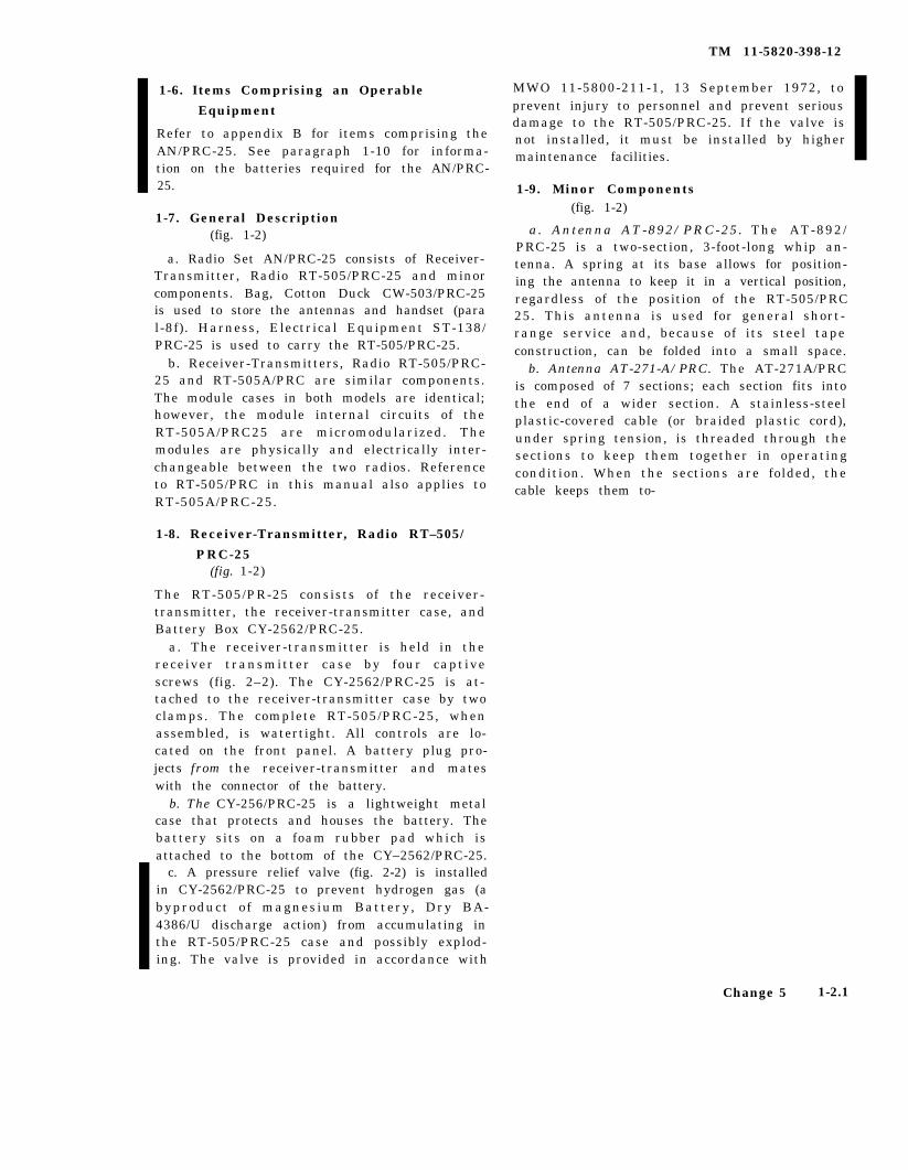
1-6. Items Comprising an Operable
Equipment
Refer to appendix B for items comprising theAN/PRC-25. See paragraph 1-10 for informa-tion on the batteries required for the AN/PRC-25.
1-7. General Description(fig. 1-2)
a. Radio Set AN/PRC-25 consists of Receiver-Transmitter, Radio RT-505/PRC-25 and minorcomponents. Bag, Cotton Duck CW-503/PRC-25is used to store the antennas and handset (paral-8f). Harness, Electrical Equipment ST-138/PRC-25 is used to carry the RT-505/PRC-25.
b. Receiver-Transmitters, Radio RT-505/PRC-25 and RT-505A/PRC are similar components.The module cases in both models are identical;however, the module internal circuits of theRT-505A/PRC25 are micromodularized. Themodules are physically and electrically inter-changeable between the two radios. Referenceto RT-505/PRC in this manual also applies toRT-505A/PRC-25.
1-8. Receiver-Transmitter, Radio RT–505/
PRC-25(fig. 1-2)
The RT-505/PR-25 consists of the receiver-transmitter, the receiver-transmitter case, andBattery Box CY-2562/PRC-25.
a. The receiver-transmitter is held in thereceiver transmitter case by four captivescrews (fig. 2–2). The CY-2562/PRC-25 is at-tached to the receiver-transmitter case by twoclamps. The complete RT-505/PRC-25, whenassembled, is watertight. All controls are lo-cated on the front panel. A battery plug pro-jects from the receiver-transmitter and mateswith the connector of the battery.
b. The CY-256/PRC-25 is a lightweight metalcase that protects and houses the battery. Thebattery sits on a foam rubber pad which isattached to the bottom of the CY–2562/PRC-25.
c. A pressure relief valve (fig. 2-2) is installedin CY-2562/PRC-25 to prevent hydrogen gas (abyproduct of magnesium Battery, Dry BA-4386/U discharge action) from accumulating inthe RT-505/PRC-25 case and possibly explod-ing. The valve is provided in accordance with
TM 11-5820-398-12
MWO 11-5800-211-1, 13 September 1972, toprevent injury to personnel and prevent seriousdamage to the RT-505/PRC-25. If the valve isnot installed, it must be installed by highermaintenance facilities.
1-9. Minor Components(fig. 1-2)
a. Antenna AT-892/PRC-25. The AT-892/PRC-25 is a two-section, 3-foot-long whip an-tenna. A spring at its base allows for position-ing the antenna to keep it in a vertical position,regardless of the position of the RT-505/PRC25. This antenna is used for general short-range service and, because of its steel tapeconstruction, can be folded into a small space.
b. Antenna AT-271-A/PRC. The AT-271A/PRCis composed of 7 sections; each section fits intothe end of a wider section. A stainless-steelplastic-covered cable (or braided plastic cord),under spring tension, is threaded through thesections to keep them together in operatingcondition. When the sections are folded, thecable keeps them to-
Change 5 1-2.1

TM 11-5820-398-12
gether as a group, to prevent the loss ofindividual sections. Spring tension is providedby a spiral spring in the base section. This an-tenna is used when maximum range is re-quired.
c. Support, Antenna AB-591/PRC-f?S. TheAB-591/PRC-25, which is of r igid tubularconstruction, is used as a main support of theA T - 2 7 1 A / P R C .
d. Harness, Electrical Equipment ST-138/PRC-25. The ST-138/PRC-25 is made of cot-ton duck. It is used to secure the RT-505/PRC-25 so that it can be carried on the oper-ator’s back.
e. Bag, Cotton Duck CW-503/PRC-25. T h eCW-503/PRC-25 is sectionalized into severalpockets which are used to store the two anten-nas and the handset.
f. Handset. Handset H-138 (*)/U (fig. 1 - 2 )(H-138(* ) /U represents the H-138/U andH - l 3 8 A / U ) o r H a n d s e t H - 1 8 9 / G R ( f i g .1-3) (handset) may be used with the AN/PRC-25 (radio set). Maintenance instructionsand repair parts lists for the H-138(*)/U a r egiven in TM 11-596,%257-15 and for the H-189/GR, in TM 11-5965-280-15. The handsetconsists of a microphone and a receiver section.
The retractable cord is terminated in a five-pinconnector. A push-to-talk switch is mountedin the handle. The H-138(*)/U microphonehas two elements, each under a separate open-ing, for cancellation of outside noise.
1-10. Additional Equipment Required(fig. 2-2)
a. Battery, Dry BA-386 PRC-25 or BA-4386/Uis not supplied as part of the AN/PRC-25 butis required for its use. The battery is supportedand housed in the CY-2562/PRC-25. Eitherbattery supplies 3 and 15 volts and is providedwith a female connector to mate with the RT-505/PRC-25 battery plug.
Note. All references in this manual to BA-386/PRC-25applies also to the BA-4386/U.
b. The BA-386/PRC-25is a standard carbon dry
cell battery; the BA-4386/U is a magnesiumcell battery that will operate the radio approx-imately twice as long as the BA-386/PRC-25.
c. For arctic operation, Battery, Dry BA-898/U may be used. See paragraph 6-2 fordetails.
Change 3 1 - 3

Figure 1-2.
TM
11-5820-398-12
1-4
C
ha
ng
e
3

C 2, TM 11-5820-398-12
TM5820-398-12-C2-7
Figure 1-3. Handout Handset H-189/GR, disassembled.
1 - 5


TM 11-5820-398-12
CHAPTER 2
INSTALLATION
2-1. Unpacking(fig. 2-1)
a. Packaginq Data. When pricked for ship-ment, the components of the AN/PRC-25 areplaced in an inner carton. A moisture-vapor-proof barrier is placed around the inner carton.This package is placed in an outer carton. Theouter carton is covered with a second moisture-vaporproof barrier and placed in a wooden pack-king box. The dimensions of the wooden packingbox are 17 inches deep, 13 inches wide, and 9¾inches high. The weight of the pricked equipment
WARNING
Prevent personal injury when applying or removingsteel strapping. Wear heavy gloves and a face shield.Do not handle packing cartons by the steel strapping.
Note. When unpacking equipment that is packed onlyin cartons, omit the procedure given in (1), (2), and(8) below.
(1) Cut and fold brick the metal strops.(2) Remove the nails from the top and one
side of the wooden packing box with anailpuller. Do not pry off the boards
Prying may damage the equipment.
(3) Open the moisture-vaporproof barrierthat covers the outer carton.
(4) Open the outer carton. open the secondmoisture-vaporproof barrier that coversthe inner carton.
(5) Remove and open the inner carton.(6) Remove the corrugated filler.(7) Remove and open the envelope that con-
tains the technical manuals.(8) Remove the major and minor compo-
nents.
2-2. Checking Unpacked Equipment
a. Inspect the equipment for possible damageincurred during shipment. If the equipment hasbeen damaged, report the damage on SF 364.
b. See that the equipment is complete as listedon the packing slip. If the packing slip is notavailable, check the equipment against the basicissue items list (app. II). Report all discrepan-cies in accordance with DA-Pam 738-750. Shortage ofa minor assembly or part that does not affectproper functioning of the equipment should notp r e v e n t u s e o f t h e e q u i p m e n t .
c. If the equipment has been used or recondi-tioned, see whether it has been changed by a modi-fication work order (MWO). If the equipmenthas been modified, the MWO number will appearon the front panel, near the nomenclature plate.Check to see whether the MWO number (if any)and appropriate notations concerning the modifi-cation have been entered in the equipment manual.
NOTE
Current MWO’S applicable to the equip-ment are listed in DA Pam 25-30.
Change 6 2-1

TM 11-5820-398-12
2-3. Siting
The AN/PRC-25 operates at low power and onhigh frequencies; therefore, the location of theequipment greatly affects its operating range.Normally, a line-of-sight range can be expected;that is, if the other station can be seen, satisfac-tory operation is probable. An intervening hillor tall building may hamper or prevent contactw i th the o ther s ta t i ons . Va l l eys , dense lywooded areas, and low places are poor sites,Location on a hilltop or a tower will increaseoperating distances. If possible, avoid locationsnear a source of electrical interference, such aspowerlines, telephone lines, radar sets, and fieldhospitals.
2-4. Installation of Battery(fig. 2-2)
Test Set, Battery AN/PSM-13 (TM 11-6625-823-15) may be used to check Battery, Dry BA-4386/U.
a. Stand the RT-505/PRC-25 on a level sur-face with its front panel facing downward.
b. Release the two clamps by pushing thetopmost part of each clamp down and awayfrom the case.
c. Remove the CY-2562/PRC-25.d. Inspect the radio connector; if it is dam-
aged or loose, the RT–505/PRC-25 must berepaired. Tighten the pressure test screw if itis not sealed with epoxy. Tighten the pressurerelief valve.
e. Position the new battery connector in linewith the radio connector until the two connec-tors are mated.
f. Install the CY-2562/PRC-25 on the RT-505/PRC-25 case and tighten the two clamps.
g. To remove the battery, perform proceduresin a, b, and c above.
NOTESRemove the battery when the equip-
ment is not in use for more than a day.Magnesium Battery, Dry BA-4386/U
does not require refrigeration beforeinitial use to retain its power. But,when it has been in use over approxi-mately 5 hours (approximately 10 per-cent of its power used), store the bat-tery in a cool and moisture-free area.This procedure will prolong its usefullife.
Figure 2-1. Tyical packing.
2--2 Change 6

TM 11-5820-398-12
Figure 2-2. Installation of battery in RT-505/PRC-25.
CAUTIONSObserve the following procedures todispose of a worn-out battery:
Do not compact or incinerate thebattery.
Do not dispose of the battery instreams, rivers, and oceans, etc. Ship-board users will retain the battery forshore disposal.
Dispose of the battery in a sanitarylandfill.
2–5. Assembly and Installation for ManpackOperation
a. Attach the ST–138/PRC-25 (fig. 2-3) to theRT-505/PRC-25 as instructed in (1) through (4)below.
NOTEinstall the battery in the RT-505/PRC-25 before proceeding (para 2-4, fig. 2-2).
(1) Place the ST–138/PRC-25 flat on a levelsurface with the metal braces facing up.
(2) Place the RT-505/PRC-25 on the ST-138/PRC-25 with its front panel toward the top andthe CY–2562/PRC-25 resting on the metalbraces of the ST-138/PRC-25.
Change 5 2-3

TM 11-5820-398-12
Figure 2-3. Installation of receiver-transmitter in ST-138/PRC-25.
2-4 Change 5

C 2, TM 11-5820-398-12
(3) Fasten the RT-505/PRC-25 to theST-138/PRC-25 with the two retaining straps;f eed the meta l - t ipped s t rap f r om be l ow ,through the center slot on the buckle and thendown through the end slot in the buckle.
(4) Clip the CW-503/PRC-25 to the ST-138/PRC-25.
b . Mount the ST -138 /PRC-25 ( f i g . 2 -4 )on the operator as follows:
(1) Install the desired antenna (para 2-6 ) .
(2) Connect the handset to one of theAUDIO connectors on the front panel of theR T - 5 0 5 / P R C - 2 5 .
(3) Place the ST-138/PRC-25, with theRT-505/PRC-25 attached, on the operator ’sback. Place the shoulder straps over the oper-ator’s shoulders.
(4) Feed the end of the right lower strapthrough the right shoulder strap ring. Feedthe metal tip of the strap from below, throughthe center slot in the buckle and then downthrough the end slot (fig. 2-3).
(5) Feed the end of the left lower strapthrough the ring of the left shoulder strap.Feed the metal tip of the strap from below,through the center slot in the buckle and thendown through the end slot in the buckle (fig.2 - 3 .
(6) Hook the two belt straps to the com-bat belt.
2-6. Installation of Antennas
Use the AT-892/PRC-25 (short antenna)when maximum range is not required, Usethe AT–271A/PRC (long antenna) when max-imum range is required.
a. Antenna AT-892/PRC-25. See d below.(1 ) Remove the c over f r om the ANT
mount (fig. 3-1 ).( 2 ) Sc rew the bo t t om o f the AT-892 /
PRC-25 into the ANT mount. Make sure AT–892/PRC-25 is t ightened down ful ly ; checkits tightness often. See caution in d below.
b. Antenna AT-271A/PRC.( 1 ) Remove the c over f r om the ANT
mount (fig. 3-1).( 2 ) Sc rew Suppor t , Antenna AB-591 /
PRC-25 into the ANT mount.
Figure 2-.4. Installation AN/PRC-25 for man-packoperation.
(3) Extend the AT-271A/PRC by hold-ing the base section (the heaviest section ) andcarefully whipping it outward. If all sectionsare not secure, repeat the procedure or insertthe sections individually by hand.
(4) Secure the extended AT-271A/PRCi n t o t h e A B – 5 9 1 / P R C - 2 5 . M a k e s u r e A T -
271A/PRC is tightened down fully; check itstightness often. See caution in d below.
c. Other antennus. To use other antennas,refer to paragraph 6–3 for ground-plane An-tenna Equipment RC-292 (for long-distance
2-5

C 2, TM 11-5820-398-12
operation), paragraph 6-4 for Antenna, Hom-ing Loop AT-784/PRC (to detect other radiostations) , and paragraph 8-6 for AntennaAT-984A/G (a long-wire antenna) .
d. Orientation of AT-892/PRC-25. The AT-892/PRC-25 ( f ig . 1-2) is “provided with aspring base to permit positioning the antennaother than vertically to the top of the receiver-transmitter. For beat communication, the an-tenna should be vertical to the ground (A andB, f ig . 2-6) . When the operator or the re-ceiver-transmitter is in a position other thanvertical, the antenna should be adjusted sothat it is vertical to the ground. If the verticalposition would reveal the operator’s location,the antenna can be positioned so that it ishorizontal to the ground (C, fig. 2-5). Underthis situation, the direction of communicationis broadside to the antenna.
Caution: If as little as one-sixteenth inchgap is allowed between the top of the whipantenna mount and the flat bottom of theantenna the antenna may break at this pointleaving the threaded portion in the antennamount. A plastic filling has been includedamong the threads but it may become wornand ineffective in preventing the antennafrom being unscrewed by vibration. To safe-guard the antenna periodically tighten it intothe antenna mount.
Figure 2-5. Orientation of AT-892/PRC-25 in various positions on user
2-6

TM 11-5820-398-12
CHAPTER 3
OPERATING INSTRUCTIONS
3 - 1 .
CAUTIONS
1. When an AN/PRC-25 is used less than 10 feet from Radio SetsAN/VRC-12 and AN/VRC-43 through -49, and similar radios that use Re-ceiver-Transmitters, Radio RT–246/VRC and RT–524/VRC, there is dangerthat the high transmitter power of these radio sets can damage 1st RF am-plifier module A3 in the receive circuit of the RT-505/PRC–25, even when itis turned off, unless module A3 has the words C R 1 M O D A D D E D on itscover, or unless module A33 is used. Accordingly, keep the AN/PRC–25 awayfrom these high power radio sets until the “unprotected” module A3 has beenreplaced with either one that has the words CR1 MOD ADDED on its coveror one that is marked A33. (Module A33 is the version used in RT-841/PRC-77 and may also be installed in the RT-505/PRC-25).
2. Do NOT change the mc and kc tuning controls or the BAND switchwhile the radio is keyed for transmission (handset push-to-talk switch de-pressed). Damage to modules in the radio may result or the wrong channelfrequency may be set up, thus preventing radio communication.
3. Battery power should be between 12.5 and 15 volts dc, with plus (+)applied to the B terminal on the battery connector (at the back of the re-ceiver-transmitter) and minus (–) applied to the A terminal. Do not inter-change these battery polarities; to do so results in damage to modules in theradio.
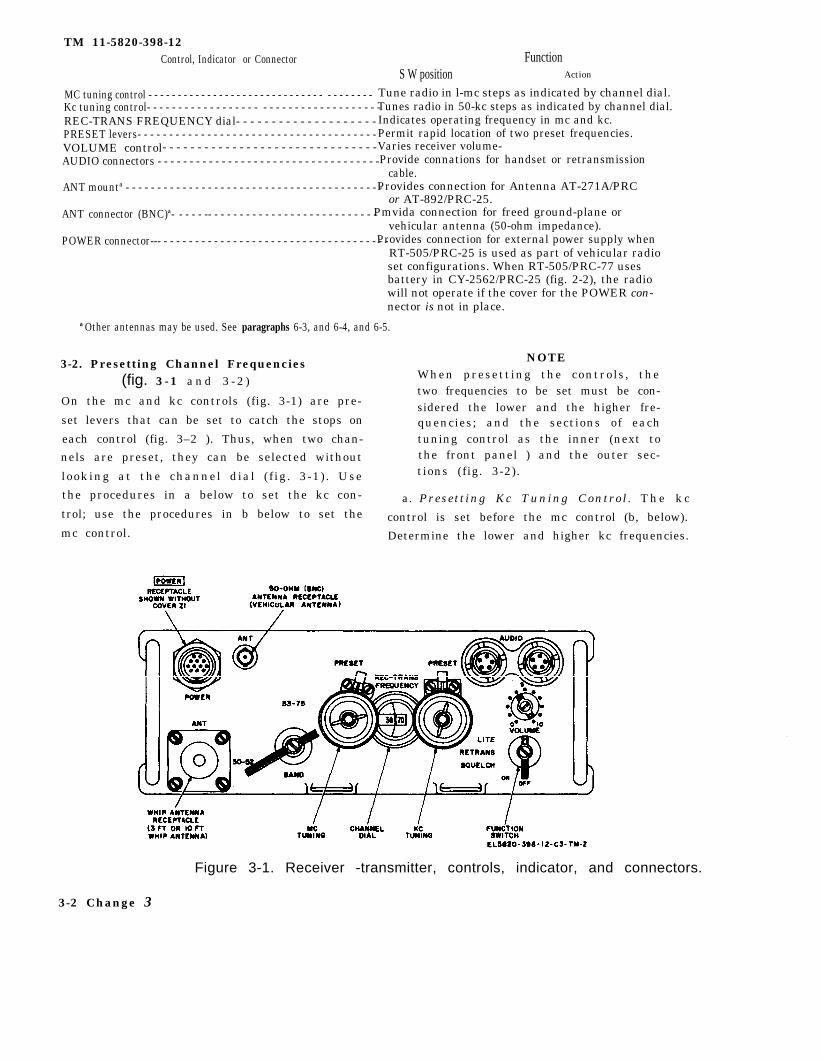
Receiver-Transmitter, Radio RT-505/PRC-25, Controls,Indicators, and Connectors
(fig. 3-1)
Control, Indicator or Connector
Function switch- - - - - - - - - - - - - - - - - - - - - - - - - - - - - - - - - - - - - - - -
s t o p srushing noise when no
FunctionS W position Action
O F F - - - - - - - - - - - - - - - - - - - - Turns off power.O N - - - - - - - - - - - - - - - - - - - - - - Applies power.SQUELCH----- - - - - - - - - - - Applies power and
BAND switch - - - - - - - - - - - - - - - - - - - - - - -
radio signal is received.RETRANS- - - - - - - - - - - - - - - - - - -Permits radio relay
operation.LITE----- - - - - - - - - - - - - - - - - Spring-loaded position;
lights channel dial.30-52 - - - - - - - - - - - - - - - - - - - - - Selects lower frequency
band, A band.53-75 - - - - - - - - - - - - - - - - - - -Selects higher frequency
band, B band.
Change 5 3 -1
TM 11-5820-398-12 Control, Indicator or Connector Function
S W position Action
MC tuning control - - - - - - - - - - - - - - - - - - - - - - - - - - - - - - - - - - - - - - Tune radio in l-mc steps as indicated by channel dial.Kc tuning control- - - - - - - - - - - - - - - - - - - - - - - - - - - - - - - - - - - - -Tunes radio in 50-kc steps as indicated by channel dial.REC-TRANS FREQUENCY dial- - - - - - - - - - - - - - - - - - - - Indicates operating frequency in mc and kc.PRESET levers- - - - - - - - - - - - - - - - - - - - - - - - - - - - - - - - - - - - - - Permit rapid location of two preset frequencies.VOLUME control- - - - - - - - - - - - - - - - - - - - - - - - - - - - - - -Varies receiver volume-AUDIO connectors - - - - - - - - - - - - - - - - - - - - - - - - - - - - - - - - - - - Provide connations for handset or retransmission
cable.ANT mountª - - - - - - - - - - - - - - - - - - - - - - - - - - - - - - - - - - - - - - - - -Provides connection for Antenna AT-271A/PRC
or AT-892/PRC-25.ANT connector (BNC)ª- - - - - -- - - - - - - - - - - - - - - - - - - - - - - - - - -Pmvida connection for freed ground-plane or
vehicular antenna (50-ohm impedance).POWER connector--- - - - - - - - - - - - - - - - - - - - - - - - - - - - - - - - - - - - -Provides connection for external power supply when
RT-505/PRC-25 is used as part of vehicular radioset configurations. When RT-505/PRC-77 usesbattery in CY-2562/PRC-25 (fig. 2-2), the radiowill not operate if the cover for the POWER con-nector is not in place.
ª Other antennas may be used. See paragraphs 6-3, and 6-4, and 6-5.
(fig. 3 - 1 a n d 3 - 2 ) 3-2. Presetting Channel Frequencies
On the mc and kc controls (fig. 3-1) are pre-
set levers that can be set to catch the stops on
each control (fig. 3–2 ). Thus, when two chan-
nels are preset, they can be selected without
looking at the channel dial ( f ig . 3-1) . Use
the procedures in a below to set the kc con-
trol; use the procedures in b below to set the
mc control.
NOTEWhen presetting the controls , thetwo frequencies to be set must be con-sidered the lower and the higher fre-quencies; and the sections of eachtuning control as the inner (next tothe front panel ) and the outer sec-tions (fig. 3-2).
a. Presett ing Kc Tuning Control . T h e k c
control is set before the mc control (b, below).
Determine the lower and higher kc frequencies.
Figure 3-1. Receiver -transmitter, controls, indicator, and connectors.
3-2 Change 3

(For example: 35 in 59.35 mc, 70 in 39.70mc, etc).
(1) Set the preset lever away from the kccontrol (A and B, fig. 3-2).
(2) Set the kc control so that the lowerfrequency appears on the channel dial.
(3) Posit ion the preset lever forwardagainst the control (C, fig. 3-2) and loosenthe wingnut on the control.
(4) Pull up on the lower section of thecontrol and turn it counterclockwise until thestop on the lower section strikes the preset le-ver. Tighten the wingnut.
(5) Position the preset lever away fromthe control.
(6) Turn the control unti l the higherfrequency appears in the channel dial (bothsections move).
(7) Loosen the wingnut and position thepreset lever forward against the control.
(8) Without disturbing the sett ing ofthe lower section, pull on the upper sectionand turn it clockwise until its stop strikes thepreset lever.
(9) Keeping the upper sect ion againstthe preset lever, tighten the wingnut.
(10) Check the settings for the lower andhigher kc frequency settings by turning thecontrol counterclockwise to the stop for thelower kc frequency, and clockwise to the stopfor the higher kc frequency.
(11 ) Set the mc control (b below).b. Presetting Mc Tuning Control. T h e m c
control is set after the kc control (a above).Determine the assigned lower and higher mcfrequencies. (For example: 59 in 59.35 mc, 3 9in 39.70 mc, etc).
(1) Prese t t ing mc f r equenc i e s in sameband. The procedure for presetting the lowerand upper sections of the mc control for mcfrequencies that are in the same band are thesame as those given for the kc control in aabove. That is, the lower mc frequency in theband is set with the lower section of the c o n -trol; and the higher mc frequency in the sameband is set with the upper section.
(2) Presetting mc frequencies in differ-ent bands. Note that three are 23 positions ofthe control in each band: from 30 through 52in band A; from 53 through 75 in band B.
TM 11-5820-398-12
(a) When presetting the mc controlfor frequencies that are in different bands, al-ways set the lower section to that mc frequen-cy that is lower in its band than the mc fre-quency in the other band. For example: 54 islower (second position) in band B than 33 m c( fourth posit ion) in band A; thus, 54 m cwould be set on the lower section and 33 m cwould be set on the upper section.
(b) To preset the mc control sections,use the same procedures in a above with theband switch in the proper position and withthe band switch in the proper position and withthe information given in (a) above.
3-3. Selecting Preset Channels(fig. 3-1 and 3-2)
To select a preset channel, proceed as fol-lows:
a. Set the PRESET levers forward (towardthe mc and kc tuning controls).
b. Set the BAND switch at 30-52 or 53-75,depending on the channel used.
c. Turn the mc and kc tuning controls untilthe stops strike against the PRESET levers.
d. Check the channel number that appearsin the channel dial.
e. If the incorrect channel appears in thechannel dial, turn the tuning controls againstthe stop in the opposite direction.
f. If the incorrect channel still appears, per-form the presetting procedures as given inparagraph 3–2.
g. To select the other preset channel, turnthe mc and kc tuning controls against the otherstops. If the preset frequency is in the otherband, set the BAND switchtion.
3-4. Operating Procedure(fig. 3-1)
a. Set the function switch
at the other posi-
to ON. A rushingn o i s e s h o u l d b e h e a r d i n t h e h a n d s e t . -
b. Set the BAND switch at 30-52 or 53-75,depending on the channel used.
NOTEIf a preset channel is to be used, selectthe preset channel as given in para-graph 3-3 in place of the procedurein c below. If a preset channel is not
Change 3 3 - 3
TM 11-5820-398-12
to be used, make sure that the PRE-SET levers are back (away from themc and kc tuning controls).D o n o t c h a n g e f r e q u e n c i e s o r t h eBAND switch while the radio is keyed(in transit mode).When using magnesium Battery, DryBA-4386/U, wait approximately 10 sec-onds after turning on the radio beforetransmitting (e below) to allow the bat-tery to develop full power.To obtain best operating range (dis-tance), keep the whip antenna verticalto the ground. See figure 2-5 for var-ious positions the user can positionhimself/herself to keep the short an-tenna vertical.
c. Turn the mc and kc tuning controls todisplay the desired frequency in the channeldial. See procedures in paragraph 3-3 to selectpreset channels.
d. Set the VOLUME control at position 4;readjust for a desired sound level in the hand-set.
e. Transmit as follows:(1) Press the handset push-to-talk switch.(2) Speak into the handset.
NOTEDo not speak into both elements of thehandset. It has two microphone ele-ments for noise cancellation; speakinginto both elements will cancel out thespeaker’s voice.
f. To receive, release the handset push-to-talkswitch.
g. The receiver rushing noise can be stoppedor reduced by setting the function switch toSQUELCH during periods when the other sta-tion is not transmitting. Refer to paragraph 3-10 for squelch operation conditions. To deter-mine whether squelch operation is possible, usethe following procedures:
(1) Arrange for the distant station to senda short transmission while operating withoutits squelch.
3-4 Change 5

TM 11-5820-398-12
Figure 3-2. Presetting mc and kc tuning controls
Change 3 3-4.1


(2) Set the function switch to ON; therushing noise should be heard until the otherstation transmits.
(3) Arrange with the other station toturn its squelch switch to the ON position andto send a short transmission.
( 4 ) On the RT-505 /PRC-25 ( r e ce iver -transmitter), s e t t h e f u n c t i o n s w i t c h t oSQUELCH; the rushing noise should stop andthe distant station should be heard when ittransmits.
(5) If the other station cannot be heardnow, reset the function switch to ON andadvise the other station of the situation,
Note. The failure of either station to receivetransmissions from the other may indicate that thedistance between the two stations is too great or thatthe squelch circuit of either radio station is defective.
(6) I f e ither stat ion is moving about,leave the function switches in the ON positionat both stations until it has been determined(by using the procedures in (1) through (5)above) that reception can be accomplishedwith the function switch at SQUELCH.
3-5. Stopping Procedure(fig. 1-2 and 3-1)
a. To stop the AN/PRC-25, set the func-tion switch to OFF.
b. If the AT-271A/PRC was used, disassem-ble it as follows:
( 1 ) U n s c r e w t h e A T - 2 7 1 A / P R C f r o mt h e A B - 5 9 1 / P R C - 2 5 .
(2) Beginning with the top section, pullout each section from the next section and foldit along the side of the next lower section.
(3) Unscrew the AB-591/PRC-25 fromthe antenna mount.
c. Store the handset, both antennas, and theAB-591/PRC-25 in the CW-503/PRC-25.
d. Close the flaps on the CW-503/PRC-25.
3-6. Recognition and Identification ofJamming
Under real or simulated tactical conditions,the receiver may be jammed by the enemy.Jamming is easily done by transmission of astrong signal on the frequency being used,which makes it difficult or impossible to hear
TM 11-5820-398-12
the desired signal. Unusual noises or stronginterference heard on the receiver may beenemy jamming, signals from a friendly sta-tion, noise from a local source, or a defectivereceiver. To determine whether the inter-ference is originating in the receiver, discon-nect the antenna. If the interference continues,the receiver is defective.
3-7. Anti-jamming
When jamming of a channel is first noticed,notify your superior officer immediately andcontinue to operate the equipment. To providemaximum intelligibility of jammed signals,try the suggestions given in a through c below.
a. The effects of enemy jamming may be re-duced by placing the equipment so that nearbyobstructions act as a screen in the direction ofprobable sites of enemy jamming transmitters.This screen action may also reduce the trans-mitted signal strength toward the enemy andthereby make it more dif f icult for him tointercept your signals. If possible, try severaldifferent locations within the designated areaa n d s t a y a t t h e o n e w h e r e j a m m i n g i sminimum.
b. Vary the VOLUME control . The levelof the desired signal may be raised enough tobe distinguished from the jamming signal.
c. If the procedures in a and b above do notprovide sufficient signal separation for opera-tion, request change to an alternate. frequencyand call sign.
3-8. Operating Procedures Under ArcticConditions
When operating the AN/PRC-25 under arc-tic conditions, Battery, Dry BA-398/U (para6-2) must be used instead of the BA-386/U or BA-4386/U. The BA-398/U ( f ig . 6-3) ,which is worn beneath the operator’s parka,al lows operation in temperatures to -63°F.(-53ºC.). Prior to operation in extreme tem-peratures, check to see that a coating of silicongrease has been applied to the neoprene rub-ber O-rings of the audio connectors. SeeSB11 -576 f o r AN/PRC-25 ar c t i c ba t te r i e s3 - 9 .
Use( T M
Homing Operation
A n t e n n a , H o m i n g L o o p A T - 7 8 4 / P R C1 1 - 5 9 8 5 - 2 8 4 - 1 5 ) t o p r o v i d e t h e A N /
Change 3 3 - 5

C2, TM 11-5820-398-12
PRC-25 with facilities for homing operation.Refer to paragraph 6-4 for operation of theAT-784/PRC with the AN/PRC-25.
3-10. Conditions for Squelch andNonsquelch Operation
The explanations and squelch operating condi-tions in a through d below are applicable tothe squelch operation in paragraph 3-4g.
a. When the function switch of the RT-505/PRC-25 is set to ON, a rushing noise isheard in the handset. The rushing noise stopswhen the RT-505/PRC-25 or another trans-mitter operating on the same frequency isturned on.
b. When the func t i on swi t ch i s s e t t oSQUELCH, no sound is heard in the handsetuntil the RT-505/PRC-25, or another trans-mitter operating on the same frequency, isturned on, provided the other transmittertransmits a 150-cps squelch signal when it isturned on, Radios provided with this featureare given in c below. When the RT-505/PRC-25 is turned on for transmission with its func-tion switch set to SQUELCH, a 150-cps squelchsignal is transmitted; it is heard as a sidetonebuzz in the handset.
c. Communication with the function switchset to SQUELCH is possible when other s t a -tions in the radio net are using one of thefollowing radio sets and if these radios a l s ohave their squelch switches in the on positions.In general, when one of the following radiosets has its squelch switch set to the 150-cpssquelch function, the other radio sets in thenet must be set similarly.
(1) Radio sets that are equipped with theRT-505 /PRC-25 , such as Rad io Se t s AN/PRC-25, AN/VRC-53, AN/VRC-54, and AN/GRC-125.
(2) Radio sets that are equipped with the
Receiver-Transmitter, Radio RT-841/PRC-77,such as Radio Sets AN/PRC-77, AN/VRC-64,and AN/GRC-160. The RT-841/PRC-77 lookslike and operates identically to the RT-505/PRC-25.
(3) Radio sets that are equipped with theReceiver-Transmitter , Radios RT-246/VRC,R T - 5 2 4 / V R C , o r R e c e i v e r , R a d i o R - 4 4 2 /VRC, such as Radio Sets AN/VRC-12, andA N / V R C - 4 3 t h r o u g h A N / V R C - 4 9 , a n dA N / V R G 5 4 . T h e 1 5 0 - c p s s q u e l c h t o n e i stransmitted from these radios when theirsque l ch swi t ch i s s e t t o NEW ON, NEWO F F , a n d O L D O F F . W h e n t h e 1 5 0 - c p ssquelch signal is sent from another radio set,t h e s e r a d i o s e t s w i l l r e s p o n d w h e n t h e i rsquelch switch is set to NEW ON.
(4) When communication is with RadioS e t s A N / A R C - 5 4 a n d A N / A R C - 1 3 1 , t h esquelch switch of these radio sets must be sett o TONE.
d. To communicate with radio sets otherthan those l isted in c above, the functionswitch of the RT-505/PRC-25 must be set toON.
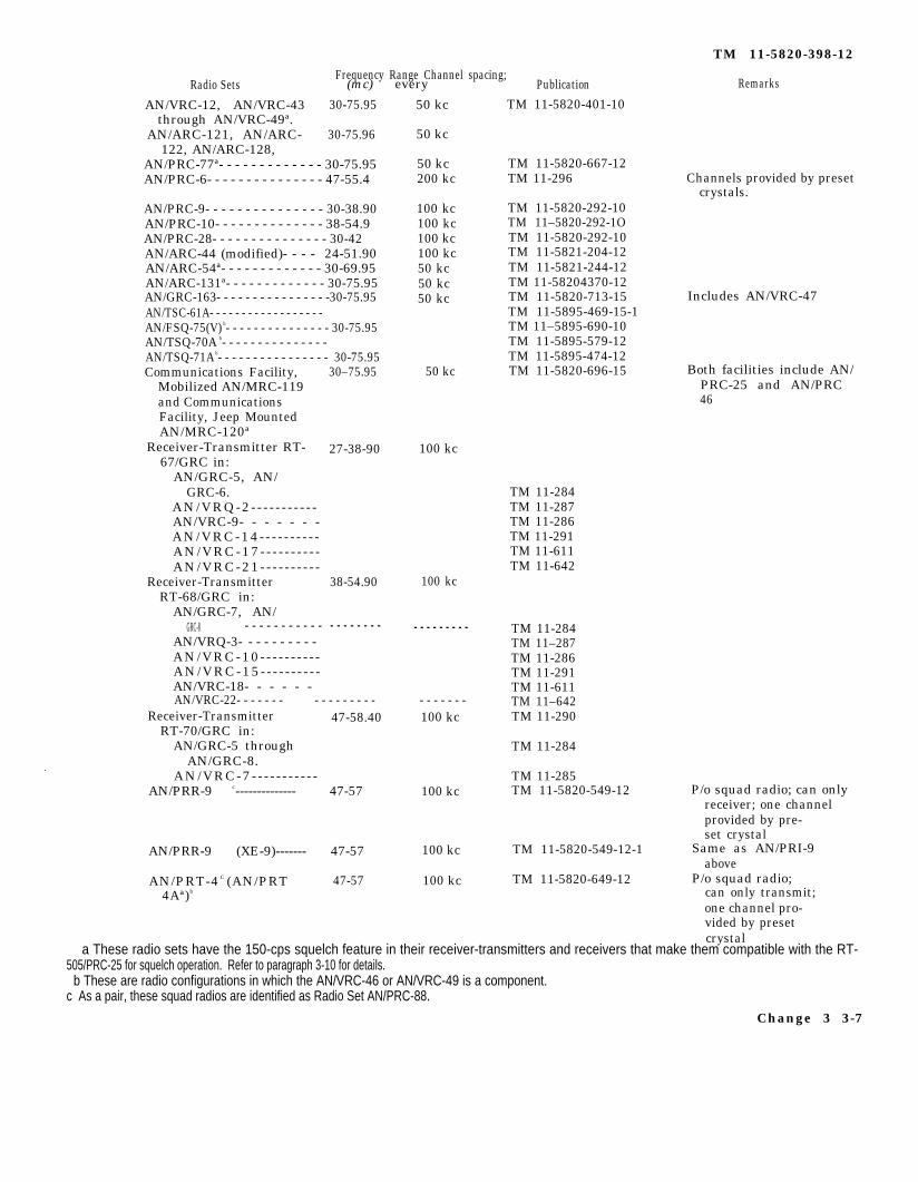
3-11. System Application
Figure 3-3 shows various frequency-modulated(FM) radio sets with which the RT-505/PRC25 can communicate within the 30-75.95-mega-cycle (mc) band. The chart below l ists thefrequency ranges, the channel spacing of theradio sets, and their associated publications.All radios listed, except those in which presetcrystals are required, can tune to any frequencywithin its operating range, Take note of thechannel spacing in kilocycles. For example,communication with the Radio Set AN/PRC-6 can occur on 50.00 mc, 50.20 mc, 50.40 mc,etc.
AN/PRC-25ª - - - - - - - - - - - - - - - - - - - - - - - - - - - - - - - - - - - -
Frequency Range Radio Sets - Publkd.km R4nmrks
50 kc TM 11-5820-398-12AN/VRC-53, AN/VRC-64, 30-75.95 50 kc TM 11-5820-498-12
AN/GRC-125, AN/GRC-160.ªAN/VRC-54ª- - - - - - - - - - - - - - - - - - - -30-75.95 50 kc Includes AN/VRC-46,
AN/PRC-25, andAN/VRC-24.
3 - 6
Frequency Range Channel spacing;Radio Sets (mc) every
AN/VRC-12, AN/VRC-43 30-75.95through AN/VRC-49ª.
AN/ARC-121, AN/ARC- 30-75.96122, AN/ARC-128,
AN/PRC-77ª- - - - - - - - - - - - - 30-75.95AN/PRC-6- - - - - - - - - - - - - - - 47-55.4
AN/PRC-9- - - - - - - - - - - - - - - 30-38.90AN/PRC-10- - - - - - - - - - - - - - 38-54.9AN/PRC-28- - - - - - - - - - - - - - - 30-42AN/ARC-44 (modified)- - - - 24-51.90AN/ARC-54ª- - - - - - - - - - - - - 30-69.95AN/ARC-131ª- - - - - - - - - - - - - 30-75.95AN/GRC-163- - - - - - - - - - - - - - - -30-75.95AN/TSC-61A- - - - - - - - - - - - - - - - - - AN/FSQ-75(V) b- - - - - - - - - - - - - - - 30-75.95AN/TSQ-70A b- - - - - - - - - - - - - - - AN/TSQ-71A b- - - - - - - - - - - - - - - - 30-75.95Communications Facility, 30–75.95
Mobilized AN/MRC-119and CommunicationsFacility, Jeep MountedAN/MRC-120ª
Receiver-Transmitter RT- 27-38-9067/GRC in:
AN/GRC-5, AN/GRC-6.
AN/VRQ-2 - - - - - - - - - - -AN/VRC-9- - - - - - -AN/VRC-14 - - - - - - - - - -AN/VRC-17 - - - - - - - - - -AN/VRC-21 - - - - - - - - - -
Receiver-Transmitter 38-54.90RT-68/GRC in:
AN/GRC-7, AN/
50 kc
50 kc
50 kc200 kc
100 kc100 kc100 kc100 kc50 kc50 kc50 kc
50 kc
100 kc
100 kc
GRC-8 AN/VRQ-3- - - - - - - - - - AN/VRC-10 - - - - - - - - - -AN/VRC-15 - - - - - - - - - -AN/VRC-18- - - - - - AN/VRC-22- - - - - - - - - - - - - - - - - - - - - - -
Receiver-Transmitter 47-58.40 100 kcRT-70/GRC in:
AN/GRC-5 throughAN/GRC-8.
AN/VRC-7 - - - - - - - - - - -AN/PRR-9 c-------------- 47-57 100 kc
- - - - - - - - - - - - - - - - - - - - - - - - - - - -
AN/PRR-9 (XE-9)------- 47-57 100 kc
AN/PRT-4 C (AN/PRT 47-57 100 kc4Aª)b
PublicationTM 11-5820-401-10
TM 11-5820-667-12TM 11-296
TM 11-5820-292-10TM 11–5820-292-1OTM 11-5820-292-10TM 11-5821-204-12TM 11-5821-244-12TM 11-58204370-12TM 11-5820-713-15TM 11-5895-469-15-1TM 11–5895-690-10TM 11-5895-579-12TM 11-5895-474-12TM 11-5820-696-15
TM 11-284TM 11-287TM 11-286TM 11-291TM 11-611TM 11-642
TM 11-284TM 11–287TM 11-286TM 11-291TM 11-611TM 11–642TM 11-290
TM 11-284
TM 11-285TM 11-5820-549-12
TM 11-5820-549-12-1
TM 11-5820-649-12
TM 11-5820-398-12
Remarks
Channels provided by presetcrystals.
Includes AN/VRC-47
Both facilities include AN/PRC-25 and AN/PRC46
P/o squad radio; can onlyreceiver; one channelprovided by pre-set crystal
Same as AN/PRI-9above
P/o squad radio;can only transmit;one channel pro-vided by presetcrystal
a These radio sets have the 150-cps squelch feature in their receiver-transmitters and receivers that make them compatible with the RT- 505/PRC-25 for squelch operation. Refer to paragraph 3-10 for details. b These are radio configurations in which the AN/VRC-46 or AN/VRC-49 is a component. c As a pair, these squad radios are identified as Radio Set AN/PRC-88.
Change 3 3-7

Figure 3-3.
TM
11-5820-398-12
3-8 C
ha
ng
e 3

CHAPTER 4
OPERATOR’S MAINTENANCE
TM 1 1 - 5 8 2 0 - 3 9 8 - 1 2
INSTRUCTIONS
Section 1. PREVENTIVE MAINTENANCE
4-1. Scope of Operator’s Maintenance
No special tools or test equipment are requiredfor operator’s maintenance of the AN/PRC-25Trichloroethane (item 1, app F) is required forcleaning (para 4-3). Operator’s maintenanceincludes the following:
a. Preventive maintenance (para 4-2, table4 - 1 ) .
b. Replacing the battery (para 2-4).c. Troubleshooting ( para 4-4 and 45).
4-2. Preventive Maintenance, General
Preventive maintenance is the systematic care,servicing, and inspection of equipment to pre-vent occurrence of trouble, to reduce downtime,and to assure that the equipment is service-able. Preventive maintenance checks and ser-vices (PMCS) defines procedures to be per-formed at specific intervals and under certainconditions (table 4-1 ).
a. Before you operate perform your before(B) PMCS.
b. While you operate, perform your during
(D) PMCS. The recording and reporting ofyour during (D) PMCS is done while perform-ing the after (A) PMCS.
c. After you operate, perform your after(A) PMCS.
d. If the equipment was not used during aweek, perform the (B) , (D) , and (A) PMCStogether with the weekly (W) PMCS.
e. I f the equipment fai ls to operate, trytroubleshooting (para 4-4 and 4-5) , I f theequipment still fails to operate, submit it tohigher maintenance for repair using the properforms (TM 38-750) .
f. The Item No. in table 4-1 shall be usedas a source of i tem numbers for the T MNumber column on DA Form 2404 (EquipmentInspection and Maintenance Worksheet) inrecording the results of the PMCS.
g. If the equipment must be kept in constantoperation, check and service only those itemsthat can be checked and serviced without dis-turbing operation. Make the complete checksand services when the equipment can be shutdown.
Change 5 4-1

TM 11-5820-398-12
Table 4-l. Operator’s/Crew Preventive Maintenance Checks and ServicesNOTE
Within the designated interval, these checks are to be performed in the order listed.
B- BEFOREOPERATION
ITEMNo. B D A
1
2
3
INTERVAL
e.
0
w
D- DURING A- AFTER W- WEEKLYOPERATION OPERATION
ITEM TO BEINSPECTED
Completeness
Operation
Battery
PROCEDURESCHECK AND HAVE REPAIREDOR ADJuSTED AS NECESSARY
All components are on hand to make theradio operation (appx B) ; that is tocommunicate.
While operating the radio, check thefollowing features:
Switches and controls (1) and (2)are not loose in their shafts.
VOLUME control ( 1 ) does not bindand there is no interruption ofreceived signal as control isrotated through its range .
\
2
Squelch operation is satisfactory(para 3-10), if used.
Communications is not intermittent.
Under normal conditions (basedon experience with antenna beingused, terrain, distance to otherradios , assigned operating frequen-cies, etc. ) , communication can beconducted.
Remove battery (para 2-4) i f radioset will not be used again thatday or longer.
Check to see that the battery case(1 ) is not swollen [bulging] , orleaking, and that the contactreceptacle (2) is not damaged.
FOR READINESS REPORT-ING EQUIPMENT IS NOT READY/AVAILABLE IF:
Operational compo-nent(s) is (are)not available.
Communication can-not be conductedunder normal con-ditions.
4-2 Change 5

TM 11-5820-398-12
Table 4-l. Operator’s/Crew Preventive Maintenance Checks and Services - Continued.
NOTEWithin the designated interval, these checks are to be performed in the order listed.
B- BEFORE D- DURING A- A F T E R W- WEEKLYOPERATlON O P E R A T I O N OPERATION
Change 5 4-3

TM 11-5820-398-12
Table 4-l. Operator’s/Crev Preventive Maintenance Checks and Services - Continued.NOTE
Within the designated interval, these checks arc to be performed in the order listed.
B- BEFORE D- DURING A- AFTER W- WEEKLYOPERATION OPERATION OPERATION
4-4 Change 5

TM 11-5820-398-12
4 - 3 . Cleaning
The surface of the equipment should beclean; that is, there should be no dirt, grease,oil or fungus on the surfaces.
WARNING
Fumes of TRICHLOROTRIFLUOROETHANE arepoisonous. Provide adequate ventilation wheneveryou use TRICHLOROTRIFLUOROETHANE. Donot use solvent near heat or open flame. TRICHLO-ROTRIFLUOROETHANE will not burn, but heatchanges the gas into poisonous, irritating fumes.DO NOT breathe the fumes or vapors. TRICHLO-ROTRIFLUOROETHANE dissolves natural skinoils. DO NOT get the solvent on your skin. Usegloves, sleeves, and an apron which the solventcannot penetrate. If the solvent is taken internally,consult a physician immediately.
a. Remove dust and dirt with a clean cloth.If dirt is difficult to remove, dampen the clothwith water; soap may be used for more effectivecleaning.
b. Remove grease, oil, fungus, and ground-indirt with a cloth dampened (not wet) witht r i c h l o r o t r i f l u o r o e t h a n e .
c. Clean the canvas items (CW-503/PRC-25and ST-138/PRC-25 (fig. 2-3)) with a brushmois tened w i th t r i ch l o ro t r i f luoroe thane .
d. Clean the contacts of the RT-841/PRC-77 AUDIO connector (fig. 3-1) and the handsetconnector (fig. 1-4) with a pencil eraser.
Section Il. TROUBLESHOOTING
4-4. Visual Inspection
a. When the equipment fails in communica-tion check the following items:
(1) Switches and controls are set cor-rectly (para 3-4).
(2) The handset and antenna are securedto the receiver-transmitter.
b. If the above procedures do not clear thetrouble, proceed to the troubleshooting chart(para 4-5).
4-5. Troubleshooting
The fol lowing chart contains procedures anoperator can do to try to restore communica-tion. Any trouble or defective equipment thatcannot be corrected by the operator shall bereferred to organizational maintenance (DAPam 738-750).
CAUTION
Do not move the MC and KC tuningcontrols while the radio is keyed.
Malfunction Probable Cause Corrective Action
1.
2.
Rushing noise is not a. POWER connector a. Tighten POWER connector.heard when function (item 13, fig. 5-2) is notswitch is set to ON. tightened.
b. Defective battery (fig. b. Perform the following:2-2). (1)
Rushing noise does notstop when functionswitch is set toSQUELCH.
(2)
(3)I
Set function switch to LITE; the dial lamp shouldlight.Key the receiver-transmitter and talk sidetoneshould be heard.If neither of dove indications is obtained, replacethe battery (Para 2-4) and repeat (1) and (2)above.
Defective receiver-trans- Rotate MC and KC controls back and forth a few times.mitter.
Change 6 4-5

TM 11-5820-398-12
Malfunction
3. Communication cannotbe conducted with dis-tant terminal on as-signed frequency; side-tone is heard ontransmission.
4. Unable to communicatein squelch mode (para 3-4g (function switch inSQUELCH position).
5. Reception satisfactory;on transmission, motor-boating is heard.
Probable Cause
a. Defective receiver-transmitter.
b. Radio is located in poor
c.
d.
e.
location.The antenna is loose inits receptacle.The distance to the nextradio terminal is toogreat for the short 3-foot Antenna AT-892/PRC-25 (fig. 1-2).Defective handset.
a. Distant radio is not
b.
c.
compatible.
Distant radio is compat-ible for squelch mode op-eration.
Radio is located in poorlocation.
Defective battery.
Corrective action
a.
b.
c.
d.
e.
a.
b.
c.
Perform the following:(1) Rotate the MC and KC controls back and forth a
few times,(2) Try alternate frequencies.
Move to another location; even a few feet may help. Setthe antenna vertical.Screw the antenna down fully.
Install the 10foot Antenna AT-271A/PRC (para 2-6b).
Perform the following(1) Use the other AUDIO connector.(2) Clean the connector contacts (para 4-3d) of both
the handset connector and the AUDIO connectors.If radio with which you are trying to communicate insquelch mode is not one of those identified in footnote aof the radios listed in paragraph 3-11, you must com-municate without squelch by setting the function switchto ON.If the distant radio is using RT-246/VRC or RT-524/VRC,its SQUELCH switch can be set in any position exceptOLD ON. If another radio, the 150 cps squelch tonemust be switched on.Move to another location; even a few feet may help.
Replace battery (para 2-4).
4 - 6 Change 5

Step Action
11 Adjust a nearby radio(known to be good) toreceive test signalstransmitted by RT-505/PRC-25. Set functionswitch of nearby radio atSQUELCH. Press push-to-talk switch of handsetconnected to RT-505/PRC-25 and send longvoice test signal.
12 Set function switch toOFF.
TM 11–5820-398-12
Normal indication Corrective measures
Test signal is heard loud and clear Higher category repair is required.at nearby radio; side tone is If motorboating is heard on transmission,heard in handset, replace battery.
Radio stops operating. Higher category repair is required.
5-7. Use of Test Sets, Radio FrequencyPower AN/URM-182 and TS-2609/U
The AN/URM-182 consists of Test Set, RadioFrequency Power TS-2609A/U and Cable As-sembly RF CG-409G/U stowed in Case, Test SetCY-6785/U. The TS-2609/U is a single unit. (TS-2609(•)/U, is used to identify both units.) TheTS–2609(•)/U is a small, 50-ohm impedance,throughline, rf wattmeter that measures for-ward and reflected rf power, transmitting inthe 30- to 70-mc range up to 100 watts. It haslittle effect on received rf power. To use the TS-2609(•)/U, proceed as follows.
a. Since the TS-2609(•)IU is connected be-tween the coaxial ANT connector and a 50-ohmantenna system or dummy load (not the whipantenna receptacle of the RT-505/PRC-25), thetest would only indicate whether the RT-505/PRC-25 has sufficient or insufficient output rfpower. If insufficient transmitting power isobtained (b(3) below), communication failurecould be attributed to one of the following:Whip antenna defective or not fully screwedinto the receptacle; weak battery; defectivehandset; or defective modulation or demodula-tion circuits in the radio.
b. Since the TS-2609(•)/U cannot be connectedto the whip antenna connector, use a vehicularwhip antenna system of another radio set, such
as the AS-1729/VRC (or AT-912/VRC) of theAN/VRC-12 radio series (TM 11-5820401-10-1,TM 11-5820401-10-2, or TM 11-5820401-12),or of Radio Sets AN/VRC-53, AN/VRC-64, AN/GRC-125, AN/GRC-160 (TM 11-5820-498-12). Toperform the test, proceed as follows. Refer toTM 11-6625-1686-15 for instructions on connec-tions and operation of the TS-2609/U and toTM ll-6625-2718-14&P for the TS-2609A/U ofthe AN/URM-182.
CAUTIONN e v e r c h a n g e f r e q u e n c i e s o f t h eBAND switch while the transmitter iskeyed (by pressing the handset push-to-talk switch). To do so damages mod-ules in the radio or may cause thewrong frequency to be set up for trans-mission.
(1) Leave the battery in the RT-505/PRC-25 and connect the TS-2609(•)/U between theRT-505/PRC-25 and the vehicular antenna sys-tem.
(2) Key the RT-505/PRC-25 at the fre-quency at which communication fails and atother frequencies in both bands.
(3) Normally forward power indicationsshould range between 0.5 and 3 watts, depend-ing on frequency.
Change 5 5-5
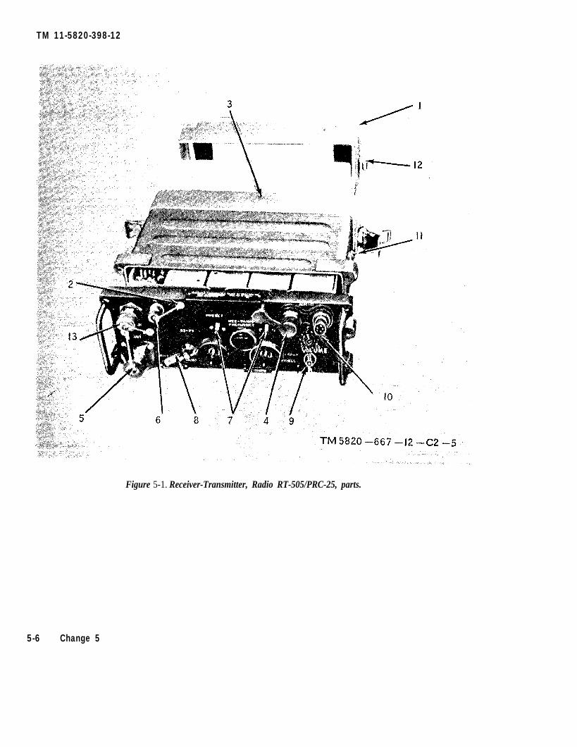
TM 11-5820-398-12
Figure 5-1. Receiver-Transmitter, Radio RT-505/PRC-25, parts.
5-6 Change 5

TM 11-5820-398-12
CHAPTER 5
ORGANIZATIONAL MAINTENANCE
Section 1. GENERAL
5-1. Scope of Organization Maintenance a. Multimeter AN/URM-105.
Organizational maintenance includes preven- b. Tool Kit, Electronic Equipment TK-101/G.
tive maintenance (para 5-3 and table 4-1) and c. Trichlorotrifluoroethane (item 2, app F).d. Silicone Compound (item 2, app F). 1
troubleshooting (para 5-4, 5-5, and 5-6).e. Graphite Grease, nonseizing compound
5-2. Tools, Materials, and Test Equipment (item 3, app F).
Required f. Epoxy (item 4, app F).g. Cleaning cloth.
Section Il. PREVENTIVE MAINTENANCE
5-3. Organizational PreventiveMaintenance Checks and Services
(PMCS)
Preventive maintenance is the systematic care,inspection, and servicing of equipment to main-tain it in serviceable condition, prevent break-downs, and assure maximum operational capa-bility. Organizational preventive maintenancechecks and services (PMCS) are performedquarterly.
a. Quarterly PMCS on the equipment will be
scheduled in accordance with the proceduresspecified in DA-Pam738-750,and performed as indi- 1cated in table 5-1.
b. The Item No. in table 5–1 shall be used asa source of item numbers for the TM numbercolumn on DA Form 2404 (Equipment Inspec-tion and Maintenance Worksheet) in recordingthe results of the PMCS.
c. If the equipment fails to meet the criteriain the Procedures column of the table, reportthe failure in accordance with the proceduresspecified in DA Pam 738-750. 1
Table 5-1. Organizational Preventive Maintenance Checks and Services-Quarterly Schedule
ItemNo.
1
2
3
Item to beinspected
Completeness
Publications
Modifications
ProcedureCheck for and have repaired or adjusted
as necessary
Check to see that all AN/PRC-25 components are on hand(app 11) or are amounted for (being repaired and/or I
on requisition).TM 11-5820-398-12 and TM 11-5820-398-20P are on hand
with latest changes; see DA Pam 25-30 current listing, I
Check DA Pam 25-30 to see if any modification work orders(MWO’S) are fisted against the AN/PRC-25 or its compo- Inents. ALL URGENT MWO'S must be applied within theperiod specified; all NORMAL MWO'S must be scheduled.
Change 6 5-1

TM 11-5820-398-12
ItemNo
4
5
6
Table 5-1. Organizational Preventive Maintenance Checks and Services-_Quarterly Schedule-Continued
Item to beinspected
Metal surfaces
Handset
RT-505/PRC-25(fig. 3-2)
ProcedureCheck for and have repaired or adjusted
as necessary
Remove fungus, rust and corrosion. Spot paint baremetal spots. Refer to SB 11-573 and TB 43-0118 forpainting instructions.
a. The O-ring in the cable connector is not loose ormissing.
b. Apply a thin coating of silicone compound (item 2,app F) to the O-ring (not to the connector con-tacts).
a. The clamps are not damaged and hold the CY-2562/PRC-25 securely to the radio case.
b. The pressure test screw is in place and epoxy (item4, app F) is applied over the edge of the screw.
c. Observe the case to see if there is any evidence ofbulging (due possibly to gas exploding inside thecase (para 1-8c).
d. Check the following front panel parts (fig. 5-2):(1) Electrical connector covers (4, 5, and 6) are
attached to the front panel and each cover fitssecurely on its connector.
(2) The dial locks (7) function to lock and release theMC and KC controls (fig. 3-1).
e. Clean out the whip antenna receptacle in the an-tenna mount (fig. 3-1). Clean out the small drainhole near the base of this antenna mount leadingto the threaded antenna receptacle.
f. Loosen the front panel captive screws (fig. 2-2),separate the front panel and chassis from thecase, and perform the following checks:
(1) Using lung power, blow out all parts on bothsides of the case (to get rid of gasses that mayhave accumulated).
(2) Inspect the battery connector for the following(a) A rubber gasket (shaped similarly to the metal
ring around the battery connector hole RT-505/PRC-25 case) must be installed on theradio connector. It must be undamaged, beseated flush with the bottom of the connec-tor (inside the four connector mountingscrews), and flush with the body of theconnector.
(b) The two O-rings on the radio connector mustbe installed and undamaged; that is, theymust not be sheared, and each O-ring mustbe seated, under tension, in its groove.
(c) The three radio connector pins are not bent orloose, or otherwise damaged. Put siliconecompound around the connector pins in therear of the connector. Use RTV102, or equiv-alent.
(d) Reinstall the chassis in the case; tighten thethree captive screws. There should be no gapor space between the edges of the case andthe front panel chassis.
5-2 Change 6

ItemNo.
7
8
9
10
11
TM 11–5820-398-12
Table 5-1. Organizational Preventive Maintenance Checks and Services-Quarterly Schedule-Continued
Item to beinspected
CY-2562/PRC-25(fig. 2-2)
AT-892/PRC-25(fig. 1-2)
AB-591A/PRC(fig. 1-2)
AT-271/PRC(fig. 1-2)
ST-138/PRC-25(fig. 1-2)
5-4. Visual Inspection
ProcedureCheck for and have repaired or adjusted
as necessary
a. Tighten the pressure relief valve, which must beinstalled (para 1-8C).
b. Apply a light pressure of air to both sides of thepressure relief valve; air should not go throughthe valve when applied from the outside of thecase and should when applied from inside thecase.
c. Clean out the CY-2562/PRC-25 (para 4-3).a. The bottom section holds the upper section firmly
in position when the upper section is bent atvarious angles.
b. Apply a thin coat of graphite grease (item 3, app F)to the threaded connector.
a. The unit is not damaged or distorted.b. Clean out the threaded receptacle and apply a thin
coat of graphite grease (item 3, app F) to thethreads on both ends of the unit.
a. The wire running through the sections is not bro-ken. There is no water in the sections.
b. When fully extended and assembled, each sectionfits into the next section.
c. The tip cap is in place.d. The threaded connector is securely attached to the
bottom section.e. Apply a thin coat of graphite grease (item 3, app F)
to the threaded connectors.a. All metal parts are secured to the convas assembly.b. Canvas areas are not torn and all straps are
attached to the canvas assembly.
Section III. TROUBLESHOOTING
a. When equipment failure occurs, inspect theequipment carefully for obvious defects. Thisprocedure may avoid further damage. Performthe following checks:
(1) Switches and controls are set correctly(para 3-4).
(2) The handset is seated in its connectorand the antenna is screwed down completely.
(3) The battery is properly connected to theradio connector (fig. 2-2). Check the battery bysubstitution,
b. If above visual checks do not reveal acause for radio failure, proceed to the equip-ment performance checks (para 5-5).
S-5. Equipment Performance Checklist
a. General. Check the performance of theequipment as outlined in the following check-list, Start at the beginning and follow each stepin the order given. If suggested correctivemeasures do not clear the trouble, submit theequipment to higher maintenance category forrepair; note on the repair tag the fault and thecorrective measures taken.
5-6. Repair and Replacement Parts
For AN/PRC-25 repair parts and replacementparts, refer to TM 11-5820-398-20P. For RT-505/PRC-25 parts, refer to TM 11-5820-497-20P.
Change 5 5-3

TM 11-5820-398-12
b. Check list.
Step Action1
2
34
5
6
7
8
9
Install desired antenna inantenna mount.
Connect handset to eitherAUDIO connector.
Set VOLUME control to 5.Set function switch to
LIFE,Set function switch to ON.
Set function switch toSQUELCH.
Set up a nearby radio(known to be good) totransmit on authorizedchannel in low (30- to 52-mc) band (if possible),and tune RT-505/PRC25to this channel. Obtain along voice test signalfrom nearby radio.
Adjust a nearby radio totransmit on authorizedchannel in high (53-75mc) band (if possible),and tune RT–505/PRC25to this channel. Obtainlong voice test signalfrom nearby radio,
Adjust a nearby radio totransmit on channelslisted below (ifauthorized). Obtain longvoice test signal on eachchannel. Tune RT–505/PRC-25 to each channelin order given below:
30.00 mc30.05 mc30.10 mc30.20 mc30.30 mc30.40 mc30.50 mc30.60 mc30.70 mc30.80 mc30.90 mc
10 Adjust a nearby radio(known to be good) toreceive test signalstransmitted by RT-505/PRC-25. Press push-to-talk switch of handsetconnected to RT-505/PRC-25 and send longvoice test signal.
5-4 Change 5
Normal indication
Channel dial lights.
Rushing noise is heard in handsetwhen no signal is received.
Rushing noise is not heard inhandset.
Test signal is received and heardloud and clear.
Test signal is heard loud andclear.
Test signal is heard loud and clearon each channel.
Corrective measures
Replace BA-4386/U.
a. Connect handset to other AUDIOconnector.
b. Check handset by substitution.c. Replace battery.Higher category repair is required.
If received test signal is weak, checkantenna and antenna connection.
Higher category repair is required.
Record channels not received. Highercategory repair is required.
Test signal is heard loud and clear a. Check handset by substitution. If signalat nearby radio; sidetone is cannot be received at all, higherheard in Handset. category repair is required.
b. Tune nearby radio to several channels onboth sides of operating channel. Ifsignal is received off channel, highercategory repair is required.

TM 1 1 - 5 8 2 0 - 3 9 8 - 1 2
CHAPTER 6
MATERIEL USED IN CONJUNCTION WITH RADIO SET
A N / P R C - 2 5
6-1. Radio Relay Procedures and Retrans-m i s s i o n C a b l e K i t MK - 4 5 6 ( * ) G R C a
With Cable Assembly, Special Purpose, Elec-trical CX-4656/GRC from Retransmission Ca-b l e K i t MK-456 /GRC ( f i g . 6 -1 ) , two com-patible FM radios may be used as a radio re-lay for other radio sets that are too far distantto communicate directly with each other. Theradio relay can be accomplished by intercon-necting the radios l isted in paragraph 3-1Oc(1) through (3) with the CX-4656/GRCas shown in figure 6-2.
a . M K - 4 5 6 ( * ) / G R C . T h e k i t6-l and 6-1.1) consists of Bag, Cotton DuckCW-502/PRC and 50-foot cable assembly CX-4656/GRC. The network box has an audioconnector to which a handset or audio acces-sory is attached to monitor ( l isten to) thesignals being retransmitted in one direction.
b. Selection of Frequencies( 1 ) I n t e r f e r e n c e p r o b l e m s . W h e n f r e -
quencies that are to be used for retransmissionare planned, the two frequencies must be atleast 3 mc apart and must be selected so thatthe transmitter of neither radio will interferewith the receiver of the other, as shown in theretransmission interference chart (fig. 7–1 ),
( 2 ) U s e o f i n t e r f e r e n c e c h a r t . E a c hsquare on the retransmission interference chart(fig. 7-1) represents the intersection of twofrequencies. The transmitter frequency is inmc and is plotted from left to right; the re-ceiver frequency is in mc and is plotted frombottom to top. The black areas represent fre-quencies at which interference will occur; thewhite areas represent frequencies at whichinterference wil l not occur. There are f ivechannels per square of the chart. Examples of
use of the chart are given in (a) and (b) be-low.
(a) A transmitter frequency of 54 mcwill not interfere with a receiver frequency of32 mc.
(b) A transmitter frequency of 54 mcwil l interfere with a receiver frequency of31 mc.
Note. Trial and error checks may disclose thatfrequencies other than those given in the chart (fig.7-1) are interfering frequencies. Record these fre-quencies for future use.
c. Retransmission Requirements.. Figure 6-2 shows the connections between an AN/PRC26 (radio set No. 2) and another radio set atthe relay site. The chart in figure 6-2 showsthe settings of the squelch-functioning switch-es required at the various sets in the radionet. In general, the relay site radios mustoperate with squelch signals being receivedf rom the d i s tant rad ios ( rad io se t s No .1 and No. 4) . Refer to paragraph 3-10c(1)through (3) and f igure 3-3 for FM radiosthat can communicate with each other in aradio net.
d. System Lineup. Refer to figure 6-2 forthe discussion in (1) through (9) below.
(1) Set up each radio at the relay site andat the distant radio sets to operate w i t h o u tsquelch.
(2) Set the operating frequency of radiosets No. 1 and No. 2 on the same frequency,F1. Set the operating frequency of radio setsNo. 3 and No. 4 on another frequency, F2(b above) .
(3) Establish communication between ra-dio sets No. 1 and No. 2 and between radiosets No. 3 and No, 4.
aMK-456(*) /GRC represents MK-456/GRC and MK-456A/GRC. TM 11-5995-202-15c o n t a i n s o p e r a t i n g a n d m a i n t e n a n c e i n f o r m a t i o n f o r t h e k i t . T h e M K - 4 5 6A / G R Cincludes CW-502/GRC and CX-4656A/GRC; the MK-456/GRC includes CW-502/GRc andCX-4656/GRC. All references to MK-456/GRC and CX-4656/GRC apply also toMK-456A/GRC and CX-4656A/GRC.
Change 3 6 - 1

TM 11-5820-398-12
Figure 6-1. Retransmission Cable Kit MK-456A/GRC.
(4) When communication is satisfactorilyestablished between the associated radio sets,adjust each radio to operate on squelch (seechart, fig. 6-2). Check for satisfactory com-munication on squelch operation between theassociated pairs of radio sets (No. 1 and No.2; No. 3 and No. 4).
(5) When operation on squelch betweenthe radio sets is satisfactory, advise the radiooperators at radio sets No. 1 and No. 4 tostandby while the following arrangements arebeing made:
(a) When the RT-505/PRC-25 at the re-lay site is connected in retransmission to anoth-e r R T - 5 0 5 / P R C - 2 5 o r a n R T - 8 4 1 / P R C - 7 7 ,
connect the connectors on the ends of the CX-4656/GRC to an AUDIO connector on eachreceiver-transmitter. On each receiver-trans-mitter, set the function switch to RETRANS.
(b) When the RT-505/PRC-25 at the relaysite is connected for retransmission to the RT-2 4 6 / V R C o r R T - 5 2 4 / V R C o f t h e A N / V R C -12 radio series, connect one end of the CX-4656/GRC to an AUDIO connector of the
RT-505/PRC-25 and connect the other endof the CX–4656/GRC to the RETRANSMITR/W connec to r o f the R -246 /VRC or RT-524/VRC. Set the function switch of the RT-505/PRC–25 to RETRANS. Set the SQUELCH
6-2 Change 3

Figure 6-1.1.
TM
11-5
82
0-3
98
-12
Ch
an
ge
3 6-3

TM 11-5820-398-l2
switch of the RT-246/VRC or RT-524/VRCto NEW ON when the radio set with which itcommunicates is one of those given in para-graph 3 - 1 0C ( 1 ) t h r o u g h ( 4 ) ; set theSQUELCH switch to OLD ON for any otherrad io s e t
(6) Communicate with radio set No. 1from radio set No. 2, and advise the radio setNo. 1 operator that the relay site is preparedfor communication with radio set No. 4
(7) Communicate with radio set No. 4from radio set No. 3, and advise the radio setNo. 4 operator that the relay site is preparedfor communication with radio set No. L
(8) Communication proceeds automati -cally between radio sets No. 1 and No. 4 without any operation required at the relay site.
( 9 ) F o r t h e o p e r a t o r a t t h e r e l a ys i t e t o c ommunica te w i th rad io s e t No . 4c o n n e c t a h a n d s e t t o t h e a u d i o c o n n e c t o ri n t h e n e t w o r k b o x ( f i g . 6 - I a n d 6 - 1 . 1 ) .To c ommunica te w i th rad i o s e t No . l ,c o n n e c t t h e h a n d s e t t o r a d i o s e t N o . 2( w h i c h i s t h e o n e t h a t i s n e x t t o t h enetwork box ).
6-2. Battery, Dry BA-398/U for ArcticOperation( f ig , 6-3)
Battery, Dry BA-398/U is used in place of
Battery, Dry BA-386/PRC-25, BA-4386/U tos u p p l y p o w e r f o r t h e A N / P R C 2 5 d u r i n garctic operation. The BA-398/U consists ofbattery units within a carrying vest. CableAssembly, Special Purpose, Electrical CX-
8808/G is not issued as part of the BA-398/N; it is required to connect the BA-398/U tothe RT-50S/PRC25 POWER connector . Be-fore operation, the BA-398/U and vest mustbe warmed up at temperature above freezingfor approximately 8 hours. The average life ofthe BA-398/U under arctic conditions, whenused properly, is approximately 17 hours. SeeSB 11-576 (Apr 1969) for battery authorization,
6-3. Antenna Equipment RC-292
WARNING
Operators must be familiar with the requirements ofTB Sig 291 and the warnings in the front of thismanual. Failure to do so can result in DEATH shouldan antenna contact any power lines. I
Antenna Equipment RC-292 is an elevated,ground-plane antenna that may be used to ex-tend the operating distance of numerous ra-d i o s i n c l u d i n g t h e A N / P R C 2 5 w h e n i t i sused at a fixed location. The RC-292 is usedinstead of the antenna that is issued with theAN/PRC25 and is connected to the RF cableANT connector of the RT-505/PRC25 ( f ig .3-1). Installation instructions for the RC-292are contained in TM 11-5820-34%15. Opera-tion of the radio set is unchanged (para 3-2through 3-5) . The number of RC-292 ele-ments required for the vertical and ground-plane sections for a given frequency band areas given in the chart below.
6-4 Change 6

TM 11-5820-398-12
6-4. Antenna, Homing Loop AT-784/PRC PRC. Cap, Electrical CW-922/GRC, which isattached to the CG-3344/PRC, is used as a(fig. 6-4)
Antenna, Homing Loop AT-784/PRC is used grounding cap and must be connected to the
for detection and location of radio signal in 3- and 10-foot whip antenna connectors. The
the 30- to 76-mc range. It consists of the com- CW-922 /GRC i s used t o p revent poss ib l e
ponents shown in figure 6-4. Cable Assembly, radiofrequency radiation from this antenna
Radio Frequency CG-3344/PRC in for con- connector from interfering with the sensingnecting the radio set and Antenna AT-1082/ operation of the AT-1082/PRC. Cable Assem-
Change 6 6-4.1/(6-4.2 blank)


Figure 6-2.
C 2, T
M 11-5820-398-12
6-
5

C 2, TM 11-5820-398-12
Figure 6-3. Battery, Dry BA-398/U, with Cable Assembly, Special purpose,Electrical CX-8088/G.
i s c on -bly , Radio Frequency CG-2840A/Unected to the CG-3344/PRC to extend thedistance between the radio set and the AT-1082/PRC. Refer to TM 11–5985–284–15 foroperating instructions with radio sets such asthe AN/PRC-25.
6-5. Antenna AT-984/G, Installation andMaintenance(fig. 6-5)
Antenna AT-984A/G (FSN 5820-926-0201)is a long-wire, multiple wavelength antennathat is used to extend the normal transmissionand reception range of radio sets that are pro-
vided with the RT–505/PRC-25 and RT-841/PRC–77.
a. Description. The AT-984/G consists of acanvas bag and 150 feet of antenna wirewound on a reel. The antenna wire is connectedto the reel with a nylon cord (fig. 6-8). Acord at the other end of the wire is used tosuspend the antenna wire during operation ofthe radio set. The end of the antenna wire issoldered to a terminal lug that i s c r impedaround the wire and the insulating tubing tostrengthen the connection. The canvas bag hastwo locking devices on the rear for attachment to the belt of the user while he is unwindingthe antenna wire with the reel inside the bag.
6 - 6

C 2, TM 11-5820-398-12
Figure 6-4. Antenna Homing Loop AT-784/PRC.
Siting and Installation. line of sight. That is, if the location of the(1) S i t i n g ( f i g . 6 – 6 ) . T h e o p e r a t i n g other radio station can be seen, transmission
range of the AN/PRC-25 and is primari ly and reception will probably be satisfactory. An
6-7

C 2, TM 11-5820-398-12
intervening hill or tall building may hamperor prevent contact with the other station.
( a ) A v o i d s i t i n g t h e r a d i o s e t i nvalleys, densely wooded areas, and low places.Location on a hilltop will increase the opera-ing range if the other station’s location can beseen.
(b) Avoid s it ing the radio set nearinterference sources such as power ortelephone lines, radar sets, and field hospitals.
(c) Make sure that there are no ob-stacles preventing the antenna wire from be-ing extended its full length of 150 feet in astraight line toward the other station. Trans-mission and reception with a long-wire anten-na is off the end of the antenna in the direc-tion away from the radio set.
(2) Installation. The speed of the reelaction can be varied by changing the positionof the button on the side of the reel. With thebutton in one position, the reel turns slowlybecause the ratchet is engaged. With the but-ton on the other position, the reel turns freelybecause the’ ratchet is not engaged.
(a) Connect the terminal lug at the endof the antenna wire to the radio set as givenin 1 through 3 below. Figure 6–7 shows theconnection to the RT-505/PRC-25,
1 . Remove the long whip antenna
AT-271A /PRC f rom Suppor t , Antenna AB-591/PRC-25.
2. Unscrew the AB-591/PRC-25slightly, and insert the lug of the antennawire under it.
3.Tighten the AB-591/PRC25.
4 . W h e n t h e a n t e n n a i s a i m e dtoward the other radio station that is alsoequipped with a long-wire antenna, the areaof communication covers 18° of azimuth oneither side of the line along which the antennais aimed (B, fig. 6-6). If the other station isequipped only with a whip antenna, the areao f c o m m u n i c a t i o n c o v e r s o n l y 15° (A,fig. 6-6).
(b) Tie the cord that is attached to theantenna wire to a nearby support that is ca-pable of supporting the antenna wire when it is stretched to the other support 150 feetaway.
(c) Unreel the antenna wire by movingin the direction of the other radio station.
Note. The reel can be placed in the can-vas bag which then can be attached to the User'strouser belt. In this way, the antenna wire can be un-reeled without handling the reel.
(d) Stretch the antenna wire approxi-mately 4 feet above the ground by securing
6 - 8

TM 11-5820-398-12
Figure 6-6. AT-984A/G, radiation patterns and sitingdiagram.
the reel to a building, tree, post, or similarsupport. Use the cord that ties the antennawire to reel (fig. 6-8.)
WARNINGIf the tactical situation permits, usewarning signs or similar safety meas-ures to prevent personnel and vehiclesfrom running into the stretched an-tenna wire.
c. Maintenance. There are no maintenanceparts for the AT-984A/G.
(1) If the terminal lug is broken, damaged,or lost, cut off the rubber tubing immediatelybehind the terminal lug (fig. 6-8), and cut backthe tubing to expose 1/4 inch of antenna wire.
Obtain a new terminal lug crimp the terminallug around the tubing in the same manner asthe old terminal lug was crimped. Solder the 1/4inch of projecting antenna wire to the terminallug.
(2) If it is necessary to replace either of thetwo lengths of cord, obtain a 5-foot length ofnonconductive, 10-pound test, olive-drab cord.To prevent the nylon cord from unraveling, putthe end above a flame momentarily.
(3) No lubrication of the reel is required.
d . C l e a n i n g . U n r e e l t h e a n t e n n a w i r ea n d c l e a n i t w i t h a c l e a n c l o t h a n ds o l v e n t .
6-6. Loudspeaker, Electromagnetic LS-549/
PRC
This item is no longer available.
6-7. Radio Set Control Group AN/GRA-
39(•)
NOTERadio Set Control Group AN/GRA-39(•) represents all models of the equipment; Control, Radio Set C-2328(•)/GRA-39 represents all models of thee q u i p m e n t ; C o n t r o l , R a d i o S e t C -2329(•)/GRA-39 represents all modelsof the equipment.
The AN/GRA-39(•) may be used to provideremote radio control of radio transmission andreception of the AN/PRC-77 up to approxi-mately 2 miles (3.3 kilometers, approximately)(a below). This equipment may also be used toprovide radio/wire integration (RWI) betweenSwitchboard, Telephone SB-22/PT (switch-board) (TM 11-5805-262-12) and the AN/PRC77 (b below). Installation and operating instruc-tions for the AN/GRA-39(•) are provided in TM11-5820-477-12.
a. Remote Radio Control. Operation of theAN/PRC77 as described in paragraphs 3-2through 3-8 is unchanged, except as follows:
Change 6 6 - 9

TM 11-5820-398-12
Figure 6-7. Connection of antenna wire of AT-984AlG to RT-841/PRC-77.
(1) When the AN/GRA-39 or AN/GRA-39A scinded MWD) to permit use of the function
is used and its local control, the C-2329/GRA-39 switch on the RT-841./PRC77 in the SQUELCH
or C-2329A/GRA-39, has not been modified by position, the radio communication must be con-
the application of MWO 11-5820-477-30/1 (re- ducted with the function switch
6-10 Change 5
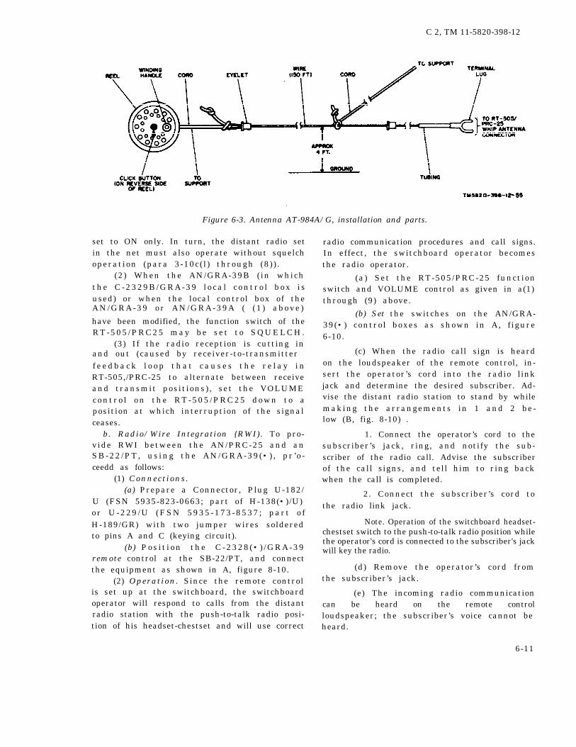
C 2, TM 11-5820-398-12
Figure 6-3. Antenna AT-984A/G, installation and parts.
and out (caused by receiver-to-transmitter
set to ON only. In turn, the distant radio setin the net must also operate without squelchoperation (para 3-10c( l ) through (8)) .
(2) When the AN/GRA-39B ( in whicht h e C - 2 3 2 9 B / G R A - 3 9 l o c a l c o n t r o l b o x i sused) or when the local control box of theAN/GRA-39 o r AN/GRA-39A ( ( 1 ) above )
have been modified, the function switch of theR T - 5 0 5 / P R C 2 5 m a y b e s e t t o S Q U E L C H .
(3) If the radio reception is cutting in
f e e d b a c k l o o p t h a t c a u s e s t h e r e l a y i nRT-505,/PRC-25 to alternate between receiveand transmit posit ions) , set the VOLUMEc o n t r o l o n t h e R T - 5 0 5 / P R C 2 5 d o w n t o aposition at which interruption of the signalceases.
b. Radio/Wire Integration {RWI). To pro-vide RWI between the AN/PRC-25 and anSB-22 /PT , us ing the AN/GRA-39 (• ) , p r ’ o -ceedd as follows:
(1) Connections.(a) Prepare a Connector, Plug U-182/
U (FSN 5935-823-0663; part of H-138(•)/U)or U-229 /U (FSN 5935 -173 -8537 ; par t o fH-189/GR) with two jumper wires solderedto pins A and C (keying circuit).
(b) Pos i t i on the C -2328 (• ) /GRA-39remote control at the SB-22/PT, and connectthe equipment as shown in A, figure 8-10.
(2) Operation. Since the remote controlis set up at the switchboard, the switchboardoperator will respond to calls from the distantradio station with the push-to-talk radio posi-tion of his headset-chestset and will use correct
radio communication procedures and call signs.In effect, the switchboard operator becomesthe radio operator.
(a) Set the RT-505/PRC-25 functionswitch and VOLUME control as given in a(1)through (9) above.
(b) Set the switches on the AN/GRA-39(•) control boxes as shown in A, f igure6-10.
(c) When the radio call sign is heardon the loudspeaker of the remote control, in-sert the operator’s cord into the radio linkjack and determine the desired subscriber. Ad-vise the distant radio station to stand by whilemaking the arrangements in 1 and 2 be-low (B, fig. 8-10) .
1. Connect the operator’s cord to thesubscriber’s jack, ring, and notify the sub-scriber of the radio call. Advise the subscriberof the call signs, and tell him to ring backwhen the call is completed.
2. Connect the subscriber’s cord tothe radio link jack.
Note. Operation of the switchboard headset-chestset switch to the push-to-talk radio position whilethe operator's cord is connected to the subscriber's jackwill key the radio.
(d) Remove the operator’s cord fromthe subscriber’s jack.
(e) The incoming radio communicationcan be heard on the remote controlloudspeaker; the subscriber’s voice cannot beheard.
6-11

TM 11-5820-398-12
(f) When the subscriber’s signal indicator 6-8 .shows white, insert the operator’s cord into thesubscriber’s jack and challenge the circuit with-
Radio Set Control AN/GSA-7 and
Oscillator, Audio Frequency 0-574/
GRAout operating the headset-chestset switch to thepurh-to-talk position. a. General.
(g) Remove the subscriber’s cord from the (1) Oscillator, Audio Frequency(figs. 6-11 through 6-13) produces aardio link jack.
Figure 6-9. Deleted.
O-574-GRA
6-12 Change 5

Figure 6-10.
TM
11-5820-398-12
Ch
an
ge
3
6
-13

TM 11-5820-398-12
1,600-cps ringing signal for transmissionthrough a radio system. The 0–574/GRA hastwo cable assemblies: Cable assembly (SC-C-75348) and Cable Assembly, Special Purpose,Electrical CX-10177/U. The cable assembly(SC-C-75348) is provided for connection be-tween the O-574/GRA and an audio accessorysuch as Handset H-33/PT; the CX–10177/Uis provided for connection between the 0–574/GRA and the RT-505/PRC–25 and an audioaccessory, such as Handset H–189/GR, combatvehicle crewman (CVC) helmet, etc.
NOTE
The O-574/GRA may be used with
other radio sets such as the AN/V R C - 1 2 s e r i e s ; t h e A N / P R C - 7 7 ,AN/VRC-53 , and Rad io Se t s AN/G R C - 3 t h r o u g h A N / G R C - 8 , e t c .The 0-574/GRA is provided to radiosets in an RWI network to enable theradio operator to ring into a switch-board which is connected to anotherradio set through Radio Set ControlAN/GSA-7 ( (2) below).
(2) Radio Set Control AN/GSA-7 (TM11-5135–115) provides RWI between Switch-board, Telephone SB-22/PT (TM 11-5805-262-12) and a radio set as far as 10 miles (16
km, approximately) distant from the radio set.
Figure 6-11. Oscillator. Audio Frequency 0-574/GRA..
6-14 Change 3
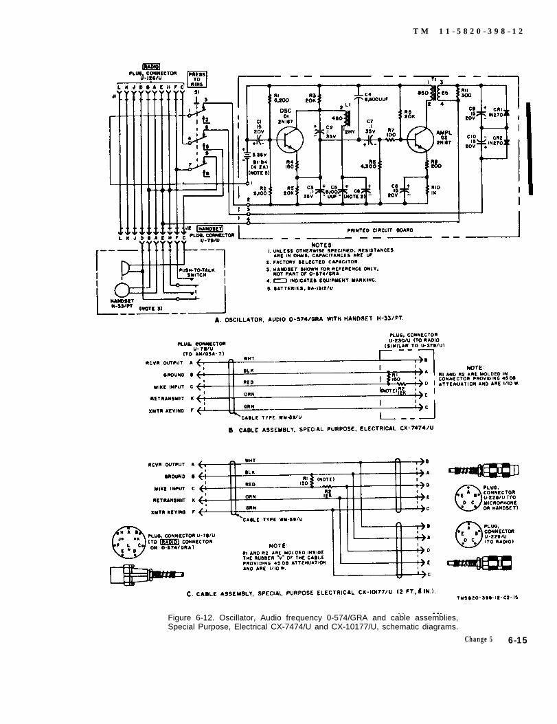
T M 1 1 - 5 8 2 0 - 3 9 8 - 1 2
Figure 6-12. Oscillator, Audio frequency 0-574/GRA and cable assemblies,Special Purpose, Electrical CX-7474/U and CX-10177/U, schematic diagrams.
Change 5 6-15

TM 11-5820-398-12
Figure 6-13. Oscillator, Audio Frequency 0-574/GRA with Batteries, DryBA-1312/U.
With the AN/GSA-7, there are four methodsof providing RWI, depending on the numbero f AN/GSA-7 ’ s in the sys tem ( f i g . 6 -15 ) .Cable Assembly, Special Purpose, ElectricalCX-7474/U ( f ig , 6-14) is required for con-nection between the receiver-transmitter of theradio set and the AN/GSA-7.
(a) W h e n t h e r e i s a n A N / G S A - 7 a tthe other radio station (A, fig. 6-15) or theother radio stat ion has an 0-574/GRA (C,f i g . 6 -15 ) , the AN/GSA-7 r ing ing f ea ture(converting the switchboard 20-cps ringingsignal to a 1,600-cps signal for trasmissionthrough the radio system and vice versa) canbe used. For this reason, a radio operator atthe AN/GSA-7 is not required as in the situa-tions in (b) below. The operating proceduresfor two AN/GSA-7’s in the system are givenin c below. The operating procedures for AN/
6-16
GSA–7 and O–574/GRA in the system aregiven in d below.
(b) W h e n t h e r e i s n o A N / G S A – 7 a tone radio station (B, D, fig. 6–15), the auto-m a t i c r i n g i n g f e a t u r e i n t h e A N / G S A - 7through the radio system is no longer effec-tive. Accordingly, either an operator is at theAN/GSA-7 to arrange with the switchboardoperator for RWI (B, fig. 6–15; d(l) below)or a telephone next to the radio and connectedto it through the switchboard is used by theswitchboard operator to hear radio calls (D,f i g . 6 -15 ) .
b. Connections. The following connectionsat the AN/GSA–7 are used whether there isa radio operator in the system (c below) or not(d below).
(1) Interconnect t h e A N / G S A - 7 a n dR T - 5 0 5 / P R C - 2 5 w i t h t h e C X - 7 4 7 4 / U ( A ,
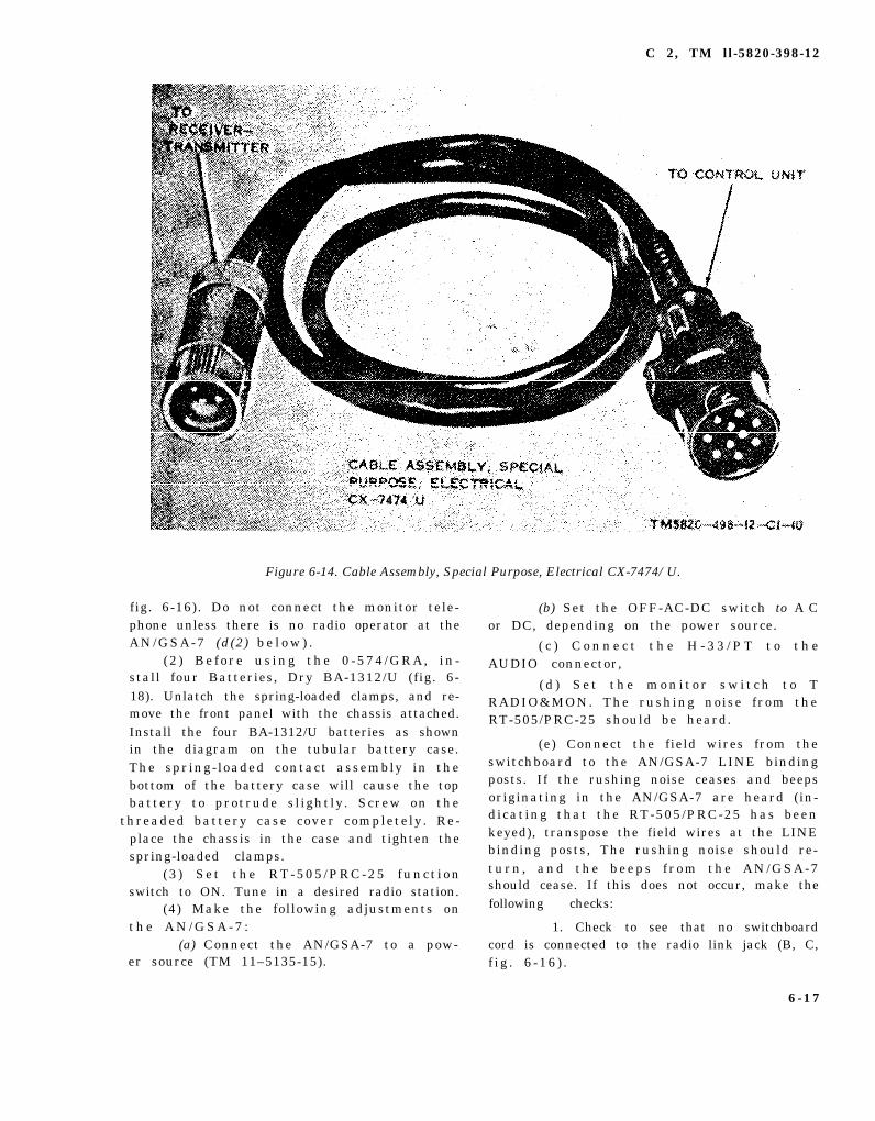
C 2, TM ll-5820-398-12
Figure 6-14. Cable Assembly, Special Purpose, Electrical CX-7474/U.
fig. 6-16). Do not connect the monitor tele-phone unless there is no radio operator at theAN/GSA-7 (d(2) b e l o w ) .
( 2 ) B e f o r e u s i n g t h e 0 - 5 7 4 / G R A , i n -stall four Batteries, Dry BA-1312/U (fig. 6-18). Unlatch the spring-loaded clamps, and re-move the front panel with the chassis attached.Install the four BA-1312/U batteries as shownin the diagram on the tubular battery case.The spring-loaded contact assembly in thebottom of the battery case will cause the topbattery to protrude sl ightly. Screw on the
threaded battery case cover completely. Re-place the chassis in the case and tighten thespring-loaded clamps.
(3 ) Se t the RT-505 /PRC-25 func t i onswitch to ON. Tune in a desired radio station.
(4) Make the following adjustments ont h e A N / G S A - 7 :
(a) Connect the AN/GSA-7 to a pow-er source (TM 11–5135-15).
(b) Set the OFF-AC-DC switch to A Cor DC, depending on the power source.
( c ) C o n n e c t t h e H - 3 3 / P T t o t h eAUDIO connector,
( d ) S e t t h e m o n i t o r s w i t c h t o TRADIO&MON. The rushing noise from theRT-505/PRC-25 should be heard.
(e) Connect the field wires from theswitchboard to the AN/GSA-7 LINE bindingposts. If the rushing noise ceases and beepsoriginating in the AN/GSA-7 are heard (in-dicating that the RT-505/PRC-25 has beenkeyed), transpose the field wires at the LINEbinding posts, The rushing noise should re-turn , and the beeps f r om the AN/GSA-7should cease. If this does not occur, make thefollowing checks:
1. Check to see that no switchboardcord is connected to the radio link jack (B, C,f i g . 6 -16 ) .
6-17

Figure 6-15.
C
2, T
M
11-5820-398-12
6-1
8

2. Check to see that the field wiresare not short-circuited.
(f) Proceed to check the operation ofthe the radio with the H-33/PT.
(g) Use the procedures in c be l owwhen there are two AN/GSA-7’s in the sys-tem, and those in d below when there is noother AN/GSA-7 in the system.
c. T w o A N / G S A - 7 ' s i n S y s t e m . W h e nthere is an AN/GSA-7 at each radio station,no radio operator is required at the AN/GSA-7 that is connected to the RT-505/PRC-25 (A,f ig . 6-15) . Normal r inging between switch-board operators over the radio system can beused.
(1) Interconnect the AN/GSA-7 equip-ment (b above).
(2) At each AN/GSA-7, set the monitorswitch to T RADIO&MON.
(8) Set the switch on each subscriber’stelephone to LB operation :
( 4 ) Swi t chboard and subscr iber t e l e -phone operation may now proceed normallyfor radio operation. Use the hand generator(20 cps) to call the distant switchboard; usepush-to-talk radio operation with the properradio call signs and radio procedures.
d. One AN/GSA-7 in System. When thereis no AN/GSA–7 at the other radio station,there are three methods of providing RW1. Inone arrangement ((1 ) below), a radio opera-tor is stationed at the AN/GSA-7, to makethe RWI arrangements with the switchboardoperator (B, fig. 6-15). In a second arrange-ment ((2) below), a telephone at the switch-board is continuously connected to the radiosystem; the switchboard operator answers ra-dio calls on this telephone and makes RWIconnections, becoming a radio operator for theoperation (D, fig. 6-15). In a third arrange-ment ( (3) below), the distant radio stationopera to r i s p rov ided w i th an 0 -574 /GRAwhich will provide the 1,600-cps signal to ringthrough an unattended AN/GSA-7 to call theswitchboard (C, fig. 6-15).
(1) Radio operator at AN/GSA-7. T h e s eprocedures require a radio operator at theA N / G S A - 7 .
(a) Interconnect the AN/GSA-7 equip-ment (b above).
(b) At the AN/GSA-7, set the moni-tor switch to T RADIO&MON position. Use
C 2, TM 11-5820-398-12
the H-33/PT to communicate with the distantradio station.
(c) When RWI is required for commu-nication with a switchboard subscriber, advisethe distant radio station to stand by while thearrangements in 1 through 3 below are beingmade:
1 . O n t h e A N / G S A - 7 , h o l d t h emonitor switch at R TEL to ring the switch-board, Release the switch, and request theswitchboard operator for connection with thedesired subscriber.
2. At the switchboard, the operatorconnects the operator’s cord to the desiredsubscriber’s jack, rings, advises the subscriberof the radio call, and the call signs, and re-quests him to ring back when the radio com-munication is completed.
3. The switchboard operator thenconnects the subscriber’s cord to the radio linkjack (B, fig. 6-16) and tells the radio opera-tor that the subscriber is ready.
(d) At the AN/GSA-7, the radio op-erator sets the AN/GSA-7 monitor switch toT R A D I O & M O N p o s i t i o n . C o m m u n i c a t i o nbetween the subscriber and the distant radiostation proceeds automatically on push-to-talkoperation. The radio operator at the AN/GSA-7 can monitor the communication.
(e) At the switchboard, the operatorremoves the operator ’s cord from the sub-s c r iber ’ s j a ck dur ing the subscr iber - rad iocommunication.
(f) When the subscriber ringa off (thesubscriber ’s s ignal indicator wil l indicatewhite) , insert the operator ’s cord into thesubcaliber’s jack and challenge the circuit with-out operating the headset-chestset switch tothe push-to-talk radio posit ion (this wouldkey the radio).
(g) R e m o v e t h e o p e r a t o r ’ s a n d s u bscriber’s cords when the subscriber-radio com-munication is finished.
(2) N o r a d i o o p e r a t o r a t A N / G S A - 7 .When there is no radio operator available atthe AN/GSA-7, a monitor telephone is con-nected at the switchboard to the radio link forl istening for radio cal ls that require RWIconnections.
(a) Interconnect the AN/GSA-7 equip-ment (b above).
6 - 1 9

Figure 6-16.
TM
11-5820-398-12
6-20 Ch
ange 3

(b) C o n n e c t a m o n i t o r t e l e p h o n e t othe swi t chboard (A , f i g . 6 -16 ) ; s e t i t f o rLB operation, and place the telephone hand-set so that the switchboard operator can hearradio cal ls . Connect the monitor telephonecord to the radio l ink jack (C, f ig . 6-16) .
(c) To communicate with the distantradio station, insert the operator’s cord intothe monitor telephone jack (C, f ig . 6-16) .Opera te the swi t chboard handse t - ches t se tswitch to the push-to-talk radio position to keythe radio and communicate with the distantradio station; use proper call signs and radioprocedure.
(d) When a radio call is heard on themonitor telephone handset, use the monitortelephone to answer the call. When the desired subscriber has been determined, advisethe distant radio station to stand by while thearrangements in 1 and 2 below are being made.
1. Insert the operator’s cord into thesubscriber’s jack, ring, and advise the sub-scriber of the radio call and the call signs;request him to ring back when the radio com-munication is finished.
2 . R e m o v e t h e m o n i t o r t e l e p h o n ecord from, and connect the subscriber’s cordto, the radio link jack. Communication betweenthe subscriber and distant radio station pro-ceeds automatically with push-to-talk radiooperation,
(e) Remove the operator ’s cord fromthe subscriber’s jack.
(f) When the subscriber rings off (thesubscriber’s signal indicator will show white),insert the operator’s cord into the subscriber’sj a c k , a n d c h a l l e n g e t h e c i r c u i t w i t h o u toperating the headset-chestset switch to thepush-to-talk radio position (this would key theradio ).
thet o rf i g .
o n e
(g) Remove the operator ’s cord fromsubscriber’s jack, and reconnect the moni-telephone cord to the radio link jack (C,6-16 ) to await further radio calls.
(3) 0-574/GRA provided at radio. W h e nradio is connected to the AN/GSA–7 and
a n o t h e r r a d i o i s p r o v i d e d w i t h t h e 0 – 5 7 4 /GRA–7 (C, f ig . 6-15) , operation can proceeda s t h o u g h t h e r e w e r e t w o A N/ G S A– 7 ’S i nt h e s y s t e m .
C 2, TM 11-5820-398-12
( a ) I n t e r c o n n e c t t h e A N / G S A - 7equipment (b above).
(b) C o n n e c t t h e 0 - 5 7 4 / G R A t o t h ereceiver-transmitter (C, f ig . 6-15) .
(c) When the rad io opera to r w i th the0-574/GRA desires to call the swi t chboard ,he presses the RING swi t ch on the 0 -574 /GRA for a few seconds. The switchboard op-e ra to r answers and makes the necessary c on -nection to the subscriber.
(d ) W h e n t h e s w i t c h b o a r d o p e r a t o rdesires to call a radio operator who is providedwith an 0–574/GRA, he can either ring or uset h e c a l l s i g n o n t h e r a d i o l i n k l i n e . I F t h eswitchboard operator uses ringing to cal l , the0–574/GRA user must be aware of the 1 ,600-cps buzz in h i s aud io a c cessory , a l e r t ing h imto a cal l from the switchboard operator.
6-9. Control Group AN/GRA-6The AN/GRA-6 (TM 11–5038) may be usedfor remote radio control of the radio transmis-sion and reception of the radio set at a separa-tion of 2 miles (1.6 km, approximately) (abelow). This equipment may also be used toprovide RWI between Switchboard, TelephoneS B - 2 2 / P T ( T M 1 1 - 5 8 0 5 - 2 6 2 - 1 2 ) a n d t h eradio set ( b below), Cable Assembly, SpecialPurpose, Electrical CX–7474/U ( FSN 5995-985-7561) (fig. 6-14) is required for the con-nection between the receiver-transmitter andLoca l Cont ro l C -434 /GRC (A , f i g . 6 -17 ) .Remote Control C-433/GRC is connected tothe C-434/GRC with field wire.
a. Remote Radio Control.(1) Connections.
(a) Install the batteries in the C-434/GRC and C-433/GRC units of the AN/GRA-6 (TM 11-5038).
(b) Place the C-434/GRC unit next tothe RT-505/PRC-25, and interconnect the twoun i t s w i th the CX–7474 /U (A , f i g . 6–17 ) .
(c) C o n n e c t a h a n d s e t t o t h e R T - 5 0 5 /PRC-25; i t wi l l be used by the radio operatorfor radio communication.
(d) I n t e r c o n n e c t t h e C - 4 3 4 / G R C a n dC-433/GRC units with field wire.
(e) To check for proper connection ofthe field wire to the units, perform the following operations:
1 . Turn on the RT–505/PRC-25 bysetting the function switch to ON. A rushingnoise should be heard on the handset.
6-21

C 2, TM 11-5820-398-12
2. At the C -434 /GRC un i t ( l o ca l ) ,set the REMOTE switch to SET 1.
Warning: Voltages as high as 45volts dc are present on the field wire whenthe radio is keyed from the remote control.unit.
3 . A t t h e C - 4 3 3 / G R C u n i t ( r e -mote) , set the SELECTOR switch to ful lycounterclockwise (for the left-hand write-inposition). Operate the handset push-to-talkswitch, and check to see that the RT-505/PRC-25 has been keyed. If it has not beenkeyed, release the push-to-talk switch and re-verse the field wire connection to the LINEbinding posts of either control unit. Recheckthe keying of the RT-505/PRC-25.
(2) Telephone opera t i on be tween c o n -trol units. To prevent accidental keying of theradio by the C-433/GRC unit handset, alwaysset the REMOTE switch on the C-434/GRCunit to TEL ONLY,
(a) T o r i n g f r o m e i t h e r t h e C - 4 3 4 /GRC or C-433/GRC, crank the handle of theringing generator.
(b) To communicate between the twocontrol units, proceed as follows:
1. At the C-434/GRC, set the LO-CAL switch to TEL; at the C-433/GRC, setthe SELECTOR switch to TEL.
2. Remove the CX-7474/U from theC-434/GRC AUDIO connector, and replaceit with an H-33/PT (or equal).
3. C o m m u n i c a t e b e t w e e n t h e t w ocontrol units using the associated handsets.
(3) Radio communication. Check to seethat the CX–7474/U is connected between theC - 4 3 4 / G R C a n d t h e R T - 5 0 5 / P R C - 2 5 ( A ,fig. 3-17) .
(a) To communicate on the radio atthe C-434/GRC, use the handset connected tothe RT-505/PRC-25 (A, f ig . 6-17) .
(b) To communicate on the radio fromthe C-433/GRC, proceed as follows:
1. At the C-434/GRC, set the RE-MOTE switch to SET 1.
2. At the C-433/GRC, set the SE-LECTOR switch fully counterclockwise ( (1)(e)3 a b o v e ) .
9 . Operate the H-33/PT at the C-433/GRC to communicate on the radio using
6-22
push-to-talk radio operation with the propercall signs and radio procedure.
b. RWI Operation(1) Connections.
(a) I n s t a l l b a t t e r i e s i n t h e C - 4 3 4 /GRC and C-433/GRC (TM 11-5038) .
(b) Locate the C-434/GRC beside theRT-505 /PRC-25 and in te r connec t the twoun i t s w i th the CX-7474 /U (B , f i g . 3 -17 ) .
(c) Locate the C-433/GRC beside theswitchboard, and interconnect the C-434/GRCand C-433/GRC and the SB-22/PT with fieldwire.
(d) Position a monitor telephone nextto the switchboard, and connect it to one ofthe l ine binding posts of the switchboard.
(e) To check for proper connection oft h e f i e l d w i r e , p e r f o r m t h e f o l l o w i n goperations:
1. T u r n o n t h e R T - 5 0 5 / P R C - 2 5 b ysetting the function switch to ON. Connect ah a n d s e t t o t h e R T - 5 0 5 / P R C 2 5 ; a r u s h i n gnoise from the radio should be heard.
2. At the C-434/GRC, set the RE-MOTE switch to SET 1.
3. At the C-433/GRC, set the SE-LECTOR switch ful ly counterclockwise ( forthe left-hand write-in position).
4. At the C -433 /GRC, c onnec t anH-33 /PT t o the AUDIO connec to r (B , f i g .6-17) ; tape the push-to-talk switch of thehandset so that it is always operated.
5. At the switchboard, connect theoperator’s cord to the radio link jack and op-erate the switch on the operator ’s headsetchestset to the push-to-talk radio position tokey the radio. If the radio is not keyed, releasethe switch and reverse the connections of thefield wire to the switchboard binding posts.Recheck the keying of the radio with theswitchboard operator’s set.
(f) C o n n e c t t h e m o n i t o r t e l e p h o n ecord to the radio l ink jack (D, f ig . 6-17) ;set it for LB operation, and place the tele-phone handset so that the switchboard opera-tor can hear radio calls.
(2) Operat i on . The monitor telephoneconnected at the switchboard to the radio linkwill be used by the operator to hear incomingradio calls requiring RWI.

(a) To communicate on the radio fromthe RT-505/PRC-25, use the handset con-nectd to the radio.
(b) To use the telephone c ircuit be-tween the C-434/GRC and C-433/GRC, con-neot an H-33/PT to the C-434/GRC in placeof the CX-7474/U and use the proceduresgiven in a(2) above.
(c) For the swi t chboard opera tor t ocommunicate on the radio, proceed as follows:
1. Connect the operator’s cord to theradio link jack.
2. Use the push-to-talk radio posi -tion of the headset-chestset switch to key theradio, and release the switch to receive theradio communication.
(d) When a radio call is heard on themonitor telephone, insert the operator’s cordinto the monitor telephone jack. When thedesird subscriber has been determined, advisethe distant station to stand by while the ar-rangements in 1 and 2 below are being made.
C 2, TM 11-5820-398-12
1. Insert the operator’s cord into thesubscriber’s jack, ring, and advise the subscriber of the radio call and call signs; request himto ring back when the radio communication iscompleted.
2. R e m o v e t h e m o n i t o r t e l e p h o n ecord (D, f ig. 6–17 ) from, and connect thesubscriber’s cord to, the radio link jack (C,fig. 6-17). Communication between the sub-scriber and distant station proceeds automat-ically with push-to-talk radio operation.
(e) Remove the operator ’s cord fromthe subscriber’s jack.
(f) When the subscriber rings off (thesubscriber’s signal indicator will show white),insert the operator’s cord into the subscriber’sjack and challenge the circuit without operat-ing the headset-chestset switch to push-to-talkradio position (this would key the radio).
(g) Remove the operator ’s cord fromthe subscriber’s jack, and reconnect the moni-tor telephone cord to the radio link jack (1?,fig. 6-17) to await further radio calls.
6-23


TM 11-5820-398-12
CHAPTER 7
SHIPMENT AND LIMITED STORAGE AND DEMOLITION TO PREVENT ENEMY USE
7-1. Disassembly of Equipment
The following instructions are recommended asa guide for preparing the AN/PRC-25 for ship-ment and limited storage.
a. Remove the antenna and disconnect theH-138/U.
b. Remove Support, Antenna AB-591/PRC-25(if used).
c. Fold the AT-271A/PRC and wrap theH-138/U cord. Store the antennas, the AB-591/PRC-25, and the H-138/U in the compartmentsof Bag, Cotton Duck CW-503/PRC-25.
d. Unclip the CW-503/PRC-25 from the ST-
138/PRC-25. Remove the receiver-transmitterfrom the ST-138/PRC-25. Wrap the ST-138/
PRC-25.
e. R e m o v e t h e B A - 3 8 6 / P R C - 2 5 f r o m C Y -
2562/PRC-25.f. R e f a s t e n t h e C Y – 2 5 6 2 / P R C – 2 5 t o t h e
receiver-transmitter case.
7-2. Repackaging for Shipment or LimitedStorage
The exact procedure for repackaging depends
on the material available and the condition underwhich the equipment is to be shipped or stored.
adapt the procedure outlined be!ow whenever pos-sible. Informatation concerning the original pack-
aging (para 2-1) may alSO be helpful.
a. Material Requirements. The following ma-terials are required for packaging Radio SetAN/PRC-25. For stock numbers of materials,
consult SB 38-100.
Material Quantity— . —
Cardboard carton ----------------------- 1 ea.Waterproof paper tape ------------------- 10 ft.Wrapping paperboard ------------------- 12 sq ft.Waterproof paper ----------------------- 50 sq ft.Filler material -------------------------- 10 sq ft.Corrugated cardboard ------------------- 12 sq ft.
b. Packaging. The items of the AN/PRC-25are to be packaged as outlined below.
(1)
(2)
(3)
(4)
(5)
(6)
(7)
Wrap the major component completelywith wrapping paperboard and securewith waterproof tape.Group the minor components and wrapthem completely wit h paperboard and se-cure with waterproof tape.Wrap the technical manuals in water-proof paper and seal with waterprooftape.Line the inside of the cardboard cartonwith waterproof paper.Place the two paperboard-packages andtechnical manuals in the cardboard cartonso that there will be adequate clearanceon all sides of the packages.Stuff the filler material in the spacesaround the packages.Seal the cardboard carton with water-proof tape.
c. Packing. Pack the cardboard in a woodenbox as in the original packing. If the original boxis not available, construct a new wooden box largeenough to allow l-inch clearance on all sides. Linethe inside of the wooden box with waterproofpaper and corrugated cardboard. Place the card-board carton inside the box and nail the woodenbox cover.
C h a n g e 5 7 - 1


TM 11-5820-398-12
APPENDIX A
REFERENCES
DA Pam 310-4
DA Pam 310-7SB 11-6SB 11-131SB 11-573
SB 11-576
TB 43-0118
TB SIG 291
TM 11-5038TM 11-5135-15TM 11-5805-262-12
TM 11-5820-348-15
TM 11-5820-398-20P
TM 11-5820-401-10-1
TM 11-5820-401-l0-2
TM 11-5820-401-12
Index of Technical Publications: Technical Manuals, TechnicalBulletins, Supply Manuals (Types 7, 8, and 9), Supply Bulletins,and Lubrication Orders.
US Army Equipment Index of Modification Work Orders.Dry Battery Supply Data.Vehicular Radio Sets and Authorized Installations.Painting and Preservation Supplies Available for Field Use for
Electronics Command Equipment.Cold Weather Batteries for Radio Sets ANlPRC6, -8, -8A, -9A, -10,
-10A, -28, -25, and -77 and Cable Assemblies for Cold WeatherOperation of Transmitting Set AN/PRT-4 and Receiving Set AN-PRR-9.
Field Instructions for Painting and Preserving Electronics Com-mand Equipment Including Camouflage Pattern Painting ofElectrical Equipment Shelters.
Safety Measures to be Observed When Installing and Using WhipAntennas, Field Type Masts, Towers and Antennas and MetalPoles That are Used with Communications, Radar and DirectionFinder Equipment.
Control Group AN/GRA-6.Radio Set Control AN/GSA-7 (NSN 5820-00-543-1397).Operator’s and Organizational Maintenance Manual: Switchboards,
Telephone, Manual SB-22/PT (NSN 5805-00-257-3602) and SB-22A/PT (5805-0-715-6171).
Organizational, Direct Support, General Support, and Depot Main-tenance Manual: Antenna Equipment RC-292.
Organizational Maintenance Repair Parts and Special Tools Listsfor Radio Set AN/PRC-25 (NSN 582-00-857-0759).
Radio Sets AN/VRC-12 (NSN 5820-00-223-7412), AN/VRC-43 (5820-00-223-7415), AN/VRC-44 (5820-00-223-7417), AN/VRC-45 (5820-00-223-7418), AN/VRC-46 (5820-00-223-7433), AN/VRC-47 (5820-00-223-7434), AN/VRC-48 (5820-00-223-7435), AN/VRC-49 (5820-00-223-7437) (Used Without an Intercom System).
Radio Sets AN/VRC-12 (NSN 5820-00-223-7412), AN/RC-43 (5820-00-223-7415), AN/VRC-44 (5820-00-223-7417), AN/VRC-45 (5820-00-223-7418), AN/VRC-46 (5820-00-223-7433), AN/VRC-47 (5820-00-223-7434), AN/VRC-48 (5820-00-223-7435), AN/VRG49 (5820-00-233-7437) (Used with an Intercom System).
Operator's and Organizational Maintenance Manual Including Re-pair Parts and Special Tools Lists: Radio Sets AN/VRC-12 (5820-00-223-7412), AN/VRC-43 (5820-00-22%7415), AN/VRC-44 (5820-00-223-7417), AN/VRC-45 (5820-00-223-7418), AN/VRC-46 (5820-00-223-7433), AN/VRC-47 (5820-00-223-7434), AN/VRG48 (5820-
Change 5 A-1

TM 11-5820-398-2
TM 11-5820-477-12
TM 11-5820-498-12
TM 11-5985-284-15
TM 11-6625-203-12
TM 11-6625-1686-15
TM 11-6625-2718-14&P
TM 38-750TM 750-244-2
00-223-7435), AN/VRG-49 (5820-00-223-7437), AN/VRC-54 (5820-00-223-7567), and AN/VRC-55 (5820-00-402-2265); Mounting MT-1029/VRC (5820-00-893-1323) and MT-1898/VRC (5820-00-893-1324); Antenna AT–912/VRC (5820-00-897-6357); Control, Fre-quency Selector C-2742/VRC (5820-00-892-3343) and Control, Ra-dio Set C-2299/VRC (5820-00-892-3340.
Operator’s and Organizational Maintenance Manual: Radio Set Con-trol Groups AN/GRA-39 (NSN 5820-00-8894860); AN/GRA-39A(5820-00-949-9909); and AN/GRA-39B (5820-00-949-9909).
Operator’s and Organizational Maintenance Manual: Radio SetsAN/VRC-53 (NSN 5820-00-223-7467), AN/VRG-64 (5820-00-223-7475), AN/GRC-125 (5820-00-223-7411), and AN/GRC-160 (5820-00-223-7473), and Amplifier-Power Supply Groups OA-3633/GRC and0A-3633A/GRC (5820-00-973-3333).
Operator’s, Organizational, Direct Support, General Support, andDepot Maintenance Manual: Antenna, Loop AT-784/PRC (NSN5820-00-086-7651).
Operator and Organizational Maintenance: Multimeter AN/URM-105 and AN/URM-105C Including Mult imeter ME77/U andME77C/U.
Operator, Organizational, Direct Support, General Support, andDepot Maintenance Manual (Including Repair Parts and SpecialTool Lists): Radio Frequency Power Test Set TS-2609/U.
Operator’s, Organizational, Direct Support and General SupportMaintenance Manual Including Repair Parts and Special ToolsList: Test Set, Radio Frequency Power AN/URM-182 (NSN 6625-00-148-9371).
The Army Maintenance Management System (TAMMS).Procedures for Destruction of Electronics Materiel to Prevent
Enemy Use (Electronics Command).
A-2 Change 5

TM 11-5820-398-12
APPENDIX B
COMPONENTS OF END ITEM LIST
Section 10 INTRODUCTION
B-1 . Scope
This appendix lists integral components of Ra-dio Set AN/PRC-25 to help you inventory itemsrequired for safe and efficient operation.
B-2 . General
The Components of End Item List is dividedinto the following sections:
a. Section II. Integral Components of theEnd Item. These items, when assembled, com-prise the AN/PRC-25 and must accompany itwhenever it is transferred or turned in. Theillustration will help you identify these items.
b. Section III. Basic Issue Items. Not used.
B-3. Explanation of Columns
a. Illustration. This column is divided as fol-lows :
(1) Figure number. Indicates the figurenumber of the illustration on which the item isshown.
(2) Item number. Not used.b. National Stock Number, Indicates the Na-
tional stock number assigned to the item andwhich will be used for requisitioning.
c. Part Number. Indicates the primary num-ber used by the manufacturer, which controlsthe design and characteristics of the item bymeans of its engineering drawings, specifica-tions, standards, and inspection requirementsto identify an item or range of items. Follow-ing the part number the federal supply codefor manufacturers (FSCM) is shown in paren-theses.
d. Description. Indicates the Federal itemname and, if required, a minimum descriptionto identify the item.
e. Location. Not used.
f. Usable on Code. Not used.
9. Quantity Required (Qty Reqd). This col-umn lists the quantity of each item requiredfor a complete major item.
h. Quantity. This column is left blank foruse during an inventory. Under the Rcv’d col-umn, list the quantity you actually received onyour major item. The Date columns are for youruse when you inventory the major item at alater date such as for shipment to another site.
Change 5 B-1

TM 11-5820-398-12
B-2 Change 5

AIII-3

AIII-4

AIII-5

AIII-6

TM 11-5820-398-12
APPENDIX IV
ORGANIZATIONAL MAINTENANCE ‘REPAIR PARTS
AND SPECIAL TOOLS LIST
Section L INTRODUCTION
AlV-l . Scope
This appendix lists repair parts and specialtools required for the performance of organiza-t ional maintenance of the AN/PRC-25 andR T - 5 0 5 / P R C - 2 5 .
AIV-2. General
This Repair Parts and Special Tools List is di-vided into the following sections:
a. Prescribed Load Allowance (PLA-Sec-tions II and VIZ. A composite listing of the re-pair parts, special tools, test and support equip-ment having quantitative allowances for initialstockage at the organizational level. SectionVII (RT-505/PRC425) is not applicable.
b. Repair Parts-Sections III and VII. Alist of repair parts authorized for the perform-ance of maintenance at the organizational lev-el.
c. Special Tools, Test , and Support Equip-ment-Sections IV and IX. Not applicable .
d. Index-Federal Stock Number Cross-Ref-erence to Figure and Item Number or Refer-ence Designation-sections V and X. A list ofFederal stock numbers in ascending numericalsequence followed by a list of reference num-bers in ascending alpha-numeric sequence,cross-referenced to the illustration figure num-ber and reference designation.
e. Index-Reference Designation Cross-Ref-ence to Page Number-sections VI and XI. Alist of reference designations cross-referencedto page number.
AIV-3. Explanation of Columns
The following provides an explanation of col-umns in the tabular lists:
a. Source, Maintenance, and RecoverabilityCodes (SMR), Column 1:
(1) Source code indicates the selectionstatus and source for the listed item. Sourcecodes are:
Code Explanation
P-Repair parts which are stocked in or suppliedfrom the GSA/DSA, or Army supply sys-tem and authorized for use at indicatedmaintenance categories.
P2-Repair parts which are procured and stockedfor insurance purposes because the combator military essentiality of the end item dic-tates that a minimum quantity be availablein the supply system.
P9-Assigned to items which are NSA design con-trolled: unique repair parts, special tools,test, measuring and diagnostic equipment,which are stocked and supplied by theArmy COMSEC logistic system, and whichare not subject to the provisions of AR380-41.
P10-Assigned to items which are NSA design con-trolled: special tools, test, measuring anddiagnostic equipment for COM SEC SUP-port, which are accountable under the pro-visions of AR 380-41, and which arestocked and supplied by the Army COM-SEC logistic system.
M—Repair parts which are not procured orstocked, but are to be manufactured in in-dicated maintenance levels.
A—Assemblies which are not procured or stockedas such, but are made up of two or moreunits. Such component units carry individ-ual stock numbers and descriptions, areprocured and stocked separately and can be
Change 3 AlV-l

TM 11-5820-398-12
Code Ezplanation
assembled to form the required assembly atindicated maintenance categories.
X—Parts and assemblies which are not procuredor stocked and the mortality of which nor-mally is below that of the applicable enditem or component. The failure of suchpart or assembly should result in retire-ment of the end item from the supply sys-t.em.
Xl—Repair parts which are not procured orstocked. The requirement for such itemswill be filled by use of the next higher as-sembly or component.
X2-Repair parts which are not stocked. The indi-cated maintenance category requiring suchrepair parts will attempt to obtain samethrough cannibalization. Where such repairparts are not obtainable through cannibali-zation, requirements will be requisitioned,with accompanying justification, throughnormal supply channels.
G—Major assemblies that are procured withPEMA funds for initial issue only as ex-change assemblies at DSU and GSU level.These assemblies will not be stocked aboveDS and GS level or returned to depot sup-ply level.
(2) Maintenance code indicates the low-est category of maintenance authorized to in-stall the listed item. The maintenance levelcodes are:
Code Explanation
C - - - -Operator/CrewO- - - Organizational Maintenance
(3) Recoverability code indicates whetherunserviceable items should be returned for re-covery or salvage. Items not coded are expend-able. Recoverability codes are:
code Explanation
R-Repair parts and assemblies that are econom-ically repairable at DSU and GSU activitiesand normally are furnished by supply onan exchange basis.
S-Repair parts and assemblies which are econom-ically repairable at DSU and GSU activitiesand which normally are furnished by sup-ply on an exchange basis. When items aredetermined by a GSU to be uneconomicallyrepairable, they will be evacuated to a de-pot for evaluation and analysis before finaldisposition.
T—High dollar value recoverable repair partswhich are subject to special handling andare issued on an exchange basis. Such re-pair parts normally are repaired or over-hauled at depot maintenance activities.
Code Explanation
U—Repair parts specifically selected for salvageby reclamation units because of preciousmetal content, critical materials, or highdollar value reusable casings or castings.
b. Federal Stock Number, Column 2. T h i scolumn indicates the Federal stock number as-signed to the item and will be used for requisi-tioning purposes.
c. Description, Column 3. This column in-dicates the Federal item name and any addi-tional description of the item required. Theindex number has been included as part of thedescription to aid in the location of “same as”items. A part number or other reference num-ber is followed by the applicable five-digit Fed-eral supply code for manufacturers in paren-theses.
d. Unit of Measure, Column 4. A two char-acter alphabetic abbreviation indicating theamount or quantity of the item upon which theallowances are based, e.g., ft, ea, pr, etc.
e. Quantity Incorporated in Unit, C o l u m n5. This column indicates the quantity of theitem used in the AN/PRC–25 and RT-505/PRC–25.
f. 15-Day Organizational Maintenance Al-lowance, Column 3 of Section II and Column6 of Sections III, IV, VIII, and IX.
(1) The allowance columns are dividedinto four subcolumns. Indicated in each sub-column opposite the first appearance of eachitem is the total quantity of items authorizedfor the number of equipments supported. Sub-sequent appearances of the same item will havethe letters “REF” in the allowance columns.Items authorized for use as required, but notfor initial stockage, are identified with an as-terisk in the allowance column.
(2) The quantitative allowances for or-ganizational level of maintenance representsone initial prescribed load for a 15-day periodfor the number of equipments supported. Unitsand organizations authorized additional pre-scribed loads will multiply the number of pre-scribed loads authorized by the quantity of re-pair parts reflected in the density column ap-plicable to the number of items supported toobtain the total quantity of repair parts au-thorized.
AIV-2 Change 3
TM 11-5820-398-12
(3) organizational units providing main-tenance for more than 100 of these equipmentsshall determine the total quantity of parts re-quired by converting the equipment quantityto a decimal factor by placing a decimal pointbefore the next to last digit of the number toindicate hundredths, and multiplying the deci-mal factor by the parts quantity authorizedin the 51–100 allowance column. Example, au-thorized allowance for 51–100 equipments is40; for 150 equipments multiply 40 by 1.50or 60 parts required.
(4) Subsequent changes to al lowanceswill be limited as follows: No change in therange of items is authorized. If additionalitems are considered necessary, recommenda-tion should by forwarded to Commanding Gen-era l , U . S . Army E lec t ron i c s Command ,A T T N : A M S E L – M E – N M P – E M , F o r t M o n -mouth, N. J. 07703, for exception or revisionto the allowance list. Revisions to the range ofitems authorized will be made by the USAECOM National Maintenance Point based up-on engineering experience, demand data, orTAERS information.
g. Illustration, Column 7. This column isdivided as follows:
(1) Figure number, column 7a, Indicatesthe figure number of the illustration in whichthe item is shown.
(2) Item number or reference designa-tion, column 7b. Indicates the callout numberor reference designation used to identify theitem in the illustration.
AlV-4. Special Information
Repair parts mortality is computed from fail-ure rates derived from experience factors withthe individual parts in a variety of equipments.Variations in the specific application and per-iods of use of electronics equipment, the fra-gility of electronic peice parts, plus intangiblematerial and quality factors intrinsic to themanufacture of electronic parts, do not permitmortality to be based on hours of end item use.However, long periods of continuous use underadverse conditions are likely to increase repairparts mortality.
AIV-5. Location of Repair Parts
a. This appendix contains two cross-ref -erence indexes for each equipment (sec V, VI,X, and XI) to be used to locate a repair partswhen either the Federal stock number, refer-ence number ( manufacturer’s part number), orreference designation is known. The first col-umn in each index is prepared in numericaland/or alphanumerical sequence in ascendingorder. Where a Federal stock number is notlisted, refer to the reference numbers (manu-facturer’s part numbers) immediately follow-ing the Federal stock number.
b. W h e n t h e F e d e r a l s t o c k n u m b e r i sknown, follow the procedures given in (1) and(2) below:
(1) Refer to the indexes of Federal stocknumbers ( sec V and X) and locate the Federalstock number. The FSN is cross-referenced tothe applicable figure and item or reference de-signation.
(2) When the reference designation isdetermined, refer to the reference designationindexes (sec VI and XI). The reference desig-nations are listed in numeric-alpha ascendingorder and are cross referenced to the pagenumber on which they appear in the repairparts lists (see III and VIII). Refer to thepage number noted in the indexes and locatethe reference designation (co1. 7b). If theword "REF" appears in the allowance columnfor the repair part, note the Federal stock num-ber (col. 2) or manufacturer’s part number(col. 3). Refer to the FSN index and note thereference designation for that FSN or partnumber. Refer to the reference designation in-dex and note the page number given for thereference designation. Refer to the page notedin the RPSTL (see 111 and VIII) and locatethe reference designation in column 7b of therepair parts lists.
c. When the reference designation is known,follow the procedures given in b(2) a b o v e .
d. When neither the FSN nor reference de-signation is known, identify the part in the il-lustration and follow directions given in cabove or scrutinize column 3 of the repair partslist.
Change 3 AIV-2.1

TM 11-5820-398-12
AlV-6. Federal Supply Code for Code Manufacturer’s name
Manufacturers 81349- - - - - - - - - -Military Specifications
Code Manufacturer’s Name96906- - - - - - - - - - -Military Standards
80063 ----- --------------hay Electronics Command
Change 3 AIV-2.2

TM 11-5820-398-12
APPENDIX E
ADDITIONAL AUTHORIZATION LIST
Section L INTRODUCTION
1. Scope
This appendix lists additional items you areauthorized for the support of Radio Set AN/P R C - 2 5 .
2 . General
a. This list identifies items that do not haveto accompany the AN/PRC-25 and that do nothave to be turned in with it. These items areall authorized to you by CTA, MTOE, TDA, orJTA.
b. Battery, Dry BA-4386/U is authorizedfor use with the AN/PRC- in accordancewith SB 11-6.
c. Battery, Dry BA-398/U is authorized forarctic (extreme cold) operation. See SB-576for authorization and other details.
3. Explanation of Listing
National stock numbers, descriptions, and quan-tities are provided to help you identify andrequest the additional items you require to sup-port this equipment.
Change 5 E-1

TM 11-5820-398-12
SECTION II, ADDITIONAL AUTHORIZATlON LIST
(1) (’2) (3) (4)N A T I O N A L DESCRIPTION
STOCKU/M QTY
USABLE ON AUTHNUMBER PART NUMBER AND FSCM CODE
6135-00-926-8322 BATTERY, DRY BA-4386/U (80058) EA 1
175-00-926-3503 BATTFRY, DRY BA-398/U (80058)ARCTIC USE)
E-2 Change 5

TM 11-5820-398-12
APPENDIX F
EXPENDABLE SUPPLIES AND MATERIALS LIST
Section 1. INTRODUCTION
1. Scope
This appendix lists expendable supplies andmaterials you will need to operate and maintainRadio Set AN/PRC-25. These items are au-thorized to you by CTA 50-970, ExpendableItems (Except Medical, Class V, Repair Parts,and Heraldic Items ).
2. Explanation of Columns
a. Column 1—Item number. This number isassigned to the entry in the listing and is ref-erenced in the narrative instructions to identifythe material (e.g., “Use cleaning compound,item 5, app D“).
b. Column 2—Level. This column identifiesthe lowest level of maintenance that requiresthe listed item.
C - O p e r a t o r / C r e w
O-Organizational Maintenance
c. Column S—National Stock Number. T h i sis the National stock number assigned to theitem; use it to request or requisition the item.
d. Column 4—Description. Indicates the Fed-eral Item name and, if required, a descriptionto identify the item. The last line for each itemindicates the part number followed by the Fed-eral Supply Code for Manufacturer (FSCM) inparentheses, if applicable.
e. Column S—Unit of Measure (U/M). In-dicates the measure used in performing the ac-tual maintenance function. This measure isexpressed by a two character alphabetical ab-breviation (e.g., ea, in, pr). If the unit of meas-ure differs from the unit of issue, requisitionthe lowest unit of issue that will satisfy yourrequirements.
Change 5 F-1

TM 11-5820-398-12SECTION II EXPENDABLE SUPPLIES AND MATERIALS LIST
(1) (2) (3) (4) (5)ITEM LEVEL NATIONAL DESCRIPTIONNO.
UNITSTOCK OF
NUMBER MEAS
PART NO. AND(FSCM)
6850- 00- TRICHLOROTRIFLUOROETHANE1 c105-3084
OZT F ( 8 1 3 4 8 )
2 0 6850-00-880-7616 SILICONE COMPOUNDMIL-8-8660 (81349)
0Z
3 0 9150-00-110-0918 GRA PHITE GREASE, NON-SEIZING COMPOUND (81348)VV6-671
LB
4 0 8040-00-847-6387 EPOXY 02
F - 2 Change 6
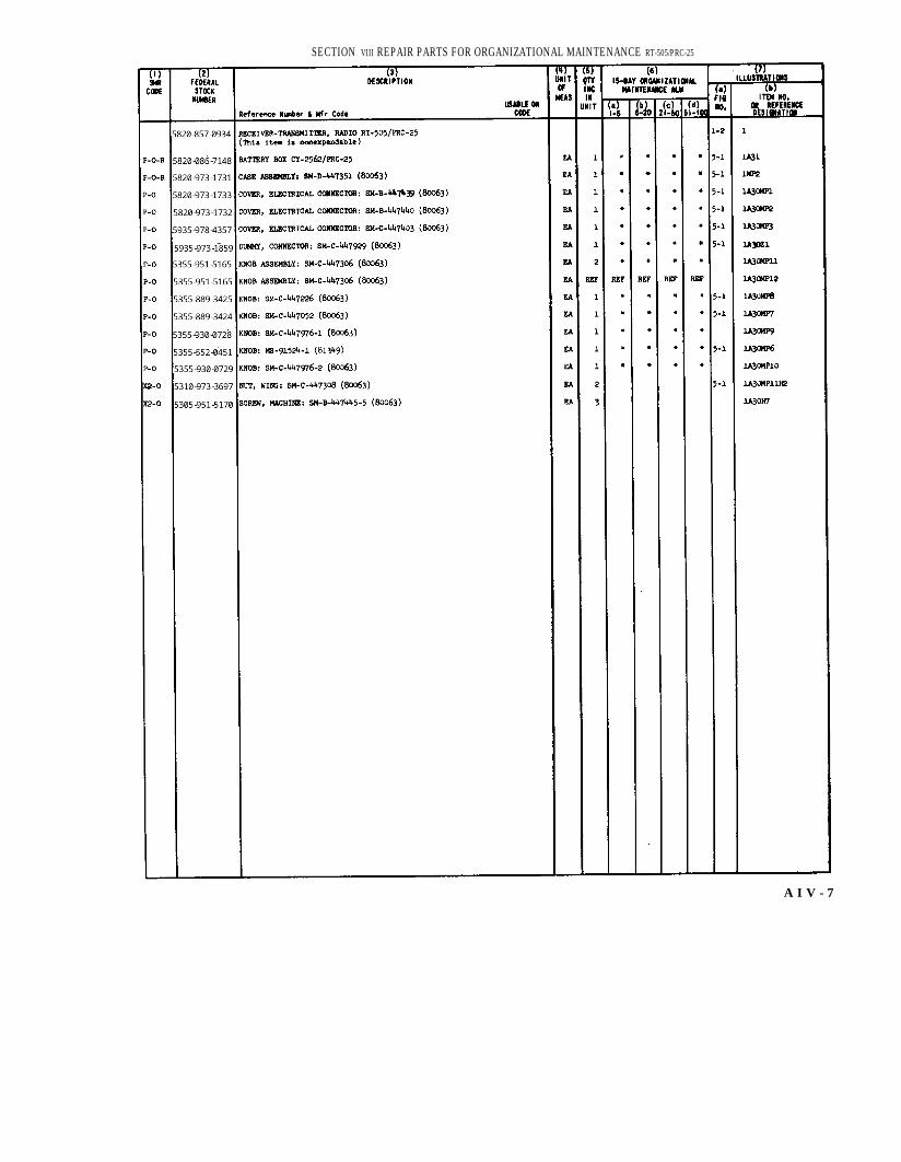
SECTION VIII REPAIR PARTS FOR ORGANIZATIONAL MAINTENANCE RT-505/PRC-25
A I V - 7
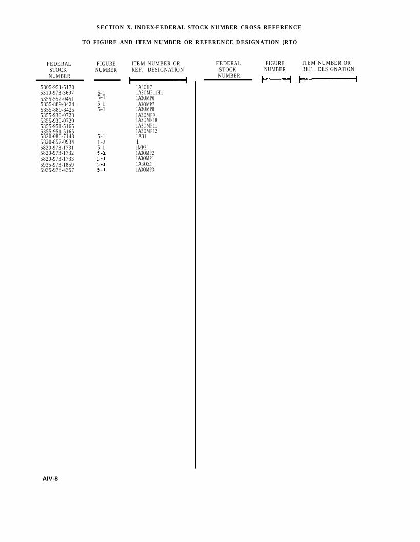
SECTION X. INDEX-FEDERAL STOCK NUMBER CROSS REFERENCE
TO FIGURE AND ITEM NUMBER OR REFERENCE DESIGNATION (RTO
FEDERALSTOCKNUMBER
5305-951-51705310-973-36975355-552-04515355-889-34245355-889-34255355-930-07285355-930-07295355-951-51655355-951-51655820-086-71485820-857-09345820-973-17315820-973-17325820-973-17335935-973-18595935-978-4357
FIGURENUMBER
5-15-1
5-15-1
5-11-25-1
ITEM NUMBER ORREF. DESIGNATlON
1A3OH71A3OMP11H11A3OMP61A3OMP71A3OMP81A3OMP91A3OMP101A3OMP111A3OMP121A3111MP21A3OMP21A3OMP11A3OZ11A3OMP3
FEDERAL FIGURE ITEM NUMBER ORSTOCK NUMBER REF. DESIGNATIONNUMBER
AIV-8

SECTION XI. INDEX-REFERENCE DESIGNATION
CROSS REFERENCE TO PAGE NUMBER (RT-505/PRC-25)
REFERENCE PAGE REFERENCE PAGEDESIGNATION
11MP21A30H71A30MP11A30MP21A30MP31A30MP61A30MP71A30MP81A30MP91A30MP10lA30MP111A30MP11H11A30MP121A30Z11A31
IV-8IV-8IV-8IV-8IV-8IV-8IV-8IV-8IV-8IV-8IV-8IV-8IV-8IV-8IV-8IV-8
REFERENCE PAGEDESIGNATION NUMBER .


TM 11-5820-398-12
By Order of the. Secretary of the Army:
Official:J. C. LAMBERT,Major General, United States Army,The Adjutant General.
Distribution:Active Army:
USASA (2)CNB (1)CC-E (7)Dir of Trans (1)CofEngrs (1)TSG (1)CofSpts (1)USAIB (5)USACDCEA (1)USACDCCBRA (1)USACDCOA (1)USAODCQMA (1)USACDCTA (1)USACDCADA (1)USACDARMA (1)USACDCAVNA (1)USAODCARYTA (1)USACDCSWA (1)USACDCCEA (1)USACDCCEA :
Ft Huachuca (1)USACDCEA ( 10)USAMC (5)USCONARC (5)ARADCOM (5)ARADCOM Rgn (5)OS Maj Comd (4)USAMERCC (5)LOGCOMD (2)USAMICOM (4)USASMC (2)USASCC (4)MDW (1)Armies (2) except
Seventh (5)Corps (2)USAc (8)llth Air Aalt Div (8)507th USASA Gp (5)508th USASA Gp (5)318th USASA Bn (5)310th USASA Bn (5)320th USASA Bn (6)177th USASA Co (6)182nd USASA Co (5)183rd USASA Co (5)184th USASA Co (5)SVC Colleges (2)Br Svc Sch (2) except
USASESOS (90)USAAMS (30)USAARMS (30)USAIS (30)USASCS (5)MFSS (5)USACSS (5)
USMA (5)GENDEP (2)Sig Sec GENDEP (5)Sig Dep (12)A DeP (2) except
SAAD (SC)TOAD (14)FTWOAD (10)LEAD (7)SHAD (8)NAAD (5)SVAD (5)CHAD (8)ATAD (10)LBAD (14)
USASTC (2)USATC AD (2)USATC Armor (2)USATC Engr (2)USATC Inf (2)USAATC (5)WRAMC (1)Army Pic Cen (2)Instl (2) except
Ft Monmoutb (70)Ft Hancock (4)Ft Gordon (10)Ft Huachuca (10)Pt Caraon (25)Ft Knox (12)Ft Devens (5)
WSMR (5)Sig Fid Maint Shops (2)AMS (1)USAERDAA (2)USAERDAW (18)lst GM Bde (5)USARSG (5)Units organized under following
TOE’'s (2 copies each) :1-7 1-551-87 1-56
HAROLD K. JOHNSON,General United States Army,Chief of Staff.
1-751-761-771-781-1001-1011-1071-2071-307
5-75-255-265-275-355-375-1165-1295-1455-1465-1475-1485-1555-1565-1575-2155-217
(AA-6-376-1OO6-1016-1556-1566-1576-1656-1666-1766-1766-1776-1856-186
6-2016-2156-2166-2176-2256-226

TM 11-5820-398-12
7-47-117-127-157-167-177-187-197-257-267-277-357-377-427-457-467-477-557-567-577-587-1008-25
8-268-278-679-79-179-229-479-1279-2179-3779-51011-3511-5711-9511-9711-9811-9911-11711-15511-15611-15711-33711-500
12-37
(AA-AC)11-58711-59211-597
1717-417-1517-1717-2717-3217-3517-3617-3717-4217-5117-5217-5517-5617-5717-5817-7517-76
39-6529-3529-36
29-52 55-5029-5529-56
55-54 55-56
29-65 55-58
29-97 55-89
55-407 32-673 2 - 6 8
32-500
NG: State AG (3).USAR : None.For explanation of abbreviations used, see AR 320-50.
17-7717-7817-9517-9717-9817-10017-10517-10617-10717-10817-20017-20117-20517-20617-20717-20819-27119-271 -
(AA-AE)29-l29-2
29-1129-1529-1629-2129-25
29-4129-51
29-75
31-10532-5632-57
32-77
37
37-437-4237-10039-51
44-84747-4255-47
55-57
55-59
55-99
55-4175757-457-4257-100
* U. S. GOVERNMENT PRINTING OFFICE : 1993 0 - 342-421 ( 62124)

TM 11-5820-398-12
Figure 6-17. AN/GRA-6 and RT-505/PRC-25 for remote radio control and RWI; connections and control settings. Change 3 6-25

TM5820-10-10
Figure 7-1 Retransmission interference chart (part 1 of 2).

TM5820-398-10-10
Figure 7-1. Retransmission interference chart (part 2 of 2).

TM5820-398-35-1
Figure 7-2. Receiver-Transmitter , Radio RT-505/PRC-25, schematic-block diagram
C 2, TM 11-5820-398-12


P I N : 0 1 8 8 1 6 - 0 0 0