tk150 rel 45_sg_v1.0
TRANSCRIPT

TK150 R45.0 V1.0 For Training Purposes Only 1

TK150 R45.0 V1.0 For Training Purposes Only 2
Table of Contents
Module 1 SIGTRAN Overview ……………………………….………………… 5
Module 2 Streaming Control Transport Protocol …………………………. 21
Module 3 Provisioning IPSG M2PA ..…………………………………………. 31
Module 4 Provisioning IPSG M3UA .…………………………………………. 63
Module 5 Verifying and Testing SIGTRAN .…….…………….……………… 81
Module 6 Analyzing IP Based Measurement Reports .……………………. 117

TK150 R45.0 V1.0 For Training Purposes Only 3

TK150 R45.0 V1.0 For Training Purposes Only 4

TK150 R45.0 V1.0 For Training Purposes Only 5

TK150 R45.0 V1.0 For Training Purposes Only 6

TK150 R45.0 V1.0 For Training Purposes Only 7
•SIGTRAN implements the SCTP protocol, which is a peer to TCP and UDP, but has
improvements. They also defined numerous adaptation layers that maintain MTP2 and/or
MTP3 functionality from the SS7 stack.
•IETF is an open standards organization supported by ANSI, ITU and ISO and is tasked to
provide standards for all aspects of Internet communications.
For further information on SIGTRAN, refer to RFC 4960

TK150 R45.0 V1.0 For Training Purposes Only 8
The SIGTRAN family of protocols used by the IPSG includes:
•MTP2 User Peer-to-Peer Adaptation Layer (M2PA)
•MTP3 User Adaptation Layer (M3UA)
•Stream Control Transmission Protocol (SCTP)
•The following features must be turned on for 1 Million TPS:
• HIPR2 High Rate Mode
• 1M System TPS

TK150 R45.0 V1.0 For Training Purposes Only 9
SS7 over IP requires that a path across the network must be defined in the STP that tells
the network where to deliver the packet.
An association is a path across a network. An association path is defined by the two
endpoints that it connects.
Delivery process:
•An MSC generates an SS7 MSU and sends it to the STP.
•MSUs are routed through the STP (based on the DPC) to the SIGTRAN card.
•SIGTRAN places the SS7 messages in the Data field, builds the packet header and then
sends the packet out the Ethernet port.
•The packet traverses the IP network.
•The packet is received at the destination STP.
•The SIGTRAN card extracts the SS7 MSU from the Data Field and routes it (based on
DPC) to the next linkset.
•The MSU is delivered to the MSC.

TK150 R45.0 V1.0 For Training Purposes Only 10
The Eagle adapts an SS7 MSU to transport it across Ethernet and IP using a SIGTRAN
Modules. E5 Ethernet Modules are:
• E5-ENET – Implements thirty-two (32) MTP3 links (A, A1, to A15 and B, B1, to B15) to
up to two physical ports at up to 5000 transactions per second. up to 6500 TPS while
running the IPSG application if the E5-ENET-B IPSG High Throughput feature is
turned on.
E5-ENET-B – Implements thirty-two (32) MTP3 links (A, A1, to A15 and B, B1, to B15)
to up to two physical ports at up to 9500 transactions per second.
•Delivering MSUs to Ethernet
• MSUs are delivered to one of the SS7 signaling link type application cards.
• The SS& link card sends the message to the SIGTRAN card via the IMT bus into an
SS7 MTP3 layer on the SIGTRAN module.
• SIGTRAN protocols place the MSUs into Ethernet packets and deliver them to Ethernet
networks.
• Each SIGTRAN module can use up to two independent Ethernet networks for reliability.
• Ethernet networks deliver MSUs to the distant end IP endpoints.

TK150 R45.0 V1.0 For Training Purposes Only 11
Each SIGTRAN card has two physical interfaces (Ethernet port A and Ethernet port B)
IP addresses are assigned to the SIGTRAN (E5-ENET/E5-ENET-B) card, not the STP.
All IP addresses related to the network for port A must belong to a different network than
the addresses for port B. (Using port B is optional).
Notice that the SIGTRAN card port must have the same network address as the router for
that network.

TK150 R45.0 V1.0 For Training Purposes Only 12
•E5-ENET or E5-ENET-B cards must communicate to Ethernet Switches (one per physical
interface).
•The local Ethernet network delivers packets to a Wide Area Network (WAN) which
delivers the packets to a distant Ethernet Local network.
•The distant IP Endpoint might be another STP or it might be some other IP signaling
device.
•SIGTRAN treats each MTP3 link as a separate application (program).
•The logical path from one MTP3 link at the near end to one MTP3 link (or its equivalent) is
called an “association”

TK150 R45.0 V1.0 For Training Purposes Only 13
NOTE: IP Signaling Gateway requires EAGLE Release 38.0.1 and above.

TK150 R45.0 V1.0 For Training Purposes Only 14
SIGTRAN Adaptation Layers
•The Data Chunk carries the Adaptation layer. The Chunk will consist of a SIGTRAN
management message or an actual MSU.
SIGTRAN protocols:
•M2PA – MTP2 Peer-to-Peer Adaptation layer
•M3UA – MTP3 User Adaptation layer
NOTE: SUA (SCCP User Adaptation) layer is NOT supported in IPSG.

TK150 R45.0 V1.0 For Training Purposes Only 15
•Application Servers are databases that respond to transaction based queries.
•The Media Gateway Controller receives call setup and call tear-down messages from the
EAGLE STP IPSG.

TK150 R45.0 V1.0 For Training Purposes Only 16
Application Servers (AS)
Implement Advanced Services
• Similar to SCPs but with many enhancements
• Unlike SCPs, Application Servers can initiate transactions
• Answer queries from SSPs
• Prepaid, postpaid, and automatic billing
• Multimedia services
• Voice over IP management and tracking
• Short Message Services
An Application Server has one Point Code and Link Set
Application Server Processes (ASPs)
• One AS can use multiple ASPs to support reliability and increased throughput through
load sharing.
• Eagle STP can be provisioned to load share among ASPs assigned to the same AS.
• Each ASP has one association. Each association connects to one MTP3 link (A, A1,
A2, etc). Each MTP3 link is one slc in the Link Set.
• Load sharing among MTP3 links is controlled by slc.

TK150 R45.0 V1.0 For Training Purposes Only 17
•SS7 over IP plays an important role in voice over Packet Network telephony.
•Media Gateway Controller (MGC) (Softswitch) provides the Media Gateway with the
directions that it requires to complete a call
• Receives call setup requests from SS7 packets across an IP network
• Translates each request into all of the commands an MG needs to complete the call
• One MGC can direct many MGs.
•
•Media Gateway (MG) converts among different voice protocols.

TK150 R45.0 V1.0 For Training Purposes Only 18
Converged Network Protocols
The above slide demonstrates SS7 messages that are routed through the STP through A,
B, C, and D links
•SS7 Messages are delivered to the next STP
•SS7 Messages are delivered to an Application Server
•SS7 Messages are delivered to a MGC

TK150 R45.0 V1.0 For Training Purposes Only 19

TK150 R45.0 V1.0 For Training Purposes Only 20
Module 1 Review
1. What standards body formed the SIGTRAN Working Group? __________
2. Name three SIGTRAN applications on the EAGLE: ____________________
3. IPSG supports both ANSI and ITU implementations on the same card.
True False
4. What IPSG endpoints respond to the transaction based queries?
________________________and __________________________
5. Which SIGTRAN implementation supports A, B, C, and D link sets?
______________
6. IPSG connects the STP to Application Servers. True False
7. Which node converts SS7 messages from SS7 to SIGTRAN?
____________
8. SIGTRAN cards provide how many Ethernet ports that connect the STP to
the Local Area Network? _________

TK150 R45.0 V1.0 For Training Purposes Only 21

TK150 R45.0 V1.0 For Training Purposes Only 22

TK150 R45.0 V1.0 For Training Purposes Only 23
•SIGTRAN uses SCTP as a transport protocol.
•RFC 4960 describes the SCTP Protocol
•SCTP connections are defined (provisioned) as an “Association” between two endpoints.
•SCTP connections support multi-homing.
•Each connection can have multiple “Streams”.
•Each stream can support multiple data chunks.

TK150 R45.0 V1.0 For Training Purposes Only 24
•ent-assoc always builds four streams
•Stream 0 is used for Management Messages
• Made up of two bi-directional streams
•Stream 1 is used for processing MSU traffic
• Made up of two b-directional streams
•Some devices support only two streams.
•The association can be modified to work with devices such as application servers..
•chg-assoc : aname = <name> : istrms=1 : ostrms=1

TK150 R45.0 V1.0 For Training Purposes Only 25
Each association has a unique name.
• All other commands reference the association by the association name.

TK150 R45.0 V1.0 For Training Purposes Only 26
TUPLE – parameters that define the IP addresses and SCTP ports to use for the local and
remote hosts.
1. Lhost (Local Host) – Hostname that represents the IP address of the local
Ethernet port on the SIGTRAN card (See IP-Host command)
2. Lport (Local Port) – SCTP port (any number greater than 10000). Tekelec
standard = SIGTRAN card slot location x 10
3. Rhost (Remote Host) - Host name that represents the IP address of the remote
host.
4. Rport (Remote Port) - SCTP port for the remote host application.
5. Alhost (Alternate Local Host) – An alternate local IP address that can be used for
this connection. The Alternate Local Host parameter (if defined) is used to
implement multi-homing. The Local Host and the Alternate Local Host must be
defined as different Ethernet Ports of the same SIGTRAN card.
6. Arhost (Alternate Remote Host) – An alternate remote name that represents the
IP address of the alternate remote host used in multi-homing.

TK150 R45.0 V1.0 For Training Purposes Only 27
•Multi-homing provides an alternate communications path in case the primary path fails.
•When SCTP initializes a connection, it will offer the local host and the alternate local host
(if provisioned) a usable IP address.
•The response from the remote end will list its local host and alternate local host as usable
IP addresses.
•If the Primary path fails, the SIGTRAN card will switch to the port for the alternate local
host and transmit packets to the alternate IP address for the remote.

TK150 R45.0 V1.0 For Training Purposes Only 28

TK150 R45.0 V1.0 For Training Purposes Only 29
Module 2 Review
1. The ________ protocol replaces TCP and provides Multi-homing, Streams, and Data
Chunks.
2. Which parameter of the TUPLE implements multi-homing? __________
3. Having multiple segregated paths in one association is provided by?
a. Chunks b. M2PA c. Streams d. IP Header
4. List the two SIGTRAN adaptation layers implemented by TEKELEC
___________________________________________
5. Which adaptation layer is used for IPLIM applications? _________________

TK150 R45.0 V1.0 For Training Purposes Only 30
Course Notes

TK150 R45.0 V1.0 For Training Purposes Only 31

TK150 R45.0 V1.0 For Training Purposes Only 32

TK150 R45.0 V1.0 For Training Purposes Only
In this slide, the solid lines indicate the local and remote hosts and the dotted lines indicate
the alternate local hosts.
33

TK150 R45.0 V1.0 For Training Purposes Only 34
•This slide depicts the recommended order of data entry into the EAGLE 5 STP.
•Assuming that initial EAGLE 5 Signaling Gateway configuration has been performed, the following
steps for IPSG M2PA configuration are:
• SS7 configuration Part A
• Add SIGTRAN cards – ent-card
• Add Destination Point Codes - ent-dstn
• Add linksets - ent-ls
• IP configuration
• Define IP and Ethernet parameters for each port – chg-ip-lnk
• Assign host names to IP addresses – ent-ip-host
• Set default router, DNS servers (if used) and search order – chg-ip-card
• Define a second router when both Ethernet ports on a card are used – ent-ip-rte
• Configure SCTP associations from the local host and port to the remote host and port
– ent-assoc
• SS7 configuration Part B
• Add signaling links – ent-slk
• Add routes – ent-rte
• SS7 and SIGTRAN activation
• Put the SIGTRAN cards into service - alw-card
• Put the signaling links into service – act-slk
• Change the associations to open and allow traffic on the associations – chg-assoc

TK150 R45.0 V1.0 For Training Purposes Only 35
Parameters used are:
:appl- the application running on this card
:loc-the physical card slot location of the card
:type-the type of card being entered
IPSG supports protocols M2PA and M3UA, but not SUA.
Fill in the command parameters for the example network
ent-card:type=______________:appl=______________:loc=______________

TK150 R45.0 V1.0 For Training Purposes Only 36
Parameters used are:
:dpc – the destination point code in the form of ANSI, ITU-I, or ITU-N
:bei – broadcast exception indicator, determines if network management messages are
transmitted to the point code, values of yes, or no
yes indicates messages are not broadcast
no indicates messages are broadcast
:clli – common language location identifier – indicates physical location of signaling
point
Up to 2,800 destinations may be provisioned on the EAGLE
Fill in the command parameters for the example network
ent-dstn:dpc=_______________:clli=________________:bei=__________

TK150 R45.0 V1.0 For Training Purposes Only 37
Parameters used are:
:apc- the point code at the far end of the linkset
:lsn- linkset name
:lst-linkset type, m2pa uses B,C &D linkset types
m3ua uses A linkset type only
:adapter – m2pa or m3ua
:ipsg=yes for IPSG linksets
slktps – the number of transactions per second (TPS) that is assigned to each IPSG
signaling link that will be in the linkset, from 100 to 5,000.
lsusealm – specifies the percent of the linkset TPS at which an alarm is generated to
indicate that the actual linkset TPS is approaching the configured iptps value for the linkset
slkusealm – specifies the percent of the link “fair share” TPS at which an alarm is
generated to indicate that the actual link TPS is approaching the link’s fair share of its
linksets configured TPS (iptps). The fair share of the linkset TPS for a link is the configured
linkset TPS divided by the number of in-service links in a linkset.
Fill in the command parameters for the example network
chg-ls:lsn=_______________:lst=_____:apc=_______________________
:adapter=________________:ipsg=__yes_____

TK150 R45.0 V1.0 For Training Purposes Only 38
•Alarm 0116, slkusealm trips when the transactions across at least one link in a link set
exceed the signaling link fair share value.
•The signaling link fair share is the sltps times the number of links in a link set.
Let’s take an example where we have 4 links in a link set. It does not matter whether the
links are on the same card or not. The slktps is set to 1000, lsusalm is set to 80%, the
slkusealm is set to 60%
Example 1: (First row on table above) All links are in service. The total Link Set tps=
1000tps/slk * 4 slks= 4000 tps. The link set will trip alarm 0115 if the total tps in the link set
exceeds 4000tps/ls * 80% = 3200 tps. The slk fare share is 4000 tps/ls div 4 links = 1000
tps. The slkusalm will trip at 60% of the fare share (1000tps/slk * 60% = 600 tps.)
Example 2: (Second row on table above): One link is out of service. The lsusealm still trips
at 3200 tps, but now the slkusealm doesn’t trip until 800 tps.
In this way, as two links go out of service, the lsusealm is still 3200 tps, but now the
slkUsealm doesn’t trip until 1200 tps.
With three links out, lsusealm is still 3200 tps, but the slkUsealm is way up at 2400 tps.
TK150 R45.0 V1.0 For Training Purposes Only 39
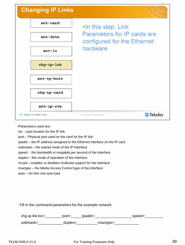
•Parameters used are:
:loc - card location for the IP link
:port – Physical port used on the card for the IP link
:ipaddr – the IP address assigned to the Ethernet interface on the IP card
:submask – the subnet mask of the IP Interface
:speed - the bandwidth in megabits per second of the interface
:duplex – the mode of operation of the interface
:mcast – enables or disables multicast support for the interface
:mactype – the Media Access Control type of the interface
:auto – Do Not Use auto=yes
Fill in the command parameters for the example network
chg-ip-lnk:loc=________:port=_____:ipaddr=__________________:speed=_________
submask=____________:duplex=__________:mactype=____________

TK150 R45.0 V1.0 For Training Purposes Only 40
•Parameters used are:.
:host – the host name to be associated with the IP address
:ipaddr - the IP address to be associated with the hostname
:type - specifies if the host resides on the local or remote end of the IP link
•Host name format example:
location name card type card location ethernet port
rlgh enet 1101 a
:
Fill in the command parameters for the example network
ent-ip-host:host=_______________:ipaddr=______________________:type=_______

TK150 R45.0 V1.0 For Training Purposes Only 41
•Parameters used are:
:loc – the card location of the IP card
:srchordr – the host table search order
:dnsa – domain name server A IP address
:dnsb – domain name server B IP address
:defrouter – Default router IP address
Fill in the command parameters for the example network
chg-ip-card:loc=__________:srchordr=_________:defrouter=______________________

TK150 R45.0 V1.0 For Training Purposes Only
•Parameters used are:
::loc – the location of the IP card that the IP route will be assigned to
:dest – the IP address of the remote host or network
:submask – the subnet mask of the destination IP address
:gtwy – the IP address of the gateway or router that will send the IP data to its final
destination
42
Fill in the command parameters for the example network
ent-ip-rte:loc=__________:dest=__________________:submask=__________________
:gtwy=____________________

TK150 R45.0 V1.0 For Training Purposes Only
•Parameters used are:
:aname – the name assigned to the association
:lhost – local hostname
:lport – the SCTP port number of the local host
:rhost – remote hostname
:rport – the SCTP port number of the remote host
:adapter – the adapter layer for the association, m2pa or m3ua
:alhost – the alternate local host name used for multi-homing
43
Fill in the command parameters for the example network
ent-assoc:aname=_______________:lhost=_____________________:adapter=_______
:lport=___________:rhost=_______________:rport=_______________
:alhost=____________

TK150 R45.0 V1.0 For Training Purposes Only 44
•The chg-assoc command can be used to provide the alternate path to fail over to if the
primary path fails
•The path is from alhost to rhost.
•rhosttype = alternate says that the rhost this time is an alternate host, not a primary host.
•rhostval can have any one of two values
relaxed – The remote host can be negotiated when the association is established. If the
other end offers a new rhost, use that one. If you set this mode, then rhost and
rhosttype are both optional. The drawback to this mode is that if the primary path fails
and the association goes down, it cannot come back up on the alternate path.
match – (Sometimes known as strict mode.) When the association comes up, the other
end must offer this host IP address as the alternate. If it does not the link cannot come
up. The other end must be RFC 4666 compliant for this mode to work. The advantage
of this mode is that if the primary path fails, the association can go down and come up
on the alternate path. If the primary path fails, the alternate then becomes primary for
all practical purposes.

TK150 R45.0 V1.0 For Training Purposes Only
•Parameters used are:
:loc – location of link Interface card supporting the signaling link
:lsn – name of the linkset the signaling link is a part of
:link – signaling link port of the signaling link card
:slc – signaling link code – a unique value for a each link in a linkset
:aname – the association name assigned to a signaling link assigned to an IPSG linkset
45
Fill in the command parameters for the example network
ent-slk:loc=________:link=_____:lsn=________________:slc=_________
:aname=_________________________

TK150 R45.0 V1.0 For Training Purposes Only
•Parameters used are:
:dpc – point code of the signaling point in which the route is being configured
:lsn – name of the linkset being used for this route
:rc – relative cost of the route, with a value of 0-99, lowest value indicates most preferred
route, and highest value indicates least preferred route
46
Fill in the command parameters for the example network
ent-rte:dpc=______________________:lsn=________________________:rc=______

TK150 R45.0 V1.0 For Training Purposes Only
•Parameters used are:
:loc – physical location of enet card
47
Fill in the command parameters for the example network
alw-cards:loc=___________

TK150 R45.0 V1.0 For Training Purposes Only
•Parameters used are:
:loc – physical location of LIM card
:link – signaling link port used for the link.
48
Fill in the command parameters for the example network
act-slk:loc=_______________:link=_____

TK150 R45.0 V1.0 For Training Purposes Only
•Parameters used are:
:aname – the name assigned to the association
::alw=yes
:open=yes
49
Fill in the command parameters for the example network
chg-assoc:aname=_______________:alw=________:open=_________

TK150 R45.0 V1.0 For Training Purposes Only 50
•rept-stat-assoc: The association on the adjoining node must be provisioned and allowed.
Allow a few minutes after the card is allowed for it to build an IP stack
•rept-stat-card: Make sure the card is “IS-NR” (In Service and Normal)
•rept-stat-slk: Make sure the link comes up normal
•pass: We will discuss the format of the pass commands in the maintenance section. For
now, just copy the command as shown, substituting the link (a, a1). Do this for each link
you have provisioned.

TK150 R45.0 V1.0 For Training Purposes Only 51

TK150 R45.0 V1.0 For Training Purposes Only 52

TK150 R45.0 V1.0 For Training Purposes Only 53

TK150 R45.0 V1.0 For Training Purposes Only 54

TK150 R45.0 V1.0 For Training Purposes Only 55

TK150 R45.0 V1.0 For Training Purposes Only 56
Learning Activity 1: Provisioning IPSG M2PA
1. Login to your assigned STP
Login:uid=eagle
(password) eagle
2. We must enter the card, create the required destination and change a linkset.
3. Enter the SIGTRAN card
ent-card (loc, type, appl)
4. From the assigned lab diagram, determine the point code of the STP on the far end of the
linkset. Record here: ___________
5. Retrieve the current destinations and verify that the far end point code already exist
rtrv-dstn
6. Review output verifying the point code at the far end.
7. If the far end STP point code already exists, skip the ent-dstn and continue with linkset
provisioning, or else enter the following command
8. Enter the destination for the remote STP
ent-dstn (dpc, clli, bei)
the clli (silly) code is the common language location identifier (dallas, bolder, …)
9. The next step is linkset provisioning. First, retrieve the provisioned linksets:
Hint: KSR mode (F11) may work best for this command
rtrv-ls
10. A linkset should already exist to the far end point code. Record the linkset name of the “C”
linkset to your mate STP.
_________________
11. Change the linkset.
chg-ls:ipsg= yes: lsn = <from above>
chg-ls:lsn =<from above> : slktps = 1000 : adapter=M2PA
12. We need to assign an IP address, submask and other Ethernet parameters for BOTH
Ethernet ports on the SIGTRAN card:

TK150 R45.0 V1.0 For Training Purposes Only 57
Learning Activity 1: Provisioning IPSG M2PA 13. Since we are using multi-homing BOTH Ethernet Ports must be provisioned
Optional: rtrv-ip-lnk to see the defaults
chg-ip-lnk (loc, port, ipaddr, submask=255.255.255.0, duplex=full, speed=100, auto=
no, mcast=no, mactype=dix)
14. (repeat for BOTH Ethernet ports)
15. The IP and Ethernet parameters are now complete. Next is the host table and association.
16. Fill in the table below for all hostnames.
17. Enter Host Names (4 Host; 2 local, 2 remote)
ent-ip-host (host, ipaddr, type)
18. Change the IP card parameters
chg-ip-card:loc=xxxx (card location):srchordr=local
19. Before entering the association, complete the following table:
Local Hostname Remote Hostname
Port = A
Port = B
Associ
-ation
Aname Lhost Lport Alhost Rhost Rport Adapter
Port A
Port B

TK150 R45.0 V1.0 For Training Purposes Only 58
Learning Activity 1: Provisioning IPSG M2PA 20. Enter two associations with MULTI-HOMING
ent-assoc (aname, lhost, lport, rhost, rport, adapter)
chg-assoc (aname, alhost)
21. To determine what links are in the linkset, retrieve the details of the linkset:
rtrv-ls: lsn=<linksetName>
22. Record the following link information:
23. We have two existing low speed links in the linkset. We will delete a link (slc=0) and replace
it with a link on the SIGTRAN card.
24. Before you can delete a link, you must deactivate the link:
dact-slk: loc= : link=<link> (from above)
dlt-slk: loc=: link=<link>
25. Enter the IP signaling link with a slc value=0
ent-slk (loc, link, slc, lsn, aname)
26. Retrieve the associations and check your work
rtrv-assoc
27. Check to see if there are any routes in the database.
rtrv-rte
28. If routes already exist, skip ent-rte and go to allow card
29. Enter a route for each SSP point code to use the C link
ent-rte (dpc, lsn, rc=30)
Location Link SLC

TK150 R45.0 V1.0 For Training Purposes Only 59
Learning Activity 1: Provisioning IPSG M2PA
30. It is now time to turn up the first IP link.
31. Allow card, activate link, and open and allow association.
alw-card: loc=xxxx
act-slk: loc=xxxx:link=xxxx
chg-assoc:aname=xxxx:open=yes:alw=yes
32. We will now delete the second low speed link (slc=1)
33. Before you can delete a link, you must deactivate the link:
dact-slk: loc= : link=<link> (from above)
dlt-slk: loc=: link=<link>
34. Enter the IP signaling link with a slc value=1
ent-slk (loc, link, slc, lsn, aname)
35. Retrieve the associations and check your work
rtrv-assoc
36. It is now time to turn up the second IP link.
37. Allow card, activate link, and open and allow association.
alw-card: loc=xxxx
act-slk: loc=xxxx:link=xxxx
chg-assoc:aname=xxxx:open=yes:alw=yes
STOP! Inform the instructor you have completed the lab.

TK150 R45.0 V1.0 For Training Purposes Only 60

TK150 R45.0 V1.0 For Training Purposes Only 61
Module 3 Review
1. Which command assigns an IP address to a port on the SIGTRAN card?
________________________
2. Which command is used to define the srchordr parameter?
_________________________
3. What command do you use to place an association in service?
________________________
4. Which parameter in the 5 TUPLE defines the Ethernet port that will be used
for the primary connection? _____________________
5. SS7 messages are routed across the STP backplane to the SIGTRAN card
based on the DPC (Destination Point Code). True or False
6. SS7 messages are delivered across the IP network by using an association.
True or False
7. The SS7 link (a, a1, a2, etc.) determines which association is used.
True or False

TK150 R45.0 V1.0 For Training Purposes Only 62
Course Notes

TK150 R45.0 V1.0 For Training Purposes Only 63

TK150 R45.0 V1.0 For Training Purposes Only 64

TK150 R45.0 V1.0 For Training Purposes Only 65

TK150 R45.0 V1.0 For Training Purposes Only 66
•This slide depicts the additional data entry necessary for M3UA configuration.
• IP configuration
• Enter a link set – ent-ls
• Enter a network appearance in the network appearance table – ent-na
• Enable the Bearer Independent Call Control feature – enable-ctrl-feat
•SS7 and SIGTRAN activation
• Put the SIGTRAN cards into service - alw-card
• Put the signaling links into service – act-slk
• Change the associations to open and allow traffic on the associations – chg-assoc

TK150 R45.0 V1.0 For Training Purposes Only 67
lsn- Linkset name
apc- The DPC of the Application Server (ASPs do not have Point Codes)
ipsg=yes
slktps= (See M2PA slktps)
lsusealm= (See M2PA lsusealm)
adapter=m3ua
rcontext= This is essentially an optional security measure for communicating with
Application Servers. If an Application Server is configured with a routing context
number, then the Link Set must be provisioned with the same exact number (from 1 to
4294967295).
It acts as a filter, filtering out ASP active and Inactive messages when the numbers
don’t match. It locks in DPC, OPC, and SI values so that once the link is established,
other devices that do not have the routing context cannot interfere with communication
to the ASPs.
ASNotify=yes/no. Do you want to notify the Application Server of changes in status in
the ASPs? This should be set to match the needs of the equipment you are
communicating with. Some AS want it on, some want it off.
Fill in the command parameters for the example network
ent-ls:lsn=_______________:lst=_____:apc=____________:ipsg=_______:adapter=______

TK150 R45.0 V1.0 For Training Purposes Only
•Network appearance identifies the SS7 network context of the message, for the purposes
of logically separating signaling traffic between the Signaling Gateway Process and ASP
over a common SCTP association. Use this command to enter a new network appearance
in the Network Appearance table.
•A unique network appearance value can be associated with ANSI, ITUI, 14-bit ITU-N or
24-bit ITU-N networks.
•When the ITUDUPPC ( ITU National Duplicate Point Code) feature is turned on, network
appearance can be associated with a specific 14-bit ITU-N group code.
•The network appearance table can contain a maximum of 45 entries
68
Fill in the command parameters for the example network
ent-na:na=_____________:type=__________:gc=_______________

TK150 R45.0 V1.0 For Training Purposes Only 69
•BICC ITU-T Q.1901
Bearer Independent Call Control protocol is a call control protocol used
between serving nodes. This protocol is based on the ISUP protocol, and was adapted to
support the ISDN services independent of the bearer technology and signaling message
transport technology used.
TK150 R45.0 V1.0 For Training Purposes Only
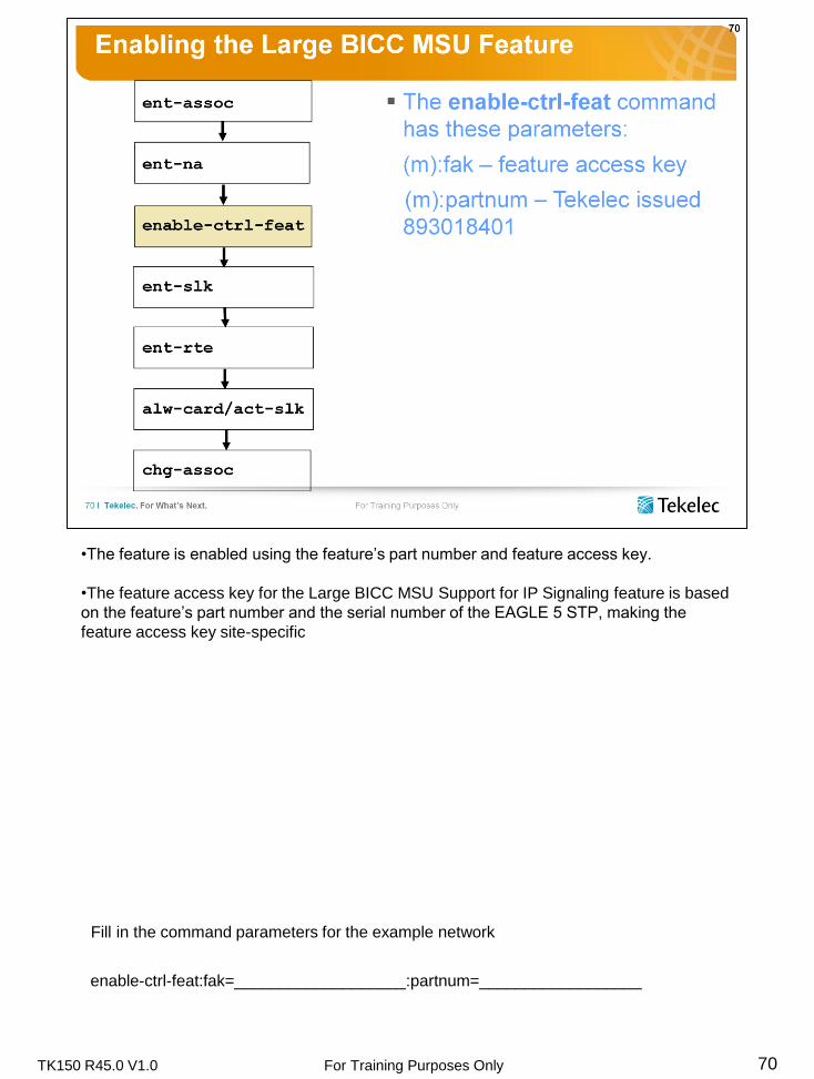
•The feature is enabled using the feature’s part number and feature access key.
•The feature access key for the Large BICC MSU Support for IP Signaling feature is based
on the feature’s part number and the serial number of the EAGLE 5 STP, making the
feature access key site-specific
70
Fill in the command parameters for the example network
enable-ctrl-feat:fak=___________________:partnum=__________________

TK150 R45.0 V1.0 For Training Purposes Only 71

TK150 R45.0 V1.0 For Training Purposes Only 72

TK150 R45.0 V1.0 For Training Purposes Only 73

TK150 R45.0 V1.0 For Training Purposes Only 74

TK150 R45.0 V1.0 For Training Purposes Only 75

TK150 R45.0 V1.0 For Training Purposes Only 76
Learning Activity 2: Provisioning IPSG M3UA
1. Login to your assigned STP
Login:uid=eagle
(password) eagle
2. Next we will do SS7 commands (ent-card, ent-dstn, ent-ls).
3. Enter the card
ent-card (loc, type, appl)
4. Before creating the destinations for the application server , check to see if the point codes
already exist. If not got to step 5.
rtrv-dstn
5. Create the destinations for the AS.
ent-dstn (dpc, cilli, bei, ipgwapc)
6. Enter the linkset – the linkset for IPGW has several new parameters.
ent-ls (apc, lst, lsn, adapter, ipsg, slktps, lsusealm=80, slkusealm=80)
apc – specifies the adjacent point code
lst = specifies the linkset type
lsn = specifies the linkset name
adapter - specifies the adapter layer for links provisioned in a IPSG linkset
ipsg - specifies whether a linkset is entered for an IPSG card.
slktps – defines how much of the system transactions per second (IPTPS) should be
allocated for this linkset)
lsusealm – defines the alarm threshold for the linkset. Is a percentage of the iptps
parameter
slkusealm – defines the alarm threshold for each link. Is a percentage of the iptps
parameter
7. Change the IP Link parameters
chg-ip-lnk (loc, port, ipaddr, submask=255.255.255.0, duplex=full, speed=100, auto=
no, mcast=no, mactype=dix)

TK150 R45.0 V1.0 For Training Purposes Only 77
Learning Activity 2: Provisioning IPSG M3UA
8. Enter Host Names for the IPSG Ethernet port, IP address and type ( there will two entries,
one for the local host, and one for the remote host)
ent-ip-host (host, ipaddr, type)
9. Change the IP card parameters
chg-ip-card (srchordr=local)
10. Enter the associations for the IPSG two ASPs
ent-assoc (aname, lhost, lport, rhost, rport, adapter=M3UA)
11. Enter the Network Appearance
ent-na (na, type)
The na will be”1” for the ASPs associated with the assigned network
enter once for the ASPs associated with the assigned network, i.e. Raleigh/Clayton,
Dallas/Hubbard, Denver/Salt lake, or Heathrow/Gatwick.
13. Enter a signaling link on the SIGTRAN card for the linkset created in step 9.
ent-slk : (loc, link, lsn, slc, aname*)
14. Enter the routes to the AS over the IPSG M3UA linkset
ent-rte : (dpc, lsn, rc=10)
15. Enable the BICC Control feature using the enable ctrl-feat command.
Partum=893018401
Fak=CFV9HRM55737C
16. Activate the BICC Control feature using the chg-ctrl-feat command.
This completes the IPSG M3UA setup. Time to put things in service.
17. Allow card, activate links, and open and allow associations.
a. alw-card (loc)
b. act-slk (loc, link)
c. chg-assoc (aname, open)
Note: If the value specified for the aname parameter refers to an M3UA
association on an IPSG card, then the alw parameter cannot be specified.
STOP! Notify your instructor you have completed the lab.
* “aname” value must match the entry in step 11.

TK150 R45.0 V1.0 For Training Purposes Only 78

TK150 R45.0 V1.0 For Training Purposes Only 79
Module 4 Review
1. Which parameter in the ent-ls command provides security by locking in an
OPC, DPC, and SI? _____________
2. The ent-na command assigns a network appearance to a specific
SIGTRAN card provisioned in the Eagle STP. True or False
3. BICC guarantees faithful delivery of ___________messages from one MGC
to another.
4. In IPSG M3UA, there must be one signaling link and association for every
_________________________________in the Application Server
5. In IPSG M3UA, the ent-slk command must come after the ent assoc
command. Why?
__________________________________________________________
___________________________________________________________

TK150 R45.0 V1.0 For Training Purposes Only 80
Course Notes

TK150 R45.0 V1.0 For Training Purposes Only 81

TK150 R45.0 V1.0 For Training Purposes Only 82

TK150 R45.0 V1.0 For Training Purposes Only 83

TK150 R45.0 V1.0 For Training Purposes Only 84

TK150 R45.0 V1.0 For Training Purposes Only 85

TK150 R45.0 V1.0 For Training Purposes Only 86

TK150 R45.0 V1.0 For Training Purposes Only 87
• The rept-stat-card command also shows information not depicted on this slide concerning GPL
versions, IMT bus status and card temperature information
• The rept-stat-card : mode = full command will provide TVG status details
Note: You must enter the card slot location to use the “mode=full” parameter

TK150 R45.0 V1.0 For Training Purposes Only 88
rept-stat-assoc
Reports status for all associations
TK150 R45.0 V1.0 For Training Purposes Only 89
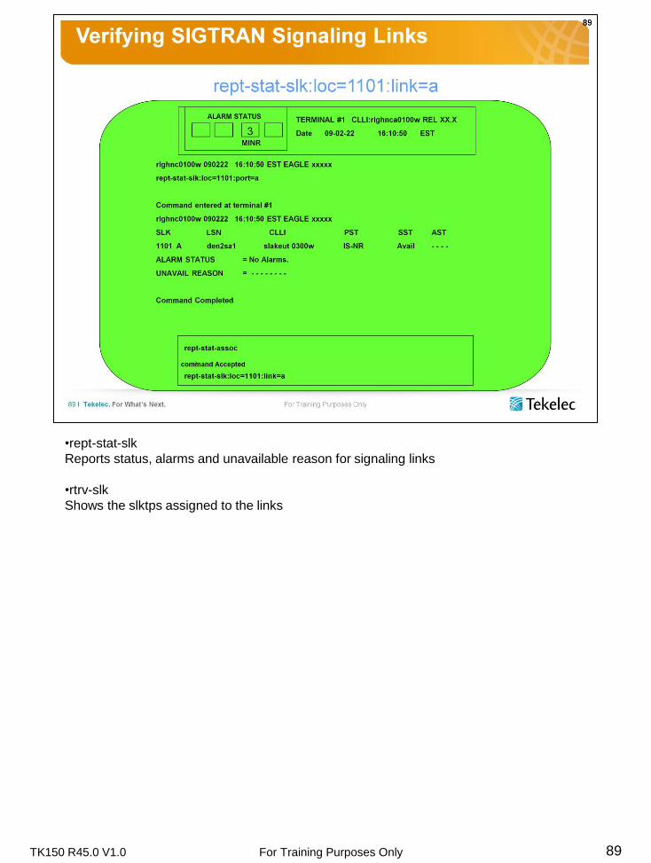
•rept-stat-slk
Reports status, alarms and unavailable reason for signaling links
•rtrv-slk
Shows the slktps assigned to the links

TK150 R45.0 V1.0 For Training Purposes Only 90
The rept-stat-iptps command is used to display the current and peak IPTPS usage for
each IPSG linkset in the system or for each link in the IPSG linkset
• Reports the current number of transactions and peak transactions per second
• Reports on IPSG M2PA and M3UA
• Reports on IPGW
• Command uses (Number of IS-NR links * SLKTPS) in place of the IPTPS setting for all
calculations and alarms.
• If the linkset is specified with the peakreset=yes parameter, then the command
recalculates peaks for the specified linkset and resets all the stored peak values to the
current actual usage for each link contained in the linkset before reporting usage.

TK150 R45.0 V1.0 For Training Purposes Only 91
Pass Command Syntax:
•Inside the quoted portion, you don’t use colons as separators
•Inside the quoted portion, you don’t use parameter=value pairs
See the “Pass-through Commands” chapter of the Commands manual of the user
documentation for a complete list of pass commands.

TK150 R45.0 V1.0 For Training Purposes Only 92

TK150 R45.0 V1.0 For Training Purposes Only 93
Pass Commands Examples
•aslog <applicationServer>
•assocrtt <associationName>
•connmgr –n
•linkinfo <link> –l
•msucount –l a
•msucount –a <associationName>
•netstat –p sctp
•sctp –a <associationName>
NOTE: The MSUTRACE pass command should be used only by request of Tekelec
support centers.

TK150 R45.0 V1.0 For Training Purposes Only 94
•Ping: Isolate breaks in the communications path using regular isolation methods. Ping
yourself, ping the far end, ping routers along the way until you have located the area of
communications breakdown. Copy and paste a host name from the ent-assoc command to
verify that you have typed it right.
•NSLookUp: Not very useful unless you are using DNS servers.
•arp –a: This shows MAC and IP addresses. If IT doesn’t tell you what the default routers
are, they will show up in this report.
•arp -f: This flushes all of the MAC addresses out of the buffer. If you change protocols or
MAC type, you will have to flush buffers on both ends of the association before it will come
up.
•netstat –p sctp: Shows aggregated report of all the sctp buffers on the card. Use this to
identify overall problems then isolate with sctp command (later).
•traceroute: The roundtrip time should be under 120 ms for basic functionality, and lower
than 40 to 70 msec for full bandwidth. If the roundtrip time begins to drop (see assocrtt),
use this to see what routers your messages are going through and how much delay each
router is introducing. Warning- This command uses UDP protocol. Your SCTP packets
might not follow exactly the same path.

TK150 R45.0 V1.0 For Training Purposes Only 95
connmgr –d: Displays a list of all MTP3 links (a, a1, a2, etc.) and whether they are connected to the
sctp layer correctly
connmgr –i: Shows an instance of an SCTP connection. If an SCTP connection is bouncing, this
number will continually change to show that. Also, this list shows how many SCTP connection
requests were refused by the other end.
connmgr –l: This provides a log of all changes in status. If connmgr –I shows a refused connection,
this log will show the date and time of the refusal and what events went on around that time.
connmgr –n: This provides a log of association status. If associations bounce, this log will show
when the link bounced and what commands were involved.
connmgr –r: (Reset) Clears all connmgr measurements and logs.
sctp –a [aname]: This report displays provisioned information plus it displays SCTP
performance information similar to netstat –p sctp. The difference is that the information will be
for a specific association instead of generic to all associations on the card. Note- This will only
reports on SCTP associations that are up. If the association is not coming, refer to connmgr –n
to see why not.
sctp –l: This provides a log of maintenance messages issued on both the data stream and the
maintenance stream. The date and time and the “reason” the message was issued are
especially valuable.
sctp –r: This resets all sctp logs and measurements.
assocrtt [aname]: For associations to work correctly, acknowledgements must be returned within
120 msec of when they went out. For full performance, this round trip time has got to be under
40 to 70 msec. Do not use Ping to time this. This command is used for diagnostic purposes as
well as setting congestion windows and retransmit times.
assocrtt [aname] –r: Resets assocrtt statistics. Use this to measure performance over specific

TK150 R45.0 V1.0 For Training Purposes Only
periods. Issue this at the beginning of the period. Then issue assocrtt [aname] at the end of the
period to discover how much they varied over that period.
95

TK150 R45.0 V1.0 For Training Purposes Only 96
linkinfo [slk] –a: Provides a time stamped log of link changes in link states. It can report changes
from MTP3 to MTP3 (State) or changes between MTP3 to M2PA (m2pa). Which of these are
reported are determined by the –i, -x, and –v switches.
linkinfo [slk] –l: Provides a time stamped log of primitives. Primitives are messages are issued
between layers. The –i,-x, and –v switches can be selected to determine which primitives will
be displayed. The report can include messages between MTP3 and SCTP (l3l2), SCTP to
MTP3 (l2l3), data, and service messages. Which reports are included depend on –i, -x, -v
switches.
linkinfo [slk] –r –a: Resets the link change log.
linkinfo [slk] –r –l: Resets the SCTP primitive log.
msucount –a [aname]: Counts MSUs received and transmitted on a given association. It also counts
bytes.
msucount –l [slk]: Counts MSUs received and transmitted on a given signaling link. It also counts
bytes.
msucount –r : Resets the counts of MSUs received and transmitted.
msutrace: Do not use this command unless directed to by Customer Service. They will walk you
through it at that time.

TK150 R45.0 V1.0 For Training Purposes Only 97

TK150 R45.0 V1.0 For Training Purposes Only 98

TK150 R45.0 V1.0 For Training Purposes Only 99

TK150 R45.0 V1.0 For Training Purposes Only 100

TK150 R45.0 V1.0 For Training Purposes Only 101

TK150 R45.0 V1.0 For Training Purposes Only 102

TK150 R45.0 V1.0 For Training Purposes Only 103

TK150 R45.0 V1.0 For Training Purposes Only 104

TK150 R45.0 V1.0 For Training Purposes Only 105

TK150 R45.0 V1.0 For Training Purposes Only 106

TK150 R45.0 V1.0 For Training Purposes Only 107

TK150 R45.0 V1.0 For Training Purposes Only 108
Useful tools for verifying SIGTRAN issues are:
• EAGLE UAMs and UIMs
• Enter the command chg-trm:all=yes:trm=x to see all messages generated by the
EAGLE 5 STP
• wireshark (ethereal)
• Eagle Documentation
• RFCs

TK150 R45.0 V1.0 For Training Purposes Only 109

TK150 R45.0 V1.0 For Training Purposes Only 110
Course Notes

TK150 R45.0 V1.0 For Training Purposes Only 111
Learning Activity 3: Database Maintenance
Provides hands-on practice in using the EAGLE STP Database Administration Manual -
SS7, STP, and user interface for database backup procedures.
After completing this exercise, you will be able to:
Backup database to the fixed disk and either a removable cartridge or USB drive
Materials, Equipment, and References
EAGLE STP
EAGLE STP Interface Terminal
Anti-Static Wrist Strap
EAGLE STP Database Administration Manual - SS7
Removable Cartridge
USB drive

TK150 R45.0 V1.0 For Training Purposes Only 112

TK150 R45.0 V1.0 For Training Purposes Only 113
Learning Activity 3: Testing
1. Login to your assigned STP
a. Login:uid = eagle
(password) = eagle
2. Check the status of the SIGTRAN card.
a. rept-stat-card : loc = <slotNum>
b. Record the Primary State of the card (PST): ____________
c. How many signaling links (SLK) are on this card? _________
d. What is the PST of the links? __________________
3. Retrieve the association names
a. rtrv-assoc
4. Record the first association name: _______________
5. Report status for the association
a. rept-stat-assoc : aname = <from last step>
6. Record the following information:
a. Card locations for the SIGTRAN card: _______
b. Which Ethernet port is used? _______ (IPLINK PORT)
c. If both Ethernet ports are used, why? ___________________
d. The SS7 Link: _______
e. Primary State of the Association: _____________

TK150 R45.0 V1.0 For Training Purposes Only 114
Learning Activity 3: Testing
7. Report more information on an SS7 Link
a. rept-stat-slk : loc = <slot> : link = a
b. Record the Primary State (PST) for the link: ____________
c. Record the Secondary State (SST) for the link: ___________
d. If PST is not IS-NR; record the “unavail reason”: ______________
8. Try the following Pass commands: (KSR mode - F11)
a. pass : loc = <slot> : cmd=“ping <farEndIP>”
b. pass : loc = <slot> : cmd=“ping <farEndHostname>”
c. pass : loc = <slot> : cmd=“msucount -l <link (a or a1)>”
d. pass : loc = <slot> : cmd=”msucount –a <aname>”
e. pass : loc = <slot> : cmd=”linkinfo <link (a or a1)> -l ” (that’s an L)
f. pass : loc = <slot> : cmd=”sctp –a <aname>”
g. pass : loc = <slot> : cmd=“assocrtt <associationName>”

TK150 R45.0 V1.0 For Training Purposes Only 115

TK150 R45.0 V1.0 For Training Purposes Only 116
Module 5 Review
1. rept-stat-card:loc=xxxx provides state information (in-service, out of service)
for both the ______________ and the __________________
2. Where can you find more information on Pass commands?
______________________________________________
3. What Pass command could you use to prove continuity to a remote host?
___________________________________
4. What Pass command will display the number of MSUs being transmitted?
___________________________________

TK150 R45.0 V1.0 For Training Purposes Only 117

TK150 R45.0 V1.0 For Training Purposes Only 118
Tekelec STP software prior to Release 38 does not support IP based measurements.
The following EAGLE STP Manuals will be used as reference for this section of the course.
• Commands
• Maintenance

TK150 R45.0 V1.0 For Training Purposes Only 119
•Entity types: Link, Lnkset, SCTPASOC, SCTPCARD, UA
•Accumulation interval: 30 minutes
•Optional MP Accumulation interval: 15 minutes
•STP retention period: 24 hours
•Reporting modes: Scheduled, On-Demand
•Accessible collection periods: Last, Specific, Active

TK150 R45.0 V1.0 For Training Purposes Only 120
•Entity types: Link, Lnkset, SCTPASOC, SCTPCARD, UA
•Accumulation interval: 30 minutes
•Optional MP Accumulation interval: 15 minutes
•STP retention period: 24 hours
•Reporting modes: Scheduled, On-Demand
•Accessible collection periods: Last, Specific, Active

TK150 R45.0 V1.0 For Training Purposes Only 121
•Entity types: Link, Lnkset, SCTPASOC, SCTPCARD, UA
•Accumulation interval: 30 minutes
•Optional MP Accumulation interval: 15 minutes
•STP retention period: 24 hours
•Reporting modes: Scheduled, On-Demand
•Accessible collection periods: Last, Specific, Active

TK150 R45.0 V1.0 For Training Purposes Only 122
•Entity types: Link, Lnkset, SCTPASOC, SCTPCARD, UA
•Accumulation interval: 24 hour
•Optional MP Accumulation interval: 15 minutes
•STP retention period: 24 hours
•Reporting modes: Scheduled, On-Demand
•Accessible collection periods: Last, Specific, Active

TK150 R45.0 V1.0 For Training Purposes Only 123
•Entity types: Link, Lnkset, SCTPASOC, SCTPCARD, UA
•Accumulation interval: 24 hour
•Optional MP Accumulation interval: 15 minutes
•STP retention period: 24 hours
•Reporting modes: Scheduled, On-Demand
•Accessible collection periods: Last, Specific, Active

TK150 R45.0 V1.0 For Training Purposes Only 124
•Entity types: Link, Lnkset, SCTPASOC, SCTPCARD, UA
•Accumulation interval: 1 hour
•Optional MP Accumulation interval: 15 minutes
•STP retention period: 24 hours
•Reporting modes: Scheduled, On-Demand
•Accessible collection periods: Last, Specific, Active

TK150 R45.0 V1.0 For Training Purposes Only 125
•Entity types: Link, Lnkset, SCTPASOC, SCTPCARD, UA
•Accumulation interval: 1 hour
•Optional MP Accumulation interval: 15 minutes
•STP retention period: 24 hours
•Reporting modes: Scheduled, On-Demand
•Accessible collection periods: Last, Specific, Active

TK150 R45.0 V1.0 For Training Purposes Only 126
To find the signaling link occupancy percentage, divide the amount of MSUs transmitted and
received per 30 minute period by maximum 3,600,000 MSUs per 30 minutes multiplied by
100.
Maximum MSUs per 30 Minutes: 2000TPS X 60 sec. X 30 min. = 3,600,000 MSUs
To find the 24-hour signaling link occupancy percentage, divide the amount of MSUs
transmitted per 24 hour period (determined by the Daily Maintenance measurement report) by
maximum 172,800,000 MSUs per 24 hour period multiplied by 100.
Maximum MSUs per 24 hour period: 2000 X 60 sec. X60 min. X 24 hrs. = 172,800,000 MSUs
Signaling Link Occupancy Calculations are typically calculated only on the transmit buffer of a
signaling link. They may also be calculated on the higher of the two buffers transmit, or
receive.
IP signaling link occupancy is calculated on MSUs (TPS) per second. You can monitor this
using the rept-stat-iptps command for IPLIM link sets and signaling links for IPGW.

TK150 R45.0 V1.0 For Training Purposes Only 127
To find the signaling link occupancy percentage, divide the amount of MSUs transmitted and
received per 30 minute period by maximum 9,000,000 MSUs per 30 minutes multiplied by
100.
Maximum MSUs per 30 Minutes: 5000TPS X 60 sec. X 30 min. = 9,000,000 MSUs
To find the 24-hour signaling link occupancy percentage, divide the amount of MSUs
transmitted per 24 hour period (determined by the Daily Maintenance measurement report) by
maximum 432,000,000 MSUs per 24 hour period multiplied by 100.
Maximum MSUs per 24 hour period: 5000 X 60 sec. X60 min. X 24 hrs. = 432,000,000 MSUs
Signaling Link Occupancy Calculations are typically calculated only on the transmit buffer of a
signaling link. They may also be calculated on the higher of the two buffers transmit, or
receive.
IP signaling link occupancy is calculated on MSUs (TPS) per second. You can monitor this
using the rept-stat-iptps command for IPLIM link sets and signaling links for IPGW.

TK150 R45.0 V1.0 For Training Purposes Only 128

TK150 R45.0 V1.0 For Training Purposes Only 129
IP-Based Event Names Defined
scpktrer SCTP packets received with checksum errors
scoctrcv SCTP packet octets received
scoctsnt SCTP packet octets sent
scpktrcv SCTP packets received
scpktsnt SCTP packets sent
uaaspmrx Total ASPM messages received from the ASP
uaaspmtx Total ASPM messages sent to the ASP
uaaspnac The number of times the ASP transitioned out of the ASP-active state
uaaspnat The duration that the ASP was not in the ASP-active state
uacngcnt The number of times an AS-ASSOC experienced congestion
uacngtim The duration that an AS-ASSOC experienced congestion
uamgmtrx Total MGMT messages sent to the ASP
uamgmttx Total MGMT messages received from the ASP
uassnmrx Total SSNM messages received from the ASP
uassnmtx Total SSNM messages sent to the ASP
unasctpk Un-associated (out of the blue) SCTP packets

TK150 R45.0 V1.0 For Training Purposes Only 130

TK150 R45.0 V1.0 For Training Purposes Only 131

TK150 R45.0 V1.0 For Training Purposes Only 132
Learning Activity 4
Use the appropriate command and parameters to generate the following
On-Demand measurement link set reports. Record each command on the
lines below each report type. If a system running these features is not
available, simply write the command as it would be entered into the EAGLE
terminal.
1. Component report on SCTP Associations.
______________________________________________________________
2. Component report on an SCTP Card.
______________________________________________________________
3. Component report on UA layer measurements.
______________________________________________________________

TK150 R45.0 V1.0 For Training Purposes Only 133

TK150 R45.0 V1.0 For Training Purposes Only 134
Module 6 Review
1. List the enttypes available for IP based reports.
1.sctpasoc 2. sctpcard 3. ua
2. Describe the meaning of the event name “scoctrcv”.
sctp packet octets received
3. Describe the meaning of the event name “scpktsnt”.
sctp packets sent
4. Describe the meaning of the event name “rtxchnks”.
sctp association retransmitted chunks
5. Describe the meaning of the event name “rxdatams”.
For M3UA, this register represents the number of data messages received
from an ASP
6. Describe the meaning of the event name “uacngcnt”.
Number of times an association experienced congestion
7. Describe the meaning of the event name “uamgmtrx”.
Total number of management messages received from ASP
8. Describe the meaning of the event name “uanmoctt”.
Total number of management messages sent to ASP

TK150 R45.0 V1.0 For Training Purposes Only 135