title: pcsr – sub-chapter 3.3 – design of safety...
TRANSCRIPT

Title: PCSR – Sub-chapter 3.3 – Design of Safety Classified
Civil Structures
UKEPR-0002-035 Issue 05
Total number of pages: 120 Page No.: I / V Chapter Pilot: M. BERNARD
Name/Initials Date 04-10-2012
Approved for EDF by: A. MARECHAL Approved for AREVA by: G. CRAIG
Name/Initials Date 29-10-2012 Name/Initials
Date 29-10-2012
REVISION HISTORY
Issue Description Date
00 First issue for INSA information. 14.01.08
01 Integration of technical and co-applicant review comments. 29-04-08
02 PCSR June 2009 update: – Clarification of text – Integration of references
27-06-09
03 Consolidated Step 4 PCSR: – Minor editorial changes – Clarification of text – Update and addition of references (including “route map” documents) – Information added from Flamanville 3 “detailed design studies” and design
and construction feedback – Update of the safety approach (§1.1) for EPR civil structure design – Definition and classification of C2 safety classified structures (§1.1 and §1.2) – Deletion of building functional and mechanical classification (§1.2); included
in Sub-chapter 3.2 – Introduction of the inventory of combinations of internal and/or external
hazards (§1.3.6) – Specification of European regulation and approval of prestressing
reinforcements, “ETAG 013” added to §1.4.4.1 – Safety requirements for the Inner Containment with Steel Liner added (§2.1) – Description and specification of the structural geometry, levels of structures
and positioning of elements (§2 to §6) – Detail added to modelling and detailed design (§2.3, §4.4, §5.3 and §6.3) – Introduction of design change for inner containment steel liner base (§2.2.1) – Introduction of safety case for inner containment prestressing system
(§2.3.6) – Introduction of results from reliability studies (§2.5)
31-03-11
Continued on next page

Title: PCSR – Sub-chapter 3.3 – Design of Safety Classified Civil
Structures
UKEPR-0002-035 Issue 05 Page No.:
II / V
REVISION HISTORY (Cont’d)
Issue Description Date
04 Consolidated (End of GDA) PCSR update: - References listed under each numbered section or sub-section heading
numbered [Ref-1], [Ref-2], [Ref-3], etc - Minor editorial changes and corrections to wording (e.g. §3.6.1) - Clarification of text: introduction and alignment with the "Generic UK"
documents, such as the Design Process note (DPN), such that the existing hypothesis/methodology references can be removed from the PCSR
- Text made consistent with the “FA3 specific" documents in the context of the GDA, which are included as examples of the FA3 EPR Reference Design (reference to FA3 route map document)
- Main references to ETC-C in Sub-chapter 3.3 are followed by reference to Sub chapter 3.8
- Update of mock-up tests details on a containment structure built using the same design principals as the EPR containment (§2.3.7)
- Update of Design rules for the common foundation raft (§6.3.1.1): SSSI will remain outside GDA scope due to its site dependency.
- Update of references, particularly with introduction of the EPR Nuclear Island Civil Engineering Design Process note (ECEIG111110 Revision B. EDF, June 2012).
- Removal of certain references to notes that are referenced in the DPN (ECEIG111110), UK companion document to the ETC-C or the FA3 route map document
29-06-12
05 Consolidated (End of GDA) PCSR update: - References updated to include most up-to-date reference to the Design
Process Note (ECEIG111110 Revision C)
29-10-12

Title: PCSR – Sub-chapter 3.3 – Design of Safety Classified Civil
Structures
UKEPR-0002-035 Issue 05 Page No.:
III / V
Copyright © 2012
AREVA NP & EDF All Rights Reserved
This document has been prepared by or on behalf of AREVA NP and EDF SA in connection with their request for generic design assessment of the EPRTM design by the UK nuclear regulatory authorities. This document is the property of AREVA NP and EDF SA. Although due care has been taken in compiling the content of this document, neither AREVA NP, EDF SA nor any of their respective affiliates accept any reliability in respect to any errors, omissions or inaccuracies contained or referred to in it. All intellectual property rights in the content of this document are owned by AREVA NP, EDF SA, their respective affiliates and their respective licensors. You are permitted to download and print content from this document solely for your own internal purposes and/or personal use. The document content must not be copied or reproduced, used or otherwise dealt with for any other reason. You are not entitled to modify or redistribute the content of this document without the express written permission of AREVA NP and EDF SA. This document and any copies that have been made of it must be returned to AREVA NP or EDF SA on their request. Trade marks, logos and brand names used in this document are owned by AREVA NP, EDF SA, their respective affiliates or other licensors. No rights are granted to use any of them without the prior written permission of the owner.
Trade Mark EPRTM is an AREVA Trade Mark.
For information address:
AREVA NP SAS
Tour AREVA 92084 Paris La Défense Cedex
France
EDF Division Ingéniérie Nucléaire
Centre National d'Equipement Nucléaire 165-173, avenue Pierre Brossolette
BP900 92542 Montrouge
France
Title: PCSR – Sub-chapter 3.3 – Design of Safety Classified Civil
Structures
UKEPR-0002-035 Issue 05 Page No.:
IV / V
TABLE OF CONTENTS
1. SAFETY REQUIREMENTS AND DESIGN BASIS FOR SAFETY CLASSIFIED STRUCTURES
1.1. INTRODUCTION
1.2. CIVIL STRUCTURES CONCERNED
1.3. DESIGN LOAD CASES AND ASSUMPTIONS
1.4. DESIGN OF STRUCTURES AND INCORPORATION OF SAFETY REQUIREMENTS
2. DOUBLE WALLED CONTAINMENT WITH STEEL LINER
2.1. SAFETY REQUIREMENTS
2.2. DESCRIPTION
2.3. DESIGN BASIS FOR THE INNER CONTAINMENT
2.4. RELIABILITY OF INNER CONTAINMENT
3. CONTAINMENT PENETRATIONS
3.1. SAFETY REQUIREMENTS
3.2. EQUIPMENT HATCH
3.3. PERSONNEL AIRLOCKS
3.4. SITE ACCESS
3.5. FUEL TRANSFER TUBE
3.6. MECHANICAL (FLUID) PENETRATIONS
3.7. ELECTRICAL PENETRATIONS
3.8. DESIGN AND PRODUCTION CRITERIA
4. INTERNAL STRUCTURES
4.1. SAFETY REQUIREMENTS
4.2. DESCRIPTION OF REACTOR BUILDING INTERNAL STRUCTURES
4.3. DESIGN BASIS

Title: PCSR – Sub-chapter 3.3 – Design of Safety Classified Civil
Structures
UKEPR-0002-035 Issue 05 Page No.:
V / V
5. OTHER STRUCTURES CLASSIFIED AT CATEGORY I
5.1. SAFETY REQUIREMENTS
5.2. DESCRIPTION OF CIVIL STRUCTURES
5.3. DESIGN BASIS
6. FOUNDATIONS
6.1. SAFETY REQUIREMENTS
6.2. DESCRIPTION
6.3. DESIGN BASIS
PRE-CONSTRUCTION SAFETY REPORT
CHAPTER 3: GENERAL DESIGN AND SAFETY ASPECTS
SUB-CHAPTER : 3.3 PAGE : 1 / 115
Document ID.No. UKEPR-0002-035 Issue 05
SUB-CHAPTER 3.3 – DESIGN OF SAFETY CLASSIFIED CIVIL STRUCTURES
1. SAFETY REQUIREMENTS AND DESIGN BASIS FOR SAFETY CLASSIFIED STRUCTURES
1.1. INTRODUCTION
As part of the safety approach implemented in the design of the UK EPR, the civil structures are required to perform the following functions:
• House and protect systems and equipment performing safety functions from both internal and external hazards for the planned life of the station,
• Protect the general public and environment from accident situations which have not been completely eliminated by the design. In particular they must limit the release of hazardous materials into the environment and thereby reduce the necessity to provide additional protective measures in severe accident situations.
As a consequence of the approach adopted, the overall design loading level for the EPR civil structures are improved when compared to previous Nuclear Power Plants (NPPs) in the EDF fleet. In particular for:
• Internal events, where the design of the structures must make provision for low-pressure core melt conditions with margins included to allow for uncertainties in the potential effects of this phenomena,
• External events, where the design of the structures must make provision for loadings, whether they are due to natural phenomena (i.e. earthquakes or climate change) or human induced events (e.g. explosions or aircraft crash).
This sub-chapter describes the design requirements applicable to the EPR safety-classified civil structures, which are consistent with the safety requirements for civil structures presented in PCSR Sub-chapter 3.2.
For Category 1 (C1) main structures (i.e. those described in sections 1.2.1 to 1.2.9 of this sub-chapter), these requirements are embodied in the ETC-C civil works design code (see Sub-chapter 3.8). These structures are seismically designed [Ref-1].
The EPR Nuclear Island Civil Engineering Design Process note [Ref-1] describes the design process applied in the analysis of C1 structures. In addition to a summary of the design process for each of these structures, it provides a general description of the main buildings, with their function, their design life-times and design philosophy, making reference to other documents which contain detailed data or site specific data. The main steps, associated data and methodologies relating to the detailed design of civil structures are stated.
This note is to be used during the detailed analysis of C1 structures in complement to the ETC-C.
PRE-CONSTRUCTION SAFETY REPORT
CHAPTER 3: GENERAL DESIGN AND SAFETY ASPECTS
SUB-CHAPTER : 3.3 PAGE : 2 / 115
Document ID.No. UKEPR-0002-035 Issue 05
Other Category 1 (C1) structures and Category 2 (C2) structures (e.g. the Turbine Hall or the chimney stack on the Fuel Building roof) must comply with dedicated design and construction rules and be seismically designed as appropriate. The dedicated requirements for C2 classified structures are described in specific documents [Ref-2] [Ref-3].
The safety requirements applicable to safety classified structures have been established as follows:
• The relevant structures were reviewed to identify the various components of the structures for which particular requirements will apply,
• Various load cases applicable to the structures were specified, based on reactor operation, faults and internal/external hazards,
• Load cases and associated safety requirements applicable to particular civil structural components and the associated design requirements were identified,
• These load cases and safety requirements were incorporated into the design of the civil structures with associated behavioural requirements.
This sub-chapter applies to the requirements for civil structures and is not applicable to other non structural systems or components. Note, systems and components which contribute to the containment function (e.g. pipework and ventilation systems) are described in Sub-chapter 6.2 and 9.4, with associated faults such as containment bypass described in Sub-chapter 16.3.
Civil structures must satisfy their safety requirements throughout the specified design life of the structures. For the design, decoupling values are considered for the three main phases of NPP life (i.e. Construction, Operation, Decommissioning, see section 1.3)
1.2. CIVIL STRUCTURES CONCERNED
The civil structures to which safety requirements are applied are Category 1 (C1) and Category 2 (C2) safety classified structures as defined in Sub-chapter 3.2.
A distinction is made between generic and site specific buildings with regard to their design parameters:
• Generic buildings whose design is predominantly independent of the site in which they are installed; these include the Reactor Building, Fuel Building, Safeguard Buildings, Nuclear Auxiliary Building and the Diesel Generator Buildings (excluding the foundation rafts of each building).
• Site specific buildings are those whose design is site-dependant; these include the Effluent Treatment Building, Pumping Station and the tunnel (or galleries) network.
For each of the buildings concerned, a list is made of the different components (structures, rooms etc.), which will be subject to specific requirements.
The general design assumptions for Nuclear Island buildings are given in the Design Process note [Ref-1]. The Flamanville 3 (FA3) EPR is used as a reference example of the application of EPR design [Ref-2].
Design requirements applicable to the main C1 structures are described in sections 1.2.1 to 1.2.9 of this sub-chapter.

PRE-CONSTRUCTION SAFETY REPORT
CHAPTER 3: GENERAL DESIGN AND SAFETY ASPECTS
SUB-CHAPTER : 3.3 PAGE : 3 / 115
Document ID.No. UKEPR-0002-035 Issue 05
Design requirements applicable to other safety classified structures are described in section 1.2.10 of this sub-chapter.
1.2.1. Reactor Building
The Reactor Building is comprised of a double-walled containment located in the centre of the common foundation raft. This raft is shared with the Safeguard Buildings and Fuel Building, which are located around the central Reactor Building.
The Reactor Building comprises:
• A prestressed concrete inner containment wall, the inner surface of which is covered with a steel liner which is anchored to the inner face of the containment wall and embedded into the concrete at the foundation raft/Internal Structures support slab interface. A prestressing gallery is located below the raft to provide access to, and permit tensioning of, the vertical and gamma prestressing tendons. The inner containment wall comprises electrical and mechanical penetrations, the largest of which is the equipment hatch through which heavy-duty reactor coolant system components are brought into the Reactor Building. The key role of the prestressed concrete structure of the inner containment is to withstand the potential over pressure which could occur as the result of an accident. The steel liner is designed to help maintain leak-tightness in the event of an accident,
• Internal Structures, which separate the containment into two zones, (i.e. the “two-room” design concept) helping to provide radiological protection for personnel when in the upper section (outer zone) of the Reactor Building. The inner zone contains the reactor vessel, the primary coolant system and the In-containment Refuelling Water Storage Tank (IRWST). The IRWST contains ~2000 m3 of water (dependent upon operating conditions) and is lined with a stainless steel leak-tight membrane (liner). The empty volume within the inner containment zone adjacent to the IRWST is designed to facilitate spreading and cool-down of corium melt that could potentially be released from the reactor vessel in the event of a severe accident (see Sub-chapter 6.2 for a description of the spreading area and the reactor pit),
• An outer containment wall, is designed both to protect the inner containment from specified externally generated hazards and to contain gas leakages from the inner containment by means of an inter-containment annulus ventilation system (EDE [AVS]),
• Six “double-walled” pipes which provide a connection between the IRWST and the inlet of the RIS [SIS] and EVU [CHRS] pumps located in the Safeguard Buildings. This pipework is grouted into the containment concrete over a length of more than ten metres and is accessible for inspection via the inter-containment annulus.
• The following in-containment water tanks or pools (in addition to the IRWST) which are used during fuel discharge and reload, the:
o Reactor pool,
o Storage pool for reactor internals,
o Transfer pool (connected to the spent fuel pool via the transfer tube).

PRE-CONSTRUCTION SAFETY REPORT
CHAPTER 3: GENERAL DESIGN AND SAFETY ASPECTS
SUB-CHAPTER : 3.3 PAGE : 4 / 115
Document ID.No. UKEPR-0002-035 Issue 05
1.2.2. Fuel Building
The Fuel Building is divided into three distinct areas as follows:
• A lower section consisting of two segregated divisions, each of which contain a fully separated spent fuel cooling system safety train and other systems associated with the control of reactor coolant,
• A middle section containing the spent fuel temporary storage pool and transfer compartments used for fuel transfer into and out of the Reactor Building,
• An upper section which serves as a fuel handling bay. This bay extends past the Reactor Building equipment hatch allowing access to the Reactor Building during outage periods. It provides physical protection of the equipment hatch and includes a chimney stack on the roof of the fuel handling bay for releasing gaseous waste from the Nuclear Auxiliary Building.
1.2.3. Safeguard Buildings
The Safeguard Buildings are sub-divided into four divisions, each containing one of the four safety trains. The trains comprise the mechanical and electrical systems and equipment needed to control fault conditions that are taken into account in the reactor design (e.g. ASG [EFWS], RIS [SIS], RRI [CCWS] systems, etc.) together with the associated supporting systems (e.g. the ventilation systems). The main control room and its connected instrumentation & control systems are installed in Divisions 2 and 3.
A distinction is made between the two divisions of the Safeguard Buildings, located between the Reactor Building and the turbine hall (Divisions 2 and 3), and the other two divisions, located on each side of the Reactor Building (Divisions 1 and 4) perpendicular to the axis formed by the Reactor Building and Turbine Hall. The two pairs of divisions are distinguished as follows:
• Divisions 2 and 3 are protected against an aircraft crash by an aircraft protection shell. These divisions include the associated RIS [SIS] rooms and the main control room,
• Divisions 1 and 4, which are not covered with an aircraft protection shell, contain the RIS [SIS] rooms of trains 1 and 4 together with the EVU [CHRS] rooms. The upper sections of these divisions support, on two different levels, the water and steam pipelines of the main secondary system and the associated isolation valves.
The ASG [EFWS] reserve water supply is divided between the four Safeguard Building divisions in four independent tanks interconnected by a header.
1.2.4. Nuclear Auxiliary Building
The Nuclear Auxiliary Building does not house class 1 or class 2 systems or equipment, however it contains auxiliary systems needed for reactor coolant system chemistry control, which could potentially be contaminated. Therefore, the Nuclear Auxiliary Building structure performs the function of containment of radioactive materials that could potentially be released by failure of the systems and tanks housed within it.
The Nuclear Auxiliary Building consists of a controlled zone (i.e. containing systems for treating borated water from the refuelling pool, water released during Steam Generator Blow-down and gaseous waste) and a non-controlled zone.
PRE-CONSTRUCTION SAFETY REPORT
CHAPTER 3: GENERAL DESIGN AND SAFETY ASPECTS
SUB-CHAPTER : 3.3 PAGE : 5 / 115
Document ID.No. UKEPR-0002-035 Issue 05
The Nuclear Auxiliary Building is located on its own foundation raft adjacent to Safeguard Building 4 and the Fuel Building.
1.2.5. Structures Common to Buildings within the Nuclear Island
The foundation raft and the aircraft crash protection shell are two structures common to all or most of the Nuclear Island buildings. They are designed in accordance with the following principles:
• The foundation raft is approximately in the shape of a 100 m x 100 m cruciform. It forms the common base of the whole Reactor Building and the peripheral buildings, (i.e. the Fuel Building and the four divisions of the Safeguard Buildings). Its thickness ensures the global stability of the buildings which it supports. A corium recovery and cooling system inside the containment lower level is based on the common raft. The detailed design of the common foundation raft requires the use of three-dimensional finite element calculations using a global Nuclear Island model that covers the common foundation raft and all the structures it supports, together with solid modelling of the soil for static actions and seismic calculations [Ref-1].
• The aircraft protection shell [Ref-2] protects the Reactor Building, Fuel Building and Divisions 2 and 3 of the Safeguard Building against military and commercial aircraft crash. It takes the physical shape of a thick wall which covers the roofs and surrounds the outer walls of the Fuel Building and Divisions 2 and 3 of the Safeguard Buildings. The Reactor Building outer containment ensures aircraft crash protection at its dome and at the vertical walls facing Divisions 1 and 4 of the Safeguard Buildings. Additionally the vertical outer walls of the staircases for personnel access to the Nuclear Island buildings form columns which are part of the aircraft protection shell.
1.2.6. Effluent Treatment Building
The Effluent Treatment Building contains all the equipment necessary for the treatment of contaminated fluids before their release into the environment or storage prior to transportation off-site.
The design approach for the Effluent Treatment Building is similar to that of the Nuclear Auxiliary Building (i.e. it contains radioactive products arising from the treatment of contaminated fluids). Therefore, its structure must perform the function of retaining radioactive materials in case of failure of the systems or tanks housed within it.
The Effluent Treatment Building is seated on its own foundation raft.
1.2.7. Diesel Generator Building
The four diesel generators are installed in two buildings which are geographical separated by a specified distance to ensure redundancy in case of aircraft impact. Each of the two buildings contains two main Emergency Diesel Generators (EDG), together with one Diesel Generator for Station Black Out (SBO-DG). The internal walls of these buildings are designed to avoid the risk of common mode failure of two diesel generators.
Each of the Diesel Generator Buildings is seated on its own foundation raft.

PRE-CONSTRUCTION SAFETY REPORT
CHAPTER 3: GENERAL DESIGN AND SAFETY ASPECTS
SUB-CHAPTER : 3.3 PAGE : 6 / 115
Document ID.No. UKEPR-0002-035 Issue 05
1.2.8. Pumping Station
The Pumping Station houses the systems necessary for cooling both the nuclear and conventional plant.
The Pumping Station comprises a set of civil structures (i.e. concrete walls and structural steelwork) and equipment which provide coarse and fine filtration of the cooling water (i.e. sea water) and transfer it to the waterways supplying the various pumped systems. The Pumping Station has a connected outfall structure whose role is to discharge plant cooling water into the sea (i.e. from both the nuclear and conventional islands) after it has performed its cooling duty and to provide the fire system water reserve.
1.2.9. Nuclear Tunnels and Associated Structures
These are tunnels which contain class 1 or class 2 systems and components according to Sub-chapter 3.2. Their geographical location ensures that they meet criteria for protection against common mode failure with respect to externally-generated hazards, particularly aircraft crash.
1.2.10. Other structures
Category 1 (C1) other structures and Category 2 (C2) Safety Classified structures are subject to specific design requirements. The dedicated design and construction rules for C2 classified structures are described in specific documents [Ref-1] [Ref-2]. Due to their varied and particular safety functions, rules for both C1 and C2 other structures are discussed in the section dedicated to civil structures in Sub-chapter 3.2.
1.3. DESIGN LOAD CASES AND ASSUMPTIONS
A detailed description of the design methodology and modelling of the individual buildings of the Nuclear Island is contained in the Design Process note [Ref-1]. A summary of the design principles are given below.
The FA3 EPR is used as a reference example of the application of EPR design [Ref-2] [Ref-3].
The load cases for the structures are derived by considering events taken into account in the EPR safety design (see Sub-chapter 3.3 - Table 1 and Table 2), namely:
• Reference operating conditions (i.e. PCC-1 to PCC-4),
• Operating conditions involving multiple failures (i.e. RRC-A) and core melt accidents (i.e. RRC-B),
• Internal hazards,
• External hazards,
• Situations analysed as part of defence in depth that ensure civil structures have large design margins.
They also take into account standard durations for the three phases of NPP life:
• Construction: 5 years,
• Operation: 60 years,

PRE-CONSTRUCTION SAFETY REPORT
CHAPTER 3: GENERAL DESIGN AND SAFETY ASPECTS
SUB-CHAPTER : 3.3 PAGE : 7 / 115
Document ID.No. UKEPR-0002-035 Issue 05
• Decommissioning: 15 years.
The duration of the operation phase is anticipated to be longer for the Fuel Building consistent with the NPP decommissioning plan (see Sub-chapter 20.2)
Load case design conditions and combinations are defined in ETC-C part 1; additional details of the various design conditions are given below.
1.3.1. Reference Operating Conditions
Four operating condition categories are used for the design of civil structures (in line with Sub-chapter 3.1), as follows:
Normal plant operation
• The design duration of the operation phase,
: This corresponds to PCC-1 conditions in the six reactor states (i.e. A to F) and includes conditions representative of:
• Ambient conditions (i.e. temperature, pressure, irradiation) inside the buildings applicable to reactor at-power operation,
• Ambient conditions (i.e. temperature, pressure, irradiation) inside the buildings applicable to reactor shutdown states,
• Conditions resulting from checks (e.g. trials, periodic tests, etc.).
The design conditions for normal plant operation must also include the normal environmental conditions (e.g. wind, groundwater, etc.) to which the plant is subjected.
Transients, incidents and accidents
• Conditions (i.e. temperature, pressure, irradiation) representative of the transients liable to occur during reactor full-power operation,
: These conditions correspond to the events included in the list of the reference transients (i.e. PCC-2 to PCC-4) and include the following representative design conditions:
• Conditions (i.e. temperature, pressure, irradiation) representative of the transients liable to occur during reactor shutdown states.
1.3.2. Operating Conditions with Multiple Failures (i.e. RRC-A) and Accidents with Core Meltdown (i.e. RRC-B)
The load cases corresponding to RRC-A conditions are bounded within the load cases resulting from PCC-4 reference accidents. The RRC-A conditions do not therefore constitute further load cases for the design of the civil structures.
For RRC-B conditions, the load cases are representative of conditions (i.e. temperature, pressure, irradiation) that arise in low-pressure core melt scenarios and the phenomena which these scenarios could induce (e.g. hydrogen combustion and deflagration). In addition to the conditions determined in this way a margin is also included in the containment design to cover other hypothetical scenarios involving pressure conditions exceeding those in the basic RRC-B scenarios. The characteristic pressure/temperature transients adopted as a basis for the inner containment design are given in Sub-chapter 3.3 - Figure 4.

PRE-CONSTRUCTION SAFETY REPORT
CHAPTER 3: GENERAL DESIGN AND SAFETY ASPECTS
SUB-CHAPTER : 3.3 PAGE : 8 / 115
Document ID.No. UKEPR-0002-035 Issue 05
1.3.3. Internal Hazards
The internal hazards considered in design of civil structures [Ref-1] are:
• High-energy pipe breaks, including temperature, and accidental pressure conditions
• Internal flooding,
• Internal missiles,
• Dropped loads,
• Fire.
1.3.4. External Hazards
The external hazards considered for the design of civil structures [Ref-1] are:
• Earthquakes: these are sub-divided into two different categories, namely the design basis earthquake and the inspection earthquake.
• Accidental aircraft crash: accidental load cases are taken into account with load time functions,
Note, the general aviation load cases are bounded by the military aviation load case and malicious aircraft crash is addressed in the UK EPR design, as described in Sub-chapter 13.1.
• External explosions,
• Rising groundwater,
• External site flooding,
• Exceptional meteorological conditions (e.g. temperature, snow, wind, missiles induced by tornadoes, etc.).
Lightning strikes and electromagnetic interference are taken into account in the design of the civil structures via construction provisions.
1.3.5. Margins Adopted
The design approach for the EPR civil structures includes margins for certain identified scenarios, including:
• Internal events, where the design of the structures must make provision for low-pressure core melt conditions with margins included to allow for uncertainties in the potential effects of the phenomena,
• External events, where the design of the structures must make provision for loadings, whether they are due to natural phenomena (i.e. earthquakes or climate change) or human induced events (e.g. explosions or aircraft crash).
PRE-CONSTRUCTION SAFETY REPORT
CHAPTER 3: GENERAL DESIGN AND SAFETY ASPECTS
SUB-CHAPTER : 3.3 PAGE : 9 / 115
Document ID.No. UKEPR-0002-035 Issue 05
The design also takes into account a double-ended guillotine break of the reactor coolant pressure boundary (i.e. 2A-LOCA) and the combined loading due to a simultaneous loss of coolant accident (i.e. reactor coolant system pressuriser surge line break LOCA) with the design basis earthquake. The purpose of designing against this load combination is to ensure that significant margins are present in the design of the inner containment lower section.
1.3.6. Consideration of Load Combinations
Load combinations are considered in line with the general inventory of the combinations of external hazards with internal faults and/or other (i.e. internal or external) hazards presented in Chapter 13. The load combinations considered in the design of safety classified C1 main structures are summarised in Sub-chapter 3.3 - Table 3. The load combinations considered in the design of C2 main structures are listed in Table 2 of the report defining C2 safety requirements [Ref-1].
1.4. DESIGN OF STRUCTURES AND INCORPORATION OF SAFETY REQUIREMENTS
1.4.1. Integration of EPR Safety Requirements in Structural Design
Safety requirements used in the design of the EPR civil structures require different design criteria to be assigned (see section 1.3 of this sub-chapter) for different operating situations (i.e. normal, exceptional or accident situations) specific to civil structures.
1.4.1.1. Normal situations
The basic requirement is the ability to ensure continued reactor operation in normally occurring environmental conditions by providing protection and support to equipment over the design working life of each structure.
Normal situations are considered as representative of the reactor operating conditions within the limits set out by the technical specifications. For calculating the loadings exerted on the buildings, the following assumptions are made:
• Internal ambient conditions of pressure and temperature are those associated with reactor states A to F,
• Loads due to the fluids contained in the main systems, (e.g. IRWST, ASG [EFWS] tanks, the tanks in the Nuclear Auxiliary Building, etc.) are exerted on the foundation raft and the intermediate support floors,
• For external environmental conditions normal air and ground temperature values are adopted appropriate to frequently occurring rainfall, snow, wind and average groundwater level conditions.
1.4.1.2. Exceptional situations
Exceptional situations correspond to plant operating conditions and internal/external ambient conditions which might be expected to be encountered at least once in the operation phase of the plant. The design requirements are linked to the strength of structures and the integrity of tanks, pools etc. For the civil structures, this results in the following:
• Internal ambient pressure and temperature ranges assumed correspond to PCC-2 reference transients,

PRE-CONSTRUCTION SAFETY REPORT
CHAPTER 3: GENERAL DESIGN AND SAFETY ASPECTS
SUB-CHAPTER : 3.3 PAGE : 10 / 115
Document ID.No. UKEPR-0002-035 Issue 05
• Loads exerted on the external parts of buildings and on the intermediate support floors (e.g. movements of the fluids contained in the main systems, pools, tanks, etc, and loads due to periodic/acceptance tests), being taken into account,
• External environmental conditions are included:
o Extreme values are assumed for the loads exerted by snow, rainfall and wind in accordance with the methodology defined in national regulations,
o External ambient conditions leading to significant stresses in the civil structures are assumed,
o The groundwater is assumed to be at a level liable to be encountered once in a hundred-year period.
In addition to this approach, a seismic load called the “inspection earthquake” is also considered. The structural design must be such that an earthquake less than or equal to this level would not cause any significant damage to the plant and that if the plant is shutdown it could be restarted without requiring an inspection.
1.4.1.3. Accident situations
Accident situations are unlikely to be encountered during the normal operation phase of the plant but are nevertheless considered in the design for safety purposes, particularly to provide defence in depth. In these situations, irreversible deformations of the buildings are allowable. The building design must ensure the ability to withstand:
• Design basis earthquake loadings, these bound the requirements set out in national regulations for buildings,
• Impact by aircraft on the aircraft protection shell. The accidental load versus time curves considered are presented in Sub-chapter 3.3 - Figure 2,
• Loads due to an external explosion (characterised by a wave front as shown in Figure 3 at the end of this sub-chapter) for all the buildings. Load-bearing structures and structures at the boundary of a fire sector, are also required to withstand loads generated by fire,
• Loads due to high-energy pipe break and the impact of internally-generated missiles.
The ambient pressure and temperature ranges to be assumed inside the buildings are those from design basis incidents and accidents in categories PCC-3 and PCC-4, together with those corresponding to RRC-A operating conditions.
Considering the particular case of the Reactor Building, the requirements result principally from the need to comply with the objective of limiting the radiological impact of the accident situations. To achieve this objective a ‘decoupled’ set of design criteria is adopted covering the:
• Maximum allowable inner containment leak rate,
• Maximum allowable outer containment leak rate,
• Performance required from the inter-containment annulus ventilation system (EDE [AVS]).
PRE-CONSTRUCTION SAFETY REPORT
CHAPTER 3: GENERAL DESIGN AND SAFETY ASPECTS
SUB-CHAPTER : 3.3 PAGE : 11 / 115
Document ID.No. UKEPR-0002-035 Issue 05
Achievement of these criteria results in an acceptable period of time during which the inter-containment annulus remains at negative pressure after the shutdown of the annulus ventilation system.
Note that the maximum leak rate from the inner containment is set at 0.3 %/day based on the mass of gas contained in the volume enclosed by the inner containment wall at a pressure of 0.55 MPa (absolute) [Ref-1].
The accident situations considered for the Reactor Building structural analysis are:
• A double-ended guillotine break of the main reactor coolant system pipework (i.e. 2A-LOCA),
• A severe accident situation with core melt (i.e. RRC-B) including the loads due to local hydrogen deflagration. This results in a requirement to demonstrate by calculation that the internal containment remains leak-tight at a maximum pressure of 0.65 MPa (absolute) and a maximum temperature of 170°C,
• A design load case combining rupture of the pressuriser surge line and the design basis earthquake (i.e. SLB LOCA + DBE), resulting in a maximum containment pressure of 0.48 MPa absolute combined with an earthquake of 0.25g.
In order to verify the leak-tightness of the reactor containment in accident situations an initial strength test and periodic leak-tightness tests are required. As the leak test is intended to be performed on only a limited number of occasions during the lifetime of the NPP, the test conditions are considered to be exceptional loadings considered as part of the Reactor Building design requirements.
1.4.1.4. Functional requirements on structures after application of loading
The safety requirements for each of the civil structures are classified depending on the behaviour of the structure, which will be either reversible or irreversible after application of sustained, variable or accidental load. The post load functional requirements are defined and classified as follows:
• AB: serviceability of concrete walls. The application of stresses resulting from a particular load must not modify the subsequent behaviour of the structure throughout its design life. The structure must remain fit for the purpose for which it was designed,
• RB: capacity of concrete walls to withstand the applied loading. Permanent deformation is allowable to the extent that the relevant structure remains stable and the integrity of connected equipment is maintained,
• C: capacity to contain radioactive materials. This requirement mainly applies to the inner containment wall, for which a maximum leak rate is specified for decoupling purposes,
• AM: serviceability of steel structures, including their integrity. Prevention of tearing is required for steel liners but without any associated leak criterion,
• RM: structural capacity of penetrations in accident situations. Permanent deformation is allowable to the extent that the functionality of the penetrations is guaranteed,
PRE-CONSTRUCTION SAFETY REPORT
CHAPTER 3: GENERAL DESIGN AND SAFETY ASPECTS
SUB-CHAPTER : 3.3 PAGE : 12 / 115
Document ID.No. UKEPR-0002-035 Issue 05
• E: leak-tightness of fluid containers (i.e. pools or tanks). The integrity of the container must be ensured in all situations, even if permanent deformation occurs.
Subsidiary functional requirements are defined for some structures as follows:
• C*: the degree of containment to be ensured must include adequate operation of ventilation systems,
• C**: the degree of containment must be specified in conjunction with radiological impact limitation objectives,
• E*: the required leak-tightness applies to the bottom section of the relevant building (generally a leak collection area).
Sub-chapter 3.3 - Table 1 and Table 2 list the functional requirements of each of the components of the Nuclear Island civil structures on the basis of the loadings to which they will potentially be subjected, using the loading classifications: normal (N), exceptional (Ei) or accident (Ai).
1.4.2. Design Requirements Applicable to the Reactor Building
The double-walled containment provides a physical, resistant and leak tight barrier that ensures, in combination with associated circuits, the containment of radioactive substances that could be released in all normal, exceptional and accidental situations considered in EPR design (i.e. PCC, RRC-A and RRC-B conditions and hazards). The containment building must:
• Allow access and egress of personnel and equipment in normal operation,
• Be able to withstand loadings due to the pressure, thermal and mechanical effects resulting from the above-described situations and environmental conditions,
• Be capable of undergoing acceptance and periodic tests.
Sub-chapter 3.3 - Table 1 summarises the requirements applicable to the various parts of the Reactor Building structure and the main structural steelwork. The features common to several buildings (aircraft protection shell and foundation raft) are also included in Table 1. The main requirements taken into account in the Reactor Building design are as follows:
• Inner containment concrete wall: Serviceability (at classification AB) must be ensured for each reactor state (taking into account the loads generated by prestressing), for the reference transients (PCC-2) and for the inspection earthquake. Likewise, acceptance tests and periodic tests must not modify the properties of the structure or the capacity of the steel liner to perform its containment function (classification C).
For accident situations, the inner containment integrity (capacity classification RB) must be ensured for the design basis earthquake and for a loading corresponding to PCC-3 or PCC-4 design basis incidents and accidents. Likewise, the integrity must be ensured for loadings resulting from low-pressure core melt accidents, including the local effects of hydrogen deflagration. Capacity classification RB is also required with respect to loading due to primary pipework guillotine breaks (2A-LOCA) and due to the combined effect of reactor coolant system failure (i.e. pressuriser surge line break) and earthquake loading (i.e. SLB LOCA + DBE).
PRE-CONSTRUCTION SAFETY REPORT
CHAPTER 3: GENERAL DESIGN AND SAFETY ASPECTS
SUB-CHAPTER : 3.3 PAGE : 13 / 115
Document ID.No. UKEPR-0002-035 Issue 05
• Reactor Building internal structures: the requirements for Reactor Building internal structures are similar to those for the inner containment, with the exception of the pressure tests (which do not generate loadings on these structures). The static loads taken into account to demonstrate defence in depth include both the reactor coolant system guillotine pipe break (i.e. 2A-LOCA) and the combined effect of a pressuriser surge line break and earthquake loading (i.e. SLB LOCA + DBE).
• Outer containment: The outer containment design is governed principally by its capacity to withstand external loadings of human or natural origin. Serviceability (at classification AB) is required for loadings due to meteorological phenomena (e.g. snow, wind, extreme temperatures, etc.) and for the inspection earthquake. Capacity classification RB must be ensured for the design basis earthquake and for loadings corresponding to an aircraft impact or an external explosion. To prevent the release of radioactivity in accident situations the external containment design should enable a negative pressure to be maintained in the inter-containment annulus without the operation of the annulus ventilation system (requirement classification AB + C) for a specified period of time (see note1
• Foundation Raft: The foundation raft must meet the requirements of the buildings which it supports, note, protection against groundwater leakage (at classification E) is a common requirement. Serviceability of the foundation raft (at classification AB) must be demonstrated for loadings similar to those considered for the inner containment. The foundation raft integrity (at classification RB) must be ensured in design basis earthquake and aircraft crash situations. At the junction with the containment wall, the foundation raft integrity (classification RB) must be ensured for the load combination of a design basis earthquake with a surge line break (i.e. SLB LOCA + DBE) and for low-pressure core melt situations. As foundation raft cracking is considered detrimental for these situations the crack width must also be limited.
). The outer containment must also be able locally to withstand the effects of a high-energy pipe break.
• Steel liner and penetrations: These components, which form the inner enclosure of the containment, are required to meet the containment (classification C) and mechanical integrity (classification AM) requirements for all reactor states (i.e. A to F), for the PCC-2 reference transients and for the inspection earthquake. Acceptance tests and periodic tests ensure compliance with the leakage rate criteria. For all accident situations, the capacity of the liner and penetrations to ensure containment integrity (at classification C) is also a requirement.
• Water filled pools inside the Reactor Building: The pools in the Reactor Building comprise the IRWST and the refuelling pool, which is flooded during refuelling operations. The principle requirement of these pools is that they remain leak-tight under various loading conditions. The main difference between the requirements on the two pools relates to PCC-3 and PCC-4 situations which are only relevant to the design of the IRWST.
1 The duration during which the containment annulus will be maintained under negative pressure
after EDE [AVS] system shutdown must be specified and justified

PRE-CONSTRUCTION SAFETY REPORT
CHAPTER 3: GENERAL DESIGN AND SAFETY ASPECTS
SUB-CHAPTER : 3.3 PAGE : 14 / 115
Document ID.No. UKEPR-0002-035 Issue 05
1.4.3. Design Requirements Applicable to other Nuclear Island Structures
Sub-chapter 3.3 - Table 2 summarises the requirements applicable to the various Nuclear Island buildings, or parts of buildings, other than the Reactor Building (whose requirements are given in Sub-chapter 3.3 - Table 1). The main requirements to be taken into account in their design are as follows:
• For the structures protected by the aircraft protection shell, namely the Fuel Building and Divisions 2 and 3 of the Safeguard Building, serviceability at classification A must be ensured for the various reactor states (A to F), for the reference transients (PCC-2) and for the inspection earthquake. With regard to PCC-3 or PCC-4 accident situations and the design basis earthquake, the strength of the structures must be ensured (RB classification). For PCC-3 and PCC-4, the containment function of these buildings is reliant on the effectiveness of ventilation systems.
• For Division 1 and 4 of the Safeguard Building the requirements are similar to those of Divisions 2 and 3 with additional requirement to withstand externally-generated hazards, as these divisions are not protected by the aircraft protection shell. These two divisions include the RIS [SIS] and EVU [CHRS] rooms. Due to the nature of the equipment in these rooms the following special requirements must be met:
o Provide partial protection of the isolation valves of the relevant systems from aircraft impact (classified R*),
o Ensure the containment function (classification R / C**) in accordance with the radiological impact limitation objectives. This results in the requirement for a maximum static leakage rate from the peripheral buildings (with the ventilation systems out of service) set at the conservative value of 0.5 volume/day.
• For the Nuclear Auxiliary Building and the Effluent Treatment Building, serviceability at classification A is required, similar to that applied to Divisions 1 and 4 of the Safeguards Auxiliary Building. There is an additional requirement (classification E) for protection from groundwater ingress. With regard to accident situations, the bottom section (i.e. leak collection area) of the external structures of the Nuclear Auxiliary Building and the Effluent Treatment Building are subject to strength (classification RB) and leak-tightness requirements (classification E*) for design basis earthquake, external explosions and PCC-3/PCC-4 loadings.
• The design of the aircraft protection shell is common to several Nuclear Island buildings and is identical to the upper section of the outer containment for serviceability and strength, as discussed in section 1.4.3 of this sub-chapter.
• The requirements for the Pumping Station and Diesel Buildings are virtually identical in that they must be both able to perform their function for the set of exceptional situations and withstand the design basis earthquake and explosion hazards (classification RB). Protection against aircraft impact is achieved through geographical separation for the Diesel Buildings.

PRE-CONSTRUCTION SAFETY REPORT
CHAPTER 3: GENERAL DESIGN AND SAFETY ASPECTS
SUB-CHAPTER : 3.3 PAGE : 15 / 115
Document ID.No. UKEPR-0002-035 Issue 05
• The water storage pools (e.g. IRWST) inside the Nuclear Island buildings are considered as compartments which are either always filled with water or always empty. The leak-tightness capacity of the pools (classification E) must be ensured for each of the reactor states (i.e. A to F) for PCC-2 reference transients and for a design basis earthquake. The distinction between compartments which are always either filled with water or empty enables the introduction of a leak-tightness requirement for accident situations (PCC-3, PCC-4 or RRC-A), during which these compartments will potentially be required to remain leak tight.
1.4.4. Behavioural Requirements for the Civil Engineering Structures
The EPR Technical Code for Civil Works (ETC-C) contains rules for the design, construction and testing of the EPR civil engineering structures (see Sub-chapter 3.8). It includes the principles and requirements for safety, serviceability and durability of concrete and steel structures. The ETC-C is based upon Eurocode design principles (European Standards for structural design) together with specific provisions for safety classified buildings. It consists of three main sections addressing:
• Design (Part 1),
• Construction (Part 2),
• Test Requirements (Part 3).
The ETC-C table of contents for these sections is given in Sub-chapter 3.3 - Table 4.
The FA3 EPR was designed in accordance with the ETC-C Revision B [Ref-1].
The structures are designed to accommodate all applicable ETC-C structural requirements for the design phase of the civil works. The behavioural or structural requirements are dependent on how the respective structural features contribute to plant safety (e.g. to the containment of nuclear materials or to the support of safety-significant equipment), their functional role and the physical arrangement of the plant.
The behavioural requirements can be sub-divided into requirements for leak-tightness, stability (i.e. mechanical strength, support of equipment), changes in geometry and prevention of interaction with adjacent structural elements).
The behavioural requirements can be expressed in terms of permissible limits:
• Reversible or irreversible deformations (e.g. local limits for concrete cracking of a structure which contributes to either the containment of radioactive materials or to ensure the stability of a structural feature),
• Displacements (e.g. limits on geometrical changes or displacement limits to avoid interactions between adjacent structures).
The behavioural requirements of structures take into account the degree of damage which is acceptable under different loading conditions. The different functional capability requirements of the structures after application of specific loading conditions are as follows:
• Complete functionality of the structure; this requires that the deformation of the structure and materials is limited with no requirement for repair under normal and exceptional loading conditions,
PRE-CONSTRUCTION SAFETY REPORT
CHAPTER 3: GENERAL DESIGN AND SAFETY ASPECTS
SUB-CHAPTER : 3.3 PAGE : 16 / 115
Document ID.No. UKEPR-0002-035 Issue 05
• Partial functionality of the structure; the plant can return to full operational functionality following any necessary repairs. The requirement applies to accident (or highly exceptional) situations after which it will potentially be possible to restart the plant (e.g. a significant earthquake below the level of the design basis earthquake). The requirement for partial functionality in accident situations introduces margins in plant design with respect to serious accidents (e.g. core melt situations),
• Maintaining the containment function; this is applicable in situations when it is not planned to restart the plant. Achievement of this requirement helps ensure the safety objective of limiting the radiological impact of accidents.
The above design approach leads to a distinction being made between the accident situations and the associated design criteria which the structures are required to meet, according to the role the structures perform in protecting systems and equipment performing safety functions. This approach results in the creation of safety margins in the structural design for normal situations.
The behavioural criteria specified in the design of civil structures will potentially be different for the various load cases defined in section 1.4.1 of this sub-chapter (i.e. normal/frequent, exceptional and accident). Loading conditions corresponding to the construction phase are also considered in order to ensure security, stability and durability of the structures. In particular this applies to the calculation of shrinkage/creep and prestressing losses.
The loading conditions considered are divided into permanent, variable and accidental loads.
• Permanent loads considered include; the deadweight of the structures and permanent equipment, the thrust of the ground and the groundwater (i.e. for buried structural features), imposed displacements, pressures forces due to liquids or gases, thermal loads, deformation forces due to the shrinkage and creep of the concrete features and prestressing loads (i.e. for the prestressed concrete inner containment). They are denoted G, with the exception of prestressing loads which are denoted P,
• Variable loads considered include; operating loads, the variations around the mean value of permanent loads and loads due to the climatic effects such as wind and snow. They are denoted Q with indices for climatic actions, W for wind and S for snow, and T for thermally induced loads,
• Accident loads (denoted A) considered include; seismic loads, forces due to loss of coolant accidents (which can also be combined with an earthquake event), severe accidents, aircraft crash, external explosions and the high-energy pipe breaks.
For all these situations, the load combinations are defined in the ETC-C where they are specified against the associated behavioural criteria for each of the concrete and steel structures. Sub-chapter 3.3 - Table 3 specifies the load combinations adopted in the ETC-C for C1 main structures. The load combinations considered in the design of C2 main structures are listed in Table 2 of the report defining C2 safety requirements [Ref-2].
1.4.4.1. Materials
Provisions will be taken to ensure that all materials used in the construction conform to the applicable design requirements.

PRE-CONSTRUCTION SAFETY REPORT
CHAPTER 3: GENERAL DESIGN AND SAFETY ASPECTS
SUB-CHAPTER : 3.3 PAGE : 17 / 115
Document ID.No. UKEPR-0002-035 Issue 05
Concrete:
The choice of the materials must take into account the risk of early thermal cracking, possible deformation due to shrinkage and creep for prestressed concrete and the risk of corrosion of the reinforcement.
The selected concrete must have the performance properties (e.g. strength, porosity, permeability, shrinkage/creep, sulphide resistance, etc.) suited to the operating conditions and environment of the structure, in both normal service and in accident situations.
Reinforcement:
The passive reinforcements will also be protected against corrosion in accordance with the corresponding exposure class definition.
The prestressing reinforcements are subject to European Technical Approval (ETA) and have a corresponding certificate of conformity with the ETA in compliance with ETAG013 (awarded by a notified certified body). The tendons will be protected against corrosion by a cement grout whose properties will be experimentally checked.
1.4.4.2. Metallic materials
The materials selected for the claddings and steel parts contributing to leak-tightness and/or to the containment function must be qualified and certified according to European standards. The choice of the materials must take into account:
• Mechanical and thermal loads,
• Chemical interaction,
• Resistance to brittle fracture,
• Resistance to corrosion.
Acceptance, implementation and performance checking inspections are required during construction.
1.4.4.3. Performance levels required for structures
The behavioural requirements for the concrete structures are, dependent on load case:
• Stability,
• Absence of excessive deformation,
• Limitation of the degree of cracking,
• Capability to maintain equipment support,
• Capacity to contain hazardous material.
The justification criteria serve to demonstrate the compliance with the behavioural requirements and are consistent with the rules applicable to the design and construction of civil structures.

PRE-CONSTRUCTION SAFETY REPORT
CHAPTER 3: GENERAL DESIGN AND SAFETY ASPECTS
SUB-CHAPTER : 3.3 PAGE : 18 / 115
Document ID.No. UKEPR-0002-035 Issue 05
1.4.4.3.1. Concrete structures
Concrete serviceability requirements in the ETC-C are the same as defined in Eurocode 2 (European standard for concrete structures) and are described in the following terms: “A durable structure must meet the serviceability, strength and stability requirements throughout the plant lifetime, without any significant loss of functionality or excessive unscheduled maintenance”.
• For normal situations, provision is made for loads applied during construction and operation including effects of climatic conditions.
The criteria assigned to the “serviceability states” correspond to stress or strain limitations in the concrete and steel, which ensure elastic, reversible behaviour and provide margins for more severe loadings.
Calculations of concrete strains are only carried out when deflection conditions are imposed.
Calculations of the degree of concrete cracking are carried out when the cracking is considered to be detrimental, specifically for buried foundation rafts and walls of buildings containing radioactive fluids which are liable to be immersed in groundwater.
• For exceptional situations, corresponding to environmental or climatic conditions which have a significant probability of occurrence during the design working life of the structure, an assessment is made against maximum operating loads in accordance with normal civil design regulations (i.e. safety factors are applied to loads and material properties).
• For accident situations, such as earthquakes, high-energy pipe breaks, external explosions and flooding, assessments are considered as ultimate limit states as defined in civil design codes. For these situations, concrete/steel strain limitations are imposed.
When calculating the bending and shear loadings on the reinforced concrete walls and slabs, an allowance is made for dynamic amplification effects, plasticity coefficients and the permissible limits for the materials in order to define an equivalent static load. The design ensures that the structural response of SC1 and SC2 structures (as defined in Sub-chapter 3.2) remains in the elastic domain under all load combinations. Additional detailing measures ensure that brittle failure modes are avoided.
When addressing aircraft crash, larger deformations of the materials are allowed based on a specific methodology applicable to double-walled structures. This methodology uses criteria and values originating from German regulations (i.e. local structural strength: see ETC-C).
1.4.4.3.2. Inner containment wall
The aim of the criteria applied to the inner containment wall is to ensure integrity of the liner by limiting concrete strains. No crack opening justification is required. The specific criteria applied are dependent on the level of loading. Three loading levels are considered:

PRE-CONSTRUCTION SAFETY REPORT
CHAPTER 3: GENERAL DESIGN AND SAFETY ASPECTS
SUB-CHAPTER : 3.3 PAGE : 19 / 115
Document ID.No. UKEPR-0002-035 Issue 05
•
In order to limit tensile loads in particular zones (e.g. the equipment hatch, gusset and the dome ring) a criterion which limits tension is imposed in the typical zone of the inner containment wall and dome. This criterion takes into account the pressure, deadweight, the various forces due to the liner, passive steel reinforcing bars and the prestressing losses. Tensile loads in the passive steel reinforcing bars are limited to a maximum stress value close to two thirds of the yield strength.
Normal service and test situations
The acceptance pressure test is set at 0.6 MPa (absolute) which includes an allowance for the liner thrust at accident temperature. The pressure applied in periodic leak tests is assumed to be 0.55 MPa absolute in the design.
•
Accident conditions addressed include high-energy pipe breaks, earthquakes, LOCA and a severe accident scenario which results in a pressure of 0.55 MPa. For the concrete walls a requirement for reversible behaviour is imposed. This is achieved by introducing a tensile strain limitation for the concrete and reinforcing bars in certain zones.
Accident situations
•
The bounding cases considered are an over-pressure of 0.65 MPa absolute and a combined LOCA + design basis earthquake case. For these cases the civil design regulations allow concrete sections to be cracked and steel components to be in tension such that the maximum plastic strains are limited to 1% for steel reinforcement and 0.3% for concrete.
Ultimate (severe accident) situations
1.4.4.4. Metal parts involved in the leak-tightness of the containment
Steel liner:
For the steel liner and anchors, a number of requirements apply:
The liner is fixed to the concrete wall via continuous angled anchors and localised stud anchors. The liner deformation is therefore dependent on the deformations of the concrete wall to which the liner is attached and on pressure/temperatures effects occurring inside the containment during test, normal and accident situations.
• During the construction phase, they must be rigid enough to withstand loads induced by construction (i.e. acting as a permanent concrete former or internal shuttering during concreting of the inner containment wall) without sustaining damage,
• During reactor operation the anchors must ensure integrity of the liner in all situations that could generate elevated pressures and temperatures, concrete creep, stress concentrations and corrosion phenomena.
The possible failure modes for the liner are of two types: elastic or elasto-plastic where instable buckling and excessive deformation can occur.
The design of the anchors must take into account three requirements:
• The liner integrity should not be compromised in the event of a stud anchor break (i.e. the anchor should break prior to the liner tearing),
PRE-CONSTRUCTION SAFETY REPORT
CHAPTER 3: GENERAL DESIGN AND SAFETY ASPECTS
SUB-CHAPTER : 3.3 PAGE : 20 / 115
Document ID.No. UKEPR-0002-035 Issue 05
• Rupture of continuous anchorages shall be avoided,
• Buckling stability in normal service should be ensured.
Two sets of integrity criteria are applied in all normal and accident situations depending on whether or not the liner has blistered (i.e. buckled).
• In the first case (i.e. liner blistered), load or displacement criteria are applied to the anchors. This displacement criteria ensures the necessary margins to failure of the anchors without liner tearing,
• In the second case (i.e. liner not blistered), strain limitation criteria are applied which implicitly ensure that the anchors do not fail.
With regard to hydrogen deflagration effects which result in only localised stresses in the liner, a specific criterion is defined applicable solely to liner deformation in order to ensure that tearing of the liner does not occur.
Penetrations
The ETC-C requirements applied to the above penetrations are aimed at preventing:
: The ETC-C defines the requirements for the following penetrations; equipment hatch, site access penetration, outer sleeves of the fluid system and electrical penetrations, transfer tube and the shells of the personnel air locks.
• Immediate excessive strain and plastic instability,
• Localised failure induced by a spring effect,
• Buckling of areas not completely joined to the concrete wall.
In the case of the equipment hatch, operability must be ensured during reactor operation.
In addition to the containment-related loadings on the penetrations, provision is made for the loads induced by the equipment (e.g. end loading effect on the equipment hatch and pipe break effects).
For normal situations elastic stress analysis is required. An elasto-plastic analysis is allowed when the elastic stress analysis criteria are not met.
For accident situations a limit analysis is applied (i.e. an elasto-plastic calculation assuming perfect plasticity) with two levels of loading criteria that are less severe than the criteria applied in normal situations.
Buckling analysis (i.e. Euler elastic buckling) is applied for penetrations protruding from the concrete wall (e.g. the equipment hatch shell). Note, the pipework outer sleeves are analysed in the same way as the steel liner.
Depending on the load case the required margins are identical to those required for the ASME, RCC-M or RCC-MR codes.
1.4.4.5. Steel liners for pools and water storage tanks
Concrete walls: The applicable criteria in ETC-C are related to limits on strain (i.e. reversible elastic behaviour is ensured by limiting peak stresses in the steel reinforcement under normal and exceptional temperature conditions).
PRE-CONSTRUCTION SAFETY REPORT
CHAPTER 3: GENERAL DESIGN AND SAFETY ASPECTS
SUB-CHAPTER : 3.3 PAGE : 21 / 115
Document ID.No. UKEPR-0002-035 Issue 05
Pool liners
The requirements are aimed at ensuring:
: The ETC-C addresses stainless steel liners only.
• Leak-tightness,
• Resistance to corrosion,
• Ability to be decontaminated.
The liners of the pools and tanks do not contribute to structural strength.
The applicable criteria depend on whether the compartments are repairable and on the loading conditions, including the temperature encountered in the various situations (i.e. normal, exceptional and accident). The criteria make it possible to limit blistering and to ensure adequate strength of anchors and welded joints.
The limits to the permissible magnitude of blister amplitudes are derived from experimental studies.
For pools and tanks always filled with water the liner is subject to an additional requirement of 100% radiographic inspection of welds.
1.4.4.6. Steel structures
For steel structures the applied criteria are similar to those for concrete structures (i.e. identical load combinations are used).
For normal situations the maximum stress criterion is based on two thirds of the yield strength.
For accident situations, larger strains are permitted provided the functional capability of the structures or parts of the structure are not compromised (i.e. loads do not exceed the yield strength to ensure reversibility).
Provisions which ensure the dissipative behaviour of the structure are stated.
No credit is taken for the effects of dissipation in reducing seismic loads: this gives margins for singular points and for future re-assessment.
1.4.4.7. Containment construction and testing
Construction
• Choice of materials,
: The aim of the requirements applied during construction is to achieve durability of the structures and to ensure their integrity under subsequent operating conditions. The requirements cover the following:
• Use of appropriate design and construction methods,
• Inspection and test procedures.
Tests: The overall leak-tightness and strength tests provide experimental confirmation of reactor containment integrity.

PRE-CONSTRUCTION SAFETY REPORT
CHAPTER 3: GENERAL DESIGN AND SAFETY ASPECTS
SUB-CHAPTER : 3.3 PAGE : 22 / 115
Document ID.No. UKEPR-0002-035 Issue 05
Acceptance tests: Prior to initial reactor start-up, the reactor containment undergoes an ambient-temperature pressurisation test called the “pre-operational” or “acceptance” test. This test enables demonstration that the containments required standards of strength and leak-tightness are achieved.
Overall leak test:
During this test a check on the leak-tightness of the containment outer wall is carried out by confirming that a negative pressure can be maintained in the inter-containment annulus throughout the period of the test.
The required leak test pressure is 0.55 MPa absolute. The maximum leakage rate permitted in the test is calculated from the maximum leak rate criterion for accident conditions (0.3%/day), which is adjusted to the pressure and temperature conditions of the test. Therefore the test acceptance criterion for the inner containment, taking into account the conversion coefficient of 0.69 and applying a factor of 0.75 to account for ageing, becomes: Fe0 = 0.155%/day.
Strength test
During this test a set of installed instrumentation is used to confirm that the wall behaviour matches that predicted by the calculation model.
: The required resistance test pressure is 0.60 MPa absolute (i.e. the test pressure takes into account the thermally induced loading on the concrete from the steel liner in accident situations, which is dependent on the geometry of the structure and on the temperature conditions).
Periodic leak tests:
2. DOUBLE WALLED CONTAINMENT WITH STEEL LINER
During the plant operating phase leak tests are only carried out on the containment inner wall. For these tests the periodic leak test pressure will be defined in a later design stage, taking into account autoclave effects of the penetrations and the frequency of reactor coolant system tests.
2.1. SAFETY REQUIREMENTS
The double-walled containment provides a physical, resistant and leak tight barrier that ensures, in combination with associated circuits, the containment of radioactive substances that could be released in normal operation and accident situations considered in EPR design (PCC, RRC-A RRC-B conditions and hazards). The containment building must:
• Allow access and egress of personnel and equipment during normal operation,
• Be able to resist pressure, thermal and mechanical loads resulting from the normal operation and accident conditions described in section 1 of this sub-chapter,
• Be capable of undergoing leak tightness and resistance tests.
2.1.1. Resistance Criteria
The loading conditions considered in the containment are categorised as follows (described in detail in section 1 of this sub-chapter):
• Reference operating conditions (PCC-1 to PCC-4),
• Construction Conditions,

PRE-CONSTRUCTION SAFETY REPORT
CHAPTER 3: GENERAL DESIGN AND SAFETY ASPECTS
SUB-CHAPTER : 3.3 PAGE : 23 / 115
Document ID.No. UKEPR-0002-035 Issue 05
• Multiple failure conditions (RRC-A) and severe accident conditions (RRC-B),
• Internal hazards,
• External hazards.
To include safety margins (defence in depth) in the design, additional load cases are considered as follows:
• Double ended rupture of the largest pipework in the primary coolant and secondary circuits (2A-LOCA and 2A-SLB)
• Failure of the pressuriser surge line combined with the design basis earthquake
Sub-chapter 3.3 – Table 1 summarises the design requirements applied for each of the above load cases.
2.1.2. Tests
To confirm the functional capability of the containment in accident situations, a pre-service resistance and leak test, and subsequent periodic leak tests, are performed. These tests are considered as design load cases (see section 1 of this sub-chapter).
2.1.3. Beyond Design Basis Behaviour
In addition to the design conditions identified, margins are included in the containment design to cover hypothetical scenarios in which loads exceed those in the design basis conditions. Chapter 15 of the PCSR considers the risk due to containment failure in beyond design basis conditions.
2.2. DESCRIPTION
The EPR reactor is enclosed in a double-walled containment structure located on the common foundation raft [Ref-1].
The inner containment wall is constructed using prestressed reinforced concrete and is lined with a continuous leak-tight steel membrane covering its entire internal surface (i.e. walls, dome and floor).
The outer containment wall, which is constructed using reinforced concrete, ensures protection against external hazards such as an aircraft crash and external explosion pressure waves.
The inner and outer containment walls are separated by a 1.80 m wide annulus. The annulus is maintained at sub-atmospheric pressure to enable collection and filtration of any leakage through the inner containment wall before being vented into the environment.
The double walled structure provides effective environmental radiation protection under incident and accident conditions, including severe accidents, considered in the design.
The foundation raft is a reinforced concrete structure, described in section 6 of this sub-chapter.
The containment internal volume (approximately 80,000 m³) provides the necessary free volume compatible with the accident conditions assumed within the design basis (including severe accidents involving hydrogen deflagration and pressurisation).

PRE-CONSTRUCTION SAFETY REPORT
CHAPTER 3: GENERAL DESIGN AND SAFETY ASPECTS
SUB-CHAPTER : 3.3 PAGE : 24 / 115
Document ID.No. UKEPR-0002-035 Issue 05
Provision is made for sufficient clearance to enable the polar crane to handle the largest items of equipment (e.g. single piece steam generators).
2.2.1. Inner Containment
The UK EPR inner containment design, considered in the generic design phase of the UK EPR [Ref-1], is based on the Flamanville 3 (FA3) EPR design. The main difference between the UK EPR and the FA3 EPR inner containments is that the base of the liner is to be anchored to the foundation raft in the UK EPR design [Ref-2]. A detailed design report (“route map”) [Ref-3] presents an overview of the FA3 inner containment basic design, describing the development of the design, the options considered (e.g. options with or without steel liner, optimisation of internal volume, etc.), the materials used and the load cases applied. It also explains the relationship between the specifications and the detailed design studies and summarises the most important of these.
An outline description is given below.
2.2.1.1. Geometry
The prestressed reinforced concrete inner containment is comprised, from bottom to top, of a:
• Cylindrical gusset (from level -7.85 m to -4.35 m),
• Truncated section (from level -4.35 m to -2.30 m),
• Cylindrical section called the "inner containment wall" (from -2.30 m to +43.92 m),
o Internal Diameter: 46.80 m,
o Typical Thickness: 1.30 m,
o Height: 46.22 m.
• Torispherical dome connected to the top of the inner containment wall (typical thickness, 1 m). The concrete intersection between the cylindrical wall and dome is called the dome ring.
It includes:
• A leak-tight steel liner on the inner face, anchored to the concrete,
• Support brackets for the polar crane girder,
• Three vertical ribs on the outer face, for anchoring the horizontal prestressing tendons,
• Bosses and strengtheners around the transfer tube sleeve and equipment hatch.
2.2.1.2. Concrete
The concrete used for the inner containment is High Performance Concrete (HPC). The principle characteristics of the concrete are given in the ETC-C (see Sub-chapter 3.8).
PRE-CONSTRUCTION SAFETY REPORT
CHAPTER 3: GENERAL DESIGN AND SAFETY ASPECTS
SUB-CHAPTER : 3.3 PAGE : 25 / 115
Document ID.No. UKEPR-0002-035 Issue 05
2.2.1.3. Prestressing
The inner containment wall and the dome are prestressed concrete structures.
Prestressing is provided by an arrangement of fully cement grouted bonded steel tendons. The tendon characteristics are given in the ETC-C (see Sub-chapter 3.8).
• Each horizontal tendon makes a complete loop of the containment and is anchored within one of the inner containment wall ribs. Each horizontal tendon is tensioned at both ends, at the same rib,
• The vertical tendons are tensioned at their upper end located in the dome ring and are passively anchored in the prestressing gallery, which is located underneath the foundation raft,
• The “gamma” tendons are vertical tendons which extend into the dome and are tensioned at both ends. The lower end is anchored in the vertical tendon prestressing gallery and the upper end is anchored at the opposite side of the dome ring.
The cable quantities are summarised below:
• Horizontal cables: 119,
• Vertical cables: 47 (of which 4 are instrumented and un-bonded),
• Gamma cables: 104.
2.2.1.4. Steel liner
The steel liner comprises steel plate sections, welded together, covering the entire internal surface of the inner containment walls, dome and foundation raft. This continuous membrane provides a containment boundary against which leak-tightness criteria are applied. To ensure continuity the liner base is located between the top of the foundation raft and the underside of the support slab for the Internal Structures.
The liner base is anchored to the foundation beneath the Internal Structures support slab [Ref-1].
The liner is designed to remain leak tight under normal operating conditions, during tests on the containment and in accident conditions. It is also used as formwork during the construction of the inner containment concrete wall.
2.2.1.4.1. Liner Anchorage system
A continuous anchorage system is welded to the steel liner plates and is integrated into the concrete. It comprises continuous vertical and horizontal steel anchors. Inside the areas enclosed by the crossing continuous anchorages are meshes of smaller stud anchors (spaced 150 mm apart both horizontally and vertically).
The role of the anchoring system is to stiffen the liner and to ensure its strength during construction and operation.

PRE-CONSTRUCTION SAFETY REPORT
CHAPTER 3: GENERAL DESIGN AND SAFETY ASPECTS
SUB-CHAPTER : 3.3 PAGE : 26 / 115
Document ID.No. UKEPR-0002-035 Issue 05
The continuous anchorages transmit concrete deformation to the steel liner. They limit the movement of the liner relative to the concrete due to differences of thickness, temperature conditions or elasto-plastic conditions in the liner. In addition, the continuous steel anchors provide the liner with sufficient rigidity during its assembly and during the construction phase.
The spacing of the stud anchorages is such that local buckling, which can occur (due to geometrical manufacturing defects) during prestressing or when heated, remains within acceptable limits.
Numerous anchor plates for equipment support and the inner containment penetrations (see section 3 of this sub-chapter) are incorporated into the liner and its anchorage system.
2.2.1.5. Reinforcing steel
In addition to prestressing, the inner containment wall and dome are passively reinforced to limit the opening of cracks and to resist thermal bending moments during accident conditions.
2.2.2. Foundation Raft
The foundation raft for the double walled containment is part of the common foundation raft for the Nuclear Island buildings (see section 6 of this sub-chapter).
The foundation raft thickness can vary due to different site soil conditions; for hard soil (FA3 EPR design) the foundation is about 4 m thick beneath the reactor building
A prestressing gallery for anchoring vertical tendons and tensioning gamma tendons is located underneath the foundation raft. This gallery is not structurally linked to the foundation raft.
The Internal Structures are set on a separate “support slab”, which is located on top of (not structurally connected to) the common foundation raft. The steel liner is located between the foundation raft and the Internal Structures’ support slab.
2.2.3. Outer Containment
The outer containment is described in detail in section 5 of this sub-chapter.
The outer containment comprises a cylindrical section and a dome section; both constructed using reinforced concrete. The dome and upper section of the cylinder are directly exposed to the external environment and form part of the aircraft protection structure (APC shell). The lower part of the cylinder is protected by the surrounding buildings.
The principal dimensions of the outer containment are:
• Internal diameter: 53 m,
• Typical thickness: 1.30 m for the lower part of the cylindrical section and 1.80 m for the APC shell,
• Height: 49.50 m (cylinder without dome) (from -4.35 m to +45.15 m),
• Dome: from level +45.15 m to +62.31 m, thickness 1.80 m.
2.2.4. Penetrations
The penetrations are described in section 3 of this sub-chapter.
PRE-CONSTRUCTION SAFETY REPORT
CHAPTER 3: GENERAL DESIGN AND SAFETY ASPECTS
SUB-CHAPTER : 3.3 PAGE : 27 / 115
Document ID.No. UKEPR-0002-035 Issue 05
The containment comprises various penetrations, including the:
• Equipment access hatch,
• Personnel and emergency hatch,
• Mechanical (fluids) penetrations,
• Electrical penetrations,
• Fuel transfer tube.
The penetrations connect the containment to other buildings and systems.
Each penetration is fitted with an active or passive leak-tight device which enables the inner containment to be isolated in case of an accident (see section 3 of this sub-chapter and Sub-chapter 6.2).
2.3. DESIGN BASIS FOR THE INNER CONTAINMENT
2.3.1. Design Rules and Requirements
The containment is designed in accordance with ETC-C Part 1 (Design), Part 2 (construction) and Part 3 (Testing and Monitoring) (see Sub-chapter 3.8).
The analysis of the reinforced concrete and prestressed structures is based upon the limit state method.
A specific ETC-C section includes rules for the design of the steel liner.
The UK EPR inner containment design, considered in the generic design phase of the UK EPR is detailed in the Design Process note [Ref-1] and is based on the FA3 EPR design. The “route map” document for the FA3 inner containment design [Ref-2] describes the sequence in which design studies have been performed and the transfer of information between the different design steps (design of the prestressing, design of the steel liner etc.).
2.3.2. Loads and Load Combinations
The loads cases and combinations considered are compliant with both the ETC-C (see Sub-chapter 3.8) and section 1 of this sub-chapter.
The inner containment is designed to resist hazards, test conditions and accident conditions which could hypothetically occur over the design life of the unit (see section 1 of this sub-chapter).
Note that the hydrogen deflagration load case, which could potentially occur in severe accident conditions, is only applied to the area of the dome directly above the steam generators.
2.3.3. Initial Structural Analysis
The inner containment design (concrete structure and steel liner) is assessed under normal, exceptional or accident conditions that the structures could be subjected to, with additional margins applied in order to respect safety requirements.

PRE-CONSTRUCTION SAFETY REPORT
CHAPTER 3: GENERAL DESIGN AND SAFETY ASPECTS
SUB-CHAPTER : 3.3 PAGE : 28 / 115
Document ID.No. UKEPR-0002-035 Issue 05
For typical zones of the reinforced and prestressed concrete wall, the reinforcing bars near the outer face have a larger diameter than the reinforcement near the inner face. Singular zones are treated by locally increasing the reinforcement in a way which absorbs tensile forces.
The steel liner deformations remain compatible with ETC-C design criteria, even if the liner plasticises locally during normal operating conditions and the elastic limit is widely exceeded in accident situations. The compression forces which generate buckling and blistering are considered in the design.
Initial structural analysis shows that the inner containment structure satisfies the resistance criteria for severe accident conditions, with large design margins in reserve.
The following sections (2.3.4 to 2.3.6) of this sub-chapter describe the design approach used for the FA3 inner containment.
2.3.4. FA3 Design Reference Analysis for the Inner Containment Structure
The inner containment structure is modelled using the ANSYS Finite Element (FE) model code.
The typical grid of tendons is modelled using the PRECONT software.
Regarding the liner modelling, two distinct models [Ref-1] are used depending on the loading conditions applied:
• In conditions without accidental thermal effects such as; normal operation, periodic leak-tightness tests, earthquake (design and inspection), the FE model includes the steel liner in addition to the concrete containment wall. The liner is modelled as an elastically resistant structure represented by shell elements, covering the entire inner surface of the containment.
• For combinations that include accidental thermal gradients in the containment, such as severe accident and LOCA + Design Basis Earthquake (DBE), the liner is not represented in the FE model by shell elements (apart from in the gusset area, below -4.35 m). Outside of this zone, forces from the plasticised liner are simulated by applying loads to the inner face of the concrete containment model.
The thermal fields in the inner containment wall are determined using another model, in which only concrete structures are modelled. The thermal inertia of the steel liner and penetrations is assumed to be zero.
The ANSYS calculations are linear elastic. The elementary loads applied to the containment are described in the “route map” document [Ref-1], in which the results of the finite element calculations are also provided through the references listed.
The reinforcement is calculated directly (using specific software) from the outputs of the calculations as described above. The calculation methods conform to the requirements of ETC-C. Detailed reinforcement calculations are provided in the references listed in the “route map" document [Ref-1].
2.3.5. Generic Design Procedure for Liner
The load cases and combinations considered are compliant with both the ETC-C (see Sub-chapter 3.8) and section 1 of this sub-chapter.

PRE-CONSTRUCTION SAFETY REPORT
CHAPTER 3: GENERAL DESIGN AND SAFETY ASPECTS
SUB-CHAPTER : 3.3 PAGE : 29 / 115
Document ID.No. UKEPR-0002-035 Issue 05
The design calculations for the steel liner are based on 3 successive stages which aim to supply increasingly detailed information on the liner behaviour:
Stage 0: Deformations and restrictions in the liner are calculated in order to identify the plasticised areas (i.e. major deformations) using a non-linear elasto-plastic method, assuming that the liner deformation follows that of the concrete at all fixed points (i.e. anchorages).
Stage 1: A more in depth analysis of the behaviour of the liner and anchorages (i.e. stress structure) is performed by zoning the containment:
• Gusset section,
• Cylindrical section,
• Polar crane brackets,
• Torispherical dome section,
• Equipment hatch,
• Personnel access.
Stage 2: Further analysis of the liner behaviour is completed taking the mechanical role of the anchor points into consideration. This analysis is concentrated around a mesh, as defined in the ETC-C, taking into account the potential breakage of one stud in a mesh during normal service or all studs in a mesh during in an accident situation. This analysis enables verification of the liner buckling behaviour.
In addition to these 3 steel liner design stages, a further analysis is considered to assess the liners reaction when subject to a potential hydrogen deflagration accident situation. This situation corresponds to a localised heating of around 300°C for 100 seconds in the most exposed area of the dome directly above the steam generators.
2.3.6. FA3 Design Reference Analysis for Liner
The inner containment liner is modelled using SYSTUS+. A model of the typical zone of the liner is developed to model typical liner behaviour. A further set of separate models are used to represent singular zones, including the foundation raft, gusset, dome ring, equipment hatch, personnel airlock, site access and polar crane brackets.
The boundary conditions of each model are concurrent with the stiffening network of the continuous liner anchorages. Shell elements are used to model the liner plates and beam elements are used to model the anchorages.
The liner studs are not modelled within the typical and singular zone models, however an additional assessment of local buckling between the liner studs is performed using a local model of the liner studs. This model is limited to one mesh of studs bounded by continuous anchorages.
Linear calculations are used when analysing construction situations. Non-linear calculations are used when analysing operating conditions, where plasticity and small displacements occur, except for the buckling study in which large displacements are expected.
In operating conditions, stresses are introduced principally in the form of:
• Imposed strains by the concrete wall onto the continuous anchorages,
PRE-CONSTRUCTION SAFETY REPORT
CHAPTER 3: GENERAL DESIGN AND SAFETY ASPECTS
SUB-CHAPTER : 3.3 PAGE : 30 / 115
Document ID.No. UKEPR-0002-035 Issue 05
• Restrained deformations in thermal load cases.
ETC-C criteria are verified for all load combinations in group 1, 2 and 3 situations, validating the liner and anchorage design. The ETC-C criteria consist of limits to:
• Stress for construction situations,
• Strain for normal liner operating conditions, without taking into account any initial defects,
• Forces and displacements for large displacement calculations performed as part of the liner analysis, with initial defects taken into account.
2.3.7. Prestressing System Design
The design of the UK EPR inner containment building uses fully cement-grouted bonded tendons to provide prestressing.
A safety justification for the EPR prestressing system [Ref-1] shows that the design will provide adequate reliability of prestressing through the life of the EPR containment structure and that the proposed design meets the ALARP principle. The arguments presented are as follows:
• Design and construction methods are robust enabling construction to high standards of quality and reliability,
• The tendons are adequately protected from corrosion during installation and subsequent operation of the plant. Feedback experience from NPP containments constructed using grouted tendons confirms that no evidence of corrosion has been found,
• Results of FE models show that the containment structure is tolerant to multiple failures of entire tendons, however unlikely, even for the extreme case where the failures occur in close proximity.
• Monitoring of prestressing by periodic pressure testing and in-service measurements of concrete strains provides a high level of confidence that any significant degradation of the prestressing tendons during the plant lifetime, endangering the containment structural integrity, would be detectable,
• The design gives large safety margins as shown by the results of analytical studies and tests on a containment mock-up in which a large prestressed concrete structure designed using similar principles as the containment building was subjected to mechanical and thermal loading similar to that expected in postulated accident situations inside the containment building,
• A modified layout of strain gauges in the containment wall will be implemented in the UK EPR design to improve the detectability of hypothetical failures of prestressing tendons [Ref-2].

PRE-CONSTRUCTION SAFETY REPORT
CHAPTER 3: GENERAL DESIGN AND SAFETY ASPECTS
SUB-CHAPTER : 3.3 PAGE : 31 / 115
Document ID.No. UKEPR-0002-035 Issue 05
2.4. RELIABILITY OF INNER CONTAINMENT
An analysis of the reliability of the UK EPR inner containment in seismic and overpressure events was carried out to confirm that the containment design is adequate to meet UK EPR probabilistic goals for radiological release due to accidents (see section 3.3 of Sub-chapter 3.1). The reliability analysis aimed to show that the risk of offsite doses due to structural failure of the inner containment in accident conditions was insignificant compared with the total frequency of offsite doses due to UK EPR operation as quantified in the PSA (see Sub-chapter 15.5).
The first stage of the reliability analysis [Ref-1] was to define target values for the risk of a large release of radioactivity due to structural failure of the containment building in seismic and overpressure events. (Other internal and external events were screened out as making a much smaller contribution to risk). The risk targets were set at a low level to ensure that, if they were achieved, the risk contribution from structural failure would be insignificant compared with the risk due to events and hazards quantified in the PSA (Sub-chapter 15.5).
The second stage of the reliability assessment was to calculate fragility functions for the inner containment building for seismic [Ref-2] and over-pressure load cases [Ref-3]. By combining the fragility functions with the load versus frequency curves, the probability of structural failure was determined. For each type of event the risk of structural failure was found to be well below the target value. Hence, it can be concluded that application of the ETC-C design code (see Sub-chapter 3.8) achieves a reliability for the inner containment building that is sufficient to ensure that the radiological release risk from structural failure is insignificant.
3. CONTAINMENT PENETRATIONS
This section considers the description, design basis and measures taken in order to ensure leak-tightness of the penetrations.
There are several types of containment penetrations in the Reactor Building:
• Equipment hatch,
• Personnel airlocks,
• Emergency hatch,
• Site access,
• Fuel transfer tube,
• Mechanical (fluid) penetrations,
• Electrical penetrations.
A full list of penetrations is provided in Sub-chapter 3.3 - Table 5 (inner containment penetrations) and Sub-chapter 3.3 - Table 6 (outer containment penetrations) and examples of penetration drawings are provided in Sub-chapter 3.3 - Figures 5 to 12
Note that all penetrations are horizontal and are located radially in the Reactor Building, with the exception of the fuel transfer tube.

PRE-CONSTRUCTION SAFETY REPORT
CHAPTER 3: GENERAL DESIGN AND SAFETY ASPECTS
SUB-CHAPTER : 3.3 PAGE : 32 / 115
Document ID.No. UKEPR-0002-035 Issue 05
3.1. SAFETY REQUIREMENTS
The safety requirements for category 1 (C1) structures are given in section 1 of this sub-chapter.
The safety requirements for containment and isolation are specified in Sub-chapter 6.2.
3.2. EQUIPMENT HATCH
3.2.1. Position, Dimension and Quantity
The Reactor Building has one equipment hatch penetration located at level +19.50 m, whose central axis is situated at 150° clockwise from the reference at level +23.15 m.
The equipment hatch connects the Fuel Building to the Reactor Building by crossing the inner and outer containment walls. The thickness of both the containment walls is increased in the zone that is penetrated by the hatch.
This equipment hatch is closed by means of a bowl shaped blind flange.
3.2.2. General Design Requirements
The equipment hatch is designed to maintain its mechanical integrity and meet its functional requirements (e.g. maintenance of inner containment boundary integrity) in all normal or accident situations, as defined in the ETC-C (see Sub-chapter 3.8). The blind flange design takes into consideration the experience and feedback gained from existing Nuclear Power Plants in the EDF fleet.
The equipment hatch components are designed with an operating life of 60 years, excluding replaceable parts (e.g. seals, blind flange guiding system bearings, lifting hoists, etc.).
All control and supply cables and all hydraulic and/or pneumatic circuit pipework are protected against mechanical damage.
3.2.3. Safety Classification
The equipment hatch is safety classified in accordance with Sub-chapter 3.2.
3.2.4. Design and Construction Criteria
The design of the equipment hatch and associated component parts takes into consideration the following conditions and loads:
• Normal pressure and temperature conditions inside the containment,
• Accident pressure and temperature conditions inside and outside the containment,
• Containment test conditions (see section 3.2.13 of this sub-chapter),
• Negative pressure in the inter-containment annulus,
• Deadweight of structures and equipment,
• Loads from handling equipment,
PRE-CONSTRUCTION SAFETY REPORT
CHAPTER 3: GENERAL DESIGN AND SAFETY ASPECTS
SUB-CHAPTER : 3.3 PAGE : 33 / 115
Document ID.No. UKEPR-0002-035 Issue 05
• Operational loads,
• Loads caused by the inner containment deformations (i.e. due to prestressing, creep and shrinkage of the concrete),
• Design basis earthquake,
• Differential movements between containment walls,
• External explosion,
• Other external hazards (e.g. aircraft crash).
The load combinations are defined in ETC-C Part 1 (see Sub-chapter 3.8).
The design and construction of the blind flange also takes into consideration the following characteristics:
• Positioning tolerance for the sleeves in the inner and outer containment,
• Differential movements between the inner and outer containments are due to; inner containment prestressing, increased pressure within the containment during tests and earthquakes,
• Thermal effects,
• Expected ovalisation of the sleeve,
• Expected warping of the sleeve and blind flanges,
• Assembly principles and power plant operational restrictions.
The components that comprise the pressurised shell of the equipment hatch (blind flange, sleeve and clamps) are manufactured in accordance with ETC-C requirements.
Other components, which are not part of the airlock pressure boundary or critical to the hatch closure process, are not subject to specific ETC-C requirements.
3.2.5. General Description of the Equipment Hatch
The equipment hatch is comprised of the following main components (see Sub-chapter 3.3 - Figure 5):
• Two cylindrical shells, anchored using collars embedded in the concrete walls (one in the inner containment wall and another in the outer containment wall), are connected by a differential movement compensator (leak-tight under all operational conditions including accidents),
• A blind flange, which is coupled to the inner shell using clamps when closed and is permanently connected to the lifting devices,
• A heavy mobile platform which ensures continuity between the Reactor Building and the Fuel Building when the blind flange is in the stored position,
PRE-CONSTRUCTION SAFETY REPORT
CHAPTER 3: GENERAL DESIGN AND SAFETY ASPECTS
SUB-CHAPTER : 3.3 PAGE : 34 / 115
Document ID.No. UKEPR-0002-035 Issue 05
• A twin seal system located between the blind flange and the shell flange which enables the collection and control of leaks,
• Pipework, valves and fittings which enable:
o The leak-tightness of the flanges to be controlled,
o The collection of potential leaks in the inter-seal space via the EPP system.
• Handling equipment:
o The flange alignment device (horizontal travel of the blind flange),
o The flange coupling device,
o The blind flange lifting devices required for opening, storing and closing the equipment hatch,
o The locking device (held in an elevated position using retaining hooks),
o The specific devices for disconnecting the blind flange from its rails after the clamps have been tightened.
3.2.6. Clamp Coupling Device
The coupling device consists of 40 hydraulic cylinder clamps which are evenly distributed around the flanges. The clamps are semi-automatic requiring manual intervention to correctly position the clamps before they are tightened.
The clamps are fitted with an integrated tensioning device (which uses a hydraulic cylinder connected to an annular line) comprising one or two moveable hydraulic units. Clamp tightening is performed simultaneously in order to ensure that the clamps are tightened uniformly.
During unit operation the tightening force is mechanically transferred to an adjustable deadstop. This enables the tightening force to be maintained after the hydraulic pressure has been released in the cylinder. No residual pressure is present in the hydraulic circuit.
The tightening and un-tightening time enables the equipment hatch to be opened and closed in less than 2 hours (except during a leak-tightness test).
The design of these clamps is such that:
• In an emergency situation the compression forces transferred by the external lug of the shell flange are enough to enable recovery of the deadweight and transversal seismic forces through friction,
• The clamps fulfil their tightening function regardless of how the geometry of the flanges changes over time (ovalisation and warping caused by concrete creep in the inner containment). For the design of the equipment hatch, its geometry changes are calculated at the end of unit life for all operational conditions,
• Steel to steel contact is guaranteed under all normal and accident conditions around the entire periphery of the flanges.

PRE-CONSTRUCTION SAFETY REPORT
CHAPTER 3: GENERAL DESIGN AND SAFETY ASPECTS
SUB-CHAPTER : 3.3 PAGE : 35 / 115
Document ID.No. UKEPR-0002-035 Issue 05
3.2.7. Flange Alignment Device
The alignment device enables horizontal travel of the blind flange between the contact position in the closure phase and the return position in the opening phase before the blind flange is lifted.
Travel is powered by two gear driven electrical screw cylinders fixed to the blind flange guide carriages.
A mechanical twin locking pin (one per carriage) is installed using an electrical screw cylinder in a hole made in the blind flange guide structure. This locking device stops the blind flange travel during lifting and lowering.
3.2.8. Blind Flange Guide and Lifting Device
The blind flange vertical travel guide device is comprised of two guide carriages and guide rails. Each guide rail is fixed at the top and bottom to welded structures. These structures are fixed to anchor plates embedded in the inner containment concrete wall.
Two hoists permit vertical movement of the blind flange. To ensure redundancy, lifting and lowering of the blind flange is possible with only one hoist.
An electrical interlock allows lifting of the blind flange only when it has arrived at the end of its horizontal travel and the mechanical locking pins are in place.
Two hooks that are integrated in the blind flange guide rails enable it to be safely maintained in the open “stored” position.
Carriage end limit sensors enable the operational sequences to be monitored by the instrumentation and control system, ensuring safe operation of the device. Mechanical safety dead stops limit the carriage vertical movement.
3.2.9. Heavy Mobile Platform
The heavy platform is used to transfer heavy components across the equipment hatch.
It consists of a hinged platform and a mobile platform:
• The hinged platform is connected to the edge of the Fuel Building platform, its rotary movement results from the transfer movement of the mobile platform,
• The mobile platform is guided horizontally on a roller track attached to the inner shell.
Transfer movement is achieved using a two-way hydraulic cylinder.
3.2.10. Leak-tightness Provisions
Inner containment penetration leak-tightness is ensured by welding the penetration sleeve to the containment steel liner. The connection is made using a variable thickness gusset welded to both the penetration sleeve periphery and the inner containment steel liner.
The leak-tightness device located in the flange area is comprised of two compressible concentric seals fixed on the shell or blind flange. In order to enable leak-tightness testing the seals are separated by a space which can be pressurised.
PRE-CONSTRUCTION SAFETY REPORT
CHAPTER 3: GENERAL DESIGN AND SAFETY ASPECTS
SUB-CHAPTER : 3.3 PAGE : 36 / 115
Document ID.No. UKEPR-0002-035 Issue 05
Once the blind flange is closed the twin seal is compressed between the flat surface of the mating flange and the groove of the flange to which the seal is attached. As a result, the seal is not in direct contact with the Reactor Building atmosphere. A device mounted on one of the flanges enables the seal to be fully protected from any contaminated deposits in accident conditions. The profile, material and location of the seals enable them to resist pressure, temperature and radiation. The seals are environmentally qualified in accordance with the requirements in Sub-chapter 3.6. The seals are not inflatable.
The space between the twin seals is maintained under sub-atmospheric pressure by the Annulus Ventilation System (EDE [AVS]) via a connection to a leak extraction system line (EPP).
The leak extraction system line is protected against random mechanical stresses (by a casing or by making it inaccessible).
3.2.11. Manual Closure of the Equipment Hatch
In case of an accident with a loss of electric power the above handling and clamping devices enable manual closure of the equipment hatch in approximately four hours.
3.2.12. Instrumentation and Control of the Equipment Hatch
Console
Each control button has a corresponding visual indicator which can be easily identified on the console schematic.
: A local instrumentation and control console is located inside the Reactor Building in close proximity to the equipment hatch. All of the controls on the console are clearly marked, easy to understand, easily accessible, legible and labelled. The console is durable and resistant to accident conditions.
The control console location prevents the operator from being put at risk from the moving parts of the hatch or heavy mobile platform.
The control buttons dedicated to the blind flange and those dedicated to the heavy mobile platform are grouped separately. They are clearly arranged on the console.
The equipment hatch opening and closing procedures can only be applied when authorisation is provided from the control room.
Emergency stop: The equipment hatch is fitted with an emergency stop button which immediately blocks all blind flange and heavy platform movements, if required. This emergency stop cuts the power supply to the hoist and heavy platform drivers and activates their brakes.
Connection to the control room
• If the blind flange or the mobile platform is moving, a visual indicator appears on the console and an audible alarm is sounded,
: The control room instrumentation and local control console have the following characteristics:
• A safety control button is installed on the console in order to deactivate the instrumentation and control console in the containment when the unit is in operation,
• A protected control button (i.e. key interlock system) is installed on the console in order to return the blind flange to the closed position,

PRE-CONSTRUCTION SAFETY REPORT
CHAPTER 3: GENERAL DESIGN AND SAFETY ASPECTS
SUB-CHAPTER : 3.3 PAGE : 37 / 115
Document ID.No. UKEPR-0002-035 Issue 05
• Each blind flange and heavy mobile platform position and movement can be identified on the console schematic,
• The console is fitted with a safety control button for local control inside the containment.
3.2.13. Design Conditions and Leak-tightness Verification
The design conditions for pressure, temperature and radiation are defined in Sub-chapter 3.6.
The design pressures, temperatures and containment leak-tightness verification test pressures are shown below.
3.3. PERSONNEL AIRLOCKS
3.3.1. Position, Design and Quantity
The Reactor Building has two personnel airlocks.
The first airlock enables access from the safeguard building at level +1.50 m. This airlock comprises a 3.10 m diameter steel shell, joined to a 3.30 m diameter steel sleeve anchored in the Reactor Building inner containment wall (in a horizontal prestressing rib). This airlock penetrates the Reactor Building outer containment through a sleeve which is anchored into the concrete wall by collars. The axis of this penetration is located at azimuth 0° at level + 2.60 m.
The second airlock enables access to the service platform from the Fuel Building at level +19.50 m. The axis of this penetration is located at azimuth 230° at level +20.60 m.
Both personnel airlocks are identical and are fixed to the inner containment in the same manner (in a horizontal prestressing rib).
3.3.2. General Design Requirements
The welded pressure retaining components of the airlock are designed to maintain their mechanical integrity and fulfil their basic functions (notably, preservation of inner containment leak-tightness) in all normal or accident conditions as defined in the ETC-C (see Sub-chapter 3.8).
The airlock components are designed with an operating life of 60 years, excluding replaceable parts such as:
• Elastomeric seals (have a minimum design life of 10 years),
• Electrical components (outside the airlocks electrical penetrations).
Design Values Acceptance test Leak-tightness verification
Pressure (MPa, abs.)
0.55 0.60 0.65
Temperature (0C)
170 20 170

PRE-CONSTRUCTION SAFETY REPORT
CHAPTER 3: GENERAL DESIGN AND SAFETY ASPECTS
SUB-CHAPTER : 3.3 PAGE : 38 / 115
Document ID.No. UKEPR-0002-035 Issue 05
All control and supply cables and all of the hydraulic and/or pneumatic circuit pipework are protected against mechanical damage.
After an accident the airlocks must be able to be opened manually.
3.3.3. Safety Classification
The airlocks are safety classified in accordance with Sub-chapter 3.2.
3.3.4. Design and Production Criteria
The following loads are taken into consideration for the design of the airlocks:
• Normal pressure and temperature conditions inside the containment,
• Negative pressure in the inter-containment annulus,
• Containment leak-tightness test conditions,
• Accident pressure and temperature conditions inside and outside the containment,
• Deadweight of the structures and equipment,
• Loads from handling of the reference package,
• Operational loads,
• Loads caused by the inner containment deformations (due to prestressing, creep and shrinkage of the concrete),
• Design basis earthquake,
• Differential movements between containments,
• External explosion,
• Other external loads (such as an aircraft crash).
The combinations of the above loads are defined in Chapter 1 of the ETC-C.
The design and construction of the airlocks also takes into consideration the following characteristics:
• Positioning tolerance required for the sleeves in the inner and outer containment,
• Differential movements between the inner and outer containments due to; inner containment prestressing, raised pressure within the containment during tests and earthquakes,
• Thermal effects;
• Assembly principles and power plant operational constraints.

PRE-CONSTRUCTION SAFETY REPORT
CHAPTER 3: GENERAL DESIGN AND SAFETY ASPECTS
SUB-CHAPTER : 3.3 PAGE : 39 / 115
Document ID.No. UKEPR-0002-035 Issue 05
The components of the airlock that ensure leak-tightness (doors, shell, penetrations etc.) are designed and manufactured in accordance with the ETC-C requirements.
For the components which connect and secure the main components that ensure leak-tightness (hinges, door support beams, locks etc.), the load combinations to be taken into account are the same as the main leak-tightness components. They are also designed in accordance with the ETC-C requirements.
Other components, which are not part of the airlock pressure boundary or critical to the doors closure process, are not subject to ETC-C or RCC-M requirements (small equipment).
3.3.5. General Description
Personnel airlocks are designed to be used for the passage of personnel and small items of equipment without affecting the containments ability to remain leak-tight. Both airlocks are designed and operated in the same manner and comprise the following components:
• A cylindrical sleeve anchored to the inner containment wall using collars which are welded to the outer surface of the sleeve,
• A cylindrical concentric sleeve anchored in the outer containment using collars which are welded to the outer surface of the sleeve,
• A cylindrical airlock body shell which is itself fitted with a steel flange enabling it to be welded to the inner sleeve,
• A differential movement compensator, fitted between the airlock and the outer containment,
• Two door units which close the ends of the airlocks, each comprising:
o A door frame connected to the airlock body in a leak-tight and resistant manner,
o A motorised revolving door which closes in the direction of pressure if there is an over-pressure in the containment,
o Twin seals for the internal and external doors,
o A leak recovery and control system on the external door only.
• An internal circulation platform with a mobile section which maintains the continuity of the platform on the external door side,
• An external crushable circulation platform linked to the Reactor Building platform which maintains the continuity of the internal platform on the internal door side,
• Penetrations through the airlocks (electric cables, telecommunication cables etc.), which are fitted with testable twin seal leak-tight systems,
• Pipework and valves used to control the airlock and penetration leak-tightness, to collect the external door seal leaks, to operate the airlock as a compression or decompression vessel and to balance pressure either side of the doors;

PRE-CONSTRUCTION SAFETY REPORT
CHAPTER 3: GENERAL DESIGN AND SAFETY ASPECTS
SUB-CHAPTER : 3.3 PAGE : 40 / 115
Document ID.No. UKEPR-0002-035 Issue 05
• Automatic or manual door control mechanisms,
• An instrumentation and control system (in addition to the logic operation processing undertaken by the units centralised control system) enabling the doors on the inside and outside of the airlocks to be operated (inner and outer containment sides),
• An anti-crushing safety system to prevent injuries to personnel when the doors are operated.
Design features and administrative measures prohibit unauthorised access to the Reactor Building containment.
Each of the personnel airlocks has a maximum capacity of 48 people.
3.3.6. General Operating Principles
The operating principles are summarised in this section [Ref-1].
The installation is designed to enable automatic or manual movement of the airlock doors from a local control panel located close to its associated door.
Operation of the airlock is performed from the control room at the user’s request. Without control room actuation it is not possible to manually operate the airlock doors to enter the containment.
Containment entry authorisation is required from the control room for both doors. No control room authorisation is required for exit. The duration of the entry authorisation is sufficient for a transfer to be performed.
A signalling system on the local consoles and in the control room advises the user on the condition of the airlock doors, operating mode, different incidents and errors or false movements which occur during the airlock operation. The signal system continues to function when the airlock is operated in manual control mode.
The installation also enables:
• Entrance into the Reactor Building without intervention from the control room when the airlock is shutdown, by using an “emergency entry” push button located on the containment external console. This push button operates in parallel with the control room authorisation,
• Both airlock doors to be open in certain conditions (see the “doors open” operation paragraph below); when these conditions are not fulfilled an interlock device prohibits the simultaneous opening of the two airlock doors,
• The use of airlocks as part of the compression and decompression vessel during the containment pressure testing,
• Movement, in both manual and automatic mode, of any airlock doors regardless of which console the operator is using (note this requires six manoeuvring wheels),
• Passage of the reference design package with one door closed; the floor level is automatically raised when the doors open,
• The passage of a stretcher when one door is closed,

PRE-CONSTRUCTION SAFETY REPORT
CHAPTER 3: GENERAL DESIGN AND SAFETY ASPECTS
SUB-CHAPTER : 3.3 PAGE : 41 / 115
Document ID.No. UKEPR-0002-035 Issue 05
• The main airlock power supply to be isolated on receipt of a containment isolation signal. In this instance the emergency power supply will prohibit the use of the airlock in the direction of entry into the containment, in both manual and automatic modes.
Egress or evacuation from the Reactor Building is possible regardless of the circumstances.
Door Interlocks
This interlocking device is only over-ridden for the door opening operations described below.
: The door control mechanism includes an interlock device which ensures that each door cannot be opened until the opposite door and its associated pressure equalising device are closed. This is applicable to both manual and automatic operating modes.
Normal operation
In automatic mode the current movement can be stopped at any time by activating the “stop sequence” button.
: When the airlock is in automatic mode a reduced number of push buttons are required to be activated for the passage of personnel; the different sequences of door opening or closing are carried out automatically.
It is possible to change from automatic mode to manual mode at any time.
Passage from manual mode to automatic mode is only possible at the end of each of the basic sequences.
The passage of personnel is also possible in manual mode in the following instances:
• Operator selection of manual mode on the console. This is only possible from the consoles inside the airlock and Reactor Building. Control room authorisation is required when using the console on the outside of the containment building,
• In the event of an electrical fault or loss of supply, the installation switches to manual mode.
The airlock returns to automatic mode three minutes after manual mode selection.
Pressure balancing
An interlocking system prohibits the simultaneous opening of the balancing valves in each of the airlock doors (except when both doors are already open).
: Each door is fitted with balance pipework and two motorised valves either side of the door for pressure balancing. The pressure balancing is performed by opening the valves at the beginning of the unlocking phase.
The motorised pressure balancing valves are backed up electrically by the main emergency diesel generators (EDG). They are fitted with end of travel sensors.
Adjustment of these valves must take the admissible physiological restrictions of the human body into consideration, notably when the airlock is being used as a compression and decompression vessel during containment pressure testing.
The movement of the airlock doors is connected to a differential pressure control device to inhibit the sudden opening of the doors in the event of a large residual pressure difference. The residual ∆p threshold value is 10 mbar.
“Doors open” operation: This operation is only authorised when the unit is shutdown.

PRE-CONSTRUCTION SAFETY REPORT
CHAPTER 3: GENERAL DESIGN AND SAFETY ASPECTS
SUB-CHAPTER : 3.3 PAGE : 42 / 115
Document ID.No. UKEPR-0002-035 Issue 05
The mechanical and electrical interlocks on the airlock doors are overridden from the console outside the Reactor Building in accordance with a locally displayed control procedure. This uses a lever protected by a lockable hinged case. This lever is fitted with an electrical contact which ensures interlocking between the two doors.
The doors open operation is only possible when the pressures have been balanced either side of the compartment.
When the airlock is in the “doors open” condition:
• Automatic control of the doors from the consoles inside the airlock and inside the containment is overridden, however it is still possible to control the doors in manual mode,
• Closure of any of the airlock doors causes the interlocking to restart. Subsequent re-opening of this door can only be performed after the specific “doors open” operations have been renewed.
Using the airlocks as compression or decompression vessels
When the airlocks are being used as compression/decompression vessels the protection of personnel accessing the Reactor Building during the containment pressure test is ensured by complying with the regulation for the protection of workers in a hyperbaric environment.
: Connection couplings enable the installation of pressure control devices, enabling the airlock to be used as a compression or decompression vessel.
From the entrance on the peripheral buildings side the airlocks are also fitted with devices able to record Reactor Building pressure, airlock pressure and the type of gases in the containment atmosphere.
3.3.7. Leak-tightness Provisions
The inner containment penetration leak-tightness is ensured by welding the sleeve to the containment liner. The connection is made using a variable thickness reinforcing plate, welded to both the sleeve periphery and the inner containment steel liner.
The internal and external personnel airlock doors are supplied with a twin seal fitted with a leak-tightness test device.
The space between the twin seals in the external doors of each of the two airlocks is maintained under sub-atmospheric pressure, relative to the inner containment, by the annulus ventilation system (EDE [AVS]) via a connection to a leak extraction system line (EPP). The differential displacement compensator ensures that the annulus between containments is leak-tight in relation to the outside of the Reactor Building.
The doors, glass windows and pressure equalising systems are sealed using two concentric or parallel compressible seals. These seals are separated by a space which can be pressurised to enable the leak-tightness test to be performed; a line is used to implement the test and to collect possible leaks.
The profile, material and location of the seals enable them to resist pressure, temperature and radiation. The seals are environmentally qualified in accordance with the requirements in Sub-chapter 3.6. The seals are not inflatable.

PRE-CONSTRUCTION SAFETY REPORT
CHAPTER 3: GENERAL DESIGN AND SAFETY ASPECTS
SUB-CHAPTER : 3.3 PAGE : 43 / 115
Document ID.No. UKEPR-0002-035 Issue 05
3.3.8. Airlock Instrumentation and Control
Instrumentation and control consoles
All of the controls on the consoles are clearly marked, easy to understand, easily accessible, legible and labelled. The consoles are durable and resistant to LOCA accident conditions.
: Each airlock is fitted with three local instrumentation and control consoles; one outside the containment (on the peripheral building side), one inside the airlock and one inside the Reactor Building.
The control console locations prevent the operator from being put at risk from movement of the airlock doors or retractable platforms.
Each control button has a corresponding visual indicator which can be easily identified on the console schematic.
Connection to the control room
In addition, each instrumentation and control console in the control room has the following characteristics:
: The control console in the control room has the same functions as each of the above mentioned local consoles.
• If the two doors in the same airlock are opened simultaneously an indicator light will appear on the corresponding console and an audible alarm will be sounded,
• A safety control button is installed on each console in order to deactivate the instrumentation and control console outside the containment when the unit is in operation,
• A protected control button (key interlock system) is installed on each console in order to return the two doors of the same airlock to the closed position,
• The position of each of the doors can be identified on the corresponding console schematic,
• Each console is fitted with a safety control button to operate the corresponding airlock manually.
3.3.9. Design Conditions and Leak-tightness Verification
The design conditions for design pressure, temperature and radiation are defined in Sub-chapter 3.6.
The design pressures, temperatures and containment leak-tightness verification test pressures are given in section 3.2.13 of this sub-chapter.
3.4. SITE ACCESS
3.4.1. Description
During the construction phase there is temporary access to the Reactor Building from the Fuel Building at level +1.50 m. The temporary access penetration consists of a 2.90 m diameter opening in the inner containment fitted with a steel sleeve, the axis of which is situated at azimuth 230°. This penetration is closed by a steel blind flange welded to the sleeve once the construction phase is complete.
PRE-CONSTRUCTION SAFETY REPORT
CHAPTER 3: GENERAL DESIGN AND SAFETY ASPECTS
SUB-CHAPTER : 3.3 PAGE : 44 / 115
Document ID.No. UKEPR-0002-035 Issue 05
In the outer containment a temporary opening is left in the wall during the construction phase; to ensure the integrity of the outer containment this is concreted and closed before commissioning.
3.4.2. Leak-tightness Measures
Penetration leak-tightness is ensured by welding the sleeve to the containment liner. The connection is made using a variable thickness reinforcing plate welded to both the sleeve periphery and the inner containment steel liner.
In order to anchor the penetration to the internal wall, collars are welded to the sleeve periphery.
The site access is designed to meet the same requirements as the design of the containment (inner and outer walls), see section 2 of this sub-chapter.
3.5. FUEL TRANSFER TUBE
3.5.1. Description
The Reactor Building and the Fuel Building are connected by a fuel transfer tube which enables the horizontal transfer of fuel elements between the buildings using a fuel transfer device. The description and operation of this device is defined in Sub-chapter 9.1. The fuel transfer tube successively travels through the:
• Reactor Building transfer pool wall,
• Inner containment (fixed point),
• Outer containment,
• Fuel Building transfer pool wall.
3.5.2. Leak-tightness Provisions
The containment inner wall, outer wall and the Reactor Building transfer pool wall, penetrated by the fuel transfer tube, are fitted with a sleeve.
For the inner containment, penetration leak-tightness is ensured by welding the penetrations to the containment liner. The connection is made using a variable thickness reinforcing plate welded to both the sleeve periphery and the inner containment steel liner.
In order to anchor the penetration sleeve to the walls, collars are welded to the penetration periphery and embedded in concrete.
The fuel transfer tube is mounted to the inner containment penetration via a welded flange. A leak-tight movement compensator connects the fuel transfer tube to the outer containment penetration sleeve on the internal wall side.
Two external shells, which are concentric with the fuel transfer tube, are fitted with bellow seals at both ends. These are welded to both the fuel transfer tube and the frames joined to the civil structures. One shell is connected to the wall of the Reactor Building transfer pool, another shell is connected to the Fuel Buildings transfer pool. Each shell is welded to the fuel transfer tube by a flange to ensure double leak-tightness.
PRE-CONSTRUCTION SAFETY REPORT
CHAPTER 3: GENERAL DESIGN AND SAFETY ASPECTS
SUB-CHAPTER : 3.3 PAGE : 45 / 115
Document ID.No. UKEPR-0002-035 Issue 05
The movement compensators enable differential movements between the inner containment (which is rigidly connected to the fuel transfer tube) and the outer containment and transfer pool walls. Differential movement between the Reactor Building and the Fuel Building does not exist due to the common foundation raft.
Whilst the reactor is in operation, the fuel transfer tube is isolated by a manual valve operated from the service platform on the Fuel Building side and by a bolted twin seal quick opening and closing plug on the Reactor Building side. The transfer tube isolation is a requirement that ensures containment integrity is maintained, (see Sub-chapter 6.2).
Note: once the design has been finalised, the plug will potentially be replaced by an identical valve to that located in the Fuel Building. The full plug is fitted with a twin seal, the space between the seals is maintained under sub-atmospheric pressure by the Annulus Ventilation System (EDE [AVS]) via a connection to a leak extraction system line (EPP).
3.5.3. Design Basis
The fuel transfer tube is safety classified in accordance with Sub-chapter 3.2.
3.6. MECHANICAL (FLUID) PENETRATIONS
3.6.1. Introduction
There are several types of mechanical (fluid) system penetrations which transport a number of different types of fluid:
• Pipework penetrations carrying high energy fluid (i.e. fluid service pressure >20 bar or fluid service temperature >100°C),
• Steam line or water supply penetrations,
• Standard fluid system pipework penetrations,
• Sump extraction penetrations (RIS [SIS] and EVU [CHRS]),
• Spare penetrations,
• Ventilation penetrations.
A break in a high energy, steam line or water supply pipework penetration will potentially cause the degradation of other systems or increase the pressure in the annulus between containments. The design of these penetrations is therefore different to that of standard fluid system penetrations.
If necessary, the penetration sleeves can be fitted with anchoring flanges in order to resist against axial forces. At least one flange is necessary to prevent leaks between the sleeve and the concrete according to ETC-C.
PRE-CONSTRUCTION SAFETY REPORT
CHAPTER 3: GENERAL DESIGN AND SAFETY ASPECTS
SUB-CHAPTER : 3.3 PAGE : 46 / 115
Document ID.No. UKEPR-0002-035 Issue 05
3.6.2. Leak-tightness Description and Provisions
3.6.2.1. Standard mechanical (fluid) system penetration
A standard mechanical (fluid) system penetration comprises the following elements (see note2
• A cylindrical ferritic steel penetration sleeve is embedded and anchored in the concrete of both of the Reactor Building containment walls,
):
• A connection flange is welded between the pipework and the inner containment penetration sleeve (fixed point in the pipework),
• Steel bellow seals are welded between the through line(s) and the outer containment wall penetration sleeve (leak-tight seal). The role of the movement compensators is to enable differential movements and/or deformations to occur between the penetration (fixed in the inner wall) and the outer wall,
• Thermal insulation where necessary.
Inner containment penetration leak-tightness is ensured by welding the penetration sleeve to the containment steel liner. The connection is made using a variable thickness gusset welded to both the penetration sleeve periphery and the steel liner.
In order to anchor the penetration to the containment wall, collars are welded to the penetration periphery and embedded in the containment wall concrete.
3.6.2.2. High energy fluid penetration
A high energy fluid penetration comprises the following elements:
• A cylindrical ferritic steel penetration sleeve is embedded and anchored in the concrete of both Reactor Building containment walls. The penetration sleeve is elongated through the width of the inter-containment annulus and beyond the external face of the outer containment wall; it is referred to as a containment tube. Its role is to prevent pressurisation and/or an increase in temperature in the inter-containment annulus in case there is a pipework breakage in this area,
• A connection flange links the pipework to the containment tube. This is installed at an offset inside the inter-containment annulus, in order to prevent the risk of a direct external leak resulting from failure of the weld between the flange and the containment tube.
3.6.2.3. Steam line or water supply penetrations
In addition to the provisions taken for the high energy fluid penetrations, the steam and water supply lines have a shield tube used to protect the inner containment penetration sleeve in case of pipe break between the line upstream of the penetration and the connection flange. This also prevents any adverse effects on the concrete (limitation of temperature in contact with the concrete).
2 Note: some standard penetrations contain two or more pipework sections in the same penetration, where this occurs the pipework diameter is generally less than 50 mm.
PRE-CONSTRUCTION SAFETY REPORT
CHAPTER 3: GENERAL DESIGN AND SAFETY ASPECTS
SUB-CHAPTER : 3.3 PAGE : 47 / 115
Document ID.No. UKEPR-0002-035 Issue 05
The welds between the flange and the two sections of the containment tube must be at a sufficient distance from the flange to enable them to be inspected by radiography or ultrasonic examination. The design of the shield tube must also make provision for this type of inspection.
3.6.2.4. RIS [SIS] and EVU [CHRS] penetrations
The sump extraction penetrations (RIS [SIS] and EVU [CHRS]) are located at the Reactor Building Internal Structures support slab. This pipework is used in the event of a serious accident, including LOCA. The flange which connects the extract pipework to the support slab penetration sleeve is located at the end of the flange, on the sump side. A containment tube is welded to both the support slab penetration sleeve on the safeguard auxiliary building side and the external shell of the containment shut-off valve.
3.6.2.5. Ventilation penetrations EBA [CSVS]
For the ventilation ducts which penetrate the two containment walls, the inner wall penetration is used as a duct. The ducts are welded directly to the penetration either side of the inner wall.
3.6.2.6. Spare penetrations
The spare penetrations are comprised as follows:
• A cylindrical steel penetration through the inner containment wall, plugged/capped by a solid welded closure (see note3
• An opening in the outer containment wall temporarily plugged/capped by a cellular concrete type material.
),
3.6.3. Design Basis
The fluid penetrations are safety classified in accordance with Sub-chapter 3.2.
3.7. ELECTRICAL PENETRATIONS
Please note that there is no direct relationship between the electrical penetrations in the inner and outer containment walls as the cables are routed in the space between containments.
3.7.1. Inner Containment Electrical Penetrations
3.7.1.1. General configuration
The electrical penetrations in the inner containment consist of a pressurised housing welded to a steel sleeve anchored in concrete.
The electrical cables (see note4
3 Note: for a penetration only used periodically (e.g. every ten years), the blind flange is bolted
and not welded.
) pass through the housing (using components which ensure leak-tightness and/or electrical isolation) and enable the transmission of electrical power or electrical signals.
4 Note: In some instances, fibre optics will be integrated next to the electrical wires in penetrations.

PRE-CONSTRUCTION SAFETY REPORT
CHAPTER 3: GENERAL DESIGN AND SAFETY ASPECTS
SUB-CHAPTER : 3.3 PAGE : 48 / 115
Document ID.No. UKEPR-0002-035 Issue 05
3.7.1.2. Leak-tightness provisions
Inner containment penetration leak-tightness is ensured by welding the penetration to the containment steel liner. The connection is made using a variable thickness reinforcing plate welded to both the penetration periphery and the inner containment steel liner.
In order to anchor the penetration to the containment internal wall, collars are welded to the penetration sleeve periphery and embedded in concrete. The housings are fitted with a device which enables continuous monitoring of the condition of leaks through the inner containment electrical penetrations.
The components which ensure the passage of the electrical wires through the housing are designed so that the longitudinal leak rate is controlled using the same device that is used for the housing.
3.7.2. Outer Containment Electrical Penetrations
The electrical penetrations installed in the outer containment preserve the electrical continuity of cables whilst ensuring leak-tightness resulting from negative pressure or over-pressure conditions in the inter-containment annulus.
Depending on the technical solution used, a steel penetration must be installed which supports the items of equipment passing through the penetrations (e.g. multi-cable type systems).
3.8. DESIGN AND PRODUCTION CRITERIA
The penetration design requirements given in the ETC-C (see Sub-chapter 3.8) are for steel components whose function is to support containment leak-tightness.
The scope of application of the ETC-C with respect to containment penetrations is summarised below:
• Equipment hatch, including vessels, flanges and clamps,
• Site access penetration,
• Sleeves of the mechanical and electrical penetrations (the penetrations themselves, up to the flange/penetration weld or bellows/penetration weld are covered by the RCC-M),
• Personnel airlock penetration sleeves (in addition to the requirements of RCC-M),
• Fuel transfer tube penetrations sleeves (in addition to the requirements of RCC-M).
Without loss of structural or leak-tight integrity, the design of the penetrations must take into consideration all of the imposed loads and deformations, the containment design conditions and the design conditions of the systems housed within the penetrations.
In accordance with Sub-chapter 13.2, the inner containment forms a fire zone limit (i.e. between the containment internal volume and the inter-containment annulus) and the outer containment forms a fire sector limit (i.e. between the inter–containment annulus and the outside of the Reactor Building).
PRE-CONSTRUCTION SAFETY REPORT
CHAPTER 3: GENERAL DESIGN AND SAFETY ASPECTS
SUB-CHAPTER : 3.3 PAGE : 49 / 115
Document ID.No. UKEPR-0002-035 Issue 05
4. INTERNAL STRUCTURES
4.1. SAFETY REQUIREMENTS
The safety requirements for the Reactor Building Internal Structures are:
• To allow access and egress of the personnel and equipment under normal operating conditions,
• To withstand the loading due to pressure, thermal and mechanical effects resulting from the situations described in section 1 of this sub-chapter.
4.2. DESCRIPTION OF REACTOR BUILDING INTERNAL STRUCTURES
The Nuclear Island general arrangement drawings define in general terms how the shielding for the Internal Structures is arranged (see Sub-chapter 1.2).
Structures internal to the Reactor Building ensure:
• Support of the reactor coolant system components,
• Biological protection for personnel and for selected equipment, based on a “two-room” design (see Sub-chapter 1.2),
• Protection of the containment, reactor cooling system, secondary cooling system and safeguard systems against pipe whip and missiles.
The “two-room” design comprises two sets of rooms; equipment compartments and service areas. This reduces the potential risk of contamination in the service area through shielding. The concept is described in more detail in section 2 of Sub-chapter 12.3.
The Internal Structures comprise 9 main levels:
• -6.29 m,
• -2.30 m,
• +1.50 m,
• +5.15 m,
• +8.70 m,
• +13.80 m,
• +19.50 m,
• +24.10 m,
• +28.50 m.

PRE-CONSTRUCTION SAFETY REPORT
CHAPTER 3: GENERAL DESIGN AND SAFETY ASPECTS
SUB-CHAPTER : 3.3 PAGE : 50 / 115
Document ID.No. UKEPR-0002-035 Issue 05
The Internal Structures are constructed in reinforced concrete, and have the following features:
• The Internal Structures support slab is:
o Constructed from variable-thickness reinforced concrete (0.5 m to 5.50 m thick),
o Resting on (not attached to) the common foundation raft at -7.85 m,
o Separated from the foundation raft by the internal containment steel liner,
• Two support structures, approximately cylindrical in shape form the reactor pit at the centre of the Reactor Building and the “internal structure ring wall” (also called the "secondary protection shielding" or the "protective wall") encircling the reactor pit, the radius of the ring wall is 18.70 m and its thickness ranges between 0.80 m and 1.50 m,
• They are not connected to any other Nuclear Island structures apart from the common foundation raft, on which the Internal Structures are located.
• They comprise three main concrete service floors (at level +1.5 m (heavy floor), level +5.25 m and level +19.50 m (service floor)) and auxiliary floors served by stairs and a lift
• Walls and floors to support and protect the main equipment; such as the reactor pressure vessel, reactor coolant pump, pressuriser, and steam generators.
• The reactor pool and the IRWST (see Sub-chapter 9.2),
• The core melt stabilisation system, (area under the reactor pit, melt discharge channel and corium spreading area) (see Sub-chapter 6.2).
4.2.1. Reactor Pressure Vessel Pit and Associated System
The reactor pit supports the reactor pressure vessel and acts as a biological shield. It consists of an annular cylinder (with a maximum width of 2.70 m) that shares an axis with the Reactor Building. It is located in the active area that extends from the support slab to the reactor refuelling pool.
The reactor pit is connected at its base to the corium-spreading area. The two areas are normally isolated from one another by a gate, which is only opened when it is necessary to access the bottom of the reactor pit (see Sub-chapter 6.2).
The reactor pit provides shielding of the adjacent systems (e.g. reactor cooling circuits, steam generators, etc.) during reactor operation and biological protection for personnel inside the Reactor Building.
Under normal operation, the reactor pit is air cooled by mechanical ventilation to limit the temperature rise in the concrete. The temperature increase in the primary protection shielding is caused by heat loss from the reactor pressure vessel and by radiation from the core. Cooled air is pumped in at the bottom of the reactor pit and evacuated via openings in the wall of the reactor pit around the reactor cooling system pipework.

PRE-CONSTRUCTION SAFETY REPORT
CHAPTER 3: GENERAL DESIGN AND SAFETY ASPECTS
SUB-CHAPTER : 3.3 PAGE : 51 / 115
Document ID.No. UKEPR-0002-035 Issue 05
4.2.2. Primary Circuit Secondary Protection and Layout
The secondary protection comprises walls and floors which, with the walls of the reactor-pit, form compartments that enclose all the main reactor cooling system components. The external wall of the reactor pool also forms part of the secondary protection shielding.
Openings in the Internal Structures provide flow paths to the containment free volume which limit pressure rise if a component is breached in a compartment.
The secondary protection shielding is designed to withstand:
• Differential pressure resulting from a LOCA,
• Local forces transmitted by the pipework and equipment supports under both normal and accident conditions.
The secondary protection shielding provides additional biological protection during reactor operation, allowing access by personnel into the annulus between the containment wall and the secondary protection, in accordance with the two-room design.
The various equipment compartments provide biological protection for personnel access to equipment when the reactor is shutdown.
Since the steam generators extend beyond the elevation of the service deck (+19.50 m) up to +34.45 m, the two-room design includes:
• Steam generators enclosed in concrete.
• Compartments closed with membranes and (flat) shutters. They are breached (ruptured) or opened if the pressure increases after a severe accident.
The pressuriser compartment is enclosed by concrete slabs.
Number 2 and 3 reactor coolant pump compartments are enclosed by concrete slabs as they extend beyond the service deck to +28.50 m.
The area of the reactor cooling system extends horizontally from the reactor pit to the containment wall for the Internal Structures, and vertically from the heavyweight floor to the top of the steam generator compartments. This area is divided into two by the reactor pool and the four reactor cooling circuits are symmetrical, arranged in two sets of two.
Each circuit is entirely compartmentalised between levels +4.60 m and +9.38 m. From this elevation up to the service deck, the radial shielding walls only partially isolate the pipework from the steam generator circuits.
Below the heavyweight floor various items of equipment are partly compartmentalised by deep beams.
The reactor coolant pumps and the steam generators are located on supports that rest on the heavyweight floor. The steam generators are restrained laterally at the level of the tube sheet and service deck. The reactor coolant pumps are also fixed at an upper level. A detailed description of the reactor coolant system component supports is provided in Sub-chapter 5.4.

PRE-CONSTRUCTION SAFETY REPORT
CHAPTER 3: GENERAL DESIGN AND SAFETY ASPECTS
SUB-CHAPTER : 3.3 PAGE : 52 / 115
Document ID.No. UKEPR-0002-035 Issue 05
The pressuriser area is located at one end of the reactor pool (axis 0°) and extends vertically from level +6.95 m to level +28.50 m. The lower level of the pressuriser is supported by three steel support brackets and restrained at the service deck level. The surge line is connected axially at the bottom of the pressuriser.
4.2.3. Reactor Pool
The reactor pool is used for fuel handling, and storage of the reactor pressure vessel internals (see Sub-chapter 9.1). It is located between +6.00 m (transfer and storage compartment) and +19.50 m. The structure comprises 4 compartments; the reactor cavity, the reactor internals set down compartment, the instrumentation lance storage compartment and the transfer compartment.
4.2.4. Other Structures and Equipment
In-containment Refuelling Water Storage Tank (IRWST) and the core melt stabilisation system
The core melt stabilisation system is also located at the base of the Internal Structures. This system is made up of three major structures with well-defined functions in the event of a severe accident (see Sub-chapter 6.2), namely the:
: The IRWST is located at the base of the Internal Structures at level -6.29 m on the support slab between the reactor pit and the internal containment wall.
• Reactor pit that temporarily holds the corium,
• Melt discharge channel to empty the corium from the reactor pit to the spreading area,
• Spreading area where the corium is contained and cooled.
Chemical and volume control system area: The chemical and volume control system area is situated in front of the Fuel Building, above the corium-spreading area below the reactor pool. It occupies a sector of approximately 100°, extending from the reactor pit to the secondary protection wall. It is divided into separate areas.
Steam Generator Blow-down System rooms: These rooms are located on the opposite side of the chemical and volume control area in relation to the reactor pit. Radial walls from the reactor pit to the secondary protection wall separate these rooms (accessible area) from the rooms housing the reactor cooling system (non-accessible area).
Annulus
4.3. DESIGN BASIS
: The annulus extends horizontally from the secondary protection wall to the wall of the inner containment; and vertically from the foundation raft to the service deck. The annular space also contains intermediate annulus slabs at levels +1.50 m, +5.15 m, +8.70 m and +13.80 m.
4.3.1. Design Rules and Requirements
The design rules (including material characteristics) used for the Reactor Buildings Internal Structures are given in the ETC-C (see Sub-chapter 3.8).

PRE-CONSTRUCTION SAFETY REPORT
CHAPTER 3: GENERAL DESIGN AND SAFETY ASPECTS
SUB-CHAPTER : 3.3 PAGE : 53 / 115
Document ID.No. UKEPR-0002-035 Issue 05
4.3.2. Loads and Load Combinations
The loads and load combinations used in the design of the Reactor Building Internal Structures are defined in the below documents and repeated in section 1 of this sub-chapter:
• ETC-C
• Design Process note [Ref-1]
• Site specific General Hypothesis Notes. FA3 EPR is used as a reference example of the application of EPR design [Ref-2].
• Hypothesis note specific to the Reactor Building. FA3 EPR is used as a reference example of the application of EPR design [Ref-3] [Ref-4].
4.3.3. FA3 Design Reference Analysis
The following paragraphs describe the main design principles used for the FA3 Reactor Building Internal Structures.
4.3.3.1. Modelling
Three different kinds of model are used to perform design calculations of the Internal Structures [Ref-1]: a Global 3D Nuclear Island Finite Element (FE) model (ASTER), a 3D Internal Structures refined mesh model (ANSYS) and local detailed models for some singular zones. The first two 3D models represent the whole Internal Structures from its own raft up to the top of the cylindrical wall.
In order to accurately take into account the membrane and bending effects in the walls and slabs, the global 3D Nuclear Island FE model is based on shell elements (8 nodes). Beams and columns are modelled by beam elements (3 nodes).
4.3.3.2. Description and Methodology of the FA3 Design Reference
Connections with other structures
The Internal Structures are not directly connected to (built into) any other structures, as the horizontal section of the inner containment liner is located between the Internal Structures and the common foundation raft. As the Internal Structures support slab is restrained round its circumference by the inner containment gusset, the Internal Structures are only affected by movement of the common foundation raft.
: As the Internal Structures are not connected to any of the other buildings (other than the common foundation raft upon which they rest) and in order to improve the level of detail of the design calculations, their design is carried out independently using a refined mesh FE model based on general arrangement drawings. Seismic calculations are however performed using the global 3D Nuclear Island FE model [Ref-1], which provides the accelerations to be implemented.
Structural Analysis: The reinforcement densities required to resist the relevant load cases are determined on the basis of the Internal Structures refined FE model results. This reinforcement allocation may be complemented by some additional requirements depending on the minimum reinforcement requirement prescribed by the ETC-C (see Sub-chapter 3.8) and on additional local analytical calculations that are performed in order to take into account specific loading due to certain equipment.

PRE-CONSTRUCTION SAFETY REPORT
CHAPTER 3: GENERAL DESIGN AND SAFETY ASPECTS
SUB-CHAPTER : 3.3 PAGE : 54 / 115
Document ID.No. UKEPR-0002-035 Issue 05
Moreover, some local detailed FE model calculations (and some analytical calculations if required) are performed for some singular zones in order to take into account the particular loading that is applied to these restricted zones. The main cases in which singular zones are subjected to additional checks, such as the cylindrical wall and the anchors, are described in the FA3 EPR “route map” document [Ref-1].
The different steps for designing the Reactor Building Internal Structures and a list of documents containing reinforcement calculation results are also provided in the FA3 EPR “route map” document [Ref-1].
4.3.3.3. Values for the Main Actions
The data given below is taken from FA3 EPR structural analyses [Ref-1].
4.3.3.3.1. Permanent Actions
Dead weight of Reactor Building Internal Structures: The density of reinforced concrete is taken to be 2500 kg/m3.
Equipment weight
Permanent surface loads representing the weight of small equipment are considered for all concrete slabs and are detailed in the FA3 EPR “route map” document [Ref-1].
: The dead weight exerted by the main installations is either localised or distributed across the floors.
Hydrostatic load in the pools inside the Reactor Building
• IRWST, always full: volume around 1900 m³,
: In accordance with the provisions of the FA3 EPR general hypotheses note [Ref-2], the pools have the following characteristics:
• Reactor pool: volume around 1900 m³. This pool will be full or empty: in normal operation, only the instrumentation lance storage compartment is continuously filled with water.
General settlement of the foundation raft:
This movement causes a vertical differential displacement between the reactor pit and the protective wall (which is measured level with the base of the Internal Structures). Other localised permanent load cases are considered to have no impact.
The impact of loads applied to the Nuclear Island structures results in movement of the foundation raft, which is calculated for six types of soil.
Temperature: The average annual construction temperature is taken as 12°C. The thermal loads are based on indoor temperatures in operation and shutdown [Ref-1].
Concrete shrinkage and creep
In accordance with section 2.3.2.2 of EN 1992-1-1, shrinkage is only taken into account for Serviceability Limit State (SLS) combinations and is ignored for Ultimate Limit State (ULS) combinations.
: Creep is implicitly taken into account in the deferred modulus of elasticity of concrete.
The effects of “early age” shrinkage (thermal and plastic) are ignored for structural design; the mechanisms induced by “early age” deformations are controlled via various structural and construction provisions (concrete formulation, concrete kinematics, appropriate concrete curing, etc.).
PRE-CONSTRUCTION SAFETY REPORT
CHAPTER 3: GENERAL DESIGN AND SAFETY ASPECTS
SUB-CHAPTER : 3.3 PAGE : 55 / 115
Document ID.No. UKEPR-0002-035 Issue 05
The calculation of the shrinkage is detailed in the FA3 EPR “route map” document [Ref-1].
4.3.3.3.2. Variable Actions
Construction loads
The construction loads defined on the service deck for erection of the reactor pressure vessel and the steam generator are taken into account.
: A distributed load on each floor is taken into account for construction purposes. The floors of the building are assumed to carry the weight of the floors immediately above the casting, plus the shoring and the casings loads, evaluated on an overall basis at 4 kN/m².
Operating loads:
In the overall verification of the Internal Structures, the live loads on the walls are considered to be zero.
Maximum, uniformly distributed and localised live loads on the floors during normal operation or shutdown, are defined for each floor in the load drawings.
Thermal loads: Variable temperatures used for designing the concrete structures are described in the FA3 EPR “route map” document [Ref-1].
Other variable loads
4.3.3.3.3. Accidental Actions
: Climatic loads (e.g. wind and snow) and ground water variations have no influence on the design of structures internal to the Reactor Building.
Design basis earthquake:
The forces induced in each support for the main reactor coolant system components (e.g. reactor vessel, steam generators, reactor coolant pumps and pressuriser) are taken into account.
The general behaviour of structures internal to the Reactor Building is assessed using horizontal and vertical static equivalent floor accelerations.
LOCA (Loss of Coolant Accident)
This pressure generated by the LOCA is applied to the inner containment and the part of the common foundation raft located under the reactor building.
: LOCA (Loss of Coolant Accident) scenarios are taken into account in the form of pressure and temperature charts showing the variation of each parameter over time, with a maximum duration of 24 hours. These charts are included in Sub-chapter 6.2. The Young’s modulus of the concrete considered in these situations is the short-term modulus.
The case analysed corresponds to the conventional LOCA + DE (Design Earthquake) combination. The design calculation corresponding to this combination is detailed in the FA3 EPR “route map” document [Ref-1]. SA (Severe Accident)
The design basis situations considered are detailed in the FA3 EPR “route map” document [Ref-1].
: Severe accident conditions refer to a core meltdown. These actions apply to the part of the common foundation raft located under the Reactor Building, via the Internal Structures support slab. They are taken into account in the form of pressure and temperature charts showing the variation of each parameter over time, with a maximum duration of 36 hours. These charts are included in Sub-chapter 3.3 - Figure 4.

PRE-CONSTRUCTION SAFETY REPORT
CHAPTER 3: GENERAL DESIGN AND SAFETY ASPECTS
SUB-CHAPTER : 3.3 PAGE : 56 / 115
Document ID.No. UKEPR-0002-035 Issue 05
4.3.3.4. Main Results
Reinforcement densities are calculated directly using loads determined by the combinations of actions from global seismic and static calculations. Results in terms of forces and displacements from elementary load case calculations and results of reinforcement calculations are provided in documents referenced in the FA3 EPR “route map” document [Ref-1].
The detailed design studies of the FA3 EPR Reactor Building Internal Structures show that the structural behaviour under all load cases and combinations of loads defined in the ETC-C (see Chapter 3.8) is satisfactory. The design of the Internal Structures conforms to the regulations in force at FA3.
4.3.4. Generic Design Analysis
The following paragraphs describe the main design principles to be followed in the UK for the Reactor Building Internal Structures, as detailed in the Design Process note [Ref-1].
4.3.4.1. Modelling
Requirements and guidance regarding modelling of the Internal Structures are detailed in the Design Process note [Ref-1].
Two main different types of model are used to perform design calculations of the Internal Structures [Ref-1]: a Global 3D Nuclear Island FE model which represents all the structures on the Common raft and a 3D Internal Structures refined mesh FE model.
Additional local detailed models for some singular zones may also be used.
4.3.4.2. Values for the main Actions
The values of the main actions considered are based on FA3 EPR actions. The magnitude of all generic actions that are considered shall envelope those for the particular site under consideration.
4.3.4.3. Methodology for the Design Analysis
The detailed design is based on global static and dynamic analyses together with more detailed calculations. The aim of the global analysis is to validate the structural philosophy by assessing its stability (uplift under seismic load cases) and to confirm the capability of the load resisting system.
Two sets of analyses are to be undertaken as listed below:
• A modal response spectrum analysis to predict the dynamic in-structure forces, accelerations and displacements for the site conditions.
• A static analysis to predict the in-structure forces and displacements under static loads for the given site conditions.
The reinforcement required to resist the relevant loads is determined on the basis of the Internal Structures refined model results. The allocation of reinforcement may be complemented by some additional requirements depending on the minimum reinforcement requirement as prescribed by the ETC-C (see Sub-chapter 3.8) and on any additional local analytical calculations required in order to take into account specific loading due to certain equipment.

PRE-CONSTRUCTION SAFETY REPORT
CHAPTER 3: GENERAL DESIGN AND SAFETY ASPECTS
SUB-CHAPTER : 3.3 PAGE : 57 / 115
Document ID.No. UKEPR-0002-035 Issue 05
5. OTHER STRUCTURES CLASSIFIED AT CATEGORY I
5.1. SAFETY REQUIREMENTS
Section 1 of this sub-chapter includes the list of Category I (C1) safety classified civil structures and their associated safety requirements.
5.2. DESCRIPTION OF CIVIL STRUCTURES
5.2.1. General Remarks
Section 2 of this sub-chapter focuses on the inner containment.
Section 4 of this sub-chapter focuses on the Reactor Building Internal Structures.
Section 6 of this sub-chapter focuses on the foundation raft.
This section specifically focuses on the design of the generic Nuclear Island buildings classified as C1 (i.e. the outer containment and the protective shield building, the Fuel Building, the Safeguard Buildings, the Nuclear Auxiliary Building and the Diesel Generator Buildings).
The buildings resting on the common foundation raft (i.e. Reactor Building, Electrical and Safeguard Auxiliary Buildings and Fuel Building) and the directly adjacent independent structures (e.g. Nuclear Auxiliary Building) are separated by construction joints. The details of the determination of the gaps between buildings are given in the Design Process note [Ref-1]. The FA3 EPR Civil Engineering Standard [Ref-2] contains examples of how the gaps between EPR buildings are determined.
The external walls in contact with the water table have a protective membrane or additional waterproofing appropriate to their structural function.
The structures within the Nuclear Island have a restricted number of outward openings.
Flat roofs are covered with both thermal insulation and a protective layer.
The walls and slabs of the nuclear buildings have a coating that can be decontaminated.
Only some of the passages are sloped (using sand or cement screed) within the Nuclear Island structures, the other areas have no slopes and the screed is monolithic in circulation areas.
Doors and steel structures have an appropriate surface protection.
5.2.2. The Outer Containment and Protective Shield Building
5.2.2.1. Air Plane Crash (APC)
The installations that are required to achieve a safe shutdown and withstand an aircraft impact event whilst remaining operable are protected using one of the two types of protection described in Sub-chapter 13.1:
• An outer shield building, consisting of a bunker (designed to withstand aircraft crash load scenarios),
• A geographical separation of redundant systems.

PRE-CONSTRUCTION SAFETY REPORT
CHAPTER 3: GENERAL DESIGN AND SAFETY ASPECTS
SUB-CHAPTER : 3.3 PAGE : 58 / 115
Document ID.No. UKEPR-0002-035 Issue 05
5.2.2.2. Outer shield building (i.e. outer containment for reactor building and APC Shell for adjacent buildings)
The specific function of the outer shield building is to protect against aircraft impact. It consists of reinforced concrete and covers the following buildings:
• Reactor Building,
• Two divisions of the Electrical and Safeguard Auxiliary Buildings (Divisions 2 and 3),
• Fuel Building.
The APC Shell walls and roofs for the buildings adjacent to the reactor building consist of 1.80 m thick reinforced concrete, except in the following cases:
• Internal radial walls of the staircases connected to the external containment which are 1.30 m thick,
• Wall of the APC Shell separating the Fuel Building and Nuclear Auxiliary Building and its extension on the North face of the handling tower, whose thickness is reduced to 1.50 m,
• External wall of the south eastern staircase box-spar situated against the Fuel Building and Nuclear Auxiliary Building, whose thickness is reduced to 1.30 m.
The internal structures of the peripheral buildings are separated from the APC Shell walls by a gap of 0.60 m. The gap between the internal structures’ roofs and the APC Shell roof is 0.3 m. The staircase towers are fully connected to the external containment.
The flat roofs of the APC Shell are accessible in order to carry out maintenance work and to access the equipment located on the roofs. Their design incorporates all safety provisions, access points and routes currently foreseen.
5.2.2.3. Reactor Building Outer Containment
The exposed part of the outer containment forms part of the outer shield building or APC Shell.
The geometry of the outer containment is broadly similar to that of the inner containment (see description of outer containment in section 2.2.3 of this sub-chapter).
The outer containment comprises various penetrations (see section 3 of this sub-chapter). It is also fitted with doors which provide an access to the inter-containment annulus. The containment annulus is 1.80 m wide.
5.2.3. Electrical and Safeguard Auxiliary Buildings
5.2.3.1. General remarks
The Electrical and Safeguard Auxiliary Buildings are reinforced concrete structures located around the periphery of the Reactor Building. They are supported by the Nuclear Island common foundation raft.
They contain the four train redundant safety systems, located in fully physically-separated divisions (Divisions 1 to 4)

PRE-CONSTRUCTION SAFETY REPORT
CHAPTER 3: GENERAL DESIGN AND SAFETY ASPECTS
SUB-CHAPTER : 3.3 PAGE : 59 / 115
Document ID.No. UKEPR-0002-035 Issue 05
Divisions 2 and 3 are located at the north of the Reactor Building. Divisions 1 and 4 are symmetrically arranged with respect to the central west-east axis.
Each division is separated into two areas:
• Mechanical area or Safeguard Building,
• Electrical area or Electrical Building.
Divisions 1 to 4 have 9 to 10 main levels:
• The Mechanical sections are located in the lower part of the buildings (Divisions 1 to 4).
• The electrical safety, control and instrumentation systems and the heating, ventilation and air conditioning systems of the divisions are located in the upper part of the buildings (Divisions 1 to 4).
The main control room structure is a steel structure supported on bearing pads on the concrete slab at level +15.40 m of Division 2 of the Safeguard Buildings. An example of its design in the context of FA3 is provided in conceptual design documents [Ref-1] [Ref-2].
The Divisions 2 and 3 of the Safeguard Buildings are protected by the APC shell.
5.2.3.2. Access
The mechanical rooms are vertically separated into two areas; one radiologically controlled and the other uncontrolled.
The controlled zone houses the rooms containing radioactive materials. Screening walls and slabs separate the radiologically controlled and uncontrolled areas. An additional screen protects the operational personnel within the controlled zone from sources of radiation.
All the floors in the Electrical and Safeguard Auxiliary Buildings are connected and accessible by stairways. Each building has a lift in both the controlled and uncontrolled areas.
Only the main control room and associated rooms of Divisions 2 and 3 of the Electrical and Safeguard Auxiliary Building are intended for continuous occupation by personnel working at the plant.
5.2.3.3. Structures
The load bearing structure consists of reinforced concrete walls and slabs (and some reinforced concrete columns and beams). The main load bearing walls are aligned and sufficiently connected using slabs to provide adequate stiffness, stability and a redistribution capacity during dynamic loading. In non-aligned situations (limited areas) the load distribution will be ensured by supporting beams.
The outer walls are 0.80 m thick and the minimum slab thickness is 0.50 m. The minimum thickness of secondary area separation walls is 0.25 m.
Walls and slabs are monolithically connected.

PRE-CONSTRUCTION SAFETY REPORT
CHAPTER 3: GENERAL DESIGN AND SAFETY ASPECTS
SUB-CHAPTER : 3.3 PAGE : 60 / 115
Document ID.No. UKEPR-0002-035 Issue 05
The floor slabs and the walls of Divisions 2 and 3 are monolithically connected to the Reactor Building outer containment below +0.00 m. The inner structures are separated from the APC shell by a gap of 0.60 m (down to the foundation level) to protect them from vibrations and displacements produced by an impact as considered in the design. Above level +0.00 m, slabs and walls are separated from the Reactor Building outer containment by a gap of 0.15 m and complete separation from adjacent structures is assured.
Divisions 1 and 4 of the Electrical and Safeguard Auxiliary Buildings are monolithically connected to the Reactor Building outer containment over the full height of the buildings.
The structural design philosophy of the Safeguard Buildings is detailed in the Design Process note [Ref-1].
5.2.3.4. Main steam and feedwater valve compartments
The main steam and feedwater valve compartments are connected to the Reactor Building. The compartments contain the isolation and safety relief valves for the steam and feedwater circuits.
The main steam and feedwater line valve rooms are located above level +16.80 m. A break in these lines could potentially lead to increased ambient temperature, pressure build up and impact loads on the surrounding civil structures.
5.2.4. Fuel Building
5.2.4.1. General remarks
The Fuel Building is a reinforced concrete structure located on the common foundation raft of the Nuclear Island next to the Reactor Building.
The main purpose of the Fuel Building is to store new and irradiated fuel assemblies and it contains the equipment necessary for fuel transfer operations. Its general shape is that of a rectangle that is extended in a trapezoidal form up to the edge of the Reactor Building. The Fuel Building is located south of the Reactor Building.
The height of the building is variable (the east and west parts of the building are at different heights).
The Fuel Building has ten main levels (excluding the flat roof).
The Fuel Building is protected against an aircraft crash by the APC shell.
The Fuel Building houses a handling tower located next to the southern wall of the building.
5.2.4.2. Access
The building belongs to the radiologically controlled area as it comprises rooms containing radioactive materials. Protective walls and slabs are used as biological screens near the radioactive sources.
All the levels of the Fuel Building are accessible by two stairwells next to the Reactor Building. The building also has two freight elevators.
5.2.4.3. Structures
The load bearing structure consists of reinforced concrete walls, slabs, columns and some reinforced concrete beams.
PRE-CONSTRUCTION SAFETY REPORT
CHAPTER 3: GENERAL DESIGN AND SAFETY ASPECTS
SUB-CHAPTER : 3.3 PAGE : 61 / 115
Document ID.No. UKEPR-0002-035 Issue 05
Outer walls are generally 0.80 m thick, the minimum slab thickness is 0.30 m and the minimum thickness of secondary area separation walls is 0.40 m.
Walls and slabs are monolithically connected. The floor slabs and the walls below +0.00 m are monolithically connected to the Reactor Building outer containment. The inner structures are separated from the APC shell level by a gap of 0.60 m (down to the foundation level) in order to protect them from vibrations and displacements which could be produced by an aircraft impact as considered in the design. Above level +0.00 m the slabs and walls are separated from the Reactor Building outer containment by a gap of 0.15 m. Complete separation from adjacent structures is assured above level +0.00 m.
The structural design philosophy of the Fuel Building is detailed in the Design Process note [Ref-1].
5.2.5. Nuclear Auxiliary Building
5.2.5.1. General remarks
The Nuclear Auxiliary Building is a reinforced concrete structure, located on an independent foundation raft to the south of Division 4 of the Safeguard Buildings and to the East of the Fuel Building. It is physically separated from the adjacent buildings.
The Nuclear Auxiliary Building is almost rectangular in shape..
The Nuclear Auxiliary Building is divided into two areas:
• A “restricted area” containing the water treatment systems for borated water, fuel pool water, steam generator blow-downs and gaseous wastes;
• A non-restricted area providing general access for personnel.
The Nuclear Auxiliary Building comprises 10 main levels (excluding the roof, for which the level is variable).
5.2.5.2. Functions
The Nuclear Auxiliary Building is intended to house systems secondary to the reactor cooling system and also contains maintenance areas.
It houses the following main systems:
• Primary Effluent Treatment system (TEP [CSTS]),
• Part of the Pool water Treatment and Cooling System (PTR [FPPS/FPCS]),
• Gaseous Effluent Treatment system (TEG [GWPS]),
• Part of the Steam Generator Blow-down System (APG [SGBS]),
• Systems for producing and distributing chilled water (DER) and for ventilating the Nuclear Auxiliary Building (DWN [NABVS]).

PRE-CONSTRUCTION SAFETY REPORT
CHAPTER 3: GENERAL DESIGN AND SAFETY ASPECTS
SUB-CHAPTER : 3.3 PAGE : 62 / 115
Document ID.No. UKEPR-0002-035 Issue 05
5.2.5.3. Access
All of these rooms are within the controlled zone, except for rooms housing the DER units which are outside both the controlled and monitored zones. Protective walls and slabs are used as biological screens near radioactive sources.
All the connections with external structures beneath the groundwater table level are designed to be watertight.
All levels of the Nuclear Auxiliary Building are accessible by two reinforced concrete internal stairways, also used as emergency exits. The building also has an elevator.
5.2.5.4. Structures
The load bearing structure of the Nuclear Auxiliary Building, including the foundation raft, is completely separated from the adjacent buildings. The influence from the common foundation raft is taken into account in the analysis of the Nuclear Auxiliary Building.
The load bearing structure consists of reinforced concrete walls, slabs, columns and beams. The average thickness of the inner walls is 0.5 m with local minimum values of 0.3 m. The average thickness of the floor slabs is also 0.5 m with local minimum values of 0.3 m. The thickness of walls and slabs can be locally increased to up to 1 m in order to provide radiation protection. The outer walls have a minimum thickness of 0.4 m at the interface to neighbouring buildings and 0.5 m otherwise. Walls and slabs are connected monolithically. Precast elements may be used if sufficient leak-tightness and strength are assured. No prestressing is required throughout the building.
The structural design philosophy of the Nuclear Auxiliary Building is detailed in the Design Process note [Ref-1].
5.2.6. Diesel Generator Buildings
5.2.6.1. General remarks
The Diesel Buildings are reinforced concrete structures located on independent foundation slabs. They are completely separated from the adjacent buildings.
The four diesel generators are installed in two identical buildings which are geographical separated by a specified distance to ensure redundancy in case of aircraft impact. Each of the two buildings contains:
• two main Emergency Diesel Generators
• one Diesel Generator for Station Black Out
• associated systems and equipment related to the Diesel Generators.
Both Diesel Buildings are identical (layout and structure), however, the connections between each of the two buildings to other structures with technical galleries (tunnels) may slightly differ.
The Diesel Buildings have 7 to 8 main levels (including a flat roof).
PRE-CONSTRUCTION SAFETY REPORT
CHAPTER 3: GENERAL DESIGN AND SAFETY ASPECTS
SUB-CHAPTER : 3.3 PAGE : 63 / 115
Document ID.No. UKEPR-0002-035 Issue 05
5.2.6.2. Functions
Each Diesel Building contains two main redundant diesel generators (to ensure an emergency power supply), an ultimate diesel generator, diesel generator fuel tanks and associated secondary equipment. The two main diesel generators and the ultimate diesel generator are located in separate areas of the building to avoid the risk of common mode failure of the electricity generation capacity.
5.2.6.3. Structures
The load bearing structure consists of reinforced concrete walls and slabs.
The thickness of the external walls varies from 0.80 m to 1.50 m, (1.50 m for the external walls below +0.00 m and 0.80 m for the walls above +0.00 m). The thickness of slabs varies from 0.30 m to 0.50 m.
Walls and slabs are monolithically connected.
The structural design philosophy of the Diesel Buildings is detailed in the Design Process note [Ref-1].
5.2.7. Pumping Station
The Pumping Station is a substantial structure adjacent to the feedwater channel.
The building has four separate intake channels; two central channels, each with four waterways (narrow channels) and two side channels each with a single waterway. The four SEC [ESWS] trains are independent and geographically separate.
5.2.8. Effluent Treatment Building
The Effluent Treatment Building is a reinforced concrete structure used to store and process low level waste prior to transportation off-site.
It is sub-divided into two parts; the storage area and the effluent treatment area.
The storage area is used to package resins and low-activity waste, to store drums (metal and concrete) containing APG [SGBS] resins and to enable the operator to verify the drums prior to removal. There is a temporary storage area for filled and characterised drums awaiting sealing; these drums are not stored next to uncharacterised drums.
The effluent treatment area is used to treat and encapsulate waste.
5.2.9. Pool Liners
The pools in the Reactor Building and Fuel Building are reinforced concrete structures which are lined with stainless steel plates to ensure leak-tightness [Ref-1]. The FA3 EPR can be used as a reference example of the application of EPR design [Ref-2].
The liner is anchored to the structural reinforced concrete by a system that maintains the steel liner installation tolerances. The liner itself has no structural function and all forces from equipment supports are designed to be transmitted to the structural concrete walls. The anchorage system, comprising continuous anchorages embedded into the reinforced concrete ensure all stresses in the steel liner are transmitted to the concrete and that the liner remains in close contact with the surrounding structure throughout its design life.

PRE-CONSTRUCTION SAFETY REPORT
CHAPTER 3: GENERAL DESIGN AND SAFETY ASPECTS
SUB-CHAPTER : 3.3 PAGE : 64 / 115
Document ID.No. UKEPR-0002-035 Issue 05
5.2.10. Structural Steelworks
The main steel structures on the EPR site are listed below:
• Fuel Building gantry steel extension,
• Passageway connecting the Access Tower, Hall and Operational Service centre,
• Turbine Hall,
• Operational Service Centre
• Main Control Room.
The design of steel structures located in the Nuclear Island, is detailed in the Design Process note [Ref-1] and is based on the FA3 EPR design [Ref-2].
5.3. DESIGN BASIS
5.3.1. Design Rules
Design scenarios:
For each design scenario, the following are checked:
The ETC-C (see Sub-chapter 3.8) is used to design C1 concrete structures.
• Static equilibrium (EQU),
• Ultimate Limit State (ULS) for both fundamental and accidental combinations,
• Serviceability Limit State (SLS).
The following conditions are considered as part of the design of the concrete structures:
• Conditions during construction,
• Conditions during normal operation,
• Conditions during accidents.
Material Properties
5.3.2. Load Cases and Load Combinations
: The material properties comply with ETC-C requirements.
General remarks
• ETC-C
: The loads and load combinations used in the design of C1 concrete structures are defined in the below documents and repeated in section 1 of this sub-chapter:
• Design Process note [Ref-1]
• Site specific General Hypothesis Note. The FA3 EPR can be used as a reference example of the application of EPR design [Ref-2].
PRE-CONSTRUCTION SAFETY REPORT
CHAPTER 3: GENERAL DESIGN AND SAFETY ASPECTS
SUB-CHAPTER : 3.3 PAGE : 65 / 115
Document ID.No. UKEPR-0002-035 Issue 05
• Hypothesis notes specific to the C1 safety classified civil structures.
These actions (or loads) can be divided into three types:
• Permanent actions,
• Variable actions,
• Accidental actions.
Specific load drawings define the loads to be taken into account during operation; these include permanent distributed/point loads and variable distributed/point loads.
5.3.3. FA3 Design Reference Analysis
5.3.3.1. General Modelling
The structural design complies with ETC-C (see Sub-chapter 3.8) requirements.
The design reference buildings were modelled using the following software (see PCSR Appendix 3):
• ANSYS,
• COBEF,
• HERCULE,
• NASTRAN,
• ASTER.
For the design reference buildings the Soil Structure Interaction (SSI) was assessed using ProMISS3D (the use of CYBERQUAKE is also permitted).
The objective of the 3D FE models is to represent the stiffness of the different structures, the correct dynamic response and the distribution of forces in compliance with the relative stiffness of the elements.
The elements used in the 3D FE models are thick shell elements for slabs and walls and beam elements for beams and columns.
Openings are carefully considered during the modelling using different methods (either physically modelling openings within the model with a locally refined mesh or enveloping openings within the existing mesh).
The dynamic SSI shall be taken into account according to ETC-C rules and dedicated seismic analyses [Ref-1].
The mesh size will be compatible with the size of openings, the thickness of structures and with the arrangement of the walls and slabs (horizontal and vertical) in order to obtain representative forces under the different load cases.
PRE-CONSTRUCTION SAFETY REPORT
CHAPTER 3: GENERAL DESIGN AND SAFETY ASPECTS
SUB-CHAPTER : 3.3 PAGE : 66 / 115
Document ID.No. UKEPR-0002-035 Issue 05
The global analysis identifies forces induced by the global behaviour of the building (in particular under seismic loading). This global analysis is supported by local detailed analysis as required, in order to take into account complementary load cases or vertical seismic amplification (for the slabs).
5.3.3.2. Analysis of Buildings on the Common Raft
5.3.3.2.1. Specific Modelling
Global model
A specific FA3 EPR “route map” document [Ref-1] provides further information on this approach.
: The buildings constructed on the Nuclear Island common foundation raft are designed using an overall global 3D FE model in ASTER. This 3D FE model comprises the FE model of each individual building grouped together and relies on general arrangement drawings as the main reference for the geometrical characteristics.
Building Specific Finite Element Models:
In order to perform local complementary seismic calculations for bending, the building specific FE models for Divisions 1 to 4 of the Safeguard Buildings use a dedicated model for the slabs.
Each building is designed using a specific FE model [Ref-1].
The outer containment and APC shell are also designed using a separate FE model [Ref-1]. Two separate models are used to model the APC shell:
• A model of the APC shell building around the Fuel and Safeguard Buildings Divisions 2 and 3;
• A model of staircase towers C1 to C4.
5.3.3.2.2. Detailed Design of Buildings
Buildings
The input data presented in section 5.3.2 of this sub-chapter is applied to the global 3D FE model and accelerations, stresses and forces for each load case in each element of the model are derived. These load cases are then combined in accordance with ETC-C and reinforcement sections are calculated for each combination. Finally, a global envelope is calculated and bounding steel reinforcement maps are produced indicating steel areas needed at the centre of each element, in two perpendicular directions and on each side of the structural elements. These bounding steel reinforcement maps are the result of the global behaviour of the buildings on the common raft.
: The building design ensures that loads are effectively transferred to the foundations, mainly via the internal and external shear walls and short-span slabs.
Walls: Reinforcement in the walls is calculated directly from the reinforcement calculated using the method described above. If necessary, manual calculations are performed in order to take into account local load cases, which could induce specific bending moments (e.g. the external walls are submitted to such load cases). This can lead to a requirement for complementary reinforcement
Slabs: Whilst the global 3D FE model calculates membrane forces with reasonable accuracy for the global behaviour of the building, a local analysis is also necessary in order to re-calculate the slab reinforcement against bending.

PRE-CONSTRUCTION SAFETY REPORT
CHAPTER 3: GENERAL DESIGN AND SAFETY ASPECTS
SUB-CHAPTER : 3.3 PAGE : 67 / 115
Document ID.No. UKEPR-0002-035 Issue 05
This new local calculation is mainly based upon:
• A dedicated model,
• The introduction of specific loads (e.g. mobile loads),
• A dedicated vertical seismic calculation for potential vertical seismic acceleration amplification (i.e. local modes), which have not already been taken into account in the global 3D FE model,
• A transfer of the global FE model membrane forces in order to calculate reinforcement due to these membrane forces and the updated bending moment (i.e. local analysis)
The reinforcement sections obtained by this local detailed analysis are compared to the bounding reinforcement maps produced from the global calculations and the maximal reinforcement sections are taken into account.
5.3.3.3. Analysis of Independent Buildings
5.3.3.3.1. Nuclear Auxiliary Building and Diesel Generator Buildings
5.3.3.3.1.1. Specific modelling
The Nuclear Auxiliary and the Diesel Generator Buildings are designed using dedicated FE models.
Finite Element Model:
The Nuclear Auxiliary and the Diesel Generator Buildings are designed using complete 3D FE models. The geometric characteristics of the 3D models are based upon general arrangement drawings (including the foundation raft).
The design of the structures complies with the ETC-C (see Sub-chapter 3.8) and other specific requirements.
Both Diesel Generator Buildings are identical; therefore, the structural analysis is limited to a single structure.
5.3.3.3.1.2. Detailed Design of the Buildings
The building design ensures that the load is transferred to the foundations, mainly via internal and external shear walls and short-span slabs.
The input data presented in section 5.3 of this sub-chapter is applied to the global 3D FE model and accelerations, stresses and forces for each load case in each element of the model are derived. The reinforcement is calculated in exactly the same way as the Nuclear Island structures (see section 5.3.3.2.2 of this sub-chapter).
5.3.3.3.2. Pumping Station
The Pumping Station is a substantial reinforced concrete structure that is well braced by numerous transverse and longitudinal supporting walls. It is therefore generally considered as a very robust structure.

PRE-CONSTRUCTION SAFETY REPORT
CHAPTER 3: GENERAL DESIGN AND SAFETY ASPECTS
SUB-CHAPTER : 3.3 PAGE : 68 / 115
Document ID.No. UKEPR-0002-035 Issue 05
This design of the structure is determined by:
• Bearing pressure created by the water load on the overall volume of concrete (“non-floating” criterion),
• Pressure from the soil and the water table on external protective walls,
• Water pressure on internal walls,
• Equipment and earthquakes loads on the foundations.
The general stability of buildings is ensured by:
• The large quantity of concrete used (particularly in the foundation raft) to meet the “non-floating” criterion,
• The Pumping Station is largely buried and most of the seismic energy is dissipated in the ground therefore the overall stability of the building is ensured, even under seismic loads.
5.3.3.4. Main Conclusions
Reinforcement densities are calculated directly using loads determined by the combinations of actions from global seismic and static calculations. Results in terms of forces and displacements from elementary load case calculations and results of reinforcement calculations are provided in documents referenced in the FA3 EPR “route map” document [Ref-1].
The detailed design studies of the FA3 EPR C1 structures show that their structural behaviour under all load cases and combinations of loads defined in the ETC-C (see Chapter 3.8) is satisfactory. The design of these structures conforms to the regulations in force at FA3.
5.3.4. Generic Design Analysis
The following paragraphs describe the main design principles to be adopted in the UK for C1 Structures as detailed in the Design Process note [Ref-1].
5.3.4.1. Modelling
Buildings are represented by complete 3D FE models.
The FE models developed will be able to realistically represent global and local dynamic behaviour of the structures. Phenomena such as torsion effects or local amplifications (floor vibration) must also be taken into account.
The FE models are established from general arrangement drawings.
The choice of finite elements used will be justified regarding the dynamic and static behaviour of the structure.
If necessary, in order to represent local dynamic behaviour of certain structural elements, the reinforcement calculations performed for some buildings or some structural members (such as floors) is carried out with local models with a more detailed or refined mesh.
The connection between different finite elements (floor to column for example) shall assure the correct transmission of forces and moments.
PRE-CONSTRUCTION SAFETY REPORT
CHAPTER 3: GENERAL DESIGN AND SAFETY ASPECTS
SUB-CHAPTER : 3.3 PAGE : 69 / 115
Document ID.No. UKEPR-0002-035 Issue 05
5.3.4.2. Analysis of Buildings on the Common Raft
5.3.4.2.1. Specific modelling
A common global FE model, which includes all the buildings on the common raft (the Reactor Building, the Safeguard Buildings, the Fuel Building and the APC Shell), is used to take into account the interactions between these coupled structures and their interaction with the soil.
Specific FE models may be also used to represent the different buildings and dedicated slab FE models may be used for more detailed calculations.
5.3.4.2.2. Detailed Design of Buildings
Global analysis
The input data presented in section 5.3.2 of this sub-chapter is applied to the global 3D FE model and accelerations, stresses and forces for each load case in each element of the model are derived. These load cases are then combined in accordance with ETC-C and reinforcement sections are calculated for each combination. Finally, a global envelope is calculated and bounding steel reinforcement maps are produced indicating steel areas needed at the centre of each element, in two perpendicular directions and on each side of the structural elements. These bounding steel reinforcement maps are the result of the global behaviour of the buildings on the common raft.
: The building design ensures that loads are effectively transferred to the foundations, mainly via the internal and external shear walls and short-span slabs.
Detailed analysis
Local calculations are also needed in the design to take into account the following aspects:
: Local seismic effects resulting typically from contained liquids, operating loads, or equipment must also be considered in the detailed design of the structural elements.
• Detailed loads from equipment on anchorages;
• Local effects of specific loads (hydrodynamic loads, soil pressures, dropped loads);
• Actual stresses and associated reinforcement for areas where the FE models mesh is not refined enough to accurately represent some stresses (bending in lintels or walls for example);
• Seismic actions associated with local structural modes not captured in the global model;
• Areas not included in the FE models or small openings not included in the models.
Reinforcement resulting from global and local analyses shall be determined on the basis of stress combinations.
5.3.4.3. Independent Building Analysis
5.3.4.3.1. Nuclear Auxiliary Building and Diesel Generator Buildings
5.3.4.3.1.1. Specific modelling
The Nuclear Auxiliary Building and the Diesel Generator Buildings are designed using a complete 3D FE model. The geometric characteristics of the 3D FE model are based upon general arrangement drawings (including the foundation raft of each building).
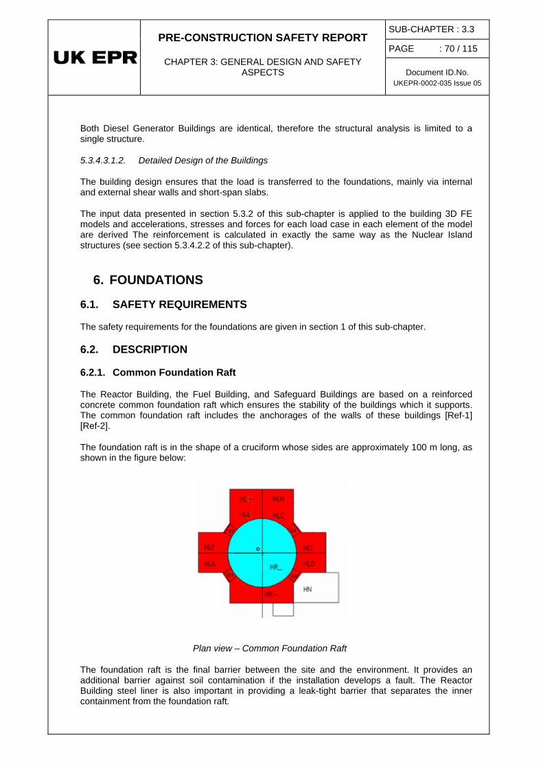
PRE-CONSTRUCTION SAFETY REPORT
CHAPTER 3: GENERAL DESIGN AND SAFETY ASPECTS
SUB-CHAPTER : 3.3 PAGE : 70 / 115
Document ID.No. UKEPR-0002-035 Issue 05
Both Diesel Generator Buildings are identical, therefore the structural analysis is limited to a single structure.
5.3.4.3.1.2. Detailed Design of the Buildings
The building design ensures that the load is transferred to the foundations, mainly via internal and external shear walls and short-span slabs.
The input data presented in section 5.3.2 of this sub-chapter is applied to the building 3D FE models and accelerations, stresses and forces for each load case in each element of the model are derived The reinforcement is calculated in exactly the same way as the Nuclear Island structures (see section 5.3.4.2.2 of this sub-chapter).
6. FOUNDATIONS
6.1. SAFETY REQUIREMENTS
The safety requirements for the foundations are given in section 1 of this sub-chapter.
6.2. DESCRIPTION
6.2.1. Common Foundation Raft
The Reactor Building, the Fuel Building, and Safeguard Buildings are based on a reinforced concrete common foundation raft which ensures the stability of the buildings which it supports. The common foundation raft includes the anchorages of the walls of these buildings [Ref-1] [Ref-2].
The foundation raft is in the shape of a cruciform whose sides are approximately 100 m long, as shown in the figure below:
Plan view – Common Foundation Raft
The foundation raft is the final barrier between the site and the environment. It provides an additional barrier against soil contamination if the installation develops a fault. The Reactor Building steel liner is also important in providing a leak-tight barrier that separates the inner containment from the foundation raft.

PRE-CONSTRUCTION SAFETY REPORT
CHAPTER 3: GENERAL DESIGN AND SAFETY ASPECTS
SUB-CHAPTER : 3.3 PAGE : 71 / 115
Document ID.No. UKEPR-0002-035 Issue 05
The common foundation raft is also equipped with an underlying membrane, protecting the structure against the groundwater table.
The prestressing gallery used for the stressing and anchorage of inner containment prestressing tendons is independent of the foundation raft. It is circular in form and situated on the underside of the raft.
The sumps and pits mean there are localised outlets in the foundation raft, mainly under the Fuel Building, on the periphery of the external containment.
6.2.2. Nuclear Auxiliary Building
The foundation of the Nuclear Auxiliary Building is comprised of reinforced concrete and is separate from the common foundation raft. This foundation raft is also waterproofed on its underside. The FA3 EPR is used as a reference example of the application of EPR design [Ref-1].
6.2.3. Diesel Generator Buildings
The foundation rafts of the Diesel Generator Buildings are independent and comprised of reinforced concrete. The FA3 EPR is used as a reference example of the application of EPR design [Ref-1].
6.2.4. Effluent Treatment Building
The foundation rafts of the two sections of the Effluent Treatment Building are connected but independent from other sub-structures. They are comprised of reinforced concrete.
6.2.5. Pumping Station
The Pumping Station stands on a substantial independent reinforced concrete foundation raft.
6.3. DESIGN BASIS
The design of the foundations is fully dependant on the site soil characteristics.
6.3.1. Design Rules and Structural Analysis
6.3.1.1. Common foundation raft
Global Finite Element Model: A global FE model is used to design the common foundation [Ref-1].
Raft detailed design: The detailed design of the common foundation raft is based upon ETC-C rules (see Sub-chapter 3.8), seismic analyses [Ref-2] and is in accordance with a specific pre-defined methodology. The design relies on criteria that ensure safe behaviour under accident conditions.
Design Rules
The uplift condition shall be taken into account in the analysis of the bearing capacity of the foundation, for both static and seismic loads [Ref-2] [Ref-3] (as described in the ETC-C).
: Soil-Structure Interaction (SSI) will be considered as a requirement of the ETC-C and seismic analyses [Ref-2] [Ref-3].

PRE-CONSTRUCTION SAFETY REPORT
CHAPTER 3: GENERAL DESIGN AND SAFETY ASPECTS
SUB-CHAPTER : 3.3 PAGE : 72 / 115
Document ID.No. UKEPR-0002-035 Issue 05
The design rules and loading scenarios described in section 5.3.1 of this sub-chapter are also applied to the common foundation raft.
Structure-Soil-Structure Interaction (SSSI) will remain outside GDA scope due to its site dependency.
The foundation raft shall meet the requirements of the buildings it supports, meeting the common requirement for their protection against groundwater leakage.
The foundation raft serviceability shall be demonstrated for loadings similar to those considered for the inner containment and the peripheral buildings.
The foundation raft integrity at the junction with the containment wall shall be ensured for the Design Basis Earthquake (DBE) + SLB LOCA and for core melt situations addressed in the safety case. For the severe accident load case the behaviour of the raft shall be carefully studied taking account of loadings such as the thermal thrust of inner structures, the shear and tensile force combined with thermal bending moments and also the tangential tensile forces for the part of the raft at the periphery of the Reactor Building (extension of the outer containment).
6.3.1.2. Independent foundation rafts
Raft detailed design: The detailed design of the independent foundation rafts is based upon the ETC-C and the specific hypothesis and calculation notes [Ref-1]. The design relies on criteria that ensure safe behaviour under accident conditions.
Design Rules
The uplift condition shall be taken into account in the analysis of the bearing capacity of the foundation, for both static and seismic loads [Ref-2] [Ref-3] (as described in the ETC-C).
: The Soil Structure Interaction shall be considered as a requirement of the ETC-C and seismic analysis results [Ref-2] [Ref-3].
The design rules and loading scenarios described in section 5.3.1 of this sub-chapter are also applied to the independent foundation raft.
6.3.2. Loads Cases and Load Combinations
The load cases and load combinations are defined in the ETC-C Part 1 (see Sub-chapter 3.8) and described in section 1 of this sub-chapter.
The common foundation raft is designed to withstand accident conditions such as the Design Basis Earthquake (DBE), an aircraft crash, core meltdown (RCC-B), explosions and/or fire and SLB LOCA + DBE.
The foundation rafts of the two Diesel Generator Buildings and of the Nuclear Auxiliary Building are designed to withstand accident conditions such as the Design Basis Earthquake (DBE).
The foundation raft of the Pumping Station is designed to withstand the Design Basis Earthquake (DBE).

PRE-CONSTRUCTION SAFETY REPORT
CHAPTER 3: GENERAL DESIGN AND SAFETY ASPECTS
SUB-CHAPTER : 3.3
PAGE : 73 / 115
Document ID.No. UKEPR-0002-035 Issue 05
SUB-CHAPTER 3.3 - TABLE 1 Design safety requirements applicable to the Reactor Building and the airplane resistant shell [from ETC-C (see Sub-chapter 3.8)]
Situations : categories and definitions
Internal containment
Internal structures
External containment Foundation
raft
Airplane resistant shell
Steel liner plate
Conduits IRWST tank
Reactor Building pool
N Reactor states A to F Reactor reactor environmental conditions
AB AB / AB / C + AM C + AM E E
E1 PCC-2 Environment AB AB / AB / C + AM C + AM E / E2 Inspection earthquake AB AB AB AB AB C + AM C + AM E E
E3 Snow and wind / / AB / AB / / / /
E4 Extreme temperatures / / AB / AB / / / /
E5 Water table / / / E / / / / / E6 Periodical tests and events AB / AB + C AB / C + AM C + AM / / A1 Earthquake RB RB RB RB RB C C E AM A2 Aircraft crash / / RB RB RB / / / / A3 Explosions / fires / / RB / RB / / / / A4 High energy piper break /
projectiles RB RB Local RB / / C RM / /
A5 PCC-3/PCC-4 and RRC-A Environment
RB RB / / / C C E /
A6 RRC-B Environment RB RB C RB / C C / / A7 2A – LOCA RB RB / RB / C C / / A8 LOCA + Earthquake RB RB / RB / C C / /
Key: characterisation of the expected function of the systems after application of the permanent, variable or accident loads A: service capability C: containment E: leak-tightness R: resistance (Suffix B: concrete wall – Suffix M: steel structure)

PRE-CONSTRUCTION SAFETY REPORT
CHAPTER 3: GENERAL DESIGN AND SAFETY ASPECTS
SUB-CHAPTER : 3.3
PAGE : 74 / 115
Document ID.No. UKEPR-0002-035 Issue 05
SUB-CHAPTER 3.3 - TABLE 2
Safety Requirements applicable to the Design of Buildings for the Nuclear Island excluding the Reactor Building and the airplane resistant shell [from ETC-C (see Sub chapter 3.8)]
Key: characterisation of the expected function of the systems after application of the permanent, variable or accident actions A: service capability C: containment (* with ventilation) (** radiological consequences limitation) E: leak-tightness (* per leak collection area) R: resistance (* partial) (Suffix B: concrete wall – Suffix M: steel structure)
Situations : categories and definitions
Bunker : Fuel Building and 2 Safeguard Building divisions
2 other Safeguard building divisions structures
Nuclear Auxiliary Building/ Effluent Treatment Building Struct. Ext
Pumping Station
Safeguard Building RIS [SIS] rooms
Safeguard Building rooms EVU [CHRS]
Diesel generator building
Drainable compartments
Non-drainable comp.
N Reactor states A to F Reactor reactor environmental conditions
AB AB AB AB / / AB E E
E1 PCC-2 Environment AB AB AB / AB / / E E
E2 Inspection earthquake AB AB AB AB AB AB AB E E
E3 Snow and wind / AB AB AB / / AB / /
E4 Extreme temperatures / AB AB AB / / AB / /
E5 Water table / / AB AB / / AB / /
A1 Earthquake RB RB RB / E* RB RB RB RB E E
A2 Aircraft crash / / / RB * RB * RB * / / /
A3 Explosions / fires / RB RB RB / / RB / /
A4 High energy pipe break / projectiles
/ / / / / / / / /
A5 PCC-3/4 and RRC-A Environment RB / C* RB / C* E* / RB / C* / / / E
A6 RRC-B Environment / / / / / RB / C* / / /

PRE-CONSTRUCTION SAFETY REPORT
CHAPTER 3: GENERAL DESIGN AND SAFETY ASPECTS
SUB-CHAPTER : 3.3
PAGE : 75 / 115
Document ID.No. UKEPR-0002-035 Issue 05
SUB-CHAPTER 3.3 - TABLE 3 Table of load combinations applicable to C1 main Structures
[from ETC-C (see Sub-chapter 3.8)]
Num
ber
Des
igna
tion
Perm
anen
t loa
ding
s
Pres
tres
sing
Varia
ble
load
ings
in
cons
truc
tion
or o
pera
ting
phas
es
Exte
rnal
tem
pera
ture
Oth
ers
( clim
atic
, wat
er
tem
pera
ture
, se
rvic
eabi
lity
eart
hqua
ke)
Inte
rnal
Exte
rnal
1 Construction X X X X X
2Normal operating conditions X X X X
3
Normal operating conditions + climatic loadings
X X X X
4Serviceability earthquake X X X X
5Ground water level X X X X
6Exceptional water temperature conditions X X X
7Exceptional climatic conditions X X X X
8 Test X X X9 LOCA X X X10 Design (0,55MPa) X X X X11 SA (0,65 Mpa) X X X X
12High Energy Pipe Rupture X X X X X
13 Internal missile X X X X
14Accidental water temperature X X X
15 DE including vibrations X X X X X
16Airplane crash including vibrations X X X X X
17 External explosion X X X X X18 Flooding X X X X X X19 LOCA +DE X X X X X X20 DE + climatic loadings X X X
Exce
ptio
nal
cond
ition
sA
ccid
enta
l co
nditi
ons
Accidental actions
Variable actions
Permanentactions
Nor
mal
cond
ition
s

PRE-CONSTRUCTION SAFETY REPORT
CHAPTER 3: GENERAL DESIGN AND SAFETY ASPECTS
SUB-CHAPTER : 3.3
PAGE : 76 / 115
Document ID.No. UKEPR-0002-035 Issue 05
SUB-CHAPTER 3.3 - TABLE 4 ETC-C Summary
Section 1: Design
• Actions and combinations of actions
• Concrete structures
• Steel components contributing to leak-tightness
• Steel Lining of pools
• Steel structures
• Anchoring of mounting panels
Appendices: seismic analysis, removal and creep, simplified procedure for assessment of military aircraft impact, nature of perforation.
Section 2: Production
• Soil, concrete, surfaces and reinforcement, tendons for reinforced concrete, prestressing
• Penetrations, liner and pool linings, pre-manufacturing, steel structures,
• Tolerances
Section 3: Instrumentation and tests
• Leak-tightness tests
• Instrumentation and resistance tests

PRE-CONSTRUCTION SAFETY REPORT
CHAPTER 3: GENERAL DESIGN AND SAFETY ASPECTS
SUB-CHAPTER : 3.3
PAGE : 77 / 115
Document ID.No. UKEPR-0002-035 Issue 05
SUB-CHAPTER 3.3 – TABLE 5 List of Penetrations - Inner Containment
System characteristics characteristics of the penetrations sleeves
in the inner containment (CIVIL ENGINEERING CONTRACTOR SUPPLY)
N°
ECS
KKS
Cod
ifica
tion
Syst
em
Func
tion
Res
pons
ible
Kind
Syst
em T
ype
Flui
d ty
pe
DN
Slop
e (%
) In
sula
tion
(mm
)
Peri.
bui
ldin
g
Cod
ifica
tion
Slee
ve ty
pe
ext d
iam
. (m
m)
Altit
. (m
)
Angl
e (d
egre
e)
1 RCV JEW EPP6001TWM Seal return FG C S W 50 1 60 FB EPP6001TWI S 273 -1,20 197 2 RCV KBA EPP6002TWM Charging FG C H.E. W 100 1 FB EPP6002TWI H.E. 323,9 -1,20 157 3 RCV KBA EPP6003TWM Letdown FG C S W 150 1 FB EPP6003TWI H.E. 323,9 -1,20 166 4 RCV JEW EPP6004TWM Seal injection FG C H.E. W 50 1 60 FB EPP6004TWI H.E. 273 -1,20 194 5 TEG KPL EPP6005TWM Gaseous waste system SY C H.E. G 50 4 FB EPP6005TWI S 273 -1,20 142 6 TEG KPL EPP6006TWM Gaseous waste system SY C H.E. G 50 4 FB EPP6006TWI S 273 -1,20 145 7 RPE KTA EPP6007TWM Coolant treatment FS C S W 80 1 FB EPP6007TWI S 273 -1,20 185 8 RPE KTC EPP6008TWM Floor drain 1 FS C S W 50 1 FB EPP6008TWI S 273 -1,20 139 9 REN KUA EPP6009TWM Sampling of loop 1&2 FS C H.E. W 8 1 50 FB EPP6009TWI H.E. 273 -1,20 191 10 REN KUA EPP6010TWM Sampling of loop 3&4 FS C H.E. W 8 1 50 FB EPP6010TWI H.E. 273 -1,20 163 11 REN KUA EPP6011TWM Sampling of pressuriser FS C H.E. W 8 1 50 FB EPP6011TWI H.E. 273 -1,20 160 12 RPE KTC EPP6012TWM Chemical drains reinjection FS C S W 50 1 FB EPP6012TWI S 273 -1,20 151 14 RPE KTD EPP6014TWM Floor drain 2 FS C S W 50 1 40 FB EPP6014TWI S 273 -1,20 148
16 PTR FAL EPP6016TWM Reactor pool transfer (upstream of pump) SY C S W 150 1 FB EPP6016TWI S 508 -1,20 188
17 PTR FAL EPP6017TWM Reactor pool transfer (downstream of pump) SY C S W 150 1 FB EPP6017TWI S 508 +2,30 182
19 APG LCQ EPP6019TWM Steam generator blowdown SY C H.E. W 150 1 60 SAB4 EPP6019TWI H.E. 508 -1,20 72 21 RBS JDH EPP6021TWM Extra boration system loop 1&2 FS C H.E. W 50 1 FB EPP6021TWI H.E. 273 +2,30 185 22 RBS JDH EPP6022TWM Extra boration system loop 3&4 FS C H.E. W 50 1 FB EPP6022TWI H.E. 273 +2,30 151

PRE-CONSTRUCTION SAFETY REPORT
CHAPTER 3: GENERAL DESIGN AND SAFETY ASPECTS
SUB-CHAPTER : 3.3
PAGE : 78 / 115
Document ID.No. UKEPR-0002-035 Issue 05
System characteristics characteristics of the penetrations sleeves
in the inner containment (CIVIL ENGINEERING CONTRACTOR SUPPLY)
N°
ECS
KKS
Cod
ifica
tion
Syst
em
Func
tion
Res
pons
ible
Kind
Syst
em T
ype
Flui
d ty
pe
DN
Slop
e (%
) In
sula
tion
(mm
)
Peri.
bui
ldin
g
Cod
ifica
tion
Slee
ve ty
pe
ext d
iam
. (m
m)
Altit
. (m
)
Angl
e (d
egre
e)
23 RES QUC EPP6023TWM Sampling SG1 secondary side FS C H.E. W 8 1 50 FB EPP6023TWI H.E. 273 +2,30 188 24 RES QUC EPP6024TWM Sampling SG2 secondary side FS C H.E. W 8 1 50 FB EPP6024TWI H.E. 273 +2,30 191 25 RES QUC EPP6025TWM Sampling SG3 secondary side FS C H.E. W 8 1 50 FB EPP6025TWI H.E. 273 +2,30 154 26 RES QUC EPP6026TWM Sampling SG4 secondary side FS C H.E. W 8 1 50 FB EPP6026TWI H.E. 273 +2,30 157 27 REN KUB EPP6027TWM Sampling of accumulators FS C H.E. W 8 1 50 FB EPP6027TWI H.E. 273 +2,30 160 30 Mechanical Reserve SY C R FB EPP6030TWI S 273 +14,45 145 31 SAT SCB EPP6031TWM Service compressed air SY C H.E. G 50 1 FB EPP6031TWI S 273 +10,80 197 32 Mechanical reserve SY C R FB EPP6032TWI S 273 +9,80 200
33 JPI SGB EPP6033TWM Water for fire protection Hydrant Reactor building SY C S W 150 1 FB EPP6033TWI S 508 +6,20 145
34 SED GHC EPP6034TWM Demineralized water SY C S W 50 1 FB EPP6034TWI S 273 +10,80 194 35 DER QNJ EPP6035TWM Chilled water for HVAC inlet SY C S W 200 0.5 50 FB EPP6035TWI S 508 +9,80 157
36 DER QNJ EPP6036TWM Chilled water for HVAC outlet SY C S W 200 0.5 50 FB EPP6036TWI S 508 +9,80 160 37 SNL EPP6037TWM SNL Reserve (sludge lancing) SY C S W 1 FB EPP6037TWI S 273 +10,80 191 38 SNL EPP6038TWM SNL Reserve (sludge lancing) SY C S W 80 1 FB EPP6038TWI S 273 +14,45 142
40 KRT EPP6040TWM Radiation monitoring system SY C S A 15 25 FB EPP6040TWI S 273 +6,20 148
41 SGN QJB EPP6041TWM N2 distribution SY C H.E. G 25 1 FB EPP6041TWI H.E. 273 +14,45 194
42 PMC FCJ EPP6042TWM Fuel transfer tube – See appendix I SY C Tube W - FB EPP6042TWI Tube 940 +7,20
44 EBA KLA EPP6044TWM Air supply KLA 3 SY C H.E. A 1000 0 FB EPP6044TWI HVAC 1016 +9,80 145 45 EBA KLA EPP6045TWM Air exhaust KLA 4 SY C H.E. A 1000 0 FB EPP6045TWI HVAC 1016 +9,80 151 46 EBA KLA EPP6046TWM Air exhaust KLA 2 SY C H.E. A 500 0 FB EPP6046TWI HVAC 508 +14,45 191

PRE-CONSTRUCTION SAFETY REPORT
CHAPTER 3: GENERAL DESIGN AND SAFETY ASPECTS
SUB-CHAPTER : 3.3
PAGE : 79 / 115
Document ID.No. UKEPR-0002-035 Issue 05
System characteristics characteristics of the penetrations sleeves
in the inner containment (CIVIL ENGINEERING CONTRACTOR SUPPLY)
N°
ECS
KKS
Cod
ifica
tion
Syst
em
Func
tion
Res
pons
ible
Kind
Syst
em T
ype
Flui
d ty
pe
DN
Slop
e (%
) In
sula
tion
(mm
)
Peri.
bui
ldin
g
Cod
ifica
tion
Slee
ve ty
pe
ext d
iam
. (m
m)
Altit
. (m
)
Angl
e (d
egre
e)
47 EBA KLA EPP6047TWM Air supply KLA 1 SY C H.E. A 500 0 FB EPP6047TWI HVAC 508 +12,80 145
48 EPP JMM EPP6048TWM Containment inflating/deflating (test line) SY C H.E. A 250 0.5 FB EPP6048TWI S 508 +14,45 197
52 EPP6052ZS Site access SY I Access A FB EPP6052TZI Access Int ø
2900 +2,60 230
53 EPP JMG EPP6053ZS Emergency airlock SY C Airlock A FB EPP6053TZI Airlock Int ø 3300 +20,60 230
54 EPP JME EPP6054ZS Equipment hatch SY C Hatch A FB EPP6054TZI Hatch Int ø 8300
+23,15 150
62 Mechanical Reserve SY C R FB EPP6062TWI S 273 +2,30 194 64 Mechanical reserve SY C R FB EPP6064TWI R 610 +20,60 200 65 Mechanical reserve SY I R Annulus EPP6065TWI S 273 +2,30 145 66 SGN QJB EPP6066TWM N2 distribution SY C H.E. G 25 FB EPP6066TWI H.E. 273 +2,30 148 67 Electrical reserve SY I ELEC. Annulus EPP6067TWI ELEC. 457 +7.40 151
68 Electrical reserve SY I ELEC. Annulus EPP6068TWI ELEC. 457 +7.40 154 69 Electrical reserve SY I ELEC. Annulus EPP6069TWI ELEC. 457 +7.40 157 75 Electrical reserve SY I ELEC. Annulus EPP6075TWI ELEC. 457 +7.40 160
76 KRT EPP6076TWM Radiation monitoring system SY C S A 15 25 FB EPP6076TWI R 273 +14.45 157
77 Mechanical reserve SY C R FB EPP6077TWI R 273 +14.45 161 78 Mechanical reserve SY C R FB EPP6078TWI R 273 +14.45 200

PRE-CONSTRUCTION SAFETY REPORT
CHAPTER 3: GENERAL DESIGN AND SAFETY ASPECTS
SUB-CHAPTER : 3.3
PAGE : 80 / 115
Document ID.No. UKEPR-0002-035 Issue 05
System characteristics characteristics of the penetrations sleeves
in the inner containment (CIVIL ENGINEERING CONTRACTOR SUPPLY)
N°
ECS
KKS
Cod
ifica
tion
Syst
em
Func
tion
Res
pons
ible
Kind
Syst
em T
ype
Flui
d ty
pe
DN
Slop
e (%
) In
sula
tion
(mm
)
Peri.
bui
ldin
g
Cod
ifica
tion
Slee
ve ty
pe
ext d
iam
. (m
m)
Altit
. (m
)
Angl
e (d
egre
e)
79 Mechanical reserve SY C R FB EPP6079TWI R 273 +10.80 200 100 RIS JNK EPP6100TWM Sump suction SIS FS C H.E. W 400 SAB1 EPP6100TWI RIS EVU 711 -6,93 280 101 RIS JNG EPP6101TWM LHSI/RHRS FS C H.E. W 200 0.5 100 SAB1 EPP6101TWI H.E. 610 -1,20 280 102 RIS JND EPP6102TWM MHSI FS C H.E. W 150 1 SAB1 EPP6102TWI H.E. 508 -1,20 276 103 RIS JNA EPP6103TWM LHSI/RHR suction line/RHR FS C H.E. W 250 0.5 SAB1 EPP6103TWI H.E. 610 -1,20 284 104 EVU JMQ EPP6104TWM Spray line SY C S W 200 2 SAB1 EPP6104TWI H.E. 610 -1,20 269 105 EVU JNK EPP6105TWM Sump suction CHRS FS C H.E. W 350 SAB1 EPP6105TWI RIS EVU 711 -7,02 248 106 ASG LAR EPP6106TWM EFWS SG1 FG C H.E. W 100 1 SAB1 EPP6106TWI H.E. 508 +3,50 263 107 RRI KAB EPP6107TWM Inlet RB ( common1) SY C S W 300 0.5 SAB1 EPP6107TWI S 508 +2,30 288 108 RRI KAB EPP6108TWM Outlet RB ( common1) SY C S W 300 0.5 SAB1 EPP6108TWI S 508 +2,30 270 109 ARE LAB EPP6109TWM Feed water line SG1 FS C S&FW W 500 1 110 SAB1 EPP6109TWI MFWL 1016 +17,80 248 110 VVP LBA EPP6110TWM Main steam line SG1 FS C S&FW S 750 2 190 SAB1 EPP6110TWI MSL 1420 +22,50 264,4 113 RRI KAB EPP6113TWM Inlet RB ( NC common1) SY C S W 200 1 SAB1 EPP6113TWI S 508 +2,30 284 114 RRI KAB EPP6114TWM Outlet RB ( NC common1) SY C S W 200 1 SAB1 EPP6114TWI S 508 +2,30 274 115 EVU JMQ EPP6115TWM Basemat cooling line SY C S W 200 2 SAB1 EPP6115TWI H.E. 610 -1,20 263 116 EVU JMQ EPP6116TWM Screen flushing line SY C S W 200 2 SAB1 EPP6116TWI H.E. 610 -1,20 266 117 RRI KAB EPP6117TWM Thermal Barrier Cooling of RCP SY C S W 80 1 SAB1 EPP6117TWI S 508 +2,30 266 118 RRI KAB EPP6118TWM Thermal Barrier Cooling of RCP SY C S W 80 1 SAB1 EPP6118TWI S 508 +2,30 280 130 EPP JML EPP6130TWO Medium voltage SY I ELEC. SAB1 EPP6130TWI ELEC. 625 +9,80 259 131 EPP JML EPP6131TWO Medium voltage SY I ELEC. SAB1 EPP6131TWI ELEC. 625 +9,80 263 132 EPP JML EPP6132TWO I&C SY I ELEC. SAB1 EPP6132TWI ELEC. 457 +11,00 259 133 EPP JML EPP6133TWO I&C SY I ELEC. SAB1 EPP6133TWI ELEC. 457 +11,00 263
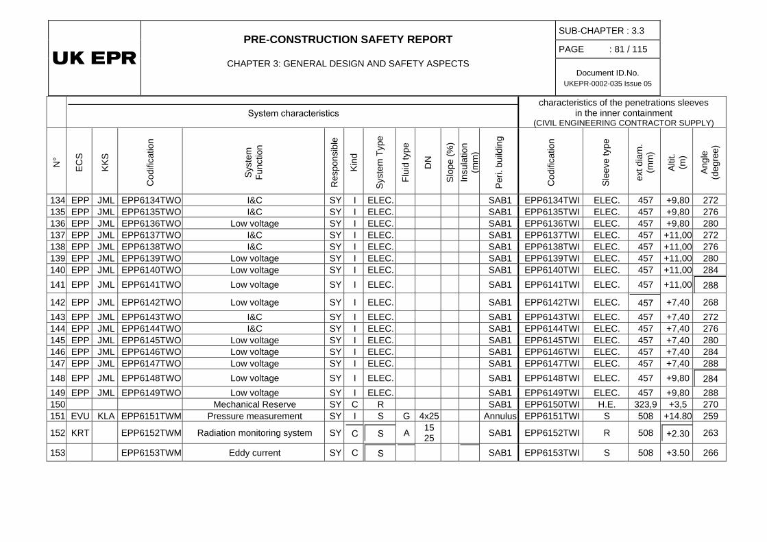
PRE-CONSTRUCTION SAFETY REPORT
CHAPTER 3: GENERAL DESIGN AND SAFETY ASPECTS
SUB-CHAPTER : 3.3
PAGE : 81 / 115
Document ID.No. UKEPR-0002-035 Issue 05
System characteristics characteristics of the penetrations sleeves
in the inner containment (CIVIL ENGINEERING CONTRACTOR SUPPLY)
N°
ECS
KKS
Cod
ifica
tion
Syst
em
Func
tion
Res
pons
ible
Kind
Syst
em T
ype
Flui
d ty
pe
DN
Slop
e (%
) In
sula
tion
(mm
)
Peri.
bui
ldin
g
Cod
ifica
tion
Slee
ve ty
pe
ext d
iam
. (m
m)
Altit
. (m
)
Angl
e (d
egre
e)
134 EPP JML EPP6134TWO I&C SY I ELEC. SAB1 EPP6134TWI ELEC. 457 +9,80 272 135 EPP JML EPP6135TWO I&C SY I ELEC. SAB1 EPP6135TWI ELEC. 457 +9,80 276 136 EPP JML EPP6136TWO Low voltage SY I ELEC. SAB1 EPP6136TWI ELEC. 457 +9,80 280 137 EPP JML EPP6137TWO I&C SY I ELEC. SAB1 EPP6137TWI ELEC. 457 +11,00 272 138 EPP JML EPP6138TWO I&C SY I ELEC. SAB1 EPP6138TWI ELEC. 457 +11,00 276 139 EPP JML EPP6139TWO Low voltage SY I ELEC. SAB1 EPP6139TWI ELEC. 457 +11,00 280 140 EPP JML EPP6140TWO Low voltage SY I ELEC. SAB1 EPP6140TWI ELEC. 457 +11,00 284 141 EPP JML EPP6141TWO Low voltage SY I ELEC. SAB1 EPP6141TWI ELEC. 457 +11,00 288
142 EPP JML EPP6142TWO Low voltage SY I ELEC. SAB1 EPP6142TWI ELEC. 457 +7,40 268 143 EPP JML EPP6143TWO I&C SY I ELEC. SAB1 EPP6143TWI ELEC. 457 +7,40 272 144 EPP JML EPP6144TWO I&C SY I ELEC. SAB1 EPP6144TWI ELEC. 457 +7,40 276 145 EPP JML EPP6145TWO Low voltage SY I ELEC. SAB1 EPP6145TWI ELEC. 457 +7,40 280 146 EPP JML EPP6146TWO Low voltage SY I ELEC. SAB1 EPP6146TWI ELEC. 457 +7,40 284 147 EPP JML EPP6147TWO Low voltage SY I ELEC. SAB1 EPP6147TWI ELEC. 457 +7,40 288 148 EPP JML EPP6148TWO Low voltage SY I ELEC. SAB1 EPP6148TWI ELEC. 457 +9,80 284 149 EPP JML EPP6149TWO Low voltage SY I ELEC. SAB1 EPP6149TWI ELEC. 457 +9,80 288 150 Mechanical Reserve SY C R SAB1 EPP6150TWI H.E. 323,9 +3,5 270 151 EVU KLA EPP6151TWM Pressure measurement SY I S G 4x25 Annulus EPP6151TWI S 508 +14.80 259
152 KRT EPP6152TWM Radiation monitoring system SY C S A 15 25 SAB1 EPP6152TWI R 508 +2.30 263
153 EPP6153TWM Eddy current SY C S SAB1 EPP6153TWI S 508 +3.50 266

PRE-CONSTRUCTION SAFETY REPORT
CHAPTER 3: GENERAL DESIGN AND SAFETY ASPECTS
SUB-CHAPTER : 3.3
PAGE : 82 / 115
Document ID.No. UKEPR-0002-035 Issue 05
System characteristics characteristics of the penetrations sleeves
in the inner containment (CIVIL ENGINEERING CONTRACTOR SUPPLY)
N°
ECS
KKS
Cod
ifica
tion
Syst
em
Func
tion
Res
pons
ible
Kind
Syst
em T
ype
Flui
d ty
pe
DN
Slop
e (%
) In
sula
tion
(mm
)
Peri.
bui
ldin
g
Cod
ifica
tion
Slee
ve ty
pe
ext d
iam
. (m
m)
Altit
. (m
)
Angl
e (d
egre
e)
200 RIS JNK EPP6200TWM Sump suction SIS FS C H.E. W 400 SAB2 EPP6200TWI RIS EVU 711 -6,93 337 201 RIS JNG EPP6201TWM LHSI/RHR FS C H.E. W 200 0.5 100 SAB2 EPP6201TWI H.E. 610 -1,20 324 202 RIS JND EPP6202TWM MHSI FS C H.E. W 150 1 SAB2 EPP6202TWI H.E. 508 -1,20 320 203 RIS JNA EPP6203TWM LHSI/RHR suction line/RHR FS C H.E. W 250 0.5 SAB2 EPP6203TWI H.E. 610 -1,20 328 204 ASG LAR EPP6204TWM EFWS SG2 FG C H.E. W 100 1 SAB2 EPP6204TWI H.E. 508 +3,50 320 205 APG LCQ EPP6205TWM Flashed steam line SY C H.E. S 300 0.5 100 SAB1 EPP6205TWI H.E. 711 +27,30 292 207 ARE LAB EPP6207TWM Feed water line SG2 FS C S&FW W 500 1 110 SAB1 EPP6207TWI MFWL 1016 +17,80 284 208 VVP LBA EPP6208TWM Main steam line SG2 FS C S&FW S 750 2 190 SAB1 EPP6208TWI MSL 1420 +22,50 275,60
211 EPP JMF EPP6211ZS Personnel airlock SY C AIRLOCK A SAB2 EPP6211TZI Airlock 3300 +2,60 0
212 JPI SGB EPP6212TWM Water for fire protection Hydrant Reactor building SY C S W 150 SAB2 EPP6212TWI R 323,9 +3,50 324
213 Mechanical reserve SY C R SAB2 EPP6213TWI R 323,9 +3,50 328 230 EPP JML EPP6230TWO Medium voltage SY I ELEC. SAB2 EPP6230TWI ELEC. 625 +9,80 320 231 EPP JML EPP6231TWO Medium voltage SY I ELEC. SAB2 EPP6231TWI ELEC. 625 +9,80 324 232 EPP JML EPP6232TWO Low voltage SY I ELEC. SAB2 EPP6232TWI ELEC. 457 +11,00 320 233 EPP JML EPP6233TWO Low voltage SY I ELEC. SAB2 EPP6233TWI ELEC. 457 +11,00 324 234 EPP JML EPP6234TWO Low voltage SY I ELEC. SAB2 EPP6234TWI ELEC. 457 +9,80 332 235 EPP JML EPP6235TWO Low voltage SY I ELEC. SAB2 EPP6235TWI ELEC. 457 +9,80 336 236 EPP JML EPP6236TWO I&C SY I ELEC. SAB2 EPP6236TWI ELEC. 457 +9,80 340 237 EPP JML EPP6237TWO I&C SY I ELEC. SAB2 EPP6237TWI ELEC. 457 +9,80 344 238 EPP JML EPP6238TWO Low voltage SY I ELEC. SAB2 EPP6238TWI ELEC. 457 +11,00 332 239 EPP JML EPP6239TWO Low voltage SY I ELEC. SAB2 EPP6239TWI ELEC. 457 +11,00 336

PRE-CONSTRUCTION SAFETY REPORT
CHAPTER 3: GENERAL DESIGN AND SAFETY ASPECTS
SUB-CHAPTER : 3.3
PAGE : 83 / 115
Document ID.No. UKEPR-0002-035 Issue 05
System characteristics characteristics of the penetrations sleeves
in the inner containment (CIVIL ENGINEERING CONTRACTOR SUPPLY)
N°
ECS
KKS
Cod
ifica
tion
Syst
em
Func
tion
Res
pons
ible
Kind
Syst
em T
ype
Flui
d ty
pe
DN
Slop
e (%
) In
sula
tion
(mm
)
Peri.
bui
ldin
g
Cod
ifica
tion
Slee
ve ty
pe
ext d
iam
. (m
m)
Altit
. (m
)
Angl
e (d
egre
e)
240 EPP JML EPP6240TWO I&C SY I ELEC. SAB2 EPP6240TWI ELEC. 457 +11,00 340 241 EPP JML EPP6241TWO I&C SY I ELEC. SAB2 EPP6241TWI ELEC. 457 +11,00 344 242 EPP JML EPP6242TWO Low voltage SY I ELEC. SAB2 EPP6242TWI ELEC. 457 +16,10 316 243 EPP JML EPP6243TWO Low voltage SY I ELEC. SAB2 EPP6243TWI ELEC. 457 +16,10 320 244 EPP JML EPP6244TWO Low voltage SY I ELEC. SAB2 EPP6244TWI ELEC. 457 +16,10 324 245 EPP JML EPP6245TWO Low voltage SY I ELEC. SAB2 EPP6245TWI ELEC. 457 +16,10 328 246 EPP JML EPP6246TWO I&C SY I ELEC. SAB2 EPP6246TWI ELEC. 457 +16,10 332 247 EPP JML EPP6247TWO I&C SY I ELEC. SAB2 EPP6247TWI ELEC. 457 +16,10 336 248 EPP JML EPP6248TWO I&C SY I ELEC. SAB2 EPP6248TWI ELEC. 457 +16,10 340 249 EPP JML EPP6249TWO I&C SY I ELEC. SAB2 EPP6249TWI ELEC. 457 +16,10 344 250 Mechanical Reserve SY I R Annulus EPP6250TWI R 508 +22.50 344 300 RIS JNK EPP6300TWM Sump suction SIS FS C H.E. W 400 SAB3 EPP6300TWI RIS EVU 711 -6,93 23 301 RIS JNG EPP6301TWM LHSI/RHR FS C H.E. W 200 0.5 100 SAB3 EPP6301TWI H.E. 610 -1,20 36 302 RIS JND EPP6302TWM MHSI FS C H.E. W 150 1 SAB3 EPP6302TWI H.E. 508 -1,20 40 303 ASG LAR EPP6303TWM EFWS SG3 FG C H.E. W 100 1 SAB3 EPP6303TWI H.E. 508 +3,50 40
304 APG LCA EPP6304TWM Condensate extraction system inlet SY C H.E. W 150 1 80 SAB1 EPP6304TWI H.E. 508 +27,30 284
305 APG LCA EPP6305TWM Condensate extraction system outlet SY C H.E. W 150 1 80 SAB1 EPP6305TWI H.E. 508 +27,30 288
306 ARE LAB EPP6306TWM Feed water line SG3 FS C S&FW W 500 1 110 SAB4 EPP6306TWI MFWL 1016 +17,80 76 307 VVP LBA EPP6307TWM Main steam line SG3 FS C S&FW S 750 1 190 SAB4 EPP6307TWI MSL 1420 +22,50 84,40 308 RIS JNA EPP6308TWM LHSI/RHR suction line/RHR FS C H.E. W 250 0.5 SAB3 EPP6308TWI H.E. 610 -1,20 32 312 EPP JMM EPP6312TWM Pressure measurement SY C H.E. A 15 SAB2 EPP6312TWI S 273 +17,80 16

PRE-CONSTRUCTION SAFETY REPORT
CHAPTER 3: GENERAL DESIGN AND SAFETY ASPECTS
SUB-CHAPTER : 3.3
PAGE : 84 / 115
Document ID.No. UKEPR-0002-035 Issue 05
System characteristics characteristics of the penetrations sleeves
in the inner containment (CIVIL ENGINEERING CONTRACTOR SUPPLY)
N°
ECS
KKS
Cod
ifica
tion
Syst
em
Func
tion
Res
pons
ible
Kind
Syst
em T
ype
Flui
d ty
pe
DN
Slop
e (%
) In
sula
tion
(mm
)
Peri.
bui
ldin
g
Cod
ifica
tion
Slee
ve ty
pe
ext d
iam
. (m
m)
Altit
. (m
)
Angl
e (d
egre
e)
313 Mechanical reserve C R SAB3 EPP6313TWI R 323,9 +3,50 32 314 Mechanical reserve C R SAB3 EPP6314TWI R 323,9 +3,50 36 330 EPP JML EPP6330TWO Medium voltage SY I ELEC. SAB3 EPP6330TWI ELEC. 625 +9,80 36 331 EPP JML EPP6331TWO Medium voltage SY I ELEC. SAB3 EPP6331TWI ELEC. 625 +9,80 40 332 EPP JML EPP6332TWO Low voltage SY I ELEC. SAB3 EPP6332TWI ELEC. 457 +11,00 36 333 EPP JML EPP6333TWO Low voltage SY I ELEC. SAB3 EPP6333TWI ELEC. 457 +11,00 40 334 EPP JML EPP6334TWO Low voltage SY I ELEC. SAB3 EPP6334TWI ELEC. 457 +9,80 28 335 EPP JML EPP6335TWO Low voltage SY I ELEC. SAB3 EPP6335TWI ELEC. 457 +9,80 24 336 EPP JML EPP6336TWO Low voltage SY I ELEC. SAB3 EPP6336TWI ELEC. 457 +9,80 20 337 EPP JML EPP6337TWO I&C SY I ELEC. SAB3 EPP6337TWI ELEC. 457 +9,80 16 338 EPP JML EPP6338TWO Low voltage SY I ELEC. SAB3 EPP6338TWI ELEC. 457 +11,00 28 339 EPP JML EPP6339TWO Low voltage SY I ELEC. SAB3 EPP6339TWI ELEC. 457 +11,00 24 340 EPP JML EPP6340TWO I&C SY I ELEC. SAB3 EPP6340TWI ELEC. 457 +11,00 20 341 EPP JML EPP6341TWO I&C SY I ELEC. SAB3 EPP6341TWI ELEC. 457 +11,00 16 342 EPP JML EPP6342TWO Low voltage SY I ELEC. SAB3 EPP6342TWI ELEC. 457 +16,10 44 343 EPP JML EPP6343TWO Low voltage SY I ELEC. SAB3 EPP6343TWI ELEC. 457 +16,10 40 344 EPP JML EPP6344TWO Low voltage SY I ELEC. SAB3 EPP6344TWI ELEC. 457 +16,10 36 345 EPP JML EPP6345TWO Low voltage SY I ELEC. SAB3 EPP6345TWI ELEC. 457 +16,10 32 346 EPP JML EPP6346TWO I&C SY I ELEC. SAB3 EPP6346TWI ELEC. 457 +16,10 28 347 EPP JML EPP6347TWO I&C SY I ELEC. SAB3 EPP6347TWI ELEC. 457 +16,10 24 348 EPP JML EPP6348TWO I&C SY I ELEC. SAB3 EPP6348TWI ELEC. 457 +16,10 20 349 EPP JML EPP6349TWO I&C SY I ELEC. SAB3 EPP6349TWI ELEC. 457 +16,10 16 350 Mechanical Reserve SY I R G 3x25 Annulus EPP6350TWI S 508 +22.50 16

PRE-CONSTRUCTION SAFETY REPORT
CHAPTER 3: GENERAL DESIGN AND SAFETY ASPECTS
SUB-CHAPTER : 3.3
PAGE : 85 / 115
Document ID.No. UKEPR-0002-035 Issue 05
System characteristics characteristics of the penetrations sleeves
in the inner containment (CIVIL ENGINEERING CONTRACTOR SUPPLY)
N°
ECS
KKS
Cod
ifica
tion
Syst
em
Func
tion
Res
pons
ible
Kind
Syst
em T
ype
Flui
d ty
pe
DN
Slop
e (%
) In
sula
tion
(mm
)
Peri.
bui
ldin
g
Cod
ifica
tion
Slee
ve ty
pe
ext d
iam
. (m
m)
Altit
. (m
)
Angl
e (d
egre
e)
400 RIS JNK EPP6400TWM Sump suction SIS FS C H.E. W 400 SAB4 EPP6400TWI RIS EVU 711 -6,93 80 401 RIS JNG EPP6401TWM LHSI/RHR FS C H.E. W 200 1 100 SAB4 EPP6401TWI H.E. 610 -1,20 80 402 RIS JND EPP6402TWM MHSI FS C H.E. W 150 1 SAB4 EPP6402TWI H.E. 508 -1,20 84 403 RIS JNA EPP6403TWM LHSI/RHR suction line/RHR FS C H.E. W 250 0.5 SAB4 EPP6403TWI H.E. 610 -1,20 76 404 EVU JMQ EPP6404TWM Spray line SY C S W 200 2 SAB4 EPP6404TWI H.E. 610 -1,20 91 405 RIS JNK EPP6405TWM Sump suction CHRS FS C H.E. W 350 SAB4 EPP6405TWI RIS EVU 711 -7,02 112 406 ASG LAR EPP6406TWM EFWS SG4 FG C H.E. W 100 1 SAB4 EPP6406TWI H.E. 508 +3,50 97 407 RRI KAB EPP6407TWM Inlet RB common 2 SY C S W 300 0.5 SAB4 EPP6407TWI S 508 +2,30 72 408 RRI KAB EPP6408TWM Outlet RB Common 2 SY C S W 300 0.5 SAB4 EPP6408TWI S 508 +2,30 90 409 ARE LAB EPP6409TWM Feed water line SG4 FS C S&FW W 500 1 110 SAB4 EPP6409TWI MFWL 1016 +17,80 112 410 VVP LBA EPP6410TWM Main teams line SG4 FS C S&FW S 750 2 190 SAB4 EPP6410TWI MSL 1420 +22,50 95,60 413 EVU JMQ EPP6413TWM Basemat cooling line SY C S W 200 0.5 SAB4 EPP6413TWI H.E. 610 -1,20 97 419 EVU JMQ EPP6419TWM Screen flushing line SY C S W 200 1 SAB4 EPP6419TWI H.E. 610 -1,20 94 420 RRI KAB EPP6420TWM Thermal Barrier Cooling of RCP SY C S W 80 1 SAB4 EPP6420TWI S 508 +2,30 76 421 RRI KAB EPP6421TWM Thermal Barrier Cooling of RCP SY C S W 80 1 SAB4 EPP6421TWI S 508 +2,30 80 430 EPP JML EPP6430TWO Medium voltage SY I ELEC. SAB4 EPP6430TWI ELEC. 625 +9,80 93 431 EPP JML EPP6431TWO Medium voltage SY I ELEC. SAB4 EPP6431TWI ELEC. 625 +9,80 97 432 EPP JML EPP6432TWO I&C SY I ELEC. SAB4 EPP6432TWI ELEC. 457 +11,00 93 433 EPP JML EPP6433TWO I&C SY I ELEC. SAB4 EPP6433TWI ELEC. 457 +11,00 97 434 EPP JML EPP6434TWO I&C SY I ELEC. SAB4 EPP6434TWI ELEC. 457 +9,80 88 435 EPP JML EPP6435TWO I&C SY I ELEC. SAB4 EPP6435TWI ELEC. 457 +9,80 84 436 EPP JML EPP6436TWO I&C SY I ELEC. SAB4 EPP6436TWI ELEC. 457 +9,80 80 437 EPP JML EPP6437TWO Low voltage SY I ELEC. SAB4 EPP6437TWI ELEC. 457 +9,80 76
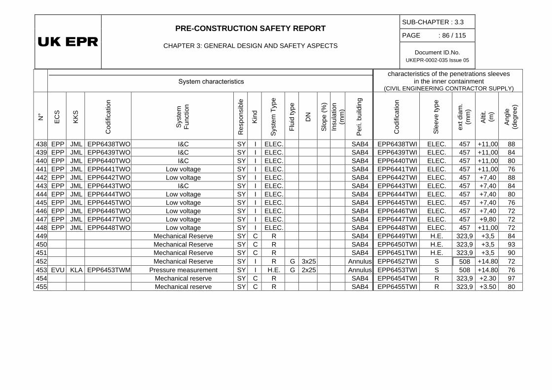
PRE-CONSTRUCTION SAFETY REPORT
CHAPTER 3: GENERAL DESIGN AND SAFETY ASPECTS
SUB-CHAPTER : 3.3
PAGE : 86 / 115
Document ID.No. UKEPR-0002-035 Issue 05
System characteristics characteristics of the penetrations sleeves
in the inner containment (CIVIL ENGINEERING CONTRACTOR SUPPLY)
N°
ECS
KKS
Cod
ifica
tion
Syst
em
Func
tion
Res
pons
ible
Kind
Syst
em T
ype
Flui
d ty
pe
DN
Slop
e (%
) In
sula
tion
(mm
)
Peri.
bui
ldin
g
Cod
ifica
tion
Slee
ve ty
pe
ext d
iam
. (m
m)
Altit
. (m
)
Angl
e (d
egre
e)
438 EPP JML EPP6438TWO I&C SY I ELEC. SAB4 EPP6438TWI ELEC. 457 +11,00 88 439 EPP JML EPP6439TWO I&C SY I ELEC. SAB4 EPP6439TWI ELEC. 457 +11,00 84 440 EPP JML EPP6440TWO I&C SY I ELEC. SAB4 EPP6440TWI ELEC. 457 +11,00 80 441 EPP JML EPP6441TWO Low voltage SY I ELEC. SAB4 EPP6441TWI ELEC. 457 +11,00 76 442 EPP JML EPP6442TWO Low voltage SY I ELEC. SAB4 EPP6442TWI ELEC. 457 +7,40 88 443 EPP JML EPP6443TWO I&C SY I ELEC. SAB4 EPP6443TWI ELEC. 457 +7,40 84 444 EPP JML EPP6444TWO Low voltage SY I ELEC. SAB4 EPP6444TWI ELEC. 457 +7,40 80 445 EPP JML EPP6445TWO Low voltage SY I ELEC. SAB4 EPP6445TWI ELEC. 457 +7,40 76 446 EPP JML EPP6446TWO Low voltage SY I ELEC. SAB4 EPP6446TWI ELEC. 457 +7,40 72 447 EPP JML EPP6447TWO Low voltage SY I ELEC. SAB4 EPP6447TWI ELEC. 457 +9,80 72 448 EPP JML EPP6448TWO Low voltage SY I ELEC. SAB4 EPP6448TWI ELEC. 457 +11,00 72 449 Mechanical Reserve SY C R SAB4 EPP6449TWI H.E. 323,9 +3,5 84 450 Mechanical Reserve SY C R SAB4 EPP6450TWI H.E. 323,9 +3,5 93 451 Mechanical Reserve SY C R SAB4 EPP6451TWI H.E. 323,9 +3,5 90 452 Mechanical Reserve SY I R G 3x25 Annulus EPP6452TWI S 508 +14.80 72 453 EVU KLA EPP6453TWM Pressure measurement SY I H.E. G 2x25 Annulus EPP6453TWI S 508 +14.80 76 454 Mechanical reserve SY C R SAB4 EPP6454TWI R 323,9 +2.30 97 455 Mechanical reserve SY C R SAB4 EPP6455TWI R 323,9 +3.50 80

PRE-CONSTRUCTION SAFETY REPORT
CHAPTER 3: GENERAL DESIGN AND SAFETY ASPECTS
SUB-CHAPTER : 3.3
PAGE : 87 / 115
Document ID.No. UKEPR-0002-035 Issue 05
SUB-CHAPTER 3.3 – TABLE 6 List of Penetrations - Outer Containment
System characteristics Characteristics of the penetration sleeves
in the outer containment (CIVIL ENGINEERING CONTRACTOR SUPPLY)
N°
ECS
KKS
Func
tion
Kind
Syst
em T
ype
Flui
de
type
DN
Slop
e (%
)
Insu
latio
n th
ickn
ess
Perip
hera
l bu
ildin
g
Cod
ifica
tion
Ext S
leev
e di
am. (
mm
)
Con
cret
e th
ickn
ess
(mm
)
Slee
ve T
ype
Altit
. (m
)
Angl
e (d
egre
e)
1 RCV JEW Seal return C S W 50 1 60 FB EPP6001TWX 508 1300 S -1,20 197 2 RCV KBA Charging C H.E. W 100 1 FB EPP6002TWX 711 1300 S -1,20 157 3 RCV KBA Letdown C S W 150 1 FB EPP6003TWX 711 1300 S -1,20 166 4 RCV JEW Seal injection C H.E. W 50 1 60 FB EPP6004TWX 508 1300 S -1,20 194 5 TEG KPL Gaseous waste system C H.E. G 50 4 FB EPP6005TWX 711 1300 S -1,20 142 6 TEG KPL Gaseous waste system C H.E. G 50 4 FB EPP6006TWX 711 1300 S -1,20 145 7 RPE KTA Coolant treatment C S W 80 1 FB EPP6007TWX 508 1300 S -1,20 185 8 RPE KTC Floor drain 1 C S W 50 1 FB EPP6008TWX 508 1300 S -1,20 139 9 REN KUA Sampling of loop 1&2 C H.E. W 8 1 50 FB EPP6009TWX 508 1300 S -1,20 191 10 REN KUA Sampling of loop 3&4 C H.E. W 8 1 50 FB EPP6010TWX 508 1300 S -1,20 163 11 REN KUA Sampling of pressuriser C H.E. W 8 1 50 FB EPP6011TWX 508 1300 S -1,20 160 12 RPE KTC Chemical drains reinjection C S W 50 1 FB EPP6012TWX 323.9 1300 S -1,20 151 14 RPE KTD Floor drain 2 C S W 50 1 40 FB EPP6014TWX 508 1300 S -1,20 148
16 PTR FAL Reactor pool transfer (upstream of pump) C S W 150 1 FB EPP6016TWX 508 1300 S -1,20 188
17 PTR FAL Reactor pool transfer (downstream of pump) C S W 150 1 FB EPP6017TWX 508 1300 S +2,30 182
19 APG LCQ Steam generator blowdown C H.E. W 150 1 60 SAB4 EPP6019TWX 711 1300 S -1,20 72
21 RBS JDH Extra boration system loop 1&2 C H.E. W 50 1 FB EPP6021TWX 406 1300 S +2,30 185
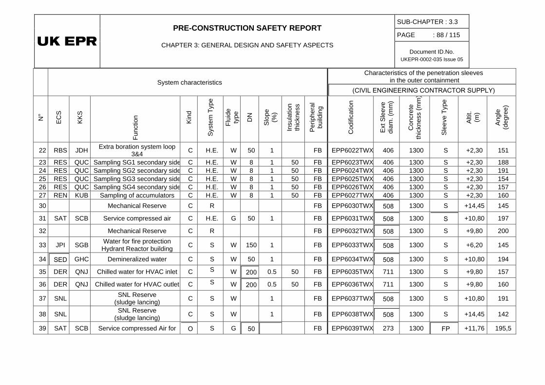
PRE-CONSTRUCTION SAFETY REPORT
CHAPTER 3: GENERAL DESIGN AND SAFETY ASPECTS
SUB-CHAPTER : 3.3
PAGE : 88 / 115
Document ID.No. UKEPR-0002-035 Issue 05
System characteristics Characteristics of the penetration sleeves
in the outer containment (CIVIL ENGINEERING CONTRACTOR SUPPLY)
N°
ECS
KKS
Func
tion
Kind
Syst
em T
ype
Flui
de
type
DN
Slop
e (%
)
Insu
latio
n th
ickn
ess
Perip
hera
l bu
ildin
g
Cod
ifica
tion
Ext S
leev
e di
am. (
mm
)
Con
cret
e th
ickn
ess
(mm
)
Slee
ve T
ype
Altit
. (m
)
Angl
e (d
egre
e)
22 RBS JDH Extra boration system loop 3&4 C H.E. W 50 1 FB EPP6022TWX 406 1300 S +2,30 151
23 RES QUC Sampling SG1 secondary side C H.E. W 8 1 50 FB EPP6023TWX 406 1300 S +2,30 188 24 RES QUC Sampling SG2 secondary side C H.E. W 8 1 50 FB EPP6024TWX 406 1300 S +2,30 191 25 RES QUC Sampling SG3 secondary side C H.E. W 8 1 50 FB EPP6025TWX 406 1300 S +2,30 154 26 RES QUC Sampling SG4 secondary side C H.E. W 8 1 50 FB EPP6026TWX 406 1300 S +2,30 157 27 REN KUB Sampling of accumulators C H.E. W 8 1 50 FB EPP6027TWX 406 1300 S +2,30 160 30 Mechanical Reserve C R FB EPP6030TWX 508 1300 S +14,45 145
31 SAT SCB Service compressed air C H.E. G 50 1 FB EPP6031TWX 508 1300 S +10,80 197
32 Mechanical Reserve C R FB EPP6032TWX 508 1300 S +9,80 200
33 JPI SGB Water for fire protection Hydrant Reactor building C S W 150 1 FB EPP6033TWX 508 1300 S +6,20 145
34 SED GHC Demineralized water C S W 50 1 FB EPP6034TWX 508 1300 S +10,80 194
35 DER QNJ Chilled water for HVAC inlet C S W 200 0.5 50 FB EPP6035TWX 711 1300 S +9,80 157
36 DER QNJ Chilled water for HVAC outlet C S W 200 0.5 50 FB EPP6036TWX 711 1300 S +9,80 160
37 SNL SNL Reserve (sludge lancing) C S W 1 FB EPP6037TWX 508 1300 S +10,80 191
38 SNL SNL Reserve (sludge lancing) C S W 1 FB EPP6038TWX 508 1300 S +14,45 142
39 SAT SCB Service compressed Air for O S G 50 FB EPP6039TWX 273 1300 FP +11,76 195,5
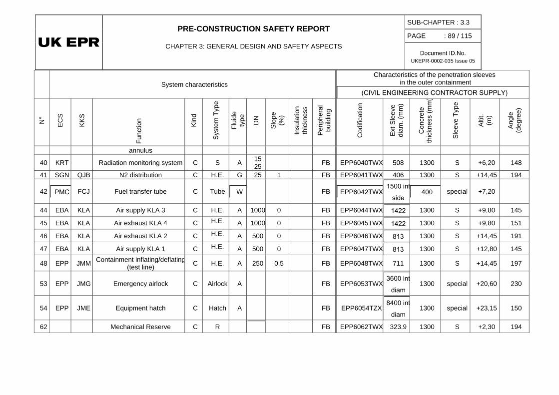
PRE-CONSTRUCTION SAFETY REPORT
CHAPTER 3: GENERAL DESIGN AND SAFETY ASPECTS
SUB-CHAPTER : 3.3
PAGE : 89 / 115
Document ID.No. UKEPR-0002-035 Issue 05
System characteristics Characteristics of the penetration sleeves
in the outer containment (CIVIL ENGINEERING CONTRACTOR SUPPLY)
N°
ECS
KKS
Func
tion
Kind
Syst
em T
ype
Flui
de
type
DN
Slop
e (%
)
Insu
latio
n th
ickn
ess
Perip
hera
l bu
ildin
g
Cod
ifica
tion
Ext S
leev
e di
am. (
mm
)
Con
cret
e th
ickn
ess
(mm
)
Slee
ve T
ype
Altit
. (m
)
Angl
e (d
egre
e)
annulus
40 KRT Radiation monitoring system C S A 15 25 FB EPP6040TWX 508 1300 S +6,20 148
41 SGN QJB N2 distribution C H.E. G 25 1 FB EPP6041TWX 406 1300 S +14,45 194
42 PMC FCJ Fuel transfer tube C Tube W FB EPP6042TWX 1500 int
side 400 special +7,20
44 EBA KLA Air supply KLA 3 C H.E. A 1000 0 FB EPP6044TWX 1422 1300 S +9,80 145
45 EBA KLA Air exhaust KLA 4 C H.E. A 1000 0 FB EPP6045TWX 1422 1300 S +9,80 151
46 EBA KLA Air exhaust KLA 2 C H.E. A 500 0 FB EPP6046TWX 813 1300 S +14,45 191
47 EBA KLA Air supply KLA 1 C H.E. A 500 0 FB EPP6047TWX 813 1300 S +12,80 145
48 EPP JMM Containment inflating/deflating (test line) C H.E. A 250 0.5 FB EPP6048TWX 711 1300 S +14,45 197
53 EPP JMG Emergency airlock C Airlock A FB EPP6053TWX 3600 int
diam 1300 special +20,60 230
54 EPP JME Equipment hatch C Hatch A FB EPP6054TZX 8400 int
diam 1300 special +23,15 150
62 Mechanical Reserve C R FB EPP6062TWX 323.9 1300 S +2,30 194
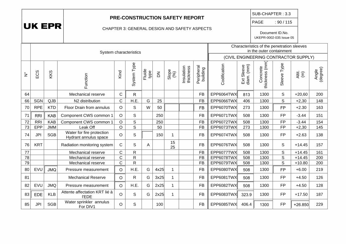
PRE-CONSTRUCTION SAFETY REPORT
CHAPTER 3: GENERAL DESIGN AND SAFETY ASPECTS
SUB-CHAPTER : 3.3
PAGE : 90 / 115
Document ID.No. UKEPR-0002-035 Issue 05
System characteristics Characteristics of the penetration sleeves
in the outer containment (CIVIL ENGINEERING CONTRACTOR SUPPLY)
N°
ECS
KKS
Func
tion
Kind
Syst
em T
ype
Flui
de
type
DN
Slop
e (%
)
Insu
latio
n th
ickn
ess
Perip
hera
l bu
ildin
g
Cod
ifica
tion
Ext S
leev
e di
am. (
mm
)
Con
cret
e th
ickn
ess
(mm
)
Slee
ve T
ype
Altit
. (m
)
Angl
e (d
egre
e)
64 Mechanical reserve C R FB EPP6064TWX 813 1300 S +20,60 200 66 SGN QJB N2 distribution C H.E. G 25 FB EPP6066TWX 406 1300 S +2,30 148 70 RPE KTD Floor Drain from annulus O S W 50 FB EPP6070TWX 273 1300 FP +2.30 163
71 RRI KAB Component CWS common 1 O S 250 FB EPP6071TWX 508 1300 FP -3.44 151 72 RRI KAB Component CWS common 1 O S 250 FB EPP6072TWX 508 1300 FP -3.44 154 73 EPP JMM Leak Off O S 50 FB EPP6073TWX 273 1300 FP +2,30 145
74 JPI SGB Water for fire protection Hydrant annulus space O S 150 1 FB EPP6074TWX 508 1300 FP +2.63 138
76 KRT Radiation monitoring system C S A 15 25 FB EPP6076TWX 508 1300 S +14.45 157
77 Mechanical reserve C R FB EPP6077TWX 508 1300 S +14.45 161 78 Mechanical reserve C R FB EPP6078TWX 508 1300 S +14.45 200 79 Mechanical reserve C R FB EPP6079TWX 508 1300 S +10.80 200 80 EVU JMQ Pressure measurement O H.E. G 4x25 1 FB EPP6080TWX 508 1300 FP +6.00 219
81 Mechanical Reserve O R G 3x25 1 FB EPP6081TWX 508 1300 FP +4.50 126
82 EVU JMQ Pressure measurement O H.E. G 2x25 1 FB EPP6082TWX 508 1300 FP +4.50 128
83 EDE KLB Attente affectation KRT lié à l'EDE O S G 2x25 1 FB EPP6083TWX 323.9 1300 FP +17.50 187
85 JPI SGB Water sprinkler annulus For DIV1 O S 100 FB EPP6085TWX 406.4 1300 FP +26.850 229

PRE-CONSTRUCTION SAFETY REPORT
CHAPTER 3: GENERAL DESIGN AND SAFETY ASPECTS
SUB-CHAPTER : 3.3
PAGE : 91 / 115
Document ID.No. UKEPR-0002-035 Issue 05
System characteristics Characteristics of the penetration sleeves
in the outer containment (CIVIL ENGINEERING CONTRACTOR SUPPLY)
N°
ECS
KKS
Func
tion
Kind
Syst
em T
ype
Flui
de
type
DN
Slop
e (%
)
Insu
latio
n th
ickn
ess
Perip
hera
l bu
ildin
g
Cod
ifica
tion
Ext S
leev
e di
am. (
mm
)
Con
cret
e th
ickn
ess
(mm
)
Slee
ve T
ype
Altit
. (m
)
Angl
e (d
egre
e)
100 RIS JNK Sump suction SIS C H.E. W 400 SAB1 EPP6100TWX 711 gusset special -6.96 280 101 RIS JNG LHSI/RHRS C H.E. W 200 0.5 100 SAB1 EPP6101TWX 813 1300 S -1,20 280 102 RIS JND MHSI C H.E. W 150 1 SAB1 EPP6102TWX 711 1300 S -1,20 276 103 RIS JNA LHSI/RHR suction line/RHR C H.E. W 250 0.5 SAB1 EPP6103TWX 813 1300 S -1,20 284 104 EVU JMQ Spray line C S W 200 2 SAB1 EPP6104TWX 813 1300 S -1,20 269 105 RIS JNK Sump suction CHRS C H.E. W 350 SAB1 EPP6105TWX 711 gusset special -7.05 248
106 ASG LAR EFWS SG1 C H.E. W 100 1 SAB1 EPP6106TWX 813 1300 S +3,50 263 107 RRI KAB Inlet RB ( common1) C S W 300 0.5 SAB1 EPP6107TWX 508 1300 S +2,30 288 108 RRI KAB Outlet RB ( common1) C S W 300 0.5 SAB1 EPP6108TWX 508 1300 S +2,30 270 109 ARE LAB Feed water line SG1 C S&FW W 500 1 110 SAB1 EPP6109TWX 1422 1800 S +17,80 248 110 VVP LBA Main steam line SG1 C S&FW S 750 2 190 SAB1 EPP6110TWX 1727 1800 special +22,50 264,4 113 RRI KAB Inlet RB ( NC common1) C S W 200 1 SAB1 EPP6113TWX 508 1300 S +2,30 284 114 RRI KAB Outlet RB ( NC common1) C S W 200 1 SAB1 EPP6114TWX 508 1300 S +2,30 274 115 EVU JMQ Basemat cooling line C S W 200 2 SAB1 EPP6115TWX 813 1300 S -1,20 263
116 EVU JMQ Screen flushing line C S W 200 2 SAB1 EPP6116TWX 813 1300 S -1,20 266
117 RRI KAB Thermal Barrier Cooling of RCP C S W 80 1 SAB1 EPP6117TWX 508 1300 S +2,30 266
118 RRI KAB Thermal Barrier Cooling of RCP C S W 80 1 SAB1 EPP6118TWX 508 1300 S +2,30 280
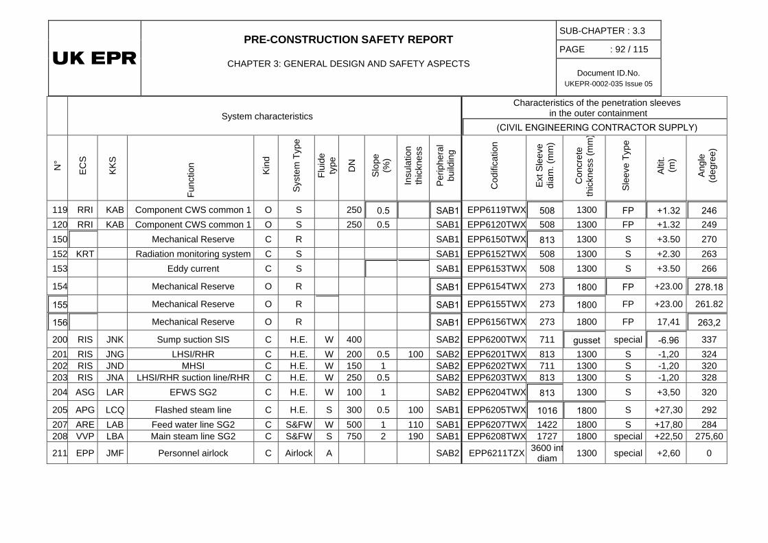
PRE-CONSTRUCTION SAFETY REPORT
CHAPTER 3: GENERAL DESIGN AND SAFETY ASPECTS
SUB-CHAPTER : 3.3
PAGE : 92 / 115
Document ID.No. UKEPR-0002-035 Issue 05
System characteristics Characteristics of the penetration sleeves
in the outer containment (CIVIL ENGINEERING CONTRACTOR SUPPLY)
N°
ECS
KKS
Func
tion
Kind
Syst
em T
ype
Flui
de
type
DN
Slop
e (%
)
Insu
latio
n th
ickn
ess
Perip
hera
l bu
ildin
g
Cod
ifica
tion
Ext S
leev
e di
am. (
mm
)
Con
cret
e th
ickn
ess
(mm
)
Slee
ve T
ype
Altit
. (m
)
Angl
e (d
egre
e)
119 RRI KAB Component CWS common 1 O S 250 0.5 SAB1 EPP6119TWX 508 1300 FP +1.32 246 120 RRI KAB Component CWS common 1 O S 250 0.5 SAB1 EPP6120TWX 508 1300 FP +1.32 249 150 Mechanical Reserve C R SAB1 EPP6150TWX 813 1300 S +3.50 270 152 KRT Radiation monitoring system C S SAB1 EPP6152TWX 508 1300 S +2.30 263 153 Eddy current C S SAB1 EPP6153TWX 508 1300 S +3.50 266
154 Mechanical Reserve O R SAB1 EPP6154TWX 273 1800 FP +23.00 278.18
155 Mechanical Reserve O R SAB1 EPP6155TWX 273 1800 FP +23.00 261.82
156 Mechanical Reserve O R SAB1 EPP6156TWX 273 1800 FP 17,41 263,2
200 RIS JNK Sump suction SIS C H.E. W 400 SAB2 EPP6200TWX 711 gusset special -6.96 337 201 RIS JNG LHSI/RHR C H.E. W 200 0.5 100 SAB2 EPP6201TWX 813 1300 S -1,20 324 202 RIS JND MHSI C H.E. W 150 1 SAB2 EPP6202TWX 711 1300 S -1,20 320 203 RIS JNA LHSI/RHR suction line/RHR C H.E. W 250 0.5 SAB2 EPP6203TWX 813 1300 S -1,20 328 204 ASG LAR EFWS SG2 C H.E. W 100 1 SAB2 EPP6204TWX 813 1300 S +3,50 320
205 APG LCQ Flashed steam line C H.E. S 300 0.5 100 SAB1 EPP6205TWX 1016 1800 S +27,30 292 207 ARE LAB Feed water line SG2 C S&FW W 500 1 110 SAB1 EPP6207TWX 1422 1800 S +17,80 284 208 VVP LBA Main steam line SG2 C S&FW S 750 2 190 SAB1 EPP6208TWX 1727 1800 special +22,50 275,60
211 EPP JMF Personnel airlock C Airlock A SAB2 EPP6211TZX 3600 int diam 1300 special +2,60 0
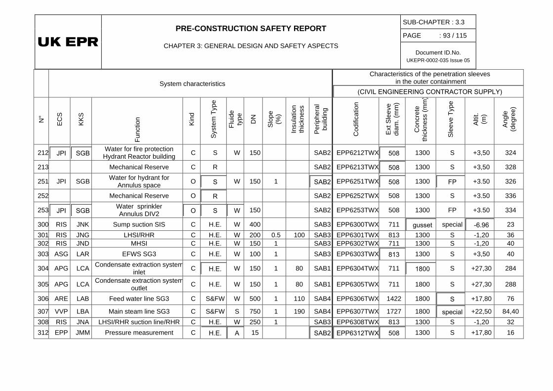
PRE-CONSTRUCTION SAFETY REPORT
CHAPTER 3: GENERAL DESIGN AND SAFETY ASPECTS
SUB-CHAPTER : 3.3
PAGE : 93 / 115
Document ID.No. UKEPR-0002-035 Issue 05
System characteristics Characteristics of the penetration sleeves
in the outer containment (CIVIL ENGINEERING CONTRACTOR SUPPLY)
N°
ECS
KKS
Func
tion
Kind
Syst
em T
ype
Flui
de
type
DN
Slop
e (%
)
Insu
latio
n th
ickn
ess
Perip
hera
l bu
ildin
g
Cod
ifica
tion
Ext S
leev
e di
am. (
mm
)
Con
cret
e th
ickn
ess
(mm
)
Slee
ve T
ype
Altit
. (m
)
Angl
e (d
egre
e)
212 JPI SGB Water for fire protection Hydrant Reactor building C S W 150 SAB2 EPP6212TWX 508 1300 S +3,50 324
213 Mechanical Reserve C R SAB2 EPP6213TWX 508 1300 S +3,50 328
251 JPI SGB Water for hydrant for Annulus space O S W 150 1 SAB2 EPP6251TWX 508 1300 FP +3.50 326
252 Mechanical Reserve O R SAB2 EPP6252TWX 508 1300 S +3.50 336
253 JPI SGB Water sprinkler Annulus DIV2 O S W 150 SAB2 EPP6253TWX 508 1300 FP +3.50 334
300 RIS JNK Sump suction SIS C H.E. W 400 SAB3 EPP6300TWX 711 gusset special -6.96 23 301 RIS JNG LHSI/RHR C H.E. W 200 0.5 100 SAB3 EPP6301TWX 813 1300 S -1,20 36 302 RIS JND MHSI C H.E. W 150 1 SAB3 EPP6302TWX 711 1300 S -1,20 40 303 ASG LAR EFWS SG3 C H.E. W 100 1 SAB3 EPP6303TWX 813 1300 S +3,50 40
304 APG LCA Condensate extraction system inlet C H.E. W 150 1 80 SAB1 EPP6304TWX 711 1800 S +27,30 284
305 APG LCA Condensate extraction system outlet C H.E. W 150 1 80 SAB1 EPP6305TWX 711 1800 S +27,30 288
306 ARE LAB Feed water line SG3 C S&FW W 500 1 110 SAB4 EPP6306TWX 1422 1800 S +17,80 76
307 VVP LBA Main steam line SG3 C S&FW S 750 1 190 SAB4 EPP6307TWX 1727 1800 special +22,50 84,40 308 RIS JNA LHSI/RHR suction line/RHR C H.E. W 250 1 SAB3 EPP6308TWX 813 1300 S -1,20 32 312 EPP JMM Pressure measurement C H.E. A 15 SAB2 EPP6312TWX 508 1300 S +17,80 16

PRE-CONSTRUCTION SAFETY REPORT
CHAPTER 3: GENERAL DESIGN AND SAFETY ASPECTS
SUB-CHAPTER : 3.3
PAGE : 94 / 115
Document ID.No. UKEPR-0002-035 Issue 05
System characteristics Characteristics of the penetration sleeves
in the outer containment (CIVIL ENGINEERING CONTRACTOR SUPPLY)
N°
ECS
KKS
Func
tion
Kind
Syst
em T
ype
Flui
de
type
DN
Slop
e (%
)
Insu
latio
n th
ickn
ess
Perip
hera
l bu
ildin
g
Cod
ifica
tion
Ext S
leev
e di
am. (
mm
)
Con
cret
e th
ickn
ess
(mm
)
Slee
ve T
ype
Altit
. (m
)
Angl
e (d
egre
e)
313 Mechanical Reserve C R SAB3 EPP6313TWX 508 1300 S +3,50 32 314 Mechanical Reserve C R SAB3 EPP6314TWX 508 1300 S +3,50 36 351 EPP JMM Leak off O H.E. G 50 SAB3 EPP6351TWX 273 1300 FP +0.50 6 352 Mechanical Reserve O R G 3x25 2 SAB3 EPP6352TWX 508 1300 FP +3.50 24
353 JPI SGB Water sprinkler Annulus DIV3 C S W 150 SAB3 EPP6353TWX 508 1300 S +3.50 26
400 RIS JNK Sump suction SIS C H.E. W 400 SAB4 EPP6400TWX 711 gusset special -6.96 80 401 RIS JNG LHSI/RHR C H.E. W 200 1 100 SAB4 EPP6401TWX 813 1300 S -1,20 80 402 RIS JND MHSI C H.E. W 150 1 SAB4 EPP6402TWX 711 1300 S -1,20 84 403 RIS JNA LHSI/RHR suction line/RHR C H.E. W 250 0.5 SAB4 EPP6403TWX 813 1300 S -1,20 76 404 EVU JMQ Spray line C S W 200 2 SAB4 EPP6404TWX 813 1300 S -1,20 91 405 RIS JNK Sump suction CHRS C H.E. W 350 SAB4 EPP6405TWX 711 gusset special -7,05 112
406 ASG LAR EFWS SG4 C H.E. W 100 1 SAB4 EPP6406TWX 813 1300 S +3,50 97 407 RRI KAB Inlet RB common 2 C S W 300 0.5 SAB4 EPP6407TWX 508 1300 S +2,30 72 408 RRI KAB Outlet RB Common 2 C S W 300 0.5 SAB4 EPP6408TWX 508 1300 S +2,30 90 409 ARE LAB Feed water line SG4 C S&FW W 500 1 110 SAB4 EPP6409TWX 1422 1800 S +17,80 112
410 VVP LBA Main steam line SG4 C S&FW S 750 2 190 SAB4 EPP6410TWX 1727 1800 special +22,50 95,60 413 EVU JMQ Basemat cooling line C S W 200 0.5 SAB4 EPP6413TWX 813 1300 S -1,20 97 419 EVU JMQ Screen flushing line C S W 200 1 SAB4 EPP6419TWX 813 1300 S -1,20 94
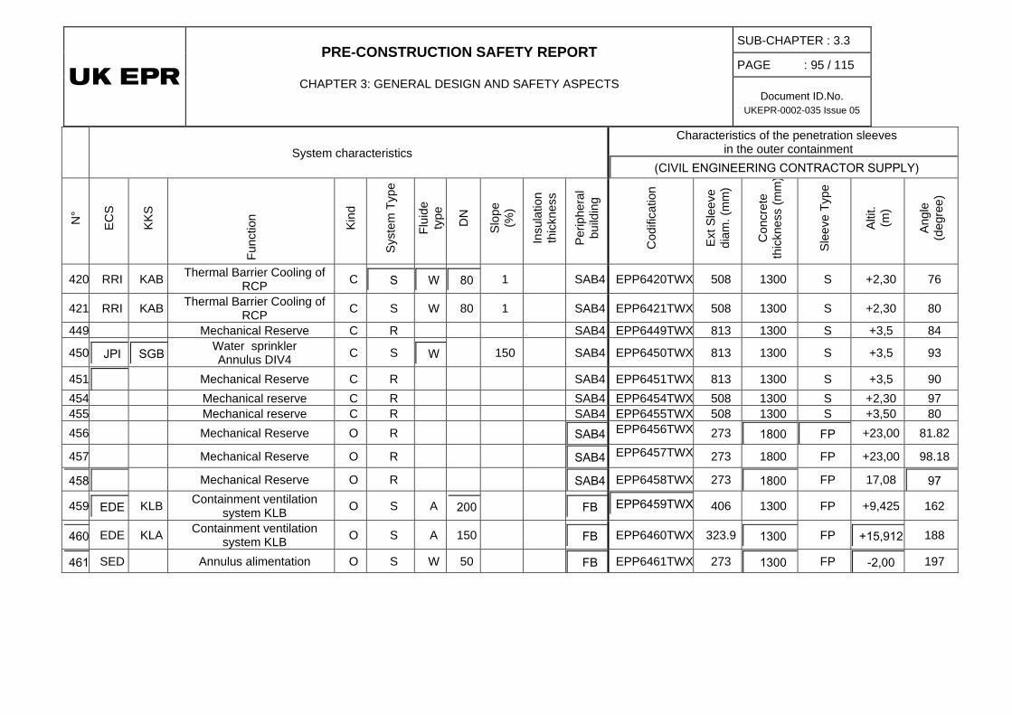
PRE-CONSTRUCTION SAFETY REPORT
CHAPTER 3: GENERAL DESIGN AND SAFETY ASPECTS
SUB-CHAPTER : 3.3
PAGE : 95 / 115
Document ID.No. UKEPR-0002-035 Issue 05
System characteristics Characteristics of the penetration sleeves
in the outer containment (CIVIL ENGINEERING CONTRACTOR SUPPLY)
N°
ECS
KKS
Func
tion
Kind
Syst
em T
ype
Flui
de
type
DN
Slop
e (%
)
Insu
latio
n th
ickn
ess
Perip
hera
l bu
ildin
g
Cod
ifica
tion
Ext S
leev
e di
am. (
mm
)
Con
cret
e th
ickn
ess
(mm
)
Slee
ve T
ype
Altit
. (m
)
Angl
e (d
egre
e)
420 RRI KAB Thermal Barrier Cooling of RCP C S W 80 1 SAB4 EPP6420TWX 508 1300 S +2,30 76
421 RRI KAB Thermal Barrier Cooling of RCP C S W 80 1 SAB4 EPP6421TWX 508 1300 S +2,30 80
449 Mechanical Reserve C R SAB4 EPP6449TWX 813 1300 S +3,5 84
450 JPI SGB Water sprinkler Annulus DIV4 C S W 150 SAB4 EPP6450TWX 813 1300 S +3,5 93
451 Mechanical Reserve C R SAB4 EPP6451TWX 813 1300 S +3,5 90 454 Mechanical reserve C R SAB4 EPP6454TWX 508 1300 S +2,30 97 455 Mechanical reserve C R SAB4 EPP6455TWX 508 1300 S +3,50 80 456 Mechanical Reserve O R SAB4 EPP6456TWX 273 1800 FP +23,00 81.82
457 Mechanical Reserve O R SAB4 EPP6457TWX 273 1800 FP +23,00 98.18
458 Mechanical Reserve O R SAB4 EPP6458TWX 273 1800 FP 17,08 97
459 EDE KLB Containment ventilation system KLB O S A 200 FB EPP6459TWX 406 1300 FP +9,425 162
460 EDE KLA Containment ventilation system KLB O S A 150 FB EPP6460TWX 323.9 1300 FP +15,912 188
461 SED Annulus alimentation O S W 50 FB EPP6461TWX 273 1300 FP -2,00 197

PRE-CONSTRUCTION SAFETY REPORT
CHAPTER 3: GENERAL DESIGN AND SAFETY ASPECTS
SUB-CHAPTER : 3.3
PAGE : 96 / 115
Document ID.No. UKEPR-0002-035 Issue 05
SUB-CHAPTER 3.3 - FIGURE 1 Characteristic Curves of Seismic Spectra

PRE-CONSTRUCTION SAFETY REPORT
CHAPTER 3: GENERAL DESIGN AND SAFETY ASPECTS
SUB-CHAPTER : 3.3
PAGE : 97 / 115
Document ID.No. UKEPR-0002-035 Issue 05
SUB-CHAPTER 3.3 - FIGURE 2
2A - Military Aircraft Loading Diagram
0
10
20
30
40
50
60
70
80
90
100
110
120
0 10 20 30 40 50 60 70 80 90 100 110 120
C2
C1
Force (MN)
Time (ms)
2B – General Aircraft Loading Diagram
0 10 20 30 40 50 60 70 80 90 100
FORC
E (10
4 N)
0
100
200
300
400
500
600
700
800
900
1000
1100
1200
TEMPS (ms)
LEAR JET 23
CESSNA 210
0 10 20 30 40 50 60 70 80 90 1000 10 20 30 40 50 60 70 80 90 100
FORC
E (10
4 N)
0
100
200
300
400
500
600
700
800
900
1000
1100
1200
0
100
200
300
400
500
600
700
800
900
1000
1100
1200
TEMPS (ms)
LEAR JET 23
CESSNA 210
TIME (ms)

PRE-CONSTRUCTION SAFETY REPORT
CHAPTER 3: GENERAL DESIGN AND SAFETY ASPECTS
SUB-CHAPTER : 3.3
PAGE : 98 / 115
Document ID.No. UKEPR-0002-035 Issue 05
SUB-CHAPTER 3.3 - FIGURE 3 Wave Overpressure Loading Diagram
Overpressure (kPa)
0 100 200 300 400 500 Time (ms)
20
10
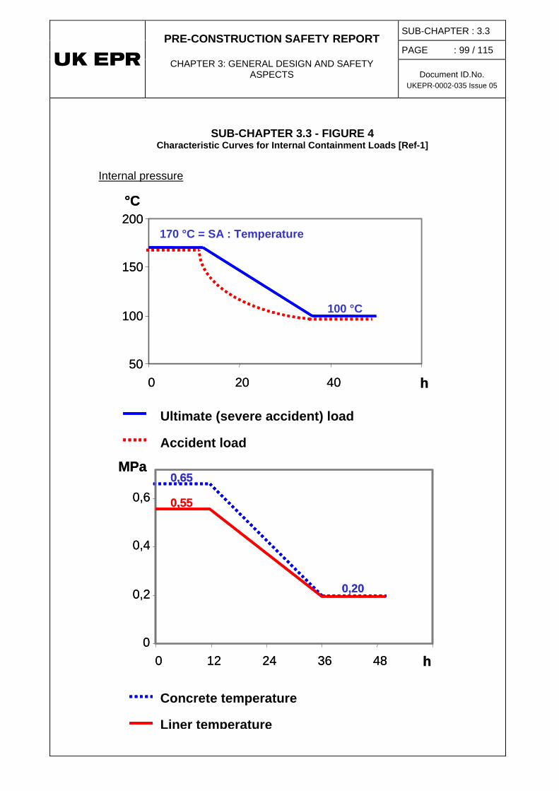
PRE-CONSTRUCTION SAFETY REPORT
CHAPTER 3: GENERAL DESIGN AND SAFETY ASPECTS
SUB-CHAPTER : 3.3
PAGE : 99 / 115
Document ID.No. UKEPR-0002-035 Issue 05
SUB-CHAPTER 3.3 - FIGURE 4 Characteristic Curves for Internal Containment Loads [Ref-1]
50
100
150
200
0 20 40 h
170 °C = SA : Temperature
100 °C
Concrete SA Temperature
Steel liner SA Temperature
°C
50
100
150
200
0 20 40 h
170 °C = SA : Temperature
100 °C
Concrete SA Temperature
Steel liner SA Temperature
Concrete SA Temperature
Steel liner SA Temperature
°C
Internal pressure
SA : Beyond design pressure
SA : Design pressure
0
0,2
0,4
0,6
0 12 24 36 48 h
0,65
0,20
MPa
0,55
SA : Beyond design pressure
SA : Design pressure
SA : Beyond design pressure
SA : Design pressure
0
0,2
0,4
0,6
0 12 24 36 48 h
0,65
0,20
MPa
0,55
Ultimate (severe accident) load
Accident load
Concrete temperature
Liner temperature

PRE-CONSTRUCTION SAFETY REPORT
CHAPTER 3: GENERAL DESIGN AND SAFETY ASPECTS
SUB-CHAPTER : 3.3
PAGE : 100 / 115
Document ID.No. UKEPR-0002-035 Issue 05
SUB-CHAPTER 3.3 - FIGURE 5 Equipment Hatch (lifting mechanism)
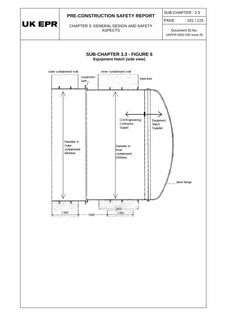
PRE-CONSTRUCTION SAFETY REPORT
CHAPTER 3: GENERAL DESIGN AND SAFETY ASPECTS
SUB-CHAPTER : 3.3
PAGE : 101 / 115
Document ID.No. UKEPR-0002-035 Issue 05
SUB-CHAPTER 3.3 - FIGURE 6 Equipment Hatch (side view)

PRE-CONSTRUCTION SAFETY REPORT
CHAPTER 3: GENERAL DESIGN AND SAFETY ASPECTS
SUB-CHAPTER : 3.3
PAGE : 102 / 115
Document ID.No. UKEPR-0002-035 Issue 05
SUB-CHAPTER 3.3 - FIGURE 7 Personnel Airlock

PRE-CONSTRUCTION SAFETY REPORT
CHAPTER 3: GENERAL DESIGN AND SAFETY ASPECTS
SUB-CHAPTER : 3.3
PAGE : 103 / 115
Document ID.No. UKEPR-0002-035 Issue 05
SUB-CHAPTER 3.3 - FIGURE 8 Standard Piping Penetration
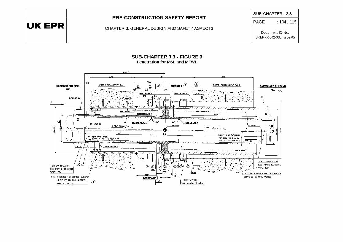
PRE-CONSTRUCTION SAFETY REPORT
CHAPTER 3: GENERAL DESIGN AND SAFETY ASPECTS
SUB-CHAPTER : 3.3
PAGE : 104 / 115
Document ID.No. UKEPR-0002-035 Issue 05
SUB-CHAPTER 3.3 - FIGURE 9 Penetration for MSL and MFWL

PRE-CONSTRUCTION SAFETY REPORT
CHAPTER 3: GENERAL DESIGN AND SAFETY ASPECTS
SUB-CHAPTER : 3.3
PAGE : 105 / 115
Document ID.No. UKEPR-0002-035 Issue 05
SUB-CHAPTER 3.3 - FIGURE 10
High Energy Piping Penetration

PRE-CONSTRUCTION SAFETY REPORT
CHAPTER 3: GENERAL DESIGN AND SAFETY ASPECTS
SUB-CHAPTER : 3.3
PAGE : 106 / 115
Document ID.No. UKEPR-0002-035 Issue 05
SUB-CHAPTER 3.3 - FIGURE 11 Electrical Penetration
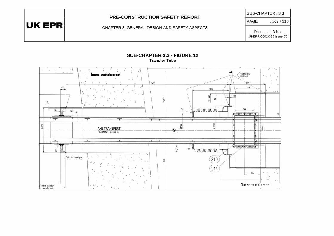
PRE-CONSTRUCTION SAFETY REPORT
CHAPTER 3: GENERAL DESIGN AND SAFETY ASPECTS
SUB-CHAPTER : 3.3
PAGE : 107 / 115
Document ID.No. UKEPR-0002-035 Issue 05
SUB-CHAPTER 3.3 - FIGURE 12 Transfer Tube
PRE-CONSTRUCTION SAFETY REPORT
CHAPTER 3: GENERAL DESIGN AND SAFETY ASPECTS
SUB-CHAPTER : 3.3 PAGE : 108 / 115
Document ID.No. UKEPR-0002-035 Issue 05
SUB-CHAPTER 3.3 – REFERENCES
External references are identified within this sub-chapter by the text [Ref-1], [Ref-2], etc at the appropriate point within the sub-chapter. These references are listed here under the heading of the section or sub-section in which they are quoted.
1. SAFETY REQUIREMENTS AND DESIGN BASIS FOR SAFETY CLASSIFIED STRUCTURES
1.1. INTRODUCTION
[Ref-1] EPR Nuclear Island Civil Engineering Design Process. ECEIG111110 Revision C. EDF. October 2012. (E)
[Ref-2] Civil works dedicated rules for buildings classified C2 “main structures”. ENGSGC110254 Revision B. EDF. June 2012. (E)
[Ref-3] UK EPR – Safety Class 2 Structures – Definition of C2 Safety Requirements. ENSN110130 Revision A. EDF. January 2012. (E)
1.2. CIVIL STRUCTURES CONCERNED
[Ref-1] EPR Nuclear Island Civil Engineering Design Process. ECEIG111110 Revision C. EDF. October 2012. (E)
[Ref-2] EPR - General Hypotheses Note for Civil Engineering Design of Nuclear Island Buildings. ECEIG021405 Revision H1 (TR 07/312). EDF. October 2008. (E)
ECEIG021405 Revision H1 is the English translation of ECEIG021405 Revision H
1.2.5. Structures Common to Buildings within the Nuclear Island
[Ref-1] Common Foundation Raft and Seismic Analysis - GDA Scope. ENGSGC100140 Revision C. EDF. December 2011. (E)
[Ref-2] Reference for design report and drawing package for aircraft shell; this reference contains Security Sensitive material
1.2.10. Other structures
[Ref-1] Civil works dedicated rules for buildings classified C2 “main structures”. ENGSGC110254 Revision B. EDF. June 2012. (E)
[Ref-2] UK EPR – Safety Class 2 Structures – Definition of C2 Safety Requirements. ENSN110130 Revision A. EDF. January 2012. (E)
PRE-CONSTRUCTION SAFETY REPORT
CHAPTER 3: GENERAL DESIGN AND SAFETY ASPECTS
SUB-CHAPTER : 3.3 PAGE : 109 / 115
Document ID.No. UKEPR-0002-035 Issue 05
1.3. DESIGN LOAD CASES AND ASSUMPTIONS
[Ref-1] EPR Nuclear Island Civil Engineering Design Process. ECEIG111110 Revision C. EDF. October 2012. (E)
[Ref-2] EPR Nuclear Island detailed design report (“route map”). ECEIG102182 Revision A. EDF. December 2010. (E)
[Ref-3] EPR Inner Containment Wall detailed design report (“route map”). ECEIG102044 Revision B. EDF. February 2011. (E)
1.3.3. Internal Hazards
[Ref-1] EPR Technical Report TR 96/25. Protection against internal hazards. KWU NA-T/1996/017 B. Siemens. April 1996. (E)
Alternative reference number: ENSN960623 (TR 96-25). EDF
1.3.4. External Hazards
[Ref-1] Protection against External Hazards. KWU NA-T/1996/033 Revision C (TR96-49). AREVA. December 1996. (E)
1.3.6 Consideration of Load Combinations
[Ref-1] UK EPR – Safety Class 2 Structures – Definition of C2 Safety Requirements. ENSN110130 Revision A. EDF. January 2012. (E)
1.4. DESIGN OF STRUCTURES AND INCORPORATION OF SAFETY REQUIREMENTS
1.4.1. Integration of EPR Safety Requirements in Structural Design
1.4.1.3. Accident situations
[Ref-1] C Clement. Safety approach adopted in the design of the EPR containment with a steel liner. ENSN030450 Revision A. EDF. October 2003. (E)
1.4.4. Behavioural Requirements for the Civil Engineering Structures
[Ref-1] ETC-C (EPR Technical Code for Civil works). ENGSGC050076 Revision B. EDF. April 2006. (E)
[Ref-2] UK EPR – Safety Class 2 Structures – Definition of C2 Safety Requirements. ENSN110130 Revision A. EDF. January 2012. (E)
2. DOUBLE WALLED CONTAINMENT WITH STEEL LINER
2.2. DESCRIPTION
[Ref-1] Design criteria for a double-walled containment with a steel liner. ENGSGC090193 Revision A. EDF. September 2009. (E)
PRE-CONSTRUCTION SAFETY REPORT
CHAPTER 3: GENERAL DESIGN AND SAFETY ASPECTS
SUB-CHAPTER : 3.3 PAGE : 110 / 115
Document ID.No. UKEPR-0002-035 Issue 05
ENGSGC090193 Revision A is the English translation of ENGSGC030167 Revision A
2.2.1. Inner Containment
[Ref-1] EPR Nuclear Island Civil Engineering Design Process. ECEIG111110 Revision C. EDF. October 2012. (E)
[Ref-2] Design Change Management Form - Modification of liner floor design for future EPRs. UKEPR-CMF-018. (E)
[Ref-3] EPR Inner Containment Wall detailed design report (“route map”). ECEIG102044 Revision B. EDF. February 2011. (E)
2.2.1.4. Steel Liner
[Ref-1] Design Change Management Form - Modification of liner floor design for future EPRs. UKEPR-CMF-018. (E)
2.3. DESIGN BASIS FOR THE INNER CONTAINMENT
2.3.1. Design Rules and Requirements
[Ref-1] EPR Nuclear Island Civil Engineering Design Process. ECEIG111110 Revision C. EDF. October 2012. (E)
[Ref-2] EPR Inner Containment Wall detailed design report (“route map”). ECEIG102044 Revision B. EDF. February 2011. (E)
2.3.4. FA3 Design Reference Analysis for the Inner Containment Structure
[Ref-1] EPR Inner Containment Wall detailed design report (“route map”). ECEIG102044 Revision B. EDF. February 2011. (E)
2.3.7. Prestressing System Design
[Ref-1] Safety Justification of the Prestressing System of the UK EPR Inner Containment. ENGSGC100010 Revision C. EDF. January 2011 (E)
[Ref-2] Principles of an optimum instrumentation system (DAO) for the UK EPR inner containment. ENGSGC100267 Revision B. EDF. January 2011. (E)
2.4. RELIABILITY OF INNER CONTAINMENT
[Ref-1] Target Reliabilities for UK EPR Structures built with ETC-C. PEPSPF/11.051. AREVA. January 2011. (E)
[Ref-2] Reliability of the EPR Inner containment to Earthquake. ENGSDS100093 Revision B. EDF. January 2011. (E)
[Ref-3] Study of the behaviour of the EPR inner containment wall beyond design-basis conditions. ENGSGC100106 Revision B. EDF. February 2011. (E)

PRE-CONSTRUCTION SAFETY REPORT
CHAPTER 3: GENERAL DESIGN AND SAFETY ASPECTS
SUB-CHAPTER : 3.3 PAGE : 111 / 115
Document ID.No. UKEPR-0002-035 Issue 05
3. CONTAINMENT PENETRATIONS
3.3. PERSONNEL AIRLOCKS
3.3.6. General Operating Principles
[Ref-1] EPR - Equipment hatch and airlocks operating principles. ECEF040241 Revision A (TR 04-140). EDF. April 2004. (E)
4. INTERNAL STRUCTURES
4.3. DESIGN BASIS
4.3.2. Loads and Load Combinations
[Ref-1] EPR Nuclear Island Civil Engineering Design Process. ECEIG111110 Revision C. EDF. October 2012. (E)
[Ref-2] EPR - General Hypotheses Note for Civil Engineering Design of Nuclear Island Buildings. ECEIG021405 Revision H1 (TR 07/312). EDF. October 2008. (E)
ECEIG021405 Revision H1 is the English translation of ECEIG021405 Revision H.
[Ref-3] Hypothesis Note on Reactor Building Containment Internals. SFL-EYRC-003022 Revision F1. SOFINEL. October 2008. (E)
[Ref-4] Reactor Building - Containment Internals – Hypothesis and methodology note. 11787 YR1221 NT 28B01 0001 Revision D1. EDF. October 2008. (E)
Revision D1 is the English translation of 11787 YR1221 NT 28B01 0001 Revision D
4.3.3. FA3 Design Reference Analysis
4.3.3.1. Modelling
[Ref-1] EPR Nuclear Island detailed design report (“route map”). ECEIG102182 Revision A. EDF. December 2010. (E)
4.3.3.2. Description and Methodology of the FA3 Design Reference
[Ref-1] EPR Nuclear Island detailed design report (“route map”). ECEIG102182 Revision A. EDF. December 2010. (E)
4.3.3.3. Values for the Main Actions
[Ref-1] EPR Nuclear Island detailed design report (“route map”). ECEIG102182 Revision A. EDF. December 2010. (E)
PRE-CONSTRUCTION SAFETY REPORT
CHAPTER 3: GENERAL DESIGN AND SAFETY ASPECTS
SUB-CHAPTER : 3.3 PAGE : 112 / 115
Document ID.No. UKEPR-0002-035 Issue 05
4.3.3.3.1. Permanent Actions
[Ref-1] EPR Nuclear Island detailed design report (“route map”). ECEIG102182 Revision A. EDF. December 2010. (E)
[Ref-2] EPR - General Hypotheses Note for Civil Engineering Design of Nuclear Island Buildings. ECEIG021405 Revision H1 (TR 07/312). EDF. October 2008. (E)
4.3.3.3.2. Variable Actions
[Ref-1] EPR Nuclear Island detailed design report (“route map”). ECEIG102182 Revision A. EDF. December 2010. (E)
4.3.3.3.3. Accidental Actions
[Ref-1] EPR Nuclear Island detailed design report (“route map”). ECEIG102182 Revision A. EDF. December 2010. (E)
4.3.3.4. Main Results
[Ref-1] EPR Nuclear Island detailed design report (“route map”). ECEIG102182 Revision A. EDF. December 2010. (E)
4.3.4. Generic Design Analysis
[Ref-1] EPR Nuclear Island Civil Engineering Design Process. ECEIG111110 Revision C. EDF. October 2012. (E)
4.3.4.1. Modelling
[Ref-1] EPR Nuclear Island Civil Engineering Design Process. ECEIG111110 Revision C. EDF. October 2012. (E)
5. OTHER STRUCTURES CLASSIFIED AT CATEGORY I
5.2. DESCRIPTION OF CIVIL STRUCTURES
5.2.1. General Remarks
[Ref-1] EPR Nuclear Island Civil Engineering Design Process. ECEIG111110 Revision B. EDF. June 2012. (E)
[Ref-2] EPR Civil Engineering Standard. ECEIG050051 Revision L1. EDF. October 2009. (E)
5.2.3. Electrical and Safeguard Auxiliary Buildings
5.2.3.1. General remarks
[Ref-1] Concept Design of the MCR for ERP-France Specific Arrangements. SFLEZC008016 Revision B. SOFINEL. February 2008. (E)
PRE-CONSTRUCTION SAFETY REPORT
CHAPTER 3: GENERAL DESIGN AND SAFETY ASPECTS
SUB-CHAPTER : 3.3 PAGE : 113 / 115
Document ID.No. UKEPR-0002-035 Issue 05
[Ref-2] MCR Acoustic Study Justification – Answers to 35-CE-1 and 35-CE-3. ECEIG110015. EDF. December 2010. (E)
5.2.3.3. Structures
[Ref-1] EPR Nuclear Island Civil Engineering Design Process. ECEIG111110 Revision C. EDF. October 2012. (E)
5.2.4. Fuel Building
5.2.4.3. Structures
[Ref-1] EPR Nuclear Island Civil Engineering Design Process. ECEIG111110 Revision C. EDF. October 2012. (E)
5.2.5. Nuclear Auxiliary Building
5.2.5.4. Structures
[Ref-1] EPR Nuclear Island Civil Engineering Design Process. ECEIG111110 Revision C. EDF. October 2012. (E)
5.2.6. Diesel Generator Buildings
5.2.6.3. Structures
[Ref-1] EPR Nuclear Island Civil Engineering Design Process. ECEIG111110 Revision C. EDF. October 2012. (E)
5.2.9. Pool Liners
[Ref-1] Pools and Tanks Liner Design Requirements and Methodology. ENGSGC110243 Revision B. EDF. February 2012. (E)
[Ref-2] Design, Construction and Testing of EPR Pool Liners. ECEIG060543 Revision C1. EDF. June 2009. (E)
ECEIG060543 Revision C1 is the English translation of document ECEIG060543 Revision C.
5.2.10. Structural Steelworks
[Ref-1] EPR Nuclear Island Civil Engineering Design Process. ECEIG111110 Revision C. EDF. October 2012. (E)
[Ref-2] EPR - General Hypotheses to Design Steel Structures. ECEIG051339 Revision B1. EDF. March 2009. (E)
ECEIG051339 Revision B1 is the English translation of ECEIG051339 Revision B.
PRE-CONSTRUCTION SAFETY REPORT
CHAPTER 3: GENERAL DESIGN AND SAFETY ASPECTS
SUB-CHAPTER : 3.3 PAGE : 114 / 115
Document ID.No. UKEPR-0002-035 Issue 05
5.3. DESIGN BASIS
5.3.2. Load Cases and Load Combinations
[Ref-1] EPR Nuclear Island Civil Engineering Design Process. ECEIG111110 Revision C. EDF. October 2012. (E)
[Ref-2] EPR - General Hypotheses Note for Civil Engineering Design of Nuclear Island Buildings. ECEIG021405 Revision H1 (TR 07/312). EDF. October 2008. (E)
ECEIG021405 Revision H1 is the English translation of ECEIG021405 Revision H
5.3.3. FA3 Design Reference Analysis
5.3.3.1. General Modelling
[Ref-1] EPR Nuclear Island detailed design report (“route map”). ECEIG102182 Revision A. EDF. December 2010. (E)
5.3.3.2. Analysis of Buildings on the Common Raft
5.3.3.2.1, Specific modelling
[Ref-1] EPR Nuclear Island detailed design report (“route map”). ECEIG102182 Revision A. EDF. December 2010. (E)
5.3.3.4. Main Conclusions
[Ref-1] EPR Nuclear Island detailed design report (“route map”). ECEIG102182 Revision A. EDF. December 2010. (E)
5.3.4. Generic Design Analysis
[Ref-1] EPR Nuclear Island Civil Engineering Design Process. ECEIG111110 Revision C. EDF. October 2012. (E)
6. FOUNDATIONS
6.2. DESCRIPTION
6.2.1. Common Foundation Raft
[Ref-1] Common Foundation Raft and Seismic Analysis - GDA Scope. ENGSGC100140 Revision C. EDF December 2011. (E)
[Ref-2] EPR Nuclear Island Civil Engineering Design Process. ECEIG111110 Revision C. EDF. October 2012. (E)
6.2.2. Nuclear Auxiliary Building
[Ref-1] Hypothesis note for the Nuclear Auxiliary Building. SFL-EZC-00-8003 Revision C. SOFINEL. March 2007. (E)
PRE-CONSTRUCTION SAFETY REPORT
CHAPTER 3: GENERAL DESIGN AND SAFETY ASPECTS
SUB-CHAPTER : 3.3 PAGE : 115 / 115
Document ID.No. UKEPR-0002-035 Issue 05
6.2.3. Diesel Generator Buildings
[Ref-1] Hypothesis note on civil engineering design of the EPR FA3 Diesel Buildings. SFL-EYRC-0030020 Revision E1 (TR 08/549). SOFINEL. October 2008. (E)
SFL-EYRC-0030020 Revision E1 is the English translation of SFL-EYRC-0030020 Revision E
6.3. DESIGN BASIS
6.3.1. Design Rules and Structural Analysis
6.3.1.1. Common foundation raft
[Ref-1] EPR Nuclear Island Civil Engineering Design Process. ECEIG111110 Revision C. EDF. October 2012. (E)
[Ref-2] UK EPR - Seismic analysis of Foundation Raft. ENGSDS100268 Revision B. EDF. April 2012. (E)
[Ref-3] UK EPR - Methodology for Seismic Analysis of NI buildings. ENGSDS100269 Revision B. EDF. April 2012. (E)
6.3.1.2. Independent foundation rafts
[Ref-1] EPR Nuclear Island Civil Engineering Design Process Note. ECEIG111110 Revision C. EDF. October 2012. (E)
[Ref-2] UK EPR - Seismic analysis of foundation raft. ENGSDS100268 Revision B. EDF. April 2012. (E)
[Ref-3] UK EPR - Methodology for Seismic Analysis of NI buildings. ENGSDS100269 Revision B. EDF. April 2012. (E)
SUB-CHAPTER 3.3 - FIGURE 4
[Ref-1] Design criteria for a double-walled containment with a steel liner. ENGSGC090193 Revision A. EDF. September 2009. (E)
ENGSGC090193 Revision A is the English translation of ENGSGC030167 Revision A