title: pcsr – sub-chapter 13.1 – external hazards protection 13 - hazar… · 29-04-2008 . 03 ....
TRANSCRIPT

UNCLASSIFIED Title: PCSR – Sub-chapter 13.1 – External Hazards Protection
UKEPR-0002-131 Issue 06
Total number of pages: 73 Page No.: I / V
Chapter Pilot: F. FIORAVANTI
Name/Initials
Date 13.11.2012
Approved for EDF by: A MARECHAL Approved for AREVA by: G. CRAIG
Name/Initials Date 16-11-2012 Name/Initials
Date 16-11-2012
UNCLASSIFIED
REVISION HISTORY
Issue Description Date
00 First issue. 02-01-2008
01 Integration of EDF and AREVA comments; issued for INSA review. 31-01-2008
02 Integration of INSA review comments 29-04-2008
03 PCSR June 2009 update:
- Inclusion of references;
- Section 1.2 : Explanation of hazards design principles improved;
- Sections 5 and 6 : Paragraphs added to confirm that quantification of external hazards loads is site dependent and therefore outside scope of GDA: description of hazards loads provided is for FA3 and is given for illustrative purposes only;
- Section 7.2.1.4 : New section added on Electromagnetic Interference Protection;
- Minor changes and references added
27-06-2009
04 Consolidated Step 4 PCSR update:
- Minor editorial changes - Update of references to English translations - Changes following Step 4 assessment:
- clarification of text for seismic design motions (§2.1.5.1, §2.1.6, §2.1.7)
- section 3 “Protection against aircraft crash”; subdivided into §3.1 “Protection against accidental aircraft crash” and §3.2 “Protection against malicious aircraft crash” and text updated
31-03-2011
Continued on next page

UNCLASSIFIED Title: PCSR – Sub-chapter 13.1 – External Hazards Protection
UKEPR-0002-131 Issue 06
Page No.:
II / V
UNCLASSIFIED
REVISION HISTORY (Cont’d)
Issue Description Date
05 Consolidated PCSR update: - References listed under each numbered section or sub-section heading
numbered [Ref-1], [Ref-2], [Ref-3], etc - Minor editorial changes - Addition of methodology and principles for the Hazard Fault Schedule
(§1.2 and new Appendix 1), with reference to an example of a representative Hazard Fault Schedule
- Clarification of text (§2.3, §3.2 and Section 13.1.1 - Table 1) - Modification of terminology (§2.1.1, §7.1.2, §7.2.4.1.1.1, §7.3.1) - Reference for pressure wave updated from “United States Army
Technical Manual TM 5-1300” to “Unified Facilities Criteria UFC 3-340-02” (§4.1.2)
27-09-2012
06 Consolidated PCSR update: - Minor editorial changes - Update of cross-references to Sub-chapters 3.2, 3.3, 5.4, 15.1 (§2.1.1,
§2.1.6, §2.1.7, §2.1.8.2.2)
16-11-2012

UNCLASSIFIED Title: PCSR – Sub-chapter 13.1 – External Hazards Protection
UKEPR-0002-131 Issue 06
Page No.:
III / V
UNCLASSIFIED
Copyright © 2012
AREVA NP & EDF All Rights Reserved
This document has been prepared by or on behalf of AREVA NP and EDF SA in connection with their request for generic design assessment of the EPRTM design by the UK nuclear regulatory authorities. This document is the property of AREVA NP and EDF SA. Although due care has been taken in compiling the content of this document, neither AREVA NP, EDF SA nor any of their respective affiliates accept any reliability in respect to any errors, omissions or inaccuracies contained or referred to in it. All intellectual property rights in the content of this document are owned by AREVA NP, EDF SA, their respective affiliates and their respective licensors. You are permitted to download and print content from this document solely for your own internal purposes and/or personal use. The document content must not be copied or reproduced, used or otherwise dealt with for any other reason. You are not entitled to modify or redistribute the content of this document without the express written permission of AREVA NP and EDF SA. This document and any copies that have been made of it must be returned to AREVA NP or EDF SA on their request. Trade marks, logos and brand names used in this document are owned by AREVA NP, EDF SA, their respective affiliates or other licensors. No rights are granted to use any of them without the prior written permission of the owner.
Trade Mark EPRTM is an AREVA Trade Mark.
For information address:
AREVA NP SAS
Tour AREVA 92084 Paris La Défense Cedex
France
EDF Division Ingénierie Nucléaire
Centre National d'Equipement Nucléaire 165-173, avenue Pierre Brossolette
BP900 92542 Montrouge
France

UNCLASSIFIED Title: PCSR – Sub-chapter 13.1 – External Hazards Protection
UKEPR-0002-131 Issue 06
Page No.:
IV / V
UNCLASSIFIED
TABLE OF CONTENTS
1. GENERAL PRINCIPLES
1.1. LIST OF EXTERNAL HAZARDS AND CONTENT OF THIS SUB-CHAPTER
1.2. GENERAL PRINCIPLES FOR PROTECTION AGAINST EXTERNAL HAZARDS
1.3. CONSIDERATION OF COMBINED EVENTS
2. PROTECTION AGAINST EARTHQUAKES
2.1. SAFETY REQUIREMENTS AND DESIGN BASIS
2.2. DESIGN VERIFICATION
2.3. METHODOLOGY
3. PROTECTION AGAINST AIRCRAFT CRASH
3.1. PROTECTION AGAINST ACCIDENTAL AIRCRAFT CRASH
3.2. PROTECTION AGAINST MALICIOUS AIRCRAFT CRASH
4. PROTECTION AGAINST THE HAZARDS ASSOCIATED WITH THE INDUSTRIAL ENVIRONMENT AND TRANSPORT ROUTES - EXTERNAL EXPLOSION
4.1. SAFETY REQUIREMENTS AND DESIGN BASIS
4.2. DESIGN VERIFICATION
5. PROTECTION AGAINST EXTERNAL FLOODING
5.1. SAFETY REQUIREMENTS
5.2. DESIGN BASIS
5.3. DESIGN VERIFICATION
6. PROTECTION AGAINST EXTREME CLIMATIC CONDITIONS
6.1. SAFETY REQUIREMENTS
6.2. DESIGN BASIS

UNCLASSIFIED Title: PCSR – Sub-chapter 13.1 – External Hazards Protection
UKEPR-0002-131 Issue 06
Page No.:
V / V
UNCLASSIFIED
6.3. DESIGN VERIFICATION
7. PROTECTION AGAINST LIGHTNING AND ELECTROMAGNETIC INTERFERENCE
7.1. SAFETY REQUIREMENTS
7.2. DESIGN BASIS
7.3. DESIGN VERIFICATION
APPENDIX 1: HAZARD FAULT SCHEDULE PRINCIPLES
A1.1. GENERAL OBJECTIVE & CLAIM
A1.2. BASIS OF THE HAZARDS SCHEDULE
A1.3. DESCRIPTION OF THE SCHEDULE & ARGUMENTS
A1.4. INPUT TO CLASSIFICATION & HAZARDS DESCRIPTION
A1.5. SAFETY FUNCTIONS
A1.6. SAFETY FUNCTIONAL GROUPS
A1.7. FAULT ANALYSES
A1.8. CONCLUSIONS

UNCLASSIFIED PRE-CONSTRUCTION SAFETY REPORT
CHAPTER 13: HAZARDS PROTECTION
SUB-CHAPTER : 13.1
PAGE : 1 / 68
Document ID.No. UKEPR-0002-131 Issue 06
UNCLASSIFIED
SUB-CHAPTER 13.1 – EXTERNAL HAZARDS PROTECTION
1. GENERAL PRINCIPLES
The global approach for accounting for hazards is presented in Sub-chapter 3.1.
1.1. LIST OF EXTERNAL HAZARDS AND CONTENT OF THIS SUB-CHAPTER
The list of external hazards taken into account in the EPR design is given here below. The associated justification is provided in Sub-chapter 3.1. For each of these hazards, Sub-chapter 13.1 presents the requirements, the design basis and the design verification method (the PSA aspects are presented in Sub-chapter 15.2).
• Earthquake (section 2),
• Aircraft crash (section 3),
• Hazards associated with the industrial environment and transport routes (external explosion, off-site fire, movement of toxic or corrosive gases) (section 4),
• External flooding (section 5),
• Extreme weather conditions (snow and wind, wind generated missiles, low ambient temperatures, icing and frazil ice, high ambient temperatures, drought) (section 6),
• Lightning and electromagnetic interference (section 7).
When the detailed site safety case is presented, the completeness of this list for the chosen site will be confirmed, and further assessments will be provided.
For the external flooding hazard the design is fully site-dependent. In this case, and in the framework of the Generic Design Assessment, the presentation is reduced to general principles.
1.2. GENERAL PRINCIPLES FOR PROTECTION AGAINST EXTERNAL HAZARDS
For the EPR design process, external hazards are taken into consideration at the design stage consistently with internal events or internal hazards, in two respects as follows:
• on a deterministic level, design basis hazards are subject to the same radiological release criteria as other events which do not lead to core meltdown
• on a probabilistic level, hazards are also analysed for their contribution to the overall risk of core meltdown (see Sub-chapter 15.2).

UNCLASSIFIED PRE-CONSTRUCTION SAFETY REPORT
CHAPTER 13: HAZARDS PROTECTION
SUB-CHAPTER : 13.1
PAGE : 2 / 68
Document ID.No. UKEPR-0002-131 Issue 06
UNCLASSIFIED
The basic design principle is to protect the EPR against external hazards using a "load case" procedure, similar to that undertaken for the design of major components of the reactor systems. This procedure consists of attempting to separate as far as possible:
• the hazard study from the reactor PCC and RRC studies,
• the hazard study and the study of other internal or external hazards.
The consequences of hazards are controlled and limited:
• the objective of the design provisions against external hazards is to ensure that the safety functions performed by the safety classified structures, systems and components which are required to bring the plant in the safe shutdown state, are not inadmissibly affected by the hazard
• design provisions are made as necessary to limit the consequential failures of structures, systems and components which could be source of internal events or internal hazards.
However, it is not always possible to prevent hazards from inducing events not addressed in PCC/RRC or hazard analysis. When this is the case, specific studies must be performed to confirm that the safety objectives have been achieved.
In practice, the design process for external hazards involves the following tasks:
1. The prerequisite for the external hazards design process is the list of reference operating conditions (PCCs – Plant Category Conditions) and the assessment of their radiological consequences, as presented in Chapter 14.
2. For each external hazard, the safety requirements and the design basis define the loads which must be considered and the structures, systems and components which must resist the hazard. The structures, systems and components are designed to withstand both the different load cases associated with the hazard and appropriate combinations with other load cases.
There are typically two types of hazards:
• Hazards such as earthquakes for which all items of equipment that are safety classified, as a consequence of their safety or containment function, are protected (with the possible exception of equipment whose failure would not jeopardise compliance with the radiological release criteria).
• Hazards such as aircraft crash, which have localised effects, and for which protection may be achieved by geographical separation of the required systems or components. In this instance, the partial protection is justified on a probabilistic basis and/or by analysis of the consequences of the failure of the unprotected equipment.
3. Design verification: in addition to the use of PSA, a complementary approach which is usually event-based and includes a functional analysis, is used to assess the dependencies between external hazards and internal events/hazards, and related design measures. (See section 1.3 below for the consideration of combined events).

UNCLASSIFIED PRE-CONSTRUCTION SAFETY REPORT
CHAPTER 13: HAZARDS PROTECTION
SUB-CHAPTER : 13.1
PAGE : 3 / 68
Document ID.No. UKEPR-0002-131 Issue 06
UNCLASSIFIED
4. Justification of exceptions: for hazards where the protection of safety classified equipment is not total, it is demonstrated that the radiological consequences of the hazard event remain compatible with the radiological consequences objectives.
Concerning the load quantification method which is part of the design process, reference is made to principles applied according to safety requirements derived from the Basic Safety Rules (RFS, see Sub-chapter 1.4 for a brief description). As most of the design load values were originally evaluated for French sites, the details of these evaluations are not in general provided in the present sub-chapter. Nevertheless these design load values are expected to be acceptable for generic assessment of a UK EPR.
Finally, given the uncertainties in the assessment of potential climatic changes over reactor life, the initial design of the EPR makes provision for adaptation during operation, to allow for climatic changes larger than those initially envisaged.
In general terms, potential climatic change is addressed in three ways:
• Inclusion at the design stage of additional margins in the cases assessed,
• Assessment of the feasibility of making modifications to the plant,
• Assessment of possible changes to plant operation.
An analysis of the adaptability of the plant exceptions for all relevant climate related hazards will be performed during the Nuclear Site Licence Phase.
External hazard protection is provided to ensure that the safety related functions required to meet the safety objectives discussed in Sub-chapter 3.1 are not unacceptably affected as the result of a hazard. The elementary requirements if the protection of main systems against external hazards listed above is needed are summarised in Section 13.1.1 - Table 1. These protection requirements are based on the hazard principles discussed in Sub-chapter 3.1 and the sections specific to each hazard in this sub-chapter.
The application of these requirements in the design of the systems is discussed in the relevant chapters of System Design manuals describing the design of these systems.
Postulated hazard initiating events and their potential consequences will form the basis of a Hazard Fault Schedule for all identified internal and external hazards, to present the Safety Functions considered necessary to maintain nuclear safety during and after their occurrence, deriving the category of function and therefore the class of Structures, Systems and Components (SSCs) required to deliver such a function. The methodology for a representative Hazard Fault Schedule is given in Appendix 1. Sub-chapter 3.2 details the categorisation of Safety Functions and the classification of SSCs.
1.3. CONSIDERATION OF COMBINED EVENTS
An inventory of the combinations of external hazards with internal faults and/or other (internal or external) hazards, which are taken into account in the EPR design, has been developed [Ref-1]. This inventory contains a comprehensive list of all combined internal faults and/or hazards considered in the design of each external hazard.

UNCLASSIFIED PRE-CONSTRUCTION SAFETY REPORT
CHAPTER 13: HAZARDS PROTECTION
SUB-CHAPTER : 13.1
PAGE : 4 / 68
Document ID.No. UKEPR-0002-131 Issue 06
UNCLASSIFIED
The combined events considered include the following scenarios:
a) Combination of physical phenomena inherent in the hazard
Some external hazards which are associated with meteorological or climate conditions, intrinsically involve a combination of several phenomena. This is the case for natural external flooding. For example a major flood can be due to a prolonged period of heavy rainfall. This event cannot therefore be dissociated from an increased level in the water table or from the arrival of a significant amount of water on the platform. These hazards cannot be considered in isolation of each other.
From this perspective, those hazards which do not involve a combination of several phenomena are more readily susceptible to basic characterisation (for example earthquake, aircraft crash, external explosion).
b) Combinations of the hazard considered with potentially dependent internal or external events or hazards
This scenario refers to the potential for an external hazard to result in either a consequential internal hazard or a consequential internal event such as a PCC event.
To reduce the likelihood of a consequential hazard or internal event decoupling principles are applied. These can include:
• reducing the potential dependency between the external hazard and the reference operating conditions (PCC-2 to PCC-4) or other internal hazards, using specific protection and prevention measures,
• identifying the risk that an external hazard may lead to loss of external power supplies, loss of heat sink, or an other external hazard.
• taking into consideration any potential residual interactions in the design.
c) Combinations of the hazard and independent internal or external initial conditions.
Finally, even when there is no dependency or direct link, the analysis of an external hazard may require consideration of independent physical parameters associated with other external hazards.
For example, there is no link between an earthquake and an extreme ambient temperature. However, the choice of certain parameters (e.g. material properties) requires an assumption to be made on temperature.
In general, there is no need to combine extreme values from separate cases. However, the most common combinations of this type are taken into consideration in order to limit the extent of the studies, which induces further margins.
As a general rule, combined events are considered when there is a dependency which cannot be excluded by a design measure. Additional combined events may also be introduced when there may only be a potential dependency.
Depending on the case, the consideration of combined events has an influence on:
• the definition of the basic loading cases (as can be the case for the external flooding),

UNCLASSIFIED PRE-CONSTRUCTION SAFETY REPORT
CHAPTER 13: HAZARDS PROTECTION
SUB-CHAPTER : 13.1
PAGE : 5 / 68
Document ID.No. UKEPR-0002-131 Issue 06
UNCLASSIFIED
• the list of equipment to be protected against the hazard and the load combinations to be used (this applies to the earthquake for example),
• system operational design assumptions (for example, this is the case for the extreme temperatures).

UNCLASSIFIED PRE-CONSTRUCTION SAFETY REPORT
CHAPTER 13: HAZARDS PROTECTION
SUB-CHAPTER : 13.1
PAGE : 6 / 68
Document ID.No. UKEPR-0002-131 Issue 06
UNCLASSIFIED
SECTION 13.1.1 - TABLE 1
Summary of the Requirements for Protection against External Hazards
This table presents a summary of the requirements for protection against external hazards for the main systems, based on the principles explained in this sub-chapter: the table is used to ensure that the functions which are needed to achieve the safety objectives are not unacceptably affected by the occurrence of an external hazard or subsequent consequential hazards.
High ambient temperatures do not appear in this table as the requirements are embodied in the design assumptions for the different systems.
The detailed consideration of these requirements in the design of the basic systems is described in the relevant chapters.
Earthquake Aircraft crash
External explosion
External flooding
Snow and wind
Extreme cold
Lightning and
EMI(*) F1 electrical
power supply
Yes Yes Yes Yes Yes Yes Yes
APG [SGBS] (F1
functions)
Yes Yes Yes Yes Yes Yes Yes
ARE [MFW(S)] (F1
functions)
Yes Yes Yes Yes Yes Yes Yes
ASG [EFW(S)]
Yes Yes Yes Yes Yes Yes Yes
CFI [CWFS] (F1
functions)
Yes Yes Yes Yes Yes Yes Yes
CRF (F1 function)
Yes Yes Yes Yes Yes Yes Yes
DCL [CRACS]
Yes Yes Yes Yes Yes Yes Yes
DEL [SCWS] Yes Yes Yes Yes Yes Yes Yes DER (1) Yes Yes Yes Yes Yes Yes Yes
DFL No No No No No No No Emergency
diesel generators
Yes Yes Yes Yes Yes Yes Yes
Ultimate diesel
generators
Yes Yes No No Yes Yes No
DMK Yes Yes Yes Yes Yes Yes Yes DVD Yes Yes Yes Yes Yes Yes Yes DVL
[SBVSE] Yes Yes Yes Yes Yes Yes Yes
DVP (F1 functions)
Yes Yes Yes Yes Yes Yes Yes
DWB No No No No No No No

UNCLASSIFIED PRE-CONSTRUCTION SAFETY REPORT
CHAPTER 13: HAZARDS PROTECTION
SUB-CHAPTER : 13.1
PAGE : 7 / 68
Document ID.No. UKEPR-0002-131 Issue 06
UNCLASSIFIED
Earthquake Aircraft crash
External explosion
External flooding
Snow and wind
Extreme cold
Lightning and
EMI(*) DWK [FBVS]
(F1 isolations)
Yes Yes Yes Yes Yes Yes Yes
DWL [CSBVS]
Yes Yes Yes Yes Yes Yes Yes
DWN [NABVS]
No (4) No No No No No No
DWQ [ETBVS]
No No No No No No No
DWW [ABVS]
No No No No No No No
EBA [CSVS] (F1
functions)
Yes Yes Yes Yes Yes Yes Yes
EDE [AVS] Yes Yes Yes Yes Yes Yes Yes ETY [CGCS] No No No Yes Yes Yes No
EVF No No No No No No No EVR [CCVS] Yes No No No No No No EVU [CHRS] Yes(5) No No Yes Yes Yes No Enclosure isolation
Yes Yes Yes Yes Yes Yes Yes
JAC Yes Yes Yes Yes N/A N/A N/A JDT [FDS] Yes Yes Yes Yes Yes Yes Yes JPI [NIFPS] Yes Yes Yes Yes Yes Yes Yes
JPV Yes Yes Yes Yes Yes Yes Yes KER
[LRMDS] No No No No No No No
KRT [PRMS] (F1
functions)
Yes Yes Yes Yes Yes Yes Yes
PTR [FPPS/FPCS]
(2)
Yes Yes(3) Yes(3) Yes Yes Yes Yes
RBS [ABS] Yes Yes Yes Yes Yes Yes Yes RCP [RCS] Yes Yes Yes Yes Yes Yes Yes
RCV [CVCS] (F1
functions)
Yes Yes Yes Yes Yes Yes Yes
REA [RBWMS]
No No No No No No No
REN [NSS] (F1
functions)
Yes Yes Yes Yes Yes Yes Yes
RES (F1 functions)
Yes Yes Yes Yes Yes Yes Yes
RGL [CRDM] Yes Yes Yes Yes Yes Yes Yes RIC (F1
functions) Yes Yes Yes Yes Yes Yes Yes
RIS [SIS] Yes Yes Yes Yes Yes Yes Yes RPE [NVDS]
(1) Yes Yes Yes Yes Yes Yes Yes

UNCLASSIFIED PRE-CONSTRUCTION SAFETY REPORT
CHAPTER 13: HAZARDS PROTECTION
SUB-CHAPTER : 13.1
PAGE : 8 / 68
Document ID.No. UKEPR-0002-131 Issue 06
UNCLASSIFIED
Earthquake Aircraft crash
External explosion
External flooding
Snow and wind
Extreme cold
Lightning and
EMI(*) RPN [NIS] Yes Yes Yes Yes Yes Yes Yes
RRI [CCWS] (F1
functions)
Yes Yes Yes Yes Yes Yes Yes
SAT (1) Yes Yes Yes Yes Yes Yes Yes SEC [ESWS] Yes Yes Yes Yes Yes Yes Yes
SED (1) Yes Yes Yes Yes Yes Yes Yes SEK
[CILWDS] No No No No No No No
SGH Yes Yes Yes Yes Yes Yes Yes SGN (DEA
tanks) Yes Yes Yes Yes Yes Yes Yes
SIR (1) Yes Yes Yes Yes Yes Yes Yes SNL (1) Yes Yes Yes Yes Yes Yes Yes
SRU [UCWS] Yes(5) No No Yes Yes Yes No TEG [GWPS]
(1) Yes Yes Yes Yes Yes Yes Yes
TEP [CSTS] No No No No No No No TER
[ExLWDS] (EPR
collector)
No No No No No No No
TES [SWTS] No No No No No No No TEU [LWPS] No No No No No No No VDA [MSRT] Yes Yes Yes Yes Yes Yes Yes VVP [MSSS] Yes Yes Yes Yes Yes Yes Yes
(*): Electro Magnetic Interferences
NOTES
N/A not applicable (1) Containment Isolation functions only. (2) Cooling trains, containment penetrations and isolation of the draining
pipework. (3) Does not apply to the third cooling train. (4) With the exception of the air intake isolation dampers. (5) The two main lines are SC1

UNCLASSIFIED PRE-CONSTRUCTION SAFETY REPORT
CHAPTER 13: HAZARDS PROTECTION
SUB-CHAPTER : 13.1
PAGE : 9 / 68
Document ID.No. UKEPR-0002-131 Issue 06
UNCLASSIFIED
2. PROTECTION AGAINST EARTHQUAKES
2.1. SAFETY REQUIREMENTS AND DESIGN BASIS
The identified risk arising from an earthquake is direct or indirect damage to equipment needed to bring the plant to, and maintain it in, a safe shutdown state. Indirect damage is associated with the failure of adjacent equipment or consequential internal hazards resulting from the earthquake.
Following an earthquake, the objective of the protection is to ensure that the safety functions needed to return and maintain the plant in a safe shutdown state are not unacceptably affected.
2.1.1. Safety Requirements Concerning Civil Structures, Mechanical Equipment and Electrical Systems
The mechanical equipment, electrical systems and civil structures required to achieve the safety objectives must be subject to seismic classification. The seismic classification principles (SC1 and SC2) are defined in Sub-chapter 3.2 (Classification of Structures, Equipment and Systems).
Structures, materials and systems must be designed so that they are able to fulfil their functions, maintain their integrity or remain stable under the conditions caused by the seismic movements. Seismic events must be considered in the design of the plant. Sufficient margins to fulfil the overall EPR probabilistic objective must be included (refer to Sub-chapter 15.0 - Safety Requirements and PSA Objectives).
Different types of requirements may be associated with the equipment:
• Stability: the stability of a component is its ability to resist the loads, which have a tendency to modify its position or orientation (for example, which have a tendency to cause the component to tilt, fall or slide in an unacceptable manner or which could lead to a breakage of some components). The stability of a component relies upon the stability and resistance of its supports.
• Integrity: this is defined as the ability of a component in a pressurised system to resist the specified loads.
• Functional Capability: the ability of a component in a pressurised system to resist the specified loads with limited deformation such that its operational capacity is not impaired by a possible flow reduction.
• Operability: the ability of a system, or component of a system, including its necessary auxiliaries, supports and electrical power supplies, to perform its functions and meet the safety objectives.
The requirements associated with the civil structures are defined for the different load combinations considered, including those caused by a postulated earthquake in Sub-chapter 3.3 - Design of Safety Classified Civil Structures. They are deduced from the general behavioural requirements arising from the following:
• Stability: behavioural requirements attributed to the main wind bracing system, the purpose of which is to prevent the collapse of a civil structure.

UNCLASSIFIED PRE-CONSTRUCTION SAFETY REPORT
CHAPTER 13: HAZARDS PROTECTION
SUB-CHAPTER : 13.1
PAGE : 10 / 68
Document ID.No. UKEPR-0002-131 Issue 06
UNCLASSIFIED
• Local stability: behavioural requirements, which are expressed in terms of static balance, mechanical resistance and rigidity.
• Integrity of equipment supports: behavioural requirements, which describe the fact that the structural elements, which support the items of equipment meet the requirements attributed to this equipment.
• Containment: the aim of the containment function is to limit the release of hazardous materials into the environment.
• Absence of interaction: the aim is to prevent, during an earthquake, impacts between adjacent components (including structures). This is defined as a limitation in the movements of these components relative to the separation distance between them.
2.1.2. Applicable Regulation - Basic Safety Regulations - Technical Guidelines - Codes - Standards
The Technical Guidelines are identified in Sub-chapter 3.1.
Technical Guidelines A.2.5, F2.1, F2.2.1 are applicable.
Depending on the seismic classification of the buildings and equipment, the main codes used are ETC-C, RCC-M, RCC-E, and the French seismic construction regulations (see Sub-chapter 3.8).
2.1.3. Seismic Design Motions
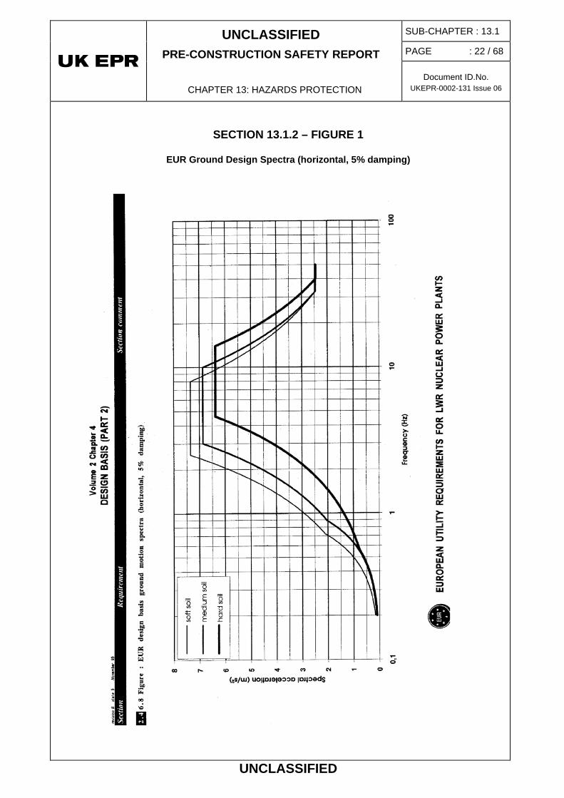
The design and qualification of seismic classified equipment takes into consideration a set of standard conditions: the sets of EUR design spectra (see Section 13.1.2 – Figure 1) scaled at 0.25g in horizontal direction, associated with six standard ground conditions (SA, MA, MB, MC, HA, HF) described below. The vertical acceleration is equal to two-thirds horizontal acceleration.
Soft ground SA
Average ground
MA
Average ground
MB
Average ground
MC
Hard ground
HA
Hard ground
HF
Shear Modulus MN/m2 150 600 1000 2500 6000 10800
17100
Density t/m3 1.9 2.1 2.1 2.1 2.5 2.5
Poisson’s Ratio - 0.48 0.40 0.40 0.40 0.30 0.32
0.35
Material damping % 8 5 5 5 3 3

UNCLASSIFIED PRE-CONSTRUCTION SAFETY REPORT
CHAPTER 13: HAZARDS PROTECTION
SUB-CHAPTER : 13.1
PAGE : 11 / 68
Document ID.No. UKEPR-0002-131 Issue 06
UNCLASSIFIED
• The SA, MA, MB, MC and HA ground conditions correspond to homogeneous ground. The HF ground condition corresponds to the geological conditions of a specific stratified site.
o A first layer of 6 meter thickness under the level of the foundation, with a shear modulus of 10,800 MN/m2 and Poisson ratio of 0.32,
o A second layer of more than 500 m thickness, with a shear modulus of 17,100 MN/m2 and Poisson ratio of 0.35.
2.1.4. Load Combination Rules
In accordance with the Technical Guidelines, some conventional load combinations are used for the design and / or qualification of certain structures or equipment. These load combinations are not intended to suggest a real link between the design earthquake and PCC, but are used to provide margins in the design:
• The combination of stresses resulting from the design ground spectrum and those resulting from a LOCA (guillotine break in the pressuriser surge line) is taken into account in designing the inner containment, the reactor building internal structures and the reactor vessel internals.
• The combination of stresses resulting from the design ground spectrum and those resulting from PCC-2 to PCC-4 events is taken into account in the design of seismic category 1 classified equipment, including PCC-2 to PCC-4 events in which the initiating event does not correspond to the failure of non-seismic classified items. The criteria associated with PCC-4 events are considered. These combinations ensure the ability of equipment to resist an earthquake occurring in the long term after a PCC accident.
• The equipment qualification sequence for seismic classified equipment (defined in Sub-chapter 3.6 – Qualification of Electrical and Mechanical Equipment for Accident Conditions) includes a seismic test phase, combined with irradiation and pressure/temperature accident test phases.
In addition, relevant meteorological parameters are included in the seismic design of the civil structures and materials:
• Wind: the combination of stresses resulting from the design ground spectrum and the stresses resulting from wind (Design Basis Earthquake + 0.2 maximum wind) is taken into account for designing the cladding and chimneys.
• Snow: the combination of stresses resulting from the design ground spectrum and the stresses resulting from snow (Design Basis Earthquake + 0.2 maximum snow) are taken into account in the design of buildings.
o External temperatures (within the limits of the high and low design values).
o The level of the water table.

UNCLASSIFIED PRE-CONSTRUCTION SAFETY REPORT
CHAPTER 13: HAZARDS PROTECTION
SUB-CHAPTER : 13.1
PAGE : 12 / 68
Document ID.No. UKEPR-0002-131 Issue 06
UNCLASSIFIED
2.1.5. Rules and Methods used for the Dynamic Analysis of the SC1 Buildings
Several dynamic analyses are performed for each building:
• The seismic response of each building, of the nuclear island, is calculated using the set of standard conditions (EUR 0.25g ground spectrum associated to six different ground conditions). These analyses supply the in-structure spectra for the design and/or qualification of the safety related structures, systems and components.
• The seismic response of each building is also calculated for the site ground conditions associated with the corresponding EUR spectrum which is set at:
• 0.25 g for the main structures,
• A suitable level given the site seismicity for the site structures.
These analyses supply the seismic stresses for design of the civil structures.
2.1.5.1. SC1 buildings analysed
The list of SC1 classified buildings is established by applying the classification rules defined in Sub-chapter 3.2. Sub-chapter 3.3 also describes the general measures which are taken for designing these structures.
The reactor building is a cylindrical structure comprised of reinforced and pre-stressed concrete. Four rectangular reinforced concrete buildings are attached to the reactor building (safeguard and fuel buildings), forming a cross shape with the reactor building at the centre.
All of these buildings are founded on a common raft of variable thickness. They are designated "buildings on the common foundation raft".
The following five EPR structures are therefore analysed together:
• Safeguard auxiliary buildings 1, 2, 3, 4;
• Fuel building;
• Internal structures;
• Inner containment;
• Outer containment.
Other dynamic analyses are performed for the Main Pump House, the Nuclear Auxiliary Building and the Diesel Generator Buildings.
For SC1 buildings and structures in the standardised part of the installation (nuclear island), earthquakes are taken into account by considering design seismic motions in high standard/ generic spectra (i.e. EUR spectra scaled at 0.25g, see section 2.1.3) so that this part of the plant may be easily duplicated on different sites.
• SC1 buildings and structures that are site-specific are addressed in section 2.1.6 below.

UNCLASSIFIED PRE-CONSTRUCTION SAFETY REPORT
CHAPTER 13: HAZARDS PROTECTION
SUB-CHAPTER : 13.1
PAGE : 13 / 68
Document ID.No. UKEPR-0002-131 Issue 06
UNCLASSIFIED
The UK generic site is assumed to have a seismic activity and soil properties covered by the Design Basis Earthquake (DBE) and associated standard ground conditions. It will be demonstrated that, for typical UK sites, the DBE considered in the UK EPR design basis is consistent with the fault analysis requirements, when data becomes available for relevant sites later in the licensing process.
2.1.5.2. Analysis of ground / structure interaction
For the dynamic calculations, the dynamic behaviour of the free field soil is represented by springs and dashpots.
Complex valued stiffnesses (impedance functions) are evaluated and impedance matrices for the nodal points, which are common to the structure and the soil region are calculated for different soil conditions. These functions are used to define springs and dampers, which are tuned to the global frequencies of the soil-structure system.
For the dynamic analysis, which supplies the in-structure, or floor spectra for the design and/or qualification of equipment, in the main buildings of the installation, the six standard ground conditions are considered. Apart from the HF condition, the ground is modelled by a homogenous half-space.
For the dynamic analysis, which supplies the in–structure, or floor spectra for design of the site structures, the specific site ground conditions are taken into account, as well as the site stratigraphy. A range from 2/3 to 3/2 of the ground shear modulus is considered.
The calculation of the impedance functions uses the following assumptions:
• The foundation raft is considered to be rigid,
• The impedances, which are complex frequency dependent functions, are calculated for the 6 degrees of freedom for a rigid massless foundation slab. The real parts of these functions represent the frequency dependent stiffness, and the imaginary parts the damping in the ground-foundation system,
• The global foundation stiffnesses are uniformly distributed beneath the foundation raft. This distribution is performed so that the foundation global forces and ground level displacements are consistent with the global stiffness for each of the 6 degrees of freedom,
• The ground is considered to be homogeneous; the term corresponding to the radiative damping is weighted by a coefficient of ½,
• Finally, the reduced modal damping value is limited at 30%.
2.1.5.3. Modelling of buildings
2.1.5.3.1. Description of analysed structures
The Nuclear Auxiliary Building, the Access Towers and the Diesel Generator Buildings are represented both by beam element and lumped mass models, and by three-dimensional finite element models.

UNCLASSIFIED PRE-CONSTRUCTION SAFETY REPORT
CHAPTER 13: HAZARDS PROTECTION
SUB-CHAPTER : 13.1
PAGE : 14 / 68
Document ID.No. UKEPR-0002-131 Issue 06
UNCLASSIFIED
The buildings on the common foundation raft are represented by a complete three-dimensional finite element model.
The stiffness of each structural element is represented in a realistic manner by spring, beam or shell elements. The 2D shell elements take into account the bending forces and the membrane stresses.
The model provides a basis for the subsequent dynamic analyses. It has several sub-structures:
• The inner containment: the structure is fabricated from pre-stressed variable thickness concrete, with an internal leak tight metal liner.
• The outer containment: the structure is fabricated from variable thickness reinforced concrete.
• An external shell for protection against aircraft crashes.
• The towers: reinforced concrete structures connected to the outer containment. These towers are also connected to the external walls of the adjacent structures.
• Reactor Building internal structures: reinforced concrete, mainly comprising the primary structure (reactor pits), the secondary structure (cylindrical wall with intermediate walls and platforms) and the reactor pool (reactor cavity and storage compartment). The internal structures are mounted on the reactor building foundation raft via a thick concrete slab.
• The Fuel Building: reinforced concrete structure. The main platforms and the vertical walls are modelled. The fuel building internal structures are decoupled from the external walls of the aircraft protection shell.
• The Safeguard Auxiliary Buildings: reinforced concrete structures. The main platforms and the vertical walls are modelled.
All of these structures are connected to a common foundation raft, which is modelled by variable thickness finite elements.
In order to represent the thickness of the foundation base, the rigidity of the lowest layer of the finite elements, which connect the structures to the foundation base is increased.
All of the structures are of reinforced concrete, except for the inner containment wall of the reactor building, which is a cylindrical pre-stressed concrete shell surmounted by a dome.
2.1.5.3.2. Material properties
For the reinforced and pre-stressed concrete structures, the material properties are in accordance with the EPR Technical Code for civil works, ETC-C.
2.1.5.3.3. In-structure spectra calculations and forces in the civil structures [Ref-1]
The floor response spectra are calculated for two horizontal directions and the vertical direction, for each ground condition, using modal time history superposition. They are calculated separately for different levels of the building and are grouped in specific areas. The spectra for each specific area are then enveloped and smoothed.
UNCLASSIFIED PRE-CONSTRUCTION SAFETY REPORT
CHAPTER 13: HAZARDS PROTECTION
SUB-CHAPTER : 13.1
PAGE : 15 / 68
Document ID.No. UKEPR-0002-131 Issue 06
UNCLASSIFIED
These spectra are presented for a large range of damping values, and are used for design and/or qualification of the equipment in the relevant buildings.
The rigid body accelerations of the floor response spectra corresponding to the site ground conditions are used for further quasi-static structural analyses of these buildings.
2.1.6. Criteria and Methods applied to the Pumping Station (or other site-specific SC1 buildings)
The Pumping Station is described in section 5 of Sub-chapter 3.3 – Other Structures Classified at Category 1. It is the only site-specific SC1 building in the EPR generic design, in which the Ultimate Heat Sink (UHS) is assumed to be once-through. The following criteria and method would also apply to any UHS building and structure if another UHS design was considered.
The Pumping Station is a site structure. In accordance with the general classification principles, (see Sub-chapter 3.2) it is seismic category 1 (SC1)
The ground response spectra used are the EUR spectra corresponding to the site ground conditions, suitably scaled to take account of the site seismicity. A site-specific spectrum corresponding to the Site Design Basis Earthquake (i.e. site-specific design motions) is used in the design. This site specific spectrum must be:
• at least equal to the earthquake defined by the application of the safety rules. (In the UK: the SAPs, which stipulate that the DBE should conservatively have a predicted frequency not exceeding more than once in 10,000 years)
• high enough to achieve the probabilistic criteria as defined in PCSR Chapter 15.
Ground-structure interaction phenomena are taken into account using 3D modelling. All ground layers down to the bedrock, including the backfill, are considered.
2.1.7. Criteria and Methods applied to SC2 buildings and structures.
Some buildings and structures, or some part of buildings and structures, are classified SC2 (see Sub-chapter 3.2).
Criteria and methods defined in section 2.1.5 above are applied to SC2 classified buildings and structures in the standardised part of the installation (nuclear island).
Criteria and methods defined in section 2.1.6 above are applied to SC2 classified buildings and structures that are site-specific. This is the case for the Turbine Hall and for the Operational and Maintenance Building.
2.1.8. Rules and Methods applied to the Dynamic Analysis of the Components and Internal Structures
2.1.8.1. Seismic analysis method
Several methods of seismic analysis may be implemented. The methods, which are most generally used, are the modal methods (spectral or temporal) and, additionally, the equivalent static method.

UNCLASSIFIED PRE-CONSTRUCTION SAFETY REPORT
CHAPTER 13: HAZARDS PROTECTION
SUB-CHAPTER : 13.1
PAGE : 16 / 68
Document ID.No. UKEPR-0002-131 Issue 06
UNCLASSIFIED
2.1.8.1.1. Sub-systems other than the primary loops
The analysis of seismic category 1 systems and components is performed, where possible, using the response spectrum approach, which is based on the natural period, mode shapes and appropriate damping factors for the particular systems.
The floor response spectra, as determined from the building dynamic analysis, are considered. The acceleration values are selected for each mode, based on natural frequency and damping.
Three separate independent analyses are performed for two horizontal directions and the vertical direction. The results obtained for each direction are then combined using a suitable method.
A detailed description of the dynamic analyses is supplied in Sub-chapter 3.4.
The dynamic analysis of the different systems and components is based on finite element models. The capacity of current computers and calculation codes allow highly detailed modelling of the different mechanical components. However, the appropriate level of complexity in the models must be limited by the validation.
2.1.8.1.2. Primary Coolant Loops
The response of the primary loops is determined using either the spectral or the temporal method.
The modal spectral analysis uses the set of in-structure spectra corresponding to the anchoring points for the main primary system. The temporal analysis uses the accelerograms extracted from the anchoring points of the primary system three-dimensional ground-structure interaction analysis.
2.1.8.2. Procedure used to model equipment
2.1.8.2.1. General points
The dynamic analysis of seismic category 1 equipment is based on finite element modelling, adopting the following principles:
• The modelling must be able to include all natural modes, which have a significant contribution to the seismic response. By default, all of the modes within the peak range of the floor response spectrum, which is representative of the seismic load applied to the equipment, must be taken into consideration.
• Where necessary, the contribution of those modes whose frequency exceeds the peak range of the floor response spectrum must be taken into consideration.
2.1.8.2.2. Specific analysis of primary coolant loops
The analysis of the primary loops is described in Sub-chapter 3.4. The analysis is performed using the modal spectral analysis method described below.
The modal spectral analysis method is by far the most common method used for this type of calculation. The spectra used correspond to the floor response spectra at the steam generator upper support.

UNCLASSIFIED PRE-CONSTRUCTION SAFETY REPORT
CHAPTER 13: HAZARDS PROTECTION
SUB-CHAPTER : 13.1
PAGE : 17 / 68
Document ID.No. UKEPR-0002-131 Issue 06
UNCLASSIFIED
The model used comprises four primary loops and the reactor vessel. This enables consideration of the possible dynamic coupling (translation and rotation) of the four loops and the reactor vessel on its supports.
Main assumptions
The influence of the stiffness of the secondary lines (steam lines and feed water lines) is taken into consideration by associating rigid matrix type elements with these lines. However, because of their relative flexibility and low mass, they have little effect on the system natural frequency.
The boundary conditions do not change during an earthquake. This assumption is inherent to the analysis method, which presumes a linear structure and standard conditions at the boundaries. In practice, this restriction requires the clearances to exceed the seismic movements so that there is no contact or significant impact during the earthquake.
Small gaps are considered closed in the linear model used in the modal analysis. Hence, additional static calculations are performed to take account of this simplification. The results obtained are then added to the results of the spectral analysis.
The structure itself (excluding gaps) remains linear under seismic load. The supports are designed to remain elastic under the maximum stresses resulting from a Design Basis Earthquake (DBE) or a break in any auxiliary line connected to the primary system or a break in a main steam line.
The anchor rods are pre-stressed to a value, which takes into account the maximum load of the Design Basis Earthquake and the additional load of a pipework break.
The hydraulic snubbers and support legs, described in section 9 of Sub-chapter 5.4 (Primary Component Supports), also introduce non-linearity. Their stiffness depends strongly on the direction of the acceleration. The tensile and compression loads are not applied to the same mechanical parts, which explain the difference in stiffness. For these supports, the stiffness used in the analysis is equivalent to the average value of the tensile-compression stiffness.
The model comprises the following components: the reactor vessel, the four primary loops, the pressuriser and surge line. Each loop includes a hot leg, a steam generator, a crossover leg, a reactor coolant pump and a cold leg. The primary system is modelled using finite elements. The three-dimensional (3-D) model comprises straight branch legs, bends, lumped masses, springs and rigid elements.
Model
The geometry, the physical properties and the materials, which are associated with these elements, are representative of the mass, inertia and stiffness characteristics of the equipment described.
Certain gaps are assumed closed, i.e. the two opposite surfaces are considered to be in contact with each other. Closure of these gaps is accounted for by additional static analysis, the results of which are added to those of the spectral modal analysis.
With regard to the seismic model, certain degrees of freedom have been considered as being dynamic degrees of freedom (R.J. GUYAN reduction). These dynamic degrees of freedom (approximately 600) are selected by taking into consideration the GUYAN technique (low stiffness and large mass).

UNCLASSIFIED PRE-CONSTRUCTION SAFETY REPORT
CHAPTER 13: HAZARDS PROTECTION
SUB-CHAPTER : 13.1
PAGE : 18 / 68
Document ID.No. UKEPR-0002-131 Issue 06
UNCLASSIFIED
The seismic calculations for the primary loops are performed using the floor response spectra originating from the dynamic analysis of the building.
Calculation parameters
The floor response spectra are calculated at different levels and for different damping values.
2.1.8.3. Seismic analysis of reactor internals
The reactor vessel internal structures are studied by temporal analysis using the non-linear modal superposition method. Suitable seismic excitations are used and applied to the modal representation of the system. For this representation, the vessel internal structures, the reactor vessel and the fuel assemblies are modelled in the form of springs, concentrated masses or beam elements. A finite element structural code (for example, SYSTUS) is used to calculate the response of the non-linear system. The result of this analysis is then combined with the other loads for the mechanical design of each component based on the RCC-M (see Sub-chapter 3.8).
The dynamic analysis for the vessel and its internal structures also calculates, in a temporal form, the displacements necessary for the analysis of the fuel elements and control rods.
The analysis of the vessel internal structures is described in Sub-chapter 3.4.
2.1.8.4. Use of the equivalent static method
This method is a simplification of the spectral method. For each displacement direction, the response of the structure is calculated by applying a uniform static acceleration.
The rules for combining different displacement directions are identical to those used for the spectral method.
2.1.8.4.1. Consideration of the three seismic displacement components
The response is calculated for each of three orthogonal earthquake displacement directions (two horizontal, plus vertical). The results are combined in quadrature.
With regard to the components of the steam supply system, the method used to combine the loads from the three analyses is based on the following:
• The peak responses of the different modes for the same seismic excitation do not occur at the same time.
• The peak responses of a specific mode caused by seismic excitations in different directions do not occur at the same time and are uncorrelated.
• The maximum responses of the different modes and in the three directions are not simultaneous.
In order to implement the above principles, the three seismic translation components are statistically combined using a suitable method.

UNCLASSIFIED PRE-CONSTRUCTION SAFETY REPORT
CHAPTER 13: HAZARDS PROTECTION
SUB-CHAPTER : 13.1
PAGE : 19 / 68
Document ID.No. UKEPR-0002-131 Issue 06
UNCLASSIFIED
2.1.8.5. Combination of modal responses
When the spectral method is used, all of the modal responses and the movements, stresses, times and/or accelerations are combined using a suitable method, which enables, where necessary, consideration of closely spaced frequency modes.
2.1.8.6. Multi-supported equipment and components
The seismic analysis of multi-supported equipment must take into consideration:
• The different spectra of the floors and platforms which correspond to the different levels of equipment anchoring,
• The differential movements between these different anchoring levels.
2.1.9. Inspection Earthquake and Seismic Instrumentation
An inspection earthquake is defined. It represents the level of earthquake below which, if it were to occur, there would be no requirement for specific verification or inspection of the safety significant components before continued normal operation or return to service. This inspection earthquake corresponds to a maximum horizontal free field floor acceleration of 0.05g. This acceleration corresponds on the site to an intensity below VI on the MSK scale.
The procedure which is implemented when an earthquake is experienced and/or measured on site is illustrated in Section 13.1.2 – Figure 2.
In order to collect the data necessary for the analysis of such events, seismic instrumentation is installed. The role of this instrumentation, if a certain acceleration level is exceeded on site, is to generate an alarm in the control room and to trigger recording of the seismic displacements. The automatic triggering of the recording is indicated in the control room.
If the maximum accelerations exceed the Inspection Earthquake level, more detailed analyses, with the plant in operation, is required in order to analyse whether or not the installation has been stressed above the elastic range and if it is still within normal operating conditions.
2.2. DESIGN VERIFICATION
2.2.1. Consistency of the Design Assumptions in Relation to the Site Conditions
The different design assumptions used (design ground spectrum and ground conditions) are to be compared with the design seismic displacements specified for the specific site. The comparison may be performed directly on the spectrum in the free field or, if necessary, on the seismic stresses in the structures and materials. In some instances, a complete new analysis of certain structures or components may be necessary.

UNCLASSIFIED PRE-CONSTRUCTION SAFETY REPORT
CHAPTER 13: HAZARDS PROTECTION
SUB-CHAPTER : 13.1
PAGE : 20 / 68
Document ID.No. UKEPR-0002-131 Issue 06
UNCLASSIFIED
2.2.2. Verification of Plant Design: "Earthquake Event" Procedure [Ref-1]
A specific verification termed an ‘Earthquake Event’ is performed. Application of the procedure leads to the identification of seismic category 2 structures and equipment in accordance with the principles in Sub-chapter 3.2. The purpose is to identify those items which are not included in seismic category 1, but whose failure, due to the local and/or global effects of the earthquake, may have an effect on seismic category 1 components or may jeopardise their qualification and, more generally, may prevent the achievement of the safety objectives as defined in Sub-chapter 3.1. The methodology requires, initially, application of one by one consequential failure, and subsequently, the effect of multiple failures is analysed.
2.2.3. Specific Analysis of PCC-2 to PCC-4
A specific analysis is performed for all PCC-2 to PCC-4, which assume a seismic event combined with a Total Loss of Off-Site Power Supplies following the earthquake.
The rules for these studies are defined in Sub-chapter 14.0 - Assumptions and Requirements for the PCC Accident Analyses.
2.2.4. Verification of Seismic Margins
The choice of level of seismic event and the conservative nature of the seismic design process ensure the existence of safety margins with respect to earthquakes.
A Seismic Margin Assessment is performed (see Sub-chapter 15.6).
2.3. METHODOLOGY
The methodology for the layout analysis of equipment in buildings with regard to a seismic event [Ref-1] requires the identification of equipment not designed according to the DBE and which represents a potential risk to all safety-classified equipment.
Initially, the layout is considered to be undamaged and the reactor is assumed to be in normal operation or subject to a normal operational transient (classification PCC-1). All safety-classified equipment has to be protected from non earthquake classified equipment. Earthquake events are assumed to generate incidents of moderate frequency (classification PCC-2) due to damage to equipment that is not seismically classified. The damage to items of non-classified equipment must in no case cause an accident whose consequences are greater than those of hypothetical accidents (classification PCC-4). The aim of this study is to identify corrective actions such as: modification of layout, reinforcement of restraints on non seismically qualified equipment, isolation of equipment in line with an accepted codes of practice, demonstration that the frequency of seismic consequences is acceptably low by increasing the seismic qualification with respect to the DBE, or provision of physical protection of the target by a structure which is itself designed to withstand the DBE.
The analysis of the multiple failures of non-seismically qualified equipment [Ref-2] is carried out following the seismic analysis of the single failures. The failures to be considered, within the framework of this analysis, are the ones which lead to a flooding, a temperature increase or a humidity increase.
The aim is to define an appropriate approach in order to analyse the multiple failures of non-seismic equipment in the event of seismic event. For that, the document specifies:

UNCLASSIFIED PRE-CONSTRUCTION SAFETY REPORT
CHAPTER 13: HAZARDS PROTECTION
SUB-CHAPTER : 13.1
PAGE : 21 / 68
Document ID.No. UKEPR-0002-131 Issue 06
UNCLASSIFIED
• The type of failures to be analysed,
• The concurrence rules,
• The location of these failures (if needed),
• The acceptance criterion.
The analysis of equipment installation with regard to an earthquake with multiple failures [Ref-3] [Ref-4] consists of identifying the risks of seismic failure on important safety equipment, classified SC1, by equipment without equivalent earthquake classification. Such equipment may initiate, after an earthquake, a flooding event, changes in ambient temperature and increased humidity (including spray).
UNCLASSIFIED PRE-CONSTRUCTION SAFETY REPORT
CHAPTER 13: HAZARDS PROTECTION
SUB-CHAPTER : 13.1
PAGE : 22 / 68
Document ID.No. UKEPR-0002-131 Issue 06
UNCLASSIFIED
SECTION 13.1.2 – FIGURE 1
EUR Ground Design Spectra (horizontal, 5% damping)

UNCLASSIFIED PRE-CONSTRUCTION SAFETY REPORT
CHAPTER 13: HAZARDS PROTECTION
SUB-CHAPTER : 13.1
PAGE : 23 / 68
Document ID.No. UKEPR-0002-131 Issue 06
UNCLASSIFIED
SECTION 13.1.2 – FIGURE 2
Inspection Earthquake– Diagram to Establish Measures after Earthquake

UNCLASSIFIED PRE-CONSTRUCTION SAFETY REPORT
CHAPTER 13: HAZARDS PROTECTION
SUB-CHAPTER : 13.1
PAGE : 24 / 68
Document ID.No. UKEPR-0002-131 Issue 06
UNCLASSIFIED
3. PROTECTION AGAINST AIRCRAFT CRASH
3.1. PROTECTION AGAINST ACCIDENTAL AIRCRAFT CRASH
3.1.1. Safety Requirements
Aircraft crash has been identified as a potential external hazard resulting from human activity, which must be taken into consideration in the design of nuclear power stations.
The identified risk is that of the unavailability of the equipment required for reactor trip and shut down, to maintain the plant in a safe shutdown state, and to provide continuous monitoring.
Following an accidental aircraft crash, the objective is to ensure that the safety functions for the systems and equipment needed to limit the radiological consequences are not unacceptably affected by the initiating event or by any consequential hazards such as fire, explosions, missile impact, steam release etc.
All structures, systems and components needed to achieve the safety objectives must be protected.
3.1.2. Applicable Codes and Standards
The ETC-C is applicable to the design of the civil structures. It defines the criteria to be considered for those buildings which must be designed against the loading cases as well as against the combined events loads considered.
3.1.3. Design Basis
The initial approach for protection against an aircraft crash is deterministic and is based on specific scenarios applied to different groups of aircraft. Protection against aircraft impact is achieved by the design of the safety classified buildings or by physical separation of redundant systems.
The EPR site structures which house equipment required for reactor safety and prevention of core meltdown are protected against an aircraft impact. The nature of protection provided for the different structures is described below.
For the EPR, the general aim of significant safety improvement compared with earlier NPPs has resulted in a decision to consider the consequences of an accidental aircraft crash, independently of the probability of occurrence of such an event. Protection of the plant is achieved either by geographical separation of redundant systems or by the provision of a physical barrier referred to as the aircraft shell.
The approach used for protecting the installation against a direct impact is as follows:
• Total protection is provided for the buildings that are likely to contain nuclear fuel. The protection is provided by the aircraft shell which protects the reactor building and the fuel building.

UNCLASSIFIED PRE-CONSTRUCTION SAFETY REPORT
CHAPTER 13: HAZARDS PROTECTION
SUB-CHAPTER : 13.1
PAGE : 25 / 68
Document ID.No. UKEPR-0002-131 Issue 06
UNCLASSIFIED
• Protection for the buildings housing back-up systems is provided either by protecting them with an aircraft shell, or by providing sufficient physical separation of redundant systems.
• Integration of the F1 classified and non-redundant equipment in buildings protected by the aircraft shell: this mainly concerns the control room.
As a result, a distinction is made between buildings protected by the Air Plane Crash (APC) shell and those protected by geographical separation.
The APC shell consists of a thick reinforced concrete wall which covers the roofs, and surrounds the outer walls of the fuel building and divisions 2 and 3 of the safeguard building.
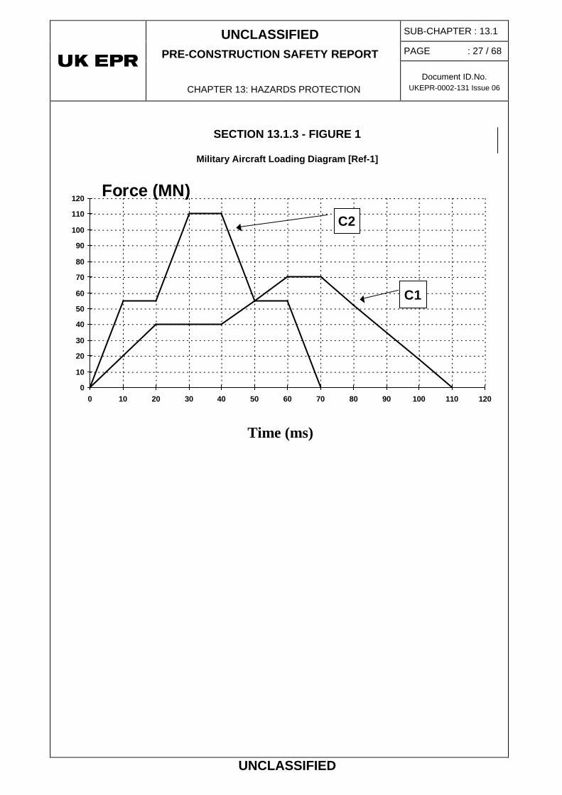
In order to design the protection structures in the aircraft shell type of protection, accidental aircraft impact is modelled via two load diagrams (force in relation to time) - C1 and C2 [Ref-1] shown in Section 13.1.3 - Figure 1.
The purpose of these load diagrams (C1 and C2) is to represent two types of effect: firstly, a local perforation caused by the impact and secondly, a more general effect of vibrations experienced in the buildings. They are applied in the following ways:
• The C1 curve is used for the design of the internal structures in the buildings in relation to the vibrations experienced. By utilising the linear elastic behaviour of the material and the different points of impact of an aircraft on each external protection wall, the response spectrum is deduced and used to design the relevant equipment. The separation of the internal structures and the external walls of the buildings, which receive the impact, reduce the stress on the equipment to be protected.
• The C2 curve represents impact on a rigid target and is used to verify the final local resistance to perforation of the external walls with a reduced margin. The corresponding safety demonstration may be based on the existence of walls located beneath the aircraft shell in the protected buildings.

UNCLASSIFIED PRE-CONSTRUCTION SAFETY REPORT
CHAPTER 13: HAZARDS PROTECTION
SUB-CHAPTER : 13.1
PAGE : 26 / 68
Document ID.No. UKEPR-0002-131 Issue 06
UNCLASSIFIED
3.2. PROTECTION AGAINST MALICIOUS AIRCRAFT CRASH
The UK Safety Authority has provided specific guidance to the GDA Requesting Parties on the protection measures that should be provided against malicious Air Plane Crash (APC) on new build reactors, such as the UK EPR.
A safety case for the UK EPR APC protection has been developed (SNI classified information) which demonstrates that the UK requirements are met. This safety case presents the safety claims made on the APC protection, and provides arguments that they are achieved by the design, concluding that no additional design measures are necessary to protect the UK EPR from an APC (accidental or malicious).
UNCLASSIFIED PRE-CONSTRUCTION SAFETY REPORT
CHAPTER 13: HAZARDS PROTECTION
SUB-CHAPTER : 13.1
PAGE : 27 / 68
Document ID.No. UKEPR-0002-131 Issue 06
UNCLASSIFIED
SECTION 13.1.3 - FIGURE 1
Military Aircraft Loading Diagram [Ref-1]
0
10
20
30
40
50
60
70
80
90
100
110
120
0 10 20 30 40 50 60 70 80 90 100 110 120
C2
C1
Force (MN)
Time (ms)
UNCLASSIFIED PRE-CONSTRUCTION SAFETY REPORT
CHAPTER 13: HAZARDS PROTECTION
SUB-CHAPTER : 13.1
PAGE : 28 / 68
Document ID.No. UKEPR-0002-131 Issue 06
UNCLASSIFIED
4. PROTECTION AGAINST THE HAZARDS ASSOCIATED WITH THE INDUSTRIAL ENVIRONMENT AND TRANSPORT ROUTES - EXTERNAL EXPLOSION
4.1. SAFETY REQUIREMENTS AND DESIGN BASIS
4.1.1. Identification of Hazards
Industrial installations and transport routes which may pose a hazard to the plant are identified for in site specific studies. The hazards to be considered are:
• Explosion: compression wave, ground movements, missiles, etc.
• Off-site Fire: thermal radiation, smoke.
• Movement of toxic, corrosive or radioactive gases.
Three groups of hazard sources are considered:
• Fixed industrial installations, such as storage or production installations.
• Oil or gas networks.
• Road, rail, river or maritime transport routes.
Aircraft impact is covered in section 3 of this sub-chapter.
4.1.2. Applicable Regulations - Basic Safety Regulations - Technical Guidelines- Codes - Standards
The applicable regulations, codes and standards are identified in Sub-chapter 1.4.
With regard to the hazards associated with the industrial environment and transport routes, the general safety objectives are those which are associated with the external hazards and which are explained in the Technical Guidelines A2.5. The design cases to be used are defined in Technical Guidelines F2.2.3: "With regard to external explosions, design of the next generation of nuclear power plants must take into consideration, as a standard load over time, a triangular shaped pressure wave with a vertical leading edge and a maximum over-pressure of 100 mbar and a duration of 300 ms. This means that, given the possible reflections on the walls and roofs of the buildings, the load over time on the building walls will consist of a maximum pressure wave of 200 mbar on the flat walls". The EPR safety objectives are more restrictive than those described in French regulations, and the design loading cases are greater than those in French regulations.
Additionally the design loading cases are comparable with (and in fact more onerous than) that presented in IAEA standard NS-G-1.5 [Ref-1] which is a triangular shaped pressure wave with a vertical leading edge and a maximum over-pressure of 100 mbar and a duration of 200 ms, based on Unified Facilities Criteria UFC 3-340-02 [Ref-2].

UNCLASSIFIED PRE-CONSTRUCTION SAFETY REPORT
CHAPTER 13: HAZARDS PROTECTION
SUB-CHAPTER : 13.1
PAGE : 29 / 68
Document ID.No. UKEPR-0002-131 Issue 06
UNCLASSIFIED
4.1.3. General Principles
The design takes into consideration the external explosion hazard based on Technical Guideline F.2.2.3. A case-by-case analysis is performed for drift of gas clouds (toxic, corrosive or radioactive) using a defined methodology [Ref-1] and, where necessary, design measures are adopted for protection against this hazard (by design of suitable closed circuit ventilation systems or filtration).
Plant design in relation to the external explosion hazard uses a loading case which is referred to as an explosion Compression Wave. It is included in the design of the following buildings (see Sub-chapter 3.3):
Security Sensitive material removed from this version of the report.
4.1.4. Design Parameters
The standard loading case which is representative of the incident wave, used for design, is a Security Sensitive material removed from this version of the report It represents a detonation wave. The detonation is expected to occur at the accident location, i.e. at a transport route or a fixed industrial installation. The benchmark wave is expected to arrive in a horizontal direction.
Security Sensitive material removed from this version of the report.

UNCLASSIFIED PRE-CONSTRUCTION SAFETY REPORT
CHAPTER 13: HAZARDS PROTECTION
SUB-CHAPTER : 13.1
PAGE : 30 / 68
Document ID.No. UKEPR-0002-131 Issue 06
UNCLASSIFIED
Security Sensitive material removed from this version of the report.
4.2. DESIGN VERIFICATION
The objective of the design verification is to evaluate, for each accident scenario, the safe distance, beyond which a potential explosion will not threaten any basic safety function, because the consequential pressure wave is lower than the design load case. This evaluation assumes worst case meteorological conditions for the explosive gas cloud drift before the explosion.
Where this deterministic approach does not allow the risk from external explosion to be excluded, a probabilistic assessment is carried out.
A first qualitative probabilistic assessment is presented in Sub-chapter 15.2.

UNCLASSIFIED PRE-CONSTRUCTION SAFETY REPORT
CHAPTER 13: HAZARDS PROTECTION
SUB-CHAPTER : 13.1
PAGE : 31 / 68
Document ID.No. UKEPR-0002-131 Issue 06
UNCLASSIFIED
SECTION 13.1.4 - FIGURE 1
Standard load-time function for Explosion Pressure Wave
This figure contains Security Sensitive material that has been removed from this version of the report.
UNCLASSIFIED PRE-CONSTRUCTION SAFETY REPORT
CHAPTER 13: HAZARDS PROTECTION
SUB-CHAPTER : 13.1
PAGE : 32 / 68
Document ID.No. UKEPR-0002-131 Issue 06
UNCLASSIFIED
5. PROTECTION AGAINST EXTERNAL FLOODING
5.1. SAFETY REQUIREMENTS
5.1.1. Safety Objectives
Following an external flooding event, the basic objectives are:
• Maintaining the integrity of the primary system,
• Tripping the reactor and removing the decay heat,
• Limiting any possible release of radioactive substances to an acceptable level.
5.1.2. External Flooding Safety Requirements
The requirements related to the protection against external flooding are to:
• Keep the buildings housing safety classified equipment dry, by setting the platforms at a level at least equal to the Maximum Design Flood Level.
• Prevent as far as possible any water present on the platforms from flowing into these buildings.
The different external flooding hazards that are taken into account are described below, along with additional cases of combinations.
The detailed design of the UK EPR to withstand external flooding is site-dependent: therefore the application of the design process and safety analysis will not be provided in the framework of the GDA.
5.1.2.1. Hazards taken into account in external flooding protection
The area around the site will be evaluated to determine the potential for flooding due to the following hazards:
• Exceptional Coastal Flooding: this accounts for a combination of high tide and events like storm surge, barometric effects and seiche.
• Tsunami: this high-amplitude wave is created following a landslide or an undersea earthquake and is considered to be covered by the Exceptional Coastal Flooding.
• Exceptional Estuary Flooding: it accounts for a combination of high tide, river flood, events like storm surge, barometric effect and seiche, upstream dam rupture or failure.
• High Waves: this hazard includes all the surface waves.

UNCLASSIFIED PRE-CONSTRUCTION SAFETY REPORT
CHAPTER 13: HAZARDS PROTECTION
SUB-CHAPTER : 13.1
PAGE : 33 / 68
Document ID.No. UKEPR-0002-131 Issue 06
UNCLASSIFIED
• Deterioration of water channel structures: this concerns risks related to a possible deterioration of structures (such as canal embankments, reservoir ponds, water retainers, tanks of air coolant towers) located near the site and located at a level higher than the site platform. This hazard is analysed considering a certain number of potential load cases (earthquake, explosion, airplane crash, hydraulic deterioration, etc.). This hazard is characterised by the quantity of water potentially released and the maximum flow rate resulting from the deterioration, as well as the dynamics of the phenomenon.
• Break of Systems or Equipment: this hazard is characterised by the amount of water released by the break taking into account the specific flow rate of the opening and the event, until isolation of the flow (manually, automatically, etc.).
• Swell: a malfunction of isolation valves (e.g. valves located on the inlet channel of a hydroelectric plant, the sudden stoppage of a Service Water pump, etc.) can cause strong variations in the water level, which may flood certain installations located upstream (or even downstream). The "Swelling" hazard is characterised by the maximum overflow rate or the maximum corresponding height on the site, as well as the duration of the fast dynamic phenomenon.
• Brief Heavy Rainfall: this hazard is characterised by the maximum average intensity parameter. This intensity corresponds to the maximum amount of water that falls during a relatively short period. It characterises the violence of the initial phase of a storm.
• Long Heavy Rainfall: this hazard is characterised in the same way, but using daily maximum average intensities.
• Rise in Groundwater: this hazard is characterised by the evaluation of the water table level and the speed of change.
5.1.2.2. Additional cases of flooding hazard combinations
Additional combinations have been identified and are to be considered in the safety analysis. The selected combinations are such that their frequency is of the same order of magnitude as the Exceptional Coastal Flooding.
These various combinations are first defined for the hazards which have a certain level of dependency. However in some instances they may be defined by convention even though the combined hazards are considered to be relatively independent.
For coastal sites or sites in estuaries:
• Exceptional Coastal Flooding combined with a hundred-year High Waves.
• Exceptional Estuary Flooding combined with a hundred-year High Waves,
• A hundred-year Coastal flooding combined with a hundred-year Long Heavy Rainfall,
• Exceptional Coastal Flooding combined with a ten-year Long Heavy Rainfall of 24 hours (as part of defence in depth),
• Exceptional Flooding, Coastal or Estuary, combined with Swell,

UNCLASSIFIED PRE-CONSTRUCTION SAFETY REPORT
CHAPTER 13: HAZARDS PROTECTION
SUB-CHAPTER : 13.1
PAGE : 34 / 68
Document ID.No. UKEPR-0002-131 Issue 06
UNCLASSIFIED
• Exceptional Flooding, Coastal or Estuary, combined with groundwater at the maximum historical level,
Other combinations:
• External flooding combined with a Loss Of Off-site Power (for certain sites LOOP of 1 day to 3 days, according to sites),
• External flooding combined with an additional loss of heat sink situation.
5.2. DESIGN BASIS
The design of the facility includes adequate provision for the collection and discharge of water reaching the site from any design basis external flooding hazard. Where this is not achievable, the structures, systems and components important to safety will be adequately protected against the effects of water. Such measures include:
• Setting of the platform level and volumetric protection,
• Fixed or mobile protection devices,
• Design of a suitable water drainage system,
• Design of rockfill embankment or seawall protection able to withstand High Waves.
5.2.1. Setting of the Platform level and volumetric Protection
5.2.1.1. Classified Civil Engineering Structures
The platform level bounds the Maximum Safety Water Level (MSWL) which basically covers the Exceptional Coastal Flooding hazard.
In terms of defence in depth, and in order to control any risk associated with transient overflows or limited failures of protection devices, volumetric protection is implemented for:
• The lower parts of buildings housing safety classified structures and equipment up to the MSWL, increased by a margin to allow for current expected climate change effects.
• Increased as a general rule to the site platform (0.0m) level,
This procedure is applied to the nuclear island rooms, the main circulating water tunnels and the Pumping Station.
5.2.1.2. Other Buildings or Equipment
Non-classified plant is protected from flood water corresponding to the known historical maximum flood level or the highest known tides. In theory, this position could imply the setting the site platform at a lower level than that of the nuclear island platform. However, in practice, for commercial and design reasons, the site platform level is generally set at the same level as the nuclear island platform.

UNCLASSIFIED PRE-CONSTRUCTION SAFETY REPORT
CHAPTER 13: HAZARDS PROTECTION
SUB-CHAPTER : 13.1
PAGE : 35 / 68
Document ID.No. UKEPR-0002-131 Issue 06
UNCLASSIFIED
5.2.2. Protection Devices
The fixed protection devices are principally barriers for coastal (and estuary) sites, taking into account wave effects.
Mobile protection devices may be used if their effectiveness has been demonstrated and adequate robustness is assured.
The design procedures for protection against external flooding are divided into three stages:
1. Design of protection based on the hazards, characterised in a conservative manner;
2. Elevation of safety classified equipment to levels above the Maximum Safety Water Level (MSWL) with an added height margin to allow for climatic changes expected in the medium term;
3. Verification that the margins are adequate for the functioning of all associated systems.
In addition, when more precise assessments of the long term climatic developments become available and, as a minimum during the ten-yearly periodic safety reviews, site vulnerability to all aspects of external flooding will be re-examined.
5.2.3. Design of the Water Drainage Network
Rainwater is, most of the time, drained by gravity. The water drainage system is designed on the basis of Long Heavy Rainfall levels considering the combination with an Exceptional Coastal (or Estuary) Flooding. Design of the water drainage system is part of the site engineering, and therefore outside the scope of the GDA.
5.3. DESIGN VERIFICATION
The general methodology which was updated after the incident at the Blayais Nuclear Power Station in 1999 is used to confirm that the risk of external flood is acceptable [Ref-1].
The detailed design being site-dependent, the application of the design process and safety analysis will not be provided in the framework of the GDA.

UNCLASSIFIED PRE-CONSTRUCTION SAFETY REPORT
CHAPTER 13: HAZARDS PROTECTION
SUB-CHAPTER : 13.1
PAGE : 36 / 68
Document ID.No. UKEPR-0002-131 Issue 06
UNCLASSIFIED
6. PROTECTION AGAINST EXTREME CLIMATIC CONDITIONS
6.1. SAFETY REQUIREMENTS
6.1.1. Safety objectives
The objectives for protecting against extreme climatic conditions are to prevent or reduce any resulting adverse effects and to limit possible radioactive releases.
Within the design procedure, this involves ensuring that satisfactory ambient conditions are maintained for those systems where failure is likely to adversely affect the following safety functions:
• Integrity of the primary cooling system,
• Shutdown of the reactor and removal of decay heat,
• Limiting possible release of radioactive substances on the site to an acceptable level.
The design climatic values of the UK EPR are defined at GDA level for a “cold seaside plant” of the same type as most potential UK coastal sites. Unless mentioned specifically, all generic structures and equipment are designed using these values. During NSL, site specific climatic conditions are taken into consideration when designing the site specific structures and equipment.
6.1.2. Protection against snow and wind
All of the civil engineering structures are designed in accordance with the appropriate "Snow and Wind1
6.1.3. Protection against wind generated missiles
" design codes [Ref-1] [Ref-2].
Any potential missiles which are likely to cause a threat to other structures or materials must be considered.
The following equipment located outside of the buildings is protected against missiles which are likely to be generated by high wind at the level considered in the design of the installation:
• F1 classified,
• F2 classified, required to return the unit to a safe shutdown state as defined in Sub-chapter 3.2, including Loss Of Off-site Power (LOOP) or total loss of the main heat sink, as well as the combination of LOOP + total loss of the main heat sink.
1 That is, the Eurocodes (and in particular Eurocode 1) which are due to supersede, amongst others, BS 6399 Part 2 (Wind Loadings) and Part 3 (Imposed Roof Loads).

UNCLASSIFIED PRE-CONSTRUCTION SAFETY REPORT
CHAPTER 13: HAZARDS PROTECTION
SUB-CHAPTER : 13.1
PAGE : 37 / 68
Document ID.No. UKEPR-0002-131 Issue 06
UNCLASSIFIED
In addition, it is necessary to ensure that damage caused by missiles (possibly multiple) on external equipment (tanks, pipes, gas systems, etc) which is located on the platform is not likely to affect equipment which is needed to return and maintain the installation to a safe condition (e.g. by causing a flooding risk or internal explosion) including a LOOP, or total loss of the main heat sink and the combination of LOOP + total loss of the main heat sink.
6.1.4. Protection against extreme low ambient temperature
6.1.4.1. Safety requirements
For the design basis low temperature conditions, the F1 and F2 equipment must be able to complete its functions.
Extreme Cold is considered to be a natural external hazard. Extreme Cold occurs when the temperatures fall below the temperature used for the design. The installation must be able to withstand any PCC-2 to PCC-4 situations which are combined with Extreme Cold.
To enhance defence in depth, other combinations are considered. These ensue that certain items of equipment are protected against Extreme Cold which are vital for management of RRC-A (prevention of core melt) situations involving loss of the ultimate heat sink or loss of electrical power supplies.
In addition, the equipment which must be protected against Extreme Cold is that which is required to return and maintain the installation to a safe shutdown condition and to limit the radiological consequences; even in a LOOP event (see next section).
However, certain specific instances are excluded:
• Equipment which is used in those conditions where the frequency of occurrence relates to the residual risk (notably, the combination of Extreme Cold + Loss of external power supplies + Accident)
However, the fire detection and fighting devices which are safety classified, must be available in periods of Extreme Cold.
Equipment which is vital for Extreme Cold management must be F2 classified. Depending on the case, we ensure either:
• The availability of the equipment. This equipment must be able to fulfil its function during the period of Extreme Cold, or
• The non-deterioration of the equipment. This equipment may not be able to fulfil its safety function during the period of Extreme Cold, but is subsequently functional on demand, once the Extreme Cold has ceased.
6.1.4.2. Consideration of the Loss Of Off-site Power Supplies (LOOP)
The loss of off-site power supplies is more likely to occur during a period of cold where the grid is subject to greater electrical loads.
It is therefore necessary to ensure that the reactor can be shut down and maintained in a safe shutdown condition following loss of grid. The demonstration must consider the equipment which is required during this operating condition and its ability to fulfil the required functions.

UNCLASSIFIED PRE-CONSTRUCTION SAFETY REPORT
CHAPTER 13: HAZARDS PROTECTION
SUB-CHAPTER : 13.1
PAGE : 38 / 68
Document ID.No. UKEPR-0002-131 Issue 06
UNCLASSIFIED
The other F1 and F2 classified equipment, which are required in periods of Extreme Cold in other operating conditions, must be available after the LOOP.
The postulated loss of off-site power in Extreme Cold conditions is assumed to be due to loss of grid and not an on site equipment failure.
It is necessary to consider both the situation where the station is initially in a shutdown condition and the situation where it is initially in an at-power state, and then is shutdown due to the loss of the external electric power supplies.
6.1.5. Protection against frazil ice and freeze-up
Two phenomena may occur during a cold spell: the appearance of a layer of ice on the surface and/or the formation of frazil ice (ice micro particles transported in suspension).
Three types of risk can be identified:
• Active frazil ice (equivalent to super cooling frazil ice): this has highly adhesive properties, which can cause blockage of the water inlet grills.
• Passive frazil ice: (relatively large plates which float with the water, and which are likely to be ingested by the water intake; or they may become stacked and cause "column" blocking): this has the ability to block the intake strainers.
• Freeze-up: this causes a reduction in the water flow area and may eventually obstruct the water intake by forming an ice cover.
The cooling water intakes must be protected from the possible effects of frazil (sea) ice and freeze-up.
6.1.6. Protection against high ambient temperatures
Three types of temperature are used in the design of the installation:
• Two temperatures for the air: a maximum daily average (Tdaily air max), and an instantaneous maximum (Tprompt air max)
• A temperature for the heat sink water: daily maximum.
Unless mentioned specifically, all of the standard structures and equipment are designed using the temperatures defined above. The site specific temperatures are taken into consideration when designing the site specific structures and equipment.
6.1.7. Protection against drought - very low heat sink water level
The cooling water intake structures are protected from the possible effects of drought.
For a coastal site, due account is taken of anticipated tidal condition, particularly during spring and autumn. Extreme low sea levels over a prolonged period (several days) are very unlikely.
Exceptional very low tide conditions occur during a combination of extreme meteorological and tidal conditions. Meteorological effects include atmospheric pressures and wind.

UNCLASSIFIED PRE-CONSTRUCTION SAFETY REPORT
CHAPTER 13: HAZARDS PROTECTION
SUB-CHAPTER : 13.1
PAGE : 39 / 68
Document ID.No. UKEPR-0002-131 Issue 06
UNCLASSIFIED
The following is considered for the FA3 EPR:
• Normal predicted (‘astronomical’) tidal variations with a maximum coefficient of 120.
• Additional effects caused by extreme atmospheric pressures variations and high wind. Characterisation of these effects is derived from statistical analysis of extreme events.
In the specific case of an estuary, the effect of combined marine and river influences must be considered.
6.2. DESIGN BASIS
As noted above, because of the uncertainties in the climatic parameters to be covered over the service life of the reactor, the initial design of the EPR reactor makes provision for enhancement during operation, to address potential realistic climatic developments beyond those initially considered.
As explained in this section, facilities for implementing these enhancements may be planned in three ways:
• Consideration at the design stage of additional margins with regard to the design cases used,
• Feasibility of installation of modifications,
• Acceptability of operational development.
6.2.1. Snow and wind
The buildings are designed in accordance with the relevant Eurocodes [Ref-1] [Ref-2].
The adaptability of the design of the installation to accommodate future climatic changes does not require a specific study for snow. Considering predicted climatic changes, cold weather conditions, including snow, are expected to be less severe in the future.
6.2.2. Wind generated missiles
Two types of missiles are considered [Ref-1]:
• Heavy missiles which are propelled along the ground,
• Light missiles which are considered at all heights and in all directions.
The maximum wind speed to be used for a specific site is as defined by the relevant Eurocodes.
In these conditions the missiles reach the following speeds. The maximum wind speed is site specific.

UNCLASSIFIED PRE-CONSTRUCTION SAFETY REPORT
CHAPTER 13: HAZARDS PROTECTION
SUB-CHAPTER : 13.1
PAGE : 40 / 68
Document ID.No. UKEPR-0002-131 Issue 06
UNCLASSIFIED
Missiles Dimension (m)
Mass (kg)
Maximum height (m) Speed
Automobile 3.8 x 1.5 x 1.3 900 0 3 m/s
Wooden board 3.7 x 0.3 x 0.09 50 Any height 50% of the maximum wind
speed
Cladding sheets 1 x 6 60 Any height Maximum wind speed
6.2.3. Low air temperatures [Ref-1]
The following three characteristic values are used for the design:
a) The minimum average temperature observed over more than 7 consecutive days,
b) The minimum average temperature over 24 hours,
c) The minimum instantaneous temperature (or three-hourly if instantaneous temperature is not available).
The previous temperatures are used to define the design spectrum as follows:
• The long duration temperature represents the conditions which could frequently occur and persist (normal and continuous operating conditions). It is thus assumed that this temperature may exist permanently.
• The short duration temperature is representative of a temperature which could only occur for periods limited both in terms of time and frequency. This defines the short duration temperature which is used in the design with duration of 7 days.
• The prompt (i.e. instantaneous) temperature is used instead of the short duration temperature for low thermal inertia items. This defines the temperature which is used in the design with duration of 6 hours.
For the design of the civil engineering structures the thermal stresses take into consideration the long duration temperature. The short duration temperature is used to design the ventilation systems and the protection against freezing.
Wind may have two effects:
Consideration of wind associated with cold conditions:
• Additional heat loss from walls and structures,
• High wind may have a detrimental effect on equipment housed in rooms which have openings.

UNCLASSIFIED PRE-CONSTRUCTION SAFETY REPORT
CHAPTER 13: HAZARDS PROTECTION
SUB-CHAPTER : 13.1
PAGE : 41 / 68
Document ID.No. UKEPR-0002-131 Issue 06
UNCLASSIFIED
However, it should be noted that available information indicates that periods of extreme cold are, most likely to be associated with conditions of low or no wind. As a general indication, a boundary occurs around values of –15°C. Below this temperature, wind is very unlikely to occur. The wind value used is 4 m/s.
A duration of 24 hours is conservatively assumed for the Loss Of Off-site Power in order to encompass the duration of the LOOP considered in PCC-3.
Temperature values used for the EPR are shown in the following table:
Type Long
duration temperature
Short duration temperature Prompt temperature
Temperature-duration rates
-15°C permanent +
wind (4 m/s) + LOOP
-25°C (7 days)
excluding LOOP
-25°C (7 days)
+ LOOP (24 h)
-35°C (6 h) + LOOP (24 h)
CONDITION OF EQUIPMENT TO MAINTAIN
F1 and F2 classified materials required during an LOOP
Available Available Available Available
Other (F1 and F2) "Extreme Cold"
systems not required during an LOOP
Available Available Not damaged Not damaged
The above temperatures will be compared with the relevant site condition temperatures.
The adaptability of the design of the installation to accommodate future climatic changes does not require a specific study for extreme cold. Considering predicted climatic changes, cold weather conditions are expected to be less severe in the future.
6.2.4. Frazil ice and freeze-up
Provisions are implemented for the cooling water intake structures in order to protect against the risk of a loss in the heat sink caused by frazil ice or freeze-up.
The adaptability of the design of the installation to accommodate future climatic changes does not require a specific study for frazil ice. Considering predicted climatic changes, cold weather conditions are expected to be less severe in the future.

UNCLASSIFIED PRE-CONSTRUCTION SAFETY REPORT
CHAPTER 13: HAZARDS PROTECTION
SUB-CHAPTER : 13.1
PAGE : 42 / 68
Document ID.No. UKEPR-0002-131 Issue 06
UNCLASSIFIED
6.2.5. High ambient temperature [Ref-1]
6.2.5.1. Air temperatures and associated relative humidity (HR)
Tdaily air max
- Air temperatures with associated relative humidity for buildings with high thermal inertia: average over 12 hours.
Cold seafront values
Tdaily air max = 36°C
HR = 40 %
T prompt air max
- Air temperatures with associated relative humidity for buildings with low thermal inertia: prompt (instantaneous).
Cold seafront values
T prompt air max = 42°C
HR = 29 %
6.2.5.2. Maximum heat sink temperature
For the cold coastal alternative criterion, the maximum temperature used for the overall heat sink is 26°C.
6.2.6. Drought - very low heat sink water level
The cooling water intake structures are protected from the possible effects of drought by siting and designing them to the Lowest Safe Water Levels (LSWS). Thus, the plant is protected against the risk of a loss of the heat sink during a drought or more generally during very low water level events.
For a coastal site, the adaptability of the installation in relation to the climatic developments for drought does not require a specific study. In practice, the anticipated situation is an increase in sea level.

UNCLASSIFIED PRE-CONSTRUCTION SAFETY REPORT
CHAPTER 13: HAZARDS PROTECTION
SUB-CHAPTER : 13.1
PAGE : 43 / 68
Document ID.No. UKEPR-0002-131 Issue 06
UNCLASSIFIED
6.2.7. Durations for Loss of Ultimate Heat Sink and Loss Of Off-site Power
Loss of the ultimate heat sink and loss of off-site power supplies, as well as their combined effect are considered to be a plausible consequence of extreme climate related external hazards.
The following overall durations are used:
Elementary situations for the whole site
Case LOOP site Loss of site ultimate heat sink Alert phase
LOOP only 15 days (*)
Loss of site ultimate heat sink 100 hours 24 hours
Combined
LOOP + loss of ultimate heat sink 8 days 24 hours 24 hours
(*) The 15 day duration for the LOOP is used in consideration of an earthquake and envelopes the expected durations of external hazards which are of climatic origin.
Safe shutdown and maintenance of a safe shutdown state are assured in the different periods indicated in the above table.
6.3. DESIGN VERIFICATION
The detailed design for extreme climatic conditions being site-dependent for a significant number of systems, the corresponding studies are not provided in the framework of the GDA.
6.3.1. Resistance to snow and ice
All safety and non-safety classified buildings are designed to withstand the effects of snow and ice loads.
6.3.2. Resistance to wind
All buildings and external equipment are designed to withstand the effects of wind. Hence, all F1 and F2 safety classified equipment is protected against the direct mechanical and aerodynamic effects of wind.
The safety classified ventilation systems are designed to withstand the aerodynamic effects of wind.

UNCLASSIFIED PRE-CONSTRUCTION SAFETY REPORT
CHAPTER 13: HAZARDS PROTECTION
SUB-CHAPTER : 13.1
PAGE : 44 / 68
Document ID.No. UKEPR-0002-131 Issue 06
UNCLASSIFIED
6.3.3. Protection against wind generated missiles
The external F1 classified equipment and the F2 classified equipment which is required to shut down the reactor and maintain it in a safe state, including during a LOOP, a loss of heat sink and during a combined LOOP + loss of heat sink, are protected from potential wind generated missiles.
6.3.4. Protection against extreme cold
A thermal assessment is undertaken for each site building or installation, for the different plant states, to determine the ambient temperature of the rooms containing equipment to be qualified for Extreme Cold conditions [Ref-1].
This assessment is undertaken on the basis of the site temperatures for the site specific structures and equipment.
6.3.5. Protection against frazil ice and freeze-up
Frazil ice is a site-dependent phenomenon. Based on a site specific analysis, this phenomenon could be considered as relevant for this specific site. In that case, some design features could be implemented to protect the system filters from clogging or to prevent the frazil ice from happening.
More generally, the risk of clogging in the system filters is very unlikely considering the over sizing of the filtering surface of the drum screen and the chain filters in relation to the SEC (ESWS) safety flow rate.
The elevation of the cooling water pumps allows for an appropriate maximum ice thickness.
6.3.6. Protection against high ambient temperature
Unless specifically stated, the civil engineering structures and the ventilation and air conditioning systems are designed to accommodate the high ambient temperatures given in section 6.2.5.
The maximum temperature of the heat sink is used for the design of the cooling systems. In order to include additional margins in the EPR design to allow for possible climate change, PCC-2 to PCC-4 analyses use a heat sink temperature of 30°C (see Sub-chapter 2.1 and Sub-chapter 9.2, sections 1 and 2)
6.3.7. Protection against drought or very low heat sink water level
The choice of, and design against, the Lowest Safety Water Level (LSWL) for the cooling water intakes ensures that loss of heat sink will be avoided in the event of drought or very low heat sink water level [Ref-1]. Additional operating measures could be in force such as bathymetry and periodic dredging.

UNCLASSIFIED PRE-CONSTRUCTION SAFETY REPORT
CHAPTER 13: HAZARDS PROTECTION
SUB-CHAPTER : 13.1
PAGE : 45 / 68
Document ID.No. UKEPR-0002-131 Issue 06
UNCLASSIFIED
7. PROTECTION AGAINST LIGHTNING AND ELECTROMAGNETIC INTERFERENCE
7.1. SAFETY REQUIREMENTS
The general objective of the design provisions is to ensure that the safety functions of the systems and components which are required to bring the plant to a safe shutdown state and to prevent and limit radioactive releases, are maintained.
Finally, equipment which is required to function during external events must be qualified for the range of parameters assumed to occur during such events.
7.1.1. Consideration of Combined Events
A combination of lightning is envisaged with fire, internal explosion and heavy rain:
• All F2 classified fire protection will be protected against the effects of lightning;
• Taking the risk of lightning into account should not challenge the safety demonstration developed for the risk of internal explosion;
• Lightning will not affect the capacity of the rain water drainage system to cope with heavy rain.
7.1.2. Classification
These requirements are reflected by the following objectives:
• F1 or F2 classified equipment will be protected against lightning;
• Civil engineering structures with safety class 1 will retain their containment function;
• The lightning protection systems, whose life is limited in relation to the life of the unit and is dependent on stresses due to lightning (e.g. surge protective device) will be classified F2.
7.2. DESIGN BASIS [REF-1]
7.2.1. Characterisation of the Hazard
7.2.1.1. Severity of lightning strike on nuclear sites
The severity of lightning strike is defined as the density of lightning strikes on the ground expressed as the number of strikes/km2/year.

UNCLASSIFIED PRE-CONSTRUCTION SAFETY REPORT
CHAPTER 13: HAZARDS PROTECTION
SUB-CHAPTER : 13.1
PAGE : 46 / 68
Document ID.No. UKEPR-0002-131 Issue 06
UNCLASSIFIED
7.2.1.2. Occurrence probability
Lightning is a climatic event, whose probability of occurrence is high relative to other external hazards i.e. it is of the order of magnitude of Plant Condition Category 2 (PCC-2).
7.2.1.3. Characteristics of the lightning current
The lightning characteristics assumed are related to level I protection as defined by the standard IEC 62 305 sections 1 to 4.
Characteristics of lightning Level I of protection
First stroke
Value of the peak current 200 kA
Front time 10 µs
Time to half value 350 µs
Impulse charge 100 C
Specific energy W/R 10MJ/Ω
Subsequent strokes
First return arc peak 50 kA
Front time T1 0.25 µs
Time to half value T2 100 µs
average dI/dt with Imax 200 kA/µs
Long duration stroke Maximum charge 200 C
Duration T 500 ms
Characteristics of the lightning current assumed for level I protection
The frequency range of the lightning electromagnetic hazard is between 0 and 1 MHz.
7.2.1.4. Electro Magnetic Interference
The electromagnetic environment of power stations is defined according in the IEC 61000-6-5 Standard. The electromagnetic interference induced by lightning hazard is considered as the sizing case for protection requirements. As regards electrical and I&C equipment immunity, (Electro Magnetic Compatibility – EMC) see Sub-chapter 8.4.

UNCLASSIFIED PRE-CONSTRUCTION SAFETY REPORT
CHAPTER 13: HAZARDS PROTECTION
SUB-CHAPTER : 13.1
PAGE : 47 / 68
Document ID.No. UKEPR-0002-131 Issue 06
UNCLASSIFIED
7.2.2. Consequences of a Lightning Strike
The main consequences of the lightning strike on a structure are set out below.
Building orequipmentstruck bylightning
Transmission toearthing circuits vialightning conductors
Rise in potential
Destruction/Malfunction ofelectrical and
electronic equipment
Transmission viaelectrical power
lines
Transmission vialow current lines
Induction ofelectrical lines
Highinduction
Arc effect
Acoustic effectsnoise
Mechanicaldestruction
FireExplosion
Temperaturerise
Highresistance
Flashover
Direct effectsIndirect effects
Step voltageHuman risk
Radiation
Consequences of lightning strike on a structure.
The direct and indirect effects contribute to the consequences, which may be:
• Malfunctions in the electrical and electronic systems;
• Destruction of electrical, electronic and mechanical equipment, damage to non-conducting structures;
• Risks of electrification or even electrocution;
• The outbreak of fire or even explosion.
Additional unwanted effects could be:
• Automatic Shutdown of the Reactor;
• Unwanted start up of safety systems;
• Unavailability of safety systems;

UNCLASSIFIED PRE-CONSTRUCTION SAFETY REPORT
CHAPTER 13: HAZARDS PROTECTION
SUB-CHAPTER : 13.1
PAGE : 48 / 68
Document ID.No. UKEPR-0002-131 Issue 06
UNCLASSIFIED
• Loss of fire protection system.
To satisfy the safety requirements, nuclear power plants must be protected from the direct and indirect effects of lightning.
7.2.2.1. Direct effects
The direct effects of lightning are thermal, mechanical or electrical (step change in voltage and electrification of objects/equipment). The magnitude of these effects is a function of the energy of the lightning strike.
7.2.2.2. Indirect effects
The indirect effects on equipment are due to the:
• direct electromagnetic radiation of the lightning ;
• overvoltages generated, by conduction or induction, in the cables and lines and which may disrupt operation.
The source of the electromagnetic field is the current of the return arc of the lightning discharge and, in particular, the steepness of the wave front.
7.2.3. Protection Principle
Standard industry practice for lightning protection is as follows:
• Channelling the lightning current and discharging it to earth by a short circuit;
• Ensuring the equipotential bonding of the installation;
• Limiting and if necessary discharging the residual overvoltage wave.
To reach these objectives, the equipment must be protected by:
• The structure of the buildings in which they are housed and the earthing system to which the buildings and the grounding network are connected;
• The quality of the local grounding network and the various forms of attenuation of disturbances due to conduction and electromagnetic radiation in different rooms;
• The resistance of sensitive equipment, the effects of shock waves and electromagnetic hazards.
7.2.4. Design Requirements
7.2.4.1. Protection of equipment and buildings that contribute to the safety objectives against the direct effects of lightning
Good protection against the direct effects of lightning involves the control of the attraction and discharge of the lightning current. This protective device is made up of three main parts:

UNCLASSIFIED PRE-CONSTRUCTION SAFETY REPORT
CHAPTER 13: HAZARDS PROTECTION
SUB-CHAPTER : 13.1
PAGE : 49 / 68
Document ID.No. UKEPR-0002-131 Issue 06
UNCLASSIFIED
• Attraction devices (meshed cage or lightning conductor);
• The lightning conductor designed to discharge the lightning current to the ground;
• The earthing system designed to dissipate the lightning current in the ground.
7.2.4.1.1. Capture devices
The form of protection adopted for buildings and equipment, is that provided by a mesh cage (Faraday cage). The use of simple lightning conductors is reserved for buildings without metal structures.
The mesh must be provided by the conducting civil engineering structures of the various buildings to form Faraday cages:
• For buildings made of reinforced concrete: use of equipotential grids taking into account the rules for electrical continuity between the grids and with the earthing system;
• For steel structure buildings: use of the entire structure taking into account of the rules for electrical continuity between the grids and with the earthing system.
7.2.4.1.1.1. Level of protection of equipment and buildings that meet the safety objectives
F1 or F2 classified equipment will have level I protection (the highest level of protection under the terms of IEC 62305-1).
Civil engineering structures with safety class 1 and protected by FARADAY cages (reinforced concrete or steel structures) will have at least level II protection.
If safety class 1 buildings have a steel structure, their design will satisfy the requirements of IEC 62305-3 and the thickness of the metal sheets will not be less than the value t of table 3 of this standard.
The civil engineering structures with safety class 1 and protected by lightning conductors (buildings without metal structures) must have level I protection.
7.2.4.1.1.2. Protection by screen room
To meet the levels of protection required, the design of buildings should satisfy the following requirements:
Level of protection Civil engineering mesh (m) I 5 x 5 II 10 x 10
The mesh must be supported by the conducting civil engineering structures (reinforced concrete or steel structures) used as natural components, in accordance with standard IEC 62 305-3.
Furthermore, for reinforced concrete structures to be considered as structures that ensure electrical continuity, they should satisfy the following structural provisions:

UNCLASSIFIED PRE-CONSTRUCTION SAFETY REPORT
CHAPTER 13: HAZARDS PROTECTION
SUB-CHAPTER : 13.1
PAGE : 50 / 68
Document ID.No. UKEPR-0002-131 Issue 06
UNCLASSIFIED
• Most of the interconnections between vertical and horizontal bars are welded or secured soundly;
• Vertical bars are welded, pressed or superimposed with a minimum overlap of 20 times their diameter or secured soundly;
• The electrical continuity of the reinforcement of concrete (including prefabricated reinforced concrete structures) between the uppermost part and earth should be checked. The value of the total electrical resistance should not exceed 0.2 Ω DC.
If buildings have metal façades they should be constructed to ensure the electrical continuity of the whole building and must be connected to the rest of the civil engineering structure in accordance with the requested step required by the level of protection of the building.
All civil engineering structures should be interconnected (interconnection of the civil engineering structures with trenches, galleries, etc.). Any electrical discontinuity in the civil engineering structure, such as expansion joints should be eliminated (bridging using equipotential bonds at least every 2 m).
All components likely to contribute to the equipotential bonding and reinforcement of the Faraday cage: hand rails, ladders, guard rails, piping, ventilation ducts, etc., should be connected to the earthing system and grounding network.
7.2.4.1.1.3. Other protection
F1 and F2 classified equipment installed outdoors and not covered by the protection of buildings (use of the rolling sphere method), will be protected by individual protection systems, in accordance with IEC 62 305-3 (ground wire, simple lightning conductor, etc.).
Level of protection Radius of the rolling sphere R (m) I 20 II 30
7.2.4.1.2. Down conductors
The lightning current is directed to the earth by low impedance bonds meshed together and to the internal grounding network of the building. The down conductors carrying the lightning current will be at a maximum spacing of 10 metres;
The civil engineering structures providing protection for equipment that is important for safety are connected to the earthing system every 10 m. All buildings are connected to the buried network by at least two bonds.
Note: In order to ensure an effective connection between the civil engineering structure and the foundation’s earthing system, the Faraday cage formed by the civil engineering structure is connected to the building’s earthing system by equipotential bonding conductors. The equipotential bonds remain visible after the construction of the building.

UNCLASSIFIED PRE-CONSTRUCTION SAFETY REPORT
CHAPTER 13: HAZARDS PROTECTION
SUB-CHAPTER : 13.1
PAGE : 51 / 68
Document ID.No. UKEPR-0002-131 Issue 06
UNCLASSIFIED
7.2.4.1.3. The earthing system
7.2.4.1.3.1. Objectives of the earthing system
With regards to the lightning current, the earthing system is designed to:
• Redirect the disturbance (lightning current) from sensitive equipment by providing a preferential route for discharging the current to the ground;
• Control the voltage gradient by ensuring the equipotential bonding of the site.
7.2.4.1.3.2. Design of the earthing system
To ensure good equipotential bonding, the earthing system is meshed and interconnected. All meshes are connected to the rest of the network by at least 2 bonds. The network is buried at a depth of more than 1 m to protect it from the potential effects of frost. The conductors may be buried under the foundation raft provided that they are not surrounded by concrete (the bare conductor must be in direct contact with the ground). The route of the network is defined both under and outside the site coverage of the buildings. It takes the form of a rectangular mesh with a length to width ratio of between 1 and 3 and the largest dimension being less than 15 m. The different branches of the buried network are interconnected at points known as network nodes. The nodes of the network are robust using proven techniques to ensure the longevity of the connection (note: Thermit Welding process satisfies these requirements).
The mechanical stresses induced by dynamic loads associated with roads, railway lines etc are taken account of in the design of the buried network.
Potential sources of corrosion of the networks are analysed and the proposed mitigating measures to ensure the functions of the earthing system without replacement for the life of the installation (operating life + dismantling time). Hence, the properties of the materials used for the buried network and the risks of electrolytic corrosion in the presence of materials in the soil will be analysed (the electrolytic potential should be less than 300 mV at 20°C). Experience feedback on the behaviour of the material in various types of ground and associated chemical conditions, is provided by the Manufacturer.
The route of the earthing system is validated by a low and high frequency behavioural study.
7.2.4.1.3.3. Geological soil study
A study of the geological nature and structure of the soil will be carried out by studying the variation of its electrical resistance with depth. For extensions to the site, the initial soil studies are used. The characteristics of the soil, together with their annual variations and the nature of the geological strata will be determined, including the thickness, particle size analysis, electrical resistance and humidity. The chemical nature of the soil will be determined and, in particular, its corrosiveness (by the pH level). These investigations are carried out at depths corresponding to the depth at which the network is buried i.e. between –2.00 m and –15.00 m relative to site datum. The method used to determine the characteristics of the soil is the “four electrode” resistance method, wherever possible.
UNCLASSIFIED PRE-CONSTRUCTION SAFETY REPORT
CHAPTER 13: HAZARDS PROTECTION
SUB-CHAPTER : 13.1
PAGE : 52 / 68
Document ID.No. UKEPR-0002-131 Issue 06
UNCLASSIFIED
7.2.4.2. Equipment and installation protection against lightning indirect effects
The indirect effect of lightning is overvoltage caused by conduction or electromagnetic radiation. This is likely to disrupt the operation of sensitive equipment. Accordingly, sensitive equipment will be protected against disturbances arising from electromagnetic radiation and conduction.
Installations are protected against the indirect effects of lightning in accordance with trade practices for the protection of the installations and sensitive equipment against the indirect effects of high frequency electromagnetic disturbances defined in IEC 61000-5-2.
7.2.4.2.1. Protection against disturbances due to electromagnetic radiation
The principle of protection is based on the attenuation of radiated electromagnetic fields by:
• Subdivision and distribution of the flow of lightning current (via the structure of the building);
• Taking obstacles (wall, reinforcement, etc.) into account;
• Installation of shielding (reduction of the influence of low frequency electrical fields);
• Reduction of the ground loops (reduction of the influence of low frequency magnetic fields).
Protection against disturbances due to radiation is therefore based on the distribution of the flow of lightning current, shielding of the installations and the type of wiring.
Protection is provided by:
7.2.4.2.1.1. Devices used to capture and direct the lightning current towards the earthing system
Initial attenuation of disturbances due to electromagnetic radiation is obtained by subdividing the lightning current, using the different paths offered by the structure (protection by natural components) or by the existence of several down conductors (external protection).
7.2.4.2.1.2. Natural shielding formed by the structure of the buildings
The presence of obstacles, such as the walls, doors, and gratings provides natural shielding against the propagation of electromagnetic fields generated by lightning.
Furthermore, in the case of rooms housing sensitive equipment, the mesh in the civil engineering structures is reinforced:
• The mesh in the horizontal walls is ≤ 2 m by 3 m;
• The mesh in the vertical walls is ≤ 2 m by 2 m;
Note : The vertical mesh in sensitive rooms is improved, wherever possible, by the interconnection of the civil engineering structures, continuous, metal conductive parts (cableways, piping);

UNCLASSIFIED PRE-CONSTRUCTION SAFETY REPORT
CHAPTER 13: HAZARDS PROTECTION
SUB-CHAPTER : 13.1
PAGE : 53 / 68
Document ID.No. UKEPR-0002-131 Issue 06
UNCLASSIFIED
7.2.4.2.1.3. Grounding network and the wiring
The protection of F1 and F2 equipment sensitive to electromagnetic radiation resulting from lightning is reinforced in the various rooms by:
• Reinforcement of the equipotential bonding of rooms housing sensitive equipment. This is achieved by:
o Connecting the mounting rails of electrical and electronic equipment to the floor mesh using bonds that ensure their longevity and a reliable and durable electrical contact;
o The mesh of the jacks/props of false floors and their connection as close as possible to the main protective conductor or the equipotential bonding loop. The connection runs parallel to the centre line of the bay to avoid long and/or star ground connections;
o An equipotential bonding loop (this loop is connected to the grounding plane by at least 4 bonds);
o Connection of metal equipment (piping, ducts), cable armour and screens entering the room, to the equipotential bonding loop. This connection (via equipotential bonds) is used for local equipotential bonding.
Note: The equipotential bonding loop is connected to all bonding wires, protective conductors and equipotential bonds, whether functional or not.
• The shielding of metal enclosures by:
o Grounding and elimination of discontinuities by the use of equipotential bonds;
o Fixing the earth potential of the enclosures of a bay, by connecting them to the local ground by at least two equipotential bonds at least every two metres;
o Interconnecting the enclosures, racks and frames by at least one equipotential bond;
o Connecting the electromagnetic screens of the cables to the metal enclosure through 360°, in wall penetrations;
• The shielding of sensitive cables, measurement and monitoring cables or those carrying digital signals, if they are not fibre optic cables, will be twisted in pairs and fitted with a screen. All shielded cables are insensitive to disturbances due to electromagnetic radiation (transfer impedance should not exceed 10mΩ/m, in the DC – 1MHz band);
• Giving priority to the acquisition of signals in differential mode;
• The screens of cables inside cubicles should be connected to the grounding terminal strip at the point of connection of the cables (terminal block, rack), by a equipotential bond;
• Grounding of armour, screens and shielding of the conductors at both ends, by equipotential bonds;

UNCLASSIFIED PRE-CONSTRUCTION SAFETY REPORT
CHAPTER 13: HAZARDS PROTECTION
SUB-CHAPTER : 13.1
PAGE : 54 / 68
Document ID.No. UKEPR-0002-131 Issue 06
UNCLASSIFIED
• Cable connections should ensure the continuity of shielding required for satisfy the immunity requirements;
• Reduction of the ground loops by the use of associated conductors2
• Reduction of ground loops by routing the protective conductors as close as possible to conductors carrying signals;
;
• Routing conductors close to a grounding plane or one with a reducing effect (cables laid systematically on steel cableways, connected to the grounding network at regular intervals and the systematic use of cable racks for sensitive cables);
• Ensuring electrical continuity of the cableways;
• Local equipotential bonding of the grounds of interconnected equipment;
• By the use of a TN-S type neutral system on the low voltage AC network;
Note
7.2.4.2.2. Protection against disturbances due to conduction or induction
: A block diagram of the earth and ground connections is given in Section 13.1.7 - Figure 1.
Protection against disturbances due to conduction or induction relies on:
• Disturbances not entering the buildings;
• The grounding network;
• The wiring rules;
• Disconnection, filtering;
• Non-linear protection systems, such as surge protective device.
The protection is provided by:
7.2.4.2.2.1. Reducing disturbances entering the building
Incoming components or conductive devices3
• Earthed at the entrance to the rooms by equipotential bonds. For connections between adjacent buildings, it is not necessary to connect the screens of shielded cables to the earth.
likely to transmit a disturbance into the installation are:
2 - This function may be provided by a conducting structure or a metal conductor with no discontinuity at high frequencies, the characteristics of which are as follows : - its cross section is at least 35 mm2, - its route is parallel and as close as possible to the cable to be protected, - it is earthed at both ends. 3 - Conductive components are fluid pipes, ventilation ducts, cable armour, steel sleeves,
shielding of telecommunication, monitoring and measuring cables, etc.);

UNCLASSIFIED PRE-CONSTRUCTION SAFETY REPORT
CHAPTER 13: HAZARDS PROTECTION
SUB-CHAPTER : 13.1
PAGE : 55 / 68
Document ID.No. UKEPR-0002-131 Issue 06
UNCLASSIFIED
• Fitted, with surge protective devices, if necessary4
7.2.4.2.2.2. The grounding network and wiring
(the deployment of such devices complies with the provisions of IEC 62305-4).
• Good equipotential bonding ensures the absence of potential differences that could be dangerous for the equipment and could induce disruptive currents. This is achieved by :
o A unique meshed grounding network interconnected to the earthing system;
o The creation of an equipotential bonding loop;
o Local equipotential bonding of the grounds of the interconnected equipment;
o The use of follower conductors;
o The grounding of the armour, screens and shielding of conductors at both ends, by equipotential bonds;
o The electrical continuity of the cableway (R < 1 mΩ).
• The physical separation of sensitive and disruptive cables (see Section 13.1.7 - Figure 1) to avoid disturbances by inductive coupling;
• Galvanic separation between the different power sources and between classified and non-classified circuits;
• The monitoring and measurement links between equipment connected to two different or remote local grounding networks, are made with fibre optic cables or are routed with a metal ground cables with minimum cross section of 35 mm2. The armour of optical fibres or metal drawing beads is earthed at both ends. If the optical fibre does not have a metal ground, this provision does not apply;
7.2.4.2.2.3. The use of non linear components, such as surge protective devices
The protection against overvoltages at entry to a building is strongly recommended for the following configurations:
• Low Voltage cables routed outdoors in zones which could be struck by lightning;
• Monitoring and measurement cables routed outdoors;
• Sensors placed outside buildings;
• Cables connected to antennae.
The protection will comply with the provisions of IEC 62305-4 and will ensure a level of protection consistent with the level of immunity of the equipment (see section 7.2.4.2.5 below).
4 - A study to assess overvoltages due conduction and induction is carried out.

UNCLASSIFIED PRE-CONSTRUCTION SAFETY REPORT
CHAPTER 13: HAZARDS PROTECTION
SUB-CHAPTER : 13.1
PAGE : 56 / 68
Document ID.No. UKEPR-0002-131 Issue 06
UNCLASSIFIED
7.2.4.2.3. Reference potential
The operability of instrumentation and control depends on a stable reference potential.
The functional grounds, reference potential of electronic signals, “0V” or electronic grounds, are combined under the term “electronic reference potential”. The electronic reference potential is fixed and referenced to the ground. The reference potential is not insulated but connected to the grounds of frames by equipotential bonds.
7.2.4.2.4. Electrical continuity of connections
The bolting is designed to be able to apply sufficient clamping pressure at the interface to allow for the “cold” welding of materials and hence reduce the contact resistance. The pressure required for bolted connections is defined as at least 100 daN/cm2. The stresses applied to the material will remain within the elastic limit.
Attachment bolting takes into account the risks of corrosion and the possibility of creating electrochemical couples which could lead to corrosion between the bolting and other metals comprising the collectors, cableways, enclosures or the other grounds. The bi-metal connection interface is treated so as to reduce the rate of corrosion.
To limit the formation of electrolytic couples, the electrolytic potential difference of alloys in direct contact will be less than 300 mV at 20°C.
Surfaces, which are pickled to ensure a good electrical contact, will be treated or have protection applied (paint, varnish, grease) to avoid corrosion resulting in weight loss.
7.2.4.2.5. Qualification and immunity of sensitive equipment
In addition to the protection described above, and to limit any risk of the propagation of disturbances by conduction and radiation, the level of immunity of F1 and F2 equipment sensitive to the indirect effects of lightning is in accordance with Chapter D5000 of the RCC-E (Design and construction rules for electrical components of nuclear islands – December 2005).
Note
7.2.4.2.6. Redundancy of electrical equipment
: The design choices and protection used will be appropriate (residual risk of overvoltages and radiation) to the level of immunity of the equipment to be protected.
Consideration of the lightning hazard does not lead to additional requirements in terms of the redundancy of electrical equipment, to those already provided in response to:
• The availability requirements of the electrical power supply system;
• The availability requirements of the process control system;
• The requirements for internal fire hazards.

UNCLASSIFIED PRE-CONSTRUCTION SAFETY REPORT
CHAPTER 13: HAZARDS PROTECTION
SUB-CHAPTER : 13.1
PAGE : 57 / 68
Document ID.No. UKEPR-0002-131 Issue 06
UNCLASSIFIED
7.3. DESIGN VERIFICATION
The objective is to verify that the safety requirements are met.
Hence it is confirmed that:
• the structures of buildings whose integrity is important to safety, retain their containment function in the event of direct lightning strike of an amplitude of 200kA;
• the F1 or F2 classified equipment is protected against the direct and indirect effects of lightning (taking direct s and indirect effect into account).
7.3.1. Checking the Integrity of the Containment Structures
It is confirmed that the structures of buildings, the integrity of which is imperative to safety, retain their containment function in the event of direct lightning strike of amplitude of 200kA.
In order to check the maintenance of the containment function of the buildings with safety class 1 following lightning strike, two configurations are possible:
• The safety class 1 buildings protected by a Faraday cage, level II requirements ensure protection against 95% of lightning strikes (standard IEC 62 305-1). The 5% of lightning strikes not theoretically covered by level II are comprised of:
o currents too low to be measured (less than 5 kA) and therefore of no consequence to the buildings;
o negative and positive lightning currents, in excess of 150 kA (level II). For this aspect, the limitation of 150kA is irrelevant. In effect, reinforced concrete structures or steel structures providing level II protection are capable of absorbing lightning currents in excess of 150kA. The mechanical and thermal effects are severely limited by the use of Faraday cage protection, which collects and discharges the lightning current through low impedance conductive structures, thus ensuring rapid division of the current. In this case, current densities are low and the thermal and electro-dynamic effects also avoid any unacceptable damage to the containment structures. Limiting peak amplitude to the level of the standard is only used for the sizing of the down conductors of the FRANKLIN lightning conductors;
o where safety class 1 buildings are built with steel structures and metal sheets, a study will be carried out on an individual basis to identify the consequences of a lightning strike of more than 200kA (potential piercing of the sheets);
• safety class 1 buildings protected by lightning conductors (buildings without a metal structure), level I requirements ensure protection against 98% of lightning strikes (standard IEC 62 305-1). The 2% of lightning strikes not theoretically covered by level II are comprised of :
o currents too low to be measured (less than 3 kA) and therefore of no consequence to the buildings;
o positive lightning currents, in excess of 200 kA. For this aspect a study will be carried out on an individual basis to identify the consequences of a lightning strike of more than 200kA.

UNCLASSIFIED PRE-CONSTRUCTION SAFETY REPORT
CHAPTER 13: HAZARDS PROTECTION
SUB-CHAPTER : 13.1
PAGE : 58 / 68
Document ID.No. UKEPR-0002-131 Issue 06
UNCLASSIFIED
7.3.2. Checking the Integrity of Safety Classified Equipment
It is confirmed that the F1 or F2 classified equipment is protected against the direct and indirect effects of lightning.
7.3.2.1. Direct effects
Checking that the F1 or F2 classified equipment is covered by level I protection (application of the rolling sphere method).
• Level I requirements ensure a protection against 98% of the lightning strikes (IEC 62 305-1). The 2% of lightning strikes not theoretically covered by level I are comprised of :
o currents too low to be measured (less than 3 kA) and therefore of no consequence to the buildings;
o positive lightning currents, in excess of 200 kA.
For this aspect two configurations are possible:
• The equipment protected by Faraday cage the limitation to 200kA is irrelevant. In effect, reinforced concrete structures or steel structures providing level I protection are capable of absorbing lightning currents in excess of 200kA. The mechanical and thermal effects are severely limited by the use of Faraday cage protection, which collects and discharges the lightning current through low impedance conductive structures, thus ensuring rapid division of the current. In this case, current densities are low and the thermal and electro-dynamic effects also avoid any unacceptable damage to the containment structures. Limiting peak current to the level of the standard is only used for the sizing of the down conductors of the FRANKLIN lightning conductors;
• For the protection of equipment by devices other that Faraday cages, a study must be carried out on an individual basis to identify the consequences of a lightning strike in excess of 200kA.
7.3.2.2. Indirect effects
7.3.2.2.1. Disturbances due to electromagnetic radiation
It is confirmed that the F1 or F2 classified equipment is adequately protected against electromagnetic radiation due to a lightning strike (f < 1MHz).
The protection of the F1 or F2 classified equipment sensitive to disturbances due to radiation is provided by:
• The shielding of structures, the mesh of buildings housing sensitive equipment is never more than 5 x 5 m, the structure protect the installations up to frequencies of several megahertz;
• Wiring, the requirements of the reference document ensure effective protection of the installations against hazards due to radiation up to several megahertz.

UNCLASSIFIED PRE-CONSTRUCTION SAFETY REPORT
CHAPTER 13: HAZARDS PROTECTION
SUB-CHAPTER : 13.1
PAGE : 59 / 68
Document ID.No. UKEPR-0002-131 Issue 06
UNCLASSIFIED
A study must be carried out to confirm that residual electromagnetic radiation due to lightning remains below the level of immunity of F1 or F2 classified equipment.
7.3.2.2.2. Disturbances due to conduction and induction
It is confirmed that the F1 or F2 classified equipment is correctly protected against disturbances due to conduction or induction of lightning.
The protection of F1 or F2 classified equipment sensitive to the disturbances due to conduction or induction is provided by:
• Earthing or grounding of incoming and outgoing services so as not to damage the Faraday cage protection (installation of surge protective devices.);
• The interconnection of the earthing and grounding system (mesh, equipotential bonding…);
• Wiring.
A study must be carried out to confirm that residual overvoltages due to lightning remain below the level of immunity of F1 or F2 classified equipment.

UNCLASSIFIED PRE-CONSTRUCTION SAFETY REPORT
CHAPTER 13: HAZARDS PROTECTION
SUB-CHAPTER : 13.1
PAGE : 60 / 68
Document ID.No. UKEPR-0002-131 Issue 06
UNCLASSIFIED
SECTION 13.1.7 - FIGURE 1
Block Diagram of Earth and Ground Connections

UNCLASSIFIED PRE-CONSTRUCTION SAFETY REPORT
CHAPTER 13: HAZARDS PROTECTION
SUB-CHAPTER : 13.1
PAGE : 61 / 68
Document ID.No. UKEPR-0002-131 Issue 06
UNCLASSIFIED
APPENDIX 1: HAZARD FAULT SCHEDULE PRINCIPLES
A1.1 GENERAL OBJECTIVE AND CLAIM
The Hazard Fault Schedule provides a compact summary of the safety case and studies addressing external hazards, showing the derivation of safety functions and related safety features, together with their safety category and classification respectively.
The UK EPR Classification scheme (Safety Function Category A/B/C and Safety Class 1/2/3) from Sub-chapter 3.2 has been used in the representative examples [Ref-1], which illustrate how this methodology is applied to a generic, infrequent External Explosion initiating event, within the scope of generic design.
A1.2 BASIS OF THE HAZARD FAULT SCHEDULE
The format of the Hazard Fault Schedule is taken and developed from that used for the fault schedule, in PCSR Sub-chapter 14.7. The content is based on and developed from the hazards analyses available for the FA3 project, and also those produced specifically for UK EPR GDA. Due to the numerous hazards studies and the impact of hazards on plant safety, it is necessary to adapt the fault schedule as described in the next section. It should be noted that, as detailed hazards analyses also require the detailed design of the plant, the level of detail that can be provided at this stage mainly emphasises the basic design of the hazards protection.
A1.3 DESCRIPTION OF THE SCHEDULE AND ARGUMENTS
There are four main components of the Hazard Fault Schedule, which are shown in a similar format to the fault schedule:
• Input to classification and hazards description;
• Safety functions;
• Safety Functional Groups (SFGs);
• Fault analyses.
These components are each described below.
A1.4 INPUT TO CLASSIFICATION AND HAZARDS DESCRIPTION
The main purpose of this part of the schedule is to:
• Present the hazard studied together with relevant reactor states and its frequency of occurrence (columns “reactor state”, “hazard description” and “frequency”);

UNCLASSIFIED PRE-CONSTRUCTION SAFETY REPORT
CHAPTER 13: HAZARDS PROTECTION
SUB-CHAPTER : 13.1
PAGE : 62 / 68
Document ID.No. UKEPR-0002-131 Issue 06
UNCLASSIFIED
• Identify representative bounding case(s) and – depending on the hazard – provide a description or a reference to the corresponding study (column “representative bounding hazard sequences”), and;
• Indicate the potential direct consequences of the hazard (column “Main potential consequences”).
No screening has been conducted to limit the number of hazards considered in the schedule. The intention is to show all relevant bounding hazards taken into account in the UK EPR design.
Potential direct consequences of the presented bounding hazard for a particular area (e.g. external explosion pressure wave incident upon the Reactor Building) are given based on the available hazards studies (the main text of PCSR Sub-chapter 13.1 itself provides these for external hazards). These hazards studies permit the resulting consequences of the hazard to be assessed and linked to a relevant fault initiating sequence (the physical effect on the site arising from the occurrence of an external hazard). The purpose of this is to limit the amount of duplicated information provided in the Hazard Fault Schedule. If a fault is identified, details of this are provided in the fault schedule only and not repeated in the Hazard Fault Schedule.
Furthermore, information on the relevant reactor state is provided in the column “Reactor state”, allowing screening of the bounding hazards on this basis. Nevertheless, it is considered that bounding hazard sequences are likely to occur in State A except for a number of specific hazards specifically relevant to shutdown states, such as load drops in the Reactor or Fuel Buildings.
A1.5 SAFETY FUNCTIONS
Safety Functions are derived and categorised against initiating events and their potential consequences to classified Structures, Systems and Components:
• Identify the relevant Plant Level Safety Function and Lower Level Safety Functions challenged;
• Identify the consequences of failure of the Lower Level Safety Functions;
• Propose a suitable category of Lower Level Safety Function.
In the context of hazard protection, two kinds of Plant Level Safety Functions (PLSF) may be considered. The first one is to prevent propagation of a hazard to unaffected divisions of the plant consistently with the safety requirements defined in the basic design of the EPR™. This function corresponds mainly to a barrier role in buildings separated into divisions, which reflects the main safety principle for protection against hazards, i.e. segregation of redundant safety trains. The second kind of Plant Level Safety Function deals with mitigation of hazards occurring in buildings or parts of buildings that are not separated into divisions. In this case, the aim is to avoid losing more than one redundant safety train in the affected area.
The Plant Level Safety Functions are broken down into Lower Level Safety Functions (LLSF). The LLSFs indicate what must be achieved in detail to fulfil the PLSF. This allows subsequent identification of the Safety Functional Group (SFG) required to perform these safety functions.
Depending on the potential consequences in case of failure of a certain LLSF (column “main potential consequences in case of failure of the LLSF”), a category is allocated to the LLSF. This allocation of safety category is based on criteria defined in PCSR Sub-chapter 3.2.
UNCLASSIFIED PRE-CONSTRUCTION SAFETY REPORT
CHAPTER 13: HAZARDS PROTECTION
SUB-CHAPTER : 13.1
PAGE : 63 / 68
Document ID.No. UKEPR-0002-131 Issue 06
UNCLASSIFIED
A1.6 SAFETY FUNCTIONAL GROUPS
The purpose of this part of the schedule is to: • Identify the safety functional groups ensuring the Plant Level Safety Functions;
• Identify the main structures, systems and components belonging to the safety functional groups (columns “safety feature description”), and;
• Assign each of these safety functional groups to a safety class.
As the detailed design of the plant is not yet available at this stage, it is not always possible to provide the relevant information for the systems, structures, and components (SSCs). The safety functional groups ensure that the correct safety class is allocated to the SSCs, even if the detailed design is not yet available.
The classification principles defined in PCSR Sub-chapter 3.2 are to be applied to these SFGs and further SSCs. A lower safety class than the one expected by the safety category may be appropriate. In such a case, it is made clear that the related SSCs play an auxiliary role in achieving the safety function. However, as a general rule, the main structures which ensure a Category A “barrier” safety function (in any of the Main Safety Function categories) should be Class 1, and any exceptions must be justified as ALARP.
A1.7 FAULT ANALYSES
The purpose of this part of the schedule is to identify a bounding fault sequence for each initiating event (or group of plant consequences), and relevant plant state, demonstrating that plant safety is ensured from a fault analysis perspective.
This part of the schedule makes a direct link between the hazard and the bounding fault from the fault schedule in order not to duplicate description of protection in terms of Category A safety functions for reactivity control, heat removal and confinement.
For frequent hazards (i.e. with an Initiating Event Frequency exceeding 10-3/r.y, although none have been identified in the case of External Explosion), the table also references the bounding functional diversity analysis, which ensures that diverse means of protection are provided. These diverse analyses are also given in the fault schedule or in the RRC-A analyses. References are provided for further assessment. It should be noted that diversity is not required to be provided in terms of protection against hazard consequences themselves, only in terms of reactivity control, heat removal and confinement.
A1.8 CONCLUSIONS
The representative Hazard Fault Schedule for external hazards is designed to provide a logical and visible basis for the presentation of the safety case during the GDA phase, on which to base the site-specific case in a later revision during the site licensing phase.
The key safety case claims have been identified and appropriate arguments have been made, which are supported by evidence from the PCSR hazards study in the main body of Sub-chapter 13.1. It is therefore concluded that a robust representative safety case has been presented in a visible manner, demonstrating the generic approach in the UK EPR Generic Design towards design basis external hazards.

UNCLASSIFIED PRE-CONSTRUCTION SAFETY REPORT
CHAPTER 13: HAZARDS PROTECTION
SUB-CHAPTER : 13.1
PAGE : 64 / 68
Document ID.No. UKEPR-0002-131 Issue 06
UNCLASSIFIED
SUB-CHAPTER 13.1 – REFERENCES
External references are identified within this sub-chapter by the text [Ref-1], [Ref-2], etc at the appropriate point within the sub-chapter. These references are listed here under the heading of the section or sub-section in which they are quoted.
1. GENERAL PRINCIPLES
1.3 CONSIDERATION OF COMBINED EVENTS
[Ref-1] EPR - External hazards – inventory of combined events with internal faults and/or other (internal and external) hazards taken into account in design. ENSNEA080058 Revision A. EDF. November 2008. (E) ENSNEA080058 Revision A is the English translation of ENSNEA050062 Revision A.
2. PROTECTION AGAINST EARTHQUAKES
2.1. SAFETY REQUIREMENTS AND DESIGN BASIS
2.1.5.3.3. In-structure spectra calculations and forces in the civil structures
[Ref-1] E Champain. Design basis floor response spectra: EPR plant series. ENG SDS 05 0211 Revision A1. EDF. June 2009. (E)
ENG SDS 05 0211 Revision A1 is the English translation of ENG SDS 05 0211 Revision A.
2.2. DESIGN VERIFICATION
2.2.2. Verification of Plant Design: "Earthquake Event" Procedure
[Ref-1] J Barbaud. Verifying nuclear facilities for earthquakes verification guide according to CCE nos 1005 and 1032. ENSN090020 Revision A. EDF. February 2009. (E)
ENSN090020 Revision A is the English translation of ENSN8779 Revision E.
2.3. METHODOLOGY
[Ref-1] Earthquake Event. Report of layout analysis methodology in buildings. Conditions for preparation of design meeting. ECEIG040652 Revision C. EDF. 2007. (E)

UNCLASSIFIED PRE-CONSTRUCTION SAFETY REPORT
CHAPTER 13: HAZARDS PROTECTION
SUB-CHAPTER : 13.1
PAGE : 65 / 68
Document ID.No. UKEPR-0002-131 Issue 06
UNCLASSIFIED
[Ref-2] EPR - Multiple non-seismic equipment failures: presentation of the verification approach. ENSNDR080217 Revision A. EDF. December 2008. (E)
ENSNDR080217 Revision A is the English translation of ENSNDR030011 Revision B.
[Ref-3] Earthquake Event. Report of layout analysis methodology in buildings. Conditions for preparation of design meeting. ECEIG040652 Revision C. EDF. 2007. (E)
[Ref-4] Internal flooding - Layout Analysis Methodology for buildings in the nuclear island. ECEIG040650 Revision C1. EDF. September 2008. (E)
3. PROTECTION AGAINST AIRCRAFT CRASH
3.1. PROTECTION AGAINST ACCIDENTAL AIRCRAFT CRASH
3.1.3. Design Basis
[Ref-1] EPR – General hypotheses note for civil engineering design of nuclear island building. ECEIG021405 Revision H1 (TR 07/312). EDF. October 2008. (E)
SUB-CHAPTER 13.1.3 - FIGURE 1
[Ref-1] Hazards of external origin aircraft crashes. ENSN930077 Revision A (TR 93-04). EDF. (E)
4. PROTECTION AGAINST THE HAZARDS ASSOCIATED WITH THE INDUSTRIAL ENVIRONMENT AND TRANSPORT ROUTES - EXTERNAL EXPLOSION
4.1. SAFETY REQUIREMENTS AND DESIGN BASIS
4.1.2. Applicable Regulations - Basic Safety Regulations - Technical Guidelines- Codes - Standards
[Ref-1] Standard NS-G-1.5 (External Events Excluding Earthquakes in the Design of Nuclear Power Plants). IAEA. 2003. (E)
[Ref-2] Unified Facilities Criteria UFC 3-340-02 ‘Structures to resist the effects of accidental explosions’ (E)

UNCLASSIFIED PRE-CONSTRUCTION SAFETY REPORT
CHAPTER 13: HAZARDS PROTECTION
SUB-CHAPTER : 13.1
PAGE : 66 / 68
Document ID.No. UKEPR-0002-131 Issue 06
UNCLASSIFIED
4.1.3. General Principles
[Ref-1] Hazards related to the roads and utility networks and the industrial environment of the Nuclear Power Station – Methodological Guide. ELIMR0600394 Revision A1 BPE. EDF. June 2009. (E)
ELIMR0600394 Revision A1 is the English translation of ELIMR0600394 Revision A
5. PROTECTION AGAINST EXTERNAL FLOODING
5.3. DESIGN VERIFICATION
[Ref-1] Protection of nuclear units against risk of external flooding. Methodological procedure for checking protection provisions. ENSNEA090003 Revision A. EDF. February 2009. (E)
ENSNEA090003 Revision A is the English translation of ENSN0000850 Revision D.
6. PROTECTION AGAINST EXTREME CLIMATIC CONDITIONS
6.1. SAFETY REQUIREMENTS
6.1.2. Protection against snow and wind
[Ref-1] Eurocode 1: Actions on structures – Part 1-3: General actions – Snow loads. BS EN 1991-1-3. 24 July 2003. (E)
[Ref-2] Eurocode 1: Actions on structures – Part 1-4: General actions – Wind actions. BS EN 1991-1-4. 25 April 2005. (E)
6.2. DESIGN BASIS
6.2.1. Snow and wind
[Ref-1] Eurocode 1: Actions on structures – Part 1-3: General actions – Snow loads. BS EN 1991-1-3. 24 July 2003. (E)
[Ref-2] Eurocode 1: Actions on structures – Part 1-4: General actions – Wind actions. BS EN 1991-1-4. 25 April 2005. (E)

UNCLASSIFIED PRE-CONSTRUCTION SAFETY REPORT
CHAPTER 13: HAZARDS PROTECTION
SUB-CHAPTER : 13.1
PAGE : 67 / 68
Document ID.No. UKEPR-0002-131 Issue 06
UNCLASSIFIED
6.2.2. Wind generated missiles
[Ref-1] Reference base for projectiles generated by extreme wind. ENSNEA090019 Revision A. EDF. March 2009. (E)
ENSNEA090019 Revision A is the English translation of ENSNEA050020 Revision A
6.2.3. Low air temperatures
[Ref-1] A D Chesne. Safety requirements baseline: general design rules for protection from extreme cold. ENSNEA090034 Revision A. EDF. April 2009. (E)
ENSNEA090034 Revision A is the English translation of ENSN870087 design report.
6.2.5. High ambient temperature
[Ref-1] A D Chesne. Heatwave reference base. ENSNEA090013 Revision A. EDF. April 2009. (E)
ENSNEA090013 Revision A is the English translation of ENSNEA040103 design report.
6.3. DESIGN VERIFICATION
6.3.4. Protection against extreme cold
[Ref-1] Methodology for studies to be carried out in the processing of "Extreme cold" for the EPR. ECEIG061084 Revision A1. EDF. 2006. (E)
ECEIG061084 Revision A1 is the English translation of ECEIG061084 Revision A.
6.3.7. Protection against drought or very low heat sink water level
[Ref-1] Protection of nuclear power plants against the risks of low heat sink water level – Methodology for determining the Lowest Safety Water Level. EDF Report. ENITSF090003 Revision A. EDF-SA. January 2009. (E)
7. PROTECTION AGAINST LIGHTNING AND ELECTROMAGNETIC INTERFERENCE
7.2. DESIGN BASIS
[Ref-1] Lightning safety reference base applicable to the EPR. ENSEMD090183 Revision A. EDF. August 2009. (E)
ENSEMD090183 Revision A is the English translation of ENSEMD060324 Revision A

UNCLASSIFIED PRE-CONSTRUCTION SAFETY REPORT
CHAPTER 13: HAZARDS PROTECTION
SUB-CHAPTER : 13.1
PAGE : 68 / 68
Document ID.No. UKEPR-0002-131 Issue 06
UNCLASSIFIED
APPENDIX 1: HAZARD FAULT SCHEDULE PRINCIPLES
[Ref-1] UK EPR Hazard Fault Schedule – Representative Cases Based on Application of Hazard Fault Schedule Methodology. ECESN120418 Revision A. EDF. July 2012. (E)