title improving both interoperability and performance of unmanned
TRANSCRIPT

Title Improving both Interoperability and Performance of Unmanned Systems by using JAUS and EtherCAT Student: Leo Hansel Committee Members: Sam Chung (Chair) and Jie Sheng Abstract The performance of intelligent unmanned systems must be able to be measured to ensure that they can meet the operational requirements. From the mission behavioral and execution perspective, the unmanned system performance can be divided into eight functional areas such as Mobility, Power, Sensing, etc., and one of them is communication. Many unmanned systems are task dependent and non-interoperable. By using Joint Architecture for Unmanned Systems (JAUS) that promotes interoperability among unmanned systems, unmanned systems are capable to communicate with each other. The first goal of this project is to develop an architecture driven JAUS Application Programming Interfaces (API) that can be comprehended by JAUS community. For this purpose, we start with designing JAUS architecture first called ‘K-OpenJAUSm’ and then implement a JAUS library called ‘K-OpenJAUScpp.’ Although JAUS solves the interoperability issue, however JAUS is considered too slow for real-time systems due to its hierarchical system and communication protocol. Consequently, JAUS by itself is not a suitable communication standard for internal control systems of unmanned vehicles. The second goal is to build a high level architecture that connects JAUS to Ethernet for Control Automation Technology (EtherCAT) framework to solve the performance issue. In order to combine JAUS and EtherCAT, we build the architecture for a translator between each technology. This translator can map between JAUS and EtherCAT messages so that the JAUS-EtherCAT architecture is still fully compliant for unmanned systems. Introduction Research and development of an unmanned system for various uses is underway around the world. However, in spite of the rapidly growing market for unmanned systems, there is not yet a standard control interface for such systems. One potential standard control interface for unmanned systems is the Joint Architecture for Unmanned Systems (JAUS) originally proposed by the United States Department of Defense to develop an open architecture for unmanned systems. It is a component-based, message passing architecture that defines a data format and methods of communication between subsystem computing nodes [2]. The implementation of JAUS requirements provides for an interoperability capability for commanding and controlling all Unmanned Systems (UMS) platforms [3]. Some robotics groups have implemented their own JAUS APIs. However, JAUS developers have difficulties to use those existing APIs. Existing JAUS API shows only some instructions to setup JAUS system. Developers could not grasp a big picture of how to actually implement JAUS into their unmanned systems. Our approach is to introduce software architecture-driven JAUS API. We reverse engineer the existing current JAUS APIs and compared the model with JAUS specification. IN addition, we design a model for JAUS software architecture (K-OpenJAUSm) and implemented the model in C++ for K-OpenJAUScpp. We use the term K (Kernel) because we aim to design light-weight JAUS by focusing on core part of the JAUS spec.

JAUS promotes interoperability issues between unmanned systems, but it has fundamental performance issues to be considered a real-time unmanned system standard [13]. The hierarchical message passing scheme required by JAUS is one source of latency. Directing messages through subsystems and nodes, instead of directly between sending and receiving components, introduces latency into the system. Another issue is the use of the User Datagram Protocol (UDP) protocol. In addition to being slower than Controller Area Network (CAN) systems with fast bus speeds, UDP provides no scheduling mechanism. In order to solve performance issues of JAUS, we propose an architecture that utilizes a very fast Ethernet for Control Automation Technology (EtherCAT), which is the Ethernet Fieldbus, and integrates it with JAUS. Ethernet is state-of-the-art technology at controller level, while Fieldbus is a lower cost, deterministic (real time) distributed control. The combination of the two offers a real time system down to the I/O level that does not have any underlying sub-systems [14]. In order to integrate JAUS and EtherCAT, we propose that we build a translator that translates JAUS messages to EtherCAT messages, and vice versa. By having this architecture, we can achieve a faster and a more reliable communication between unmanned systems. Related Work A. JAUS Some robotics communities have developed JAUS implementation since JAUS Document Architecture [4] is released. OpenJAUS Development Group Charter [5] develops OpenJAUSv4.0 which includes node manager, JAUS message library, and a simplified component framework library. The issue with OpenJAUSv4.0 is that the profile of most of the JAUS users that they have interacted with during the past 4 years is not looking specifically for what OpenJAUS have developed [6]. Those people are interested in code, libraries, and APIs which allow them to integrate easily into existing systems and add JAUS functionality. Therefore, that has been a focus of the OpenJAUS team in the past and remains the focus of the OpenJAUS 4.0 SDK. They are still trying to give users a library, documentation, and header file(s) which they can use to build their robots or to integrate JAUS functionality into their existing systems. Another robotics community, Applied Cognition and Training in Immersive Virtual Environments (ACTIVE-IST) at the University of Central Florida, develops C++ implementation of JAUS [7]. This community mentions that their JAUS++ SDK has been heavily tested, and proven to be compliant with other JAUS implementations. However, when we look at their source code, they do not follow JAUS structure defined in Reference Architecture [3], and the implementation is not complete. In addition, when we access the website, the link to the API is broken. The other community called RE2 (Realize Unmanned System Interoperability) has release their JAUS implementation RE2 JAUS SDK V2.0. They mention that we have created the all JAUS messages, the binaries, the software code, and the documentation. However, RE2 JAUS SDK V2.0 is not an open source. JAUS users need to purchase for the SDK.

B. EtherCAT EtherCAT technology has been by many research groups. Robertz et. al. [15] implemented a motion control system, and an application, for an ABB IRB 340 industrial robot entirely in real-time Java, using standard computer hardware, off-the-shelf EtherCAT servo drives, and the Sun Java Real-Time System 2.0 on Solaris 10. The communication between the Java controller and the drives was done over an EtherCAT bus. The German Aerospace Center (DLR) [16] developed “Rollin’ Justin,” which can perform complex, two-handed manipulations and can move freely about rooms due to a mobile platform. “Rollin’ Justin” is a prototype of the kind of service robot that could be used in future households for everyday tasks or for fetching and bringing items in a warehouse. The fast communication necessary for the movement sequences takes place via EtherCAT, while the Beckhoff TwinCAT Programmable Logic Controllers (PLC) automation software takes care of control. Other EtherCAT working group [17] utilizes EtherCAT for factory networking. The widely used and known EtherCAT Device Protocol, which is also often referred to simply as the EtherCAT protocol, is used at the field level for I/O communication within a machine or machine part. The process control level requires further communication options in order to operate a plant or a factory. EtherCAT with the EtherCAT automation protocol offers a solution to this. JAUS Development All of JAUS implementations, in Related Work section, are not considered complete because they lack documentation, they do not have the complete source code, they do not follow JAUS specifications, they are not open to public, and all of them are not supported with model. Our K-OpenJAUScpp would have a complete implementation and is supported with K-OpenJAUSm model and API. 1. K-OpenJAUSm (Model) We employ a re-documentation technique using 4+1 Views [4] to lay out our JAUS architecture. 4+1 Views describes the software architecture and consists of the Use Case View (Use Case Diagram), Process View (Sequence Diagram), Logical View (Class Diagram), Physical View (Component), and Development View (Deployment Diagram). The Use Case View captures the contractual behavior of a system among all stakeholders, enumerating the main success scenario [9]. The Process View represents the behavior of the software system [10]. The sequence diagram shows a set of interacting objects and the sequence of messages exchanged among them [11]. The Logical View presents an object model of the design [4]. The Logical View shows a set of classes and their logical relationships [4]. The Physical View provides a set of components connected to each other through their interfaces [12]. The Development View shows the static organization of the software in its development environment [4]. 1.1. Use Case View In Use Case diagram, we can see that a communication happens from a subsystem to a subsystem, in this case from Operator Control Unit (OCU) to unmanned system (our JAUS Library Tester) or from an unmanned system Robot Controller to an unmanned system. This view is shown in Figure 1. Inside our JAUS Lirary Tester, we have JAUS map Configuration. Once the configuration is complete, the JAUS

Library Tester sends and receives the message (in this case, ‘SetComponentAuthority’ message) to and from OCU or Robot Controller.
Figure 1. Use Case Diagram of JAUS
1.2. Process View 1.2.1. Activity Diagram The activity diagram shows how a communicator between two subsystems is initiated and performed in a high level. This diagram is shown in Figure 2. The first half of this diagram is basically some initiation of classes. The second half is where the ‘Communicator’ listens for a user’s input and starts sending and receiving messages, which in this case are ‘SetComponentAuthority’. The program execution ends when the user types in ‘q’ to decide to stop the server.
uc Use Case View
JAUS Library Tester
OCURobot Controller
Set Component
Authority
Configure JAUS map
«include»

Figure 2. Activity Diagram of JAUS
1.2.2. Sequence Diagram Sequence diagram serves the same purpose as the activity diagram. The sequence diagram is shown in Figure 3. The only difference is that sequence diagram shows the architecture in a deeper level, which is class level. This diagram shows which classes and which methods of those classes take part of JAUS communication.
act Activ ity - CommManager
Start
End
Create an instance of Hasher
Create HandlerBundle to receiv e a message from other message
Instanciate a serv er object
Create a thread
Start thread
Start listening user input
Did a user input 'q' for stopping this communicatorStop the serv er
Create Set Component Authority Message
Send Set Component Authority Message to
destination
Listen user input
[No]
[Yes]

Figure 3. Sequence Diagram of JAUS
1.3. Logical View Class diagram shows all a set of classes created for JAUS and their relationships. This class diagram adopts a hierarchical model, as shown in Figure 4. The upper level class diagram is shown in Figure 5. The class diagram in this level shows that the JAUS Library Tester consists of three sub packages: ‘CommManager’, ‘K-OpenJAUS’ (which is the JAUS library), and ‘K-OpenJAUS-Test’ (which is the JAUS unit test). If we drill down further, we can see the architecture of the three packages, shown in Figure 6. We can see that the ‘CommManager’ and ‘K-OpenJAUS-Test’ use ‘K-OpenJAUS’ library.
sd Sequence - CommManager
:OCU
Communicator PathHasher HandlerBundle Server MessageHeader
main(String[])
PathHasher(void)
HandlerBundle(void)
Server(HandlerBundle*, PathHasher*)
createMessageHeader(unsigned char, unsigned char, unsigned char, unsigned char, unsigned char,
unsigned char, unsigned short, unsigned char, unsigned char, unsigned char, unsigned char, unsigned
char, unsigned char, unsigned char, unsigned char, unsigned short, unsigned char, unsigned short) :
unsigned char*
Waiting for User Input()

Figure 4. Hierarchical Model of JAUS Class Diagram
Figure 5. Upper Level Class Diagram of JAUS
Figure 6. Lower Level Class Diagram of JAUS
1.4. Physical View Component Diagram shows which components need to be deployed in a machine that wants to utilize JAUS. Component diagram also adopts a hierarchical model. The upper level view of component diagram is shown in Figure 7. At this level, the component diagram only shows the element names. However, at the lower level view shown in Figure 8, the component diagram shows a relationship between each component. In this case, the ‘CommManager.exe’ uses the ‘K-OpenJaus’ and ‘pthreadVC2’ library and DLL (Dynamic Link Library) files.
Figure 7. Upper Level Component Diagram of JAUS

Figure 8. Lower Level Component Diagram of JAUS
1.5. Development View Deployment diagram shows how JAUS users can deploy the JAUS component into their machines. The deployment diagram is shown in Figure 9. This diagram shows what are necessary to carry out a communication between two subsystems using UDP and JAUS protocols. The diagram shows that each subsystem has to deploy ‘CommManager.exe’, ‘JausConfig.xml’, and ‘K-OpenJAUS.dll’ to be able to send and receive JAUS messages.
Figure 9. Deployment Diagram of JAUS
class C++ System
K-OpenJAUS.dll K-OpenJAUS.lib pthreadVC2.dll pthreadVC2.lib
CommManager.exe
deployment Deployment View
«subsystem»
Robot Controller«subsystem»
OCU
:K-OpenJAUS.dll:K-OpenJAUS.dll
:JausConfig.xml:JausConfig.xml :CommManager.exe:CommManager.exe
JAUS+UDP
«use»
«use»

2. K-OpenJAUScpp (JAUS Implementation) 1.1. JAUS System Topology Based on the JAUS Reference Architecture Part 1 [3], JAUS topology consists of System, Subsystem,
Node, and Component. A graphical representation of how each element fits into the JAUS system topology is shown below in Figure 10. With this specification, we create ‘JausConfig.xml’ shown in Figure 11 to support this feature.
Figure 10. JAUS Topology
<?xml version='1.0'?>
<system>
<subsystem>
<name>a</name>
<ip>127.0.0.1</ip>
<jausip>1.0.0.0</jausip>
<port>39777</port>
<thissystem>1</thissystem>
</subsystem>
<subsystem>
<name>b</name>
<ip>127.0.0.1</ip>
<jausip>2.0.0.0</jausip>
<port>39778</port>
<thissystem>0</thissystem>
</subsystem>
</system>
Figure 11. JAUSConfig.xml
In our source code, we create a class called ‘PathHasher.cpp’. This class evaluates if this message is addressed to the subsystem, node, or component. Given a ‘jausip,’ depending on whether this is a subsystem, node, or component, ‘PathHasher::getPath(std::string jausip)’ function looks up the next place to send the message. If it is successful, it returns true. We satisfy the JAUS topology requirement using this approach.

1.2. JAUS Message Set All JAUS messages consist of a required header and the data fields. The header contains information regarding its properties, data size, handling requirements, data encoding/decoding and message routing. Figure 12 shows a typical JAUS header data format that has a total of 16 bytes. The format of the required header is common to all JAUS messages. JAUS specifies little endian byte ordering as the default method to be used for all message transactions between nodes.
Figure 12. JAUSConfig.xml
From the figure above, we create the ‘MessageHeader.cpp’ class shown in Figure 13. Based on the number of bits each element has, we assign specific data structure to the each element. This message header is labeled 0 to 15. For each byte, we perform a bit-shifting, if necessary. For example, in the first byte (byte 0), we perform a bit-shifting as shown in Figure 14. By completing this step, we accomplish our implementation of the JAUS message header. unsigned char* MessageHeader::createMessageHeader
unsigned char priority,unsigned char acknak,unsigned char serviceConn,
unsigned char expFlag,unsigned char jausVer,unsigned char reserved,
unsigned short coreMessages,
unsigned char destInstance,unsigned char destComp,
unsigned char destNode,unsigned char destSub,
unsigned char srcInstance,unsigned char srcComp,
unsigned char srcNode,unsigned char srcSub,
unsigned short dataSize,unsigned char dataFlag,
unsigned short seqNumber) { ... }
Figure 13. MessageHeader.cpp
header[0] = (priority & 0x0f)
| (((acknak) & 0x03) << 4)
| (((serviceConn & 0x01) & 0xff) << 6)
| (((expFlag) & 0x01) << 7);
Figure 14. Bit-shift on Message Header Byte.cpp
1.3. JAUS Data Types The JAUS reference architecture defines basic numeric data types and their representations. These data types are used in message definitions to define the data format of message parameters. Figure 15 shows the list the data types and their representation.

Figure 15. JAUS Data Types
To define a JAUS data type, we use an array of basic C++ data types. For example, to define JAUS Unsigned Short Integer which has a size of 2 Bytes, we use an array of ‘unsigned char’ of size two because an ‘unsigned char’ is 1 Byte. This example is shown in Figure 16. To fix the addition, we again use the bit-shifting technique. unsigned char* JausUnsignedShort::jausUnsignedShortToCharArray(unsigned short s) {
unsigned char* a = (unsigned char*)calloc(2,sizeof(unsigned char));
a[0] = s & 0xff;
a[1] = (s >> 8) & 0xff;
return a;
}
Figure 16. Converts a JausUnsignedShort to an Unsigned Char Array
1.4. JAUS Messages The Reference Architecture [3] also defines set of JAUS messages for all JAUS components. Each JAUS message has to be constructed in source code. For example, JAUS has a message called ‘SetEmergency.’ This message shall alert the component to a safety critical situation. The component that sends the emergency command shall set the message priority to the safety critical priority range. The ‘SetEmergency’ data field (message body) is shown in Figure 17.
Figure 17. SetEmergency Message Body
Each message body starts from Byte 16, and this is equivalent to Field number 1. So, once a message header is created, this ‘EmergencyCode’ field is appended into it. We create each JAUS message body that has ‘createSetEmergency’, ‘retrieveSetEmergencyData’, and ‘printSetEmergencyArray’ functions.

Figure 18 shows how ‘SetEmergency’ message body is created. Since the Emergency Code is Unsigned Short Integer, we need to place it into an array of two unsigned char. void SetEmergency::createSetEmergency(
unsigned char* msg,unsigned short int respCode) {
unsigned char* temp = JausUnsignedShort::jausUnsignedShortToCharArray(respCode);
msg[16] = temp[0];
msg[17] = temp[1];
}
Figure 18. createSetEmergency Function
Each JAUS message class also has a method to retrieve the JAUS message. For example, the method to retrieve the ‘SetEmergency’ message is shown in Figure 19. Upon retrieving a message, the ‘EmergencyCode’ has to be reconstructed into a ‘JausUnsignedShort’ data type. The bit-shifting again plays a role in doing the construction. By completing these steps, we successfully create JAUS messages that are ready to be transferred among subsystems. unsigned short int SetEmergency::retrieveSetEmergencyData(unsigned char* msg) {
unsigned short int EmergencyCode;
EmergencyCode = msg[16] + (msg[17] << 8);
return EmergencyCode;
}
Figure 19. retrieveSetEmergencyData Function
1.5. CommManager Once JAUS message is created, we need to define how JAUS subsystem can provide one or more communication command and control capabilities. A JAUS Node defines a distinct processing capability within a subsystem. A node retains a set of coherent functions and shall provide a node manager component to manage the flows and controls of JAUS message traffic [3]. With this requirement, we develop ‘CommManager,’ which stands for Communication Manager. In the ‘src’ folder, we build a hierarchical folder called ‘Communicator.’ This ‘Communicator’ folder consists of ‘Communicator.cpp’, ‘PathHasher.cpp,’ and three subfolders: ‘Server’, ‘MessageHandler’, and ‘XMLParser.’ 1.5.1. Server In a ‘Server’ folder, we have ‘Server’, ‘ServerHelper’, and ‘FunctionHasher.’ ‘Server’ has implementation of two sockets, one for sending and the other receiving. This class also binds the sending socket to a port to make it easier for the communication since the system does not have to determine an open port to use. This class utilizes a third party ‘pthreadVC2’ library which is required to start off the ‘serverThread’. ‘ServerHelper’ routes the packet and throws an error related to an invalid route or message. ‘FunctionHasher’ contains the hashing function for quickly converting the type of message received to the function that should process it. When a message is received, the header contains a ‘short int’ that indicates the type of message. Rather than using a switch statement, which could do many comparisons to determine the type of message, the ‘short int’ of the message type is hashed to the integer pointer value to the function that should process it. This class handles that hashing.

1.5.2. MessageHandler This handler contains all the functions that should process specific messages, and this handler is called by the constructor in the ‘FunctionHasher.’ 1.5.3. XMLParser This class takes the XML file (JausConfig.xml), which is the JAUS packet routing information, and parses the XML tags to determine where the packet should be routed. This class utilized a third party ‘tinyxml’ class. 1.5.4. PathHasher.cpp This class evaluates if this message is addressed to this subsystem, node, or component. In addition, given a ‘jausip,’ depending on whether this is a subsystem, node, or component, this class looks up the next place it should send the message. 1.5.5. Communicator.cpp This class is the main entry of the program, which is also the main entry for the JAUS communication. This class initializes the ‘PathHasher’, ‘HandlerBundle’, and ‘Server’. Once the required initialization is complete, this class sets up the ‘PathHasher’, constructs a JAUS message, and sends the JAUS message using the UDP socket. 3. JAUS Unit Test For each JAUS message, we create a unit test to validate whether the JAUS message is correctly constructed and can be sent and received without any error. Figure 20 shows an example of a unit test for ‘SetEmergency’ message creation, transmission, and retrieval. In the example below, we first initialize the ‘SetEmergency’ message and create the message header. All the fields in the message header are specified. We then create the message by appending the message header with the message body with the ‘SET_EMERGENCY_CODE’ data field set to a value of 5. Lastly, we retrieve the message and check whether the value is 5 using ‘Assert::AreEqual’ method. By completing the unit test, we ensure that all the JAUS messages are well constructed. [TestMethod]
void CreateSetEmergencyTest()
{
int theAns = 0;
std::tr1::shared_ptr<SetEmergency> se(new SetEmergency());
unsigned char* msg = MessageHeader::createMessageHeader(
15,0,0,0,JAUS_VERSION,0,SET_EMERGENCY_CODE,1,1,1,1,2,2,2,2,
SET_EMERGENCY_LENGTH,0,34);
se->createSetEmergency(msg, 5);
theAns = se->retrieveSetEmergencyData(msg);
Assert::AreEqual(5,theAns);
};
};
Figure 20. Unit Test for ‘SetEmergency’ Message
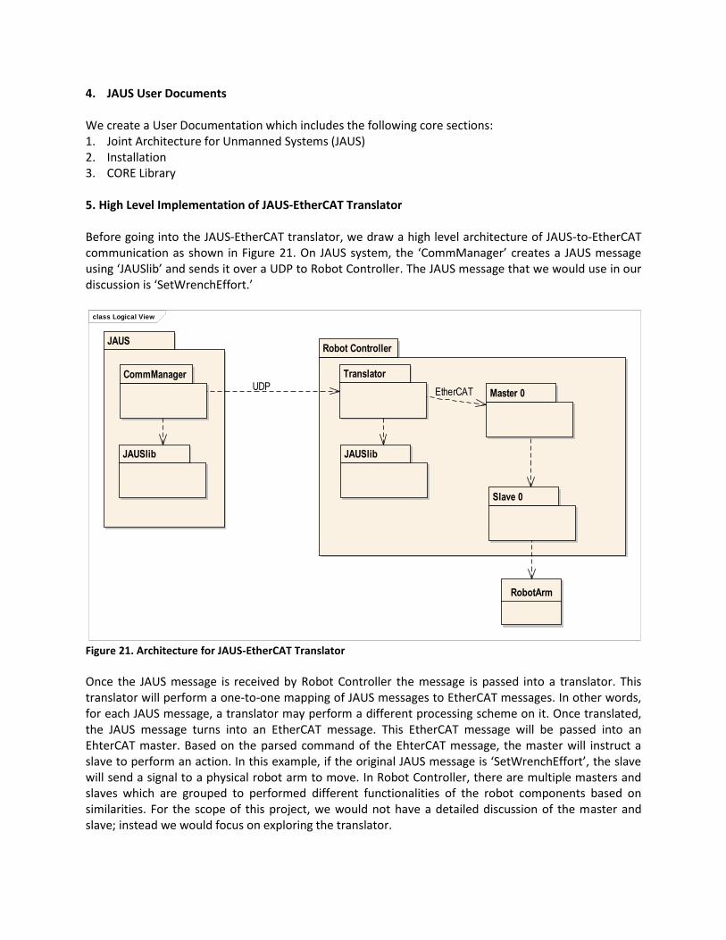
4. JAUS User Documents We create a User Documentation which includes the following core sections: 1. Joint Architecture for Unmanned Systems (JAUS) 2. Installation 3. CORE Library 5. High Level Implementation of JAUS-EtherCAT Translator Before going into the JAUS-EtherCAT translator, we draw a high level architecture of JAUS-to-EtherCAT communication as shown in Figure 21. On JAUS system, the ‘CommManager’ creates a JAUS message using ‘JAUSlib’ and sends it over a UDP to Robot Controller. The JAUS message that we would use in our discussion is ‘SetWrenchEffort.’
Figure 21. Architecture for JAUS-EtherCAT Translator
Once the JAUS message is received by Robot Controller the message is passed into a translator. This translator will perform a one-to-one mapping of JAUS messages to EtherCAT messages. In other words, for each JAUS message, a translator may perform a different processing scheme on it. Once translated, the JAUS message turns into an EtherCAT message. This EtherCAT message will be passed into an EhterCAT master. Based on the parsed command of the EhterCAT message, the master will instruct a slave to perform an action. In this example, if the original JAUS message is ‘SetWrenchEffort’, the slave will send a signal to a physical robot arm to move. In Robot Controller, there are multiple masters and slaves which are grouped to performed different functionalities of the robot components based on similarities. For the scope of this project, we would not have a detailed discussion of the master and slave; instead we would focus on exploring the translator.
class Logical View
JAUS
CommManager
Robot Controller
JAUSlib
Translator
JAUSlib
Master 0
Slave 0
RobotArm
UDPEtherCAT

As mentioned earlier, we will show how our translator can translate a ‘SetWrenchEffort’ message into an EtherCAT message. ‘SetWrenchEffort’ message controls platform mobility actuators by mapping the twelve command elements to the specific mobility controls of a vehicle [3]. ‘SetWrenchEffort’ message body is shown in Figure 22. For example, a typical wheeled vehicle can be controlled with only three elements of the wrench command: Propulsive Linear Effort X (throttle), Propulsive Rotational Effort Z (steering), and Resistive Linear Effort X (brake). For the scope of this project, we will show a proof of concept that a mapping from a JAUS message to an EtherCAT message can be done. For an EtherCAT message, we choose ETHERCAT_MASTER_PACKET_SDO_DOWNLOAD_REQ_T message. Our approach to build a translator is to compare both which fields from both JAUS and EtherCAT are relevant to each other. This means that the field matching are not limited to header-to-header or body-to-body, however it can be performed from header-to-body (and vice versa) as well. JAUS message header and body are shown in Figure 22 and Figure 23, while EtherCAT message header and body are shown in Figure 24 and Figure 25.
Figure 22. JAUS Message Header of ‘SetWrenchEffort’

Figure 23. JAUS Message Body of ‘SetWrenchEffort’

Figure 24. EtherCAT Message Header of ETHERCAT_MASTER_PACKET_SDO_DOWNLOAD_REQ_T
Figure 25. EtherCAT Message Body of ETHERCAT_MASTER_PACKET_SDO_DOWNLOAD_REQ_T
Based on this information, we see that some fields are possible to map while others are not. For all possible mappings, we create a table in Figure 26 below.
Figure 26. JAUS-to-EtherCAT Possible Field Mapping
Mapping number 1 is straight forward because JAUS subsystem matches with EtherCAT subsystem in header. Mapping number 2 to 4 are done by cross-mapping: from header to body because EtherCAT

header provides spaces to hold node-component routing in message body. Mapping number 2 is very clear because the naming convention for Node is the same. Mapping number 3 is not very clear at the first time we see it because the naming convention is different. Using EtherCAT requires creating objects. Before we define what an object is, we observe the message body of ECAT_OD_CREATE_OBJECT_REQ_T, as shown in Figure 27 below.
Figure 27. EtherCAT message body of ECAT_OD_CREATE_OBJECT_REQ_T
An object has an index and a number of sub-objects. We know that within a node, there could be multiple components. We can conclude it is acceptable to treat EtherCAT objects as JAUS component. As a result, mapping 3 is valid. Now, we need to proof that mapping 4 is also valid. We know that a component is the second lowest level in JAUS hierarchical structure. In other words, a component is the closest station to the physical devices. Thus, we need to treat an EtherCAT ulSubIndex (Object Sub Index) as a JAUS Command Code. JAUS command code is a set of instructions to be sent to specific unmanned vehicle’s physical devices. As a result, mapping 4 is also valid. For mapping number 3, we produce a mapping formula for JAUS-to-EtherCAT, which is ulIndex = 6900 (defined by Robot Controller) + ID (from Figure 28 below). For example, if the JAUS message is Global Pose Sensor in Platform Subgroup, our ulIndex would be 6900 + 38 = 6938.
Figure 28. Robot Controller-Defined JAUS Component ID correspondence to EtherCAT ulIndex

For mapping number 4, we simply list all the JAUS messages in order of Command Code, as shown in Figure 29, and transform it into an ascending number for EtherCAT ulSubIndex.
Figure 29. JAUS Command Code correspondence to EtherCAT ulSubIndex
We are now left with mapping the rest of fields that have not already been mapped. These JAUS header fields are shown in Figure 30, and are indicated by status ‘Unmapped’.
Figure 30. JAUS Header Fields that have not been Mapped
In addition to these unmapped header fields, all fields JAUS message body in Figure 8 are still unmapped as well. All these fields are still unmapped because they are not relevant to EtherCAT message structure. Therefore, our approach is to append all these fields into the EtherCAT field called ‘abSdoData’ (please refer to Figure 25). As a result, ‘abSdoData’ contains the following Bytes information shown in Figure 31.

Figure 31. Append JAUS Unmapped Fields into EtherCAT abSdoData Field
In order to keep track of abSdoData packet lengths (in bytes), we utilize EtherCAT ‘ulLen’ field (please refer to Figure 24). The formula is 16 + n, where 16 is the number of EtherCAT header fields, and n is the total number of bytes in EtherCAT packet (n = 28 for ‘SetWrenchEffort’ command). This concludes our high level architecture of our JAUS-EtherCAT translator. 6. Evaluation and Contribution JAUS users are interested in code, libraries, and APIs which allow them to integrate easily into existing systems and add JAUS functionality. What they expected cannot be satisfied because some of JAUS implementations do not provide their needs. In addition, some of JAUS implementations do not follow JAUS structure defined in Reference Architecture, and in fact the implementations are not complete. Our JAUS implementation solves all these problems because it strictly follows JAUS specifications and provides a library and an API. In addition, our JAUS implementation provides a 4+1 View Model for JAUS users to easily grasp the concept of our JAUS implementation and inject it into their existing unmanned systems. JAUS solves the interoperability issue for old unmanned systems communication, but JAUS suffers from a performance (latency) issue. Our approach is to use EtherCAT to solve the performance issue. In order to integrate JAUS with EtherCAT, we build a translator so that JAUS messages and EtherCAT messages can be translated into one another. EtherCAT might have been used for any other communication purposes, but it has not been used for JAUS. Thus, our idea of building a high level implementation of JAUS-EtherCAT is considered novel. 7. Conclusion and Future Work Software Architecture driven JAUS implementation provides an ease-of-use of JAUS implementation to robotics practitioners. Our JAUS model shows a high level view of how practitioners can inject our JAUS implementation into their existing unmanned systems, and this model is absent in any other JAUS

implementation. In addition, our JAUS implementation focuses only on the core of JAUS so that robotics practitioner can easily incorporate it into their existing unmanned systems. Our translator has been proven to be able to translate a JAUS message ‘SetWrenchEffort’ into an EtherCAT message ‘ETHERCAT_MASTER_PACKET_SDO_DOWNLOAD_REQ_T.’ The translator is built by mapping relevant fields from JAUS to EtherCAT and appending unmapped fields into EhterCAT SDO data field. This mapping is considered a one-to-one mapping. In other words, for different messages, the mapping structure would vary. One obvious future work would be a full implementation of this JAUS-EtherCAT translator. Our translator is not efficient since the mapping is a one-to-one mapping. The efficiency can also be improved by using a different algorithm or methodology. In addition, the performance of the translator has not yet been tested. All these items can be potential work in the future. References [1] H. M. Huang, E. Messina, and A. Jacoff. Performance Measures Framework for Unmanned Systems
(PerMFUS). Proceedings of the 9th Workshop on Performance Metrics for Intelligent Systems. September 21-23, 2009, Gaithersburg, MD, USA.
[2] M. Sugiura, K. Kobayashi, K. Watanabe, and T. Ohkubo. Development of Unmanned Ground Vehicle for IGVC JAUS Challenge. SICE Annual Conference 2008 August 20-22, 2008.
[3] JAUS Documents. The Joint Architecture for Unmanned Systems. http://www.openjaus.com/support/jaus-documents/. Last accessed on 18 April, 2011.
[4] P. B. Kruchten. The 4+1 View Model of Architecture. IEEE Software, 12 (6), 1995, pp. 42 – 50. [5] OpenJAUS Development Group Charter. http://www.openjaus.com/. Last accessed on 18 April, 2011. [6] OpenJAUS 4.0 vs. JAUS Toolset. http://www.openjaus.com/news/1-latest-news/96-editorial-
openjaus-40-vs-jaus-toolset/. Last accessed on 18 April, 2011. [7] Active-IST. http://active-ist.sourceforge.net/. Last accessed on 18 April, 2011. [8] Robotics Engineering Excellence. http://www.resquared.com/JAUS-SDK-Features-Benefits.html. Last
accessed on April 18, 2011. [9] H. Eichelberger. Automatic Layout of UML. Use Case Diagrams. Proceedings of the 4th ACM
Symposium on Software Visualization (SoftVis ‘08), September 16–17, 2008, Herrsching am Ammersee, Germany.
[10] UML 2.0 Infrastructure Specfication. Object Management Group. www.omg.org. Last accessed Jan. 3, 2010.
[11] A. Rounte, O. Volgin, and M. Reddoch. Static Control-Flow Analysis for Reverse Engineering of UML Sequence Diagram. Proceedings of the 6th ACM SIGPLAN-SIGSOFT workshop on Program Analysis for Software Tools and Engineering (PASTE ‘05), Lisbon, Portugal.
[12] S. Emadi and F. Shams. From UML Component Diagram to an Executable Model Based on Petri Nets. International Symposium on Information Technology (ITSim ‘08), Kuala Lumpur, Malaysia, 2008, pp. 1-8.
[13] J. Morrah. An Evaluation of the Performance of the Joint Architecture for Unmanned Systems in Comparison to Controller Area Network.
[14] EtherCAT Technology Group. http://www.ethercat.org/pdf/english/EtherCAT_Introduction_0905.pdf. Last accessed on 17 May, 2011.

[15] S. G. Robertz, R. Henriksson, K. Nilsson, A. Blomdell, and I.Tarasov. Using Real-time Java for Industrial Robot Control. Proceedings of the 5th international workshop on Java technologies for real-time and embedded systems (JTRES’07). September 26–28, 2007, Vienna, Austria.
[16] The German Aerospace Center (DLR). EtherCAT as a uniform communication platform for mobile service robots of the future: “Rollin’ Justin” robot drags crates and serves tea. http://ethercat.org/pdf/english/pcc_0210_dlr_e.pdf. Last accessed on 02/24/2011.
[17] PC Control: Continuous EtherCAT at all levels - EtherCAT for factory networking. http://ethercat.org/pdf/english/pcc_0409_etg_e.pdf. Last accessed on 02/24/2011.