titan turnaround integration in trajectory a network · analysis of the turnaround process ......
TRANSCRIPT

Project co-funded by the European Commission and TITAN consortium.
TITAN Turnaround Integration in Trajectory And Network
Project Number: 233690
Analysis of the current situation
CLASSIFICATION: PU ISSUE: 1.0 DATE: 24/05/2010
DOCUMENT REFERENCE
Project Work Package Partner Nature Number
TITAN WP1 SLO DEL 01

Analysis of the current situation Issue: v1.0
Date: 24/05/2010
TITAN: Turnaround Integration in Trajectory And Network Page 2 of 82
DOCUMENT CHANGE LOG
Issue Date Author Affected Sections / Comments
0.1 15/12/2010 Roland Guraly/ Noemi Kral Creation
0.2 15/01/2010-19/04/2010 WP1.1 partners Review of TITAN partners
0.3 19/04/2010 Roland Guraly Final document
1.0 24/05/2010 Roland Guraly/ Noemi Kral Review of EC
DOCUMENT CONTROL
Responsible Organisation Name Date
Author SLO Roland Guraly/ Noemi Kral 31/03/2010
Partners involved WP1.1 partners
Reviewer INE Laura Serrano Martin 31/03/2010
Approver INE Alvaro Urech 20/04/2010

Analysis of the current situation Issue: v1.0
Date: 24/05/2010
TITAN: Turnaround Integration in Trajectory And Network Page 3 of 82
DOCUMENT DISTRIBUTION
To/Cc Organisation Name
To European Commission Stephanie Stoltz-Douchet
To INECO Álvaro Urech
To INECO Laura Serrano
To INECO Ana C. Sáez
To INECO Sara Luis
To Aena Amalia García
To Jeppesen Alicia Grech
To CRIDA Nicolás Suarez
To CRIDA Susana Bravo
To CRIDA Eva Puntero
To ECORYS Robert Piers
To ECORYS Jolanta Rekiel
To Isdefe Vicente Bordón
To Isdefe Martijn Koolloos
To Isdefe Leticia Biescas
To Blusky Services Steve Zerkowitz
To BR & TE Javier García
To Slot Consulting Roland Gurály
To Slot Consulting Noémi Král
To RWTH AAchen University Sebastian Kellner
Cc SESAR JU Paul Adamson
Analysis of the current situation Issue: v1.0
Date: 24/05/2010
TITAN: Turnaround Integration in Trajectory And Network Page 4 of 82
Cc AENA/SESAR JU Alejandro Egido
Cc AENA/SESAR JU Francisco Javier Fernández de Liger

Analysis of the current situation Issue: v1.0
Date: 24/05/2010
TITAN: Turnaround Integration in Trajectory And Network Page 5 of 82
TABLE OF CONTENTS Executive summary ................................................................................................. 101. Introduction ........................................................................................................ 11
1.1 PURPOSE OF THE DOCUMENT ............................................................................. 11
1.2 INTENDED AUDIENCE / CLASSIFICATION ........................................................... 11
1.3 METHODOLOGY ..................................................................................................... 11
1.4 ASSOCIATED DOCUMENTATION .......................................................................... 11
1.5 ABBREVIATIONS AND ACRONYMS ...................................................................... 13
2. Analysis of the Turnaround process ................................................................ 172.1 SHORT DESCRIPTION OF THE PROCESS ............................................................ 17
2.2 ORGANIS ATIONS INVOLVED ................................................................................. 18
2.3 PROCESSES DURING THE TURNAROUND .......................................................... 20
2.3.1 The landside ................................................................................................... 202.3.1.1 Description of the processes ................................................................. 20
2.3.2 The Airside ..................................................................................................... 222.3.2.1 Summary of the processes ................................................................... 23
2.3.2.2 Detailed description of the processes ................................................... 25
2.3.2.3 Flow of the processes ........................................................................... 26
2.4 MILESTONES .......................................................................................................... 28
2.5 ANALYSIS OF BOTTLENECKS .............................................................................. 30
2.5.1 Real causes of delays .................................................................................... 302.5.2 Shortcomings ................................................................................................. 32
2.6 ANALYSIS OF TIMES .............................................................................................. 33
2.6.1 Buffer time concept ........................................................................................ 332.6.2 Buffer time estimation ................................................................................... 352.6.3 Buffer time and milestones ........................................................................... 39
3. Conflicts in the Turnaround .............................................................................. 413.1 INTERNAL CONFLICTS .......................................................................................... 42
3.1.1 Reckless Driving ............................................................................................ 433.1.1.1 Crossing forbidden areas ...................................................................... 43
3.1.1.2 Reckless Driving on Platform ................................................................ 44
3.1.1.3 Parked or stopped vehicle in a forbidden area ...................................... 44
3.1.2 Training ........................................................................................................... 45

Analysis of the current situation Issue: v1.0
Date: 24/05/2010
TITAN: Turnaround Integration in Trajectory And Network Page 6 of 82
3.1.2.1 Damage to the Aircraft .......................................................................... 45
3.1.2.2 Lack of synchronization ........................................................................ 45
3.1.3 Poor Maintenance .......................................................................................... 463.1.3.1 Fuel on the apron ................................................................................ 46
3.1.3.2 Remote aprons ..................................................................................... 46
3.1.4 Passenger ....................................................................................................... 463.1.4.1 Missing Passenger ............................................................................... 46
3.1.4.2 Special Passenger Procedures ............................................................. 47
3.1.5 Baggage .......................................................................................................... 473.1.5.1 Lost Baggage ....................................................................................... 47
3.1.5.2 Dropped Baggage ................................................................................ 48
3.1.6 Winter Procedures ......................................................................................... 483.1.6.1 Poor conditioning of the facilities ........................................................... 48
3.1.6.2 Environmental Control System ............................................................. 49
3.2 BOUNDARY CONFLICTS ........................................................................................ 49
3.2.1 Wet pavement ................................................................................................. 503.2.2 Iced Aircraft .................................................................................................... 503.2.3 Unknown Position .......................................................................................... 533.2.4 Sick Passenger ............................................................................................... 543.2.5 Engine Failure ................................................................................................ 563.2.6 Ground Contact-off Runway .......................................................................... 58
4. Information sharing ............................................................................................ 594.1 INFORMATION TRANSFER .................................................................................... 59
4.1.1 Actors ............................................................................................................. 594.1.2 Information transfer between partners ......................................................... 59
4.2 INFORMATION MANAGEMENT .............................................................................. 61
4.2.1 Airport Information Systems ......................................................................... 61Airport Trans-sectoral Systems ........................................................................ 63
4.2.1.1 Systems Operated at the Terminal ....................................................... 63
4.2.1.2 Systems Operated at the Baggage Handling System ........................... 64
4.2.1.3 Systems Operated at the Apron ............................................................ 65
4.2.1.4 Messages passing and routing in an Airport Environment .................... 66
4.2.1.5 Summary of systems and their usage in the airport environment .......... 67
4.2.2 Airline Information Systems .......................................................................... 68
Analysis of the current situation Issue: v1.0
Date: 24/05/2010
TITAN: Turnaround Integration in Trajectory And Network Page 7 of 82
4.2.2.1 Information Systems for Communication with Customers and Increasing business ............................................................................................... 68
4.2.2.2 Information Systems for Planning and Process Optimisation ................ 68
5. Identification of potential improvements ......................................................... 705.1 IDENTIFY CURRENT LEVEL OF MATURITY .......................................................... 70
5.1.1 Research on turnaround processes ............................................................. 705.1.1.1 Scheduling and rescheduling ................................................................ 70
5.1.1.2 Disruption Management ........................................................................ 70
5.1.1.3 Turnaround time modelling ................................................................... 71
5.1.2 Industry improvements regarding turnaround times .................................. 715.1.2.1 Turnaround time improvements ............................................................ 71
5.1.2.2 Financial incentives related to turnaround times ................................... 72
5.1.3 New developments ......................................................................................... 725.1.3.1 Material Management ........................................................................... 72
5.1.3.2 Radio-Frequency Identification ............................................................. 73
5.1.4 Summary of the improvements ..................................................................... 735.1.4.1 Efficiency of LCCs ................................................................................ 73
5.1.4.2 Operations ............................................................................................ 73
5.1.4.3 Information and communication ............................................................ 74
5.2 BEST PRACTICES IN EUROPE AND US A. BENEFITS EXPERIENCED IN EUROPEAN CDM PROJ ECTS ......................................................................................... 74
5.2.1 Historical perspective .................................................................................... 745.2.2 CDM applications in the USA and Europe .................................................... 755.2.3 CDM application benefits .............................................................................. 765.2.4 The scope of CDM .......................................................................................... 775.2.5 CDM and the European community specifications ...................................... 785.2.6 CDM at European airports ............................................................................. 79
6. Conclusions ........................................................................................................ 817. ANNEX 1 .............................................................................................................. 82
Analysis of the current situation Issue: v1.0
Date: 24/05/2010
TITAN: Turnaround Integration in Trajectory And Network Page 8 of 82
LIST OF FIGURES Figure 1: Aircraft servicing arrangement ...............................................................................19
Figure 2: Check-in process ...................................................................................................21
Figure 3: Turnaround process ..............................................................................................27
Figure 4: Turnaround activities and milestones .....................................................................28
Figure 5: En-route and Airport Delays ..................................................................................30
Figure 6: Sample of aircrafts .................................................................................................35
Figure 7: Buffer time estimation ............................................................................................37
Figure 8: Buffer time histogram ............................................................................................38
Figure 9: Post-processed buffer time histogram ...................................................................39
Figure 10: Boundary Conflicts ..............................................................................................42
Figure 11: Average Time ......................................................................................................42
Figure 12: Crossing forbidden areas .....................................................................................43
Figure 13: Reckless Driving on Platform ...............................................................................44
Figure 14: Vehicle standing outside EPA and ESA ...............................................................44
Figure 15: Iced Aircraft .........................................................................................................52
Figure 16: Unknown Position ................................................................................................53
Figure 17: Sick Passenger ...................................................................................................55
Figure 18: Engine Failure .....................................................................................................57
Figure 19: Ground contact-off Runway .................................................................................58
Figure 20: Information transfer .............................................................................................60
Figure 21: Overview of Airport Information Systems .............................................................62
Figure 22: Relationship between ERs, IRs and CSs .............................................................78
Figure 23: Wet pavement .....................................................................................................82

Analysis of the current situation Issue: v1.0
Date: 24/05/2010
TITAN: Turnaround Integration in Trajectory And Network Page 9 of 82
LIST OF TABLES Table 1: Acronyms and definitions ........................................................................................16
Table 2: Activities identified in turnaround ............................................................................23
Table 3: List of Milestones ....................................................................................................29
Table 4: Stakeholders’ concerns ..........................................................................................32
Table 5 Turnaround activities. ..............................................................................................41
Table 6: Crossing forbidden areas ........................................................................................43
Table 7: Reckless Driving on Platform ..................................................................................44
Table 8: Park outside the EPA or stay out of the ESA ..........................................................45
Table 9: Damage to the aircraft ............................................................................................45
Table 10: Lack of synchronization ........................................................................................45
Table 11: Split fuel on the apron ...........................................................................................46
Table 12: Conflicts on remote aprons ...................................................................................46
Table 13: Late or missed passenger .....................................................................................47
Table 14: Special passenger procedures ..............................................................................47
Table 15: Lost baggage ........................................................................................................47
Table 16: Dropped baggage .................................................................................................48
Table 17: Poor maintenance of the facilities .........................................................................48
Table 18: Environmental Control System ..............................................................................49
Table 19: Process code ........................................................................................................49
Table 20: Colour code ..........................................................................................................50
Table 21: Actors and their responsibility ...............................................................................59
Table 22: Systems operated at several areas .......................................................................63
Table 23: Systems operated at the terminal area .................................................................64
Table 24: Systems operated at the baggage handling system ..............................................64
Table 25: Systems operated at the apron area .....................................................................66

Analysis of the current situation Issue: v1.0
Date: 24/05/2010
TITAN: Turnaround Integration in Trajectory And Network Page 10 of 82
EXECUTIVE SUMMARY The Turnaround Integration in Trajectory and Network (TITAN) project directly addresses the airport operations focusing on the turnaround process. The consortium will develop a new advanced operational concept for the turnaround process fully compatible and complementary with the ConOps developed within SESAR as well as a specific tool for the Airlines to benefit from the concept.
WP1 identifies the problems, user needs and expectations, set the performance target objectives and propose an operational concept fully in line with ICAO and SESAR concept of operations.
The “Analysis of the current situation” document is the first deliverable of WP1. This document describes the current turnaround process, the stakeholders involved, the bottlenecks, the analysis of buffer times, the possible conflicts that may appear in the daily operation, the information sharing between partners and the potential improvements.

Analysis of the current situation Issue: v1.0
Date: 24/05/2010
TITAN: Turnaround Integration in Trajectory And Network Page 11 of 82
1. INTRODUCTION
1.1 Purpose of the document The TITAN project (Turnaround Integration in Trajectory and Network) is aimed at enhancing the predictability, cost efficiency and punctuality of the operations by improving their turnaround process.
The objective of this document is to introduce the current turnaround process and reveal the problems that the stakeholders are facing during it.
1.2 Intended audience / Classification This document is a public project deliverable and is prepared for all the European aviation community.
1.3 Methodology Based on the level of expertise of consortium members task allocation has been performed. Making use of their own experience supported by internet literature the members gave a thorough description and analysis of the turnaround process and identified possible conflicts that might occur during turnaround, information sharing and information transfer. These results has been compiled and harmonised by the WP leader and reviewed initially by the project coordinator and later by all the work package participants who has a complementary expertise in the field of CDM and the turnaround process.
Finally the main findings of the document were presented during the 1st TITAN Workshop in Brussels on the 17th of March 2010 and were validated by the group of external attendees.
The different sources of the literature research discussed above are listed in Chapter 1.4
1.4 Associated documentation 1. Adeleye, Sanya, Chung, Christopher, a simulation based approach for contingency
planning for aircraft turnaround operation system activities in airline hubs, Journal of Air Transportation, 2006
2. Airport CDM – Steps to boost efficiency
3. Airport Handling Manual. 27th Edition.
4. Andersson, K., Carr, F., Feron, E., and Hall, W. (2000). Analysis and modelling of ground operations at hub airports. 3rd USA/Europe Mr Traffic Management R&D Seminar. 1-15.
5. ASSET - Assessment of stakeholders’ bottlenecks and issues
6. Barnett Troy, Improving Ramp / Terminal Operations for Shorter Turn-Times, Maintenance and Ground Operations Systems, BOEING 2008,
7. BOEING, Airplane characteristic for airport planning, 2005
8. Braaksma, J. P., and Shortreed, J. H. (1971). Improving airport gate usage with critical path. Journal of Transportation Engineering, 97(2), 187-203.
Analysis of the current situation Issue: v1.0
Date: 24/05/2010
TITAN: Turnaround Integration in Trajectory And Network Page 12 of 82
9. Cheng, Yu (1998). Network-based simulation of aircraft at gates in airport terminals. Journal of Transportation Engineering, 124(2). 188-196.
10. Cheng-Lung Wu, Robert E. Caves, Modelling of aircraft rotation in a multiple airport environment, Transportation Research part E 38, 265-277, 2002
11. DFS Deutsche Flugsicherung GmbH, Airport CDm Munich Results 2008, v1.0
12. E-OCVM, EUROCONTROL, v3.0
13. EP3 Collaborative Airport Planning, M1, v2.0, 01/02/2010
14. ETSI, Airport Collaborative Decision Making (A-CDM); Community Specification for application under the Single European Sky Interoperability Regulation EC 552/2004, v1.1.1
15. EUROCONTROL – CFMU, Network Operation Report. Summer 2008.
16. EUROCONTROL, ATM Airport Performance (ATMAP) Framework Measuring Airport Airside and Nearby Airspace Performance, Dec. 2009
17. EUROCONTROL, Digest - Annual 2008. Delays to air transport in Europe
18. EUROCONTROL, Proposed Refinement for the Deployment Criteria for Airports & Aerodrome ATC Linked to SESAR IP1 / Implementation Status Table / Basis for Airport Stakeholders Action Plan, Working Paper 01
19. EUROCONTROL: Performance Review Report. May 2009
20. EUROCONTROL; Airport CDM Applications Guide
21. Gordon Comstock, Speed up embarkation on low-cost flights, Mar 08 2006
22. Gu, Y., and Chung, C. (1999). Genetic algorithm approach to aircraft gate reassignment problem. Journal of Transportation Engineering, 725(5), 384-389.
23. Gupta, P., Bazargan, M., and McGrath, R. (2003). Simulation model for aircraft line maintenance planning. Proceedings of the 2003 IEEE Annual Reliability and Maintain Ability Symposium. 387-391.
24. Herroelen Willy, Leus Roel, Project scheduling under uncertainty: Survey and research potentials, European Journal of Operational Research 165 (2005) 289–306
25. http://cdm.fly.faa.gov
26. http://www.airbus.com
27. http://www.domain-b.com
28. http://www.halfbakery.com
29. IATA, INFLIGHT CATERING , Process Analysis and User Requirements, 2007
30. IATA, RFID IN AVIATION, 2008,
31. Impact Study of Landside Elements on Airport Capacity and Delays, EUROCONTROL, v1.0, November 2009
32. Jeppesen GmbH, Airport Optimization Analysis, 2007
33. Kuster Jurgen, Jannach Dietmar, Friedrich Gerhard, Extending the RCPSP for modelling and solving disruption management problems, Applied Intelligence (2009) 31: 234-253, 2008,

Analysis of the current situation Issue: v1.0
Date: 24/05/2010
TITAN: Turnaround Integration in Trajectory And Network Page 13 of 82
34. Landeghem, H., and Beuselinck, A. (2002). Reducing passenger boarding time in airplane: A simulation based approach. European Journal of Operational Research, 142(2), 294-308.
35. Mariano Domingo Calvo, 2005, Aena. Descubrir el handling aeroportuario
36. Mirza Mansoor, Economic Impact of Airplane Turn-Times, Economic and Financial Analysis Group, BOEING 2008
37. Ottman, W., Ford, A., and Reinhardt, G. (1999). An aircraft taxi simulation model for the United Parcel Service Louisville Air Park. Proceedings of the 1999 Winter Simulation Conference. 1221-1225.
38. SESAR Definition Phase D1
39. Teodorovic, D., and Stojkovic, G. (1995). Model to reduce airline schedule disturbances. Journal of Transportation Engineering, 121(4), 324-331.
40. Thorne Alan, Barrett Dan, McFlane Duncan, Impact of RFID on Aircraft Turnaround Process, Auto-ID Lab, University of Cambridge, UK, 2007
41. TITAN Description of work, Annex I v0.4
42. Van de Vonder Stijn, Demeulemeester Erik, Herroelen Willy, A classification of predictive-reactive project scheduling procedures, J Sched (2007) 10: 195–207
1.5 Abbreviations and Acronyms Abbreviation Meaning Definition
a/c Aircraft
ACARS Aircraft Communications Addressing and Reporting Systems
AFP Airspace Flow Program
AFS Aeronautical Fixed Service
AFTN Aeronautical Fixed Telecommunications Network
AIBT Actual In-Block Time
The time that an aircraft arrives in blocks. (Equivalent to Airline/Handler ATA –Actual Time of Arrival, ACARS = IN).
AMHS ATS Message Handling System
ANSP Air Navigation Service Provider
Aircraft Operator
A person, organization or enterprise engaged in or offering to engage in an aircraft operation. (ICAO Doc 4444, Chapter 1)
AOBT Actual Off-Block Time
Time the aircraft pushes back / vacates the parking position. (Equivalent to Airline / Handlers ATD – Actual Time of Departure & ACARS=OUT)

Analysis of the current situation Issue: v1.0
Date: 24/05/2010
TITAN: Turnaround Integration in Trajectory And Network Page 14 of 82
Abbreviation Meaning Definition
AOC Airport Operations Control
APU Auxiliary Power Unit
A-SMGCS Advanced Surface Movement Guidance and Control System
ATC Air Traffic Controller
ATFM Air Traffic Flow Management
ATOT Actual Take-Off Time
The time that an aircraft takes off from the runway. (Equivalent to ATC ATD–Actual Time of Departure, ACARS = OFF).
ATS Air Traffic Services
CBA Cost Benefit Analysis
CbTA Control by Time of Arrival
CDM Collaborative Decision Making An environment in which the consequences of decisions taken are visible to all partners.
CFMU Central Flow Management Unit
Central Flow Management Unit (CFMU), Brussels – A Central Management Unit operated by EUROCONTROL. (ICAO Doc 7754, Volume I, Part V.III, paragraph 3)
CIDIN Common ICAO Data Interchange Network
CMS Contract Management System
CS Community Specification
CTOT Calculated Take-off Time
Calculated Take-Off Time (CTOT) – A time calculated and issued by the appropriate central management unit, as a result of tactical slot allocation, at which a flight is expected to become airborne. (ICAO Doc 7030/4 – EUR, Table 7)
DCV Destination Coded Vehicle
ECS Environmental Control System
EDA Emergency Distance Available
EPA Equipment Parking Area
ER Essential Requirements
ESA Equipments Standing Area
FAA Federal Aviation Administration

Analysis of the current situation Issue: v1.0
Date: 24/05/2010
TITAN: Turnaround Integration in Trajectory And Network Page 15 of 82
Abbreviation Meaning Definition
FADE FAA/Airline Data Exchange
FIDS Flight Information Display System
FPD Freezing Point Depressant
FSM Flight Schedule Monitor
GMC Ground Movement Controller
GPSS Ground Processing Scheduling System
ICR Integrated Collaborative Rerouting
IR Implementing Rule
LCC Low Cost Carrier
LCL Load Controller
LoA Letter of Agreement
MTOW Maximum Take-off Weight
NOTAM Notice to Airmen
OPIS Opportunistic Intelligent Scheduler
PAX Passengers
PIC Pilot In Command
PRR Performance Review Report
PSZ Public Safety Zone
RBT Reference Business Trajectory
RFID Radio-Frequency Identification
SC Schengen
SIBT Scheduled In-Block Time The time that an aircraft is scheduled to arrive at its parking position.
SLA Service Level Agreement
SMS Surface Management System
STA Scheduled Time of Arrival
SWIM System Wide Information Management
TIBT Target In Block Time
TITAN Turnaround Integration in Trajectory And Network
TOBT Target Off-Block Time The time that an aircraft operator / handling agent estimates that an aircraft will be ready, all doors closed,

Analysis of the current situation Issue: v1.0
Date: 24/05/2010
TITAN: Turnaround Integration in Trajectory And Network Page 16 of 82
Abbreviation Meaning Definition
boarding bridge removed, push back vehicle present, ready to start up / push back immediately upon reception of clearance from the TWR.
UDP Unified Ground Delay Program
WAN Wide Area Network Table 1: Acronyms and definitions

Analysis of the current situation Issue: v1.0
Date: 24/05/2010
TITAN: Turnaround Integration in Trajectory And Network Page 17 of 82
2. ANALYSIS OF THE TURNAROUND PROCESS The turnaround of an aircraft comprises the set of services required from the moment the aircraft arrives at its stand (AIBT – Actual In-Block Time) until the time it leaves it (AOBT – Actual Off-Block Time). Many organisations are involved in the turnaround making it a complex operation with a large potential for inefficiencies.
The turnaround time is also known as gate occupancy time as it directly affects the number of aircraft that can use a gate over the course of the day. On the other hand the turnaround time also affects the number of flights that can be performed by an aircraft per day.
Aircraft turnaround times range from twenty minutes to three hours for passenger carriers.
2.1 Short description of the process The turnaround process includes a set of operations that are performed in a sequential way and must be coordinated to optimize the process without causing damage to the target off-block time.
The turnaround time depends on:
• The size of aircraft: bigger aircraft require longer turnarounds. For example, the minimum turnaround time for a B747 is one and a half hour, while for a B737-800 operated by a low-cost carrier is 30 minutes. The absolute minimum turnaround time is limited by the time needed for the brakes to cool down. Currently this limit is 20 minutes;
• The itinerary of aircraft: Whether the flight is short-haul or long haul, since short-haul flights are operated with higher frequency than long haul, while long-haul flights require longer pre-flight servicing time;
• The number of passengers;
• The volume of cargo to be loaded and unloaded;
• Company operating strategy: some airlines plan a greater time buffer for turnarounds into their schedule to help manage the effects of delays.
Typical turnaround process:
1. Arrival of the aircraft to the stand;
2. Placing of chocks in front of the aircraft's wheels;
3. Ground Power Supply;
4. Unloading of passengers and baggage;
5. Post-flight administration: the preparation and the handover of the documents of the flight completed and of the internal mail for example;
6. Pre-flight administration: the check and the preparation of the documents for the next flight (for example: loadsheet, fuel figures, NOTAM, information on whether, etc.);
7. Aircraft refuelling;
8. Catering replenishment;

Analysis of the current situation Issue: v1.0
Date: 24/05/2010
TITAN: Turnaround Integration in Trajectory And Network Page 18 of 82
9. Aircraft cleaning;
10. Deflation of waste water;
11. Replenishment of potable water;
12. Security checks;
13. Loading of passengers and baggage;
14. De-icing of the aircraft: the process of removing frozen contaminant, snow, ice, slush, from the surface of the aircraft (wings, fuselage, etc.). It is usually executed by use of dry or liquid chemicals. It can happen at the stand of the aircraft or at a determined place of the airport;
15. Removal of chocks for departure;
16. The aircraft leaves the stand.
The turnaround process may vary according to the servicing arrangement and turnaround tasks for different types of aircraft and different operators.
From crew’s view turnaround process starts with marshalling. This activity comprises docking (the accurate positioning of an aircraft on its stand by the use of sensors) and other activities like removing blanking covers, landing gear locks, cockpit steps…
2.2 Organisations involved The main actors involved in the turnaround process are:
• Aircraft Operator;
• Ground Handlers;
• Air Navigation Services Provider (ANSP);
• Airport Operator;
• Central ATFM Unit (CFMU);
• Meteorological Centre.
The main support functions of the above organizations involved in the turnaround process are as follows:
• Stand management;
• A common data repository where all shared data is stored at the airport;
• An efficient CDM process at airline and airport levels;
• Airline fleet management and passenger handling.
Another important factor to be considered, although it is not part of the turnaround process, is the gate usage agreement (this defines which gate the airline prefers to use) between the airline and the handling organisation or the Airport Operator. This factor may cause substantial differences in the type of services required.

Analysis of the current situation Issue: v1.0
Date: 24/05/2010
TITAN: Turnaround Integration in Trajectory And Network Page 19 of 82
The following ground services are required for the execution of the turnaround process:
1. Provision of electrical power;
2. Fuelling;
3. Removal of waste water;
4. Provision of potable water;
5. Provision of catering and cleaning;
6. Low pressure Air (air conditioning, cooling/heating);
7. High Pressure Air (engine start);
8. De-icing;
9. Pushback/towing;
10. Aircraft baggage/cargo/mail/ULD handling;
11. Provision of passenger boarding/de-boarding equipment;
12. Passenger configuration;
13. Aircraft baggage/cargo/mail/ULD quantity and configuration.
In order to improve the efficiency of the turnaround process, the handling services are always carried out in the same configuration in every airport. This is a fixed position schema, common to every aircraft and handling vehicle.
Figure 1: Aircraft servicing arrangement
Notes
1. If the auxiliary power unit (APU) is used, the electrical, air start and air-conditioning service vehicles are not required.
:
2. Passenger loading bridges or portable passenger stairs are used to load or unload passengers.
Analysis of the current situation Issue: v1.0
Date: 24/05/2010
TITAN: Turnaround Integration in Trajectory And Network Page 20 of 82
2.3 Processes during the turnaround
2.3.1 The landside A traditional, though sometimes arbitrary, division of an airport creates an “airside” and a “landside”. The practical line of division may be at the boarding gate (as in the Total Airport Management concept) or at the security screening area or some other place selected on the basis of local requirements. Although the division line itself may be at different places at different airports, the rules and responsibilities on both sides of the dividing line show many similarities and the same is true for the access rights management applied to the airside. The landside includes gates, terminals, cargo storage areas, parkings and ground access.
The airport facilitation (processes within the building) is under the jurisdiction of the airport authorities and becomes dependent upon any letters of agreement (LoA) or service level agreements (SLA) between the airline, the ground handling companies and the airport operator.
2.3.1.1 Description of the processes
The landside processes formally don’t constitute a part of the turnaround, but they have a direct effect on it:
1. Connection to the city: The airports are connected to the city by public roads and often rail tracks. A traffic jam or an accident on the road or rail track leading to the airport obviously causes late arrival of a passenger to the check-in gate.
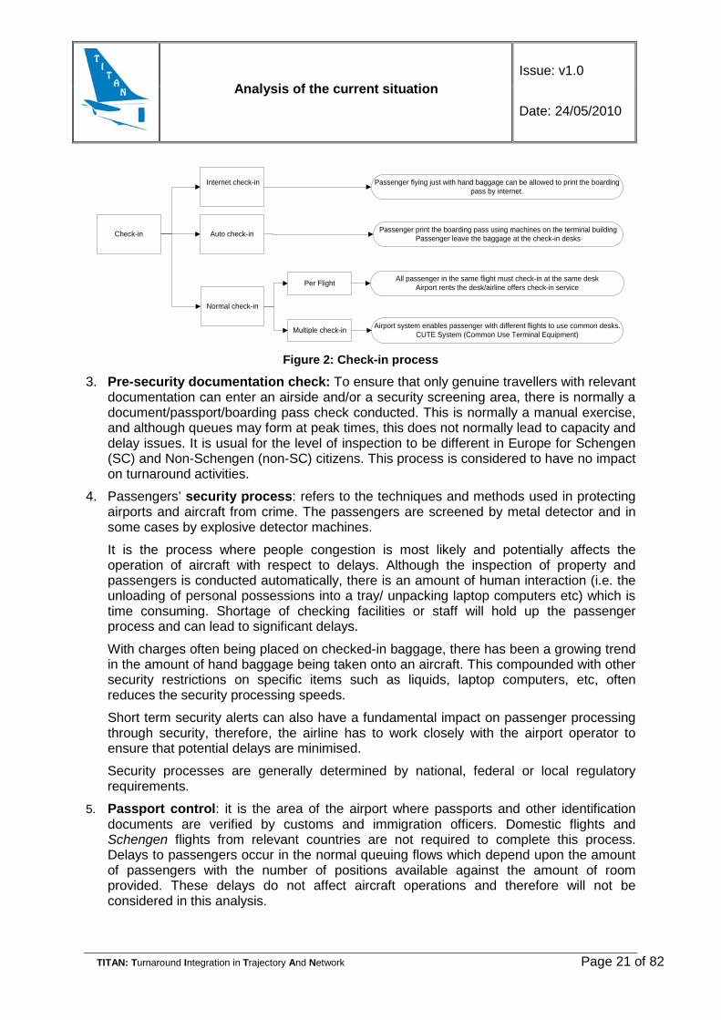
2. Check-in (bag drop-off and self check in): This process begins when a passenger enters a queue to obtain a boarding pass and/or delivers baggage to the airline staff and ends when the passenger leaves the desk for the next facility. This process is normally handled by an airline or a handling agent working on behalf of an airline.
The capacity of this facility is determined by the passenger processing time, the number of counters, opened and available staff. Processing time can vary according to a number of factors such as staff experience, destination market, and passenger characteristics. Capacity of check-in process facilities is judged by the average service time and the number of passengers in a holding area against the level of service in the design of the facility.
To reduce the possibility of delays at this process, airlines and airports have introduced other systems, such as self-check in and baggage drop off facilities. These have proven successful in reducing congestion at these facilities and therefore the chances of a delay associated.
Analysis of the current situation Issue: v1.0
Date: 24/05/2010
TITAN: Turnaround Integration in Trajectory And Network Page 21 of 82
Per Flight
Multiple check-in
Passenger flying just with hand baggage can be allowed to print the boarding pass by internet.
Passenger print the boarding pass using machines on the terminal buildingPassenger leave the baggage at the check-in desks
All passenger in the same flight must check-in at the same deskAirport rents the desk/airline offers check-in service
Airport system enables passenger with different flights to use common desks. CUTE System (Common Use Terminal Equipment)
Check-in
Internet check-in
Auto check-in
Normal check-in
Figure 2: Check-in process
3. Pre-security documentation check: To ensure that only genuine travellers with relevant documentation can enter an airside and/or a security screening area, there is normally a document/passport/boarding pass check conducted. This is normally a manual exercise, and although queues may form at peak times, this does not normally lead to capacity and delay issues. It is usual for the level of inspection to be different in Europe for Schengen (SC) and Non-Schengen (non-SC) citizens. This process is considered to have no impact on turnaround activities.
4. Passengers’ security process: refers to the techniques and methods used in protecting airports and aircraft from crime. The passengers are screened by metal detector and in some cases by explosive detector machines.
It is the process where people congestion is most likely and potentially affects the operation of aircraft with respect to delays. Although the inspection of property and passengers is conducted automatically, there is an amount of human interaction (i.e. the unloading of personal possessions into a tray/ unpacking laptop computers etc) which is time consuming. Shortage of checking facilities or staff will hold up the passenger process and can lead to significant delays.
With charges often being placed on checked-in baggage, there has been a growing trend in the amount of hand baggage being taken onto an aircraft. This compounded with other security restrictions on specific items such as liquids, laptop computers, etc, often reduces the security processing speeds.
Short term security alerts can also have a fundamental impact on passenger processing through security, therefore, the airline has to work closely with the airport operator to ensure that potential delays are minimised.
Security processes are generally determined by national, federal or local regulatory requirements.
5. Passport control: it is the area of the airport where passports and other identification documents are verified by customs and immigration officers. Domestic flights and Schengen flights from relevant countries are not required to complete this process. Delays to passengers occur in the normal queuing flows which depend upon the amount of passengers with the number of positions available against the amount of room provided. These delays do not affect aircraft operations and therefore will not be considered in this analysis.

Analysis of the current situation Issue: v1.0
Date: 24/05/2010
TITAN: Turnaround Integration in Trajectory And Network Page 22 of 82
6. Baggage processes (inbound and outbound): The baggage process for an outbound flight begins when the passengers deliver their baggage at the check-in facility at which point it is transported, by various electronic and manual means, through a hold baggage search area, and delivered to an aircraft hold for that particular flight. A similar process takes place for arriving baggage, when from the aircraft; the luggage is transported to a baggage sortation area, before being delivered onto an arrival baggage carousel.
The baggage handling system is of major importance to an efficient airline and airport operation. For an efficient baggage handling system the baggage flow should be rapid and simple; not conflict with the flow of passengers, cargo, crew or vehicles; provide the facilities for oversized baggage; and have plans for fallback handling in the event of a failure of the system.
Service levels and customer satisfaction factors are the key measurement indicators (usually ‘first bag’ and ‘last bag’ to be delivered to the reclaim area from the arriving aircraft).
7. Stand management: The allocation of aircraft parking stands is a vital factor in the efficiency of the aircraft turnaround process. The key aspects of stand availability are the number of stands for different aircraft types and sizes; the availability of these stands as influenced by the occupancy times; and the flexibility of stands to handle different aircraft types and sizes throughout the day. This is a vital element and the one most likely to suffer from a lack of capacity and therefore delays. There should be an ongoing process to ensure that the parking stands available meet the size requirements of the aircraft using the airport. Early discussions about proposed airline fleet changes can minimise the potential impact of such changes.
The efficient allocation of aircraft parking positions is affected by various factors such as the airline schedule, the given infrastructure, proximity to transfer facilities, ground handler locations and the proficient handling of traffic on the ground. These factors have been traditionally considered as airside elements. However, the management of the allocated stand still resides within the landside element process. The use and availability of equipment and facilities are crucial to the operation of the aircraft. The use of the airbridges, where available, assists with the efficient movement of passengers to and from the aircraft ensuring an efficient turnaround and use of the allocated stand.
For the turnaround process, which includes the passenger and baggage processing and handling and the servicing of the aircraft, to be effective, some form of supervision of the co-ordinated activities must take place. This co-ordination and timing of activities is usually established through Airport Collaborative Decision Making best practices. This process should be monitored for its effect on delays and reported according to the decision of the ground handler or aircrew, as appropriate, if a delay has occurred.
The landside elements which have the main impact on capacity and delays are the check-in, aircraft boarding and security processes.
2.3.2 The Airside The airside means the airport facilities associated with aircraft movement to transport passengers and cargo, used primarily for landing and take-off, for example runways, taxiways.
Analysis of the current situation Issue: v1.0
Date: 24/05/2010
TITAN: Turnaround Integration in Trajectory And Network Page 23 of 82
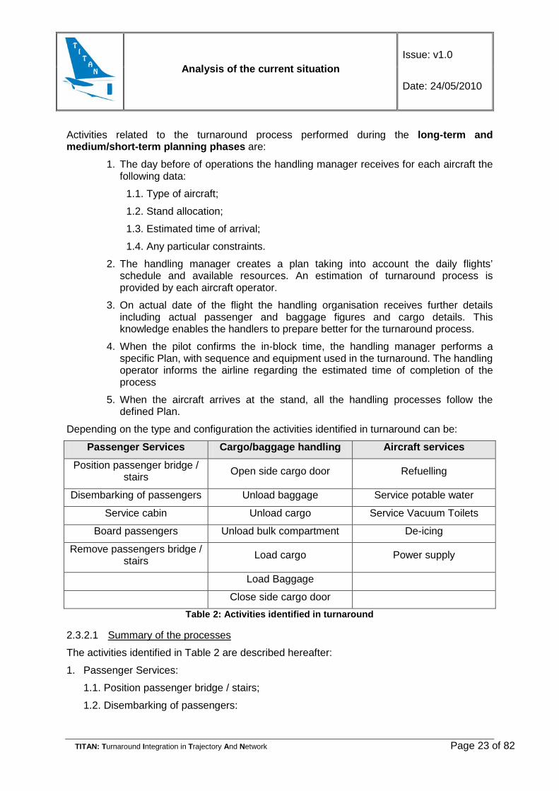
Activities related to the turnaround process performed during the long-term and medium/short-term planning phases are:
1. The day before of operations the handling manager receives for each aircraft the following data:
1.1. Type of aircraft;
1.2. Stand allocation;
1.3. Estimated time of arrival;
1.4. Any particular constraints.
2. The handling manager creates a plan taking into account the daily flights’ schedule and available resources. An estimation of turnaround process is provided by each aircraft operator.
3. On actual date of the flight the handling organisation receives further details including actual passenger and baggage figures and cargo details. This knowledge enables the handlers to prepare better for the turnaround process.
4. When the pilot confirms the in-block time, the handling manager performs a specific Plan, with sequence and equipment used in the turnaround. The handling operator informs the airline regarding the estimated time of completion of the process
5. When the aircraft arrives at the stand, all the handling processes follow the defined Plan.
Depending on the type and configuration the activities identified in turnaround can be:
Passenger Services Cargo/baggage handling Aircraft services
Position passenger bridge / stairs Open side cargo door Refuelling
Disembarking of passengers Unload baggage Service potable water
Service cabin Unload cargo Service Vacuum Toilets
Board passengers Unload bulk compartment De-icing
Remove passengers bridge / stairs Load cargo Power supply
Load Baggage
Close side cargo door Table 2: Activities identified in turnaround
2.3.2.1 Summary of the processes
The activities identified in Table 2 are described hereafter:
1. Passenger Services:
1.1. Position passenger bridge / stairs;
1.2. Disembarking of passengers:

Analysis of the current situation Issue: v1.0
Date: 24/05/2010
TITAN: Turnaround Integration in Trajectory And Network Page 24 of 82
1.2.1. Disembarking of passengers from the aircraft to the terminal can be done by the use of a “boarding bridge” or by bus using “boarding stairs”. Although the baggage reclaim operation is closely related to the actual flight it is not influencing the actual turnaround process as in worst case scenario it even might be performed after the aircraft leaves the airport.
1.2.2. The boarding bridge is used to connect directly to the boarding gate of an aircraft positioned close to the terminal building. Beside the fast offload and load of the passengers this configuration provides additional benefits like auxiliary power from the power-net or easier contact between the crew and the handling staff.
1.2.3. In case of a remote stand, boarding stairs and passenger coaches are used to facilitate the operations between the terminal building and the aircraft. Due to the fact that various vehicles are needed, their use affects the duration of services like cleaning, APU, provision of documents (meteorological information, flight plan, balance sheet), supply of electric power, fuelling, etc.
2. Cabin Services: include those services that ensure passenger comfort: cleaning and maintaining equipment, pre-setting meal trays, cross-check equipment (a security check regarding the seat belts, life jackets and so on) and loading meal checklists and manuals.
3. Boarding of passengers from the terminal to the aircraft using a “boarding bridge” or from the bus using “boarding stairs”.
4. Remove passenger bridge/stairs.
5. Cargo/baggage handling:
5.1. Cargo and baggage can be moved between the terminal or cargo building in baggage/cargo carts and loaded/unloaded in bulk using belt loaders
5.2. The second way of loading/unloading cargo and baggage is to place them in specialised containers which are later loaded/unloaded by specialised equipment (dollies, high-loaders, etc). This method is considerably faster than the traditional one. The usage of containers is more advantageous since the baggage is bundled, however not all types of aircraft are able to transport containers (the applied method depends on the aircraft type and the availability of required equipment).
6. Aircraft Services:
6.1. Refuelling: fuel is driven up to the already parked aircraft by a tanker and than the aircraft is fuelled. Many airports have permanent piping systems at parking areas for large aircraft.
6.2. Potable water service is provided by specialised vehicles.
6.3. Waste water service:
6.3.1. Water is stored in aircraft storage units and removed by specialised mobile equipment. The lavatory water is refilled at the same time.
6.3.2. Waste is stored in tanks on the aircraft, and is periodically emptied through wastewater services (tankers).

Analysis of the current situation Issue: v1.0
Date: 24/05/2010
TITAN: Turnaround Integration in Trajectory And Network Page 25 of 82
7. Towing or pushback:
7.1. Pushback is an airport procedure during which an aircraft is pushed backwards away from an airport gate by external power. Pushbacks are carried out by special, low-profile vehicles called pushback tractors or tugs. There are two types of pushback tractors:
7.1.1. Conventional tugs use tow bars to connect to the nose wheel of the aircraft. The tow bar can be connected at the front or the rear of the tractor, depending on whether the aircraft will be pushed or pulled.
7.1.2. Towbarless tractors do not use a towbar but instead scoop up the nose wheel of an aircraft and lift it up off the ground, allowing the tug to manoeuvre the aircraft. This allows more secure control of the aircraft, allowing greater speeds, and lets aircraft be moved without anyone in the cockpit. However, a towbarless tractor may be usable for fewer aircraft types than a conventional tractor.
8. Air conditioning (more common for smaller aircraft): although nominally aimed at providing comfort for passengers and cooling of equipment, aircraft air conditioning presents a special challenge because of the changing density associated with changes in altitude, humidity and temperature of the outside air.
2.3.2.2 Detailed description of the processes
For passenger boarding/disembarking boarding bridges or mobile stairs are available. Boarding bridges can only be used at the forward passenger door(s) of the aircraft located on the left-hand side. If the aircraft is parked on a remote stand, no boarding bridge is available and mobile stairs and a tow tractor (for moving the stairs) will be needed. There are also self propelled passenger stairs which do not require tow tractor. As an alternative to mobile stairs, air-stairs might be used if available on the aircraft. An air-stair is a passenger staircase that is built into the aircraft — often, though not always, on the inside of a clamshell-style door. The stairs can be raised or lowered while the aircraft is on the ground, allowing passengers and ground personnel to enter or exit the aircraft without the need for a mobile staircase or a boarding bridge. When stairs are used, airport buses are necessary for the transportation of the passengers from the aircraft to the terminal building. It must be mentioned that for some aircraft types the bridge cannot be attached and yet they still park near the terminal. Here the passengers get off using the air stairs and then just walk to the staircase of the bridge itself or are transported by airport buses.
The loading/unloading of the cargo and baggage goes simultaneously and independently from the boarding/de-boarding of the passengers. If the baggage and cargo is loaded in the hold of the aircraft unpacked (without containers), belt loaders will be needed for the loading/unloading of the aircraft and baggage carts for the transportation of freight and luggage between the aircraft and the passenger/cargo terminal. The baggage cart also requires a tow tractor which is used for carrying equipment that can not move itself, like air starters, mobile air-conditioning unit, etc. If the baggage or cargo is stored in containers or pallets, high loaders will be necessary for the loading/un-loading of it and cargo dollies for the transportation of freight and baggage between the aircraft and the passenger/cargo terminal.
Once the passengers are out of the aircraft (refuelling with passengers on board is allowed only in certain circumstances) the refuelling process can start. It can happen by either a fuel truck or a hydrant cart. The hydrant refueler is suitable for use in an airport having a

Analysis of the current situation Issue: v1.0
Date: 24/05/2010
TITAN: Turnaround Integration in Trajectory And Network Page 26 of 82
hydrant for supplying fuel. The hydrant cart taps into the central pipeline network and pumps fuel from the airport fuel storage into the aircraft’s tanks.
The cleaning and the catering of the aircraft also start if the passengers are off the aircraft. It requires the cleaning staff (they need a bus to transfer them and their equipment to the stand), a lavoratory truck/cart, a water truck/cart and a catering truck. These procedures can go simultaneously and independently from other events. In special cases (for example in case of low-cost carriers) these procedures can be left (for example catering) or be partly executed by the flight attendants (for example cleaning). In these cases obviously less equipment is needed.
If the doors of the aircraft are closed, pushback is performed by a pushback tractor. For aircraft parked at a remote position, this operation might not be necessary. With new technologies, like an autonomous pushback system, the aircraft is independent of parking positions and pushback tractors.
Clearances for start up, push-back, arrival/departure sequence, taxi clearance are decisions taken by ATC depending on the current traffic flow. The gate allocation is usually performed by the special service of the Airport Operation or the airline. Last minute gate reallocation is a common event and might cause difficulties if the correct gate number is not communicated to all the relevant parties.
Other important services that may be needed during the turnaround process are:
1. Air Starter: it is a power source used to provide the initial rotation to start the engines. The process itself starts if the doors of the aircraft are closed.
2. De-icing: de-icing units provide protection against fluids freezing up on the aircraft during the winter period. De-icing of an aircraft usually happens before the pushback, when the doors are closed, or at a special remote location before take-off.
3. Ground Power Unit: this device is used to supply aircraft without an APU (Auxiliary Power Unit) with electric power. It is also used by aircraft with APUs if the airport authority does not permit the use of APUs at its docks or if the carrier wishes to save on the use of jet fuel (used by APUs). The aircraft needs it upon arrival. A tow tractor is necessary for moving of the GPU. As an alternative, passenger bridges are usually equipped with electrical network capable of providing necessary supply directly from the network.
4. Wheelchairs: on remote stand a wheel chair lift can be used to move a wheel chair to/from the aircraft. Boarding of the wheelchair passengers happens after other passengers left the aircraft and before new passengers embark the plane. Special staff is needed for handling the wheelchair passengers.
5. Other special passengers: Children under the age of twelve travelling alone, blind or sick passengers also require specific facilities.
2.3.2.3 Flow of the processes
The processes which are performed during the turnaround are given in the following picture. It should be noted that many of them take place in parallel, with some restrictions e.g. during refuelling no electrical power activity is allowed (the ground and the plane must have the same electrical potential to prevent potentially explosive discharges).

Analysis of the current situation Issue: v1.0
Date: 24/05/2010
TITAN: Turnaround Integration in Trajectory And Network Page 27 of 82
Passanger stairs
Cargo loaders
Arrival of handling vehicules
Open cargo
Unload cargo
Load cargo
Baggage to be reclaimed (on line
baggage)
Baggage to be loaded in other plane (inter
line baggage)
Load building
Unload baggage
Load baggage
Shut cargo door
• Ground supply-Electricity can be supported by mobile vehicules or A• Non routine maintenance-Special issues reported by the crew• Routine maintenance-V.g. Wheel/Tire check• Cooling/heating• Fueling• Several services• Washing/exterior cleaning• Sanitary services
• Alteration of seat configuration• Washing all smooth areas• Vacuuming and shampooing carpets• Restocking seatback pockets• Etc• Catering
Disembark passengers
Baggage reclaim belts
List of passengers already on board
Just baggage of boarded passenger is loaded
New passengers
Close passenger
s door
BLOCK INBLOCK OFF
Clearnace to take land
Marshalling
EMPTY ARCRAFT
Deicing from a mobile vehicule/deicing on a platform in the taxiway
To start the engines
Clearance for taxi
Security desk
EXIT
PUSH BACK
Figure 3: Turnaround process

Analysis of the current situation Issue: v1.0
Date: 24/05/2010
TITAN: Turnaround Integration in Trajectory And Network Page 28 of 82
2.4 Milestones The Milestones are predetermined points of the turnaround process, which mark points in time and /or completion status of individual processes. They concern information that affects the whole process. The applicability and sharing information on the predetermined milestones can be used to update the estimated times of different events related to the flight. They also allow rescheduling the turnaround activities performed by various stakeholders involved in the process.
When a particular milestone is reached, the update of the flight status becomes possible, enabling the stakeholders to properly react on the event. If a milestone does not happen as previously planned in time, the responsible party has to plan again the remaining activities and the other stakeholders have to redistribute their resources according to the new situation.
Activitycheck-insecurity processes
landing clearencetaxiinga/c arrives its stand (AIBT)chocks in
air bridge/stairs positionedpax door openedpax deboarding
cleaning of a/ccatering of a/cwaste waterdrinking waterfuelling of the a/c
boarding gate openpax boardingboarding gate closedpax door closedairbridge-stair removed
cargo door openedbelts positionedcargo offloadingbaggage offloadingcargo loadingbaggage loadingclose cargo doorsbelts removed
towbar attachedchocks removedClearence for start-upa/c leaves its stand (AOBT)TowingTaxiingClearance for take-off
Passanger activities
Duration
Pax servicesA
ircra
ft ha
ndlin
gTu
rn-r
ound
Cargo services
Aircraft activities
Aircraft activities
Pax services
Airplane services
Figure 4: Turnaround activities and milestones1
The figure above indicates the duration of the activities during the turnaround process. The duration of each activity may vary depending on the safety rules of the airport, the type of aircraft and the agreement between the airline and the handling agency. One square means 1 min.
1 This figure is based on the Terminal operation description for a Boeing 737-800, from 737 Airplane Characteristics for Airport Planning

Analysis of the current situation Issue: v1.0
Date: 24/05/2010
TITAN: Turnaround Integration in Trajectory And Network Page 29 of 82
The Passenger activities (on airport check-in and security process of personnel in the mean of the actual flight (in case of centralised security)) start about 120 minutes before the scheduled departure time. The baggage loading includes the loading of the equipment received from the board of the aircraft, for example: wheelchair, baby stroller, over sized hand baggage, etc. and the passenger boarding includes headcount. The taxiing time indicated here depends on the parking position, taxi way network configuration, local regulations, traffic density and aircraft type.
Milestone number Action(s) Result
M1 The check-in has started
The security process of personnel has started
M2 The aircraft has arrived to its stand
The chocks are in (AIBT)
The passenger and the cargo doors can be opened.
M3 The check-in has closed The actual passenger/bag
configuration/number has been identified
M4 Boarding bridge/stair are positioned
Passenger doors are opened
The de-boarding of the passengers can start
M5 The de-boarding is finished The aircraft services and the refuelling can start
M6 The aircraft services (cleaning, catering, etc.) are finished
The refuelling of the aircraft is finished
The boarding of the passengers can start
M7 The boarding has started
M8 The boarding of the passengers is finished The passenger door can be closed
M9 The offloading of the cargo is finished
The offloading of the baggage is finished
The loading of the cargo and baggage can start
M10 The loading of the cargo is finished
The loading of the baggage is finished
The cargo doors can be closed
M11
The cargo and the passenger doors are closed
Ask clearance to start up
The chocks are out
Ask clearance to push back
Ask clearance to leave the stand
The aircraft can leave its stand (AOBT)
Table 3: List of Milestones

Analysis of the current situation Issue: v1.0
Date: 24/05/2010
TITAN: Turnaround Integration in Trajectory And Network Page 30 of 82
2.5 Analysis of bottlenecks The SESAR Concept extends the trajectory management to include the airports, which will be fully integrated into the ATM network.
Aircraft turnaround and flight operation are managed as a single continuous event. Not only the runway and surface movement of the aircraft is part of the concept but also the ground handling process needs to be addressed. This is essential if reactionary delay is to be fully addressed since the turnaround management is a key element for seamless integration of ground and air processes to build the en-route to en-route concept.
As the name implies, Airport CDM (Collaborative decision Making) is about partners working together and making decisions based on more accurate and higher quality information, where every bit of information has the exact same meaning for every partner involved. More efficient use of resources and improved event punctuality as well as predictability are the target results.
The turnaround management focuses on the actions to be taken to ensure that the turnaround activities across the In-Off (block) milestones are as close as possible to the planned schedule. Seamless progress of the turnaround process is the main factor affecting punctuality.
2.5.1 Real causes of delays Sometimes the capacity of the controlled airspace in certain areas or at airports is not sufficient to accommodate the demand of traffic. This may be due to structural lack of capacity, weather problems, technical outages, industrial actions, etc. These problems cause unexpected situations in the daily flight operations which disrupt the smooth running of air transport operations, frequently with widespread impact.
In the year 2008, airport delays accounted around 26.6% of total delays, and it is shown an increasing trend. The main causes were aerodrome capacity, weather and ATC capacity. Due to these growing delays, airlines have increased the scheduled times of their flights. In fact, air traffic is growing so rapidly that the airport resources cannot keep up with the demand and airports are becoming the bottleneck of the air transport network (see Figure 5). However, airports are key nodes of the aviation network and their throughput is one of the main processes that determine the on-time performance of the RBT. Particularly, the efficiency of turnaround processes determines if delays increase or can be recovered.
Figure 5: En-route and Airport Delays
Source: Airport CDM applications Guide, EUROCONTROL
Analysis of the current situation Issue: v1.0
Date: 24/05/2010
TITAN: Turnaround Integration in Trajectory And Network Page 31 of 82
In most instances the activities that take the greatest time to complete (called critical path) consist of the passenger and aircraft cabin activities, i.e. passenger disembarking, cabin services and passenger boarding. There are circumstances when the fuelling operation may become the “critical path”, e.g. due to fuel load or capacity of the fuelling system. Other activities, such as cargo/baggage unloading, loading and aircraft servicing, can normally be performed without impact on or from the “critical path” activities.
Departure delays are principally originated from turn-around processes, what is more, late departures are the main cause of late arrivals, with relatively small variations on the gate to gate phase. The origin of airport delays is mainly related to the inefficiency of daily airport operations and the non-availability of reliable information, i.e. ground handlers and airport operators often have no real-time information on arriving aircraft and this can cause increase workload and stress for ATC, ground handlers, airport operator and flight crew. All airport partners lack current global situational awareness due to inadequate information sharing or fragmented information flows. Possible reasons for this are:
• Insufficient or unreliable information: most relevant information exists somewhere around the airport in various systems, but is not readily available to all partners;
• No single partner has the complete picture: the information systems of the various partners have been developed and built independently;
• Accurate information is provided too late for a partner to be ready: poor information on expected arrival time, together with the fact that the turnaround is not integrated into the overall planning process, leads to the late arrival of ground handling agents and equipment at the gate;
• Number of passengers on a flight: times on passenger disembarking and boarding, baggage unloading and loading are directly related with the passenger occupancy in a flight. The higher the number of passenger is, the higher the possibility of delay is;
• Arrival delays: if the arrival aircraft has a delay, then the handling resources plan has to be adapted to the new scenario;
• Number of companies working in the handling process: they all have to be coordinated to carry out all the processes involved in the turnaround process. Any deviation from the schedule or a wrong position of one vehicle during the process could cause a delay;
• Unavailability of means, i.e. unavailability of a boarding gate could cause delays while searching an available one;
• Restricted information sharing: some partners are unwilling to share information because they consider some data “commercially sensitive” or the sharing of the information demands extra work from them;
• Standalone information systems: information system independently developed and built by various partners;
• There is no agreement regarding the meaning of the terms used;
• Lack of continuous monitoring and update of the information;
• Stand and Gate allocation process: the Ground Handling Agent assures that the stand is free of obstacles and other occupants and the handling equipment and staff are present. Being early at the gate is not always desirable as blockage of apron/ taxi lanes could happen if the stand is not vacated/ available.
Analysis of the current situation Issue: v1.0
Date: 24/05/2010
TITAN: Turnaround Integration in Trajectory And Network Page 32 of 82
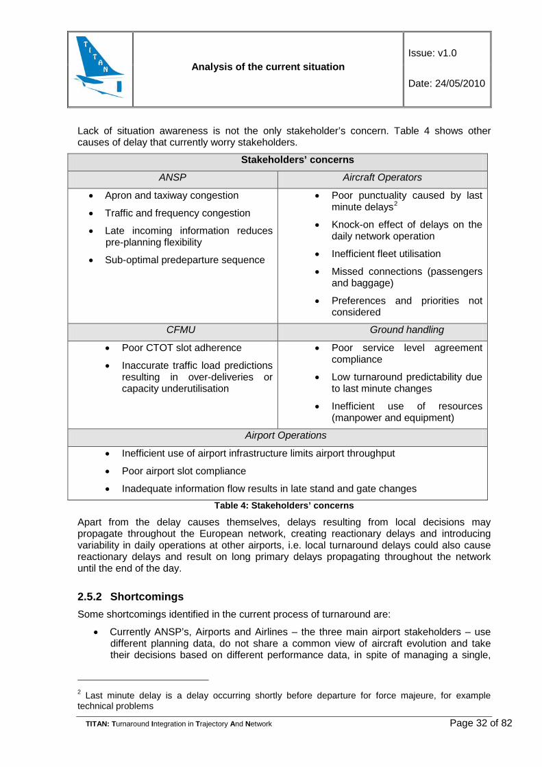
Lack of situation awareness is not the only stakeholder’s concern. Table 4 shows other causes of delay that currently worry stakeholders.
Stakeholders’ concerns
ANSP Aircraft Operators
• Apron and taxiway congestion
• Traffic and frequency congestion
• Late incoming information reduces pre-planning flexibility
• Sub-optimal predeparture sequence
• Poor punctuality caused by last minute delays2
• Knock-on effect of delays on the daily network operation
• Inefficient fleet utilisation
• Missed connections (passengers and baggage)
• Preferences and priorities not considered
CFMU Ground handling
• Poor CTOT slot adherence
• Inaccurate traffic load predictions resulting in over-deliveries or capacity underutilisation
• Poor service level agreement compliance
• Low turnaround predictability due to last minute changes
• Inefficient use of resources (manpower and equipment)
Airport Operations
• Inefficient use of airport infrastructure limits airport throughput
• Poor airport slot compliance
• Inadequate information flow results in late stand and gate changes Table 4: Stakeholders’ concerns
Apart from the delay causes themselves, delays resulting from local decisions may propagate throughout the European network, creating reactionary delays and introducing variability in daily operations at other airports, i.e. local turnaround delays could also cause reactionary delays and result on long primary delays propagating throughout the network until the end of the day.
2.5.2 Shortcomings Some shortcomings identified in the current process of turnaround are:
• Currently ANSP’s, Airports and Airlines – the three main airport stakeholders – use different planning data, do not share a common view of aircraft evolution and take their decisions based on different performance data, in spite of managing a single,
2 Last minute delay is a delay occurring shortly before departure for force majeure, for example technical problems
Analysis of the current situation Issue: v1.0
Date: 24/05/2010
TITAN: Turnaround Integration in Trajectory And Network Page 33 of 82
unique set of aircraft which must be loaded and unloaded with a single contracted number of passengers and goods;
• The turnaround is not integrated in the overall planning process;
• Overall poor information sharing and management prevents efficient coordination between all stakeholders resulting in a less effective use of available assets and therefore increasing the hidden costs to the airspace users in the form of operational inefficiencies, such as a non-optimised turnaround process;
• As there is no integrated planning of the turnaround process itself (airside and landside), the precise predictability of the flight’s estimated off-block time is generally poor. Furthermore, the lack of the CDM process the departure planning is not adequate;
• Due to the increasingly demanding security procedures many airports have difficulties in providing adequate infrastructure and resources to allow for short aircraft turnaround times. While this issue can only be resolved by new and harmonized regulations it has a direct negative influence on the ATM operations as it produces additional delays;
• Many stakeholders working at airports use their own codification, tools and applications in order to deliver their specific services. This variety of actors involved and different codification make it difficult to use the information by various parties. There is a need for unification of data coding;
• It is of utmost importance that the relevant stakeholders involved in the turnaround have the knowledge of current position and purpose of all vehicles involved in providing services to aircraft.
According to SESAR, the AOC (Airport Operation Centre) will have reliable information to coordinate and optimize the services provided to different aircraft. However, the interconnection between the services will be subject to different levels of difficulties dependant on the size of the airports.
• The number of actors involved in aircraft services may be very high especially at main international airports. All the stakeholders have their own constrains and their strategy to manage efficiently their part of the process. The integration of their planning activities and procedures is too complex to achieve;
• At medium size airports, the number of partners involved is lower and the different airlines which use the airport may share some services through the same company. This makes the exchange of information less complex and the lower level of the traffic makes that the system to support these operations interconnects fewer applications;
• At minor airports, there is no particular problem in integrating the services since the operations will generally be focussed on a single aircraft at a time.
2.6 Analysis of times
2.6.1 Buffer time concept All turnaround processes are scheduled against the Scheduled Time of Arrival (STA) and, by assuming a dedicated taxi-in time, against the in-block times at the assigned stand, either remote or at the terminal building according to the airport stand allocation scheme. All

Analysis of the current situation Issue: v1.0
Date: 24/05/2010
TITAN: Turnaround Integration in Trajectory And Network Page 34 of 82
disruptions occurring at the inbound sequence unavoidably cause some damage in the ground operations since personnel resources are tight and tools are partly specific for aircraft types. Therefore, the aircraft turnaround performance relies on a robust stand and aircraft allocation scheme over the day.
To achieve the performance targets, the airline operator typically introduces time buffer onto technical minimum gate times. These buffers seem not to follow rigid rules neither to apply a systematic concept but are calibrated to expert knowledge and worked out during the operation. Further, the technical minimum gate time itself is not a constant value per type of aircraft but considers additional aspects such as:
• Belly freight onboard or passengers only for in/outbound or both;
• Inbound from a HUB airport or a secondary airport;
• Outbound to a HUB airport or a secondary airport.
In addition, buffer time is affected by the following factors:
• Location of the airport facilities: the distance between the stand and the housing of the handling equipment;
• Qualification of the involved staff;
• Quantity and quality of the handling equipment;
• Inadequate handling procedures.
The concept of scheduling buffer time into the aircraft turnaround time is introduced at the expense of reducing aircraft productivity to minimize system costs from operational uncertainties. So, the proper use of schedule buffer time can minimize system costs by balancing trade-offs between schedule punctuality and aircraft utilization by employing potential flight hours as a punctuality buffer.
The optimal schedule time for a turnaround aircraft depends on the arrival pattern of inbound aircraft as well as the scheduling strategy of an airline. When the expected delay cost is relatively lower than the operating cost of an airline, the airline might choose to minimize the turnaround time to reduce operating costs and to increase fleet productivity. However, when the schedule buffer time is available due to a low probability of having long-delayed flights, the airline could utilize the schedule buffer time to reach the system optimum without compromising punctuality performance.
To fully understand the concept behind buffer time, here there is an example of its use: it is known that the cleaning of the aircraft will take “y” minutes while the whole process is planned to take “x” minutes. Then x=y+t, where “t” means the time buffer.
Cleaning of the aircraft
x
y t
The planned time buffer allows a slight delay in the start of the cleaning process. The maximum delay that the system can tolerate without compromising the termination of the subsequent processes in due time is “t”. Knowing that the cleaning process needs “y” time to be finished, if the delay at start exceeds “t”, the next processes (which is dependent on the previous one) will probably suffer a slip (unless it also has a time buffer that can be consumed in favour of the cleaning process).

Analysis of the current situation Issue: v1.0
Date: 24/05/2010
TITAN: Turnaround Integration in Trajectory And Network Page 35 of 82
It has been observed that the arrival lateness did not necessarily result in departure delays, unless arrival delay was longer than the scheduled buffer time in turnaround schedules. The schedule buffer time is used to absorb arrival delays, unexpected departure delays due to ground handling disruptions and to accommodate inevitable time gaps in flight schedules.
The influence of the arrival punctuality of inbound aircraft is found to be significant on the departure punctuality of turnaround aircraft. Therefore, it is recommended that the scheduling of turnaround aircraft should consider the individual punctuality performance of each route, and different schedule buffer time should be applied on different routes with different punctuality behaviour.
Last, buffer times could be introduced for the turnaround as a whole or, more specifically, in between the processes along it. The question of the best time buffer to cope with both aspects is crucial. According to queuing theory, the buffer will further be dependent on the delay magnitude of an individual turnaround, expressing the fact that late aircraft may most probably need less buffer time due to an increasing pressure on all actors to catch up with the schedule.
2.6.2 Buffer time estimation Buffer time associated to the turnaround process has been estimated through a thoroughly analysis of a database owned by AENA which shows actual turnaround operation times of different flights, airports, airlines, ground handling agents and aircraft types.
The database is populated with 110 aircraft flying to/from several European airports. In all cases, the origin or the destination of the flight is Spanish airports, where the start and end times of the different turnaround processes have been collected. The corresponding load factor of the aircraft in terms of real number of boarded passengers appears in Figure 6 where it is shown that 86% of the assessed aircrafts were occupied by a maximum of 260 passengers.
4% 10%
47%
19%
20%
> 350 pax261 - 350 pax166 - 260 pax101 - 165 pax0 - 100 pax
Figure 6: Sample of aircrafts
No difference has been established in this study between low cost and regular carriers as differences found in the buffer time analysis were not considered relevant.
As explained in previous sections in this document, the turnaround process involves many actors and actions. The provided ground services are not independent one from the other as a number of them have to be processed, in sequence, to provide service to the aircraft. The methodology followed to estimate the buffer time is based on this premise and buffer times

Analysis of the current situation Issue: v1.0
Date: 24/05/2010
TITAN: Turnaround Integration in Trajectory And Network Page 36 of 82
are calculated by adding the gaps3
In this study, the activities
(minutes) between those activities that are consecutive and should be ideally performed one immediately after the other but are not in the reality.
4
1. Position passengers bridges or stairs;
and assumptions considered have been:
2. Deplane passengers: activities 1 and 2 are performed either one immediately after the other or with a buffer time between them. It is assumed that in ideal conditions passengers start to deplane aircraft at the same instant that the bridge/stairs are placed;
3. Service cabin, service galleys and fuel airplane: there is not an established sequence between these three activities so this assessment considers the earliest start (following activity 2) and the last end (followed by process 4) in order to calculate the buffers;
4. Board passengers; activities 4 and 5 are performed either one immediately after the other or with a buffer time between them;
5. Remove passenger bridges or stairs. It is assumed that in ideal conditions passengers finish to board aircraft at the same instant that the bridge/stairs are removed.
Loading and cargo activities have been excluded of the previous list because they can always be performed simultaneously to some of the previous aircraft and passenger services so they are not considered to be part of the critical processes during the turnaround. Because of their short relevance in the whole process other activities such as servicing vacuum toilets and servicing potable water have not been taken into account.
3 Time gap is “t” in the example of Section 2.6.1 4 The duration of the collected activities is “y” in the example of Section 2.6.1

Analysis of the current situation Issue:v1.0
Date: 24/05/2010
TITAN: Turnaround Integration in Trajectory And Network Page 37 of 82
POSITION DEPLANE PASSENGERS
REMOVE / POSITION SERVICE GALLEYS REMOVE
POSITION REMOVESERVICE CABIN
BOARD PASSENGERS REMOVE
PASSENGER SERVICES
POSITIONAIRPLANE SERVICES FUEL AIRPLANE REMOVE
Buf
fer 1
Buf
fer 2
Buf
fer 3 Buf
fer 4
Figure 7: Buffer time estimation

Analysis of the current situation Issue: v1.0
Date: 24/05/2010
TITAN: Turnaround Integration in Trajectory And Network
This sequence of activities and the possible “gaps” between them that will be used for the estimation of buffer times are shown in Figure 7 which is based on B737 aircraft. The addition of these time gaps is the buffer time corresponding to one particular aircraft. It should be understood as the minimum buffer as part of the originally scheduled one could have been spent to absorb delays or inefficiencies of any process. The results are represented in the following histogram:
0%
5%
10%
15%
20%
25%
30%
35%
40%
45%
10 20 30 40 50 60 70 80
Buffer time (Minutes)
Airc
raft
Discarded values
Figure 8: Buffer time histogram
Those flights with a buffer time higher than 30 minutes are not considered to be representative as this time corresponds to long rotations where the notion of buffer time could be mistaken with a slow downed turnaround process. Taking into account the rest of flights the aircraft sample adds up to 95% of the total.
With these values discarded the following histogram (ordinary and cumulative) shows the number of aircraft associated to a certain buffer time on its turnaround. It can be concluded that the majority of turnarounds have a buffer time varying between 5 and 14 minutes while the mean buffer time is 12 minutes. Also 90% of the aircraft has a buffer time of 22 minutes or less.

Analysis of the current situation Issue: v1.0
Date: 24/05/2010
TITAN: Turnaround Integration in Trajectory And Network Page 39 of 82
0,0%
2,5%
5,0%
7,5%
10,0%
1 2 3 4 5 6 7 8 9 101112131415161718192021222324252627282930
Buffer time (Minutes)
Airc
raft
0%
10%
20%
30%
40%
50%
60%
70%
80%
90%
100%
Figure 9: Post-processed buffer time histogram
The main conclusion of this analysis is the confirmation through real collected data of the existence of certain time gaps between the different ground operations involved in the turnaround process. The quantitative values should be read together with the assumptions adopted in this methodology and should be understood as a guidance for future assessments rather than an absolute value.
2.6.3 Buffer time and milestones As previously indicated, during the turnaround process a number of ground operations have to be processed in sequence to provide service to the aircraft. These processes are scheduled against the Scheduled In-Block Time (SIBT). All disruptions occurring during the turnaround cause slip in the ground handling services since the processes partly dependent on each other, the personnel resources are tight and tools are fairly specific for aircraft types,
Buffer times and milestones are closely linked in order to support a better decision making process. The example described hereafter reflects how this milestone approach takes benefit of the existence of buffer times:
The check-in starts in time and also the security process (M1). The aircraft arrives in time to its stand and the de-boarding starts (M5). During this process one of the passengers for unknown reasons doesn’t disembark in time (consider the case of wheel-chair passenger for instance), which causes a delay in the start of the aircraft services (M6). The responsible person can update this figure in the appropriate system, which allows the partners to re-allocate the resources. The use of the time-buffer in the disembarking process also prevents the delay of the other services and of the departing flight.
When the aircraft services have finally started, the following causes can produce a slip:
1. A sensitive part of the aircraft activities is often the catering replenishment, as it lasts the longest time, although the passengers can start the boarding using the first door while the catering exchange is executed at the back of the aircraft;
2. A delay in the cleaning of the aircraft can also cause the slip of the turnaround process, as the boarding cannot start until it is not finished. In case of low cost carriers the cleaning is usually done by the flight attendants and usually lasts a shorter time;
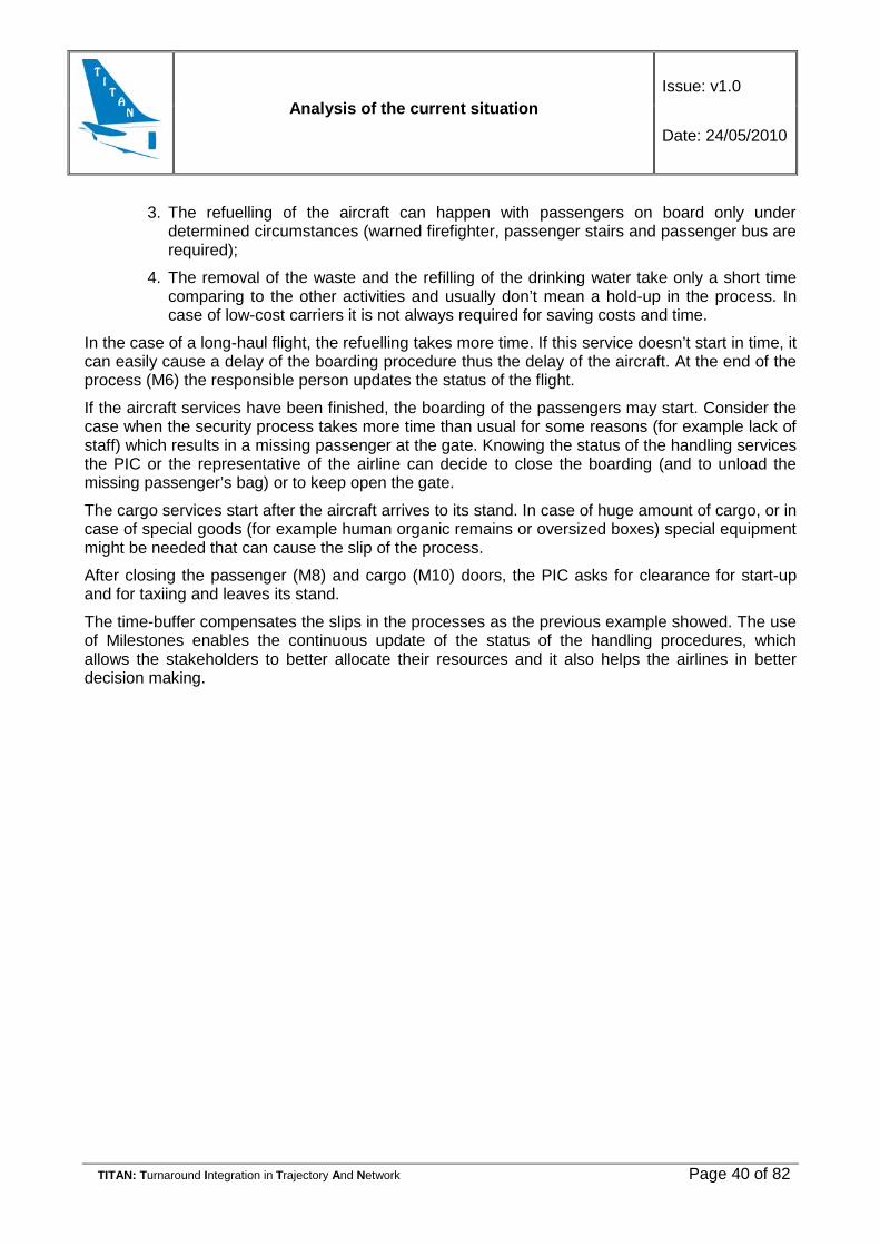
Analysis of the current situation Issue: v1.0
Date: 24/05/2010
TITAN: Turnaround Integration in Trajectory And Network Page 40 of 82
3. The refuelling of the aircraft can happen with passengers on board only under determined circumstances (warned firefighter, passenger stairs and passenger bus are required);
4. The removal of the waste and the refilling of the drinking water take only a short time comparing to the other activities and usually don’t mean a hold-up in the process. In case of low-cost carriers it is not always required for saving costs and time.
In the case of a long-haul flight, the refuelling takes more time. If this service doesn’t start in time, it can easily cause a delay of the boarding procedure thus the delay of the aircraft. At the end of the process (M6) the responsible person updates the status of the flight.
If the aircraft services have been finished, the boarding of the passengers may start. Consider the case when the security process takes more time than usual for some reasons (for example lack of staff) which results in a missing passenger at the gate. Knowing the status of the handling services the PIC or the representative of the airline can decide to close the boarding (and to unload the missing passenger’s bag) or to keep open the gate.
The cargo services start after the aircraft arrives to its stand. In case of huge amount of cargo, or in case of special goods (for example human organic remains or oversized boxes) special equipment might be needed that can cause the slip of the process.
After closing the passenger (M8) and cargo (M10) doors, the PIC asks for clearance for start-up and for taxiing and leaves its stand.
The time-buffer compensates the slips in the processes as the previous example showed. The use of Milestones enables the continuous update of the status of the handling procedures, which allows the stakeholders to better allocate their resources and it also helps the airlines in better decision making.

Analysis of the current situation Issue: v1.0
Date: 24/05/2010
TITAN: Turnaround Integration in Trajectory And Network Page 41 of 82
3. CONFLICTS IN THE TURNAROUND In a complex system like the turnaround process there are a multitude of activities that can go wrong. Most of these activities are linked through a network of direct and indirect relationships; as a result, a failure can turn into a general delay.
Failures come from two differences sources:
1. Internal: directly related to the turnaround process and usually consisting of an inefficient handling service (mobile trucks are late, inaccurate marshalling, etc). The timing of the turnaround considers the probability of an incident to happen and the impact of a poorly handling performance for that reason, internal failures do not often became into a conflict.
2. Boundary: involve all these events that usually affect to the turnaround, for example a new gate allocation, ice on taxiways or emergency procedures. These situations cannot be controlled by ground-handlers and cause a high impact on the scheduled planning of the activities. These boundary failures will be classified attending to the cause that provoke them:
• Adverse meteorological conditions (thick fog, iced taxiways);
• Emergency or unexpected situation (engine failure, , urgent delivery5
Hereafter a thorough description is given of the possible situations that could generate a delay. This description enables the identification of the possible improvements to integrate into the Turnaround Operational Concept which will minimise the impact of poorly managed handling activities. Turnaround activities have been considering the agents are described below:
)
Table 5 On Ramp On board services External ramp Ramp services
Fuelling Exchange of blankets, pillows
Passenger handling (stairs, mobile lounge)
Supervision
Toilet/mineralized water
Locating Catering Mail loaders Marshalling (signal man/docking)
electric power supply Restocking seatback pocket
Catering loaders Towing/Push back
Fault servicing (report minor faults)
Cleaning astrays and removal of littler
Load Flow of terminal Start-up
Wheels and tires (checking of wheels
and tires
Alteration of seat configuration
Cargo Loaders Safety measures
De-icing. Vacuuming carpets
Washing aircraft Cleaning galleys and toilets
Table 5 Turnaround activities.
5 Urgent delivery: We understand urgent delivery as human organs/blood and spare engine parts.

Analysis of the current situation Issue: v1.0
Date: 24/05/2010
TITAN: Turnaround Integration in Trajectory And Network Page 42 of 82
Figure 10: Boundary Conflicts
3.1 Internal Conflicts In most airports turnaround activities (Table 5) are carried out by private companies. These companies provide a specific service (cargo handling, passenger assistance to the aircraft, ramp services, etc) to the airlines. The performance of the ground handler depends on the contract with the airline.
Airline is aware of the importance of an efficient turnaround process, as lost baggage, poor conditioning of the cabin or even a short delay can cause negative impacts on the airline’s reputation. For that reason, air carriers impose strict constrains on the ground handler performance. Often the airlines impose average time and a tolerance time to perform the services.
• The average time is calculated considering the type of aircraft, location of the apron, facilities provided by the airport and the required quality of the service;
• The tolerance time depends on the probability of an incident, expected impact of the incident on the turnaround process and mitigation procedures of the ground-handling companies. In case of exceeding the tolerance time, the ground-handling companies will be fined6.
Figure 11: Average Time
If turnaround activities are performed in the correct order, following the scheduled planning, the delays caused by late activities are often compensated by a fast achievement of the following ones; however, if the disruption comes from the boundary conflicts, turnaround can face a linked delay.
Internal conflicts are further described in the following sections.
6 Please note that buffer time and tolerance time refer to the same fact, expressions came from different backgrounds, theoretical or empirical backgrounds.
Analysis of the current situation Issue: v1.0
Date: 24/05/2010
TITAN: Turnaround Integration in Trajectory And Network Page 43 of 82
3.1.1 Reckless Driving Airlines demand a shortest turnaround times which often compels ground-handlers not to meet safety regulations. Reckless driving has become into a habit, speed is often double than allowed and collision between vehicles on the apron is a common incident. This causes a delay on the equipment needed to provide certain turnaround services to an aircraft.
3.1.1.1 Crossing forbidden areas
Driving under aircraft wings without the Supervisor Engineer7
clearance or trespassing platform taxiways are common ways to cut down distance on the apron which increases the probability of a collision and consequently causes a general delay of the turnaround process.
Figure 12: Crossing forbidden areas
Source: “Normativa de seguridad en plataforma” - AENA
Collision with the back of the wings is a common incident; usually a ground handler, on hurry to start their activity, asks clearance to the Supervisor Engineer for passing under wings, the Supervisor can be busy and ground handler just crosses and collides with the aircraft.
Crossing forbidden areas Actors Vehicles involved in the turnaround processes Reason Stress to meet a strict timed schedule Consequences Increase on dangerous manoeuvring
Increase of damage to the aircraft Collision with other handling vehicles
Side effects Accidents Delay in the turnaround activities Flight delayed
Table 6: Crossing forbidden areas
7 Supervisor Engineer. Member of “Ramp services” is charge of the safety on the stand. Note that the name and the duties can slightly change depending on countries an airport policies.

Analysis of the current situation Issue: v1.0
Date: 24/05/2010
TITAN: Turnaround Integration in Trajectory And Network Page 44 of 82
3.1.1.2 Reckless Driving on Platform
It is common on taxiways joining terminal building to remote aprons. Turnaround vehicles drive as fast as possible which makes difficult to give way to other vehicles. Most of handling vehicles are provided with anti-collision sensors; which usually help drivers to reduce the speed before collision.
Reckless Driving on Platform Actors Vehicles involved in the turnaround processes Reason Stress to meet a strict timed schedule Consequences Increase on dangerous manoeuvring
Collision into other handling vehicles Disturbance to other vehicles
Side Effect Accidents Delay in the turnaround activities Flight delayed Table 7: Reckless Driving on Platform
Figure 13: Reckless Driving on Platform
Source: “Normativa de seguridad en plataforma” - AENA
3.1.1.3 Parked or stopped vehicle in a forbidden area
On the apron the handling vehicles must be located on EPA (equipment parking area) or in ESA (equipment standing area). Due to low visibility conditions, snow on the apron, thick fog, etc, the vehicles involved in the handling activities which are not located on EPA or ESA cause troubles to other ground handlers.
Figure 14: Vehicle standing outside EPA and ESA
Source: “Normativa de seguridad en plataforma” - AENA
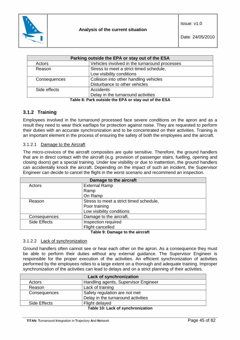
Analysis of the current situation Issue: v1.0
Date: 24/05/2010
TITAN: Turnaround Integration in Trajectory And Network Page 45 of 82
Parking outside the EPA or stay out of the ESA Actors Vehicles involved in the turnaround processes Reason Stress to meet a strict timed schedule,
Low visibility conditions Consequences Collision into other handling vehicles
Disturbance to other vehicles Side effects Accidents
Delay in the turnaround activities Table 8: Park outside the EPA or stay out of the ESA
3.1.2 Training Employees involved in the turnaround processed face severe conditions on the apron and as a result they need to wear thick earflaps for protection against noise. They are requested to perform their duties with an accurate synchronization and to be concentrated on their activities. Training is an important element in the process of ensuring the safety of both the employees and the aircraft.
3.1.2.1 Damage to the Aircraft
The micro-crevices of the aircraft composites are quite sensitive. Therefore, the ground handlers that are in direct contact with the aircraft (e.g. provision of passenger stairs, fuelling, opening and closing doors) get a special training. Under low visibility or due to inattention, the ground handlers can accidentally knock the aircraft. Depending on the impact of such an incident, the Supervisor Engineer can decide to cancel the flight in the worst scenario and recommend an inspection.
Damage to the aircraft Actors External Ramp
Ramp On Ramp
Reason Stress to meet a strict timed schedule, Poor training Low visibility conditions
Consequences Damage to the aircraft. Side Effects Inspection required
Flight cancelled Table 9: Damage to the aircraft
3.1.2.2 Lack of synchronization
Ground handlers often cannot see or hear each other on the apron. As a consequence they must be able to perform their duties without any external guidance. The Supervisor Engineer is responsible for the proper execution of the activities. An efficient synchronization of activities performed by the employees relies to a large extent on a thorough and adequate training. Improper synchronization of the activities can lead to delays and on a strict planning of their activities.
Lack of synchronization Actors Handling agents, Supervisor Engineer Reason Lack of training Consequences Safety regulation are not met
Delay in the turnaround activities Side Effects Flight delayed
Table 10: Lack of synchronization

Analysis of the current situation Issue: v1.0
Date: 24/05/2010
TITAN: Turnaround Integration in Trajectory And Network Page 46 of 82
3.1.3 Poor Maintenance Poor maintenance of the ground handling equipment causes unexpected conflicts and a mayor delay of the whole process this is especially noticeable during the winter and on the remote aprons.
3.1.3.1 Fuel on the apron
Hydrant hoses must accurately fit on the entrance mouth; if the hose is not properly fixed fuel can drop on the apron. In this case, the Supervisor Engineer will remove vehicles from the stand and will ask for cleaning services. Flight will be delayed
Split fuel on the apron Actors Supervisor Engineer
Ground-Handling worker Reason The hose does not fit property
Stress to meet a strict Low visibility due to fog or rain avoids worker to notice the dropping
Consequences Safety procedures are deployed to clean the fuel on the apron Handling is stopped
Side Effects Delay in the turnaround activities Flight delayed
Table 11: Split fuel on the apron
3.1.3.2 Remote aprons
Maintenance service providers are responsible for the proper functioning of the equipment. A failure can lead to a delay. This is applicable particularly to an aircraft standing on a remote apron which requires mobile trucks.
Please note that the ground handling team waiting for an aircraft will not assist to a nearby aircraft. Any aircraft missing a service will wait until new equipment arrived from terminal.
Table 12: Conflicts on remote aprons
3.1.4 Passenger
3.1.4.1 Missing Passenger
A missing passenger is a common issue in the airport. Passengers could be missed because of a problem when accessing the airport (e.g. traffic jam, railway strike, railway technical problem), late check-in, too long queues in the security process, last minute change of the gate, information not well displayed in the airport, terminal shopping, etc. All these causes have their origin in the landside activities.
Airlines usually consider this incident in their timing schedule and that not cause a major delay. Once the staff in the gate noticed a missing passenger, external ramp ground handler, still on the stand, must unload the baggage.
Conflicts on Remote Aprons Actors External Ramp ,Ramp, On Ramp, On board Reason Poorly maintenance Consequences Flight delayed Side effects Flight delayed

Analysis of the current situation Issue: v1.0
Date: 24/05/2010
TITAN: Turnaround Integration in Trajectory And Network Page 47 of 82
Late or missed passenger Actors Passenger
External Ramp ground handler Reason Missed last call Consequences Find the baggage and remove it Side effects Almost none, airline companies considers that issue on the
slot planning. Table 13: Late or missed passenger
3.1.4.2 Special Passenger Procedures
Passengers requiring special attention, like wheel chair or kids alone, are usually asked to inform to the airline about this situation as soon as possible, however most passengers wait until arriving to the information desk for applying to these facilities. As a consequence, ground handler must add a new activity to their scheduled plan, which can cause a delay in the whole process.
Special Passenger Procedures Actors Airport, Passengers Reason Lack of prevision (wheel chair, kids alone) Consequences Poorly handling Side Effects No side effects
Flight delayed Table 14: Special passenger procedures
3.1.5 Baggage Lost or damage baggage have a negative impact on the passenger perception of airline or airport. For this reason, companies pay special attention to this issue
3.1.5.1 Lost Baggage
Baggage in transfer can be lost relatively easily comparing to the destination baggage. This baggage should be packed separately from the destination baggage and placed in different ULDs. If the deck does not have enough space, the baggage in transfer can be loaded in the same ULD as destination baggage. At the end of the scale, baggage handlers will have to separate two types of baggage. The time pressure or high volume of baggage can lead to putting the baggage in the wrong place.
Lost Baggage Actors Porters, carriers Reason Mixed baggage types (transfer and destination) in the same
ULD Cargo Sheet is not checked due to stress to meet a strict timing
Consequences Transfer Baggage is brought to baggage reclaim hall Lost Transfer Baggage is detected by supervisors before put them on baggage belts Lost Transfer is reclaimed by flight porters
Secondary effects Delay in the turnaround activities Flight delayed Passenger not satisfied
Table 15: Lost baggage

Analysis of the current situation Issue: v1.0
Date: 24/05/2010
TITAN: Turnaround Integration in Trajectory And Network Page 48 of 82
3.1.5.2 Dropped Baggage
A common cause of lost of baggage is the mishandling during the transportation. Baggage is dropped from lorry and remains left on the manoeuvring area. It can lead to two different problems:
• Fallen Baggage is lately found and ground handlers must come back to the apron to take it which causes delays on their scheduled activities.
• Fallen Baggage is found after the flight has left. Passenger will recover its baggage after a few days.
Dropped Baggage Actors Porters/ lorries drivers Reason Mishandling Consequences Baggage fallen from the lorries
Baggage dropped from aircraft Lorry comes back to pick the fallen baggage
Secondary effects Accidents Delay in the turnaround activities Flight delayed Passenger not satisfied
Table 16: Dropped baggage
3.1.6 Winter Procedures
3.1.6.1 Poor conditioning of the facilities
Safety operations during winter require specific equipment and procedures. Before the winter, maintenance service achieves an inspection of turnaround vehicles checking tires, ignition performance under cold temperature and fog headlights. Pavement apron is also checked and fixed. Signals on the pavements and mark lights must be also reviewed to ensure a right position of the handling vehicles and a correct taxiway and runway lines.
These procedures are not always correctly carried out and when adverse weather conditions starts the vehicles have to operate slower due to a deficient illumination or a low road holding to the pavement. The brilliance of mark light on pavement is often forgotten or poorly checked.
Low visibility together with poor maintenance of the facilities can cause improper positioning of vehicles.
Poor maintenance of the facilities Actors Maintenance service providers Reason Facilities are poorly checked Consequences General Handling services are slower
Crash between turnaround vehicles due to aquaplaning and ice on apron Pavement marks are not visible due to the snow, vehicles are in an incorrect position and turnaround activities are held up. Crashing between handling vehicles and aircraft result in the necessary check of aircraft
Secondary effects Flight delayed Flight cancelled
Table 17: Poor maintenance of the facilities

Analysis of the current situation Issue: v1.0
Date: 24/05/2010
TITAN: Turnaround Integration in Trajectory And Network Page 49 of 82
3.1.6.2 Environmental Control System
Under extreme hot or cold temperatures aircraft cabin must remain conditioned during the turnaround. The ECS (Environmental Control System) is responsible for pumping the conditioned low pressure air into the cabin during the whole turnaround process.
If the temperature in the passenger and crew cabin is not adequate, the flight will be delayed until the conditions meet the satisfying health regulations.
ECS Actors On ramp Reasons ECS starts late.
Malfunction of ECS equipment Consequences Cabin is not properly conditioned. Side Effects Passenger will be uncomfortable
Crew cabin is not conditioned Flight delayed Flight cancelled
Table 18: Environmental Control System
3.2 Boundary Conflicts Currently, the major disruptions in the turnaround process are not caused by the interaction between the turnaround activities but by the “external agents”. External agents, like air traffic controllers or meteorological service, are not related with turnaround activities, but these agents can have an impact on turnaround performance. Turnaround delay resulting from a poor handling process is uncommon. On the airside, the activity turnaround plan causes the majority of disruptions due to several reasons. As you can see in the Handling Hazard Analysis, conflicts are not an isolated issue.
Table 19: Process code
Service Colour code
Ramp service Purple
On ramp Service Pink
External ramp service Deep Green
Pilots Deep Blue
Maintenance Light Blue
Airport operators Grey
Air Controllers Orange

Analysis of the current situation Issue: v1.0
Date: 24/05/2010
TITAN: Turnaround Integration in Trajectory And Network Page 50 of 82
Service Colour code
On board Light Green Table 20: Colour code
3.2.1 Wet pavement The presence of liquid contaminants causes wet pavement. The inadequate state of the pavement or aquaplaning cause slips which can hinder operations related to aircraft. This may disrupt the scheduled turnaround activities and it may in the end result in flights delays.
For this reason, the maintenance service providers check the pavement status and remove any debris or contaminants before any incident/accident occurs. Normally, handling trucks (e.g. towing or push-back vehicles) detect wet pavement with the use of a sensor installed at the front of the vehicle.
Delays caused by the temporary closing of a runway/taxiway/apron being a result of scheduled cleaning services resulting from expected situation. A prompt reaction of the maintenance service providers enables the GMC (Ground Movement Controller) to execute some mitigation actions (proactively) optimizing the handling services and as a result minimizing delays.
Firstly, wet pavement can cause a possible engine failure if a stone, sand or any other kind of debris is sucked by the engines. This problem and its consequences are described in depth in the present document (section 3.2.5) and provide a clear example of strong interdependency existing between the sources of problems in the turnaround process.
Secondly, slipping or aquaplaning can even cause a crash. If the pilot is able to avoid an accident but he cannot keep the control of the aircraft, the aircraft could slide off its way and cross the nearby runways/taxiways/aprons. Thus, GMC must stop or change the direction of other aircraft and handling vehicles operating in the area. The affected aircraft might be delayed, the handling vehicles might be late in executing their scheduled activities and cause a chain delay. Even if the pilot is in control of the aircraft, the assistance vehicles will be required and therefore the services of handling providers might not be on time.
The pilots of an aircraft ready for landing can be asked to remain in the holding stack or they can be asked to change the originally allocated runway. This might cause the necessity of readjusting the schedules and land use of the handling services. See Figure 21 in the Appendix.
3.2.2 Iced Aircraft Under cold weather ice is accumulated on fuselage, tail and a wing. The airplane shape is distorted and free movements of ailerons and flaps are difficult. Traditionally, ice on the surfaces is removed by spraying glycol liquids, FPD (freezing point depressant). GMC (ground movement controller) guides the aircraft towards the de-icing bay, where an operator of a truck sprays the aircraft with a de-icing liquid. Once the air-surfaces have been cleaned, the aircraft awaits the clearance for a take off.
FPD Type I is relatively popular in the airports located in the South where temperatures are not so cold and de-icing is hardly necessary. This type of FPD is reasonably affordable and can be stored easily. Unfortunately, the holdover time (time during the surface remains de-iced after being sprayed) is short and the aircraft needs an immediate clearance for a take off. If the runways or taxiways are covered with ice, the aircraft will be asked to remain at the holding point while the maintenance service provider cleans the surfaces. After a few minutes, ice re-crystallises again
Analysis of the current situation Issue: v1.0
Date: 24/05/2010
TITAN: Turnaround Integration in Trajectory And Network Page 51 of 82
and the aircraft must return to the de-icing bay where the process of de-icing the aircraft with the use of the FPD is applied once again. This delay of a single aircraft, however, creates a chain reaction which affects not only aircraft delays at the airport in stake, but also has impact on the connecting flights.
As a solution, FPD Type II and Type IV have been developed. They are characterized by a longer holdover time and better de-icing performances. However, both are highly polluting the environment and are not always allowed to be used due to environmental constraints.
An alternative solution is a de-icing hangar. Such a hangar includes a special box with infra-red lamps hanging from the ceiling. Such a hangar is often located as nearly as possible to the threshold enabling the aircraft de-icing just prior to its take off. A medium-sized aircraft can be de-iced in 5 minutes. Such hangars are useful especially airports characterized by very cold temperatures where a long queue of aircraft requires fast de-icing services.
As it can be seen in the diagram below, only de-icing with Type-I-FPD can lead to a general delay, a delay affecting to the whole airport. Cold temperatures often cause a delay in most of the airport operations. Only the usage of an inadequate de-icing method, however, can be attributed to the handling services. It should be also noted that the expected performance of the de-icing services to be provided by a handling company is agreed a priori between the airport operators and the handling providers. It is likely that a southern airport prefers lower quality of de-icing services when compared to a northern airport which should generally decide on a more expensive handling agreement.
It should be also noted that a pavement covered with ice can cause delays at airports as it was mentioned in section 3.2.7.1.

Analysis of the current situation Issue: v1.0
Date: 24/05/2010
TITAN: Turnaround Integration in Trajectory And Network Page 52 of 82
DE-ICING
De-icing using Type I liquid
On Ramp Services
De-icing using Type IV or Type II
liquid
On Ramp Services
Aircraft is required to wait on a
holding point
GMCAircraft on the holding point re-iced
Quite cold temperaturesOut of holdover time
Aircraft is inmedialty allowed
to take off
LCL
Flight on time
Aircraft on the holding point is not re-iced
Aircraft is required to wait on a
holding point
GMC
Aircraft is allowed to take off
LCL
De-icing in a deicing hangar
On Ramp Services
Aircraft on the holding point does
not re-ice
Flight delayed
Aircraft must be deiced again
There are more aircrafts waiting for being de-iced
aircraft is guided towards the deicing bay
GMC
There are no more aircrafts waiting on
the deicing bay
Aircraft is deiced
Flight delayed
Deicing is ready
On Ramp services
De-icing vehicle arrives late, lack of
FDP, ...
On Ramp services
Figure 15: Iced Aircraft

Analysis of the current situation Issue: v1.0
Date: 24/05/2010
TITAN: Turnaround Integration in Trajectory And Network Page 53 of 82
3.2.3 Unknown Position Turnaround activities are easily affected by low visibility conditions. On the manoeuvring area, the GMC is in charge of guiding both aircraft and handling vehicles. This guidance is achieved by radio-communication; the ground controller can guide vehicles by lighting marks in the pavement. Under heavy rain or thick fog vehicle speed is reduced and the provision of handling services delayed. In quite bad conditions the handling driver may even not be able to see the lighting marks; the handling vehicle will be stopped and the taxiway closed until an emergency vehicle rescues it.
On the apron, vehicles are generally not supported by any guidance and they might be able to achieve their duties without any external help. Most airports are equipped with powerful fog-lamps, however, under quite low visibility conditions, the handling vehicles may crash into others.
Two types of aprons can be identified:
• By the terminal passenger;
• By the satellite terminal.
Handling vehicles providing services to aircraft immediately adjacent to the terminal passenger do not need to cross the apron (except push back/towing and star-up) and they are protected against rain by a covering infrastructure. Crashing in this area is often caused by a higher speed than permitted and usually does not cause a mayor delay on flights. However, satellite terminal requires handling vehicle to move across the manoeuvring area, in such case GMC must control the handling vehicle position, thus crashing does not occur so often.
HANDLING VEHICLE POSITION IS UNKNOWN
Vehicles on maneuvering area
Vehicles on apron
GMC is on charge to mantain the proper distance between vehicles and aircraft and to provide guidance to them
Thick Fog /Heavy rain /
Other causes
Ground controller is not on charge of activities on the apron
Handling vehicle cannot be
managed by GMC
GMC
Vehicled is guided by the GMC
GMC
Handling vehicles can achieve their activites safetly
Handling vehicles
Handlig vehicles cannot provide
services because lack of visibility
Handling vehicles
Handling vehicles communicate with
the ground controller
Handling vehicles
Handling vehicle crashes into
another vehicle or aircraft
Handling vehicles
Handling vehicle stops
Handling vehicles
Handling vehicle cannot provided services to the
aircraft
Handling vehicles
Handling
Handling vehicle cannot provided services to any
aircraft
Handling vehicles
Handling
Handling vehicles are not on time to provide services to
the aircraft
GMC
Handling vehicles are on time to
provide services to the aircraft
GMC
Flight in time
Flight delayed
Flight in time
Flight delayed
Flight delayed
Figure 16: Unknown Position
Analysis of the current situation Issue: v1.0
Date: 24/05/2010
TITAN: Turnaround Integration in Trajectory And Network Page 54 of 82
Currently some technological systems are being developed and implemented to support the monitoring of vehicles on the manoeuvring area, such as A-SGMCS, multilateration or radar surface.
3.2.4 Sick Passenger Sick passenger on board can be considered as an emergency leading to the passenger to be disembarked. Emergency procedures depend on the situation of the aircraft (on air, on the movement area or on the apron) and involve both emergency vehicles and handling services. Dealing on time under this emergency situation is hardly possible although delays cannot be blamed on the handling vehicles but on the general disruption caused in the airport.
Aircraft in the air requires a close cooperation between air controller and the emergency staff of the nearest airport. Air controllers of the new airport must clear a runway and flights prepared to operate on it are delayed. Handling vehicles (e. g. passenger steps, push-back etc.) prior to the attendance of the sick passenger and their scheduled activities will hold up, as a consequence new delays will be generated.
If the aircraft is still on the manoeuvring area, emergency procedures are easily achieved, but often the slot is missed, and aircraft must ask for a new slot allocation.
Special procedures are required in case of diseases considered as quite infections (for example, last year H1N1 forced some flights to be cancelled) and all personal in contact with sick passengers were compelled to quarantine causing a lack of qualified staff due to a non expected situation what impact seriously to the handling schedule.

Analysis of the current situation Issue: v1.0
Date: 24/05/2010
TITAN: Turnaround Integration in Trajectory And Network Page 55 of 82
PASSANGER FALLS SERIOUSLY ILL
Aircraft on apron Aircraft on taxiway Aircraft taking off
Passenger steps and emergency
vehicles
Ramp services
Aircraft on airAircraft taking land
Aircraft must take off
Aircraft can stop inside the (EDA)
Aircraft needs landing
Taking off aborted
Allocate a runway to take land
Air Controller
Aircrafts waiting for taking off are
delayed
Air Controller
Aircrafts in the holding stack are
delayed
Air Controller
Aircrafts wait for clearance
Air Controller
Clearance is late
GMC
Clearance in time
GMCGMC
Handling vehicles can adapt their
schedule
Ramp/External Ramp service
Handling vehicles affected might be
late to their activites
Airport/Handling
Ramp/External Ramp service
Other flights are delayed
Other flights in
time
Below decision Speed
Pilot
Above decision speed
Pilot
Ill passenger and baggage are disembarked
Aircraft is guided to a safe position
to disembark the ill passenger
GMC
Air Controller assigns an airport/
and runway to take land
AC
Aircraft waits for clerance to start to
take off
LCL
Flight delayed
Disease is not dangerous for passengers or
crew
Dangerous InfectiousDisease
Crew and passengers are dissembarked
Aircraft requires desinfection
Flight cancelled
Passenger steps and emergency
vehicles
Ramp services
Aircraft is guided to a safe position to disembark the sick passenger
GMC
Dangerous InfectiousDisease
Disease is not dangerous for passengers or
crew
Aircraft continues flight as
programmed
Aircraft waits for clerance to start to
take off
LCL
Slot is missedSlot is not missed
Flight in time Flight delayed
Passenger is dissembarked
Figure 17: Sick Passenger
Analysis of the current situation Issue: v1.0
Date: 24/05/2010
TITAN: Turnaround Integration in Trajectory And Network Page 56 of 82
3.2.5 Engine Failure Engine failure is a special incident not foreseen in the operation of the airports. Even when the procedures to address it are quite clear, the impact on the handling process can cause a chain of delays.
In the case of an engine failure during the take off and below the decision speed, the operation will be aborted. The aircraft will stop within the Emergency Distance Available (EDA). A towing vehicle will be required to drive the aircraft towards a safe location and a step truck will be sent for the passengers. If the handling vehicles are able to adapt their schedules, this incident will not cause any further delays. If, however, the schedules cannot be changed accordingly, other flights will be delayed as well.
If the engine failure occurs above the decision speed, the aircraft must continue the ascent and ask for allocation of a runaway to land. The Air Controller must clear a runway and aircraft waiting to use it will be delayed. Aircraft in the holding stack might be allocated to other runways or simply delayed.
Any change of the expected position of aircraft requires from the handling services the adaptation of their schedule and can impact the duration of the turnaround process.
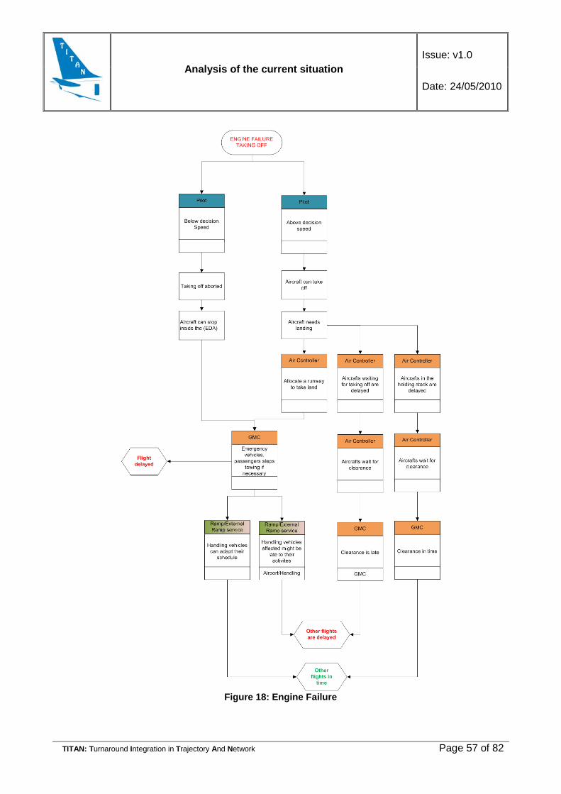
Analysis of the current situation Issue: v1.0
Date: 24/05/2010
TITAN: Turnaround Integration in Trajectory And Network Page 57 of 82
Figure 18: Engine Failure
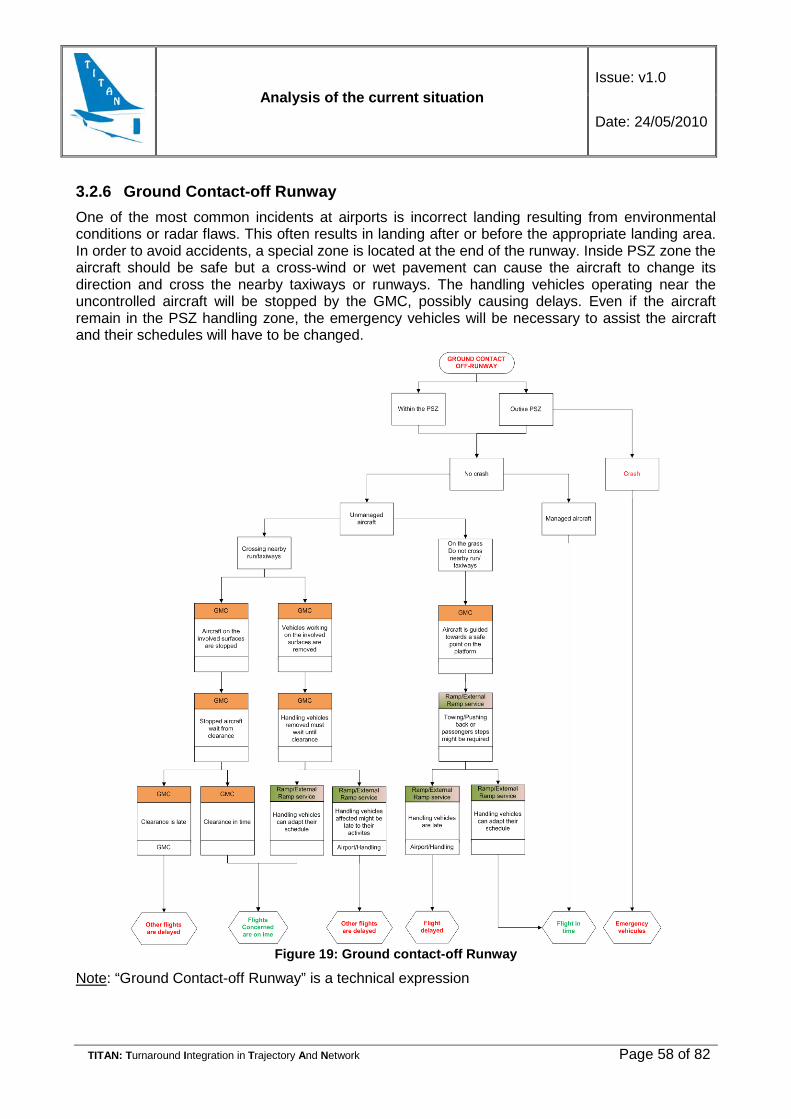
Analysis of the current situation Issue: v1.0
Date: 24/05/2010
TITAN: Turnaround Integration in Trajectory And Network Page 58 of 82
3.2.6 Ground Contact-off Runway One of the most common incidents at airports is incorrect landing resulting from environmental conditions or radar flaws. This often results in landing after or before the appropriate landing area. In order to avoid accidents, a special zone is located at the end of the runway. Inside PSZ zone the aircraft should be safe but a cross-wind or wet pavement can cause the aircraft to change its direction and cross the nearby taxiways or runways. The handling vehicles operating near the uncontrolled aircraft will be stopped by the GMC, possibly causing delays. Even if the aircraft remain in the PSZ handling zone, the emergency vehicles will be necessary to assist the aircraft and their schedules will have to be changed.
Figure 19: Ground contact-off Runway
Note: “Ground Contact-off Runway” is a technical expression

Analysis of the current situation Issue: v1.0
Date: 24/05/2010
TITAN: Turnaround Integration in Trajectory And Network Page 59 of 82
4. INFORMATION SHARING
4.1 Information transfer
4.1.1 Actors The following table indicates the actors involved, their responsibility and the critical points in the turnaround process.
Actor Responsibility
ATC
• control of aircraft taxiing on taxiways and runways;
• control of aircraft descending for landing and taking off ;
• ATC in the terminal area and en-route airspace;
• liaison with the flow management (CFMU).
Aircraft Operator • crew allocation
• Airline schedule management
CFMU • slot allocation
• flow management
Ground handling
• handling of the aircraft
• handling of the passengers
• handling of the baggage/cargo/mail
Airport Operation
• terminal management, check-in counters,
• departure lounges, baggage belts and reclaims;
• provision and allocation of stands and gates,
• guidance and control of vehicles and aircraft on the apron (Apron Control), including provision and operation of follow-me cars and marshallers where required;
• provision and allocation of buses to transfer passengers to remote stands, wheel-chairs, facilities disabled passengers
• towing operations( allowed by LCL controller, performed by airport operators9;
• provision of de-icing facilities
Table 21: Actors and their responsibility
4.1.2 Information transfer between partners A certain piece of information is held by different groups at different airports and is managed and used differently depending on the customs of the procedures of the party concerned. As a result a

Analysis of the current situation Issue: v1.0
Date: 24/05/2010
TITAN: Turnaround Integration in Trajectory And Network Page 60 of 82
given organisation will see a “different part of the same picture”, leading it to manage the situation in different ways. Achieving a consistent picture is essential for good decision making.
The following figure illustrates the information transfer sharing between the main partners:
Figure 20: Information transfer
The CFMU sends the Slot allocation to the ANSP and to the Airline Operators. Based on this information the Airline Operator is able to modify its schedule if it is necessary.
The Airport Operator sends the Stand allocation to the Ground Handling agent in order to give him the necessary information for planning the handling process.
The Airline Operator notifies the Ground Handling agent and the Airport Operator about the type of aircraft (the change of airplane could affect stand allocation and equipment needed for the handling), the expected aircraft configuration and the loading data. Owing this information the Airport Operator can finalize the stand allocation and the Ground Handling agent is able to plan the allocation and sequencing of the handling equipment taking into consideration the final aircraft type and final stand allocation.
The slot allocation is the main determining factor of the TOBT and it is issued by the CFMU (in EU). The Handling Agent has to plan his operations based on the available information to comply with the TOBT. In case that Handling Agent is not able to finish his operations on time (TOBT) he should advise this to the Airline as soon as possible together with the estimation of finish time. Then the Airline will be in position to make necessary decisions and to take necessary steps to update TOBT.
Airport Operation
Ground Handling
ATC
CFMU
Aircraft Operator
a/c configuration, type
Pax/bag/cargo/mail data
Stand allocation
Slot allocation ETA
State of ground ops
ETD
Rotation/Type change
Schedule
Slot allocation

Analysis of the current situation Issue: v1.0
Date: 24/05/2010
TITAN: Turnaround Integration in Trajectory And Network Page 61 of 82
4.2 Information management Stakeholders in airport processes use information systems and databases to store relevant information and to assist data processing for more efficient operations and provision of all essential information very quickly.
Within their own domains and for their own business processes Airports, Airlines and ATC use Information Technology. Often technology is also used for information sharing, and at other times it is used for planning, optimization and efficiency in the stakeholder’s own business process.
4.2.1 Airport Information Systems The systems implemented in the airport environment are essential for reliable telecommunications as well as smooth operational processes at the airport. Information systems at an airport assist different, or many, functional areas. These systems can be seen as supporting the airport ‘terminal’, ‘baggage handling system’ or ‘apron’. There are also a collection of “Trans-sectoral” systems which cannot be categorized into only one area, but are operated in multiple defined areas of the airport.
With respect to the turnaround process, the systems in the Apron are of highest importance. However, it is important to analyse potential benefits that can be sourced from other available systems and failures to link systems outside the Apron which could assist the turnaround process. Systems external to the apron can potentially add greater transparency to the turnaround process for all actors in the process.
Figure 21: Overview of Airport provides a high level overview of the Information Systems available in different areas of an airport. These systems have been identified by a study of a major hub in Europe. The trans-sectoral systems used by each functional area are also identified.
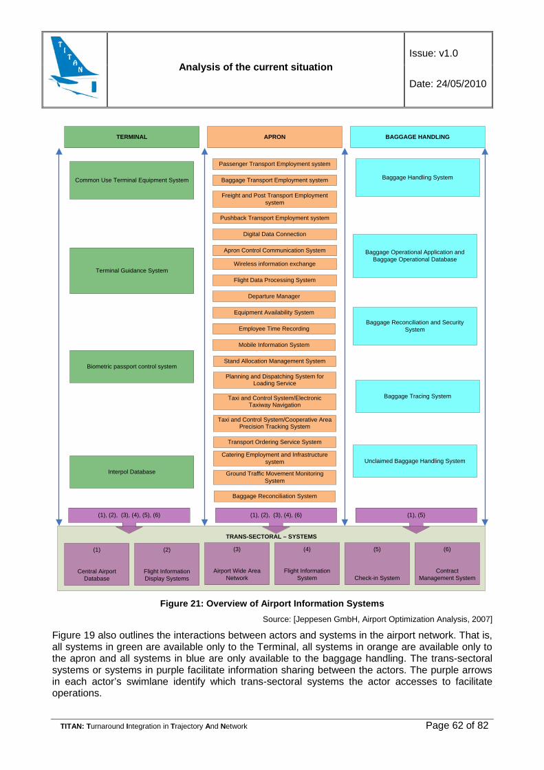
Analysis of the current situation Issue: v1.0
Date: 24/05/2010
TITAN: Turnaround Integration in Trajectory And Network Page 62 of 82
TRANS-SECTORAL – SYSTEMS
(1)
Central Airport Database
(2)
Flight Information Display Systems
(3)
Airport Wide Area Network
(4)
Flight Information System
(5)
Check-in System
(6)
Contract Management System
TERMINAL APRON BAGGAGE HANDLING
Common Use Terminal Equipment System
Terminal Guidance System
Biometric passport control system
Interpol Database
Baggage Handling System
Baggage Operational Application and Baggage Operational Database
Baggage Reconciliation and Security System
Baggage Tracing System
Unclaimed Baggage Handling System
Flight Data Processing System
Departure Manager
Equipment Availability System
Employee Time Recording
Mobile Information System
Stand Allocation Management System
Planning and Dispatching System for Loading Service
Transport Ordering Service System
Catering Employment and Infrastructure system
Baggage Reconciliation System
Ground Traffic Movement Monitoring System
Passenger Transport Employment system
Baggage Transport Employment system
Freight and Post Transport Employment system
Pushback Transport Employment system
Digital Data Connection
Apron Control Communication System
Wireless information exchange
(1), (2), (3), (4), (6)(1), (2), (3), (4), (5), (6)
Taxi and Control System/Electronic Taxiway Navigation
Taxi and Control System/Cooperative Area Precision Tracking System
(1), (5)
Figure 21: Overview of Airport Information Systems
Source: [Jeppesen GmbH, Airport Optimization Analysis, 2007]
Figure 19 also outlines the interactions between actors and systems in the airport network. That is, all systems in green are available only to the Terminal, all systems in orange are available only to the apron and all systems in blue are only available to the baggage handling. The trans-sectoral systems or systems in purple facilitate information sharing between the actors. The purple arrows in each actor’s swimlane identify which trans-sectoral systems the actor accesses to facilitate operations.

Analysis of the current situation Issue: v1.0
Date: 24/05/2010
TITAN: Turnaround Integration in Trajectory And Network Page 63 of 82
In the following sections the Information Systems at an airport are described in further detail, especially the components which are used daily by airport stakeholders.
Airport Trans-sectoral Systems
Trans-sectoral means that the systems cannot be categorized to only one area. They are operated in two or all three defined areas of the airport. Table 22 describes the main systems at a large airport.
No Systems / Databases Functionality
1 Central Airport Database • central database of the airport • provides flight and airport related data
2 Flight Information Display Systems (FIDS)
• informs passenger and external service provider about all relevant flight related data (gate, take-off time, gates etc.)
3 Airport Wide area network • network at an airport • provides connections to the Wide Area
Network (WAN)
4 Flight Information System
• portal for flight information (both for passengers and for internal operating divisions)
• customer-specific filters and screens provide selected, individualized information
5 Check-in System • bundles all passenger related
information, e.g. reservations, re-bookings, irregularities.
6 Contract Management System (CMS)
• supports airlines, external provider etc. with the issue and administration of contracts with the airport operator
Table 22: Systems operated at several areas Source: [Jeppesen GmbH, Airport Optimization Analysis, 2007]
4.2.1.1 Systems Operated at the Terminal
The systems that used for passenger handling in the terminal are presented in this subsection. There are six trans-sectoral systems, which are already described in Table 22, and additionally four systems, which are only operated in this specific area.
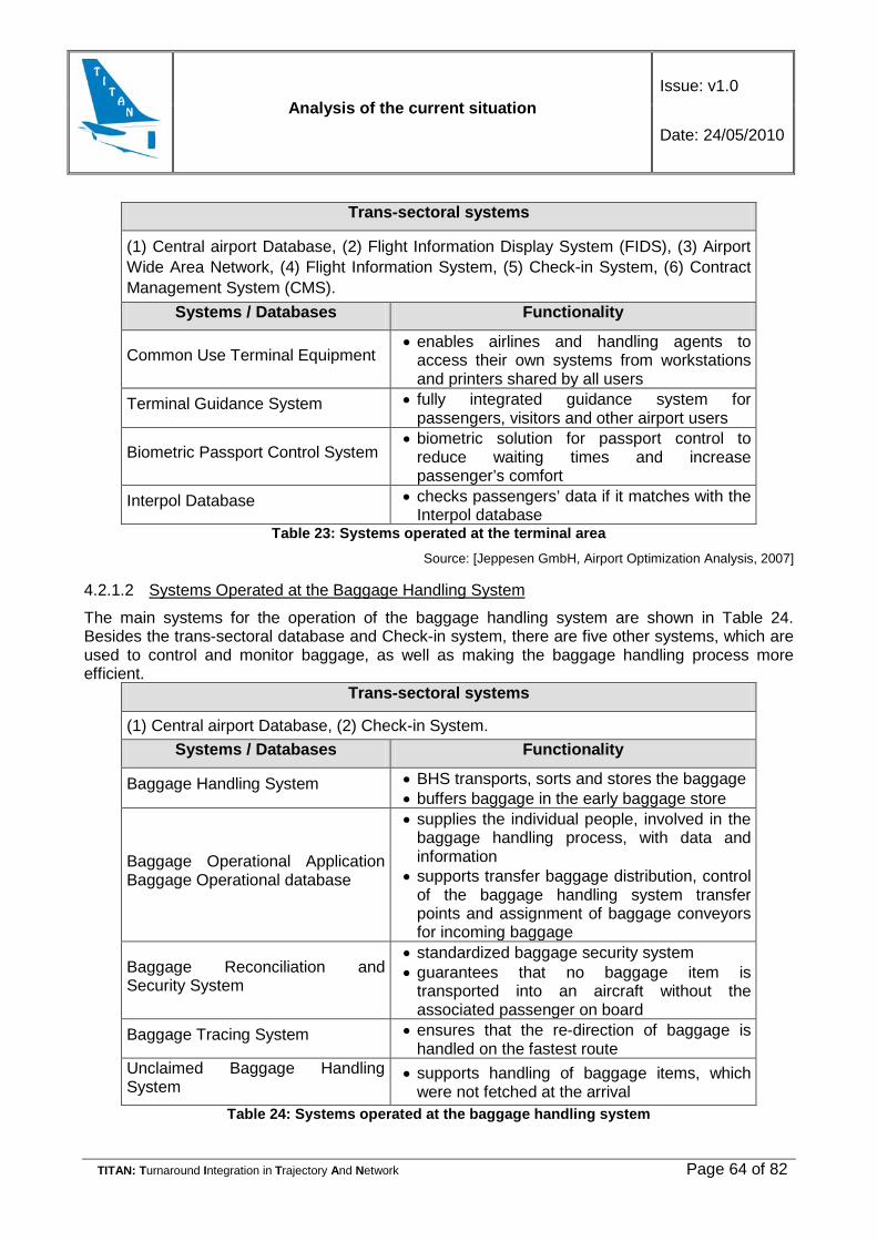
Analysis of the current situation Issue: v1.0
Date: 24/05/2010
TITAN: Turnaround Integration in Trajectory And Network Page 64 of 82
Trans-sectoral systems
(1) Central airport Database, (2) Flight Information Display System (FIDS), (3) Airport Wide Area Network, (4) Flight Information System, (5) Check-in System, (6) Contract Management System (CMS).
Systems / Databases Functionality
Common Use Terminal Equipment • enables airlines and handling agents to
access their own systems from workstations and printers shared by all users
Terminal Guidance System • fully integrated guidance system for passengers, visitors and other airport users
Biometric Passport Control System • biometric solution for passport control to
reduce waiting times and increase passenger’s comfort
Interpol Database • checks passengers’ data if it matches with the Interpol database
Table 23: Systems operated at the terminal area Source: [Jeppesen GmbH, Airport Optimization Analysis, 2007]
4.2.1.2 Systems Operated at the Baggage Handling System
The main systems for the operation of the baggage handling system are shown in Table 24. Besides the trans-sectoral database and Check-in system, there are five other systems, which are used to control and monitor baggage, as well as making the baggage handling process more efficient.
Trans-sectoral systems
(1) Central airport Database, (2) Check-in System. Systems / Databases Functionality
Baggage Handling System • BHS transports, sorts and stores the baggage • buffers baggage in the early baggage store
Baggage Operational Application Baggage Operational database
• supplies the individual people, involved in the baggage handling process, with data and information
• supports transfer baggage distribution, control of the baggage handling system transfer points and assignment of baggage conveyors for incoming baggage
Baggage Reconciliation and Security System
• standardized baggage security system • guarantees that no baggage item is
transported into an aircraft without the associated passenger on board
Baggage Tracing System • ensures that the re-direction of baggage is handled on the fastest route
Unclaimed Baggage Handling System
• supports handling of baggage items, which were not fetched at the arrival
Table 24: Systems operated at the baggage handling system
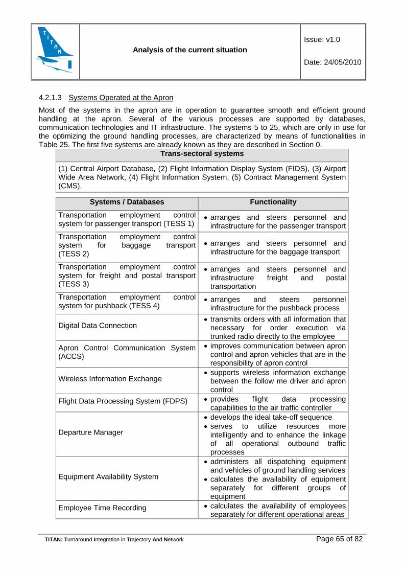
Analysis of the current situation Issue: v1.0
Date: 24/05/2010
TITAN: Turnaround Integration in Trajectory And Network Page 65 of 82
4.2.1.3 Systems Operated at the Apron
Most of the systems in the apron are in operation to guarantee smooth and efficient ground handling at the apron. Several of the various processes are supported by databases, communication technologies and IT infrastructure. The systems 5 to 25, which are only in use for the optimizing the ground handling processes, are characterized by means of functionalities in Table 25. The first five systems are already known as they are described in Section 0.
Trans-sectoral systems
(1) Central Airport Database, (2) Flight Information Display System (FIDS), (3) Airport Wide Area Network, (4) Flight Information System, (5) Contract Management System (CMS).
Systems / Databases Functionality
Transportation employment control system for passenger transport (TESS 1)
• arranges and steers personnel and infrastructure for the passenger transport
Transportation employment control system for baggage transport (TESS 2)
• arranges and steers personnel and infrastructure for the baggage transport
Transportation employment control system for freight and postal transport (TESS 3)
• arranges and steers personnel and infrastructure freight and postal transportation
Transportation employment control system for pushback (TESS 4)
• arranges and steers personnel infrastructure for the pushback process
Digital Data Connection • transmits orders with all information that
necessary for order execution via trunked radio directly to the employee
Apron Control Communication System (ACCS)
• improves communication between apron control and apron vehicles that are in the responsibility of apron control
Wireless Information Exchange • supports wireless information exchange
between the follow me driver and apron control
Flight Data Processing System (FDPS) • provides flight data processing capabilities to the air traffic controller
Departure Manager
• develops the ideal take-off sequence • serves to utilize resources more
intelligently and to enhance the linkage of all operational outbound traffic processes
Equipment Availability System
• administers all dispatching equipment and vehicles of ground handling services
• calculates the availability of equipment separately for different groups of equipment
Employee Time Recording • calculates the availability of employees separately for different operational areas
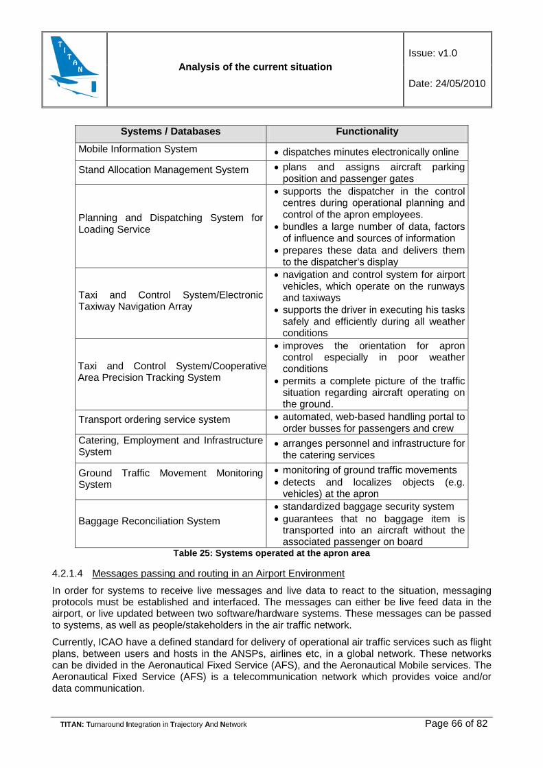
Analysis of the current situation Issue: v1.0
Date: 24/05/2010
TITAN: Turnaround Integration in Trajectory And Network Page 66 of 82
Systems / Databases Functionality
Mobile Information System • dispatches minutes electronically online
Stand Allocation Management System • plans and assigns aircraft parking position and passenger gates
Planning and Dispatching System for Loading Service
• supports the dispatcher in the control centres during operational planning and control of the apron employees.
• bundles a large number of data, factors of influence and sources of information
• prepares these data and delivers them to the dispatcher’s display
Taxi and Control System/Electronic Taxiway Navigation Array
• navigation and control system for airport vehicles, which operate on the runways and taxiways
• supports the driver in executing his tasks safely and efficiently during all weather conditions
Taxi and Control System/Cooperative Area Precision Tracking System
• improves the orientation for apron control especially in poor weather conditions
• permits a complete picture of the traffic situation regarding aircraft operating on the ground.
Transport ordering service system • automated, web-based handling portal to order busses for passengers and crew
Catering, Employment and Infrastructure System
• arranges personnel and infrastructure for the catering services
Ground Traffic Movement Monitoring System
• monitoring of ground traffic movements • detects and localizes objects (e.g.
vehicles) at the apron
Baggage Reconciliation System • standardized baggage security system • guarantees that no baggage item is
transported into an aircraft without the associated passenger on board
Table 25: Systems operated at the apron area
4.2.1.4 Messages passing and routing in an Airport Environment
In order for systems to receive live messages and live data to react to the situation, messaging protocols must be established and interfaced. The messages can either be live feed data in the airport, or live updated between two software/hardware systems. These messages can be passed to systems, as well as people/stakeholders in the air traffic network.
Currently, ICAO have a defined standard for delivery of operational air traffic services such as flight plans, between users and hosts in the ANSPs, airlines etc, in a global network. These networks can be divided in the Aeronautical Fixed Service (AFS), and the Aeronautical Mobile services. The Aeronautical Fixed Service (AFS) is a telecommunication network which provides voice and/or data communication.

Analysis of the current situation Issue: v1.0
Date: 24/05/2010
TITAN: Turnaround Integration in Trajectory And Network Page 67 of 82
Part of its overall operation is based on:
• AFTN (the Aeronautical Fixed Telecommunication Network);
• CIDIN (the Common ICAO Data Interchange Network);
• AMHS (Air Traffic Services (ATS) Message Handling System)
AMHS is the most recently developed and deployed transmission system, and is becoming the standard in most update networks. It is a standard for aeronautical ground-ground communications (e.g. for the transmission of NOTAM, Flight Plans or meteorological data) based on X.400, a standard protocol for exchanging and addressing electronic messages. AFTN and CIDIN are legacy technologies which were designed and built based on available network technologies in the 1970’s and 1980’s. The goal of CIDIN was to replace AFTN technologies; however the CIDIN technologies are now nearing obsolescence. The X.25 equipment and protocols which CIDIN are based on are being phased out. The X.400 communication standards which AMHS is being built on addresses exchanging ATS messages over ATN Internet. The AMHS also provides increased functionality, to support more ATS message exchanges than those in the legacy systems. This includes, for example, the capability to exchange binary data messages or to secure message exchanges by authentication mechanisms. The old AFTN limit of a 1,800 character maximum message length will of course be removed also.
Aircraft Communications Addressing and Reporting Systems (ACARS) is a digital datalink system which facilitates transmission of short messages between aircraft and ground stations via radio or satellite. These messages are used to communicate the status of an aircraft by broadcasting it to the required parties. However it is also a legacy network. Over the next 20 years, ACARS will be superseded by the ATN protocol/s for Air Traffic Control communications and by the Internet Protocol for airline communications.
Some messages shared at an airport are airline specific. Today the airline industry continue to use teletype messages over ARINC, SITA or AFTN networks as a medium for communicating via messages. Type B messages are IATA standard format of message posting based on the status of the aircraft. These messages are related to activities regarding the status of an aircraft. Messages such as Aircraft on the Ground (AOG) and movement (MVT) messages are produced. Systems are available which can manage Type-B messages, and deliver the message by email or some other communication protocol to share updates.
Products in airports exist such as SITATEX, a client-based software application that generates and receives Type B messages, which is the standard format for messaging in the air transport industry. It uses the Internet, IP networks and dial connections to communicate messages and documents between locations. The ability of such systems to filter and share relevant messages to relevant parties is an advantage in airport communications and information sharing.
4.2.1.5 Summary of systems and their usage in the airport environment
The above information systems describe that communication at an airfield can be facilitated by:
1. Computer terminal to Computer terminal communication (via wire);
2. Mobile device communication (via WiFi);
3. Direct Human to Human system interaction (via phone or radio).
The closer operations get to a physical aircraft, the more communication is facilitated by modes 2 and 3. In matters of planning and synchronization which is performed further away from the aircraft, more direct wire communications are executed. Downloading and access of information

Analysis of the current situation Issue: v1.0
Date: 24/05/2010
TITAN: Turnaround Integration in Trajectory And Network Page 68 of 82
from databases is another common task in planning and synchronizing airport apron processes. A single datastore provides data to most of the systems associated with airport. In cases where there is communication between systems, systems will feed data between each other which is then fed back to a stakeholder or control centre. The stakeholder or control centre is then responsible for distributing this information to other parties on a “need to know” basis.
Many of the systems provide a single purpose, and are then integrated to give an entire solution to the airport, and to share the required information to all relevant parties.
4.2.2 Airline Information Systems Airlines are in the situation where their information systems have two major stakeholders. The main stakeholder is the public – the airline’s customers. The second major stakeholder is the internal business, and having information systems which support and optimise the Airline’s business process. The tools used in these two environments are outlined in the following section.
4.2.2.1 Information Systems for Communication with Customers and Increasing business
Airlines need to maintain a strong relationship with their customers to retain their business and quality service. Offering efficient information systems as an interface between the Airline and their customers is one way to do this. This interaction is performed via the Internet, where airlines can offer the following types of services to their customers, from a webpage:
• Viewing Flights and Fare information;
• Flight Booking;
• Online Check-in;
• Access to Airline Schedules and Timetables;
• Flight Status’ of the current flights;
• Management of Booking and access to Services.
Databases are maintained with information about reward flyers, frequent flyers and passengers from here can personalize profiles. This additional information about their passengers can be mined from databases and give trends and information which the airline can use to analyse its market and the trends in its customers’ flight patterns.
4.2.2.2 Information Systems for Planning and Process Optimisation
Airlines often use a suite of Information systems to manage and optimize the following tasks:
• Resource Management;
• Resource Planning;
• Schedule development and Analysis;
• Process optimization and analysis.
Sometimes complex IT systems are used to assist with the above processes. In other cases, it can be as simple as using a Spreadsheet application to perform calculations or view operations in a “Gantt Chart” type view.

Analysis of the current situation Issue: v1.0
Date: 24/05/2010
TITAN: Turnaround Integration in Trajectory And Network Page 69 of 82
Crew management, operations control, aircraft maintenance management and commercial planning are where optimizations are made by airlines, and Information Technology plays a large role in planning and quantifying the benefits of a process or proposal.
Airlines can use tools for strategic planning ahead of the day of operations to investigate:
• Stand allocations and analysis of the productivity associated with certain stands;
• Delays incurred by using alternate stands;
• Fleet mixes for routes.
Analysis of the current situation Issue: v1.0
Date: 24/05/2010
TITAN: Turnaround Integration in Trajectory And Network Page 70 of 82
5. IDENTIFICATION OF POTENTIAL IMPROVEMENTS
5.1 Identify current level of maturity
5.1.1 Research on turnaround processes
5.1.1.1 Scheduling and rescheduling
In 1980s the concepts of scheduling and rescheduling have been developed. These were ISIS and its successor OPIS (Opportunistic Intelligent Scheduler). ISIS was based on baseline scheduling while OPIS was designed to react to disruptions by implementing reactive scheduling. It selects an appropriate method, dependent on the resources and their congestion, changing the originally planned resource allocation or postponing selected operations. Following these concepts, NASA Kennedy Space Centre produced GERRY which included scheduling and rescheduling components of the Ground Processing Scheduling System (GPSS). The system optimizes the original schedule in order to increase the quality of solutions.
In the beginning of the 1990s researchers of the Operations Management Group and Katholieke Universiteit Leuven Herroelen and Leus made the distinction between predictive-reactive and proactive-reactive scheduling. The predictive-reactive strategy is aimed at improving the existing schedule by applying the implications of disruptions. In 1995 Teodorovic and Stojkovic proposed a heuristic model based on dynamic programming to reduce the airline schedule disturbances. A few years later Gu and Chung studied the aircraft gate reassignment issue using a genetic algorithm approach. These kinds of models can provide valuable information but at the same time require quite significant level of simplification of real situations. Discrete event simulation which enables finding solutions to large and complex problems was described by Cheng in 1998. Simulation enables experimenting with different resource and operating policy alternatives without disturbing the actual system. Simulation started to be used on a wider scale in aviation from that point onwards. It was used in planning and designing new airports, analyzing and simulating passenger flow in a terminal, identifying bottlenecks in passenger handling or investigating aircraft departure procedures. The latter was analyzed by Ottman, Ford and Reinhardt in 1999 who developed a simulation model helping to determine taxi times, taxi delays, and ramp delays during changes in flight departure schedules and parking plans. It was also applied to analyze stages involved in an airport expansion and potential changes in the airport property. Recently, progress was made regarding the proactive-reactive scheduling which is based on the assumption that it is robust. In 2007 the researchers Van de Vonder, Demeulemeester and Herroelen classified the predictive-reactive project scheduling procedures. These are the disturbances that can be predicted and incorporated in the schedules. As a consequence, the reactive procedures have to be applied only in few and specific unexpected situations.
5.1.1.2 Disruption Management
Over the years, several studies providing an overview of scheduling and rescheduling approaches, their environment and performance indicators, have been published. Nevertheless, only recently the concept of Disruption Management emerged. The rescheduling concept assumes that the changes are made in the original schedule while the original function remains the same. On the other hand, Disruption Management focuses not only on changes to the original schedule but aims at minimizing the deviations from the original schedule. In case of the turnaround process the aim of Disruption Management is not only to redraft in place and time all the processes that have to be done, but also to minimize the turnaround time and aim at minimizing the plane’s delay. The

Analysis of the current situation Issue: v1.0
Date: 24/05/2010
TITAN: Turnaround Integration in Trajectory And Network Page 71 of 82
Decision Support for Integrated Crew and Aircraft Recovery project (Descartes) was a cooperative project of British Airways, Carmen Systems and the Technical University of Denmark. The main result of the Descartes project is the development of a decision support tool designed to handle all sizes of disruption and to match better the decisions that are made by the Operations Controllers (in terms of time and cost). Descartes added value to the business and enabled provision of solutions that are of similar or better quality. The domains covered by the Disruption management are the air traffic, airline-related scheduling, as well as machine scheduling and production planning.
5.1.1.3 Turnaround time modelling
As the recent studies show, many air traffic delays can be directly attributed to turnaround activities. This area is not extensively analyzed and described in the literature. In the 70s the aircraft turnaround activities were analyzed by Braaksma and Shortreed who used a critical path method. Their work was innovative even though focused only on a single turnaround operation at one gate, and did not take into account the possibility of unusual delays during the turnaround. Many years later, in 1996 an application of discrete-event simulation in modelling and the analysis of aircraft cargo offloading operations at an air-cargo hub was published by Manivannan and Zeimer. The simulation included a base model presenting the cargo offloading operation. The results showed the best configurations for resource planning.
In the year 2000 a study of ground operations at hub airports was carried out by Andersson, Carr, Feron and Hall. The aim of the study was to build an airport congestion prediction capability. Maintenance activities during the turnaround for a commercial aircraft have been investigated from a maintenance worker resource level planning perspective by Gupta, Bazargan & McGrath. The turnaround delays associated with passenger boarding have been analyzed by Landeghem and Beuselinck in 2002 who conducted a simulation analysis investigating different boarding patterns and operating strategies. In the same period Wu and Caves developed a simulation model limited to baggage/cargo flow and passenger/crew flow. It was designed to simulate aircraft rotation in a multiple airport environment. The model does not include other aircraft turnaround activities (such as refuelling, aircraft maintenance, and catering).
The above presented review of the literature provides a general overview on the developments of academics regarding the turnaround processes. It can be concluded that many important steps have been made in the last thirty years that contributed to improvements in the industry.
5.1.2 Industry improvements regarding turnaround times
5.1.2.1 Turnaround time improvements
In the past, the average turnaround time was much longer than presently. There can be found numerous reasons for that. First of all, there was less knowledge about the effectiveness of turnaround processes. Also the dependence of the economic costs and benefits on the turnaround times was not clear. Another reason can be found in different structure of the air fleet and different distribution of flights in space and time. Important change occurred with the development of low cost carriers. As they rely on the maximum possible usage of an aircraft, they decrease the turnaround times to minimum. As a result, passengers waiting for embarkation can often see their plane landing and people disembarking from the previous flight. As many LCC charge additionally for check-in baggage, many passengers take only carry-on baggage with them. Another time consuming process – catering - is also minimized. By setting additional charges on meals and drinks, LCC limit the number of meals and drinks they serve and at the same time, minimize the

Analysis of the current situation Issue: v1.0
Date: 24/05/2010
TITAN: Turnaround Integration in Trajectory And Network Page 72 of 82
time needed for providing the aircraft with food. Often these are the flight attendants who clean the aircraft between the flights and therefore decrease the time needed for the personnel to arrive and perform these services. More and more often various airlines introduce the system first come – first serve. At the gate passengers are often requested to embark in a certain order, for example first passengers with seats numbered from 1 to 30, than 31-60, and so on. Other carriers offer tickets without numbered seats. As a result, passengers are asked to embark the plane in the check-in order. This solution can also decrease the overall turnaround time as passengers will come earlier to make sure they have a seat at the front of the plane or close to their friends and family. Finally, airlines have always been looking for ways to decrease their turnaround time.
5.1.2.2 Financial incentives related to turnaround times
Some airports introduced the landing and take-off charges that are dependent on the turnaround time for passenger aircrafts. Frankfurt Hahn airport can be an example with a criterion of a turnaround time of up to 30 minutes for passenger aircrafts with a maximum take-off weight (MTOW) of over 5,7t. If 90% of turnaround times in a calendar year are completed within 30 minutes, the criterion is met. If this criterion is not met, the airlines are obliged to pay additionally. The turnaround time TRT may exceed 30 minutes, if a change in cockpit and/or cabin crew is needed. This time is not calculated in the turnaround time. The turnaround time is established for all relevant turnaround times of an airline on a monthly basis. The landing and take-off fee is charged accordingly. In the following month of a finished calendar year, the turnaround time is determined again for all turnarounds carried out by the airline taken over the year. The airport operator will charge or give credit for any differences in the airlines’ monthly invoices. The turnaround processes involve many actors and their time differs per airport, airline, aircraft, etc. Due to the developments in research and industry, the average turnaround time has been declining over the years. The example of Frankfurt Hahn airport shows that charges introduced linked to capacity constraints at an airport can influence turnaround times and as a result provide financial incentives to the airlines.
5.1.3 New developments The turnaround processes are constantly changing. Especially nowadays, in the times of natural resources constraints and financial crisis, there is a constant pressure from the airlines to decrease the turnaround times and increase the usage of the aircraft. The academics work more closely with the industry which results in some important developments.
5.1.3.1 Material Management
In 2008 Boeing and SAS Technical Services signed a Contract for Integrated Materials Management Parts Solution. This contract will enable improved spare parts availability, increased service level to the mechanic and improved cash benefits for STS with a simplified point of management. Under this program, Boeing will handle all invoicing and provide increased competitive parts pricing through Boeing's buying power. According to Gustav Johansson, the director of STS Material Management, "STS sees an advantage when joining the IMM program and the goal at STS is to gradually increase part numbers so more parts are available to customers for a quick turnaround." It is an important step in avoiding lack of material as well as overstocking.

Analysis of the current situation Issue: v1.0
Date: 24/05/2010
TITAN: Turnaround Integration in Trajectory And Network Page 73 of 82
5.1.3.2 Radio-Frequency Identification
A new project by the Cambridge University has potential in decreasing airport delays by streamlining the chain of operations that prepares an aircraft for its next flight. It is projected that the project could reduce the aircraft turnaround delays by a quarter. The new automated identification technology is being tested. The feed information gathered via electronic tags goes back to computers, to examine how it could be used to speed up the airport operations by making equipment and processes more visible. This could result in important improvements at airports around the world. Earlier research carried out by the University's Institute for Manufacturing showed that the use of Auto-ID Technology and better data-sharing between airlines, ground-handlers, fuellers and caterers could cut delays in aircraft turnaround times by 25 per cent. In the past, many types of Auto-ID technology have been tested but this is the first attempt of using the new technology on an airport-wide basis. Researchers plan to test the use of Radio-Frequency Identification (RFID) tags to provide visibility of different assets used in airport operations. Auto-ID technology has potential in eliminating time-consuming tasks such as counting passengers or establishing that every piece of luggage is on board. IATA has examined the use of RFID in baggage handling, catering, cargo, parts and aircraft turnaround. All of these areas can benefit from the application of RFID to enable more event-driven and proactive processes. The benefit in each area, however, varies depending on the airline or airport in question. For example, RFID can be used in baggage handling to reduce no-read rates and to monitor transfer of responsibility at originating and departing airports. There are, however, cases where introduction of RFID would not make sense. An example can be airports or areas where a highly-developed infrastructure that incorporates the use of a DCV (Destination Coded Vehicle) already exists, where rate of baggage mishandling is less than 0,001, etc.
5.1.4 Summary of the improvements
As descried above, there have been important changes in the turnaround processes and turnaround time in the past years. This relates to the research done by academics as well as the industry itself. The analysis of these developments and improvements made as well as the scope of the current studies show that there is still room for improvement. This can be found in the continuous changes in the structure of the industry, operational changes regarding separate processes and last but not least the communication and information exchange between various parties involved in the turnaround process.
5.1.4.1 Efficiency of LCCs
Recently, LCC started to expend on their non-core routes. Until recently, only traditional operators have been flying on long-haul routes. Since LCC started to operate on long haul routes, this can have important effects on the average turnaround times on airports. AirChina is open with its ambitions on becoming one of the largest airlines in the world and their development is oriented on adopting many solutions used by LCCs. Their plans are to decrease average turnaround times to only 25 minutes.
5.1.4.2 Operations
There are many potential improvements possible at various stages of turnaround process. One of them is embarkation and disembarkation of passengers. There are many simple boarding solutions

Analysis of the current situation Issue: v1.0
Date: 24/05/2010
TITAN: Turnaround Integration in Trajectory And Network Page 74 of 82
that should be tested and adopted not only by LCC but by traditional operators as well. Some ideas include parking the aircraft backwards for embarkation and letting the passengers with seats at the beginning of the plane to enter first, using two doors for embarkation and disembarkation, starting embarkation of business Class passengers almost at the same moment as disembarkation of the passengers from the previous flights is taking place, or embarkation of disabled passengers after all other passengers are already in the plane, etc. There are many possible solutions which could be adopted by various airlines.
5.1.4.3 Information and communication
Finally, relatively obvious but extremely important issue is information sharing. It is not done in the most efficient way nowadays. The companies carrying out various tasks within the turnaround process don't always share information and if they do, it is often not done on a satisfactory level. A breakdown somewhere along the line can cause a huge delay due to lack of information or miscommunication.
In this respect the TITAN concept could be a major improvement in the turnaround process. It addresses the market changes, the optimization of turnaround processes as well as communication and information sharing between the actors involved in the process. The decision support tool designed in TITAN could significantly contribute to the turnaround process optimization.
5.2 Best practices in Europe and USA. Benefits experienced in European CDM projects
5.2.1 Historical perspective The concept of Collaborative Decision Making (CDM) was originally defined in the United States by a group of airlines, led by US Airways, in response to what the airlines perceived as inadequate co-operation between airports, the FAA and the airlines themselves. They formed the so called CDM Group, members of which visited several airports with traffic flow problems and analysed the reasons. Significantly, they discovered that in many cases the reasons were in fact quite trivial. In one case, a missing telephone connection between the FAA tower and the Delta ramp controller was found to be at the root of major departure delays; in another case the “secret” nature of cancelled flights was found to be the cause of unused slots at an otherwise seriously congested airport.
The CDM Group in its original reports had actually established three of the most basic rules of CDM which remain valid to this day even if, unfortunately, in some cases they are being ignored. The three rules are:
1. Most problems have simple causes with simple solutions;
2. Better information sharing eliminates a very large proportion of the problems;
3. CDM can only be successful if trust is established between the partners as the first step.
Although the CDM Group did at first address problems at airports (Atlanta and Philadelphia) when the FAA embraced the concept, they focused on applying it in the en-route environment. This was a natural consequence of the US scene where capacity constraints were present en-route while

Analysis of the current situation Issue: v1.0
Date: 24/05/2010
TITAN: Turnaround Integration in Trajectory And Network Page 75 of 82
airports were almost all free flow at the time. Nevertheless, US airports got involved in CDM early as a result of the FAA’s ground-delay concept. The value of information sharing was shown right from the start. Just by being better informed, airlines were able to respond to the restrictions in a much more efficient manner. The initiative in the early 1990s called FAA/Airline Data Exchange (FADE), supported among others by Northwest Airlines, can be seen as the direct forerunner of what evolved into the US CDM project of to-day.
The CDM concept was brought to Europe by experts of IATA and at first it was treated as a research topic and as such, assigned to the EUROCONTROL Experimental Centre. Several years passed and the concept was stuck on the research agenda while the need for better decision making grew every day. At the time, also in Europe most of the delay problems had their origins in the en-route environment and of course the power of CDM could have brought the same level of relief as it did in the US if only States had gotten together and implemented CDM. But this did not happen in spite of repeated please by the airspace users.
The lack of progress did not go unnoticed by EUROCONTROL and they came up with a new idea. Even if it was proving very difficult to get European States to embrace CDM in the en-route context, the more independent and business minded airports, with their more or less closed systems and multiplicity of partners, might prove more receptive to improved decision making and hence introducing CDM on the airport level might prove to be actually feasible. This is how Airport CDM (A-CDM) was borne.
In recent years of course airports in Europe have become a major source of delay and hence A-CDM was proven to be a good idea in more sense than one. But all development projects must keep in mind that A-CDM is not special at all, it is simply a pragmatic sub-set of CDM implementation forced by the initial failure of getting CDM on-board in the en-route context.
Not that A-CDM was an immediate hit. Although many airports created CDM teams, built systems and even booked some initial results, full, across the board exploitation of CDM remains the exception rather than the rule.
An important, relatively recent development of course is the realisation that individual airports forming “CDM islands” can only achieve limited benefits if the air traffic management network of which they are a part is not fully involved. Bringing the Central Flow Management Unit (CFMU) into the CDM picture was a major step in CDM implementation in Europe and the first one in realising what one may call “network CDM”.
Needless to say, CDM is an important element in the operational concept of both the European SESAR program and NextGen in the US. Under these initiatives, all decisions will be required to be collaborative to the maximum extent possible and hence the idea of CDM will be influencing the very core of air traffic management practice at every level.
5.2.2 CDM applications in the USA and Europe EUROCONTROL and the FAA actively cooperate on many aspects of CDM. There are several European ideas and procedures that are being considered for inclusion in the US CDM projects, among them the better utilisation of Target Off-Block Time (TOBT) and next day planning. The US CDM project has several sub-teams and they manage a range of CDM sub-projects, most of which are specific to the integrated US air traffic management environment. It is important to note that the US CDM projects can benefit from a lot of information sharing functionality already available in the FAA’s systems. These capabilities are being delivered by the US System Wide Information Management (SWIM) program which has as its main task the data level integration of the legacy systems as well as the new system elements being implemented.

Analysis of the current situation Issue: v1.0
Date: 24/05/2010
TITAN: Turnaround Integration in Trajectory And Network Page 76 of 82
A lot of the US CDM activity is dealing with items that in Europe would fall under the purview of the CFMU. Examples are the Integrated Collaborative Rerouting (ICR), Airspace Flow Program (AFP) or the Unified Ground Delay Program (UDP). Others, like the integration of the Traffic Management Advisor (TMA) and the Flight Schedule Monitor (FSM) or the Control by Time of Arrival (CbTA) concept are more on the control centre level.
The US CDM scene is also influenced to a large degree by the initiatives taken by some airlines to improve their own operations. This is a US peculiarity mainly because there is no comparable operational density anywhere in Europe. The Surface Management Systems (SMS) used by UPS in Louisville and by FedEx in Memphis hold a lot of important lessons that can be utilised also at other airports.
CDM in the USA can be seen as encompassing the whole operation and is not split into clearly identifiable elements like airport CDM and network CDM. This is not surprising considering that creating A-CDM in Europe was an artificial division to begin with.
In Europe, CDM is currently instantiated in the form of clearly defined concept elements which are in fact applications that can be realised in software also. They cover areas where a shortcoming had been identified and are meant to directly address those shortcomings. In this way, there is CDM Information Sharing (the basis for everything else), Variable Taxi Time Calculation but also Collaborative Flight Data Update which is in fact a network CDM elements bringing the CFMU into the picture.
Unfortunately, information sharing in Europe is still in its infancy and the only real islands of SWIM-like activity are the airports even if the information sharing practiced there is local and a far cry from the flexible information sharing envisaged by the SWIM concept.
Nevertheless, airport level information sharing has shown conclusively the power of shared information to improve decisions across the board.
Needless to say, the CFMU has several tools used to establish network demand and capacity and to influence both. They do interact with both the users and the providers but their activity is not fully recognised as part of the CDM concept. This should change however as the CFMU moves progressively from a prescriptive to collaborative approach to flow management.
5.2.3 CDM application benefits In 2007-2008, EUROCONTROL had commissioned the production of CDM CBAs for Barcelona, Zurich, Brussels and Munich. At the time, also a generic CBA was produced, taking a typical EUROPEAN airport as the baseline. In 2008, a CDM CBA was also ordered for Prague.
Originally it was the intention to show the benefits of CDM in general but also the specific benefits attributable to the different CDM applications, like information sharing, variable taxi time calculation and so on. This was meant to enable planners to set implementation priorities and find the best possible combination of applications for any given airport.
At that time there was no airport where all the applications had been implemented and so some of the work had to be undertaken using projections and well reasoned assumptions based on interviews with operational experts.
The conclusions were predictable and not at all surprising as they lined up perfectly with the most basic tenets of the CDM concept. In excess of 90 % of the benefits attributable to CDM were in fact generated by information sharing. Other applications added only small, incremental improvements and the order of implementation was also of little impact on the actual benefit picture.

Analysis of the current situation Issue: v1.0
Date: 24/05/2010
TITAN: Turnaround Integration in Trajectory And Network Page 77 of 82
It was therefore not possible to really quantify the benefits of applications, or combinations of applications, beyond information sharing as the additional improvements were well within the error range of the calculations.
Although EUROCONTROL has started to promote a more prescriptive approach to CDM in recent years specifying the implementation order of CDM applications, the fundamental benefit balance of those applications has not changed.
A new feature of CDM of course is the network version where several airports start to collaborate with each other and the CFMU using information sharing and the other applications. This kind of network CDM forms the basis of the SESAR concept of operations also.
In this context it must be mentioned that information sharing as defined for CDM is in fact an early instantiation of the System Wide Information Management (SWIM) concept and at some point SWIM will overtake this aspect of CDM. The benefits will not diminish since support for decision making and the current and future CDM applications will of course continue.
5.2.4 The scope of CDM Because in Europe only airport CDM has made significant progress so far, the best indicator for the scope of CDM as currently practiced is the “milestone approach” CDM application. In this application, the milestones are selected along the timeline representing an aircraft’s progress through the ATM network. Although the milestones are often depicted in a linear manner, they may in fact belong to processes concerned with the flight that run parallel with each other. Some of the processes may also be only indirectly related to the main timeline.
Studying the milestones defined for A-CDM as it currently known it reveals that the CDM scope represented by them is concerned exclusively with the air-side operations of the airport and even there, the scope is restricted to services/processes in the close surrounding of the aircraft concerned. This is perhaps not surprising since analysis of a wider surrounding and especially the land-side operations would probably have been too complex in the initial phases of the European CDM projects.
It is also evident that the turnaround phase of flight is included in the current scope. An aircraft’s trajectory, while it is on blocks at the gate or at a remote stand is in a peculiar status. One may say it is “idling” with only its time dimension evolving, the spatial dimensions not. However, the trajectory continues to consume resources and numerous milestones may be defined to track its evolution in time.
If the CDM scope is kept relatively narrow (air-side only, close in to the aircraft only), the resulting milestones will not capture several important factors which in fact have a direct influence on the idling trajectory. Consider the following. While the aircraft is in the air or taxiing to its stand, its current trajectory is not affected at all by land-side processes, overlong security queues or missing baggage. Once the aircraft is at the gate, processes not currently considered by CDM will suddenly have a direct influence on the idling trajectory, changing its evolution through time. The earlier these influences are known and the better their visibility, the more predictable the trajectory will become and hence the higher the benefits will be.
Most of the processes involved in the turnaround have been studied in the past and while there is still scope for their optimisation, the possibilities for further gains are limited. What have not been studied are the hitherto invisible processes and influences that fall outside the current CDM scope. Most experts agree that very real additional benefits can be generated by looking at the turnaround with a scope that is wider than what is currently the norm.
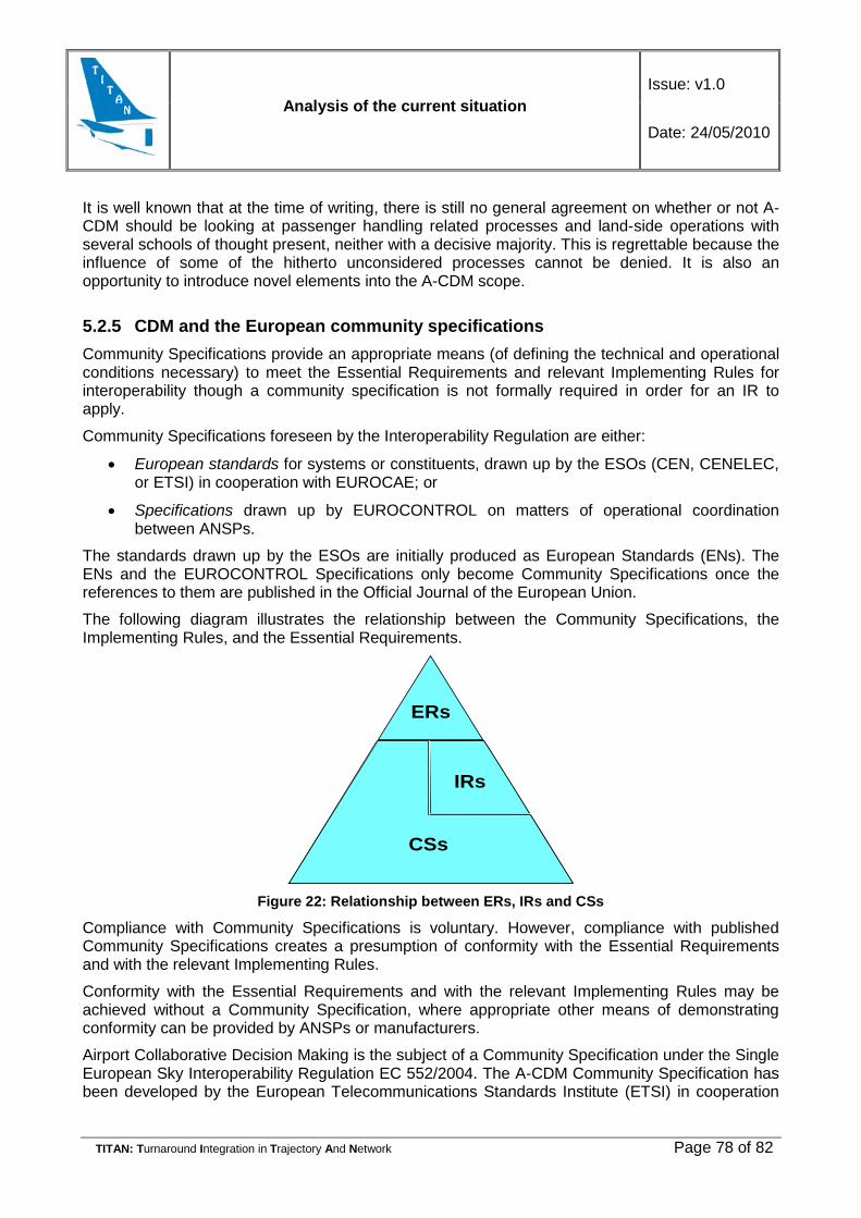
Analysis of the current situation Issue: v1.0
Date: 24/05/2010
TITAN: Turnaround Integration in Trajectory And Network Page 78 of 82
It is well known that at the time of writing, there is still no general agreement on whether or not A-CDM should be looking at passenger handling related processes and land-side operations with several schools of thought present, neither with a decisive majority. This is regrettable because the influence of some of the hitherto unconsidered processes cannot be denied. It is also an opportunity to introduce novel elements into the A-CDM scope.
5.2.5 CDM and the European community specifications Community Specifications provide an appropriate means (of defining the technical and operational conditions necessary) to meet the Essential Requirements and relevant Implementing Rules for interoperability though a community specification is not formally required in order for an IR to apply.
Community Specifications foreseen by the Interoperability Regulation are either:
• European standards for systems or constituents, drawn up by the ESOs (CEN, CENELEC, or ETSI) in cooperation with EUROCAE; or
• Specifications drawn up by EUROCONTROL on matters of operational coordination between ANSPs.
The standards drawn up by the ESOs are initially produced as European Standards (ENs). The ENs and the EUROCONTROL Specifications only become Community Specifications once the references to them are published in the Official Journal of the European Union.
The following diagram illustrates the relationship between the Community Specifications, the Implementing Rules, and the Essential Requirements.
ERs
CSs
IRs
Figure 22: Relationship between ERs, IRs and CSs
Compliance with Community Specifications is voluntary. However, compliance with published Community Specifications creates a presumption of conformity with the Essential Requirements and with the relevant Implementing Rules.
Conformity with the Essential Requirements and with the relevant Implementing Rules may be achieved without a Community Specification, where appropriate other means of demonstrating conformity can be provided by ANSPs or manufacturers.
Airport Collaborative Decision Making is the subject of a Community Specification under the Single European Sky Interoperability Regulation EC 552/2004. The A-CDM Community Specification has been developed by the European Telecommunications Standards Institute (ETSI) in cooperation

Analysis of the current situation Issue: v1.0
Date: 24/05/2010
TITAN: Turnaround Integration in Trajectory And Network Page 79 of 82
with EUROCAE to guide compliance with the Essential Requirements of the Single European Sky Interoperability Regulation and as applicable with the implementing rules in the same regulation.
The end of the public enquiry for the CS was 17 December 2009 and the planned date of publication in the Official Journal of the EU is 27 September 2010.
Although every requirement in the CS is referenced to EUROCONTROL and EUROCAE documents (which were in turn developed with the full participation of European CDM experts), the CS has raised some concerns, mainly by certain airports.
While the need to standardise certain elements of CDM is not in question, the rather rigid rule making seen in the CS has raised fears about how necessary changes will be handled on the one hand and how the nature of CDM would change as a result of what some see as too extensive regulation. This is the case even though compliance with Community Specifications is voluntary. However, since compliance with published Community Specifications creates a presumption of conformity with the Essential Requirements and with the relevant Implementing Rules, the fear exists that there will be too much pressure to comply regardless of how financially sound this may actually be.
A CS can be changed if necessary although there is a procedural overhead. Updates and amendments to a CS are handled by the working structure established for the corresponding field and in accordance with the requirements of the change or amendment. Once a change or amendment has been agreed, it has to be adopted by the Single Sky Committee. Thereafter it takes 3-6 weeks before the change or amendment is published in the Official Journal of the EU. The cause for concern is obviously the time that may be required before the material is submitted to the SSC.
This regulation based approach to CDM is one of the major institutional differences between Europe and the US. In the latter CDM remains a voluntary, collaborative process seen by many as more in line with the original CDM concept. At the time of writing it is not yet clear which approach will prove more effective in the end.
5.2.6 CDM at European airports According to the European CDM web-site, 30 European airports have a CDM project running. Their maturity is very diverse and ranges from early plans through project definition activities to full fledged A-CDM, meeting almost all of the EUROCONTROL functional requirements.
While it was possible to develop a positive cost-benefit analysis for all the planned or actual projects, the most convincing information is available from Munich, the only airport so far with a truly advanced, complex and operational CDM set-up based on the EUROCONTROL A-CDM requirements and which has been in operation without interruption since 7 June 2007. It is interesting to note that even Munich has not followed the original functional requirements to the letter. They have made a few minor changes where those appeared necessary and as such have collected important insights into where the requirements may need to be changed or made more flexible to maximise the benefits for a given local environment without adversely effecting interoperability.
Munich had a very comprehensive set of targets and the results for 2008 (the most recent full year for which data were available at the time of writing) show that basically all targets were met or exceeded. This represents a net overall improvement in the operation of Munich airport as seen from the airspace user perspective. The Munich report notes also that the improved data exchange

Analysis of the current situation Issue: v1.0
Date: 24/05/2010
TITAN: Turnaround Integration in Trajectory And Network Page 80 of 82
with the CFMU that had been undertaken by several airports resulted in a reduction of delays, clearly showing the network benefits of CDM.
The Munich CDM operation does have as one of its targeted benefits optimised turnaround times and the more efficient use of airline/handling agent resources, however, it does not have specific focus on turnaround as such. The scope of CDM in Munich has also been kept to within the traditional limits.
It is not unreasonable to conclude that Munich has pushed the A-CDM benefits close to their maximum potential using the traditional scenarios. This is exactly the situation in which TITAN with its novel look at turnaround optimization can add significant new value.
Analysis of the current situation Issue: v1.0
Date: 24/05/2010
TITAN: Turnaround Integration in Trajectory And Network Page 81 of 82
6. CONCLUSIONS In 2006, turnaround delays constituted 79% of primary delays (according to the Performance Review Report covering the calendar year 2006 – PRR 2006).
Turnaround delays were therefore at the origin of approximately 4/5 of late departures in European airports. But due to the fact that turnaround delays were beyond the scope of this report (the focus being on ATM performance), they had not been analysed and the report just stated that local turnaround delays were caused by airlines (tight scheduling, technical, boarding, etc.), airports (equipment, security, etc.) or other parties such as ground handlers.
It can be observed, however, that the situation in the field of communications has not improved significantly. The stakeholders involved in the turnaround process use their own systems and act in a fragmented way. The airlines have difficulties in collecting and processing information that could help them to make the right decisions during the process. This is the result of historical progress of the process. Many different companies provide services for the same flight and in order to cope with the situation, they have developed their own procedures and systems used to monitor and manage the process.

Analysis of the current situation Issue: v1.0
Date: 24/05/2010
TITAN: Turnaround Integration in Trajectory And Network Page 82 of 82
7. ANNEX 1
Figure 23: Wet pavement
[It is recommended to print it in A3]