tire force and moment properties for … force and... · tire force and moment properties for...
TRANSCRIPT

TIRE FORCE AND MOMENT PROPERTIES FOR COMBINED SLIP CONDITIONS
CONSIDERING CAMBER EFFECT
Nan Xu, Konghui Guo
ASCL State Key Lab, Jilin University
Changchun Jilin, China
April 20-21, 2015
Introduction
Tire axis system and slip ratios
Key factors for developing the analytical tire model
Analytical tire forces and moments model
Simulation analysis and experiment validation
Conclusions
Outline
2

Tire mechanics characteristics under combined cornering/braking and camber situations have significant effects on the vehicle directional control.
The analytical models, which usually include carcass model with elastic tread elements, establish the relationship between tire structure parameters and tire behaviors.
Some key factors are considered in the model of this paper: arbitrary pressure distribution; translational, bending and twisting compliance of the carcass; effective carcass camber, dynamic friction coefficient; anisotropic stiffness properties and tire width.
Combined longitudinal slip, lateral slip and camber.
The analytical model in this paper is valuable for understanding tire properties and developing the semi-empirical models.
Introduction
3

Tire axis system and slip ratios
Fx
Zt
Yt
Xt
Tire revolution
axis Wheel traveling
direction
Fy
My
Mz
Fz
Mx
Tire revolution
direction
V
Ot
cossx ex
r e
V V RS
V R
Unified definition for slip ratios:
Sliding speed /updating speed
sinsy
y
r e
V VS
V R
4

Arbitrary pressure distribution
Unified 3 parameter expression of CPD: for diff
tire structures, loads, inflations & resistances
Key factors for developing the
analytical tire model
-1.0 -0.5 0.0 0.5 1.00.0
0.2
0.4
0.6
0.8
1.0
1.2
1.4
n=1
n=2
n=3
-1.0 -0.5 0.0 0.5 1.00.0
0.2
0.4
0.6
0.8
1.0
1.2
1.4
=0.5
=1
=2
η(u
)
Relative longitudinal coordinate u
=1
n=2
Relative longitudinal coordinate u
η(u
)
2 1 4 1
2 4 1
n nA
n n
3 2 3 4 3 4 1
2 1 4 1 4 3 3
n n nB
n n n a
uBuuAu nn 111)( 22
5
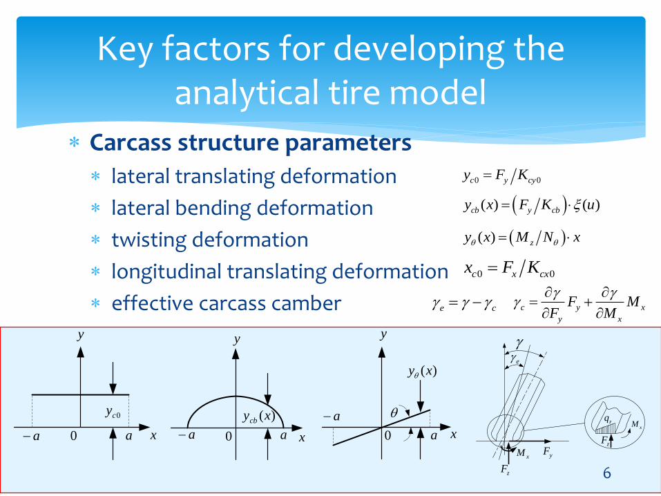
Carcass structure parameters
lateral translating deformation
lateral bending deformation
twisting deformation
longitudinal translating deformation
effective carcass camber
Key factors for developing the analytical tire model
0 0c y cyy F K
( ) ( )cb y cby x F K u
( ) zy x M N x
0 0c x cxx F K
6
0cy
x
y
a a0
)(xycb
x
y
a a0
x
y
a
a0
)(xy
zF
xM
xM
zF
zq
e
yF
e c c y x
y x
F MF M

Dynamic friction coefficient
Key factors for developing the analytical tire model
2 2exp log exps sd s m s h
sm sm
V VN
V V
vs
d
0
s
vsm
m h : describe the variation tendency
where, N(usually N=0.8) is a factor to make the friction coefficient increase slightly around the origin.
7
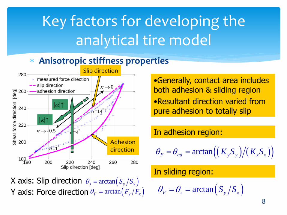
Anisotropic stiffness properties
Key factors for developing the analytical tire model
F ad
F ad 180 200 220 240 260 280
180
200
220
240
260
280
Slip direction [deg]
Sh
ea
r fo
rce
dire
ctio
n
[de
g]
=14
=1
=4
measured force direction
slip direction
adhesion direction
.50-
0
180 200 220 240 260 280180
200
220
240
260
280
Slip direction [deg]
Sh
ea
r fo
rce
dire
ctio
n
[de
g]
=14
=1
=4
measured force direction
slip direction
adhesion direction
.50-
0
In sliding region:
In adhesion region:
X axis: Slip direction arctans y xS S
Y axis: Force direction arctanF y xF F
•Generally, contact area includes both adhesion & sliding region
•Resultant direction varied from pure adhesion to totally slip
arctanF ad y y x xK S K S
arctanF s y xS S
Adhesion direction
Slip direction
||↑
||↑
8

Deformation of carcass and tread element under combined slip condition
Analytical tire forces and moments model
9
O
X
Y
V
o
x
y
xc0
yc0 - ycr
α
θa-aA
D
Pt
Vtcosα
VrtΔx
Δy
x
Pc
deflected carcass due to camber
C
B
wheel plane
belt
contact line wheel spin axis
tread element
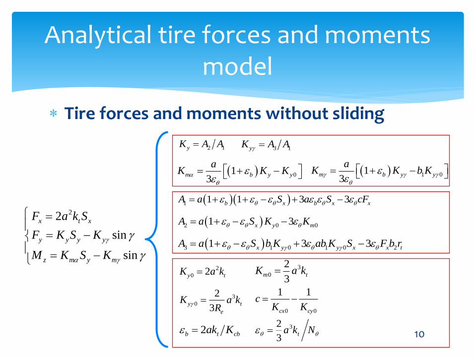
Tire forces and moments without sliding
Analytical tire forces and moments model
10
22
sin
sin
x t x
y y y y
z m y m
F a k S
F K S K
M K S K
2 1yK A A3 1yK A A
013
m b y y
aK K K
1 013
m b y y
aK K b K
1 1 1 3 3b x b x xA a S a S cF
2 0 01 3x y mA a S K K
3 1 0 1 0 21 3 3x y y x x tA a S b K ab K S F b r
2
0 2y tK a k3
0
2
3m tK a k
3
0
2
3y t
e
K a kR
0 0
1 1
cx cy
cK K
2b t cbak K 32
3ta k N

Tire forces and moments in general case with sliding region
Analytical tire forces and moments model
11
1 9 9 4
2 2 1 2 6
4 2
3 1 10 11 3 5 1 2
4 1 5 7
11
1
2 2
31 ,
x z sx
x x z sx x
cb
tx z sx x t
e e
P B B S B F aN
P B B S B S a B F cFK
a k aP b B B S B B F b F b r
R R
P B P Ba
1 0 2 1 3 0
4 1 5 2 6
2
3 2 3
7 8 9
22 4 3 2
10 11
1 1 1, ,
2 2 2
1 1 1, ,
2 2 2
1 1 1, 2 3 , 1 3 2
4 4 4
1 1 1 1, 1
4 4 3 2
b c b c c
c c D c
c
c c c c
c c c cc
B D u B D u B m u
B m u B m u B m u
uB B u u B u u
u u u uB B u
7 3
1 7 0 5 9 0 1 8 1 0 5 3 1 3 5 4
2 5 1 4
2 7 0 4 9 0 2 8 1 0 4 3 2 3 4 4
2 5 1 4
sin
sin
x x x z sx
y m y y z sy
y
y m y y z sy
z
F B K S B F
PB K P B K S PB b K P P PB P B a FF
P P PP
P B K P B K S P B b K P P P B P B a FM
P P PP
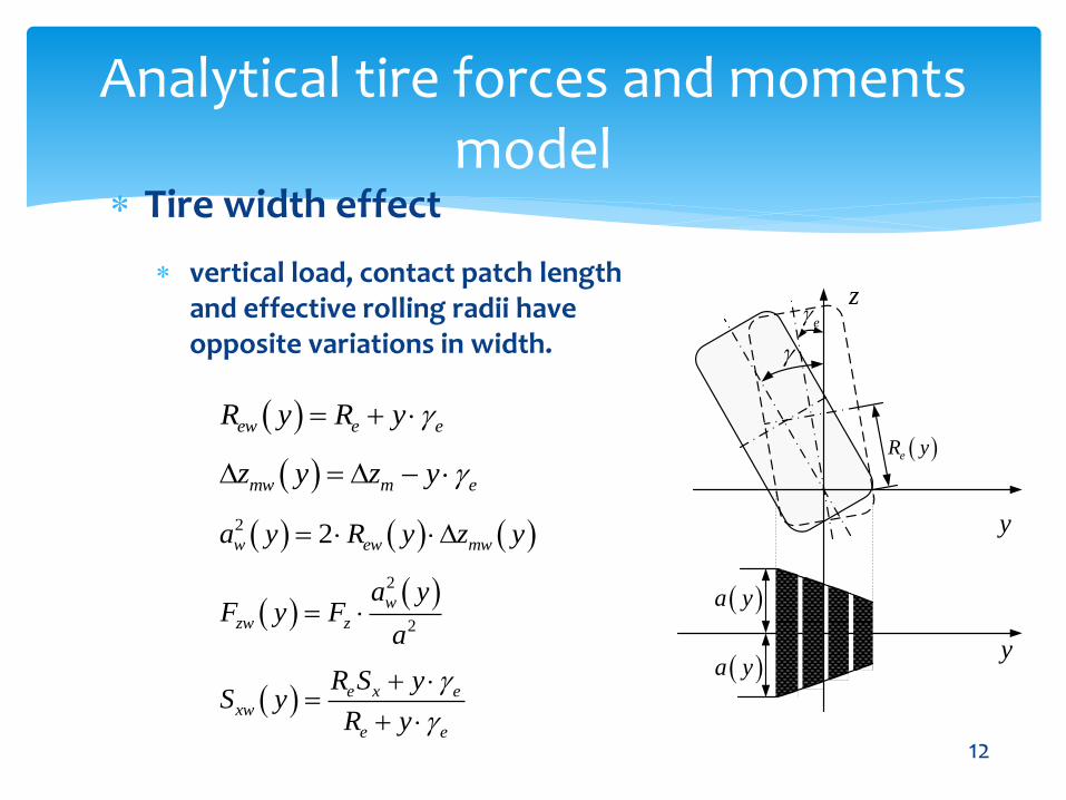
Tire width effect
Analytical tire forces and moments model
12
y
z
eR y
y a y
a y
e
vertical load, contact patch length and effective rolling radii have opposite variations in width.
e x exw
e e
R S yS y
R y
ew e eR y R y
mw m ez y z y
2 2w ew mwa y R y z y
2
2
w
zw z
a yF y F
a

0 0.2 0.4 0.6 0.8 13
4
5
6
7
8x 10
4
Corn
ering s
tiff
ness K
y [
N/r
ad]
Bending characteristic ratio b [-]
=0
cornering stiffness
Effect of carcass compliance on tire cornering stiffness
Simulation analysis and experiment validation
1 1 1 3 3b x b x xA a S a S cF
2 0 01 3x y mA a S K K
2 1yK A A
0
1
1 1y y
b
K K
0xS
bending characteristic ratio εb
twisting characteristic ratio εθ
The cornering stiffness will decrease
with the increase of εb or εθ
13

Cornering stiffness under combined slip condition
Simulation analysis and experiment validation
1 1 1
1 1 3 3
y x b
ypure b x b x x
K S
K S S a cF
-0.05 0 0.050.9
0.95
1
1.05
1.1
1.15
No
rma
lize
d c
orn
ering
stiff
ne
ss [
-]
Longitudinal slip ratio [-]
cornering stiffness will increase when tire has a slight braking. 14

Effect of carcass compliance on aligning moment under combined slip condition
Simulation analysis and experiment validation
0 0
1 1
cx cy
cK K
translating compliance coefficient:
-3000 -2000 -1000 0 1000 2000 3000-50
0
50
Alig
nin
g m
om
en
t M
z [
Nm
]
Longitudinal force Fx [N]
=2
Fz=3000N
c = 0
c = -5×10⁻⁶
c = -10×10-6
c = -15×10-6
15
180 200 220 240 260 280 300 320 340 360180
200
220
240
260
280
300
320
340
360R
esultant
forc
e d
irection [
deg]
Slip direction [deg]
=1
2
=1
2
4
4
braking
driving
adhesion direction
slip direction
resultant force direction
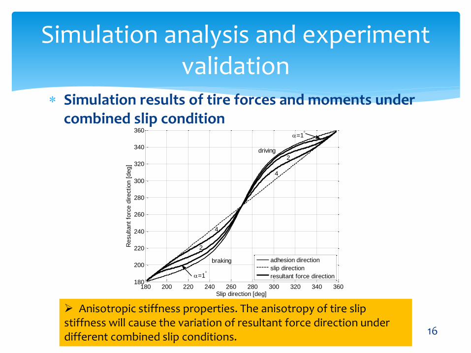
Simulation results of tire forces and moments under combined slip condition
Simulation analysis and experiment validation
Anisotropic stiffness properties. The anisotropy of tire slip stiffness will cause the variation of resultant force direction under different combined slip conditions.
16
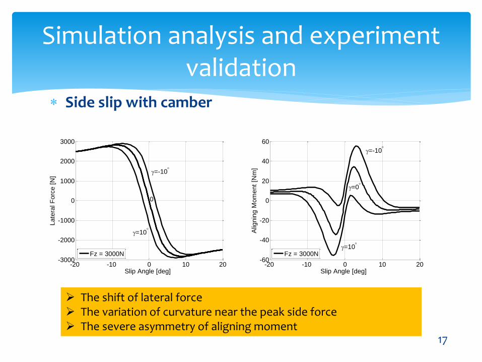
Side slip with camber
Simulation analysis and experiment validation
The shift of lateral force The variation of curvature near the peak side force The severe asymmetry of aligning moment
17
-20 -10 0 10 20-3000
-2000
-1000
0
1000
2000
3000
Late
ral F
orc
e [
N]
Slip Angle [deg]
=-10
=10
0
Fz = 3000N
-20 -10 0 10 20-60
-40
-20
0
20
40
60
Alig
nin
g M
om
ent
[Nm
]
Slip Angle [deg]
=-10
=0
=10
Fz = 3000N

Longitudinal slip with camber
Simulation analysis and experiment validation
Side force has an extreme variation when applying braking/driving force, and Fy even changes its sign in the driving half of the diagram. The aligning torque, aroused by longitudinal force and shifted point of action due to camber, will generate an additional distortion of the carcass which results in an effective slip angle. 18
-1 -0.5 0 0.5 1-1000
-500
0
500
1000
Late
ral F
orc
e [
N]
Longitudinal Slip Ratio [-]
-2
-5
=-10
=10
Fz = 3000N
-1 -0.5 0 0.5 1-150
-100
-50
0
50
100
150
Alig
nin
g M
om
ent
[Nm
]
Longitudinal Slip Ratio [-]
=-2
=-5
=-10
=10
Fz = 3000N

Combined slip with camber
Simulation analysis and experiment validation
With the increase of slip angle a , the longitudinal force will decrease because of the limitation of friction coefficient the sliding velocity dependent friction coefficient can be observed the carcass compliance and width effect are reflected by the asymmetry of Fy and Mz 19
-1 -0.5 0 0.5 1-3000
-2000
-1000
0
1000
2000
3000
Lo
ng
itu
din
al F
orc
e [
N]
Longitudinal Slip Ratio [-]
-2
=-10
=8
Fz = 3000N
-1 -0.5 0 0.5 1-3000
-2000
-1000
0
1000
2000
3000
La
tera
l F
orc
e [
N]
Longitudinal Slip Ratio [-]
-8
-4
-2
2
4
=-10
=8Fz = 3000N
-1 -0.5 0 0.5 1-200
-150
-100
-50
0
50
100
150
200
Alig
nin
g M
om
en
t [N
m]
Longitudinal Slip Ratio [-]
=-10
=8
-8-2
2
Fz = 3000N

Experiment validation--side slip with camber
Simulation analysis and experiment validation
20
-30 -20 -10 0 10 20 30-8000
-6000
-4000
-2000
0
2000
4000
6000
8000
Slip Angle [deg]
La
tera
l F
orc
e [
N]
= 10
Fz = 7200N
= -10
Test Data
Analytical Tire Model
-30 -20 -10 0 10 20 30-300
-200
-100
0
100
200
300
Slip Angle [deg]
Alig
nin
g M
om
ent
[Nm
]
= -10
= 10 Fz = 7200N
Test Data
Analytical Tire Model

Experiment validation--longitudinal slip with camber
Simulation analysis and experiment validation
21
-1 -0.5 0 0.5 1-600
-400
-200
0
200
400
600
800
Longitudinal slip ratio [-]
La
tera
l F
orc
e [
N]
Fz = 4000N
= 0, = -10
Test Data
Analytical Tire Model
-1 -0.5 0 0.5 1-300
-200
-100
0
100
200
300
Longitudinal Slip Ratio [-]
Alig
nin
g M
om
ent
[Nm
] Fz = 4000N
= 0, = -10
Test Data
Analytical Tire Model

Experiment validation--combined slip with camber
Simulation analysis and experiment validation
22
-4000 -2000 0 2000 4000-3500
-3000
-2500
-2000
-1500
-1000
-500
0
Longitudinal Force [N]
La
tera
l F
orc
e [
N]
Fz = 4000N
= 4, = -5
Test Data
Analytical Tire Model
-1 -0.5 0 0.5 1-200
-150
-100
-50
0
50
100
150
200
Longitudinal Slip Ratio [-]
Alig
nin
g M
om
ent
[Nm
]
Fz = 4000N
= 4, = -5
Test Data
Analytical Tire Model

Firstly, arbitrary pressure distribution, translational, bending andtwisting compliance of the carcass, effective carcass camber,dynamic friction coefficient anisotropic stiffness properties and tirewidth are the key factors for developing the analytical tire model.
Secondly, the considerable and interesting effects on tire force andmoment due to camber can be reflected well by the analyticalmodel. It will be very helpful for researchers to understand themechanism of tire force generation.
Thirdly, for variety of cases with camber, the severe asymmetryand dramatic variations of lateral force and aligning moment aremainly due to the carcass compliance and tire width.
Finally, considering all key factors, the analytical tire model iscapable of describing all kinds of tire properties reasonably andaccurately. The model parameters can also be identified from tiremeasurements and the computational results using the analyticalmodel show good agreement with test data.
Conclusions
23

The authors would like to thank the previous joint project between the Research and Development Center of General motors and the State Key Laboratory of Automotive Simulation and Control at Jilin University, from which the test data presented in this paper is produced.
Special thanks are due to the National Natural Science Foundation of China (51405185) and the National Basic Research Program of China (973 Program) (2011CB711201) for supporting authors’ research.
Acknowledgments
24

Any Questions?
Thanks for your time and attention!
Affiliation: ASCL State Key Lab, Jilin UniversityMailing address: No.5988 Renmin Avenue, Changchun, Jilin, 130025, P.R.ChinaEmail: [email protected], [email protected]: 0431-85095090-6108