time-varying noise control in motorcycle helmets
TRANSCRIPT
Time-varying noise control in motorcycle helmets
Demian Garcıa Violini1;2;�, Ricardo S. Sanchez Pena1;3;y and Ariel Velis4;z
1Buenos Aires Institute of Technology (Instituto Tecnologico de Buenos Aires), Av. Madero 399, CABA, Argentina2National University of Quilmes, Roque Saenz Pena 352, Bernal, Buenos Aires, Argentina3National Council of Technical and Scientific Research (CONICET), Av. Rivadavia 1917, CABA, Argentina4Acoustics and Lighting Laboratory (LAL), Cno. Centenario 505–508, M. B. Gonnet., Buenos Aires, Argentina
(Received 25 July 2014, Accepted for publication 28 August 2014)
Keywords: Motorcycle helmets, Active noise control, H1 optimal control, Linear parameter-varying controlPACS number: 43.50.Ki, 43.50.Hg, 43.50.Lj [doi:10.1250/ast.36.333]
1. IntroductionMotorcyclists are usually exposed to high noise levels that
increase with speed. There have been a variety of medicalstudies that confirm that the prolonged exposure to exces-sively noisy environments may cause health problems, suchas, noise-induced hearing loss (NIHL) [1–4]. Active noisecontrol (ANC) has an extensive reference bibliography [5,6],but there have been very few ANC works on motorcyclehelmets [1,7–9], probably due to the time-varying nature oftheir dynamics.
Here, the active noise control problem in motorcyclehelmets is studied, which has an intrinsic time-varyingbehavior. To achieve a reasonable noise attenuation, thenoise source and its dynamic characteristics are computedthrough an experimental identification process. Also, in arobust control framework [10,11], the time-varying dynamicscan be either considered as a dynamic uncertainty or treated asit is. Here a time-varying feedback (FB) controller is proposedand compared with a robust linear time-invariant (LTI)controller. The LTI controller optimizes against the lack ofknowledge of the model dynamics using H1 optimal control.
The time-varying approach is designed to have anattenuation level that increases with the speed between thehelmet and the air (since the noise level increases with speed)using a linear parameter-varying (LPV) controller. The mainpurpose here is to take advantage of this time-varyingcontroller to tune the attenuation level in accordance withthe noise environment. In this way, the attenuation is higher atspeeds where the external noise is louder and lower at reducedvelocities. Such tuning cannot be performed with LTIcontrollers, which provide a constant attenuation at all speeds.The result is illustrated by an experimental simulation, whichuses the noise obtained from a freeway at different speeds.
2. Results2.1. Experimental setup
Three different experiments were performed: an experi-ment on the noise dynamics, identification tests, and anexperiment on controller implementation. The first involvedmeasuring the sound pressure level simultaneously with the
relative speed between the air and the helmet. This setup wasplaced on a car driven at different speeds. In the identificationtests, the voltage on the headphones and the pressure in the earcanal were measured.
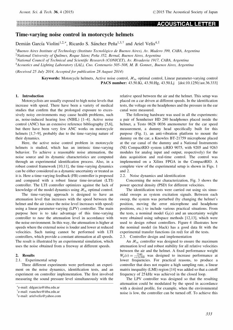
The following hardware was used in all the experiments:a pair of Sennheiser HD 280 headphones placed inside thehelmet, a Testo 0628 0036 anemometer for the car speedmeasurement, a dummy head specifically built for thispurpose (Fig. 1), an anti-vibration platform to mount thedummy on the car, a Knowles BT-21759 microphone placedat the ear canal of the dummy and a National Instruments(NI) CompactRIO system (cRIO 9075, with 9205 and 9263modules for analog input and output, respectively) for thedata acquisition and real-time control. The control wasimplemented on a Xilinx FPGA in the CompactRIO. Acomplete view of the experimental setup is shown in Figs. 1and 2.2.2. Noise dynamics and identification
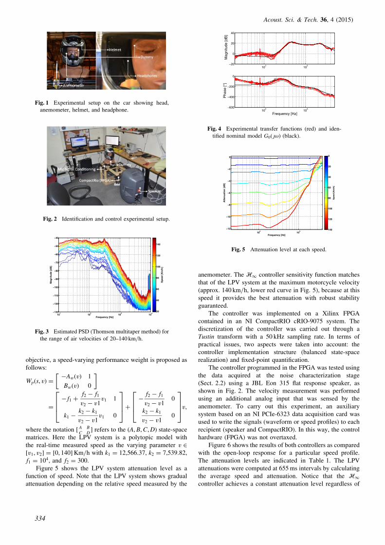
Concerning the noise characterization, Fig. 3 shows thepower spectral density (PSD) for different velocities.
The identification tests were carried out using six sinus-oidal sweeps as system excitation signals. Between eachsweep, the system was perturbed (by changing the helmet’sposition, moving the error microphone and headphonepositions, etc.) to include various practical situations. Fromthe tests, a nominal model G0ðsÞ and an uncertainty weightwere obtained using subspace methods [12,13], which wereused to design robust controllers. Figure 4 illustrates howthe nominal model (in black) has a good data fit with theexperimental transfer functions (in red) for all the tests.2.3. Controller design and implementation
An H1 controller was designed to ensure the maximumattenuation level and robust stability for all relative velocitiesbetween the air and the helmet. A fixed performance weightWpðsÞ ¼ 7540
sþ2�300was designed to increase performance at
lower frequencies. For practical reasons, to produce acontroller that does not require a high sampling rate, a linearmatrix inequality (LMI) region [14] was added so that a cutofffrequency of 25 kHz was achieved in the closed loop.
The LPV controller was designed so that the resultingattenuation could be modulated by the speed in accordancewith a desired profile, for example, when the environmentalnoise is low, the controller can be turned off. To achieve this
�e-mail: [email protected]: [email protected]: [email protected]
333
Acoust. Sci. & Tech. 36, 4 (2015) #2015 The Acoustical Society of Japan
objective, a speed-varying performance weight is proposed asfollows:
Wpðs; vÞ ¼�AwðvÞ 1
BwðvÞ 0
� �
¼� f1 þ
f2 � f1
v2 � v1v1 1
k1 �k2 � k1
v2 � v1v1 0
2664
3775þ
�f2 � f1
v2 � v10
k2 � k1
v2 � v10
2664
3775v;
where the notation ½ A B
C D� refers to the ðA;B;C;DÞ state-space
matrices. Here the LPV system is a polytopic model withthe real-time measured speed as the varying parameter v 2½v1; v2� ¼ ½0; 140�Km/h with k1 ¼ 12;566:37, k2 ¼ 7;539:82,f1 ¼ 104, and f2 ¼ 300.
Figure 5 shows the LPV system attenuation level as afunction of speed. Note that the LPV system shows gradualattenuation depending on the relative speed measured by the
anemometer. The H1 controller sensitivity function matchesthat of the LPV system at the maximum motorcycle velocity(approx. 140 km/h, lower red curve in Fig. 5), because at thisspeed it provides the best attenuation with robust stabilityguaranteed.
The controller was implemented on a Xilinx FPGAcontained in an NI CompactRIO cRIO-9075 system. Thediscretization of the controller was carried out through aTustin transform with a 50 kHz sampling rate. In terms ofpractical issues, two aspects were taken into account: thecontroller implementation structure (balanced state-spacerealization) and fixed-point quantification.
The controller programmed in the FPGA was tested usingthe data acquired at the noise characterization stage(Sect. 2.2) using a JBL Eon 315 flat response speaker, asshown in Fig. 2. The velocity measurement was performedusing an additional analog input that was sensed by theanemometer. To carry out this experiment, an auxiliarysystem based on an NI PCIe-6323 data acquisition card wasused to write the signals (waveform or speed profiles) to eachrecipient (speaker and CompactRIO). In this way, the controlhardware (FPGA) was not overtaxed.
Figure 6 shows the results of both controllers as comparedwith the open-loop response for a particular speed profile.The attenuation levels are indicated in Table 1. The LPVattenuations were computed at 655 ms intervals by calculatingthe average speed and attenuation. Notice that the H1controller achieves a constant attenuation level regardless of
Fig. 1 Experimental setup on the car showing head,anemometer, helmet, and headphone.
Fig. 2 Identification and control experimental setup.
101
102
103
104
−130
−120
−110
−100
−90
−80
−70
−60
−50
−40
Frequency [Hz]
Mag
nit
ud
e [d
B]
Sp
eed
[K
m/h
]
20
40
60
80
100
120
140
Fig. 3 Estimated PSD (Thomson multitaper method) forthe range of air velocities of 20–140 km/h.
102
103
−20
0
20
40
Mag
nitu
de [d
B]
102
103
−600
−400
−200
0
Frequency [Hz]
Pha
se [°
]
Fig. 4 Experimental transfer functions (red) and iden-tified nominal model G0ð|!Þ (black).
102
103
−12
−10
−8
−6
−4
−2
0
Frequency [Hz]
Att
enu
atio
n [
dB
]
Sp
eed
[K
m/h
]
0
20
40
60
80
100
120
140
Fig. 5 Attenuation level at each speed.
Acoust. Sci. & Tech. 36, 4 (2015)
334
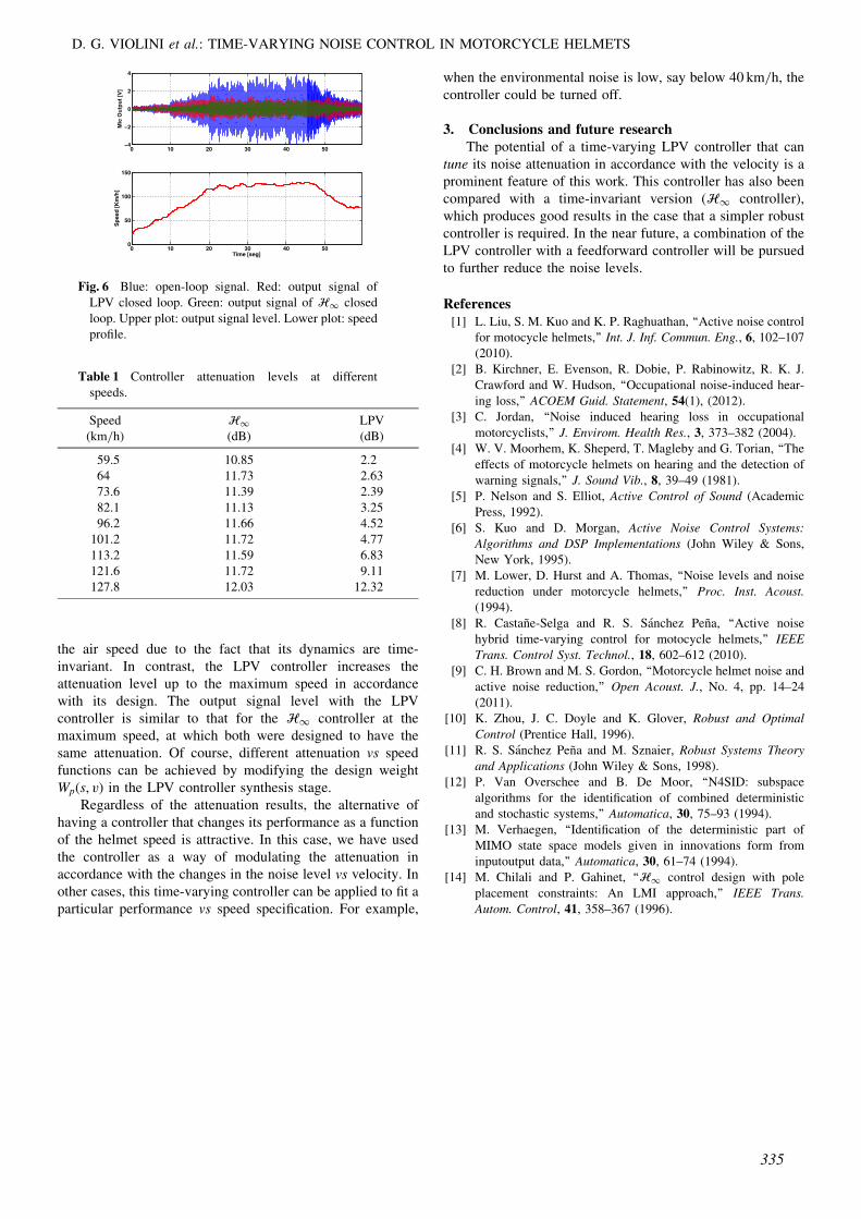
the air speed due to the fact that its dynamics are time-invariant. In contrast, the LPV controller increases theattenuation level up to the maximum speed in accordancewith its design. The output signal level with the LPVcontroller is similar to that for the H1 controller at themaximum speed, at which both were designed to have thesame attenuation. Of course, different attenuation vs speedfunctions can be achieved by modifying the design weightWpðs; vÞ in the LPV controller synthesis stage.
Regardless of the attenuation results, the alternative ofhaving a controller that changes its performance as a functionof the helmet speed is attractive. In this case, we have usedthe controller as a way of modulating the attenuation inaccordance with the changes in the noise level vs velocity. Inother cases, this time-varying controller can be applied to fit aparticular performance vs speed specification. For example,
when the environmental noise is low, say below 40 km/h, thecontroller could be turned off.
3. Conclusions and future researchThe potential of a time-varying LPV controller that can
tune its noise attenuation in accordance with the velocity is aprominent feature of this work. This controller has also beencompared with a time-invariant version (H1 controller),which produces good results in the case that a simpler robustcontroller is required. In the near future, a combination of theLPV controller with a feedforward controller will be pursuedto further reduce the noise levels.
References[1] L. Liu, S. M. Kuo and K. P. Raghuathan, ‘‘Active noise control
for motocycle helmets,’’ Int. J. Inf. Commun. Eng., 6, 102–107(2010).
[2] B. Kirchner, E. Evenson, R. Dobie, P. Rabinowitz, R. K. J.Crawford and W. Hudson, ‘‘Occupational noise-induced hear-ing loss,’’ ACOEM Guid. Statement, 54(1), (2012).
[3] C. Jordan, ‘‘Noise induced hearing loss in occupationalmotorcyclists,’’ J. Envirom. Health Res., 3, 373–382 (2004).
[4] W. V. Moorhem, K. Sheperd, T. Magleby and G. Torian, ‘‘Theeffects of motorcycle helmets on hearing and the detection ofwarning signals,’’ J. Sound Vib., 8, 39–49 (1981).
[5] P. Nelson and S. Elliot, Active Control of Sound (AcademicPress, 1992).
[6] S. Kuo and D. Morgan, Active Noise Control Systems:Algorithms and DSP Implementations (John Wiley & Sons,New York, 1995).
[7] M. Lower, D. Hurst and A. Thomas, ‘‘Noise levels and noisereduction under motorcycle helmets,’’ Proc. Inst. Acoust.(1994).
[8] R. Castane-Selga and R. S. Sanchez Pena, ‘‘Active noisehybrid time-varying control for motocycle helmets,’’ IEEETrans. Control Syst. Technol., 18, 602–612 (2010).
[9] C. H. Brown and M. S. Gordon, ‘‘Motorcycle helmet noise andactive noise reduction,’’ Open Acoust. J., No. 4, pp. 14–24(2011).
[10] K. Zhou, J. C. Doyle and K. Glover, Robust and OptimalControl (Prentice Hall, 1996).
[11] R. S. Sanchez Pena and M. Sznaier, Robust Systems Theoryand Applications (John Wiley & Sons, 1998).
[12] P. Van Overschee and B. De Moor, ‘‘N4SID: subspacealgorithms for the identification of combined deterministicand stochastic systems,’’ Automatica, 30, 75–93 (1994).
[13] M. Verhaegen, ‘‘Identification of the deterministic part ofMIMO state space models given in innovations form frominputoutput data,’’ Automatica, 30, 61–74 (1994).
[14] M. Chilali and P. Gahinet, ‘‘H1 control design with poleplacement constraints: An LMI approach,’’ IEEE Trans.Autom. Control, 41, 358–367 (1996).
0 10 20 30 40 50−4
−2
0
2
4
Mic
Ou
tpu
t [V
]
0 10 20 30 40 500
50
100
150
Time [seg]
Sp
eed
[K
m/h
]
Fig. 6 Blue: open-loop signal. Red: output signal ofLPV closed loop. Green: output signal of H1 closedloop. Upper plot: output signal level. Lower plot: speedprofile.
Table 1 Controller attenuation levels at differentspeeds.
Speed(km/h)
H1(dB)
LPV(dB)
59.5 10.85 2.264 11.73 2.6373.6 11.39 2.3982.1 11.13 3.2596.2 11.66 4.52
101.2 11.72 4.77113.2 11.59 6.83121.6 11.72 9.11127.8 12.03 12.32
D. G. VIOLINI et al.: TIME-VARYING NOISE CONTROL IN MOTORCYCLE HELMETS
335