timber harvester manual
TRANSCRIPT

Mechanical Timber Harvesting HandbookEFFECTIVE JANUARY 1, 2012
OREGON® | Blount, Inc.Corporate HeadquartersP.O. Box 22127Portland, Oregon 97269-2127 USAoregonproducts.com800-223-5168 • 503-653-8881
© Copyright 2012 | Blount, Inc. | F/N A106976 Rev AF 1/12
OREG
ON
® MECH
AN
ICAL TIM
BER H
ARV
ESTING
HA
ND
BOO
K

This handbook provides information that OREGON® considers critical to the successful and safe use of OREGON® saw chain-based cutting systems in mechanized wood harvesting and processing. In offering this information, Oregon® does not assume any responsibility for the design or manufacture of equipment, nor for the content of literature supplied by equipment manufacturers. This handbook is intended for designers, manufacturers, sellers, and users of saw chain-based cutting systems for mechanized wood harvesting/processor machinery.
The saw chain-based cutting system on a mechanized wood harvesting/processor machinery must meet two fundamental objectives:• Performance (production, reliability, life)• SafetyIn saw chain-based cutting systems, a number of interrelated factors influence the degree of success in both performance and safety. This Oregon® Mechanical Timber Harvesting Handbook is intended to assist you in understanding those factors.
OREGON® HARVESTER CHAIN(Not intended for use on handheld chain saws).404" pitch:16H – Micro Chisel® 18HX – Micro Chisel®
3/4" pitch:11BC – Chipper11H – Semi-Chisel
Introduction
This Timber Harvesting Handbook supersedes and replaces all previous OREGON® Timber Harvesting Handbooks.
Blount, Inc. • ©2012

1
Table of ContentsImportant Safety Information
Chain Shot Warning . . . . . . . . . . . . . . . . . . . . . . . . . . . . . . . . . . . . . . . . .2How Chain Shot Happens . . . . . . . . . . . . . . . . . . . . . . . . . . . . . . . . . . .3Machine Operator, Ground Personnel and Bystander Safety . . . . . . . . . . . . . . . . . . . . . . . . . . . . . . . . . . . . . . . . 4 – 5
Cold Weather/Lubrication Recommendations
Cold Weather / Lubrication Information . . . . . . . . . . . . . . . . . . . . .6Cold Conditions Recommendations . . . . . . . . . . . . . . . . . . . . . 6 – 7
Saw Chain
Saw Chain Terms . . . . . . . . . . . . . . . . . . . . . . . . . . . . . . . . . . . . . . . . 8 – 9Saw Chain Tension . . . . . . . . . . . . . . . . . . . . . . . . . . . . . . . . . . . .10 – 11Saw Chain Descriptions, Specifications . . . . . . . . . . . . . . . . .12 – 19Saw Chain Speed . . . . . . . . . . . . . . . . . . . . . . . . . . . . . . . . . . . . .20 – 21Technical Data . . . . . . . . . . . . . . . . . . . . . . . . . . . . . . . . . . . . . . . . . . . . 22Installation and Break In . . . . . . . . . . . . . . . . . . . . . . . . . . . . . . . . . . . 23Saw Chain Sharpening . . . . . . . . . . . . . . . . . . . . . . . . . . . . . . . .24 – 30Saw Chain Repair . . . . . . . . . . . . . . . . . . . . . . . . . . . . . . . . . . . . .31 – 35Troubleshooting . . . . . . . . . . . . . . . . . . . . . . . . . . . . . . . . . . . . . .35 – 42
Guide Bars
Guide Bar Mounts . . . . . . . . . . . . . . . . . . . . . . . . . . . . . . . . . . . . .43 – 57Guide Bar Maintenance . . . . . . . . . . . . . . . . . . . . . . . . . . . . . . .58 – 63Guide Bar Troubleshooting . . . . . . . . . . . . . . . . . . . . . . . . . . . .64 – 72
Drive Sprockets
Drive Sprocket Types & Drive Shafts . . . . . . . . . . . . . . . . . . .73 – 74Drive Sprocket Alignment & Replacement . . . . . . . . . . . . .74 – 76Drive Sprocket Troubleshooting . . . . . . . . . . . . . . . . . . . . . . . . . . . 77Design Information . . . . . . . . . . . . . . . . . . . . . . . . . . . . . . . . . . .78 – 79HarvesterLok™ Sprocket Information . . . . . . . . . . . . . . . . . .80 – 81
Hydraulic Pump Calculations & Specifications . . . . . . . . . .82

2
Important Safety Information
For maximum protection, machines should be equipped with chain catchers, chain shot guards, closed snow holes near the bar tip, appropriate window enclosures and recommendations contained in this handbook and your equipment's operator manuals should be followed .
DO NOT USE SAW CHAIN THAT:• Hasbrokentwice.• Isseverelydamaged.• Hasexcessivesawchainstretch.• Hasbrokenorcrackedcomponents.• Haslooserivetjoints.Ifyoucanrotatetherivetswithyour
fingers, they’re too loose .
GUIDE BAR MOUNT, CHAIN CATCHER, AND CHAIN SHOT GUARD
WARNING: There is risk of serious injury or death to the machine operator, ground personnel and bystanders from chain shot . Chain shot occurs when a piece or pieces of cutting chain from the end of a broken saw chain in mechanized timber harvesting or processing is ejected at a high velocity . Chain shot typically originates near the drive end of the cutting system but can also originate from the guide bar tip area . Saw chain pieces usually travel in the cutting plane of the guide bar, but can deviate to either side (see illustration page 4) . Although the shot cone reflects the most likely chain shot path, deflections can occur, substantially expanding where chain pieces may travel .
Direction of chain travelDrivesprocket
Chaincatcher Bar
groove
Insidemount pad
Pivot armmount pad
GuidebarChain
shotguard
Outsidemount
pad
3
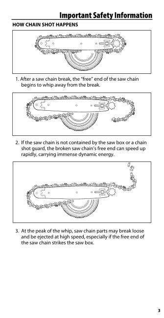
Important Safety InformationHOW CHAIN SHOT HAPPENS
1 . After a saw chain break, the “free” end of the saw chain begins to whip away from the break .
2 . If the saw chain is not contained by the saw box or a chain shot guard, the broken saw chain’s free end can speed up rapidly, carrying immense dynamic energy .
3 . At the peak of the whip, saw chain parts may break loose andbeejectedathighspeed,especiallyifthefreeendofthe saw chain strikes the saw box .

4
Important Safety Information
SHOT CONE ZONE SHOT CONE ZONE
Chain shot can cause saw chain parts to be thrown in many directions along the cutting plane of the saw guide bar (as shown in the illustration above) . The shot cone zone (see illustration below) reflects where saw chain pieces usually travel, unless pieces are deflected .
MACHINE OPERATOR, GROUND PERSONNEL AND BYSTANDER SAFETYGuards and Shields: Because of the high speeds, high stress, heavy loads, wear factors, and varying levels of repair and maintenance given to saw chain-based mechanized wood harvesters/processors, there is a possibility that saw chain or saw chain pieces can be thrown from the machine at high speed and with immense energy . Machine operators, ground personnel and bystandersareexposedtoariskofseriousinjuryordeath.
Equipment should be designed with appropriate guards, shields, window enclosures and care should be taken to minimize the exposure of the machine operator, ground personnel and bystanders to the cutting plane of the saw . Bystanders and ground personnel should be kept at least 230 feet way .

5
Important Safety InformationWindows: Window glazing in operator’s enclosures should comply with the local codes for impact resistance .
Chain Catcher: A chain catcher can assist in containing thrown saw chain, and is a complement to guards and shields . The chain catcher can be a sturdy rod or similar device placed perpendicular to the center of the drive sprocket . It can be mounted either to the drive shaft, or to the saw box, with a narrow gap to allow for safe saw chain installation and removal .
Chain Shot Guard: A chain shot guard is a piece of material mounted behind the drive sprocket . This guard performs two functions:
• Absorbstheenergyofabrokensawchaincomingincontactwith the saw box, and prevents saw chain parts from breakingoffandbeingejected.
• Actsasanextensionofthesawbox,reducingtheopportunity for thrown saw chain or saw chain parts to escape the saw box .
Operational Recommendations:
• Neverengageinacutwith ground personnel or bystanders in the shot cone zone .
• Alwaysengageinacutas close to the ground as possible .
Chaincatcher
Chainshotguard

6
Cold Conditions RecommendationsLUBRICATIONYour cutting system (saw chain and guide bar) must receive sufficient lubrication to prevent excessive chassis wear .
The minimum amount of lubrication recommended for .404"-pitch cutting systems is 2 cubic inches/minute (33 cc/min) which equates to a minimum of two gallons (8 liters) per eight-hour shift in a harvesting application . For 3/4"-pitch cutting systems the minimum recommended is 2 .5 cubic inches/minute (40 cc/min) or a minimum of 2 .5 gallons (10 liters) per
eight-hour shift in a harvesting application .
A practice on some machinery is to use hydraulic fluid to lubricate the cutting system . Hydraulic fluid is not an adequate cutting system lubricant .
At startup, adequate time must be allowed for lubrication to reach the cutting system . In cold weather, or with the addition of a new guide bar or saw chain, the system will require additional time . Run the saw chain slowly while cycling the guide bar until lubrication can be observed leaving the tip of the guide bar .
To minimize debris in your lubrication systems, install a fine screen into the fill port .
COLD WEATHER USECutting frozen wood can cause heavy wear on the saw chain chassis and can create cracks resulting in possible breakage . Following our maintenance recommendations can reduce the amount of wear and extend the service life of the cutting system .
COLD CONDITIONS RECOMMENDATIONSRecommendations for maximizing service life of your cutting
systems in cold conditions:
Lubrication• Usealight(winter)weightlubricant,if
possible doubling the flow rate .
• Periodicallycycletheguidebarwithoutcutting (air cuts) to increase lubrication present on the cutting system and to ensure the lubrication system is working .

7
Cold Conditions RecommendationsBAR FEED FORCE• Reduceguidebarfeedforceorfeedspeed.
GUIDE BAR
Maintenance• Cleantheguidebargroove(fromtiptotail)andkeeptheoil
holes open .• Turnguidebarovertoequalizewear.Recommendedona
DAILY basis .
Shut Down Procedure• Cycleguidebarseveraltimestoremovemoisturefrom
guide bar tip .
SAW CHAIN
Tension• Maintainpropertension• Checkoften.
Shut Down Procedure• Atbreaksandattheendofeachshift,relievesawchain
tension to prevent damage to the guide bar tip, saw motor and/or saw chain as the saw chain cools and contracts .
Sharpening• Maintaincuttersinagreementwiththemanufacturer’s
recommendations.ForOREGON®harvesterchain,referto pages 25 – 27 or our "Optional Sharpening Modification" on page 30 .
• Neverforceadullsawchaintocut.• OREGON®recommendssharpeningsawchainatleastonce
per shift or when saw chain becomes dull in agreement with maintenance recommendations contained in this handbook .
Cutter Depth Gauges• Checkcutterdepthgaugesateachsharpening• Adjustasnecessary(Slightly reduced depth gauge settings will
help extend service life under these extreme conditions.)• Neverlowerdepthgaugesmorethattherecommended
setting . This will cause saw chain chassis to wear prematurely . See depth gauge settings page 26 .
Breakage• Discardsawchainafteritssecondbreak.
Saw Chain Speed• Reducesawchainspeed
8
SAW
CHAI
N
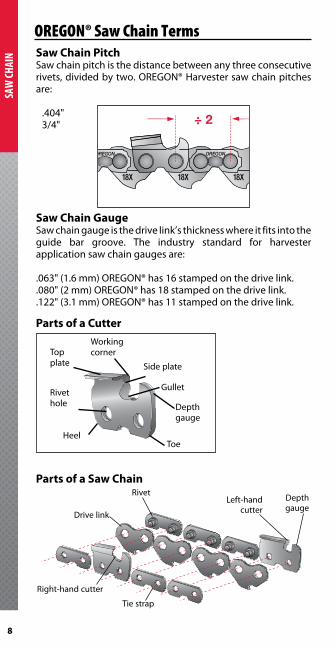
OREGON® Saw Chain TermsSaw Chain PitchSaw chain pitch is the distance between any three consecutive rivets,dividedbytwo.OREGON®Harvestersawchainpitchesare:
.404"3/4"
Saw Chain GaugeSaw chain gauge is the drive link’s thickness where it fits into the guide bar groove . The industry standard for harvester application saw chain gauges are:
.063"(1.6mm)OREGON®has16stampedonthedrivelink.
.080"(2mm)OREGON®has18stampedonthedrivelink.
.122"(3.1mm)OREGON®has11stampedonthedrivelink.
Parts of a Cutter
Parts of a Saw Chain
OREGON
18X 18X 18X
OREGON
Working cornerTop
plate
Rivet hole
HeelToe
Depth gauge
Gullet
Side plate
Rivet
Drive link
Right-hand cutter
Tie strap
Left-hand cutter
Depth gauge
9
SAW CHAIN
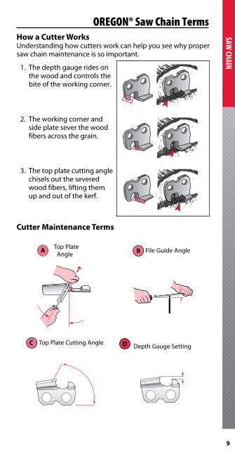
OREGON® Saw Chain TermsHow a Cutter WorksUnderstandinghowcuttersworkcanhelpyouseewhypropersaw chain maintenance is so important .
1 . The depth gauge rides on the wood and controls the bite of the working corner .
2 . The working corner and side plate sever the wood fibers across the grain .
3 . The top plate cutting angle chisels out the severed wood fibers, lifting them up and out of the kerf .
Cutter Maintenance Terms
Top Plate Angle B File Guide Angle
C Top Plate Cutting Angle Depth Gauge Setting
A
D

10
SAW
CHAI
N
OREGON® Saw Chain TensionSAW CHAIN TENSIONTo minimize wear on the guide bar and saw chain, saw chain tension for hard nose guide bars should be tight (the length of a drive link tangs at the mid-point of the guide bar should nearly come out of the bar groove) and tighter for sprocket nose guide bars (1/8" at the mid-point of the guide bar) .
Manual TensioningAs a rule, saw chain should be tight enough so the chassis of the saw chain is pulled firmly against the guide bar around the perimeter of the guide bars .
Tension must be checked periodically .
Saw chain should only be tensioned when it is cool . Steel expands when hot and contracts when cool . Tensioning a hot saw chain can damage your cutting system and drive motor as it cools and contracts .
Checking TensionTo check for proper tension grasp the saw chain at mid-span of the guide bar with your thumb and forefinger and pull the saw chain away from the rails .
For hard-nose guide bars, the drive link tangs should nearly come out of the guide bar groove .
For sprocket nose guide bars, the saw chain come out of the guide bar groove about 1/8" (approximately 3 mm) and then snap back into the guide bar groove .
1/8"
Shut Down ProcedureAt breaks and the end of the shift, relieve saw chain tension to prevent damage as it cools and contracts .
11
SAW CHAIN
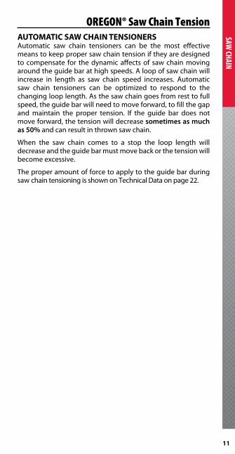
OREGON® Saw Chain TensionAUTOMATIC SAW CHAIN TENSIONERSAutomatic saw chain tensioners can be the most effective means to keep proper saw chain tension if they are designed to compensate for the dynamic affects of saw chain moving around the guide bar at high speeds . A loop of saw chain will increase in length as saw chain speed increases . Automatic saw chain tensioners can be optimized to respond to the changing loop length . As the saw chain goes from rest to full speed, the guide bar will need to move forward, to fill the gap and maintain the proper tension . If the guide bar does not move forward, the tension will decrease sometimes as much as 50% and can result in thrown saw chain .
When the saw chain comes to a stop the loop length will decrease and the guide bar must move back or the tension will become excessive .
The proper amount of force to apply to the guide bar during saw chain tensioning is shown on Technical Data on page 22 .
12
SAW
CHAI
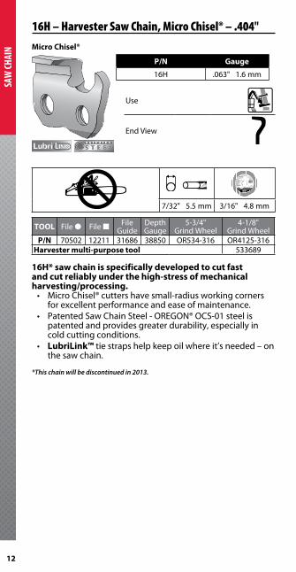
N Micro Chisel®
P/N Gauge
16H .063" 1 .6 mm
Use
End View
Grinding Wheel• Maximum Speed: 4,500 rpm
• Do not use beyond edge of label• Replace with OR534-316
Meule• Vitesse maximum : 4 500 tr/min
• Ne pas utiliser au delà du bord de l'étiquette
• Remplacer avec OR534-316
Disco abrasivo• Velocidad máxima: 4,500 rpm• No utilizar más allá del borde de la etiqueta.• Reemplazar con repuestos Nº OR534-316
For use on/Utiliser avec/ Utilice con:
Oregon® 510A, 511A-BC,511AX, 109179Carlton® 78-120VTilton TL150, TL900
Windsor® 12W1115
Blount, Inc.oregonchain.com
F/N 102528 Rev AE 5/09
5-3/4" x 3/16" x 7/8"146 mm x 4.8 mm x 22.3 mm
7/32" 5 .5 mm 3/16" 4 .8 mm
TOOL File ● File ■ File Guide
Depth Gauge
5-3/4" Grind Wheel
4-1/8" Grind Wheel
P/N 70502 12211 31686 38850 OR534-316 OR4125-316Harvester multi-purpose tool 533689
16H* saw chain is specifically developed to cut fast and cut reliably under the high-stress of mechanical harvesting/processing .• MicroChisel®cuttershavesmall-radiusworkingcorners
for excellent performance and ease of maintenance .• PatentedSawChainSteel-OREGON®OCS-01steelis
patented and provides greater durability, especially in cold cutting conditions .
• LubriLink™ tie straps help keep oil where it’s needed – on the saw chain .
*This chain will be discontinued in 2013.
16H – Harvester Saw Chain, Micro Chisel® – .404"

13
SAW CHAIN
16H – Harvester Saw Chain, Micro Chisel® – .404"
|X| A B C D
16H 7/32" 35° 10° 80° .050" 1 .27 mm
16H 3/16" 35° 10° 60° .050" 1 .27 mm
14
SAW
CHAI
N
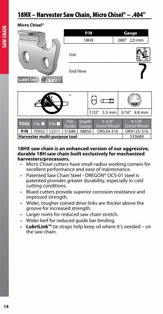
18HX – Harvester Saw Chain, Micro Chisel® – .404"Micro Chisel®
P/N Gauge
18HX .080" 2 .0 mm
Use
End View
* Grinding Wheel• Maximum Speed: 4,500 rpm
• Do not use beyond edge of label• Replace with OR534-316
Meule• Vitesse maximum : 4 500 tr/min
• Ne pas utiliser au delà du bord de l'étiquette
• Remplacer avec OR534-316
Disco abrasivo• Velocidad máxima: 4,500 rpm• No utilizar más allá del borde de la etiqueta.• Reemplazar con repuestos Nº OR534-316
For use on/Utiliser avec/ Utilice con:
Oregon® 510A, 511A-BC,511AX, 109179Carlton® 78-120VTilton TL150, TL900
Windsor® 12W1115
Blount, Inc.oregonchain.com
F/N 102528 Rev AE 5/09
5-3/4" x 3/16" x 7/8"146 mm x 4.8 mm x 22.3 mm
7/32" 5 .5 mm 3/16" 4 .8 mm
TOOL File ● File ■ File Guide
Depth Gauge
5-3/4" Grind Wheel
4-1/8" Grind Wheel
P/N 70502 12211 31686 38850 OR534-316 OR4125-316Harvester multi-purpose tool 533689
18HX saw chain is an enhanced version of our aggressive, durable 18H saw chain built exclusively for mechanized harvesters/processors .• MicroChiselcuttershavesmall-radiusworkingcornersfor
excellent performance and ease of maintenance .• PatentedSawChainSteel-OREGON®OCS-01steelis
patented provides greater durability, especially in cold cutting conditions .
• Bluedcuttersprovidesuperiorcorrosionresistanceandimproved strength .
• Wider,toughercoineddrivelinksarethickerabovethegroove for increased strength .
• Largerrivetsforreducedsawchainstretch.• Widerkerfforreducedguidebarbinding.• LubriLink™ tie straps help keep oil where it’s needed – on
the saw chain .

15
SAW CHAIN
18HX – Harvester Saw Chain, Micro Chisel® – .404"
|X| A B C D
18HX 7/32" 35° 10° 80° .050" 1 .27 mm
18HX 3/16" 35° 10° 60° .050" 1 .27 mm
16
SAW
CHAI
N
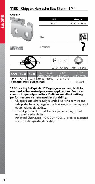
11BC – Chipper, Harvester Saw Chain – 3/4"Chipper
P/N Gauge
11BC .122" 3 .1 mm
Use
End View
* Grinding Wheel• Maximum Speed: 4,500 rpm
• Do not use beyond edge of label• Replace with OR534-316
Meule• Vitesse maximum : 4 500 tr/min
• Ne pas utiliser au delà du bord de l'étiquette
• Remplacer avec OR534-316
Disco abrasivo• Velocidad máxima: 4,500 rpm• No utilizar más allá del borde de la etiqueta.• Reemplazar con repuestos Nº OR534-316
For use on/Utiliser avec/ Utilice con:
Oregon® 510A, 511A-BC,511AX, 109179Carlton® 78-120VTilton TL150, TL900
Windsor® 12W1115
Blount, Inc.oregonchain.com
F/N 102528 Rev AE 5/09
5-3/4" x 3/16" x 7/8"146 mm x 4.8 mm x 22.3 mm
5/16" 7 .9 mm 5/16" 7 .9 mm
TOOL File ● File ■ File Guide
Depth Gauge
5-3/4" Grind Wheel
4-1/8" Grind Wheel
P/N 90410 12211 31686 26800 OR534-316 -Harvester multi-purpose tool 533700
11BC is a big 3/4"-pitch .122"-gauge saw chain, built for mechanical harvester/processor applications . Features classic chipper-style cutters . Delivers excellent cutting performance with heavyweight durability .• Chippercuttershavefullyroundedworkingcornersand
side plates for a big, aggressive bite, easy sharpening, and edge-holding durability .
• Tested,provenchassisdeliverssuperiorstrengthandoutstanding durability .
• PatentedChainSteel–OREGON®OCS-01steelispatentedand provides greater durability .
17
SAW CHAIN
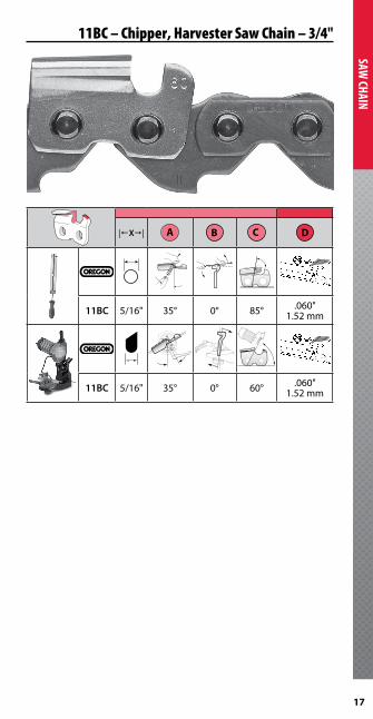
11BC – Chipper, Harvester Saw Chain – 3/4"
|X| A B C D
11BC 5/16" 35° 0° 85° .060" 1 .52 mm
11BC 5/16" 35° 0° 60° .060" 1 .52 mm

18
SAW
CHAI
N
11H – Semi-Chisel, Harvester Saw Chain – 3/4"Semi-Chisel
P/N Gauge
11H .122" 3 .1 mm
Use
End View
* Grinding Wheel• Maximum Speed: 4,500 rpm
• Do not use beyond edge of label• Replace with OR534-316
Meule• Vitesse maximum : 4 500 tr/min
• Ne pas utiliser au delà du bord de l'étiquette
• Remplacer avec OR534-316
Disco abrasivo• Velocidad máxima: 4,500 rpm• No utilizar más allá del borde de la etiqueta.• Reemplazar con repuestos Nº OR534-316
For use on/Utiliser avec/ Utilice con:
Oregon® 510A, 511A-BC,511AX, 109179Carlton® 78-120VTilton TL150, TL900
Windsor® 12W1115
Blount, Inc.oregonchain.com
F/N 102528 Rev AE 5/09
5-3/4" x 3/16" x 7/8"146 mm x 4.8 mm x 22.3 mm
5/16" 7 .9 mm 5/16" 7 .9 mm
TOOL File ● File ■ File Guide
Depth Gauge
5-3/4" Grind Wheel
4-1/8" Grind Wheel
P/N 90410 12211 107529 26800 OR534-516 -Harvester multi-purpose tool 533700
Putting semi-chisel cutters on a 3/4"-pitch saw chain, the 11H cutter features more aggressive grind angles for maximum performance on more powerful machines .• Semi-chiselcuttersmake11Hanaggressive,
high-performance saw chain .• Tested,provenchassisdeliverssuperiorstrengthand
outstanding durability .• PatentedSawChainSteel–OREGON®OCS-01steelis
patented and provides greater durability, especially in cold cutting conditions .
• Advancedchromeplatingprocessforexcellentstay-sharpand edge-holding durability .
• 11Hcuttersprovidewidergullets,longerstay-sharp,and an offset footprint to help minimize guide bar “knife-edging .”

19
SAW CHAIN
11H – Semi-Chisel, Harvester Saw Chain – 3/4"
|X| A B C D
11H 5/16" 30° 0° 80° 060" 1 .52 mm
11H 5/16" 30° 0° 80° .070" 1 .78 mm
11H 5/16" 30° 0° 50° .060" 1 .52 mm
11H 5/16" 30° 0° 80° 070" 1 .778 mm
11H cutters are set to .060"/1 .52 mm at the factory and should be left at those settings for cold cutting conditions . In other conditions, .070"/1 .788 mm will yield better cutting performance .

20
SAW
CHAI
N SAW CHAIN SPEED, FEED FORCE, SERVICE LIFE, AND SAFETYIt is well recognized higher saw chain speeds and/or guide bar feed forces with sufficient power input generally equate to faster cutting speeds, but at a cost to a cutting system in shortened service life .Exceeding our guidelines for recommended cutting system maintenance, saw chain speed and feed forces will result in increased wear, shorter cutting system service life, and increase the potential for a chain shot event and potential injury or death . At no time should the maximum saw chain speed be exceeded .
SAW CHAIN SPEED AND FEED FORCESaw chain speed may be calculated according to the formula below . For quick reference, the charts on page 21 show saw chain speed as a function of the drive sprocket tooth count for a variety of saw chains and over a range of drive shaft speeds .
Our recommendations for saw chain speed and feed-force are supplied in the Technical Data tables on page 22 . These guidelines are intended to provide a balance between performance and cutting system service life (wear) . When our recommendations for cutting system maintenance, saw chain speed and guide bar feed-forces are exceeded, it will result in:
1 . Reduced cutting system service life2 . Will require extra lubrication3 . Increased potential for a saw chain shot event and
potentialinjuryordeathtooperators,groundpersonneland bystanders
SAW CHAIN SPEED CALCULATION
SPEED = (RPM) x (T) x (P) RPM = Motor or drive shaft revolutions per minute T = Numberofteethondrivesprocket P1 = Saw chain pitch factor for ft/min P2 = Saw chain pitch factor for m/sec
FACTOR
Saw Chain Pitch P1 P2
.404" .067 .00034
3/4" .131 .00066
OREGON® Saw Chain Information

21
SAW CHAIN
ESTIMATING CUTTING RATEWhen running at recommended saw chain speeds (see tables that follow), an estimate of soft-wood cutting rate may be calculated according to the following expression:
CUTTING RATE = (FACTOR) x (Hp) Hp = Horsepower input to saw chain F1 = Factor for in2/sec F2 = Factor for cm2/sec
These recommendations apply to OREGON® brand saw chain only, and are not meant to apply to any other saw chain brand.
FACTORSaw Chain Pitch F1 F2
.404" 3 .5 22 .63/4" 2 .8 18 .1
SAW CHAIN SPEED – .404" PITCH
FEET
/MIN
UTE
9000 45
MET
ERS/
SECO
ND
S
8000 40
7000 35
6000 30
5000 25
4000 20
3000 5000 5500 6000 6500 7000 7500 8000 8500 9000 9500 10000DRIVE SHAFT SPEED (RPM)
Recommended & Maximum .404" saw chain speed: 8000 ft/min (40 m/s)
9 TOOTH10 TOOTH11 TOOTH12 TOOTH13 TOOTH14 TOOTH15 TOOTH16 TOOTH17 TOOTH
18 TOOTH
SAW CHAIN SPEED – 3/4" PITCH
FEET
/MIN
UTE
8000 40
MET
ERS/
SECO
ND
S
7000 35
6000 30
5000 25
4000 20
3000 15
2000 2500 3000 3500 4000 4500 5000 5500 6000DRIVE SHAFT SPEED (RPM)
Recommended 3/4" saw chain speed: 6000 ft/min (30 m/s)Maximum 3/4" saw chain speed: 7000 ft/min (35 m/s)
10 TOOTH
9 TOOTH
8 TOOTH
7 TOOTH
OREGON® Saw Chain Information

22
SAW
CHAI
N TECHNICAL DATA (ENGLISH UNITS)
TECHNICAL DATA (METRIC UNITS)
OREGON® SAW CHAIN NUMBER .404" pitch 3/4" pitch16H 18HX 11BC 11H
PHYSICAL PROPERTIESWeight, lbs./ft. 0.220 0.261 0.640 0.630Tensile strength, lbs. 2600 2700 6700 6700Kerf, in. 0.34 0.36 0.57 0.57Gauge, in. 0.063 0.080 0.121 0.121Actual pitch, in. 0.4055 0.4055 0.7835 0.7835Cutter height, in. 0.542 0.562 1.003 1.005Guide bar thickness, in. min/max 0.225/0.237 0.238/0.252 0.355/0.410 0.355/0.410Drive sprocket thickness, in. 0.46 0.46OPERATING PARAMETERSGuide bar/Saw chain oil
Cubic inches/min 2.0 2.0 2.5 2.5Cubic inches/stroke 0.5 0.5 0.6 0.6
Power, hp min/max 5/60 5/65 5/90 10/100Force on guide bar to tension saw chain, lbs.
110 110 150 150
Guide bar feed load, at center, lbs.min/max 30/180 30/200 30/300 30/300recommended 135 150 200 200
Saw chain speed, ft./minmin/max 3000/8000 3000/8000 1500/7000 1500/7000recommended 8000 8000 6000 6000
Min. guide bar adjustment, in/in. of guide bar
0.015 0.015 0.019 0.019
OREGON® SAW CHAIN NUMBER .404" pitch 3/4" pitch16H 18HX 11BC 11H
PHYSICAL PROPERTIESMass, kg/m 0.327 0.388 0.953 0.937Tensile Strength, N 11500 12000 30000 30000Kerf, mm 8.6 9.1 14.5 14.5Gauge, mm 1.6 2.0 3.1 3.1Actual pitch, mm 10.30 10.30 19.90 19.90Cutter height, mm 13.8 14.3 25.5 25.5Guide bar thickness, mm min/max 5.7/6.0 6.0/6.4 9.0/10.4 9.0/10.4Drive sprocket thickness, mm 12 12OPERATING PARAMETERSGuide bar/Saw chain oil
cc/min 30 30 40 40cc/stroke 8 8 10 10
Power, kW min/max 5/45 5/50 5/65 5/75Force on guide bar to tension saw chain, N
490 490 668 668
Guide bar feed load, at center, Nmin/max 100/800 100/900 100/1300 100/1300recommended 600 700 900 900
Saw chain speed, m/secmin/max 15/40 15/40 10/35 10/35recommended 40 40 30 30
Min. guide bar adjustment, cm/cm of guide bar
0.15 0.15 0.19 0.19
OREGON® Saw Chain Information
23
SAW CHAIN
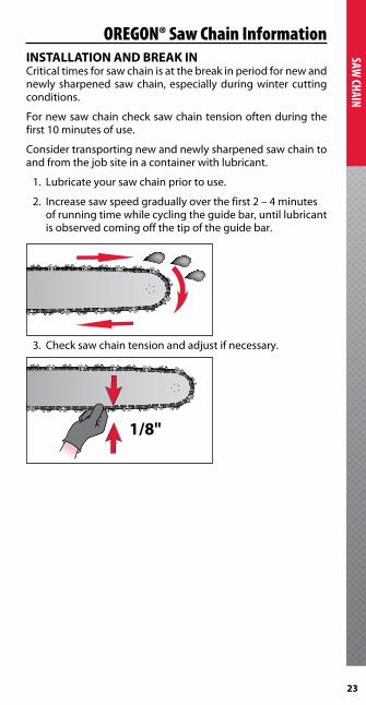
OREGON® Saw Chain InformationINSTALLATION AND BREAK INCritical times for saw chain is at the break in period for new and newly sharpened saw chain, especially during winter cutting conditions .
For new saw chain check saw chain tension often during the first 10 minutes of use .
Consider transporting new and newly sharpened saw chain to andfromthejobsiteinacontainerwithlubricant.
1 . Lubricate your saw chain prior to use .
2 . Increase saw speed gradually over the first 2 – 4 minutes of running time while cycling the guide bar, until lubricant is observed coming off the tip of the guide bar .
3. Checksawchaintensionandadjustifnecessary.
1/8"

24
SAW
CHAI
N
Saw Chain MaintenanceHOW TO SHARPEN SAW CHAIN
DO NOT USE SAW CHAIN THAT:• Hasbrokentwice.Industrygroupsrecommenddiscarding
saw chain after the second break .• Isseverelydamaged.• Hasexcessivestretch/wear.• Hasbrokenorcrackedcomponents.• Haslooserivetjoints.Ifyoucanrotatetherivetswithyour
fingers, they’re too loose .1 . Always wear protective gloves and
safety glasses when handling saw chain .2 . Before sharpening, clean, inspect, repair,
replace or discard damaged saw chain .Remember! If it has broken twice, discard the saw chain!3 . During your inspection,
check for each of the following:
• Properinstallationofsawchain components .
• Cracked,bent,orbrokensaw chain components .
• Cracksonthefootprintofthe cutters and tie-straps .
• Groundcontactdamageonthecutters.Ç• Excessive saw chain stretch. (UseOREGON®stretchgauge
tools to measure .)• Abnormalchassiswear,orwearpatternsonthechassis
that indicate a worn guide bar or drive sprocket .
• Looserivets.
WARNING: There is risk of serious injury or death to the machine operator, ground personnel and bystanders from chain shot . Chain shot occurs when a piece or pieces of cutting chain from the end of a broken saw chain in mechanized timber harvesting or processing is ejected at a high velocity . Chain shot typically originates near the drive end of the cutting system but can also originate from the guide bar tip area . Saw chain pieces usually travel in the cutting plane of the guide bar, but can deviate to either side (see illustration page 4) . Although the shot cone reflects the most likely chain shot path, deflections can occur, substantially expanding where chain pieces may travel .
533689 .404" pitch
533700 3/4" pitch
Multi-purpose tool & stretch gauge

25
SAW CHAIN
4 . Do not re-use saw chain that• Hasbrokentwice• Hasbrokencomponents• Hasbeenseverelydamaged• Hasexcessivestretch• Haslooserivetjoints• Hastoomuchplay(loosechassiscomponents)
5 . Sharpen in agreement with the manufacturer’s recommendations .
• Grindtogoodchrome,keepingallcuttergeometryequal.• Avoidburnedcuttersbyusinglightintermittentstrokes
and dressing the grinding wheel often .• Nevergrindintochassiscomponents.• Dressthegrindingwheeloften.
6. UsethecorrectsharpeningspecificationsforyourOREGON®sawchaintype.Seepages12through19.
• IfunsureofyourOREGON®sawchaintypeorpartnumber,askyourOREGON®sawchaindealer.
• Forsharpeningsawchainwithagrinder,seepages 26 – 28 .
• Forsharpeningsawchainwitharoundfileseepages 28 – 29 .
7. Checkandadjustdepthgauges.Seepage29forinstructions .
8 . After sharpening the saw chain, clean off any particles of material,thenLUBRICATETHESAWCHAINTHOROUGHLYWITHGUIDEBAROIL.
SHARPENING & MAINTENANCE TOOLS
See page 26 for more detail on sharpening angles .
16H 31686 40458 – 70502 12211 38850 OR 534-316 OR 4125-316 53368918HX 31686 40458 – 70502 12211 38850 OR 534-316 OR 4125-316 533689
11BC 107617 – 90410 – 12211 26800 OR 534-516 – 53370011H 107617 – 90410 – 12211 26800
107529OR 534-516 – 533700
Saw Chain Maintenance

26
SAW
CHAI
N
Saw Chain MaintenanceSHARPENING ANGLES
A
B
50 = .050" = 60 = .060"
D
C
FILING AND GRINDING ANGLES
11H cutters are set to .060"/1 .52 mm at the factory and should be left at those settings for cold cutting conditions . In other conditions, .070"/1 .788 mm will yield better cutting performance .
|X| A B C D
16H 7/32" 35° 10° 80° .050" 1 .27 mm
18HX 7/32" 35° 10° 80° .050" 1 .27 mm
11BC 5/16" 35° 0° 85° .060" 1 .52 mm
11H 5/16" 30° 0° 80° 060" 1 .52 mm
11H 5/16" 30° 0° 80° 070" 1 .778 mm
16H 3/16" 35° 10° 60° .050" 1 .27 mm
18HX 3/16" 35° 10° 60° .050" 1 .27 mm
11BC 5/16" 35° 0° 60° .060" 1 .52 mm
11H 5/16" 30° 0° 50° 060" 1 .52 mm
11H 5/16" 30° 0° 50° 070" 1 .778 mm

27
SAW CHAIN
SHARPENING SAW CHAIN WITH A GRINDER
NOTE: Wear safety goggles .
1 . Set vise assembly to the proper top plate filing angle . See previous page for correct angles .
2 . To set the proper grinder head angle, use the recommended top plate cutting angle . See previous page for correct angles .
3 . Dress vitrified grinding wheel often to maintain correct shape.Useeitherrotarywheeldresserordressingbrick.
Top plate filing angle
35°
Top plate filing angle
Side plateangle
1/8" – Flat3/16"
RadiusFull Radius
Side plateangle
50°
1/8" (3.17 mm)Flat
3/16" (4.76 mm)Radius50°
Full Radius
Saw Chain Maintenance

28
SAW
CHAI
N
Saw Chain Maintenance
• Toavoidburningcutters,use light, intermittent strokes .
• Nevergrindintoothersaw chain components .
• Ifdamageispresentonthe chrome surface of top plate or side plate, grind back until damage is removed .
• Keepallcutterlengthsequal.
SHARPENING SAW CHAIN WITH A ROUND FILE1 . Be sure 1/5th or 20%
of the file’s diameter is always held above the cutter’stopplate.Usingthe correct file guide is a the easiest way to hold the file in this position .
2. Keepthecorrecttop plate filing angle line on your file guide parallel with your saw chain .
3 . Sharpen cutters on one side of the saw chain first . File from the inside of each cutter to the outside . Then turn your chain saw around and repeat the process for cutters on the other side of the saw chain .
4 . If damage is present on the chrome surface of top plates or side plates, file back until such damage is removed .
Burned cutter
60= 1/5th or 20% above top plate
File holder
Direction of stroke
inside
outside
29
SAW CHAIN
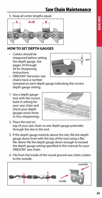
5. Keepallcutterlengthsequal.
HOW TO SET DEPTH GAUGES• Cuttersshouldbe
sharpened before setting the depth gauge . See pages 24 through 29 for sharpening instructions .
• OREGON®Harvestersawchains have a number stamped on each depth gauge indicating the correct depth gauge setting .
1. Useadepthgaugetool with the correct built-in setting for your saw chain and check your depth gauges every three or four sharpenings .
2 . Place the tool on top of your saw chain so one depth gauge protrudes through the slot in the tool .
3 . If the depth gauge extends above the slot, file the depth gauge down level with the top of the tool using a flat file.Neverfilethedepthgaugedownenoughtoexceedthe depth gauge setting specified in this manual for your OREGON®sawchain.
4 . File from the inside of the round ground saw chain cutters to the outside .
A A=B B
.060"60
inside
outside
Saw Chain Maintenance

30
SAW
CHAI
N
Saw Chain MaintenanceOPTIONAL SHARPENING MODIFICATIONSFor optimum life and cutting speed the sharpening specifications can be modified . See page 26 for factory specifications .
Modify sharpening angles from factory specifications as noted below to optimize for specific cutting conditions .
Top plate filing angle
A
Side plate angle
B
Top plate cutting angle
C
Depth gauge setting
D
Cutting conditions16H & 18HXFactory 35° 80° 60° .050"Softwood 40° 70° 60° .050"Hardwood 35° 80° 60° .050"Frozen wood 40° 85° 60° .040"11BCFactory 35° 85° 60° .060"Softwood 40° 75° 60° .060"Hardwood 35° 85° 60° .060"Frozen wood 40° 90° 60° .050"11HFactory 30° 80° 50° .060"Softwood 35° 70° 50° .070"Hardwood 30° 80° 50° .070"Frozen wood 25° 85° 50° .060"

31
SAW CHAIN
Saw Chain RepairHOW TO BREAK OUT RIVETS
For maximum protection, machines should be equipped with saw chain shot guards, saw chain catchers, appropriate window enclosures, and follow recommendations contained in this handbook and your equipment’s operator manuals .
Note: Wear safety goggles and gloves .
1 . Select appropriate anvil . See pages 12 through 19 to determine proper pitch .
2 . Select proper anvil slot number on saw chain breaker anvil which matches the drive link number on the saw chaintobebroken(seeSawChainDriveLinkNumberChart below) .
WARNING: There is risk of serious injury or death to the machine operator, ground personnel and bystanders from chain shot . Chain shot occurs when a piece or pieces of cutting chain from the end of a broken saw chain in mechanized timber harvesting or processing is ejected at a high velocity . Chain shot typically originates near the drive end of the cutting system but can also originate from the guide bar tip area . Saw chain pieces usually travel in the cutting plane of the guide bar, but can deviate to either side (see illustration page 4) . Although the shot cone reflects the most likely chain shot path, deflections can occur, substantially expanding where chain pieces may travel .
70
70
OREGON
70
11111111
3/470
SAW CHAIN DRIVE LINK NUMBER CHARTAnvil slot number Drive link number
.404" 163/4" 11
18HX 18

32
SAW
CHAI
N
Saw Chain Repair
3 . Insert saw chain portion for breaking into the proper slot of the saw chain anvil and push saw chain forward until bottom tie strap is flush with the far side of slot . (Drive link is then supported on both sides of slot .)
4 . Position rivet head directly under punch . Pull handle down if using a bench saw chain breaker, or hammer out rivet of using a handheld punch . Do not use excessive force .
NOTE: Important– when breaking saw chain at cutter, make sure cutter is in the top position.
REMOVING RIVETS FROM BROKEN DRIVE LINKS1 . When removing rivets from broken drive links, hold
the two broken segments together in their original (unbroken) positions as you tighten the saw chain link in theadjustableanvil.
2 . Repeat steps 3 and 4 from “How to Break Out Rivets .”
3/43/4
33
SAW CHAIN
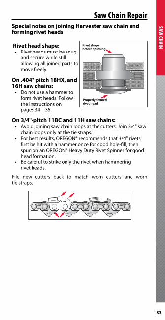
Saw Chain RepairSpecial notes on joining Harvester saw chain and forming rivet heads
Rivet head shape:• Rivetheadsmustbesnug
and secure while still allowingalljoinedpartstomove freely .
On .404" pitch 18HX, and 16H saw chains:• Donotuseahammerto
form rivet heads . Follow the instructions on pages 34 – 35 .
On 3/4"-pitch 11BC and 11H saw chains:• Avoidjoiningsawchainloopsatthecutters.Join3/4"saw
chain loops only at the tie straps .• Forbestresults,OREGON®recommendsthat3/4"rivets
first be hit with a hammer once for good hole-fill, then spunonanOREGON®HeavyDutyRivetSpinnerforgoodhead formation .
• Becarefultostrikeonlytherivetwhenhammering rivet heads .
File new cutters back to match worn cutters and worn tie straps .
Rivet shapebefore spinning
Properly formedrivet head
18HX 18HX 18HX 18HX
34
SAW
CHAI
N
Saw Chain RepairHOW TO INSTALL NEW SAW CHAIN PARTS
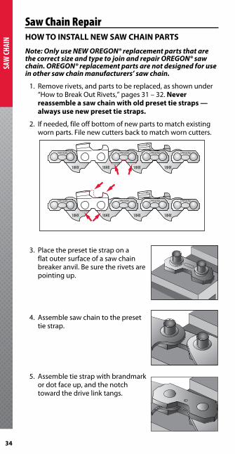
Note: Only use NEW OREGON® replacement parts that are the correct size and type to join and repair OREGON® saw chain. OREGON® replacement parts are not designed for use in other saw chain manufacturers’ saw chain.
1 . Remove rivets, and parts to be replaced, as shown under “How to Break Out Rivets,” pages 31 – 32 . Never reassemble a saw chain with old preset tie straps — always use new preset tie straps .
2 . If needed, file off bottom of new parts to match existing worn parts . File new cutters back to match worn cutters .
3 . Place the preset tie strap on a flat outer surface of a saw chain breaker anvil . Be sure the rivets are pointing up .
4 . Assemble saw chain to the preset tie strap .
5 . Assemble tie strap with brandmark or dot face up, and the notch toward the drive link tangs .
18HX 18HX 18HX 18HX
18HX 18HX 18HX 18HX

35
SAW CHAIN
Saw Chain Troubleshooting6 . Be sure parts are assembled in the correct location,
sequence and direction . Check the illustrations on page8.Ifunsure,askyourOREGON®dealer.
7. UseOREGON®24549HeavyDutyRivetSpinner:• .404"-pitchsawchain(16H,18HX,)
use take up handle “A” and anvil “A” . Do not use a hammer to assemble these saw chain types .
• 3/4"-pitchsawchain(11BC,11H)use part number 108724 . You can strike the rivet hub once to set the rivet in the tie strap .
Most harvester saw chain problems are caused by:• Excessivesawchainspeed• Excessivefeedforce• Incorrectsharpening• Lackoflubrication• Incorrectsawchaintension
Here are the things to look for and the corrective actions you should take:
ProblemCuts slow, cuts rough, or won’t hold an edgeLook closely at your saw chain’s cutters, and compare them to the illustrations that follow .
1 . Light abrasive damage on side plates .Cause: Cutters came in contact with light abrasive materials .Symptoms: Very slow cuttingRemedy: File cutters back until all damage is removed .
2 . Severe abrasive damage on side and/or top plates .Cause: Cutters hit or cut material other than wood, such as rock, dirt or sand . This type of damage typically occurs when cutting close to the ground .Symptoms: Saw chain won’t cut or cuts crookedly if damage is to one side of saw chain . Possible guide bar rail damage .Remedy: File cutters back until all damage is removed .

36
SAW
CHAI
N
Saw Chain Troubleshooting
50˚20˚
3 . Too much top plate filing angle .Cause: Excessive top plate angle while filing or grinding .Symptoms: Cutting angle is very sharp, but dulls fast . Cutting action rough and erratic .Remedy: Resharpen cutters while holding file at the correct top plate filing angle for saw chain . Be sure file guide is stamped with saw chain’s correct top plate angle .
50˚20˚
4 . Too little top plate filing angle .Cause: Filed or ground at less than the recommended angle .Symptoms: Slow cutting . Requires extra effort to cut . Possible binding in cut .Remedy: Resharpen cutters while holding file at the correct top plate filing angle for saw chain . Be sure file guide is stamped with saw chain’s correct top plate angle .
50˚20˚
5 . Too much top plate cutting angle .Cause: File held too low or file too small . Grinders: saw chain ground at the wrong top plate cutting angle or using a wrong size grinding wheel .Symptom: Poor stay-sharp . Rapid dulling . Cuts fast for a short time, then dulls .Remedy: File too small or held too low . Resharpen cutters with file of correct size, heldincorrectposition.Usecorrect file guide .
6 . Too little top plate cutting angle .Cause: File held too high or file too large . Grinders: Saw chain ground at wrong top plate cutting angle or using a wrong size grinding wheel .Symptoms: Slow cutting . Requires extra time . Premature wear to saw chain and guide bar rails .Remedy: File too large or held too high . Resharpen cutters with file of correct size, heldincorrectposition.Usecorrect file guide .

37
SAW CHAIN
7 . Too much hook in side plate .Cause: File held too low or file too small . Grinders: Saw chain ground at wrong top-plate cutting angle, grinding wheel too small or grinding too deep into body of cutter .Symptoms: Rough cutting . Saw chain grabs . Cutters dull quickly or won’t hold cutting edge . Top plate breakage and/or saw chain stretch .Remedy: File too small or held too low . Resharpen cutters with file of correct size, heldincorrectposition.Usecorrectfileguide .
8 . Backslope on side plate .Cause: File held too high or file too large . Grinders: Saw chain ground at wrong top plate cutting angle, grinding wheel too large, or grinding wheel not grinding deep enough into body of cutter .Symptoms: Slow cutting . Requires extra time to cut . Premature wear to saw chain and guide bar rails .Remedy: File too large or held too high . Resharpen cutters with file of correct size, heldincorrectposition.Usecorrectfileguide .
9 . Low depth gauges .Cause: Depth gauge never lowered .Symptoms: Rough cutting . Saw chain grabs . Excessive wear to heel of cutters, opposing tie straps, guide bar rails . Top plate breakage and/or saw chain stretch .Remedy: In most cases, cutters cannot be filed back enough to correct for depth gauges that are too low . Replace saw chain .
10 . High depth gauges .Cause: Depth gauges never lowered .Symptoms: Slow cutting . Excessive wear to saw chain and guide bar rails .Remedy: File depth gauges down to their correct height .
Note: See pages 26 – 29 for the proper filing techniques to use when performing the remedies above.
Saw Chain Troubleshooting
38
SAW
CHAI
N
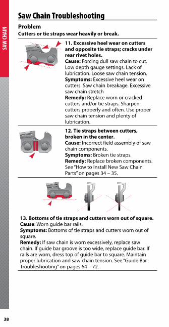
Saw Chain TroubleshootingProblemCutters or tie straps wear heavily or break .
11 . Excessive heel wear on cutters and opposite tie straps; cracks under rear rivet holes .Cause: Forcing dull saw chain to cut . Low depth gauge settings . Lack of lubrication . Loose saw chain tension .Symptoms: Excessive heel wear on cutters . Saw chain breakage . Excessive saw chain stretchRemedy: Replace worn or cracked cutters and/or tie straps . Sharpen cuttersproperlyandoften.Usepropersaw chain tension and plenty of lubrication .
12 . Tie straps between cutters, broken in the center .Cause: Incorrect field assembly of saw chain components .Symptoms: Broken tie straps .Remedy: Replace broken components . See“HowtoInstallNewSawChainParts” on pages 34 – 35 .
13 . Bottoms of tie straps and cutters worn out of square .Cause: Worn guide bar rails .Symptoms: Bottoms of tie straps and cutters worn out of square .Remedy: If saw chain is worn excessively, replace saw chain . If guide bar groove is too wide, replace guide bar . If rails are worn, dress top of guide bar to square . Maintain proper lubrication and saw chain tension . See “Guide Bar Troubleshooting” on pages 64 – 72 .
39
SAW CHAIN
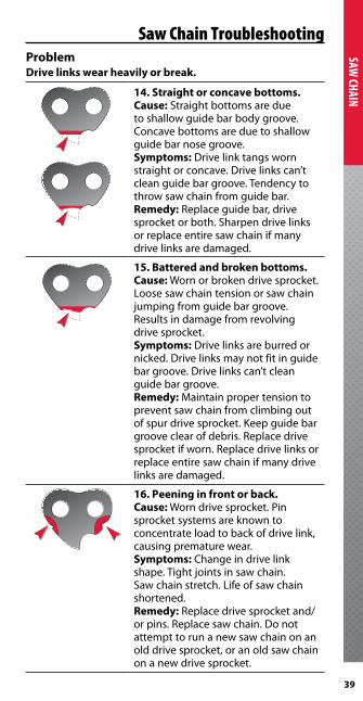
Saw Chain TroubleshootingProblemDrive links wear heavily or break .
14 . Straight or concave bottoms .Cause: Straight bottoms are due to shallow guide bar body groove . Concave bottoms are due to shallow guide bar nose groove .Symptoms: Drive link tangs worn straight or concave . Drive links can’t clean guide bar groove . Tendency to throw saw chain from guide bar .Remedy: Replace guide bar, drive sprocket or both . Sharpen drive links or replace entire saw chain if many drive links are damaged .
15 . Battered and broken bottoms .Cause: Worn or broken drive sprocket . Loose saw chain tension or saw chain jumpingfromguidebargroove.Results in damage from revolving drive sprocket .Symptoms: Drive links are burred or nicked . Drive links may not fit in guide bar groove . Drive links can’t clean guide bar groove .Remedy: Maintain proper tension to prevent saw chain from climbing out of spur drive sprocket . Keepguidebargroove clear of debris . Replace drive sprocket if worn . Replace drive links or replace entire saw chain if many drive links are damaged .
16 . Peening in front or back .Cause: Worn drive sprocket . Pin sprocket systems are known to concentrate load to back of drive link, causing premature wear .Symptoms: Change in drive link shape.Tightjointsinsawchain.Saw chain stretch . Life of saw chain shortened .Remedy: Replace drive sprocket and/or pins . Replace saw chain . Do not attempt to run a new saw chain on an old drive sprocket, or an old saw chain on a new drive sprocket .
40
SAW
CHAI
N
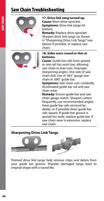
Saw Chain Troubleshooting17 . Drive link tang turned up .Cause: Worn drive sprocket .Symptoms: Drive link tangs hit bottom .Remedy: Replace drive sprocket Sharpen drive link tangs (as shown in “Sharpening Drive Link Tangs” (see below) if possible, or replace saw chain .
18 . Sides worn round or thin at bottoms .Cause: Guide bar rails have spread, or one rail has worn low, allowing saw chain to lean over . Improper sharpening angles . One side of saw chaindull.Useof.063"gaugesawchain in .080" guide bar .Symptoms: Saw chain cuts crookedly . Accelerated guide bar rail and saw chain wear .Remedy: Ensure guide bar and saw chain gauge match . Sharpen cutters frequently, use recommended angles . Have guide bar rails serviced by dealer, or if possible dress guide bar rails square . If guide bar groove is spread too wide, replace guide bar . If saw chain wear is extensive, replace saw chain .
Sharpening Drive Link Tangs
Pointed drive link tangs help remove chips and debris from your guide bar groove . Sharpen damaged tangs back to original shape with a round file .

41
SAW CHAIN
ProblemSaw chain has tight joints .
19 . Peening on bottom or front of cutters and tie straps .Cause: Improper saw chain tension or a worn out drive sprocket .Symptoms: Saw chain stretch or saw chain breakage .Remedy: Sawchainwithtightjointscannot be repaired . Replace the saw chain and maintain proper tension . Replace the rim drive sprocket if worn .
20 . Peening in notches of cutters and tie straps .Cause: Worn spur drive sprocket .Symptoms: Saw chain stretch or saw chain breakage .Remedy: Replace the spur drive sprocket . Replace the saw chain . Always maintain proper tension and do not run saw chain on a worn drive sprocket .
Saw Chain Troubleshooting
42
SAW
CHAI
N ProblemSaw chain cuts crookedly/leans to one side/cuts unevenly
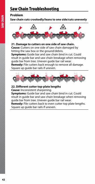
21 . Damage to cutters on one side of saw chain .Cause: Cutters on one side of saw chain damaged by hitting the saw box or the ground/debris .Symptoms: Guide bar and saw chain bind in cut . Could result in guide bar and saw chain breakage when removing guidebarfromtree.Unevenguidebarrailwear.Remedy: File cutters back enough to remove all damage . Square up guide bar rails if uneven .
22 . Different cutter top-plate lengthsCause: Inconsistent sharpening .Symptoms: Guide bar and saw chain bind in cut . Could result in guide bar and saw chain breakage when removing guidebarfromtree.Unevenguidebarrailwear.Remedy: File cutters back to even cutter top plate lengths . Square up guide bar rails if uneven .
Saw Chain Troubleshooting

43
GUIDE BAR
Guide Bar Mounts
.404" GUIDE BAR MOUNTSD104
D104
12
2
Drive sprocket tooth count: 17, 18
Dimensions:
� = .394" x 3 .338"
� = .404" x .555"
L003
1
2
2
2
2
Drive sprocket tooth count: 11, 12, 13
Dimensions:
� = 7/8" ( .875")
� = .448"
L104
L104 .404”
1
2
2
Drive sprocket tooth count: 11, 12, 13
Dimensions:
� = .394" (10mm) x 3 .338"
� = .555" x .404"
GUIDE BAR MOUNT TYPES AND DRIVE SPROCKET TOOTH COUNTS
.404" 3/4"
Guide Bar Mount Type
Drive Sprocket
Tooth Count
Guide Bar Mount Type
Drive Sprocket
Tooth Count
B 13 – 16 C 7
D 17 – 18 E 9
L 11 – 13 F 8 – 9
M 8 – 10 H 21
N 14 – 16 J 8
Y 13 K 7 – 8
P 15
T 9 – 10
V 9 – 10

44
GUID
E BAR
Guide Bar Mounts.404"GUIDEBARMOUNTS,cont.L114
1
2
2 3
3
Drive sprocket tooth count: 11, 12, 13
Dimensions:
� = .394" (10mm) x 3 .338"
� = .555" x .404"
� = .435"
L148
1
2
2 3
3
Drive sprocket tooth count: 11, 12, 13
Dimensions:
� = .394" (10mm) x 3 .338"
� = .555" x .404"
� = .435"
L205
12
1
Drive sprocket tooth count: 11, 12, 13
Dimensions:
� = .555" x .404"
� = .640"
M104
1
2
2
Drive sprocket tooth count: 8, 9, 10
Dimensions:
� = .394" (10mm) x 3 .338"
� = .555" x .404"
M226
12
2
M226 .404”
Drive sprocket tooth count: 8, 9, 10Dimensions:
� = .570" x 3 .914"
� = .311" radius
45
GUIDE BAR
Guide Bar Mounts
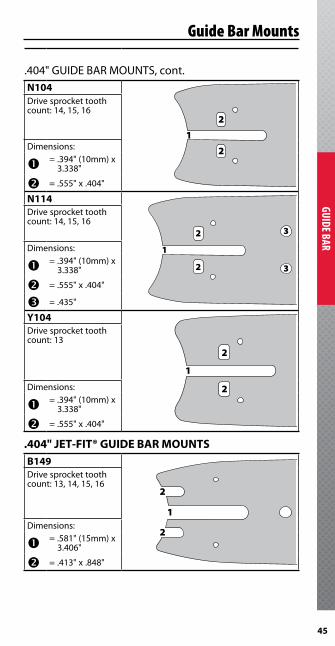
.404"GUIDEBARMOUNTS,cont.N104
1
2
2
Drive sprocket tooth count: 14, 15, 16
Dimensions:
� = .394" (10mm) x 3 .338"
� = .555" x .404"
N114
1
2
2
3
3
Drive sprocket tooth count: 14, 15, 16
Dimensions:
� = .394" (10mm) x 3 .338"
� = .555" x .404"
� = .435"
Y104
1
2
2
Drive sprocket tooth count: 13
Dimensions:
� = .394" (10mm) x 3 .338"
� = .555" x .404"
.404" JET-FIT® GUIDE BAR MOUNTSB149
1
2
2
Drive sprocket tooth count: 13, 14, 15, 16
Dimensions:
� = .581" (15mm) x 3 .406"
� = .413" x .848"
46
GUID
E BAR
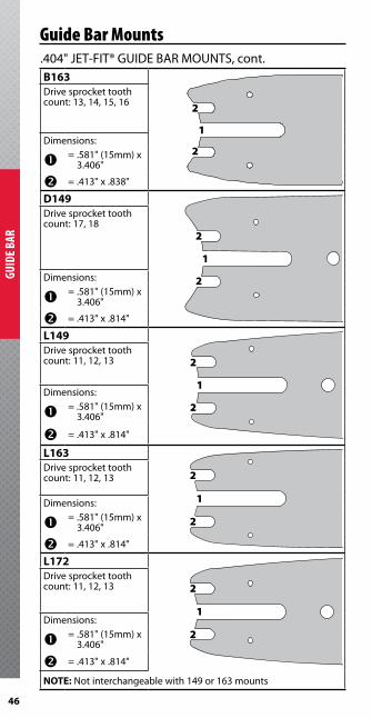
.404"JET-FIT®GUIDEBARMOUNTS,cont.B163
1
2
2
B163 .404” jet �t
Drive sprocket tooth count: 13, 14, 15, 16
Dimensions:
� = .581" (15mm) x 3 .406"
� = .413" x .838"
D149
1
2
2
Drive sprocket tooth count: 17, 18
Dimensions:
� = .581" (15mm) x 3 .406"
� = .413" x .814"
L149
1
2
2
Drive sprocket tooth count: 11, 12, 13
Dimensions:
� = .581" (15mm) x 3 .406"
� = .413" x .814"
L163
1
2
2
Drive sprocket tooth count: 11, 12, 13
Dimensions:
� = .581" (15mm) x 3 .406"
� = .413" x .814"
L172
1
2
2
Drive sprocket tooth count: 11, 12, 13
Dimensions:
� = .581" (15mm) x 3 .406"
� = .413" x .814"
NOTE:Notinterchangeablewith149or163mounts
Guide Bar Mounts
47
GUIDE BAR
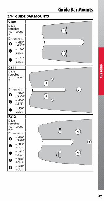
Guide Bar Mounts3/4" GUIDE BAR MOUNTSC159
1
2
23
3
Drive sprocket tooth count: 7Dimensions:
� = .635" x 4 .502"
� = .190" radius
� = .151" radius
C211
C211 3/4”
1
2
2
3
Drive sprocket tooth count: 7
Dimensions:
� = .394" x 3 .338"
� = .404" x .555"
� = .500" radius
F212
F212 3/4”
1
2
3
4
4
5
Drive sprocket tooth count: 8, 9Dimensions:
� = .640" x 3 .640"
� = .313" radius
� = .313" x .867"
� = .648" radius
� = .500" radius
48
GUID
E BAR
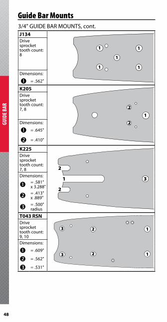
Guide Bar Mounts3/4"GUIDEBARMOUNTS,cont.J134
1
1
1
1
1
Drive sprocket tooth count: 8
Dimensions:
� = .562"
K205
1
2
2
Drive sprocket tooth count: 7, 8
Dimensions:
� = .645"
� = .410"
K225
1 3
2
2
K225 3/4”
Drive sprocket tooth count: 7, 8Dimensions:
� = .581" x 3 .288"
� = .413" x .889"
� = .500" radius
T043 RSN
1
1
3
3
2
2
Drive sprocket tooth count: 9, 10Dimensions:
� = .609"
� = .562"
� = .531"
49
GUIDE BAR
Guide Bar Mounts3/4"GUIDEBARMOUNTS,cont.
T130
1
2
2
Drive sprocket tooth count: 9, 10
Dimensions:
� = .875" x 4 .054"
� = .531" x 3"
T132
1
1
1
1
2
Drive sprocket tooth count: 9, 10
Dimensions:
� = .531" x 3 .064"
� = .562"
T133
1
2
2
Drive sprocket tooth count: 9, 10
Dimensions:
� = .515" x 4 .129"
� = .515"
50
GUID
E BAR
3/4"GUIDEBARMOUNTS,cont.T138
1
2
2
Drive sprocket tooth count: 9, 10
Dimensions:
� = .635" x 7 .410"
� = .650"
T145
1
1
1
1
Drive sprocket tooth count: 9, 10
Dimensions:
� = .570"
T146
1
2
2
2
2
Drive sprocket tooth count: 9, 10
Dimensions:
� = .637" x 3 .627"
� = .531"
T151
1
2
2
Drive sprocket tooth count: 9, 10
Dimensions:
� = .535" x 3 .226"
� = .531"
Guide Bar Mounts
51
GUIDE BAR
Guide Bar Mounts3/4"GUIDEBARMOUNTS,cont.
T152
1
23
3 2
Drive sprocket tooth count: 9, 10
Dimensions:
� = .760" x 5 .910"
� = .562"
� = .531"
T161
1
3
3
2
Drive sprocket tooth count: 9, 10Dimensions:
� = .447" x 5 .500"
� = .880" x .568"
� = .531" x 2 .281"
T168
1
1
2
2
Drive sprocket tooth count: 9, 10
Dimensions:
� = .609"
� = .562"
T190
1
2
2
Drive sprocket tooth count: 9, 10
Dimensions:
� = .760" x 5 .25"
� = .760"

52
GUID
E BAR
3/4"GUIDEBARMOUNTS,cont.T208
1 2
3
3
T208 3/4”
Drive sprocket tooth count: 9, 10
Dimensions:
� = .515" x 4 .129"
� = .500"
� = .770"
T210
1
2
2
2
2
T210 3/4”
Drive sprocket tooth count: 9, 10Dimensions:
� = .500"
� = .782"
T217
1
2
2
2
2
3
T217
Drive sprocket tooth count: 9, 10Dimensions:
� = .787" x 4 .330"
� = .512"
� = .500"
T219
1
2
2
3
T219 3/4”
Drive sprocket tooth count: 9, 10Dimensions:
� = .635" x 3 .312"
� = .380" radius x .302" radius x .620"
� = .500"
Guide Bar Mounts

53
GUIDE BAR
Guide Bar Mounts3/4"GUIDEBARMOUNTS,cont.
T221
1 2
3
3
T221 3/4”
Drive sprocket tooth count: 9, 10
Dimensions:
� = .760" x 4 .374"
� = .500"
� = .760"
T222
1 2
2
2
2
T222 3/4”
Drive sprocket tooth count: 9, 10
Dimensions:
� = .500"
� = .679"
T223
1
2
2
2
2
2
2
T223 3/4”
Drive sprocket tooth count: 9, 10
Dimensions:
� = .500"
� = .679"
T227
1
23
2
T227 3/4”
Drive sprocket tooth count: 9, 10Dimensions:
� = .875" x 4 .000"
� = .500" x 1 .196"
� = .500"

54
GUID
E BAR
3/4"GUIDEBARMOUNTS,cont.
T229
12
3
2
T229 3/4"
Drive sprocket tooth count: 9, 10Dimensions:
� = .880" x 7 .584"
� = .506" x 2 .842"
� = .500"
T230
1
2 3
32
T230 3/4”
Drive sprocket tooth count: 9, 10
Dimensions:
� = .500"
� = .562"
� = .609"
V127
1
1
2
3
2
Drive sprocket tooth count: 9, 10Dimensions:
� = .812" x 2 .577"
� = .812" x 2 .453"
� = .500"
Guide Bar Mounts

55
GUIDE BAR
Guide Bar MountsSYMMETRICAL TWO-ENDED GUIDE BAR MOUNTS9135
1
2
3
3
2
Drive sprocket tooth count: 9, 10
Dimensions:
1
2
3
3
2
� = .906" x 4 .500"
� = .531" x 3 .000"
� = .375"
9136
1
1
1 1
Drive sprocket tooth count: 9, 10
Dimensions:
1
1
1 1� = .516"
9137
1 2
3
34
4
1
Drive sprocket tooth count: 9, 10
Dimensions:
1 2
3
34
4
1
� = .687"
� = .553"
� = .512"
� = .384"
56
GUID
E BAR
SYMMETRICALTWO-ENDEDGUIDEBARMOUNTS,cont.
9164
1 1 1 1
1
1
Drive sprocket tooth count: 9, 10
Dimensions:
1 1 1 1
1
1
� = .531"
E214
E214 3/4” Asymetrical
1
1
1 1
Drive sprocket tooth count: 9, 10
Dimensions:
E214 3/4” Asymetrical
1
1
1 1� = .781"
3/4" ASYMMETRICAL DOUBLE-ENDED MOUNTS9155
1 1
1 1
2
2
2
Drive sprocket tooth count: 15Sprocket end dimension:
� = 4 at .656"
Idler end dimension:
� = 3 at .531"
Guide Bar Mounts

57
GUIDE BAR
Guide Bar Mounts3/4"ASYMMETRICALDOUBLE-ENDED GUIDEBARMOUNTS,cont.9191
1
1 1
12
2
2
Drive sprocket tooth count: 14Sprocket end dimension:
� = 4 at .760"
Idler end dimension:
� = 3 at .531"
H175
1
1
2
2
2
1
3
33 3
Drive sprocket tooth count: 21Sprocket end dimension:
� = 3 at .656"
� = 3 at .531"
Idler end dimension:
� = 4 at .531"
P207
P207
2
2
21
1 1
1
P207
2
2
21
1 1
1
Drive sprocket tooth count: 15Sprocket end dimension:
� = 4 at .781"
Idler end dimension:
� = 3 at .531"

58
GUID
E BAR
OREGON® Guide Bar MaintenanceFor proper mounting of your guide bar, refer to the operator’s manual for your harvesting equipment .
Basic Guide Bar Maintenance Tasks
s Before each use ● Daily
■ Often (Hourly, or at refueling) u Weekly, periodically
1 . s ■ Saw chain tensioning
2 . ● Clean guide bar groove
3 . u Clean oil holes
Oil hole
4 . u Dress the rail . NOTE: Note: If using a grinding wheel, direct debris towards tail, then clean out grooves . Grinding debris can cause the nose components to wear quickly or jam .
OREGON® Bar Rail Dresser, p/n 111589 makes it easy to remove effects of normal wear and remove minor damage .
59
GUIDE BAR
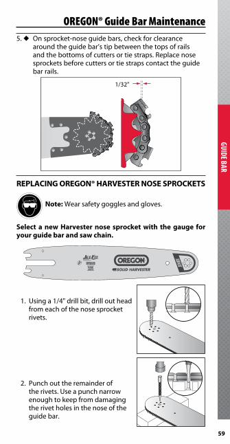
OREGON® Guide Bar Maintenance5 . u On sprocket-nose guide bars, check for clearance
around the guide bar’s tip between the tops of rails and the bottoms of cutters or tie straps . Replace nose sprockets before cutters or tie straps contact the guide bar rails .
1/32"( 0,8 mm )
REPLACING OREGON® HARVESTER NOSE SPROCKETS
Note: Wear safety goggles and gloves .
Select a new Harvester nose sprocket with the gauge for your guide bar and saw chain .
1. Usinga1/4"drillbit,drilloutheadfrom each of the nose sprocket rivets .
2 . Punch out the remainder of therivets.Useapunchnarrowenough to keep from damaging the rivet holes in the nose of the guide bar .
1/32"
60
GUID
E BAR
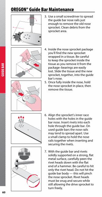
3. Useasmallscrewdrivertospreadtheguidebarnoserailsjustenough to remove the old nose sprocket . Clean debris from the sprocket area .
4 . Inside the nose sprocket package you’ll find the new sprocket wrapped in a tissue . Be careful to keep the sprocket inside the tissue as you remove it from the package–bearings are easily lost . Slide the tissue and the new sprocket, together, into the guide bar’s nose .
5 . Once fully inside the nose, hold the nose sprocket in place, then remove the tissue .
6 . Align the sprocket’s inner race holes with the holes in the guide bar nose . Insert rivets into each hole through the guide bar . On used guide bars the nose rails maytendtospreadapart.Usea small clamp to hold the nose rails together when inserting and securing the rivets .
7 . With the guide bar and rivets solidly supported on a strong, flat metal surface, carefully peen the rivet heads down with the flat end of a hammer . Be careful to hit only the rivet head . Do not hit the guide bar body — this will pinch the nose sprocket . Rivet heads must be snug and secure while still allowing the drive sprocket to turn freely .
OREGON® Guide Bar Maintenance

61
GUIDE BAR
OREGON® Guide Bar MaintenanceREPLACING OREGON® HARVESTER NOSE SPROCKETS WITH REPLACEMENT NOSE KITS
1. UsingtheOREGON®heavy-dutychain breaker #24548, break out the bar tip attachment rivets .
2 . Break out the remaining rivets . Useapunchnarrowenoughtokeep from damaging the rivet holes in the nose of the guide bar .
3 . Remove the old nose . Clean the guide bar’s attachment area . Insert the rivets through the underside of the nose .
4 . With the guide bar body, nose, and rivet solidly supported on a strong flat metal surface, peen the rivet’s head down with the flat end of a hammer . Do not hit the guide bar body, hit only the rivet head . To check installation, grip the guide bar body in onehand,andtwist.Noseand body should feel like a single, solid piece . If not (if any movement in the noseguidebarjointareaisfelt, or if any clicking sound from the same area is heard), tighten the rivet with a few more hammer strokes .
5 . File down the rails of the new nose to align with the rails of the old guide bar body .
62
GUID
E BAR
OREGON® Guide Bar MaintenanceSTRAIGHTENING OREGON® HARVESTER GUIDE BARS
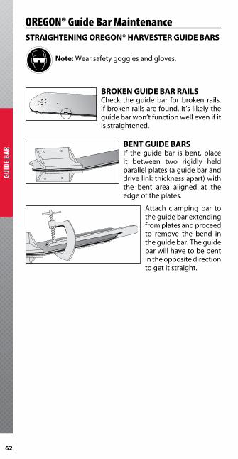
Note: Wear safety goggles and gloves .
BROKEN GUIDE BAR RAILSCheck the guide bar for broken rails . If broken rails are found, it’s likely the guide bar won’t function well even if it is straightened .
BENT GUIDE BARSIf the guide bar is bent, place it between two rigidly held parallel plates (a guide bar and drive link thickness apart) with the bent area aligned at the edge of the plates .
Attach clamping bar to the guide bar extending from plates and proceed to remove the bend in the guide bar . The guide bar will have to be bent in the opposite direction to get it straight .

63
GUIDE BAR
OREGON® Guide Bar MaintenanceTWISTED GUIDE BARSSight down the guide bar to identify which way it’s twisted .
Place the guide bar between the plates so that the twisted section justprotrudesform the plates .
Place the clamping bar across the guide bar six inches from the opening on the side of the plates and torque the clamping bar in the opposite direction of the twist . Proceed along the guide bar in six-inch increments until the twist is removed .
Remove the guide bar from the bar straightening tool and place it on a hard working surface . Insert a piece of metal (the same width as the guide bar groove) where the guide bar was bent . Hammer any small kinks out of the bent section . Take care to keep the groove width tool in place so the rails cannot be hammered shut . Hammer the guide bar with the cupped side down .
Slide cutting saw chain into the guide bar groove . Make sure that there are no pinch points between the rails .
Open up the rails with a screw driver at pinch points .
64
GUID
E BAR
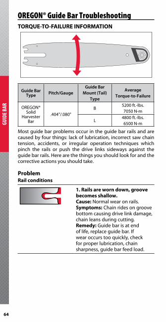
OREGON® Guide Bar TroubleshootingTORQUE-TO-FAILURE INFORMATION
Most guide bar problems occur in the guide bar rails and are caused by four things: lack of lubrication, incorrect saw chain tension, accidents, or irregular operation techniques which pinch the rails or push the drive links sideways against the guide bar rails . Here are the things you should look for and the corrective actions you should take .
ProblemRail conditions
1 . Rails are worn down, groove becomes shallow .Cause:Normalwearonrails.Symptoms: Chain rides on groove bottom causing drive link damage, chain leans during cutting .Remedy: Guide bar is at end of life, replace guide bar . If wear occurs too quickly, check for proper lubrication, chain sharpness, guide bar feed load .
Guide Bar Type Pitch/Gauge
Guide Bar Mount (Tail)
Type
Average Torque-to-Failure
OREGON®Solid
Harvester Bar
.404"/ .080"B
5200 ft .-lbs .7050N-m
L4800 ft .-lbs .6500N-m

65
GUIDE BAR
2 . Outside edge of rails develop wire edges .Cause:Normalwearonrails.Symptoms: Left alone, wire edges can break off and chip away rail material .Remedy:Useflatfileorgrinderto square up guide bar’s rails and remove wire edges . If wire edges develop too quickly, check for proper lubrication, saw chain sharpness and guide bar feed load .Note: If using a grinding wheel, direct debris towards tail, then clean out grooves. Grinding debris can cause nose components to wear quickly or jam.
3 . Rail on one side is worn thin .Cause: Damaged or dull cutters on one side (see saw chain section) . Saw chain leaning over in a worn groove or using a .063" gauge saw chain in a .080" gauge guide bar .Symptoms: Incomplete cuts, leading cuts, guide bar bound in the cut .Remedy: Replace guide bar, check for correct saw chain gauge, replace saw chain if it continues to cut crooked after sharpening (see Saw Chain section) .
4 . Rails around tip of solid-nose guide bars show small cracks or broken-out sections .Cause: Accidents or irregular operating techniques which push drive links sideways or place excessive pressure on side of nose can cause breaks or cracks .Symptoms: Damage to tie straps and cutters, saw chain throws, short guide bar life .Remedy: Your dealer may be able to repair minor damage on a relatively new guide bar .
OREGON® Guide Bar Troubleshooting

66
GUID
E BAR
5 . Rails around the tip of solid-nose guide bars are split at the bottom of the guide bar groove .Cause: Accidents or irregular operating techniques which push drive links sideways or place excessive pressure on side of nose can cause breaks or cracks .Symptoms: Rails spread and chain rides on groove bottom causing drive link damage and saw chain leans during cutting .Remedy: Your dealer may be able to repair minor damage on a relatively new guide bar .
6 . Rails along the guide bar body or around the tip of sprocket nose guide bars show blue discoloration .Cause: Pinched rails, lack of lubrication, or accidents and cutting techniques which can push drive links sideways in the groove creating extreme friction-generated heat .Symptoms: Blue spots on rails indicate temperatures reaching 600° F (315° C) and rail softening . Rails wear quickly . Saw chain drive link damage .Remedy: Replace guide bar and saw chain .
OREGON® Guide Bar Troubleshooting
67
GUIDE BAR
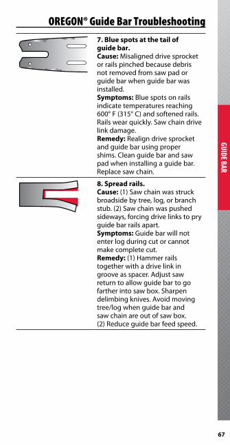
OREGON® Guide Bar Troubleshooting7 . Blue spots at the tail of guide bar .Cause: Misaligned drive sprocket or rails pinched because debris not removed from saw pad or guide bar when guide bar was installed .Symptoms: Blue spots on rails indicate temperatures reaching 600° F (315° C) and softened rails . Rails wear quickly . Saw chain drive link damage .Remedy: Realign drive sprocket and guide bar using proper shims . Clean guide bar and saw pad when installing a guide bar . Replace saw chain .
8 . Spread rails .Cause: (1) Saw chain was struck broadside by tree, log, or branch stub . (2) Saw chain was pushed sideways, forcing drive links to pry guide bar rails apart .Symptoms: Guide bar will not enter log during cut or cannot make complete cut .Remedy: (1) Hammer rails together with a drive link in grooveasspacer.Adjustsawreturn to allow guide bar to go farther into saw box . Sharpen delimbing knives . Avoid moving tree/log when guide bar and saw chain are out of saw box . (2) Reduce guide bar feed speed .
68
GUID
E BAR
OREGON® Guide Bar Troubleshooting
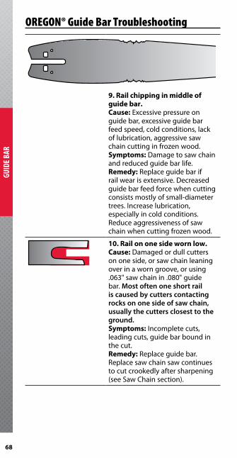
9 . Rail chipping in middle of guide bar .Cause: Excessive pressure on guide bar, excessive guide bar feed speed, cold conditions, lack of lubrication, aggressive saw chain cutting in frozen wood .Symptoms: Damage to saw chain and reduced guide bar life .Remedy: Replace guide bar if rail wear is extensive . Decreased guide bar feed force when cutting consists mostly of small-diameter trees . Increase lubrication, especially in cold conditions . Reduce aggressiveness of saw chain when cutting frozen wood .
10 . Rail on one side worn low .Cause: Damaged or dull cutters on one side, or saw chain leaning over in a worn groove, or using .063" saw chain in .080" guide bar . Most often one short rail is caused by cutters contacting rocks on one side of saw chain, usually the cutters closest to the ground.Symptoms: Incomplete cuts, leading cuts, guide bar bound in the cut .Remedy: Replace guide bar . Replace saw chain saw continues to cut crookedly after sharpening (see Saw Chain section) .
69
GUIDE BAR
OREGON® Guide Bar TroubleshootingProblemGuide Bar Nose Failures
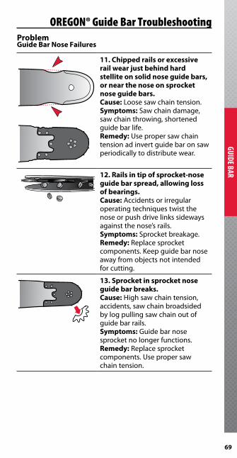
11 . Chipped rails or excessive rail wear just behind hard stellite on solid nose guide bars, or near the nose on sprocket nose guide bars .Cause: Loose saw chain tension .Symptoms: Saw chain damage, saw chain throwing, shortened guide bar life .Remedy:Usepropersawchaintension ad invert guide bar on saw periodically to distribute wear .
12 . Rails in tip of sprocket-nose guide bar spread, allowing loss of bearings .Cause: Accidents or irregular operating techniques twist the nose or push drive links sideways against the nose’s rails .Symptoms: Sprocket breakage .Remedy: Replace sprocket components.Keepguidebarnoseawayfromobjectsnotintendedfor cutting .
13 . Sprocket in sprocket nose guide bar breaks .Cause: High saw chain tension, accidents, saw chain broadsided by log pulling saw chain out of guide bar rails .Symptoms: Guide bar nose sprocket no longer functions .Remedy: Replace sprocket components.Usepropersawchain tension .

70
GUID
E BAR
OREGON® Guide Bar Troubleshooting14 . Nose burned at tip from saw chain sliding on rails of sprocket nose guide bar, or from the sprocket being recessed into the tip .Cause: High saw chain tension from automatic saw chain tensioners .Symptoms:Nosebreakagefrombearings wearing quickly and jamming.Remedy: Decrease the tension applied by automatic saw chain tensioner .
15 . Loose or missing nose/attachment rivets .Cause: Guide bar tip flexing during operation from difficult cutting conditions, accidents .Symptoms: Rivets continue to loosen until laminates spread and bearings are lost .Remedy: Check rivets every 100 machine hours . Rehammer loose rivets and replace rivets if rivet head is missing . Always use new rivets .
16 . Burn ring around nose rivets .Cause: Bearings overheated .Symptoms: Premature breakage, jamming,wearingofsprocketnose components .Remedy: Check for proper oil flow rates . Saw chips will plug oil line or guide bar oil hole . Clean out guide bar oil hole daily Install wire mesh screen on oil tank filler spout to prevent chips from getting into tank .

71
DRIVE SPROCKET
17 . Tabs on replaceable nose sprocket (RSN) break off .Cause: Accidental bending of nose .Symptoms:RSNnolongerfunctions .Remedy:InstallnewRSN.AvoidbendingRSN.
ProblemGuide Bar Mount Failures
18 . Spread or broken guide bar mounting slot .Cause: Holding pins/bolts were not inserted into guide bar mount holes . Guide bar is not properly supported when minor accidents or pinches occur .Symptoms: Guide bar mount slot spreads or guide bar breaks at the slot prematurely . If Jet-Fit guide bar fails from tip of middle slot to side as shown without small tab also breaking, then pins are missing or broken off.Remedy: Replace broken guide bars and use the holding pins/bolts originally supplied with guide bar holder . When purchasing new harvester head, consider purchasing headcompatiblewithOREGON®Jet-Fit®guidebars.
OREGON® Guide Bar Troubleshooting

72
GUID
E BAR
ProblemJet -Fit® Guide Bar Mount Failures
19 . Chronic or frequent guide bar mount breakage on Jet-Fit® guide bars when no accident has occurred .Cause: (1) Guide bar retraction speed too fast . (2) Forward guide bar-sweep speed too fast, causing guide bar holder to stop quickly at end of its rotation .In either case, inertia of guide bar causes it to over-rotate in the guide bar mount, putting excessive stress on the guide bar mount .Symptoms: (1) Guide bar breakage without guide bar being involved in accident.(2)Unexplainedguidebarmount breakage .Remedy: Reduce pressure, or flow, to cylinder that sweeps guide bar forward, out of saw box, or retracts guide back into the saw box .
20 . Occasional failure of Jet-Fit® guide bars when accidents occur .Cause: Guide bar becomes stuck in the cut, or accident occurs causing guide bar to become stuck .Symptoms: Force required to dislodge guide bar approaches strength of guide bar holder, during which guide bar mount breaks .Remedy:Inthiscase,Jet-Fit®guidebar breaks as designed to prevent damage to expensive guide bar mount shown in the illustration below .
GuideBar
GuideBar
MountÆ
OREGON® Guide Bar Troubleshooting

73
DRIVE SPROCKET
OREGON® Drive SprocketsYour drive sprocket is an integral component of your “cutting system,” transferring the power from your harvester to your saw chain to drive it around your guide bar . Your drive sprocket, saw chain and guide bar work as a team, they will wear as a team, and should be inspected and maintained as a team .
Type Advantages Disadvantages
SPUR • Nosawchainalignment problem unless drive sprocket is worn .
• Lessexpensive.
• Nosidesupport.• Damagessawchain
if thrown .
RIM • Bestsawchainsupport for cutters and tie straps .
• Needstoalignwithguide bar .*
*Check the alignment of your rim drive sprocketregularlyanduseshimstoadjustthe rim’s position into correct alignment . See page 74 for more information on drive sprocket alignment .
RIMHarvesterLok™
• Uniformpressureeliminates distortion, warping
• Fittingsforsmaller shafts .
• Keylesshub• Hex-headset
screws for quick installation, adjustmentandremoval in the field .
• Nospacebetween drive sprocket and shaft gives zero backlash .
• Drivesprocketmustbe aligned to drive shaft to prevent damage to saw chain, guide bar and drive sprocket .
PIN • Replaceablepins. • Concentratesloadson back of drive link .
• Maycausedrivelink chipping .

74
DRIV
E SPR
OCKE
T
COMMON DRIVE SHAFT CONFIGURATIONS - .404"
DRIVE SPROCKET ALIGNMENTTo prevent damage to the guide bar, saw chain and drive shaft, the drive sprocket must be aligned with the guide bar’s groove .
We recommend using the OREGON® Multi-Purpose Tool &Stretch Gauge, available in both 3/4" and .404" pitch . This handy tool is a beneficial assistant to any logger performing many common maintenance tasks, not just drive sprocketalignment .
533700 3/4" pitch Harvester Multi-Purpose Tool
533689 .404" pitch Harvester Multi-Purpose Tool
1 . Mount guide bar on harvester’s head .2. UsetheOREGON®Multi-PurposeToolthatmatchesyour
saw chain pitch .3 . Place the Multi-Purpose Tool in the guide bar’s groove
and slide it back until it extends to the drive sprocket .
TYPE A TYPE B
Ø 1.010" 25.85 mm
Ø .880" 22.35 mm
Ø .788" 20.015 mm
1.181" 30 mm
.236" 5.99 mm
2X Ø .242" 6.15 mm
TYPE C
2X .974" 24.74 mm
.250" 6.35 mm
.315" 8 mm
4X Ø .242" 6.15 mm
Ø .985" 25.019 mm
OREGON® Drive Sprockets
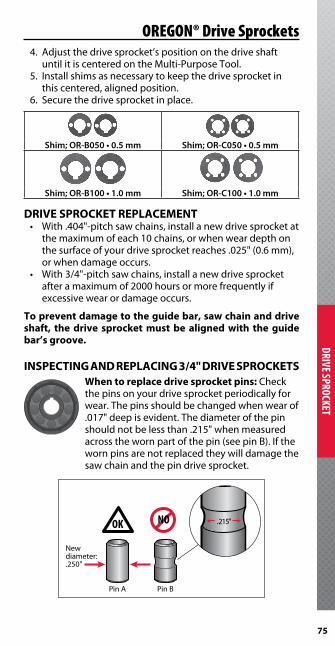
75
DRIVE SPROCKET
OREGON® Drive Sprockets4. Adjustthedrivesprocket’spositiononthedriveshaft
until it is centered on the Multi-Purpose Tool .5 . Install shims as necessary to keep the drive sprocket in
this centered, aligned position .6 . Secure the drive sprocket in place .
DRIVE SPROCKET REPLACEMENT• With.404"-pitchsawchains,installanewdrivesprocketat
the maximum of each 10 chains, or when wear depth on the surface of your drive sprocket reaches .025" (0 .6 mm), or when damage occurs .
• With3/4"-pitchsawchains,installanewdrivesprocketafter a maximum of 2000 hours or more frequently if excessive wear or damage occurs .
To prevent damage to the guide bar, saw chain and drive shaft, the drive sprocket must be aligned with the guide bar’s groove .
INSPECTING AND REPLACING 3/4" DRIVE SPROCKETSWhen to replace drive sprocket pins: Check the pins on your drive sprocket periodically for wear . The pins should be changed when wear of .017" deep is evident . The diameter of the pin should not be less than .215" when measured across the worn part of the pin (see pin B) . If the worn pins are not replaced they will damage the saw chain and the pin drive sprocket .
Shim; OR-B050 • 0.5 mm Shim; OR-C050 • 0.5 mm
Shim; OR-B100 • 1.0 mm Shim; OR-C100 • 1.0 mm
NO
Newdiameter:.250"
OK
Pin A Pin B
.215"

76
DRIV
E SPR
OCKE
T
When to replace spur drive sprockets: Spur drive sprockets should be replaced when wear depth reaches .025" on the spur teeth.Usinganoverlyworndrivesprocketwill cause damage to the saw chain chassis, including tie strap burrs and peened drive links; these can lead to saw chain breakage .
When to replace rim drive and HarvesterLok™ rim drive sprockets: Rim drive sprockets should be replaced when wear depth reaches .025" on the rim surface, or when the rim drive sprocket’s tooth tips are worn below the drive sprocket’s outer diameter(therimsurface).Usinganoverlyworn drive sprocket will cause damage to the saw chain chassis, including tie strap burrs and peened drive links; these can lead to saw chain breakage .
OREGON® Drive Sprockets

77
DRIVE SPROCKET
OREGON® Drive SprocketsDRIVE SPROCKET TROUBLESHOOTINGYour drive sprocket, the third member of the cutting team, deserves regular attention and maintenance just like yourguide bar and saw chain . A misused drive sprocket can cause unnecessary patterns of saw chain wear, which can damage the guide bar and reduce the life of all three components . A damaged drive sprocket cannot be repaired, it can only be inspected and replaced .
NOTE:Anewsawchaincanbe ruined if installedonawornrim or spur drive sprocket . Check the wear on your rim drive sprocket or spur drive sprocket daily, and before each session of use . If worn, replace the drive sprocket before installing a new saw chain . In abrasive conditions, wear will increase . Here are the things you should look for, and the corrective actions you should take .
Problem1 . Worn rim drive sprocketCause:Usebeyondservicelifecausing excessive wear on outer and inner surfaces of rim drive sprocket .Symptoms: Saw chain breakage . Drive link wear, breakage .Remedy: Replace rim drive sprocket
2 . Worn spur drive sprocketCause:Usebeyondservicelifecausing excessive wear on tips of drive sprocket teeth, and between teeth .Symptoms: Saw chain breakage . Drive link wear, breakage .Remedy: Replace spur drive sprocket .
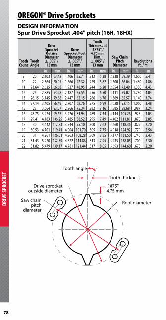
78
DRIV
E SPR
OCKE
T
OREGON® Drive SprocketsDESIGN INFORMATIONSpur Drive Sprocket .404" pitch (16H, 18HX)
Tooth Count
Tooth Angle
Drive Sprocket Outside
Diameter ± .005" /
13 mm
Drive Sprocket Root
Diameter ± .005" /
13 mm
Tooth Thickness at
.1875" /4.75 mm
Dim. ± .005" /
13 mm
Saw Chain Pitch
DiameterRevolutions
ft. / m in. mm in. mm in. mm in. mm ft. m
9 20 2.103 53.42 1.406 35.71 .212 5.38 2.338 59.39 1.650 5.4110 22 2.364 60.05 1.666 42.32 .229 5.82 2.600 66.04 1.480 4.8611 23.64 2.625 66.68 1.927 48.95 .244 6.20 2.854 72.49 1.350 4.4312 25 2.885 73.28 2.187 55.55 .256 6.50 3.111 79.02 1.230 4.0413 26.15 3.145 79.88 2.447 62.15 .266 6.76 3.369 85.57 1.140 3.7414 27.14 3.405 86.49 2.707 68.76 .275 6.99 3.628 92.15 1.060 3.4815 28 3.664 93.07 2.966 75.34 .282 7.16 3.885 98.68 .987 3.2416 28.75 3.924 99.67 3.226 81.94 .289 7.34 4.144 105.26 .925 3.0317 29.41 4.183 106.25 3.485 88.52 .295 7.49 4.402 111.81 .870 2.8518 30 4.442 112.83 3.744 95.10 .300 7.62 4.660 118.36 .822 2.7019 30.53 4.701 119.41 4.004 101.70 .305 7.75 4.918 124.92 .779 2.5620 31 4.961 126.01 4.263 108.28 .309 7.85 5.177 131.50 .740 2.4321 31.43 5.220 132.59 4.522 114.86 .313 7.95 5.435 138.05 .700 2.3022 31.82 5.479 139.17 4.781 121.44 .317 8.05 5.693 144.60 .670 2.20
Tooth angle
Saw chainpitch
diameter
Drive sprocketoutside diameter
Tooth thickness
Root diameter
.1875"4.75 mm

79
DRIVE SPROCKET
79
OREGON® Drive SprocketsDESIGN INFORMATIONSpur Drive Sprocket 3/4" pitch (11BC, 11H)
Tooth angle
Saw chainpitch
diameter
Drive sprocketoutside diameter
Tooth thickness
Root diameter
.1875"4.75 mm
Tooth Count
Tooth Angle
Sprocket Outside
Diameter ± .005" /
13 mm
Drive Sprocket Root
Diameter ± .005" /
13 mm
Tooth Thickness at
.1875" /4.75 mm
Dim. ± .005" /
13 mm
Saw Chain Pitch
DiameterRevolutions
ft. / m in. mm in. mm in. mm in. mm ft. m
7 19.29 3.120 79.25 2.065 52.45 .303 7.70 3.544 90.62 1.100 3.618 22.5 3.627 92.13 2.571 65.30 .331 8.41 4.036 102.51 .959 3.159 25 4.131 104.93 3.036 77.11 .353 8.97 4.532 115.11 .852 2.80
10 27 4.635 117.73 3.539 89.89 .370 9.40 5.027 127.69 .767 2.5211 28.64 5.137 130.48 4.042 102.67 .383 9.73 5.522 140.26 .697 2.2912 30 5.639 143,23 4.543 115.39 .394 10.01 6.018 152.86 .639 2.1013 31.15 6.141 155.98 5.045 128.14 .403 10.24 6.516 165.51 .590 1.9414 32.14 6.642 168.71 5.546 140.87 .411 10.44 7.012 178.10 .548 1.8015 33 7.142 181.41 6.047 153.59 .418 10.62 7.509 190.73 .511 1.6816 33.75 7.643 194.13 6.547 166.29 .424 10.77 8.007 203.38 .479 1.5717 34.41 8.143 206.83 7.047 178.99 .429 10.90 8.504 216.00 .451 1.4818 35 8.643 219.53 7.548 191.72 .430 10.92 9.001 228.63 .436 1.4319 35.53 9.143 232.23 8.048 204.42 .437 11.10 9.499 241.27 .404 1.3320 36 9.643 244.93 8.547 217.09 .441 11.20 9.997 253.92 .384 1.2621 36.43 10.142 257.63 9.047 229.79 .444 11.28 10.495 266.57 .365 1.2022 36.82 10.643 270.33 9.547 242.49 .447 11.35 10.994 279.25 .349 1.14

80
DRIV
E SPR
OCKE
T
OREGON® Drive SprocketsHARVESTERLOK™ INFORMATION
Hub Rim
COMPLETE HARVESTERLOK™ SYSTEMSPART NO . BORE RIM NO . HUB NO .
OR9-HL1-14 7/8" OR9-HL1 HL1-14OR9-HL1-15 15/16" OR9-HL1 HL1-15OR9-HL1-16 1" OR9-HL1 HL1-16OR9-HL1-18 1-1/8" OR9-HL1 HL1-18OR9-HL1-20 1-1/4" OR9-HL1 HL1-20OR9-HL1-30 30 mm OR9-HL1 HL1-30
HARVESTERLOK™ RIMSPART NO . TOOTH COUNTOR9-HL1 9
OR10-HL1 10

81
DRIVE SPROCKET
OREGON® Drive Sprockets
CHAIN CATCHERPART NO . DESCRIPTION
HL1-CC For HL1 Systems
HARVESTERLOK™ HUBSPART NO . BORE
HL1-14 7/8"HL1-15 15/16"HL1-16 1"HL1-18 1-1/8"HL1-20 1-1/4"HL1-30 30 mm
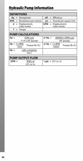
82
DEFINITIONSHp = Horsepower eff. = Efficiency
RPM = Revolutions per minute psi = Pounds per square inchd = Displacement,
cubic inchesGPM = Displacement,
cubic inchesT = Torque
PUMP CALCULATIONSHp = GPM x psi
1714 x eff . (pump)or Hp = .000583 x GPM x psi
eff . (pump)Hp = T x RPM
5252 Torque (lb .-ft .) or Hp = T x RPM
63025 Torque (lb .-ft .)
Hp = volts x amperes745 .7
PUMP OUTPUT FLOWGPM = RPM x d
231 cu . in .1 gal. = 231 cu . in .
Hydraulic Pump Information

83
Harvester Head (Mfg ./Model):
GuideBarPartNumber:
SawChain(PartNumber/Size):
Drive Sprocket (Pitch/Tooth Count):
Notes

84
Notes

This handbook provides information that OREGON® considers critical to the successful and safe use of OREGON® saw chain-based cutting systems in mechanized wood harvesting and processing. In offering this information, Oregon® does not assume any responsibility for the design or manufacture of equipment, nor for the content of literature supplied by equipment manufacturers. This handbook is intended for designers, manufacturers, sellers, and users of saw chain-based cutting systems for mechanized wood harvesting/processor machinery.
The saw chain-based cutting system on a mechanized wood harvesting/processor machinery must meet two fundamental objectives:• Performance (production, reliability, life)• SafetyIn saw chain-based cutting systems, a number of interrelated factors influence the degree of success in both performance and safety. This Oregon® Mechanical Timber Harvesting Handbook is intended to assist you in understanding those factors.
OREGON® HARVESTER CHAIN(Not intended for use on handheld chain saws).404" pitch:16H – Micro Chisel® 18HX – Micro Chisel®
3/4" pitch:11BC – Chipper11H – Semi-Chisel
Introduction
This Timber Harvesting Handbook supersedes and replaces all previous OREGON® Timber Harvesting Handbooks.
Blount, Inc. • ©2012

Mechanical Timber Harvesting HandbookEFFECTIVE JANUARY 1, 2012
OREGON® | Blount, Inc.Corporate HeadquartersP.O. Box 22127Portland, Oregon 97269-2127 USAoregonproducts.com800-223-5168 • 503-653-8881
© Copyright 2012 | Blount, Inc. | F/N A106976 Rev AF 1/12
OREG
ON
® MECH
AN
ICAL TIM
BER H
ARV
ESTING
HA
ND
BOO
K