ti mmwave sensors overview - university of florida
TRANSCRIPT

TI mmWave Sensors IWR14xx/16xx Device Overview

Agenda
• Device Overview
– TI mmWave sensor portfolio
– IWR1xx Signal processing chain
– Example System topologies
• Functional Blocks
– Device Block Diagram
– RF and Analog Subsystem
– Radar Subsystem (aka BSS or BIST Subsystem)
– Master Subsystem (MSS)
– DSP Subsystem (DSS: IWR16xx only)
– Radar Hardware accelerator
• Boot modes
• Software Platform
2

Device Overview
3

mmWave Sensors – 76-81 GHz Portfolio
4
mmWave Sensor + HW Accelerator
• Use Case
– Satellite Sensor with MCU
• 4X IWR14 + Central Processor
• 2X IWR14 + Central Processor
– Entry-level Single-chip Sensor
• Power-optimized applications
• HW acceleration for limited processing
mmWave Sensor + DSP
• Use Cases
– Full functionality single-chip radar
• Increased on-board memory for
higher range and resolution
measurement
• On-chip DSP for advanced
algorithms
IWR1443
4RX Calibration,
Monitoring
Engine
3TX* Synth
R4F
Radar
Acc
576KB
SPI CSI2/
LVDS CAN
IWR1642
4RX Calibration,
Monitoring
Engine
2TX Synth
R4F
C674x
1.5MB
SPI CAN LVDS

Key Features
• FMCW Radar transceiver with 76-81 GHz operating frequency with 4 GHz chirp bandwidth
• MIMO: Up to three transmitter and four receiver chains
• Programmable, flexible chirp profiles for both long and short range sensing in the same radar frame
• 200MHz ARM Cortex R4F MCU for user application processing
• Radar Hardware accelerator for FFT and CFAR processing (14xx only)
• C674x DSP for FMCW signal processing and advanced tracking, clustering and object classification (I16xx only)
• Continuous monitoring and calibration of Analog/RF through a second dedicated Cortex R4F MCU
• CAN support for ECU Interface
• QSPI Serial Flash support for autonomous boot
• MIBSPI, SPI, I2C, and UART Serial Interfaces Support
• CSI2 (IWR14xx only) and LVDS interfaces for high speed raw data transfer
5

IWR1xxx mmWave Signal Processing
6
RF Front-End ADC ADC Data
IWR1443
IWR1642
Pre-
Processing (Interference Mitigation)
1st Dim FFT
(Range)
2nd Dim FFT
(Velocity)
Detection
(CFAR)
3rd Dim FFT
(Angle Arrival)
Point Cloud [Range, Velocity, Angle]
Clustering Tracking Object Classification Objects

Example System Topologies
7
Fluid Level Sensing
MSP432
IWR14xx
SPI
2-Wire, IO-Link, CAN
Transport and Mobile Robots: Front-View and Landing
DM5xx
AM437x
FPGA
IWR16xx
IWR14xx
SPI

Transport and Mobile Robots: Surround Sensing
Example System Topologies
8
DM5xx
AM437x
FPGA
IWR16xx
IWR14xx
IWR16xx
IWR14xx
IWR16xx
IWR14xx
IWR16xx
IWR14xx
SPI SPI
SPI
SPI
Traffic Monitoring
DM8127
IWR16xx
IWR14xx
SPI
Ethernet
Functional Blocks
9

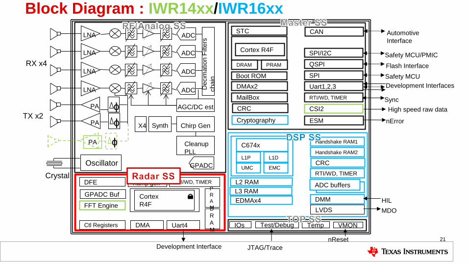
Block Diagram : IWR14xx/IWR16xx
10
LNA
LNA
LNA
LNA
PA
ADC
ADC
ADC
ADC Decim
ation F
ilters
chain
AGC/DC est.
Cleanup
PLL
Synth ᶲ Chirp Gen
Oscillator
Crystal
TX x2
RX x4
PA ᶲ X4
GPADC Buf Cortex
R4F
P
R
A
M D
R
A
M DMA
Ramp gen RTI/WD, TIMER
C674x
L1P
UMC
L1D
EMC
L2 RAM
EDMAx4
Handshake RAM1
Handshake RAM2
ADC buffers ADC buffers
LVDS
CRC
DMM
MDO
Cortex R4F
DRAM PRAM
DMAx2
Automotive
Interface
Boot ROM
STC
MailBox
IOs
JTAG/Trace
nReset
Test/Debug VMON
L3 RAM
HIL
SPI/I2C
QSPI
Safety MCU/PMIC
Flash Interface
nError
RTI/WD, TIMER
CAN
SPI
CSI2
Safety MCU
Sync
ESM
Uart1,2,3
Temp
Cryptography
Development Interfaces
Uart4
Development Interface
Ctl Registers
DFE
FFT Engine
RTI/WD, TIMER
GPADC
CRC High speed raw data
PA ᶲ

Block Diagram : IWR14xx/IWR16xx
11
LNA
LNA
LNA
LNA
PA
ADC
ADC
ADC
ADC Decim
ation F
ilters
chain
AGC/DC est.
Cleanup
PLL
Synth ᶲ Chirp Gen
Oscillator
Crystal
TX x2
RX x4
PA ᶲ X4
GPADC Buf Cortex
R4F
P
R
A
M D
R
A
M DMA
Ramp gen RTI/WD, TIMER
C674x
L1P
UMC
L1D
EMC
L2 RAM
EDMAx4
Handshake RAM1
Handshake RAM2
ADC buffers ADC buffers
LVDS
CRC
DMM
MDO
Cortex R4F
DRAM PRAM
DMAx2
Boot ROM
STC
MailBox
IOs
JTAG/Trace
nReset
Test/Debug VMON
L3 RAM
HIL
SPI/I2C
QSPI
Safety MCU/PMIC
Flash Interface
nError
RTI/WD, TIMER
SPI
CSI2
Safety MCU
Sync
ESM
Uart1,2,3
Temp
Cryptography
Development Interfaces
Uart4
Development Interface
Ctl Registers
DFE
FFT Engine
RTI/WD, TIMER
GPADC
CRC High speed raw data
PA ᶲ
Automotive
Interface
CAN

Block Diagram : IWR14xx/IWR16xx
12
LNA
LNA
LNA
LNA
PA
ADC
ADC
ADC
ADC Decim
ation F
ilters
chain
AGC/DC est.
Cleanup
PLL
Synth ᶲ Chirp Gen
Oscillator
Crystal
TX x2
RX x4
PA ᶲ X4
GPADC Buf Cortex
R4F
P
R
A
M D
R
A
M DMA
Ramp gen RTI/WD, TIMER
C674x
L1P
UMC
L1D
EMC
L2 RAM
EDMAx4
Handshake RAM1
Handshake RAM2
ADC buffers ADC buffers
LVDS
CRC
DMM
MDO
Cortex R4F
DRAM PRAM
DMAx2
Boot ROM
STC
MailBox
IOs
JTAG/Trace
nReset
Test/Debug VMON
L3 RAM
HIL
SPI/I2C
QSPI
Safety MCU/PMIC
Flash Interface
nError
RTI/WD, TIMER
SPI
CSI2
Safety MCU
Sync
ESM
Uart1,2,3
Temp
Cryptography
Development Interfaces
Uart4
Development Interface
Ctl Registers
DFE
FFT Engine
RTI/WD, TIMER
GPADC
CRC High speed raw data
PA ᶲ
Automotive
Interface
CAN

Block Diagram : IWR14xx/IWR16xx
13
LNA
LNA
LNA
LNA
PA
ADC
ADC
ADC
ADC Decim
ation F
ilters
chain
AGC/DC est.
Cleanup
PLL
Synth ᶲ Chirp Gen
Oscillator
Crystal
TX x2
RX x4
PA ᶲ X4
GPADC Buf Cortex
R4F
P
R
A
M D
R
A
M DMA
Ramp gen RTI/WD, TIMER
C674x
L1P
UMC
L1D
EMC
L2 RAM
EDMAx4
Handshake RAM1
Handshake RAM2
ADC buffers ADC buffers
LVDS
CRC
DMM
MDO
Cortex R4F
DRAM PRAM
DMAx2
Boot ROM
STC
MailBox
IOs
JTAG/Trace
nReset
Test/Debug VMON
L3 RAM
HIL
SPI/I2C
QSPI
Safety MCU/PMIC
Flash Interface
nError
RTI/WD, TIMER
SPI
CSI2
Safety MCU
Sync
ESM
Uart1,2,3
Temp
Cryptography
Development Interfaces
Uart4
Development Interface
Ctl Registers
DFE
FFT Engine
RTI/WD, TIMER
GPADC
CRC High speed raw data
PA ᶲ
Automotive
Interface
CAN

Block Diagram : IWR14xx/IWR16xx
14
LNA
LNA
LNA
LNA
PA
ADC
ADC
ADC
ADC Decim
ation F
ilters
chain
AGC/DC est.
Cleanup
PLL
Synth ᶲ Chirp Gen
Oscillator
Crystal
TX x2
RX x4
PA ᶲ X4
GPADC Buf Cortex
R4F
P
R
A
M D
R
A
M DMA
Ramp gen RTI/WD, TIMER
C674x
L1P
UMC
L1D
EMC
L2 RAM
EDMAx4
Handshake RAM1
Handshake RAM2
ADC buffers ADC buffers
LVDS
CRC
DMM
MDO
Cortex R4F
DRAM PRAM
DMAx2
Boot ROM
STC
MailBox
IOs
JTAG/Trace
nReset
Test/Debug VMON
L3 RAM
HIL
SPI/I2C
QSPI
Safety MCU/PMIC
Flash Interface
nError
RTI/WD, TIMER
SPI
CSI2
Safety MCU
Sync
ESM
Uart1,2,3
Temp
Cryptography
Development Interfaces
Uart4
Development Interface
Ctl Registers
DFE
FFT Engine
RTI/WD, TIMER
GPADC
CRC High speed raw data
PA ᶲ
Automotive
Interface
CAN

RF and Analog Subsystem
15

Block Diagram : IWR14xx/IWR16xx
16
LNA
LNA
LNA
LNA
PA
ADC
ADC
ADC
ADC Decim
ation F
ilters
chain
AGC/DC est.
Cleanup
PLL
Synth ᶲ Chirp Gen
Oscillator
Crystal
TX x2
RX x4
PA ᶲ X4
GPADC Buf Cortex
R4F
P
R
A
M D
R
A
M DMA
Ramp gen RTI/WD, TIMER
C674x
L1P
UMC
L1D
EMC
L2 RAM
EDMAx4
Handshake RAM1
Handshake RAM2
ADC buffers ADC buffers
LVDS
CRC
DMM
MDO
Cortex R4F
DRAM PRAM
DMAx2
Boot ROM
STC
MailBox
IOs
JTAG/Trace
nReset
Test/Debug VMON
L3 RAM
HIL
SPI/I2C
QSPI
Safety MCU/PMIC
Flash Interface
nError
RTI/WD, TIMER
SPI
CSI2
Safety MCU
Sync
ESM
Uart1,2,3
Temp
Cryptography
Development Interfaces
Uart4
Development Interface
Ctl Registers
DFE
FFT Engine
RTI/WD, TIMER
GPADC
CRC High speed raw data
PA ᶲ
Automotive
Interface
CAN

RF and Analog: Clock Subsystem
• Supports 40MHz crystal.
• Clean-up PLL provides high-
frequency reference for
modulated synthesizer and
clocks to digital, ADCs.
• FMCW waveforms synthesized
in a 19-20.25GHz closed loop
frequency synthesizer. 40/50
MHz

RF and Analog: Transmit Subsystem
• Single-ended antenna interface matched to a 50 ohm GCPW on the PCB at the edge of the package.
• Power/impedance monitors at the edge of the die.
• Binary (0/180) phase modulation for MIMO radar and interference mitigation.
12dBM

RF and Analog: Receive Subsystem
• Complex (I/Q) baseband.
• Programmable high pass filters to compensate for channel loss.
• CTSDM ADC supports IF bandwidths up to 15MHz.

Radar Subsystem (aka BSS)
20
Block Diagram : IWR14xx/IWR16xx
21
LNA
LNA
LNA
LNA
PA
ADC
ADC
ADC
ADC Decim
ation F
ilters
chain
AGC/DC est.
Cleanup
PLL
Synth ᶲ Chirp Gen
Oscillator
Crystal
TX x2
RX x4
PA ᶲ X4
GPADC Buf Cortex
R4F
P
R
A
M D
R
A
M DMA
Ramp gen RTI/WD, TIMER
C674x
L1P
UMC
L1D
EMC
L2 RAM
EDMAx4
Handshake RAM1
Handshake RAM2
ADC buffers ADC buffers
LVDS
CRC
DMM
MDO
Cortex R4F
DRAM PRAM
DMAx2
Boot ROM
STC
MailBox
IOs
JTAG/Trace
nReset
Test/Debug VMON
L3 RAM
HIL
SPI/I2C
QSPI
Safety MCU/PMIC
Flash Interface
nError
RTI/WD, TIMER
SPI
CSI2
Safety MCU
Sync
ESM
Uart1,2,3
Temp
Cryptography
Development Interfaces
Uart4
Development Interface
Ctl Registers
DFE
FFT Engine
RTI/WD, TIMER
GPADC
CRC High speed raw data
PA ᶲ
Automotive
Interface
CAN

Radar Subsystem (BSS)
• Also known as the BSS, includes the
DFE (digital front-end) and Ramp
Generator
• Also includes a dedicated Cortex
R4F MCU for configuration,
monitoring, and calibration of the
low-level RF/Analog components
• Access to the Radar subsystem
provided through hardware
mailboxes and a well defined API
GPADC Buf
P
R
A
M
D
R
A
M DMA
Ramp gen RTI/WD, TIMER
Uart4 Ctl Registers
DFE
FFT Engine
Radar Processor
(Cortex R4F
@ 200MHz)
Radar Subsystem

Master Subsystem (MSS)
23

Block Diagram : IR14xx/IR16xx
24
LNA
LNA
LNA
LNA
PA
ADC
ADC
ADC
ADC Decim
ation F
ilters
chain
AGC/DC est.
Cleanup
PLL
Synth ᶲ Chirp Gen
Oscillator
Crystal
TX x2
RX x4
PA ᶲ X4
GPADC Buf Cortex
R4F
P
R
A
M D
R
A
M DMA
Ramp gen RTI/WD, TIMER
C674x
L1P
UMC
L1D
EMC
L2 RAM
EDMAx4
Handshake RAM1
Handshake RAM2
ADC buffers ADC buffers
LVDS
CRC
DMM
MDO
Cortex R4F
DRAM PRAM
DMAx2
Boot ROM
STC
MailBox
IOs
JTAG/Trace
nReset
Test/Debug VMON
L3 RAM
HIL
SPI/I2C
QSPI
Safety MCU/PMIC
Flash Interface
nError
RTI/WD, TIMER
SPI
CSI2
Safety MCU
Sync
ESM
Uart1,2,3
Temp
Cryptography
Development Interfaces
Uart4
Development Interface
Ctl Registers
DFE
FFT Engine
RTI/WD, TIMER
GPADC
CRC High speed raw data
PA ᶲ
Automotive
Interface
CAN

Master (Control) Subsystem
• The MSS includes an ARM Cortex R4F processor clocked at 200 MHz for running application code.
• User application running on MSS controls overall operation of the device, including Radar subsystem (BSS) control via well-defined API messages and perform radar signal processing.
• This subsystem also includes the various external interfaces available on the 14 or 16xx devices.
Cortex R4F
200 MHz
DRAM PRAM
DMAx2
Boot ROM
MailBox
SPI/I2C
QSPI
RTI/WD, TIMER
CAN
SPI
CSI2
ESM
UART1,2,3
Cryptography
CRC
STC
Master Subsystem
DSP Subsystem (DSS)
26

Block Diagram : IWR14xx/IWR16xx
27
LNA
LNA
LNA
LNA
PA
ADC
ADC
ADC
ADC Decim
ation F
ilters
chain
AGC/DC est.
Cleanup
PLL
Synth ᶲ Chirp Gen
Oscillator
Crystal
TX x2
RX x4
PA ᶲ X4
GPADC Buf Cortex
R4F
P
R
A
M D
R
A
M DMA
Ramp gen RTI/WD, TIMER
C674x
L1P
UMC
L1D
EMC
L2 RAM
EDMAx4
Handshake RAM1
Handshake RAM2
ADC buffers ADC buffers
LVDS
CRC
DMM
MDO
Cortex R4F
DRAM PRAM
DMAx2
Boot ROM
STC
MailBox
IOs
JTAG/Trace
nReset
Test/Debug VMON
L3 RAM
HIL
SPI/I2C
QSPI
Safety MCU/PMIC
Flash Interface
nError
RTI/WD, TIMER
SPI
CSI2
Safety MCU
Sync
ESM
Uart1,2,3
Temp
Cryptography
Development Interfaces
Uart4
Development Interface
Ctl Registers
DFE
FFT Engine
RTI/WD, TIMER
GPADC
CRC High speed raw data
PA ᶲ
Automotive
Interface
CAN

DSP Subsystem (DSS): IWR16xx only
• C674x DSP clocked at 600 MHz for
advanced Radar signal processing
• High bandwidth interconnect for high
performance (128-bit, 200MHz)
• 256 KB L2 and 1 MB of L3 memory
• Four DMAs for data transfer, LVDS
interface for Measurement data
output, ADC buffers, CRC engine
and data handshake memory
DSP Subsystem (DSS)

Radar Hardware Accelerator
29

Radar Hardware Accelerator
• Accelerates FFT and CFAR detection
operations
• Simple pre-FFT processing and Magnitude and
Log-Magnitude computation capability
• Flexible data flow and data sample arrangement
to support efficient multi-dimensional FFT
operations and transpose accesses
• Chaining and Looping mechanism to sequence
accelerator operations with minimal intervention
from the main processor
• CFAR-CA detector support (linear and
logarithmic)

Boot Modes
31

Boot Modes
Integrated MCU
ARM® Cortex® R4F
Integrated MCU
ARM® Cortex® R4F
ROMROM
ProgramRAM
ProgramRAM
DataRAM
DataRAM
RadarSection
RadarSection RAMRAM
SOP1
SOP0
SOP2
SerialFLASH
SerialFLASH
QSPI
UARTUART
FLASHINGUTILITY
FLASHINGUTILITY
User ApplicationAnd device firmware
Flashing
Integrated MCU
ARM® Cortex® R4F
Integrated MCU
ARM® Cortex® R4F
ROMROM
DataRAM
DataRAM
ProgramRAM
ProgramRAM
RadarSection
RadarSection RAMRAM
SOP1
SOP0
SOP2
SerialFLASH
SerialFLASH
QSPI
UARTUART
SPISPI ExternalProcessor
ExternalProcessor
User Application is Loaded By external Processor to R4F RAM and
Device Patch to Radar Section
User Application is Loaded From FLASH to R4F RAM and
Device Patch to Radar Section
Flashing Mode:
• Bootloader enables the UART driver
• Expects a data stream comprising of User
Application (Binary Image)
• Loads data to appropriate sections of the serial
FLASH
Functional Mode:
• Bootloader looks for a valid image in the serial
flash memory, interfaced over the QSPI port.
• Bootloader transfers the same to Master System’s
memory sub-system
Software Platform
33

mmWave Software Simplified evaluation and development
34
mmWave SDK mmWave Examples mmWave Studio
Includes:
• TI RTOS
• Drivers
• SPI
• CAN
• LVDS / CSI-2
• EDMA
• UART
• I2C
• GPIO
• Timers
• FFT HW
• Signal Processing Library
• On DSP
• On HW Accelerator
• mmWaveAPI
• mmWaveLink
• mmWaveLib
• TI Designs:
• Power-Optimized Field Transmitter
• Traffic monitoring
• Examples:
• mmWaveDemo (OOB)
• Labs:
• Water Vs Ground Lab
• Vital Sign Lab
Includes:
• System Estimator – define chirp configuration through abstracted parameters like max range, minimum range, etc
• Capture – capture raw ADC data from capture HW onto the PC

Simplified mmWave sensor configuration
• Generate mmWave sensor chirp configurations through system-level parameters to
control [Range, Velocity, Angle] output
• mmWave OOB GUI for visualization of the output
35
Customer Inputs
Maximum Range Minimum Object Size
Minimum Range / Resolution Frame Rate
Maximum Velocity Sensitivity
Minimum Velocity / Resolution Field of View
Device (IWR14x vs IWR16x) Frequency Band
Internal RF Chirp
Configuration
Range FFT Size
Doppler FFT Size
Chirp Duration & Ramp Slope
Chirp Bandwidth
Chirp Ramp Slope
…
+40 other parameters
mmWave Studio

mmWave SDK – The TI components
36
RTOS Drivers
• Encapsulate the functionality of the hardware IPs in the SOC
• Provide a well defined API to the higher layers.
• OS-agnostic via the OSAL layer
OSAL
• An abstraction layer for some of the common OS services. (Semaphore, Interrupts, Clock)
• Sample TI RTOS based port in mmWaveSDK
• Customers can port the OSAL for their custom OS, as per their requirements
mmWaveLink
• Low level control for mmWave Front End
• Communicates over Mailbox to BSS (front end)
• Implements the communication protocol between the BIST subsystem and Master subsystem
mmWave API
• Simple APIs for application to perform the task of radar sensing
• High level control for mmWave Front End and DSS
• Runs on top of mmWaveLink/IPC and Drivers.
mmWaveLib
• Provides functions for elements or sub functions of typical radar processing chain
• Optimized for C674x
• Accelerate customer code development and reduce SW effort to achieve a working radar processing chain
BSS Firmware
• ROM Firmware for mmWave Front End
• Provides well defined APIs to configure, start and monitor mmWave Front End
• Communicates with MSS via Mailbox and proprietary protocol
Front End
Firmware
(mmWave
Front End)
MSS
Firmware
MSS Bootloader (ROM)
mmWaveLink
mmWave API
Application
mmWaveLib
mmWave Processing
RTOS Drivers /OSAL (MSS/DSPSS)
TI
RTOS
mmWave
GUI
TI code
Customer code
• Modular design
• Well defined APIs
• Documentation – doxygen, release notes, user guide
• MISRA-C compatibility for all foundational components
• Applicable for IWR1443/IWR1642
mmWave SDK

mmWave SDK - Packaging
37
MMWAVE SDK
ti
common
demo OOB demo
drivers
<drivers>
osal
soc
pinmux
control
mmWaveLink
mmWaveApi
alg mmWaveLib
platform
utils
ccs
flash
docs Release Notes
User Guides
bin BSS Firmware
• Uses TI compiler tools (Cortex-R4F,
C674X) provided as part of CCS
• Demo built over TI RTOS
• Simple makefile based build system
Source Code

Learn more about Industrial mmWave Sensors
• Learn more about IWR1x devices, please visit the product pages
– IWR1443: http://www.ti.com/product/IWR1443
– IWR1642: http://www.ti.com/product/IWR1642
• Get started evaluating the platform with IWR1x EVMs, purchase EVM at
– IWR1443 EVM: http://www.ti.com/tool/IWR1443BOOST
– IWR1642 EVM: http://www.ti.com/tool/IWR1642BOOST
• Download mmWave SDK @ http://www.ti.com/tool/MMWAVE-SDK
• Ask question on TI’s E2E forum @ http://e2e.ti.com
38

39