ti mmwave labs · •for running the water vs ground lab gui •download from matlab website...
TRANSCRIPT

TI mmWave Labs
Water vs Ground Classification

Contents
• Overview
• Requirements
• Software setup
– Pre-requisites
– Downloading the Lab Project
– Building the project
• Hardware setup
– Preparing the EVM
– Connecting the EVM
• Running the Lab
2
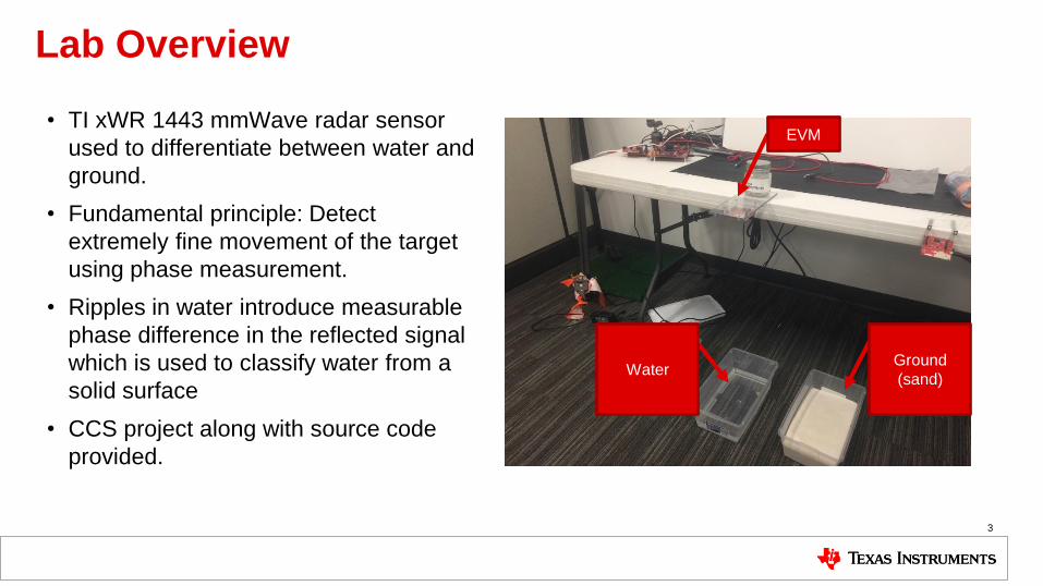
Lab Overview
• TI xWR 1443 mmWave radar sensor
used to differentiate between water and
ground.
• Fundamental principle: Detect
extremely fine movement of the target
using phase measurement.
• Ripples in water introduce measurable
phase difference in the reflected signal
which is used to classify water from a
solid surface
• CCS project along with source code
provided.
3
EVM
Water Ground
(sand)

Hardware Setup
4

1. Requirements
• Software
– Pre-requisites
• Latest TI mmWave SDK and all related dependencies
installed as mentioned in the mmWave SDK release
notes.
– Water vs Ground Lab CCS Project
• Download from TI Resource Explorer
– UniFlash
• For flashing firmware images onto
• Download from TI.com/tool/uniflash
– XDS110 Drivers
• For EVM XDS device support
• Included with CCS Installation, or standalone through
TI XDS Emulation Software
– MATLAB runtime R2016b (9.1)
• For running the Water vs Ground Lab GUI
• Download from MATLAB website
• Hardware
– xWR1443 EVM
– Micro USB cable (included in the EVM package)
– 5V/5A Power Supply
• Purchase from Digikey
– A small plastic trough, to be filled with Water or
Sand for the classification lab.
5

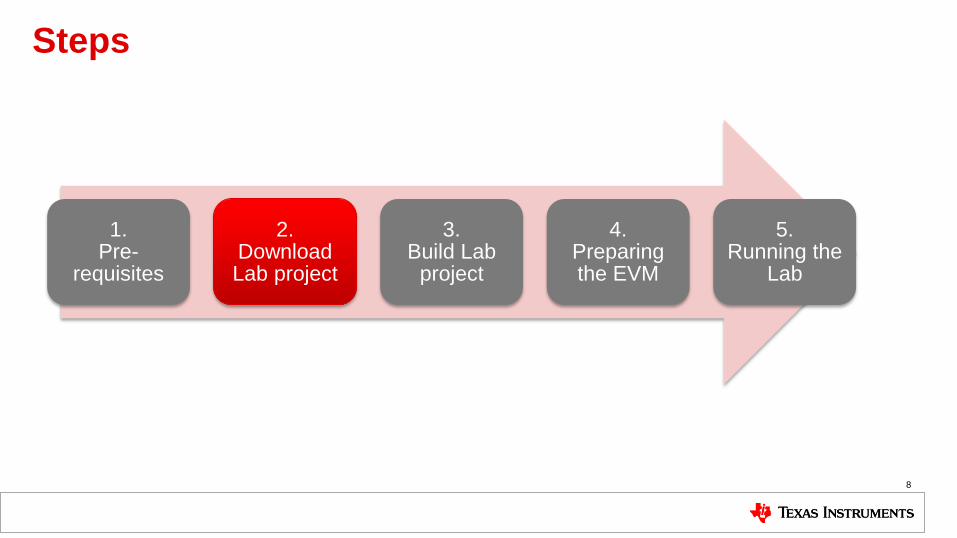
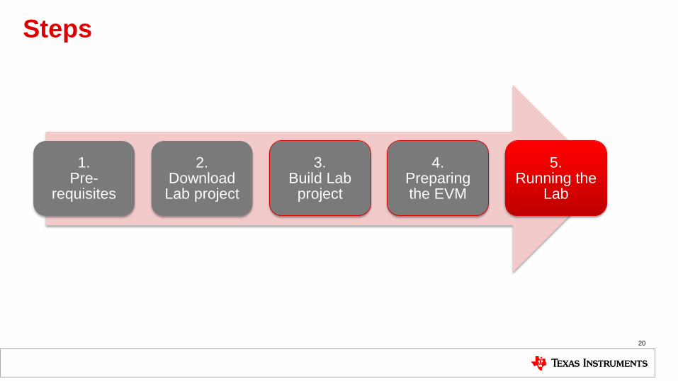
Steps
1. Pre-
requisites
2. Download Lab project
3. Build Lab
project
4. Preparing the EVM
5. Running the
Lab
6

1. Pre-requisites
• It is assumed that you have the latest TI mmWave SDK and all the related tools dependencies installed as mentioned in the mmWave SDK release notes.
– The tools include Code Composer Studio, TI SYS/BIOS, XDC tools, TI ARM compiler, and Perl among other dependencies mentioned in the mmWave SDK release notes.
– The mmWave SDK release notes include the links for downloading the required versions of the above tools.
– Note: For this video, we used mmWave SDK 1.0.0.5 and followed the corresponding release notes. Please follow the release notes for the latest SDK version. The snapshot shown here corresponds to mmWave SDK 1.0.0.5
• Please follow the mmWave SDK release notes to install the latest mmWave SDK and all the required tools if you don’t have these setup already.
• If you have already installed the mmWave SDK and all the required tools, you can move on to the next step i.e. downloading the lab on to your machine.
7
1. Install Pre-requisites 2 3 4 5
Steps
1. Pre-
requisites
2. Download Lab project
3. Build Lab
project
4. Preparing the EVM
5. Running the
Lab
8
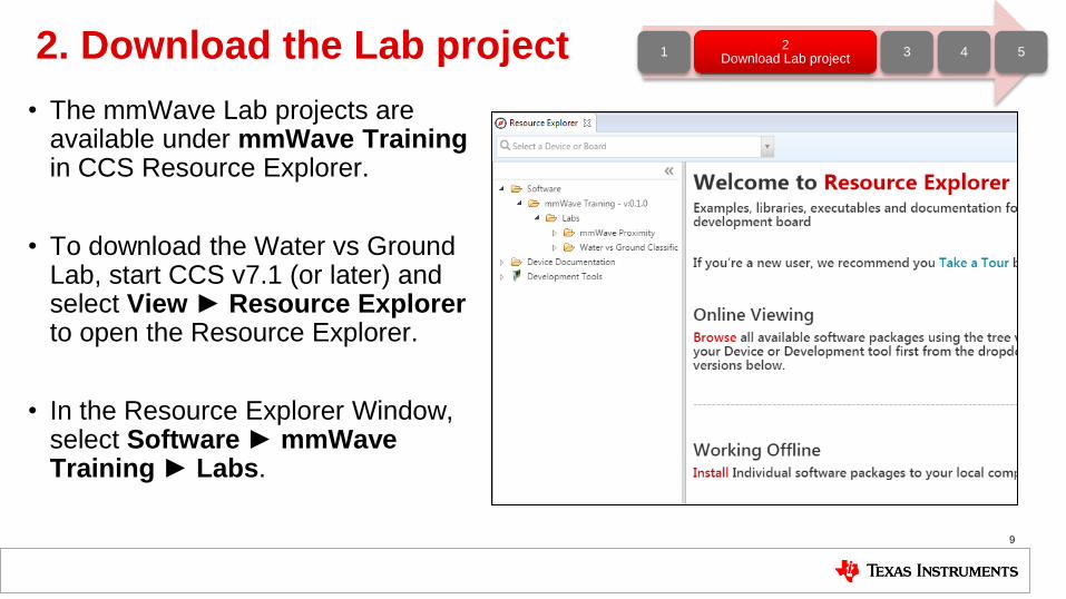
2. Download the Lab project
• The mmWave Lab projects are available under mmWave Training in CCS Resource Explorer.
• To download the Water vs Ground Lab, start CCS v7.1 (or later) and select View ► Resource Explorer to open the Resource Explorer.
• In the Resource Explorer Window, select Software ► mmWave Training ► Labs.
9
1 2
Download Lab project 3 4 5
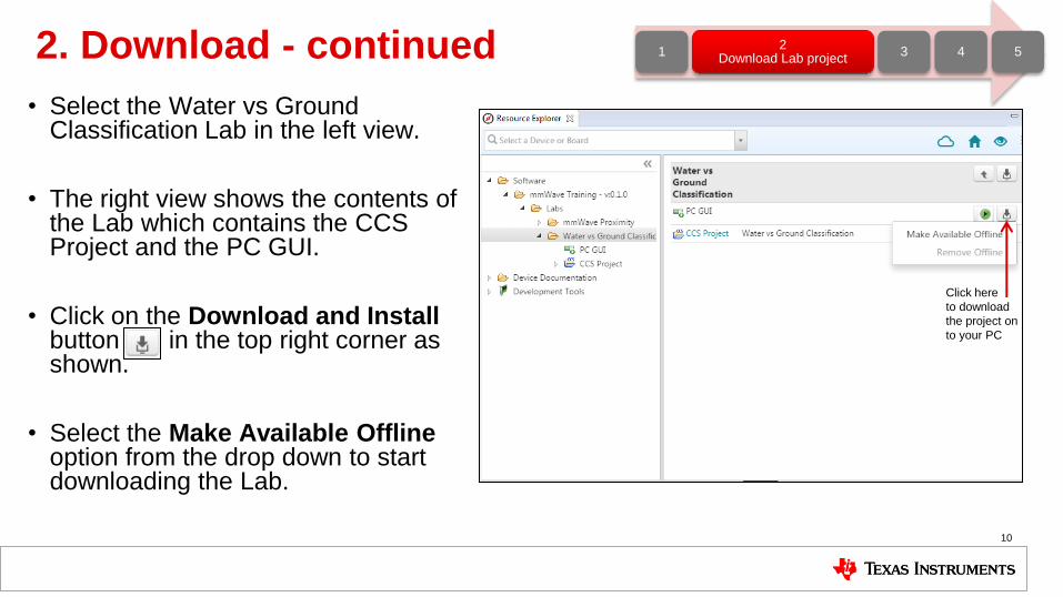
2. Download - continued
• Select the Water vs Ground Classification Lab in the left view.
• The right view shows the contents of the Lab which contains the CCS Project and the PC GUI.
• Click on the Download and Install button in the top right corner as shown.
• Select the Make Available Offline option from the drop down to start downloading the Lab.
10
1 2
Download Lab project 3 4 5
Click here
to download
the project on
to your PC

2. Download - continued
• The project will be downloaded in C:\ti\mmwave_training
• Select the CCS project in the left view as shown.
• Click on the Import to IDE button which should be visible in the right side view after a successful download.
• This copies the project in the user’s workspace and imports it into the CCS project explorer.
– It is important to note that the copy created in the workspace is the one that gets imported in CCS. The original project downloaded in mmwave_training is not touched.
11
1 2
Download Lab project 3 4 5
Click here
to import the
project

2. Download - continued
• After successfully completing the Import to IDE operation, the project should be visible in CCS Project Explorer as shown here.
• At this point, we have successfully downloaded the Water vs Ground Classification Lab and imported it in CCS.
• We are ready to move on to the next step i.e. Building the project.
12
1 2
Download Lab project 3 4 5
Click here
to download
the project on
to your PC
Steps
1. Pre-
requisites
2. Download Lab project
3. Build Lab
project
4. Preparing the EVM
5. Running the
Lab
13

3. Build the Lab
• With the water_ground_lab project selected in Project Explorer, right click on the project and select Rebuild Project.
– Selecting Rebuild instead of Build ensures that the project is always re-compiled. This is especially important in case the previous build failed with errors.
• On successful completion of the build, you should see the output in CCS console as shown here and the following two files should be produced in the project debug directory
– xwr14xx_water_ground_lab_mss.xer4f
– xwr14xx_water_ground_lab_mss.bin
• If the build fails with errors, please ensure that all the pre-requisites are installed as mentioned in the mmWave SDK release notes.
14
1 2 3
Build Lab project 4 5
Steps
1. Pre-
requisites
2. Download Lab project
3. Build Lab
project
4. Preparing the EVM
5. Running the
Lab
15

4.1 Preparing the EVM
• There are two ways to execute the compiled code on the EVM:
– Deployment mode: Flashing the binary (.bin image) on to the EVM serial flash
• In this mode, the EVM boots autonomously from flash and starts running the bin image.
– Debug mode: Downloading and running the executable (.xer4f image) from CCS.
• You will need to flash a small CCS debug firmware on the EVM (one time) to allow connecting with CCS. This debug firmware image is provided with the mmWave SDK.
– As a recap, the build process in Step 3 produces both the .bin and .xer4f images.
• This presentation explains the second method i.e. Debug mode (CCS).
– To prepare the EVM for debug mode, we start with flashing the CCS debug firmware image.
– Please note that the same flashing process can be used to flash the Lab binary to run it in deployment mode.
16
1 2 3 4. Preparing
the EVM 5

4.2 Connecting to the EVM
• Power on the EVM using a 5V/5A power supply.
• Connect the EVM to your PC and check the COM ports in Windows Device Manager
• The EVM exports two virtual COM ports as shown below:
– XDS110 Class Application/User UART (COMUART):
• Used for passing configuration data and firmware to the EVM
– XDS110 Class Auxiliary Data Port (COMAUX)
• Used to send processed radar data output
• Note the COMUART and COMAUX port numbers, as they will be used later for flashing and running the Lab.
17
COMUART: COM38 COMAUX: COM39
• The actual port numbers on your machine
may be different
1 2 3 4. Preparing
the EVM 5
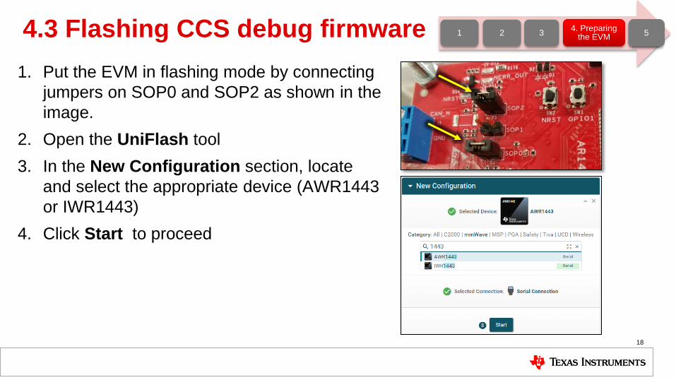
4.3 Flashing CCS debug firmware
18
1. Put the EVM in flashing mode by connecting
jumpers on SOP0 and SOP2 as shown in the
image.
2. Open the UniFlash tool
3. In the New Configuration section, locate
and select the appropriate device (AWR1443
or IWR1443)
4. Click Start to proceed
1 2 3 4. Preparing
the EVM 5
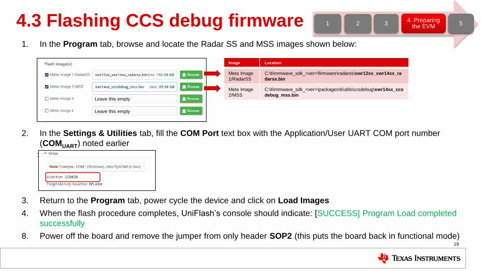
4.3 Flashing CCS debug firmware 1. In the Program tab, browse and locate the Radar SS and MSS images shown below:
2. In the Settings & Utilities tab, fill the COM Port text box with the Application/User UART COM port number
(COMUART) noted earlier
1.
3. Return to the Program tab, power cycle the device and click on Load Images
4. When the flash procedure completes, UniFlash’s console should indicate: [SUCCESS] Program Load completed
successfully
8. Power off the board and remove the jumper from only header SOP2 (this puts the board back in functional mode)
19
Image Location
Meta Image
1/RadarSS
C:\ti\mmwave_sdk_<ver>\firmware\radarss\xwr12xx_xwr14xx_ra
darss.bin
Meta Image
2/MSS
C:\ti\mmwave_sdk_<ver>\packages\ti\utils\ccsdebug\xwr14xx_ccs
debug_mss.bin
1 2 3 4. Preparing
the EVM 5
Leave this empty
Leave this empty
Steps
1. Pre-
requisites
2. Download Lab project
3. Build Lab
project
4. Preparing the EVM
5. Running the
Lab
20
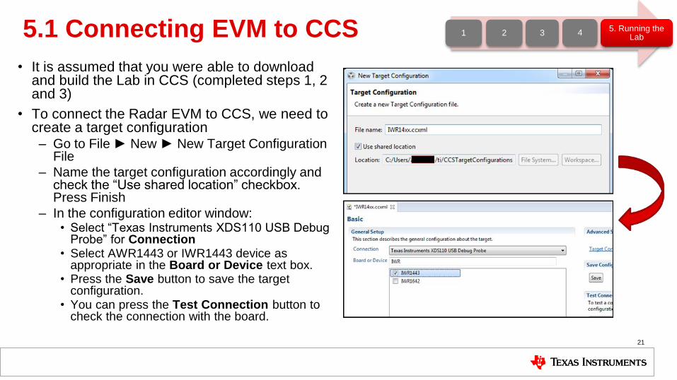
5.1 Connecting EVM to CCS
• It is assumed that you were able to download and build the Lab in CCS (completed steps 1, 2 and 3)
• To connect the Radar EVM to CCS, we need to create a target configuration – Go to File ► New ► New Target Configuration
File
– Name the target configuration accordingly and check the “Use shared location” checkbox. Press Finish
– In the configuration editor window: • Select “Texas Instruments XDS110 USB Debug
Probe” for Connection • Select AWR1443 or IWR1443 device as
appropriate in the Board or Device text box. • Press the Save button to save the target
configuration. • You can press the Test Connection button to
check the connection with the board.
21
1 2 3 4 5. Running the
Lab
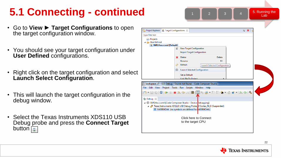
5.1 Connecting - continued
• Go to View ► Target Configurations to open the target configuration window.
• You should see your target configuration under User Defined configurations.
• Right click on the target configuration and select Launch Select Configuration.
• This will launch the target configuration in the debug window.
• Select the Texas Instruments XDS110 USB Debug probe and press the Connect Target button
22
1 2 3 4 5. Running the
Lab
Click here to Connect
to the target CPU
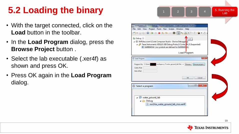
5.2 Loading the binary
• With the target connected, click on the
Load button in the toolbar.
• In the Load Program dialog, press the
Browse Project button .
• Select the lab executable (.xer4f) as
shown and press OK.
• Press OK again in the Load Program
dialog.
23
1 2 3 4 5. Running the
Lab

5.3 Running the binary
• With the executable loaded, press the Run/Resume button
• The program should start executing and generate console output as shown.
• If everything goes fine, you should see the “CLI is operational” message which indicates that the program is ready and waiting for the sensor configuration.
• The sensor configuration is sent using the Lab GUI which is based on Matlab. – Note: Please ensure that MATLAB runtime
R2016b (9.1) is installed as mentioned in the pre-requisites section.
24
1 2 3 4 5. Running the
Lab
Run Program
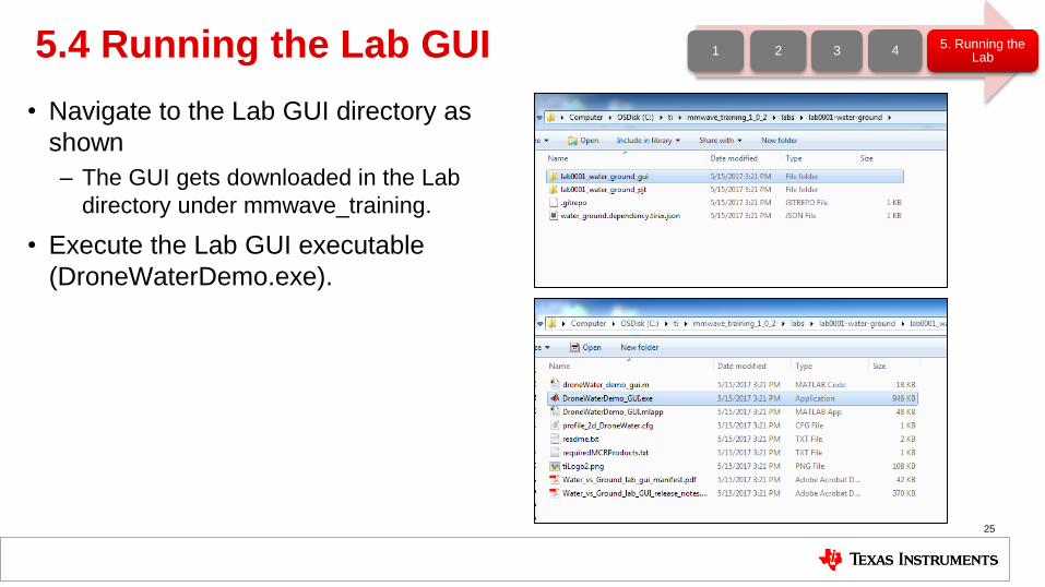
5.4 Running the Lab GUI
• Navigate to the Lab GUI directory as
shown
– The GUI gets downloaded in the Lab
directory under mmwave_training.
• Execute the Lab GUI executable
(DroneWaterDemo.exe).
25
1 2 3 4 5. Running the
Lab
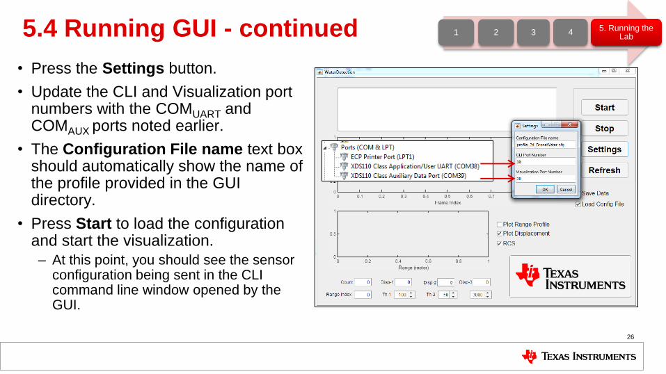
5.4 Running GUI - continued
• Press the Settings button.
• Update the CLI and Visualization port numbers with the COMUART and COMAUX ports noted earlier.
• The Configuration File name text box should automatically show the name of the profile provided in the GUI directory.
• Press Start to load the configuration and start the visualization.
– At this point, you should see the sensor configuration being sent in the CLI command line window opened by the GUI.
26
1 2 3 4 5. Running the
Lab
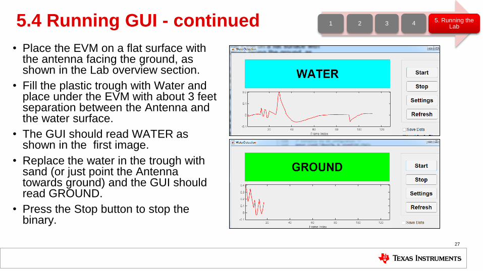
5.4 Running GUI - continued
• Place the EVM on a flat surface with the antenna facing the ground, as shown in the Lab overview section.
• Fill the plastic trough with Water and place under the EVM with about 3 feet separation between the Antenna and the water surface.
• The GUI should read WATER as shown in the first image.
• Replace the water in the trough with sand (or just point the Antenna towards ground) and the GUI should read GROUND.
• Press the Stop button to stop the binary.
27
1 2 3 4 5. Running the
Lab
Learn more about TI mmWave Sensors
• Learn more about xWR1x devices, please visit the product pages
– IWR1443: http://www.ti.com/product/IWR1443
– IWR1642: http://www.ti.com/product/IWR1642
– AWR1443: http://www.ti.com/product/AWR1443
– AWR1642: http://www.ti.com/product/AWR1642
• Get started evaluating the platform with xWR1x EVMs, purchase EVM at
– IWR1443 EVM: http://www.ti.com/tool/IWR1443BOOST
– IWR1642 EVM: http://www.ti.com/tool/IWR1642BOOST
– AWR1443 EVM: http://www.ti.com/tool/AWR1443BOOST
– AWR1642 EVM: http://www.ti.com/tool/AWR1642BOOST
• Download mmWave SDK @ http://www.ti.com/tool/MMWAVE-SDK
• Ask question on TI’s E2E forum @ http://e2e.ti.com
28

29