three dimensional cellular structures enhanced … seedling sma...three dimensional cellular...
TRANSCRIPT

1
Three Dimensional Cellular Structures Enhanced By Shape Memory Alloys
Principal Investigator: Michael V. Nathal, GRC/Advanced Metallics Branch
David Krause, Nathan Wilmoth, Eric Baker and Brett Bednarcyk, GRC/Mechanics and Life
Prediction Branch; Santo Padula, GRC/Advanced Metallics Branch
Summary
This proposal seeks to explore and develop lightweight structural concepts married with
advanced “smart” materials to achieve a wide variety of benefits in airframe and engine components.
In this first year effort, we developed and assembled the methods to address the key aspects of these
structures, including structural testing and modeling. The test results demonstrated good structural
performance, validated the deformation models, and demonstrated shape memory behavior in the cast
lattices.
Introduction
The technical literature abounds with lightweight structural
concepts using periodic cellular structures such as honeycombs
and lattice block materials. Honeycombs have been primarily
used in lightweight sandwich structures and are some of the most
efficient (strength/density) structures in many important loading
situations such as bending. Lattice block, consisting of truss
architectures at a micro-or meso-scale, are preferred over
honeycombs when the loading situations are more three
dimensional, or when honeycomb fabrication is not compatible
with the desired material selection. In the past 5 years, an exciting
outgrowth of these concepts is the development of “auxetic”
structures, which are characterized by negative Poisson’s ratios
(indicating that a material/structure gets thicker when it is stretched,
the opposite of normal behavior). The combination of strength and
flexibility of these structures enable many innovative lightweight
structural concepts such as morphing wings and fan blades, and
auxetics are also projected to have improved impact resistance and
therefore have relevance to fan containment systems. Constructing
the cellular structures from shape memory alloys (SMAs) provides
even greater potential. SMAs can be used in two ways, depending
on alloy selection and temperature. First, SMAs can be designed to
take advantage of the shape memory effect. Here, the structure can
change shape as a response to heating and cooling cycles to achieve
morphing behavior, or alternately a self-healing concept where
damage from an impact event can be recovered via a thermal treatment. Secondly, SMAs can be
designed to be superelastic, where extremely high deformations and loads can be achieved while still
behaving in a reversible manner similar to an elastic response (and thereby allowing long lives and
durability in fatigue, gust and impact loading situations).
The number of materials that can
actually be made into these cellular structures
has been limited to some plastics and a few
relatively soft metallic alloys. Thus, most of
these morphing concepts remain as computer
models or as simple benchtop models. We
Auxetic morphing airfoil from
Spadoni et al. 2005
Lattice Block
Traditional
honeycomb
Auxetic
honeycomb

2
have attempted to improve the aerospace relevance of these structures by active engagement with
outside companies to develop manufacturing methods via SBIR awards. Our collaboration with T45
Inc., through a Phase II SBIR effort (initiated in July 2011 and still continuing), has demonstrated the
initial manufacturing feasibility of SMA lattice blocks, titanium auxetics and SMA auxetics.
Application of these SMA-based structural concepts and exploiting their unique properties will
require detailed understanding of mechanical properties and deformation behavior under cycling
conditions, which are beyond the scope of the SBIR contract with T45, and is the focus of the ARMD
Seedling Fund effort. Our concept is to apply SMAs to lattice and auxetic structures that will expand
capabilities into three dimensional actuation, new lightweight and flexible flap and winglet designs,
variable geometry inlets and nozzles, as well as highly-impact resistant structures. Although our
primary goal is to demonstrate performance of SMA-based lattice block and auxetic structures, we
included Ti-6-4 to serve as a baseline for comparison to the SMAs, and as a lower risk material to
demonstrate the lattice technologies. In addition, Ti-6-4 auxetics offer substantial benefits by
themselves.
Potential impact on NASA and national aeronautics challenges
NASA subsonic and supersonic programs have N+2 and N+3 goals for fuel efficiency and noise
that can be met be utilizing innovative lightweight structural concepts such as morphing wings, inlets,
nozzles and fan blades. The current SFW and SUP projects are funding improved SMA alloy
development and simple one-dimensional SMA actuation concepts, such as wires pulling on a lever,
or a tube rotating a flap. These SMA-based concepts provide substantial weight savings over state-of-
the-art actuation systems, and are frequently enabling. Even greater benefits can be achieved, and
even more components can be available for morphing designs via integrating these three dimensional
structures. The benefits of auxetic structures, as well as any superelastic structure, are too new to
have been fully explored. Improved morphing capacity, improved structural optimization, improved
gust load alleviation, and improved impact resistance are all envisioned.
It is expected that successful demonstration of properties and conceptual design will lead to
further development in the SFW and/or SUP projects [Note: currently all SUP work on SMAs is
being transferred to the new Aero Sciences project]. Lattice structure optimization will be the initial
focus of the FAP task, along with incorporation of NASA-developed SMA’s with higher temperature
or higher actuation performance as well. This will be followed by component demonstrations. The
potential for a separate entry into a fan containment project is also possible, with either the Ti alloy or
an SMA. Successful demonstration of the technology at TRL= 3 can also result in transition of the
technology to ERA – Phase III.
PHASE I PROGRESS REPORT
The objectives of Phase I were to demonstrate shape memory behavior in both lattice and
auxetic structures and compare the results with a more conventional aerospace Ti alloy as a baseline.
This demonstration was to be supported by testing and modeling tasks to provide the understanding
required for future design and optimization efforts.
1. Material Processing
The number of lattice castings supplied by T45 was less than originally planned for two
reasons. First, there was a considerable delay in the SBIR Phase II program, which delayed all Phase
II contracts by roughly 5 months. Second, there were technical issues related to a higher incidence of
casting defects. This resulted in T45 delaying delivery of the original planned castings until it could
deliver higher quality castings. Most of the SMA castings as well as all of the auxetic castings we
were expecting in March, 2012 have yet to be delivered. The SMA castings that we did receive have
a higher population of casting defects than T45 would normally deliver, but we elected to receive
these in order to get at least a preliminary indication of SMA lattice behavior. Cracks were the most

3
significant defect, and occurred particularly at lattice nodes. The particular composition for this
work, Ni-50at% Ti, was chosen because of its very high shape memory actuation capacity. However,
this alloy is not optimally processed by casting, and substantial amounts of the deleterious Ti2Ni
phase were found during microscopic characterization of the castings. Attempts to minimize this
embrittling phase by modifying the casting parameters are in progress. If these trials are
unsuccessful, a new Ni-rich alloy (Ni-49.8at % Ti) may be the best choice for future castings.
Defects were present in the Ti-6-4 castings also, but at a much lower frequency than the SMA
castings. Ongoing discussions with T45 indicate that substantial progress in process development has
been made, and delivery of the remaining castings in late summer is anticipated. A status update
briefing is scheduled after the latest round of casting trials is completed in mid June. Despite the
defective castings, the lattice structure was sufficiently robust such that good structural performance
was measured and model validation was accomplished.
2. Ligament Testing
Both 90o and 45
o ligaments were machined from
the Ti-6-4 and SMA lattice blocks in preparation for testing
(Fig 2). Note that these test samples include lattice nodes, a
likely site for casting defects. These unconventional
geometries required a new gripping system to be designed
in order to test in tension and compression. After several
iterations, a clamping grip was devised and down-selected.
Duplicate tension and compression tests of Ti-6-4
ligaments at 23, 165 and 200oC were completed, and
representative stress-strain curves are shown in Figure 3a. In general, the measured strengths were
only slightly lower than published data for conventionally processed materials, indicating that the
casting process was producing acceptable microstructures. Some ligaments exhibited early failure,
which is most likely due to casting defects. Obtaining crack-free tensile specimens from the SMA
lattices has proven to be more difficult, so the only successful tests have been in compression, and
compressive strains up to 15% were obtained without failure.
Ligament testing results were used as calibration data for the finite element modeling
described below. In addition, the SMA specimen compressed at room temperature was subsequently
heated to examine shape memory behavior. Approximately 3% strain was recovered upon heating,
which is consistent with the expected behavior of the alloy. These tests successfully demonstrated
shape memory behavior of the ligaments.
Fig. 3 Ligament test results along with material calibration curve fits to existing Abaqus constitutive
models. (a) Ti-6-4 in tension and compression. (b) SMA in compression.
0
200
400
600
800
1000
1200
1400
1600
0.00 0.05 0.10 0.15 0.20 0.25
Stre
ss (M
Pa)
Strain
Cast Iron Plasticity Model - Compression
Experiment - Compression
Cast Iron Plasticity Model - Tension
Experiment - Tension
0
20,000
40,000
60,000
80,000
100,000
120,000
140,000
160,000
180,000
200,000
0.00 0.05 0.10 0.15 0.20
Str
ess
(Psi
)
Strain
SMA Compressive Ligament Test
Plasticity Model
Fig. 2 Ligament specimens
4
23. Model development
The purpose of the modeling is to ensure a proper understanding of the physics of lattice
deformation has been achieved, such that future extrapolations to new structures as well as
optimization of the lattice structure can be performed with confidence. This will allow rapid, low
cost evaluation of multiple structural concepts before investing in experimental demonstration efforts.
A Python script has been written to automatically generate Abaqus finite element models of
the arbitrary lattice geometries. The script is parametric, so it is quick and easy to generate models
for different configurations, run the finite element model, and post-process the results. The ligaments
are treated as beams with arbitrary nonlinear material behavior that may also experience nonlinear
geometric effects. Example lattice geometries generated using the Python script are shown in Fig. 4.
Fig. 4. Actual lattice casting and sample geometries generated with the Python Script.
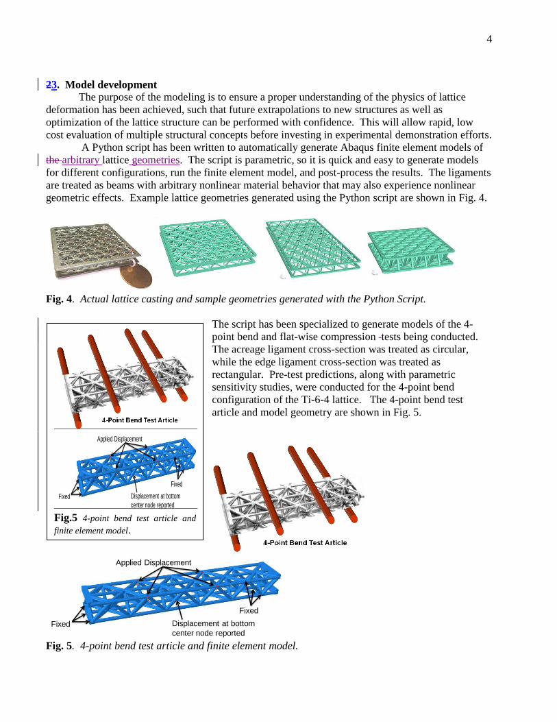
The script has been specialized to generate models of the 4-
point bend and flat-wise compression tests being conducted.
The acreage ligament cross-section was treated as circular,
while the edge ligament cross-section was treated as
rectangular. Pre-test predictions, along with parametric
sensitivity studies, were conducted for the 4-point bend
configuration of the Ti-6-4 lattice. The 4-point bend test
article and model geometry are shown in Fig. 5.
Fig. 5. 4-point bend test article and finite element model.
Fixed
Applied Displacement
Fixed
Displacement at bottom
center node reported
Fig.5 4-point bend test article and
finite element model.
Fixed
Applied Displacement
Fixed
Displacement at bottom
center node reported

5
After performing a mesh senstivity study to arrive at a globally converged mesh, a parametric
sensitivity study was performed by varying the material representation, the height of the panel, and
the ligament diameter. At the time of the pre-test predictions, only tensile ligament test results were
available, and they showed some variability. The nonlinear material response was modeled using
von Mises plasticity, and to capture the variability in the tensile test results, two sets of material data
were used in the sensitivity studies, as shown in Fig. 6.
Variation of the panel height was intended to examine the effect of the fact that the ligament
nodes in the as-built lattice are not centered at the center of the face ligements. This is shown in Fig.
7. To assess the impact of this offset, panel heights (distance between face ligament centroids) of 18
and 21.5 mm were examined.
Finally, ligament diameters of 3.25, 3.5, and 3.75 mm were examine to assess the impact of
cross-sectional area variability, which has been observed in the lattice ligaments. The predicted
applied load vs. bottom center point deflection is plotted in Fig. 8, along with deformation contours at
various points. These two curves represented what what believed to be the best pre-test predictions,
while still factoring in the variable Ti-6-4 material response as shown in Fig. 6. The predicted
response involves a peak, followed by softening as the significant buckling of the top face struts is
predicted. The model was loaded in diplacement control (on top face points, see Fig. 5) to a
maximum of 4 mm, then unloaded. A significant amount of permanent set, due to plasticity, was
predicted.
The full set of results from the parametric study, in which the panel height, Ti-6-4 material
representation, and the ligament diameter were varied, are shown in Fig. 9. These results indicated
that panel height and strut diameter have a significant effect on the lattice 4-point bend response
(changes on the order of 35%), while the Ti-6-4 material variation examined is minor (changes on the
order of 5%).

6
Fig. 6. Abaqus plasticity model fit to room-temperature Ti-6-4 ligament test data that was used to
capture the variability of the material response.
Fig. 7. Offset between face ligament centroids and actual node location.
0
100
200
300
400
500
600
700
800
900
1,000
0.00 0.01 0.02 0.03 0.04 0.05 0.06 0.07
Stre
ss (
MP
a)
Strain (in/in)
Test: TL_RT_3T
Test: TL_RT_4B
Test: TL_RT_15B
Abaqus Plasticity Model - High
Abaqus Plasticity Model - Low

7
Fig. 8. Pre-test prediction of Ti-6-4 lattice block 4-point bend response.
Fig. 9. Full set of parametric simulations on the 4-point bend response of the Ti-6-4 Lattice.
0
5,000
10,000
15,000
20,000
25,000
0 1 2 3 4 5 6
Tota
l Ap
plie
d F
orc
e (
N)
Center Point Displacement (mm)
D = 3.5, M = Hi, H = 18 (BL) D = 3.5, M = Hi, H = 21.5 D = 3.25, M = Hi, H = 18
D = 3.75, M = Hi, H = 18 D = 3.5, M = Lo, H = 18 D = 3.25, M = Hi, H = 21.5
D = 3.75, M = Hi, H = 21.5 D = 3.25, M = Lo, H = 21.5 D = 3.5, M = Lo, H = 21.5
D = 3.75, M = Lo, H = 21.5 D = 3.25, M = Lo, H = 18 D = 3.75, M = Lo, H = 18
MeshDiv = 10

8
4. Structural Benchmark Testing
The Phase I structural benchmark testing effort included mechanical tests of complete lattice
structure test articles. By evaluating the mechanical response to prototypical structural loadings, this
work provided physical evidence of advantages in the lattice structure configuration, highlighting
light weight, efficiency, and redundancy in the cellular structure. In addition, the testing
demonstrated shape memory response in a lattice structure, as opposed to the simple geometry of a
material test coupon. As described in the next section, the tests also provided data for verification of
the soundness of the model development effort.
The structural benchmark test plan for Phase I included a variety of mechanical tests on similarly
configured lattice structure test articles fabricated both from a cast lightweight aerospace titanium
alloy (Ti-6-4) and from a cast SMA (NiTi). The planned testing provided for structural response
evaluation at room temperature and at elevated temperature (165 °C) for “long-beam” bend tests with
four-point loading, and for through-thickness flat-wise compression load tests. Due to the previously
described delays in receiving acceptable test articles, benchmark testing was restricted to 1)
demonstrate preparation for and validity of the two test methodologies; and, 2) provide initial test
results for three test articles in two configurations fabricated from the two cast alloys.
Lattice structures cast in Ti-6-4 were received in two configurations: 100 x 100 x 25 mm panels,
and a 50 x 200 x 25 mm panel. The former were retained for future flat-wise compression testing,
while the latter was cut into three long-beam bending test articles. Lattice structures cast in the SMA
NiTi were also received, in the 100 x 100 x 25 mm panel configuration, suitable for flat-wise
compression tests. All castings exhibited visible defects, including porosity and cracks at nodes and
struts.
Structural Benchmark Testing Accomplishments
The structural benchmark testing accomplishments include contributions to Phase I Products by
providing mechanical test properties and shape memory test data for lattice block structures made
from SMA and Ti-6-4, and by providing structural response data that was used for validation of the
finite element-based deformation model. These contributions are further described in the following
paragraphs. Note that castings in the auxetic structure configuration were not available in this time
period for reasons previously described.
The Phase I Task 1 objective to prepare for testing was met by acquiring test fixtures,
instrumentation, and furnace/heating hardware, and by preparing the mechanical test rigs and data
acquisition systems to perform structural benchmark testing. Task 2 was not applicable to structural
benchmark testing. The Task 3 objective to perform isothermal testing was accomplished for test
articles fabricated from conventional lattice castings of both Ti-6-4 and SMA (note again that the
auxetic structure configuration was not available in this time period). The Task 4 objective to
demonstrate strain recovery through thermal treatment was accomplished by loading two SMA lattice
structures to significant strain levels in flat-wise compression; in the first case, the structure fractured
in the process due to pre-existing casting defects, so strain recovery was not consequential and
therefore not attempted. In the second case, the SMA test article was loaded to result in 2%
permanent structural strain, 60% of which was recovered following heat treatment. Further
description of the testing is included in the following paragraphs. The Task 5 objective to prepare a
final report is satisfied by completion of this manuscript.
Structural Benchmark Testing Description and Results

9
Three series of structural benchmark tests
were completed: 1) long-beam bend (four-point
load) testing of a cast Ti-6-4 lattice structure; 2)
flat-wise compression strength testing of a cast SMA NiTi lattice structure; and, 3) flat-wise
compression yield of a cast SMA NiTi lattice structure testing with thermal recovery. All test series
were conducted isothermally at room temperature
(22 °C).
The first test series was performed on Ti-6-4
Test Article S/N 22C; it had overall dimensions of
200 x 50 x 25 mm and was 12 by 3 unit cells,
composing three longitudinal “trusses.” The
average strut diameter was 3.505 mm. The long-
beam bend test configuration (Fig. 10) of the 50 kN
MTS load frame was symmetrical, with lower
reaction supports at two-node locations spaced 180
mm apart, and upper load rollers also at two-node
locations spaced 72 mm apart. Four-point loading
placed the entire middle span between load rollers
under the same maximum nominal moment value.
In bending, the test article’s structural limits were
explored through a series of increasing load ramp
cycles (Fig. 11). Elastic loadings to 2.224 kN,
4.448 kN, and 13.34 kN total load were completed with almost no measurable nonlinearity or
hysteresis upon return to zero load. The elastic series was followed by loading to first observed strut
failure at 20.01 kN; the response remained quite linear until approximately 18 kN. Specimen
inspection using optical microscopy could not locate the suspected fracture. Additional residual
strength testing was continued under test machine stroke control, when 18.49 kN strength was
measured at second strut failure. Residual strength of 12 kN was observed until the machine stroke
limit of 5.5 mm specimen deflection was reached (Fig. 12). Post-test visual inspection revealed two
fractures, one at a node and one through a strut.
Figure 11. Bend test load ramps. A series of bend test
load ramps were applied to the lattice structure beam.
-25
-20
-15
-10
-5
0-25
-20
-15
-10
-5
0
0 20 40 60 80 100 120
Mid
-Sp
an
De
fle
ctio
n, m
m
To
tal L
oa
d,
kN
Test Time, min
Ti 6-4 Specimen 22-C, 4-Point Bend Test
Load Plots(solid lines)
Deflection Plots(light dash lines)
Figure 12. Failure and residual strength tests. After
first failure, most lattice structure strength remained.
-25
-20
-15
-10
-5
0
-6-5-4-3-2-10
To
tal L
oa
d,
kN
Mid-Span Deflection, mm
Ti 6-4 Specimen 22-C, 4-Point Bend Test
Loading5 - 0.22 mm/minLoading6 - 0.45 mm/minLoading7 - 0.34 mm/min
Figure 10.
Long-beam bend test set-up. Lattice structure test
article is shown mounted in hinged four-point load
fixtures.

10
The second test series was performed on SMA NiTi Test
Article Heat 1131 S/N 2-1; it had overall dimensions of 98 x
99 x 26 mm and was five unit cells square. The average strut
diameter was 3.858 mm. The flat-wise compression strength
test was performed first on the 50 kN MTS load frame and included a spherical joint fixture and rigid
platens to assure uniform loading of all 18 upper and 18 lower “face sheet” nodes (Fig. 13). In
compression, the test frame’s load limit was approached prior to significant deformation or failure of
the test article; a peak loading of 41.9 kN was recorded at 0.41 mm panel deflection. To further
explore the load-carrying ability of the SMA test article, a 450 kN-capacity Instron load frame was
reconfigured with the spherical joint and platen fixtures. Upon loading, first failure was identified at
155 kN total panel load; in situ inspection revealed a crack in the specimen’s integrally cast lower
perimeter tension frame, probably at a pre-existing flaw. Continued higher loading under stroke
control demonstrated load redistribution capability within the lattice structure, providing additional
strength to achieve the peak load of 170 kN at 1.6 mm deflection, approximately 6% structural
through-thickness deformation (Fig. 14). Post-test visual inspection revealed additional cracks in the
upper and lower perimeter tension frames. This altered the structure’s stress distribution, placing
struts in bending and progressively failing most nodes and cracking many struts at mid-length
locations. Because of the extensive non-reversible damage, post-test thermal treatment for strain
recovery (self-healing) was not warranted.
Figure 13. Flat-wise compression test.
Lattice structure test article is shown
mounted between platens, with spherical
joint fixture beneath specimen.
Figure 14. Compression strength test. Additional strength and
deformation were available after the initial break of the first SMA test
article at 155 kN.
-180
-160
-140
-120
-100
-80
-60
-40
-20
0
-3.5-3.0-2.5-2.0-1.5-1.0-0.50.0
Pa
ne
l L
oa
d,
kN
Total Panel Deflection, mm
NiTi Specimen 1131 S/N 2-1 Compr. Test
Test1 LoadTest2 Load

11
The third test series was performed on SMA
NiTi Test Article Heat 1131 S/N 6-2; it had the
same overall dimensions and geometry as Test
Article S/N 2-1. The flat-wise compression yield
test with strain recovery was performed on the 450
kN-capacity Instron load frame configured with the
spherical joint and platen fixtures (similar to Fig.
13). In compression at a rate of 0.305 mm per
minute, a peak load of 101 kN was attained at a
deflection of 0.65 mm, equivalent to 3.1%
compressive structural strain (Fig. 15). No
evidence of cracking or failure of the structure was
observed. Following release of the load, the
residual compressive through-thickness strain was
1.95%; this value relaxed to 1.58% after a period of
15 minutes at room temperature. Post-test heat treatment at 95 °C resulted in strain recovery to
1.33%, while an additional heat treatment at 200 °C for 120 minutes produced strain recovery to
0.79% -- 60% of the initial inelastic deformation after release of the load (Fig. 16).
Structural Benchmark Testing Conclusions
In general, familiarity with the lattice structure test articles revealed that the large surface area
and configuration of the cellular casting make difficult non-destructive inspection for determining the
presence of all cracks and defects.
The long-beam bend testing of a Ti-6-4 lattice structure exhibited almost no inelastic behavior for
loadings to 13.34 kN, indicating that yield at local stress risers if it existed did not affect the overall
structural response. After the first and second tensile failures of a strut (or node), much strength and
deformation capability existed, demonstrating the advantages of the highly redundant lattice
structure, with resilience and availability of alternative
load paths. In bending, the top compression struts
plastically deformed before the first bottom strut
tensile rupture was discovered. For aerospace service,
this is a valuable benefit, because it provides an
observable sign of distress before structural failure.
Necking deformation at strut tensile breaks indicates
fully developed plasticity above the Ti-6-4 material’s
yield point. As a testing consideration, large specimen
deformations observed require careful selection of the
appropriate load and support fixtures to permit free
rotations and lateral movements.
Flat-wise compression testing of SMA NiTi lattice
structures indicated insensitivity to defects for this
load case; the test articles had several known casting
defects present, but until failure of the integral tensile
frame in one case, the defects did not affect test results
to a measurable degree. The initial 0.2 mm
Figure 15. Compression yield test. The second SMA
lattice structure test article was loaded in compression to
produce approximately 2% residual deformation.
Figure 16. Recovery of compressive strain. Thermal
treatment restored 60% of the initial inelastic strain
resulting from extreme compression of the test article.
0%
10%
20%
30%
40%
50%
60%
70%-3.5%
-3.0%
-2.5%
-2.0%
-1.5%
-1.0%
-0.5%
0.0%
% S
tra
in R
ec
ove
ry
Th
rou
gh
-Th
ick
ne
ss
Str
ain
, %
NiTi LBS Heat 1131, S/N 6-2
through-thickness strain
inelastic strain recovery
Figure 15. Compression yield test. The second SMA
lattice structure test article was loaded in compression to
produce approximately 2% residual deformation.
-120
-100
-80
-60
-40
-20
0
-0.7-0.6-0.5-0.4-0.3-0.2-0.10.0
Pa
ne
l L
oa
d,
kN
Total Panel Deflection, mm
NiTi LBS Heat 1131, S/N 6-2 Compr. Test

12
unrecovered deformation of the first compression test article upon unloading from the first cycle to
41.9 kN total load may have resulted from local yielding, as the node outer contact surfaces on the as-
received casting were not milled to provide a planar surface, or from general inelastic behavior. In
the former case, non-uniform loading would develop at the nodes when first contacting the rigid
platens’ flat surfaces. Similarly, this may be responsible for the condition of initial increasing
stiffness with load during the compression tests. For the first compression test article, upon second
loading the compliance to 41.9 kN was greatly different than for the first cycle, a behavior unique and
characteristic of the SMA material. For the second compression test article, the recovery of 60% of
the initial inelastic strain through heat treatment is representative of the shape memory alloy. Further,
upon subsequent repeated load cycling, nearly all inelastic strain is expected to be recoverable
through heat treatment, an advantageous property of the NiTi alloy composition. Finally, the high
value of structural deformation at peak strength load capacity of the SMA test article further indicates
an opportunity for high strain recovery (self-healing) upon thermal treatment.
5. Analytical Verification
The agreement between the most representative pre-test prediction and the bend test
performed on the Ti-6-4 lattice is shown in Fig. 17. As shown, the model predicts the inital slope and
onset of nonlinearity well, but the softening associated with top ligament buckling is absent in the test
data. In the test, failure occurred in one of the two ligaments in the bottom face as shown. Note that
no attempt to model this type of ligament fracture has yet been made. The lack of softening in the
test results indicates that buckling of the top face struts was limited in the test and overpredicted in
the model.
Fig. 17. Correlation between pre-test prediction and Ti-6-4 LBS 4-point bend test data.
0
5,000
10,000
15,000
20,000
25,000
0 1 2 3 4 5 6
Tota
l Ap
pli
ed
Fo
rce
(N
)
Center Point Displacement (mm)
D = 3.5, M = Hi, H = 21.5
D = 3.5, M = Lo, H = 21.5
Test Data
MeshDiv = 10
Tensile Failure in bottom face strut

13
In an attempt to explain the discrepancy, compressive ligament test data, which became
available after the 4-point bend test, was modeled using an existing model in the Abaqus library
(“cast iron plasticity model”), which allows distinct tensile and compressive material plastic
behavior. The fit of the model to experimental room-temperature Ti-6-4 ligament data is shown in
Fig. 3a, where now the compressive response is hardens significantly more than the tensile response.
Switching to this material model decreased but did not eliminate the amount of softening in the
model (see Fig. 18). To further suppress the buckling in the top face ligaments, a non-circular
ligament cross-section was considered in the top face of the lattice only. This simulates the tear-drop
shaped cross-section that has been observed (see Fig. 18) and enables the ligaments to have greater
resistance to out-of-plane bending and thus greater buckling resistance. For simplicity, a rectangular
cross-section was considered as shown in Fig. 18.
Fig. 18. Correlation of model, altered to suppress top face ligament buckling, with experiment for
the Ti-6-4 lattice 4-point bend test.
Fig. 18 compares the altered model with the experimental data. While the rectangular shape of the
top face ligaments is not completely representative, this simulation shows that by suppressing
buckling of the top face ligaments, the test data can be captured. An additional feature that will also
suppress top face ligament buckling is the thicker ligament sections near the nodes, which was not
included in the model geometry. This reduces the free-span of the ligaments, which will reduce their
tendency to buckle. This effect will be examined in the future.
Finally, a pre-test prediction was made for the flat-wise compression behavior of the SMA
lattice. The actual casting and the Abaqus model are shown in Fig. 19. To simulate the flat-wise
compression test, the bottom nodes in the model were fixed and the top nodes were displaced
downward at a constant rate. As a first step, the SMA material was modeled using the Abaqus von
2.8 mm(A increased by 10%)
3.8
mm
Top
Face
Strut X-
Section
tear-drop cross-section

14
Mises plasticity constitutive model. The fit of this model to SMA ligament tensile test data is shown
in Fig. 3b. More realistic SMA constitutive models will be employed in the future. The agreement
between the pre-test flat-wise compression prediction and experiment is shown in Fig. 20. The
model matches the experiment well for the initial slope and onset of nonlinearity. The model is then
slightly more compliant than the test data. The model response begins to stiffen in association with
the SMA material stiffening response shown in Fig. 3b. The model then was not able to converge
due to the extensive buckling of the lattice internal ligaments. Although this cannot necessarily be
considered a predicted failure, it did occur at an applied displacement of 1.18 mm, which corresponds
closely to the applied displacement at first failure in the test (1.16 mm).
Fig. 19. SMA lattice casting and Abaqus finite element model.

15
Fig. 20. Model prediction and experimental results for SMA lattice in compression.
0
20,000
40,000
60,000
80,000
100,000
120,000
140,000
160,000
180,000
0.0 0.2 0.4 0.6 0.8 1.0 1.2 1.4 1.6 1.8
Co
mp
ressi
ve
Re
acti
on
Fo
rce
(N
)
Applied Compressive Displacement (mm)
Test
Pre-Test Prediction Model Did Not Converge
First LigamentFailure
Collapse
2x scale factor