thrall 5-unit articulated well car diy models foot.pdf · thrall 5-unit articulated well car david...
TRANSCRIPT

THRALL 5-UNIT ARTICULATED WELL CAR
D
DIY MODELS44609 W. Canyon Creek Dr. Maricopa, AZ 85139-5019
AVID ALLEN Page 1 04/24/10
DIMENSIONSLength End Units 56’ 2-5/16” Width (Inside Well at Bottom) 8’ - 1 3/4”Length, Inter. Units 50’ 13-3/4” 9’ 2-1/2” Over Top ChordsLength Over Coupler Pulling Faces 268’ 8’ 2-1/2” Between Top ChordsLength Over Strikers 265’ 3-7/8” Length (Inside Well at Bottom) 40’- 2”
WEIGHTLight Weight (Inter. Unit) 31,400 lbs.Capacity Per Unit 126,100 lbs.

2 DIY MODELS
THRALL 5-UNIT ARTICULATED WELL CAR
Trailer-On-Flat-Car (TOFC) and Container-On-Flat-Car (COFC) have become a large business for thetransportation industry. Shipping lines and truckers as well as the railroads have worked to make thisan effective way to handle and transport goods. Containers especially lend themselves to intermodaltransport since they are rectangular, have no wheels or other external components; therefore they canbe stacked in multiple layers aboard ship. Railroads adapted 89-foot flatcars to carry this cargo inlandfrom ports. This is often done with the ”unit train” concept direct from point A to point B with aminimum of yard switching.
In search of greater efficiency, shippers and railroads worked together to find a better method.Southern Pacific designed and American Car and Foundry (ACF) built a group of 5-unit carsarticulated to become one car as the railroads look at it. These cars are capable of carrying 35 or 40-foot containers in a stack of two per unit, hence the trade name “Double Stack”. These cars have anempty weight of about 40,000 lbs. per platform.
Since APL was seeking to maximize the efficiency of container carrying railcars, they pursuedmethods of weight reduction. It was apparent that if they eliminated the bulkheads of the ACF car, asignificant weight reduction would be obtained. The only purpose of the bulkheads on the ACF carswas to keep the upper container on the car. Through the use of a prototype car designed and built bythe Budd Co. (Lo-Pac 2000) to be used as TOFC and COFC both, APL was able to test the practicalityof stacking containers two high by using inter-box connectors which are similar to the ones in use forstacking containers above deck aboard ship. Once this method was determined to be successful, APLin conjunction with Budd and the Thrall Car Co. designed a lightweight well-type railcar, which hasbecome the APL Liner Train of today. The end platforms are capable of carrying two 20 footcontainers in the well with a 40 or 45 foot container on top. The intermediate platforms are built toaccommodate only a 40 foot container in the well with either a 40 or 45 foot container on top. Thesecars have an empty weight of about 31,000 lbs. per platform.
Initially, 3 trains were obtained with 2 of them operating from Los Angeles to Chicago via UP andCNW and the other from Seattle to the East Coast via Conrail east of Chicago. . Other trains have sincebeen obtained and are running from Los Angeles through Houston and New Orleans via SP and on toAtlanta via the Southern Railway. Trailer Train Corporation has recently acquired Thrall units and willrun from the Northwest toward the East.
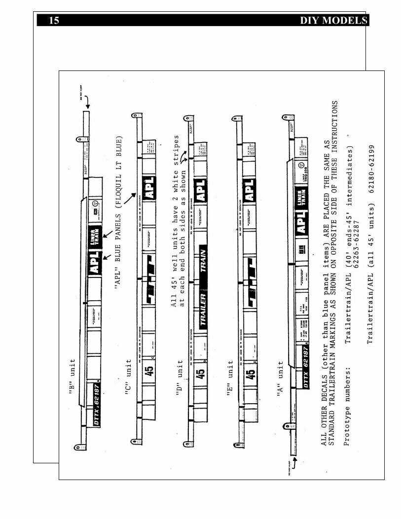
Another modification to the Thrall unit is to add a diesel engine, generator and fuel tank to one of theend units with electrical connections to the other units to provide power for refrigerated containers.These units are painted red as compared to blue for the standard units. All have white lettering.
Each unit of a car carries the same road number with a letter suffix (A through E). The relationship ofthe units is B-C-D-E-A so the railroad practice of an A and B end is maintained. Units A and B haveconventional couplers and units A,B and D have air brake equipment. On the reefer units, the powerequipment is on the A unit.
3 DIY MODELS
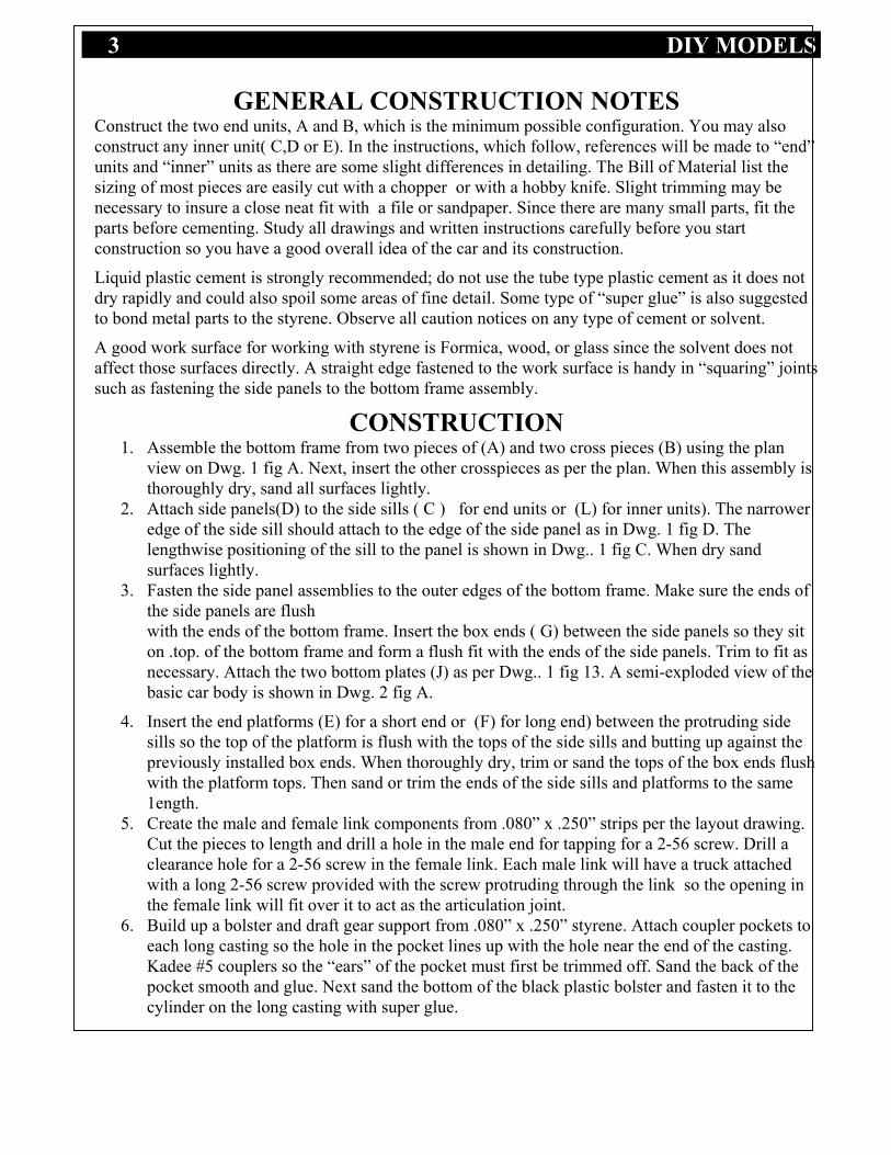
GENERAL CONSTRUCTION NOTESConstruct the two end units, A and B, which is the minimum possible configuration. You may alsoconstruct any inner unit( C,D or E). In the instructions, which follow, references will be made to “end”units and “inner” units as there are some slight differences in detailing. The Bill of Material list thesizing of most pieces are easily cut with a chopper or with a hobby knife. Slight trimming may benecessary to insure a close neat fit with a file or sandpaper. Since there are many small parts, fit theparts before cementing. Study all drawings and written instructions carefully before you startconstruction so you have a good overall idea of the car and its construction.
Liquid plastic cement is strongly recommended; do not use the tube type plastic cement as it does notdry rapidly and could also spoil some areas of fine detail. Some type of “super glue” is also suggestedto bond metal parts to the styrene. Observe all caution notices on any type of cement or solvent.
A good work surface for working with styrene is Formica, wood, or glass since the solvent does notaffect those surfaces directly. A straight edge fastened to the work surface is handy in “squaring” jointssuch as fastening the side panels to the bottom frame assembly.
CONSTRUCTION1. Assemble the bottom frame from two pieces of (A) and two cross pieces (B) using the plan
view on Dwg. 1 fig A. Next, insert the other crosspieces as per the plan. When this assembly isthoroughly dry, sand all surfaces lightly.
2. Attach side panels(D) to the side sills ( C ) for end units or (L) for inner units). The narroweredge of the side sill should attach to the edge of the side panel as in Dwg. 1 fig D. Thelengthwise positioning of the sill to the panel is shown in Dwg.. 1 fig C. When dry sandsurfaces lightly.
3. Fasten the side panel assemblies to the outer edges of the bottom frame. Make sure the ends ofthe side panels are flushwith the ends of the bottom frame. Insert the box ends ( G) between the side panels so they siton .top. of the bottom frame and form a flush fit with the ends of the side panels. Trim to fit asnecessary. Attach the two bottom plates (J) as per Dwg.. 1 fig 13. A semi-exploded view of thebasic car body is shown in Dwg. 2 fig A.
4. Insert the end platforms (E) for a short end or (F) for long end) between the protruding sidesills so the top of the platform is flush with the tops of the side sills and butting up against thepreviously installed box ends. When thoroughly dry, trim or sand the tops of the box ends flushwith the platform tops. Then sand or trim the ends of the side sills and platforms to the same1ength.
5. Create the male and female link components from .080” x .250” strips per the layout drawing.Cut the pieces to length and drill a hole in the male end for tapping for a 2-56 screw. Drill aclearance hole for a 2-56 screw in the female link. Each male link will have a truck attachedwith a long 2-56 screw provided with the screw protruding through the link so the opening inthe female link will fit over it to act as the articulation joint.
6. Build up a bolster and draft gear support from .080” x .250” styrene. Attach coupler pockets toeach long casting so the hole in the pocket lines up with the hole near the end of the casting.Kadee #5 couplers so the “ears” of the pocket must first be trimmed off. Sand the back of thepocket smooth and glue. Next sand the bottom of the black plastic bolster and fasten it to thecylinder on the long casting with super glue.
4 DIY MODELS
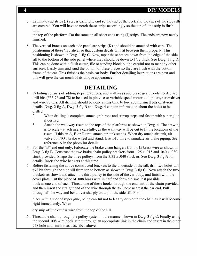
7. Laminate end strips (I) across each long end so the end of the deck and the ends of the side sillsare covered. You will have to notch these strips accordingly so the top of , the strip is flushwiththe top of the platform. Do the same on all short ends using (I) strips. The ends are now neatlyfinished.
8. The vertical braces on each side panel are strips (K) and should be attached with care. Thepositioning of these ‘is critical so that custom decals will fit between them properly. Thispositioning is shown in Dwg. 1 fig C. Now, taper these braces down from the edge of the sidesill to the bottom of the side panel where they should be down to 1/32 thick. See Dwg. 1 fig D.This can be done with a flush cutter, file or sanding block but be careful not to mar any othersurfaces. Lastly trim and sand the bottom of these braces so they are flush with the bottomframe of the car. This finishes the basic car body. Further detailing instructions are next andthis will give the car much of its unique appearance.
DETAILING1. Detailing consists of adding steps, grabirons, and walkways and brake gear. Tools needed are
drill bits (#53,76 and 78) to be used in pin vise or variable speed motor tool, pliers, screwdriverand wire cutters. All drilling should be done at this time before adding small bits of styrenedetails. Dwg. 2 fig A, Dwg. 3 fig B and Dwg. 4 contain information about the holes to bedrilled.2. When drilling is complete, attach grabirons and stirrup steps and fasten with super glue
if desired.3. Attach the walkway risers to the tops of the platforms as shown in Dwg. 4. The drawing
is to scale - attach risers carefully, as the walkway will be cut to fit the locations of therisers. If this an A, B or D unit, attach air tank stands. When dry attach air tank, airvalve but NOT brake wheel and stand. Use .015 wire to simulate air brake piping. Seereference A in the photo for details.
4. For the “B” end unit only: Fabricate the brake chain hangers from .015 brass wire as shown inDwg. 3 fig B. Construct the two brake chain pulley brackets from .125 x .015 and .040 x .030stock provided. Shape the three pulleys from the 3/32 x .040 stock or. See Dwg. 3 fig A fordetails. Insert the wire hangers at this time.
5. Before fastening the above constructed brackets to the underside of the sill, drill two holes with#78 bit through the side sill from top to bottom as shown in Dwg. 3 fig C. Now attach the twobrackets as shown and attach the third pulley to the side of the car body, and finish with thecover plate. Cut the piece of .008 brass wire in half and form the smallest possiblehook in one end of each. Thread one of these hooks through the end link of the chain providedand then insert the straight end of the wire through the #78 hole nearest the car end. Pullthrough all the way and bend over sharply on top of the side sill. Fix in
place with a spot of super glue, being careful not to let any drip onto the chain as it will becomerigid immediately. When
dry snip off the excess wire from the top of the sill.
6. Thread the chain through the pulley system in the manner shown in Dwg. 3 fig C. Finally usingthe second .008 wire hook, run it through an appropriate link in the chain and insert in the other#78 hole and finish it as described above.
5 DIY MODELS
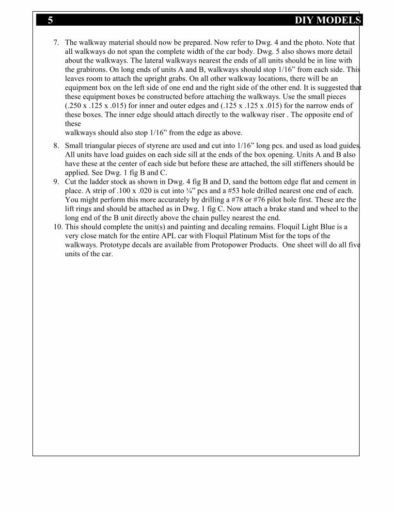
7. The walkway material should now be prepared. Now refer to Dwg. 4 and the photo. Note thatall walkways do not span the complete width of the car body. Dwg. 5 also shows more detailabout the walkways. The lateral walkways nearest the ends of all units should be in line withthe grabirons. On long ends of units A and B, walkways should stop 1/16” from each side. Thisleaves room to attach the upright grabs. On all other walkway locations, there will be anequipment box on the left side of one end and the right side of the other end. It is suggested thatthese equipment boxes be constructed before attaching the walkways. Use the small pieces(.250 x .125 x .015) for inner and outer edges and (.125 x .125 x .015) for the narrow ends ofthese boxes. The inner edge should attach directly to the walkway riser . The opposite end ofthesewalkways should also stop 1/16” from the edge as above.
8. Small triangular pieces of styrene are used and cut into 1/16” long pcs. and used as load guides.All units have load guides on each side sill at the ends of the box opening. Units A and B alsohave these at the center of each side but before these are attached, the sill stiffeners should beapplied. See Dwg. 1 fig B and C.
9. Cut the ladder stock as shown in Dwg. 4 fig B and D, sand the bottom edge flat and cement inplace. A strip of .100 x .020 is cut into ¼” pcs and a #53 hole drilled nearest one end of each.You might perform this more accurately by drilling a #78 or #76 pilot hole first. These are thelift rings and should be attached as in Dwg. 1 fig C. Now attach a brake stand and wheel to thelong end of the B unit directly above the chain pulley nearest the end.
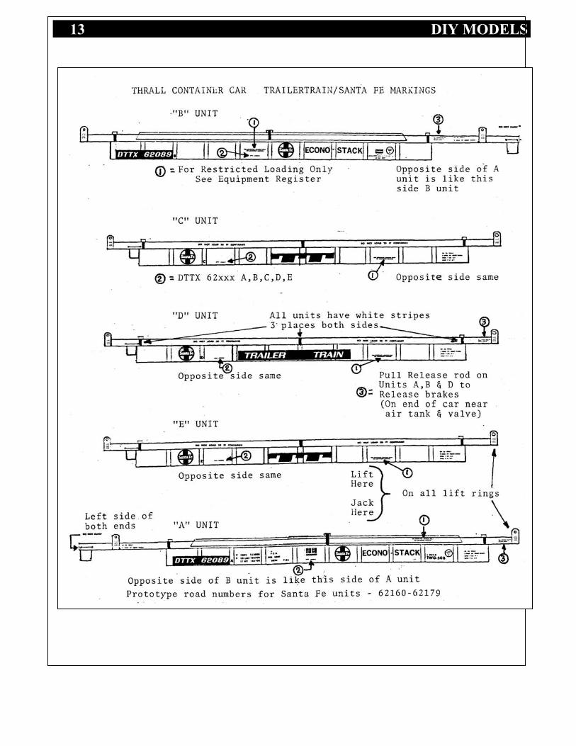
10. This should complete the unit(s) and painting and decaling remains. Floquil Light Blue is avery close match for the entire APL car with Floquil Platinum Mist for the tops of thewalkways. Prototype decals are available from Protopower Products. One sheet will do all fiveunits of the car.

6 DIY MODELS

7 DIY MODELS
Material for 2 End UnitsDes.
Qty. SizeStyrene sizesare for HOscale
40’Contnr.Length inscale feet
48’Contnr.Length inscale feet Description
A 4 .060 x .125 41’6” 49’6” Bottom frame side stripsB 10 .060 x .125 7’0” 7’0” Bottom frame cross piecesC 4 .l00 x .125 57’0” 64’0” Side sillsD 4 .040 x 2’3” 42’6” 50’7” Side panelsE 2 .040 x l-1/8 8’9” 8’9” Short platformsF 2 .040 x l-1/8 10’3” 10’3” Long platformsG 4 .040 x 3/8 9’0” 9’0” Well box endsH 2 .040 x .125 10’3” 10’3” Long platform end capsI 2 .020 x .125 10’3” 10’3” Short platform end capsJ 4 .015 x .188 9’6” 9’6” Bottom end plates – inside of wellK 36 - 44 .060 x .060 2’9” 2’9” Side panel braces
Detail Items – Refer to Drawings for Location
Item
Qty
. Size(decimal)
40’ Wellin
scale feet
48’ Wellin
scale feet Description4 .080 1’ 1’ Styrene triangular cross sect Load guides1 .030 x .040 8’ 3” 8’3” Brake chain bracket base
A/R .015 x .125 8’3” 8’3” Bracket sides.040 x .080 4’7” 4’7” Chain pulley material
5 .040 x .250 2’2” 2’2” Long walkway riser(tall)23 .040x .l00 2’10” 2’10” Short walkway riser(low)4 .030 x .l00 2’3” 2’3” Air tank pedestals2 Air tanks2 Air valves8 .015 x .125 2’10” 2’10” Equipment box sides8 .015 x .125 2’0” 2’0” Equipment box ends1 Brake wheel and stand1 .020 x .l00 3’0” 3’0” Lift ring plate material– cut, the round end, drill hole6 Ladder stock4 .040 x .188 9’9” 9’9” See-through walkway if you’re rich4 .015 x .060 33’6” 33’6” Top side sill braces4 .015 x .080 34’6” 34’6” Edge side sill braces1 3/8 x 2-56 screws Used with center truck2 ¼ x 2-56 screws Used with end trucks3 Trucks – Roller bearing type2 Coupler box & Couplers2 .125 x .250 Truck bolsters .125 x .250 x 8’9”
24 Grab irons - make from .015 music wire12 Stirrup steps make from .015 music wire1 8”pc .015 brass wire1 2” pcs .008 brass wire1 4” pcs. chain For brakes on “B” unit1 Brake Stand & Brake Wheel

8 DIY MODELS
Material for 3 Center Unit FramesDes.
Qty. Sizedecimal
40’ Well inscale feet
48’ Well inscale feet
Description
A 6 .060 x .125 41’6” 49’6” Bottom frame side stripsB 15 .060 x .125 7’0” 7’0” Bottom frame cross piecesC 6 .l00 x .125 49’6” 57’9” Side sillsD 6 .040 x 2’3” 42’6” 49’6” Side panelsE 6 .040 x l-1/8 8’9” 8’9” Short platformsG 6 .040 x 3/8 9’0” 9’0” Well box endsI 2 .020 x .125 10’3” 10’3” Platform end capsJ 4 .015 x .188 9’0” 9’0” Bottom end plates – inside of wellK 54 - 66
66.060 x .060 2’9” 2’9” Side panel braces
Detail Items – Refer to Drawings for Location
Item
No.
Qty
. Size(decimal)
40’ Wellin
scale feet
48’ Wellin
scale feet Description
6 .080 triangle? 1’ 1’ Styrene triangular cross sect Load guides6 .040 x .250 2’2” 2’2” Long walkway riser(tall)8 .040 x .l00 2’10” 2’10” Short walkway riser(low)2 .030 x .l00 3/16” 3/16” Air tank pedestals1 Air tanks – 1 on unit D1 Air valves – 1 on unit D6 .015 x .125 2’3” 2’3” Equipment box sides6 .015 x .125 2’0” 2’0” Equipment box ends1 .020 x .l00 3’0” 3’0” Lift ring plate material – cut, the round end, drill
hole6 Ladder stock6 .040 x .188 9’9” 9’9” See-through walkway if you’re rich – styrene
otherwise!4 .015 x .060 33’6” 33’6” Top side sill braces4 .015 x .080 34’6” Edge side sill braces4 3/8 x 2-56
screwsUsed with trucks
3 Trucks – Roller bearing type12 Grab irons12 Stirrup steps1 8”pc .015 brass wire1 Brake Stand1 Brake Wheel

9 DIY MODELS
Drawing 1

10 DIY MODELS
Drawing 2 – Deck Layouts

11 DIY MODELS

12 DIY MODELS
13 DIY MODELS

14 DIY MODELS
15 DIY MODELS