this tutorial will introduce to the basic steps of setting up a...
TRANSCRIPT
Top Down DesignTop-Down Design is a methodology that starts at the highest level of adesign concept and proceeds towards the lowest level. You start with thebroad project specification in mind and put that information in a centralizedlocation. Then you progress from this information to the individual parts.This makes it easy to design and manage large product assemblies. Youcan make changes from a central location that will propagate to all levels ofthe design
Creo Parametric provides us very powerful Top-Down Design tools. Ifimplemented properly, multiple design teams and designers can work on aproject concurrently and communicate design data easily and quickly, withfull confidence that all components will fit seamlessly into the final product.
Top-Down Design Tutorials have been developed to teach a user all thetools, Creo Parametric provides for implementing the Top-Down design.The self-study course starts from the very basic concepts and teachesadvanced concepts step by step. After completing these tutorials anEngineer or Designer will be able to start a real-world design project fromconcept and progress it to complete 3D definition. The tutorials are writtennot only from software point of view but great emphasis has been laid onthe implementation of the top-down design methodology to real products.
The training material is divided into sections. Each section is accompaniedwith exercises to practice the concepts learned. CAD models areaccompanied for the user practice. Finished models are also supplied tocompare the work done by the user.
Please click on the topic name to view more details.
1. Introduction2. Product Designing3. External References4. Managing External References5. External Copy Geometry6. Multi-Level Assembly7. Skeletons And Motion8. Family Table Of Skeleton9. Notebooks10.Derivative Models11.Conclusion
Prerequisites
The user should have basic concepts in thefollowing
1) Solid Modeling2) Surface Modeling3) Assembly
Stats
Total Pages: 495
Total Exercises: 28

INTRODUCTIONThis chapter will describe the Top-Down Design methodology andavailable tools in Creo Parametric to accomplish this. It alsocompares the Top-Down design with Bottom-Up design technique.
Typical workflow of Top-Down Design will be explained in theoryand also with the help of practical examples.
Ass
Assembly of Finished Components
Assembly of Finished Components
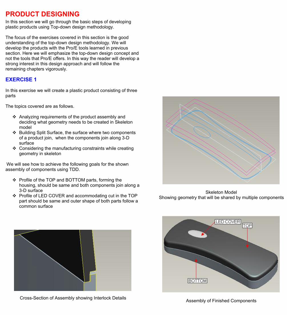
Cross-Section of Assembly showing Interlock Details
EXERCISE 1
In this exercise we will learn how to create a simple assembly ofparts that are driven by skeleton model.
The topics covered are as follows.
Creating Skeleton Assembling the components Using Copy Geometry feature to communicate references Creating model geometry
We will see how to achieve the following goals for the shownassembly of components.
Both components should be equal in length and width The shape of the mating surfaces should be same There should be two holes in each component; the
diameter of holes should be same and their axis aligned.
EXERCISE 2
In this exercise we will create a simple housing consisting of twoparts.
The topics covered are as follows.
Understanding what geometry needs to be created inSkeleton model
Using Publish Geometry and Copy Geometry features tocommunicate references
Creating model geometry by using references copied fromskeleton
Creating Interlock details in both components driven bygeometry in skeleton
We will see how to achieve the following goals for the shownassembly of components using TDD.
Profile of both components should be same Two rectangular holes in the side walls of the components
should be aligned and of same width.
PRODUCT DESIGNINGIn this section we will go through the basic steps of developingplastic products using Top-down design methodology.
The focus of the exercises covered in this section is the goodunderstanding of the top-down design methodology. We willdevelop the products with the Pro/E tools learned in previoussection. Here we will emphasize the top-down design concept andnot the tools that Pro/E offers. In this way the reader will develop astrong interest in this design approach and will follow theremaining chapters vigorously.
EXERCISE 1
In this exercise we will create a plastic product consisting of threeparts
The topics covered are as follows.
Analyzing requirements of the product assembly anddeciding what geometry needs to be created in Skeletonmodel
Building Split Surface, the surface where two componentsof a product join, when the components join along 3-Dsurface
Considering the manufacturing constraints while creatinggeometry in skeleton
We will see how to achieve the following goals for the shownassembly of components using TDD.
Profile of the TOP and BOTTOM parts, forming thehousing, should be same and both components join along a3-D surface
Profile of LED COVER and accommodating cut in the TOPpart should be same and outer shape of both parts follow acommon surface
Skeleton ModelShowing geometry that will be shared by multiple components
Assembly of Finished ComponentsCross-Section of Assembly showing Interlock Details

EXERCISE 2
In this exercise we will create a plastic housing for a remote-control consisting of four parts
The topics covered are as follows.
When should a designer define the complete skin of aproduct in skeleton
When should a designer apply drafts and rounds to thegeometry in skeleton
What geometry should not be created or merged inskeleton
Using the surfaces copied from the skeleton model tocreate solid geometry in components
We will see how to achieve the following goals for the shownassembly of components using TDD.
Profile of the TOP and BOTTOM parts, forming thehousing, should be same and both components join along a3-D surface
The elliptical cut at the front side should be of same sizeand shape in both parts.
Profile of BATTERY COVER and accommodating cut in theBOTTOM part is same and the outer shape of both parts(including underside and side) follow common surfaces
The round value is same for both parts
Skeleton ModelShowing complete skin, split surface and elliptical-cut surface
Assembly of Finished Components
Details of Emitter Hole and Elliptical cutBOTTOM and BATTREY COVER Components

EXERCISE 3
In this exercise we will create a plastic housing for a mobile phoneconsisting of three parts
The topics covered are as follows.
Defining the skin of the product by using advancedsurfacing techniques
Building the drafts into the surfaces that define the bodyshape
How to implement TDD for products having non-uniformthickness
When should a designer define the complete skin of aproduct in skeleton
Using surfacing techniques to hollow out parts having non-uniform thickness .
We will see how to achieve the following goals for the shownassembly of components using TDD.
Profile of the TOP and BOTTOM parts, forming thehousing, should be same and both components join along a3-D surface
Profile of LCD COVER and accommodating cut in the TOPpart is same and outer shape of both parts follow commonsurface
The round surfaces are shared by both (LCD COVER andTOP)
Incomplete Skeleton ModelShowing side and top surfaces
Assembly of Finished Components
Cross-Section of AssemblyComponent with Non-Uniform Thickness
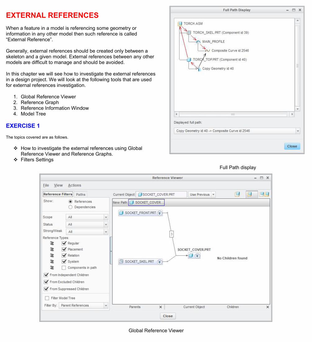
EXTERNAL REFERENCESWhen a feature in a model is referencing some geometry orinformation in any other model then such reference is called“External Reference”.
Generally, external references should be created only between askeleton and a given model. External references between any othermodels are difficult to manage and should be avoided.
In this chapter we will see how to investigate the external referencesin a design project. We will look at the following tools that are usedfor external references investigation.
1. Global Reference Viewer2. Reference Graph3. Reference Information Window4. Model Tree
EXERCISE 1
The topics covered are as follows.
How to investigate the external references using GlobalReference Viewer and Reference Graphs.
Filters SettingsFull Path display
Global Reference Viewer

EXERCISE 2
The topics covered are as follows.
How to investigate the external references of a componentwhen the parents are not in session.
Adding a column to the model tree to see the status of DataSharing Features
Global Reference Viewer-When the parents are not in session
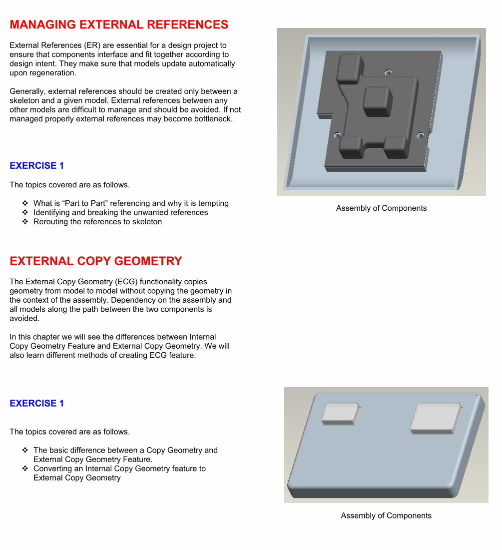
MANAGING EXTERNAL REFERENCESExternal References (ER) are essential for a design project toensure that components interface and fit together according todesign intent. They make sure that models update automaticallyupon regeneration.
Generally, external references should be created only between askeleton and a given model. External references between anyother models are difficult to manage and should be avoided. If notmanaged properly external references may become bottleneck.
Assembly of Components
EXERCISE 1
The topics covered are as follows.
What is “Part to Part” referencing and why it is tempting Identifying and breaking the unwanted references Rerouting the references to skeleton
EXTERNAL COPY GEOMETRYThe External Copy Geometry (ECG) functionality copiesgeometry from model to model without copying the geometry inthe context of the assembly. Dependency on the assembly andall models along the path between the two components isavoided.
In this chapter we will see the differences between InternalCopy Geometry Feature and External Copy Geometry. We willalso learn different methods of creating ECG feature.
EXERCISE 1
The topics covered are as follows.
The basic difference between a Copy Geometry andExternal Copy Geometry Feature.
Converting an Internal Copy Geometry feature toExternal Copy Geometry
Assembly of Components

EXERCISE 2
The topics covered are as follows.
Creating an External Copy Geometry feature in partmode
What models should be in memory to regenerate aCopy Geometry and External Copy Geometry Feature
Determining the dependency on parts and assembliesalong the path between a source and target component
Assembly of Components
EXERCISE 3
The topics covered are as follows.
How to create a reference pattern in a component byreferencing a pattern in the skeleton model. Skeleton Part Showing Pattern of Datum Points
Component Referencing the Pattern in Skeleton
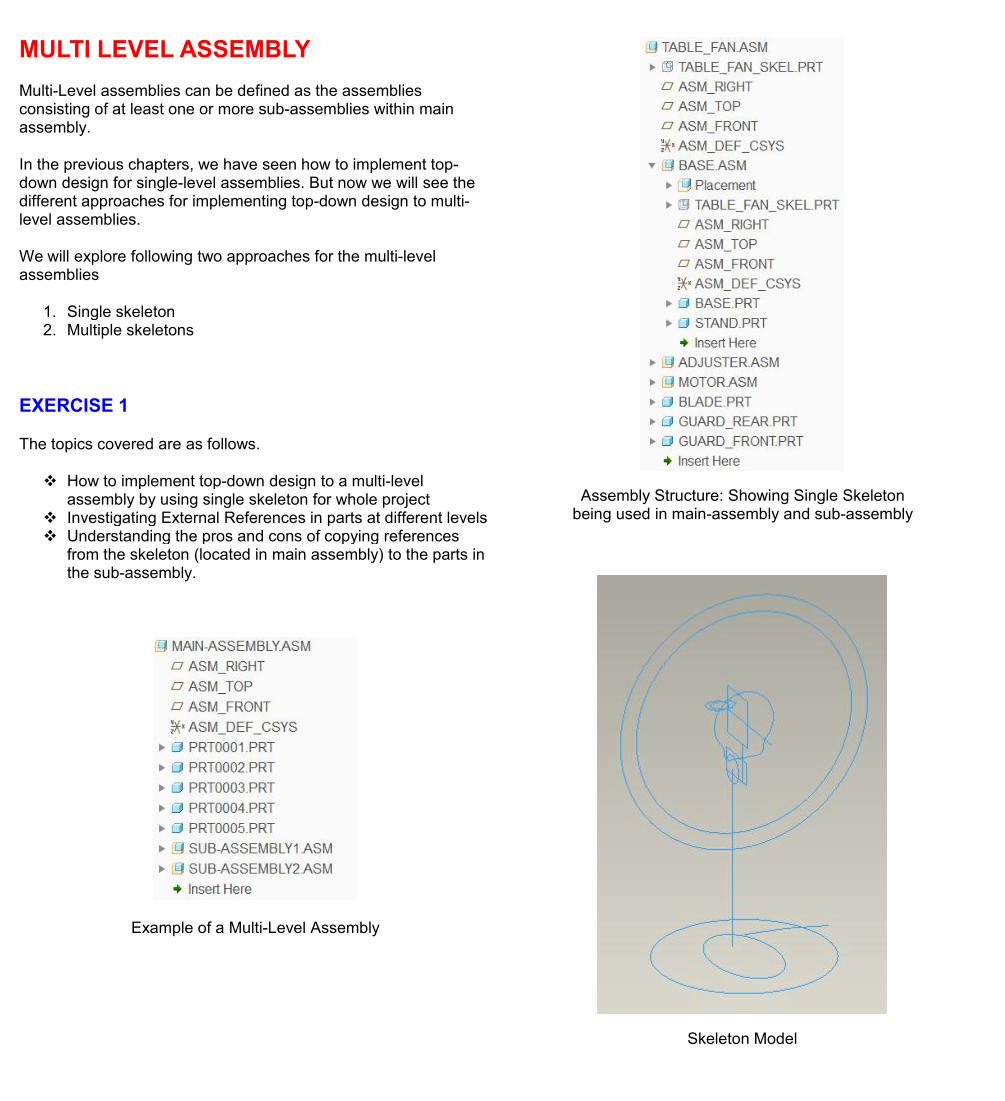
MULTI LEVEL ASSEMBLYMulti-Level assemblies can be defined as the assembliesconsisting of at least one or more sub-assemblies within mainassembly.
In the previous chapters, we have seen how to implement top-down design for single-level assemblies. But now we will see thedifferent approaches for implementing top-down design to multi-level assemblies.
We will explore following two approaches for the multi-levelassemblies
1. Single skeleton2. Multiple skeletons
EXERCISE 1
The topics covered are as follows.
How to implement top-down design to a multi-levelassembly by using single skeleton for whole project
Investigating External References in parts at different levels Understanding the pros and cons of copying references
from the skeleton (located in main assembly) to the parts inthe sub-assembly.
Example of a Multi-Level Assembly
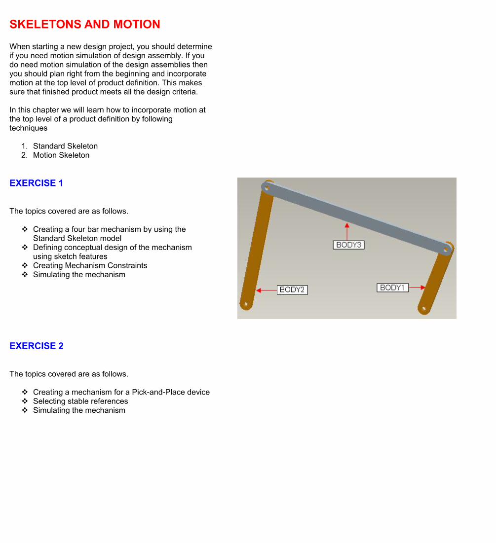
Assembly Structure: Showing Single Skeletonbeing used in main-assembly and sub-assembly
Skeleton Model

EXERCISE 2
The topics covered are as follows.
How to implement top-down design to a multi-levelassembly by using a separate skeleton at eachassembly level.
Creating skeletons in sub-assemblies Communicating the design information from skeleton to
skeleton Communicating the design information from skeleton to
components Deciding either to define features in main skeleton or
sub-assembly skeleton Investigating External References in parts at different
levels
Main-Assembly Skeleton
Assembly of Finished Components
SKELETONS AND MOTIONWhen starting a new design project, you should determineif you need motion simulation of design assembly. If youdo need motion simulation of the design assemblies thenyou should plan right from the beginning and incorporatemotion at the top level of product definition. This makessure that finished product meets all the design criteria.
In this chapter we will learn how to incorporate motion atthe top level of a product definition by followingtechniques
1. Standard Skeleton2. Motion Skeleton
EXERCISE 1
The topics covered are as follows.
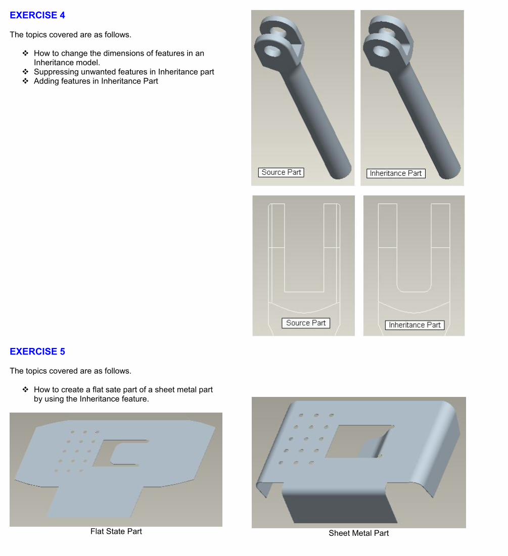
Creating a four bar mechanism by using theStandard Skeleton model
Defining conceptual design of the mechanismusing sketch features
Creating Mechanism Constraints Simulating the mechanism
EXERCISE 2
The topics covered are as follows.
Creating a mechanism for a Pick-and-Place device Selecting stable references Simulating the mechanism

A sample Pick-and-Place deviceCourtesy of Festo
EXERCISE 3
The topics covered are as follows.
How to simulate a mechanism in the sketcher Selecting stable references Simulating the mechanism

EXERCISE 4
The topics covered are as follows.
How to use the motion skeleton to incorporatemotion at the top level of a design project
Simulating the mechanism
FAMILY TABLE OF SKELETON
Skeleton models can maintain their own family tables.This means that assemblies can maintain differentskeleton instances across a family table.
This is a great way to create the multiple configuration ofan assembly driven by a skeleton.
EXERCISE 1
The topics covered are as follows.
How to use the family table of a skeleton model tocreate multiple configuration of a product.
Two Configurations of a Product Assembly

NOTEBOOKSA notebook can be described as an engineering notebookwhere we can define parameters and relations related to aproject. It maintains design intent in a central location.
Part and assembly models can both access theseparameters and information in a notebook.
EXERCISE 1
The topics covered are as follows.
How to create a notebook How to create parameters in the notebook by using
Parameters dialog box How to declare a notebook to the part models How to control dimensions in the parts by the
parameters in the notebook
EXERCISE 2
The topics covered are as follows.
How to import a 2D sketch in the notebook How to create parameters in the notebook by
defining global dimensions
EXERCISE 3
The topics covered are as follows.
How to implement the Top-Down design to anexisting assembly that was created using Bottom-Up approach
How to control location of components in theassembly by the parameters in the notebook.
Using the standard skeleton as PlacementSkeleton

DERIVATIVE MODELS
There may be situations when we may want to create aCAD model that is based on or has some relation to anexisting model. For example we may want to create a newpart for flat state of a sheet metal part or create a mirrorcopy of an existing part. For such derivative models Pro/Eprovides a number of tools. In this chapter we will discussthe following tools available
1. Merge Feature2. Inheritance Feature3. Shrinkwrap Feature4. Mirror Functionality
EXERCISE 1
The topics covered are as follows.
Creating a single component that represents theweldment of several components by using theMerge feature.
Investigating the external references created by aMerge feature
Assembly of Components
Weldment

EXERCISE 2
The topics covered are as follows.
Creating a single component that represents theweldment of several components by using theExternal Merge feature.
Investigating the external references created by anExternal Merge feature
Assembly of Components
Weldment
EXERCISE 3
The topics covered are as follows.
Creating an Inheritance model and suppressing theunwanted features.
Creating a casting model for a part that will requiredmachining operations later.
Finished Part
Casting Model
EXERCISE 4
The topics covered are as follows.
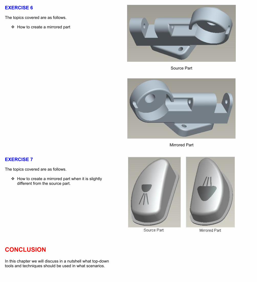
How to change the dimensions of features in anInheritance model.
Suppressing unwanted features in Inheritance part Adding features in Inheritance Part
EXERCISE 5
The topics covered are as follows.
How to create a flat sate part of a sheet metal partby using the Inheritance feature.
Flat State Part Sheet Metal Part
EXERCISE 6
The topics covered are as follows.
How to create a mirrored part
Source Part
Mirrored Part
EXERCISE 7
The topics covered are as follows.
How to create a mirrored part when it is slightlydifferent from the source part.
CONCLUSIONIn this chapter we will discuss in a nutshell what top-downtools and techniques should be used in what scenarios.