this manual was created using adobe acrobat · do not connect fp-x to the computer via usb cable...
TRANSCRIPT


IntroductionThank you for purchasing the FPWIN GR.
This Operational Guide Book was compiled with first -time users in mind, and explains how to set up the FPWIN GR software. It also contains an overview of how the software is operated. Please make sure you read it carefully and understand the contents before operating the software.
For more detailed information on using the software, please refer to the Help function.
For detailed information on instructions, please refer to the “Programming Manual”.

Table of Contents
Precautions before using this software .................................................................................. iv
Compatibility between the DOS version NPST-GR software and the FPWIN GR ................ v
Special precautions ................................................................................................................ vi
Special precautions for connecting to FP-X ........................................................................... vii
Additional Functions in Ver.2.................................................................................................. viii
1. Preparation and Overview ................................................. 1-1
1.1 Installing the Software ............................................................................ 1-2
1.2 Setting Up a Desktop Shortcut ............................................................... 1-7
1.3 Booting and Exiting the FPWIN GR ..................................................... 1-10
1.3.1 Booting the FPWIN GR......................................................................... 1-10
1.3.2 Exiting the FPWIN GR .......................................................................... 1-13
1.4 Connecting FP-X to the computer via USB cable................................. 1-14
2. Names of Parts and Basic Operation ............................... 2-1
2.1 FPWIN GR Screens and Menus ............................................................ 2-2
2.1.1 Names and Functions of Parts ............................................................... 2-2
2.2 Basic Operation of the FPWIN GR......................................................... 2-4
2.3 Program Conversion (Compile) .............................................................. 2-6
2.4 Online Editing and Offline Editing........................................................... 2-8
3. Creating and Editing Programs......................................... 3-1
3.1 Before Creating a Program .................................................................... 3-2
3.1.1 Booting the FPWIN GR and Selecting the Type of PLC......................... 3-2
3.1.2 Clearing Programs .................................................................................. 3-4
3.2 Creating Programs ................................................................................. 3-5
3.2.1 Inputting a Sample Program ................................................................... 3-5
3.2.2 Checking the Sample Program............................................................... 3-7
3.2.3 Returning to Program Before Edit (Quit Editing) .................................... 3-8
i

3.2.4 Undo / Redo............................................................................................ 3-8
3.2.5 Inputting Instructions not Found on the Function Bar........................... 3-12
3.2.6 Inputting High- level Instructions........................................................... 3-14
3.2.7 Continuing Input.................................................................................... 3-16
3.3 Correcting Programs ............................................................................ 3-19
3.3.1 Deleting Instructions and Horizontal Lines ........................................... 3-19
3.3.2 Adding Instructions ............................................................................... 3-19
3.3.3 Changing Relay Numbers and Timer Set Value................................... 3-20
3.3.4 Inserting Instructions............................................................................. 3-20
3.3.5 Inserting Rung....................................................................................... 3-20
3.3.6 Deleting Rung ....................................................................................... 3-21
3.4 An Introduction to Other Functions....................................................... 3-22
3.4.1 Changing Devices................................................................................. 3-22
3.4.2 Shifting X and Y by Word...................................................................... 3-24
3.4.3 Changing PLC Types............................................................................ 3-26
4. Transmitting Programs...................................................... 4-1
4.1 Sending a Program to the PLC .............................................................. 4-2
4.2 Verifying Programs................................................................................. 4-5
4.3 Totally Check Program Function ............................................................ 4-6
4.4 Starting and Stopping Monitoring ........................................................... 4-7
4.5 Monitoring Registers .............................................................................. 4-8
4.6 Monitoring Relays................................................................................. 4-11
4.7 Forced Input and Output ...................................................................... 4-14
4.8 Status Display ...................................................................................... 4-18
5. Saving a Program............................................................... 5-1
5.1 Saving a Program................................................................................... 5-2
6. Printing a Program ............................................................. 6-1
ii

6.1 Printing a Program ................................................................................. 6-2
6.1.1 Printing.................................................................................................... 6-2
6.1.2 Setting the Printing Style......................................................................... 6-2
7. Inputting Comments........................................................... 7-1
7.1 An Overview of Comments..................................................................... 7-2
7.2 I/O Comments ........................................................................................ 7-6
7.3 Block Comments .................................................................................... 7-8
7.4 Remarks ................................................................................................. 7-9
8. Searches ............................................................................. 8-1
8.1 Device Searches .................................................................................... 8-2
8.2 Instruction Searches............................................................................... 8-3
8.3 Comment Searches................................................................................ 8-4
8.4 Address Jumps....................................................................................... 8-5
8.5 Cross Reference .................................................................................... 8-6
9. Menu Tables........................................................................ 9-1
9.1 Menu Tables........................................................................................... 9-2
9.2 Function Bars ....................................................................................... 9-10
9.3 Tool Bar List ......................................................................................... 9-21
10. Precautions Concerning Usage ...................................... 10-1
10.1 What Do I Do If ... ?.............................................................................. 10-2
iii
Precautions before using this software
This Operational Guide Book was compiled with first -time users in mind, and explains how to set up the FPWIN GR. It also contains an overview of how the software is operated. For more detailed information on using the software, please refer to the Help function. For detailed information on instructions, please refer to the “Programming Manual”.
How programs are input
The FPWIN GR has three editing modes: “Ladder Symbol”, “Boolean Ladder”, and “Boolean Non- ladder”. This guide book focuses on the “Ladder Symbol” method in the explanations of the programming and editing functions.
Usage environment and types of PLCs that are supported
Please check the environment in which the FPWIN GR can be used.
Usage environment conditions:
Operating system ...................................Windows® 95 (OSR2 or later)/ Windows® 98SE/ Windows® Me/ Windows® 2000/ Windows NT® (Ver. 4.0 or later)/ Windows® XP
Required hard disk capacity ...................At least 40MB
Recommended CPU ..............................Pentium 100MHz or higher
Recommended installed memory...........64MB or more (depend on OS)
Recommended screen resolution...........800 x 600 or higher
Recommended display colors ................High Color (16- bit or higher)
Applicable PLC types
All FP series types are supported: FP0, FP SIGMA, FP-e, FP-X, FP1, FP-M, FP2, FP2SH, FP3, FP10SH
Regarding Account for Windows® 2000/ Windows® XP
[When installing] Make sure to install with the authorized account of Administrators (computer-system managers).
[When starting up and operating]
The accounts which enables start-up and operations are Administrator or Power User only. Please note that communication is not available if logging on with the account of User or Guests.
CAUTION
In order to connect FP-X via USB cable, the computer must be equipped with
USB port and Operating System is limited to one (Windows® 98SE,
Windows® Me, Windows® 2000, Windows® XP) corresponding to USB.
It is necessary to install FPWIN GR Ver.2.5 or higher before the computer is
connected with FP-X.
iv

v
Compatibility between the DOS version NPST-GR software and the FPWIN GR
There are some areas which differ between the conventional DOS version software of the NPST-GR and the FPWIN GR. Please check the contents listed below carefully.
File compatibility
Files created with the NPST-GR Ver. 4 or Ver. 3 can be loaded (including I/O comments, remarks and block comments).
Files created with the FPWIN GR can be saved as NPST-GR files, but without the comments.
When programs and comments created with the FPWIN GR are downloaded to the PLC, comments cannot be loaded with the NPST-GR, but programs can be loaded.
Operation and function compatibility
There are no merge registration or loading functions. Instead, the Copy and Paste functions in Windows® should be used.
Verifications cannot be carried out targeting files. The files to be verified must first be loaded, and then verified.
There are no multi - point monitoring or multi -data monitoring functions.
The network status cannot be displayed on the online status display.
Programs transferred to the IC card in the FPWIN GR format cannot be read by NPST-GR.
Opening NPST-GR files
When loading conventional NPST-GR files from a disk, select “NPST-GR File (*.spg)” from the drop-down list under “Files of type”, as shown at the left.

vi
Special precautions
Deleting programs
Before inputting programs in the PLC, always carry out the “Clear Program” operation.
[Clearing Program] Section 3.1.2
A note about saving programs
To ensure that programs are not accidentally lost, we strongly recommend that users follow the precautions listed below.
Hard copies should be created.
In case programs are lost, or files are destroyed or accidentally overwritten, the contents of the program should always be printed out and a hard copy stored somewhere for future use.
Passwords should be carefully specified.
The password setting is designed to prevent accidental overwriting of data, but if the password is forgotten, it makes it impossible to overwrite programs. Also, if a password is compulsorily canceled, the program will be deleted. When setting passwords, make sure they are written down in the specifications manual or another secure location.
ROM versions of programs should be created.
To prevent programs from being lost if the backup battery runs down, or accidentally overwritten at the workplace site, we recommend making a ROM copy of programs input to the RAM. If the PLC is being used over a long period of time, or if the program is being incorporated into the device before being shipped, this is especially important.
Special precautions for connecting to FP-X
Necessary installing FPWIN GR Ver.2.5 or higher
Before connecting to FP-X to the computer, it is necessary to install FPWIN GR Ver.2.5 or higher.
Regarding installation, please refer to Section 1.1.
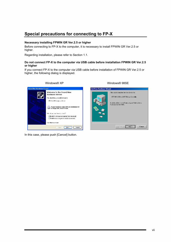
Do not connect FP-X to the computer via USB cable before installation FPWIN GR Ver.2.5 or higher
If you connect FP-X to the computer via USB cable before installation of FPWIN GR Ver.2.5 or higher, the following dialog is displayed.
Windows® XP Windows® 98SE
In this case, please push [Cancel] button.
vii

Additional Functions in Ver.2
1 Display screens offer greater flexibility
Window positions and sizes can be stored in the memory
The positions and sizes of the various windows, including the program editing screen, the relay monitor screen and the register monitor screen, can now be stored in the memory. In addition, when programs are read, the relay monitor screen and register monitor screen can now be displayed at the same time that the editing screen is displayed.
- To store window positions and sizes in the memory, select “Keep Window Position” on the “Option” menu. After this is done, the various windows are displayed at the positions and in the sizes stored in the memory.
- To select the screen to be displayed when the program is read, select ”Configuration” on the “Option” menu. Under the “Default Editing View” item displayed in the dialog box, turn on the check box for the screen to be displayed.
Remarks can be displayed to the right of the ladder bus
“I/O Comments” and “Remarks” can now be edited in the comment display bar, and remarks can be displayed to the right of the ladder bus line on the editing screen.
2 Search functions expanded
Detailed search of devices being used
Detailed searches can now be carried out using “Used I/O List...” and “Cross Reference...”.
In a program like that shown below, previously only the DT0 and FL0 would have been recognized as devices in use. Using the “Detailed Search” function included in Ver.2, however, DT0 to DT9 and FL0 to FL9, which are actually being used, can be recognized as devices in use. This enables devices not being used to be identified more accurately.
viii

3 Program flow easy to understand at a glance
Pair instruction map function
A “Pair Instruction Map” function has been added that displays instructions that determine the flow of the program, such as MC/MCE, JP/LBL, and CALL/SUB/RET, in pairs, as a list, making it easy to see the overall flow of the program at a glance. This is very helpful in analyzing not only programs put together by the user, but programs created by others as well.
To access the pair instruction map function, select “Pair Instruction Map” on the “Search” menu.
Block comment list function
A new function has been added that lets block comment in the program be displayed as a list. The list display of block comment lets the user search for a target routine quickly and easily.
The block comment list function is accessed by selecting “Block Comment List” on the “Comment” menu.
4 Smoother testing and debugging
Forcible input/output devices can be stored in the memory
Now, even if the forcible mode has been canceled using “Force Input/Output”, devices that have already been registered can be stored in the memory.
I/O list can be loaded when devices are changed
It is now possible to load the “Used I/O List...” from the “Change Device” dialog box.
Automatic error discrimination function
If an operation error occurs in a PLC during programming or debugging, a status display dialog box is displayed automatically. This can be used to check the contents of the self -diagnosis error.
If an operation error occurs, the error address can be confirmed in the dialog box. Click on “Clear Error” button to clear the error.
To display the status, select “Status Display” on the “Online” menu.
If a syntax error occurs, the total check function is launched automatically. Check the contents of the error using this function.
ix
5 User- tailored environment settings can be specified
The user can store individually tailored environments in the memory and bring them back later
The user can store his or her preferred environment tools in the memory and reproduce them as needed. Thus, if multiple users are sharing a single computer, each can store his or her own preferred tool environment and access it at any time.
[Elements that can be custom- tailored]
- Positions of tool bars, comment display bars, input field bars, entry bars, and ten-key bars
- Levels and positions at which function bars are displayed
- Zoom settings, text point settings, and various display color settings
- All operation environment settings and all types of customized settings
To store individual environments in the memory and bring them back later, select “Private Configuration” on the “Option” menu.
Customization function provided for right - click menu
The menus displayed when the right button of the mouse is clicked can now be customized. This enhances overall operation by letting the user, for example, launch the comment input function or minimize mouse pointer movements by clicking with the right button of the mouse. (These settings are saved in the individual environment settings described above.)
To customize right - click menus, select “Right- click Menu” on the “Customize” menu under “Option”.
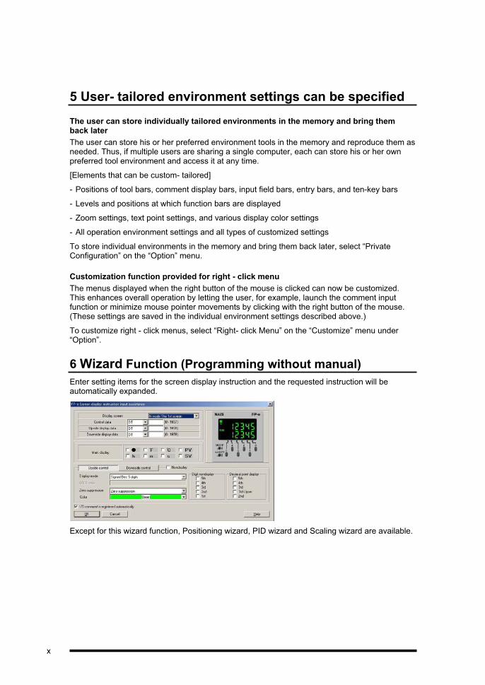
6 Wizard Function (Programming without manual)
Enter setting items for the screen display instruction and the requested instruction will be automatically expanded.
Except for this wizard function, Positioning wizard, PID wizard and Scaling wizard are available.
x
7 Text Input Mode
In the Ladder Symbol View Mode, Boolean Ladder View Mode, and Boolean Non-ladder View Mode, nimonic codes from the keyboard can be used in preference to the instruction entry with the function key (This is called as [Text input mode].).
To use Text input mode, select “Text input mode priority” on the “Edit” menu or click Button.
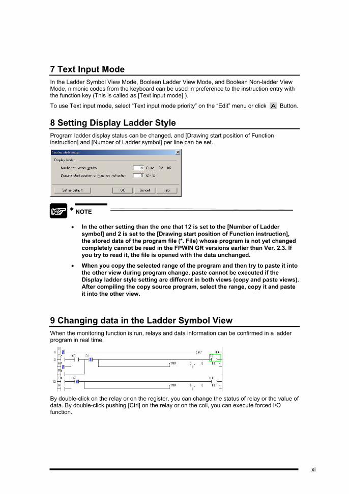
8 Setting Display Ladder Style
Program ladder display status can be changed, and [Drawing start position of Function instruction] and [Number of Ladder symbol] per line can be set.
NOTE
In the other setting than the one that 12 is set to the [Number of Ladder
symbol] and 2 is set to the [Drawing start position of Function instruction],
the stored data of the program file (*. File) whose program is not yet changed
completely cannot be read in the FPWIN GR versions earlier than Ver. 2.3. If
you try to read it, the file is opened with the data unchanged.
When you copy the selected range of the program and then try to paste it into
the other view during program change, paste cannot be executed if the
Display ladder style setting are different in both views (copy and paste views).
After compiling the copy source program, select the range, copy it and paste
it into the other view.
9 Changing data in the Ladder Symbol View
When the monitoring function is run, relays and data information can be confirmed in a ladder program in real time.
By double-click on the relay or on the register, you can change the status of relay or the value of data. By double-click pushing [Ctrl] on the relay or on the coil, you can execute forced I/O function.
xi
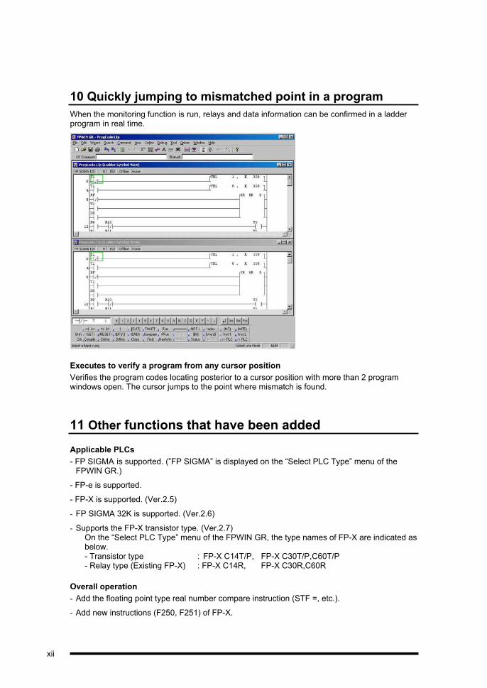
10 Quickly jumping to mismatched point in a program
When the monitoring function is run, relays and data information can be confirmed in a ladder program in real time.
Executes to verify a program from any cursor position
Verifies the program codes locating posterior to a cursor position with more than 2 program windows open. The cursor jumps to the point where mismatch is found.
11 Other functions that have been added
Applicable PLCs
- FP SIGMA is supported. (”FP SIGMA” is displayed on the “Select PLC Type” menu of the FPWIN GR.)
- FP-e is supported.
- FP-X is supported. (Ver.2.5)
- FP SIGMA 32K is supported. (Ver.2.6)
- Supports the FP-X transistor type. (Ver.2.7) On the “Select PLC Type” menu of the FPWIN GR, the type names of FP-X are indicated as below. - Transistor type : FP-X C14T/P, FP-X C30T/P,C60T/P - Relay type (Existing FP-X) : FP-X C14R, FP-X C30R,C60R
Overall operation
- Add the floating point type real number compare instruction (STF =, etc.).
- Add new instructions (F250, F251) of FP-X.
xii

- Add new instructions (F4, F161, F230, F231, F354) of FP2/2SH.
- You can copy & paste by rectangle mode.
- Menus displayed by clicking the right button of the mouse can now be customized. (“Option” “Customize” “Right-click Menu”)
- Individual operating environments can be saved and brought back. (“Option” “Private Configuration”)
- The active program can now be switched with a single click. (“Window” “Switch Program”)
- Settings for the monitor interval and the default display window have been added under “Configuration”.
- The setting for the symbol width included under the “Configuration” in previous versions has been moved to “View Settings” on the “View” menu. Comment fonts can now also be specified using “View Settings”.
- Added Text input mode. You can edit program by entering a character from a keyboard.
- You can design the start position of High-Level instruction. So, it is possible to display Maximum 5 contacts on the left side of High-Level instruction.
- Support [Undo] and [Redo] function.
- You can enter I/O comment simultaneously after inputting instruction.
- You can compile the program, even if the cursor is in the position of operand of High-Level instruction.
- Added SCAL/DSCAL/FSCAL instructions in [Wizard] function.
Printing
- “Print Style Setup” can now be used to specify comment fonts. If the comment font is specified using “Depend on View Settings”, the printed output will appear exactly like the ladder displayed on the screen. The user can also now specify whether or not a background color will be used with block comments.
- You can print ladder list by color.
xiii

Online mode
- When downloading or uploading program, you can specify Station No. or Communication Setting. (Ver.2.5)
- A “Security Information” function has been added under “Tool” menu. (Ver.2.5)
- A “Upload Settings” function has been added under “Tool” menu. (Ver.2.5)
- A “Monitoring PC Link” item has been added under “Status Display”.
- SSTP instruction can now be monitored either on the editing screen or on the relay monitor.
- The widths of the various columns in the “Monitoring Registers” window can be changed and stored in the memory.
- I/O comments and remarks can now be input in the “Comment Display Bar”.
- Two supplementary lines can be drawn under “Time Chart Monitor”.
- You can synchronize the monitoring of Editing View and Data/Relay Monitor.
- In Monitoring Registers and Forced I/O, you can register only used device.
- In Monitoring Registers, you can change the value without pushing the [Enter] key.
- In Monitoring Relays, the default status is reversal of the present status.
- In Forced I/O, you can change the forced status by shortcut key and change the width of dialog.
Other additions
- The “MEWNET-H” settings software is now included with the program.
- The “FP series Programmable Controllers Programming Manual” is included in PDF file format.
- “MEWNET-W2 settings” function is included.
- [Data Editor] supported Data Memory Expansion unit.
- You can change number of column of [Data Editor].
- “MCU settings” function is included.
xiv

Chapter 1
Preparation and Overview

1.1 Installing the Software
Installing the software on a personal computer
The FPWIN GR should be installed on a personal computer, following the procedure outlined below.
1. Exit any applications currently running.
If there are any applications currently running, exit them.
2. Set the setup CD in place.
Insert the FPWIN GR setup CD in the CD drive.
3. Select “Run...”.
Either click on the “Start” button at the lower left of the screen, or press [CTRL] + [ESC] keys to display the Windows® menu, and select “Run...”.
CAUTION
In order to connect FP-X to the computer via USB cable, the computer must
be equipped with Windows® 98SE, Windows® Me, Windows® 2000,
Windows® XP. Before connecting to FP-X to the computer, it is necessary to
install FPWIN GR Ver.2.5 or higher
Make sure to install with the authorized account of Administrators
(Computer-system managers), when you install this software.
The computer in which the FPWIN GR is being installed must have at least 40
MB of hard disk space available.
The above instructions assume that Windows® is installed on the C drive,
and that the CD drive is the D drive. If the drives are different, or if the
program is being installed through a network, enter the appropriate drive
names based on the relevant operating environment.
next page
1-2

4. Enter the name of the file to be run.
When “Run...” is selected, the dialog box shown
at the left appears. Enter d:\setup.exe and click
on “OK” button.
NOTE: The drive name (d:) may vary depending on the computer operating environment.
5. A confirmation message is displayed.
The setup program is booted and a confirmation message is displayed. Check the contents and click on “Next >” button. To interrupt the operation, click on the “Cancel” button.
6. Confirm the licensing agreement.
A dialog box is displayed in which the licensing agreement can be confirmed. To indicate agreement with all of the licensing items, click on the “Yes” button. The setup process begins. Selecting “No” cancels the FPWIN GR setup procedure.
7. Register your user information.
A user information dialog box is displayed. Fill in the data for the “Name”, “Company Name”, and “Serial No.” items, and click on “Next >”.
The serial number is printed on the user card included in the FPWIN GR package. Make sure it is entered correctly.
The information entered here can be confirmed on the splash screen when the FPWIN GR is booted, and under “About” in the “Help” menu.
1-3

8. Select the destination to which the program is to be installed.
A confirmation dialog box is displayed, showing the folder in which the program is to be installed. To install the program in the displayed folder, click on the “Next >” button.
The folder displayed from the beginning, “c:\Program Files\Panasonic MEW Control\FPWIN GR”, may be used. To install the program in a different folder, click on the “Browse...” buttonand specify a folder.
9. Select the component, which is to be installed.
Select the component, which is to be installed.
If you want to install all compo, please push [Next] button.
10. Select the program folder.
A confirmation dialog box is displayed, showing the program folder. To use the displayed folder, click on the “Next >” button.
The “Panasonic MEW Control” folder displayed from the beginning may be used. To change to a different folder, enter the name of the folder.
next page
1-4

11. The installation begins.
A message is displayed on the screen, indicating that installation is in progress, and the FPWIN GR setup begins.
12. When installing in Windows® XP, the following dialog is displayed 2 times. If operating system is not Windows® XP, the following dialog is not displayed. In this case, please jump next step.
USB driver, which is needed to connect FP-X to the computer via USB cable, will be installed.
Please select [Continue Anyway] button.
13. Description for Adobe Acrobat Reader is displayed.
If you need, please install from CD.
14. Confirm the Readme file display.
When the setup process is finished, a dialog box is displayed, indicating that the setup has been completed.
To display the Readme file, click on the “Yes” button.
1-5

15. Confirm rebooting of the computer.
When the entire process has been completed, a dialog box is displayed, indicating that the computer should be rebooted. Select either the “Yes, I want to restart my computer now” button, or the “No, I will restart my computer later” button, and click on the “Finish” button.The computer must be rebooted before the FPWIN GR can be used, so rebooting is recommended at this point.
16. The FPWIN GR group icon is displayed.
If the setup process is concluded without rebooting the computer, the FPWIN GR group icon is displayed on the computer.
To boot the FPWIN GR, click on the group icon.
REFERENCE
The group icon mentioned above is displayed only when the installation has just
been completed. For information on booting the program, see section 1.3
“Booting and Exiting the FPWIN GR”, and section 1.2 “Setting Up a Desktop
Shortcut”.
CAUTION
Never remove the CD while the installation is in progress.
From version 2.5, install folder is changed to '\Program Files\Panasonic MEW
Control\FPWIN GR 2', and group folder is changed to 'Panasonic MEW
Control\FPWIN GR 2'.
1-6

1.2 Setting Up a Desktop Shortcut
If an icon called “Shortcut to FPWIN GR” is created on the desktop, the FPWIN GR can be booted simply by double-clicking on that icon. This is faster and simpler than the usual booting procedure.
The FPWIN GR shortcut icon is not automatically created as part of the usual installation process. To create the icon, follow the procedure below.
1. Select the shortcut creation menu.
Without selecting any icon, click the right button of the mouse on the desktop.
Then select “New” and “Shortcut” from the menu.
2. Enter the file name.
When the shortcut creation menu is selected, a dialog box like that shown at the left is displayed, so that the file name can be input.In our explanation, we will proceed by clicking the “Browse...” button.
next page
1-7

3. Search for the FPWIN GR file.
Clicking on the “Browse...” button displays the file reference dialog box shown at the left.
Open the folders in the following order: [Program Files] [Panasonic MEW Control]
[FPWIN GR2].
4. Select the FPWIN GR file.
Select the installed FPWIN GR file, either by clicking on “Open” button, or double-clicking with the mouse.
5. Click on the “Next >” button.
When the FPWIN GR is selected, the dialog box where the file name is input appears again. Click on the “Next >” button to proceed.
next page
1-8

6. Select the name of the shortcut.
Select a name to be displayed beneath the shortcut icon, and click on the “Finish” button.
The name “FPWIN GR”, which is displayed from the beginning, may also be used. To change to another name, enter that name.
7. This completes creation of the shortcut icon.
You have now finished creating your shortcut icon to be displayed on the desktop.
If the procedure has been successfully completed, the icon showed at the left will be displayed. Double-clicking on this icon boots the FPWIN GR.
1-9
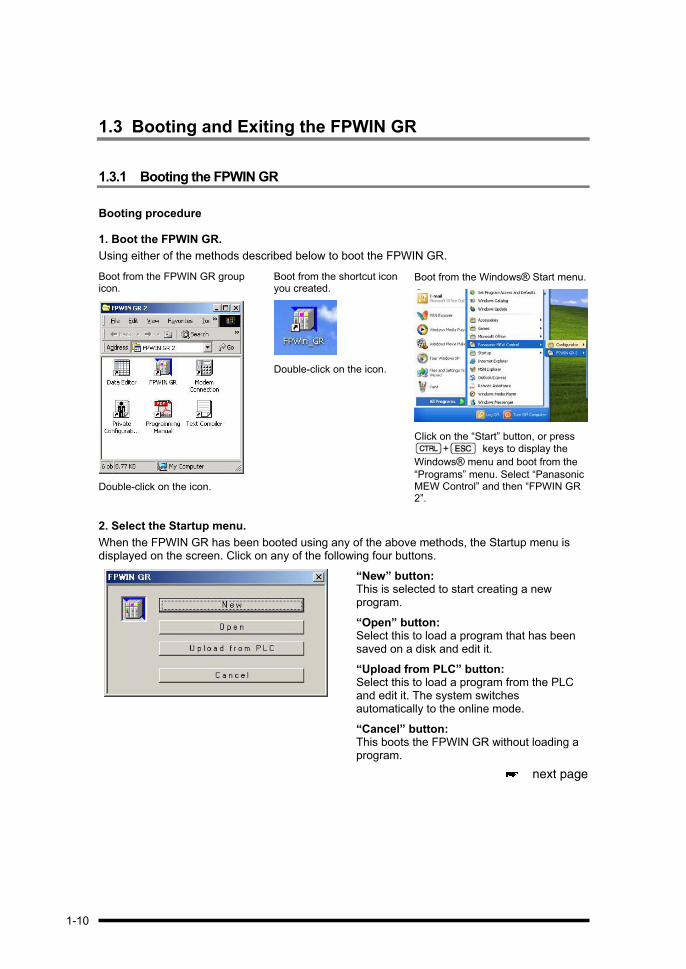
1.3 Booting and Exiting the FPWIN GR
1.3.1 Booting the FPWIN GR
Booting procedure
1. Boot the FPWIN GR.
Using either of the methods described below to boot the FPWIN GR.
Boot from the FPWIN GR group icon.
Double-click on the icon.
Boot from the shortcut icon you created.
Double-click on the icon.
Boot from the Windows® Start menu.
Click on the “Start” button, or press
+ keys to display the
Windows® menu and boot from the
“Programs” menu. Select “Panasonic MEW Control” and then “FPWIN GR 2”.
2. Select the Startup menu.
When the FPWIN GR has been booted using any of the above methods, the Startup menu is displayed on the screen. Click on any of the following four buttons.
“New” button:This is selected to start creating a new program.
“Open” button: Select this to load a program that has been saved on a disk and edit it.
“Upload from PLC” button: Select this to load a program from the PLC and edit it. The system switches automatically to the online mode.
“Cancel” button: This boots the FPWIN GR without loading a program.
next page
1-10

2- 1. If “New” was selected, select the type of PLC to be used.
If “New” was selected on the Startup menu, a dialog box is displayed on the screen, showing the types that can be selected. Select the type of PLC being used, and click on the “OK”button.
2- 2. If “Open” was selected, a data file is opened.
If “Open” was selected on the Startup menu, a dialog box is displayed on the screen, showing the files that can be opened. Select the file to be edited and double-click on it with the mouse, or click on the “OK” button.
next page
1-11

2- 3. If “Upload from PLC” was selected, data is loaded from the PLC.
If “Upload from PLC” was selected on the Startup menu, a dialog box is displayed on the screen, confirming that data is to be uploaded. Click on the “Yes” button.
Uploading of the program begins. If all of the data is uploaded successfully, a dialog box is displayed confirming the change in the PLC mode. To change to the RUN mode, click on the “Yes” button.
3. The initial FPWIN GR screen is displayed.
If the FPWIN GR is booted normally, the initial screen shown below is displayed.
1-12
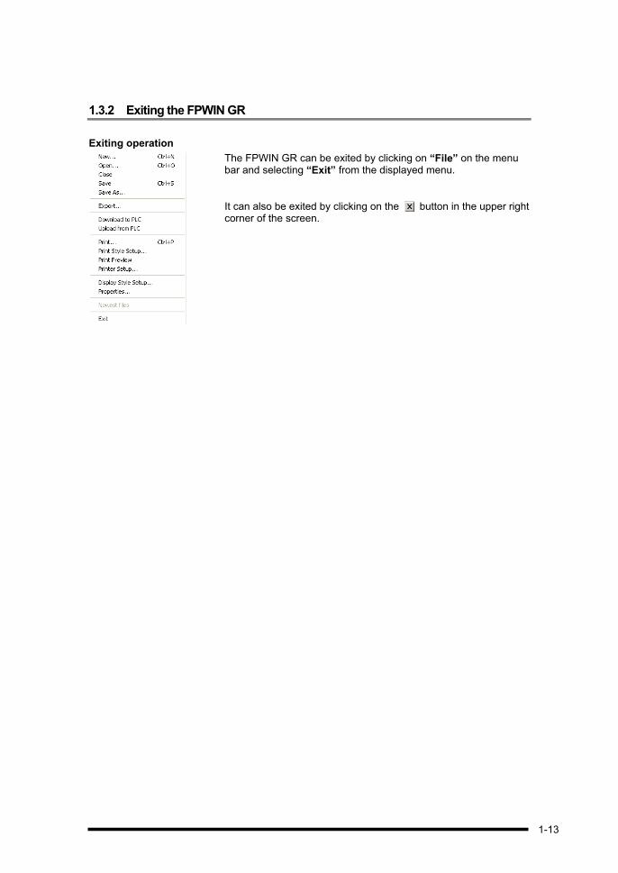
1.3.2 Exiting the FPWIN GR
Exiting operation
The FPWIN GR can be exited by clicking on “File” on the menu bar and selecting “Exit” from the displayed menu.
It can also be exited by clicking on the button in the upper right corner of the screen.
1-13

1.4 Connecting FP-X to the computer via USB cable
Necessary installing FPWIN GR Ver.2.5 or higher
Before connecting to FP-X to the computer, it is necessary to install FPWIN GR Ver.2.5 or higher.
Regarding installation, please refer to ‘1.1.Installing the Software’.
When you connect FP-X to the computer via USB cable after installing FPWIN GR Ver.2.5 or higher
In this case, it is necessary to install USB driver.
USB drive is copied under \Program Files\Panasonic MEW control\FP-X USB.
If your operating system is Windows® ME or Windows® 2000, USB driver is automatically installed, but your operation system is Windows® 98SE or Windows® XP, the following dialog is displayed.
Windows® XP Windows® 98SE
If your operating system is Windows® XP, please select [Install the software automatically (Recommended)], and push [Next] button. Along the way, right dialog is displayed 2 times. Then, please select [Continue Anyway] button.
If your operation system is Windows® 98 SE, please select [Search for the best driver for your device (Recommended)]. After then, select [Specify a location] and specify “c:\Program Files\Panasonic MEW Control\FP-X USB” on right dialog.
1-14

Select C-NET(RS232C) as network type in Communication Settings.
When you connect FP-X via USB cable, please select C-NET(RS232C) as Network type.
Please confirm the specified COM port by the following way.
1. At first, connect FP-X to the computer via USB cable.
2. Display Device Manager by the following way.
- In case of Windows® 98SE
[My computer] -> [Control panel] -> [System] -> Click [Device Manager] tab -> Select [View devices by type]
- In case of Windows® Me
[My computer] -> [Control panel] -> [View all Control Panel options] -> [System] -> Click [Device Manager] tab -> Select [View devices by type] tab
- In case of Windows® 2000
[My computer] -> [Control panel] -> [System] -> Click [Hardware] tab -> Click [Device Manager] button -> Click [View] menu -> [Device by type]
- In case of Windows® 2000/ Windows® XP
[My computer] -> [View System information] -> Click [Hardware] tab -> Click [Device Manager] button -> Click [View] menu -> [Device by type]
3. If [CP201x USB to UART Bridge Controller (COM3)] is displayed in Ports (COM&LPT), please specify 3 as port No.
When it is not possible to communicate with FP-X
There is a possibility that the USB driver is not normally installed.
After you connects the computer with FP-X by using the USB cable, please right-click in "CP2101 USB to UART Bridge Controller" to which '?' mark has adhered, and delete it.
Afterwards, please disconnect and connect the USB cable again, and install the driver while referring to the former page.
1-15

1-16

Chapter 2
Names of Parts and Basic Operation
2.1 FPWIN GR Screens and Menus
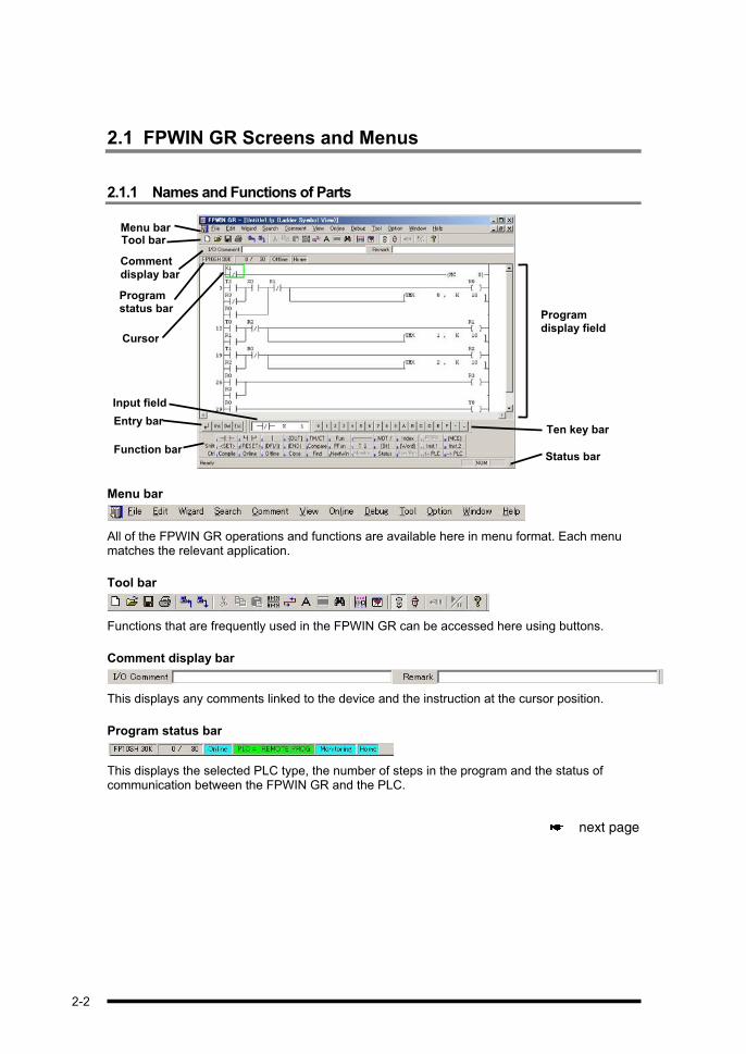
2.1.1 Names and Functions of Parts
Menu bar Tool bar
Comment
display bar
Program status bar
Cursor
Program
display field
Function bar
Input field
Entry barTen key bar
Status bar
Menu bar
All of the FPWIN GR operations and functions are available here in menu format. Each menu matches the relevant application.
Tool bar
Functions that are frequently used in the FPWIN GR can be accessed here using buttons.
Comment display bar
This displays any comments linked to the device and the instruction at the cursor position.
Program status bar
This displays the selected PLC type, the number of steps in the program and the status of communication between the FPWIN GR and the PLC.
next page
2-2

Status bar
This shows the operation status of the FPWIN GR.
Function bar
When a program is input, instructions and functions can be selected using the mouse and the function keys located here.
Entry bar
The [Enter], [Ins], [Del], and [Esc] keys can be input here using the mouse.
Ten key bar
Numeric values 0 to 9, letters A to F, and other values can be entered here, using the mouse.
Input field
Normally, this displays instructions and operands at the cursor position. When a program is being edited, it displays instructions and operands currently being edited.
2-3

2.2 Basic Operation of the FPWIN GR
Cursor
The cursor can be moved within the program display field, using the four arrow keys ( , , , ) and by clicking the mouse. Instructions input using the function bar are input at this cursor position.
Cursor The cursor can be movedwithin the program displayfield, using cursor keys
The key can be used to move the cursor to the beginning of the line, and the key to move it to the end of the line.
The + keys can be used to move the cursor to the beginning of the program, and the + keys to move it to the last line of the program.
Windows
With the FPWIN GR, multiple program windows can be opened.
The various windows can be moved using the + keys, or the + keys.
2-4

Inputting instructions
When programming, instructions can be input by clicking the mouse on the function bar, or by using the to function keys in conjunction with the and keys. The function bar display changes based on the program input conditions, as shown below. Instructions are input at the cursor position in the program display field.
Instruction input keys (initial display)
When an index register has been input
When a comparison instruction has been input
When a timer or counter instruction has been input
When the high- level instruction or similar instruction has been input
When a contact or coil has been input
CAUTION
When inputting instructions using + keys or + keys, please be
aware that there are some PLC types which do not support the displayed
instructions. Check the programming manual for PLC types which do support the
instructions.
2-5

2.3 Program Conversion (Compile)
An overview of the program conversion (compile)
In the Ladder Symbol View mode, the “program conversion” is necessary in order to enter a program that has been written in ladder symbol. When a program has been created or edited in the Ladder Symbol View mode, the area inside the program display field is highlighted in gray, as shown below. This indicates that the ladder in the highlighted area is being edited, and that program conversion is necessary. At this point, the message is displayed on the program status bar indicating that conversion is taking place.
Programs can be converted by clicking with the mouse on on the function bar, or by pressing the + keys. Program creation or editing can be continued in the highlighted range up to 33 lines, but if this is done, the program in its entirety should be converted after the programming or editing has been completed.
Confirming and canceling the edit status
Pressing the Return key during program input automatically switches to the Edit mode, and
the system waits for the area of the screen that is displayed in gray to be converted.
Changing the input contents of instructions and devices
Press the + keys and convert the program. The input contents are confirmed and the program is changed.
If the Return key was pressed erroneously
Either press the + keys, or select “Edit” on the menu bar and then “Quit Editing”,and cancel the Edit mode.
next page
2-6

SHORTCUTS
When using the FPWIN GR for programming, you will frequently be converting
programs and returning to the program before edit.
Remembering to use the following shortcut keys can make your programming
considerably more efficient.
Program conversion (Compile)............................ + keys
Return to program before edit (Quit Editing) ..... + keys
2-7
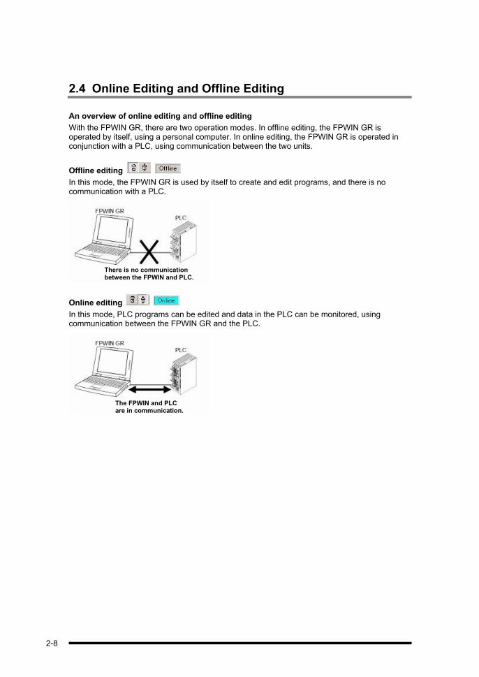
2.4 Online Editing and Offline Editing
An overview of online editing and offline editing
With the FPWIN GR, there are two operation modes. In offline editing, the FPWIN GR is operated by itself, using a personal computer. In online editing, the FPWIN GR is operated in conjunction with a PLC, using communication between the two units.
Offline editing
In this mode, the FPWIN GR is used by itself to create and edit programs, and there is no communication with a PLC.
There is no communication between the FPWIN and PLC.
Online editing
In this mode, PLC programs can be edited and data in the PLC can be monitored, using communication between the FPWIN GR and the PLC.
The FPWIN and PLC are in communication.
2-8

Switching modes
Switching between the online and offline editing modes is done by clicking with the mouse on “Online” on the menu bar, or using the [Alt] + [L] keys to switch between “Online Edit Mode” and “Offline Edit Mode” on the displayed menu.
The modes can also be switched without using menu operation, by the means described below.
- Keyboard operation + ( ) keys and + ( ) keys
- Tool bar operation
Clicking on and
Online editing
In online editing, as shown in the diagram below, programs in the PLC can be edited or monitored through communication between the FPWIN GR and the PLC.
With online editing, the contents of programs edited with the FPWIN GR, system register settings, and other data are reflected directly in the PLC.
Program in PLC
Reflected directly in program in PLC
Program conversion
Communication
2-9

KEY POINTS
There are two types of online editing.
Editing in the PROG. mode
With this method, programs in the PLC are rewritten with the PLC in the PROG.
mode. The program status bar displays the status via the
status indicators.
Editing in the RUN mode
With this method, programs in the PLC are rewritten with the PLC in the RUN
mode. The program status bar displays the status via the
status indicators.
PLC processing continues based on the edited program, so be sure that editing
is done properly.
The “Edit in RUN Mode” operation works differently depending on the type of
PLC being used.
PLCs in which the RUN status continues during program rewriting
- FP0, FP-X, FP SIGMA, FP-e, FP2, FP2SH, FP3, FP-C, FP10SH
PLCs in which the system switches to PROG. mode while the program is
rewritten, and then back to RUN mode after rewriting is finished
- FP1, FP-M
2-10

Chapter 3
Creating and Editing Programs

3.1 Before Creating a Program
3.1.1 Booting the FPWIN GR and Selecting the Type of PLC
1. Boot the FPWIN GR and select “New” on the startup menu.
Boot the FPWIN GR, and when the startup menu is displayed, select “New”.
2. Select the type of PLC.
A dialog box indicating the selectable types is displayed on the screen. Select the type of PLC to be used, and click on the “OK” button.
3. The FPWIN GR boots.
The FPWIN GR boots in the new program creation mode. The user can go ahead and begin programming.
next page
3-2
3-3
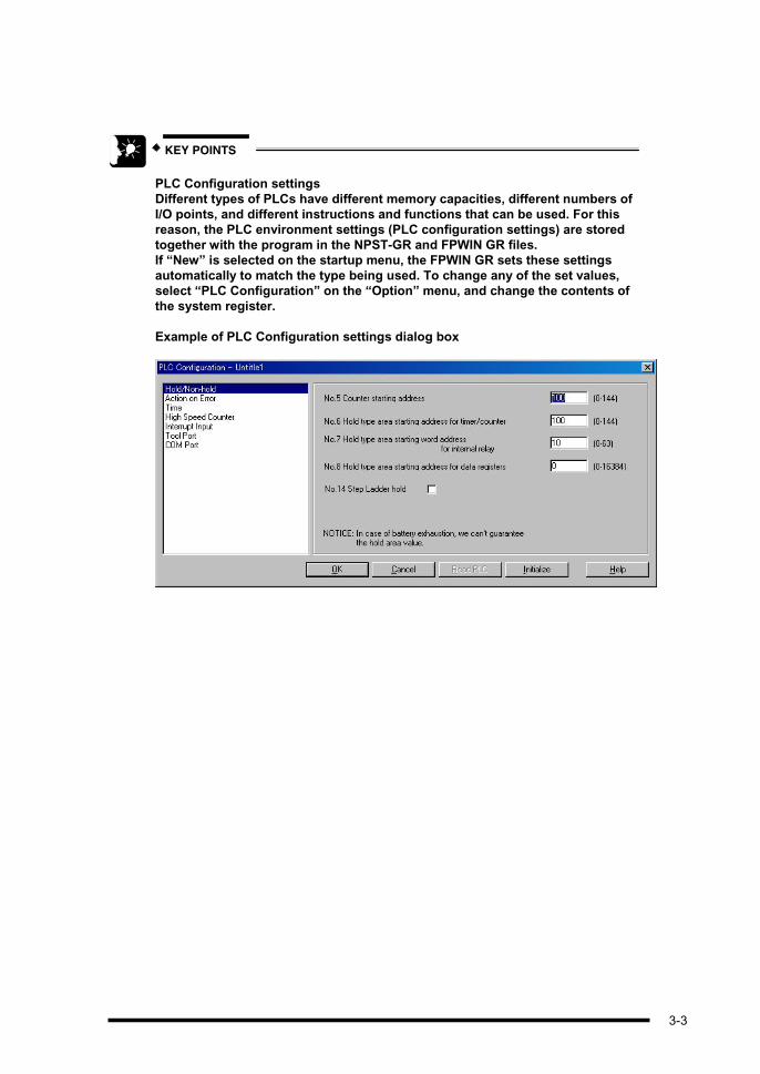
KEY POINTS
PLC Configuration settings Different types of PLCs have different memory capacities, different numbers of I/O points, and different instructions and functions that can be used. For this reason, the PLC environment settings (PLC configuration settings) are stored together with the program in the NPST-GR and FPWIN GR files. If “New” is selected on the startup menu, the FPWIN GR sets these settings automatically to match the type being used. To change any of the set values, select “PLC Configuration” on the “Option” menu, and change the contents of the system register.
Example of PLC Configuration settings dialog box
3.1.2 Clearing Programs
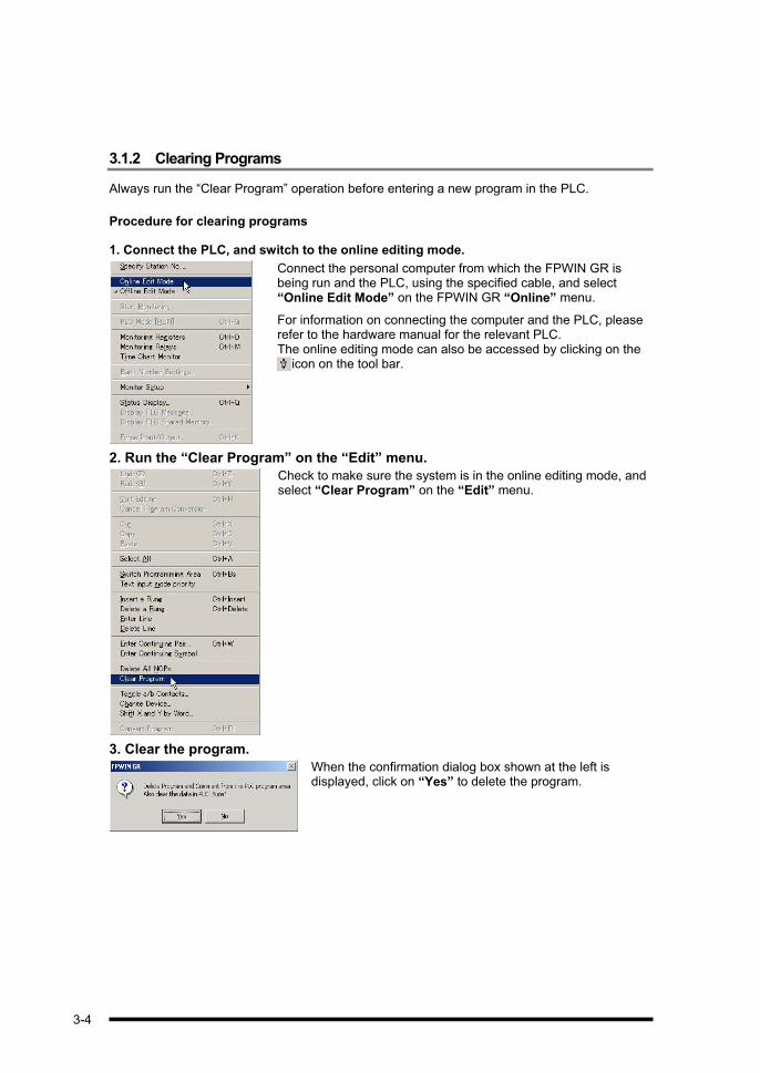
Always run the “Clear Program” operation before entering a new program in the PLC.
Procedure for clearing programs
1. Connect the PLC, and switch to the online editing mode.
Connect the personal computer from which the FPWIN GR is being run and the PLC, using the specified cable, and select “Online Edit Mode” on the FPWIN GR “Online” menu.
For information on connecting the computer and the PLC, please refer to the hardware manual for the relevant PLC. The online editing mode can also be accessed by clicking on the
icon on the tool bar.
2. Run the “Clear Program” on the “Edit” menu.
Check to make sure the system is in the online editing mode, and select “Clear Program” on the “Edit” menu.
3. Clear the program.
When the confirmation dialog box shown at the left is displayed, click on “Yes” to delete the program.
3-4

3.2 Creating Programs
3.2.1 Inputting a Sample Program
This section explains how to input the circuit shown below as a sample program.
The program is input by clicking with the mouse on the various instruction icons displayed on the function bar at the bottom of the screen. Programs can also be input using the function keys on the keyboard to which the various instructions are assigned.
1. Input relay X0.
First, input the relay X0 on the first line of the sample program. Move the cursor to the upper left corner of the program display field, and follow the procedure below to input the relay.
Procedure Input field display
1. Press ( ).
2. The function bar changes to a bit display. Press ( ).
3. After the type of relay has been input, click with the
mouse on on the ten-key bar, or press the
key on the keyboard.
4. Press the Return key to enter the instruction.
Screen display
2. Input the coil R0.
After the relay X0 has been input, input the coil R0, following the procedure below.
Procedure Input field display
1. Press ( ).
2. The function bar changes to a bit display. Press ( ).
3. After the type of coil has been input, press ( ).
4. Press the Return key to enter the instruction.
next page
3-5

Screen display
-The coil (OUT) instruction is automatically input at the right end, and the cursor moves to the beginning of the next line.
KEY POINTS
To draw a horizontal line, press the ( ) key. (To delete a horizontal
line, press the key.)
The ( ) key enters a vertical line to the left of the cursor position.
Pressing this key once more deletes the vertical line.
To configure the circuit, use the arrow keys ( , , , ) to move the cursor
and input the relays. Then press the ( ) key and the ( )
key to connect them.
The keys are convenient for direct device input.
When inputting a program, the devices listed below can be input directly
using the keys, in addition to being input from the function bar.
During basic instruction input
Device type Input using function bar Direct input using keys
X key key
Y key key
R key key
T + key key
C + key key
During input of high- level instructions, timer instruction, etc.
Device type Input using function bar Direct input using keys
K + key key
H + key key
DT key key
3-6

3.2.2 Checking the Sample Program
Program conversion (Compile)
When a program has been created or edited in the ladder symbol the area inside the program display field is highlighted in gray, as shown below. This indicates that program conversion needs to be carried out on the ladder in the highlighted area.
Programs can be converted by clicking with the mouse on on the function bar, or by pressing the + keys. Program creation or editing can be continued in the highlighted range, but if this is done, the program in its entirety should be converted after the programming or editing has been completed.
Running the program conversion (Compile) operation
-Using the menu ................Select “Convert Program” on the “Edit” menu.
-Keyboard operation..........Press + keys.
-Select items from the displayed menu by clicking the right button of the mouse.
KEY POINTS
Program conversion (Compile) can be carried out on up to 33 lines at a time.
With the FPWIN GR, it is not possible to edit 34 or more lines of the program at
one time.
3-7

3.2.3 Returning to Program Before Edit (Quit Editing)
If an error is made while programming, the “Return to program before edit” function can be run to go back to the version of the program that existed before the changes were made (right after the previous PG conversion (Compile) was run).
Returning to the version of the program conversion prior to changes
-Using the menu ............. Select “Quit Editing” on the “Edit” menu.
-Using the keyboard ....... Press + keys.
-Select items from the displayed menu by clicking the right button of the mouse.
3.2.4 Undo / Redo
If an error is made while programming, the “Undo” function can be run to go back to the version of the program that existed before the changes were made (right after the previous operation).
Returning to the version of the program prior to changes
-Using the menu ............. Select “Undo” on the “Edit” menu.
-Using the keyboard ....... Press + keys.
If you later decide you did not want to undo an action, Select “Redo” on the “Edit” menu or press + keys.
3-8

3.2.5 Inputting Instructions from the Function Bar
DF Leading edge differential
DF/ Trailing edge differential
Ladder notation Key operation procedure
( )1
( )
2 + ( )
( )3
( )
( )4
( )
5 + ( )
+ ( )
( )
③①
0
Y0X0
(DF )
②
⑥④
3
Y1X1
(DF/)
⑤
DF: The relay goes on for one scan only, when the leading edge of the signal is detected.
DF/: The relay goes on for one scan only, when the trailing edge of the signal is detected.
The key is used to switch between (DF) and
(DF/).
6
( )
3-9

SET Set
RST Reset
Ladder notation Key operation procedure
( )1
( )
+ ( )2
( )
( )3
( )
+ ( )4
( )
Y0
SET0
X0
Y0
RST4
X1
When the execution condition of the SET instruction goes on, the specified relay goes on, and remains on regardless of changes in the status of the execution condition.
When the execution condition of the RST instruction goes on, the specified relay goes off, and remains off regardless of changes in the status of the execution condition.
ST= 16- bit data comparison
Ladder notation Key operation procedure
( )
0
Y0K 50DT 0
A logical operation is initiated in response to the results of the comparison carried out on two operands.
1
( )
( )
( )
+ ( )
2 ( )
( )
3-10
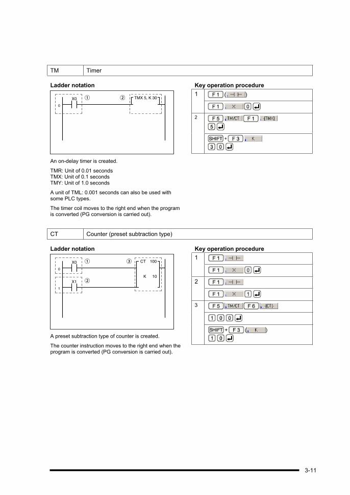
TM Timer
Ladder notation Key operation procedure
( )TMX 5, K 30②
①
0
X0
An on-delay timer is created.
TMR: Unit of 0.01 seconds TMX: Unit of 0.1 seconds TMY: Unit of 1.0 seconds
A unit of TML: 0.001 seconds can also be used with some PLC types.
The timer coil moves to the right end when the program is converted (PG conversion is carried out).
1
2
+
CT Counter (preset subtraction type)
Ladder notation Key operation procedure
1
2
3
+ ( )
CT 100③①0
X0
K 10②
1
X1
A preset subtraction type of counter is created.
The counter instruction moves to the right end when the program is converted (PG conversion is carried out).
3-11

3.2.6 Inputting Instructions not Found on the Function Bar
Inputting other instructions
Instructions that do not appear on the function bar can be input by pressing + ( ) keys or + ( ) keys to bring up the instruction entry dialog
box.
Instructions can then be selected from the dialog box.
Instruction entry dialog box
If + ( ) keys are pressed to input the instruction, the list shown at the left is displayed. Select the instruction to be input from the list and click on the “OK” button.
If the “Assign to Key” check box is on, as shown at the left, when a instruction is selected, the selected instruction will be assigned to a function key.
Instructions selected with the [ ] key will be assigned to the function key, and those selected with the [ ] key will be
assigned to the key.
3-12
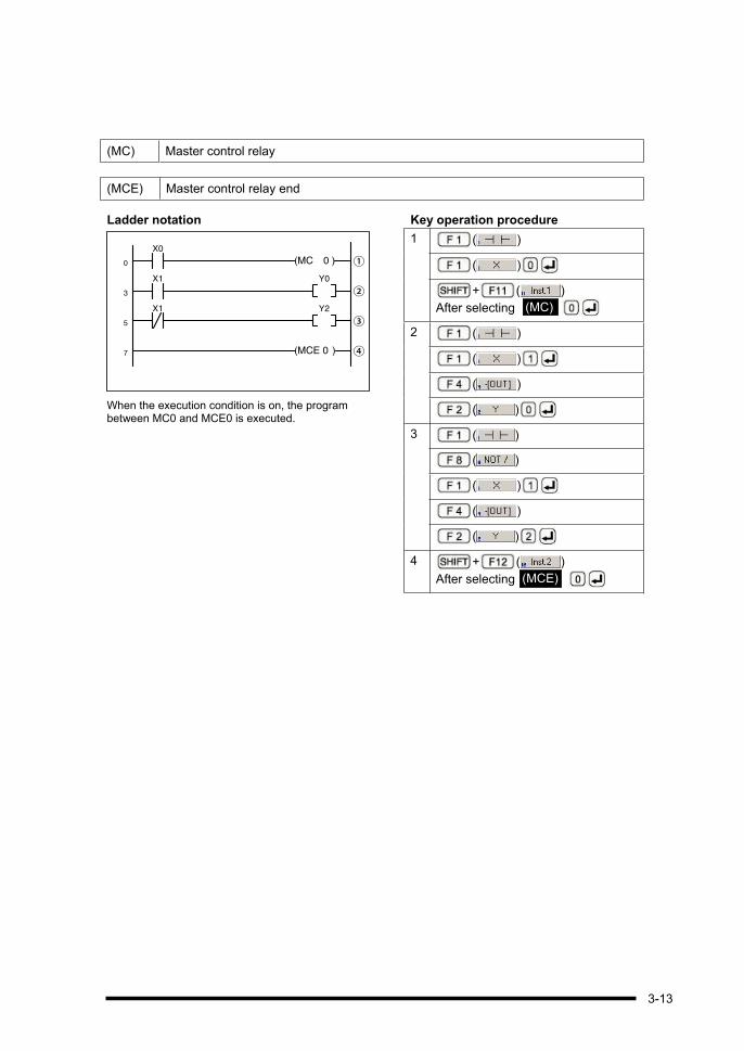
(MC) Master control relay
(MCE) Master control relay end
Ladder notation Key operation procedure
( )1
( )
+ ( )
After selecting ,
( )2
( )
( )
( )
( )3
( )
( )
( )
( )
4 + ( )
After selecting ,
①0
X0
②3
Y0X1
③5
Y2X1
④7
(MC 0
(MCE 0 )
)
When the execution condition is on, the program between MC0 and MCE0 is executed.
(MCE)
(MC)
3-13

3.2.7 Inputting High- level Instructions
How high- level instructions are input
High-level instructions are input by pressing the ( ) key. Check to make sure the cursor is positioned in the input field, and then input the number of the high- level instruction.
F0 16- bit data move
Ladder notation Key operation procedure
( )1
( )
( )2
( )
( )
②①
0 F0 MV , DT0 , DT10
X0
This transfers 16 bits of data from the specified source address to the destination address.
You can change the drawing start position of Function instruction by selection “Display Style Setup” on “File” menu from Ver.2.30.
KEY POINTS
Function instruction list When the ( ) key is
pressed to input a function
instruction (such as the high- level
instruction), the instruction can
also be input by selecting it from
the “Function Instruction List”
shown at the left, as well as by
inputting it using key operation.
next page
3-14

FPWIN GR Configuration dialog box To switch between using the keys to input a function instruction and selecting instructions from the “Function Instruction List”, select “FPWIN GR Configuration” on the “Option” menu, and then turn the check box labeled “Enter the function instruction from the list” displayed in the dialog box on or off.
3-15

3.2.8 Continuing Input
In the Ladder Symbol mode, if a ladder diagram is input that does not fit on one line, a line return can be input at the point at which the line returns. The input just before the bus line returns at the right end is called the continuing source, and the data at the beginning of the next line is called the continuing destination.
Continuing sourceContinuing destination
There are two types of continuing input: “Enter Continuing Pair” and “Enter Continuing Symbol”.
Enter continuing pair: The continuing source and continuing destination are specified as a pair.
Enter continuing symbol: The continuing source and the continuing destination are specified individually.
Operation procedure for continuing pair entry
With continuing source and continuing destination, the same number is assigned to both, and the user specifies from where to where the return is to be made. The operation can be interrupted by pressing the key.
1. Specify the continuing pair entry.
Continuing pair entry is selected on the “Edit” menu, by selecting “Enter Continuing Pair”.
The entry can also be specified in the following ways:
-Using the keyboard.............. Press the + keys.
-Using the tool bar ................ Click on .
-Click with the right button of the mouse to display a menu from which the entry can be selected.
2. Specify the continuing number.
When the continuing number dialog box is displayed, specify a number.
next page
3-16

3. Determine the position of continuing source (right end).
is displayed on the status bar. Either press the Return key
at the position of continuing source (right end), or click with the mouse.
4. Determine the position of continuing destination (left end).
When the position of continuing source (right end) has been determined, the message is displayed on the status bar. Either press the Return
key at the position of continuing destination (left end), or click with the mouse. The
continuing pair entry is set at the specified number.
Operation procedure for continuing symbol entry
If “Enter Continuing Symbol” has been specified, move the cursor and determine the position of continuing source (right end) or the position of continuing destination (left end). The operation can be interrupted by pressing the key.
1. Move the cursor to the position of continuing source (right end).
First, move the cursor to the position of continuing source (right end).
2. Specify the continuing symbol entry.
The continuing symbol entry is selected on the “Edit” menu, by selecting “Enter Continuing Symbol”.
There is another way to specify the entry, besides using the menu:
- Click with the right button of the mouse to display a menu from which the entry can be selected.
next page
3-17

3. Specify the continuing number.
The message is displayed on the status bar. Enter a two-digit continuing number. For example, to input No. 1, press keys.
4. Move the cursor to the position of continuing destination (left end).
Next, move the cursor to the position of continuing destination (left end).
5. Specify the continuing symbol entry.
The continuing symbol entry is selected on the “Edit” menu, by selecting “Enter Continuing Symbol”.
6. Specify the continuing number.
The message is displayed on the status bar. Enter a two-digit continuing number. For example, to input No. 1, press keys.
3-18

3.3 Correcting Programs
3.3.1 Deleting Instructions and Horizontal Lines
To delete instructions and horizontal lines, move the cursor to the position of the instruction or horizontal line to be deleted, and press the key.
Move cursor to line to be deleted
Press key.
The line is deleted, and the cursor moves.
Reference: To draw a horizontal line, press the ( ) key.
Deleting vertical lines
To delete a vertical line, move the cursor to the right of the vertical line to be deleted, and press the ( ) key.
Move cursor to right of vertical line to be deleted
Press ( ) key.
The vertical line is deleted.
Reference: Pressing the ( ) key once again inserts a vertical line at that position.
3.3.2 Adding Instructions
To add a relay on a horizontal line, it is not necessary to first delete the horizontal line; relays should be added on horizontal lines using the usual procedure. In the example shown below, the R4 relay is being added to the horizontal line.
Move cursor to position where relay is to be added
( )
( )
Relay is added
3-19

3.3.3 Changing Relay Numbers and Timer Set Value
Move the cursor to the position of the relay to be changed, and input the relay, using the usual procedure. In the example below, the X0 relay is changed to the X10 relay.
Move cursor to position where change is to be made
Press keys.
Relay number is changed
Changing timer set value
Move the cursor to the set value and change the value. In the example below, K10 is changed to K20.
Move cursor to position where change is to be made
Press keys.
Set value is changed
Reference: When the cursor reaches a position where the set value of timer can be changed, the current set value is displayed in the input field, and the function bar changes to a word display.
3.3.4 Inserting Instructions
Instructions can be inserted between instructions that have already been input.
To insert the instruction in front of the cursor, press the key to confirm the instruction, and to insert it after the cursor position, press + keys. In the example below, the R4 relay is inserted in front of X0.
Move cursor to insert position
( )
( )
R4 relay is inserted in front of X0
3.3.5 Inserting Rung
To insert the rung in an existing program, where additions or other changes will be made to the program, move the cursor to the position where the rung or rungs will be inserted, and then follow the procedure below.
3-20

Operation procedure
1. Move the cursor to the position where the rung will be inserted.
2. Insert the rung.
To insert the rung, select “Insert a Rung” on the “Edit” menu.
The insertion can also be specified in the following ways:
-Using the keyboard.........Press the + keys.
-Using the tool bar ...........Click on
- Click with the right button of the mouse to display a menu from which the insertion can be made.
3. The rung is inserted.
3.3.6 Deleting Rung
To delete a blank rung which is no longer needed, move the cursor to the position of the rung to be deleted, and follow the procedure below.
Operation procedure
-Using the menu: Select “Delete a Rung” on the “Edit” menu.
-Using the keyboard: Press + keys.
-Click with the right button of the mouse to display a menu from which the deletion can be made.
3-21

3.4 An Introduction to Other Functions
3.4.1 Changing Devices
An overview of the function for changing devices
This function is used to change types and numbers of relays in a program, and to change operand and numbers of instruction, and other parameters. Any relevant I/O comments can also be changed at the same time. (The remarks are not changed.)
Operation procedure
1. Select the “Change Device”.
To change a device, select “Change Device” on the “Edit” menu.
2. Specify the item of the device to be changed.
Specify the source device to the change and the range to which the change applies, as well as the destination device and the number from which the change is to start. Then click on the “Execute” button.
Devices which can be specified include the following:
X, Y, R, T, C, L, E, P, WX, WY, WR, WL, DT, SV, EV, FL, LD, JP, MC, MCE, LOOP, LBL, NSTP, SSTP, NSTP, NSTL, CSTP, CALL, FCAL, SUB, and SRWR.
3-22

Example of a device change
As shown at the left, [Source: R0 - RF] and [Destination: R10 - R1F] are specified, and then the “Execute” button is clicked. This changes the addresses of R0 - RF to R10 - R1F, as shown below.
Before the change
After the change
3-23
3.4.2 Shifting X and Y by Word
An overview of the XY word shift function
This function is used to shift relay numbers and coil numbers in the program in word units. If the configuration or specifications of input/output unit have been changed, executing “Shift X and Y Word” makes it easier to make changes in the program. Relevant I/O comments can also be changed at the same time. (The remarks are not changed.)
Operation procedure
1. Select the “Shift X and Y by Word”.
To select the shift X and Y by word, select “Shift X and Y Word” on the “Edit” menu.
2. Specify the item of device X and Y to be shifted.
Specify the area targeted for the shift, as well as the number following the shift, in word units. Then click on the “Execute” button.
3-24

Example of shifting X and Y by word
As shown at the left, [Area to Shift: 0 - 1] and [No. After Shift: 1 - 2] are specified, and then the “Execute” button is clicked. This shifts X0 - X1F to X10 - X2F, and Y0 - Y1F to Y10
- Y2F, as shown below.
Before the change
After the change
CAUTION
The XY word shift functions also shifts the input relays [X] and output relays [Y]
for the specified number range. To specify only the input relays [X] or only the
output relays [Y], use the “Change Device” function described on the page 3-24.
Example: If the area of 0 to 1 has been specified as the target for the shift, this
area will be targeted regardless of whether or not it is used in the program.
Input relays [X] X0 to XF
X10 to X1F
Output relays [Y] Y0 to YF
Y10 to Y1F
3-25
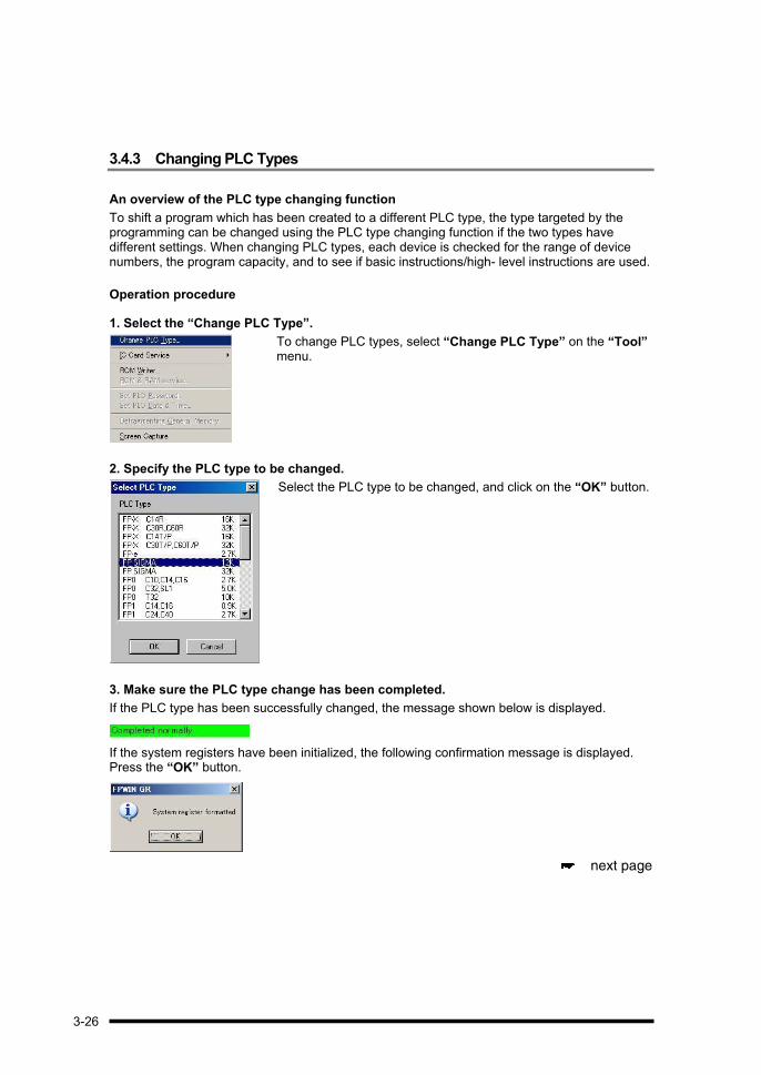
3.4.3 Changing PLC Types
An overview of the PLC type changing function
To shift a program which has been created to a different PLC type, the type targeted by the programming can be changed using the PLC type changing function if the two types have different settings. When changing PLC types, each device is checked for the range of device numbers, the program capacity, and to see if basic instructions/high- level instructions are used.
Operation procedure
1. Select the “Change PLC Type”.
To change PLC types, select “Change PLC Type” on the “Tool” menu.
2. Specify the PLC type to be changed.
Select the PLC type to be changed, and click on the “OK” button.
3. Make sure the PLC type change has been completed.
If the PLC type has been successfully changed, the message shown below is displayed.
If the system registers have been initialized, the following confirmation message is displayed. Press the “OK” button.
next page
3-26

CAUTION
If there are certain instructions that cannot be used on the selected PLC type, or
device numbers for areas that cannot be specified, a message like one of those
shown below is displayed.
Examples of type change error messages
The range of device numbers in the program prior to the type change must match
that of the type after the change. Make any necessary changes in the device
number ranges. (Any differences in the special data register DT9000 and DT90000
types will be converted automatically.)
The program capacities must also match. If necessary, delete part of the program
prior to the change.
If there are any instructions in the program prior to the change which cannot be
used after the change, edit them before the change is made.
For high- level instructions, “Configuration”
can be selected on the “Option” menu, and
the “Check the PLC Type of High- level
Instruction” check box in the displayed dialog
box turned on or off to specify whether or not
high- level instructions will be checked.
System registers are not initialized in the PLC type listed below, and should be
initialized by the user if necessary.
FP0 2.7 k <- -> FP0 5 k
FP1 0.9 k <- -> FP1 2.7 k <- -> FP1 5 k
FP3 10 k <- -> FP3 16 k
FP2 16 k <- -> FP2 32 k
FP2SH 60 k <- -> FP2SH 120 k
FP10SH 30 k <- -> FP10SH 60 k <- -> FP10SH 120 k
In any PLC types other than the above, the system registers are initialized.
3-27

3-28

Chapter 4
Transmitting Programs

4.1 Sending a Program to the PLC
An overview of program transmission
This function is used to send programs created and edited with the FPWIN GR to the PLC. To use this function, the personal computer and the tool port of the PLC should be connected with a cable.
Program transmissions such as downloading and uploading require communication between the FPWIN GR and the PLC. The FPWIN GR switches automatically to the online editing mode for such transmissions.
Downloading
Program being written
Operation procedure
1. Select the PLC to which the data is to be downloaded.
To send a program to the PLC, select “Download to PLC” on the “File” menu.
This can also be done in the following ways:
-Using the keyboard ...........Press the + keys.
-Using the tool bar ..............Click on
next page
4-2

2. Confirm the dialog box message.
When “Download to PLC” is selected, a dialog box like that at the left appears.
To continue the downloading process, click on the “Yes” button.
3. Confirm switching of the PLC operation mode.
If the PLC is in the RUN mode, a dialog box like that at the left appears.
To switch to the PROG. mode, click on the “Yes” button.
4. Display during downloading
The dialog box shown at the left is displayed while the program is being downloaded.
5. Confirm switching of the PLC operation mode.
If downloading is successfully completed, the dialog box shown at the left is displayed.
To switch to the RUN mode, click on the “Yes” button.
6. Downloading to the PLC is completed.
When the program has been downloaded to the PLC and the PLC has switched back to the RUN mode, the program status bar display changes to the following:
The program display switches to the monitoring status shown below.
4-3

CAUTION
Precautions when downloading a program that has comments If a program
containing comments is downloaded to a PLC with no area for writing comments,
the comments will not be sent to the PLC. Please be aware that, if the same
program is later returned (uploaded) to the FPWIN GR, the comments will have
disappeared.
If the other PLC has no comment writing area, a dialog box like that shown will be
displayed.
4-4
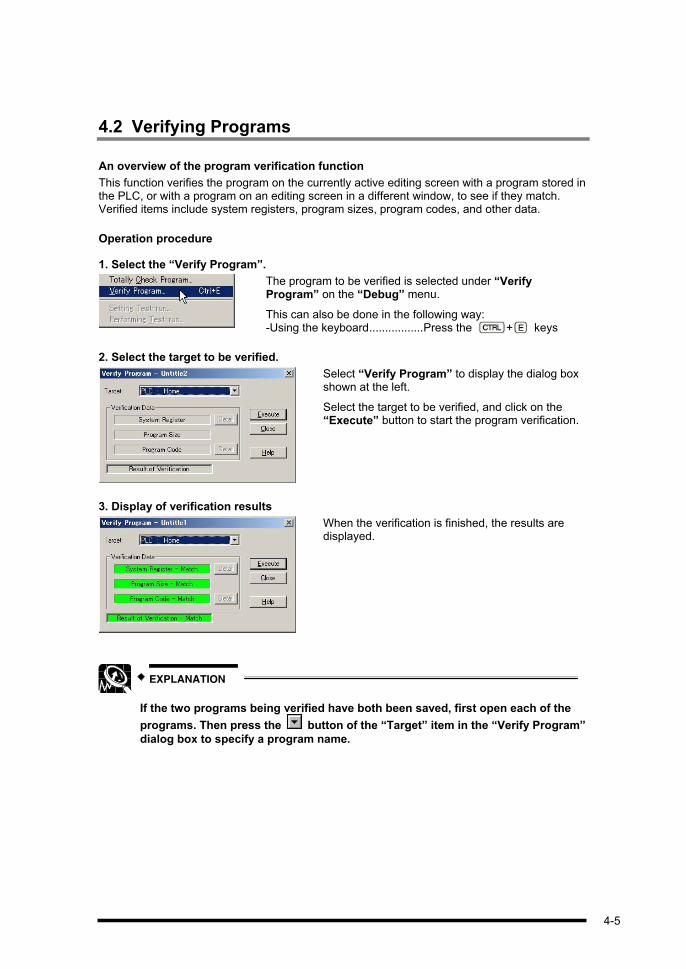
4.2 Verifying Programs
An overview of the program verification function
This function verifies the program on the currently active editing screen with a program stored in the PLC, or with a program on an editing screen in a different window, to see if they match. Verified items include system registers, program sizes, program codes, and other data.
Operation procedure
1. Select the “Verify Program”.
The program to be verified is selected under “Verify Program” on the “Debug” menu.
This can also be done in the following way: -Using the keyboard.................Press the + keys
2. Select the target to be verified.
Select “Verify Program” to display the dialog box shown at the left.
Select the target to be verified, and click on the “Execute” button to start the program verification.
3. Display of verification results
When the verification is finished, the results are displayed.
EXPLANATION
If the two programs being verified have both been saved, first open each of the
programs. Then press the button of the “Target” item in the “Verify Program”
dialog box to specify a program name.
4-5

4.3 Totally Check Program Function
An overview of the totally check program function
This function checks programs in the PLC and displays an error message if an error is detected. The totally check program function works only in the PROG. mode, when online with the PLC.
There is a possibility that the contents of the program displayed on the screen are different from those of the program stored in the PLC, so always run the “Verify Program” function before running a totally check program function.
Operation procedure
1. Select the “Totally Check Program”.
Select the totally check program function by selecting “Totally Check Program” on the “Debug” menu.
2. Run the totally check program function.
When “Totally Check Program” is selected, a dialog box like that shown at the left appears.
Clicking on the “Execute” button starts the totally check.
3. The totally check results are displayed.
If an error or errors exist, the number of errors, addresses and error contents are displayed.
Selecting (highlighting) the item to be searched and clicking on the “Jump” button jumps the cursor on the edit screen to the error address.
Selecting (highlighting) the item to be searched and clicking on the “Jump & Close” button, closes this dialog box and causes the edit screen cursor to jump to the error address.
4-6

4.4 Starting and Stopping Monitoring
An overview of the monitoring function
When the monitoring function is run, relays and data information can be confirmed in a ladder program in real time.
With the FPWIN GR, monitoring is initiated automatically when the FPWIN GR goes online, for example when a program is sent to the PLC. When the FPWIN GR switches back from the online to the offline mode, monitoring stops automatically. The settings for starting and stopping monitoring can be entered separately for each of the various windows.
Operation procedure
To start monitoring, select “Online” on the menu and then place a check mark by “Start Monitoring” in the displayed menu by clicking on it. Re-click to undo the checkmark and stop the monitor.
This can also be done in the following ways:
-Using the keyboard Press the + ( ) keys.
-Using the tool bar
Click on .
Note
From Ver.2.5, you can set the value by double-click the relay or register in a ladder view.
4-7

4.5 Monitoring Registers
An overview of the register monitoring function
Devices to be monitored in word units, such as data registers, can be registered, displayed as a table and monitored. Data can also be written and changed.
Operation procedure
1. Select the “Monitoring Registers”.
Register monitoring is selected by selecting “Monitoring Registers” on the “Online” menu.
This can also be done in the following way:
-Using the keyboard Press the + keys.
2. The registers monitoring window (screen) is displayed.
When “Monitoring Registers” is selected, the following window is displayed.
1 This displays the line number.
2 This displays the device code and device number.
3 This displays the monitored data values. Data can also be written and changed.
4 Base number (decimal, hexadecimal, binary, ASCII) being monitored are displayed, along with the number of words.
5 I/O comments pertaining to the various devices are displayed.
To change the column width, click the vertical separator and drag it. To save the column width, right - click in this dialog and select [Keep list width], or select [Keep list width] from the control menu. To initialize the column width, right - click in this dialog and select [Reset list width], or select [Reset list width] from the control menu.
4-8
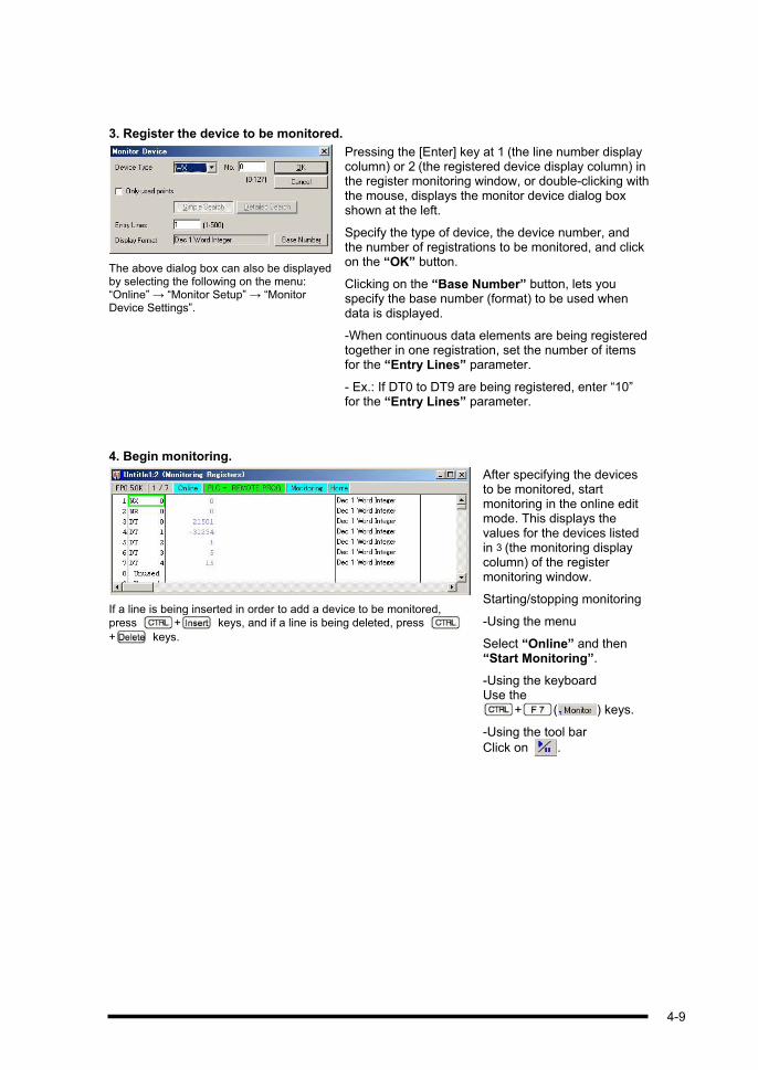
3. Register the device to be monitored.
The above dialog box can also be displayed by selecting the following on the menu: “Online” “Monitor Setup” “Monitor Device Settings”.
Pressing the [Enter] key at 1 (the line number display column) or 2 (the registered device display column) in the register monitoring window, or double-clicking with the mouse, displays the monitor device dialog box shown at the left.
Specify the type of device, the device number, and the number of registrations to be monitored, and click on the “OK” button.
Clicking on the “Base Number” button, lets you specify the base number (format) to be used when data is displayed.
-When continuous data elements are being registered together in one registration, set the number of items for the “Entry Lines” parameter.
- Ex.: If DT0 to DT9 are being registered, enter “10” for the “Entry Lines” parameter.
4. Begin monitoring.
If a line is being inserted in order to add a device to be monitored,
press + keys, and if a line is being deleted, press
+ keys.
After specifying the devices to be monitored, start monitoring in the online edit mode. This displays the values for the devices listed in 3 (the monitoring display column) of the register monitoring window.
Starting/stopping monitoring
-Using the menu
Select “Online” and then “Start Monitoring”.
-Using the keyboard Use the
+ ( ) keys.
-Using the tool bar
Click on .
4-9

KEY POINTS
Change the displayed radix.
The above dialog box can also be displayed using the following menu operations: “Online” “Monitor Setup” “Base Number Settings”. It can also be displayed by clicking on the “Base Number” button in the register monitoring window described earlier.
Either press the [Enter] key at 4 (the monitor base number display column) of the register monitoring window, or double- click with the mouse to display the monitor display format (base number) dialog box shown at the left. Specify the base number to which the display format (base number) is to be changed, and click on the “OK” button. To use real-number monitoring, select a Dec (Decimal) or 2 words.
Write the data.
The above dialog box can also be displayed using the following menu operations: “Online” “Monitor Setup” “Enter Value”.
When using the online monitoring function, either press the [Enter] key at 3 (the monitor display column) of the register monitoring window, or double- click with the mouse to display the data writing (Entering Value) dialog box shown at the left. Specify the value to be written, and click on the “OK” button.
From Ver.2.5, you can set the value by double-click the register in a ladder view.
Write a comment.
Either press the [Enter] key at 5(the comment display column) of the register monitoring window, or double- click with the mouse to display the I/O comment input (Enter I/O comment) dialog box shown at the left.
Specify the comment, and click on the “Entry” button.
+ keys can be used to move between the monitoring screen and the
program screen.
If the various windows are enlarged to the maximum size, the program screen will
be hidden behind the monitoring screen. To display the program screen, use
+ keys to switch the window, or select “The Horizontal” or “Tile
Vertical” on the “Window”.
4-10

4.6 Monitoring Relays
An overview of the relay monitoring function
With this function, relays and coils to be monitored can be registered and displayed in table form, so that the on/off statuses can be monitored. This function can also be used to turn relays on and off.
Operation procedure
1. Select the relay monitoring function.
The relay monitoring function is selected by selecting “Monitoring Relays” on the “Online” menu.
This can also be done in the following way:
-Using the keyboard Press the + keys.
2. The relay monitoring window (screen) is displayed.
When “Monitoring Relays” is selected, the following window is displayed.
1 This displays the line number.
2 This displays the device code and device number.
3 This displays the on/off statuses of the relays and coils being monitored. Relays can also be turned on and off.
4 I/O comments pertaining to the various devices are displayed.
next page
4-11

3. Register the relays to be monitored.
The menu operation selections “Online” “Monitor Setup” “Monitor Device Settings” can be used to display the above dialog box.
Pressing the [Enter] key at 1 (the line number display column) or 2 (the registered device display column) in the relay monitoring window, or double- clicking with the mouse, displays the monitor device dialog box shown at the left.
Specify the type of relay to be monitored, the number, and the number of registrations (entry lines), and click on the “OK” button.
When continuous data elements are being registered together in one registration, set the number of items for the “Entry Lines” parameter.
- Ex.: If X0 to XF are being registered, enter
“16” for the “Entry Lines” parameter.
4. Begin monitoring.
If a line is being inserted in order to add a device
to be monitored, press + keys, and if
a line is being deleted, press + keys.
When a relay or coil is turned on, the 3 (monitoring display column) section for that relay or coil is highlighted.
After specifying (highlighting) the devices to be monitored, start monitoring in the online edit mode. The on/off statuses of the relays and coils are displayed in 3 (the monitoring display column) of the relay monitoring window.
Starting/stopping monitoring
-Using the menu Select “Online” and then “Start Monitoring”.
-Using the keyboard Use the + ( ) keys.
-Using the tool bar Click on .
4-12

KEY POINTS
Write the data.
The above dialog box can also be displayed using the following menu operations: “Online” “Monitor Setup” “EnterValue”.
When using the online monitoring function, either press the [Enter] key at 4 (the monitor display column) of the relay monitoring window, or double- click with the mouse to display the data writing (Enter Value) dialog box shown at the left.
Set the value you wish to write and click the “OK” button.
From Ver.2.5, you can set the value by double-click the relay in a ladder view.
Write a comment.
Either press the [Enter] key at 5 (the comment display column) of the relay monitoring window, or double-click with the mouse to display the I/O comment input (Enter I/O comment) dialog box shown at the left.
Specify the comment, and click on the “Entry” button.
+ keys can be used to move between the monitoring screen and the
program screen.
If the various windows are enlarged to the maximum size, the program screen will
be hidden behind the monitoring screen. To display the program screen, use
+ keys to switch the window, or select “Sort and Display” on the
“Window”.
4-13

4.7 Forced Input and Output
An overview of the forced input/output function
The forced input/output function is used to forcibly turn relays and coils specified in a program on and off, regardless of the program itself. It is used for wiring of external input/output circuits, checks, simple manual operation, and other operations and adjustments.
Example of screen during forced input/output
If there are relays and/or coils that are being turned on and off forcibly, a display such as appears on the program status bar, and the relays and coils for which forced
input/output is being used are indicated as such by a special color on the ladder diagram (the default color is red).
When the PLC mode is switched from RUN to PROG., or from PROG. to RUN, all forced input/output in the PLC main unit is canceled.
From Ver.2.5, you can execute [Force Input/Output] function by [Ctrl] +
double-click the relay or coil in a ladder view.
Operation procedure
1. Select the forced input/output.
Forced input/output is selected by selecting “Force Input / Output” on the “Online” menu.
This can also be done in the following way:
-Using the keyboard Press the + keys.
4-14

2. The forced input/output dialog box is displayed.
Selecting “Force Input / Output” displays the dialog box shown at the left.
To register relays and coils targeted for forced input/output, click on the “Enter Device” button.
3. Register the device targeted for forced input/output.
Specify the type of device targeted, the number, and the number of registrations (Enter Lines), and click on the “OK” button.
If two or more registrations are specified, the numbers are registered automatically in sequential order.
4. Execute the forced input/output function.
Forced input/output can be specified for up to 16 points.
After selecting the device targeted for forced input/output, click on the “ON(1)” button.
This turns the selected device on forcibly, regardless of the program contents. Clicking on the “OFF (2)” button turns the selected device off.
Clicking on the “FREE (3)” buttonreturns operation to that specified by the program.
5. Cancel the forced input/output.
To cancel the forced input/output function, click on the “Release” button.
Forced input/output of the registered device is canceled, and a message reading “All points were cancelled” is displayed at the bottom of the dialog box.
4-15

KEY POINTS
An explanation of the forced input/output dialog box
This dialog box displays relays registered on the list, the status of the forced
input/output for each relay, and I/O comments.
Explanation of buttons
: Input/output is turned on forcibly for the selected relay, regardless of
the program.
: Input/output is turned off forcibly for the selected relay, regardless of
the program.
: This specifies that operation be executed as specified by the program
contents for the selected relay. If the PLC is in the PROG. mode,
however, or if a relay was forcibly turned on or off without the on/off
status being changed in the program, the status initiated by the
forced input/output will be maintained.
: This cancels all registered relays. If only the Cancel function is used,
however, if the PLC is in the PROG. mode, or if a relay was forcibly
turned on without the on/off status being changed in the program, the
status initiated by the forced input/output (the on status) is
maintained in some cases, so that the relay does not go off. To turn
the relay off, a forcible off should be executed for that relay, and then
the relay should be canceled.
: This deletes the currently selected (highlighted) relay from the
registration.
4-16

EXPLANATION
Multiple devices can be turned on and off at the same time by pressing the
+ keys to select the devices, or by pressing the key and
clicking on each device.
Space
CAUTION
The forced input/output function is extremely hazardous. Make sure sufficient
attention is given to the status of peripheral devices and equipment before
executing this function.
4-17
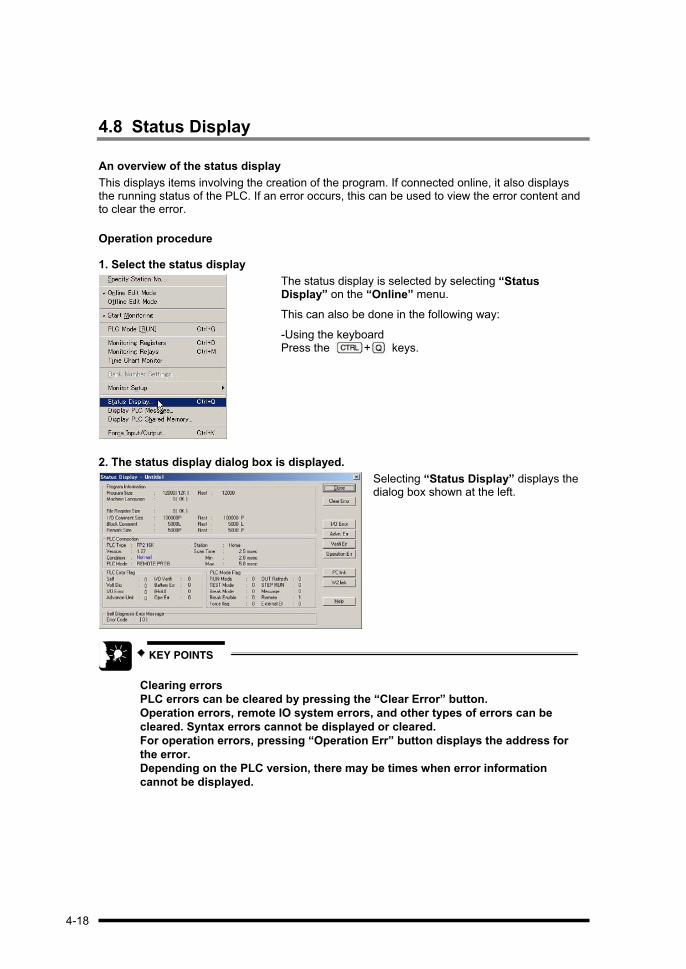
4.8 Status Display
An overview of the status display
This displays items involving the creation of the program. If connected online, it also displays the running status of the PLC. If an error occurs, this can be used to view the error content and to clear the error.
Operation procedure
1. Select the status display
The status display is selected by selecting “Status Display” on the “Online” menu.
This can also be done in the following way:
-Using the keyboard Press the + keys.
2. The status display dialog box is displayed.
Selecting “Status Display” displays the dialog box shown at the left.
KEY POINTS
Clearing errors
PLC errors can be cleared by pressing the “Clear Error” button.
Operation errors, remote IO system errors, and other types of errors can be
cleared. Syntax errors cannot be displayed or cleared.
For operation errors, pressing “Operation Err” button displays the address for
the error.
Depending on the PLC version, there may be times when error information
cannot be displayed.
4-18

Chapter 5
Saving a Program
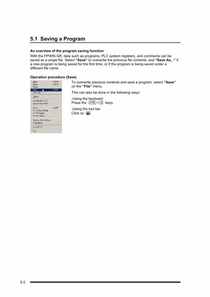
5.1 Saving a Program
An overview of the program saving function
With the FPWIN GR, data such as programs, PLC system registers, and comments can be saved as a single file. Select “Save” to overwrite the previous file contents, and “Save As...” ifa new program is being saved for the first time, or if the program is being saved under a different file name.
Operation procedure (Save)
To overwrite previous contents and save a program, select “Save” on the “File” menu.
This can also be done in the following ways:
-Using the keyboard Press the + keys.
-Using the tool bar
Click on .
5-2
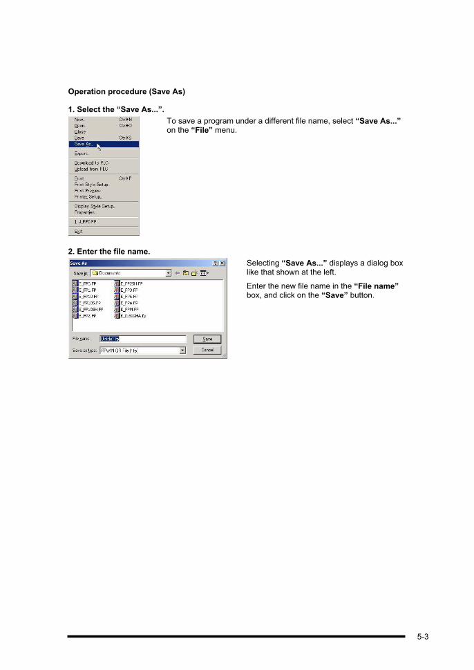
Operation procedure (Save As)
1. Select the “Save As...”.
To save a program under a different file name, select “Save As...” on the “File” menu.
2. Enter the file name.
Selecting “Save As...” displays a dialog box like that shown at the left.
Enter the new file name in the “File name” box, and click on the “Save” button.
5-3

EXPLANATION
Files created when saving
With the FPWIN GR, only one file is created when the data is saved, and the
expansion is “.fp”. The following contents are saved to this file:
Program itself
Contents of system register settings (including I/O unit assignments and
remote assignments)
Comments (I/O comments, remarks, block comment)
PLC type
Contents of relay monitoring and register monitoring registrations
Display style settings (Number of Ladder symbol, Drawing start position of
Function Instruction)
Printing style settings
Title and author
CAUTION
If comments disappear when files are saved
If the following procedure is carried out on a PLC that does not have a comment
memory, any comments that have been entered will be lost.
Be aware of this when overwriting the contents of previously saved files.
1. The program was created with comments included.
2. The program was downloaded to the PLC.
3. The program was saved and exited.
4. The program was uploaded from the PLC.
5. The file was overwritten and saved under the same file name.
When the program is loaded at step 4 , it does not include any comments, so
when it is overwritten and saved at step 5 , the comments are lost.
5-4

Chapter 6
Printing a Program

6-2
6.1 Printing a Program
6.1.1 Printing
This function is used to print programs, I/O lists, system registers, and other information.
Operation procedure
1. Select the printing function.
The printing function can be selected by selecting “Print...” on the “File” menu.
This can also be done in the following ways:
-Using the keyboard Press the + keys.
-Using the tool bar Click on .
2. The printing dialog box is displayed.
When “Print...” is selected, the dialog box shown at the left is displayed.
Check the printer to be used for printing, specify the printing range and number of copies to be printed, and click on “OK” button.
6.1.2 Setting the Printing Style
In the default settings, only ladder diagrams are specified as the contents to be printed. If necessary, use the “Print Style Setup” parameters to select other items to be printed.
Printout
Commercial printerFPWIN GR
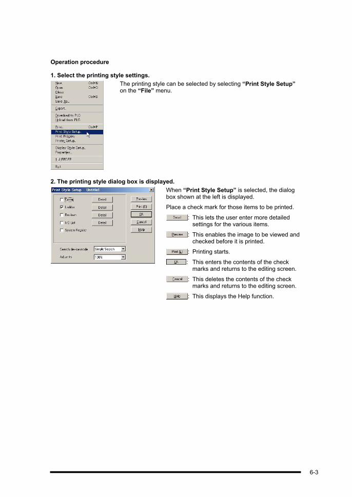
Operation procedure
1. Select the printing style settings.
The printing style can be selected by selecting “Print Style Setup” on the “File” menu.
2. The printing style dialog box is displayed.
When “Print Style Setup” is selected, the dialog box shown at the left is displayed.
Place a check mark for those items to be printed.
: This lets the user enter more detailed settings for the various items.
: This enables the image to be viewed and checked before it is printed.
: Printing starts.
: This enters the contents of the check marks and returns to the editing screen.
: This deletes the contents of the check marks and returns to the editing screen.
: This displays the Help function.
6-3

KEY POINTS
To print data that includes comments, press the “Detail” button for the ladder,
and place a check mark by the comment item.
EXPLANATION
To print a cover title, an item concerning the author, open “Properties” on the
“File” menu, and fill in the “Title” and “Author” entries.
6-4

KEY POINTS
Printing preview
To view and check the image before it is printed, select “Print Preview” on the
“File” menu, or double- click on “Preview” in the printing style settings dialog
box.
Printing preview screen
Explanation of buttons
: This initiates printing.
: If there are multiple pages, this jumps to the next page.
: This jumps to the previous page.
: This displays two pages at the same time.
: This enlarges the preview screen.
: This reduces the preview screen.
: This closes the printing preview screen and returns to the editing screen.
6-5

6-6

Chapter 7
Inputting Comments
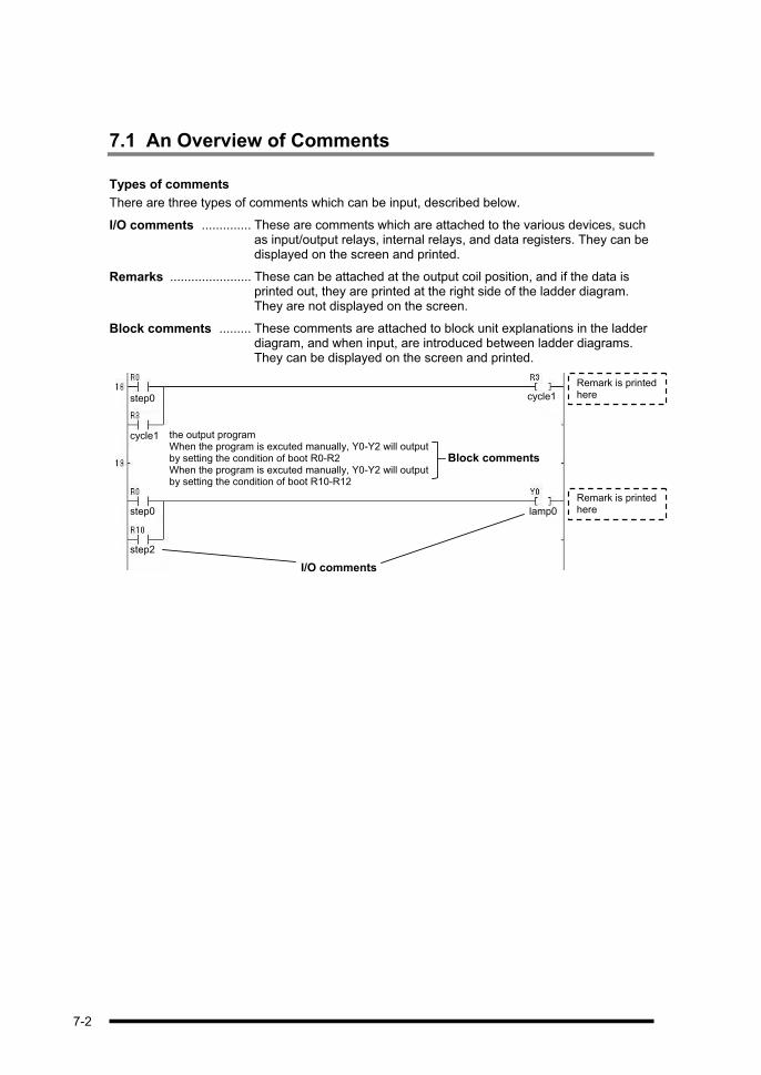
7.1 An Overview of Comments
Types of comments
There are three types of comments which can be input, described below.
I/O comments .............. These are comments which are attached to the various devices, such as input/output relays, internal relays, and data registers. They can be displayed on the screen and printed.
Remarks ....................... These can be attached at the output coil position, and if the data is printed out, they are printed at the right side of the ladder diagram. They are not displayed on the screen.
Block comments ......... These comments are attached to block unit explanations in the ladder diagram, and when input, are introduced between ladder diagrams. They can be displayed on the screen and printed.
Remark is printed herecycle1 step0
the output program When the program is excuted manually, Y0-Y2 will output by setting the condition of boot R0-R2 When the program is excuted manually, Y0-Y2 will output by setting the condition of boot R10-R12
cycle1
Block comments
Remark is printed herestep0 lamp0
I/O comments
step2
7-2

Switching the comment display on the screen
The following procedure is required in order to display the input comments on the screen.
1. Select the comment display function.
To display a comment on the screen, select “Display Comment” on the “View” menu.
This can also be done in the following ways:
-Using the keyboard Press the + keys.
-Using the tool bar
Click on .
2. The comments are displayed.
The ladder diagram is expanded vertically, and I/O comments are displayed on the screen. All block comments are displayed.
step2 input0 step1 step0
cycle1
step0
input1step0 step2 step1
step1
7-3
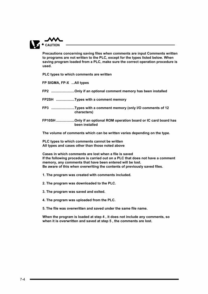
CAUTION
Precautions concerning saving files when comments are input Comments written
to programs are not written to the PLC, except for the types listed below. When
saving program loaded from a PLC, make sure the correct operation procedure is
used.
PLC types to which comments are written
FP SIGMA, FP-X ...All types
FP2 ........................Only if an optional comment memory has been installed
FP2SH ...................Types with a comment memory
FP3 ........................Types with a comment memory (only I/O comments of 12
characters)
FP10SH ...................Only if an optional ROM operation board or IC card board has
been installed
The volume of comments which can be written varies depending on the type.
PLC types to which comments cannot be written
All types and cases other than those noted above
Cases in which comments are lost when a file is saved
If the following procedure is carried out on a PLC that does not have a comment
memory, any comments that have been entered will be lost.
Be aware of this when overwriting the contents of previously saved files.
1. The program was created with comments included.
2. The program was downloaded to the PLC.
3. The program was saved and exited.
4. The program was uploaded from the PLC.
5. The file was overwritten and saved under the same file name.
When the program is loaded at step 4 , it does not include any comments, so
when it is overwritten and saved at step 5 , the comments are lost.
7-4

KEY POINTS
Loading comments
It is possible to read only comments from a file that has been saved.
Operation procedure
1. Upload the program from the PLC.
2. Select “Load I/O Comment” on the “Comment” menu.
3. Specify the program in which the comments have been saved, and load it.
I/O comment files by PLC type (special internal relays, special data registers)
Files to which I/O comments for special internal relays and special data registers have been input for the relevant PLC type are installed in the “Documents” folder. If “Load I/O Comment” is used to load the J_*.fp and E_*.fp files that matches the PLC type being used from this folder, it takes less time to input I/O comments for special internal relays and special data registers.
7-5

7.2 I/O Comments
An overview of I/O comments
These are comments that are attached to devices such as input and output relays, internal relays, and data registers. They can be displayed on the screen and printed. The edit I/O comment menu is convenient for inputting I/O comments.
Operation procedure
1. Select the I/O comment edit function.
The I/O comment edit function can be selected by selecting “Edit I/O Comment” on the “Comment” menu.
2. The I/O comment edit dialog box is displayed.
Selecting “Edit I/O Comment” displays a dialog box like that shown at the left.
Select “Device Type”, and align the cursor with the position at which the comment is to be input.
3. Prepare to input the comment.
Pressing the [Enter] key indents the area. The system waits for input to be entered.
4. Enter the comment.
Enter the text and press the [Enter] key. This completes the input procedure.
7-6
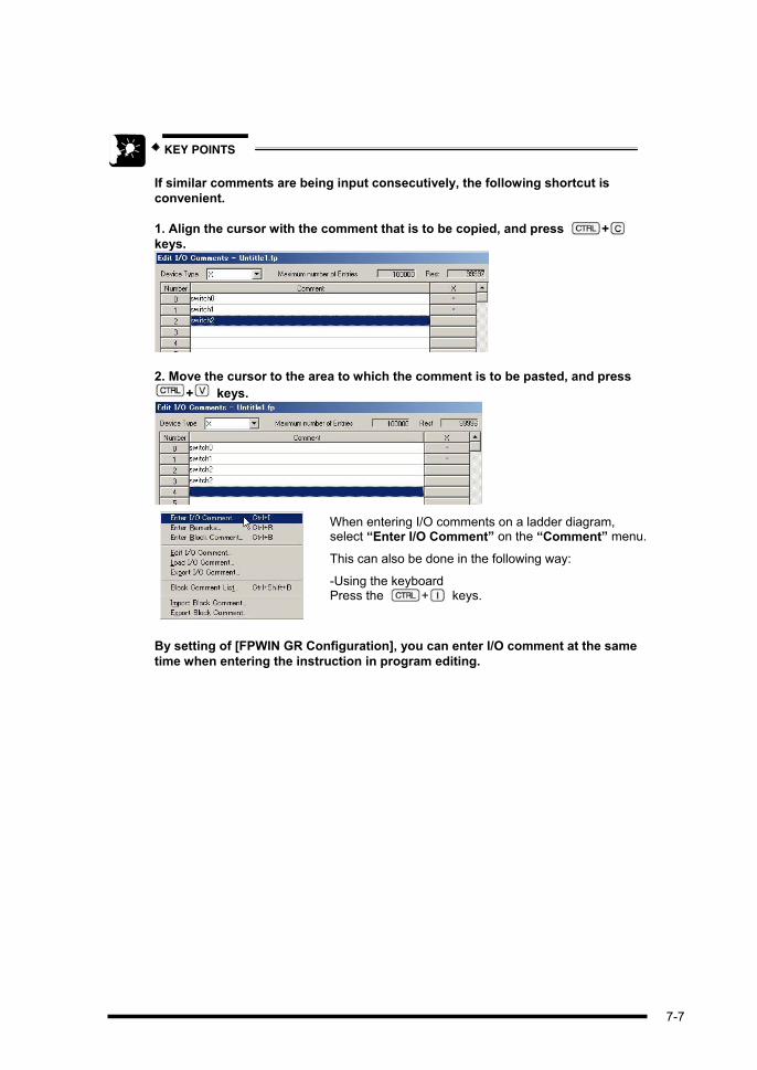
KEY POINTS
If similar comments are being input consecutively, the following shortcut is
convenient.
1. Align the cursor with the comment that is to be copied, and press +
keys.
2. Move the cursor to the area to which the comment is to be pasted, and press
+ keys.
When entering I/O comments on a ladder diagram, select “Enter I/O Comment” on the “Comment” menu.
This can also be done in the following way:
-Using the keyboard Press the + keys.
By setting of [FPWIN GR Configuration], you can enter I/O comment at the same
time when entering the instruction in program editing.
7-7
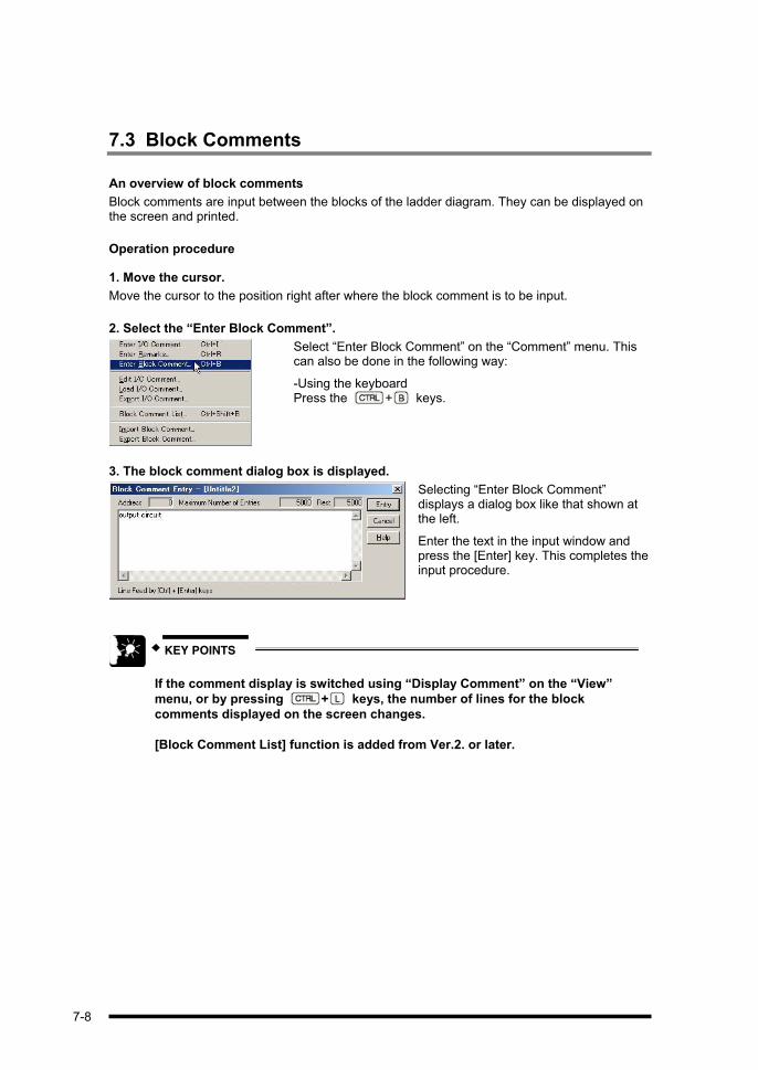
7.3 Block Comments
An overview of block comments
Block comments are input between the blocks of the ladder diagram. They can be displayed on the screen and printed.
Operation procedure
1. Move the cursor.
Move the cursor to the position right after where the block comment is to be input.
2. Select the “Enter Block Comment”.
Select “Enter Block Comment” on the “Comment” menu. This can also be done in the following way:
-Using the keyboard Press the + keys.
3. The block comment dialog box is displayed.
Selecting “Enter Block Comment” displays a dialog box like that shown at the left.
Enter the text in the input window and press the [Enter] key. This completes the input procedure.
KEY POINTS
If the comment display is switched using “Display Comment” on the “View”
menu, or by pressing + keys, the number of lines for the block
comments displayed on the screen changes.
[Block Comment List] function is added from Ver.2. or later.
7-8

7.4 Remarks
An overview of remarks
The remarks can be input only at the output coil position. When printed out, they are printed to the right of the bus line of the ladder diagram.
Operation procedure
1. Move the cursor.
Move the cursor to the output coil position where the remark is to be input.
2. Select the “Enter Remarks”.
Select “Enter Remarks” on the “Comment” menu. This can also be done in the following way:
-Using the keyboard Press the + keys.
3. The remark input dialog box is displayed.
Selecting “Enter Remarks” displays a dialog box like that shown at the left.
Enter the text in the input window and press the [Enter] key. This completes the input procedure.
KEY POINTS
The remarks that have been input can be confirmed using the comment display
bar.
You can also enter the remarks in Comment Display Bar.
7-9

7-10

Chapter 8
Searches
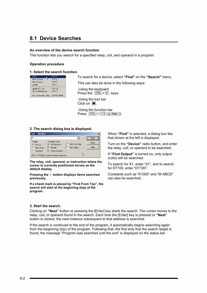
8.1 Device Searches
An overview of the device search function
This function lets you search for a specified relay, coil, and operand in a program.
Operation procedure
1. Select the search function.
To search for a device, select “Find” on the “Search” menu.
This can also be done in the following ways:
-Using the keyboard Press the + keys.
-Using the tool bar
Click on .
-Using the function bar Press + ( ).
2. The search dialog box is displayed.
The relay, coil, operand, or instruction where the cursor is currently positioned serves as the default display.
Pressing the button displays items searched previously.
If a check mark is placed by “Find From Top”, the search will start at the beginning (top) of the program.
When “Find” is selected, a dialog box like that shown at the left is displayed.
Turn on the “Device” radio button, and enter the relay, coil, or operand to be searched.
If “Find Output” is turned on, only output (coils) will be searched.
To search for X1, enter “X1”, and to search for DT100, enter “DT100”.
Constants such as “K1000” and “M ABCD” can also be searched.
3. Start the search.
Clicking on “Next” button or pressing the [Enter] key starts the search. The cursor moves to the relay, coil, or operand found in the search. Each time the [Enter] key is pressed or “Next” button is clicked, the next instance subsequent to that address is searched.
If the search is continued to the end of the program, it automatically begins searching again from the beginning (top) of the program. Following that, the first time that the search target is found, the message “Program was searched until the end” is displayed on the status bar.
8-2
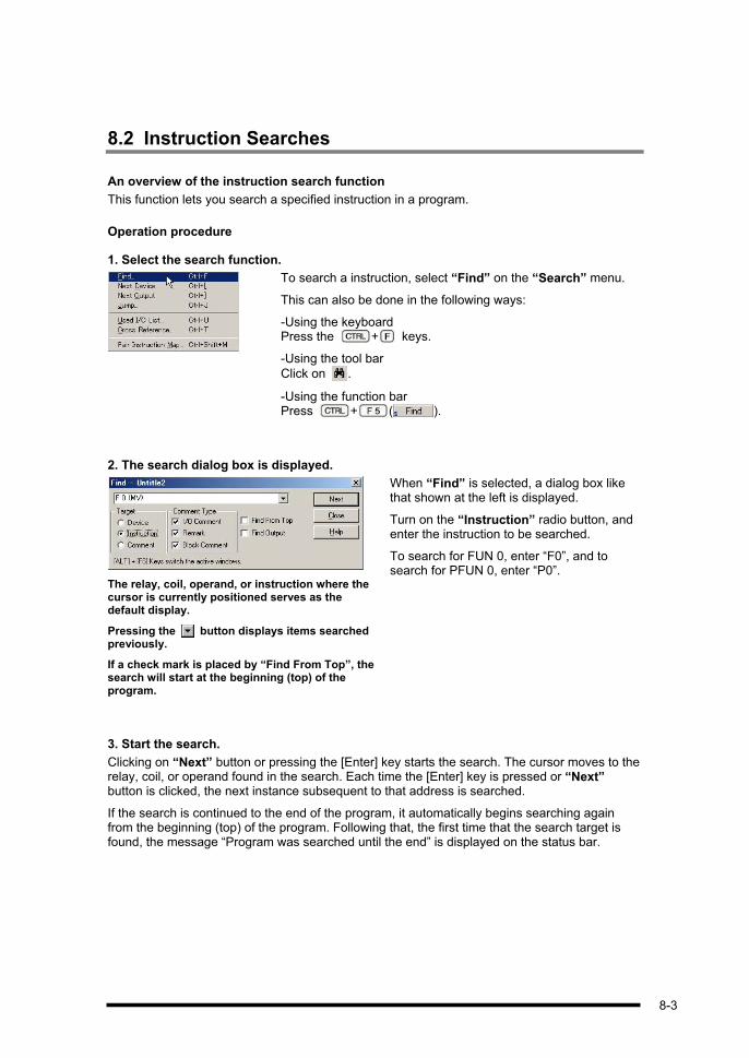
8.2 Instruction Searches
An overview of the instruction search function
This function lets you search a specified instruction in a program.
Operation procedure
1. Select the search function.
To search a instruction, select “Find” on the “Search” menu.
This can also be done in the following ways:
-Using the keyboard Press the + keys.
-Using the tool bar
Click on .
-Using the function bar Press + ( ).
2. The search dialog box is displayed.
The relay, coil, operand, or instruction where the cursor is currently positioned serves as the default display.
Pressing the button displays items searched previously.
If a check mark is placed by “Find From Top”, the search will start at the beginning (top) of the program.
When “Find” is selected, a dialog box like that shown at the left is displayed.
Turn on the “Instruction” radio button, and enter the instruction to be searched.
To search for FUN 0, enter “F0”, and to search for PFUN 0, enter “P0”.
3. Start the search.
Clicking on “Next” button or pressing the [Enter] key starts the search. The cursor moves to the relay, coil, or operand found in the search. Each time the [Enter] key is pressed or “Next” button is clicked, the next instance subsequent to that address is searched.
If the search is continued to the end of the program, it automatically begins searching again from the beginning (top) of the program. Following that, the first time that the search target is found, the message “Program was searched until the end” is displayed on the status bar.
8-3

8.3 Comment Searches
An overview of the comment search function
This function lets you search a specified comment (I/O comment, remarks, or block comment) in a program.
Operation procedure
1. Select the search function.
To search a comment, select “Find” on the “Search” menu.
This can also be done in the following ways:
-Using the keyboard Press the + keys.
-Using the tool bar
Click on .
-Using the function bar Press + ( ).
2. The search dialog box is displayed.
The relay, coil, operand, or instruction where the cursor is currently positioned serves as the default display.
Pressing the button displays items searched previously.
If a check mark is placed by “Find From Top”, the search will start at the beginning (top) of the program.
If a comment is searched with the comment display function turned off, the mode will automatically switch to the comment display mode.
When “Find” is selected, a dialog box like that shown at the left is displayed.
Turn on the “Comment” radio button, and, after selecting the type of comment, enter the comment to be searched.
If a check mark is entered for “Match Case”,the search distinguishes between upper- and lower-case characters.
-To search for SW0, enter “SW0”.
3. Start the search.
Clicking on “Next” button or pressing the [Enter] key starts the search. The cursor moves to the relay, coil, or operand found in the search. (If block comments are being searched, the cursor moves to the comment line.) Each time the [Enter] key is pressed or “Next” button is clicked, the next instance subsequent to that address is searched.
If the search is continued to the end of the program, it automatically begins searching again from the beginning (top) of the program. Following that, the first time that the search target is found, the message “Program was searched until the end” is displayed on the status bar.
8-4
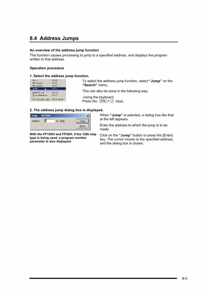
8.4 Address Jumps
An overview of the address jump function
This function causes processing to jump to a specified address, and displays the program written to that address.
Operation procedure
1. Select the address jump function.
To select the address jump function, select “Jump” on the “Search” menu.
This can also be done in the following way:
-Using the keyboard Press the + keys.
2. The address jump dialog box is displayed.
With the FP10SH and FP2SH, if the 120k step type is being used, a program number parameter is also displayed.
When “Jump” is selected, a dialog box like that at the left appears.
Enter the address to which the jump is to be made.
Click on the “Jump” button or press the [Enter] key. The cursor moves to the specified address, and the dialog box is closed.
8-5
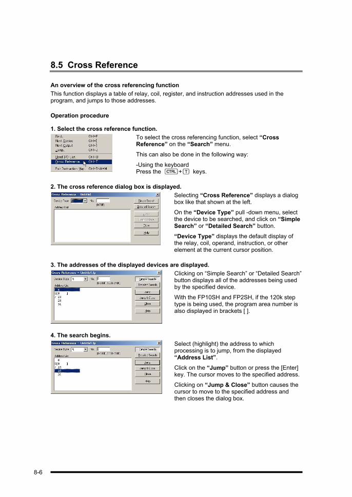
8.5 Cross Reference
An overview of the cross referencing function
This function displays a table of relay, coil, register, and instruction addresses used in the program, and jumps to those addresses.
Operation procedure
1. Select the cross reference function.
To select the cross referencing function, select “Cross Reference” on the “Search” menu.
This can also be done in the following way:
-Using the keyboard Press the + keys.
2. The cross reference dialog box is displayed.
Selecting “Cross Reference” displays a dialog box like that shown at the left.
On the “Device Type” pull -down menu, select the device to be searched, and click on “SimpleSearch” or “Detailed Search” button.
“Device Type” displays the default display of the relay, coil, operand, instruction, or other element at the current cursor position.
3. The addresses of the displayed devices are displayed.
Clicking on “Simple Search” or “Detailed Search” button displays all of the addresses being used by the specified device.
With the FP10SH and FP2SH, if the 120k step type is being used, the program area number is also displayed in brackets [ ].
4. The search begins.
Select (highlight) the address to which processing is to jump, from the displayed “Address List”.
Click on the “Jump” button or press the [Enter] key. The cursor moves to the specified address.
Clicking on “Jump & Close” button causes the cursor to move to the specified address and then closes the dialog box.
8-6
KEY POINTS
When making changes to a program in the ladder symbol mode, these addresses
cannot be displayed.
Items which can be searched include the following relays, coils, registers, and
instructions.
Relays ...........X, Y, R, L, T (TM), C (CT), E, P
Registers .......WX, WY, WR, WL, DT, SV, EV, FL, LD
Instructions ..MC, MCE, JP, LBL, LOOP, SSTP, NSTL, NSTP, CSTP, CALL, FCAL,
SUB, INT
8-7

8-8

Chapter 9
Menu Tables
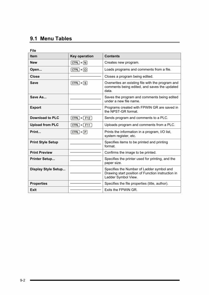
9.1 Menu Tables
File
Item Key operation Contents
New + Creates new program.
Open... + Loads programs and comments from a file.
Close Closes a program being edited.
Save + Overwrites an existing file with the program and comments being edited, and saves the updated data.
Save As... Saves the program and comments being edited under a new file name.
Export Programs created with FPWIN GR are saved in the NPST-GR format.
Download to PLC + Sends program and comments to a PLC.
Upload from PLC + Uploads program and comments from a PLC.
Print... + Prints the information in a program, I/O list, system register, etc.
Print Style Setup Specifies items to be printed and printing format.
Print Preview Confirms the image to be printed.
Printer Setup... Specifies the printer used for printing, and the paper size.
Display Style Setup... Specifies the Number of Ladder symbol and Drawing start position of Function instruction in Ladder Symbol View.
Properties Specifies the file properties (title, author).
Exit Exits the FPWIN GR.
9-2

Edit
Item Key operation Contents
Undo (Z) + The program changed with the instruction is restored to the previous status.
Redo (B) + The program restored by the Undo command is returned to the previous status.
Quit Editing + Returns to the previous program, before it was converted.
Cancel Program Conversion
Cancel the program conversion and return to the previous status.
Select Rect Mode + +
Switches the rectangle mode when you copy & paste program on ladder symbol view.
Cut + Deletes the specified portion of the program in line or block units, and stores it on the clipboard.
Copy + Copies the specified portion of the program in line or block units, and stores it on the clipboard.
Paste + Pastes the contents of the clipboard.
Select All + Selects the entire program.
Switch Programming Area
+ Switch between the two programming areas that FP10SH and FP2SH.
Text input mode priority
Text input mode priority
Insert a Rung + Inserts a rung in the program.
Delete a Rung + Deletes a rung from the program.
Enter Line Specifies two points and connects them with a line.
Delete Line Specifies two points and deletes the line between them.
Enter Continuing Pair + Specify continuing pair to connect the ladder diagram from current line to the line below.
Enter Continuing Symbol
Specify continuing number individually for connecting the ladder diagram.
Delete All NOPs Deletes all NOP instructions from a program.
Clear Program Deletes a program and any I/O comments in it.
Toggle a/b Contacts Specifies a device and contact number, and reverses the a and b contacts.
Change Device Specifies a range to be changed and changes the device type and number.
9-3

Item Key operation Contents
Shift X and Y by Word
Shifts relay numbers and coil numbers in word units.
Convert Program + Compiles a program created in ladder symbol, which is being edited.
Wizard
Item Key operation Contents
Positioning auxiliary function
Enter parameters in the setting items for the PLC positioning instruction, so that the requested instruction will be automatically expanded.
PID instruction input assistance
Enter values in setting items for the PID instruction and the requested instruction will be automatically expanded.
FP-e Screen display instructionassistance
Enter setting items for the screen display instruction and the requested instruction will be automatically expanded.
Scaling instruction input assistance
Enter parameters in the setting items for the PLC scaling instruction, so that the requested instruction will be automatically expanded.
Search
Item Key operation Contents
Find + Finds a relay, coil, or operand in a program.
Next Device + The next address to be used by the specified device is searched.
Next Output + The next address to be used by the specified output coil is searched.
Jump + Jumps to a specified address.
Used I/O List + Displays a list of usage statuses for relays, coils, registers, and instructions.
Cross Reference + Displays a list of addresses used for relays, coils, registers, and instructions, and enables jumping to those addresses.
Pair instruction Map + + This function allows you to understand the flow of entire program easily by listing the pair instructions that determine the program flow such as MC-MCE, JP-LABEL, or CALL SUB-RET.
9-4

Comment
Item Key operation Contents
Enter I/O Comment + Enters comments for various devices such as I/O relays, internal relays, and data registers.
Enter Remarks + Enters output comments, which are printed to the right of the ladder.
Enter Block Comment
+ B Enters a comment between lines of a ladder program.
Edit I/O Comment Enables editing of I/O comments in list format.
Load I/O Comment Loads only I/O comments from a file.
Export I/O comment Save I/O comments in a test file(.txt) or CSV file (.csv).
Block Comments List + + This function lists the block comments in the program, and allows you to understand the process of the entire program easily.
Import Block Comment
Loads block comments saved in a text file (.txt) to the program being edited.
Export Block Comment
Saves block comments from the program being edited to a text file (.txt).
9-5

View
Item Key operation Contents
Ladder Symbol View (LDS)
Switches the screen to ladder symbol view mode.
Boolean Ladder View (BLD)
Switches the screen to boolean ladder view mode.
Boolean Non-ladder View (BNL)
Switches the screen to boolean non-ladder view mode.
Display Comment + Switches display of comments on screen on/off.
Zoom Settings Enlarges/reduces size of display in window.
Monitoring Type Changes display radix used to monitor data on edit screen.
View Settings... Change the instruction font, font size of comments, comment font, ladder symbol width, and number of lines of I/O comments in the window.
Color Changes display color in various parts of edit screen.
Toolbar Displays tool bar.
Function bar Displays function bar.
Function bar Style Selects function bar display style.
Entry Bar Displays entry bar.
Tenkey Bar Displays ten key bar.
Input Field Bar Displays input field bar.
Comment Display Bar Displays comment display bar.
9-6

Online
Item Key operation Contents
Specify Station No. Specifies the communication station number.
Online Edit Mode + Selects the Online Edit mode.
Offline Edit Mode + Selects the Offline Edit mode.
Start Monitoring + Starts/stops monitoring in Online Edit mode.
PLC Mode [RUN] + Changes the PLC operation mode.
Monitoring Registers + Monitors values stored in relays, coils, and registers.
Monitoring Relays + Monitors on/off statuses of relays and coils.
Time Chart Monitor The menu for the time chart monitor is displayed.
Bank Number Settings
Switches bank of index register and file register to be monitored.
Monitor Setup Specifies data or relay monitoring.
Status Display + Displays the program environment and PLC status.
Display PLC Message Displays messages from the PLC.
Display PLC Shared Memory
Displays the contents of the shared memory in the high- level unit.
Force Input/Output + Forcibly turns relays and coils on and off.
Debug
Item Key operation Contents
Totally Check Program
Checks a program in the PLC.
Verify Program + Verifies the currently active program with one in the PLC or one in a different window, and checks them.
Verify Program Code + + Verifies the codes locating posterior to the cursor position in a program in a different window, and jumps to an error point.
Setting Test-run Enters settings for test operation.
Performing Test-run Tests a program to see if it runs as designed.
9-7

Tool
Item Key operation Contents
Change PLC Type Changes PLC type in program being edited.
IC Card Service Executes operations specified by data on an IC card.
ROM Writer Handles data communication with a ROM writer.
ROM & RAM Service Sends files between the ROM and RAM.
Internal Memory <=> Master Memory
Sends files between the Internal memory of FP-X and Master memory
Security Information Display security information of PLC.
Upload Settings Set disable or enable to upload the program from PLC.
Set PLC Password Sets the PLC password.
Set PLC Date & Time Sets the PLC date and time.
Defragmenting General Memory
General-purpose memory is re-organized.
Screen Capture Copies screen image data for a specified area to the Clipboard.
Option
Item Key operation Contents
PLC Configuration Sets PLC system registers.
Allocate I/O MAP Makes I/O assignments for the units installed in the slots.
Allocate Remote I/O MAP
Makes I/O assignments for units installed in slave slots in a remote I/O system.
MEWNET-W2 Settings Sets the network parameters of MEWNET-W2
MCU Settings Sets the parameters of MCU
Communication Settings
Sets conditions for communication between the PLC and computer.
FPWIN GR Configuration
Sets the operating environment for the FPWIN GR.
Customize Customize use of + Function key and
right click menu.
Keep Window Position
Saves each window position
Private Configuration This function allows you to save and call up your favorite tool configuration.
9-8
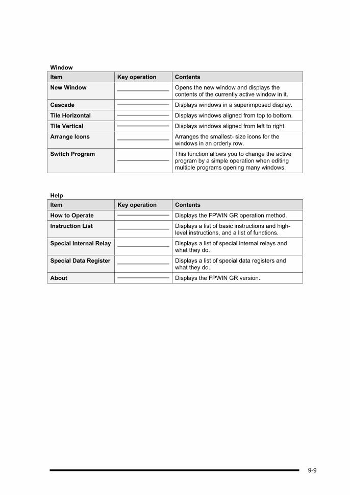
Window
Item Key operation Contents
New Window Opens the new window and displays the contents of the currently active window in it.
Cascade Displays windows in a superimposed display.
Tile Horizontal Displays windows aligned from top to bottom.
Tile Vertical Displays windows aligned from left to right.
Arrange Icons Arranges the smallest- size icons for the windows in an orderly row.
Switch Program This function allows you to change the active program by a simple operation when editing multiple programs opening many windows.
Help
Item Key operation Contents
How to Operate Displays the FPWIN GR operation method.
Instruction List Displays a list of basic instructions and high- level instructions, and a list of functions.
Special Internal Relay Displays a list of special internal relays and what they do.
Special Data Register Displays a list of special data registers and what they do.
About Displays the FPWIN GR version.
9-9

9.2 Function Bars
Default display
Default status
The actions of the function keys are as described below.
Key Display Description
Draws the symbol at the cursor position.
Draws the symbol at the cursor position.
Enters or deletes a vertical line to the left of the cursor position.
Enters the OUT instruction at the cursor line.
Enters a timer or counter at the cursor position.
Enters a Function instruction (such as the high- level instruction) at the cursor position.
Enters a horizontal line at the cursor position.
Inverts the operation results up to the cursor position.
Enters an index modifier at the cursor position.
Enters a Master Control instruction at the cursor position.
Enters a Master Control End instruction at the cursor position.
The instructions that can be input using or key are switched using + keys or + keys.
9-10

Status with the key pressed
When the key is pressed, the actions of the function keys are as described below.
Key Display Description
Enters the SET instruction at the cursor position.
Enters the RST instruction at the cursor position.
Enters a DF or DF/ instruction at the cursor position.
Enters an END instruction.
Enters a data comparison instruction.
Enters a PFun instruction (such as the high- level instruction) at the cursor position.
Enters a leading edge and trailing edge detection at the cursor position.
Switches the function bar display to a bit display.
Switches the function bar display to a word display.
Enters the instruction not found on the function bar.
Enters the instruction not found on the function bar.
Holding down the key switches between DF and DF/.
9-11

Status with the key pressed
When the key is pressed, the actions of the function keys are as described below.
Key Display Description
Carries out a PG conversion (compile).
Switches to the online editing mode.
Switches to the offline editing mode.
Closes the active window.
Searches for the instruction, comment, or other element.
Moves to the next window.
Starts/stops the monitoring function.
Displays the status.
Switches the PLC operation mode.
Loads a program from the PLC.
Writes a program to the PLC.
9-12

Bit display
When a relay or coil is input, the function bar changes to a bit display, as shown below.
Default status
The actions of function keys are as described below.
Key Display Description
Enters relay X in relation to the selected instruction.
Enters relay Y in relation to the selected instruction.
Enters relay R in relation to the selected instruction.
Enters relay L in relation to the selected instruction.
Enters relay P in relation to the selected instruction.
Enters a data comparison instruction.
Inverts the operation up to the cursor position.
Enters an index modifier at the cursor position.
Clears only the device number.
9-13

Status with the key pressed
When the key is pressed, the actions of the function keys are as described below.
Key Display Description
Enters relay T in relation to the selected instruction.
Enters relay C in relation to the selected instruction.
Enters relay E in relation to the selected instruction.
Enters the leading edge and trailing edge detection at the cursor position.
9-14

Word display
When the high- level instruction or similar instruction is input, the function bar changes to a bit display, as shown below.
Default status
The actions of the function keys are as described below.
Key Display Description
Enters WX at the cursor position.
Enters WY at the cursor position.
Enters WR at the cursor position.
Enters WL at the cursor position.
Enters a data register at the cursor position.
Enters a link data register at the cursor position.
Enters a file data register at the cursor position.
Enters an index modifier at the cursor position.
Clears only the device number.
9-15

Status with the key pressed
When the key is pressed, the actions of the function keys are as described below.
Key Display Description
Enters a timer set value at the cursor position.
Enters the timer elapsed value at the cursor position.
Enters a decimal constant at the cursor position.
Enters a hexadecimal constant at the cursor position.
Enters a character constant at the cursor position.
Enters a real number at the cursor position.
9-16
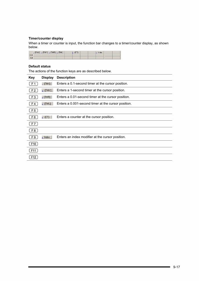
Timer/counter display
When a timer or counter is input, the function bar changes to a timer/counter display, as shown below.
Default status
The actions of the function keys are as described below.
Key Display Description
Enters a 0.1-second timer at the cursor position.
Enters a 1-second timer at the cursor position.
Enters a 0.01-second timer at the cursor position.
Enters a 0.001-second timer at the cursor position.
Enters a counter at the cursor position.
Enters an index modifier at the cursor position.
9-17

Comparison display
When a comparison instruction is input, the function bar changes to a comparison display, as shown below.
Default status
The actions of the function keys are as described below.
Key Display Description
Specifies a double word.
Specifies a floating point.
Enters the comparison operand =.
Enters the comparison operand >.
Enters the comparison operand <.
9-18

Index display
When an index register is input, the function bar changes to an index register display, as shown below.
Default status
The actions of the function keys are as described below.
Key Display Description
Enters index register IX or I0.
Enters index register IY or I1.
Enters index register I2.
Enters index register I3.
Enters index register I4.
Enters index register I5.
Enters index register I6.
Enters index register I7.
Enters index register I8.
9-19

Status with the key pressed
When the key is pressed, the actions of the function keys are as described below.
Key Display Description
Enters index register I9.
Enters index register IA.
Enters index register IB.
Enters index register IC.
Enters index register ID.
9-20

9.3 Tool Bar List
The functions of the various tool bar icons are shown below.
Create new file
Open file
Save file
Upload from PLC
Download to PLC
Select Rect Mode
Cut
Copy
Paste
Insert a rung
Enter continuing pair
Text input mode
Program conversion (compile)
Search
Comment display on/off
Keep window position
Switch to offline mode
Switch to online mode
Switch to PLC mode [RUN]
Run/stop monitoring function
Version display
9-21

9-22

Chapter 10
Precautions Concerning Usage
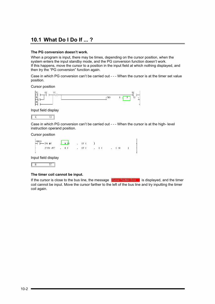
10.1 What Do I Do If ... ?
The PG conversion doesn’t work.
When a program is input, there may be times, depending on the cursor position, when the system enters the input standby mode, and the PG conversion function doesn’t work. If this happens, move the cursor to a position in the input field at which nothing displayed, and then try the “PG conversion” function again.
Case in which PG conversion can’t be carried out - - - When the cursor is at the timer set value position.
Cursor position
Input field display
Case in which PG conversion can’t be carried out - - - When the cursor is at the high- level instruction operand position.
Cursor position
Input field display
The timer coil cannot be input.
If the cursor is close to the bus line, the message is displayed, and the timer
coil cannot be input. Move the cursor farther to the left of the bus line and try inputting the timer coil again.
10-2

A vertical line cannot be deleted.
To delete a vertical line, move the cursor to the right of the target line, and press the ( ) key. Pressing the ( ) key once again inserts a vertical line.
Move the cursor to the right of the vertical line.
Press the ( ) key.
The vertical line disappears.
The Edit mode was entered by mistake.
If the key was pressed by mistake, the area targeted by the program change will be
displayed in gray, and the system will wait for a PG conversion to be carried out. If this happens, either press the + keys, or select “Quit Editing” on the “Edit” menu, and cancel the edit mode. The right button of the mouse can also be clicked to display the menu.
10-3
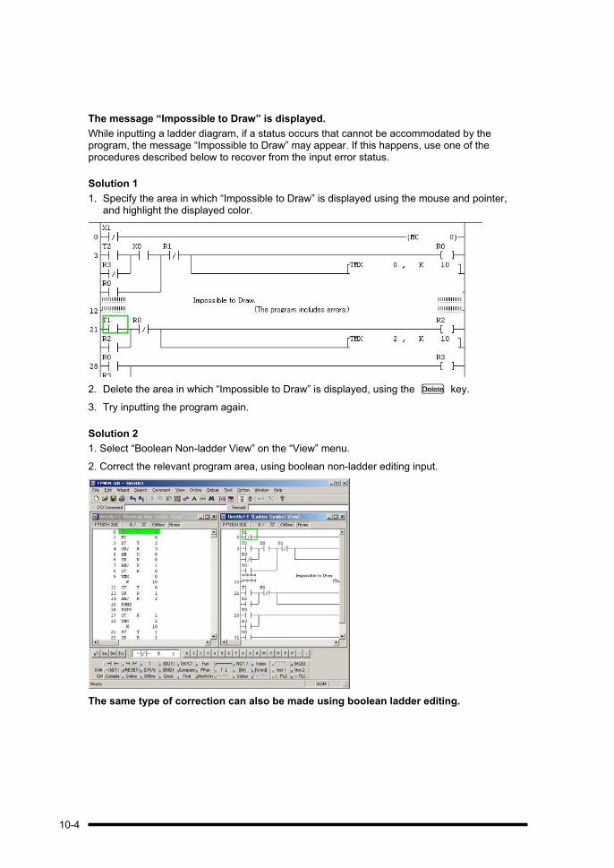
The message “Impossible to Draw” is displayed.
While inputting a ladder diagram, if a status occurs that cannot be accommodated by the program, the message “Impossible to Draw” may appear. If this happens, use one of the procedures described below to recover from the input error status.
Solution 1
1. Specify the area in which “Impossible to Draw” is displayed using the mouse and pointer, and highlight the displayed color.
2. Delete the area in which “Impossible to Draw” is displayed, using the key.
3. Try inputting the program again.
Solution 2
1. Select “Boolean Non-ladder View” on the “View” menu.
2. Correct the relevant program area, using boolean non-ladder editing input.
The same type of correction can also be made using boolean ladder editing.
10-4
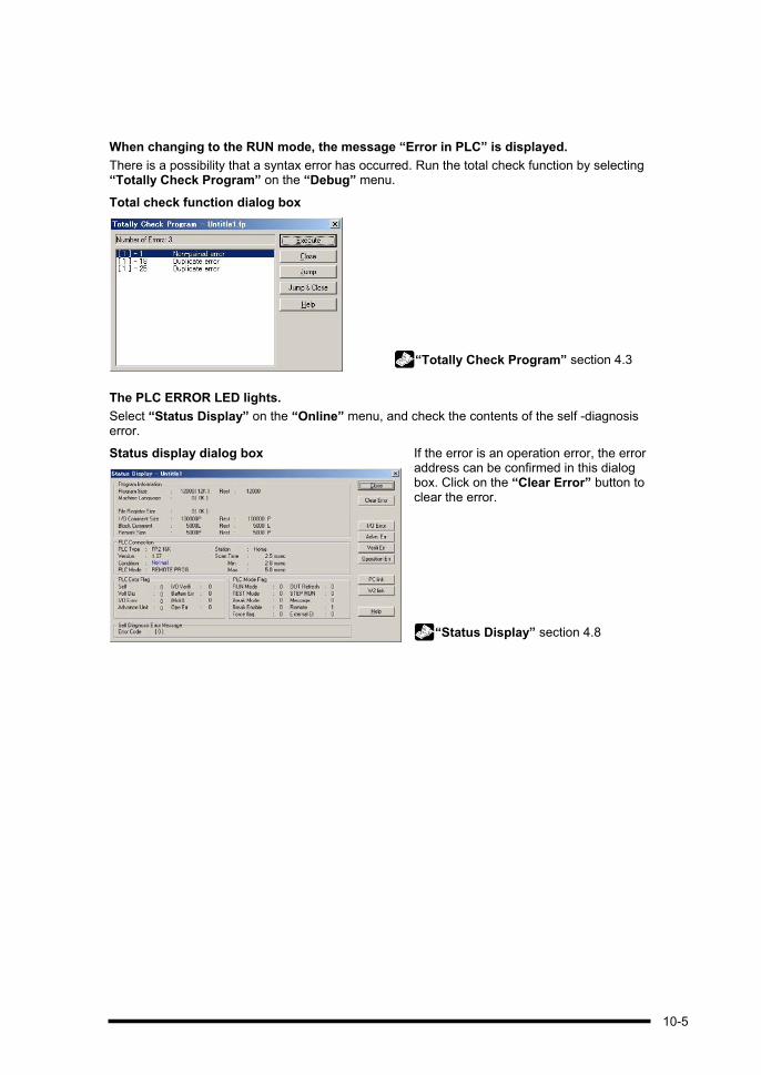
When changing to the RUN mode, the message “Error in PLC” is displayed.
There is a possibility that a syntax error has occurred. Run the total check function by selecting “Totally Check Program” on the “Debug” menu.
Total check function dialog box
“Totally Check Program” section 4.3
The PLC ERROR LED lights.
Select “Status Display” on the “Online” menu, and check the contents of the self -diagnosis error.
Status display dialog box If the error is an operation error, the error address can be confirmed in this dialog box. Click on the “Clear Error” button to clear the error.
“Status Display” section 4.8
10-5

10-6

Record of changes
Manual No. Date Description of Changes
ARCT1F308E/ ACG-M308E
Apr. 2000 First edition
ARCT1F308E-1/ ACG-M308E-1
Aug. 2000 2nd edition
ARCT1F332E/ ACG-M332E
Dec. 2002 3rd edition Additional Functions in Ver.2
ARCT1F332E-1/ ACG-M332E-1
Nov. 2003 4th edition Additional Functions in Ver.2.3
ARCT1F332E-2/ ACG-M332E-2
July. 2004 5th edition Additional Functions in Ver.2.4
ARCT1F332E-5/ ACG-M332E-5
Mar. 2005 6th edition Additional Functions in Ver.2.5
ARCT1F332E-6/ ACG-M332E-6
Sep. 2005 7th edition Additional Functions in Ver.2.6
ARCT1F332E-7/ ACG-M332E-7
Aug. 2006 8th edition Additional Functions in Ver.2.7
