this document was downloaded from the penspen integrity ... · specific pipeline, enabling the...
TRANSCRIPT

This document was downloaded from the Penspen Integrity Virtual Library
For further information, contact Penspen Integrity:
Penspen Integrity Units 7-8
St. Peter's Wharf Newcastle upon Tyne
NE6 1TZ United Kingdom
Telephone: +44 (0)191 238 2200
Fax: +44 (0)191 275 9786 Email: [email protected]
Website: www.penspenintegrity.com

International Conference on The Evaluation and Rehabilitation of Pipelines Prague, October 2008
© Page 1 of 27
A Proposal for the Development of an International Recommended
Practice in Pipeline Defect Assessment and Repair Selection
Roland Palmer-Jones, Susannah Turner, Phil Hopkins
Abstract:
Penspen developed the Pipeline Defect Assessment Manual (‘PDAM’) as a Joint Industry project for a group of 19 sponsors. This manual provides detailed guidance on the assessment of pipeline defects, and is considered to define ‘best practice’. The manual is detailed and is suitable for engineers with experience of pipeline engineering and defect assessment to use. Penspen has since developed a number of pipeline specific defect evaluation procedures for use by experienced field technicians. These procedures provide a bespoke interpretation of PDAM for a specific pipeline, enabling the rapid and reliable assessment of defects found in the pipeline. Penspen has also completed a number of pipeline emergency repair studies, aimed at ensuring that pipeline operators can identify severe defects, and complete an appropriate repair as quickly as possible. Based on our experience of developing these procedures we have identified the need for an international recommended practice or standard to help pipeline operators to safely assess defects they find in their pipelines and to select appropriate repairs.
This paper presents an outline of an international recommended practice for pipeline defect assessment and repair for discussion by the industry.

International Conference on The Evaluation and Rehabilitation of Pipelines Prague, October 2008
© Page 2 of 27
1 Introduction
Defects such as internal and external corrosion, dents, and gouges are regularly found in oil and gas pipelines. In the majority of cases these defects are minor and have no impact on the integrity and safety of the pipeline. But in some cases they can be significant and a repair is necessary. Consequently, a reliable way of identifying defects that are critical, and need repair is required. The twin requirements of security of supply, and operating efficiency, mean that repairs should not be carried out if they are not required; hence, any method of identifying and assessing critical defects must be accurate and not excessively conservative. Furthermore, to ensure long term integrity, an appropriate repair must be selected.
Penspen developed the Pipeline Defect Assessment Manual (‘PDAM’) as a Joint Industry project for a group of 19 sponsors[1]. This manual provides detailed guidance on the assessment of pipeline defects, and is considered to define ‘best practice’. The manual is detailed and is suitable for engineers with experience of pipeline engineering and defect assessment. Penspen has since developed a number of pipeline-specific defect evaluation procedures for use by experienced field technicians. These procedures provide a bespoke interpretation of PDAM for a specific pipeline, enabling the rapid and reliable assessment of defects found in the pipeline. Penspen has also completed a number of pipeline emergency repair studies, aimed at ensuring that pipeline operators can identify severe defects, and complete an appropriate repair as quickly as possible. Based on our experience of developing these procedures we have identified the need for an international recommended practice or standard to help pipeline operators to safely assess defects they find in their pipelines and to select appropriate repairs.
This paper presents an outline version of an international recommended practice for pipeline defect assessment and repair for discussion by the industry. The outline version covers the entire process that is common to all defect types, and uses corrosion defects to illustrate the process.
2 Overview
This draft recommended practice details the decision process to be followed and the actions to be taken on discovery of a pipeline defect. The objective of the process is to categorise defects as ‘Superficial’, ‘Moderate’, or ‘Severe’, and define actions that should be taken depending on the categorisation.
It is proposed that the overall defect assessment process follows a series of tasks as summarised in Figure 1.

International Conference on The Evaluation and Rehabilitation of Pipelines Prague, October 2008
© Page 3 of 27
The expected outcomes for different defect types is summarised in Table 1 to allow quick identification of ‘Severe’ features. It is important that the tasks in the recommended practice are followed to ensure the assessment is safe and appropriate.
Figure 1 Defect Assessment Tasks
Defect Reported
TASK 1: Preliminary Actions and Data Recording
TASK 2: Assess requirement for immediate pressure reduction or pressure reduction during inspection
TASK 3: Assess requirement for site investigation
TASK 4: Site Investigation Defect Measurement and Data Recording
TASK 5: Defect Assessment Procedures and Categorisation Charts
TASK 6: Actions

International Conference on The Evaluation and Rehabilitation of Pipelines Prague, October 2008
© Page 4 of 27
Defect Type Expected Categorisation Expected Actions
• Gouges on welds
• Kinked dents
• Smooth dents and gouge
SEVERE
IMMEDIATE RESPONSE REQUIRED:
• Pressure reductions
• Repair or further action within 30 days
• Gouges
• Cracking Subject to assessment
RESPONSE REQUIRED:
• Pressure reductions required
• Dressing or other repair required for all defects
• Further actions and timescales subject to assessment
• Corrosion
• Plain dents
• Smooth dents on welds
• Weld defects
• Manufacturing defects
Subject to assessment
RESPONSE MAY BE REQUIRED:
• Actions and timescales subject to assessment
Table 1 Expected actions for different types of defect
3 TASK 1: Preliminary Action
A defect may be reported by an inline inspection or during a visual examination. Alternatively, damage may be suspected if routine maintenance or inspection reveals anomalous CP readings, coating anomalies, or indications of third party activity in the vicinity of the pipeline. Damage to the pipeline may also be suspected after reported mechanical damage incidents. An existing, known defect may also require investigation as part of an ongoing monitoring programme.
On receiving a defect report, an initial assessment of the available information should be performed to:
• Identify the defect type (see 3.1).
International Conference on The Evaluation and Rehabilitation of Pipelines Prague, October 2008
© Page 5 of 27
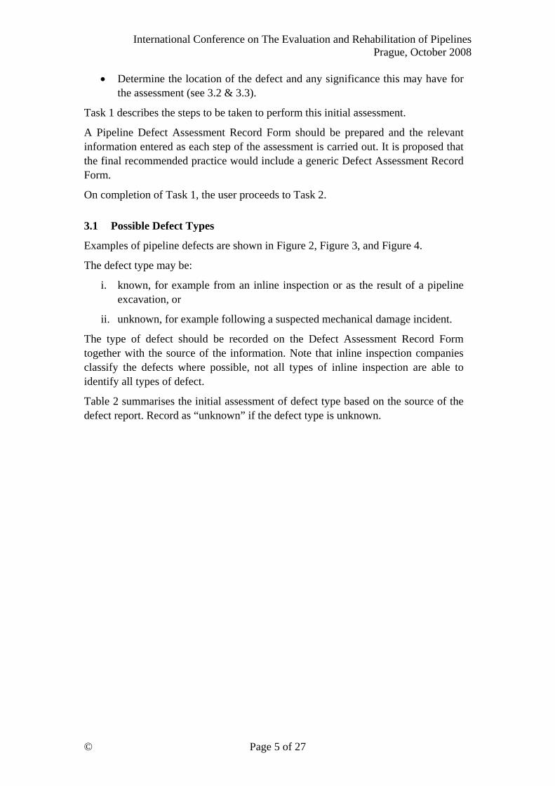
• Determine the location of the defect and any significance this may have for the assessment (see 3.2 & 3.3).
Task 1 describes the steps to be taken to perform this initial assessment.
A Pipeline Defect Assessment Record Form should be prepared and the relevant information entered as each step of the assessment is carried out. It is proposed that the final recommended practice would include a generic Defect Assessment Record Form.
On completion of Task 1, the user proceeds to Task 2.
3.1 Possible Defect Types
Examples of pipeline defects are shown in Figure 2, Figure 3, and Figure 4.
The defect type may be:
i. known, for example from an inline inspection or as the result of a pipeline excavation, or
ii. unknown, for example following a suspected mechanical damage incident.
The type of defect should be recorded on the Defect Assessment Record Form together with the source of the information. Note that inline inspection companies classify the defects where possible, not all types of inline inspection are able to identify all types of defect.
Table 2 summarises the initial assessment of defect type based on the source of the defect report. Record as “unknown” if the defect type is unknown.

International Conference on The Evaluation and Rehabilitation of Pipelines Prague, October 2008
© Page 6 of 27
Source of report Possible defect types
Reported or suspected external interference damage.
Dent
Gouge
Combined dent and gouge
Combination of dent & gouge with cracking
Other / Unknown
CP or coating anomalies
External corrosion
Environmental cracking
Other / Unknown
Inline inspection or
pipeline excavation
Internal corrosion
External corrosion
Girth weld defect
Manufacturing or construction defect
Lamination
Cracking
Dent
Gouge (identified as metal loss)
Other / Unknown
Table 2 Possible defect types

International Conference on The Evaluation and Rehabilitation of Pipelines Prague, October 2008
© Page 7 of 27
Figure 2 Example of external corrosion
Figure 3 Example of a dent
International Conference on The Evaluation and Rehabilitation of Pipelines Prague, October 2008
© Page 8 of 27
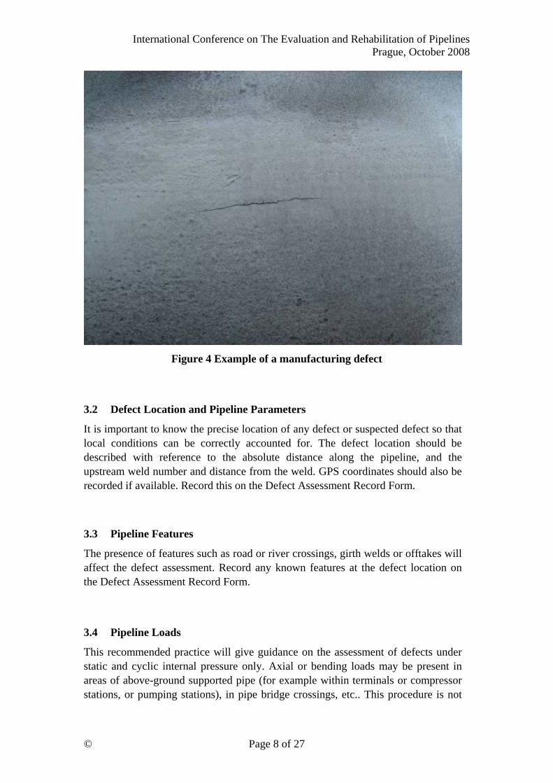
Figure 4 Example of a manufacturing defect
3.2 Defect Location and Pipeline Parameters
It is important to know the precise location of any defect or suspected defect so that local conditions can be correctly accounted for. The defect location should be described with reference to the absolute distance along the pipeline, and the upstream weld number and distance from the weld. GPS coordinates should also be recorded if available. Record this on the Defect Assessment Record Form.
3.3 Pipeline Features
The presence of features such as road or river crossings, girth welds or offtakes will affect the defect assessment. Record any known features at the defect location on the Defect Assessment Record Form.
3.4 Pipeline Loads
This recommended practice will give guidance on the assessment of defects under static and cyclic internal pressure only. Axial or bending loads may be present in areas of above-ground supported pipe (for example within terminals or compressor stations, or pumping stations), in pipe bridge crossings, etc.. This procedure is not

International Conference on The Evaluation and Rehabilitation of Pipelines Prague, October 2008
© Page 9 of 27
valid for defects in these areas: expert assistance should be sought, and this should be noted on the Defect Assessment Record Form.
If ground movement has occurred (e.g. due to landslide or seismic activity) this may have introduced axial or bending loads. If ground movement may have occurred, this should be noted on the Defect Assessment Record Form as additional inspection will be required as directed in Tasks 3 and 4.
The user now proceeds to Task 2
4 TASK 2: Pressure Reduction
An initial assessment of defect severity is necessary to determine whether a pressure reduction is required immediately to prevent failure of the pipeline, and whether pressure reductions are necessary during an on-site inspection to reduce the risk to inspection personnel, the public, and the environment.
Task 2 describes the process for deciding what pressure reductions are required. Any pressure reductions or other restrictions should be maintained until the damage has been assessed in Task 5. Note that a further pressure reduction may be necessary for certain repair methods.
The user also determines the requirements for pressure control, Table 3, and records and implements the decision on the Defect Assessment Record Form.
On completion of Task 2 the user proceeds to Task 3.

International Conference on The Evaluation and Rehabilitation of Pipelines Prague, October 2008
© Page 10 of 27
Damage Type
Requirements for immediate pressure control to prevent
failure.
Reduce the pressure to:1
Requirements for pressure reduction during
inspection.
Unknown – with suspicion of severe
damage from mechanical damage
incident.
Known cracking.
The lower of 80% of the maximum pressure seen since the defect was
introduced, and the pressure giving a hoop stress of 30% SMYS.
Unknown – reported or suspected minor
mechanical damage incident.
80% of the maximum pressure seen since the defect was introduced.
Known or inline inspection reported
dents or ovality.
None (subject to defect assessment, Task 5, and actions Task 6).
The lower of 80% of the maximum pressure seen since the defect was introduced, and
the pressure giving a hoop stress of 30% SMYS.
Known or Inline Inspection reported metal loss defect (or
manufacturing defect) in undented pipe
None (subject to defect assessment, Task 5, and actions Task 6).
Required pressure reduction is subject to outcome of defect
assessment, Task 5.
Known or Inline Inspection reported metal loss defect (or
weld defect) in dented pipe
The lower of 80% of the maximum pressure seen since the defect was
introduced, and the pressure giving a hoop stress of 30% SMYS.
The lower of 80% of the maximum pressure seen since the defect was introduced, and
the pressure giving a hoop stress of 30% SMYS.
CP or coating anomalies None (unless corrosion is present then refer to requirements for known metal
loss defect in undented pipe).
None (unless corrosion is present then refer to
requirements for known metal loss defect in undented pipe).
Table 3 Pressure reductions
4.1 Guidance on Pressure Reductions
The following should be considered when determining the requirements for pressure reduction, or other actions to control the hazard presented by a pipeline defect.
It is industry standard practice to reduce the operating pressure of a pipeline when severe, or potentially severe, defects are reported[2, 3]. The required level of pressure reduction is typically the lower of:
• 80% the maximum pressure seen since the defect was introduced (or reported), and
1 If the maximum operating pressure since the defect was reported was 90 barg, then 80% of the pressure would be 72 barg.

International Conference on The Evaluation and Rehabilitation of Pipelines Prague, October 2008
© Page 11 of 27
• The pressure giving a hoop stress of 30% SMYS at the defect location.
These two levels of pressure reduction are beneficial for distinct reasons:
• The reduction to 80% of the maximum pressure seen since the defect was reported introduces a margin of safety by limiting the stresses acting on the defect to 20% below the level that the defect has already survived. This therefore has the effect of reducing the probability that the defect will fail.
• Limiting the hoop stress to 30% SMYS reduces the consequences of failure should a loss of containment occur.
A pipeline defect may fail as a leak, or as a rupture. As a general rule, defects are unlikely to fail as a rupture where the hoop stress is less than 30% SMYS. The consequences of failure are more severe for a rupture than for a leak. Failure as a rupture is a dynamic event with a higher release of energy, which presents a greater hazard to people in the vicinity, compared with that from a leak. A rupture also results in significant deformation of the pipeline, with the potential for the damage to extend over several pipe lengths. The repair of an extended area of damage resulting from a rupture is therefore more complex and costly than that of a leak.
Note that in some cases of extreme pipeline damage; for example, those resulting in gross displacement of the pipeline, reducing the pipeline pressure may not have the effect of reducing the stresses driving failure.
The user then proceeds to Task 3
5 TASK 3: Need For Site Inspection
For some defects, site inspection is required to confirm the types of defect present and to quantify the dimensions of any damage found. For other defects, categorisation can be performed without additional site inspection.
Task 3 describes the procedure for determining whether site inspection is required before defect categorisation can be performed. On completion of Task 3, the user proceeds to Task 4 or 5 as directed.
Determine whether site inspection is recommended. Proceed to the Task recommended in Table 4. If site inspection is not performed, categorise defect without inspection, as defined in Table 4. Record and implement the decision on the Defect Assessment Record Form.

International Conference on The Evaluation and Rehabilitation of Pipelines Prague, October 2008
© Page 12 of 27
Defect Type Categorisation Without Site Inspection
Recommended next Task
• Known gouges.
• Known cracking.
• Suspected defects, or defects for which dimensions are unknown.
• Defects in dented pipe.
• Defects identified as being in areas of landslide or seismic activity.
SEVERE
Site inspection
Task 4
• Dents of known size. According to Task 5 Site inspection
Task 4
• Known corrosion in undented pipe (reported by inline inspection).
• Known manufacturing defects in undented pipe.
According to Task 5
Defect assessment and categorisation
Task 5
Table 4 Requirement for site inspection and recommended next task
6 TASK 4: Site Inspection
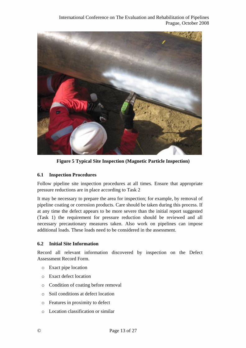
Site inspection will provide valuable information of the nature and dimensions of a defect. A typical example of site inspection is shown in Figure 5.
Task 4 describes the information to be gathered during site inspection.
Note that this is not a defect inspection procedure. An appropriate procedure for site inspection should be followed to ensure safe working and to ensure that suitable inspection methods are employed.
On completion of Task 4, the user proceeds to Task 5.
International Conference on The Evaluation and Rehabilitation of Pipelines Prague, October 2008
© Page 13 of 27
Figure 5 Typical Site Inspection (Magnetic Particle Inspection)
6.1 Inspection Procedures
Follow pipeline site inspection procedures at all times. Ensure that appropriate pressure reductions are in place according to Task 2
It may be necessary to prepare the area for inspection; for example, by removal of pipeline coating or corrosion products. Care should be taken during this process. If at any time the defect appears to be more severe than the initial report suggested (Task 1) the requirement for pressure reduction should be reviewed and all necessary precautionary measures taken. Also work on pipelines can impose additional loads. These loads need to be considered in the assessment.
6.2 Initial Site Information
Record all relevant information discovered by inspection on the Defect Assessment Record Form.
o Exact pipe location
o Exact defect location
o Condition of coating before removal
o Soil conditions at defect location
o Features in proximity to defect
o Location classification or similar
International Conference on The Evaluation and Rehabilitation of Pipelines Prague, October 2008
© Page 14 of 27
For defects identified in Task 1 as being in areas of landslide or seismic activity, inspection is required to confirm that no pipe movement or significant ground movement has occurred. If there is any indication of such movement then the methods in this procedure may not be valid and Expert Assistance must be sought.
6.3 Defect Type Identification
It is important to identify all the defect types present at the location. Damage that is a combination of defect types is likely to be more severe than a single defect type.
Record which of the following are present2, on the Defect Assessment Record Form.
o Corrosion
o Gouge
o Plain dent
o Kinked dent
o Cracking
o Manufacturing and construction defects
o Weld defects
Photograph or sketch the general arrangements of the defects.
6.4 Defect Details and Dimensions
For each defect type present, measure and record defect dimensions and orientation on a Defect Assessment Record Form.
o Corrosion (see required details below)
o Gouge (not included in this outline)
o Plain dent (not included in this outline)
o Kinked dent (not included in this outline)
o Cracking (not included in this outline)
o Manufacturing and construction defects (not included in this outline)
o Weld defects (not included in this outline)
Where possible, photograph or otherwise permanently record the defect.
2 Gouges, dents and cracking can be associated with mechanical damage. Hence if one of these damage types is reported, inspection should be made for the others.

International Conference on The Evaluation and Rehabilitation of Pipelines Prague, October 2008
© Page 15 of 27
6.5 Corrosion
Information to be recorded for corrosion defects:
o Internal or external.
o Description:
• Isolated corrosion pit.
• Multiple corrosion pits.
• General corrosion.
• General corrosion with pitting.
• Preferential weld corrosion.
o Length (axial), L mm
Depth, d mm (See Figure 6). (by UT or gauge as available)
Width (circumferential), W mm
o Orientation around the pipe circumference (o’clock facing downstream), (See Figure 7).
UT measurement of undamaged wall thickness local to defect, tL mm, if available.

International Conference on The Evaluation and Rehabilitation of Pipelines Prague, October 2008
© Page 16 of 27
Figure 6 Dimensions of metal loss defect (corrosion)
L
w t
L
W
d

International Conference on The Evaluation and Rehabilitation of Pipelines Prague, October 2008
© Page 17 of 27
Figure 7 Defect Orientation (Facing down-stream)
The critical dimensions to be recorded for other defects would be included in the full Recommended Practice – plus data to record for checking interaction.
7 TASK 5: Defect Assessment
Defects in a pipeline must be assessed to determine whether they affect the integrity of the pipeline.
Procedures will be given to categorise the following types of defect:
• External and internal corrosion
• Gouges
• Gouges on welds
• Plain dents3
• Smooth dents on welds
• Smooth dents containing a gouge
3 A plain dent is a smooth dent which contains no wall thickness reduction and does not interact with any other feature or alter the curvature of an adjacent girth or seam weld.
9 o’clock
12 o’clock
6 o’clock
3 o’clock

International Conference on The Evaluation and Rehabilitation of Pipelines Prague, October 2008
© Page 18 of 27
• Kinked dents
• Cracking and crack-like defects
• Weld defects
• Manufacturing and construction defects
(In this draft recommended practice a procedure for assessing corrosion features is proposed.)
If defects other than those listed above are reported, or if there is loading other than internal pressure (static and cyclic), then expert assistance will be required, and defects should be categorised as Severe.
The procedures are applicable to defects in straight pipe and large radius cold formed bends. Defects in fittings such as fabricated bends and tees cannot be assessed using this recommended practice.
Task 5 describes the procedures for assessing and categorising defects. On completion of Task 5, the user proceeds to Task 6.
International Conference on The Evaluation and Rehabilitation of Pipelines Prague, October 2008
© Page 19 of 27
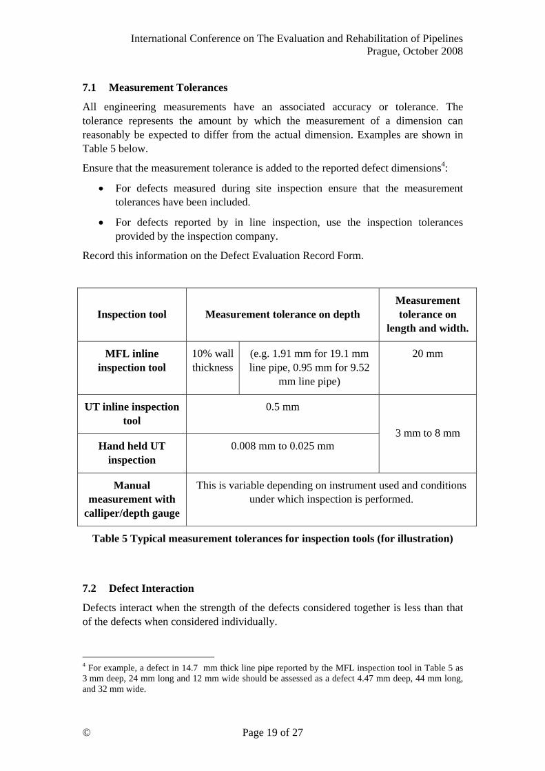
7.1 Measurement Tolerances
All engineering measurements have an associated accuracy or tolerance. The tolerance represents the amount by which the measurement of a dimension can reasonably be expected to differ from the actual dimension. Examples are shown in Table 5 below.
Ensure that the measurement tolerance is added to the reported defect dimensions4:
• For defects measured during site inspection ensure that the measurement tolerances have been included.
• For defects reported by in line inspection, use the inspection tolerances provided by the inspection company.
Record this information on the Defect Evaluation Record Form.
Inspection tool Measurement tolerance on depth Measurement tolerance on
length and width.
MFL inline inspection tool
10% wall thickness
(e.g. 1.91 mm for 19.1 mm line pipe, 0.95 mm for 9.52
mm line pipe)
20 mm
UT inline inspection tool
0.5 mm
Hand held UT inspection
0.008 mm to 0.025 mm 3 mm to 8 mm
Manual measurement with
calliper/depth gauge
This is variable depending on instrument used and conditions under which inspection is performed.
Table 5 Typical measurement tolerances for inspection tools (for illustration)
7.2 Defect Interaction
Defects interact when the strength of the defects considered together is less than that of the defects when considered individually.
4 For example, a defect in 14.7 mm thick line pipe reported by the MFL inspection tool in Table 5 as 3 mm deep, 24 mm long and 12 mm wide should be assessed as a defect 4.47 mm deep, 44 mm long, and 32 mm wide.

International Conference on The Evaluation and Rehabilitation of Pipelines Prague, October 2008
© Page 20 of 27
Recommendations to allow the user to evaluate the potential for defect interaction would be included in the full Recommended Practice.
7.3 External or Internal Corrosion
This assessment method is applicable to the assessment of isolated corrosion defects, and to the assessment of interacting corrosion defects, and corrosion defects interacting with weld defects.
The severity of corrosion features depends primarily on their length (axial) and depth. Deep and long features are more severe than shallow, short features.
Corrosion features with significant width (circumferential) may also reduce the strength of the pipeline. These are not considered in this draft Recommended Practice
The method used is based on assessment against internal pressure loads and is in accordance with ASME B31.G[4].
7.4 Preliminary Calculations
1. Calculate the normalised depth parameter, the ratio of the defect depth to the pipe wall thickness:
dnorm = td ,
where:
d = defect depth (including measurement tolerance)
t = un-corroded pipe wall thickness
record dnorm on a Defect Assessment Record Form
Calculate the normalised non-dimensional defect length parameter:
Lnorm = tD
L⋅
Where:
L = defect length (measured longitudinal extent of the corroded area, including any measurement tolerance)
D = pipe diameter (external)
t = un-corroded pipe wall thickness

International Conference on The Evaluation and Rehabilitation of Pipelines Prague, October 2008
© Page 21 of 27
7.5 Categorisation of Defects: Severe, Moderate, Superficial
Plot Lnorm against dnorm for the feature on Figure 8, find the initial defect category5, and record the result on the Defect Assessment Record Form. Note that a full page copy of Figure 8 suitable for including in any record of the defect assessment would be provided in the final recommended practice.
0
0.1
0.2
0.3
0.4
0.5
0.6
0.7
0.8
0.9
0 1 2 3 4 5 6
L_norm
d_no
rm
Figure 8 Initial Corrosion Defect Categorisation
Read the final corrosion defect category from Table 6, and record on the Defect Assessment Record Form.
5 The ‘initial’ defect category is the category as defined by the first stage of the assessment. For some defects it will be possible to identify the ‘final’ categorisation immediately, for others secondary checks such as proximity to a weld are required to confirm the ‘final’ category
Initial SUPERFICIAL
Initial MODERATE
Initial SEVERE

International Conference on The Evaluation and Rehabilitation of Pipelines Prague, October 2008
© Page 22 of 27
Initial Defect Category (from
Figure 8)
Corrosion coincident with, or interacting with1 a weld that cannot be confirmed to be
defect-free, over-matched and of high toughness?
Final Defect Category
Yes Initial SEVERE
No SEVERE
Yes SEVERE Initial
MODERATE No MODERATE
Yes MODERATE Initial
SUPERFICIAL No SUPERFICIAL Notes:
1. The interaction has not been defined in this outline recommended practice. It is proposed that the interaction distance will be the maximum dimension (length or width) of the smaller of any two defects.
Table 6 Final Defect Categorisation for Corrosion

International Conference on The Evaluation and Rehabilitation of Pipelines Prague, October 2008
© Page 23 of 27
8 TASK 6: Repair and Follow-Up Actions
The actions to be taken following the defect assessment depend on the final categorisation.
8.1 Actions for Superficial Defects
Defects categorised as ‘Superficial’ have no immediate effect on the integrity of the pipeline and have an operational safety factor equivalent to the design safety factor.
For defects categorised as Superficial the following actions should be taken:
• The pipeline should be recoated if necessary, and the pipeline reinstated.
• No further repair is required.
• If the defect is the result of corrosion, the corrosion mechanism should be arrested or the defect monitored.
• The pipeline pressure can be returned to MAOP.
• Should any future defects occur at the same location then the presence of the original defect must be considered in the assessment.

International Conference on The Evaluation and Rehabilitation of Pipelines Prague, October 2008
© Page 24 of 27
8.2 Actions for Moderate Defects
Defects categorised as ‘Moderate’ have no immediate impact on the integrity of the pipeline, but are considered unsafe if left for the long term.
For defects categorised as Moderate, the following actions should be taken:
• For Moderate defects, repair should be carried out, or the results of expert assessment received within 6 months of the defect report6.
If the categorisation has been reached without site inspection, the site inspection may be performed in accordance with Task 4, and the defect recategorised according to Task 5. This should be completed within 6 months of the defect report.
• Any pressure reduction should be maintained pending expert assessment and/or repair.
• If expert assessment has been requested, this may impose or remove pressure limitations.
• If the defect is the result of corrosion, the corrosion mechanism should be arrested or the defect monitored.
• Once repair is complete, the pipeline pressure can be returned to MAOP.
6 6 months is considered to be a practical timescale for the scheduled response to a significant pipeline defect, not at the failure point; this is based on guidance in ASME B318S[2]. The decision is left to the engineer responsible for the pipeline integrity whether to repair immediately or to refer the defect for further expert assessment (or further inspection). This decision will depend on:
• The relative cost of repairing the defect while the pipeline is exposed at the inspection site (if onsite inspection has been performed) compared with the cost of a separate visit for repair.
• How many other defects there are at the location which could be repaired at the same time. • The relative severity of the defect (whether it is closer to the Red or Yellow category limit).
Also note that the assessments in this procedure are likely to be conservative, and that expert assessment may therefore revise the categorisation if there is significant interaction between metal loss features.

International Conference on The Evaluation and Rehabilitation of Pipelines Prague, October 2008
© Page 25 of 27
8.3 Actions for Severe Defects
Defects categorised as ‘Severe’ are considered to have an immediate impact on the integrity of the pipeline.
For defects categorised as Severe, the following actions should be taken:
• Repairs of Severe defects should be carried out within 30 days7 of receiving the defect report.
Alternatively:
o Urgent referral for expert assessment may be made if results can be received and actions taken within the 30 day limit.
o If the categorisation has been reached without site inspection, the site inspection may be performed in accordance with Task 4, and the defect recategorised according to Task 5. This should be completed within 30 days of the defect report.
• Pressure in the pipeline should be reduced to the minimum of 80% of the maximum pressure seen since the defect was reported8, and the pressure to give a hoop stress of 30% SMYS at the defect location (see Task 2).
• If expert assessment has been requested, this may impose or remove pressure limitations.
• If the defect is the result of corrosion, the corrosion mechanism should be arrested or the defect monitored.
• Once repair is complete, the pipeline pressure can be returned to MAOP.
7 30 days is considered a practical time limit for the repair of severe defects; this is in line with guidance in API 1160[5].
8 If the maximum operating pressure since the defect was reported were 90 barg, then 80% of this pressure would be 72 barg.

International Conference on The Evaluation and Rehabilitation of Pipelines Prague, October 2008
© Page 26 of 27
8.4 Repair Selection
There will be ‘Recommended Practice’ algorithms in the proposed document for the selection of an appropriate repair for the type of damage. An example for corrosion is shown in Figure 9.
Figure 9 Example Repair Selection: Corrosion
An example of a composite wrap repair is shown in Figure 10.
Internal
Corrosion defect (Moderate or
Severe)
External
Depth > 80% t Pressure containing
steel sleeve
Pressure containing steel
sleeve
Composite Wrap
no yes

International Conference on The Evaluation and Rehabilitation of Pipelines Prague, October 2008
© Page 27 of 27
Figure 10 Composite wrap repair
9 Way Forward This outline recommended practice is intended to provoke discussion on the need for a generic pipeline defect assessment and repair document, and provide the starting point for a Joint Industry Project to develop this document. The next step is to hold a meeting of interested parties to discuss the likely scope of any project, and the form of the proposed recommended practice. Any parties interested in attending a scoping meeting and being involved in this project should contact the author: Roland Palmer-Jones Penspen Ltd Units 7&8 terrace level St Peters Wharf Newcastle upon Tyne NE6 1TZ email: [email protected] tel: +44 (0) 191 238 2201
10 References
1. Cosham, A.C. and Hopkins, P. “The Pipeline Defect Assessment Manual (PDAM), A Report to the Joint Industry Project.” Penspen report NR00018/4238.1.10/R1.01 May 2003.
2. Anon, ‘Managing System Integrity of Gas Pipelines’, ASME B31.8S-2004 3. Jaske Carl, E., Hart Brian, O., Bruce Shouldiam, A., “Pipeline Repair
Manual”, Pipeline Research Council International, Inc (PRCI), Prepared by CC Technologies, Inc. & Edison Welding Institute, Contract PR 186-0324, August 2006
4. Anon, “Manual for Determining the Remaining Strength of Corroded Pipelines”. A Supplement to ASME B31 Code for Pressure Piping, ANSI/ASME B31G-1984, The American Society of Mechanical Engineers, New York, USA, 1984.
5. Anon, “Managing System Integrity for Hazardous Liquid Pipelines”, API Standard 1160, First Edition, November 2001.