penspen subsea pipeline damage assessment and repair.ppt - subsea europe 2010.pdf · safety –...
TRANSCRIPT

1
Subsea PipelinesAnchor Damage Assessment and Repair
A O i f M th d d Li it tiAn Overview of Methods and Limitations With A Case Study From the BP CATS
Pipeline
Roland Palmer-Jones
© Penspen Ltd 2010
Penspen Integrity, UK
SUBSEA EUROPE 2010 Paris
Outline
Challenges Safety – pressure reductions
Assessment Stages
Typical Damage
Inspection Options/Limitations
Assessment Methods/Limitations
Repair Options
© Penspen Ltd 2010
Case Study
2
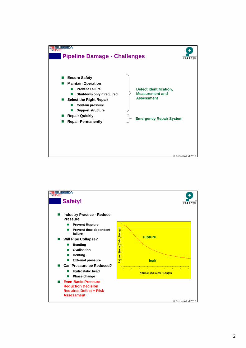
Pipeline Damage - Challenges
Ensure Safety
M i t i O ti Maintain Operation
Prevent Failure
Shutdown only if required
Select the Right Repair
Contain pressure
Support structure
Repair Quickly
Defect Identification, Measurement and Assessment
Emergency Repair System
© Penspen Ltd 2010
Repair Permanentlyg y p y
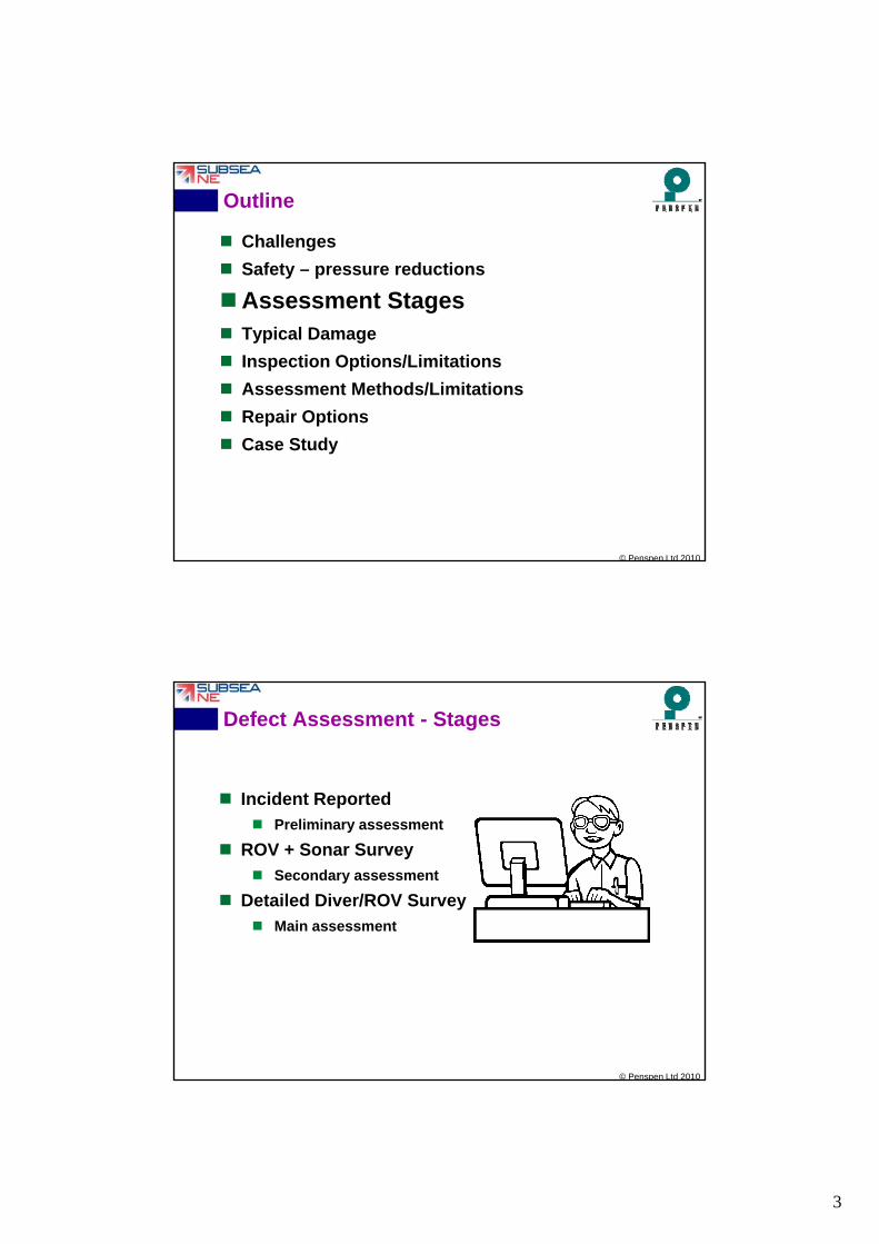
Safety!
Industry Practice - Reduce Pressure
Prevent Rupture1.2
h
Prevent time dependent failure
Will Pipe Collapse?
Bending
Ovalisation
Denting
External pressure
Can Pressure be Reduced?
0.2
0.4
0.6
0.8
1
Fai
lure
Str
ess/
Yie
ld S
tren
gth
leak
rupture
© Penspen Ltd 2010
Can Pressure be Reduced?
Hydrostatic head
Phase change
Even Basic Pressure Reduction Decision Requires Defect + Risk Assessment
0
0 1 2 3 4 5 6 7 8
Normalised Defect Length
3
Outline
Challenges
Safety – pressure reductions
A t StAssessment Stages Typical Damage
Inspection Options/Limitations
Assessment Methods/Limitations
Repair Options
© Penspen Ltd 2010
Case Study
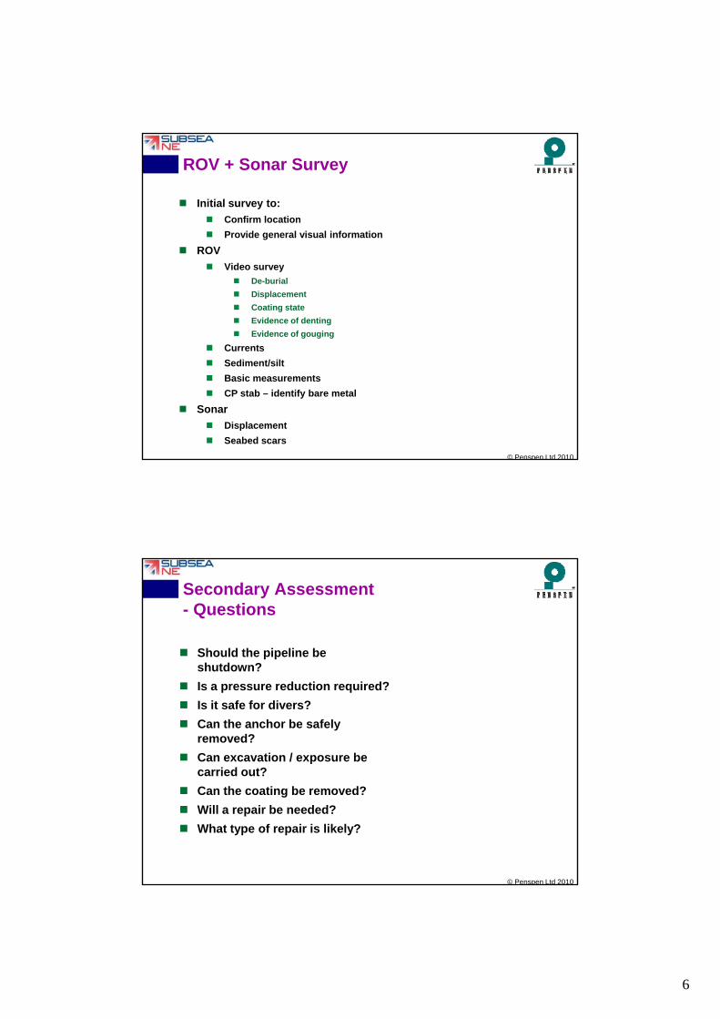
Defect Assessment - Stages
Incident Reported
Preliminary assessment
ROV + Sonar Survey Secondary assessment
Detailed Diver/ROV Survey Main assessment
© Penspen Ltd 2010

4
Preliminary Assessment - Questions
Incident Reported
Shi i Ship reports snagging
ILI report indicates dent and gouge
Sonar/ROV survey indicates damage
Preliminary Assessment Questions
Should the pipeline be shutdown?
© Penspen Ltd 2010
Is a pressure reduction required?
Is it safe for a vessel to approach?
Will a repair be needed?
What type of repair is likely?
Preliminary Assessment - Data
Incident details
Location,
Ship speed,Ship speed,
Was anchor abandoned on Pipeline?
Did anchor chain break?
Leak?
Ship details
Tonnage,
Anchor size/weight,
Anchor chain weight/breaking strain.
Pipeline details
© Penspen Ltd 2010
Pipeline details
Diameter,
Wall thickness,
Material,
Coatings,
Depth of burial,
Operating pressure.
5
Preliminary Assessment - Approach
Calculate Damage Resistance
Dent Depth vs Impact Energy
3
2 De-burial vs Ship kinetic energy
Bending vs Ship kinetic energy
Calculate Available Energy for Damage
Anchor + chain weight and velocity
Concrete crushing
Local denting
Ed
2100 m p
OD
© Penspen Ltd 2010
Local denting
Ship mass and velocity
Pipeline de-burial
Global deformation/bending
Preliminary Assessment - Potential Conclusions
Significant damage not credible (Small ship + Large pipeline)pipeline)
No immediate pressure reduction
Proceed with ROV survey
Review repair readiness
Significant damage possible (Large ship + Large pipeline)
Reduce pressure
Mobilise emergency repair system (grouted sleeve)
© Penspen Ltd 2010
Mobilise emergency repair system (grouted sleeve)
Proceed with ROV
Significant damage likely (Large ship + Small pipeline)
Shutdown or significantly reduce pressure
Mobilise emergency repair (mechanical connectors)
Proceed with ROV
6
ROV + Sonar Survey
Initial survey to:
Confirm location
Provide general visual information
ROV
Video survey
De-burial
Displacement
Coating state
Evidence of denting
Evidence of gouging
Currents
© Penspen Ltd 2010
Cu e ts
Sediment/silt
Basic measurements
CP stab – identify bare metal
Sonar
Displacement
Seabed scars
Secondary Assessment- Questions
Should the pipeline be shutdown?shutdown?
Is a pressure reduction required?
Is it safe for divers?
Can the anchor be safely removed?
Can excavation / exposure be carried out?
© Penspen Ltd 2010
carried out?
Can the coating be removed?
Will a repair be needed?
What type of repair is likely?

7
Secondary Assessment
‘Global’ Stress analysis of snagging/displacement to
l t t diti
Tension
B di Bending
As-laid Pipeline
Displaced Pipeline
evaluate stress condition
Span assessment
Stability
Identify ‘likely’ local damage type:
Plain dent
Dent on weld
CompressionBending Bending
Direction of Anchor Impact & Drag
Axial defect (fixed width, 20mm), axial compression, internal pressure (55 bar) DNV
-2701.0mm Defect Depth2.0mm3.0mm
© Penspen Ltd 2010
Dent on weld
Dent plus gouge
Gouge only
Calculate critical damage sizes
Identifies measurements required
-260
-250
-240
-230
-220
-210
0 100 200 300 400 500 600 700 800 900 1000
Axial Defect Length 2c (mm)
'saf
e' a
llow
ab
le t
ota
l axi
al c
om
pre
ssi
on
(M
Pa
)
4.0mm5.0mm6.0mm7.0mm8.0mm
Diver Survey
Excavate
Remove coating
D t il d i l i ti Detailed visual inspection
Geometric inspection
Magnetic Particle Inspection
Ultrasonic inspection
© Penspen Ltd 2010
Ultrasonic inspection

8
Final Assessment- Questions
Should the pipeline be shutdown?
Is a pressure reduction required?
Will a repair be needed?
What type of repair?
© Penspen Ltd 2010
Final Assessment
Assess local damage
Burst pressure
Oil Pipeline Pressure history
800
1000
1200
1400
ure
(p
si)
Burst pressure
Fatigue life
Operational restrictions
Basis of assessment Industry guidance/experience
FEA
0
200
400
600
22-Mar 23-Mar 24-Mar 25-Mar 26-Mar 27-Mar 28-Mar 29-Mar 30-Mar 31-Mar 01-Apr 02-Apr
Time
Pre
ssu
© Penspen Ltd 2010
Include effects of displacement
Damage behaviour and failure mechanism Repair performance requirements

9
Outline
Challenges
Safety – pressure reductions
Assessment Stages Assessment Stages
Typical Damage
Inspection Options/Limitations
Assessment Methods/LimitationsR i O ti
© Penspen Ltd 2010
Repair Options
Case Study
Typical (Possible) Damage
Rupture
Gouge
Displacement
Plain Dent
Dent Plus Displacement
© Penspen Ltd 2010
Dent on Weld
Dent and Gouge
Kinked Dent
10
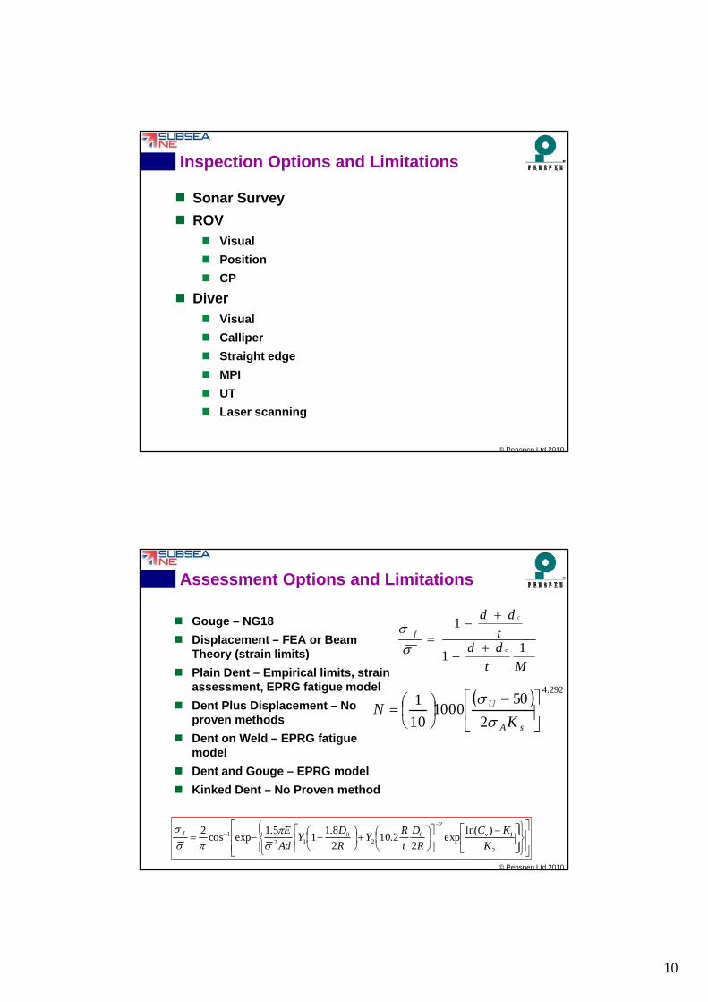
Inspection Options and Limitations
Sonar Survey
ROV
Vi l Visual
Position
CP
Diver Visual
Calliper
© Penspen Ltd 2010
Straight edge
MPI
UT
Laser scanning
Assessment Options and Limitations
Gouge – NG18
Displacement – FEA or Beam Theory (strain limits) dd
tdd
c
c
f
11
1
Theory (strain limits)
Plain Dent – Empirical limits, strain assessment, EPRG fatigue model
Dent Plus Displacement – No proven methods
Dent on Weld – EPRG fatigue model
Mt1
2
501000
10
1292.4
sA
U
KN
© Penspen Ltd 2010
Dent and Gouge – EPRG model
Kinked Dent – No Proven method
2
1
2
02
012
1 )ln(exp
22.10
2
8.11
5.1expcos
2
K
KC
R
D
t
RY
R
DY
Ad
E vf

11
Offshore Pipeline Repair Options
Grinding
Clamps / Sleeves
Section Replacement Connectors
Hyperbaric welding
Recovery to
© Penspen Ltd 2010
Recovery to surface
Outline
Challenges
Safety – pressure reductions
Assessment Stages Assessment Stages
Typical Damage
Inspection Options/Limitations
Assessment Methods/Limitations
Repair Options
© Penspen Ltd 2010
Case Study
12
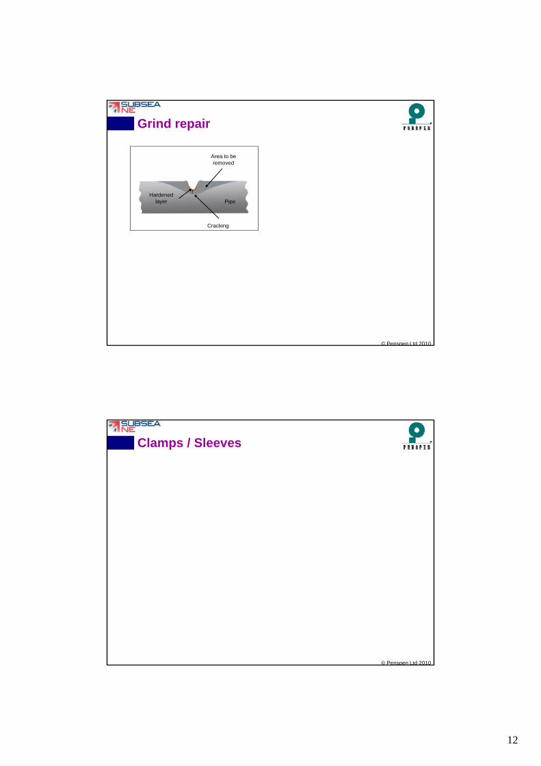
Grind repair
Area to be removed
Pipe
Cracking
Hardened layer
© Penspen Ltd 2010
Clamps / Sleeves
© Penspen Ltd 2010
13
Section Replacement
© Penspen Ltd 2010
Outline
Challenges
Safety – pressure reductions
Assessment Stages Assessment Stages
Typical Damage
Inspection Options/Limitations
Assessment Methods/Limitations
Repair Options
© Penspen Ltd 2010
Case Study
14
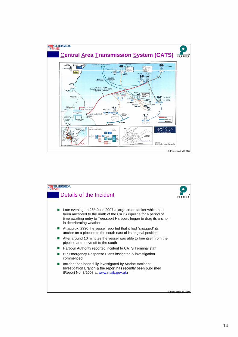
Central Area Transmission System (CATS)
© Penspen Ltd 2010
Details of the Incident
Late evening on 25th June 2007 a large crude tanker which had been anchored to the north of the CATS Pipeline for a period of time awaiting entry to Teessport Harbour, began to drag its anchor in deteriorating weather
At approx. 2330 the vessel reported that it had “snagged” its anchor on a pipeline to the south east of its original position
After around 10 minutes the vessel was able to free itself from the pipeline and move off to the south
Harbour Authority reported incident to CATS Terminal staff
BP Emergency Response Plans instigated & investigation
© Penspen Ltd 2010
commenced
Incident has been fully investigated by Marine Accident Investigation Branch & the report has recently been published (Report No. 3/2008 at www.maib.gov.uk)
15
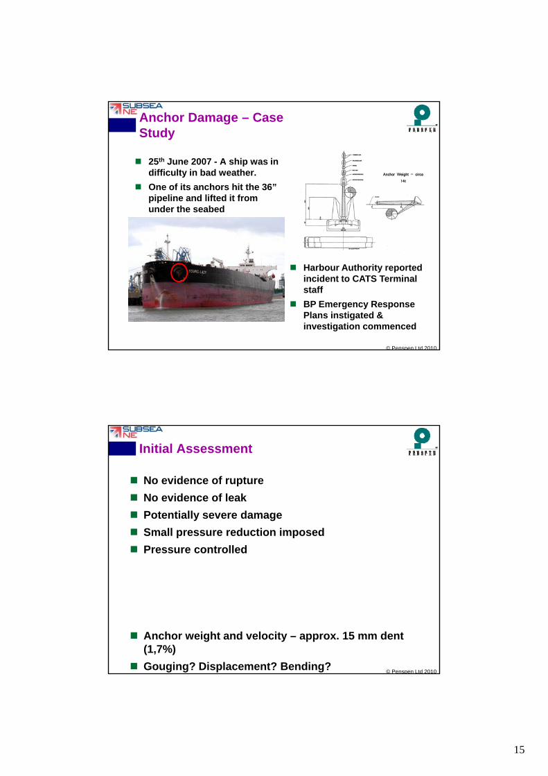
Anchor Damage – Case Study
25th June 2007 - A ship was in difficulty in bad weather.
O f it h hit th 36”
Anchor Weight – circa 14t
One of its anchors hit the 36” pipeline and lifted it from under the seabed
Harbour Authority reported
© Penspen Ltd 2010
Harbour Authority reported incident to CATS Terminal staff
BP Emergency Response Plans instigated & investigation commenced
Initial Assessment
No evidence of rupture
No evidence of leak
Potentially severe damage
Small pressure reduction imposed
Pressure controlled
© Penspen Ltd 2010
Anchor weight and velocity – approx. 15 mm dent (1,7%)
Gouging? Displacement? Bending?
16
ROV Survey
Initial reports showed concrete damage, bending,damage, bending, gouging, and denting
© Penspen Ltd 2010
Secondary Assessment
Apparently severe damage
Dent gouge calculations indicate failure pressure below design for credible combinations.
P d ti i d
© Penspen Ltd 2010
Pressure reduction required
Review repair options

17
Investigation of Repair options
BP Project Team established & dedicated to the repair.
Do nothing or dress defect, assess and leave
following repair options reviewed in parallel with inspection activities
© Penspen Ltd 2010
Wet weld, metal build up
Deploy existing BP clamp / identify alternatives across the globe
Replace section with subsea connectors
Replace section with hyperbaric welds
Lift pipe and re-lay section with lay barge and tie-in
Re-lay new section with lay barge and tie-in
Detailed Inspection / Work Program
1. Pipeline depressurisation (in controlled stages from 113 barg to 54 barg) to enable safe diver access
2. Diverless excavation of pipeline and further ROV inspection2. Diverless excavation of pipeline and further ROV inspection
3. Final excavation of pipe spool (approx. 20m)
4. Concrete & Coal Tar Coating removal (approx. 14m)
5. Detailed Diver Inspection- Close visual inspection
- Out of Straightness survey
- Ovality Survey
- Taut Wire
© Penspen Ltd 2010
- Magnetic Particle Inspection (welds & defect areas)
- Ultrasonic Inspection (welds & defect areas) – automated and manual

18
Inspection Results
• 1.5m vertical displacement
• 4.5m horizontal displacement
• Damage over a 4m length in middle• Damage over a 4m length in middle of spool
• 2 Dents within a larger deformed area
© Penspen Ltd 2010
2 Dents within a larger deformed area
• 31mm and 25mm max. depth (3.4%D)
• 2 Protrusions of max. 15mm
• Weld deformed
• No weld defects / cracking
• No gouging
Final Defect Assessment
Defects were assessed using the Pipeline Defect Assessment Manual (PDAM)
Limitations: No method for combined No method for combined
dent and external load. Limited test data for large
diameter offshore pipelines.
FEA of displacement. FEA of dented area EPRG dent fatigue Terminal Inlet Pressure (Previous 12 Months)
123
125
© Penspen Ltd 2010
105
107
109
111
113
115
117
119
121
Time
Pre
ssu
re (
bar
)
19
Results of Defect Assessment
Analysis Findings: No reduction in static strength of pipeline
Fatigue life of pipeline reduced by dents on weld
Repair Decision: Existing sleeve would not fit (too short and pipe bent)
Structural, cement grouted sleeve repair selected to provide reinforcement of dented area
© Penspen Ltd 2010
How long did it take?
Incident occurred - 25 June
Initial survey complete – 30 June
Pipeline shutdown – 1 July Pipeline shutdown 1 July
Pipe depressurised and safe to dive – 18 July
Detailed inspection complete – 28 July
Go ahead for sleeve fabrication – 29 July
Sleeve Fabrication / Fit-Up Trials complete - 17 August
Diving Support Vessel on location - 18 August
Pipeline recommissioning commenced - 24 August
© Penspen Ltd 2010
p g g
Delivery of on-spec gas - 1 Sept
Rock dump complete – 2 Oct
20
Cross-industry support to release vessels during peak summerperiod – both from operators and contractors
Fantastic support & dedication from key contractors with whomBP already had long term relationships Technip Acergy RBG
Critical Success Factors
BP already had long term relationships – Technip, Acergy, RBG,JP Kenny, Penspen/APA, Jee, Foundocean, Subsea 7 andothers
Rapid mobilization of dedicated project team from BP &contractors
Existing relations with BP global experts simplified assuranceprocesses
Clear accountabilities within Project Team – Pipeline Integrity,Subsea Activities Terminal Ops Sleeve Fabrication JV and
© Penspen Ltd 2010
Subsea Activities, Terminal Ops, Sleeve Fabrication, JV andReputation Management
Strong engagement with regulators from Day 1
HIGH QUALITY, PERMANENT PIPELINE REPAIR SAFELY IMPLEMENTED IN LESS THAN 3
MONTHS
Summary
There are stages to damage assessment
Uncertainties at each stage
Data changes
Need to use all available data
Specialist skills/experience needed
Contingency plans/repairs may not be appropriate
Proven methods for assessment may not be available
Caution is needed
© Penspen Ltd 2010

21
Repair Management
Pipeline operator
Vessel operator
Diving contractor
ROV operator ROV operator
NDT contractor
Defect specialists
Welding
Re-commissioning
Subsea designer
Verification agency/consultant
Equipment suppliers Pipe handling
© Penspen Ltd 2010
Pipe handling
Concrete removal
Pipe cutting
Clamp or connectors
Welding habitat
Isolation tools
De-watering pigs
Regulator
REPAIR: Caution.
Some wise words on repair*: ‘Do no harm!’
A bad repair can makeA bad repair can make matters worse.
Repairs need careful engineering, at least as much as a new construction.
Do not act in haste.
A repair is often not a good time to try something new.
© Penspen Ltd 2010
g
There is less experience with a new procedure, compared to tried and tested designs. Surprises may occur with uncertainty and incompletely planned engineering
*A C Palmer, R King, ‘Subsea Pipeline Engineering’, Penwell. 2004.