this catalog covers verco - pacific metal deckpacificmetaldeck.com/documents/verco_floor.pdf ·...
TRANSCRIPT

This catalog covers Verco Decking, Inc.’s FORMLOK™ composite decks and VERCOR™ non-composite form decks. It also features the innovative PunchLok® System for floor deck applications. By significantly speeding up installation and reducing costs, Verco’s PunchLok System has been proven time and again to be the most efficient deck attachment system on the market.
Our philosophy from the beginning has been to produce high quality products and our employees take pride in their dedication to excellence and superior service. We carefully design and test our products to ensure they meet code requirements and exceed our customers’ expectations.
Verco’s manufacturing facilities are located in Phoenix, Arizona, and the California cities of Fontana and Antioch.
Phosphatized/painted W2 FORMLOKTM deck (illustrated)offers the most economical solution for most applications.
Verco’s products are listed in evaluation reports issued by IAPMO Evalu-ation Service, ICC Evaluation Service, and the City of Los Angeles, and in the Fire Resistance Directory issued by Underwriters Laboratory. Addition-al information is available from Verco’s Engineering Department or from the Verco website at www.vercodeck.com.
Catalog VF4 Copyright © 2001 - 2012 Verco Decking, Inc. All Rights Reserved

www.vercodeck.com VERCO DECKING, INC. Catalog VF4
PROFILES AND PROPERTIES . . . . . . . . . . . . . . . . . . .2
TECHNICAL GUIDELINES . . . . . . . . . . . . . . . . . . . . . .5
PLB™ and B FORMLOK™ DECK . . . . . . . . . . . . . . . . .36Deck Weight and Section PropertiesAllowable Superimposed LoadsAllowable Diaphragm Shear Values and Flexibility Factors
PLW2™ and W2 FORMLOK™ DECK . . . . . . . . . . . . . .46Deck Weight and Section PropertiesAllowable Superimposed LoadsAllowable Diaphragm Shear Values
PLW3™ and W3 FORMLOK™ DECK . . . . . . . . . . . . . .56Deck Weight and Section PropertiesAllowable Superimposed LoadsAllowable Diaphragm Shear Values
PLN™ and N FORMLOK™ DECK . . . . . . . . . . . . . . . . .66Deck Weight and Section PropertiesAllowable Superimposed LoadsAllowable Diaphragm Shear Values and Flexibility Factors
PLW2™ and W2, PLW3™ and W3 DECK–NO FILL . . .76Technical DataAllowable Uniform LoadsAllowable Diaphragm Shear Values and Flexibility Factors
VERCOR™ NON-COMPOSITE FORM DECK . . . . . . .86Technical DataAllowable Uniform LoadsMaximum Allowable Unshored Spans
CELLULAR FORMLOK™ DECK . . . . . . . . . . . . . . . . .92Design InformationDeck Weight and Section Properties
Pro
files &
Pro
perties
Techn
ical G
uid
elines
BF
OR
ML
OK
™
W2
FO
RM
LO
K™
W3
FO
RM
LO
K™
NF
OR
ML
OK
™
VE
RC
OR
™C
ellu
lar
FO
RM
LO
K™
CA
TAL
OG
CO
NT
EN
TS
W2/W
3N
O F
ILL

2 VF4 VERCO DECKING, INC. www.vercodeck.com
Pro
file
s &
P
rop
erti
es Type Dimensioned Profile Gage Weight Id for Deflection Moment
GalvPhos/
PaintedSingle Span
MultipleSpans
+Seff –Seff
(psf) (psf) (in.4/ft) (in.4/ft) (in.3/ft) (in.3/ft)
PL
B™
FO
RM
LO
K™
B F
OR
ML
OK
™
22 1.9 1.8 0.177 0.192 0.176 0.188
20 2.3 2.2 0.219 0.231 0.230 0.237
18 2.9 2.8 0.302 0.306 0.314 0.331
16 3.5 3.4 0.381 0.381 0.399 0.410
PLW
2™ F
OR
ML
OK
™W
2 F
OR
ML
OK
™
22 1.8 1.7 0.340 0.340 0.246 0.256
21 2.0 1.9 0.381 0.381 0.283 0.294
20 2.1 2.0 0.422 0.422 0.323 0.333
19 2.4 2.3 0.503 0.503 0.405 0.415
18 2.7 2.5 0.564 0.564 0.471 0.481
16 3.3 3.1 0.707 0.707 0.623 0.638
PLW
3™ F
OR
ML
OK
™W
3 F
OR
ML
OK
™
22 1.9 1.8 0.736 0.736 0.393 0.410
21 2.1 2.0 0.824 0.824 0.453 0.470
20 2.3 2.2 0.907 0.907 0.510 0.528
19 2.7 2.6 1.067 1.067 0.636 0.652
18 2.9 2.7 1.213 1.213 0.752 0.768
16 3.5 3.3 1.516 1.516 0.968 0.966
PL
N™
FO
RM
LO
K™
N F
OR
ML
OK
™
22 2.2 2.1 0.733 0.857 0.344 0.429
20 2.6 2.5 0.908 1.032 0.443 0.531
18 3.5 3.4 1.267 1.369 0.652 0.735
16 4.2 4.1 1.642 1.706 0.837 0.914
36"
11-w"31-w" 21-w" 6"
13-r"
5"
2"
5"
7" 12"
36"
41-w" 71-w" 12"
41-w"
36"
3"
3"
24"
53-i" 25-i" 8"
17-i"

www.vercodeck.com VERCO DECKING, INC. VF4 3
Pro
files &
Pro
perties
Type Dimensioned Profile Gage Weight Id for Deflection Moment
Galv Single Span
MultipleSpans
+Seff –Seff
(psf) (in.4/ft) (in.4/ft) (in.3/ft) (in.3/ft)
DE
EP
VE
RC
OR
™
26 1.1 0.075 0.075 0.099 0.103
24 1.4 0.097 0.097 0.137 0.138
22 1.7 0.120 0.120 0.172 0.171
20 2.1 0.143 0.143 0.204 0.204
SH
AL
LO
W
VE
RC
OR
™
26 1.0 0.013 0.013 0.041 0.043
24 1.3 0.018 0.018 0.059 0.059
22 1.6 0.022 0.022 0.073 0.073
15-qy" 41-w"31-w"1"
36"
1"
36"
7-i" 21-i"9-qy" 3"
7-i"
1. Section properties have been computed in accordance with AISI’s “S100: North American Specification for the Design of Cold-Formed Steel Structural Members.” The section prop-erties are based on the following steel strengths:
2. Section properties and values shown apply to all available widths.3. Material thickness is subject to AISI tolerances. See Verco’s evaluation report for decimal
thickness of material.4. Weights shown are approximations for design purposes.5. All dimensions are nominal and are subject to manufacturing tolerances.6. Nominal flexural strength, Mn = Fy • Seff (+ or –).
ASD allowable moment, M = Mn / Ωb, where Ωb = 1.67.
ProfileSpecified MinimumYield Strength (Fy)
Fy Used for Determining Nominal Strength
All FORMLOK™ Deck 50 ksi 50 ksi
All VERCOR™ Deck 80 ksi 60 ksi

4 VF4 VERCO DECKING, INC. www.vercodeck.com
No
tes
Notes

www.vercodeck.com VERCO DECKING, INC. VF4 5
Techn
icalG
uid
elines
FORMLOK Composite Slabs . . . . . . . . . . . . . . . . . . . . . . . . . . . . . . . . 6Composite Slab Design Criteria . . . . . . . . . . . . . . . . . . . . . . . . . . . . . . . . . . . . . . . 6Concentrated Loads . . . . . . . . . . . . . . . . . . . . . . . . . . . . . . . . . . . . . . . . . . . . . . . . 7Parking Structures . . . . . . . . . . . . . . . . . . . . . . . . . . . . . . . . . . . . . . . . . . . . . . . . . . 7Moving/Vibratory Loads. . . . . . . . . . . . . . . . . . . . . . . . . . . . . . . . . . . . . . . . . . . . . . 7Hanging Loads . . . . . . . . . . . . . . . . . . . . . . . . . . . . . . . . . . . . . . . . . . . . . . . . . . . . 7Cantilevered FORMLOK Deck . . . . . . . . . . . . . . . . . . . . . . . . . . . . . . . . . . . . . . . . 7Reinforcing in FORMLOK Composite Slabs . . . . . . . . . . . . . . . . . . . . . . . . . . . . . . 8Concrete Type . . . . . . . . . . . . . . . . . . . . . . . . . . . . . . . . . . . . . . . . . . . . . . . . . . . . . 8Concrete Thickness. . . . . . . . . . . . . . . . . . . . . . . . . . . . . . . . . . . . . . . . . . . . . . . . . 8FORMLOK Composite Slab Floor Vibrations . . . . . . . . . . . . . . . . . . . . . . . . . . . . . 8Fire-Rated FORMLOK Composite Slabs. . . . . . . . . . . . . . . . . . . . . . . . . . . . . . . . . 8Venting FORMLOK Deck. . . . . . . . . . . . . . . . . . . . . . . . . . . . . . . . . . . . . . . . . . . . . 9
Diaphragms with FORMLOK Deck . . . . . . . . . . . . . . . . . . . . . . . . . . 10
Attachment of FORMLOK Deck. . . . . . . . . . . . . . . . . . . . . . . . . . . . . 10Support Fastening . . . . . . . . . . . . . . . . . . . . . . . . . . . . . . . . . . . . . . . . . . . . . . . . . 10Stud Shear Connectors/Arc Spot Welds . . . . . . . . . . . . . . . . . . . . . . . . . . . . . . . . 11Sidelap Connections . . . . . . . . . . . . . . . . . . . . . . . . . . . . . . . . . . . . . . . . . . . . . . . 11Parallel Collectors . . . . . . . . . . . . . . . . . . . . . . . . . . . . . . . . . . . . . . . . . . . . . . . . . 12Mechanical Fasteners to Supports . . . . . . . . . . . . . . . . . . . . . . . . . . . . . . . . . . . . 12
FORMLOK Deck Finishes . . . . . . . . . . . . . . . . . . . . . . . . . . . . . . . . . 12Phosphatized/Painted . . . . . . . . . . . . . . . . . . . . . . . . . . . . . . . . . . . . . . . . . . . . . . 12Galvanized. . . . . . . . . . . . . . . . . . . . . . . . . . . . . . . . . . . . . . . . . . . . . . . . . . . . . . . 13Galvanized with Primer . . . . . . . . . . . . . . . . . . . . . . . . . . . . . . . . . . . . . . . . . . . . . 13
FORMLOK Deck During Construction . . . . . . . . . . . . . . . . . . . . . . . 13Spans. . . . . . . . . . . . . . . . . . . . . . . . . . . . . . . . . . . . . . . . . . . . . . . . . . . . . . . . . . . 13Gage Selection . . . . . . . . . . . . . . . . . . . . . . . . . . . . . . . . . . . . . . . . . . . . . . . . . . . 13Concrete Placement . . . . . . . . . . . . . . . . . . . . . . . . . . . . . . . . . . . . . . . . . . . . . . . 14Bearing . . . . . . . . . . . . . . . . . . . . . . . . . . . . . . . . . . . . . . . . . . . . . . . . . . . . . . . . . 14Design Criteria for FORMLOK Deck-as-a-Form . . . . . . . . . . . . . . . . . . . . . . . . . . 14Design Formulas . . . . . . . . . . . . . . . . . . . . . . . . . . . . . . . . . . . . . . . . . . . . . . . . . . 15
FORMLOK Composite Slab Design Example . . . . . . . . . . . . . . . . . 16Design Goals . . . . . . . . . . . . . . . . . . . . . . . . . . . . . . . . . . . . . . . . . . . . . . . . . . . . . 16Span Options . . . . . . . . . . . . . . . . . . . . . . . . . . . . . . . . . . . . . . . . . . . . . . . . . . . . . 16Concrete Type & Fire Rating Options . . . . . . . . . . . . . . . . . . . . . . . . . . . . . . . . . . 16FORMLOK Finish Options. . . . . . . . . . . . . . . . . . . . . . . . . . . . . . . . . . . . . . . . . . . 17Specific Considerations . . . . . . . . . . . . . . . . . . . . . . . . . . . . . . . . . . . . . . . . . . . . . 17
Concrete Volumes and Weights . . . . . . . . . . . . . . . . . . . . . . . . . . . . 18
Diaphragms with Stud Shear Connectors . . . . . . . . . . . . . . . . . . . . 20
Stud Shear Connectors . . . . . . . . . . . . . . . . . . . . . . . . . . . . . . . . . . . 23
FORMLOK Composite Slab–Suggested Details . . . . . . . . . . . . . . . 25
Edge Form Suggestions . . . . . . . . . . . . . . . . . . . . . . . . . . . . . . . . . . 26
Floor Deck Accesories. . . . . . . . . . . . . . . . . . . . . . . . . . . . . . . . . . . . 27
Openings in FORMLOK Decks . . . . . . . . . . . . . . . . . . . . . . . . . . . . . 28
FORMLOK Composite Slab Fire Resistance Ratings . . . . . . . . . . . 30
Steel Floor Deck Specification 05 31 13 . . . . . . . . . . . . . . . . . . . . . . 32
Using the Tables . . . . . . . . . . . . . . . . . . . . . . . . . . . . . . . . . . . . . . . . . 35
Metric (SI) Conversions . . . . . . . . . . . . . . . . . . . . . . . . . . . . . . . . . . . 96TE
CH
NIC
AL
GU
IDE
LIN
ES
CO
NT
EN
TS

Tech
nic
al
Gu
idel
ines
6 VF4 VERCO DECKING, INC. www.vercodeck.com
FORMLOK™ DECK TECHNICAL GUIDELINES
VERCO® FORMLOK™ floor decks provide savings by the elimination of temporary forms and shoring, immediate use of the deck as a work-ing platform for all trades, and positive reinforcing of the one-way slab due to the mechanical bond between the deck and the concrete; thus creating an effective composite slab. FORMLOK deformations and indentions (embossments) have been specifically designed to pro-vide the maximum dual action for vertical loading.
FORMLOK Composite SlabsThe tables on pages 37–75 list the Allowable Superimposed Loads. This is the uniform load in addition to the weight of concrete and FORMLOK deck which the composite slab can support based on concrete with a min-imum 28-day compressive strength of 3,000 psi.
The allowable superimposed loads listed in the tables are limited to 400 psf for all FORMLOK decks. Contact the Verco Engineering Department when using heavier loads. Such loads often indicate condi-tions, such as concentrated or long-term loadings, that may require fur-ther evaluation.
Composite Slab Design Criteria
Unshored: The allowable superimposed loads are based on the com-posite slab acting as a one-way, simply supported composite slab. The loads shown in the tables for unshored conditions are based on the lowest value of the following design considerations:
• A service load determined by assuming that 0.9 times the yield stress is reached at the top or bottom of the steel deck under the allowable superimposed load plus 1.2 times the composite slab dead load.
• The concrete compressive stress at the top of the slab limited to 0.85 f 'c, or a strain of 0.003.
• The tensile stress at the top of the FORMLOK deck limited to yield.• Shear-bond between the FORMLOK deck and the concrete deter-
mined by load tests performed on composite slab specimens with an average safety factor of 3.0 based on the variability of the test results.
• The immediate deflection of the composite slab limited to L/360.
Shored: The same design considerations apply to the shored condi-tions. However, the reaction load effect from the shore is applied to the composite slab as a reduction to the allowable superimposed load.

Techn
icalG
uid
elines
www.vercodeck.com VERCO DECKING, INC. VF4 7
Concentrated Loads An allowable concentrated load (based on an effective width determined using structural engineering principles) on the FORMLOK composite slab can be determined by comparing moments and shears from the allowable superimposed loads to those from the actual loading condi-tions (concentrated load plus uniform load).
Since the deck provides only positive reinforcing, composite slabs are assumed to be simple spans, even though the deck alone may be evalu-ated as multiple spans during construction.
Note: Distribution steel or other means to distribute the load may be required.
Parking Structures FORMLOK deck has been used successfully in parking structures. When used in such structures we suggest:
• Do not use where salt is used for snow or ice removal. Salt from vehicles may deteriorate the FORMLOK deck by penetrating the slab through cracks.
• A 3 in. minimum depth of concrete should be used over the top of the FORMLOK deck.
• Instead of mesh, use rebars perpendicular to the FORMLOK deck flutes as distribution steel and rebars parallel to the FORMLOK deck flutes for shrinkage. Consider use of the parallel rebars as neg-ative steel.
• Seal the surface of the concrete slab to prevent water from seeping into the slab and deteriorating the deck.
Moving/Vibratory Loads Allowable superimposed loads are based on static loading. FORMLOK composite slabs should not be used where heavy vibratory loads or heavy moving loads might occur. This type of load may be detrimental to the bond between the deck and concrete. Where moving loads such as forklifts or automobiles occur, it is suggested that the slab be designed as reinforced concrete to carry the superimposed loads, with the deck acting only as a permanent form.
Hanging Loads Where loads hanging from the composite slab are anticipated, the hang-ers should be embedded in the concrete slab rather than connected to the deck. The FORMLOK composite slab selected should be evaluated based on the actual loading condition (concentrated load from the hanger plus uniform load).
Cantilevered FORMLOK Deck
If FORMLOK deck is cantilevered, it acts only as a form. The length of the cantilevers can be determined by using the FORMLOK deck section properties. Negative steel should be added over the supporting beam to help minimize cracking and to reinforce the slab for superimposed loads. An alternate method is to select the FORMLOK deck alone to meet the total load requirements. See Figure 1.

Tech
nic
al
Gu
idel
ines
8 VF4 VERCO DECKING, INC. www.vercodeck.com
Reinforcing in FORMLOK Composite Slabs
Minimum mesh is to be 6 x 6 - W1.4 x W1.4. If the concrete depth over the top of the FORMLOK deck exceeds 3¼ in., shrinkage and tempera-ture reinforcement with an area equal to 0.00075 times the area of con-crete fill over the FORMLOK deck is required. Building code require-ments may exceed this minimum.
Concrete Type The decision to use normal weight (NW) or structural light weight (LW) concrete should be based on the relative costs and availability. The dead load of the FORMLOK composite slabs vary considerably with concrete type. The load tables list the concrete weight to be added to the deck weight.
Note: The concrete weight given in the tables on pages 37–75 does not include the allowance for deck deflection discussed on page 14.
Concrete Thickness A minimum 2 in. thickness of concrete over the FORMLOK deck is required to achieve composite action. A minimum 2½ in. thickness is suggested for better stiffness of the composite slab. Greater thickness may be required to meet fire ratings or specific load requirements.
FORMLOK Composite Slab Floor Vibrations
FORMLOK composite slab stiffness increases as the span to total slab depth ratio decreases. Span to depth ratios in the low- to mid-20s are suggested. Evaluation of floor vibrations must consider the entire floor assembly, including the slab and supporting structure. “Floor Vibra-tions Due to Human Activity” (AISC Steel Design Guide Series 11) is one source of additional information.
Fire-Rated FORMLOK Composite Slabs
FORMLOK composite slabs may be used to meet hourly fire ratings. The type and thickness of concrete specified will determine whether fireproofing will be required on the underside of the FORMLOK deck. Typically 2½ in. of concrete over the top of the deck is required for fire ratings with fireproofing on the underside of the deck. Refer to the spe-cific UL assembly, or use the fireproofing manufacturer’s data to deter-mine fireproofing thickness required to meet a specific hourly rating.
Table 1 summarizes the thickness of concrete required over the top of the FORMLOK deck to achieve restrained unprotected hourly ratings with no fireproofing on the underside of the deck. See specific UL assemblies for unrestrained hourly ratings.
FORMLOK Deck
20 Gage
Use 18 gage edge form withconcrete thickness up to 4½"over FORMLOK deck.
Add reinforcing forsuperimposed loadnegative moment.
Allowable cantilever may be determinedusing FORMLOK deck section properties stress and/or deflection as limitations.
FIGURE 1
End Closure
with

Techn
icalG
uid
elines
www.vercodeck.com VERCO DECKING, INC. VF4 9
Refer to Table 9 on pages 30–31 for a listing of UL fire-rated assemblies utilizing FORMLOK profiles. Refer to the particular UL assembly being considered for full details of construction, including specific information about concrete thickness, strength requirements, and span limitations.
Venting FORMLOK Deck FORMLOK deck is available with factory punched vent tabs to provide venting of the FORMLOK slab. Consider venting when vapor impervi-ous materials are installed over the slab. Some leakage during concrete placement should be anticipated with vented deck.
Vent tabs projecting upwards are staggered in interior low flutes at approximately 6 in. on center:
• 5 rows in PLB and B FORMLOK.• 3 rows in PLW2 and W2 FORMLOK, and PLW3 and W3 FORMLOK
(each low flute except at male side joint).• 2 rows in PLN and N FORMLOK.
Table 1: Unprotected Fire Resistance RatingConcrete Thickness over FORMLOK Deck
Restrained Assembly RatingNormal Weight
(in.) Light Weight
(in.)
1 Hour 3½ 2½
2 Hour 4½ 3¼
3 Hour 5¼ 43-qy
FIGURE 2
Vent Tabs(Typical)

Tech
nic
al
Gu
idel
ines
10 VF4 VERCO DECKING, INC. www.vercodeck.com
Diaphragms with FORMLOK DeckThe allowable diaphragm shear values in the FORMLOK deck tables are based on the attachment of the deck to the perpendicular supports with puddle welds. The weld patterns for each profile are shown in the illustrations included with the tables. The welds to the supports provide shear transfer between the deck and the structure. Increased dia-phragm shear values may be achieved when stud shear connectors are used. Refer to Table 5 on page 20 for further information about concrete diaphragms using stud shear connectors.
• The allowable stress increase permitted for load combinations in IBC Section 1605.3.2, including wind or seismic forces, shall not be used for allowable diaphragm shears.
• The flexibility factor (F) is the number of micro-inches a diaphragm web will deflect in a span of 1 ft under a shear load of 1 pound per ft.
• Allowable diaphragm shear values and flexibility factors for con-crete-filled decks apply to either FORMLOK deck or deck without deformations or indentations (embossments).
• Allowable diaphragm shear and flexibility factors for deck fastened to supports with mechanical fasteners should be based on informa-tion furnished by the fastener manufacturer or based on the capac-ity of the deck alone, neglecting contribution from the concrete fill.
• Allowable diaphragm shear values and flexibility factors for decks with structural concrete fill apply whether the sidelaps are fastened or not. Sidelap connection is suggested to resist construction loads and to meet fire rating requirements.
• Allowable diaphragm shear values and flexibility factors for PLW2, W2, PLW3, and W3 FORMLOK decks used without concrete fill are provided on pages 82–85 of this catalog.
Attachment of FORMLOK Deck
Support Fastening FORMLOK deck is to be welded to supports with welds having an effec-tive fusion area of at least ½ in. diameter arc spot (puddle) welds or at least #_I in. x 1 in. long arc seam welds. Welds are to be spaced not more than 12 in. on center across the width of the unit for all FORMLOK decks.
Arc Spot Weld FIGURE 3

Techn
icalG
uid
elines
www.vercodeck.com VERCO DECKING, INC. VF4 11
Stud Shear Connectors/Arc Spot Welds
Arc spot welds may be eliminated where they coincide with stud shear connectors.
Sidelap Connections FORMLOK deck is to be fastened at the sidelap with the PunchLok® tool, button punches, screws, or 1½ in. long top seam welds at 36 in. on center maximum.
PunchLok® System: Connect sidelaps of the PLB, PLW2, PLW3, and PLN FORMLOK decks with the Verco PunchLok tool. The PunchLok tool creates a positive connection between the male and female lips of the FORMLOK decks. The connec-tion made by the PunchLok tool is referred to as a VSC (Verco Sidelap Connection). An acceptable VSC connection has been made when the sidelap material has been sheared and offset so the sheared surface of the male leg is visible (Figure 4). The VSC connection may be made in either direction.
Vertical load carrying capacity of the PunchLok® deck connec-tions (VSCs) has been verified by testing. A 10 ft simple span of
20 gage, 1½ in. deep PLB deck was loaded with 138 psf, equivalent to 11.4 in. of concrete. The buckling of the sheet (Figure 5) shows the load transfer capability of the PunchLok® connection. If further information is required, a complete copy of the Ramtech Laboratories, Inc. test report is available for download from Verco’s website.
Button Punches: When sidelaps of FORMLOK decks are connected with button punches (BP), as shown in Figure 6, an average-sized person should be able to stand (not jump) on the flute adjacent to the attachment without the joint coming apart.
FIGURE 4
Verco Sidelap Connection (VSC)
Female Side Joint
Inner (Male) Leg FIGURE 5
Deck Buckling (shows load transfer
through VSCs)
ButtonPunch
FIGURE 6

Tech
nic
al
Gu
idel
ines
12 VF4 VERCO DECKING, INC. www.vercodeck.com
Screws: When self-drilling, self-tapping screws are used to connect the sidelaps of B-36-SS, N-24-SS, W2-36-SS, or W3-36-SS FORMLOK decks, they are to be minimum #10 x ¾ in. long. The “SS” designation indicates deck provided with extended female lip for screw fastening. See Figure 7.
Top Seam Welds: When sidelaps of FORMLOK decks are connected with top seam welds, the 1½ in. long weld must engage the top of the inner (male) leg. Clinch the joint before welding to create positive con-tact between the legs.
Consider the PunchLok® system as a cost-effective alternative to top seam welds.
Parallel Collectors Spacing of arc spot welds at collectors parallel to the deck ribs should be based on the shear to be transferred. Table 2 lists allowable shear, in pounds, for ½ in. effective diameter welds.
Note: The values shown in Table 2 are for the minimum thickness of a given gage.
The maximum spacing of welds at parallel collectors is 3 ft.
Mechanical Fasteners to Supports
As an alternate to welds, FORMLOK deck may be attached to the supports with mechanical fasteners. Refer to the mechanical fastener supplier for information relating to a specific application. If FORMLOK deck with concrete fill is attached to the supports with stud shear con-nectors, refer to Table 5 on page 20 for diaphragm shear values and flexibility factors.
FORMLOK Deck FinishesFORMLOK decks are offered in various finishes:
Phosphatized/Painted Cold rolled steel (ASTM A 1008 or ASTM A 1039) that has been cleaned and chemically pre-treated. The bottom (exposed) side is painted with a heat-cured gray acrylic primer applied by a roller coat process. The top side of the deck in contact with the concrete is left uncoated. The forma-tion of light rust on the top side before placement of the concrete is nor-mal and is not detrimental to the FORMLOK deck or the composite slab. Verco gray primer is approved by UL for use in fire-rated assem-blies. Refer to pages 30–31 for specific listings.
FIGURE 7
Screw
Table 2: Allowable Shear per Weld
Deck Gage lb
22 1,015
21 1,155
20 1,257
19 1,470
18 1,645
16 2,065
Techn
icalG
uid
elines
www.vercodeck.com VERCO DECKING, INC. VF4 13
Galvanized Cold rolled zinc coated steel (ASTM A 653 or ASTM A 1063). Coating designation G60 is the standard zinc coating of the deck industry. Coat-ing designation G90 is a heavier, more costly zinc coating sometimes specified for exposed exterior applications or other project specific requirements.
Galvanized with Primer Galvanized FORMLOK deck is available with factory gray or double white (double thickness for better coverage and whiter white) primer applied to the bottom (exposed) side of the deck for applications where the deck will be field-painted (eliminates the need for field priming) or must meet other specific requirements.
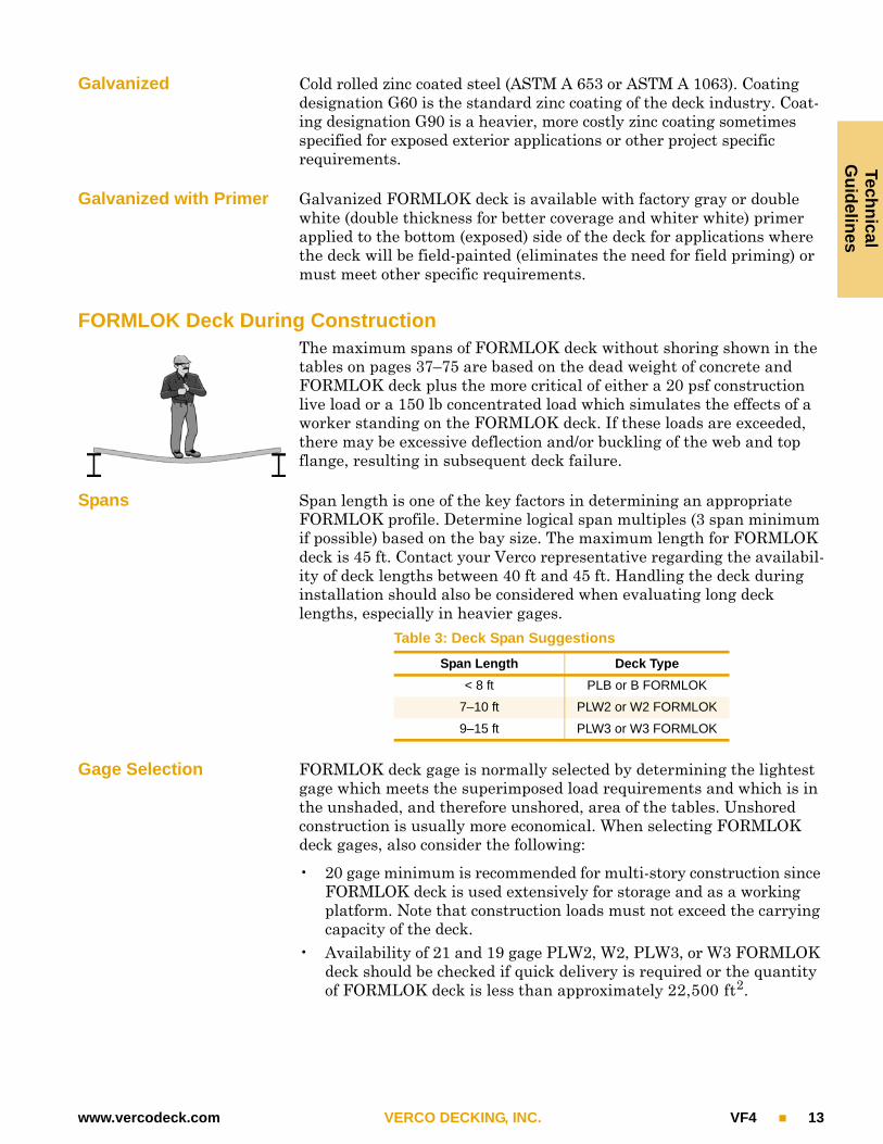
FORMLOK Deck During ConstructionThe maximum spans of FORMLOK deck without shoring shown in the tables on pages 37–75 are based on the dead weight of concrete and FORMLOK deck plus the more critical of either a 20 psf construction live load or a 150 lb concentrated load which simulates the effects of a worker standing on the FORMLOK deck. If these loads are exceeded, there may be excessive deflection and/or buckling of the web and top flange, resulting in subsequent deck failure.
Spans Span length is one of the key factors in determining an appropriate FORMLOK profile. Determine logical span multiples (3 span minimum if possible) based on the bay size. The maximum length for FORMLOK deck is 45 ft. Contact your Verco representative regarding the availabil-ity of deck lengths between 40 ft and 45 ft. Handling the deck during installation should also be considered when evaluating long deck lengths, especially in heavier gages.
Gage Selection FORMLOK deck gage is normally selected by determining the lightest gage which meets the superimposed load requirements and which is in the unshaded, and therefore unshored, area of the tables. Unshored construction is usually more economical. When selecting FORMLOK deck gages, also consider the following:
• 20 gage minimum is recommended for multi-story construction since FORMLOK deck is used extensively for storage and as a working platform. Note that construction loads must not exceed the carrying capacity of the deck.
• Availability of 21 and 19 gage PLW2, W2, PLW3, or W3 FORMLOK deck should be checked if quick delivery is required or the quantity of FORMLOK deck is less than approximately 22,500 ft2.
Table 3: Deck Span Suggestions
Span Length Deck Type
< 8 ft PLB or B FORMLOK
7–10 ft PLW2 or W2 FORMLOK
9–15 ft PLW3 or W3 FORMLOK

Tech
nic
al
Gu
idel
ines
14 VF4 VERCO DECKING, INC. www.vercodeck.com
Concrete Placement FORMLOK deck may be overloaded by the method used to place the concrete or by excessive deflection of beams or girders that are not shored or cambered. Place concrete first over beams and girders rather than at mid-span. Do not pile it higher than the finished depth of the slab. If overloading is anticipated, either select a heavier gage or shore FORMLOK deck during the pouring of concrete.
Note: Calcium chloride and concrete admixtures containing chloride salts shall not be used on FORMLOK deck.
Bearing Verco recommends 2 in. minimum bearing for FORMLOK deck. The required bearing should be verified based on specific project condi-tions. Adequate bearing is required to prevent web crippling of the deck during concrete placement and to allow for proper attachment of the deck. The allowable reactions shown in the tables are normally com-pared to the reactions due to dead load of the slab plus a 20 psf uniform construction live load. Allowable reactions are applicable to FORMLOK deck before the concrete has acquired minimum compressive strength. Adequate bearing at parallel supports should be provided to make the specified connections.
Note: The superimposed load tables on pages 37–75 assume allowable reactions that correspond to the maximum bearing length permit-ted (see AISI S100 for additional information). Project conditions where this assumption is no longer valid require further evalua-tion and may result in reduced maximum unshored clear spans.
Design Criteria for FORMLOK Deck-as-a-Form
The following design criteria and formulas were used to calculate the maximum spans of FORMLOK deck without shoring. Loading combina-tions utilized are illustrated in Figure 8 for clarity.
• wdl is the dead load of concrete plus deck plus deflection allowance.• The following allowances for FORMLOK deck deflection are
included in wdl:• 3 psf for light weight concrete,• 4 psf for normal weight concrete.
• No allowance is included for deflection of structural supports.• wll is 20 psf uniform construction live load.• P is 150 pound concentrated construction live load.• L is span length in feet. Span lengths shown in the tables are clear
spans.• ASD allowable moment, M = Mn / Ωb, where:
• Ωb = 1.67• Mn = Fy • Seff (+ or –), where:
• Fy = 50 ksi (all FORMLOK decks) = 60 ksi (all VERCOR decks)• Seff (+ or –) = Effective section modulus
• FORMLOK deck deflection is limited to the lesser of L/180 or ¾ in.• The tables assume allowable reactions based on the maximum bear-
ing length permitted by AISI S100. Specific project conditions may necessitate further evaluation.

Techn
icalG
uid
elines
www.vercodeck.com VERCO DECKING, INC. VF4 15
Design Formulas
+M = Positive Bending Moment in ft-lbM = Negative Bending Moment in ft-lb = Deflection in inches E = 29,500,000 psi Re = End reaction in lb/ft Ri = Interior reaction in lb/ft
Wdl
Wll
Single Span
Stress
Double Span
Stress
Triple Span
Stress
L/2L/2
wdl
L
P
L L
+Mwdl L2
8------------------ P L
4-----------+=
Deflection Deflection Deflection
0.013 wdl L4 1728
E I-------------------------------------------------------=
0.0054 wdl L4 1728 E I
-----------------------------------------------------------= 0.0069 wdl L4 1728
E I-----------------------------------------------------------=
Reactions Reactions Reactions
wll
Re 0.5 wdl wll+ L =Re 0.375 wdl wll+ L = Re 0.4 wdl wll+ L =
Ri 1.25 wdl wll+ L = Ri 1.1 wdl wll+ L =
M–wdl wII+ L2
8-----------------------------------= M– 0.117 wdl wII+ L2
=
wll
wdl
wll
L L L
wdlwdl
L L L
wdl
L L L
wdlwdl
L L L
wdl
L L L
wll
FIGURE 8
wll
wdl
wll
wdl
L L L L L
L/2P
L/2P
wdl wdl
L
+Mwdl wII+ L2
8-----------------------------------= +M 0.096 wdl L2 0.203 P L += +M 0.094 wdl L
2 0.2 P L +=
L L L L L
wll
wdl
+M 0.096 wdl wII+ L2
= +M 0.094 wdl wII+ L2
=
wll
wdl

Tech
nic
al
Gu
idel
ines
16 VF4 VERCO DECKING, INC. www.vercodeck.com
FORMLOK Composite Slab Design ExampleThis is a simple design example to illustrate the steps involved in the proper selection of FORMLOK deck. Various options are outlined for each point to be considered. This example illustrates the steps, not all possible selection options.
Design Goals The design goals for this example are as follows:
• Minimize dead load• Maximize slab stiffness• Eliminate temporary shoring
Span Options Spacing between beams determines the deck profile options. Refer to “Spans” on page 13 for more information.
Assume 6" wide framing members regardless of span used.
1. 15'-0" c-c span, 14'-6" clear span, 2 span condition.Choice: PLW3 (or W3) FORMLOK - may require shoring based on concrete type and thickness chosen.
2. 10'-0" c-c span, 9'-6" clear span, 3 span condition.Choices: PLW2 (or W2) FORMLOK or PLW3 (or W3) FORMLOK
3. 7'-6" c-c span, 7'-0" clear span, 4 span condition.Choices: PLB (or B) FORMLOK or PLW2 (or W2) FORMLOK
Concrete Type & Fire Rating Options
Use availability and relative cost of structural light weight (LW) versus normal weight (NW) concrete to determine the appropriate option. Refer to “Fire-Rated FORMLOK Composite Slabs” on page 8 and Table 9 on pages 30–31 for more information.
1. 4½" NW concrete over deck – without fireproofing.2. 3¼" LW concrete over deck – without fireproofing.3. 2½" concrete over deck (NW or LW) – with fireproofing.
Given: 30' x 30' bay size2-hour fire rated floor requiredUnderside of slab not exposed to viewLoads:
Live loadPartitionMechanical
100 psf20 psf
5 psf
Total Superimposed Load 125 psf
Select: Option 1 reduces the required framing, but may require shoring based on concrete selection. Options 2 and 3 offer reduced deck costs and eliminate any shoring requirements.
Select: Option 2 based on reduced weight and no fireproofing of deck required.

Techn
icalG
uid
elines
www.vercodeck.com VERCO DECKING, INC. VF4 17
FORMLOK Composite Slab Design Example (continued)
FORMLOK Deck Options Select FORMLOK profile and gage such that shoring is not required. Verify that adequate bearing is provided.
FORMLOK Finish Options
Options are listed in order of increasing cost. Based on a typical installation with the deck exposed only to an interior environment, phosphatized/painted deck offers the most economical FORMLOK option. Phosphatized/painted deck may also yield labor savings due to easier stud shear connector welding.
Refer to “FORMLOK Deck Finishes” on page 12 for more information.
1. Phosphatized top side/Painted bottom (exposed) side.2. Galvanized.3. Galvanized and painted underside.
Specific Considerations Determine whether factory-punched vent tabs should be specified in the FORMLOK deck. Specify attachment of the FORMLOK deck to supports as necessary to meet diaphragm requirements.
Refer to “Venting FORMLOK Deck” on page 9 and “Attachment of FORMLOK Deck” on page 10.
OptionClear Span
FORMLOK Deck
Profile
LW Concrete Total Slab
Depth(in.)
Shoring Required?
Allowable Super-
imposed Load(psf)
Total Slab
Weight1
(psf)
Span to Total Slab
Depth Ratio
FORMLOK Deck Bearing
End2"
Interior6"
1 14'-6" PLW3-18 ga 6¼ NO 170 49.4 28 OK OK
2 9'-6" PLW2-20 ga 5¼ NO 258 44.1 22 OK OK
3 9'-6" PLW3-20 ga 6¼ NO 275 48.8 18 OK OK
4 7'-0" PLB-22 ga 4¾ NO 301 39.6 18 OK OK
1 Total slab weight = concrete + deck deflection allowance + FORMLOK deck (galvanized deck assumed).
Select: Selection should be based on framing layout. Option 1 minimizes the number of framing members, but may require investigation into slab stiffness and project serviceability requirements. Choose between Options 2 and 3 based on assembly weight vs. slab stiffness. Utilizing the PunchLok® system with any choice gives the optimal combination of strength and installed cost.
Select: Option 1 due to lowest cost and appropriateness for assumed interior environment.

Tech
nic
alG
uid
elin
es
18 VF4 VERCO DECKING, INC. www.vercodeck.com
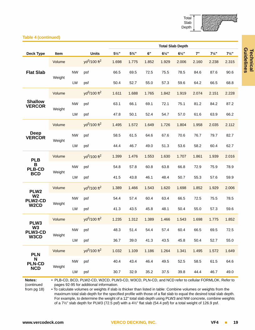
Concrete Volumes and WeightsTable 4
Deck Type Item Units
Total Slab Depth
2½" 3" 3½" 4" 4½" 4¾" 5" 5¼"
Flat Slab
Volume yd3/100 ft2 0.772 0.926 1.080 1.235 1.389 1.466 1.543 1.620
Weight
NW psf 30.2 36.3 42.3 48.3 54.4 57.4 60.4 63.4
LW psf 22.9 27.5 32.1 36.7 41.3 43.5 45.8 48.1
Shallow VERCOR
Volume yd3/100 ft2 0.685 0.839 0.993 1.148 1.302 1.379 1.456 1.534
Weight
NW psf 26.8 32.9 38.9 44.9 51.0 54.0 57.0 60.0
LW psf 20.3 24.9 29.5 34.1 38.7 41.0 43.3 45.5
Deep VERCOR
Volume yd3/100 ft2 0.878 1.032 1.186 1.264 1.341 1.418
Weight
NW psf 34.4 40.4 46.4 49.5 52.5 55.5
LW psf 26.1 30.7 35.2 37.5 39.8 42.1
PLBB
PLB-CDBCD
Volume yd3/100 ft2 0.781 0.936 1.090 1.167 1.244 1.321
Weight
NW psf 30.6 36.6 42.7 45.7 48.7 51.7
LW psf 23.2 27.8 32.4 34.7 37.0 39.2
PLW2W2
PLW2-CDW2CD
Volume yd3/100 ft2 0.926 1.080 1.157 1.235 1.312
Weight
NW psf 36.3 42.3 45.3 48.3 51.4
LW psf 27.5 32.1 34.4 36.7 39.0
PLW3W3
PLW3-CDW3CD
Volume yd3/100 ft2 1.080 1.157
Weight
NW psf 42.3 45.3
LW psf 32.1 34.4
PLNN
PLN-CDNCD
Volume yd3/100 ft2 0.878 0.955
Weight
NW psf 34.4 37.4
LW psf 26.1 28.4
Notes:(continued next page)
• Volumes and weights do not include allowance for deflection.• Weights are for concrete only and do not include weight of steel deck.• Volume in table is cubic yards per 100 square feet.• Weight given is pounds per square foot.
TotalSlab
Depth
Techn
icalG
uid
elines
www.vercodeck.com VERCO DECKING, INC. VF4 19
Table 4 (continued)
Deck Type Item Units
Total Slab Depth
5½" 5¾" 6" 6¼" 6½" 7" 7¼" 7½"
Flat Slab
Volume yd3/100 ft2 1.698 1.775 1.852 1.929 2.006 2.160 2.238 2.315
Weight
NW psf 66.5 69.5 72.5 75.5 78.5 84.6 87.6 90.6
LW psf 50.4 52.7 55.0 57.3 59.6 64.2 66.5 68.8
Shallow VERCOR
Volume yd3/100 ft2 1.611 1.688 1.765 1.842 1.919 2.074 2.151 2.228
Weight
NW psf 63.1 66.1 69.1 72.1 75.1 81.2 84.2 87.2
LW psf 47.8 50.1 52.4 54.7 57.0 61.6 63.9 66.2
Deep VERCOR
Volume yd3/100 ft2 1.495 1.572 1.649 1.726 1.804 1.958 2.035 2.112
Weight
NW psf 58.5 61.5 64.6 67.6 70.6 76.7 79.7 82.7
LW psf 44.4 46.7 49.0 51.3 53.6 58.2 60.4 62.7
PLBB
PLB-CDBCD
Volume yd3/100 ft2 1.399 1.476 1.553 1.630 1.707 1.861 1.939 2.016
Weight
NW psf 54.8 57.8 60.8 63.8 66.8 72.9 75.9 78.9
LW psf 41.5 43.8 46.1 48.4 50.7 55.3 57.6 59.9
PLW2W2
PLW2-CDW2CD
Volume yd3/100 ft2 1.389 1.466 1.543 1.620 1.698 1.852 1.929 2.006
Weight
NW psf 54.4 57.4 60.4 63.4 66.5 72.5 75.5 78.5
LW psf 41.3 43.5 45.8 48.1 50.4 55.0 57.3 59.6
PLW3W3
PLW3-CDW3CD
Volume yd3/100 ft2 1.235 1.312 1.389 1.466 1.543 1.698 1.775 1.852
Weight
NW psf 48.3 51.4 54.4 57.4 60.4 66.5 69.5 72.5
LW psf 36.7 39.0 41.3 43.5 45.8 50.4 52.7 55.0
PLNN
PLN-CDNCD
Volume yd3/100 ft2 1.032 1.109 1.186 1.264 1.341 1.495 1.572 1.649
Weight
NW psf 40.4 43.4 46.4 49.5 52.5 58.5 61.5 64.6
LW psf 30.7 32.9 35.2 37.5 39.8 44.4 46.7 49.0
Notes:(continued from pg 18)
• PLB-CD, BCD, PLW2-CD, W2CD, PLW3-CD, W3CD, PLN-CD, and NCD refer to cellular FORMLOK. Refer to pages 92-95 for additional information.
• To calculate volumes or weights if slab is thicker than listed in table: Combine volumes or weights from the maximum total slab depth for the specified profile with those of a flat slab to equal the desired total slab depth. For example, to determine the weight of a 12" total slab depth using PLW3 and NW concrete, combine weights of a 7½" slab depth for PLW3 (72.5 psf) with a 4½" flat slab (54.4 psf) for a total weight of 126.9 psf.
TotalSlab
Depth
Tech
nic
alG
uid
elin
es
20 VF4 VERCO DECKING, INC. www.vercodeck.com
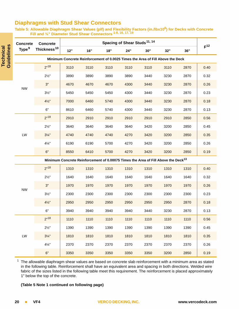
Diaphragms with Stud Shear ConnectorsTable 5: Allowable Diaphragm Shear Values (plf) and Flexibility Factors (in./lbx106) for Decks with Concrete
Fill and ¾" Diameter Stud Shear Connectors 1-8, 16, 17, 19
Concrete
Type9Concrete
Thickness10
Spacing of Shear Studs11, 14
F12
12" 16" 18" 24" 30" 32" 36"
Minimum Concrete Reinforcement of 0.0025 Times the Area of Fill Above the Deck
NW
2"18 3110 3110 3110 3110 3110 3110 2870 0.40
2½" 3890 3890 3890 3890 3440 3230 2870 0.32
3" 4670 4670 4670 4300 3440 3230 2870 0.26
3½" 5450 5450 5450 4300 3440 3230 2870 0.23
4½" 7000 6460 5740 4300 3440 3230 2870 0.18
6" 8610 6460 5740 4300 3440 3230 2870 0.13
LW
2"18 2910 2910 2910 2910 2910 2910 2850 0.56
2½" 3640 3640 3640 3640 3420 3200 2850 0.45
3¼" 4740 4740 4740 4270 3420 3200 2850 0.35
4¼" 6190 6190 5700 4270 3420 3200 2850 0.26
6" 8550 6410 5700 4270 3420 3200 2850 0.19
Minimum Concrete Reinforcement of 0.00075 Times the Area of Fill Above the Deck13
NW
2"18 1310 1310 1310 1310 1310 1310 1310 0.40
2½" 1640 1640 1640 1640 1640 1640 1640 0.32
3" 1970 1970 1970 1970 1970 1970 1970 0.26
3½" 2300 2300 2300 2300 2300 2300 2300 0.23
4½" 2950 2950 2950 2950 2950 2950 2870 0.18
6" 3940 3940 3940 3940 3440 3230 2870 0.13
LW
2"18 1110 1110 1110 1110 1110 1110 1110 0.56
2½" 1390 1390 1390 1390 1390 1390 1390 0.45
3¼" 1810 1810 1810 1810 1810 1810 1810 0.35
4¼" 2370 2370 2370 2370 2370 2370 2370 0.26
6" 3350 3350 3350 3350 3350 3200 2850 0.19
1 The allowable diaphragm shear values are based on concrete slab reinforcement with a minimum area as stated in the following table. Reinforcement shall have an equivalent area and spacing in both directions. Welded wire fabric of the sizes listed in the following table meet this requirement. The reinforcement is placed approximately 1" below the top of the concrete.
(Table 5 Note 1 continued on following page)

Techn
icalG
uid
elines
www.vercodeck.com VERCO DECKING, INC. VF4 21
Table 5 Note 1 (continued from preceding page)Minimum Reinforcement for Tabulated Shear Values
Concrete Thickness10
Reinforcement = 0.0025 Times Area of Fill Above the Deck
Reinforcement = 0.00075 Times Area of Fill Above the Deck
Area of Steel (in.2/ft) Suggested Fabric15 Area of Steel (in.2/ft) Suggested Fabric15
2" 0.060 4 x 4 - W2.0 x W2.0 0.028 6 x 6 - W1.4 x W1.4
2½" 0.075 4 x 4 - W2.5 x W2.5 0.028 6 x 6 - W1.4 x W1.4
3" 0.090 6 x 6 - W4.5 x W4.5 0.028 6 x 6 - W1.4 x W1.4
3¼" 0.098 6 x 6 - W5.0 x W5.0 0.029 6 x 6 - W2.0 x W2.0
3½" 0.105 4 x 4 - W3.5 x W3.5 0.032 6 x 6 - W2.0 x W2.0
4¼" 0.128 6 x 6 - W6.5 x W6.5 0.038 6 x 6 - W2.0 x W2.0
4½" 0.135 4 x 4 - W4.5 x W4.5 0.041 4 x 4 - W1.4 x W1.4
6" 0.180 4 x 4 - W6.0 x W6.0 0.054 6 x 6 - W2.9 x W2.9
2 Stud shear connector diameter must be less than or equal to 2.5 times the steel support thickness unless connec-tor is located directly over the support web.
3 See Figure 9 for details.4 Allowable diaphragm shear strengths assume “weak stud position” as shown in Figure 10 with a single shear stud
per rib at the spacing shown in the tables. The allowable values may be used when the deck is either perpendicu-lar or parallel to the supports.
5 For local shear transfer within the field of the diaphragm, ¾" diaphragm shear stud connectors having an allow-able shear value of 8.60 kips per stud for normal weight concrete fills and 8.55 kips per stud for structural light weight concrete shall be used. However, when using Deep VERCOR, ½" diameter studs having an allowable shear value of 3.83 kips per stud for normal weight concrete and 3.80 kips per stud for light weight concrete shall be used.
6 Sidelap connections shall be spaced at 36" on center maximum with either button punch, No. 10 screw, 1½" long top seam weld (standing seams), or 1½" long fillet weld (nested seams). Sidelaps of PLB, PLW2, PLW3, and PLN shall be connected with Verco Sidelap Connections (VSC) at 36" on center maximum.
7 To obtain factored (LRFD) diaphragm strengths, the values may be multiplied by a factor of 1.5 for all load combi-nations.
8 See ACI 318, Section 9.3.4 for possible reductions of the diaphragm shear capacity dependent on the vertical components of the primary lateral-force-resisting system. Tabulated values may be multiplied by /0.75, where is modified in accordance with ACI 318, Section 9.3.4.
9 Design compressive strength f 'c = 3000 psi minimum.NW = Normal weight concrete (145 pcf); LW = Structural light weight concrete (110 pcf).
10 Concrete thickness (t f) is measured above top flute of steel deck.11 FORMLOK deck types PLB, B, PLBCD, BCD, BR, PLW2, W2, PLW2CD, W2CD, PLW3, W3, PLW3CD, W3CD,
PLN, N, PLNCD, and NCD shall use a minimum ¾" diameter stud shear connectors to achieve the allowable val-ues. Deep VERCOR (15-qy" deep) shall use ½" diameter stud shear connectors. The tabulated values shall be mul-tiplied by a factor of 0.44 for Deep VERCOR.
12 The flexibility factor (F) is the number of microinches a diaphragm web will deflect in a span of 1 foot under a shear load of 1 pound per foot.
13 Also compare to the allowable diaphragm capacity for FORMLOK decks with concrete thicknesses shown on pages 37–75.
(Notes continued on following page)

Tech
nic
alG
uid
elin
es
22 VF4 VERCO DECKING, INC. www.vercodeck.com
(Table 5 Notes continued from preceding page)
14 The maximum center-to-center spacing of stud shear connectors shall not exceed either 8 times the total slab thickness or 36".
15 Minimum lap of welded wire fabric shall be 12".16 Steel decks shall be fastened to intermediate deck supports with arc spot welds or mechanical fasteners.17
Stud shear connectors shall extend not less than 1½" above top of steel deck and shall have at least ½" concrete cover. Minimum stud lengths for each deck profile are given in Figure 9.
18 Tabulated shear values for slabs with 2" concrete cover thickness are not applicable to Deep VERCOR deck unless stud shear connectors meeting the requirements of footnote 17 are used.
19 All FORMLOK and Deep VERCOR steel deck profiles have an average rib width, wr, of not less than 2" as required in AISC Specification Section I3.2.
l s l s
t f
t d
t f
t d
Stud shear connectors to supports parallel to flutes. Size and spacing per Table 5.
Stud shear connectorsto supports perpendicu-
lar to flutes. Size andspacing per Table 5.
Stud Shear Connectors at Supports Parallel to Flutes
Stud Shear Connectors at Supports Perpendicular to Flutes
Typical Exterior or Interior Shear Transfer Studs
Deck Height(td)
Stud Length*(ls)
15-qy" 3"
1½" 3"
2" 3½"
3" 4½"
* Minimum finished length
FIGURE 9
Mesh Mesh
FIGURE 10
Stud Shear Connector
Techn
icalG
uid
elines
www.vercodeck.com VERCO DECKING, INC. VF4 23
Stud Shear Connectors
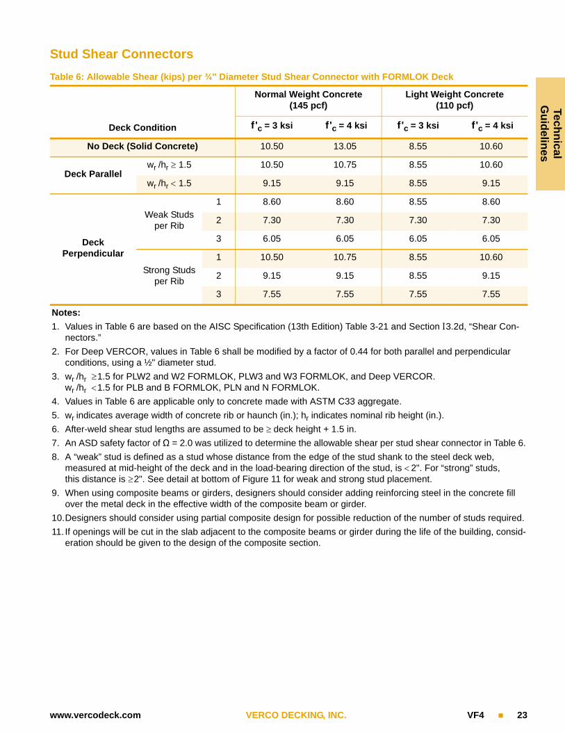
Table 6: Allowable Shear (kips) per ¾" Diameter Stud Shear Connector with FORMLOK Deck
Deck Condition
Normal Weight Concrete (145 pcf)
Light Weight Concrete(110 pcf)
f 'c = 3 ksi f 'c = 4 ksi f 'c = 3 ksi f 'c = 4 ksi
No Deck (Solid Concrete) 10.50 13.05 8.55 10.60
Deck Parallelwr /hr 1.5 10.50 10.75 8.55 10.60
wr /hr 1.5 9.15 9.15 8.55 9.15
DeckPerpendicular
Weak Studs per Rib
1 8.60 8.60 8.55 8.60
2 7.30 7.30 7.30 7.30
3 6.05 6.05 6.05 6.05
Strong Studs per Rib
1 10.50 10.75 8.55 10.60
2 9.15 9.15 8.55 9.15
3 7.55 7.55 7.55 7.55
Notes:
1. Values in Table 6 are based on the AISC Specification (13th Edition) Table 3-21 and Section I3.2d, “Shear Con-nectors.”
2. For Deep VERCOR, values in Table 6 shall be modified by a factor of 0.44 for both parallel and perpendicular conditions, using a ½" diameter stud.
3. wr /hr 1.5 for PLW2 and W2 FORMLOK, PLW3 and W3 FORMLOK, and Deep VERCOR.wr /hr 1.5 for PLB and B FORMLOK, PLN and N FORMLOK.
4. Values in Table 6 are applicable only to concrete made with ASTM C33 aggregate.
5. wr indicates average width of concrete rib or haunch (in.); hr indicates nominal rib height (in.).
6. After-weld shear stud lengths are assumed to be deck height + 1.5 in.
7. An ASD safety factor of Ω = 2.0 was utilized to determine the allowable shear per stud shear connector in Table 6.
8. A “weak” stud is defined as a stud whose distance from the edge of the stud shank to the steel deck web, measured at mid-height of the deck and in the load-bearing direction of the stud, is 2". For “strong” studs, this distance is 2". See detail at bottom of Figure 11 for weak and strong stud placement.
9. When using composite beams or girders, designers should consider adding reinforcing steel in the concrete fill over the metal deck in the effective width of the composite beam or girder.
10.Designers should consider using partial composite design for possible reduction of the number of studs required.
11. If openings will be cut in the slab adjacent to the composite beams or girder during the life of the building, consid-eration should be given to the design of the composite section.

Tech
nic
alG
uid
elin
es
24 VF4 VERCO DECKING, INC. www.vercodeck.com
Stud Shear Connector Placement and Details
2"
Bottom ofFORMLOK
Flute
3" Minimum
5-qy" FlangeThickness (Minimum)
7-i" Minimum
Bottom ofFORMLOK
Flute
Bottom ofFORMLOK
Flute 3 Studs per Flute(PLW2, W2, PLW3, and W3 FORMLOK)
5-qy" Flange Thickness (Minimum)
3" Minimum
3" Minimum
3" Minimum
Suggested ¾" Diameter Stud Placement and Minimum Flange Widths
2 Studs per Flute(PLB and B FORMLOK)
1 Stud per Flute(PLB and B FORMLOK)
1 or 2 Studs per Flute(PLW2, W2, PLW3, and W3 FORMLOK)
FIGURE 11
All Deck Profiles
Minimum Rib Widths for Full Value of Stud
2 Rows of Studs
41-w" Minimum
FORMLOK Deck Parallel to Girder
3" Minimum
1 Row of Studs
7-i" Minimum
Note: Tables 5 and 6 assume weak stud placement.
Direction of Shear
Strong Stud/Weak Stud Placement
7-i" Minimum

Techn
icalG
uid
elines
www.vercodeck.com VERCO DECKING, INC. VF4 25
FORMLOK Composite Slab–Suggested Details
FIGURE 12
Edge Conditions Interior Conditions
Edge Form
End Closure
Cantilever Parallel
Parallel Parallel with Filler Plates
Edge Form
Girder Filler
Perpendicular Change of Deck Direction
Edge FormEnd Closure End Closure
Tech
nic
alG
uid
elin
es
26 VF4 VERCO DECKING, INC. www.vercodeck.com
Edge Form Suggestions
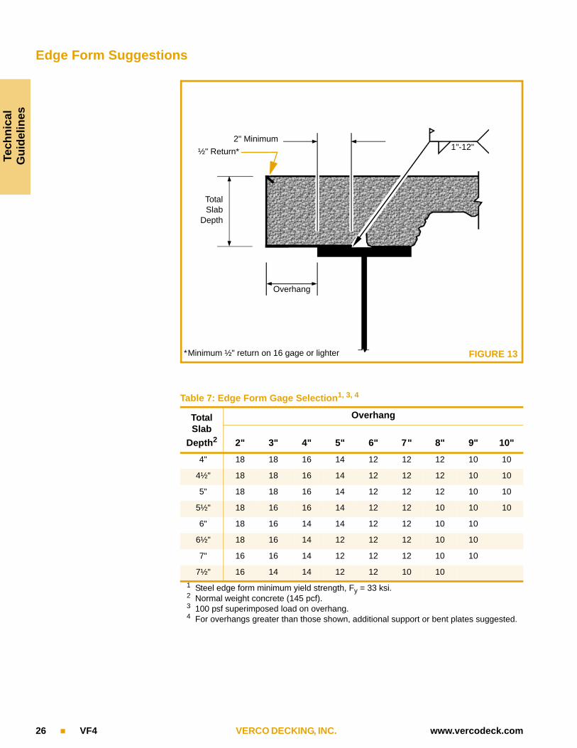
Table 7: Edge Form Gage Selection1, 3, 4
Total
Slab
Depth2
Overhang
2" 3" 4" 5" 6" 7" 8" 9" 10"
4" 18 18 16 14 12 12 12 10 10
4½" 18 18 16 14 12 12 12 10 10
5" 18 18 16 14 12 12 12 10 10
5½" 18 16 16 14 12 12 10 10 10
6" 18 16 14 14 12 12 10 10
6½" 18 16 14 12 12 12 10 10
7" 16 16 14 12 12 12 10 10
7½" 16 14 14 12 12 10 10
1 Steel edge form minimum yield strength, Fy = 33 ksi.2 Normal weight concrete (145 pcf).3 100 psf superimposed load on overhang.4 For overhangs greater than those shown, additional support or bent plates suggested.
FIGURE 13
2" Minimum
TotalSlab
Depth
Overhang
1"-12" ½" Return*
*Minimum ½" return on 16 gage or lighter

Techn
icalG
uid
elines
www.vercodeck.com VERCO DECKING, INC. VF4 27
Floor Deck Accessories
Profile Closures Profile closures made from steel or neoprene are designed to fit Verco’s FORMLOK and VERCOR deck products. See Table 8 for availability of closures by deck profile. Steel closures are 22 gage with a 1 in. return lip for fastening to deck with screws or tack welds. Neoprene closures for FORMLOK decks are 1 in. thick individual plugs. Neoprene closures for VERCOR decks are 1 in. thick, 36 in. long strips. See Figure 14.
33
Weld Washers Welding VERCOR decks lighter than 22 gage requires weld washers in accordance with AWS D1.3. Weld washers are not required or recommended for arc spot welds in FORMLOK decks. See Figure 15.
End Closures 20 gage steel end closures are available for all FORMLOK profiles. See Figure 16 for available sizes and Figure 12 for suggested details.
Table 8: Availability of Profile Closures
Deck ProfileSteel Closures Neoprene Closures
Underside Topside Underside Topside
PLB or B FORMLOK
PLW2 or W2 FORMLOK
PLW3 or W3 FORMLOK
PLN or N FORMLOK
Deep VERCOR
Shallow VERCOR
FIGURE 14
Underside Steel Profile Closure
Topside Steel Profile Closure
Topside Neoprene Closure
Underside Neoprene Closure
Topside Neoprene Closure – Sidelap
Note: PLB or B FORMLOK deck and closures shown; closures for other profiles are installed similarly.
FIGURE 15
Arc spot weld through 3-i" dia. hole in weld washer
FIGURE 16
1½''
1½''1½''
1½''
3''2''
Note: Available only in 10 ft lengths.
Tech
nic
alG
uid
elin
es
28 VF4 VERCO DECKING, INC. www.vercodeck.com
Openings in FORMLOK Decks
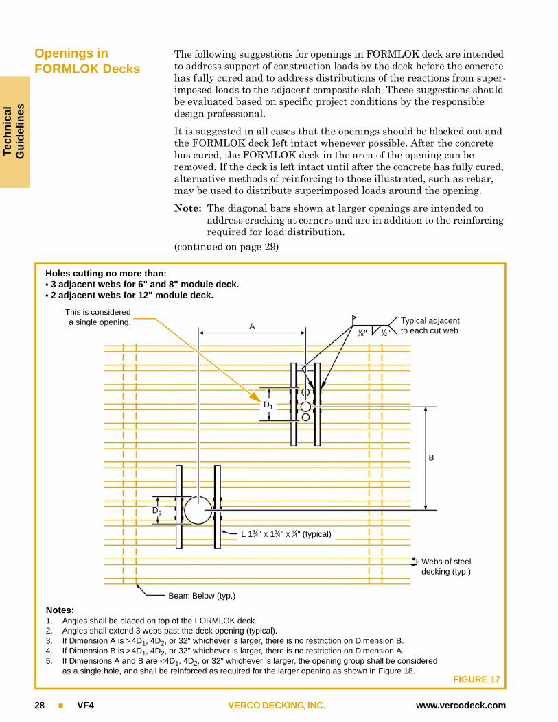
The following suggestions for openings in FORMLOK deck are intended to address support of construction loads by the deck before the concrete has fully cured and to address distributions of the reactions from super-imposed loads to the adjacent composite slab. These suggestions should be evaluated based on specific project conditions by the responsible design professional.
It is suggested in all cases that the openings should be blocked out and the FORMLOK deck left intact whenever possible. After the concrete has cured, the FORMLOK deck in the area of the opening can be removed. If the deck is left intact until after the concrete has fully cured, alternative methods of reinforcing to those illustrated, such as rebar, may be used to distribute superimposed loads around the opening.
Note: The diagonal bars shown at larger openings are intended to address cracking at corners and are in addition to the reinforcing required for load distribution.
(continued on page 29)
Notes:1. Angles shall be placed on top of the FORMLOK deck.2. Angles shall extend 3 webs past the deck opening (typical).3. If Dimension A is >4D1, 4D2, or 32" whichever is larger, there is no restriction on Dimension B.4. If Dimension B is >4D1, 4D2, or 32" whichever is larger, there is no restriction on Dimension A.5. If Dimensions A and B are <4D1, 4D2, or 32" whichever is larger, the opening group shall be considered
as a single hole, and shall be reinforced as required for the larger opening as shown in Figure 18.FIGURE 17
This is considereda single opening.
1-i" 1-w"
Typical adjacentto each cut web
D1
B
Beam Below (typ.)
A
D2
L 13-r" x 13-r" x 1-r" (typical)
Holes cutting no more than:• 3 adjacent webs for 6" and 8" module deck.• 2 adjacent webs for 12" module deck.
Webs of steel decking (typ.)

Techn
ical
Gu
idelin
es
www.vercodeck.com VERCO DECKING, INC. VF4 29
(continued from page 28) • Typically, individual holes less than 6 in. in diameter and cutting no more than one web need no reinforcing.
• Figure 17 illustrates recommendations for holes 6 in. in diameter, those cutting more than one web, or groups of small holes.
• Figure 18 illustrates recommendations for larger openings.• Header beams should be placed around openings or groups of open-
ings larger than 24 in.The critical dimension for an opening or groups of openings is the width measured perpendicular to the deck span as shown in Figures 17 and 18. The length of an opening or hole measured parallel to the direction of the deck span is not limited.
FIGURE 18
Notes:1. Tubes shall be placed on top of the deck. Note: Availability may suggest the use of alternate members such as
channels or angles with comparable strength.2. Add rebars at corners of opening above the tubes.3. If the opening or group of openings occurs in one FORMLOK deck unit, the opening or opening group may be
cut before pouring concrete.4. If the opening or group of openings cuts through two FORMLOK deck units, the deck shall not be cut until
concrete has been placed and cured. At the time of pouring, suitable sleeves or bulkheads shall be placed around the opening.
5. When the maximum dimension of an opening or opening group exceeds 24", place header beams around opening.
1-i"11-w" Min 1"
3 F
lute
s
At center of each upper flute beyond opening (typical)
Webs of steel decking (typ.)
3 F
lute
s
Beam Below (typ.)
1-i" 1-w"
24"
Ma
x Rebar
11-w" x 3" x 1-i" Steel Tubes
Adjacent to each cut web (typical)
(typical)
Larger holes, rectangular or square

Tech
nic
alG
uid
elin
es
30 VF4 VERCO DECKING, INC. www.vercodeck.com
FORMLOK Composite Slab Fire Resistance RatingsTable 9 2, 4, 6, 8, 9
RESTRAINED ASSEMBLY RATING (hr)
UL # FRAME CONCRETE (in.)7 FORMLOK DECK1 PROTECTED5
B BR W2 W3 N
1-4 D739 Beam/Joist 2½" LW, NW SFRM
1-3 D743 Beam 2" LW, NW SFRM
2 D750 Beam 2½" LW, NW SFRM
2-3 D755 Beam/Joist 2½" LW, NW SFRM
2-3 D759 Beam/Joist 2½" LW, NW SFRM
2-4 D760 Beam/Joist 2½" LW, NW SFRM
2 D764 Beam/Joist 2½" LW, NW SFRM
1-4 D767 Beam/Joist 2½" LW, NW SFRM
2 D775 Beam 2½" LW, NW SFRM
1-4 D779 Beam/Joist 2½" LW, NW SFRM
1-4 D787 Beam/Joist 2½" LW, NW SFRM
1-4 D788 Beam/Joist 2½" LW, NW SFRM
2 D794 Beam/Joist 2½" LW, NW SFRM
1-3 D795 Beam/Joist 2½" LW, NW SFRM
1-4 D796 Beam/Joist 2½" LW, NW SFRM
2 D826 Beam 3¼" LW SFRM
2-3 D832 Beam 2½" LW, NW SFRM
2 D840 Beam (varies) LW SFRM
1-4 D858 Beam 2½" LW, NW SFRM
1-3 D859 Beam 2" LW, NW SFRM
3 D867 Beam 2½" LW, NW SFRM
1-3 D871 Beam 2½" LW, NW SFRM
1-3 D875 Beam 2" LW, NW SFRM
2 D878 Beam 3¼" LW SFRM
1-3 D883 Beam 2½" LW, NW SFRM
2 D888 Beam (varies) LW SFRM
1-4 D891 Beam 2½" LW, NW SFRM
3 D896 Beam (varies) LW, NW SFRM
1-3 D898 Beam 2½" LW, NW SFRM
1-3 D902 Beam/Joist (varies) LW, NW 3 3 3 3 No
2 D907 Beam 3¼" LW No
¾-1 D914 Beam 2½" LW No
¾-3 D916 Beam/Joist (varies) LW, NW No
(continued on following page)

Tech
nical
Gu
idelin
es
www.vercodeck.com VERCO DECKING, INC. VF4 31
Table 9 (continued)
1 “B” = PLB and B FORMLOK “W2” = PLW2 and W2 FORMLOK“N” = PLN and N FORMLOK “W3” = PLW3 and W3 FORMLOK
2 Refer to UL Fire Resistance Directory, evaluation reports for Verco Steel Deck, or municipality requirements for full details of construction including concrete thickness and strength requirements, and span limitations.
3 Denotes that the FORMLOK deck profile may be fluted or cellular. 4 Code-compliant Verco gray primer paint is formulated for compatibility with spray-applied fireproofing. Verco steel decks in the assemblies
listed above may be galvanized or painted, excluding assemblies D924, D969, D973, and D974, which shall be galvanized only. 5 Protected assemblies have spray-applied fireproofing applied directly to the underside of the deck. Unprotected assemblies do not require
spray-applied fireproofing applied to the underside of the deck. “SFRM = Spray-Applied Fire Resistive Materials.” 6 Verco Decking, Inc. assumes no responsibility for adhesion of any spray-applied fireproofing material, nor for any treatment, cleaning, or sur-
face preparation of the deck required for adhesion of fire protection material. 7 Concrete thickness is measured from top of deck to top of slab. 8 All assemblies except D750, D760, D775, D779, and D924 are permitted to be blended. Blended deck refers to the allowed combination of
cellular and non-cellular deck for the floor system. 9 Sidelap fastening by either button punch, seam weld, or VSC is required. Minimum ¾" long #10 self-drilling screws may be substituted for but-
ton punches at the spacing indicated for button punches.
RESTRAINED ASSEMBLY RATING (hr)
UL # FRAME CONCRETE (in.)7 FORMLOK DECK1 PROTECTED5
B BR W2 W3 N
1-3 D919 Beam (varies) LW, NW No
2 D920 Beam 3¼" LW No
¾-3 D922 Beam/Joist (varies) LW, NW No
¾-3 D923 Beam (varies) LW, NW No
2-3 D924 Beam (varies) LW, NW No
¾-3 D925 Beam/Joist (varies) LW, NW No
¾-3 D927 Beam/Joist (varies) LW, NW No
1-3 D929 Beam (varies) LW, NW No
2 D931 Beam (varies) LW, NW No
1-3 D943 Beam/Joist (varies) LW, NW No
1-3 D949 Beam/Joist (varies) LW, NW No
1-3 D957 Beam/Joist (varies) LW, NW 3 3 3 3 No
¾-3 D958 Beam/Joist (varies) LW, NW 3 3 3 3 No
¾-1 D967 Beam 2½" LW 3 3 3 3 No
1-3 D968 Beam (varies) LW, NW 3 No
2-3 D969 Beam (varies) LW, NW No
2 D973 Beam 3¾" NW No
3 D974 Beam/Joist 4½" NW 3 3 3 3 No
1-3 D975 Beam (varies) LW, NW 3 3 3 3 No
Tech
nic
alG
uid
elin
es
32 VF4 VERCO DECKING, INC. www.vercodeck.com
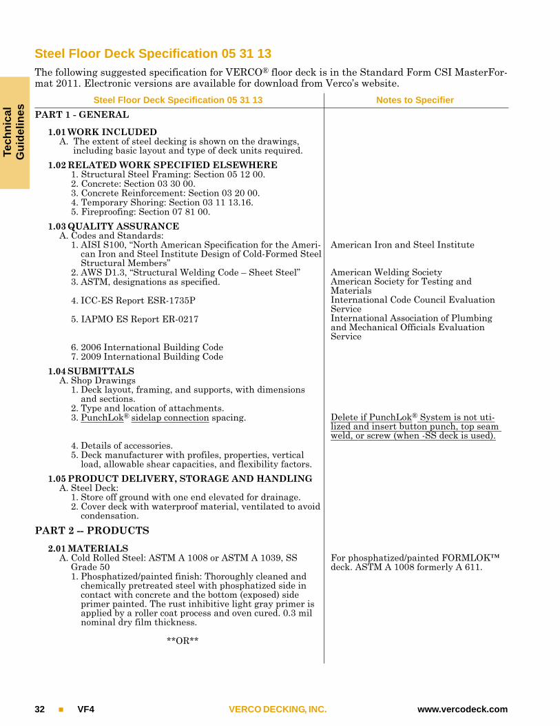
Steel Floor Deck Specification 05 31 13The following suggested specification for VERCO® floor deck is in the Standard Form CSI MasterFor-mat 2011. Electronic versions are available for download from Verco’s website.
Steel Floor Deck Specification 05 31 13 Notes to Specifier
PART 1 - GENERAL
1.01 WORK INCLUDEDA. The extent of steel decking is shown on the drawings,
including basic layout and type of deck units required.
1.02 RELATED WORK SPECIFIED ELSEWHERE1. Structural Steel Framing: Section 05 12 00.2. Concrete: Section 03 30 00.3. Concrete Reinforcement: Section 03 20 00.4. Temporary Shoring: Section 03 11 13.16.5. Fireproofing: Section 07 81 00.
1.03 QUALITY ASSURANCEA. Codes and Standards:
1. AISI S100, “North American Specification for the Ameri-can Iron and Steel Institute Design of Cold-Formed Steel Structural Members”
2. AWS D1.3, “Structural Welding Code – Sheet Steel”3. ASTM, designations as specified.
4. ICC-ES Report ESR-1735P
5. IAPMO ES Report ER-0217
6. 2006 International Building Code7. 2009 International Building Code
American Iron and Steel Institute
American Welding SocietyAmerican Society for Testing and MaterialsInternational Code Council Evaluation ServiceInternational Association of Plumbing and Mechanical Officials Evaluation Service
1.04 SUBMITTALSA. Shop Drawings
1. Deck layout, framing, and supports, with dimensions and sections.
2. Type and location of attachments.3. PunchLok® sidelap connection spacing.
4. Details of accessories.5. Deck manufacturer with profiles, properties, vertical
load, allowable shear capacities, and flexibility factors.
Delete if PunchLok® System is not uti-lized and insert button punch, top seam weld, or screw (when -SS deck is used).
1.05 PRODUCT DELIVERY, STORAGE AND HANDLINGA. Steel Deck:
1. Store off ground with one end elevated for drainage.2. Cover deck with waterproof material, ventilated to avoid
condensation.
PART 2 -- PRODUCTS
2.01 MATERIALSA. Cold Rolled Steel: ASTM A 1008 or ASTM A 1039, SS
Grade 50 1. Phosphatized/painted finish: Thoroughly cleaned and
chemically pretreated steel with phosphatized side in contact with concrete and the bottom (exposed) side primer painted. The rust inhibitive light gray primer is applied by a roller coat process and oven cured. 0.3 mil nominal dry film thickness.
**OR**
For phosphatized/painted FORMLOK™ deck. ASTM A 1008 formerly A 611.
Tech
nical
Gu
idelin
es
www.vercodeck.com VERCO DECKING, INC. VF4 33
A. Galvanized Steel: ASTM A 653 or ASTM A 1063, SS Grade 501. Zinc coated per ASTM A 653 or ASTM A 1063, G60
**OR**A. Galvanized Steel: ASTM A 653 or ASTM A 1063, SS
Grade 801. Zinc coated per ASTM A 653 or ASTM A 1063, G90
For galvanized FORMLOK™ deck. ASTM A 653 formerly A 446.
For Deep or Shallow VERCOR™ deck.ASTM A 653 formerly A 446
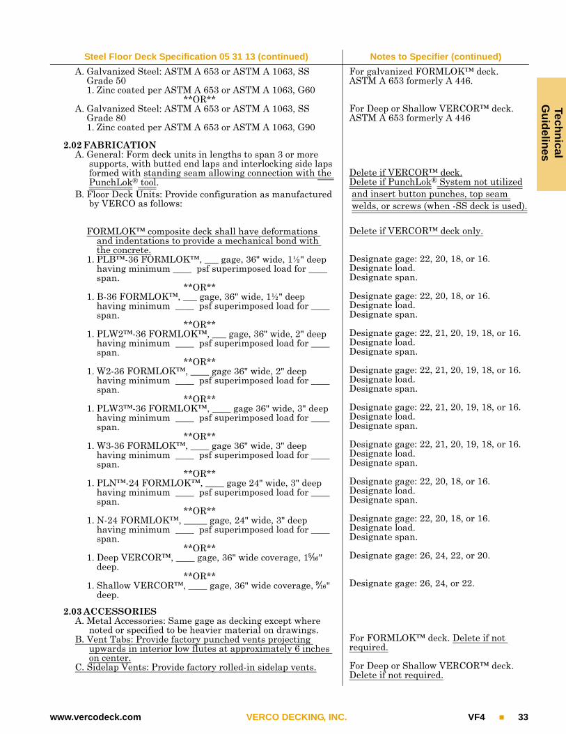
2.02 FABRICATIONA. General: Form deck units in lengths to span 3 or more
supports, with butted end laps and interlocking side laps formed with standing seam allowing connection with the PunchLok® tool.
B. Floor Deck Units: Provide configuration as manufactured by VERCO as follows:
FORMLOK™ composite deck shall have deformations and indentations to provide a mechanical bond with the concrete.
1. PLB™-36 FORMLOK™, ___ gage, 36" wide, 1½" deep having minimum ____ psf superimposed load for ____ span.
**OR**1. B-36 FORMLOK™, ___ gage, 36" wide, 1½" deep
having minimum ____ psf superimposed load for ____ span.
**OR**1. PLW2™-36 FORMLOK™, ___ gage, 36" wide, 2" deep
having minimum ____ psf superimposed load for ____ span.
**OR**1. W2-36 FORMLOK™, ____ gage 36" wide, 2" deep
having minimum ____ psf superimposed load for ____ span.
**OR**1. PLW3™-36 FORMLOK™, ____ gage 36" wide, 3" deep
having minimum ____ psf superimposed load for ____ span.
**OR**1. W3-36 FORMLOK™, ____ gage 36" wide, 3" deep
having minimum ____ psf superimposed load for ____ span.
**OR**1. PLN™-24 FORMLOK™, ____ gage 24" wide, 3" deep
having minimum ____ psf superimposed load for ____ span.
**OR**1. N-24 FORMLOK™, _____ gage, 24" wide, 3" deep
having minimum ____ psf superimposed load for ____ span.
**OR**1. Deep VERCOR™, ____ gage, 36" wide coverage, 15-QY"
deep.**OR**
1. Shallow VERCOR™, ____ gage, 36" wide coverage, (-QY" deep.
Delete if VERCOR™ deck.Delete if PunchLok® System not utilized and insert button punches, top seam welds, or screws (when -SS deck is used).
Delete if VERCOR™ deck only.
Designate gage: 22, 20, 18, or 16.Designate load.Designate span.
Designate gage: 22, 20, 18, or 16.Designate load.Designate span.
Designate gage: 22, 21, 20, 19, 18, or 16.Designate load.Designate span.
Designate gage: 22, 21, 20, 19, 18, or 16.Designate load.Designate span.
Designate gage: 22, 21, 20, 19, 18, or 16.Designate load.Designate span.
Designate gage: 22, 21, 20, 19, 18, or 16.Designate load.Designate span.
Designate gage: 22, 20, 18, or 16.Designate load.Designate span.
Designate gage: 22, 20, 18, or 16.Designate load.Designate span.
Designate gage: 26, 24, 22, or 20.
Designate gage: 26, 24, or 22.
2.03 ACCESSORIESA. Metal Accessories: Same gage as decking except where
noted or specified to be heavier material on drawings.B. Vent Tabs: Provide factory punched vents projecting
upwards in interior low flutes at approximately 6 inches on center.
C. Sidelap Vents: Provide factory rolled-in sidelap vents.
For FORMLOK™ deck. Delete if not required.
For Deep or Shallow VERCOR™ deck. Delete if not required.
Steel Floor Deck Specification 05 31 13 (continued) Notes to Specifier (continued)

Tech
nic
alG
uid
elin
es
34 VF4 VERCO DECKING, INC. www.vercodeck.com
PART 3 -- EXECUTION
3.01 INSPECTIONA. Check supporting members for correct layout and align-
ment.B. Verify that surfaces to receive floor deck are free of debris.C. Do not proceed with installation until defects are corrected.
3.02 INSTALLATIONA. General: Install floor deck units and accessories in accor-
dance with approved shop drawings.B. Placing Floor Deck Units:
1. Position on supporting steel framework and adjust to final position with ends bearing a minimum of 2 in. on supporting members.
2. Place units end to end before permanently fastening.3. Align ribs over entire length of run.
C. Fastening Deck Units:1. Secure to supporting members with !-W in. effective
diameter arc spot welds. If studs are welded through deck to structural steel,stud welds can replace arc spot welds.
**OR**1. Secure to supporting members with arc spot welds.
through #-I" diameter hole in 14 gage weld washer.2. Connect sidelaps with Verco PunchLok® tool to create
interlocking VSC connection at ___" on center. VSCs may be made in either direction.
**OR**
2. Connect sidelaps with button punches at ___" on center.3. Comply with AWS requirements and procedures for
welding sheet steel in structures.
For FORMLOK™ deck only.
For VERCOR™ deck only.
For FORMLOK™ deck only.Designate spacing. VSC = Verco Sidelap connection made with the PunchLok®
tool.
Designate spacing. Replace with top seam welds or screws (when -SS deck is used) if button punches not permitted.
Note: Maximum sidelap connection spac-ing for VSCs, BPs, TSWs, and screws (when -SS deck is used) is 36" on center.
3.03 PROTECTIONA. Do not use deck units for storage or working platforms until
permanently secured in position.B. Construction loads must not exceed flexural strength and
serviceability requirements of deck.C. Concrete must be placed with care, avoiding impacts by
dropping or dumping. Runways must be planked if using buggies. Heavy concentrated loads of concrete or crews and uniform loads exceeding 20 psf must be investigated for shoring consideration.
D. Calcium chloride and concrete admixtures containing chlo-ride salts shall not be used with FORMLOK™ deck.
*END OF SECTION*
Steel Floor Deck Specification 05 31 13 (continued) Notes to Specifier (continued)

Tech
nical
Gu
idelin
es
www.vercodeck.com VERCO DECKING, INC. VF4 35
Using the Tables Figure 19 highlights important considerations for using the deck tables. (This figure is based on the tables found on page 38 of this catalog.)
Allowable Superimposed Loads (psf)
Gage SpansMax
UCS1Span (ft-in.)
6'-0" 6'-6" 7'-0" 7'-6" 8'-0" 8'-6" 9'-0" 9'-6" 10'-0" 10'-6"
221 6'-2" 303 229 198 173 151 133 118 104 93 832 7'-3" 303 265 234 173 151 133 118 104 93 833 7'-4" 303 265 234 173 151 133 118 104 93 83
1 Max UCS = Maximum Unshored Clear Span (ft-in.) Shoring required in shaded areas to
7 Welds4 Welds
Allowable Diaphragm Shear Values, q (plf) and Flexibility Factors, F (in./lb x 106)
Gage WeldsSpan (ft-in.)
6'-0" 6'-6" 7'-0" 7'-6" 8'-0" 8'-6" 9'-0" 9'-6" 10'-0" 10'-6"
22
q4 2065 2026 1993 1965 1940 1918 1898 1881 1865 1851
F4 0.40 0.41 0.41 0.42 0.42 0.43 0.43 0.44 0.44 0.45
q7 2274 2220 2173 2133 2097 2066 2038 2013 1991 1971
F7 0.36 0.37 0.38 0.39 0.39 0.40 0.40 0.41 0.41 0.42
Profile shows weld locations (in this case, 4 or 7 welds per sheet).
Allowable Superimposed Load isthe load the composite slab can support in addition to the weight of the deck and concrete.
Shaded areas to the right of the black line indicate that shoring is required during construction. In this case, single spans longer than 6'-2", double spans longer than 7'-3", and triple spans longer than 7'-4" must be shored.
Concrete weight excluding FORM-LOK deck deflection allowance of 4 psf (NW) or 3 psf (LW).
Allowable Diaphragm Shear (q) and Flexibility Factor (F) based on 4 welds to support per 36" sheet.
Allowable Diaphragm Shear (q) and Flexibility Factor (F) based on 7 welds to support per 36" sheet.
Design information for the tables on each page.
FIGURE 19
Welded Wire Fabric (mesh)PLB™or B FORMLOK™
4 in. TOTAL SLAB DEPTH Normal Weight Concrete (145 pcf)
36.6 psf Galvanized or Phosphatized/Painted

PLB™or B FORMLOK™
1½" Deep Deck Galvanized or Phosphatized/Painted
B
SU
MM
AR
Y
36 VF4 VERCO DECKING, INC. www.vercodeck.com
Dimensions
Deck Weight and Section Properties
Attachment Patterns to Supports
Embossment Pattern
Gage
Weight (psf) Id for Deflection Moment Allowable Reactions per ft of Width (lb)
Galv G60
Phos/Painted
Single Span
(in.4/ft)
Multiple Spans(in.4/ft)
+Seff(in.3/ft )
–Seff(in.3/ft)
End Bearing Interior Bearing
2" 3" 4" 3" 4"
22 1.9 1.8 0.177 0.192 0.176 0.188 935 1076 1163 1559 1671
20 2.3 2.2 0.219 0.231 0.230 0.237 1301 1492 1609 2190 2340
18 2.9 2.8 0.302 0.306 0.314 0.331 2181 2484 2667 3714 3950
16 3.5 3.4 0.381 0.381 0.399 0.410 3265 3699 3955 5607 5938
Note: Section properties are based on Fy = 50,000 psi.
36"
1½"
3½" 2½" 6"
1¾"
36/4
36/7

PLB™or B FORMLOK™
3½ in. TOTAL SLAB DEPTH Normal Weight Concrete (145 pcf)
30.6 psf Galvanized or Phosphatized/Painted
B 3
½"
NW
7 Welds
4 Welds7 Welds
4 Welds
www.vercodeck.com VERCO DECKING, INC. VF4 37
Deck Weight and Section Properties
Gage
Weight (psf) Id for Deflection Moment Allowable Reactions per ft of Width (lb)
Galv G60
Phos/Painted
Single Span
(in.4/ft)
Multiple Spans(in.4/ft)
+Seff(in.3/ft )
–Seff(in.3/ft)
End Bearing Interior Bearing
2" 3" 4" 3" 4"
22 1.9 1.8 0.177 0.192 0.176 0.188 935 1076 1163 1559 1671
20 2.3 2.2 0.219 0.231 0.230 0.237 1301 1492 1609 2190 2340
18 2.9 2.8 0.302 0.306 0.314 0.331 2181 2484 2667 3714 3950
16 3.5 3.4 0.381 0.381 0.399 0.410 3265 3699 3955 5607 5938
Allowable Superimposed Loads (psf)
Gage SpansMax.UCS1
Span (ft-in.)
6'-0" 6'-6" 7'-0" 7'-6" 8'-0" 8'-6" 9'-0" 9'-6" 10'-0" 10'-6" 11'-0"
22
1 6'-6" 261 228 170 148 130 115 101 90 80 71 64
2 7'-8" 261 228 202 180 130 115 101 90 80 71 64
3 7'-9" 261 228 202 180 130 115 101 90 80 71 64
20
1 7'-9" 274 240 212 189 138 122 108 96 85 76 68
2 9'-1" 274 240 212 189 170 153 140 96 85 76 68
3 9'-3" 274 240 212 189 170 153 140 96 85 76 68
18
1 8'-10" 297 260 230 205 184 166 119 106 95 85 76
2 10'-8" 297 260 230 205 184 166 151 138 127 117 76
3 11'-0" 297 260 230 205 184 166 151 138 127 117 108
16
1 9'-6" 297 260 230 205 184 166 151 138 94 84 75
2 11'-10" 297 260 230 205 184 166 151 138 127 117 108
3 11'-7" 297 260 230 205 184 166 151 138 127 117 108
1 Max. UCS = Maximum Unshored Clear Span (ft-in.) Shoring required in shaded areas to right of heavy line.
Allowable Diaphragm Shear Values, q (plf) and Flexibility Factors, F (in./lb x 106)
Gage WeldsSpan (ft-in.)
6'-0" 6'-6" 7'-0" 7'-6" 8'-0" 8'-6" 9'-0" 9'-6" 10'-0" 10'-6" 11'-0"
22
q4 1825 1787 1754 1726 1701 1679 1659 1642 1626 1612 1599
F4 0.45 0.46 0.47 0.48 0.48 0.49 0.50 0.50 0.51 0.51 0.52
q7 2035 1981 1934 1893 1858 1827 1799 1774 1752 1732 1713
F7 0.41 0.42 0.43 0.44 0.44 0.45 0.46 0.46 0.47 0.48 0.48
20
q4 1893 1847 1808 1773 1743 1717 1694 1673 1654 1637 1621
F4 0.40 0.41 0.42 0.42 0.43 0.44 0.44 0.45 0.45 0.46 0.46
q7 2145 2079 2023 1975 1932 1895 1861 1832 1805 1780 1758
F7 0.35 0.36 0.37 0.38 0.39 0.40 0.40 0.41 0.42 0.42 0.43
18
q4 2046 1985 1932 1887 1847 1812 1781 1753 1728 1705 1684
F4 0.32 0.33 0.34 0.35 0.35 0.36 0.37 0.37 0.38 0.38 0.39
q7 2381 2294 2219 2155 2098 2048 2004 1964 1929 1896 1867
F7 0.27 0.28 0.29 0.30 0.31 0.32 0.33 0.33 0.34 0.34 0.35
16
q4 2215 2138 2073 2016 1966 1922 1883 1848 1816 1788 1762
F4 0.26 0.27 0.28 0.29 0.30 0.30 0.31 0.32 0.32 0.33 0.33
q7 2634 2525 2432 2351 2280 2218 2162 2113 2068 2027 1991
F7 0.22 0.23 0.24 0.25 0.26 0.26 0.27 0.28 0.28 0.29 0.29

7 Welds
4 Welds
B 4
"N
WPLB™or B FORMLOK™
4 in. TOTAL SLAB DEPTH Normal Weight Concrete (145 pcf)
36.6 psf Galvanized or Phosphatized/Painted
38 VF4 VERCO DECKING, INC. www.vercodeck.com
Deck Weight and Section Properties
Gage
Weight (psf) Id for Deflection Moment Allowable Reactions per ft of Width (lb)
Galv G60
Phos/Painted
Single Span
(in.4/ft)
Multiple Spans(in.4/ft)
+Seff(in.3/ft )
–Seff(in.3/ft)
End Bearing Interior Bearing
2" 3" 4" 3" 4"
22 1.9 1.8 0.177 0.192 0.176 0.188 935 1076 1163 1559 1671
20 2.3 2.2 0.219 0.231 0.230 0.237 1301 1492 1609 2190 2340
18 2.9 2.8 0.302 0.306 0.314 0.331 2181 2484 2667 3714 3950
16 3.5 3.4 0.381 0.381 0.399 0.410 3265 3699 3955 5607 5938
Allowable Superimposed Loads (psf)
Gage SpansMax.UCS1
Span (ft-in.)
6'-0" 6'-6" 7'-0" 7'-6" 8'-0" 8'-6" 9'-0" 9'-6" 10'-0" 10'-6" 11'-0"
22
1 6'-2" 303 229 198 173 151 133 118 104 93 83 74
2 7'-3" 303 265 234 173 151 133 118 104 93 83 74
3 7'-4" 303 265 234 173 151 133 118 104 93 83 74
20
1 7'-5" 318 279 246 183 160 141 125 111 99 89 79
2 8'-8" 318 279 246 220 197 178 125 111 99 89 79
3 8'-9" 318 279 246 220 197 178 125 111 99 89 79
18
1 8'-5" 344 301 266 237 213 155 138 123 109 98 88
2 10'-2" 344 301 266 237 213 192 175 160 147 98 88
3 10'-5" 344 301 266 237 213 192 175 160 147 98 88
16
1 9'-1" 342 300 265 236 212 192 174 121 108 97 87
2 11'-3" 342 300 265 236 212 192 174 159 146 135 125
3 11'-2" 342 300 265 236 212 192 174 159 146 135 125
1 Max. UCS = Maximum Unshored Clear Span (ft-in.) Shoring required in shaded areas to right of heavy line.
Allowable Diaphragm Shear Values, q (plf) and Flexibility Factors, F (in./lb x 106)
Gage WeldsSpan (ft-in.)
6'-0" 6'-6" 7'-0" 7'-6" 8'-0" 8'-6" 9'-0" 9'-6" 10'-0" 10'-6" 11'-0"
22
q4 2065 2026 1993 1965 1940 1918 1898 1881 1865 1851 1838
F4 0.40 0.41 0.41 0.42 0.42 0.43 0.43 0.44 0.44 0.45 0.45
q7 2274 2220 2173 2133 2097 2066 2038 2013 1991 1971 1952
F7 0.36 0.37 0.38 0.39 0.39 0.40 0.40 0.41 0.41 0.42 0.42
20
q4 2132 2086 2047 2012 1983 1956 1933 1912 1893 1876 1860
F4 0.35 0.36 0.37 0.37 0.38 0.38 0.39 0.39 0.40 0.40 0.40
q7 2384 2318 2262 2214 2171 2134 2100 2071 2044 2020 1997
F7 0.32 0.32 0.33 0.34 0.35 0.35 0.36 0.36 0.37 0.37 0.38
18
q4 2285 2224 2171 2126 2086 2051 2020 1992 1967 1944 1923
F4 0.29 0.29 0.30 0.31 0.31 0.32 0.32 0.33 0.33 0.34 0.34
q7 2620 2533 2459 2394 2337 2287 2243 2203 2168 2135 2106
F7 0.25 0.26 0.27 0.27 0.28 0.29 0.29 0.30 0.30 0.31 0.31
16
q4 2454 2377 2312 2255 2205 2161 2122 2087 2055 2027 2001
F4 0.24 0.25 0.25 0.26 0.26 0.27 0.27 0.28 0.28 0.29 0.29
q7 2873 2764 2671 2590 2519 2457 2401 2352 2307 2267 2230
F7 0.20 0.21 0.22 0.23 0.23 0.24 0.24 0.25 0.25 0.26 0.26

PLB™or B FORMLOK™
4½ in. TOTAL SLAB DEPTH Normal Weight Concrete (145 pcf)
42.7 psf Galvanized or Phosphatized/Painted
B 4
½"
NW
7 Welds4 Welds
www.vercodeck.com VERCO DECKING, INC. VF4 39
Deck Weight and Section Properties
Gage
Weight (psf) Id for Deflection Moment Allowable Reactions per ft of Width (lb)
Galv G60
Phos/Painted
Single Span
(in.4/ft)
Multiple Spans(in.4/ft)
+Seff(in.3/ft )
–Seff(in.3/ft)
End Bearing Interior Bearing
2" 3" 4" 3" 4"
22 1.9 1.8 0.177 0.192 0.176 0.188 935 1076 1163 1559 1671
20 2.3 2.2 0.219 0.231 0.230 0.237 1301 1492 1609 2190 2340
18 2.9 2.8 0.302 0.306 0.314 0.331 2181 2484 2667 3714 3950
16 3.5 3.4 0.381 0.381 0.399 0.410 3265 3699 3955 5607 5938
Allowable Superimposed Loads (psf)
Gage SpansMax.UCS1
Span (ft-in.)
6'-0" 6'-6" 7'-0" 7'-6" 8'-0" 8'-6" 9'-0" 9'-6" 10'-0" 10'-6" 11'-0"
22
1 5'-11" 306 263 227 198 174 153 135 120 107 95 85
2 6'-11" 348 304 227 198 174 153 135 120 107 95 85
3 7'-0" 348 304 269 198 174 153 135 120 107 95 85
20
1 7'-1" 365 319 282 210 184 162 144 128 114 102 91
2 8'-3" 365 319 282 252 226 162 144 128 114 102 91
3 8'-4" 365 319 282 252 226 162 144 128 114 102 91
18
1 8'-1" 393 344 304 271 244 178 158 140 125 112 101
2 9'-9" 393 344 304 271 244 220 200 183 125 112 101
3 10'-0" 393 344 304 271 244 220 200 183 168 112 101
16
1 8'-8" 391 342 302 269 242 219 156 138 124 111 99
2 10'-9" 391 342 302 269 242 219 199 182 167 154 99
3 10'-9" 391 342 302 269 242 219 199 182 167 154 99
1 Max. UCS = Maximum Unshored Clear Span (ft-in.) Shoring required in shaded areas to right of heavy line.
Allowable Diaphragm Shear Values, q (plf) and Flexibility Factors, F (in./lb x 106)
Gage WeldsSpan (ft-in.)
6'-0" 6'-6" 7'-0" 7'-6" 8'-0" 8'-6" 9'-0" 9'-6" 10'-0" 10'-6" 11'-0"
22
q4 2304 2265 2232 2204 2179 2157 2138 2120 2104 2090 2077
F4 0.36 0.36 0.37 0.37 0.38 0.38 0.39 0.39 0.39 0.39 0.40
q7 2513 2459 2412 2372 2336 2305 2277 2252 2230 2210 2191
F7 0.33 0.34 0.34 0.35 0.35 0.36 0.36 0.37 0.37 0.37 0.38
20
q4 2371 2325 2286 2252 2222 2195 2172 2151 2132 2115 2099
F4 0.32 0.32 0.33 0.33 0.34 0.34 0.35 0.35 0.35 0.36 0.36
q7 2623 2557 2501 2453 2410 2373 2340 2310 2283 2259 2237
F7 0.29 0.29 0.30 0.31 0.31 0.32 0.32 0.33 0.33 0.33 0.34
18
q4 2524 2463 2410 2365 2325 2290 2259 2231 2206 2183 2162
F4 0.26 0.26 0.27 0.28 0.28 0.28 0.29 0.29 0.30 0.30 0.30
q7 2859 2772 2698 2633 2576 2527 2482 2442 2407 2374 2345
F7 0.23 0.24 0.24 0.25 0.25 0.26 0.26 0.27 0.27 0.27 0.28
16
q4 2693 2616 2551 2494 2444 2400 2361 2326 2295 2266 2240
F4 0.22 0.22 0.23 0.23 0.24 0.24 0.25 0.25 0.25 0.26 0.26
q7 3112 3003 2910 2829 2758 2696 2640 2591 2546 2506 2469
F7 0.19 0.19 0.20 0.21 0.21 0.22 0.22 0.22 0.23 0.23 0.24

7 Welds
4 Welds
B 5
"N
WPLB™or B FORMLOK™
5 in. TOTAL SLAB DEPTH Normal Weight Concrete (145 pcf)
48.7 psf Galvanized or Phosphatized/Painted 1 Hour Fire Rating
40 VF4 VERCO DECKING, INC. www.vercodeck.com
Deck Weight and Section Properties
Gage
Weight (psf) Id for Deflection Moment Allowable Reactions per ft of Width (lb)
Galv G60
Phos/Painted
Single Span
(in.4/ft)
Multiple Spans(in.4/ft)
+Seff(in.3/ft )
–Seff(in.3/ft)
End Bearing Interior Bearing
2" 3" 4" 3" 4"
22 1.9 1.8 0.177 0.192 0.176 0.188 935 1076 1163 1559 1671
20 2.3 2.2 0.219 0.231 0.230 0.237 1301 1492 1609 2190 2340
18 2.9 2.8 0.302 0.306 0.314 0.331 2181 2484 2667 3714 3950
16 3.5 3.4 0.381 0.381 0.399 0.410 3265 3699 3955 5607 5938
Allowable Superimposed Loads (psf)
Gage SpansMax.UCS1
Span (ft-in.)
6'-0" 6'-6" 7'-0" 7'-6" 8'-0" 8'-6" 9'-0" 9'-6" 10'-0" 10'-6" 11'-0"
22
1 5’-8” 347 297 257 224 197 173 153 136 121 108 96
2 6’-8” 393 344 257 224 197 173 153 136 121 108 96
3 6’-9” 393 344 257 224 197 173 153 136 121 108 96
20
1 6'-9" 400 361 272 237 208 184 163 145 129 115 103
2 7'-11" 400 361 319 284 208 184 163 145 129 115 103
3 8'-0" 400 361 319 284 255 184 163 145 129 115 103
18
1 7'-9" 400 389 344 306 227 201 178 159 142 127 114
2 9'-4" 400 389 344 306 275 249 226 159 142 127 114
3 9'-7" 400 389 344 306 275 249 226 207 142 127 114
16
1 8'-4" 400 386 341 304 273 198 176 157 140 125 112
2 10'-4" 400 386 341 304 273 247 224 205 188 125 112
3 10'-4" 400 386 341 304 273 247 224 205 188 125 112
1 Max. UCS = Maximum Unshored Clear Span (ft-in.) Shoring required in shaded areas to right of heavy line.
Allowable Diaphragm Shear Values, q (plf) and Flexibility Factors, F (in./lb x 106)
Gage WeldsSpan (ft-in.)
6'-0" 6'-6" 7'-0" 7'-6" 8'-0" 8'-6" 9'-0" 9'-6" 10'-0" 10'-6" 11'-0"
22
q4 2543 2504 2472 2443 2418 2396 2377 2359 2343 2329 2316
F4 0.32 0.33 0.33 0.34 0.34 0.34 0.35 0.35 0.35 0.35 0.36
q7 2752 2698 2651 2611 2575 2544 2516 2492 2469 2449 2431
F7 0.30 0.31 0.31 0.32 0.32 0.32 0.33 0.33 0.33 0.34 0.34
20
q4 2610 2564 2525 2491 2461 2434 2411 2390 2371 2354 2338
F4 0.29 0.29 0.30 0.30 0.31 0.31 0.31 0.31 0.32 0.32 0.32
q7 2862 2796 2740 2692 2649 2612 2579 2549 2522 2498 2476
F7 0.26 0.27 0.27 0.28 0.28 0.29 0.29 0.30 0.30 0.30 0.30
18
q4 2763 2702 2650 2604 2564 2529 2498 2470 2445 2422 2401
F4 0.24 0.24 0.25 0.25 0.25 0.26 0.26 0.26 0.27 0.27 0.27
q7 3098 3011 2937 2872 2816 2766 2721 2682 2646 2613 2584
F7 0.21 0.22 0.22 0.23 0.23 0.24 0.24 0.24 0.25 0.25 0.25
16
q4 2932 2856 2790 2733 2683 2639 2600 2565 2534 2505 2479
F4 0.20 0.20 0.21 0.21 0.22 0.22 0.22 0.23 0.23 0.23 0.24
q7 3351 3242 3149 3068 2997 2935 2880 2830 2785 2745 2708
F7 0.17 0.18 0.19 0.19 0.19 0.20 0.20 0.21 0.21 0.21 0.22

PLB™or B FORMLOK™
6 in. TOTAL SLAB DEPTH Normal Weight Concrete (145 pcf)
60.8 psf Galvanized or Phosphatized/Painted 2 Hour Fire Rating
B 6
"N
W
7 Welds
4 Welds
7 Welds
4 Welds
www.vercodeck.com VERCO DECKING, INC. VF4 41
Deck Weight and Section Properties
Gage
Weight (psf) Id for Deflection Moment Allowable Reactions per ft of Width (lb)
Galv G60
Phos/Painted
Single Span
(in.4/ft)
Multiple Spans(in.4/ft)
+Seff(in.3/ft )
–Seff(in.3/ft)
End Bearing Interior Bearing
2" 3" 4" 3" 4"
22 1.9 1.8 0.177 0.192 0.176 0.188 935 1076 1163 1559 1671
20 2.3 2.2 0.219 0.231 0.230 0.237 1301 1492 1609 2190 2340
18 2.9 2.8 0.302 0.306 0.314 0.331 2181 2484 2667 3714 3950
16 3.5 3.4 0.381 0.381 0.399 0.410 3265 3699 3955 5607 5938
Allowable Superimposed Loads (psf)
Gage SpansMax.UCS1
Span (ft-in.)
6'-0" 6'-6" 7'-0" 7'-6" 8'-0" 8'-6" 9'-0" 9'-6" 10'-0" 10'-6" 11'-0"
22
1 5'-4" 400 369 320 279 244 215 191 169 151 134 120
2 6'-2" 400 369 320 279 244 215 191 169 151 134 120
3 6'-3" 400 369 320 279 244 215 191 169 151 134 120
20
1 6'-3" 400 389 337 295 259 228 202 180 160 143 128
2 7'-4" 400 400 395 295 259 228 202 180 160 143 128
3 7'-5" 400 400 395 295 259 228 202 180 160 143 128
18
1 7'-3" 400 400 400 321 282 250 222 197 177 158 142
2 8'-8" 400 400 400 379 340 308 222 197 177 158 142
3 8'-11" 400 400 400 379 340 308 222 197 177 158 142
16
1 7'-10" 400 400 400 376 279 246 219 195 174 156 140
2 9'-7" 400 400 400 376 337 305 277 253 174 156 140
3 9'-8" 400 400 400 376 337 305 277 253 174 156 140
1 Max. UCS = Maximum Unshored Clear Span (ft-in.) Shoring required in shaded areas to right of heavy line.
Allowable Diaphragm Shear Values, q (plf) and Flexibility Factors, F (in./lb x 106)
Gage WeldsSpan (ft-in.)
6'-0" 6'-6" 7'-0" 7'-6" 8'-0" 8'-6" 9'-0" 9'-6" 10'-0" 10'-6" 11'-0"
22
q4 3021 2983 2950 2921 2896 2874 2855 2837 2822 2807 2794
F4 0.27 0.28 0.28 0.28 0.28 0.29 0.29 0.29 0.29 0.29 0.29
q7 3230 3176 3129 3089 3053 3022 2995 2970 2947 2927 2909
F7 0.26 0.26 0.26 0.27 0.27 0.27 0.28 0.28 0.28 0.28 0.28
20
q4 3088 3042 3003 2969 2939 2912 2889 2868 2849 2832 2817
F4 0.24 0.25 0.25 0.25 0.26 0.26 0.26 0.26 0.26 0.27 0.27
q7 3340 3275 3219 3170 3128 3090 3057 3027 3000 2976 2954
F7 0.23 0.23 0.23 0.24 0.24 0.24 0.25 0.25 0.25 0.25 0.25
18
q4 3241 3180 3128 3082 3042 3007 2976 2948 2923 2900 2880
F4 0.20 0.21 0.21 0.21 0.21 0.22 0.22 0.22 0.22 0.22 0.23
q7 3577 3490 3415 3350 3294 3244 3199 3160 3124 3092 3062
F7 0.18 0.19 0.19 0.19 0.20 0.20 0.20 0.21 0.21 0.21 0.21
16
q4 3410 3334 3268 3211 3161 3117 3078 3043 3012 2983 2957
F4 0.17 0.17 0.18 0.18 0.18 0.19 0.19 0.19 0.19 0.20 0.20
q7 3829 3721 3627 3546 3476 3413 3358 3308 3263 3223 3186
F7 0.15 0.16 0.16 0.16 0.17 0.17 0.17 0.18 0.18 0.18 0.18

B 3
½"
LW
PLB™or B FORMLOK™
3½ in. TOTAL SLAB DEPTH Light Weight Concrete (110 pcf)
23.2 psf Galvanized or Phosphatized/Painted
7 Welds
4 Welds7 Welds
4 Welds
42 VF4 VERCO DECKING, INC. www.vercodeck.com
Deck Weight and Section Properties
Gage
Weight (psf) Id for Deflection Moment Allowable Reactions per ft of Width (lb)
Galv G60
Phos/Painted
Single Span
(in.4/ft)
Multiple Spans(in.4/ft)
+Seff(in.3/ft )
–Seff(in.3/ft)
End Bearing Interior Bearing
2" 3" 4" 3" 4"
22 1.9 1.8 0.177 0.192 0.176 0.188 935 1076 1163 1559 1671
20 2.3 2.2 0.219 0.231 0.230 0.237 1301 1492 1609 2190 2340
18 2.9 2.8 0.302 0.306 0.314 0.331 2181 2484 2667 3714 3950
16 3.5 3.4 0.381 0.381 0.399 0.410 3265 3699 3955 5607 5938
Allowable Superimposed Loads (psf)
Gage SpansMax.UCS1
Span (ft-in.)
6'-0" 6'-6" 7'-0" 7'-6" 8'-0" 8'-6" 9'-0" 9'-6" 10'-0" 10'-6" 11'-0"
22
1 7'-0" 261 228 202 156 137 122 109 97 87 78 71
2 8'-3" 261 228 202 180 161 122 109 97 87 78 71
3 8'-4" 261 228 202 180 161 122 109 97 87 78 71
20
1 8'-5" 274 240 212 189 170 129 115 103 93 84 75
2 9'-10" 274 240 212 189 170 153 140 119 93 84 75
3 10'-0" 274 240 212 189 170 153 140 119 102 84 75
18
1 9'-8" 297 260 230 205 184 166 151 135 102 92 83
2 11'-7" 297 260 230 205 184 166 151 135 116 100 87
3 11'-9" 297 260 230 205 184 166 151 135 116 100 87
16
1 10'-4" 297 260 230 205 184 166 151 138 127 91 83
2 12'-9" 297 260 230 205 184 166 151 138 127 111 96
3 12'-4" 297 260 230 205 184 166 151 138 127 111 96
1 Max. UCS = Maximum Unshored Clear Span (ft-in.) Shoring required in shaded areas to right of heavy line.
Allowable Diaphragm Shear Values, q (plf) and Flexibility Factors, F (in./lb x 106)
Gage WeldsSpan (ft-in.)
6'-0" 6'-6" 7'-0" 7'-6" 8'-0" 8'-6" 9'-0" 9'-6" 10'-0" 10'-6" 11'-0"
22
q4 1501 1463 1430 1401 1376 1354 1335 1317 1302 1287 1275
F4 0.55 0.56 0.58 0.59 0.60 0.61 0.62 0.63 0.63 0.64 0.65
q7 1711 1656 1609 1569 1534 1502 1475 1450 1427 1407 1389
F7 0.48 0.50 0.51 0.53 0.54 0.55 0.56 0.57 0.58 0.59 0.59
20
q4 1569 1523 1483 1449 1419 1393 1369 1348 1329 1312 1297
F4 0.48 0.49 0.51 0.52 0.53 0.54 0.55 0.56 0.57 0.57 0.58
q7 1820 1755 1699 1650 1608 1570 1537 1507 1480 1456 1434
F7 0.41 0.43 0.44 0.46 0.47 0.48 0.49 0.50 0.51 0.52 0.52
18
q4 1722 1660 1608 1562 1523 1487 1456 1428 1403 1380 1360
F4 0.38 0.39 0.41 0.42 0.43 0.44 0.45 0.46 0.46 0.47 0.48
q7 2057 1970 1895 1830 1774 1724 1680 1640 1604 1572 1542
F7 0.32 0.33 0.34 0.36 0.37 0.38 0.39 0.40 0.41 0.41 0.42
16
q4 1890 1814 1748 1691 1641 1597 1558 1523 1492 1463 1438
F4 0.31 0.32 0.33 0.34 0.36 0.36 0.37 0.38 0.39 0.40 0.41
q7 2310 2201 2107 2027 1956 1893 1838 1788 1743 1703 1666
F7 0.25 0.26 0.28 0.29 0.30 0.31 0.32 0.33 0.33 0.34 0.35

PLB™or B FORMLOK™
4 in. TOTAL SLAB DEPTH Light Weight Concrete (145 pcf)
27.8 psf Galvanized or Phosphatized/Painted 1 Hour Fire Rating
B 4
"L
W
7 Welds
4 Welds
www.vercodeck.com VERCO DECKING, INC. VF4 43
Deck Weight and Section Properties
Gage
Weight (psf) Id for Deflection Moment Allowable Reactions per ft of Width (lb)
Galv G60
Phos/Painted
Single Span
(in.4/ft)
Multiple Spans(in.4/ft)
+Seff(in.3/ft )
–Seff(in.3/ft)
End Bearing Interior Bearing
2" 3" 4" 3" 4"
22 1.9 1.8 0.177 0.192 0.176 0.188 935 1076 1163 1559 1671
20 2.3 2.2 0.219 0.231 0.230 0.237 1301 1492 1609 2190 2340
18 2.9 2.8 0.302 0.306 0.314 0.331 2181 2484 2667 3714 3950
16 3.5 3.4 0.381 0.381 0.399 0.410 3265 3699 3955 5607 5938
Allowable Superimposed Loads (psf)
Gage SpansMax.UCS1
Span (ft-in.)
6'-0" 6'-6" 7'-0" 7'-6" 8'-0" 8'-6" 9'-0" 9'-6" 10'-0" 10'-6" 11'-0"
22
1 6'-9" 303 265 206 181 160 142 126 113 101 91 82
2 7'-11" 303 265 234 209 160 142 126 113 101 91 82
3 8'-0" 303 265 234 209 188 142 126 113 101 91 82
20
1 8'-1" 318 279 246 220 197 150 134 120 108 97 88
2 9'-5" 318 279 246 220 197 178 162 120 108 97 88
3 9'-7" 318 279 246 220 197 178 162 148 108 97 88
18
1 9'-2" 344 301 266 237 213 192 175 131 118 106 96
2 11'-1" 344 301 266 237 213 192 175 160 147 135 125
3 11'-4" 344 301 266 237 213 192 175 160 147 135 125
16
1 9'-10" 342 300 265 236 212 192 174 159 117 105 95
2 12'-3" 342 300 265 236 212 192 174 159 146 135 125
3 11'-11" 342 300 265 236 212 192 174 159 146 135 125
1 Max. UCS = Maximum Unshored Clear Span (ft-in.) Shoring required in shaded areas to right of heavy line.
Allowable Diaphragm Shear Values, q (plf) and Flexibility Factors, F (in./lb x 106)
Gage WeldsSpan (ft-in.)
6'-0" 6'-6" 7'-0" 7'-6" 8'-0" 8'-6" 9'-0" 9'-6" 10'-0" 10'-6" 11'-0"
22
q4 1659 1621 1588 1559 1534 1512 1493 1475 1460 1445 1433
F4 0.50 0.51 0.52 0.53 0.54 0.55 0.55 0.56 0.56 0.57 0.58
q7 1869 1814 1767 1727 1692 1660 1633 1608 1585 1565 1547
F7 0.44 0.45 0.47 0.48 0.49 0.50 0.50 0.51 0.52 0.53 0.53
20
q4 1726 1680 1641 1607 1577 1551 1527 1506 1487 1470 1455
F4 0.44 0.45 0.46 0.47 0.48 0.49 0.49 0.50 0.51 0.51 0.52
q7 1978 1913 1857 1808 1766 1728 1695 1665 1638 1614 1592
F7 0.38 0.39 0.41 0.42 0.43 0.44 0.44 0.45 0.46 0.47 0.47
18
q4 1880 1818 1766 1720 1681 1645 1614 1586 1561 1538 1518
F4 0.35 0.36 0.37 0.38 0.39 0.40 0.40 0.41 0.42 0.42 0.43
q7 2215 2128 2053 1988 1932 1882 1838 1798 1762 1730 1700
F7 0.29 0.31 0.32 0.33 0.34 0.35 0.35 0.36 0.37 0.38 0.38
16
q4 2048 1972 1906 1849 1799 1755 1716 1681 1650 1621 1596
F4 0.28 0.30 0.31 0.32 0.32 0.33 0.34 0.35 0.35 0.36 0.37
q7 2468 2359 2265 2185 2114 2051 1996 1946 1901 1861 1824
F7 0.24 0.25 0.26 0.27 0.28 0.28 0.29 0.30 0.31 0.31 0.32

B 4
¾"
LW
PLB™or B FORMLOK™
4¾ in. TOTAL SLAB DEPTH Light Weight Concrete (110 pcf)
34.7 psf Galvanized or Phosphatized/Painted 2 Hour Fire Rating
7 Welds
4 Welds7 Welds
4 Welds
44 VF4 VERCO DECKING, INC. www.vercodeck.com
Deck Weight and Section Properties
Gage
Weight (psf) Id for Deflection Moment Allowable Reactions per ft of Width (lb)
Galv G60
Phos/Painted
Single Span
(in.4/ft)
Multiple Spans(in.4/ft)
+Seff(in.3/ft )
–Seff(in.3/ft)
End Bearing Interior Bearing
2" 3" 4" 3" 4"
22 1.9 1.8 0.177 0.192 0.176 0.188 935 1076 1163 1559 1671
20 2.3 2.2 0.219 0.231 0.230 0.237 1301 1492 1609 2190 2340
18 2.9 2.8 0.302 0.306 0.314 0.331 2181 2484 2667 3714 3950
16 3.5 3.4 0.381 0.381 0.399 0.410 3265 3699 3955 5607 5938
Allowable Superimposed Loads (psf)
Gage SpansMax.UCS1
Span (ft-in.)
6'-0" 6'-6" 7'-0" 7'-6" 8'-0" 8'-6" 9'-0" 9'-6" 10'-0" 10'-6" 11'-0"
22
1 6'-4" 370 290 253 221 195 173 155 138 124 112 101
2 7'-5" 370 324 286 221 195 173 155 138 124 112 101
3 7'-6" 370 324 286 255 195 173 155 138 124 112 101
20
1 7'-7" 389 340 301 268 206 183 163 146 132 119 107
2 8'-10" 389 340 301 268 241 217 163 146 132 119 107
3 8'-11" 389 340 301 268 241 217 163 146 132 119 107
18
1 8'-8" 400 366 324 289 259 234 178 160 144 130 118
2 10'-5" 400 366 324 289 259 234 213 195 179 130 118
3 10'-8" 400 366 324 289 259 234 213 195 179 165 118
16
1 9'-3" 400 364 321 287 257 233 211 158 142 128 116
2 11'-6" 400 364 321 287 257 233 211 193 177 164 151
3 11'-5" 400 364 321 287 257 233 211 193 177 164 151
1 Max. UCS = Maximum Unshored Clear Span (ft-in.) Shoring required in shaded areas to right of heavy line.
Allowable Diaphragm Shear Values, q (plf) and Flexibility Factors, F (in./lb x 106)
Gage WeldsSpan (ft-in.)
6'-0" 6'-6" 7'-0" 7'-6" 8'-0" 8'-6" 9'-0" 9'-6" 10'-0" 10'-6" 11'-0"
22
q4 1896 1858 1825 1796 1771 1749 1730 1712 1697 1682 1669
F4 0.43 0.44 0.45 0.46 0.47 0.47 0.48 0.48 0.49 0.49 0.49
q7 2105 2051 2004 1964 1929 1897 1870 1845 1822 1802 1784
F7 0.39 0.40 0.41 0.42 0.43 0.43 0.44 0.45 0.45 0.46 0.46
20
q4 1963 1917 1878 1844 1814 1788 1764 1743 1724 1707 1692
F4 0.38 0.39 0.40 0.41 0.41 0.42 0.43 0.43 0.44 0.44 0.44
q7 2215 2150 2094 2045 2003 1965 1932 1902 1875 1851 1829
F7 0.34 0.35 0.36 0.37 0.38 0.38 0.39 0.40 0.40 0.41 0.41
18
q4 2117 2055 2003 1957 1917 1882 1851 1823 1798 1775 1755
F4 0.31 0.32 0.33 0.33 0.34 0.35 0.35 0.36 0.36 0.37 0.37
q7 2452 2365 2290 2225 2169 2119 2074 2035 1999 1967 1937
F7 0.27 0.28 0.28 0.29 0.30 0.31 0.31 0.32 0.33 0.33 0.34
16
q4 2285 2209 2143 2086 2036 1992 1953 1918 1887 1858 1833
F4 0.26 0.26 0.27 0.28 0.29 0.29 0.30 0.30 0.31 0.31 0.32
q7 2705 2596 2502 2421 2351 2288 2233 2183 2138 2098 2061
F7 0.22 0.22 0.23 0.24 0.25 0.25 0.26 0.27 0.27 0.28 0.28

PLB™or B FORMLOK™
5¾ in. TOTAL SLAB DEPTH Light Weight Concrete (110 pcf)
43.8 psf Galvanized or Phosphatized/Painted 3 Hour Fire Rating
B 5
¾"
LW
7 Welds
4 Welds
www.vercodeck.com VERCO DECKING, INC. VF4 45
Deck Weight and Section Properties
Gage
Weight (psf) Id for Deflection Moment Allowable Reactions per ft of Width (lb)
Galv G60
Phos/Painted
Single Span
(in.4/ft)
Multiple Spans(in.4/ft)
+Seff(in.3/ft )
–Seff(in.3/ft)
End Bearing Interior Bearing
2" 3" 4" 3" 4"
22 1.9 1.8 0.177 0.192 0.176 0.188 935 1076 1163 1559 1671
20 2.3 2.2 0.219 0.231 0.230 0.237 1301 1492 1609 2190 2340
18 2.9 2.8 0.302 0.306 0.314 0.331 2181 2484 2667 3714 3950
16 3.5 3.4 0.381 0.381 0.399 0.410 3265 3699 3955 5607 5938
Allowable Superimposed Loads (psf)
Gage SpansMax.UCS1
Span (ft-in.)
6'-0" 6'-6" 7'-0" 7'-6" 8'-0" 8'-6" 9'-0" 9'-6" 10'-0" 10'-6" 11'-0"
22
1 5'-11" 400 364 317 278 245 218 194 174 156 141 127
2 6'-11" 400 400 317 278 245 218 194 174 156 141 127
3 7'-0" 400 400 358 278 245 218 194 174 156 141 127
20
1 7'-1" 400 400 376 293 259 230 205 184 165 149 135
2 8'-3" 400 400 376 335 301 230 205 184 165 149 135
3 8'-4" 400 400 376 335 301 230 205 184 165 149 135
18
1 8'-1" 400 400 400 361 324 250 223 201 181 163 148
2 9'-8" 400 400 400 361 324 293 266 243 181 163 148
3 10'-0" 400 400 400 361 324 293 266 243 223 163 148
16
1 8'-8" 400 400 400 358 321 290 221 198 178 161 146
2 10'-9" 400 400 400 358 321 290 264 241 221 204 146
3 10'-8" 400 400 400 358 321 290 264 241 221 204 146
1 Max. UCS = Maximum Unshored Clear Span (ft-in.) Shoring required in shaded areas to right of heavy line.
Allowable Diaphragm Shear Values, q (plf) and Flexibility Factors, F (in./lb x 106)
Gage WeldsSpan (ft-in.)
6'-0" 6'-6" 7'-0" 7'-6" 8'-0" 8'-6" 9'-0" 9'-6" 10'-0" 10'-6" 11'-0"
22
q4 2212 2174 2141 2112 2087 2065 2046 2028 2013 1998 1985
F4 0.37 0.38 0.39 0.39 0.39 0.40 0.40 0.41 0.41 0.41 0.42
q7 2421 2367 2320 2280 2245 2213 2186 2161 2138 2118 2100
F7 0.34 0.35 0.36 0.36 0.37 0.37 0.38 0.38 0.39 0.39 0.39
20
q4 2279 2233 2194 2160 2130 2104 2080 2059 2040 2023 2008
F4 0.33 0.34 0.34 0.35 0.35 0.36 0.36 0.37 0.37 0.37 0.37
q7 2531 2466 2410 2361 2319 2281 2248 2218 2191 2167 2145
F7 0.30 0.31 0.31 0.32 0.32 0.33 0.33 0.34 0.34 0.35 0.35
18
q4 2433 2371 2319 2273 2233 2198 2167 2139 2114 2091 2071
F4 0.27 0.27 0.28 0.29 0.29 0.30 0.30 0.30 0.31 0.31 0.31
q7 2768 2681 2606 2541 2485 2435 2390 2351 2315 2283 2253
F7 0.24 0.24 0.25 0.26 0.26 0.27 0.27 0.28 0.28 0.29 0.29
16
q4 2601 2525 2459 2402 2352 2308 2269 2234 2203 2174 2149
F4 0.22 0.23 0.24 0.24 0.25 0.25 0.26 0.26 0.26 0.27 0.27
q7 3021 2912 2818 2737 2667 2604 2549 2499 2454 2414 2377
F7 0.19 0.20 0.21 0.21 0.22 0.22 0.23 0.23 0.24 0.24 0.25

PLW2™or W2 FORMLOK™
2" Deep Deck Galvanized or Phosphatized/Painted
W2 S
UM
MA
RY
46 VF4 VERCO DECKING, INC. www.vercodeck.com
Dimensions
Deck Weight and Section Properties
Attachments Pattern to Supports
Embossment Pattern
Gage
Weight (psf) Id for Deflection Moment Allowable Reactions per ft of Width (lb)
Galv G60
Phos/Painted
Single Span
(in.4/ft)
Multiple Spans(in.4/ft)
+Seff(in.3/ft )
–Seff(in.3/ft)
End Bearing Interior Bearing
2" 3" 4" 4" 5" 6"
22 1.8 1.7 0.340 0.340 0.246 0.256 412 475 527 793 855 911
21 2.0 1.9 0.381 0.381 0.283 0.294 492 565 626 945 1018 1084
20 2.1 2.0 0.422 0.422 0.323 0.333 577 661 732 1109 1193 1269
19 2.4 2.3 0.503 0.503 0.405 0.415 765 874 966 1472 1580 1678
18 2.7 2.5 0.564 0.564 0.471 0.481 940 1071 1182 1808 1939 2056
16 3.3 3.1 0.707 0.707 0.623 0.638 1424 1613 1773 2738 2926 3097
Note: Section properties are based on Fy = 50,000 psi.
5"
2"
5"
7" 12"
36"
36/3
36/4

PLW2™or W2 FORMLOK™
4 in. TOTAL SLAB DEPTH Normal Weight Concrete (145 pcf)
36.3 psf Galvanized or Phosphatized/Painted
W2
4"
NW
4 Welds
3 Welds
www.vercodeck.com VERCO DECKING, INC. VF4 47
Deck Weight and Section Properties
Gage
Weight (psf) Id for Deflection Moment Allowable Reactions per ft of Width (lb)
Galv G60
Phos/Painted
Single Span
(in.4/ft)
Multiple Spans(in.4/ft)
+Seff(in.3/ft )
–Seff(in.3/ft)
End Bearing Interior Bearing
2" 3" 4" 4" 5" 6"
22 1.8 1.7 0.340 0.340 0.246 0.256 412 475 527 793 855 911
21 2.0 1.9 0.381 0.381 0.283 0.294 492 565 626 945 1018 1084
20 2.1 2.0 0.422 0.422 0.323 0.333 577 661 732 1109 1193 1269
19 2.4 2.3 0.503 0.503 0.405 0.415 765 874 966 1472 1580 1678
18 2.7 2.5 0.564 0.564 0.471 0.481 940 1071 1182 1808 1939 2056
16 3.3 3.1 0.707 0.707 0.623 0.638 1424 1613 1773 2738 2926 3097
Allowable Superimposed Loads (psf)
Gage SpansMax.UCS1
Span (ft-in.)
7'-0" 7'-6" 8'-0" 8’-6" 9’-0" 9'-6" 10'-0" 10'-6" 11'-0" 11'-6" 12'-0"
221 7'-9" 261 232 172 152 135 120 107 96 86 78 702 9'-0" 261 232 209 189 171 120 107 96 86 78 703 9'-2" 261 232 209 189 171 120 107 96 86 78 70
211 8'-6" 292 260 234 211 155 139 125 112 101 91 822 9'-8" 292 260 234 211 192 175 125 112 101 91 823 10'-0" 292 260 234 211 192 175 161 112 101 91 82
201 9'-3" 324 288 259 234 213 158 142 128 116 105 952 10'-3" 324 288 259 234 213 195 179 128 116 105 953 10'-8" 324 288 259 234 213 195 179 165 116 105 95
191 10'-0" 389 347 311 275 242 214 190 161 146 133 1212 11'-5" 389 347 311 275 242 214 190 169 152 133 1213 11'-10" 389 347 311 275 242 214 190 169 152 136 121
181 10'-5" 400 386 335 293 258 229 203 181 162 146 1312 12'-3" 400 386 335 293 258 229 203 181 162 146 1313 12'-5" 400 386 335 293 258 229 203 181 162 146 131
161 11'-2" 400 396 356 322 292 261 233 208 187 157 1432 13'-11" 400 396 356 322 292 261 233 208 187 168 1483 13'-1" 400 396 356 322 292 261 233 208 187 168 148
1 Max. UCS = Maximum Unshored Clear Span (ft-in.) Shoring required in shaded areas to right of heavy line.
Allowable Diaphragm Shear Values, q (plf)
Gage WeldsSpan (ft-in.)
7'-0" 7'-6" 8'-0" 8'-6" 9'-0" 9'-6" 10'-0" 10'-6" 11'-0" 11'-6" 12'-0"
22q3 1635 1619 1606 1594 1583 1573 1565 1557 1550 1543 1537q4 1762 1734 1708 1686 1667 1649 1633 1619 1606 1594 1583
21q3 1637 1620 1605 1592 1580 1570 1560 1552 1544 1537 1530q4 1788 1756 1729 1704 1683 1663 1646 1630 1616 1602 1590
20q3 1643 1624 1608 1593 1580 1569 1559 1549 1541 1533 1526q4 1816 1781 1751 1725 1701 1680 1661 1643 1628 1613 1600
19q3 1659 1637 1618 1602 1587 1573 1561 1550 1540 1531 1523q4 1877 1836 1801 1770 1742 1718 1696 1675 1657 1640 1625
18q3 1678 1653 1632 1613 1596 1581 1568 1556 1545 1534 1525q4 1931 1886 1847 1812 1781 1753 1729 1706 1686 1667 1650
16q3 1733 1702 1675 1652 1631 1612 1595 1580 1566 1553 1541q4 2071 2015 1965 1922 1883 1848 1817 1789 1763 1740 1718
PLW2 and W2 FORMLOK decks with structural concrete fill may be assumed to have a Flexibility Factor, F < 1.

W2 4
½"
NW
PLW2™or W2 FORMLOK™
4½ in. TOTAL SLAB DEPTH Normal Weight Concrete (145 pcf)
42.3 psf Galvanized or Phosphatized/Painted
4 Welds
3 Welds
48 VF4 VERCO DECKING, INC. www.vercodeck.com
Deck Weight and Section Properties
Gage
Weight (psf) Id for Deflection Moment Allowable Reactions per ft of Width (lb)
Galv G60
Phos/Painted
Single Span
(in.4/ft)
Multiple Spans(in.4/ft)
+Seff(in.3/ft )
–Seff(in.3/ft)
End Bearing Interior Bearing
2" 3" 4" 4" 5" 6"
22 1.8 1.7 0.340 0.340 0.246 0.256 412 475 527 793 855 911
21 2.0 1.9 0.381 0.381 0.283 0.294 492 565 626 945 1018 1084
20 2.1 2.0 0.422 0.422 0.323 0.333 577 661 732 1109 1193 1269
19 2.4 2.3 0.503 0.503 0.405 0.415 765 874 966 1472 1580 1678
18 2.7 2.5 0.564 0.564 0.471 0.481 940 1071 1182 1808 1939 2056
16 3.3 3.1 0.707 0.707 0.623 0.638 1424 1613 1773 2738 2926 3097
Allowable Superimposed Loads (psf)
Gage SpansMax.UCS1
Span (ft-in.)7'-0" 7'-6" 8'-0" 8’-6" 9’-0" 9'-6" 10'-0" 10'-6" 11'-0" 11'-6" 12'-0"
221 7'-5" 294 220 194 171 152 135 121 108 97 87 782 8'-7" 294 262 235 213 152 135 121 108 97 87 783 8'-9" 294 262 235 213 152 135 121 108 97 87 78
211 8'-1" 329 293 263 196 174 156 140 125 113 102 922 9'-3" 329 293 263 238 216 156 140 125 113 102 923 9'-6" 329 293 263 238 216 198 140 125 113 102 92
201 8'-9" 364 324 291 263 198 177 159 143 130 117 1062 9'-10" 364 324 291 263 239 219 159 143 130 117 1063 10'-2" 364 324 291 263 239 219 201 143 130 117 106
191 9'-7" 400 389 349 316 287 262 199 180 163 149 1362 10'-11" 400 389 349 316 287 262 241 222 163 149 1363 11'-4" 400 389 349 316 287 262 241 222 206 149 136
181 10'-0" 400 400 399 361 328 300 275 211 192 176 1612 11'-9" 400 400 399 361 328 300 275 254 235 210 1613 12'-0" 400 400 399 361 328 300 275 254 235 210 185
161 10'-8" 400 400 397 359 327 298 274 253 191 174 1592 13'-6" 400 400 397 359 327 298 274 253 234 217 1973 12'-8" 400 400 397 359 327 298 274 253 234 217 197
1 Max. UCS = Maximum Unshored Clear Span (ft-in.) Shoring required in shaded areas to right of heavy line.
Allowable Diaphragm Shear Values, q (plf)
Gage WeldsSpan (ft-in.)
7'-0" 7'-6" 8'-0" 8'-6" 9'-0" 9'-6" 10'-0" 10'-6" 11'-0" 11'-6" 12'-0"
22q3 1874 1858 1845 1833 1822 1812 1804 1796 1789 1782 1777q4 2001 1973 1947 1925 1906 1888 1872 1858 1845 1833 1822
21q3 1876 1859 1844 1831 1819 1809 1799 1791 1783 1776 1769q4 2027 1995 1968 1943 1922 1902 1885 1869 1855 1842 1829
20q3 1882 1863 1847 1832 1819 1808 1798 1788 1780 1772 1765q4 2055 2020 1990 1964 1940 1919 1900 1882 1867 1853 1839
19q3 1898 1877 1857 1841 1826 1812 1800 1789 1779 1770 1762q4 2116 2075 2040 2009 1982 1957 1935 1915 1896 1880 1864
18q3 1917 1892 1871 1852 1835 1820 1807 1795 1784 1774 1764q4 2170 2125 2086 2051 2020 1992 1968 1945 1925 1906 1889
16q3 1972 1941 1914 1891 1870 1851 1834 1819 1805 1792 1781q4 2310 2254 2204 2161 2122 2087 2056 2028 2002 1979 1957
PLW2 and W2 FORMLOK decks with structural concrete fill may be assumed to have a Flexibility Factor, F < 1.
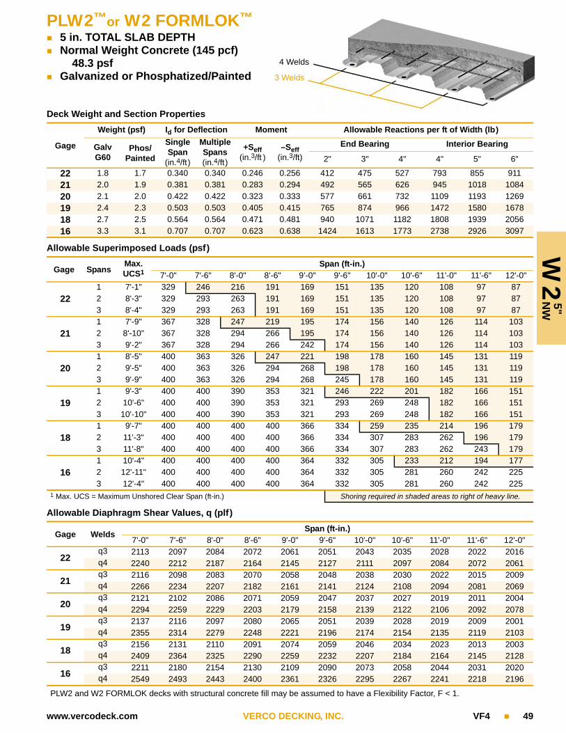
PLW2™or W2 FORMLOK™
5 in. TOTAL SLAB DEPTH Normal Weight Concrete (145 pcf)
48.3 psf Galvanized or Phosphatized/Painted
W2
5"
NW
4 Welds
3 Welds
www.vercodeck.com VERCO DECKING, INC. VF4 49
Deck Weight and Section Properties
Gage
Weight (psf) Id for Deflection Moment Allowable Reactions per ft of Width (lb)
Galv G60
Phos/Painted
Single Span
(in.4/ft)
Multiple Spans(in.4/ft)
+Seff(in.3/ft )
–Seff(in.3/ft)
End Bearing Interior Bearing
2" 3" 4" 4" 5" 6"
22 1.8 1.7 0.340 0.340 0.246 0.256 412 475 527 793 855 911
21 2.0 1.9 0.381 0.381 0.283 0.294 492 565 626 945 1018 1084
20 2.1 2.0 0.422 0.422 0.323 0.333 577 661 732 1109 1193 1269
19 2.4 2.3 0.503 0.503 0.405 0.415 765 874 966 1472 1580 1678
18 2.7 2.5 0.564 0.564 0.471 0.481 940 1071 1182 1808 1939 2056
16 3.3 3.1 0.707 0.707 0.623 0.638 1424 1613 1773 2738 2926 3097
Allowable Superimposed Loads (psf)
Gage SpansMax.UCS1
Span (ft-in.)7'-0" 7'-6" 8'-0" 8’-6" 9’-0" 9'-6" 10'-0" 10'-6" 11'-0" 11'-6" 12'-0"
221 7'-1" 329 246 216 191 169 151 135 120 108 97 872 8'-3" 329 293 263 191 169 151 135 120 108 97 873 8'-4" 329 293 263 191 169 151 135 120 108 97 87
211 7'-9" 367 328 247 219 195 174 156 140 126 114 1032 8'-10" 367 328 294 266 195 174 156 140 126 114 1033 9'-2" 367 328 294 266 242 174 156 140 126 114 103
201 8'-5" 400 363 326 247 221 198 178 160 145 131 1192 9'-5" 400 363 326 294 268 198 178 160 145 131 1193 9'-9" 400 363 326 294 268 245 178 160 145 131 119
191 9'-3" 400 400 390 353 321 246 222 201 182 166 1512 10'-6" 400 400 390 353 321 293 269 248 182 166 1513 10'-10" 400 400 390 353 321 293 269 248 182 166 151
181 9'-7" 400 400 400 400 366 334 259 235 214 196 1792 11'-3" 400 400 400 400 366 334 307 283 262 196 1793 11'-8" 400 400 400 400 366 334 307 283 262 243 179
161 10'-4" 400 400 400 400 364 332 305 233 212 194 1772 12'-11" 400 400 400 400 364 332 305 281 260 242 2253 12'-4" 400 400 400 400 364 332 305 281 260 242 225
1 Max. UCS = Maximum Unshored Clear Span (ft-in.) Shoring required in shaded areas to right of heavy line.
Allowable Diaphragm Shear Values, q (plf)
Gage WeldsSpan (ft-in.)
7'-0" 7'-6" 8'-0" 8'-6" 9'-0" 9'-6" 10'-0" 10'-6" 11'-0" 11'-6" 12'-0"
22q3 2113 2097 2084 2072 2061 2051 2043 2035 2028 2022 2016q4 2240 2212 2187 2164 2145 2127 2111 2097 2084 2072 2061
21q3 2116 2098 2083 2070 2058 2048 2038 2030 2022 2015 2009q4 2266 2234 2207 2182 2161 2141 2124 2108 2094 2081 2069
20q3 2121 2102 2086 2071 2059 2047 2037 2027 2019 2011 2004q4 2294 2259 2229 2203 2179 2158 2139 2122 2106 2092 2078
19q3 2137 2116 2097 2080 2065 2051 2039 2028 2019 2009 2001q4 2355 2314 2279 2248 2221 2196 2174 2154 2135 2119 2103
18q3 2156 2131 2110 2091 2074 2059 2046 2034 2023 2013 2003q4 2409 2364 2325 2290 2259 2232 2207 2184 2164 2145 2128
16q3 2211 2180 2154 2130 2109 2090 2073 2058 2044 2031 2020q4 2549 2493 2443 2400 2361 2326 2295 2267 2241 2218 2196
PLW2 and W2 FORMLOK decks with structural concrete fill may be assumed to have a Flexibility Factor, F < 1.
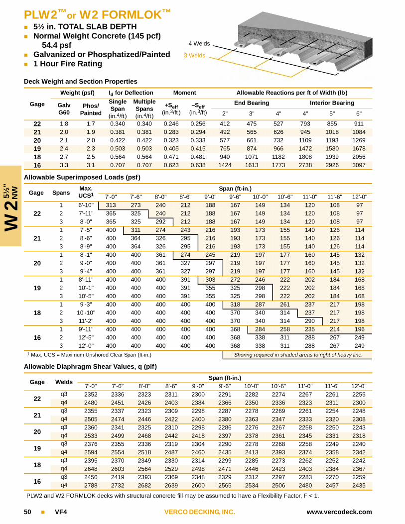
W2 5
½"
NW
PLW2™or W2 FORMLOK™
5½ in. TOTAL SLAB DEPTH Normal Weight Concrete (145 pcf)
54.4 psf Galvanized or Phosphatized/Painted 1 Hour Fire Rating
4 Welds
3 Welds
50 VF4 VERCO DECKING, INC. www.vercodeck.com
Deck Weight and Section Properties
Gage
Weight (psf) Id for Deflection Moment Allowable Reactions per ft of Width (lb)
Galv G60
Phos/Painted
Single Span
(in.4/ft)
Multiple Spans(in.4/ft)
+Seff(in.3/ft )
–Seff(in.3/ft)
End Bearing Interior Bearing
2" 3" 4" 4" 5" 6"
22 1.8 1.7 0.340 0.340 0.246 0.256 412 475 527 793 855 911
21 2.0 1.9 0.381 0.381 0.283 0.294 492 565 626 945 1018 1084
20 2.1 2.0 0.422 0.422 0.323 0.333 577 661 732 1109 1193 1269
19 2.4 2.3 0.503 0.503 0.405 0.415 765 874 966 1472 1580 1678
18 2.7 2.5 0.564 0.564 0.471 0.481 940 1071 1182 1808 1939 2056
16 3.3 3.1 0.707 0.707 0.623 0.638 1424 1613 1773 2738 2926 3097
Allowable Superimposed Loads (psf)
Gage SpansMax.UCS1
Span (ft-in.)7'-0" 7'-6" 8'-0" 8’-6" 9’-0" 9'-6" 10'-0" 10'-6" 11'-0" 11'-6" 12'-0"
221 6'-10" 313 273 240 212 188 167 149 134 120 108 972 7'-11" 365 325 240 212 188 167 149 134 120 108 973 8'-0" 365 325 292 212 188 167 149 134 120 108 97
211 7'-5" 400 311 274 243 216 193 173 155 140 126 1142 8'-6" 400 364 326 295 216 193 173 155 140 126 1143 8'-9" 400 364 326 295 216 193 173 155 140 126 114
201 8'-1" 400 400 361 274 245 219 197 177 160 145 1322 9'-0" 400 400 361 327 297 219 197 177 160 145 1323 9'-4" 400 400 361 327 297 219 197 177 160 145 132
191 8'-11" 400 400 400 391 303 272 246 222 202 184 1682 10'-1" 400 400 400 391 355 325 298 222 202 184 1683 10'-5" 400 400 400 391 355 325 298 222 202 184 168
181 9'-3" 400 400 400 400 400 318 287 261 237 217 1982 10'-10" 400 400 400 400 400 370 340 314 237 217 1983 11'-2" 400 400 400 400 400 370 340 314 290 217 198
161 9'-11" 400 400 400 400 400 368 284 258 235 214 1962 12'-5" 400 400 400 400 400 368 338 311 288 267 2493 12'-0" 400 400 400 400 400 368 338 311 288 267 249
1 Max. UCS = Maximum Unshored Clear Span (ft-in.) Shoring required in shaded areas to right of heavy line.
Allowable Diaphragm Shear Values, q (plf)
Gage WeldsSpan (ft-in.)
7'-0" 7'-6" 8'-0" 8'-6" 9'-0" 9'-6" 10'-0" 10'-6" 11'-0" 11'-6" 12'-0"
22q3 2352 2336 2323 2311 2300 2291 2282 2274 2267 2261 2255q4 2480 2451 2426 2403 2384 2366 2350 2336 2323 2311 2300
21q3 2355 2337 2323 2309 2298 2287 2278 2269 2261 2254 2248q4 2505 2474 2446 2422 2400 2380 2363 2347 2333 2320 2308
20q3 2360 2341 2325 2310 2298 2286 2276 2267 2258 2250 2243q4 2533 2499 2468 2442 2418 2397 2378 2361 2345 2331 2318
19q3 2376 2355 2336 2319 2304 2290 2278 2268 2258 2249 2240q4 2594 2554 2518 2487 2460 2435 2413 2393 2374 2358 2342
18q3 2395 2370 2349 2330 2314 2299 2285 2273 2262 2252 2242q4 2648 2603 2564 2529 2498 2471 2446 2423 2403 2384 2367
16q3 2450 2419 2393 2369 2348 2329 2312 2297 2283 2270 2259q4 2788 2732 2682 2639 2600 2565 2534 2506 2480 2457 2435
PLW2 and W2 FORMLOK decks with structural concrete fill may be assumed to have a Flexibility Factor, F < 1.

PLW2™or W2 FORMLOK™
6½ in. TOTAL SLAB DEPTH Normal Weight Concrete (145 pcf)
66.5 psf Galvanized or Phosphatized/Painted 2 Hour Fire Rating
W2
6½
"N
W
4 Welds
3 Welds
www.vercodeck.com VERCO DECKING, INC. VF4 51
Deck Weight and Section Properties
Gage
Weight (psf) Id for Deflection Moment Allowable Reactions per ft of Width (lb)
Galv G60
Phos/Painted
Single Span
(in.4/ft)
Multiple Spans(in.4/ft)
+Seff(in.3/ft )
–Seff(in.3/ft)
End Bearing Interior Bearing
2" 3" 4" 4" 5" 6"
22 1.8 1.7 0.340 0.340 0.246 0.256 412 475 527 793 855 911
21 2.0 1.9 0.381 0.381 0.283 0.294 492 565 626 945 1018 1084
20 2.1 2.0 0.422 0.422 0.323 0.333 577 661 732 1109 1193 1269
19 2.4 2.3 0.503 0.503 0.405 0.415 765 874 966 1472 1580 1678
18 2.7 2.5 0.564 0.564 0.471 0.481 940 1071 1182 1808 1939 2056
16 3.3 3.1 0.707 0.707 0.623 0.638 1424 1613 1773 2738 2926 3097
Allowable Superimposed Loads (psf)
Gage SpansMax.UCS1
Span (ft-in.)7'-0" 7'-6" 8'-0" 8’-6" 9’-0" 9'-6" 10'-0" 10'-6" 11'-0" 11'-6" 12'-0"
221 6'-4" 377 329 290 256 227 202 180 161 145 130 1172 7'-5" 400 329 290 256 227 202 180 161 145 130 1173 7'-6" 400 392 290 256 227 202 180 161 145 130 117
211 6'-11" 400 375 331 293 261 233 209 187 169 152 1382 7'-11" 400 400 331 293 261 233 209 187 169 152 1383 8'-2" 400 400 393 293 261 233 209 187 169 152 138
201 7'-6" 400 400 372 331 295 264 237 214 193 175 1592 8'-5" 400 400 400 331 295 264 237 214 193 175 1593 8'-9" 400 400 400 393 295 264 237 214 193 175 159
191 8'-5" 400 400 400 400 365 328 296 268 243 221 2022 9'-5" 400 400 400 400 400 328 296 268 243 221 2023 9'-9" 400 400 400 400 400 391 296 268 243 221 202
181 8'-9" 400 400 400 400 400 382 346 314 286 261 2392 10'-1" 400 400 400 400 400 400 400 314 286 261 2393 10'-5" 400 400 400 400 400 400 400 314 286 261 239
161 9'-4" 400 400 400 400 400 378 342 310 282 258 2362 11'-7" 400 400 400 400 400 400 400 374 346 321 2363 11'-6" 400 400 400 400 400 400 400 374 346 321 236
1 Max. UCS = Maximum Unshored Clear Span (ft-in.) Shoring required in shaded areas to right of heavy line.
Allowable Diaphragm Shear Values, q (plf)
Gage WeldsSpan (ft-in.)
7'-0" 7'-6" 8'-0" 8'-6" 9'-0" 9'-6" 10'-0" 10'-6" 11'-0" 11'-6" 12'-0"
22q3 2830 2815 2801 2789 2778 2769 2760 2752 2745 2739 2733q4 2958 2929 2904 2882 2862 2844 2828 2814 2801 2789 2778
21q3 2833 2816 2801 2787 2776 2765 2756 2747 2739 2732 2726q4 2983 2952 2924 2900 2878 2859 2841 2825 2811 2798 2786
20q3 2838 2819 2803 2789 2776 2764 2754 2745 2736 2728 2721q4 3011 2977 2947 2920 2896 2875 2856 2839 2823 2809 2796
19q3 2855 2833 2814 2797 2782 2769 2757 2746 2736 2727 2718q4 3072 3032 2997 2966 2938 2913 2891 2871 2853 2836 2821
18q3 2873 2849 2827 2808 2792 2777 2763 2751 2740 2730 2721q4 3126 3081 3042 3007 2976 2949 2924 2901 2881 2862 2845
16q3 2928 2898 2871 2847 2826 2807 2790 2775 2761 2749 2737q4 3267 3210 3161 3117 3078 3044 3012 2984 2958 2935 2914
PLW2 and W2 FORMLOK decks with structural concrete fill may be assumed to have a Flexibility Factor, F < 1.

W2 4
"LW
PLW2™or W2 FORMLOK™
4 in. TOTAL SLAB DEPTH Light Weight Concrete (110 pcf)
27.5 psf Galvanized or Phosphatized/Painted
4 Welds
3 Welds
52 VF4 VERCO DECKING, INC. www.vercodeck.com
Deck Weight and Section Properties
Gage
Weight (psf) Id for Deflection Moment Allowable Reactions per ft of Width (lb)
Galv G60
Phos/Painted
Single Span
(in.4/ft)
Multiple Spans(in.4/ft)
+Seff(in.3/ft )
–Seff(in.3/ft)
End Bearing Interior Bearing
2" 3" 4" 4" 5" 6"
22 1.8 1.7 0.340 0.340 0.246 0.256 412 475 527 793 855 911
21 2.0 1.9 0.381 0.381 0.283 0.294 492 565 626 945 1018 1084
20 2.1 2.0 0.422 0.422 0.323 0.333 577 661 732 1109 1193 1269
19 2.4 2.3 0.503 0.503 0.405 0.415 765 874 966 1472 1580 1678
18 2.7 2.5 0.564 0.564 0.471 0.481 940 1071 1182 1808 1939 2056
16 3.3 3.1 0.707 0.707 0.623 0.638 1424 1613 1773 2738 2926 3097
Allowable Superimposed Loads (psf)
Gage SpansMax.UCS1
Span (ft-in.)7'-0" 7'-6" 8'-0" 8’-6" 9’-0" 9'-6" 10'-0" 10'-6" 11'-0" 11'-6" 12'-0"
221 8'-6" 261 232 209 189 144 129 116 105 95 86 782 9'-10" 261 232 209 189 171 157 116 105 95 86 783 10'-1" 261 232 209 189 171 157 144 105 95 86 78
211 9'-4" 292 260 234 211 192 147 133 120 109 100 902 10'-6" 292 260 234 211 192 175 156 134 109 100 903 10'-11" 292 260 234 211 192 175 156 134 109 100 90
201 10'-2" 324 288 259 234 213 188 161 136 121 106 932 11'-2" 324 288 259 234 213 188 161 139 121 106 933 11'-7" 324 288 259 234 213 188 161 139 121 106 93
191 10'-11" 389 347 308 270 237 201 173 149 130 113 1002 12'-5" 389 347 308 270 237 201 173 149 130 113 1003 12'-11" 389 347 308 270 237 201 173 149 130 113 100
181 11'-4" 400 376 328 288 249 211 181 157 136 119 1052 13'-5" 400 376 328 288 249 211 181 157 136 119 1053 13'-3" 400 376 328 288 249 211 181 157 136 119 105
161 11'-11" 400 396 356 322 276 235 201 174 151 132 1162 14'-10" 400 396 356 322 276 235 201 174 151 132 1163 13'-11" 400 396 356 322 276 235 201 174 151 132 116
1 Max. UCS = Maximum Unshored Clear Span (ft-in.) Shoring required in shaded areas to right of heavy line.
Allowable Diaphragm Shear Values, q (plf)
Gage WeldsSpan (ft-in.)
7'-0" 7'-6" 8'-0" 8'-6" 9'-0" 9'-6" 10'-0" 10'-6" 11'-0" 11'-6" 12'-0"
22q3 1310 1295 1281 1269 1258 1249 1240 1232 1225 1219 1213q4 1438 1409 1384 1362 1342 1324 1309 1294 1281 1269 1258
21q3 1313 1296 1281 1268 1256 1245 1236 1227 1220 1212 1206q4 1463 1432 1404 1380 1358 1339 1321 1305 1291 1278 1266
20q3 1318 1300 1283 1269 1256 1244 1234 1225 1216 1209 1201q4 1491 1457 1427 1400 1376 1355 1336 1319 1303 1289 1276
19q3 1335 1313 1294 1277 1262 1249 1237 1226 1216 1207 1199q4 1552 1512 1477 1446 1418 1393 1371 1351 1333 1316 1301
18q3 1353 1329 1307 1289 1272 1257 1243 1231 1220 1210 1201q4 1607 1562 1522 1487 1457 1429 1404 1382 1361 1342 1325
16q3 1408 1378 1351 1327 1306 1287 1271 1255 1241 1229 1217q4 1747 1690 1641 1597 1558 1524 1493 1464 1439 1415 1394
PLW2 and W2 FORMLOK decks with structural concrete fill may be assumed to have a Flexibility Factor, F < 1.

PLW2™or W2 FORMLOK™
4½ in. TOTAL SLAB DEPTH Light Weight Concrete (110 pcf)
32.1 psf Galvanized or Phosphatized/Painted 1 Hour Fire Rating
W2
4½
"LW
www.vercodeck.com VERCO DECKING, INC. VF4 53
4 Welds
3 Welds
Deck Weight and Section Properties
Gage
Weight (psf) Id for Deflection Moment Allowable Reactions per ft of Width (lb)
Galv G60
Phos/Painted
Single Span
(in.4/ft)
Multiple Spans(in.4/ft)
+Seff(in.3/ft )
–Seff(in.3/ft)
End Bearing Interior Bearing
2" 3" 4" 4" 5" 6"
22 1.8 1.7 0.340 0.340 0.246 0.256 412 475 527 793 855 911
21 2.0 1.9 0.381 0.381 0.283 0.294 492 565 626 945 1018 1084
20 2.1 2.0 0.422 0.422 0.323 0.333 577 661 732 1109 1193 1269
19 2.4 2.3 0.503 0.503 0.405 0.415 765 874 966 1472 1580 1678
18 2.7 2.5 0.564 0.564 0.471 0.481 940 1071 1182 1808 1939 2056
16 3.3 3.1 0.707 0.707 0.623 0.638 1424 1613 1773 2738 2926 3097
Allowable Superimposed Loads (psf)
Gage SpansMax.UCS1
Span (ft-in.)7'-0" 7'-6" 8'-0" 8’-6" 9’-0" 9'-6" 10'-0" 10'-6" 11'-0" 11'-6" 12'-0"
221 8'-1" 294 262 235 181 161 145 130 118 106 97 882 9'-5" 294 262 235 213 193 145 130 118 106 97 883 9'-7" 294 262 235 213 193 177 130 118 106 97 88
211 8'-11" 329 293 263 238 184 166 149 135 123 112 1022 10'-1" 329 293 263 238 216 198 181 135 123 112 1023 10'-5" 329 293 263 238 216 198 181 135 123 112 102
201 9'-8" 364 324 291 263 239 219 169 153 139 127 1162 10'-9" 364 324 291 263 239 219 201 185 139 127 1163 11'-1" 364 324 291 263 239 219 201 185 167 127 116
191 10'-6" 400 389 349 316 287 262 238 205 173 156 1382 11'-11" 400 389 349 316 287 262 238 205 179 156 1383 12'-4" 400 389 349 316 287 262 238 205 179 156 138
181 10'-10" 400 400 399 361 327 291 250 216 188 164 1442 12'-10" 400 400 399 361 327 291 250 216 188 164 1443 12'-10" 400 400 399 361 327 291 250 216 188 164 144
161 11'-7" 400 400 397 359 327 298 274 238 207 182 1602 14'-5" 400 400 397 359 327 298 274 238 207 182 1603 13'-6" 400 400 397 359 327 298 274 238 207 182 160
1 Max. UCS = Maximum Unshored Clear Span (ft-in.) Shoring required in shaded areas to right of heavy line.
Allowable Diaphragm Shear Values, q (plf)
Gage WeldsSpan (ft-in.)
7'-0" 7'-6" 8'-0" 8'-6" 9'-0" 9'-6" 10'-0" 10'-6" 11'-0" 11'-6" 12'-0"
22q3 1468 1453 1439 1427 1416 1407 1398 1390 1383 1377 1371q4 1596 1567 1542 1520 1500 1482 1467 1452 1439 1427 1416
21q3 1471 1454 1439 1426 1414 1403 1394 1385 1378 1370 1364q4 1621 1590 1562 1538 1516 1497 1479 1463 1449 1436 1424
20q3 1476 1458 1441 1427 1414 1402 1392 1383 1374 1367 1359q4 1649 1615 1585 1558 1534 1513 1494 1477 1461 1447 1434
19q3 1493 1471 1452 1435 1420 1407 1395 1384 1374 1365 1357q4 1710 1670 1635 1604 1576 1551 1529 1509 1491 1474 1459
18q3 1511 1487 1465 1447 1430 1415 1401 1389 1378 1368 1359q4 1765 1720 1680 1645 1615 1587 1562 1540 1519 1500 1483
16q3 1566 1536 1509 1485 1464 1445 1429 1413 1399 1387 1375q4 1905 1848 1799 1755 1716 1682 1650 1622 1597 1573 1552
PLW2 and W2 FORMLOK decks with structural concrete fill may be assumed to have a Flexibility Factor, F < 1.

W2 5
¼"
LW
54 VF4 VERCO DECKING, INC. www.vercodeck.com
PLW2™or W2 FORMLOK™
5¼ in. TOTAL SLAB DEPTH Light Weight Concrete (110 pcf)
39.0 psf Galvanized or Phosphatized/Painted 2 Hour Fire Rating
4 Welds
3 Welds
Deck Weight and Section Properties
Gage
Weight (psf) Id for Deflection Moment Allowable Reactions per ft of Width (lb)
Galv G60
Phos/Painted
Single Span
(in.4/ft)
Multiple Spans(in.4/ft)
+Seff(in.3/ft )
–Seff(in.3/ft)
End Bearing Interior Bearing
2" 3" 4" 4" 5" 6"
22 1.8 1.7 0.340 0.340 0.246 0.256 412 475 527 793 855 911
21 2.0 1.9 0.381 0.381 0.283 0.294 492 565 626 945 1018 1084
20 2.1 2.0 0.422 0.422 0.323 0.333 577 661 732 1109 1193 1269
19 2.4 2.3 0.503 0.503 0.405 0.415 765 874 966 1472 1580 1678
18 2.7 2.5 0.564 0.564 0.471 0.481 940 1071 1182 1808 1939 2056
16 3.3 3.1 0.707 0.707 0.623 0.638 1424 1613 1773 2738 2926 3097
Allowable Superimposed Loads (psf)
Gage SpansMax.UCS1
Span (ft-in.)7'-0" 7'-6" 8'-0" 8’-6" 9’-0" 9'-6" 10'-0" 10'-6" 11'-0" 11'-6" 12'-0"
221 7'-8" 347 309 240 213 190 171 154 139 125 114 1032 8'-11" 347 309 277 251 190 171 154 139 125 114 1033 9'-0" 347 309 277 251 228 171 154 139 125 114 103
211 8'-5" 388 345 310 242 217 195 176 159 145 132 1202 9'-6" 388 345 310 280 255 233 176 159 145 132 1203 9'-10" 388 345 310 280 255 233 176 159 145 132 120
201 9'-1" 400 382 343 310 282 220 199 180 164 150 1372 10'-2" 400 382 343 310 282 258 237 180 164 150 1373 10'-6" 400 382 343 310 282 258 237 218 164 150 137
191 9'-11" 400 400 400 372 338 309 245 223 204 186 1712 11'-3" 400 400 400 372 338 309 283 261 242 186 1713 11'-8" 400 400 400 372 338 309 283 261 242 225 171
181 10'-3" 400 400 400 400 385 352 323 260 237 218 2002 12'-2" 400 400 400 400 385 352 323 298 276 251 2213 12'-4" 400 400 400 400 385 352 323 298 276 251 221
161 11'-0" 400 400 400 400 383 350 321 296 274 215 1982 13'-10" 400 400 400 400 383 350 321 296 274 254 2373 13'-0" 400 400 400 400 383 350 321 296 274 254 237
1 Max. UCS = Maximum Unshored Clear Span (ft-in.) Shoring required in shaded areas to right of heavy line.
Allowable Diaphragm Shear Values, q (plf)
Gage WeldsSpan (ft-in.)
7'-0" 7'-6" 8'-0" 8'-6" 9'-0" 9'-6" 10'-0" 10'-6" 11'-0" 11'-6" 12'-0"
22q3 1705 1690 1676 1664 1653 1644 1635 1627 1620 1614 1608q4 1833 1804 1779 1757 1737 1719 1703 1689 1676 1664 1653
21q3 1708 1691 1676 1663 1651 1640 1631 1622 1614 1607 1601q4 1858 1827 1799 1775 1753 1734 1716 1700 1686 1673 1661
20q3 1713 1694 1678 1664 1651 1639 1629 1620 1611 1604 1596q4 1886 1852 1822 1795 1771 1750 1731 1714 1698 1684 1671
19q3 1730 1708 1689 1672 1657 1644 1632 1621 1611 1602 1594q4 1947 1907 1872 1841 1813 1788 1766 1746 1728 1711 1696
18q3 1748 1724 1702 1684 1667 1652 1638 1626 1615 1605 1596q4 2002 1957 1917 1882 1852 1824 1799 1776 1756 1737 1720
16q3 1803 1773 1746 1722 1701 1682 1666 1650 1636 1624 1612q4 2142 2085 2036 1992 1953 1919 1887 1859 1834 1810 1789
PLW2 and W2 FORMLOK decks with structural concrete fill may be assumed to have a Flexibility Factor, F < 1.

PLW2™or W2 FORMLOK™
6¼ in. TOTAL SLAB DEPTH Light Weight Concrete (110 pcf)
48.1 psf Galvanized or Phosphatized/Painted 3 Hour Fire Rating
4 Welds
3 Welds
www.vercodeck.com VERCO DECKING, INC. VF4 55
W2
6¼
"LW
Deck Weight and Section Properties
Gage
Weight (psf) Id for Deflection Moment Allowable Reactions per ft of Width (lb)
Galv G60
Phos/Painted
Single Span
(in.4/ft)
Multiple Spans(in.4/ft)
+Seff(in.3/ft )
–Seff(in.3/ft)
End Bearing Interior Bearing
2" 3" 4" 4" 5" 6"
22 1.8 1.7 0.340 0.340 0.246 0.256 412 475 527 793 855 911
21 2.0 1.9 0.381 0.381 0.283 0.294 492 565 626 945 1018 1084
20 2.1 2.0 0.422 0.422 0.323 0.333 577 661 732 1109 1193 1269
19 2.4 2.3 0.503 0.503 0.405 0.415 765 874 966 1472 1580 1678
18 2.7 2.5 0.564 0.564 0.471 0.481 940 1071 1182 1808 1939 2056
16 3.3 3.1 0.707 0.707 0.623 0.638 1424 1613 1773 2738 2926 3097
Allowable Superimposed Loads (psf)
Gage SpansMax.UCS1
Span (ft-in.)7'-0" 7'-6" 8'-0" 8’-6" 9’-0" 9'-6" 10'-0" 10'-6" 11'-0" 11'-6" 12'-0"
221 7'-2" 400 329 291 259 231 207 187 168 152 138 1262 8'-4" 400 375 337 259 231 207 187 168 152 138 1263 8'-5" 400 375 337 259 231 207 187 168 152 138 126
211 7'-10" 400 400 331 294 263 237 214 193 176 160 1462 8'-11" 400 400 376 340 263 237 214 193 176 160 1463 9'-3" 400 400 376 340 309 237 214 193 176 160 146
201 8'-6" 400 400 400 376 296 267 241 219 199 182 1662 9'-6" 400 400 400 376 342 313 241 219 199 182 1663 9'-10" 400 400 400 376 342 313 241 219 199 182 166
191 9'-4" 400 400 400 400 400 328 297 270 247 226 2072 10'-7" 400 400 400 400 400 374 343 317 247 226 2073 10'-11" 400 400 400 400 400 374 343 317 247 226 207
181 9'-8" 400 400 400 400 400 400 345 315 288 264 2432 11'-4" 400 400 400 400 400 400 392 361 334 264 2433 11'-9" 400 400 400 400 400 400 392 361 334 310 243
161 10'-5" 400 400 400 400 400 400 388 311 284 261 2402 13'-0" 400 400 400 400 400 400 388 358 331 308 2863 12'-5" 400 400 400 400 400 400 388 358 331 308 286
1 Max. UCS = Maximum Unshored Clear Span (ft-in.) Shoring required in shaded areas to right of heavy line.
Allowable Diaphragm Shear Values, q (plf)
Gage WeldsSpan (ft-in.)
7'-0" 7'-6" 8'-0" 8'-6" 9'-0" 9'-6" 10'-0" 10'-6" 11'-0" 11'-6" 12'-0"
22q3 2021 2006 1992 1980 1969 1960 1951 1943 1936 1930 1924q4 2149 2120 2095 2073 2053 2035 2019 2005 1992 1980 1969
21q3 2024 2007 1992 1978 1967 1956 1947 1938 1930 1923 1917q4 2174 2143 2115 2091 2069 2050 2032 2016 2002 1989 1977
20q3 2029 2010 1994 1980 1967 1955 1945 1936 1927 1919 1912q4 2202 2168 2138 2111 2087 2066 2047 2030 2014 2000 1987
19q3 2046 2024 2005 1988 1973 1960 1948 1937 1927 1918 1909q4 2263 2223 2188 2157 2129 2104 2082 2062 2044 2027 2012
18q3 2064 2040 2018 1999 1983 1968 1954 1942 1931 1921 1912q4 2317 2272 2233 2198 2167 2140 2115 2092 2072 2053 2036
16q3 2119 2089 2062 2038 2017 1998 1981 1966 1952 1940 1928q4 2458 2401 2352 2308 2269 2235 2203 2175 2149 2126 2105
PLW2 and W2 FORMLOK decks with structural concrete fill may be assumed to have a Flexibility Factor, F < 1.
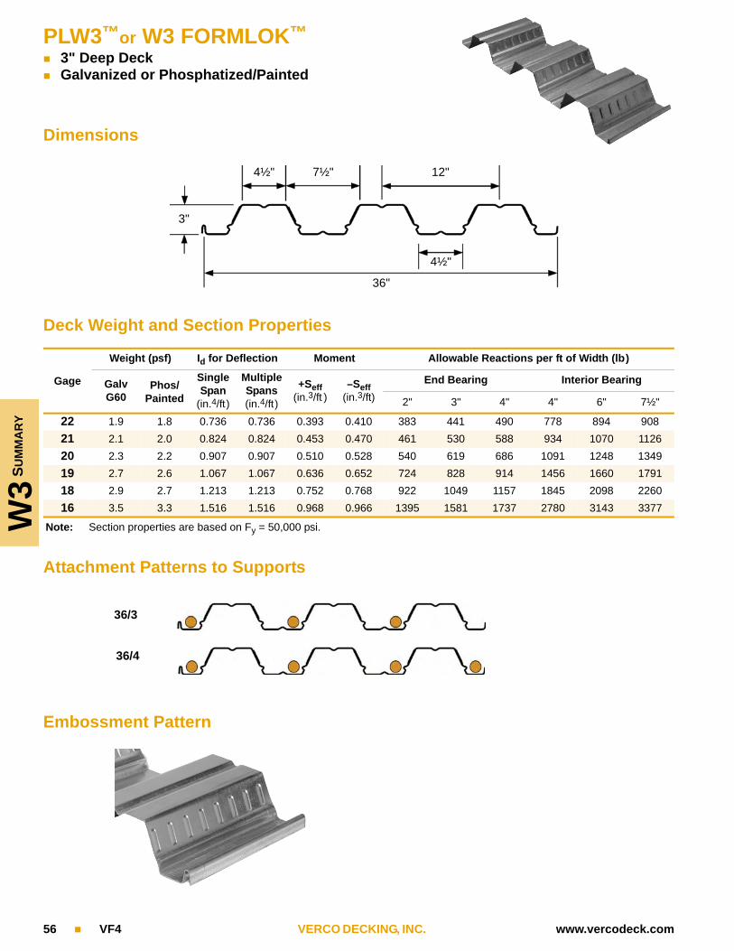
W3
SU
MM
AR
Y
PLW3™or W3 FORMLOK™
3" Deep Deck Galvanized or Phosphatized/Painted
56 VF4 VERCO DECKING, INC. www.vercodeck.com
Dimensions
Deck Weight and Section Properties
Attachment Patterns to Supports
Embossment Pattern
Gage
Weight (psf) Id for Deflection Moment Allowable Reactions per ft of Width (lb)
Galv G60
Phos/Painted
Single Span
(in.4/ft)
Multiple Spans(in.4/ft)
+Seff(in.3/ft )
–Seff(in.3/ft)
End Bearing Interior Bearing
2" 3" 4" 4" 6" 7½"
22 1.9 1.8 0.736 0.736 0.393 0.410 383 441 490 778 894 908
21 2.1 2.0 0.824 0.824 0.453 0.470 461 530 588 934 1070 1126
20 2.3 2.2 0.907 0.907 0.510 0.528 540 619 686 1091 1248 1349
19 2.7 2.6 1.067 1.067 0.636 0.652 724 828 914 1456 1660 1791
18 2.9 2.7 1.213 1.213 0.752 0.768 922 1049 1157 1845 2098 2260
16 3.5 3.3 1.516 1.516 0.968 0.966 1395 1581 1737 2780 3143 3377
Note: Section properties are based on Fy = 50,000 psi.
4½" 7½" 12"
4½"
36"
3"
36/3
36/4

PLW3™or W3 FORMLOK™
5 in. TOTAL SLAB DEPTH Normal Weight Concrete (145 pcf)
42.3 psf Galvanized or Phosphatized/Painted
W3
5"
NW
4 Welds
3 Welds
www.vercodeck.com VERCO DECKING, INC. VF4 57
Deck Weight and Section Properties
Gage
Weight (psf) Id for Deflection Moment Allowable Reactions per ft of Width (lb)
Galv G60
Phos/Painted
Single Span
(in.4/ft)
Multiple Spans(in.4/ft)
+Seff(in.3/ft )
–Seff(in.3/ft)
End Bearing Interior Bearing
2" 3" 4" 4" 6" 7½"
22 1.9 1.8 0.736 0.736 0.393 0.410 383 441 490 778 894 908
21 2.1 2.0 0.824 0.824 0.453 0.470 461 530 588 934 1070 112620 2.3 2.2 0.907 0.907 0.510 0.528 540 619 686 1091 1248 134919 2.7 2.6 1.067 1.067 0.636 0.652 724 828 914 1456 1660 1791
18 2.9 2.7 1.213 1.213 0.752 0.768 922 1049 1157 1845 2098 226016 3.5 3.3 1.516 1.516 0.968 0.966 1395 1581 1737 2780 3143 3377
Allowable Superimposed Loads (psf)
Gage SpansMax.UCS1
Span (ft-in.)
8'-0" 8'-6" 9'-0" 9'-6" 10'-0" 10'-6" 11'-0" 11'-6" 12'-0" 12'-6" 13-0" 13'-6" 14'-0" 14'-6" 15'-0"
221 10'-0" 254 229 208 190 175 120 108 97 88 79 72 65 58 53 482 10'-7" 254 229 208 190 175 161 108 97 88 79 72 65 58 53 483 10'-7" 254 229 208 190 175 161 108 97 88 79 72 65 58 53 48
211 10'-11" 274 248 225 206 189 174 120 108 98 89 81 73 66 60 552 11'-8" 274 248 225 206 189 174 161 150 98 89 81 73 66 60 553 12'-1" 274 248 225 206 189 174 161 150 140 89 81 73 66 60 55
201 11'-7" 294 265 241 220 202 187 173 160 108 98 89 81 74 67 612 12'-4" 294 265 241 220 202 187 173 160 149 98 89 81 74 67 613 12'-10" 294 265 241 220 202 187 173 160 149 140 89 81 74 67 61
191 12'-1" 333 301 274 250 230 212 191 172 155 116 106 97 89 82 752 13'-9" 333 301 274 250 230 212 191 172 155 140 126 115 89 82 753 14'-2" 333 301 274 250 230 212 191 172 155 140 126 115 104 82 75
181 12'-5" 370 334 304 278 255 232 208 187 169 134 122 112 103 95 882 14'-10" 370 334 304 278 255 232 208 187 169 153 139 126 115 104 883 14'-7" 370 334 304 278 255 232 208 187 169 153 139 126 115 104 88
161 13'-1" 400 400 365 333 299 268 241 217 197 178 162 143 132 122 1132 16'-4" 400 400 365 333 299 268 241 217 197 178 162 148 135 123 1133 15'-4" 400 400 365 333 299 268 241 217 197 178 162 148 135 123 113
1 Max. UCS = Maximum Unshored Clear Span (ft-in.) Shoring required in shaded areas to right of heavy line.
Allowable Allowable Diaphragm Shear Values, q (plf)
Gage WeldsSpan (ft-in.)
8'-0" 8'-6" 9'-0" 9'-6" 10'-0" 10'-6" 11'-0" 11'-6" 12'-0" 12'-6" 13'-0" 13'-6" 14'-0" 14'-6" 15'-0"
22q3 1606 1594 1583 1573 1565 1557 1550 1544 1538 1532 1527 1523 1518 1514 1511
q4 1708 1686 1666 1648 1633 1618 1605 1593 1583 1572 1563 1555 1547 1539 1532
21q3 1605 1592 1580 1570 1560 1552 1544 1537 1530 1524 1519 1514 1509 1505 1500
q4 1729 1704 1683 1663 1646 1630 1616 1602 1590 1579 1569 1560 1551 1543 1535
20q3 1608 1593 1580 1569 1559 1549 1541 1533 1526 1520 1513 1508 1503 1498 1493
q4 1750 1724 1700 1679 1660 1643 1627 1613 1600 1588 1577 1567 1557 1548 1540
19q3 1618 1602 1587 1573 1561 1550 1540 1531 1523 1515 1508 1502 1496 1490 1485
q4 1801 1770 1742 1718 1696 1675 1657 1640 1625 1611 1598 1586 1575 1565 1555
18q3 1634 1615 1598 1583 1569 1557 1546 1535 1526 1517 1509 1502 1495 1488 1482
q4 1854 1819 1787 1759 1734 1711 1690 1671 1654 1638 1623 1609 1597 1585 1574
16q3 1679 1655 1633 1614 1597 1582 1568 1555 1543 1532 1522 1513 1504 1496 1489
q4 1973 1929 1890 1855 1823 1795 1769 1745 1723 1703 1684 1667 1651 1637 1623
PLW3 and W3 FORMLOK decks with structural concrete fill may be assumed to have a Flexibility Factor, F < 1.

W3 5
½"
NW
58 VF4 VERCO DECKING, INC. www.vercodeck.com
PLW3™or W3 FORMLOK™
5½ in. TOTAL SLAB DEPTH Normal Weight Concrete (145 pcf)
48.3 psf Galvanized or Phosphatized/Painted
4 Welds
3 Welds
Deck Weight and Section Properties
Gage
Weight (psf) Id for Deflection Moment Allowable Reactions per ft of Width (lb)
Galv G60
Phos/Painted
Single Span
(in.4/ft)
Multiple Spans(in.4/ft)
+Seff(in.3/ft )
–Seff(in.3/ft)
End Bearing Interior Bearing
2" 3" 4" 4" 6" 7½"
22 1.9 1.8 0.736 0.736 0.393 0.410 383 441 490 778 894 90821 2.1 2.0 0.824 0.824 0.453 0.470 461 530 588 934 1070 1126
20 2.3 2.2 0.907 0.907 0.510 0.528 540 619 686 1091 1248 134919 2.7 2.6 1.067 1.067 0.636 0.652 724 828 914 1456 1660 179118 2.9 2.7 1.213 1.213 0.752 0.768 922 1049 1157 1845 2098 2260
16 3.5 3.3 1.516 1.516 0.968 0.966 1395 1581 1737 2780 3143 3377
Allowable Superimposed Loads (psf)
Gage SpansMax.UCS1
Span (ft-in.)
8'-0" 8'-6" 9'-0" 9'-6" 10'-0" 10'-6" 11'-0" 11'-6" 12'-0" 12'-6" 13-0" 13'-6" 14'-0" 14'-6" 15'-0"
221 9'-7" 278 251 228 209 145 130 117 105 95 85 77 70 63 57 512 9'-9" 278 251 228 209 145 130 117 105 95 85 77 70 63 57 513 9'-9" 278 251 228 209 145 130 117 105 95 85 77 70 63 57 51
211 10'-5" 300 271 247 225 207 144 130 117 106 96 87 79 71 65 592 11'-2" 300 271 247 225 207 191 177 117 106 96 87 79 71 65 593 11'-7" 300 271 247 225 207 191 177 164 106 96 87 79 71 65 59
201 11'-2" 321 290 264 241 221 204 189 128 116 106 96 87 79 72 662 11'-10" 321 290 264 241 221 204 189 175 116 106 96 87 79 72 663 12'-3" 321 290 264 241 221 204 189 175 163 106 96 87 79 72 66
191 11'-9" 363 328 298 273 250 231 214 198 138 125 115 105 96 88 802 13'-2" 363 328 298 273 250 231 214 198 185 173 162 105 96 88 803 13'-7" 363 328 298 273 250 231 214 198 185 173 162 152 96 88 80
181 12'-1" 400 364 331 302 277 256 237 220 205 144 132 121 111 102 942 14'-3" 400 364 331 302 277 256 237 220 205 191 179 168 158 102 943 14'-2" 400 364 331 302 277 256 237 220 205 191 179 168 158 102 94
161 12'-9" 400 400 395 361 332 306 283 263 245 223 166 153 141 131 1212 15'-11" 400 400 395 361 332 306 283 263 245 223 203 185 169 155 1423 14'-11" 400 400 395 361 332 306 283 263 245 223 203 185 169 155 121
1 Max. UCS = Maximum Unshored Clear Span (ft-in.) Shoring required in shaded areas to right of heavy line.
Allowable Diaphragm Shear Values, q (plf)
Gage WeldsSpan (ft-in.)
8'-0" 8'-6" 9'-0" 9'-6" 10'-0" 10'-6" 11'-0" 11'-6" 12'-0" 12'-6" 13'-0" 13'-6" 14'-0" 14'-6" 15'-0"
22q3 1845 1833 1822 1813 1804 1796 1789 1783 1777 1771 1766 1762 1757 1753 1750
q4 1947 1925 1905 1888 1872 1857 1844 1832 1822 1812 1802 1794 1786 1778 1772
21q3 1844 1831 1819 1809 1799 1791 1783 1776 1769 1763 1758 1753 1748 1744 1739
q4 1968 1943 1922 1902 1885 1869 1855 1842 1829 1818 1808 1799 1790 1782 1774
20q3 1847 1832 1819 1808 1798 1788 1780 1772 1765 1759 1753 1747 1742 1737 1733
q4 1989 1963 1939 1918 1899 1882 1866 1852 1839 1827 1816 1806 1796 1787 1779
19q3 1857 1841 1826 1812 1800 1789 1779 1770 1762 1754 1747 1741 1735 1729 1724
q4 2040 2009 1982 1957 1935 1915 1896 1880 1864 1850 1837 1825 1814 1804 1794
18q3 1873 1854 1837 1822 1808 1796 1785 1774 1765 1756 1748 1741 1734 1727 1721
q4 2093 2058 2027 1998 1973 1950 1929 1910 1893 1877 1862 1849 1836 1824 1813
16q3 1918 1894 1873 1853 1836 1821 1807 1794 1782 1771 1761 1752 1743 1735 1728
q4 2213 2168 2129 2094 2062 2034 2008 1984 1962 1942 1924 1906 1891 1876 1862
PLW3 and W3 FORMLOK decks with structural concrete fill may be assumed to have a Flexibility Factor, F < 1.

PLW3™or W3 FORMLOK™
6 in. TOTAL SLAB DEPTH Normal Weight Concrete (145 pcf)
54.4 psf Galvanized or Phosphatized/Painted
W3
6"
NW
4 Welds
3 Welds
www.vercodeck.com VERCO DECKING, INC. VF4 59
Deck Weight and Section Properties
Gage
Weight (psf) Id for Deflection Moment Allowable Reactions per ft of Width (lb)
Galv G60
Phos/Painted
Single Span
(in.4/ft)
Multiple Spans(in.4/ft)
+Seff(in.3/ft )
–Seff(in.3/ft)
End Bearing Interior Bearing
2" 3" 4" 4" 6" 7½"
22 1.9 1.8 0.736 0.736 0.393 0.410 383 441 490 778 894 90821 2.1 2.0 0.824 0.824 0.453 0.470 461 530 588 934 1070 112620 2.3 2.2 0.907 0.907 0.510 0.528 540 619 686 1091 1248 1349
19 2.7 2.6 1.067 1.067 0.636 0.652 724 828 914 1456 1660 179118 2.9 2.7 1.213 1.213 0.752 0.768 922 1049 1157 1845 2098 226016 3.5 3.3 1.516 1.516 0.968 0.966 1395 1581 1737 2780 3143 3377
Allowable Superimposed Loads (psf)
Gage SpansMax.UCS1
Span (ft-in.)
8'-0" 8'-6" 9'-0" 9'-6" 10'-0" 10'-6" 11'-0" 11'-6" 12'-0" 12'-6" 13-0" 13'-6" 14'-0" 14'-6" 15'-0"
221 9'-2" 304 274 250 176 158 141 127 114 103 93 83 75 68 61 552 9'-0" 304 274 250 176 158 141 127 114 103 93 83 75 68 61 553 9'-0" 304 274 250 176 158 141 127 114 103 93 83 75 68 61 55
211 10'-0" 328 296 269 246 226 157 141 127 115 104 94 85 77 70 632 10'-9" 328 296 269 246 226 208 141 127 115 104 94 85 77 70 633 11'-2" 328 296 269 246 226 208 193 127 115 104 94 85 77 70 63
201 10'-8" 350 317 288 263 241 223 154 139 126 114 104 94 86 78 712 11'-5" 350 317 288 263 241 223 206 139 126 114 104 94 86 78 713 11'-10" 350 317 288 263 241 223 206 191 126 114 104 94 86 78 71
191 11'-5" 396 358 325 297 273 252 233 164 149 136 124 113 104 95 872 12'-8" 396 358 325 297 273 252 233 216 201 188 124 113 104 95 873 13'-1" 396 358 325 297 273 252 233 216 201 188 176 113 104 95 87
181 11'-9" 400 396 360 329 302 278 258 239 170 156 142 131 120 110 1012 13'-8" 400 396 360 329 302 278 258 239 223 208 195 183 120 110 1013 13'-9" 400 396 360 329 302 278 258 239 223 208 195 183 120 110 101
161 12'-5" 400 400 400 392 360 332 307 285 266 195 179 165 152 141 1302 15'-4" 400 400 400 392 360 332 307 285 266 248 233 218 206 191 1763 14'-6" 400 400 400 392 360 332 307 285 266 248 233 218 206 191 130
1 Max. UCS = Maximum Unshored Clear Span (ft-in.) Shoring required in shaded areas to right of heavy line.
Allowable Diaphragm Shear Values, q (plf)
Gage WeldsSpan (ft-in.)
8'-0" 8'-6" 9'-0" 9'-6" 10'-0" 10'-6" 11'-0" 11'-6" 12'-0" 12'-6" 13'-0" 13'-6" 14'-0" 14'-6" 15'-0"
22q3 2084 2072 2061 2052 2043 2035 2028 2022 2016 2010 2005 2001 1997 1992 1989
q4 2186 2164 2144 2127 2111 2096 2083 2072 2061 2051 2041 2033 2025 2017 2077
21q3 2083 2070 2058 2048 2038 2030 2022 2015 2009 2003 1997 1992 1987 1983 1979
q4 2207 2182 2161 2141 2124 2108 2094 2081 2069 2058 2047 2038 2029 2021 2013
20q3 2086 2071 2059 2047 2037 2027 2019 2011 2004 1998 1992 1986 1981 1976 1972
q4 2229 2202 2178 2157 2138 2121 2105 2091 2078 2066 2055 2045 2035 2026 2018
19q3 2097 2080 2065 2051 2039 2028 2019 2009 2001 1994 1987 1980 1974 1968 1963
q4 2279 2248 2221 2196 2174 2154 2135 2119 2103 2089 2076 2064 2053 2043 2033
18q3 2112 2093 2076 2061 2047 2035 2024 2013 2004 1995 1987 1980 1973 1967 1961
q4 2332 2297 2266 2237 2212 2189 2169 2150 2132 2116 2101 2088 2075 2063 2052
16q3 2157 2133 2112 2093 2075 2060 2046 2033 2021 2010 2000 1991 1982 1974 1967
q4 2452 2407 2368 2333 2301 2273 2247 2223 2201 2181 2163 2145 2130 2115 2101
PLW3 and W3 FORMLOK decks with structural concrete fill may be assumed to have a Flexibility Factor, F < 1.

W3 6
½"
NW
60 VF4 VERCO DECKING, INC. www.vercodeck.com
PLW3™or W3 FORMLOK™
6½ in. TOTAL SLAB DEPTH Normal Weight Concrete (145 pcf)
60.4 psf Galvanized or Phosphatized/Painted 1 Hour Fire Rating
4 Welds
3 Welds
Deck Weight and Section Properties
Gage
Weight (psf) Id for Deflection Moment Allowable Reactions per ft of Width (lb)
Galv G60
Phos/Painted
Single Span
(in.4/ft)
Multiple Spans(in.4/ft)
+Seff(in.3/ft )
–Seff(in.3/ft)
End Bearing Interior Bearing
2" 3" 4" 4" 6" 7½"
22 1.9 1.8 0.736 0.736 0.393 0.410 383 441 490 778 894 90821 2.1 2.0 0.824 0.824 0.453 0.470 461 530 588 934 1070 112620 2.3 2.2 0.907 0.907 0.510 0.528 540 619 686 1091 1248 1349
19 2.7 2.6 1.067 1.067 0.636 0.652 724 828 914 1456 1660 179118 2.9 2.7 1.213 1.213 0.752 0.768 922 1049 1157 1845 2098 226016 3.5 3.3 1.516 1.516 0.968 0.966 1395 1581 1737 2780 3143 3377
Allowable Superimposed Loads (psf)
Gage SpansMax.UCS1
Span (ft-in.)
8'-0" 8'-6" 9'-0" 9'-6" 10'-0" 10'-6" 11'-0" 11'-6" 12'-0" 12'-6" 13-0" 13'-6" 14'-0" 14'-6" 15'-0"
221 8'-10" 331 299 215 192 171 153 138 124 111 100 90 81 73 66 592 8'-5" 331 242 215 192 171 153 138 124 111 100 90 81 73 66 593 8'-5" 331 242 215 192 171 153 138 124 111 100 90 81 73 66 59
211 9'-7" 357 323 293 268 189 170 153 138 125 113 102 92 83 75 682 10'-3" 357 323 293 268 246 170 153 138 125 113 102 92 83 75 683 10'-3" 357 323 293 268 246 170 153 138 125 113 102 92 83 75 68
201 10'-3" 381 345 313 286 263 185 167 151 137 124 113 102 93 84 772 11'-0" 381 345 313 286 263 242 224 151 137 124 113 102 93 84 773 11'-5" 381 345 313 286 263 242 224 151 137 124 113 102 93 84 77
191 11'-2" 400 389 354 323 297 274 253 178 162 147 134 123 112 102 942 12'-2" 400 389 354 323 297 274 253 235 219 147 134 123 112 102 943 12'-8" 400 389 354 323 297 274 253 235 219 205 134 123 112 102 94
181 11'-6" 400 400 391 358 328 303 280 260 184 169 154 141 130 119 1092 13'-3" 400 400 391 358 328 303 280 260 242 226 212 141 130 119 1093 13'-6" 400 400 391 358 328 303 280 260 242 226 212 199 130 119 109
161 12'-2" 400 400 400 400 391 360 333 310 288 211 194 179 165 152 1402 14'-9" 400 400 400 400 391 360 333 310 288 269 252 237 223 210 1403 14'-2" 400 400 400 400 391 360 333 310 288 269 252 237 223 152 140
1 Max. UCS = Maximum Unshored Clear Span (ft-in.) Shoring required in shaded areas to right of heavy line.
Allowable Diaphragm Shear Values, q (plf)
Gage WeldsSpan (ft-in.)
8'-0" 8'-6" 9'-0" 9'-6" 10'-0" 10'-6" 11'-0" 11'-6" 12'-0" 12'-6" 13'-0" 13'-6" 14'-0" 14'-6" 15'-0"
22q3 2323 2311 2300 2291 2282 2274 2267 2261 2255 2250 2245 2240 2236 2232 2228
q4 2425 2403 2383 2366 2350 2336 2323 2311 2300 2290 2281 2272 2264 2257 2250
21q3 2323 2309 2298 2287 2278 2269 2261 2254 2248 2242 2236 2231 2226 2222 2218
q4 2446 2422 2400 2380 2363 2347 2333 2320 2308 2297 2286 2277 2268 2260 2252
20q3 2325 2310 2298 2286 2276 2267 2258 2250 2243 2237 2231 2225 2220 2215 2211
q4 2468 2441 2417 2396 2377 2360 2345 2330 2317 2305 2294 2284 2274 2265 2257
19q3 2336 2319 2304 2290 2278 2268 2258 2249 2240 2233 2226 2219 2213 2207 2202
q4 2518 2487 2460 2435 2413 2393 2374 2358 2342 2328 2315 2303 2292 2282 2272
18q3 2352 2332 2315 2300 2286 2274 2263 2252 2243 2234 2226 2219 2212 2206 2200
q4 2571 2536 2505 2477 2451 2428 2408 2389 2371 2355 2340 2327 2314 2302 2291
16q3 2396 2372 2351 2332 2314 2299 2285 2272 2260 2249 2239 2230 2221 2213 2206
q4 2691 2647 2607 2572 2540 2512 2486 2462 2440 2420 2402 2385 2369 2354 2340
PLW3 and W3 FORMLOK decks with structural concrete fill may be assumed to have a Flexibility Factor, F < 1.

PLW3™or W3 FORMLOK™
7½ in. TOTAL SLAB DEPTH Normal Weight Concrete (145 pcf)
72.5 psf Galvanized or Phosphatized/Painted 2 Hour Fire Rating
W3
7½
"N
W
4 Welds
3 Welds
www.vercodeck.com VERCO DECKING, INC. VF4 61
Deck Weight and Section Properties
Gage
Weight (psf) Id for Deflection Moment Allowable Reactions per ft of Width (lb)
Galv G60
Phos/Painted
Single Span
(in.4/ft)
Multiple Spans(in.4/ft)
+Seff(in.3/ft )
–Seff(in.3/ft)
End Bearing Interior Bearing
2" 3" 4" 4" 6" 7½"
22 1.9 1.8 0.736 0.736 0.393 0.410 383 441 490 778 894 908
21 2.1 2.0 0.824 0.824 0.453 0.470 461 530 588 934 1070 112620 2.3 2.2 0.907 0.907 0.510 0.528 540 619 686 1091 1248 134919 2.7 2.6 1.067 1.067 0.636 0.652 724 828 914 1456 1660 1791
18 2.9 2.7 1.213 1.213 0.752 0.768 922 1049 1157 1845 2098 226016 3.5 3.3 1.516 1.516 0.968 0.966 1395 1581 1737 2780 3143 3377
Allowable Superimposed Loads (psf)
Gage SpansMax.UCS1
Span (ft-in.)
8'-0" 8'-6" 9'-0" 9'-6" 10'-0" 10'-6" 11'-0" 11'-6" 12'-0" 12'-6" 13-0" 13'-6" 14'-0" 14'-6" 15'-0"
221 8'-3" 388 283 251 224 200 179 161 144 130 117 105 95 85 77 692 7'-4" 320 283 251 224 200 179 161 144 130 117 105 95 85 77 693 7'-4" 320 283 251 224 200 179 161 144 130 117 105 95 85 77 69
211 8'-11" 400 378 276 247 221 198 179 161 145 131 119 107 97 88 792 9'-2" 400 378 344 247 221 198 179 161 145 131 119 107 97 88 793 9'-2" 400 378 344 247 221 198 179 161 145 131 119 107 97 88 79
201 9'-7" 400 400 367 335 240 216 195 176 160 145 131 119 108 98 892 10'-4" 400 400 367 335 308 216 195 176 160 145 131 119 108 98 893 10'-8" 400 400 367 335 308 284 195 176 160 145 131 119 108 98 89
191 10'-6" 400 400 400 378 347 320 228 207 188 171 156 143 130 119 1092 11'-5" 400 400 400 378 347 320 296 207 188 171 156 143 130 119 1093 11'-10" 400 400 400 378 347 320 296 275 188 171 156 143 130 119 109
181 11'-0" 400 400 400 400 384 354 327 236 215 196 180 164 151 138 1272 12'-5" 400 400 400 400 384 354 327 304 283 196 180 164 151 138 1273 12'-10" 400 400 400 400 384 354 327 304 283 264 180 164 151 138 127
161 11'-8" 400 400 400 400 400 400 389 361 267 245 225 208 191 177 1632 13'-10" 400 400 400 400 400 400 389 361 336 314 294 276 191 177 1633 13'-8" 400 400 400 400 400 400 389 361 336 314 294 276 191 177 163
1 Max. UCS = Maximum Unshored Clear Span (ft-in.) Shoring required in shaded areas to right of heavy line.
Allowable Diaphragm Shear Values, q (plf)
Gage WeldsSpan (ft-in.)
8'-0" 8'-6" 9'-0" 9'-6" 10'-0" 10'-6" 11'-0" 11'-6" 12'-0" 12'-6" 13'-0" 13'-6" 14'-0" 14'-6" 15'-0"
22q3 2801 2789 2778 2769 2760 2753 2745 2739 2733 2728 2723 2718 2714 2710 2706
q4 2903 2881 2861 2844 2828 2814 2801 2789 2778 2768 2759 2750 2742 2735 2728
21q3 2801 2787 2776 2765 2756 2747 2739 2732 2726 2720 2714 2709 2704 2700 2696
q4 2924 2900 2878 2859 2841 2825 2811 2798 2786 2775 2765 2755 2746 2738 2731
20q3 2803 2789 2776 2764 2754 2745 2736 2729 2721 2715 2709 2703 2698 2693 2689
q4 2946 2919 2896 2875 2856 2838 2823 2808 2795 2783 2772 2762 2752 2744 2735
19q3 2814 2797 2782 2769 2757 2746 2736 2727 2718 2711 2704 2697 2691 2686 2680
q4 2997 2966 2938 2913 2891 2871 2853 2836 2821 2807 2794 2782 2770 2760 2750
18q3 2830 2811 2794 2778 2765 2752 2741 2731 2721 2713 2705 2697 2690 2684 2678
q4 3050 3014 2983 2955 2929 2907 2886 2867 2849 2833 2819 2805 2792 2780 2769
16q3 2874 2850 2829 2810 2793 2777 2763 2750 2738 2728 2717 2708 2700 2692 2684
q4 3169 3125 3085 3050 3019 2990 2964 2940 2918 2898 2880 2863 2847 2832 2818
PLW3 and W3 FORMLOK decks with structural concrete fill may be assumed to have a Flexibility Factor, F < 1.

W3 5
"LW
PLW3™or W3 FORMLOK™
5 in. TOTAL SLAB DEPTH Light Weight Concrete (110 pcf)
32.1 psf Galvanized or Phosphatized/Painted
4 Welds
3 Welds4 Welds
3 Welds
62 VF4 VERCO DECKING, INC. www.vercodeck.com
Deck Weight and Section Properties
Gage
Weight (psf) Id for Deflection Moment Allowable Reactions per ft of Width (lb)
Galv G60
Phos/Painted
Single Span
(in.4/ft)
Multiple Spans(in.4/ft)
+Seff(in.3/ft )
–Seff(in.3/ft)
End Bearing Interior Bearing
2" 3" 4" 4" 6" 7½"
22 1.9 1.8 0.736 0.736 0.393 0.410 383 441 490 778 894 908
21 2.1 2.0 0.824 0.824 0.453 0.470 461 530 588 934 1070 1126
20 2.3 2.2 0.907 0.907 0.510 0.528 540 619 686 1091 1248 1349
19 2.7 2.6 1.067 1.067 0.636 0.652 724 828 914 1456 1660 1791
18 2.9 2.7 1.213 1.213 0.752 0.768 922 1049 1157 1845 2098 2260
16 3.5 3.3 1.516 1.516 0.968 0.966 1395 1581 1737 2780 3143 3377
Allowable Superimposed Loads (psf)
Gage SpansMax.UCS1
Span (ft-in.)8'-0" 8'-6" 9'-0" 9'-6" 10'-0" 10'-6" 11'-0" 11'-6" 12'-0" 12'-6" 13-0" 13'-6" 14'-0" 14'-6" 15'-0"
221 11'-1" 254 229 208 190 175 161 149 107 97 89 81 74 68 62 572 11'-11" 254 229 208 190 175 161 149 138 97 89 81 74 68 62 573 12'-4" 254 229 208 190 175 161 149 138 129 89 81 74 68 62 57
211 12'-1" 274 248 225 206 189 174 161 150 140 99 90 83 76 70 642 12'-9" 274 248 225 206 189 174 161 150 140 130 90 83 76 70 643 13'-3" 274 248 225 206 189 174 161 150 140 130 120 83 76 70 64
201 12'-5" 294 265 241 220 202 187 172 155 140 108 99 91 84 77 712 13'-6" 294 265 241 220 202 187 172 155 140 127 115 105 84 77 713 14'-0" 294 265 241 220 202 187 172 155 140 127 115 105 96 77 71
191 12'-11" 333 301 274 250 230 212 191 172 156 141 116 107 99 91 852 15'-0" 333 301 274 250 230 212 191 172 156 141 129 117 106 96 873 15'-1" 333 301 274 250 230 212 191 172 156 141 129 117 106 96 87
181 13'-3" 370 334 304 278 255 230 207 187 170 154 140 122 112 101 912 16'-3" 370 334 304 278 255 230 207 187 170 154 140 125 112 101 913 15'-7" 370 334 304 278 255 230 207 187 170 154 140 125 112 101 91
161 14'-0" 400 400 365 331 296 266 240 217 197 175 155 139 124 112 1012 17'-5" 400 400 365 331 296 266 240 217 197 175 155 139 124 112 1013 16'-4" 400 400 365 331 296 266 240 217 197 175 155 139 124 112 101
1 Max. UCS = Maximum Unshored Clear Span (ft-in.) Shoring required in shaded areas to right of heavy line.
Allowable Diaphragm Shear Values, q (plf)
Gage WeldsSpan (ft-in.)
8'-0" 8'-6" 9'-0" 9'-6" 10'-0" 10'-6" 11'-0" 11'-6" 12'-0" 12'-6" 13'-0" 13'-6" 14'-0" 14'-6" 15'-0"
22q3 1281 1269 1259 1249 1240 1233 1226 1219 1213 1208 1203 1198 1194 1190 1186
q4 1383 1361 1342 1324 1308 1294 1281 1269 1258 1248 1239 1230 1222 1215 1208
21q3 1281 1268 1256 1245 1236 1227 1220 1212 1206 1200 1194 1189 1185 1180 1176
q4 1404 1380 1358 1339 1321 1305 1291 1278 1266 1255 1245 1235 1226 1218 1211
20q3 1283 1269 1256 1244 1234 1225 1216 1209 1202 1195 1189 1183 1178 1173 1169
q4 1426 1399 1376 1355 1336 1318 1303 1289 1276 1263 1252 1242 1233 1224 1215
19q3 1294 1277 1262 1249 1237 1226 1216 1207 1199 1191 1184 1177 1171 1166 1160
q4 1477 1446 1418 1393 1371 1351 1333 1316 1301 1287 1274 1262 1250 1240 1230
18q3 1310 1291 1274 1258 1245 1232 1221 1211 1201 1193 1185 1177 1170 1164 1158
q4 1530 1494 1463 1435 1410 1387 1366 1347 1329 1313 1299 1285 1272 1260 1249
16q3 1354 1330 1309 1290 1273 1257 1243 1230 1218 1208 1198 1188 1180 1172 1164
q4 1649 1605 1566 1530 1499 1470 1444 1420 1399 1379 1360 1343 1327 1312 1298
PLW3 and W3 FORMLOK decks with structural concrete fill may be assumed to have a Flexibility Factor, F < 1.

PLW3™or W3 FORMLOK™
5½ in. TOTAL SLAB DEPTH Light Weight Concrete (110 pcf)
36.7 psf Galvanized or Phosphatized/Painted 1 Hour Fire Rating
W3
5½
"LW
4 Welds
3 Welds
www.vercodeck.com VERCO DECKING, INC. VF4 63
Deck Weight and Section Properties
Gage
Weight (psf) Id for Deflection Moment Allowable Reactions per ft of Width (lb)
Galv G60
Phos/Painted
Single Span
(in.4/ft)
Multiple Spans(in.4/ft)
+Seff(in.3/ft )
–Seff(in.3/ft)
End Bearing Interior Bearing
2" 3" 4" 4" 6" 7½"
22 1.9 1.8 0.736 0.736 0.393 0.410 383 441 490 778 894 908
21 2.1 2.0 0.824 0.824 0.453 0.470 461 530 588 934 1070 112620 2.3 2.2 0.907 0.907 0.510 0.528 540 619 686 1091 1248 134919 2.7 2.6 1.067 1.067 0.636 0.652 724 828 914 1456 1660 1791
18 2.9 2.7 1.213 1.213 0.752 0.768 922 1049 1157 1845 2098 226016 3.5 3.3 1.516 1.516 0.968 0.966 1395 1581 1737 2780 3143 3377
Allowable Superimposed Loads (psf)
Gage SpansMax.UCS1
Span (ft-in.)
8'-0" 8'-6" 9'-0" 9'-6" 10'-0" 10'-6" 11'-0" 11'-6" 12'-0" 12'-6" 13-0" 13'-6" 14'-0" 14'-6" 15'-0"
221 10'-7" 278 251 228 209 191 176 128 116 106 96 88 80 74 67 622 11'-6" 278 251 228 209 191 176 163 152 106 96 88 80 74 67 623 11'-9" 278 251 228 209 191 176 163 152 106 96 88 80 74 67 62
211 11'-6" 300 271 247 225 207 191 177 164 117 107 98 90 82 76 692 12'-4" 300 271 247 225 207 191 177 164 153 107 98 90 82 76 693 12'-9" 300 271 247 225 207 191 177 164 153 143 98 90 82 76 69
201 12'-1" 321 290 264 241 221 204 189 175 163 117 107 98 90 83 772 13'-0" 321 290 264 241 221 204 189 175 163 152 143 98 90 83 773 13'-6" 321 290 264 241 221 204 189 175 163 152 143 134 90 83 77
191 12'-6" 363 328 298 273 250 231 214 198 185 173 125 116 107 99 912 14'-5" 363 328 298 273 250 231 214 198 185 173 162 152 138 99 913 14'-8" 363 328 298 273 250 231 214 198 185 173 162 152 138 125 91
181 12'-11" 400 364 331 302 277 256 237 220 205 191 143 132 122 113 1052 15'-8" 400 364 331 302 277 256 237 220 205 191 176 161 146 131 1193 15'-1" 400 364 331 302 277 256 237 220 205 191 176 161 146 131 119
161 13'-7" 400 400 395 361 332 306 283 263 243 222 201 179 152 141 1312 16'-11" 400 400 395 361 332 306 283 263 243 222 201 179 161 145 1313 15'-11" 400 400 395 361 332 306 283 263 243 222 201 179 161 145 131
1 Max. UCS = Maximum Unshored Clear Span (ft-in.) Shoring required in shaded areas to right of heavy line.
Allowable Diaphragm Shear Values, q (plf)
Gage WeldsSpan (ft-in.)
8'-0" 8'-6" 9'-0" 9'-6" 10'-0" 10'-6" 11'-0" 11'-6" 12'-0" 12'-6" 13'-0" 13'-6" 14'-0" 14'-6" 15'-0"
22q3 1439 1427 1417 1407 1398 1391 1384 1377 1371 1366 1361 1356 1352 1348 1344
q4 1541 1519 1500 1482 1466 1452 1439 1427 1416 1406 1397 1388 1380 1373 1366
21q3 1439 1426 1414 1403 1394 1385 1378 1370 1364 1358 1352 1347 1342 1338 1334
q4 1562 1538 1516 1497 1479 1463 1449 1436 1424 1413 1403 1393 1384 1376 1369
20q3 1441 1427 1414 1402 1392 1383 1374 1367 1360 1353 1347 1341 1336 1331 1327
q4 1584 1557 1534 1513 1494 1476 1461 1447 1433 1421 1410 1400 1391 1382 1373
19q3 1452 1435 1420 1407 1395 1384 1374 1365 1357 1349 1342 1335 1329 1324 1318
q4 1635 1604 1576 1551 1529 1509 1491 1474 1459 1445 1432 1420 1408 1398 1388
18q3 1468 1449 1432 1416 1403 1390 1379 1369 1359 1351 1343 1335 1328 1322 1316
q4 1688 1652 1621 1593 1568 1545 1524 1505 1487 1471 1457 1443 1430 1418 1407
16q3 1512 1488 1467 1448 1431 1415 1401 1388 1376 1366 1356 1346 1338 1330 1322
q4 1807 1763 1724 1688 1657 1628 1602 1578 1557 1536 1518 1501 1485 1470 1456
PLW3 and W3 FORMLOK decks with structural concrete fill may be assumed to have a Flexibility Factor, F < 1.

PLW3™or W3 FORMLOK™
6¼ in. TOTAL SLAB DEPTH Light Weight Concrete (110 pcf)
43.5 psf Galvanized or Phosphatized/Painted 2 Hour Fire Rating
W3 6
¼"
LW
4 Welds
3 Welds
64 VF4 VERCO DECKING, INC. www.vercodeck.com
Deck Weight and Section Properties
Gage
Weight (psf) Id for Deflection Moment Allowable Reactions per ft of Width (lb)
Galv G60
Phos/Painted
Single Span
(in.4/ft)
Multiple Spans(in.4/ft)
+Seff(in.3/ft )
–Seff(in.3/ft)
End Bearing Interior Bearing
2" 3" 4" 4" 6" 7½"
22 1.9 1.8 0.736 0.736 0.393 0.410 383 441 490 778 894 908
21 2.1 2.0 0.824 0.824 0.453 0.470 461 530 588 934 1070 112620 2.3 2.2 0.907 0.907 0.510 0.528 540 619 686 1091 1248 134919 2.7 2.6 1.067 1.067 0.636 0.652 724 828 914 1456 1660 1791
18 2.9 2.7 1.213 1.213 0.752 0.768 922 1049 1157 1845 2098 226016 3.5 3.3 1.516 1.516 0.968 0.966 1395 1581 1737 2780 3143 3377
Allowable Superimposed Loads (psf)
Gage SpansMax.UCS1
Span (ft-in.)
8'-0" 8'-6" 9'-0" 9'-6" 10'-0" 10'-6" 11'-0" 11'-6" 12'-0" 12'-6" 13-0" 13'-6" 14'-0" 14'-6" 15'-0"
221 10'-0" 317 287 261 238 219 160 145 132 120 109 100 91 83 76 702 10'-7" 317 287 261 238 219 202 145 132 120 109 100 91 83 76 703 10'-7" 317 287 261 238 219 202 145 132 120 109 100 91 83 76 70
211 10'-10" 342 309 281 257 236 218 160 145 133 121 111 101 93 85 782 11'-8" 342 309 281 257 236 218 201 187 133 121 111 101 93 85 783 12'-1" 342 309 281 257 236 218 201 187 174 121 111 101 93 85 78
201 11'-7" 366 330 300 275 252 232 215 200 144 132 121 111 102 94 862 12'-4" 366 330 300 275 252 232 215 200 186 132 121 111 102 94 863 12'-9" 366 330 300 275 252 232 215 200 186 174 121 111 102 94 86
191 12'-1" 400 373 339 310 285 263 243 226 210 154 142 131 120 111 1032 13'-8" 400 373 339 310 285 263 243 226 210 196 184 173 120 111 1033 14'-1" 400 373 339 310 285 263 243 226 210 196 184 173 163 111 103
181 12'-5" 400 400 375 343 315 290 269 250 232 175 161 149 137 127 1182 14'-10" 400 400 375 343 315 290 269 250 232 217 203 191 180 170 1183 14'-7" 400 400 375 343 315 290 269 250 232 217 203 191 180 170 118
161 13'-1" 400 400 400 400 375 346 320 297 277 259 242 185 171 159 1482 16'-4" 400 400 400 400 375 346 320 297 277 259 242 228 214 202 1863 15'-4" 400 400 400 400 375 346 320 297 277 259 242 228 214 202 186
1 Max. UCS = Maximum Unshored Clear Span (ft-in.) Shoring required in shaded areas to right of heavy line.
Allowable Diaphragm Shear Values, q (plf)
Gage WeldsSpan (ft-in.)
8'-0" 8'-6" 9'-0" 9'-6" 10'-0" 10'-6" 11'-0" 11'-6" 12'-0" 12'-6" 13'-0" 13'-6" 14'-0" 14'-6" 15'-0"
22q3 1676 1664 1653 1644 1635 1628 1621 1614 1608 1603 1598 1593 1589 1585 1581
q4 1778 1756 1737 1719 1703 1689 1676 1664 1653 1643 1634 1625 1617 1610 1603
21q3 1676 1663 1651 1640 1631 1622 1614 1607 1601 1595 1589 1584 1579 1575 1571
q4 1799 1775 1753 1734 1716 1700 1686 1673 1661 1650 1640 1630 1621 1613 1606
20q3 1678 1664 1651 1639 1629 1620 1611 1604 1597 1590 1584 1578 1573 1568 1564
q4 1821 1794 1771 1750 1731 1713 1698 1684 1670 1658 1647 1637 1627 1619 1610
19q3 1689 1672 1657 1644 1632 1621 1611 1602 1594 1586 1579 1572 1566 1561 1555
q4 1872 1841 1813 1788 1766 1746 1728 1711 1696 1682 1669 1657 1645 1635 1625
18q3 1705 1686 1669 1653 1640 1627 1616 1606 1596 1588 1580 1572 1565 1559 1553
q4 1925 1889 1858 1830 1805 1782 1761 1742 1724 1708 1694 1680 1667 1655 1644
16q3 1749 1725 1704 1685 1668 1652 1638 1625 1613 1603 1593 1583 1575 1567 1559
q4 2044 2000 1960 1925 1894 1865 1839 1815 1793 1773 1755 1738 1722 1707 1693
PLW3 and W3 FORMLOK decks with structural concrete fill may be assumed to have a Flexibility Factor, F < 1.

PLW3™or W3 FORMLOK™
7¼ in. TOTAL SLAB DEPTH Light Weight Concrete (110 pcf)
52.7 psf Galvanized or Phosphatized/Painted 3 Hour Fire Rating
W3
7¼
"LW
4 Welds
3 Welds
www.vercodeck.com VERCO DECKING, INC. VF4 65
Deck Weight and Section Properties
Gage
Weight (psf) Id for Deflection Moment Allowable Reactions per ft of Width (lb)
Galv G60
Phos/Painted
Single Span
(in.4/ft)
Multiple Spans(in.4/ft)
+Seff(in.3/ft )
–Seff(in.3/ft)
End Bearing Interior Bearing
2" 3" 4" 4" 6" 7½"
22 1.9 1.8 0.736 0.736 0.393 0.410 383 441 490 778 894 908
21 2.1 2.0 0.824 0.824 0.453 0.470 461 530 588 934 1070 112620 2.3 2.2 0.907 0.907 0.510 0.528 540 619 686 1091 1248 134919 2.7 2.6 1.067 1.067 0.636 0.652 724 828 914 1456 1660 1791
18 2.9 2.7 1.213 1.213 0.752 0.768 922 1049 1157 1845 2098 226016 3.5 3.3 1.516 1.516 0.968 0.966 1395 1581 1737 2780 3143 3377
Allowable Superimposed Loads (psf)
Gage SpansMax.UCS1
Span (ft-in.)
8'-0" 8'-6" 9'-0" 9'-6" 10'-0" 10'-6" 11'-0" 11'-6" 12'-0" 12'-6" 13-0" 13'-6" 14'-0" 14'-6" 15'-0"
221 9'-4" 373 337 307 231 208 188 170 154 140 128 117 107 97 89 822 9'-4" 373 337 307 231 208 188 170 154 140 128 117 107 97 89 823 9'-4" 373 337 307 231 208 188 170 154 140 128 117 107 97 89 82
211 10'-2" 400 364 331 302 278 206 187 170 155 142 130 119 109 100 922 10'-11" 400 364 331 302 278 256 187 170 155 142 130 119 109 100 923 11'-4" 400 364 331 302 278 256 237 170 155 142 130 119 109 100 92
201 10'-11" 400 388 353 323 296 273 203 185 169 155 142 130 119 110 1012 11'-7" 400 388 353 323 296 273 253 235 169 155 142 130 119 110 1013 12'-0" 400 388 353 323 296 273 253 235 219 155 142 130 119 110 101
191 11'-7" 400 400 399 364 334 308 285 265 197 181 166 153 141 130 1202 12'-10" 400 400 399 364 334 308 285 265 247 231 166 153 141 130 1203 13'-4" 400 400 399 364 334 308 285 265 247 231 216 153 141 130 120
181 11'-11" 400 400 400 400 369 341 315 293 222 204 188 174 161 149 1382 13'-11" 400 400 400 400 369 341 315 293 273 255 239 224 161 149 1383 13'-11" 400 400 400 400 369 341 315 293 273 255 239 224 161 149 138
161 12'-7" 400 400 400 400 400 400 375 348 324 303 233 215 200 185 1722 15'-7" 400 400 400 400 400 400 375 348 324 303 283 266 251 236 2233 14'-8" 400 400 400 400 400 400 375 348 324 303 283 266 251 236 172
1 Max UCS = Maximum Unshored Clear Span (ft-in.) Shoring required in shaded areas to right of heavy line
Allowable Diaphragm Shear Values, q (plf)
Gage WeldsSpan (ft-in.)
8'-0" 8'-6" 9'-0" 9'-6" 10'-0" 10'-6" 11'-0" 11'-6" 12'-0" 12'-6" 13'-0" 13'-6" 14'-0" 14'-6" 15'-0"
22q3 1992 1980 1969 1960 1951 1944 1937 1930 1924 1919 1914 1909 1905 1901 1897
q4 2094 2072 2052 2035 2019 2005 1992 1980 1969 1959 1950 1941 1933 1926 1919
21q3 1992 1978 1967 1956 1947 1938 1930 1923 1917 1911 1905 1900 1895 1891 1887
q4 2115 2091 2069 2050 2032 2016 2002 1989 1977 1966 1956 1946 1937 1929 1922
20q3 1994 1980 1967 1955 1945 1936 1927 1920 1912 1906 1900 1894 1889 1884 1880
q4 2137 2110 2087 2066 2047 2029 2014 1999 1986 1974 1963 1953 1943 1935 1926
19q3 2005 1988 1973 1960 1948 1937 1927 1918 1909 1902 1895 1888 1882 1877 1871
q4 2188 2157 2129 2104 2082 2062 2044 2027 2012 1998 1985 1973 1961 1951 1941
18q3 2021 2002 1985 1969 1956 1943 1932 1922 1912 1904 1896 1888 1881 1875 1869
q4 2241 2205 2174 2146 2120 2098 2077 2058 2040 2024 2010 1996 1983 1971 1960
16q3 2065 2041 2020 2001 1984 1968 1954 1941 1929 1919 1909 1899 1891 1883 1875
q4 2360 2316 2276 2241 2210 2181 2155 2131 2109 2089 2071 2054 2038 2023 2009
PLW3 and W3 FORMLOK decks with structural concrete fill may be assumed to have a Flexibility Factor, F < 1.

PLN™or N FORMLOK™
3" Deep Deck Galvanized or Phosphatized/Painted
N
SU
MM
AR
Y
66 VF4 VERCO DECKING, INC. www.vercodeck.com
Dimensions
Deck Weight and Section Properties
Attachment Patterns to Supports
Embossment Pattern
Gage
Weight (psf) Id for Deflection Moment Allowable Reactions per ft of Width (lb)
Galv G60
Phos/Painted
Single Span
(in.4/ft)
Multiple Spans(in.4/ft)
+Seff(in.3/ft )
–Seff(in.3/ft)
End Bearing Interior Bearing
2" 3" 4" 4" 5"
22 2.2 2.1 0.733 0.857 0.344 0.429 654 753 836 1300 1402
20 2.6 2.5 0.908 1.032 0.443 0.531 921 1056 1169 1823 1961
18 3.5 3.4 1.267 1.369 0.652 0.735 1566 1783 1967 3085 3307
16 4.2 4.1 1.642 1.706 0.837 0.914 2367 2681 2946 4648 4967
Note: Section properties are based on Fy = 50,000 psi.
3"
24"
53-i" 25-i" 8"
17-i"
24/4
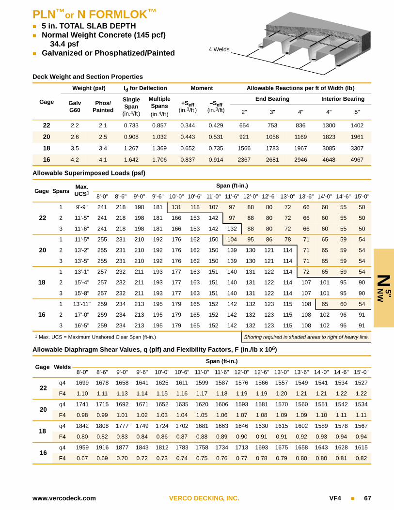
PLN™or N FORMLOK™
5 in. TOTAL SLAB DEPTH Normal Weight Concrete (145 pcf)
34.4 psf Galvanized or Phosphatized/Painted
N 5
"N
W
4 Welds
www.vercodeck.com VERCO DECKING, INC. VF4 67
Deck Weight and Section Properties
Gage
Weight (psf) Id for Deflection Moment Allowable Reactions per ft of Width (lb)
Galv G60
Phos/Painted
Single Span
(in.4/ft)
Multiple Spans
(in.4/ft)
+Seff(in.3/ft )
–Seff(in.3/ft)
End Bearing Interior Bearing
2" 3" 4" 4" 5"
22 2.2 2.1 0.733 0.857 0.344 0.429 654 753 836 1300 1402
20 2.6 2.5 0.908 1.032 0.443 0.531 921 1056 1169 1823 1961
18 3.5 3.4 1.267 1.369 0.652 0.735 1566 1783 1967 3085 3307
16 4.2 4.1 1.642 1.706 0.837 0.914 2367 2681 2946 4648 4967
Allowable Superimposed Loads (psf)
Gage SpansMax.UCS1
Span (ft-in.)
8'-0" 8'-6" 9'-0" 9'-6" 10'-0" 10'-6" 11'-0" 11'-6" 12'-0" 12'-6" 13'-0" 13'-6" 14'-0" 14'-6" 15'-0"
22
1 9'-9" 241 218 198 181 131 118 107 97 88 80 72 66 60 55 50
2 11'-5" 241 218 198 181 166 153 142 97 88 80 72 66 60 55 50
3 11'-6" 241 218 198 181 166 153 142 132 88 80 72 66 60 55 50
20
1 11'-5" 255 231 210 192 176 162 150 104 95 86 78 71 65 59 54
2 13'-2" 255 231 210 192 176 162 150 139 130 121 114 71 65 59 54
3 13'-5" 255 231 210 192 176 162 150 139 130 121 114 71 65 59 54
18
1 13'-1" 257 232 211 193 177 163 151 140 131 122 114 72 65 59 54
2 15'-4" 257 232 211 193 177 163 151 140 131 122 114 107 101 95 90
3 15'-8" 257 232 211 193 177 163 151 140 131 122 114 107 101 95 90
16
1 13'-11" 259 234 213 195 179 165 152 142 132 123 115 108 65 60 54
2 17'-0" 259 234 213 195 179 165 152 142 132 123 115 108 102 96 91
3 16'-5" 259 234 213 195 179 165 152 142 132 123 115 108 102 96 91
1 Max. UCS = Maximum Unshored Clear Span (ft-in.) Shoring required in shaded areas to right of heavy line.
Allowable Diaphragm Shear Values, q (plf) and Flexibility Factors, F (in./lb x 106)
Gage WeldsSpan (ft-in.)
8'-0" 8'-6" 9'-0" 9'-6" 10'-0" 10'-6" 11'-0" 11'-6" 12'-0" 12'-6" 13'-0" 13'-6" 14'-0" 14'-6" 15'-0"
22q4 1699 1678 1658 1641 1625 1611 1599 1587 1576 1566 1557 1549 1541 1534 1527
F4 1.10 1.11 1.13 1.14 1.15 1.16 1.17 1.18 1.19 1.19 1.20 1.21 1.21 1.22 1.22
20q4 1741 1715 1692 1671 1652 1635 1620 1606 1593 1581 1570 1560 1551 1542 1534
F4 0.98 0.99 1.01 1.02 1.03 1.04 1.05 1.06 1.07 1.08 1.09 1.09 1.10 1.11 1.11
18q4 1842 1808 1777 1749 1724 1702 1681 1663 1646 1630 1615 1602 1589 1578 1567
F4 0.80 0.82 0.83 0.84 0.86 0.87 0.88 0.89 0.90 0.91 0.91 0.92 0.93 0.94 0.94
16q4 1959 1916 1877 1843 1812 1783 1758 1734 1713 1693 1675 1658 1643 1628 1615
F4 0.67 0.69 0.70 0.72 0.73 0.74 0.75 0.76 0.77 0.78 0.79 0.80 0.80 0.81 0.82

N 5
½"
NW
PLN™or N FORMLOK™
5½ in. TOTAL SLAB DEPTH Normal Weight Concrete (145 pcf)
40.4 psf Galvanized or Phosphatized/Painted 4 Welds
68 VF4 VERCO DECKING, INC. www.vercodeck.com
Deck Weight and Section Properties
Gage
Weight (psf) Id for Deflection Moment Allowable Reactions per ft of Width (lb)
Galv G60
Phos/Painted
Single Span
(in.4/ft)
Multiple Spans
(in.4/ft)
+Seff(in.3/ft )
–Seff(in.3/ft)
End Bearing Interior Bearing
2" 3" 4" 4" 5"
22 2.2 2.1 0.733 0.857 0.344 0.429 654 753 836 1300 1402
20 2.6 2.5 0.908 1.032 0.443 0.531 921 1056 1169 1823 1961
18 3.5 3.4 1.267 1.369 0.652 0.735 1566 1783 1967 3085 3307
16 4.2 4.1 1.642 1.706 0.837 0.914 2367 2681 2946 4648 4967
Allowable Superimposed Loads (psf)
Gage SpansMax.UCS1
Span (ft-in.)
8'-0" 8'-6" 9'-0" 9'-6" 10'-0" 10'-6" 11'-0" 11'-6" 12'-0" 12'-6" 13'-0" 13'-6" 14'-0" 14'-6" 15'-0"
22
1 9'-4" 264 238 217 158 142 128 115 104 94 85 77 70 64 58 52
2 10'-10" 264 238 217 198 182 168 115 104 94 85 77 70 64 58 52
3 10'-11" 264 238 217 198 182 168 115 104 94 85 77 70 64 58 52
20
1 10'-10" 278 252 229 209 192 177 123 112 101 92 84 76 69 63 57
2 12'-6" 278 252 229 209 192 177 164 152 142 132 84 76 69 63 57
3 12'-9" 278 252 229 209 192 177 164 152 142 132 84 76 69 63 57
18
1 12'-8" 279 252 229 209 192 177 164 152 142 132 83 75 69 62 57
2 14'-8" 279 252 229 209 192 177 164 152 142 132 124 117 110 103 57
3 15'-1" 279 252 229 209 192 177 164 152 142 132 124 117 110 103 98
16
1 13'-5" 279 253 230 210 193 178 164 153 142 133 124 75 68 62 56
2 16'-3" 279 253 230 210 193 178 164 153 142 133 124 117 110 104 98
3 15'-11" 279 253 230 210 193 178 164 153 142 133 124 117 110 104 98
1 Max. UCS = Maximum Unshored Clear Span (ft-in.) Shoring required in shaded areas to right of heavy line.
Allowable Diaphragm Shear Values, q (plf) and Flexibility Factors, F (in./lb x 106)
Gage WeldsSpan (ft-in.)
8'-0" 8'-6" 9'-0" 9'-6" 10'-0" 10'-6" 11'-0" 11'-6" 12'-0" 12'-6" 13'-0" 13'-6" 14'-0" 14'-6" 15'-0"
22q4 1938 1917 1897 1880 1865 1850 1838 1826 1815 1805 1796 1788 1780 1773 1766
F4 0.96 0.97 0.98 0.99 1.00 1.01 1.02 1.02 1.03 1.03 1.04 1.04 1.05 1.05 1.06
20q4 1980 1954 1931 1910 1891 1874 1859 1845 1832 1820 1809 1799 1790 1781 1773
F4 0.86 0.87 0.88 0.89 0.90 0.91 0.92 0.92 0.93 0.94 0.94 0.95 0.95 0.96 0.96
18q4 2081 2047 2016 1988 1963 1941 1920 1902 1885 1869 1854 1841 1828 1817 1806
F4 0.71 0.72 0.73 0.74 0.75 0.76 0.77 0.78 0.78 0.79 0.80 0.80 0.81 0.81 0.82
16q4 2198 2155 2116 2082 2051 2022 1997 1974 1952 1932 1914 1897 1882 1867 1854
F4 0.60 0.61 0.62 0.63 0.64 0.65 0.66 0.67 0.68 0.68 0.69 0.70 0.70 0.71 0.71

PLN™or N FORMLOK™
6 in. TOTAL SLAB DEPTH Normal Weight Concrete (145 pcf)
46.4 psf Galvanized or Phosphatized/Painted
N 6
"N
W
4 Welds
www.vercodeck.com VERCO DECKING, INC. VF4 69
Deck Weight and Section Properties
Gage
Weight (psf) Id for Deflection Moment Allowable Reactions per ft of Width (lb)
Galv G60
Phos/Painted
Single Span
(in.4/ft)
Multiple Spans
(in.4/ft)
+Seff(in.3/ft )
–Seff(in.3/ft)
End Bearing Interior Bearing
2" 3" 4" 4" 5"
22 2.2 2.1 0.733 0.857 0.344 0.429 654 753 836 1300 1402
20 2.6 2.5 0.908 1.032 0.443 0.531 921 1056 1169 1823 1961
18 3.5 3.4 1.267 1.369 0.652 0.735 1566 1783 1967 3085 3307
16 4.2 4.1 1.642 1.706 0.837 0.914 2367 2681 2946 4648 4967
Allowable Superimposed Loads (psf)
Gage SpansMax.UCS1
Span (ft-in.)
8'-0" 8'-6" 9'-0" 9'-6" 10'-0" 10'-6" 11'-0" 11'-6" 12'-0" 12'-6" 13'-0" 13'-6" 14'-0" 14'-6" 15'-0"
22
1 8'-11" 289 261 192 172 154 138 125 113 102 92 83 76 68 62 56
2 10'-4" 289 261 238 217 199 138 125 113 102 92 83 76 68 62 56
3 10'-5" 289 261 238 217 199 138 125 113 102 92 83 76 68 62 56
20
1 10'-4" 304 275 250 229 210 148 133 121 109 99 90 82 74 67 61
2 12'-0" 304 275 250 229 210 193 179 166 155 99 90 82 74 67 61
3 12'-2" 304 275 250 229 210 193 179 166 155 99 90 82 74 67 61
18
1 12'-4" 304 274 250 228 209 193 179 166 154 98 89 81 73 66 60
2 14'-1" 304 274 250 228 209 193 179 166 154 144 135 127 119 66 60
3 14'-7" 304 274 250 228 209 193 179 166 154 144 135 127 119 113 60
16
1 13'-1" 303 274 249 228 209 193 178 166 154 144 135 80 72 66 59
2 15'-7" 303 274 249 228 209 193 178 166 154 144 135 127 119 113 106
3 15'-5" 303 274 249 228 209 193 178 166 154 144 135 127 119 113 106
1 Max. UCS = Maximum Unshored Clear Span (ft-in.) Shoring required in shaded areas to right of heavy line.
Allowable Diaphragm Shear Values, q (plf) and Flexibility Factors, F (in./lb x 106)
Gage WeldsSpan (ft-in.)
8'-0" 8'-6" 9'-0" 9'-6" 10'-0" 10'-6" 11'-0" 11'-6" 12'-0" 12'-6" 13'-0" 13'-6" 14'-0" 14'-6" 15'-0"
22q4 2178 2156 2136 2119 2104 2090 2077 2065 2054 2045 2035 2027 2019 2012 2005
F4 0.86 0.87 0.87 0.88 0.89 0.89 0.90 0.90 0.91 0.91 0.92 0.92 0.93 0.93 0.93
20q4 2219 2193 2170 2149 2130 2113 2098 2084 2071 2059 2048 2038 2029 2020 2012
F4 0.77 0.78 0.79 0.79 0.80 0.81 0.81 0.82 0.82 0.83 0.83 0.84 0.84 0.84 0.85
18q4 2321 2286 2255 2227 2202 2180 2159 2141 2124 2108 2093 2080 2067 2056 2045
F4 0.64 0.65 0.66 0.66 0.67 0.68 0.68 0.69 0.70 0.70 0.71 0.71 0.71 0.72 0.72
16q4 2437 2394 2355 2321 2290 2262 2236 2213 2191 2172 2153 2136 2121 2106 2093
F4 0.54 0.55 0.56 0.57 0.58 0.58 0.59 0.60 0.60 0.61 0.61 0.62 0.62 0.63 0.63

N 6
½"
NW
PLN™or N FORMLOK™
6½ in. TOTAL SLAB DEPTH Normal Weight Concrete (145 pcf)
52.5 psf Galvanized or Phosphatized/Painted 1 Hour Fire Rating
4 Welds
70 VF4 VERCO DECKING, INC. www.vercodeck.com
Deck Weight and Section Properties
Gage
Weight (psf) Id for Deflection Moment Allowable Reactions per ft of Width (lb)
Galv G60
Phos/Painted
Single Span
(in.4/ft)
Multiple Spans
(in.4/ft)
+Seff(in.3/ft )
–Seff(in.3/ft)
End Bearing Interior Bearing
2" 3" 4" 4" 5"
22 2.2 2.1 0.733 0.857 0.344 0.429 654 753 836 1300 1402
20 2.6 2.5 0.908 1.032 0.443 0.531 921 1056 1169 1823 1961
18 3.5 3.4 1.267 1.369 0.652 0.735 1566 1783 1967 3085 3307
16 4.2 4.1 1.642 1.706 0.837 0.914 2367 2681 2946 4648 4967
Allowable Superimposed Loads (psf)
Gage SpansMax.UCS1
Span (ft-in.)
8'-0" 8'-6" 9'-0" 9'-6" 10'-0" 10'-6" 11'-0" 11'-6" 12'-0" 12'-6" 13'-0" 13'-6" 14'-0" 14'-6" 15'-0"
22
1 8'-6" 316 286 209 187 167 150 135 122 110 100 90 82 74 67 60
2 9'-11" 316 286 260 237 167 150 135 122 110 100 90 82 74 67 60
3 10'-0" 316 286 260 237 218 150 135 122 110 100 90 82 74 67 60
20
1 9'-11" 332 301 273 250 178 161 145 131 118 107 97 88 80 73 66
2 11'-6" 332 301 273 250 229 211 196 182 118 107 97 88 80 73 66
3 11'-7" 332 301 273 250 229 211 196 182 118 107 97 88 80 73 66
18
1 12'-0" 331 299 272 248 228 210 195 181 168 106 96 87 79 71 65
2 13'-6" 331 299 272 248 228 210 195 181 168 157 147 138 79 71 65
3 14'-0" 331 299 272 248 228 210 195 181 168 157 147 138 130 71 65
16
1 12'-9" 329 298 271 247 227 209 194 180 168 157 94 85 77 70 63
2 15'-0" 329 298 271 247 227 209 194 180 168 157 147 138 130 122 116
3 15'-1" 329 298 271 247 227 209 194 180 168 157 147 138 130 122 116
1 Max. UCS = Maximum Unshored Clear Span (ft-in.) Shoring required in shaded areas to right of heavy line.
Allowable Diaphragm Shear Values, q (plf) and Flexibility Factors, F (in./lb x 106)
Gage WeldsSpan (ft-in.)
8'-0" 8'-6" 9'-0" 9'-6" 10'-0" 10'-6" 11'-0" 11'-6" 12'-0" 12'-6" 13'-0" 13'-6" 14'-0" 14'-6" 15'-0"
22q4 2417 2395 2376 2358 2343 2329 2316 2304 2293 2284 2275 2266 2258 2251 2244
F4 0.77 0.78 0.79 0.79 0.80 0.80 0.81 0.81 0.81 0.82 0.82 0.82 0.83 0.83 0.83
20q4 2458 2432 2409 2388 2369 2352 2337 2323 2310 2298 2288 2277 2268 2259 2251
F4 0.69 0.70 0.71 0.71 0.72 0.72 0.73 0.73 0.74 0.74 0.75 0.75 0.75 0.75 0.76
18q4 2560 2525 2494 2466 2442 2419 2399 2380 2363 2347 2332 2319 2307 2295 2284
F4 0.58 0.59 0.59 0.60 0.61 0.61 0.62 0.62 0.63 0.63 0.63 0.64 0.64 0.64 0.65
16q4 2677 2633 2594 2560 2529 2501 2475 2452 2430 2411 2392 2376 2360 2345 2332
F4 0.49 0.50 0.51 0.52 0.52 0.53 0.53 0.54 0.54 0.55 0.55 0.56 0.56 0.56 0.57

PLN™or N FORMLOK™
7½ in. TOTAL SLAB DEPTH Normal Weight Concrete (145 pcf)
64.6 psf Galvanized or Phosphatized/Painted 2 Hour Fire Rating
N 7
½"
NW
4 Welds
www.vercodeck.com VERCO DECKING, INC. VF4 71
Deck Weight and Section Properties
Gage
Weight (psf) Id for Deflection Moment Allowable Reactions per ft of Width (lb)
Galv G60
Phos/Painted
Single Span
(in.4/ft)
Multiple Spans
(in.4/ft)
+Seff(in.3/ft )
–Seff(in.3/ft)
End Bearing Interior Bearing
2" 3" 4" 4" 5"
22 2.2 2.1 0.733 0.857 0.344 0.429 654 753 836 1300 1402
20 2.6 2.5 0.908 1.032 0.443 0.531 921 1056 1169 1823 1961
18 3.5 3.4 1.267 1.369 0.652 0.735 1566 1783 1967 3085 3307
16 4.2 4.1 1.642 1.706 0.837 0.914 2367 2681 2946 4648 4967
Allowable Superimposed Loads (psf)
Gage SpansMax.UCS1
Span (ft-in.)
8'-0" 8'-6" 9'-0" 9'-6" 10'-0" 10'-6" 11'-0" 11'-6" 12'-0" 12'-6" 13'-0" 13'-6" 14'-0" 14'-6" 15'-0"
22
1 7'-11" 313 277 246 220 197 177 159 143 129 117 105 95 86 78 70
2 9'-2" 373 338 307 220 197 177 159 143 129 117 105 95 86 78 70
3 9'-3" 373 338 307 220 197 177 159 143 129 117 105 95 86 78 70
20
1 9'-2" 392 355 322 233 209 188 170 153 138 125 113 103 93 84 76
2 10'-8" 392 355 322 295 270 249 170 153 138 125 113 103 93 84 76
3 10'-9" 392 355 322 295 270 249 170 153 138 125 113 103 93 84 76
18
1 11'-5" 389 352 320 292 268 247 229 151 136 123 111 101 91 82 75
2 12'-7" 389 352 320 292 268 247 229 212 198 185 111 101 91 82 75
3 13'-0" 389 352 320 292 268 247 229 212 198 185 173 101 91 82 75
16
1 12'-2" 386 349 317 290 266 246 227 211 197 121 109 99 89 81 73
2 14'-0" 386 349 317 290 266 246 227 211 197 184 172 162 152 81 73
3 14'-4" 386 349 317 290 266 246 227 211 197 184 172 162 152 81 73
1 Max. UCS = Maximum Unshored Clear Span (ft-in.) Shoring required in shaded areas to right of heavy line.
Allowable Diaphragm Shear Values, q (plf) and Flexibility Factors, F (in./lb x 106)
Gage WeldsSpan (ft-in.)
8'-0" 8'-6" 9'-0" 9'-6" 10'-0" 10'-6" 11'-0" 11'-6" 12'-0" 12'-6" 13'-0" 13'-6" 14'-0" 14'-6" 15'-0"
22q4 2895 2873 2854 2836 2821 2807 2794 2782 2772 2762 2753 2744 2736 2729 2722
F4 0.65 0.65 0.65 0.66 0.66 0.67 0.67 0.67 0.67 0.68 0.68 0.68 0.68 0.68 0.69
20q4 2936 2910 2887 2866 2848 2831 2815 2801 2788 2777 2766 2756 2746 2737 2729
F4 0.58 0.59 0.59 0.59 0.60 0.60 0.61 0.61 0.61 0.61 0.62 0.62 0.62 0.62 0.62
18q4 3038 3003 2972 2945 2920 2897 2877 2858 2841 2825 2811 2797 2785 2773 2762
F4 0.49 0.49 0.50 0.50 0.51 0.51 0.51 0.52 0.52 0.52 0.53 0.53 0.53 0.53 0.53
16q4 3155 3111 3073 3038 3007 2979 2953 2930 2908 2889 2871 2854 2838 2824 2810
F4 0.42 0.42 0.43 0.43 0.44 0.44 0.45 0.45 0.45 0.46 0.46 0.46 0.47 0.47 0.47

N 5
"L
WPLN™or N FORMLOK™
5 in. TOTAL SLAB DEPTH Light Weight Concrete (110 pcf)
26.1 psf Galvanized or Phosphatized/Painted
4 Welds
72 VF4 VERCO DECKING, INC. www.vercodeck.com
Deck Weight and Section Properties
Gage
Weight (psf) Id for Deflection Moment Allowable Reactions per ft of Width (lb)
Galv G60
Phos/Painted
Single Span
(in.4/ft)
Multiple Spans
(in.4/ft)
+Seff(in.3/ft )
–Seff(in.3/ft)
End Bearing Interior Bearing
2" 3" 4" 4" 5"
22 2.2 2.1 0.733 0.857 0.344 0.429 654 753 836 1300 1402
20 2.6 2.5 0.908 1.032 0.443 0.531 921 1056 1169 1823 1961
18 3.5 3.4 1.267 1.369 0.652 0.735 1566 1783 1967 3085 3307
16 4.2 4.1 1.642 1.706 0.837 0.914 2367 2681 2946 4648 4967
Allowable Superimposed Loads (psf)
Gage SpansMax.UCS1
Span (ft-in.)
8'-0" 8'-6" 9'-0" 9'-6" 10'-0" 10'-6" 11'-0" 11'-6" 12'-0" 12'-6" 13'-0" 13'-6" 14'-0" 14'-6" 15'-0"
22
1 10'-9" 241 218 198 181 166 153 115 105 96 88 80 74 68 63 58
2 12'-7" 241 218 198 181 166 153 142 132 123 109 80 74 68 63 58
3 12'-8" 241 218 198 181 166 153 142 132 123 109 80 74 68 63 58
20
1 12'-7" 255 231 210 192 176 162 150 139 130 118 86 79 73 67 62
2 14'-3" 255 231 210 192 176 162 150 139 130 118 105 94 84 67 62
3 14'-9" 255 231 210 192 176 162 150 139 130 118 105 94 84 76 62
18
1 13'-11" 257 232 211 193 177 163 151 140 131 122 114 107 73 67 62
2 16'-8" 257 232 211 193 177 163 151 140 131 122 114 107 96 87 78
3 16'-8" 257 232 211 193 177 163 151 140 131 122 114 107 96 87 78
16
1 14'-10" 259 234 213 195 179 165 152 142 132 123 115 108 102 96 62
2 18'-5" 259 234 213 195 179 165 152 142 132 123 115 108 102 96 87
3 17'-6" 259 234 213 195 179 165 152 142 132 123 115 108 102 96 87
1 Max. UCS = Maximum Unshored Clear Span (ft-in.) Shoring required in shaded areas to right of heavy line.
Allowable Diaphragm Shear Values, q (plf) and Flexibility Factors, F (in./lb x 106)
Gage WeldsSpan (ft-in.)
8'-0" 8'-6" 9'-0" 9'-6" 10'-0" 10'-6" 11'-0" 11'-6" 12'-0" 12'-6" 13'-0" 13'-6" 14'-0" 14'-6" 15'-0"
22q4 1375 1353 1334 1317 1301 1287 1274 1262 1252 1242 1233 1224 1217 1209 1203
F4 1.36 1.38 1.40 1.42 1.44 1.45 1.47 1.48 1.49 1.50 1.52 1.53 1.54 1.54 1.55
20q4 1416 1390 1367 1346 1328 1311 1295 1281 1269 1257 1246 1236 1226 1218 1209
F4 1.20 1.23 1.25 1.27 1.28 1.30 1.32 1.33 1.34 1.36 1.37 1.38 1.39 1.40 1.41
18q4 1518 1483 1452 1425 1400 1377 1357 1338 1321 1305 1291 1277 1265 1253 1242
F4 0.97 1.00 1.02 1.04 1.06 1.07 1.09 1.10 1.12 1.13 1.14 1.16 1.17 1.18 1.19
16q4 1635 1591 1553 1518 1487 1459 1433 1410 1389 1369 1351 1334 1318 1304 1290
F4 0.81 0.83 0.85 0.87 0.89 0.91 0.92 0.94 0.95 0.96 0.98 0.99 1.00 1.01 1.02

PLN™or N FORMLOK™
5½ in. TOTAL SLAB DEPTH Light Weight Concrete (110 pcf)
30.7 psf Galvanized or Phosphatized/Painted 1 Hour Fire Rating
N 5
½"
LW
4 Welds
www.vercodeck.com VERCO DECKING, INC. VF4 73
Deck Weight and Section Properties
Gage
Weight (psf) Id for Deflection Moment Allowable Reactions per ft of Width (lb)
Galv G60
Phos/Painted
Single Span
(in.4/ft)
Multiple Spans
(in.4/ft)
+Seff(in.3/ft )
–Seff(in.3/ft)
End Bearing Interior Bearing
2" 3" 4" 4" 5"
22 2.2 2.1 0.733 0.857 0.344 0.429 654 753 836 1300 1402
20 2.6 2.5 0.908 1.032 0.443 0.531 921 1056 1169 1823 1961
18 3.5 3.4 1.267 1.369 0.652 0.735 1566 1783 1967 3085 3307
16 4.2 4.1 1.642 1.706 0.837 0.914 2367 2681 2946 4648 4967
Allowable Superimposed Loads (psf)
Gage SpansMax.UCS1
Span (ft-in.)
8'-0" 8'-6" 9'-0" 9'-6" 10'-0" 10'-6" 11'-0" 11'-6" 12'-0" 12'-6" 13'-0" 13'-6" 14'-0" 14'-6" 15'-0"
22
1 10'-3" 264 238 217 198 182 137 124 113 103 95 87 79 73 67 62
2 11'-11" 264 238 217 198 182 168 155 144 103 95 87 79 73 67 62
3 12'-1" 264 238 217 198 182 168 155 144 134 95 87 79 73 67 62
20
1 12'-0" 278 252 229 209 192 177 164 152 142 101 93 85 78 72 66
2 13'-8" 278 252 229 209 192 177 164 152 142 132 124 116 78 72 66
3 14'-1" 278 252 229 209 192 177 164 152 142 132 124 116 110 72 66
18
1 13'-6" 279 252 229 209 192 177 164 152 142 132 124 117 78 72 66
2 16'-0" 279 252 229 209 192 177 164 152 142 132 124 117 110 103 98
3 16'-1" 279 252 229 209 192 177 164 152 142 132 124 117 110 103 98
16
1 14'-4" 279 253 230 210 193 178 164 153 142 133 124 117 110 71 65
2 17'-9" 279 253 230 210 193 178 164 153 142 133 124 117 110 104 98
3 16'-11" 279 253 230 210 193 178 164 153 142 133 124 117 110 104 98
1 Max. UCS = Maximum Unshored Clear Span (ft-in.) Shoring required in shaded areas to right of heavy line.
Allowable Diaphragm Shear Values, q (plf) and Flexibility Factors, F (in./lb x 106)
Gage WeldsSpan (ft-in.)
8'-0" 8'-6" 9'-0" 9'-6" 10'-0" 10'-6" 11'-0" 11'-6" 12'-0" 12'-6" 13'-0" 13'-6" 14'-0" 14'-6" 15'-0"
22q4 1533 1511 1492 1475 1459 1445 1432 1420 1410 1400 1391 1382 1375 1367 1361
F4 1.22 1.24 1.25 1.27 1.28 1.29 1.30 1.32 1.33 1.33 1.34 1.35 1.36 1.37 1.37
20q4 1574 1548 1525 1504 1486 1469 1453 1439 1427 1415 1404 1394 1384 1376 1367
F4 1.08 1.10 1.12 1.13 1.15 1.16 1.17 1.18 1.20 1.21 1.21 1.22 1.23 1.24 1.25
18q4 1676 1641 1610 1583 1558 1535 1515 1496 1479 1463 1449 1435 1423 1411 1400
F4 0.88 0.90 0.92 0.93 0.95 0.96 0.98 0.99 1.00 1.01 1.02 1.03 1.04 1.05 1.06
16q4 1793 1749 1711 1676 1645 1617 1591 1568 1547 1527 1509 1492 1476 1462 1448
F4 0.74 0.76 0.77 0.79 0.80 0.82 0.83 0.84 0.85 0.87 0.88 0.89 0.89 0.90 0.91
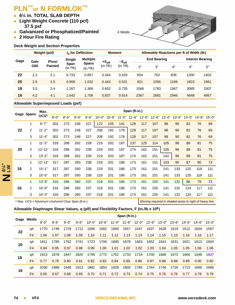
N 6
¼"
LW
PLN™or N FORMLOK™
6¼ in. TOTAL SLAB DEPTH Light Weight Concrete (110 pcf)
37.5 psf Galvanized or Phosphatized/Painted 2 Hour Fire Rating
4 Welds
74 VF4 VERCO DECKING, INC. www.vercodeck.com
Deck Weight and Section Properties
Gage
Weight (psf) Id for Deflection Moment Allowable Reactions per ft of Width (lb)
Galv G60
Phos/Painted
Single Span
(in.4/ft)
Multiple Spans
(in.4/ft)
+Seff(in.3/ft )
–Seff(in.3/ft)
End Bearing Interior Bearing
2" 3" 4" 4" 5"
22 2.2 2.1 0.733 0.857 0.344 0.429 654 753 836 1300 1402
20 2.6 2.5 0.908 1.032 0.443 0.531 921 1056 1169 1823 1961
18 3.5 3.4 1.267 1.369 0.652 0.735 1566 1783 1967 3085 3307
16 4.2 4.1 1.642 1.706 0.837 0.914 2367 2681 2946 4648 4967
Allowable Superimposed Loads (psf)
Gage SpansMax.UCS1
Span (ft-in.)
8'-0" 8'-6" 9'-0" 9'-6" 10'-0" 10'-6" 11'-0" 11'-6" 12'-0" 12'-6" 13'-0" 13'-6" 14'-0" 14'-6" 15'-0"
22
1 9'-7" 302 273 248 227 172 155 141 128 117 107 98 90 82 76 69
2 11'-2" 302 273 248 227 208 192 178 128 117 107 98 90 82 76 69
3 11'-4" 302 273 248 227 208 192 178 128 117 107 98 90 82 76 69
20
1 11'-3" 318 288 262 239 219 202 187 137 125 114 105 96 88 81 75
2 12'-11" 318 288 262 239 219 202 187 174 162 151 105 96 88 81 75
3 13'-2" 318 288 262 239 219 202 187 174 162 151 142 96 88 81 75
18
1 12'-11" 317 287 260 238 219 201 186 173 161 151 103 95 87 80 73
2 15'-1" 317 287 260 238 219 201 186 173 161 151 141 133 125 118 111
3 15'-5" 317 287 260 238 219 201 186 173 161 151 141 133 125 118 111
16
1 13'-9" 316 286 260 237 218 201 186 173 161 150 141 132 86 79 72
2 16'-9" 316 286 260 237 218 201 186 173 161 150 141 132 124 117 111
3 16'-3" 316 286 260 237 218 201 186 173 161 150 141 132 124 117 111
1 Max. UCS = Maximum Unshored Clear Span (ft-in.) Shoring required in shaded areas to right of heavy line.
Allowable Diaphragm Shear Values, q (plf) and Flexibility Factors, F (in./lb x 106)
Gage WeldsSpan (ft-in.)
8'-0" 8'-6" 9'-0" 9'-6" 10'-0" 10'-6" 11'-0" 11'-6" 12'-0" 12'-6" 13'-0" 13'-6" 14'-0" 14'-6" 15'-0"
22q4 1770 1748 1729 1712 1696 1682 1669 1657 1647 1637 1628 1619 1612 1604 1597
F4 1.06 1.07 1.08 1.09 1.10 1.11 1.12 1.13 1.13 1.14 1.15 1.15 1.16 1.16 1.17
20q4 1811 1785 1762 1741 1723 1706 1690 1676 1663 1652 1641 1631 1621 1613 1604
F4 0.94 0.95 0.97 0.98 0.99 1.00 1.01 1.02 1.02 1.03 1.04 1.05 1.05 1.06 1.06
18q4 1913 1878 1847 1820 1795 1772 1752 1733 1716 1700 1686 1672 1660 1648 1637
F4 0.77 0.79 0.80 0.81 0.82 0.83 0.84 0.85 0.86 0.87 0.88 0.88 0.89 0.90 0.90
16q4 2030 1986 1948 1913 1882 1854 1828 1805 1784 1764 1746 1729 1713 1699 1685
F4 0.65 0.67 0.68 0.69 0.70 0.71 0.72 0.73 0.74 0.75 0.76 0.76 0.77 0.78 0.78
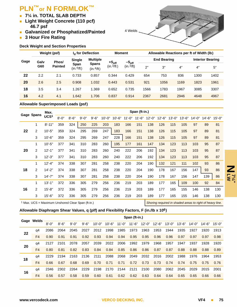
PLN™or N FORMLOK™
7¼ in. TOTAL SLAB DEPTH Light Weight Concrete (110 pcf)
46.7 psf Galvanized or Phosphatized/Painted 3 Hour Fire Rating
N 7
¼"
LW
4 Welds
www.vercodeck.com VERCO DECKING, INC. VF4 75
Deck Weight and Section Properties
Gage
Weight (psf) Id for Deflection Moment Allowable Reactions per ft of Width (lb)
Galv G60
Phos/Painted
Single Span
(in.4/ft)
Multiple Spans
(in.4/ft)
+Seff(in.3/ft )
–Seff(in.3/ft)
End Bearing Interior Bearing
2" 3" 4" 4" 5"
22 2.2 2.1 0.733 0.857 0.344 0.429 654 753 836 1300 1402
20 2.6 2.5 0.908 1.032 0.443 0.531 921 1056 1169 1823 1961
18 3.5 3.4 1.267 1.369 0.652 0.735 1566 1783 1967 3085 3307
16 4.2 4.1 1.642 1.706 0.837 0.914 2367 2681 2946 4648 4967
Allowable Superimposed Loads (psf)
Gage SpansMax.UCS1
Span (ft-in.)
8'-0" 8'-6" 9'-0" 9'-6" 10'-0" 10'-6" 11'-0" 11'-6" 12'-0" 12'-6" 13'-0" 13'-6" 14'-0" 14'-6" 15'-0"
22
1 8'-11" 359 324 250 225 203 183 166 151 138 126 115 105 97 89 81
2 10'-5" 359 324 295 269 247 183 166 151 138 126 115 105 97 89 81
3 10'-6" 359 324 295 269 247 228 166 151 138 126 115 105 97 89 81
20
1 10'-5" 377 341 310 283 260 195 177 161 147 134 123 113 103 95 87
2 12'-1" 377 341 310 283 260 240 222 206 192 134 123 113 103 95 87
3 12'-3" 377 341 310 283 260 240 222 206 192 134 123 113 103 95 87
18
1 12'-4" 374 338 307 281 258 238 220 204 190 132 121 111 102 93 86
2 14'-2" 374 338 307 281 258 238 220 204 190 178 167 156 147 93 86
3 14'-7" 374 338 307 281 258 238 220 204 190 178 167 156 147 139 86
16
1 13'-1" 372 336 305 279 256 236 219 203 189 177 165 109 100 92 84
2 15'-8" 372 336 305 279 256 236 219 203 189 177 165 155 146 138 130
3 15'-6" 372 336 305 279 256 236 219 203 189 177 165 155 146 138 130
1 Max. UCS = Maximum Unshored Clear Span (ft-in.) Shoring required in shaded areas to right of heavy line.
Allowable Diaphragm Shear Values, q (plf) and Flexibility Factors, F (in./lb x 106)
Gage WeldsSpan (ft-in.)
8'-0" 8'-6" 9'-0" 9'-6" 10'-0" 10'-6" 11'-0" 11'-6" 12'-0" 12'-6" 13'-0" 13'-6" 14'-0" 14'-6" 15'-0"
22q4 2086 2064 2045 2027 2012 1998 1985 1973 1963 1953 1944 1935 1927 1920 1913
F4 0.90 0.91 0.91 0.92 0.93 0.94 0.94 0.95 0.95 0.96 0.96 0.97 0.97 0.97 0.98
20q4 2127 2101 2078 2057 2039 2022 2006 1992 1979 1968 1957 1947 1937 1928 1920
F4 0.80 0.81 0.82 0.83 0.84 0.84 0.85 0.86 0.86 0.87 0.87 0.88 0.88 0.88 0.89
18q4 2229 2194 2163 2136 2111 2088 2068 2049 2032 2016 2002 1988 1976 1964 1953
F4 0.66 0.67 0.68 0.69 0.70 0.71 0.71 0.72 0.73 0.73 0.74 0.74 0.75 0.75 0.76
16q4 2346 2302 2264 2229 2198 2170 2144 2121 2100 2080 2062 2045 2029 2015 2001
F4 0.56 0.57 0.58 0.59 0.60 0.61 0.62 0.62 0.63 0.64 0.64 0.65 0.65 0.66 0.66
76 VF4 VERCO DECKING, INC. www.vercodeck.com
W2/
W3
N
OF
ILL
FORMLOK™ DECK WITHOUT FILL - TECHNICAL DATA
This section presents vertical load and diaphragm design information for PLW2™, W2, PLW3™, and W3 FORMLOK™ decks used without structural concrete fill. PLW2™ and PLW3™ FORMLOK™ decks uti-lize the revolutionary PunchLok® system for sidelap connections.
Uniform Load Tables The tables on pages 78–81 list the allowable uniform loads. These are the total uniform loads which can be applied to the FORMLOK deck. Values are based on the allowable bending moment (stress) and limit-ing deflection to either L/360 or L/180. The symbol ♦♦♦ indicates that the allowable uniform load based on deflection exceeds the allowable load based on flexure (stress). See page 86 for the formulas used to determine the allowable uniform loads. Note that self-weight of the deck should be included when determining dead load.
Bearing Verco recommends 2 in. minimum bearing on perpendicular supports for FORMLOK deck. The required bearing should be verified based on specific project conditions. Adequate bearing is required to prevent web crippling of the deck and to allow for proper attachment of the deck. The allowable reactions are shown in the section properties tables.
Web crippling due to concentrated loads located directly over supports should also be evaluated. Contact the Verco Engineering department for additional information.
Adequate bearing at parallel supports should be provided to make the specified connections.
Concentrated Loads Concentrated loads should be evaluated based on the deck section prop-erties and material strength.
FORMLOK DECK DIAPHRAGMSThe diaphragm shear values for FORMLOK deck used without concrete fill are based on attaching the deck to the supports with puddle welds. The attachment patterns for each profile are shown in the illustrations included with the tables.
Diaphragm Load Tables Designers should observe the following notes when working with these tables:
• The allowable stress increase permitted for load combinations in IBC Section 1605.3.2, including wind or seismic forces, shall not be used for allowable diaphragm shears.
• The flexibility factor (F) is the number of microinches a diaphragm web will deflect in a span of 1 ft under a shear load of 1 pound per ft.
• R is the vertical load span (spacing between supports), Lv, of the deck units divided by the length, Ls, of the deck sheet: R = Lv / Ls.
• The flexibility limitations in Verco’s evaluation report may be used as a guide in lieu of a rational analysis of the anticipated deflections.
• VSC = Verco Sidelap Connection made with the Verco PunchLok® tool on PLW2 and PLW3 FORMLOK decks.
• BP = Button punched sidelap connection. Screws may be substituted for BP at same spacing. See page 12 for additional information.
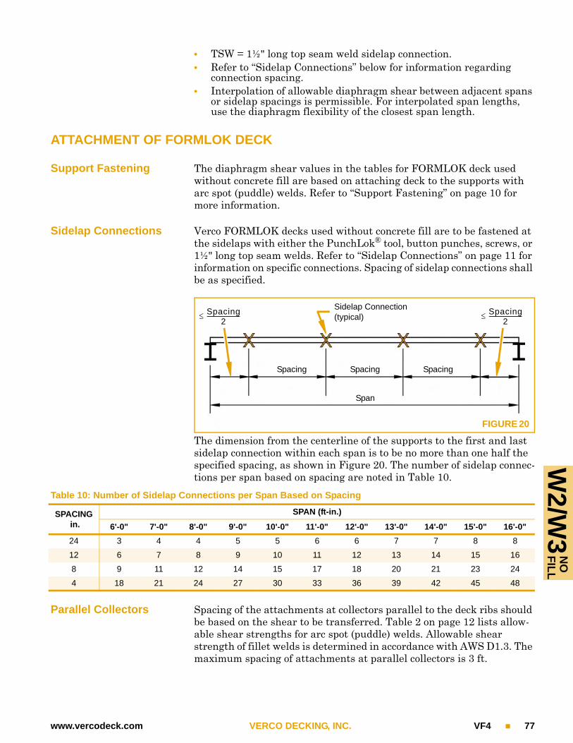
www.vercodeck.com VERCO DECKING, INC. VF4 77
W2/W
3 F
ILL
NO
• TSW = 1½" long top seam weld sidelap connection.• Refer to “Sidelap Connections” below for information regarding
connection spacing.• Interpolation of allowable diaphragm shear between adjacent spans
or sidelap spacings is permissible. For interpolated span lengths, use the diaphragm flexibility of the closest span length.
ATTACHMENT OF FORMLOK DECK
Support Fastening The diaphragm shear values in the tables for FORMLOK deck used without concrete fill are based on attaching deck to the supports with arc spot (puddle) welds. Refer to “Support Fastening” on page 10 for more information.
Sidelap Connections Verco FORMLOK decks used without concrete fill are to be fastened at the sidelaps with either the PunchLok® tool, button punches, screws, or 1½" long top seam welds. Refer to “Sidelap Connections” on page 11 for information on specific connections. Spacing of sidelap connections shall be as specified.
The dimension from the centerline of the supports to the first and last sidelap connection within each span is to be no more than one half the specified spacing, as shown in Figure 20. The number of sidelap connec-tions per span based on spacing are noted in Table 10.
Parallel Collectors Spacing of the attachments at collectors parallel to the deck ribs should be based on the shear to be transferred. Table 2 on page 12 lists allow-able shear strengths for arc spot (puddle) welds. Allowable shear strength of fillet welds is determined in accordance with AWS D1.3. The maximum spacing of attachments at parallel collectors is 3 ft.
Sidelap Connection(typical)
Spacing2
------------------------------
FIGURE 20
Spacing Spacing Spacing
Span
Spacing
2------------------------------
Table 10: Number of Sidelap Connections per Span Based on Spacing
SPACING in.
SPAN (ft-in.)
6'-0" 7'-0" 8'-0" 9'-0" 10'-0" 11'-0" 12'-0" 13'-0" 14'-0" 15'-0" 16'-0"
24 3 4 4 5 5 6 6 7 7 8 8
12 6 7 8 9 10 11 12 13 14 15 16
8 9 11 12 14 15 17 18 20 21 23 24
4 18 21 24 27 30 33 36 39 42 45 48

PLW2™or W2 FORMLOK™
2" Deep Deck Without Concrete Fill Galvanized or Phosphatized/Painted
W2
NO
FIL
L
78 VF4 VERCO DECKING, INC. www.vercodeck.com
Allowable Uniform Loads (psf)
GAGESPAN (ft-in.)
6'-0" 6'-6" 7'-0" 7'-6" 8'-0" 8'-6" 9'-0" 9'-6" 10'-0" 10'-6" 11'-0" 11'-6" 12'-0" 12'-6" 13'-0" 13'-6" 14'-0"
SINGLE SPAN
22
Stress 137 116 100 87 77 68 61 55 49 45 41 37 34 31 29 27 25
L/360 69 54 43 35 29 24 20 17 15 13 11 10 9 8 7 6 5
L/180 ♦♦♦ 108 87 71 58 48 41 35 30 26 22 20 17 15 14 12 11
21
Stress 157 134 116 101 88 78 70 63 57 51 47 43 39 36 33 31 29
L/360 77 61 49 40 33 27 23 19 17 14 13 11 10 9 8 7 6
L/180 154 121 97 79 65 54 46 39 33 29 25 22 19 17 15 14 12
20
Stress 179 153 132 115 101 89 80 72 65 59 53 49 45 41 38 35 33
L/360 86 67 54 44 36 30 25 22 18 16 14 12 11 9 8 8 7
L/180 171 135 108 88 72 60 51 43 37 32 28 24 21 19 17 15 13
19
Stress 225 192 165 144 127 112 100 90 81 73 67 61 56 52 48 44 41
L/360 102 80 64 52 43 36 30 26 22 19 17 14 13 11 10 9 8
L/180 204 160 128 104 86 72 60 51 44 38 33 29 25 23 20 18 16
18
Stress 262 223 192 167 147 130 116 104 94 85 78 71 65 60 56 52 48
L/360 114 90 72 59 48 40 34 29 25 21 19 16 14 13 11 10 9
L/180 229 180 144 117 96 80 68 58 49 43 37 32 29 25 22 20 18
16
Stress 300 295 254 222 195 172 154 138 125 113 103 94 87 80 74 68 64
L/360 143 113 90 73 60 50 42 36 31 27 23 20 18 16 14 13 11
L/180 287 225 180 147 121 101 85 72 62 53 47 41 36 32 28 25 23
DOUBLE SPAN
22
Stress 142 121 104 91 80 71 63 57 51 46 42 39 36 33 30 28 26
L/360 ♦♦♦ ♦♦♦ 104 85 70 58 49 42 36 31 27 24 21 18 16 15 13
L/180 ♦♦♦ ♦♦♦ ♦♦♦ ♦♦♦ ♦♦♦ ♦♦♦ ♦♦♦ ♦♦♦ ♦♦♦ ♦♦♦ ♦♦♦ ♦♦♦ ♦♦♦ ♦♦♦ ♦♦♦ ♦♦♦ 26
21
Stress 163 139 120 105 92 81 73 65 59 53 49 44 41 38 35 32 30
L/360 ♦♦♦ ♦♦♦ 117 95 78 65 55 47 40 35 30 26 23 21 18 16 15
L/180 ♦♦♦ ♦♦♦ ♦♦♦ ♦♦♦ ♦♦♦ ♦♦♦ ♦♦♦ ♦♦♦ ♦♦♦ ♦♦♦ ♦♦♦ ♦♦♦ ♦♦♦ ♦♦♦ ♦♦♦ ♦♦♦ 29
20
Stress 185 158 136 118 104 92 82 74 67 60 55 50 46 43 39 37 34
L/360 ♦♦♦ ♦♦♦ 130 105 87 72 61 52 44 38 33 29 26 23 20 18 16
L/180 ♦♦♦ ♦♦♦ ♦♦♦ ♦♦♦ ♦♦♦ ♦♦♦ ♦♦♦ ♦♦♦ ♦♦♦ ♦♦♦ ♦♦♦ ♦♦♦ ♦♦♦ ♦♦♦ ♦♦♦ 36 32
(Continued on following page)

W
2 F
ILL
NO
PLW2™or W2 FORMLOK™
2" Deep Deck Without Concrete Fill Galvanized or Phosphatized/Painted
www.vercodeck.com VERCO DECKING, INC. VF4 79
DOUBLE SPAN (continued)
19
Stress 231 196 169 148 130 115 102 92 83 75 69 63 58 53 49 46 42
L/360 ♦♦♦ 193 155 126 104 86 73 62 53 46 40 35 31 27 24 22 19
L/180 ♦♦♦ ♦♦♦ ♦♦♦ ♦♦♦ ♦♦♦ ♦♦♦ ♦♦♦ ♦♦♦ ♦♦♦ ♦♦♦ ♦♦♦ ♦♦♦ ♦♦♦ ♦♦♦ 48 43 39
18
Stress 267 228 196 171 150 133 119 107 96 87 80 73 67 62 57 53 49
L/360 ♦♦♦ 216 173 141 116 97 82 69 59 51 45 39 34 30 27 24 22
L/180 ♦♦♦ ♦♦♦ ♦♦♦ ♦♦♦ ♦♦♦ ♦♦♦ ♦♦♦ ♦♦♦ ♦♦♦ ♦♦♦ ♦♦♦ ♦♦♦ ♦♦♦ 61 54 48 43
16
Stress 300 300 260 227 199 177 158 141 128 116 105 96 89 82 76 70 65
L/360 ♦♦♦ 271 217 177 146 121 102 87 75 64 56 49 43 38 34 30 27
L/180 ♦♦♦ ♦♦♦ ♦♦♦ ♦♦♦ ♦♦♦ ♦♦♦ ♦♦♦ ♦♦♦ ♦♦♦ ♦♦♦ ♦♦♦ ♦♦♦ 86 76 68 61 54
TRIPLE SPAN
22
Stress 178 151 131 114 100 89 79 71 64 58 53 48 44 41 38 35 33
L/360 130 102 82 66 55 46 38 33 28 24 21 18 16 14 13 11 10
L/180 ♦♦♦ ♦♦♦ ♦♦♦ ♦♦♦ ♦♦♦ ♦♦♦ 77 65 56 48 42 37 32 29 26 23 20
21
Stress 204 174 150 131 115 102 91 81 74 67 61 56 51 47 43 40 38
L/360 145 114 92 74 61 51 43 37 31 27 24 21 18 16 14 13 11
L/180 ♦♦♦ ♦♦♦ ♦♦♦ ♦♦♦ ♦♦♦ ♦♦♦ 86 73 63 54 47 41 36 32 29 26 23
20
Stress 231 197 170 148 130 115 103 92 83 76 69 63 58 53 49 46 42
L/360 161 127 101 82 68 57 48 41 35 30 26 23 20 18 16 14 13
L/180 ♦♦♦ ♦♦♦ ♦♦♦ ♦♦♦ ♦♦♦ 113 95 81 70 60 52 46 40 36 32 28 25
19
Stress 288 246 212 184 162 144 128 115 104 94 86 78 72 66 61 57 53
L/360 192 151 121 98 81 68 57 48 41 36 31 27 24 21 19 17 15
L/180 ♦♦♦ ♦♦♦ ♦♦♦ ♦♦♦ 162 135 114 97 83 72 62 55 48 42 38 34 30
18
Stress 300 285 245 214 188 166 148 133 120 109 99 91 84 77 71 66 61
L/360 215 169 136 110 91 76 64 54 47 40 35 31 27 24 21 19 17
L/180 ♦♦♦ ♦♦♦ ♦♦♦ ♦♦♦ 182 151 128 109 93 80 70 61 54 48 42 38 34
16
Stress 300 300 300 284 249 221 197 177 160 145 132 121 111 102 94 88 81
L/360 270 212 170 138 114 95 80 68 58 50 44 38 34 30 27 24 21
L/180 ♦♦♦ ♦♦♦ ♦♦♦ 276 228 190 160 136 117 101 88 77 67 60 53 47 42
Notes:1. Stress = Uniform load which produces maximum allowable stress in deck.2. L/360 = Uniform load which produces L/360 deflection in deck. L/180 = Uniform load which produces L/180 deflection in deck.3. Self-weight of the deck should be included when determining dead load.4. The symbol ♦♦♦ indicates allowable uniform load based on deflection exceeds allowable uniform load based on stress.
Allowable Uniform Loads (psf) (continued)
GAGESPAN (ft-in.)
6'-0" 6'-6" 7'-0" 7'-6" 8'-0" 8'-6" 9'-0" 9'-6" 10'-0" 10'-6" 11'-0" 11'-6" 12'-0" 12'-6" 13'-0" 13'-6" 14'-0"

W3
NO
FIL
LPLW3™or W3 FORMLOK™
3" Deep Deck Without Concrete Fill Galvanized or Phosphatized/Painted
80 VF4 VERCO DECKING, INC. www.vercodeck.com
Allowable Uniform Loads (psf)
GAGESPAN (ft-in.)
6'-0" 6'-6" 7'-0" 7'-6" 8'-0" 8'-6" 9'-0" 9'-6" 10'-0" 10'-6" 11'-0" 12'-0" 13'-0" 14'-0" 15'-0" 16'-0"
SINGLE SPAN
22
Stress 218 186 160 140 123 109 97 87 79 71 65 55 47 40 35 31
L/360 149 117 94 76 63 52 44 38 32 28 24 19 15 12 10 8
L/180 ♦♦♦ ♦♦♦ ♦♦♦ ♦♦♦ ♦♦♦ 105 88 75 64 56 48 37 29 23 19 16
21
Stress 252 214 185 161 142 125 112 100 91 82 75 63 54 46 40 35
L/360 167 131 105 85 70 59 49 42 36 31 27 21 16 13 11 9
L/180 ♦♦♦ ♦♦♦ ♦♦♦ ♦♦♦ 141 117 99 84 72 62 54 42 33 26 21 18
20
Stress 283 241 208 181 159 141 126 113 102 93 84 71 60 52 45 40
L/360 184 145 116 94 78 65 54 46 40 34 30 23 18 14 12 10
L/180 ♦♦♦ ♦♦♦ ♦♦♦ ♦♦♦ 155 129 109 93 79 69 60 46 36 29 24 19
19
Stress 300 300 260 226 199 176 157 141 127 115 105 88 75 65 57 50
L/360 216 170 136 111 91 76 64 54 47 40 35 27 21 17 14 11
L/180 ♦♦♦ ♦♦♦ ♦♦♦ 221 182 152 128 109 93 81 70 54 43 34 28 23
18
Stress 300 300 300 267 235 208 186 167 150 136 124 104 89 77 67 59
L/360 246 193 155 126 104 86 73 62 53 46 40 31 24 19 16 13
L/180 ♦♦♦ ♦♦♦ ♦♦♦ 252 207 173 146 124 106 92 80 61 48 39 31 26
16
Stress 300 300 300 300 300 268 239 215 194 176 160 134 115 99 86 76
L/360 ♦♦♦ 242 193 157 130 108 91 77 66 57 50 38 30 24 20 16
L/180 ♦♦♦ ♦♦♦ ♦♦♦ ♦♦♦ 259 216 182 155 133 115 100 77 60 48 39 32
DOUBLE SPAN
22
Stress 228 194 167 146 128 113 101 91 82 74 68 57 49 42 36 32
L/360 ♦♦♦ ♦♦♦ ♦♦♦ ♦♦♦ ♦♦♦ ♦♦♦ ♦♦♦ 90 78 67 58 45 35 28 23 19
L/180 ♦♦♦ ♦♦♦ ♦♦♦ ♦♦♦ ♦♦♦ ♦♦♦ ♦♦♦ ♦♦♦ ♦♦♦ ♦♦♦ ♦♦♦ ♦♦♦ ♦♦♦ ♦♦♦ ♦♦♦ ♦♦♦
21
Stress 261 222 192 167 147 130 116 104 94 85 78 65 56 48 42 37
L/360 ♦♦♦ ♦♦♦ ♦♦♦ ♦♦♦ ♦♦♦ ♦♦♦ ♦♦♦ 101 87 75 65 50 40 32 26 21
L/180 ♦♦♦ ♦♦♦ ♦♦♦ ♦♦♦ ♦♦♦ ♦♦♦ ♦♦♦ ♦♦♦ ♦♦♦ ♦♦♦ ♦♦♦ ♦♦♦ ♦♦♦ ♦♦♦ ♦♦♦ ♦♦♦
20
Stress 293 250 216 188 165 146 130 117 106 96 87 73 62 54 47 41
L/360 ♦♦♦ ♦♦♦ ♦♦♦ ♦♦♦ ♦♦♦ ♦♦♦ ♦♦♦ 111 96 83 72 55 44 35 28 23
L/180 ♦♦♦ ♦♦♦ ♦♦♦ ♦♦♦ ♦♦♦ ♦♦♦ ♦♦♦ ♦♦♦ ♦♦♦ ♦♦♦ ♦♦♦ ♦♦♦ ♦♦♦ ♦♦♦ ♦♦♦ ♦♦♦
(Continued on following page)

W
3 F
ILL
NO
PLW3™or W3 FORMLOK™
3" Deep Deck Without Concrete Fill Galvanized or Phosphatized/Painted
www.vercodeck.com VERCO DECKING, INC. VF4 81
DOUBLE SPAN (continued)
19
Stress 300 300 266 232 204 180 161 144 130 118 108 91 77 67 58 51
L/360 ♦♦♦ ♦♦♦ ♦♦♦ ♦♦♦ ♦♦♦ ♦♦♦ 154 131 112 97 84 65 51 41 33 27
L/180 ♦♦♦ ♦♦♦ ♦♦♦ ♦♦♦ ♦♦♦ ♦♦♦ ♦♦♦ ♦♦♦ ♦♦♦ ♦♦♦ ♦♦♦ ♦♦♦ ♦♦♦ ♦♦♦ ♦♦♦ ♦♦♦
18
Stress 300 300 300 273 240 213 190 170 154 139 127 107 91 78 68 60
L/360 ♦♦♦ ♦♦♦ ♦♦♦ ♦♦♦ ♦♦♦ 208 175 149 128 110 96 74 58 47 38 31
L/180 ♦♦♦ ♦♦♦ ♦♦♦ ♦♦♦ ♦♦♦ ♦♦♦ ♦♦♦ ♦♦♦ ♦♦♦ ♦♦♦ ♦♦♦ ♦♦♦ ♦♦♦ ♦♦♦ ♦♦♦ ♦♦♦
16
Stress 300 300 300 300 300 267 239 214 193 175 160 134 114 99 86 75
L/360 ♦♦♦ ♦♦♦ ♦♦♦ ♦♦♦ ♦♦♦ 260 219 186 160 138 120 92 73 58 47 39
L/180 ♦♦♦ ♦♦♦ ♦♦♦ ♦♦♦ ♦♦♦ ♦♦♦ ♦♦♦ ♦♦♦ ♦♦♦ ♦♦♦ ♦♦♦ ♦♦♦ ♦♦♦ ♦♦♦ ♦♦♦ ♦♦♦
TRIPLE SPAN
22
Stress 285 243 209 182 160 142 127 114 103 93 85 71 61 52 46 40
L/360 281 221 177 144 119 99 83 71 61 52 46 35 28 22 18 15
L/180 ♦♦♦ ♦♦♦ ♦♦♦ ♦♦♦ ♦♦♦ ♦♦♦ ♦♦♦ ♦♦♦ ♦♦♦ ♦♦♦ ♦♦♦ 70 55 44 36 30
21
Stress 300 278 240 209 184 163 145 130 118 107 97 82 70 60 52 46
L/360 ♦♦♦ 247 198 161 133 111 93 79 68 59 51 39 31 25 20 17
L/180 ♦♦♦ ♦♦♦ ♦♦♦ ♦♦♦ ♦♦♦ ♦♦♦ ♦♦♦ ♦♦♦ ♦♦♦ ♦♦♦ ♦♦♦ 79 62 50 40 33
20
Stress 300 300 269 235 206 183 163 146 132 120 109 92 78 67 59 52
L/360 ♦♦♦ 272 218 177 146 122 103 87 75 65 56 43 34 27 22 18
L/180 ♦♦♦ ♦♦♦ ♦♦♦ ♦♦♦ ♦♦♦ ♦♦♦ ♦♦♦ ♦♦♦ ♦♦♦ ♦♦♦ ♦♦♦ 87 68 55 44 37
19
Stress 300 300 300 290 255 226 201 181 163 148 135 113 96 83 72 64
L/360 ♦♦♦ ♦♦♦ 257 209 172 143 121 103 88 76 66 51 40 32 26 21
L/180 ♦♦♦ ♦♦♦ ♦♦♦ ♦♦♦ ♦♦♦ ♦♦♦ ♦♦♦ ♦♦♦ ♦♦♦ ♦♦♦ 132 102 80 64 52 43
18
Stress 300 300 300 300 300 266 237 213 192 174 159 133 114 98 85 75
L/360 ♦♦♦ ♦♦♦ 292 237 195 163 137 117 100 86 75 58 46 36 30 24
L/180 ♦♦♦ ♦♦♦ ♦♦♦ ♦♦♦ ♦♦♦ ♦♦♦ ♦♦♦ ♦♦♦ ♦♦♦ 173 150 116 91 73 59 49
16
Stress 300 300 300 300 300 300 298 268 242 219 200 168 143 123 107 94
L/360 ♦♦♦ ♦♦♦ ♦♦♦ 296 244 204 172 146 125 108 94 72 57 46 37 31
L/180 ♦♦♦ ♦♦♦ ♦♦♦ ♦♦♦ ♦♦♦ ♦♦♦ ♦♦♦ ♦♦♦ ♦♦♦ 216 188 145 114 91 74 61
Notes:1. Stress = Uniform load which produces maximum allowable stress in deck.2. L/360 = Uniform load which produces L/360 deflection in deck. L/180 = Uniform load which produces L/180 deflection in deck.3. Self-weight of the deck should be included when determining dead load.4. The symbol ♦♦♦ indicates allowable uniform load based on deflection exceeds allowable uniform load based on stress.
Allowable Uniform Loads (psf) (continued)
GAGESPAN (ft-in.)
6'-0" 6'-6" 7'-0" 7'-6" 8'-0" 8'-6" 9'-0" 9'-6" 10'-0" 10'-6" 11'-0" 12'-0" 13'-0" 14'-0" 15'-0" 16'-0"

W2 FORMLOK™
4 Weld Pattern at Supports Button Punch, Screw, or 1½" Top Seam Weld Without Concrete Fill Galvanized or Phosphatized/Painted
W2
NO
FIL
L
82 VF4 VERCO DECKING, INC. www.vercodeck.com
Allowable Diaphragm Shear Values, q (plf) and Flexibility Factors, F (in./lb x 106)
GA
GE SIDELAP
ATTACH-MENT
SPAN (ft-in.)
6'-0" 7'-0" 8'-0" 9'-0" 10'-0" 11'-0" 12'-0" 13'-0" 14'-0"
22
BP @ 24"q 195 181 159 152 138 134 124 122 114F 15.1+255R 16.4+218R 18.6+191R 19.6+170R 21.7+153R 22.5+139R 24.7+127R 25.3+118R 27.4+109R
BP @ 12"q 242 222 207 195 186 179 173 168 164F 12.8+255R 13.9+218R 14.9+191R 15.9+170R 16.8+153R 17.6+139R 18.4+127R 19.2+118R 19.9+109R
TSW @ 24"q 221 220 192 194 174 177 162 166 154F 11.0+255R 9.9+218R 10.0+191R 9.2+170R 9.3+153R 8.6+139R 8.7+127R 8.2+118R 8.2+109R
TSW @ 12"q 331 314 301 291 283 277 272 267 263F 8.3+255R 7.8+218R 7.4+191R 7.1+170R 6.8+153R 6.5+139R 6.3+127R 6.1+118R 6.0+109R
21
BP @ 24"q 245 225 197 188 169 164 151 148 138F 13.3+191R 14.5+164R 16.4+143R 17.5+128R 19.4+115R 20.3+104R 22.2+96R 23.0+88R 24.9+82R
BP @ 12"q 296 269 249 234 223 213 205 199 194F 11.4+191R 12.5+164R 13.5+143R 14.5+128R 15.4+115R 16.2+104R 17.0+96R 17.8+88R 18.5+82R
TSW @ 24"q 286 281 245 246 221 224 204 208 193F 9.8+191R 8.9+164R 9.0+143R 8.4+128R 8.4+115R 7.9+104R 8.0+96R 7.5+88R 7.5+82R
TSW @ 12"q 418 395 377 364 353 344 337 331 325F 7.5+191R 7.1+164R 6.8+143R 6.5+128R 6.2+115R 6.0+104R 5.8+96R 5.7+88R 5.5+82R
20
BP @ 24"q 300 273 240 226 204 197 181 177 165F 11.7+147R 12.9+126R 14.6+111R 15.7+98R 17.4+88R 18.3+80R 20.1+74R 20.9+68R 22.7+63R
BP @ 12"q 355 321 296 277 262 250 240 232 225F 10.3+147R 11.3+126R 12.3+111R 13.2+98R 14.1+88R 14.9+80R 15.7+74R 16.5+68R 17.2+63R
TSW @ 24"q 362 353 307 306 274 277 253 257 238F 8.8+147R 8.1+126R 8.2+111R 7.6+98R 7.7+88R 7.2+80R 7.3+74R 6.9+68R 7.0+63R
TSW @ 12"q 519 488 464 446 432 420 410 402 395F 6.9+147R 6.5+126R 6.2+111R 6.0+98R 5.7+88R 5.6+80R 5.4+74R 5.2+68R 5.1+63R
19
BP @ 24"q 424 382 335 313 283 270 248 240 224F 9.4+93R 10.4+80R 11.8+70R 12.8+62R 14.3+56R 15.2+51R 16.7+46R 17.5+43R 19.0+40R
BP @ 12"q 486 437 400 371 349 331 316 304 293F 8.4+93R 9.4+80R 10.3+70R 11.1+62R 11.9+56R 12.7+51R 13.5+46R 14.3+43R 15.0+40R
TSW @ 24"q 548 527 458 452 404 405 369 372 344F 7.3+93R 6.8+80R 6.9+70R 6.4+62R 6.5+56R 6.1+51R 6.2+46R 5.9+43R 6.0+40R
TSW @ 12"q 762 711 672 642 619 599 583 570 558F 5.8+93R 5.5+80R 5.3+70R 5.1+62R 4.9+56R 4.8+51R 4.7+46R 4.5+43R 4.4+40R
18
BP @ 24"q 536 480 421 391 353 335 308 297 276F 7.9+66R 8.9+57R 10.1+50R 11.0+44R 12.3+40R 13.1+36R 14.4+33R 15.2+31R 16.6+28R
BP @ 12"q 604 539 491 454 425 402 382 366 352F 7.2+66R 8.1+57R 8.9+50R 9.7+44R 10.5+40R 11.2+36R 12.0+33R 12.7+31R 13.4+28R
TSW @ 24"q 734 705 612 599 536 533 485 487 450F 6.3+66R 5.9+57R 6.0+50R 5.6+44R 5.7+40R 5.4+36R 5.5+33R 5.2+31R 5.3+28R
TSW @ 12"q 1001 935 880 838 804 777 754 735 718F 5.1+66R 4.9+57R 4.7+50R 4.5+44R 4.4+40R 4.3+36R 4.2+33R 4.1+31R 4.0+28R
16
BP @ 24"q 812 720 631 581 524 493 453 433 403F 5.7+33R 6.4+29R 7.3+25R 8.0+22R 8.9+20R 9.7+18R 10.6+17R 11.4+15R 12.4+14R
BP @ 12"q 890 788 712 654 607 570 539 513 492F 5.3+33R 5.9+29R 6.6+25R 7.2+22R 7.9+20R 8.5+18R 9.2+17R 9.8+15R 10.4+14R
TSW @ 24"q 1075 1026 904 888 805 805 743 750 702F 4.6+33R 4.4+29R 4.5+25R 4.3+22R 4.3+20R 4.2+18R 4.2+17R 4.1+15R 4.1+14R
TSW @ 12"q 1417 1324 1257 1208 1170 1142 1119 1102 1089F 3.8+33R 3.7+29R 3.6+25R 3.5+22R 3.4+20R 3.4+18R 3.3+17R 3.2+15R 3.2+14R
BP = Button Punch; TSW = Top Seam Weld; Screw may be substituted for BP at same spacing, see page 12 for add’l info.
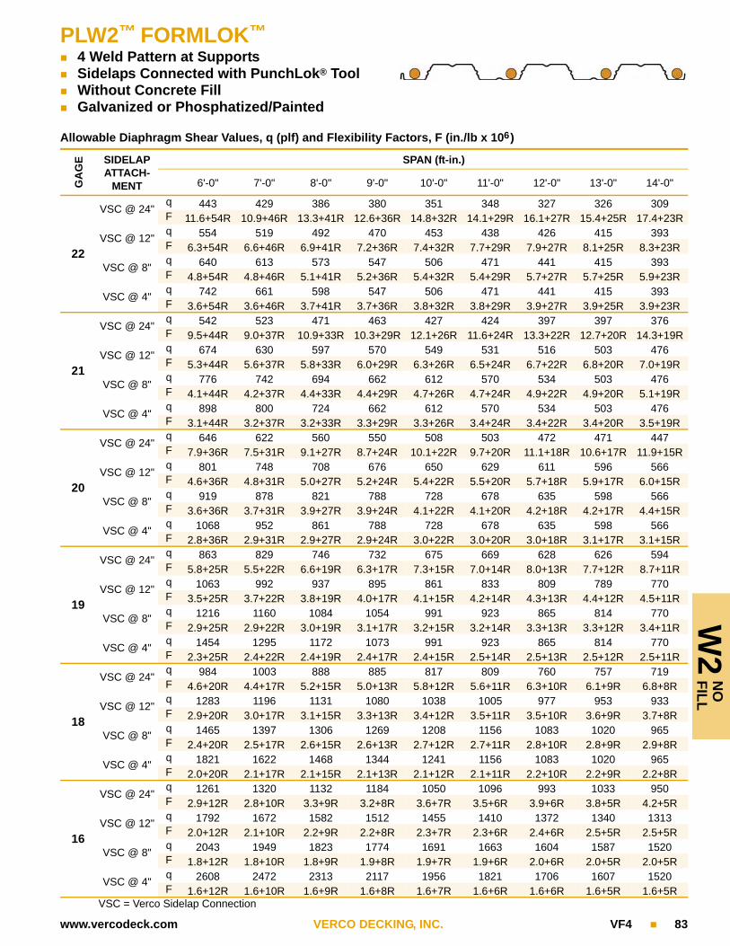
W2
FIL
LN
O
PLW2™ FORMLOK™
4 Weld Pattern at Supports Sidelaps Connected with PunchLok® Tool Without Concrete Fill Galvanized or Phosphatized/Painted
www.vercodeck.com VERCO DECKING, INC. VF4 83
Allowable Diaphragm Shear Values, q (plf) and Flexibility Factors, F (in./lb x 106)
GA
GE SIDELAP
ATTACH-MENT
SPAN (ft-in.)
6'-0" 7'-0" 8'-0" 9'-0" 10'-0" 11'-0" 12'-0" 13'-0" 14'-0"
22
VSC @ 24"q 443 429 386 380 351 348 327 326 309F 11.6+54R 10.9+46R 13.3+41R 12.6+36R 14.8+32R 14.1+29R 16.1+27R 15.4+25R 17.4+23R
VSC @ 12"q 554 519 492 470 453 438 426 415 393F 6.3+54R 6.6+46R 6.9+41R 7.2+36R 7.4+32R 7.7+29R 7.9+27R 8.1+25R 8.3+23R
VSC @ 8"q 640 613 573 547 506 471 441 415 393F 4.8+54R 4.8+46R 5.1+41R 5.2+36R 5.4+32R 5.4+29R 5.7+27R 5.7+25R 5.9+23R
VSC @ 4"q 742 661 598 547 506 471 441 415 393F 3.6+54R 3.6+46R 3.7+41R 3.7+36R 3.8+32R 3.8+29R 3.9+27R 3.9+25R 3.9+23R
21
VSC @ 24"q 542 523 471 463 427 424 397 397 376F 9.5+44R 9.0+37R 10.9+33R 10.3+29R 12.1+26R 11.6+24R 13.3+22R 12.7+20R 14.3+19R
VSC @ 12"q 674 630 597 570 549 531 516 503 476F 5.3+44R 5.6+37R 5.8+33R 6.0+29R 6.3+26R 6.5+24R 6.7+22R 6.8+20R 7.0+19R
VSC @ 8"q 776 742 694 662 612 570 534 503 476F 4.1+44R 4.2+37R 4.4+33R 4.4+29R 4.7+26R 4.7+24R 4.9+22R 4.9+20R 5.1+19R
VSC @ 4"q 898 800 724 662 612 570 534 503 476F 3.1+44R 3.2+37R 3.2+33R 3.3+29R 3.3+26R 3.4+24R 3.4+22R 3.4+20R 3.5+19R
20
VSC @ 24"q 646 622 560 550 508 503 472 471 447F 7.9+36R 7.5+31R 9.1+27R 8.7+24R 10.1+22R 9.7+20R 11.1+18R 10.6+17R 11.9+15R
VSC @ 12"q 801 748 708 676 650 629 611 596 566F 4.6+36R 4.8+31R 5.0+27R 5.2+24R 5.4+22R 5.5+20R 5.7+18R 5.9+17R 6.0+15R
VSC @ 8"q 919 878 821 788 728 678 635 598 566F 3.6+36R 3.7+31R 3.9+27R 3.9+24R 4.1+22R 4.1+20R 4.2+18R 4.2+17R 4.4+15R
VSC @ 4"q 1068 952 861 788 728 678 635 598 566F 2.8+36R 2.9+31R 2.9+27R 2.9+24R 3.0+22R 3.0+20R 3.0+18R 3.1+17R 3.1+15R
19
VSC @ 24"q 863 829 746 732 675 669 628 626 594F 5.8+25R 5.5+22R 6.6+19R 6.3+17R 7.3+15R 7.0+14R 8.0+13R 7.7+12R 8.7+11R
VSC @ 12"q 1063 992 937 895 861 833 809 789 770F 3.5+25R 3.7+22R 3.8+19R 4.0+17R 4.1+15R 4.2+14R 4.3+13R 4.4+12R 4.5+11R
VSC @ 8"q 1216 1160 1084 1054 991 923 865 814 770F 2.9+25R 2.9+22R 3.0+19R 3.1+17R 3.2+15R 3.2+14R 3.3+13R 3.3+12R 3.4+11R
VSC @ 4"q 1454 1295 1172 1073 991 923 865 814 770F 2.3+25R 2.4+22R 2.4+19R 2.4+17R 2.4+15R 2.5+14R 2.5+13R 2.5+12R 2.5+11R
18
VSC @ 24"q 984 1003 888 885 817 809 760 757 719F 4.6+20R 4.4+17R 5.2+15R 5.0+13R 5.8+12R 5.6+11R 6.3+10R 6.1+9R 6.8+8R
VSC @ 12"q 1283 1196 1131 1080 1038 1005 977 953 933F 2.9+20R 3.0+17R 3.1+15R 3.3+13R 3.4+12R 3.5+11R 3.5+10R 3.6+9R 3.7+8R
VSC @ 8"q 1465 1397 1306 1269 1208 1156 1083 1020 965F 2.4+20R 2.5+17R 2.6+15R 2.6+13R 2.7+12R 2.7+11R 2.8+10R 2.8+9R 2.9+8R
VSC @ 4"q 1821 1622 1468 1344 1241 1156 1083 1020 965F 2.0+20R 2.1+17R 2.1+15R 2.1+13R 2.1+12R 2.1+11R 2.2+10R 2.2+9R 2.2+8R
16
VSC @ 24"q 1261 1320 1132 1184 1050 1096 993 1033 950F 2.9+12R 2.8+10R 3.3+9R 3.2+8R 3.6+7R 3.5+6R 3.9+6R 3.8+5R 4.2+5R
VSC @ 12"q 1792 1672 1582 1512 1455 1410 1372 1340 1313F 2.0+12R 2.1+10R 2.2+9R 2.2+8R 2.3+7R 2.3+6R 2.4+6R 2.5+5R 2.5+5R
VSC @ 8"q 2043 1949 1823 1774 1691 1663 1604 1587 1520F 1.8+12R 1.8+10R 1.8+9R 1.9+8R 1.9+7R 1.9+6R 2.0+6R 2.0+5R 2.0+5R
VSC @ 4"q 2608 2472 2313 2117 1956 1821 1706 1607 1520F 1.6+12R 1.6+10R 1.6+9R 1.6+8R 1.6+7R 1.6+6R 1.6+6R 1.6+5R 1.6+5R
VSC = Verco Sidelap Connection

W3 FORMLOK™
4 Weld Pattern at Supports Button Punch, Screw, or 1½" Top Seam Weld Without Concrete Fill Galvanized or Phosphatized/Painted
W3
NO
FIL
L
84 VF4 VERCO DECKING, INC. www.vercodeck.com
Allowable Diaphragm Shear Values, q (plf) and Flexibility Factors, F (in./lb x 106)
GA
GE SIDELAP
ATTACH-MENT
SPAN (ft-in.)
6'-0" 7'-0" 8'-0" 9'-0" 10'-0" 11'-0" 12'-0" 14'-0" 16'-0"
22
BP @ 24"q 155 145 127 123 111 109 100 93 87F 15.4+410R 16.5+351R 18.7+308R 19.6+273R 21.7+246R 22.3+224R 24.4+205R 26.9+176R 29.2+154R
BP @ 12"q 196 180 169 160 153 148 143 137 132F 12.8+410R 13.8+351R 14.8+308R 15.7+273R 16.5+246R 17.2+224R 17.9+205R 19.2+176R 20.3+154R
TSW @ 24"q 194 195 170 173 156 160 146 139 134F 11.0+410R 9.9+351R 9.9+308R 9.1+273R 9.2+246R 8.5+224R 8.6+205R 8.1+176R 7.7+154R
TSW @ 12"q 296 283 272 264 258 252 248 241 236F 8.2+410R 7.7+351R 7.3+308R 7.0+273R 6.7+246R 6.4+224R 6.2+205R 5.9+176R 5.6+154R
21
BP @ 24"q 211 195 171 163 147 143 131 121 113F 13.0+278R 14.1+239R 15.9+209R 16.9+186R 18.7+167R 19.5+152R 21.3+139R 23.7+119R 26.0+104R
BP @ 12"q 257 235 218 206 195 187 181 171 164F 11.1+278R 12.1+239R 13.0+209R 13.9+186R 14.7+167R 15.4+152R 16.2+139R 17.5+119R 18.7+104R
TSW @ 24"q 275 272 237 239 214 218 199 189 181F 9.5+278R 8.6+239R 8.7+209R 8.0+186R 8.1+167R 7.5+152R 7.6+139R 7.2+119R 6.9+104R
TSW @ 12"q 407 385 369 357 347 339 332 321 313F 7.2+278R 6.8+239R 6.5+209R 6.2+186R 6.0+167R 5.8+152R 5.6+139R 5.3+119R 5.0+104R
20
BP @ 24"q 243 223 195 185 167 162 149 136 127F 11.9+233R 13.0+200R 14.8+175R 15.7+155R 17.4+140R 18.2+127R 19.9+117R 22.3+100R 24.6+87R
BP @ 12"q 292 265 246 231 219 209 201 190 181F 10.3+233R 11.3+200R 12.2+175R 13.1+155R 13.9+140R 14.7+127R 15.4+117R 16.7+100R 17.9+87R
TSW @ 24"q 322 317 276 277 248 252 230 217 208F 8.8+233R 8.1+200R 8.1+175R 7.5+155R 7.6+140R 7.1+127R 7.2+117R 6.8+100R 6.5+87R
TSW @ 12"q 471 444 425 410 397 387 379 366 357F 6.8+233R 6.4+200R 6.1+175R 5.9+155R 5.6+140R 5.5+127R 5.3+117R 5.0+100R 4.8+87R
19
BP @ 24"q 372 336 295 276 249 239 219 198 183F 9.2+135R 10.2+116R 11.5+101R 12.4+90R 13.8+81R 14.6+74R 16.1+67R 18.2+58R 20.3+51R
BP @ 12"q 430 387 355 330 310 295 282 262 248F 8.2+135R 9.1+116R 9.9+101R 10.7+90R 11.5+81R 12.2+74R 12.9+67R 14.3+58R 15.5+51R
TSW @ 24"q 528 510 444 440 394 395 361 337 320F 7.1+135R 6.5+116R 6.6+101R 6.2+90R 6.3+81R 5.9+74R 6.0+67R 5.7+58R 5.5+51R
TSW @ 12"q 742 694 658 630 608 590 575 551 534F 5.6+135R 5.3+116R 5.1+101R 4.9+90R 4.8+81R 4.6+74R 4.5+67R 4.3+58R 4.1+51R
18
BP @ 24"q 478 429 376 350 316 300 276 248 227F 7.8+96R 8.7+83R 9.8+72R 10.7+64R 11.9+58R 12.7+53R 13.9+48R 15.9+41R 17.9+36R
BP @ 12"q 542 484 442 409 383 362 345 318 299F 7.1+96R 7.9+83R 8.7+72R 9.4+64R 10.1+58R 10.8+53R 11.5+48R 12.8+41R 14.0+36R
TSW @ 24"q 663 643 566 564 511 515 476 442 417F 6.1+96R 5.7+83R 5.8+72R 5.5+64R 5.5+58R 5.2+53R 5.3+48R 5.1+41R 4.9+36R
TSW @ 12"q 912 859 822 794 773 756 744 710 685F 4.9+96R 4.7+83R 4.5+72R 4.4+64R 4.3+58R 4.1+53R 4.0+48R 3.8+41R 3.7+36R
16
BP @ 24"q 752 667 585 538 486 457 420 374 340F 5.6+49R 6.2+42R 7.1+37R 7.8+32R 8.7+29R 9.4+27R 10.3+24R 11.9+21R 13.6+18R
BP @ 12"q 826 732 662 608 565 530 502 458 426F 5.2+49R 5.8+42R 6.4+37R 7.0+32R 7.7+29R 8.3+27R 8.9+24R 10.0+21R 11.2+18R
TSW @ 24"q 1003 958 844 830 752 752 694 656 629F 4.5+49R 4.3+42R 4.4+37R 4.2+32R 4.2+29R 4.0+27R 4.1+24R 4.0+21R 3.9+18R
TSW @ 12"q 1327 1241 1179 1133 1098 1071 1050 1021 1003F 3.8+49R 3.6+42R 3.5+37R 3.4+32R 3.3+29R 3.3+27R 3.2+24R 3.1+21R 3.0+18R
BP = Button Punch; TSW = Top Seam Weld; Screw may be substituted for BP at same spacing, see page 12 for add’l info.

W3
FIL
LN
O
PLW3™ FORMLOK™
4 Weld Pattern at Supports Sidelaps Connected with PunchLok® Tool Without Concrete Fill Galvanized or Phosphatized/Painted
www.vercodeck.com VERCO DECKING, INC. VF4 85
Allowable Diaphragm Shear Values, q (plf) and Flexibility Factors, F (in./lb x 106)
GA
GE SIDELAP
ATTACH-MENT
SPAN (ft-in.)
6'-0" 7'-0" 8'-0" 9'-0" 10'-0" 11'-0" 12'-0" 14'-0" 16'-0"
22
VSC @ 24"q 389 377 339 335 309 307 288 272 261F 12.0+85R 11.2+73R 13.7+64R 12.9+57R 15.2+51R 14.4+46R 16.5+42R 17.8+36R 18.9+32R
VSC @ 12"q 489 458 434 415 400 387 376 359 346F 6.5+85R 6.8+73R 7.1+64R 7.4+57R 7.6+51R 7.9+46R 8.1+42R 8.5+36R 8.9+32R
VSC @ 8"q 566 542 507 494 470 462 444 413 374F 5.0+85R 5.0+73R 5.3+64R 5.3+57R 5.6+51R 5.6+46R 5.8+42R 6.1+36R 6.3+32R
VSC @ 4"q 739 695 629 576 532 495 464 413 374F 3.7+85R 3.7+73R 3.8+64R 3.8+57R 3.9+51R 3.9+46R 4.0+42R 4.0+36R 4.1+32R
21
VSC @ 24"q 514 497 447 440 406 403 377 357 342F 9.2+63R 8.7+54R 10.5+48R 10.0+42R 11.7+38R 11.1+35R 12.7+32R 13.7+27R 14.6+24R
VSC @ 12"q 642 600 568 543 522 505 491 468 451F 5.2+63R 5.4+54R 5.7+48R 5.9+42R 6.1+38R 6.3+35R 6.4+32R 6.8+27R 7.1+24R
VSC @ 8"q 739 707 661 643 611 600 578 535 484F 4.1+63R 4.1+54R 4.3+48R 4.3+42R 4.5+38R 4.6+35R 4.7+32R 4.9+27R 5.1+24R
VSC @ 4"q 960 900 814 745 689 641 601 535 484F 3.1+63R 3.2+54R 3.2+48R 3.2+42R 3.3+38R 3.3+35R 3.4+32R 3.4+27R 3.5+24R
20
VSC @ 24"q 582 561 505 496 457 454 425 402 385F 8.1+56R 7.7+48R 9.3+42R 8.9+37R 10.3+33R 9.9+30R 11.3+28R 12.1+24R 13.0+21R
VSC @ 12"q 723 676 639 611 587 568 552 526 507F 4.7+56R 4.9+48R 5.1+42R 5.3+37R 5.5+33R 5.6+30R 5.8+28R 6.1+24R 6.4+21R
VSC @ 8"q 832 795 743 722 687 674 649 602 545F 3.7+56R 3.7+48R 3.9+42R 4.0+37R 4.1+33R 4.2+30R 4.3+28R 4.5+24R 4.6+21R
VSC @ 4"q 1077 1012 916 838 775 721 676 602 545F 2.9+56R 2.9+48R 3.0+42R 3.0+37R 3.0+33R 3.1+30R 3.1+28R 3.2+24R 3.2+21R
19
VSC @ 24"q 831 798 718 704 650 643 603 570 545F 5.6+37R 5.4+32R 6.4+28R 6.1+25R 7.1+22R 6.8+20R 7.7+18R 8.3+16R 8.9+14R
VSC @ 12"q 1025 955 903 862 828 801 778 742 715F 3.5+37R 3.6+32R 3.7+28R 3.9+25R 4.0+22R 4.1+20R 4.2+18R 4.4+16R 4.6+14R
VSC @ 8"q 1173 1119 1045 1015 965 947 912 867 784F 2.8+37R 2.9+32R 3.0+28R 3.0+25R 3.1+22R 3.1+20R 3.3+18R 3.4+16R 3.5+14R
VSC @ 4"q 1508 1427 1319 1207 1115 1039 973 867 784F 2.3+37R 2.3+32R 2.4+28R 2.4+25R 2.4+22R 2.4+20R 2.5+18R 2.5+16R 2.5+14R
18
VSC @ 24"q 982 973 875 857 791 783 735 694 664F 4.5+29R 4.3+25R 5.1+21R 4.9+19R 5.6+17R 5.4+16R 6.1+14R 6.6+12R 7.0+11R
VSC @ 12"q 1245 1160 1096 1046 1006 972 945 901 869F 2.9+29R 3.0+25R 3.1+21R 3.2+19R 3.3+17R 3.4+16R 3.5+14R 3.6+12R 3.8+11R
VSC @ 8"q 1422 1356 1266 1229 1170 1148 1106 1060 982F 2.4+29R 2.4+25R 2.5+21R 2.6+19R 2.6+17R 2.7+16R 2.7+14R 2.8+12R 2.9+11R
VSC @ 4"q 1823 1724 1649 1512 1397 1301 1218 1085 982F 2.0+29R 2.0+25R 2.1+21R 2.1+19R 2.1+17R 2.1+16R 2.1+14R 2.2+12R 2.2+11R
16
VSC @ 24"q 1265 1325 1136 1189 1054 1100 997 955 922F 2.9+17R 2.8+15R 3.2+13R 3.1+11R 3.5+10R 3.4+9R 3.8+9R 4.1+7R 4.4+6R
VSC @ 12"q 1761 1641 1551 1481 1425 1379 1341 1281 1238F 2.0+17R 2.1+15R 2.1+13R 2.2+11R 2.3+10R 2.3+9R 2.4+9R 2.5+7R 2.6+6R
VSC @ 8"q 2006 1912 1787 1737 1655 1625 1567 1505 1460F 1.8+17R 1.8+15R 1.8+13R 1.8+11R 1.9+10R 1.9+9R 2.0+9R 2.0+7R 2.1+6R
VSC @ 4"q 2561 2424 2320 2239 2174 2049 1920 1710 1547F 1.6+17R 1.6+15R 1.6+13R 1.6+11R 1.6+10R 1.6+9R 1.6+9R 1.6+7R 1.7+6R
VSC = Verco Sidelap Connection

VE
RC
OR
™
86 VF4 VERCO DECKING, INC. www.vercodeck.com
VERCOR™ FORM DECK TECHNICAL DATA
Material Deep and Shallow VERCOR form decks are fabricated from G90 galva-nized steel conforming to ASTM A 653 or A 1063, SS Grade 80.
Galvanized VERCOR deck can be considered as a permanent form. Uncoated decks should not be considered permanent forms; therefore, the reinforced slab should be designed for the total load. Uncoated deck is available only as a special order.
Uniform Load Tables The tables on pages 88 and 90 list the allowable uniform loads. These are the total uniform loads which can be applied to the VERCOR form deck. Values are based on the allowable bending moment (stress), and on limiting deflection to either L/240 or L/180. The symbol ♦♦♦ indicates that the allowable uniform load based on deflection exceeds the allowable load based on flexure (stress). Note that self-weight of the deck should be included when determining dead load.
The formulas used to determine the allowable uniform loads due to stress and deflection are as follows:
Allowable Unshored Span Tables
The maximum allowable unshored spans shown on pages 89 and 91 are based on the loading criteria for deck as a form as discussed beginning on page 14 of this catalog. These spans are maximum clear spans.
The dead load for determination of the allowable unshored spans is the total of the concrete weight plus deck weight plus deck deflection allow-ance. The following allowances for VERCOR deck deflection are included:• 3 psf for light weight concrete.• 4 psf for normal weight concrete.No allowance is included for deflection of structural supports.
VERCOR Attachment to Supports
Welding VERCOR decks lighter than 22 gage requires weld washers in accordance with AWS D1.3 (see Figure 21).
Span Bending Moment Deflection
Single
Double
Triple
where E = 29.5 x 10⁶ psi
+M 0.125 w L 2= 0.013 w L 4 1728E Id glesin
----------------------------------------------------=
M– 0.125 w L 2= 0.0054 w L4 1728 E Id mult
-------------------------------------------------------=
M– 0.1 w L 2= 0.0069 w L4 1728 E Id mult
-------------------------------------------------------=
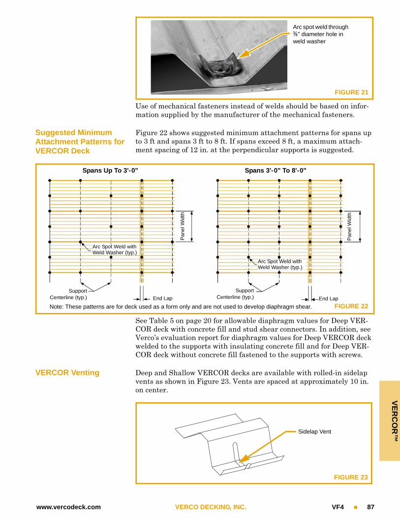
VE
RC
OR
™
www.vercodeck.com VERCO DECKING, INC. VF4 87
Use of mechanical fasteners instead of welds should be based on infor-mation supplied by the manufacturer of the mechanical fasteners.
Suggested Minimum Attachment Patterns for VERCOR Deck
Figure 22 shows suggested minimum attachment patterns for spans up to 3 ft and spans 3 ft to 8 ft. If spans exceed 8 ft, a maximum attach-ment spacing of 12 in. at the perpendicular supports is suggested.
See Table 5 on page 20 for allowable diaphragm values for Deep VER-COR deck with concrete fill and stud shear connectors. In addition, see Verco’s evaluation report for diaphragm values for Deep VERCOR deck welded to the supports with insulating concrete fill and for Deep VER-COR deck without concrete fill fastened to the supports with screws.
VERCOR Venting Deep and Shallow VERCOR decks are available with rolled-in sidelap vents as shown in Figure 23. Vents are spaced at approximately 10 in. on center.
FIGURE 21
Arc spot weld through 3-i" diameter hole in weld washer
FIGURE 22
Spans Up To 3'-0" Spans 3'-0" To 8'-0"
SupportCenterline (typ.) End Lap
Arc Spot Weld with Weld Washer (typ.)
Arc Spot Weld with Weld Washer (typ.)
End Lap
Pan
el W
idth
Pan
el W
idth
Note: These patterns are for deck used as a form only and are not used to develop diaphragm shear.
SupportCenterline (typ.)
FIGURE 23
Sidelap Vent

VE
RC
OR
™
88 VF4 VERCO DECKING, INC. www.vercodeck.com
Deep VERCOR™
15_qy in. Non-Composite Form Deck Galvanized
Deck Weight and Section Properties
Gage
Weight Id for Deflection Moment Allowable Reactions per ft of Width (lb)
Galv
(psf )
Single Span
(in.4/ft)
Multiple Spans
(in.4/ft)
+Seff
(in.3/ft)
–Seff
(in.3/ft)
End Bearing Interior Bearing
2" 3" 4" 3" 4"
26 1.1 0.075 0.075 0.099 0.103 492 572 639 829 916
24 1.4 0.097 0.097 0.137 0.138 802 927 1032 1366 1503
22 1.7 0.120 0.120 0.172 0.171 1184 1361 1510 2029 2225
20 2.1 0.143 0.143 0.204 0.204 1628 1864 2064 2807 3069
Note: Section properties are based on Fy = 60,000 psi (specified minimum Fy = 80,000 psi).
Allowable Uniform Loads (psf)
GageSpan (ft-in.)
3'-0" 3'-6" 4'-0" 4'-6" 5'-0" 5'-6" 6'-0" 6'-6" 7'-0" 7'-6" 8'-0" 8'-6" 9'-0" 9'-6" 10'-0"Single Span
26
Stress 264 194 149 117 95 79 66 56 48 42
L/240 182 115 77 54 39 30 23 18 14 12
L/180 243 153 103 72 53 39 30 24 19 16
24
Stress 300 268 206 162 132 109 91 78 67 58 51
L/240 236 149 100 70 51 38 29 23 19 15 12
L/180 ♦♦♦ 198 133 93 68 51 39 31 25 20 17
22
Stress 300 300 258 204 165 136 115 98 84 73 65 57 51
L/240 292 184 123 86 63 47 36 29 23 19 15 13 11
L/180 ♦♦♦ 245 164 115 84 63 49 38 31 25 21 17 14
20
Stress 300 300 300 242 196 162 136 116 100 87 77 68 60 54
L/240 ♦♦♦ 219 147 103 75 56 43 34 27 22 18 15 13 11
L/180 ♦♦♦ 292 196 137 100 75 58 46 36 30 24 20 17 15
Double Span
26
Stress 275 202 155 122 99 82 69 59 50 44 39 34 31 27
L/240 ♦♦♦ ♦♦♦ ♦♦♦ ♦♦♦ 95 71 55 43 35 28 23 19 16 14
L/180 ♦♦♦ ♦♦♦ ♦♦♦ ♦♦♦ ♦♦♦ ♦♦♦ ♦♦♦ 58 46 37 31 26 22 18
24
Stress 300 270 207 164 132 109 92 78 68 59 52 46 41 37 33
L/240 ♦♦♦ ♦♦♦ ♦♦♦ ♦♦♦ 123 92 71 56 45 36 30 25 21 18 15
L/180 ♦♦♦ ♦♦♦ ♦♦♦ ♦♦♦ ♦♦♦ ♦♦♦ ♦♦♦ 74 60 48 40 33 28 24 20
22
Stress 300 300 257 203 164 136 114 97 84 73 64 57 51 45 41
L/240 ♦♦♦ ♦♦♦ ♦♦♦ ♦♦♦ 152 114 88 69 55 45 37 31 26 22 19
L/180 ♦♦♦ ♦♦♦ ♦♦♦ ♦♦♦ ♦♦♦ ♦♦♦ ♦♦♦ 92 74 60 49 41 35 29 25
20
Stress 300 300 300 242 196 162 136 116 100 87 77 68 60 54 49
L/240 ♦♦♦ ♦♦♦ ♦♦♦ ♦♦♦ 181 136 105 82 66 54 44 37 31 26 23
L/180 ♦♦♦ ♦♦♦ ♦♦♦ ♦♦♦ ♦♦♦ ♦♦♦ ♦♦♦ 110 88 71 59 49 41 35 30
Triple Span
26
Stress 300 252 193 153 124 102 86 73 63 55 48 43 38 34 31
L/240 ♦♦♦ 216 145 102 74 56 43 34 27 22 18 15 13 11 9
L/180 ♦♦♦ ♦♦♦ ♦♦♦ 136 99 74 57 45 36 29 24 20 17 14 12
24
Stress 300 300 259 204 166 137 115 98 84 74 65 57 51 46 41
L/240 ♦♦♦ 280 187 132 96 72 56 44 35 28 23 20 16 14 12
L/180 ♦♦♦ ♦♦♦ 250 176 128 96 74 58 47 38 31 26 22 19 16
(Continued on following page)

VE
RC
OR
™Deep VERCOR™
15_qy in. Non-Composite Form Deck Galvanized
www.vercodeck.com VERCO DECKING, INC. VF4 89
Triple Span (continued)
22
Stress 300 300 300 253 205 170 143 121 105 91 80 71 63 57 51
L/240 ♦♦♦ ♦♦♦ 232 163 119 89 69 54 43 35 29 24 20 17 15
L/180 ♦♦♦ ♦♦♦ ♦♦♦ 217 158 119 92 72 58 47 39 32 27 23 20
20
Stress 300 300 300 300 245 202 170 145 125 109 96 85 76 68 61
L/240 ♦♦♦ ♦♦♦ 276 194 142 106 82 64 52 42 35 29 24 21 18
L/180 ♦♦♦ ♦♦♦ ♦♦♦ 259 189 142 109 86 69 56 46 38 32 28 24
Notes:1. Stress = Uniform load which produces maximum allowable stress in deck.2. L/240 = Uniform load which produces L/240 deflection in deck. L/180 = Uniform load which produces L/180 deflection in deck.3. Self-weight of the deck should be included when determining dead load.4. The symbol ♦♦♦ indicates allowable uniform load based on deflection exceeds allowable uniform load based on stress.
Maximum Allowable Unshored Clear Spans (ft-in.)
TotalSlab
Depth
Normal Weight Concrete - 145 pcf Light Weight Concrete - 110 pcf
Concrete Weight
Gage 1 Span 2 Span 3 SpanConcrete Weight
Gage 1 Span 2 Span 3 Span
3½" 34.4 psf
26 4'-10" 5'-8" 5'-9"
26.1 psf
26 5'-2" 6'-1" 6'-2"
24 5'-11" 7'-1" 7'-2" 24 6'-6" 7'-9" 7'-10"
22 6'-4" 8'-3" 7'-10" 22 6'-11" 8'-11" 8'-7"
20 6'-9" 8'-11" 8'-4" 20 7'-4" 9'-9" 9'-1"
4" 40.4 psf
26 4'-7" 5'-5" 5'-6"
30.7 psf
26 5'-0" 5'-11" 5'-11"
24 5'-8" 6'-9" 6'-10" 24 6'-2" 7'-5" 7'-6"
22 6'-1" 7'-10" 7'-6" 22 6'-8" 8'-7" 8'-2"
20 6'-5" 8'-6" 7'-11" 20 7'-0" 9'-4" 8'-8"
4½" 46.4 psf
26 4'-5" 5'-3" 5'-3"
35.2 psf
26 4'-10" 5'-8" 5'-9"
24 5'-5" 6'-6" 6'-7" 24 5'-11" 7'-1" 7'-2"
22 5'-10" 7'-6" 7'-2" 22 6'-5" 8'-3" 7'-10"
20 6'-2" 8'-2" 7'-7" 20 6'-9" 9'-0" 8'-4"
5" 52.5 psf
26 4'-3" 5'-0" 5'-1"
39.8 psf
26 4'-8" 5'-6" 5'-7"
24 5'-3" 6'-3" 6'-4" 24 5'-9" 6'-10" 6'-11"
22 5'-7" 7'-3" 6'-11" 22 6'-2" 7'-11" 7'-7"
20 5'-11" 7'-10" 7'-4" 20 6'-6" 8'-8" 8'-0"
5½" 58.5 psf
26 4'-2" 4'-11" 4'-11"
44.4 psf
26 4'-6" 5'-4" 5'-5"
24 5'-1" 6'-0" 6'-1" 24 5'-7" 6'-8" 6'-9"
22 5'-5" 6'-11" 6'-9" 22 5'-11" 7'-8" 7'-4"
20 5'-9" 7'-7" 7'-1" 20 6'-3" 8'-4" 7'-9"
6" 64.6 psf
26 4'-0" 4'-9" 4'-9"
49.0 psf
26 4'-5" 5'-2" 5'-3"
24 4'-11" 5'-10" 5'-11" 24 5'-5" 6'-5" 6'-6"
22 5'-3" 6'-9" 6'-6" 22 5'-9" 7'-5" 7'-2"
20 5'-7" 7'-4" 6'-11" 20 6'-1" 8'-1" 7'-6"
6½" 70.6 psf
26 3'-11" 4'-7" 4'-8"
53.6 psf
26 4'-3" 5'-0" 5'-1"
24 4'-9" 5'-8" 5'-9" 24 5'-3" 6'-3" 6'-4"
22 5'-2" 6'-6" 6'-4" 22 5'-7" 7'-2" 6'-11"
20 5'-5" 7'-1" 6'-9" 20 5'-11" 7'-10" 7'-4"
Allowable Uniform Loads (psf) (continued)
GageSpan (ft-in.)
3'-0" 3'-6" 4'-0" 4'-6" 5'-0" 5'-6" 6'-0" 6'-6" 7'-0" 7'-6" 8'-0" 8'-6" 9'-0" 9'-6" 10'-0"

VE
RC
OR
™
Shallow VERCOR™
9_qy in. Non-Composite Form Deck Galvanized
90 VF4 VERCO DECKING, INC. www.vercodeck.com
Deck Weight and Section Properties
Gage
Weight Id for Deflection Moment Allowable Reactions per ft of Width (lb)
Galv
(psf )
Single Span
(in.4/ft)
Multiple Spans
(in.4/ft)
+Seff
(in.3/ft)
–Seff
(in.3/ft)
End Bearing Interior Bearing
1½" 2" 1½" 2"
26 1.0 0.013 0.013 0.041 0.043 581 644 788 862
24 1.3 0.018 0.018 0.059 0.059 980 1081 1375 1497
22 1.6 0.022 0.022 0.073 0.073 1466 1611 2105 2283
Note: Section properties are based on Fy = 60,000 psi (specified minimum Fy = 80,000 psi).
Allowable Uniform Loads (psf)
GageSpan (ft-in.)
1'-0" 1'-6" 2'-0" 2'-6" 3'-0" 3'-6" 4'-0" 4'-6" 5'-0" 5'-6" 6'-0"
Single Span
26
Stress 300 300 246 157 109 80
L/240 ♦♦♦ 253 107 55 32 20
L/180 ♦♦♦ ♦♦♦ 142 73 42 27
24
Stress 300 300 300 227 157 116 89 70
L/240 ♦♦♦ ♦♦♦ 148 76 44 28 18 13
L/180 ♦♦♦ ♦♦♦ 197 101 58 37 25 17
22
Stress 300 300 300 280 195 143 110 87 70
L/240 ♦♦♦ ♦♦♦ 181 92 54 34 23 16 12
L/180 ♦♦♦ ♦♦♦ 241 123 71 45 30 21 15
Double Span
26
Stress 300 300 258 165 115 84 65 51
L/240 ♦♦♦ ♦♦♦ 257 132 76 48 32 23
L/180 ♦♦♦ ♦♦♦ ♦♦♦ ♦♦♦ 101 64 43 30
24
Stress 300 300 300 227 157 116 89 70 57 47 39
L/240 ♦♦♦ ♦♦♦ ♦♦♦ 182 105 66 44 31 23 17 13
L/180 ♦♦♦ ♦♦♦ ♦♦♦ ♦♦♦ 141 88 59 42 30 23 18
22
Stress 300 300 300 280 195 143 110 87 70 58 49
L/240 ♦♦♦ ♦♦♦ ♦♦♦ 223 129 81 54 38 28 21 16
L/180 ♦♦♦ ♦♦♦ ♦♦♦ ♦♦♦ 172 108 72 51 37 28 21
Triple Span
26
Stress 300 300 300 206 143 105 81 64
L/240 ♦♦♦ ♦♦♦ 201 103 60 38 25 18
L/180 ♦♦♦ ♦♦♦ 268 137 79 50 34 24
24
Stress 300 300 300 283 197 144 111 87 71 59 49
L/240 ♦♦♦ ♦♦♦ 278 143 82 52 35 24 18 13 10
L/180 ♦♦♦ ♦♦♦ ♦♦♦ 190 110 69 46 33 24 18 14
22
Stress 300 300 300 300 243 179 137 108 88 72 61
L/240 ♦♦♦ ♦♦♦ ♦♦♦ 174 101 63 43 30 22 16 13
L/180 ♦♦♦ ♦♦♦ ♦♦♦ 232 134 85 57 40 29 22 17
Notes:1. Stress = Uniform load which produces maximum allowable stress in deck.2. L/240 = Uniform load which produces L/240 deflection in deck. L/180 = Uniform load which produces L/180 deflection in deck.3. Self-weight of the deck should be included when determining dead load.4. The symbol ♦♦♦ indicates allowable uniform load based on deflection exceeds allowable uniform load based on stress.
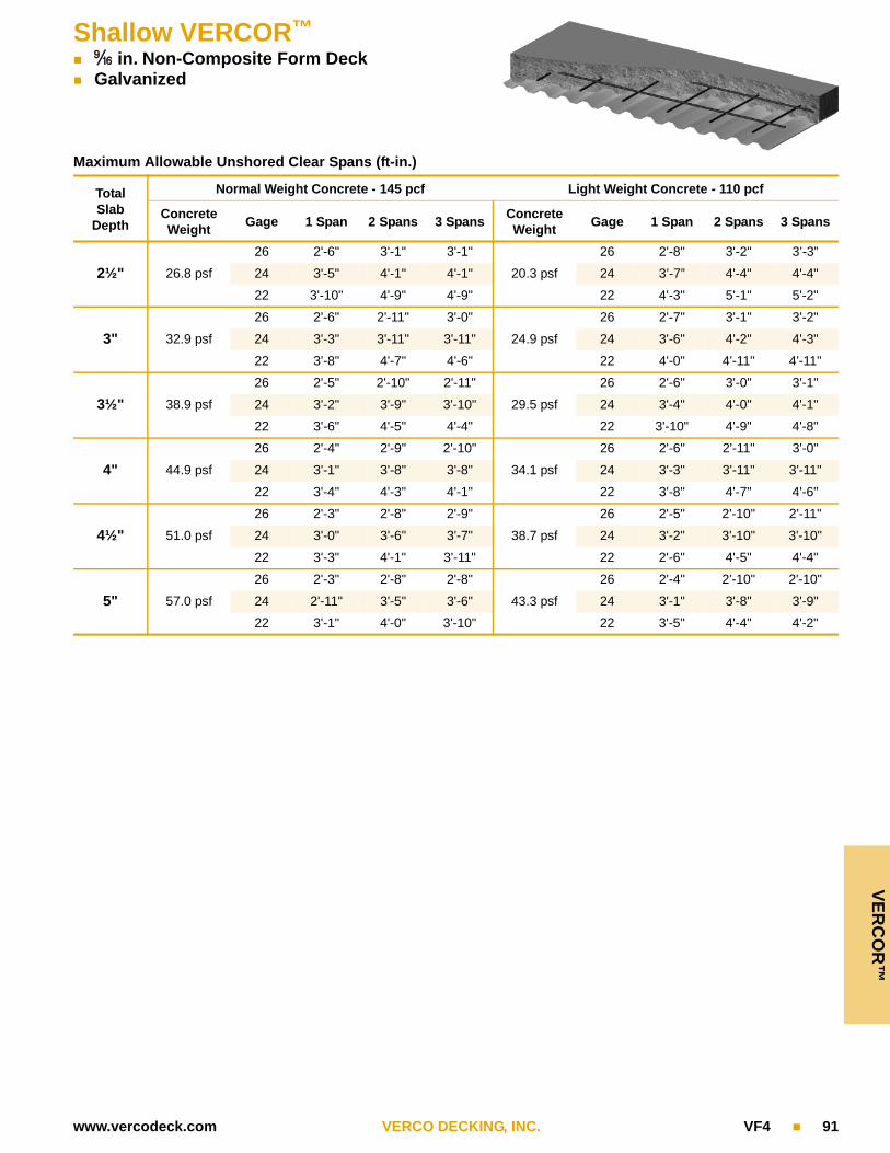
VE
RC
OR
™Shallow VERCOR™
9_qy in. Non-Composite Form Deck Galvanized
www.vercodeck.com VERCO DECKING, INC. VF4 91
Maximum Allowable Unshored Clear Spans (ft-in.)
TotalSlab
Depth
Normal Weight Concrete - 145 pcf Light Weight Concrete - 110 pcf
Concrete Weight
Gage 1 Span 2 Spans 3 SpansConcrete Weight
Gage 1 Span 2 Spans 3 Spans
2½" 26.8 psf
26 2'-6" 3'-1" 3'-1"
20.3 psf
26 2'-8" 3'-2" 3’-3”
24 3'-5" 4'-1" 4'-1" 24 3’-7” 4'-4" 4'-4"
22 3'-10" 4'-9" 4'-9" 22 4'-3" 5'-1" 5'-2"
3" 32.9 psf
26 2'-6" 2'-11" 3'-0"
24.9 psf
26 2'-7" 3'-1" 3'-2"
24 3'-3" 3'-11" 3'-11" 24 3'-6" 4'-2" 4'-3"
22 3'-8" 4'-7" 4'-6" 22 4'-0" 4'-11" 4'-11"
3½" 38.9 psf
26 2'-5" 2'-10" 2'-11"
29.5 psf
26 2'-6" 3'-0" 3'-1"
24 3'-2" 3'-9" 3'-10" 24 3'-4" 4'-0" 4'-1"
22 3'-6" 4'-5" 4'-4" 22 3'-10" 4'-9" 4'-8"
4" 44.9 psf
26 2'-4" 2'-9" 2'-10"
34.1 psf
26 2'-6" 2'-11" 3'-0"
24 3'-1" 3'-8" 3'-8" 24 3'-3" 3'-11" 3'-11"
22 3'-4" 4'-3" 4'-1" 22 3'-8" 4'-7" 4'-6"
4½" 51.0 psf
26 2'-3" 2'-8" 2'-9"
38.7 psf
26 2'-5" 2'-10" 2'-11"
24 3'-0" 3'-6" 3'-7" 24 3'-2" 3'-10" 3'-10"
22 3'-3" 4'-1" 3'-11" 22 2'-6" 4'-5" 4'-4"
5" 57.0 psf
26 2'-3" 2'-8" 2'-8"
43.3 psf
26 2'-4" 2'-10" 2'-10"
24 2'-11" 3'-5" 3'-6" 24 3'-1" 3'-8" 3'-9"
22 3'-1" 4'-0" 3'-10" 22 3'-5" 4'-4" 4'-2"

Cel
lula
r F
OR
ML
OK
™
92 VF4 VERCO DECKING, INC. www.vercodeck.com
CELLULAR FORMLOK™ DECK DESIGN INFORMATION
Properties Section properties have been computed in accordance with AISI’s “S100: North American Specification for the Design of Cold-Formed Steel Structural Members.”
Material Cellular FORMLOK deck sections are fabricated from galvanized steel conforming to ASTM A 653 or A 1063, SS Grade 50. The fluted top and flat bottom sections are factory resistance-welded together, creating a strong structural section.
Note: Weld marks will be visible on the flat bottom.
Definitions The gage “xx/yy” of cellular decks is defined as:First number (xx) is the gage of the fluted top section.Second number (yy) is the gage of the flat bottom section.
Id is the effective moment of inertia for deflection for simple or multiple span conditions.
Seff (+ or ) is the effective section modulus.
M (+ or ) is the ASD allowable moment where M = Mn / Ωb, where Ωb= 1.67 and Mn = Fy • Seff (+ or ).
Vertical Shear (V) is the ASD allowable vertical shear strength based on the horizontal shear strength of the resistance welds connecting the top and bottom sections, where V = Vn / Ω, with Ω = 2.35. “END” shear strength values are applicable adjacent to supports where deck is not continuous.“INTERIOR” shear strength values are applicable adjacent to supports where deck is continuous.
Cellular FORMLOK Deck Bearing
Compare end and interior reactions to the allowable reactions for fluted (non-cellular) deck of the same gage as the fluted top section of the cellu-lar deck.
Allowable Superimposed Loads and Diaphragm Values
Allowable superimposed loads and allowable diaphragm shear values and flexibility factors shown in the FORMLOK tables on pages 37–75 for a given concrete type and thickness may be applied to cellular FORM-LOK deck sections with a fluted top section of the same profile and gage, with or without acoustical perforations in the flat bottom section of the cellular deck.
Vent Tabs Factory vent tabs are not available in cellular FORMLOK deck.
Fire Ratings Refer to FORMLOK Composite Slab Fire Resistance Ratings on pages 30–31 for unprotected fire rated assemblies using cellular FORMLOK deck.

Cellu
lar F
OR
ML
OK
™
www.vercodeck.com VERCO DECKING, INC. VF4 93
Acoustical Cellular FORMLOK Deck
Cellular PLB-CD, BCD, PLN-CD, NCD, PLW2-CD, W2CD, PLW3-CD, and W3CD FORMLOK floor decks are available with acoustical perfora-tions in the flat bottom plate. Acoustical deck can provide sound attenua-tion in buildings where the underside of the deck is exposed to the interior. Acoustical perforations are 5-ew-inch in diameter on 7-ew-inch stag-gered centers in bands centered under the top flanges of the fluted top sections. Insulation is factory installed (see Figure 24). Sound absorption information is shown in Table 11. Noise Reduction Coefficient (NRC) val-ues were determined by tests in accordance with ANSI/ASTM C423 con-ducted by Riverbank Acoustical Laboratories. Test reports furnished upon request.
Table 11: Noise Reduction Coefficients for Acoustical Cellular Deck
Profile
Absorption Coefficients Noise Reduction Coefficient125 250 500 1000 2000 4000
PLB-CDor BCD 0.60 0.55 0.80 1.01 0.89 0.66 0.80
PLN–CDor NCD 0.84 0.79 1.16 0.98 0.82 0.60 0.95
PLW2-CDor W2CD 0.59 0.53 0.84 0.87 0.59 0.46 0.70
PLW3-CDor W3CD 0.70 0.67 1.06 0.86 0.63 0.42 0.80
FIGURE 24Acoustical Cellular Deck
Factory InstalledAcoustical Insulation

CELLULAR FORMLOK™C
ellu
lar
FO
RM
LO
K™
94 VF4 VERCO DECKING, INC. www.vercodeck.com
PLB-CD and BCD FORMLOK™
Deck Weight and Section Properties (per ft of width)
Gage
Weight Id for Deflections Positive Moment Negative Moment Vertical Shear
Single Span
Multiple Span
+Seff +M Seff M End Interior
(psf) (in.4) (in.4) (in.3) (in.-kips) (in.3) (in.-kips) (lb) (lb)
20/20 3.6 0.416 0.416 0.279 8.4 0.382 11.4 340 510
20/18 4.1 0.454 0.454 0.287 8.6 0.428 12.8 318 369
20/16 4.5 0.485 0.485 0.293 8.8 0.447 13.4 306 303
18/20 4.1 0.535 0.535 0.417 12.5 0.453 13.6 369 612
18/18 4.6 0.587 0.587 0.428 12.8 0.552 16.5 517 667
18/16 5.1 0.631 0.631 0.437 13.1 0.575 17.2 491 524
16/18 5.3 0.704 0.704 0.587 17.6 0.629 18.8 549 757
16/16 5.8 0.759 0.759 0.599 17.9 0.700 20.9 718 821
Note: Section properties are based on Fy = 50,000 psi.
PLW2-CD and W2CD FORMLOK™
Deck Weight and Section Properties (per ft of width)
Gage
Weight Id for Deflections Positive Moment Negative Moment Vertical Shear
Single Span
Multiple Span
+Seff +M Seff M End Interior
(psf) (in.4) (in.4) (in.3) (in.-kips) (in.3) (in.-kips) (lb) (lb)
20/20 3.4 0.666 0.666 0.363 10.9 0.429 12.8 404 614
20/18 3.8 0.714 0.714 0.372 11.1 0.446 13.3 376 433
20/16 4.3 0.753 0.753 0.377 11.3 0.458 13.7 359 392
18/20 3.9 0.847 0.847 0.526 15.8 0.549 16.4 439 755
18/18 4.3 0.911 0.911 0.536 16.1 0.570 17.1 596 741
18/16 4.8 0.964 0.964 0.544 16.3 0.586 17.5 562 643
16/18 4.9 1.087 1.087 0.704 21.1 0.702 21.0 638 867
16/16 5.4 1.153 1.153 0.714 21.4 0.722 21.6 831 949
Note: Section properties are based on Fy = 50,000 psi.
Refer to pages 92-93 for cellular deck design information.

Cellu
lar F
OR
ML
OK
™CELLULAR FORMLOK™
www.vercodeck.com VERCO DECKING, INC. VF4 95
PLW3-CD and W3CD FORMLOK™
Deck Weight and Section Properties (per ft of width)
Gage
Weight Id for Deflections Positive Moment Negative Moment Vertical Shear
Single Span
Multiple Span
+Seff +M Seff M End Interior
(psf) (in.4) (in.4) (in.3) (in.-kips) (in.3) (in.-kips) (lb) (lb)
20/20 3.6 1.456 1.456 0.542 16.2 0.625 18.7 571 912
20/18 4.0 1.554 1.554 0.541 16.2 0.652 19.5 528 617
20/16 4.5 1.615 1.615 0.566 16.9 0.672 20.1 502 554
18/20 4.1 1.813 1.813 0.852 25.5 0.813 24.3 628 1171
18/18 4.6 1.949 1.949 0.862 25.8 0.846 25.3 869 1144
18/16 5.0 2.062 2.062 0.859 25.7 0.874 26.2 816 956
16/18 5.2 2.315 2.315 1.105 33.1 1.037 31.1 934 1354
16/16 5.7 2.453 2.453 1.123 33.6 1.073 32.1 1206 1406
Note: Section properties are based on Fy = 50,000 psi.
PLN-CD and NCD FORMLOK™
Deck Weight and Section Properties (per ft of width)
Gage
Weight Id for Deflections Positive Moment Negative Moment Vertical Shear
Single Span
Multiple Span
+Seff +M Seff M End Interior
(psf) (in.4) (in.4) (in.3) (in.-kips) (in.3) (in.-kips) (lb) (lb)
20/20 4.1 1.681 1.681 0.518 15.5 0.706 21.2 559 1039
20/18 4.6 1.841 1.841 0.515 15.4 0.909 27.2 522 718
20/16 5.1 1.951 1.951 0.555 16.6 1.022 30.6 500 550
18/20 4.8 2.159 2.159 0.805 24.1 0.852 25.5 608 1253
18/18 5.3 2.369 2.369 0.826 24.7 1.055 31.6 850 1275
18/16 5.8 2.544 2.544 0.843 25.2 1.318 39.5 805 966
16/18 6.1 2.881 2.881 1.121 33.6 1.199 35.9 906 1455
16/16 6.6 3.106 3.106 1.144 34.3 1.475 44.2 1181 1498
Note: Section properties are based on Fy = 50,000 psi.
Refer to pages 92-93 for cellular deck design information.

Met
ric
(SI)
Co
nve
rsio
ns
96 VF4 VERCO DECKING, INC. www.vercodeck.com
Metric (SI) Conversions
Note: “Metric” is the common term used to refer to measurements denoted by the formal term“Standard International” or “SI.”
Conversion factors and notation as per IEEE/ASTM SI 10-2010 and common mathematical practices.
Table 12
US Multiplied by = Metric US Multiplied by = Metric
Length
in. x 25.4 = mm
Mass
oz x 28.34952 = g
in. x 2.54 = cm lb x 0.4535924 = kg
ft x 304.8 = mm plf x 1.488164 = kg/m
ft x 30.48 = cm psf x 4.882428 = kg/m2
ft x 0.3048 = m pcf x 16.01846 = kg/m3
Area
in.2 x 645.16 = mm2
Force
lb x 4.448222 = N
in.2 x 6.4516 = cm2 plf x 14.5939 = N/m
ft2 x 0.09290304 = m2 psi x 6.894757 = kN/m2
Volume
in.3 x 16,387.06 = mm3 psf x 47.88026 = N/m2
in.3 x 16.38706 = cm3in.-lb
x 0.1129848 = Nm (kNm)ft3 x 0.02831685 = m3 (in.-kips)
Moments of Inertia
in.4 x 416231.4 = mm4in.-lb/ft
x 0.3706850 =Nm/m
in.4 x 41.62314 = cm4 (in.-kips/ft) (kNm/m)
in.4/ft x 1365588 = mm4/m Flexibility in./lb x 106 x 5.71015 = mm/N x 106
in.4/ft x 136.5588 = cm4/m Galvanizing oz/ft2 x 305.15169 = g/m 2
Section Modulus
in.3/ft x 53763 = mm3/m Paint mil x 0.0254 = mm
in.3/ft x 53.763 = cm3/m
Metric Definitions
m meter
cm centimeter
mm millimeter
g gram
kg kilogram
N Newton
Pa Pascal

Catalog VF4
IndexAccesories . . . . . . . . . . . . . . . . . . . . . . . . . . . . . . . 27Acoustical cellular FORMLOK™ deck . . . . . . . . . . 93Admixtures . . . . . . . . . . . . . . . . . . . . . . . . . . . . 14, 34Allowable diaphragm shear with studs . . . . . . . . . . 20Allowable reactions . . . . . . . . . . . . . . . . . . . . . . . . . 14Arc spot welds. . . . . . . . . . . . . . . . . . . . . . . 10, 12, 86Attachment: Mechanical fasteners. . . . . . . . . . 12, 87
Parallel collectors . . . . . . . . . . . . . . . 12PunchLok® system. . . . . . . . . . . . . . . 11Screws. . . . . . . . . . . . . . . . . . . . . . . . 12Sidelaps. . . . . . . . . . . . . . . . . . . . . . . 11Supports . . . . . . . . . . . . . . . . . . . 10, 12Welds. . . . . . . . . . . . . . . . . . . . . . 12, 86
B FORMLOK™ load tables. . . . . . . . . . . . . . . . 36–45Bearing . . . . . . . . . . . . . . . . . . . . . . . . . . . . . . . . . . 14Cantilevered FORMLOK™ deck. . . . . . . . . . . . . . . . 7Cellular FORMLOK™ deck. . . . . . . . . . . . . . . . 92–95Composite beam details . . . . . . . . . . . . . . . . . . . . . 24Composite slab design . . . . . . . . . . . . . . . . . . . . . . . 6Concentrated loads. . . . . . . . . . . . . . . . . . . . . . . . . . 7Concrete: Placement on deck . . . . . . . . . . . . . . 14
Thickness . . . . . . . . . . . . . . . . . . . . . . 8Type. . . . . . . . . . . . . . . . . . . . . . . . . . . 8Volume and Weight . . . . . . . . . . . . . . 18
Construction loads . . . . . . . . . . . . . . . . . . . . . . 13, 28Conversion factors, US to metric . . . . . . . . . . . . . . 96Deflection allowance. . . . . . . . . . . . . . . . . . . . . 14, 86Design example . . . . . . . . . . . . . . . . . . . . . . . . . . . 16Design formulas without shoring. . . . . . . . . . . . . . . 15Details . . . . . . . . . . . . . . . . . . . . . . . . . . . . . . . . . . . 25Diaphragm shear . . . . . . . . . . . . . . . . . . . . 10, 20, 76Diaphragms. . . . . . . . . . . . . . . . . . . . . . . . . . . . 10, 76Dimensions of profiles. . . . . . . . . . . . . . . . . . . . . . 2–3Edge form . . . . . . . . . . . . . . . . . . . . . . . . . . . . . . . . 26Finishes. . . . . . . . . . . . . . . . . . . . . . . . . . . . . . . 12, 17Fire resistance ratings. . . . . . . . . . . . . . . . . . 9, 30–31Flexibility factor . . . . . . . . . . . . . . . . . . . . . . . . . . . . 10FORMLOK™ deck without concrete fill:
PLW2™ and W2 tables . . . . . . . . . 78–79, 82–83PLW3™ and W3 tables . . . . . . . . . 80–81, 84–85Technical data . . . . . . . . . . . . . . . . . . . . . . . . . 76
Gage selection . . . . . . . . . . . . . . . . . . . . . . . . . . . . 13Galvanized deck . . . . . . . . . . . . . . . . . . . . . . . . . . . 13Galvanized with primer . . . . . . . . . . . . . . . . . . . . . . 13Hanging loads. . . . . . . . . . . . . . . . . . . . . . . . . . . . . . 7How to use tables . . . . . . . . . . . . . . . . . . . . . . . . . . 35Loads: Construction . . . . . . . . . . . . . 13, 14, 28
Hanging loads . . . . . . . . . . . . . . . . . . . 7Moving/Vibratory . . . . . . . . . . . . . . . . . 7
Mechanical fasteners . . . . . . . . . . . . . . . . . . . . 12, 87Mesh. . . . . . . . . . . . . . . . . . . . . . . . . . . . . . . . . . 8, 20Metric conversions . . . . . . . . . . . . see SI ConversionsMinimum yield strength . . . . . . . . . . . . . . . . . . . . . . 3Moving loads . . . . . . . . . . . . . . . . . . . . . . . . . . . . . . 7N FORMLOK™ tables . . . . . . . . . . . . . . . . . . . 66–75Openings . . . . . . . . . . . . . . . . . . . . . . . . . . . . . 28–29Parallel collector attachment . . . . . . . . . . . . . . 12, 77Parking structures . . . . . . . . . . . . . . . . . . . . . . . . . . 7Phosphatized/painted deck . . . . . . . . . . . . . . . . . . 12PLB™ FORMLOK™ load tables . . . . . . . . . . . 36–45PLN™ FORMLOK™ load tables . . . . . . . . . . . 66–75PLW2 FORMLOK™ load tables . . . 46–55, 78–79, 82PLW3 FORMLOK™ load tables . . . 56–65, 80–81, 84PunchLok® system . . . . . . . . . . . . . . . . . . . . . . . . . .11Profiles . . . . . . . . . . . . . . . . . . . . . . . . . . . 2–3, 94–95Puddle welds . . . . . . . . . . . . . . . . see Arc spot weldsReactions . . . . . . . . . . . . . . . . . . . . . . . . . . . . . 14, 15Reinforcing . . . . . . . . . . . . . . . . . . . . . . . . . . . . . 8, 20Screws . . . . . . . . . . . . . . . . . . . . . . . . . . . . . . . 12, 76Section properties . . . . . . . . . . . . . . . . . . . . . . . . 2–3Shoring . . . . . . . . . . . . . . . . . . . . . . . . . . . . . . . . 6, 13SI conversions . . . . . . . . . . . . . . . . . . . . . . . . . . . . 96Sidelap connections . . . . . . . . . . . . . . . . . . . . . .11, 77Slab stiffness . . . . . . . . . . . . . . . . . . . . . . . . . . . . . . 8Span suggestions . . . . . . . . . . . . . . . . . . . . . . . . . . 13Span to depth ratio . . . . . . . . . . . . . . . . . . . . . . . . . . 8Spans without shoring . . . . . . . . . . . . . . . . . . . . . . 14Specification . . . . . . . . . . . . . . . . . . . . . . . . . . . 32–34Stud shear connectors . . . . . . . . . . . . . 10, 20–24, 87Support attachment . . . . . . . . . . . . . . . 10, 77, 86–87Superimposed loads. . . . . . . . . . . . . . . . . . . . . . . . . 6Uniform loads . . . . . . . . . . . . . . . . . . . . . . . . . . 76, 86Unshored composite slab. . . . . . . . . . . . . . . . . . . . . 6Vent tabs . . . . . . . . . . . . . . . . . . . . . . . . . . . . . . . . . 9Venting . . . . . . . . . . . . . . . . . . . . . . . . . . . . . . . . 9, 87VERCOR™: Attachment . . . . . . . . . . . . . . . . . 86–87
Deep VERCOR tables . . . . . . . . 88–89Shallow VERCOR tables . . . . . . 90–91Technical data . . . . . . . . . . . . . . . 86–87
Vibrations . . . . . . . . . . . . . . . . . . . . . . . . . . . . . . . . . 8Vibratory loads . . . . . . . . . . . . . . . . . . . . . . . . . . . . . 7W2 FORMLOK™ load tables . . . . 46–55, 78–79, 82W3 FORMLOK™ load tables . . . . 56–65, 80–81, 84Web crippling . . . . . . . . . . . . . . . . . . . . . . . . . . . . . 14Weights . . . . . . . . . . . . . . . . . . . . 2–3, 18–19, 94–95Weld washers. . . . . . . . . . . . . . . . . . . . . . . 27, 86–87Welding . . . . . . . . . . . . . . . . . . . . . . . . . . . . . . 10, 86
VERCO DECKING, INC. reserves the right to change the design or details of its products without notice. The information presented herein is for gen-eral information only and is not to be used or relied upon for any application without a complete review of the proposed application by a licensed profes-sional architect, engineer, designer, or other qualified professional.
To the best of our information, the information contained herein is accurate. However, VERCO DECKING, INC. assumes no liability whatsoever for the accuracy or completeness of the information contained herein.
VERCO DECKING, INC. makes no representation or warranty of any kind, either express or implied, respecting any information contained in this cata-log including, but not limited to, the accuracy, completeness or suitability of
such information for any particular purpose or use.
VERCO DECKING, INC. EXPRESSLY DISCLAIMS ANY AND ALL WAR-RANTIES, EXPRESS OR IMPLIED, INCLUDING THE WARRANTIES OF MERCHANTABILITY AND FITNESS FOR A PARTICULAR PURPOSE.
In addition, VERCO DECKING, INC. expressly disclaims any liability for special or consequential damages including, but not limited to, loss of prof-its or loss of use. Any liability arising from the use of its products is limited to the purchase price of the product.
As used herein, references to VERCO DECKING, INC. includes any and all affiliates and subsidiaries.
The PunchLok® tool is covered by U.S. Patent No. 6,212,932. Formation of the PunchLok® deck system using the PunchLok® tool is covered by U.S. Patent No. 6,397,469. Verco® and PunchLok® are registered trademarks of Verco Decking, Inc. of Phoenix, Arizona.PLB™, PLN™, PLW2™, PLW3™, FORMLOK™, and VERCOR™ are trademarks of Verco Decking, Inc. of Phoenix, Arizona.
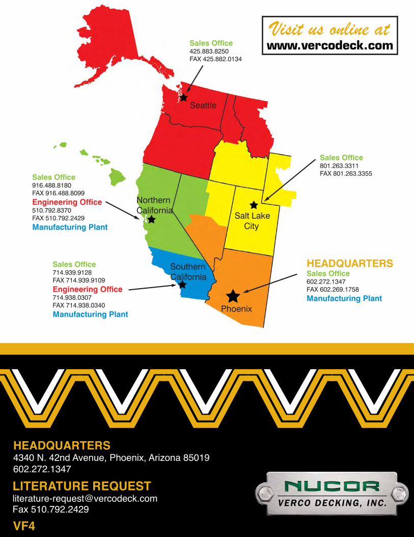
HEADQUARTERS4340 N. 42nd Avenue, Phoenix, Arizona 85019602.272.1347
LITERATURE [email protected] 510.792.2429
Sales Office425.883.8250FAX 425.882.0134
Sales Office801.263.3311FAX 801.263.3355Sales Office
916.488.8180FAX 916.488.8099Engineering Office510.792.8370FAX 510.792.2429Manufacturing Plant
Sales Office714.939.9128FAX 714.939.9109Engineering Office714.938.0307FAX 714.938.0340Manufacturing Plant
HEADQUARTERSSales Office602.272.1347FAX 602.269.1758Manufacturing Plant
Phoenix
NorthernCalifornia
SouthernCalifornia
Salt Lake City
Seattle
Visit us online atwww.vercodeck.com
VF4