thin film transistor lcd module model: awt-480272t43n09 … · microtips technology usa 3504 lake...
TRANSCRIPT

Product Specification Model: AWT-480272T43N09-I Rev. No. Issued Date. Page.
I 2017/01/19 1 / 25
Microtips Technology USA 3504 Lake Lynda Drive, Suite 110, Orlando, FL., USA 32817
Thin Film Transistor LCD MODULE
MODEL: AWT-480272T43N09-I
Customer’s No.:
Acceptance
3504 Lake Lynda Drive, Suite110,
Orlando, FL., USA 32817
Approved and Checked by
Approved by Checked by Made by
MTUSA
NICK
2017/01/19
MTUSA
JOE
2017/01/19
MTUSA
TOM
2017/01/19

Product Specification Model: AWT-480272T43N09-I Rev. No. Issued Date. Page.
I 2017/01/19 2 / 25
Microtips Technology USA 3504 Lake Lynda Drive, Suite 110, Orlando, FL., USA 32817
Record of Revisions Rev Date Sub-Model Description of change
A
B
C
D
E
F
G
H
I
Oct. 26, 2011
Nov. 30, 2011
Dec. 30, 2011
Feb. 22, 2012
Mar. 03, 2012
Mar. 21, 2012
May. 31, 2012
June.04, 2012
Jan.19,2017
Preliminary Product Specification was first issued.
Change Bezel outline and opening size
Change Module outline
Change FPC Tolerance
Change FPC Tolerance
Add 11.Package information
Change FPC Tolerance
Add Current of power supply
1. Modified Page 4 (1.4 Section):
Add information and modified driver IC from
HX8257-A to ST7282.
2. Modified Page 5 (2.1.1 Section):
Power supply voltage from Max. 6.0V to 4.6V.
3. Modified Page 5 (2.1.2 Section):
Forward voltage from 17.8V~18.6V to 16.8V~21V.
Forward current from 30mA~50mA to 38mA~42mA.
4. Modified Page 6 (3.1 Section):
Add color chromaticity WX and WY.
5. Modified Page 12 (5.1 Section):
Add information of note.
6. Modified Page 13 (6.2 Section):
LED current from 30mA~50mA to 38mA~42mA.
LED Voltage from 17.8V~18.6V to 16.8V~21V.
7. Modified Page 14 (6.3 Section):
Modified AC characteristics from Page 14 to Page 17.
8. Modified Page 19(8.0 Section):
Add inspection standard from Page 19 to Page 21.
9. Modified Page 22 (9.0 Section):
1. Modified driver IC from HX8257-A to ST7282.
2. Modified FPC dimension.

Product Specification Model: AWT-480272T43N09-I Rev. No. Issued Date. Page.
I 2017/01/19 3 / 25
Microtips Technology USA 3504 Lake Lynda Drive, Suite 110, Orlando, FL., USA 32817
Table of contents
1. General description
2. Absolute maximum ratings
3. Optical characteristics
4. Block diagram
5 Interface pin connection
6. Electrical characteristics
7. Reliability test items
8. Inspection Standard
9. Outline dimension
10. General precaution
11.Package information

Product Specification Model: AWT-480272T43N09-I Rev. No. Issued Date. Page.
I 2017/01/19 4 / 25
Microtips Technology USA 3504 Lake Lynda Drive, Suite 110, Orlando, FL., USA 32817
1. General description
1.1 Introduction
The model AWT-480272T43N09-I is a color active matrix thin film transistor (TFT) liquid crystal
display (LCD) that uses amorphous silicon TFT as a switching device. This model is composed of a TFT
LCD panel, a driving circuit and a back light system. This TFT LCD has a 4.3 (16:9) inch diagonally
measured active display area with WQVGA (480 horizontal by 272 vertical pixel) resolution.
1.2 Features
4.3 (16:9 diagonal) inch configuration
6 bits + FRC driver with 1channel TTL interface
LED Backlight
Up/Down, Left/Right reversion selection
RoHS Compliance
1.3 Applications
Mobile NB
Digital Photo frame
Multimedia applications and Others AV system
1.4 General information Item Standard Values Units
LCD type 4.3’’TFT --
Dot arrangement 480(RGB)×272 dots
Color filter array RGB vertical stripe --
Display mode TN / Transmission / Normally White -
Gray Scale Inversion Direction 12 O’clock
Eyes Viewing Direction 6 O’clock --
Driver IC ST7282 --
Module size 105.4(W)×67.1(H)×2.8(T) mm
Active area 95.04(W)×53.85(H) mm
Dot pitch 0.198 (W)×0.198 (H) mm
Interface 24-bit Parallel RGB Interface --
Operating temperature -20 ~ +70 °C
Storage temperature -30 ~ +80 °C
Back Light 12 White LEDS --
Weight TBD g
1.5 Mechanical information
item Min. Typ. Max. Unit
Module
Size
Horizontal(H) 105.2 105.4 105.6 mm
Vertical(V) 66.9 67.1 67.3 mm
Depth(D) 2.5 2.8 3.1 mm

Product Specification Model: AWT-480272T43N09-I Rev. No. Issued Date. Page.
I 2017/01/19 5 / 25
Microtips Technology USA 3504 Lake Lynda Drive, Suite 110, Orlando, FL., USA 32817
2. Absolute maximum ratings
2.1 Electrical absolute rating
2.1.1 TFT LCD module
Item Symbol Min. Max. Unit. Note
Power supply voltage VDD -0.3 4.6 V GND=0
Logic Signal Input Level Vi -0.3 VDD+0.3 V
2.1.2 Back-light unit
Item Symbol MIN. TYP. MAX. Unit Note
Forward voltage Vf 16.8 19.2 21.0 V (1)(2)
Forward current If 38 40 42 mA (1)(2) (3)
Power Consumption PBL -- 0.8 -- W
Note:
(1) Permanent damage may occur to the LCD module if beyond this specification. Functional operation
should be restricted to the conditions described under normal operating conditions.
(2) Ta =25±2℃
(3) Test Condition: LED current 40 mA
2.2 Environment absolute rating
Item Symbol Min. Max. Unit Remarks
Operating Temperature Topa -20 +70 ℃
Storage Temperature Tstg -30 +80 ℃
Product Specification Model: AWT-480272T43N09-I Rev. No. Issued Date. Page.
I 2017/01/19 6 / 25
Microtips Technology USA 3504 Lake Lynda Drive, Suite 110, Orlando, FL., USA 32817
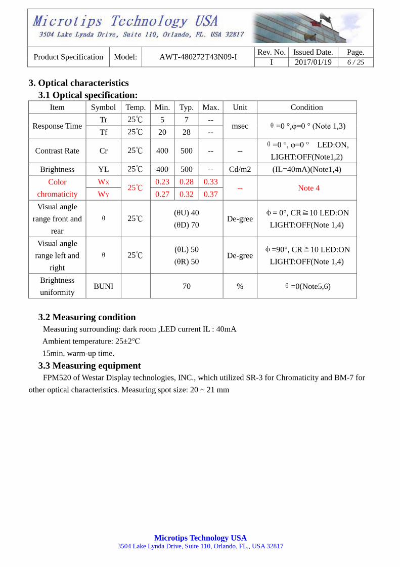
3. Optical characteristics
3.1 Optical specification:
Item Symbol Temp. Min. Typ. Max. Unit Condition
Response Time Tr 25℃ 5 7 --
msec θ=0 °,φ=0 ° (Note 1,3) Tf 25℃ 20 28 --
Contrast Rate Cr 25℃ 400 500 -- -- θ=0 °, φ=0 ° LED:ON,
LIGHT:OFF(Note1,2)
Brightness YL 25℃ 400 500 -- Cd/m2 (IL=40mA)(Note1,4)
Color
chromaticity
WX 25℃
0.23 0.28 0.33 -- Note 4
WY 0.27 0.32 0.37
Visual angle
range front and
rear
θ 25℃ (θU) 40
(θD) 70 De-gree
φ= 0°, CR≧10 LED:ON
LIGHT:OFF(Note 1,4)
Visual angle
range left and
right
θ 25℃ (θL) 50
(θR) 50 De-gree
φ=90°, CR≧10 LED:ON
LIGHT:OFF(Note 1,4)
Brightness
uniformity BUNI
70 % θ=0(Note5,6)
3.2 Measuring condition
Measuring surrounding: dark room ,LED current IL : 40mA
Ambient temperature: 25±2℃
15min. warm-up time.
3.3 Measuring equipment
FPM520 of Westar Display technologies, INC., which utilized SR-3 for Chromaticity and BM-7 for
other optical characteristics. Measuring spot size: 20 ~ 21 mm

Product Specification Model: AWT-480272T43N09-I Rev. No. Issued Date. Page.
I 2017/01/19 7 / 25
Microtips Technology USA 3504 Lake Lynda Drive, Suite 110, Orlando, FL., USA 32817
Note (1) Definition of Viewing Angle :
Note (2) Definition of Contrast Ratio (CR):
Measured at the center point of panel

Product Specification Model: AWT-480272T43N09-I Rev. No. Issued Date. Page.
I 2017/01/19 8 / 25
Microtips Technology USA 3504 Lake Lynda Drive, Suite 110, Orlando, FL., USA 32817
Note (3) Definition of Response Time: Sum of TR and TF
Note (4) Definition of optical measurement setup
500.0MM
FIELD=1.0°
LCD PANEL
Photo detector(BM-7)
Product Specification Model: AWT-480272T43N09-I Rev. No. Issued Date. Page.
I 2017/01/19 9 / 25
Microtips Technology USA 3504 Lake Lynda Drive, Suite 110, Orlando, FL., USA 32817
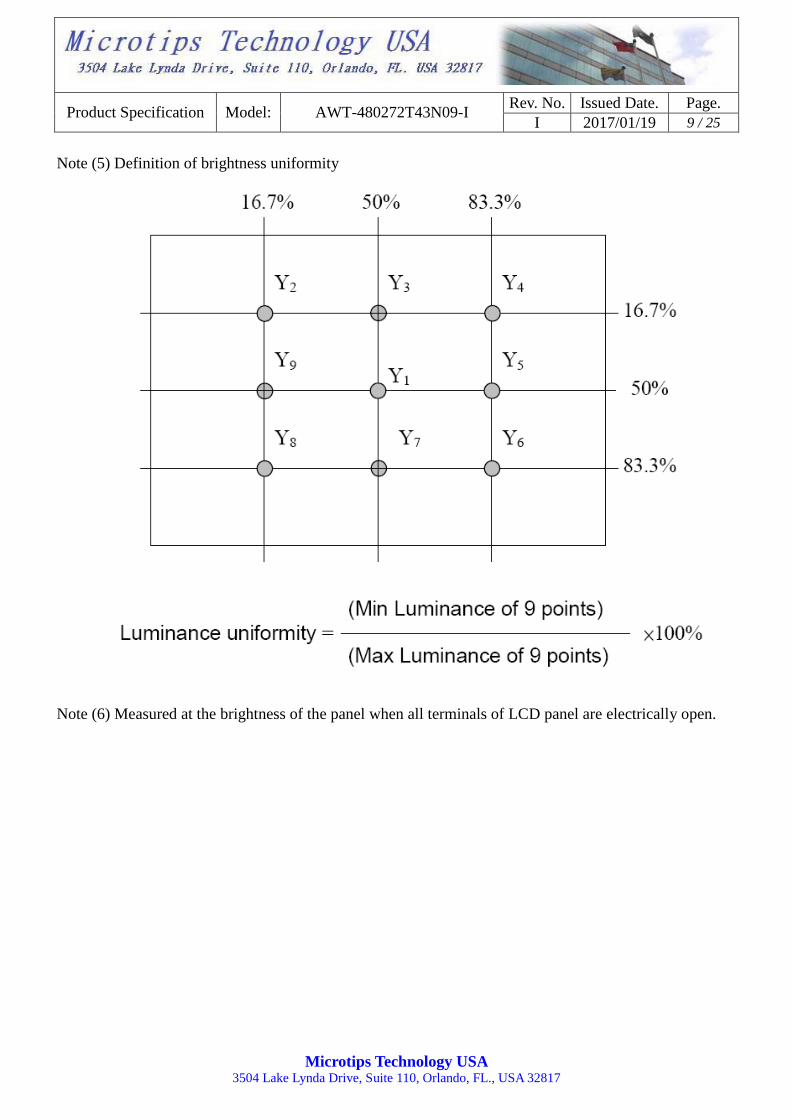
Note (5) Definition of brightness uniformity
Note (6) Measured at the brightness of the panel when all terminals of LCD panel are electrically open.

Product Specification Model: AWT-480272T43N09-I Rev. No. Issued Date. Page.
I 2017/01/19 10 / 25
Microtips Technology USA 3504 Lake Lynda Drive, Suite 110, Orlando, FL., USA 32817
4. Block diagram
4.1 TFT LCD module
4.2 Pixel format
Driver IC
FPC in

Product Specification Model: AWT-480272T43N09-I Rev. No. Issued Date. Page.
I 2017/01/19 11 / 25
Microtips Technology USA 3504 Lake Lynda Drive, Suite 110, Orlando, FL., USA 32817
5. Interface pin connection
5.1 TFT LCD ModuleCN2 (Input signal): FPC Down Connector, (FH28-40S-0.5SH (HIROSE),
40pin, pitch = 0.5mm)
Terminal
No.
Symbol IO Functions
1 LEDK P Power for LED backlight cathode
2 LEDA P Power for LED backlight anode
3 GND P Power Ground
4 VDD P Power Voltage
5 R0 I Data Input(LSB)
6 R1 I Data Input
7 R2 I Data Input
8 R3 I Data Input
9 R4 I Data Input
10 R5 I Data Input
11 R6 I Data Input
12 R7 I Data Input (MSB)
13 G0 I Data Input (LSB)
14 G1 I Data Input
15 G2 I Data Input
16 G3 I Data Input
17 G4 I Data Input
18 G5 I Data Input
19 G6 I Data Input
20 G7 I Data Input(MSB)
21 B0 I Data Input(LSB)
22 B1 I Data Input
23 B2 I Data Input
24 B3 I Data Input
25 B4 I Data Input
26 B5 I Data Input
27 B6 I Data Input
28 B7 I Data Input(MSB)
29 GND P Power Ground
30 DCLK I Dot data clock
31 DISP I Display on/ off

Product Specification Model: AWT-480272T43N09-I Rev. No. Issued Date. Page.
I 2017/01/19 12 / 25
Microtips Technology USA 3504 Lake Lynda Drive, Suite 110, Orlando, FL., USA 32817
32 HSYNC I Horizontal sync Signal
33 VSYNC I Vertical sync signal
34 DE I Data Enable
35 NC -- No Connect
36 GND P Power Ground
37 NC I/O No Connect
38 NC I/O No Connect
39 NC I/O No Connect
40 NC I/O No Connect
NOTE:
VDD(High) GND(Low) Remark
R1 R2 VSYNC polarity control.
”High”, negative polarity “Low:, positive polarity
R3 R4 HSYNC polarity control.
”High”, negative polarity ”Low”, positive polarity
R5 R6 DCLK polarity control.
”High”, negative polarity ”Low”, positive polarity
R7 R8 Horizontal scan direction control..
“High”: Shift from left to right. “Low” : Shift from right to left.
R9 R10
Data R[7:0] & B[7:0] exchanged internally
”High” R[7:0]→B[7:0] B[7:0]→R[7:0]
”Low” R[7:0]→R[7:0] B[7:0]→B[7:0]
R11 R12 ”High”, Parallel 24-bit RGB
”Low”, Serial 8-bit RGB
R13 R14 al scan direction control.
“High”: Shift from up to down. “Low”: Shift from down to up.

Product Specification Model: AWT-480272T43N09-I Rev. No. Issued Date. Page.
I 2017/01/19 13 / 25
Microtips Technology USA 3504 Lake Lynda Drive, Suite 110, Orlando, FL., USA 32817
6. Electrical characteristics
6.1 TFT LCD module
Item Symbol Values
Unit Note Min. Typ. Max.
power Supply voltage VDD 3.0 3.3 3.6 V 2
Input signal voltage ViH 0.7 VDD - VDD V Note (1)
ViL GND - 0.3 VDD V Note (2)
Current of power supply IDD - 22 - mA VDD = 3.3V
Note (1): HSYNC, VSYNC, DE, R/G/B Data
Note (2): GND=0V
6.2 Back-light unit
The backlight system is an edge-lighting type with 12 LED.
The characteristics of the LED are shown in the following tables.
Item Symbol Min. Typ. Max. Unit Note
LED current IL 16.8 19.2 21.0 mA (2)
LED Voltage VL 38 40 42 V
Operating LED life time Hr 20000 - - Hour (1)(2)
Note (1) LED life time (Hr) can be defined as the time in which it continues to operate under the
condition: Ta=25±3℃, typical IL=40mA value indicated in the above table until the brightness becomes
less than 50%.
Note (2) The “LED life time” is defined as the module brightness decrease to 50% original brightness at
Ta=25℃ and IL=40mA. The LED lifetime could be decreased if operating IL is
larger than 40mA. The constant current driving method is suggested.

Product Specification Model: AWT-480272T43N09-I Rev. No. Issued Date. Page.
I 2017/01/19 14 / 25
Microtips Technology USA 3504 Lake Lynda Drive, Suite 110, Orlando, FL., USA 32817
6.3 AC characteristics
6.3.1 Parallel 24-bit RGB Timing Table
6.3.2 Serial 8-bit RGB Timing Table

Product Specification Model: AWT-480272T43N09-I Rev. No. Issued Date. Page.
I 2017/01/19 15 / 25
Microtips Technology USA 3504 Lake Lynda Drive, Suite 110, Orlando, FL., USA 32817
6.3.3 SYNC Mode Timing Diagram
6.3.4 SYNC-DE Mode Timing Diagram

Product Specification Model: AWT-480272T43N09-I Rev. No. Issued Date. Page.
I 2017/01/19 16 / 25
Microtips Technology USA 3504 Lake Lynda Drive, Suite 110, Orlando, FL., USA 32817
6.3.5 DE Mode Timing Diagram
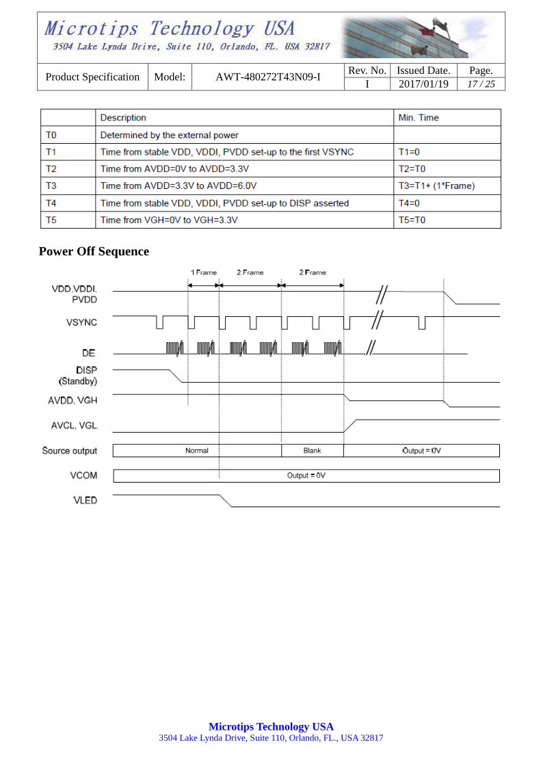
6.3.6 POWER ON/OFF SEQUENCE
Power On Sequence
Product Specification Model: AWT-480272T43N09-I Rev. No. Issued Date. Page.
I 2017/01/19 17 / 25
Microtips Technology USA 3504 Lake Lynda Drive, Suite 110, Orlando, FL., USA 32817
Power Off Sequence
Product Specification Model: AWT-480272T43N09-I Rev. No. Issued Date. Page.
I 2017/01/19 18 / 25
Microtips Technology USA 3504 Lake Lynda Drive, Suite 110, Orlando, FL., USA 32817
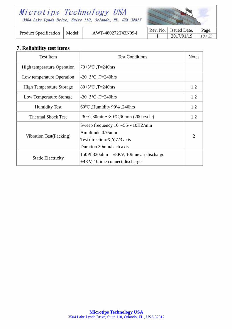
7. Reliability test items
Test Item Test Conditions Notes
High temperature Operation 70±3℃ ,T=240hrs
Low temperature Operation -20±3℃ ,T=240hrs
High Temperature Storage 80±3℃ ,T=240hrs 1,2
Low Temperature Storage -30±3℃ ,T=240hrs 1,2
Humidity Test 60℃ ,Humidity 90% ,240hrs 1,2
Thermal Shock Test -30℃,30min~80℃,30min (200 cycle) 1,2
Vibration Test(Packing)
Sweep frequency 10~55~10HZ/min
Amplitude:0.75mm
Test direction:X,Y,Z/3 axis
Duration 30min/each axis
2
Static Electricity 150Pf 330ohm ±8KV, 10time air discharge
±4KV, 10time connect discharge

Product Specification Model: AWT-480272T43N09-I Rev. No. Issued Date. Page.
I 2017/01/19 19 / 25
Microtips Technology USA 3504 Lake Lynda Drive, Suite 110, Orlando, FL., USA 32817
8. Inspection standard
8.1 Scope
Specifications contain
8.1.1 Display quality evaluation.
8.1.2 Mechanics specification.
8.2 Sampling plan
Unless there is other agreement, the sampling plan for incoming inspection shall follow
MIL-STD-105E.
8.2.1 Lot size: Quantity per shipment as one lot (different model as different lot ).
8.2.2 Sampling type: Normal inspection, single sampling.
8.2.3 Sampling level: Level II.
8.2.4 AQL: Acceptable Quality Level
Major defect: AQL=0.65
Minor defect: AQL=1.0
8.3 Panel inspection condition
8.3.1 Environment:
Room temperature: 25±5°C.
Humidity: 65±5% RH.
Illumination: 300 ~ 700 Lux.
8.3.2 Inspection distance:
35±5 cm.
8.3.3 Inspection angle:
The vision of inspector should be perpendicular to the surface of the Module.
8.3.4 Inspection time:
Perceptibility test time: 20 seconds max.
8.4 Display quality
8.4.1 Function related:
The function defects of line defect, abnormal display, and no display are considered major defects.
Product Specification Model: AWT-480272T43N09-I Rev. No. Issued Date. Page.
I 2017/01/19 20 / 25
Microtips Technology USA 3504 Lake Lynda Drive, Suite 110, Orlando, FL., USA 32817
R
G
B
R
G
B
R
G
B
Dot defect
R
G
B
R
G
B
R
G
B
Adjacent dot defect
R
G
B
R
G
B
R
G
B
cluster
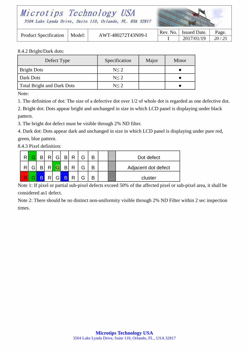
8.4.2 Bright/Dark dots:
Defect Type Specification Major Minor
Bright Dots N≤ 2 ●
Dark Dots N≤ 2 ●
Total Bright and Dark Dots N≤ 2 ●
Note:
1. The definition of dot: The size of a defective dot over 1/2 of whole dot is regarded as one defective dot.
2. Bright dot: Dots appear bright and unchanged in size in which LCD panel is displaying under black
pattern.
3. The bright dot defect must be visible through 2% ND filter.
4. Dark dot: Dots appear dark and unchanged in size in which LCD panel is displaying under pure red,
green, blue pattern.
8.4.3 Pixel definition:
Note 1: If pixel or partial sub-pixel defects exceed 50% of the affected pixel or sub-pixel area, it shall be
considered as1 defect.
Note 2: There should be no distinct non-uniformity visible through 2% ND Filter within 2 sec inspection
times.

Product Specification Model: AWT-480272T43N09-I Rev. No. Issued Date. Page.
I 2017/01/19 21 / 25
Microtips Technology USA 3504 Lake Lynda Drive, Suite 110, Orlando, FL., USA 32817
8.4.4 Visual inspection specifications:
Defect Type Specification Size Count(N) Major Minor
Dot Shape
(Particle、Scratch and Bubbles in
display area)
D ≤ 0.20 mm Ignored
●
0.20mm < D ≤ 0.30mm N ≤ 2
D > 0.30mm N=0
Line Shape (Particles、
Scratch、Lint and Bubbles in
display area)
W ≤ 0.03 mm Ignored
●
0.03mm< W ≤ 0.04mm
and L ≤ 4mm N ≤ 1
0.04mm< W ≤ 0.05mm
and L ≤ 4mm N ≤ 1
W > 0.05mm or L > 4
mm N=0
Bubble in cell (active area) It should be found by eyes ●
Bezel
Scratch No harm
●
Dirt ●
Wrap No harm ●
Sunken No harm ●
Label
No label
No
●
Inverted label ●
Broken ●
Dirt Word can be read. ●
Not clear No
●
Word out of shape ●
Mistake No ●
Position Be attached on right position ●
Screw Not enough No ●
Limp No ●
Connector Connection status No bend on pins and damage ●
FPC/FFC Broken No ●
Note: Extraneous substance and scratch not affecting the display of image, for instance, extraneous
substance under polarizer film but outside the display area, or scratch on metal bezel and backlight
module or polarizer film outside the display area, shall not be considered as defective or
non-conforming.
Product Specification Model: AWT-480272T43N09-I Rev. No. Issued Date. Page.
I 2017/01/19 22 / 25
Microtips Technology USA 3504 Lake Lynda Drive, Suite 110, Orlando, FL., USA 32817
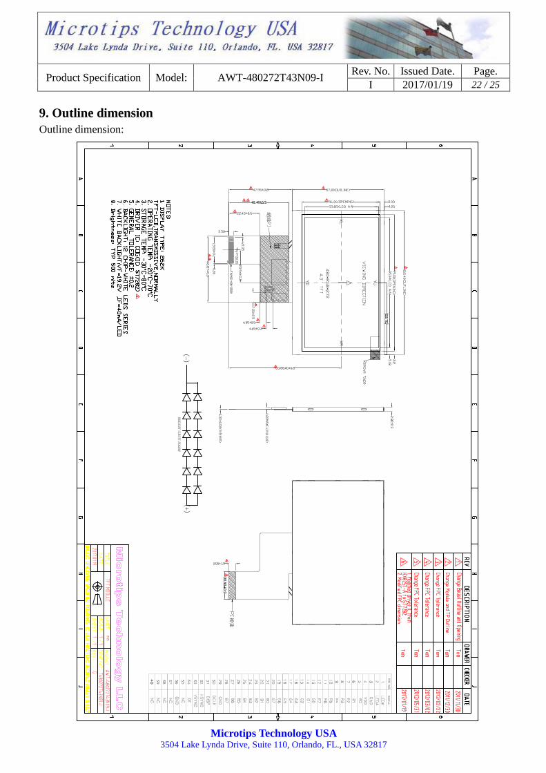
9. Outline dimension
Outline dimension:

Product Specification Model: AWT-480272T43N09-I Rev. No. Issued Date. Page.
I 2017/01/19 23 / 25
Microtips Technology USA 3504 Lake Lynda Drive, Suite 110, Orlando, FL., USA 32817
10. General precaution
10.1 Use restriction
This product is not authorized for use in life supporting systems, aircraft navigation control systems,
military systems and any other application where performance failure could be life threatening or
otherwise catastrophic.
10.2 Disassembling or modification
Do not disassemble or modify the module. It may damage sensitive parts inside LCD module, and
may cause scratches or dust on the display. ACROWISE does not warrant the module, if customers
disassemble or modify the module.
10.3 Breakage of LCD panel
10.3.1.If LCD panel is broken and liquid crystal spills out, do not ingest or inhale liquid crystal, and do
not contact liquid crystal with skin.
10.3.2. If liquid crystal contacts mouth or eyes, rinse out with water immediately.
10.3.3. If liquid crystal contacts skin or cloths, wash it off immediately with alcohol and rinse thoroughly
with water.
10.3.4. Handle carefully with chips of glass that may cause injury, when the glass is broken.
10.4 Electric shock
10.4.1. Disconnect power supply before handling LCD module.
10.4.2. Do not pull or fold the LED cable.
10.4.3. Do not touch the parts inside LCD modules and the fluorescent LED’s connector or cables in
order to prevent electric shock.
10.5 Absolute maximum ratings and power protection circuit
10.5.1. Do not exceed the absolute maximum rating values, such as the supply voltage variation, input
voltage variation, variation in parts’ parameters, environmental temperature, etc., otherwise LCD module
may be damaged.
10.5.2. Please do not leave LCD module in the environment of high humidity and high temperature for a
long time.
10.5.3. It’s recommended to employ protection circuit for power supply.
10.6 Operation
10.6.1 Do not touch, push or rub the polarizer with anything harder than HB pencil lead.
10.6.2 Use fingerstalls of soft gloves in order to keep clean display quality, when persons handle the LCD

Product Specification Model: AWT-480272T43N09-I Rev. No. Issued Date. Page.
I 2017/01/19 24 / 25
Microtips Technology USA 3504 Lake Lynda Drive, Suite 110, Orlando, FL., USA 32817
module for incoming inspection or assembly.
10.6.3 When the surface is dusty, please wipe gently with absorbent cotton or other soft material.
10.6.4 Wipe off saliva or water drops as soon as possible. If saliva or water drops contact with polarizer
for a long time, they may causes deformation or color fading.
10.6.5 When cleaning the adhesives, please use absorbent cotton wetted with a little petroleum benzine or
other adequate solvent.
10.7 Mechanism
Please mount LCD module by using mouting holes arranged in four corners tightly.
10.8 Static electricity
10.8.1 Protection film must remove very slowly from the surface of LCD module to prevent from
electrostatic occurrence.
10.8.2. Because LCD module use CMOS-IC on circuit board and TFT-LCD panel, it is very weak to
electrostatic discharge. Please be careful with electrostatic discharge. Persons who handle the module
should be grounded through adequate methods.
10.9 Strong light exposure
The module shall not be exposed under strong light such as direct sunlight. Otherwise, display
characteristics may be changed.
10.10 Disposal
When disposing LCD module, obey the local environmental regulations.
Product Specification Model: AWT-480272T43N09-I Rev. No. Issued Date. Page.
I 2017/01/19 25 / 25
Microtips Technology USA 3504 Lake Lynda Drive, Suite 110, Orlando, FL., USA 32817
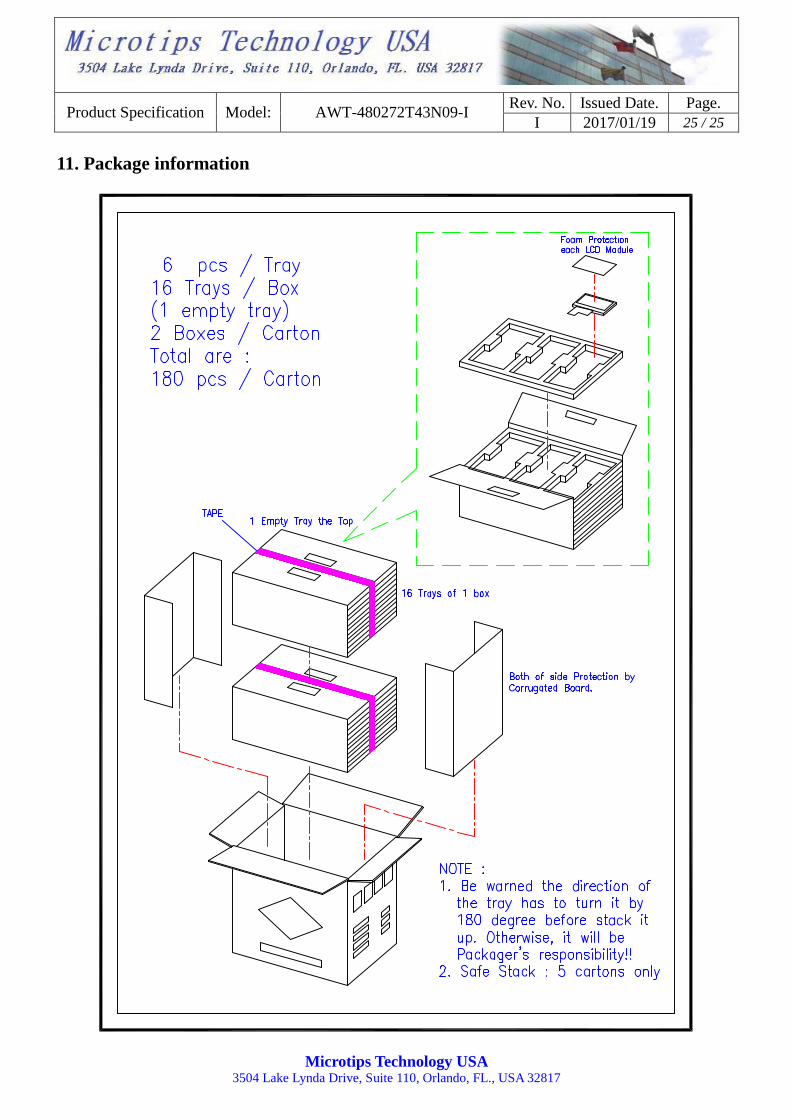
11. Package information